APWM AL1663/AL1663R NC FB APWM UNIVERSAL … AL1663/AL1663R is a high performance single stage...
15
AL1663/AL1663R Document number: DS38466 Rev. 2 - 2 1 of 15 www.diodes.com March 2017 © Diodes Incorporated AL1663/AL1663R UNIVERSAL FLYBACK AND BUCK-BOOST SINGLE STAGE DIMMABLE LED CONTROLLER Description The AL1663/AL1663R is a high performance single stage Flyback and Buck-boost controller, targeting dimmable LED lighting application. It is a primary side regulation (PSR) controller which can provide accurate constant current (CC) regulation without opto- coupler and secondary control circuitry. It is operating at BCM mode and switching at the valley which results in good EMI and efficiency. With working in constant on time, the system achieves high PF and low total harmonic distortion (THD) under universal input voltage. The AL1663/AL1663R can support multiple dimming modes. When a 0.3V to 2.4V DC signal is applied on APWM pin, the device will operate in analog dimming mode. When a digital signal is applied on APWM pin, the device works at PWM dimming mode. And for AL1663 When a digital signal is applied on PWMD pin and the APWM pin is connected with a hundreds of nF capacitor, the device will work in PWM-to-DC dimming mode. The AL1663/AL1663R features low start-up current and low operation current. It integrates multiple protections including over voltage, short circuit, over current and over temperature protection. The AL1663/AL1663R is available in SO-8 package. Features Primary Side Regulation without Opto-coupler Valley Switching for Low Switching Loss Low Start-up Current High PF and Low THD High Efficiency Tight LED Current Variation Range Tight Output Open Voltage Variation Range Support both PWM Dimming and Analog Dimming Internal Protections Under Voltage Lock Out (UVLO) Output Over Voltage Protection (OVP) Output Short Protection (OSP) Over Current Protection (OCP) Thermal Fold-back Protection (TFP) Over Temperature Protection (OTP) Low System Cost Package: SO-8 Totally Lead-Free & Fully RoHS Compliant (Notes 1 & 2) Halogen and Antimony Free. “Green” Device (Note 3) Pin Assignments (Top View) AL1663 AL1663R SO-8 SO-8 Applications General LED Lighting Driver with Dimming Function General Purpose Constant Current Source LED Backlighting Driver Smart LED Lighting Notes: 1. No purposely added lead. Fully EU Directive 2002/95/EC (RoHS) & 2011/65/EU (RoHS 2) compliant. 2. See http://www.diodes.com/quality/lead_free.html for more information about Diodes Incorporated’s definitions of Halogen- and Antimony-free, "Green" and Lead-free. 3. Halogen- and Antimony-free "Green” products are defined as those which contain <900ppm bromine, <900ppm chlorine (<1500ppm total Br + Cl) and <1000ppm antimony compounds. 1 2 3 4 8 6 5 7 APWM PWMD COMP CS GND FB OUT VCC 1 2 3 4 8 6 5 7 NC FB CS GND OUT APWM VCC COMP
-
Upload
trinhthien -
Category
Documents
-
view
216 -
download
2
Transcript of APWM AL1663/AL1663R NC FB APWM UNIVERSAL … AL1663/AL1663R is a high performance single stage...

AL1663/AL1663R Document number: DS38466 Rev. 2 - 2
1 of 15 www.diodes.com
March 2017 © Diodes Incorporated
AL1663/AL1663R
UNIVERSAL FLYBACK AND BUCK-BOOST
SINGLE STAGE DIMMABLE LED CONTROLLER
Description
The AL1663/AL1663R is a high performance single stage Flyback
and Buck-boost controller, targeting dimmable LED lighting
application. It is a primary side regulation (PSR) controller which can
provide accurate constant current (CC) regulation without opto-
coupler and secondary control circuitry. It is operating at BCM mode
and switching at the valley which results in good EMI and efficiency.
With working in constant on time, the system achieves high PF and
low total harmonic distortion (THD) under universal input voltage.
The AL1663/AL1663R can support multiple dimming modes. When a
0.3V to 2.4V DC signal is applied on APWM pin, the device will
operate in analog dimming mode. When a digital signal is applied on
APWM pin, the device works at PWM dimming mode. And for AL1663
When a digital signal is applied on PWMD pin and the APWM pin is
connected with a hundreds of nF capacitor, the device will work in
PWM-to-DC dimming mode.
The AL1663/AL1663R features low start-up current and low operation
current. It integrates multiple protections including over voltage, short
circuit, over current and over temperature protection.
The AL1663/AL1663R is available in SO-8 package.
Features
Primary Side Regulation without Opto-coupler
Valley Switching for Low Switching Loss
Low Start-up Current
High PF and Low THD
High Efficiency
Tight LED Current Variation Range
Tight Output Open Voltage Variation Range
Support both PWM Dimming and Analog Dimming
Internal Protections
Under Voltage Lock Out (UVLO)
Output Over Voltage Protection (OVP)
Output Short Protection (OSP)
Over Current Protection (OCP)
Thermal Fold-back Protection (TFP)
Over Temperature Protection (OTP)
Low System Cost
Package: SO-8
Totally Lead-Free & Fully RoHS Compliant (Notes 1 & 2)
Halogen and Antimony Free. “Green” Device (Note 3)
Pin Assignments
(Top View)
AL1663 AL1663R
SO-8 SO-8
Applications
General LED Lighting Driver with Dimming Function
General Purpose Constant Current Source
LED Backlighting Driver
Smart LED Lighting
Notes: 1. No purposely added lead. Fully EU Directive 2002/95/EC (RoHS) & 2011/65/EU (RoHS 2) compliant.
2. See http://www.diodes.com/quality/lead_free.html for more information about Diodes Incorporated’s definitions of Halogen- and Antimony-free, "Green"
and Lead-free.
3. Halogen- and Antimony-free "Green” products are defined as those which contain <900ppm bromine, <900ppm chlorine (<1500ppm total Br + Cl) and
<1000ppm antimony compounds.
1
2
3
4
8
6
5
7
APWM
PWMD
COMP
CS GND
FB
OUT
VCC
1
2
3
4
8
6
5
7
NC
FB
CS
GND OUT
APWM
VCC
COMP

AL1663/AL1663R Document number: DS38466 Rev. 2 - 2
2 of 15 www.diodes.com
March 2017 © Diodes Incorporated
AL1663/AL1663R
Typical Applications Circuit
T1
OUT+
VCC OUT
CS GND
U1
R5
R6
R4 D1
C6 RTH
AC Input
F 1
VR 1
DB1
C2
L1
C1
RCS
R10
FB
COMP
D2
C5
R14C7
D3
Q1
Ccomp
Aux
PWMD
R9
D4
AL1663
APWM
Rcomp
Cvcc
AL1663 Flyback Application Circuit
T1OUT
VCC OUT
CS GND
R5
R6
R4 D1
C6RTH
AC Input
F 1
VR 1
DB1
C2
L1
C1
RCS
FB
COMP
Q1
Ccomp
Aux
PWMD
R9
D4
AL1663
Rcomp
Cvcc
D3
+
R11
APWM
AL1663 Buck-Boost Application Circuit
T1
OUT+
VCC OUT
CS GND
U1
R5
R6
R4 D1
C6 RTH
AC Input
F 1
VR 1
DB1
C2
L1
C1
RCS
R10
FB
COMP
D2
C5
R14C7
D3
Q1
Ccomp
Aux
NC
R9
D4APWM
Rcomp
Cvcc
AL1663R
AL1663R Flyback Application Circuit

AL1663/AL1663R Document number: DS38466 Rev. 2 - 2
3 of 15 www.diodes.com
March 2017 © Diodes Incorporated
AL1663/AL1663R
Pin Descriptions
Pin Number Pin Name Function
AL1663 AL1663R
1 8 APWM Analog dimming input pin or PWM signal input pin in PWM dimming mode
2 — PWMD PWMD signal input pin in PWM-to-DC dimming mode
— 1 NC Not Connected
3 7 COMP Loop compensation pin
4 3 CS Current sense pin, connect this pin to the source of the primary switch
5 4 GND Ground
6 5 OUT Gate driver output
7 6 VCC Supply voltage of gate driver and control circuits of the IC
8 2 FB The feedback voltage sensing from the auxiliary winding
Functional Block Diagram
Valley
Detector
Logical
Control
UVLO
&Bias
Driver
-
+
COMP
FB
OVP
CS
VCC
OUT
Gm
OTP
GND
DIM
Control
VREFPWMD
APWM
Buffer
-
+
1.2V
OCP
TFP
VREF
VREF
Temperature
Detector
TFP
OTP
1(8)
2
3(7)
4(3)
5(4)
8(2)
7(6)
6(5)
A(B) A for AL1663 B for AL1663R

AL1663/AL1663R Document number: DS38466 Rev. 2 - 2
4 of 15 www.diodes.com
March 2017 © Diodes Incorporated
AL1663/AL1663R
Absolute Maximum Ratings (@TA = +25°C, unless otherwise specified.) (Note 4)
Symbol Parameter Rating Unit
VCC Power Supply Voltage -0.3 to 30 V
VCS Voltage at CS to GND -0.3 to 7 V
VFB FB Input -0.3 to 7 V
VCOMP Loop Compensation Pin -0.3 to 7 V
VOUT Driver Output Voltage -0.3 to 20 V
VPWMD Voltage at PWMD to GND -0.3 to 7 V
VAPWM Voltage at APWM to GND -0.3 to 7 V
TJ Operating Junction Temperature -40 to +150 ºC
TSTG Storage Temperature -65 to +150 ºC
TLEAD Lead Temperature (Soldering, 10 sec) +300 ºC
PD Power Dissipation at TA = +50ºC 0.65 W
θJA Thermal Resistance (Junction to Ambient) 150 ºC/W
θJC Thermal Resistance (Junction to Case) 23 °C/W
—
ESD (Human Body Model) 2000 V
CDM (Charged-Device Model) 1000 V
Note: 4. Stresses greater than those listed under “Absolute Maximum Ratings” may cause permanent damage to the device. These are stress ratings only, and functional operation of the device at these or any other conditions beyond those indicated under “Recommended Operating Conditions” is not implied. Exposure to “Absolute Maximum Ratings” for extended periods may affect device reliability. All voltages unless otherwise stated and measured with respect to GND.
Recommended Operating Conditions (@TA = +25°C, unless otherwise specified.)
Symbol Parameter Min Max Unit
TA Ambient Temperature (Note 5) -40 +105 °C
Note: 5. The device may operate normally at +125°C ambient temperature under the condition not triggers temperature protection.

AL1663/AL1663R Document number: DS38466 Rev. 2 - 2
5 of 15 www.diodes.com
March 2017 © Diodes Incorporated
AL1663/AL1663R
Electrical Characteristics (@TA = +25°C, unless otherwise specified.)
Symbol Parameter Condition Min Typ Max Unit
UVLO Section
VCC_TH Startup Threshold Voltage — 17 18.5 20 V
VOPR_MIN Minimal Operating Voltage After Turn On 7 7.8 8.5 V
VCC_OVP VCC OVP Voltage — 25 27 29.9 V
Standby Current Section
IST Startup Current VCC = VCC_TH -0.5V, before start up
— 0.8 — µA
ICC Operating Current FB, CS connect to GND, CGATE = 100pF
— 1 — mA
ICC_OVP Shunt Current in OVP Mode VCC > VCC_OVP — 5 — mA
Drive Output Section
tR Output Voltage Rise Time (Note 6) CL = 1nF — 90 — ns
tF Output Voltage Fall Time (Note 6) CL = 1nF — 30 — ns
VOUT_CLAMP Output Clamp Voltage VCC = 20V 13 14 15 V
tON_MIN Minimum On Time (Note 6) — — 400 — ns
tON_MAX Maximum On Time — — 22 — µs
tOFF_MAX Maximum Off Time — — 35 — µs
tOFF_MIN Minimum Off Time — — 2 — µs
fMAX Maximum Frequency — — 150 — kHz
Internal CS reference
VREF Internal Reference Voltage — 0.291 0.3 0.309 V
VCS_OCP Primary Current Clamp Voltage — — 1.2 — V
Error Amplifier
Gm Trans-Conductance — — 16.7 — µA/V
ISOURCE Amplifier Source Current — — 10 — µA
Feedback Input Section
VFB_CV FB CV Threshold — 1.4 1.5 1.6 V
APWM Section
VAPWM_L PWM Signal Low Threshold Voltage — — — 0.3 V
VAPWM_H PWM Signal High Threshold Voltage — 2.4 — — V
— Linear Dimming Range on APWM — 0.3 — 2.4 V
PWMD Section
VPWM_L PWM Signal Low Threshold Voltage — — — 0.4 V
VPWM_H PWM Signal High Threshold Voltage — 2 — — V
Thermal Fold-back Section
TREG Overheating Temperature Regulation
(Note 6) — — +145 —
oC
Over Temperature Protection Section
— Shutdown Temperature (Notes 6, 7) — — +165 — oC
Notes: 6. These parameters, although guaranteed by design, are not 100% tested in production.
7. The device will latch when OTP happens and the device won’t operate constantly at this temperature.

AL1663/AL1663R Document number: DS38466 Rev. 2 - 2
6 of 15 www.diodes.com
March 2017 © Diodes Incorporated
AL1663/AL1663R
Performance Characteristics (Note 8)
Startup Threshold Voltage vs. Ambient Temperature Minimum Operating Voltage vs. Ambient Temperature
Operating Current vs. Ambient Temperature FB CV Threshold vs. Ambient Temperature
Internal Reference Voltage vs. Ambient Temperature FB CV Threshold vs. VCC Voltage
-40 -20 0 20 40 60 80 100 12018.0
18.5
19.0
19.5
20.0
VC
C_
TH
(V)
Ambient Temperature (oC)
-40 -20 0 20 40 60 80 100 1200.9
1.0
1.1
1.2
1.3
1.4
I CC
(mA
)
Ambient Temperature (oC)
-40 -20 0 20 40 60 80 100 1201.2
1.3
1.4
1.5
1.6
1.7
VF
B_
CV
(V)
Ambient Temperature (oC)
-40 -20 0 20 40 60 80 100 1207.0
7.2
7.4
7.6
7.8
8.0
VO
PR
_M
IN (
V)
Ambient Temperature (oC)
9 12 15 18 21 24 271.2
1.3
1.4
1.5
1.6
1.7
1.8
VF
B_
CV (
V)
VCC
Voltage(V)
-40 -20 0 20 40 60 80 100 120288
292
296
300
304
308
312
VR
EF (
mV
)
Ambient Temperature (oC)

AL1663/AL1663R Document number: DS38466 Rev. 2 - 2
7 of 15 www.diodes.com
March 2017 © Diodes Incorporated
AL1663/AL1663R
Performance Characteristics (Cont.)
Internal Reference Voltage vs. VCC Voltage
Note: 8. These electrical characteristics are tested under DC condition. The ambient temperature is equal to the junction temperature of the device.
Application Information
The AL1663/AL1663R is a constant current high PF Flyback and Buck-boost controller with primary side regulation (PSR), targeting LED lighting
applications. The device eliminates the opto-couplers or the secondary feedback circuits, which will help to cost down the whole system. High
power factor is achieved by constant on time operation. In order to reduce the switching losses and improve EMI performance, quasi-resonant
switching mode is applied. The AL1663/AL1663R integrates multiple protections including UVLO protection, VCC over voltage protection, output
open voltage protection, over current protection, thermal fold-back protection and over temperature protection. The AL1663/AL1663R can support
multiple dimming modes including analog dimming mode, PWM-to-DC dimming mode and PWM dimming.
T1
OUT+
VCC OUT
CS GND
U1
R5
R6
R4 D1
C6 RTH
AC Input
F 1
VR 1
DB1
C2
L1
C1
RCS
R10
FB
COMP
D2
C5
R14C7
D3
Q1
Ccomp
Aux
PWMD
R9
D4
AL1663
APWM
Rcomp
Cvcc
Figure 1. AL1663 Typical Flyback Application Schematic
T1
OUT+
VCC OUT
CS GND
U1
R5
R6
R4 D1
C6 RTH
AC Input
F 1
VR 1
DB1
C2
L1
C1
RCS
R10
FB
COMP
D2
C5
R14C7
D3
Q1
Ccomp
Aux
NC
R9
D4
AL1663R
APWM
Rcomp
Cvcc
Figure 2. AL1663R Flyback Application Circuit
9 12 15 18 21 24 27290
295
300
305
310
VR
EF (
mV
)
VCC
Voltage(V)
AL1663/AL1663R Document number: DS38466 Rev. 2 - 2
8 of 15 www.diodes.com
March 2017 © Diodes Incorporated
AL1663/AL1663R
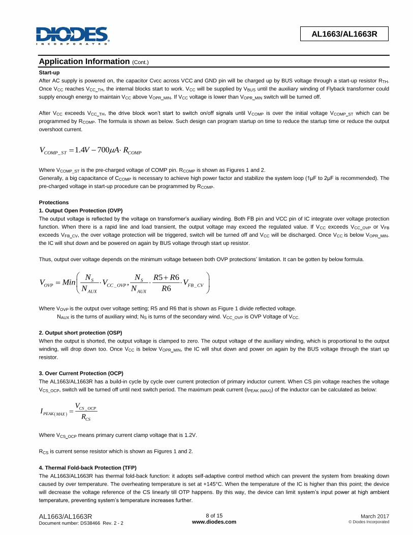
Application Information (Cont.)
Start-up
After AC supply is powered on, the capacitor Cvcc across VCC and GND pin will be charged up by BUS voltage through a start-up resistor RTH.
Once VCC reaches VCC_TH, the internal blocks start to work. VCC will be supplied by VBUS until the auxiliary winding of Flyback transformer could
supply enough energy to maintain VCC above VOPR_MIN. If VCC voltage is lower than VOPR_MIN switch will be turned off.
After VCC exceeds VCC_TH, the drive block won’t start to switch on/off signals until VCOMP is over the initial voltage VCOMP_ST which can be
programmed by RCOMP. The formula is shown as below. Such design can program startup on time to reduce the startup time or reduce the output
overshoot current.
COMPSTCOMP RAVV 7004.1_
Where VCOMP_ST is the pre-charged voltage of COMP pin. RCOMP is shown as Figures 1 and 2.
Generally, a big capacitance of CCOMP is necessary to achieve high power factor and stabilize the system loop (1μF to 2μF is recommended). The
pre-charged voltage in start-up procedure can be programmed by RCOMP.
Protections
1. Output Open Protection (OVP)
The output voltage is reflected by the voltage on transformer’s auxiliary winding. Both FB pin and VCC pin of IC integrate over voltage protection
function. When there is a rapid line and load transient, the output voltage may exceed the regulated value. If VCC exceeds VCC_OVP or VFB
exceeds VFB_CV, the over voltage protection will be triggered, switch will be turned off and VCC will be discharged. Once VCC is below VOPR_MIN.
the IC will shut down and be powered on again by BUS voltage through start up resistor.
Thus, output over voltage depends on the minimum voltage between both OVP protections’ limitation. It can be gotten by below formula.
_ _
5 6,
6
S SOVP CC OVP FB CV
AUX AUX
N N R RV Min V V
N N R
Where VOVP is the output over voltage setting; R5 and R6 that is shown as Figure 1 divide reflected voltage.
NAUX is the turns of auxiliary wind; NS is turns of the secondary wind. VCC_OVP is OVP Voltage of VCC.
2. Output short protection (OSP)
When the output is shorted, the output voltage is clamped to zero. The output voltage of the auxiliary winding, which is proportional to the output
winding, will drop down too. Once VCC is below VOPR_MIN, the IC will shut down and power on again by the BUS voltage through the start up
resistor.
3. Over Current Protection (OCP)
The AL1663/AL1663R has a build-in cycle by cycle over current protection of primary inductor current. When CS pin voltage reaches the voltage
VCS_OCP, switch will be turned off until next switch period. The maximum peak current (IPEAK (MAX)) of the inductor can be calculated as below:
_CS OCP
PEAK MAX
CS
VI
R
Where VCS_OCP means primary current clamp voltage that is 1.2V.
RCS is current sense resistor which is shown as Figures 1 and 2.
4. Thermal Fold-back Protection (TFP)
The AL1663/AL1663R has thermal fold-back function: it adopts self-adaptive control method which can prevent the system from breaking down
caused by over temperature. The overheating temperature is set at +145°C. When the temperature of the IC is higher than this point; the device
will decrease the voltage reference of the CS linearly till OTP happens. By this way, the device can limit system’s input power at high ambient
temperature, preventing system’s temperature increases further.

AL1663/AL1663R Document number: DS38466 Rev. 2 - 2
9 of 15 www.diodes.com
March 2017 © Diodes Incorporated
AL1663/AL1663R
Application Information (Cont.)
5. Over Temperature Protection (OTP)
The AL1663/AL1663R has build-in over temperature protection (OTP) function. When the temperature goes up to +165°C, the over temperature
protection will be triggered, which leads to a latch mode protection. When OTP happens, the system need to be powered off and on again to
restart.
Output Constant-current Control
According to the definition of mean output current, the mean output current can be obtained as below.
dtt
tII
SW
ONSSPMEANO
0
_2
11
Where IO_MEAN is the mean output current; ISP is secondary peak current of transformer;
tONS is discharge time of secondary side of transformer; tSW is the switch period.
According to the principle of AL1663/AL1663R close loop control, the voltage of RCS will be sampled when switch is turned off and the value will
be held until discharge time tONS is over. It can be described by following formula:
dtt
tRIV
SW
ONSCSPREF
0
1
Where IP is primary peak current of transformer; RCS is current sense resistor which is shown as Figures 1 and 2.
tONS is discharge time of secondary side of transformer; tSW is the switch period. VREF is internal reference voltage that is equal to 0.3V.
The peak current at secondary side has following relationship with primary side peak current, if the effect of the leakage inductor is neglected.
SP PS PI N I
Where NPS is the turns ratio of Flyback transformer (NPS=1 for Buck-boost); IP is the primary peak current of the transformer.
According to these above formulas, the mean output current can be induced finally by below expressions.
_2
PS REFO MEAN
CS
N VI
R
Where IO_MEAN is the mean output current; RCS is current sense resistor which is shown as Figures 1 and 2;
VREF is internal reference voltage that is equal to 0.3V; NPS is the turns ratio of Flyback transformer (NPS=1 for Buck-boost);
Therefore, the constant output current control can be realized with appropriate parameter design.
PF and THD compensation circuit
For normal application, AL1663/AL1663R can provide high PF and low THD. But there is a phase difference between input current and input
voltage especially at high input voltage, thus PF and THD may not be the best situation. The below circuit can optimize this situation by reducing
the phase difference. VBUS is connected to the voltage point after rectifier. In normal application resistor RN1 is usually a several hundred kΩ
resistor, RN2 is a hundred Ω resistor, CN1 is a several µF capacitor. PF and THD can be improved by debugging these components.
COMPCcomp
Rcomp
VBUS
CN1
RN1
RN2
Figure 3. PF and THD Optimization Circuit

AL1663/AL1663R Document number: DS38466 Rev. 2 - 2
10 of 15 www.diodes.com
March 2017 © Diodes Incorporated
AL1663/AL1663R
0 20 40 60 80 1000
20
40
60
80
100
Ou
tpu
t C
urr
en
t P
erc
en
tag
e (
%)
PWM Duty (%)
Application Information (Cont.)
Dimming Mode
The AL1663 can support three dimming modes: analog dimming, PWM-to-DC dimming and PWM dimming.
The AL1663R can support two dimming modes: analog dimming and PWM dimming.
1. Analog Dimming Mode
In analog dimming mode, the dimming signal is added to APWM pin directly to realize dimming function. The setting circuit is shown as Figure 4. A
capacitance of hundreds nF is recommended for CAPWM. When VAPWM is higher than 2.4V, the driver will output 100% of rated current; when the
voltage VAPWM is in the range from 0.3 to 2.4V, the output current will change linearly with the voltage VAPWM. When VAPWM is lower than 0.3V,
switch will be turned off and the output current drops to zero. The dimming curve is shown as Figure 5 and the dimming range is from 12% to
100%.
Figure 4. Analog Dimming Setting Circuit Figure 5. Analog Dimming Curve
2. PWM-to-DC Dimming Mode
In PWM-to-DC dimming mode, PWM dimming signal is added to PWMD pin. The setting circuit is shown as below Figure 6. A capacitance of
hundreds nF is recommended for CAPWM. The duty cycle of the dimming signal DDIM is reflected by the voltage on APWM pin VAPWM.
2.4APWM DIMV D V
Where DDIM is duty of PWM signal; VAPWM is the voltage of APWM pin.
Thus the output current will change with the duty cycle of dimming signal DDIM. For example, the dimming curve is shown as Figure 7. The
dimming range is 12% to 100%.
Figure 6. PWM to DC Dimming Setting Circuit Figure 7. PWM to DC Dimming Curve (PWM Frequency is 500Hz)
3. PWM Dimming Mode
In PWM dimming mode, dimming signal will be added to APWM pin .The setting circuit is shown as Figure 8. The output current is chopped by the
dimming signal directly. The logic high level of the dimming signal needs to be higher 2.4V while the logic low level is lower than 0.3V. Switch is
turned off at logic low level. The dimming curve is shown as Figure 9. The dimming range can be 100 to 1% with 1kHz frequency of PWM signal.
Figure 8. PWM Dimming Setting Circuit Figure 9. PWM Dimming Curve (PWM Frequency is 1 KHz)
0.0 0.5 1.0 1.5 2.0 2.5 3.00
20
40
60
80
100
Ou
tpu
t C
urr
en
t P
erc
en
t (%
)
VAPMW
(V)
0 20 40 60 80 1000
20
40
60
80
100
Ou
tpu
t C
urr
en
t P
erc
en
t (%
)
PWM Duty (%)
APWM
AL1663/AL1663R
0.3-2.4V
Dimming Signal
CA
PW
MAPWM
PWMD
AL1663
CA
PW
M
R
APWM
AL1663/AL1663R
PWM Dimming Signal

AL1663/AL1663R Document number: DS38466 Rev. 2 - 2
11 of 15 www.diodes.com
March 2017 © Diodes Incorporated
AL1663/AL1663R
Application Information (Cont.)
Operation Parameters Design
Setting the Current Sense Resistor RCS
The current sense resistance can be calculated as following:
_2
PS REFCS
O MEAN
N VR
I
Where IO_MEAN is the mean output current; RCS is current sense resistor which is shown as Figures 1 and 2;
VREF is internal reference voltage that is equal to 0.3V; NPS is the turns ratio of Flyback transformer (NPS=1 for Buck-boost).
Setting Transformer Selection (T1)
NPS is limited by the electrical stress of the switch MOSFET, can be calculated by below formula.
_( ) _
_
90% 2MOS BR DS IN MAX S
PS
O D F
V V VN
V V
Where VMOS_(BR)DS is the breakdown voltage of the switch MOSFET. VIN_MAX is the max rated input voltage. ∆VS is the overshoot voltage
clamped by RCD snobbier during OFF time. VO is the output voltage. VD_F is the forward voltage of secondary diode. NPS is the turns ratio of
Flyback transformer (NPS=1 for Buck-boost);
For boundary conduction mode and constant on time method, the peak current of primary inductance can be calculated as below.
_
_
0 _
2
2 sin( )sin( )
2 sin( )
O MEAN
P
IN RMS
PS
IN RMS PS
II
VN d
V N Vo
Where VIN_RMS is the rate input voltage; IP is the primary inductance current. NPS is the turns ratio of Flyback transformer (NPS=1 for Buck-boost);
IO_MEAN is the mean output current; VO is the output voltage.
The switching frequency is not constant for AL1663/AL1663R due to boundary conduction mode. To set the minimum switching frequency fMIN at
the crest of the minimum AC input, primary inductance can be obtained by below formula.
_
_
2
( 2 )
IN RMS PS O
P
P IN RMS PS O MIN
V N VL
I V N V f
Where VIN_RMS is the rate input voltage; IP is the primary inductance current. NPS is the turns ratio of Flyback transformer (NPS=1 for Buck-boost);
IO_MEAN is the mean output current; VO is the output voltage; fMIN is the minimum switching frequency at the crest of the minimum AC input.
According to the Faraday’s Law, the winding number of the inductance can be calculated by:
P PP
e m
L IN
A B
PS
PS
NN
N
Where,
Ae is the core effective area.
Bm is the maximum magnetic flux density.

AL1663/AL1663R Document number: DS38466 Rev. 2 - 2
12 of 15 www.diodes.com
March 2017 © Diodes Incorporated
AL1663/AL1663R
Ordering Information
AL1663X X - X
Package
S : SO-8
Product Version Packing
13 : 13" Tape & Reel
Product Name
Black : AL1663R : AL1663R
Part Number Package Code Package
13” Tape and Reel
Quantity Part Number Suffix
AL1663S-13 S SO-8 4000/Tape & Reel -13
AL1663RS-13 S SO-8 4000/Tape & Reel -13
Marking Information
AL1663
(Top View)
YY WW X X
Logo
WW : Week : 01~52; 52
YY : Year : 13, 14, 15~
X X : Internal Code
8 7 6 5
1 2 3 4
represents 52 and 53 weekPart Number
AL1663R
(Top View)
YY WW X X
Logo
WW : Week : 01~52; 52
YY : Year : 13, 14, 15~
X X : Internal Code
8 7 6 5
1 2 3 4
represents 52 and 53 weekPart Number

AL1663/AL1663R Document number: DS38466 Rev. 2 - 2
13 of 15 www.diodes.com
March 2017 © Diodes Incorporated
AL1663/AL1663R
Package Outline Dimensions (All dimensions in mm.)
(1) Package Type: SO-8
0°
8°
1°
7°
R0.150(0.006)
R0.1
50(0
.006)
1.000(0.039)
0.300(0.012)
0.510(0.020)
1.350(0.053)
1.750(0.069)
0.100(0.004)
0.300(0.012)
3.800(0.150)
4.000(0.157)
7°
7°
20:1
D
1.270(0.050)
TYP
0.150(0.006)
0.250(0.010)
8°
D5.800(0.228)
6.200(0.244)
0.600(0.024)
0.725(0.029)
0.320(0.013)
8°
0.450(0.017)
0.820(0.032)
4.700(0.185)
5.100(0.201)
Note: Eject hole , oriented hole and mold mark is optional.
Option 1
Option 1
Option 2 0.350(0.014)
TYP
TYP
TYP9°~
9°~

AL1663/AL1663R Document number: DS38466 Rev. 2 - 2
14 of 15 www.diodes.com
March 2017 © Diodes Incorporated
AL1663/AL1663R
Suggested Pad Layout
(1) Package Type: SO-8
Grid
placement
courtyard
ZG
Y
E X
Dimensions Z
(mm)/(inch) G
(mm)/(inch) X
(mm)/(inch) Y
(mm)/(inch) E
(mm)/(inch)
Value 6.900/0.272 3.900/0.154 0.650/0.026 1.500/0.059 1.270/0.050

AL1663/AL1663R Document number: DS38466 Rev. 2 - 2
15 of 15 www.diodes.com
March 2017 © Diodes Incorporated
AL1663/AL1663R
IMPORTANT NOTICE DIODES INCORPORATED MAKES NO WARRANTY OF ANY KIND, EXPRESS OR IMPLIED, WITH REGARDS TO THIS DOCUMENT, INCLUDING, BUT NOT LIMITED TO, THE IMPLIED WARRANTIES OF MERCHANTABILITY AND FITNESS FOR A PARTICULAR PURPOSE (AND THEIR EQUIVALENTS UNDER THE LAWS OF ANY JURISDICTION). Diodes Incorporated and its subsidiaries reserve the right to make modifications, enhancements, improvements, corrections or other changes without further notice to this document and any product described herein. Diodes Incorporated does not assume any liability arising out of the application or use of this document or any product described herein; neither does Diodes Incorporated convey any license under its patent or trademark rights, nor the rights of others. Any Customer or user of this document or products described herein in such applications shall assume all risks of such use and will agree to hold Diodes Incorporated and all the companies whose products are represented on Diodes Incorporated website, harmless against all damages. Diodes Incorporated does not warrant or accept any liability whatsoever in respect of any products purchased through unauthorized sales channel. Should Customers purchase or use Diodes Incorporated products for any unintended or unauthorized application, Customers shall indemnify and hold Diodes Incorporated and its representatives harmless against all claims, damages, expenses, and attorney fees arising out of, directly or indirectly, any claim of personal injury or death associated with such unintended or unauthorized application. Products described herein may be covered by one or more United States, international or foreign patents pending. Product names and markings noted herein may also be covered by one or more United States, international or foreign trademarks. This document is written in English but may be translated into multiple languages for reference. Only the English version of this document is the final and determinative format released by Diodes Incorporated.
LIFE SUPPORT Diodes Incorporated products are specifically not authorized for use as critical components in life support devices or systems without the express written approval of the Chief Executive Officer of Diodes Incorporated. As used herein: A. Life support devices or systems are devices or systems which: 1. are intended to implant into the body, or
2. support or sustain life and whose failure to perform when properly used in accordance with instructions for use provided in the labeling can be reasonably expected to result in significant injury to the user.
B. A critical component is any component in a life support device or system whose failure to perform can be reasonably expected to cause the failure of the life support device or to affect its safety or effectiveness. Customers represent that they have all necessary expertise in the safety and regulatory ramifications of their life support devices or systems, and acknowledge and agree that they are solely responsible for all legal, regulatory and safety-related requirements concerning their products and any use of Diodes Incorporated products in such safety-critical, life support devices or systems, notwithstanding any devices- or systems-related information or support that may be provided by Diodes Incorporated. Further, Customers must fully indemnify Diodes Incorporated and its representatives against any damages arising out of the use of Diodes Incorporated products in such safety-critical, life support devices or systems. Copyright © 2017, Diodes Incorporated www.diodes.com


![Catalogue FLYBACK Equivalent - [PDF Document] FLYBACK Equivalent FlyBack Equivalent flyback reemplazo conversor Flyback tv fly-back Flyback Tester Flyback Converter conversor Flyback](https://static.fdocuments.net/doc/165x107/5a832a447f8b9a9d308e9416/catalogue-flyback-equivalent-pdf-document-flyback-equivalent-flyback-equivalent.jpg)