

Flyback Power Supply
57
This file is for hacking flyback transformers into high voltage supplies. Please do not e-mail Don Klipstein ([email protected]) for help in finding specific flyback transformers, especially ones to repair TV's or monitors. Go to http://www.repairfaq.org if you want to repair something. ************************************************************************ * Simple High Voltage Generator * * Low Voltage DC In, up to 30 KV Out * * * * * Comments or suggestions to: [email protected] * * * ************************************************************************ Introduction: ------------ The basic circuit described in this document is capable of generating up to 30 kilovolts or more from a low voltage DC source using the flyback (LOPT) transformer salvaged from a B/W or color TV or computer monitor. Typical output with a 12 VDC 2 A power supply or battery will be 12,000 V. Maximum output current at full voltage is typically around 1 to 2 mA. Higher currents are available but the output voltage will drop. At 2 KV, more than 10 mA may be possible depending on your particular flyback transformer input voltage and current. As you can see from the schematic below, it doesn't get much simpler than this! +Vcc Q1 +----------------+ |:| o | )|:| | B |/ C )|:| | +------| 2N3055 )|:| | | |\ E 5 T )|:| +------|>|----------o +HV | | | )|:|( HV Diode, usually | | -_- )|:|( built in. | | )|:|( +--|-------------------------+ |:|( | | Q2 _-_ )|:|( | | | )|:|( Secondary (HV) winding, | | B |/ E 5 T )|:|( intact. | | ----| 2N3055 )|:|( | | | |\ C )|:|( | | | | )|:|( | | | +----------------+ |:|( | | | |:|( | | -----------------------+ |:| +------------------o -HV | | 2 T )|:| | | +---------+ |:|
-
Upload
pon-pari-vendan -
Category
Documents
-
view
234 -
download
16
Transcript of Flyback Power Supply

This file is for hacking flyback transformers into high voltage supplies. Please do not e-mail Don Klipstein ([email protected]) for help in finding specific flyback transformers, especially ones to repair TV's or monitors. Go to http://www.repairfaq.org if you want to repair something.
************************************************************************ * Simple High Voltage Generator * * Low Voltage DC In, up to 30 KV Out * * * * * Comments or suggestions to: [email protected] * * * ************************************************************************
Introduction:------------
The basic circuit described in this document is capable of generating up to30 kilovolts or more from a low voltage DC source using the flyback (LOPT)transformer salvaged from a B/W or color TV or computer monitor. Typicaloutput with a 12 VDC 2 A power supply or battery will be 12,000 V. Maximumoutput current at full voltage is typically around 1 to 2 mA. Higher currentsare available but the output voltage will drop. At 2 KV, more than 10 mA maybe possible depending on your particular flyback transformer input voltageand current.
As you can see from the schematic below, it doesn't get much simpler than this!
+Vcc Q1 +----------------+ |:| o | )|:| | B |/ C )|:| | +------| 2N3055 )|:| | | |\ E 5 T )|:| +------|>|----------o +HV | | | )|:|( HV Diode, usually | | -_- )|:|( built in. | | )|:|( +--|-------------------------+ |:|( | | Q2 _-_ )|:|( | | | )|:|( Secondary (HV) winding, | | B |/ E 5 T )|:|( intact. | | ----| 2N3055 )|:|( | | | |\ C )|:|( | | | | )|:|( | | | +----------------+ |:|( | | | |:|( | | -----------------------+ |:| +------------------o -HV | | 2 T )|:| | | +---------+ |:| | | | 2 T )|:| T1 - Flyback transformer from B/W or | +-------------------------+ |:| color TV or computer monitor. | | | R1 | R2 +----------/\/\/\--+--/\/\/\--+ 110 27 _|_ 5 W 5 W -

This design is derived from a circuit found in: "Build your own workingFiberoptic, Infrared, and Laser Space-Age Projects", Robert E. Iannini,TAB books, 1987, ISBN 0-8306-2724-3.
Construction:------------
CAUTION: See the document: "Safety Guidelines for High Voltage and/or LinePowered Equipment" before firing up this circuit!
Read the following in its entirety!
1. Obtain flyback transformer with known good HV secondary winding. primary may be left intact if it is known to be in good condition - non shorted. A flyback removed due to failure may be used if it was the primary that failed and the primary turns can be removed without damaging the HV secondary or losing the secondary return connection! Flybacks fail in both ways (primary and secondary).
2. Locate the return for the high voltage winding. This may be a different color wire than the low voltage winding or may exit from the potted part of the flyback in a different place. It is not possible to use an ohmmeter to locate the return for the high voltage winding if your flyback has a built-in HV rectifier or multiplier as the forward voltage drop of the rectifier diodes is much greater than the battery voltage used in your multimeter. However, a winding connection that has infinite resistance to every other terminal is likely to be the HV return. On flybacks with no HV rectifier or multiplier, the return is easily located by measuring resistance between the HV output and all other terminals. The HV winding will have a resistance of 100s-1000s of ohms compared to single digit readings or less for all the other windings.
3. Wind 10 turn center tapped drive winding and 4 turn centertapped feedback winding using #16 to 20 gauge insulated wire. Make sure both halves of each coil are wound in same direction. Connect centertap in each case at the winding - do not bring out a loop. Insulate well with electrical tape.
4. Vcc should typically be in the range 12 to 24 volts at a couple of amps. Circuit should start oscillating at around a Vcc of 5 V or so. If you do not get any HV out, interchange the connections to the transistor bases. Heat sinks are advised for the transistors. Be aware of the capability of your flyback (B/W monitors up to 15 KV, color up to 30 KV). You risk destroying the secondary windings and/or HV rectifier if you get carried away. Running this on 24 volts will probably cause an internal arc-over in a small flyback, at which point you start over with more caution and a new flyback.
5. Actual output will depend on turns ratio of the flyback you have.
* For a typical small B/W TV, monochrome computer monitor, or video display terminal, you should be able to get around 12,000 volts with 12 VDC input.
I built one from a dead Mac-Plus flyback from which I removed the (dead) primary windings.
* With a large color TV or color monitor flyback, 30,000 V or more will be
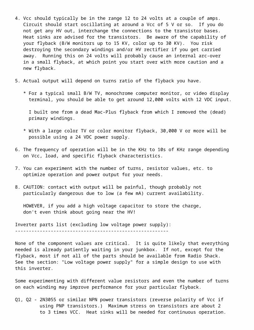
possible using a 24 VDC power supply.
6. The frequency of operation will be in the KHz to 10s of KHz range depending on Vcc, load, and specific flyback characteristics.
7. You can experiment with the number of turns, resistor values, etc. to optimize operation and power output for your needs.
8. CAUTION: contact with output will be painful, though probably not particularly dangerous due to low (a few mA) current availability.
HOWEVER, if you add a high voltage capacitor to store the charge, don't even think about going near the HV!
Inverter parts list (excluding low voltage power supply):--------------------------------------------------------
None of the component values are critical. It is quite likely that everythingneeded is already patiently waiting in your junkbox. If not, except for theflyback, most if not all of the parts should be available from Radio Shack.See the section: "Low voltage power supply" for a simple design to use withthis inverter.
Some experimenting with different value resistors and even the number of turnson each winding may improve performance for your particular flyback.
Q1, Q2 - 2N3055 or similar NPN power transistors (reverse polarity of Vcc if using PNP transistors.) Maximum stress on transistors are about 2 to 3 times VCC. Heat sinks will be needed for continuous operation.
R1 - 110 ohms, 2 W resistor (5 W for Vcc of 24 V). This provides base current to get circuit started.
R2 - 27 ohms, 5W resistor. This provides return path for base feedback during operation.
T1 - Flyback transformer from/for B/W TV, video display terminal, color TV, computer monitor, etc., modified according to text above.
Most modern flybacks include built-in HV rectifier diode(s) and/or voltage multiplier (tripler) so output without additional components will be high voltage positive or somewhat smoothed HV DC.
Note: this kind of flyback transformer drives the CRT directly and uses its glass envelope as the main high voltage filter capacitor. (A foot square piece of 1/8 inch Plexiglas with Aluminum foil plates makes a filter capacitor.)
Wire - a couple of feet of #16-#20 hookup wire, magnet wire, or any other insulated wire for home made primaries. Use electrical tape to fix windings to core. Wind feedback winding on top of drive winding.
Low voltage power supply:------------------------
The power supply (12 to 24 V) doesn't need to be anything fancy. Regulationis not needed so a simple power transformer-bridge rectifier-filter capacitor

design will be fine. The circuit described below will provide about 15 VDC atup to 3 A. Unless you are going for maximum output, this should be adequate.
During initial testing at least, a Variac on the input (or variable voltagepower supply) is highly desirable to avoid blowing anything should your wiringor parts not be quite right and to gain a feel for the capabilities of yourcircuit before it is too late! If neither of these is available, use a 10 ohm25 W power resistor or 100 W light bulb in series with the load (inverter) tolimit current to a safe value - one that won't fry too many things too quickly.
A typical circuit is shown below:
_ T1 H o-----o/ o---- _------+ 5 A diodes S1 Power F1 Fuse )|| or bridge 1 A )|| +---------+----|>|-------+-------+-----o +Vcc )||( ~| D1 |+ | )||( +----|<|----+ | +_|_ C1 115 VAC )||( 12 VAC D2 | | ___ 20,000 uF )||( +----|>|----|--+ - | 25 V )||( | D3 | | )|| +---------+----|<|----+----------+--+--o Gnd )|| ~ D4 - _|_ N o---------------------+ -
Low voltage power supply parts list:-----------------------------------
All of these are readily available.
T1 - 12 V, 3 A power transformer.S1 - SPST toggle switch.F1 - Fuse, 1 A.D1-4 - Silicon rectifier diodes, 5 A minimum. Or, 5 A bridge rectifier.C1 - Electrolytic filter capacitor, 20,000 uF or more, 25 V minimum. Typical flyback schematic:-------------------------
This diagram shows a typical flyback that might be found in a directview color television or computer monitor. Resistances are included forillustrative purposes only and may be quite different on your flyback!
The high voltage section on the right may actually be constructed as avoltage multiplier rather than a single winding with multiple HV diodes.The rectifiers or multiplier, and/or focus/screen divider may be externalto the flyback transformer in some models.
Flyback transformers used in black-and-white TVs and monochrome computermonitors do not have a focus and screen divider network.
The ferrite core of a flyback transformer is constructed with a precisiongap usually formed by some plastic spacers or pieces of tape. Don't losethem if you need to disassemble the core. The ferrite core is alsorelatively fragile, so take care.

The focus and screen divider network uses potentiometers and resistors(not shown) with values in the 10s to 100s of M ohms so they may notregister at all on your multimeter. The high voltage rectifiers (CR1to CR3 on this diagram) are composed of many silicon diodes in seriesand will read open on a typical VOM or DMM.
Note that there is no standardization to the color code. However, the fatwire to the CRT is most often red but could also be black. Of course, youcannot miss it with the suction cup-like insulator at the CRT anode end.
|:| +--|>|-----------o HV to CRT _ 1 |:|( CR1 (25 to 30 KV, | B+ o-------------+ |:|( suction cup on Drive | )|:|( fat red wire) winding < )|:| +-------+ | 1.32 )|:| | | 2 )|:| +--|>|--+ |_ HOT o-------------+ |:|( CR2 _ 3 |:|( | 50 o-------------+ |:|( | )|:| +-------+ | .11 4 )|:| | | 35 o-------------+ |:| +--|>|--+ Various | )|:|( CR3 | auxiliary < .28 )|:|( / windings | 5 )|:|( \<-------o Focus | 16 o-------------+ |:|( / (3 to 10 KV, | )|:|( \ orange wire) | .12 6 )|:|( | |_ 0 o----------+--+ |:|( 9 | _ | 7 |:| +--+ / | H1 o----------)--+ |:| | \<-------o Screen CRT Heater < .08 | 8 )|:| | / (200 to 800 V, |_ H2 o----------+--+ |:| | \ brown wire) | |:| | | | |:| +----|--------o To CRT DAG | | ground +----------------+
-- end V1.20 --
Understanding Flyback Transformer Pinout The Easy Way
Television and monitor flyback transformer pinout have some common designed except that the monitor flyback have internal capacitor built in. The internal capacitor value have around 2.7 nanofarad to 4.5 nanofarad to improve the picture quality especially when the monitor that can go for a higher resolution compare to Tv. If without the internal capacitor in the monitor flyback the display will curve or slightly out of shape especially at both the right and left hand side of the picture.
Mostly tv and monitor flyback transformers have about ten pins at the bottom of the flyback. Each of the pin have a purpose or function as part of a complete circuit. The common pins that you can find in monitor flyback are: B+ pin,

Horizontal collector pulse, ABL (automatic blanking limiter), GROUND, G1, AFC (automatic frequency control), VCC, HEATER (to filament) and X-RAY protection.
The B+ and horizontal collector pulse pin forms one winding which we call it as flyback primary winding. It can only can be test by using a flyback meter such as the Dick Smith Lopt tester or sencore LC102 and LC103C.Normal meters can't check this kind of fault. This is the most important winding compares to others and it can easily developed a short circuit when B+ voltage line or Horizontal output transistor (HOT) shorted. Sometimes a shorted internal capacitor in the flyback transformer may cause the primary winding to burn internally and the flyback became bulge and poured out the epoxy.
Other pins are the ground, G1, and AFC winding. AFC stand for automatic frequency control and it send signal (pulse) from the flyback transformer to the horizontal oscillator ic to lock or synchronize the frequency of the monitor. If this AFC line fails the picture will shift either to the far left or far right. There is no way that you can adjust the picture to the center even with the internal adjustment in the mainboard. The purpose of G1 voltage is to pull the electron generated from the cathode (after the heater or filament heat up) and passed it to G2 which is the screen voltage.
G1 normally is a negative voltage. Most tv picture tube do not use G1 voltage. If the G1 voltage is missing or zero voltage to the picture tube the monitor display will becomes very bright with retrace lines (diagonal lines or flyback lines) across the screen and sometimes the monitor will goes into shutdown mode.ABL stand for automatic blanking limiter- I refer it as a contrast circuit. Why? because whenever there is a contrast problem i will search for this pin and begin to trace from there. Normally a resistor increased in resistance and a shorted ceramic capacitor caused the display to become dim and you may think it might be the fault of a bad CRT.
Heater or filament pin nowadays hardly found in monitor flyback because the crt heater voltage now is derived directly from the switch mode power supply. However heater pin is still can be found in television flyback transformer. If the anode voltage is too high (more than 30 kilovolt), the x-ray protect pin will send a signal to horizontal oscillator ic in order to disable the horizontal drive waveform.
Without the horizontal drive pulse the high voltage generated by the flyback will collapsed and protect the user from excessive x-ray.
The flyback transformer pinout will also generate high pulse ac which later convert to dc through an ultra fast recovery diode. For your information, the ac pulse generated by the flyback transformer cannot be check with our normal analog or digital meter. the frequency is so high and you need a special meter to do the job. The dc voltages are then supply to various circuit such as the vertical output circuit. If you understand all the functions of each flyback transformer pinout, repairing monitor or tv will be much easier and save your precious time.
If you want to know more details about tv and monitor flyback transformer ,you may visit HRDIEMEN website and buy one of those CD that they offered. A little amount of investment can change the whole concept on how you look at a flyback transformer especially the pinout.

Testing of Flyback (LOPT) Transformers
Version 1.58 (19-Nov-06)
Copyright ©; 1994-2008 Samuel M. Goldwasser
--- All Rights Reserved ---
For contact info, please see the Sci.Electronics.Repair FAQ Email Links Page.
Reproduction of this document in whole or in part is permitted if both of the following conditions are satisfied:
1. This notice is included in its entirety at the beginning. 2. There is no charge except to cover the costs of copying.
Table of Contents
Preface o Author and Copyright o DISCLAIMER
Introduction o Scope of This Document
Safe Troubleshooting of Flyback Transformers Flyback (LOPT) Transformers
o What Does the Flyback (LOPT) Transformer Do? o How is a Flyback Transformer Different than a Regular Transformer? o The Origin of the Term, 'Flyback' o A Little History o Why is the Deflection and High Voltage Combined? o Flyback Construction o Why You Don't Want to Fabricate Your Own Flyback or Rebuild a Bad One
Flyback Failure and Testing o Why Do Flyback Transformers Fail? o How Do Flyback Transformers Fail?
Basic Testing o Initial Tests Using Your Senses and Perhaps a Multimeter o The Process of Elimination
Advanced Testing o When the Basic Tests Don't Reveal Anything o Method 1 o Method 2
Identifying the High Voltage Return on a Flyback Method 2 Testing Procedure
o Other Flyback Testing Procedures and Comments Additional Flyback Testing and Service Information
o Flyback Testing Equipment o Quickie In-Circuit Flyback Tests

o Testing for Bad High Voltage Diodes o Why Do All Flyback Transformers Seem to be Unique? o Typical Flyback Schematic o Replacement Flyback Transformers o Cheap flybacks - Beware
Back to Flyback Testing Table of Contents.
Preface
Author and CopyrightAuthor: Samuel M. Goldwasser
For contact info, please see the Sci.Electronics.Repair FAQ Email Links Page.
Copyright ©; 1994-2008 All Rights Reserved
Reproduction of this document in whole or in part is permitted if both of the following conditions are satisfied:
1.This notice is included in its entirety at the beginning. 2.There is no charge except to cover the costs of copying.
DISCLAIMERWe will not be responsible for damage to equipment, your ego, blown parts, county wide power outages, spontaneously generated mini (or larger) black holes, planetary disruptions, or personal injury that may result from the use of this material.
Back to Flyback Testing Table of Contents.
Introduction
Scope of This DocumentWhen problems develop in the horizontal deflection/high voltage subsystems of TVs or monitors (or even modern oscilloscopes and other CRT displays), the flyback transformer (or line output transformer for those on the other side of the Lake) is often a suspected cause. This is due in part to the fact that it is usually the most expensive and hard to find replacement part in the unit and because flybacks are often less well understood than other more common components.
This document addresses the operation and testing of flyback (LOPT) transformers: What they are, how they fail, why they fail, and how to test them. For more information on horizontal deflection systems, see the document: TV and Monitor Deflection Systems.

Back to Flyback Testing Table of Contents.
Safe Troubleshooting of Flyback Transformers
WARNING: Read, understand, and follow the recommendations in the document: Safety Guidelines for High Voltage and/or Line Powered Equipment before attempting any TV or monitor repairs.
In particular, before touching or probing the flyback or circuitry in its vicinity:
Unplug the equipment!!! Measure the voltage on B+ feed to the flyback and discharge the main filter capacitors if necessary. If going near the HV output, focus, or screen connections, discharge the CRT capacitance as well.
For specific information on safety for your equipment, see the documents: Notes on the Troubleshooting and Repair of Computer and Video Monitors or Notes on the Troubleshooting and Repair of Television Sets as appropriate.
Back to Flyback Testing Table of Contents.
Flyback (LOPT) Transformers
What Does the Flyback (LOPT) Transformer Do?The typical flyback or Line OutPut Transformer (LOPT) consists of two parts (you may also encount the term IHVT - Integrated High Voltage Transformer):
1. A special transformer which in conjunction with the horizontal output transistor/deflection circuits boosts the B+ (120 V typical for a TV) of the low voltage power supply to the 20 to 30 kV for the CRT as well as provides various secondary lower voltages for other circuits.
A HV rectifier turns the high voltage pulses into DC and the CRT capacitance smooths it. The HV may be developed from a single winding with many many turns of wire or a lower voltage winding and a diode-capacitor voltage multiplier.
The various secondary voltages power the logic, tuner, video signal, vertical deflection circuits, and CRT filaments. In fact, with many TV designs, the only power not derived from the flyback is for the keep-alive circuitry needed to maintain channel memory and provide startup drive to the horizontal deflection/high voltage system.
2. A voltage divider that provides the focus and screen supplies. The pots are in this divider network - and these things fail resulting in poor focus, uncontrolled brightness, or fluctuating focus and/or brightness. A total short could also result in failure of other components like the horizontal output transistor. The focus and screen are generally the top and bottom knobs, respectively. In some TVs, the focus and screen divider and/or controls are external to the flyback and susceptible to dust and problems particularly on damp days.

How is a Flyback Transformer Different than a Regular Transformer?While the following is not always strictly true for TV and monitor flyback transformers, it is a nice overview:
(From: Sivasankar Chander ([email protected]).)
1. The main difference between a flyback transformer and a regular transformer is that a flyback transformer is designed to store energy in its magnetic circuit, i.e., it functions like a pure inductor, whereas a regular transformer is designed to transfer energy from its primary to secondary and to minimize stored energy.
2. A flyback transformer in its simplest form has current flowing either in its primary, or in its secondary (but not both at the same time). (This is more complicated in practice because of finite turn-off times for transistors and diodes, need for snubber circuits, etc).
3. The reluctance of the magnetic circuit of a flyback transformer is usually much higher than that of a regular transformer. This is because of a carefully calculated air-gap for storing energy (it's an inductor).
4. The voltages applied to a flyback transformer on the primary side are almost always rectangular (pulsed) whereas regular transformers usually have sinusoidal voltages applied to them.
5. The currents flowing through either side of a flyback transformer are either increasing or decreasing linear sawtooths, whereas a regular transformer usually has sinusoidal currents.
6. Finally, due to the properties of core materials, flyback transformers are most conveniently operated in the range from 10^3 to 10^6 Hz, whereas regular transformers have a much wider range, from a few Hz to 10^12 Hz.
I may have succeeded in confusing you beyond redemption, so the best recourse for you would be to read any introductory textbook on switching power supplies for a more comprehensive picture.
The Origin of the Term, 'Flyback'In the U.S. (possibly all of North America), the transformer that generates the high voltage in a TV, monitor, or other CRT based equipment, is called the 'flyback' or 'flyback transformer'. Most everywhere else in the world, it is either LOPT (Line OutPut Transformer) or simply LOT, or as noted IHVT - Integrated High Voltage Transformer (which is actually the most accurate term for modern units).
The term 'flyback' probably originated because the high voltage pulse that charges the CRT capacitance is generated by the collapse of the magnetic field in the core of the transformer during the short retrace period - when the electron beam in the CRT 'flies back' to the start of a new scan line. The flux in the core changes slowly during scan and is abruptly switched in polarity by the HOT turning off during the flyback or retrace period.
Many off-line switchmode power supplies and DC-DC converters are also of the 'flyback' type with energy transferred to their output circuits mainly during the same time in the cycle - but there is no CRT involved. Indeed, these high frequency ferrite transformers - which generally look like regular transformers often of E-I core construction - may also be referred to as flybacks in transformer company catalogs.
LOPT and LOT derive from the fact that it is the line scan circuit that is involved and the transformer is in the output stage.
I still think flyback is much more quaint! :-).
Of course, others have their own definition:
(From: Sam Riner ([email protected]).)

When I was about 12 I touched the wire coming from the FBT on the picture tube, this was a BIG floor model TV, and I flew about five feet backwards. I know this isn't the real history for the name but for many years I believed it was.
A Little HistorySo, how far back does the use of a flyback based high voltage go?
(From: Henry van Cleef ([email protected]).)
A flyback HV supply was a feature of the 1946 RCA 630 and GE 801 sets. They used either an 807 or 6BG6 horizontal output tube, 6W4 damper, 1B3 rectifier.
The prewar TV's (yes, TV's were made and for sale before the NTSC standard was approved in 1941) generally used a 60 Hz. transformer and 2X2 similar to circuits used in RCA and Dumont oscilloscopes of the 1930's.
Zworykin/Morton "Television" (Wiley, 1940) has schematics and a project home-brew TV set using an 81 tube for the HV off a standard power transformer. Of course, to follow your way around this book, you have to know vacuum tube theory and a lot of physics reasonably well, but it is an historical gold mine.
(From: Brad Thompson ([email protected]).)
Some of the early TV sets used an RF oscillator to generate the high voltage for electrostatic-deflection CRTs: a typical tube lineup might include a 6V6 oscillator and 1B3 (or 1X2) rectifier.
Why is the Deflection and High Voltage Combined?One of the main reasons that TVs and many monitors are designed with horizontal deflection driven flybacks is simply economics - it provides a cheap way to get the high voltage and many or most of the other voltages for the set with minimal hardware. (High quality computer monitors sometimes use a separate high voltage supply so that the horizontal deflection is then used just for deflection to reduce interactions between changing scan rates and the HV.) A side benefit is that if the horizontal deflection dies, the HV power supply voltage goe with it and prevents the CRT phosphors from burning do to undeflected high intensity beam.
The use of the horizontal frequency rather than the AC line frequency of 50 or 60 Hz allows the power supply components to be small and light compared to a line operated power transformer and filter capacitors.
Flyback ConstructionWhile details can vary somewhat, all flybacks consist of a set of windings on a gapped ferrite core. High voltage diodes and resistive dividers (often with adjustment pots) for focus and screen (G2) may also be present.
A typical flyback includes the following components:
Drive winding - for a line powered TV, there will be perhaps a hundred turns of medium gauge (e.g., AWG #26) wire. For low voltage powered, it may only be a dozen turns of thicker wire. This is what is connected in series with the B+ to the horizontal output transistor in a TV or monitor.
High voltage winding - several thousand turns. This winding may be split into several series sections with a high voltage rectifier for each or could be a single winding. An alternative is provide a lower voltage winding and use a voltage multiplier (diode-capacitor ladder) to boost this to that required by the CRT. Very fine wire (e.g., AWG #40) will be used for the high voltage winding. The high voltage lead to the CRT is fed from the highest voltage output of the rectifier or multiplier.

Some TV and monitor designs use a physically separate (external - not part of the flyback transformer) voltage multiplier. In this case, the flyback high voltage winding will generate 6 to 10 kVAC and the multiplier will boost this typically 3X or 4X to 20 to 30 kVDC. The focus and screen (G2) network will generally be part of the multiplier module in this case.
Resistive divider network for focus and screen (G2). This will probably be fed from only one of the series connected windings (if used). Often, there are adjustments for focus and screen right on the flyback. The outputs from this divider may be connected to pins in the base of the flyback or have their own separate leads which connect to the CRT socket/board.
Auxiliary windings - anywhere from a couple of turns (for the CRT filament) to several hundred turns (for a boost source). These supply various voltages for the typical TV or monitor - CRT filament, logic power, analog power, boost source (where the flyback does not include its own screen supply), etc. The gauge of these windings will depend on the current requirements of each output. They are connected to solder pins at the base of the flyback.
Ferrite core - consisting of two C shaped pieces clamped together with either a spring arrangement or studs and nuts. There will be a gap of a fraction of a mm provided by a set of spacers between the two C sections.
Most modern flybacks have all the windings on the same leg of the core. The drive winding and auxiliary windings will be wound and separately insulated under the high voltage winding. The high voltage winding will consist of many layers which have insulating material (i.e., mylar) between them.
The other components will be mounted in a separate part of the assembly and the entire unit is then potted in an Epoxy type filler. Part of the core is generally accessible - often one entire leg.
A flyback is not an ordinary transformer. The ferrite core contains a gap. Energy is stored in the magnetic field of the core during scan as the current is ramping up. Energy is also coupled to certain secondary outputs during scan. However, energy for the high voltage (HV) is coupled to the its secondary windings almost entirely when the primary current is shut off at the end of the scan (probably the source of the name flyback because it is during the retrace of the electron beam).
Which type of coupling is in effect depends on the direction of the rectifiers on the secondary side of the flyback:
_ _ \/ _/\_ B+ ------+ +----|>|-----+---o +V1 B+ ------+ +----|>|-----+---o +HV o )::( o Scan | o )::( Flyback | )::( Rectifier _|_ )::( Rectifier _|_ )::( --- )::( --- )::( | )::( | _/\_ )::( | _/\_ )::( o | HOT ------+ +------------+ HOT ------+ +------------+ _|_ _|_ - -
Here, V1 is just a typical example of an auxiliary supply derived from a scan rectifier and HV is the best known example of the use of a flyback rectifier.
Note that the ratio of the number of turns for each winding *cannot* be used to calculate expected output voltages since the rate of collapse of the magnetic field (determined by the design of the horizontal output circuit) affects this.

The gap is critical to the proper operation and is usually determined by some plastic spacers. CAUTION: mark each one and replace them in exactly the same position if you disassemble the core for any reason.
Why You Don't Want to Fabricate Your Own Flyback or Rebuild a Bad OneAttempt to disassemble a flyback and you will understand why I don't recommend this unless the entire future of the explored *and* unexplored universe depends on the effort! You need specialized equipment to just wind the high voltage coil.
This isn't something you can do by hand in your basement and the only problem isn't the several thousand turns of nearly invisible wire used in a typical flyback. To sustain the high voltages without arcing and to minimize the interwinding capacitance, the high voltage winding is constructed as many individual layers - perhaps 50 layers in all - of 50 turns each using super fine wire (#40 typical - thinner than a human hair). Each layer must be wound perfectly flat with all wires side-by-side and then individually insulated with mylar tape. Just breathing on such wire will practically break it let alone wrapping several thousand turns in perfect order!
The other parts: drive and low voltage windings, focus and screen divider network, and high voltage rectifiers must be assembled with the high voltage winding and CRT leads and then the entire affair is potted in Epoxy.
Forget it - you have better things to do than spend a week on a transformer!
Back to Flyback Testing Table of Contents.
Flyback Failure and Testing
Why do flyback Transformers Fail?While flyback transformers can on occasion be blown due to a failure elsewhere in the TV or monitor's power supply or deflection circuits, in most cases, they simply expire on their own. Why?
Flybacks are wound with many layers of really really fine wire with really really thin insulation. This entire assembly is potted with an Epoxy resin which is poured in and allowed to cure.
In some ways, these are just short circuits waiting to happen.
Flybacks get hot during use and this leads to deterioration of the insulation. Any imperfections, nicks, or scratches in the insulation or trapped air bubbles and impurities in the Epoxy fill material contribute to failure. Temperature cycles and manufacturing defects result in fine cracks in the Epoxy potting material reducing the insulation breakdown particularly in the area of the high voltage windings, rectifiers, and focus/screen divider network. They also physically vibrate to some extent. A whole bunch of other factors are also no doubt important.
Once a breakdown - sparking or arcing - develops, it is usually terminal.
It is amazing they last as long as they do with the stresses they are under.
How Do Flyback Transformers Fail?Flybacks fail in several ways:

1. Overheating leading to cracks in the plastic and external arcing. If there is no major damage to the windings, repair may be possible. However, arcing from the windings punctures their very thin insulation so that shorted windings may already have developed. Even if the windings are currently in good condition, long term reliability of any such repairs is questionable.
Nonetheless, it doesn't hurt to try cleaning and coating with multiple layers of high voltage sealer, corona dope, or even plastic electrical tape (preferably as a temporary repair though I have gotten away with leaving this in place permanently). If possible, moving the point to which the flyback is arcing further away (i.e., a piece of metal or another wire) would also help.
(The following from: Tom Riggs ([email protected]))
For sealing flyback transformers, I have found that silicone sealer has worked very well. I used the clear variety, though others will probably work as well. I have heard of burn through with corona dope. (Author's note: make sure you allow ample time for the silicone sealer to setup completely - or else it will breakdown instantly - at least 24 hours. Also, some types (those that smell like vineger - acetic acid - as they cure may result in corroded wiring in the long term).
2. Cracked or otherwise damaged core will effect the flyback characteristics to the point where it may not work correctly or even blow the horizontal output transistor and other expensive parts like the low voltage regulator or switchmode power supply. If the core can be reconstructed so that no gaps (other than the required ones where the two halves join) are present and clamped and/or glued in place, it should be possible to perform testing without undue risk of circuit damage but consider a replacement flyback as a long term solution.
3. Internal shorts in the FOCUS/SCREEN divider network, if present. One sign of this may be arcover of the FOCUS or SCREEN spark gaps on the PCB on the neck of the CRT.
4. Internal short circuits in the windings. 5. Open windings.
More than one of these may apply in any given case. As noted, temporary repair, at least, is sometimes possible for failures (1) and (2). For failures (3) to (5) replacement is usually the only alternative.
Back to Flyback Testing Table of Contents.
Basic Testing
Initial Tests Using Your Senses and Perhaps a MultimeterFirst, perform a careful visual inspection with power off. Look for cracks, bulging or melted plastic, and discoloration. Look for bad solder connections at the pins of the flyback as well. If the TV or monitor can be powered safely, check for arcing or corona around the flyback and in its vicinity, or at the sparkgaps or gas tube protectors on the CRT neck board.
Next, perform ohmmeter tests for obvious short circuits between windings, much reduced winding resistances, and open windings. Don't neglect to check between the CRT HV connector (suction cup) and the pins on the base. This should measure infinity.
For the low voltage windings, service manuals may provide the expected DC resistance (Sams' Photofact, for example). Sometimes, this will change enough to be detected - if you have an ohmmeter with a low enough scale. These are usually a fraction of an ohm. It is difficult or impossible to measure the DC resistance of the HV winding since the rectifiers are usually built in. The value is not published either.

WARNING: Make sure you have the TV or monitor unplugged and confirm that the main filter capacitor is discharged before touching anything as the flyback is usually connected to this point, perhaps directly! If you are going to remove or touch the CRT HV, focus, or screen wires, discharge the HV first using a well insulated high value resistor (e.g., several M ohms, 5 W) to the CRT ground strap (NOT signal ground).
Measurements that are much less than the published values likely indicate a partially shorted winding. However, a difference of 10% may not be at all significant. Higher than normal readings might simply indicate that a design change was made. Yes, I know, hard to believe they would not have informed you of this! For example, various versions of the flyback used in the Apple MAC Plus - 157-0042A,B,C - are functionally similar but have minor variations in winding parameters. It is not known what effects this would have but they are interchangeable at least for testing.
Of course, any continuity between separate windings is definitely a fault.
Partially short circuited windings (perhaps, just a couple of turns) and sometimes shorts in the focus/screen divider will drastically lower the Q and increase the load the flyback puts on its driving source with no outputs connected. It is these types of failures, not detectable by simple ohmmeter tests or visual inspection, which the techniques described in the sections under "Advanced testing" address.
While less common, I have seen shorts between the CRT HV connector and the low voltage windings on the base of the flyback. This implies a breakdown of the Epoxy potting material probably due to thermally induced microcracks or poor quality manufacturing. Once a small arc develops, it rapidly carbonizes the material around it further reducing the resistance. These rarely heal themselves and thus show up as obviously low resistance readings using an ohmmeter. It is an easy test and can be performed without removing the flyback. Discharge the CRT HV (though this will probably be dead) and just remove the connector from the CRT.
It is also possible that various types of flyback faults can damage other circuitry (beyond taking out the horizontal output transistor and its associated parts). For example, a sudden short between the CRT HV connector and a low voltage winding or a short between two low voltage windings could conceivably blow solid state components powered from the flyback. This damage will generally not be apparent until the flyback is replaced. Therefore, if shorts are detected in the flyback, it is worth testing some of the components in the vicinity and vice-versa.
The Process of EliminationBefore attempting the more advanced tests suggested below, there may be ways of being more certain that your flyback is the problem component. The following assumes that running the TV or monitor with the suspect flyback results in an excessive load on the low voltage (B+) power supply blowing a fuse (or attempting to blow a fuse - excessively bright series light bulb). The B+ likely drops from its normal 65 VDC to 140 VDC or more (depending on the actual TV or monitor and mode) to some low value like 25 VDC when measured on the low voltage power supply side of the flyback drive winding. (Measuring at the HOT can result in all sorts of weird readings due to the pulse nature of the waveform and is not recommended - especially when everything is working properly - 1,500 V pulses!).
Disconnect all the secondary loads from the suspect flyback including the CRT. Connect only the drive (B+ and HOT).
Power up the TV or monitor (preferably with a series light bulb or on a Variac.
If the B+ now climbs to a more normal value, a problem with the HV (CRT short) or one of the secondary loads is indicated. Connect each of these up one a time (or test individual components) to localize the fault. The flyback is likely good.

Remove the suspect flyback and connect just the HOT and B+ to the drive winding of a known good flyback for a similar size TV or similar type of monitor (as appropriate). It may be close enough to keep the drive circuitry happy.
Power up the TV or monitor (preferably with a series light bulb or on a Variac.
If the B+ now climbs to a more normal value, a problem with the original flyback is indicated. However, more thorough testing may be desirable to be absolutely certain.
If you do this regularly, keeping a selection of 'flyback simulators' - just the drive windings and cores may be desirable.
Back to Flyback Testing Table of Contents.
Advanced Testing
When the Basic Tests Don't Reveal AnythingAlso see the section: Flyback Testing Equipment.
There are several ways of testing flybacks (assuming you do not actually have special test equipment for this purpose). Here are two possibilities. The first is easier if you have a scope but the second is more fun.
Method 1The following technique, called a 'ring test', works for flybacks, chopper transformers, motors, mains transformers, deflection yoke windings, VCR video and other magnetic heads, and other transformers, coils, or inductors.
However, note that it can miss certain problems like open windings (if they are not used for the test) as well as shorts or opens that occur only when the flyback is driven near full voltage. Thus, do the basic tests FIRST and don't assume that the flyback is 100 percent good just because it passes the ring test (though the likelihood of this is very high).
(Portions from: Gabe ([email protected]).)
This is called a 'ring test' and is the method often used by commercial flyback (or other coil/transformer) testers. The theory is that a faulty flyback (which cannot be found by simple resistance measurements) will have shorted turns in one of the coils. In such a case, the 'Q' of the transformer is greatly reduced. If excited by an impulse, a faulty transformer will resonate with a highly damped oscillation while a good one will decay gradually.
1. Connect a high quality capacitor across one winding of the suspect device. Hope for a resonant frequency of a few kHz. You may need to select the capacitor value for best results. I have found that a capacitor in the .001 uF to 1 uF (non-polarized) will usually be satisfactory.
Note that it doesn't matter whether the excitation is applied to the shorted winding or any other one. However, you should avoid trying to connect the generator to one of the very small windings like those for the CRT filament which may only have 2 or 3 turns.

2. Apply a pulse waveform to the parallel resonant circuit. In 1960, most scopes had a 'sync out' on the timebase that provided a few 10s of volts at enough current for this. A circuit in "Television" magazine a couple of years ago used a BU508, a 12 V power supply, and a small oscillator built from a 4011 chip. A function generator or a 555 timer based circuit will also make a satisfactory stimulous. Also see the section: Flyback Testing Equipment.
3. Look at the waveform across the resonant circuit with a 'scope. A good unit will give a nicely decaying oscillation, of at least a few cycles, possibly 10's of cycles. If there is a shorted turn *anywhere* in the device, the oscillations will be seriously damped, and you'd be lucky to see 2 complete cycles. Experience and/or comparison with a known good device will tell you what to expect.
4. Scope5. _ o6. Pulse or _| |_ | Device under Test7. function o---------------------+-----------+ +---8. Generator | )::(9. High Quality _|_ )::( All other10. Non-polarized --- ):: +--- windings11. Capacitor | ):: +--- left open12. | )::(13. Ground o---------------------+-----------+ +---14.
(From: James Elliott ([email protected]).)
I tried the Q evaluation method using the 100 volt CAL voltage pulse from a Tektronix scope. It worked best when I used a series 200 pF capacitor. I got maybe 100 pulses before it decayed to zero. If I shorted two of the primary pins, the decaying pulse train went to zero almost immediately. So it works!
I thought of another method. The Q of a resonant circuit is equal to the center frequency divided by the half power bandwidth. I applied an audio generator through a 22k resistor, found the peak frequency, then went off that frequency to .707 of that amplitude. Double this would be the bandwidth. I got Q's of 26 and 16 for two I tried. (Editor's note: This appears to be a valid approach.)
Method 2
The circuit below excites the flyback in much the same way as in normal operation. The only caution is that this tester probably does not put enough stress on the flyback to find an intermittent that fails only under full operating conditions. However, most flyback failures are solid - once a short develops, there is a meltdown of sorts and it is there to stay.
You will require a 12 V power source of at least 2 or 3 amps capacity (regulation is not important - I just use a simple transformer, rectifier, filter capacitor type of power supply).
The circuit is shown below. None of the component values are critical.
+12 Q1 +----------------+ o | ):: | B |/ C ):: <-- Flyback Under Test --> | +------| 2N3055 ):: | | |\ E 5T ):: +------|>|----------o +HV | | | ):: ::( HV Diode(s), | | -_- ):: ::( usually built in. | | ):: +-----+ ::( +--|-------------------------+ ::( )::( | | Q2 _-_ )::( 10T )::( | | | )::( each )::( | | B |/ E 5T )::( _ )::( | | +---| 2N3055 )::( _|_ )::(

| | | |\ C ):: +-- --+ ::( | | | | ):: Switch ::( | | | +----------------+ :: ::( | | | :: ::( | | -----------------------+ :: +------------------o -HV | | 2T ):: | | +-----------+ :: (Numerous other windings not shown.) | | | 2T ):: | +-------------------------+ Note: :: denotes ferrite core. | | | R1 | R2 +--------/\/\/\--+--/\/\/\---+ 110 27 _|_ 2W 5W -
Note: if the circuit does not start oscillating at about 5 volts or less, interchange the two feedback connections to the transistor bases.
The tester is just a chopper feeding the salvaged core from an old flyback (I removed the inductance control spacers for this core). The drive (5T+5T) and feedback (2T+2T) coils can be wound from hookup wire (#14-#20) and well insulated with plastic electrical tape. Connect the center taps directly to the coils - do not bring out a loop of wire. Make sure all the turns of each coil are wound in the same direction. Wind the feedback coil directly on top of the drive coil. The secondary of this core is a 10 turn well insulated coil similar to the other two wound on the opposite side of the ferrite core.
You will need to remove the suspect flyback from the TV or monitor. Another 10 turn coil is wound on the suspect flyback core anywhere it will fit. Connect one end of this coil to one end of the 10 turn coil on your old flyback core. Use a wire nut or twist together securely. Provide an easy way of connecting the other ends momentarily - a pushbutton comes in handy.
Make sure you locate the HV return lead on the flyback and use that as the return for the arc. Otherwise, you may puncture the insulation when the high voltage finds it own path to ground.
Identifying the High Voltage Return on a FlybackIt is essential that this be correctly connected or else the high voltage *will* find a suitable path to ground - and it may not do the other circuitry any good!
There are several approaches that can be taken - possibly in combination:
Process of elimination - the HV return will often be an isolated pin on the flyback not connected to anything else. Therefore, if you test between all combinations of pins on the flyback (removed from the circuit board) and find a pin that appears open to all other pins but is connected to a pad on the circuit board, it is quite likely the HV return.
Check all connections on the circuit board and identify those that go to ground. One of these flyback pins will be the HV return. It will do no harm to connect them all to ground during testing.
Use a 100 VDC or greater power supply and high value resistor, say 100K. Connect the power supply negative output through this resistor to the HV lead on the flyback (suction cup connector):
100K PS- o--------/\/\--------+--------o CRT (suction cup) connector on flyback | o - 100 VDC Measure voltage here +

o | PS+ o---------------------+--------o Probe to pins on base of flyback
Check each pin on the base of the flyback with the probe. Touching the return pin will result in the voltage reading dropping to perhaps 50 or 60 volts. This is the forward voltage drop across the high voltage rectifier stack inside the flyback. All other pins will result in it remaining at the supply voltage (except for the ground connection to the F/G2 divider if it is separate - then it may drop a fraction of a volt). Note that if you cannot locate the HV return, your flyback may indeed be defective; it may have an internal bad connection, open HV rectifier, or burnt out HV winding. Or, if other pins drop the voltage, you may have already found shorts in the flyback!
Method 2 Testing ProcedureOnce everything is wired and double checked, turn on the juice.
If the flyback is good, then with the coils connected there will be several kV at its output - enough to create a small arc (1/8" typical, up to 1/2" for color flybacks).
The load imposed on the oscillator will be modest (the frequency increases in response to load).
If there are any shorted windings, then there will be no significant HV output and the load on the oscillator will increase dramatically.
If you get arcing or corona from *under* the flyback - at the pins - either did not locate the correct HV return or there is a short inside resulting in HV arcing internally to the low voltage windings.
I have used this 'tester' on a dozen or so flybacks. It has never been wrong (though I have opted not to believe it and gotten screwed).
Other Flyback Testing Procedures and CommentsHere is a Web site with some notes on flyback testing procesures:
Noahtech Testing Flyback Transformers - How To Test And When To Replace it
They have other useful information related to monitor repair as well as well as many links back here!
(From: Terry ([email protected]).)
I first check for HOT shorts, secondary supply overloads, and everything else, disconnecting the flyback windings to any suspect circuits as I go. So, if I get to the following test, pretty much all connections to the flyback are now open anyway. Next, I perform "The Loop Test":
1. Ring the transformer at the HOT primary winding. You don't need fancy signal generators to inject a signal. Even the 60 Hz AC secondary from a 6 volt filament transformer will work, although you date yourself if you have one in your shop. (Note: I expect that the 6 VAC transformer works in this case because the core of the flyback saturates pretty quickly at this low frequency resulting in sharp edges to produce the ring pulse - I would rather use a 555 timer or pulse generator --- Sam.)
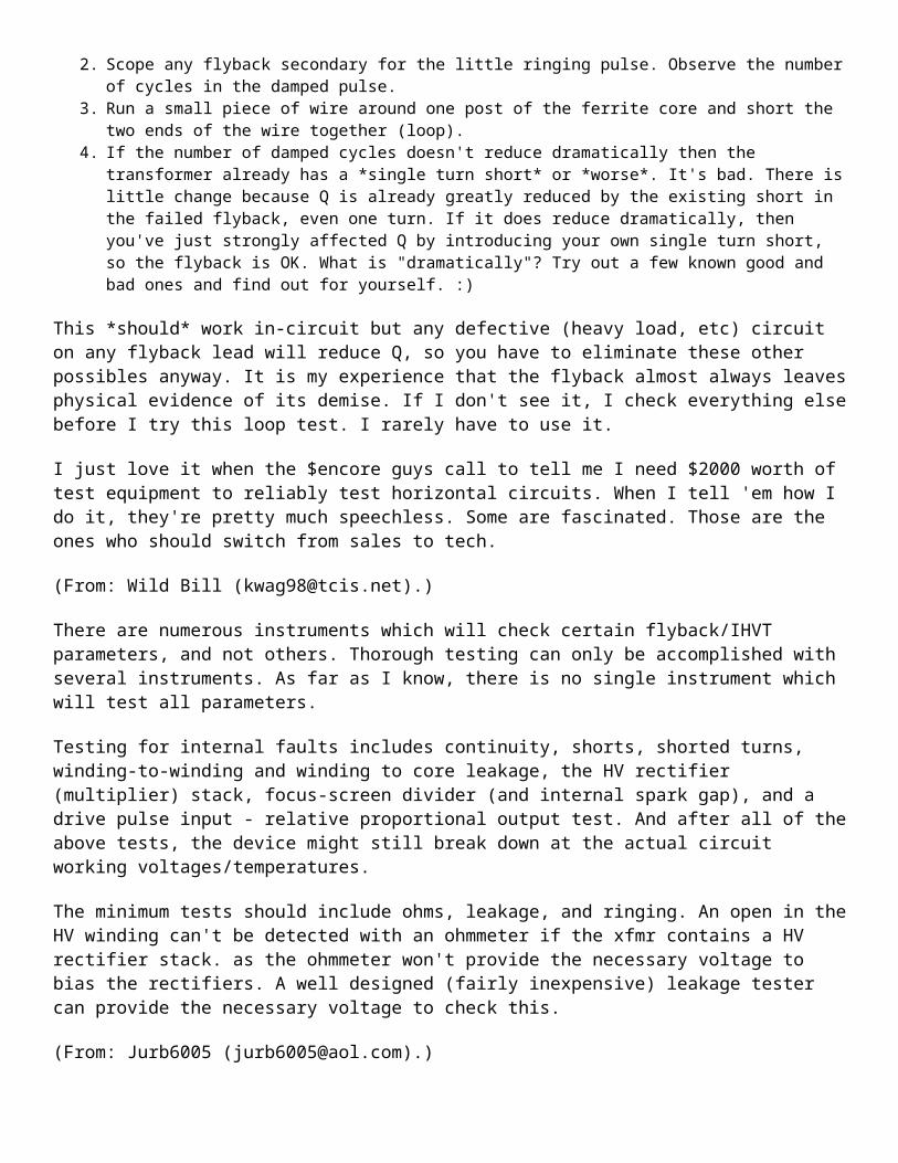
2. Scope any flyback secondary for the little ringing pulse. Observe the number of cycles in the damped pulse. 3. Run a small piece of wire around one post of the ferrite core and short the two ends of the wire together (loop). 4. If the number of damped cycles doesn't reduce dramatically then the transformer already has a *single turn
short* or *worse*. It's bad. There is little change because Q is already greatly reduced by the existing short in

the failed flyback, even one turn. If it does reduce dramatically, then you've just strongly affected Q by introducing your own single turn short, so the flyback is OK. What is "dramatically"? Try out a few known good and bad ones and find out for yourself. :)
This *should* work in-circuit but any defective (heavy load, etc) circuit on any flyback lead will reduce Q, so you have to eliminate these other possibles anyway. It is my experience that the flyback almost always leaves physical evidence of its demise. If I don't see it, I check everything else before I try this loop test. I rarely have to use it.
I just love it when the $encore guys call to tell me I need $2000 worth of test equipment to reliably test horizontal circuits. When I tell 'em how I do it, they're pretty much speechless. Some are fascinated. Those are the ones who should switch from sales to tech.
(From: Wild Bill ([email protected]).)
There are numerous instruments which will check certain flyback/IHVT parameters, and not others. Thorough testing can only be accomplished with several instruments. As far as I know, there is no single instrument which will test all parameters.
Testing for internal faults includes continuity, shorts, shorted turns, winding-to-winding and winding to core leakage, the HV rectifier (multiplier) stack, focus-screen divider (and internal spark gap), and a drive pulse input - relative proportional output test. And after all of the above tests, the device might still break down at the actual circuit working voltages/temperatures.
The minimum tests should include ohms, leakage, and ringing. An open in the HV winding can't be detected with an ohmmeter if the xfmr contains a HV rectifier stack. as the ohmmeter won't provide the necessary voltage to bias the rectifiers. A well designed (fairly inexpensive) leakage tester can provide the necessary voltage to check this.
(From: Jurb6005 ([email protected]).)
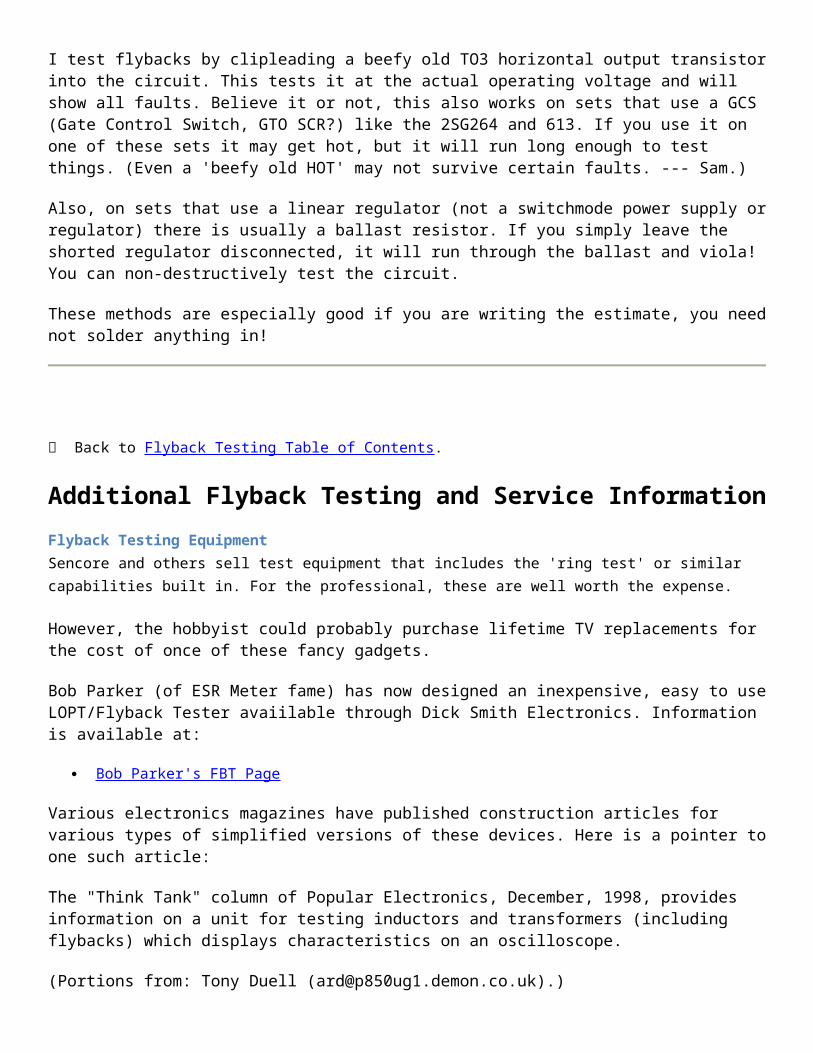
I test flybacks by clipleading a beefy old TO3 horizontal output transistor into the circuit. This tests it at the actual operating voltage and will show all faults. Believe it or not, this also works on sets that use a GCS (Gate Control Switch, GTO SCR?) like the 2SG264 and 613. If you use it on one of these sets it may get hot, but it will run long enough to test things. (Even a 'beefy old HOT' may not survive certain faults. --- Sam.)
Also, on sets that use a linear regulator (not a switchmode power supply or regulator) there is usually a ballast resistor. If you simply leave the shorted regulator disconnected, it will run through the ballast and viola! You can non-destructively test the circuit.
These methods are especially good if you are writing the estimate, you need not solder anything in!
Back to Flyback Testing Table of Contents.
Additional Flyback Testing and Service Information

Flyback Testing EquipmentSencore and others sell test equipment that includes the 'ring test' or similar capabilities built in. For the professional, these are well worth the expense.
However, the hobbyist could probably purchase lifetime TV replacements for the cost of once of these fancy gadgets.
Bob Parker (of ESR Meter fame) has now designed an inexpensive, easy to use LOPT/Flyback Tester avaiilable through Dick Smith Electronics. Information is available at:
Bob Parker's FBT Page
Various electronics magazines have published construction articles for various types of simplified versions of these devices. Here is a pointer to one such article:
The "Think Tank" column of Popular Electronics, December, 1998, provides information on a unit for testing inductors and transformers (including flybacks) which displays characteristics on an oscilloscope.
(Portions from: Tony Duell ([email protected]).)
The February 1998 issue of 'Television' magazine, has a simple circuit for an LOPT (Line Output Transformer - flyback transformer) tester.
It uses a TBA920 chip as an oscillator, driving a BUT11AF which supplies the primary of the LOPT. The voltage developed across this winding (the back EMF when the transistor is turned off) is shown on a DMM. There's also a 'scope point to look at the waveform produced.
Another chip or an oscillator constructed from discrete transistors can be substituted for the TBA920. Some possibilities: 555 timer or MC1391, or a multivibrator can be built from 2N3904s.
However, there are a few errata in the article:
1. The supply voltage is 12 V as mentioned in the text, not 2 V as shown on the schematic. 2. The peak amplitude given in fig. 3 of 8 V should be after the divider network, not at the transformer itself. 3. There is a capacitor shown from pin 13 (decoupling) which almost certainly should be a bypass to ground, not to
the collector of the drive transistor.
Quickie In-Circuit Flyback TestsNote: Larry has 'beta tested' Bob Parker's (of ESR meter fame) flyback tester described at: http://www.ozemail.com.au/~bobpar/fbt.htm.
(From: Larry Sabo ([email protected]).)
Checking out flybacks can be frustrating and very time consuming without a good tester.
Now, it just takes me a second to check for ringing on the HOT collector. No ringing? Check the HOT with a DVM for shorts. No shorts? Unsolder all flyback legs except the primary winding and check for rings again. No rings? Shorted turns in the flyback!

Bob's estimate that 20% of faulty flybacks have internal leakage or arcing, or bad HV diodes, seems about right. And an LC102 (tester) won't catch these either :-). I've found that about half of these show up with a low resistance measurement between the EHT cap and ground.
Sometimes scoping the output at the EHT cap shows unrectified ringing but stray capacitance probably accounts for that. Other times, it's clearly rectified, so go figure. As a last resort, I resort to Sam's chopper to wrestle the hold-outs to the ground, but it takes a bit of time to remove the flyback and put 10-15 turns around the core. The ringer has also helped me isolate a defective yoke, which explained why things wouldn't ring.
Anyway, I think Bob's tester is a great little unit and am glad I have had the opportunity to test it--and keep the prototype! :-)
(From: John Robertson ([email protected]).)
I use an audio signal generator set it to about 15 kHz and a scope or AC voltmeter on one of the output windings.
Connect the generator to the leads that the horizontal output transistor and ground use (out of circuit, use HOT and B+ leads --- sam). You should see on the scope a reasonably nice waveform similar to the input. If you are using a voltmeter, you should get approximatly the correct ratio output voltage relative to the original voltages. So if your generator puts out 10 VAC and the original HV input levels were 100 VDC, then the voltage levels should be about 1/10th of the original. I do this in-circuit, and try to get a square wave as the source, but the theory is consistant.
(From: Quick Fix ([email protected]).)
If you don't don't repair that many TVs, the cheapest way to check a FBT is to connect its primary winding in series with the yoke (low side) of a working set. If the picture shrinks a few inches on both sides evenly and with no ringing or jail bars, your FBT is good. You can even measure the high voltage on your FBT with this method.
Testing for Bad High Voltage DiodesA single diode failure would be tough to find if it is in series with other diodes (as is typical on larger flybacks) as it would only be a problem when run near full output. However, this sort of failure is unlikely.
General diode failure (shorts) would probably not be detected with the sorts of tests described above or with typical flyback testing equipment. Actually, a simple ohmmeter test between the HV output and return might suffice! If this doesn't reveal anything, I suggest the following:
One possible way to test for this would be to attach a high voltage capacitor between the HV output and return of the flyback. If the diodes are good, the tester's excitation should then charge this cap up (watch out - the voltage might get to be quite high!). While charging, this load will make the flyback fail any ring test. Once charged, it should pass. However, if the diodes are shorted, I would expect the flyback to test bad as the cap will continue to present an AC load on the output and never charge properly.
I haven't tried this, however, so no guarantees.
(From: dB King (([email protected]).)

Sencore Z-Meters are capable of applying sufficient bias to check those diodes for forward conduction and reverse leakage. Forward conduction should be confirmed first to rule out an open -- almost all multimeters will always show open HV diodes due to their limited voltage output.
Indispensable for capacitor tests as well. I dunno how I got by w/o mine! They also have built-in yoke/flyback ringer. :)
Quite expensive. You might wanna try to find a used one.
Why Do All Flyback Transformers Seem to be Unique?(Most of these comments also apply to SMPS high frequency transformers.)
Of all the components in a monitor or TV, the flyback is very likely to be a unique part. This is not so much due to the high voltage winding and/or HV multipler but rather related to its usual function as the source of multiple secondary power supply voltages used by various tuner, deflection, video, and audio subsystems. In addition, inductance, capacitance, pin configuration, and HV, focus, and screen outputs must be compatible.
ECG and similar companies do have a line of generic FBTs and should have a catalog/cross reference for these similar to the one for semiconductors. See the section: Replacement Flyback Transformers.
However, FBTs are where the designers of TVs and monitors can be really creative. After all, specifying the flyback windings gives them complete freedom to pick the number and types of secondary voltages! Your chances of picking up something off the street so-to-speak and expecting it to fit anything you have ever owned - or ever will own - isn't great.
(From: an engineer at a TV manufacturer).
We have one guy whose mission in life is doing exactly that... (and specifing HOT's too).
Besides specifying auxiliary secondaries you can also specify an overturn on the primary (for deflection coils which would otherwise require a >1500 V HOT) and influence the tuning of the EHT secondary, to determine the EHT internal impedance. And finally you might specify a built-in EHT capacitor or bleeder resistor and various types of clicked-on potmeter modules (perhaps with a second focus voltage for DAF).
Typical Flyback SchematicThis diagram shows a typical flyback that might be found in a direct view color television or computer monitor. Resistances are included for illustrative purposes only and may be quite different on your flyback!
The high voltage section on the right may actually be constructed as a voltage multiplier rather than a single winding with multiple HV diodes. The rectifiers or multiplier, and/or focus/screen divider may be external to the flyback transformer in some models.
Flyback transformers used in black-and-white TVs and monochrome computer monitors do not have a focus and screen divider network. Older ones do not include a high voltage rectifier either - it is external.
The ferrite core of a flyback transformer is constructed with a precision gap usually formed by some plastic spacers or pieces of tape. Don't lose them if you need to disassemble the core. The ferrite core is also relatively fragile, so take care.

The focus and screen divider network uses potentiometers and resistors (not shown) with values in the 10s to 100s of M ohms so they may not register at all on your multimeter. The high voltage rectifiers (CR1 to CR3 on this diagram) are composed of many silicon diodes in series and will read open on a typical VOM or DMM.
Note that there is no standardization to the color code. However, the fat wire to the CRT is most often red but could also be black. Of course, you cannot miss it with the suction cup-like insulator at the CRT anode end. The focus and/or screen connections may also be to pins rather than flying leads.
+--|>|-----------o HV to CRT _ 1 ::( CR1 (25 to 30 kV, | B+ o-------------+ ::( suction cup on Drive | )::( fat red wire) winding < ):: +-------+ | 1.32 ):: | | 2 ):: +--|>|--+ |_ HOT o-------------+ ::( CR2 _ 3 ::( | 50 o-------------+ ::( | ):: +-------+ | 4 .11 ):: | | 35 o-------------+ :: +--|>|--+ Various | )::( CR3 | auxiliary < .28 )::( / windings | 5 )::( \<-------o Focus | 16 o-------------+ ::( / (3 to 10 kV, | )::( \ orange wire) | 6 .12 )::( | |_ 0 o----------+--+ ::( | _ 7 | :: +--+ / | H1 o----------|--+ :: | \<-------o Screen CRT Heater < 8 .08 | ):: | / (200 to 800 V, |_ H2 o----------+--+ | \ brown wire) | | | 9 | +----|--------o To CRT DAG | | ground +---------------+
Replacement Flyback TransformersUnfortunately, you cannot walk into Radio Shack and expect to locate a flyback for your TV or monitor. It is unlikely the carrots at the counter will even know what a flyback is or recognize one if it hit them over the head (wherever that would be on a carrot). They will probably attempt to sell you a 6.3 V power transformer :-). Fortunately, there are other options:
Original manufacturer - most reliable source but most expensive. Older models may not be available. This may be the only option for many TVs and monitors - particularly expensive or less popular models.
Electronics distributors - a number of places including MCM Electronics, Dalbani, Premium Parts, and Computer Component Source, sell replacement flybacks. See the document: Notes on the Troubleshooting and Repair of Computer and Video Monitors for contact info. Many of these are actually original parts and are designated as such. However, there may be no way of knowing and you may end up with something that isn't quite compatible (see below). Thus, unless the catalog listing says 'original part', these may be no better than the sources below.
Here is one apperently just for flybacks:
o Component Technologies, 1-888-FLYBACK or 1-800-878-0540. email: [email protected].

and one that is mostly for flybacks:
o CRC Components, 1-800-822-1272.
some others:
o Data Display Ltd, Canadian sub of CCS, 1-800-561-9903. o EDI (Electro Dynamics, Inc.) NY, 1-800-426-6423.
And, here's one for your semi-antique (1950s) needs:
o Linear Electronics, Walthan, MA. Phone: 1-617-894-7300, Fax: 1-617-894-8890. (They also have vacuum tubes.)
Generic replacements - these are sometimes available. ECG, NTE, ASTI, HR Diemen, for example, offer a line of replacement flybacks. Some of these sites include a cross reference to their replacement based on TV or monitor model and/or the part or house number on the flyback:
o NTE (NTE Electronics, Inc) o ECG (Philips) (now same as NTE) o HR (HR Diemen) o ASTI (ASTI Magnetics) o Flybacktransformer
However, these may be of lower quality or not be quite compatible with your original. In an effort to minimize the number of distinct flyback models, some corners may be cut and one-size-fits-many may be the rule resulting in all sorts of problems. Here are a couple of possibilities:
o The number of turns on one or more windings may not quite match your original meaning there will be lower or higher voltages from certain outputs and/or drive conditions (current, resonance) may be affected.
o There may even be extra or missing connections - pins on the bottom or flying leads. It is essential to determine what must be done to make the flyback work in your equipment *before* applying power. Extra connections may need to be grounded or connected to some other points in the circuit. If this is not done, operation may not be correct or other parts may blow as current from these unconnected pins finds its own way to ground.
o The flyback may simply be defective due to bad quality control, part number confusion, or mismarking. Internal circuitry such as the focus and screen(G2) divider could be improperly wired, configured for a different model, or omitted entirely. Such defects can be very tough to identify.
Thus, marginal or erratic behavior might result from generic replacements greatly complicating your troubleshooting since without careful measurements there is no way of knowing whether the problem is due to the new flyback or a fault that still exists elsewhere. For some actual experiences, see the section: Cheap Flybacks - Beware.
(From: [email protected].)
HRdiemen is a manufacturer of replacement line output transformers and have several thousand types available. But the nicest thing is their online database where they have pinout and internal schematics including typical voltages of every of these transformers. Just type your original letters/numbers into the search box, then you get the replacement transformer type and a link to its internal construction.
Very helpful if you want to "recycle" an old transformer for a new circuit.
Javascript must be enabled for this to all happen automagically. If you prefer to work without javascript (like me, to avoid ad banners and other doubtful background activities), you can also directly access http://www.hrdiemen.es/data/esquemas/HR7491.gif or whatever number your transformer has.
Cheap flybacks - BewareThere have been reports of inexpensive replacement flybacks resulting in a variety of strange symptoms. I do not know how likely it is to have problems with these. In most cases, I would expect the replacement to drop right in and perform perfectly. However, I have heard of occasionally difficulties. I do not know which, if any, of the companies listed above sell such incompatible devices. However, it would be worth checking before buying if possible.
Here are several examples of incompatibility problems:
(From: Petercoe ([email protected]).)
There is some good and some bad to these flybacks. One thing I noticed is that the competition has caused the price of the name brands to drop.
However, these flybacks may not work right in all cases. I know I had to modify a circuit in a Sony to get the set to work right after using a low priced replacement. I also had a Goldstar which would only work with the original flyback."
(From: Michael Caplan ([email protected]).)
The FBTs that I tried (three samples in two generic brands available here in Canada) all seem to be missing the required internal voltage divider. This was confirmed by comparison with a new oem Sony part. The OEM part exhibits the proper resistance measurement. It is through this resistance that the Hold Down voltage is derived. "No resistance = no Hold Down voltage", as far as I can see."
(From: Dave Moore ([email protected]).)
I recently put a cheapo sub flyback Hitachi P/N 243384 in a Hitachi model CT2647 26" tv.
Apart from inadequate horizontal deflection, the TV exhibited ringing like jail bar shadows on the left side of the screen and a bright area with retrace lines showing from top to bottom down the middle of the of the screen. At first I thought that this was the classic bad B+ filter to the crt board phenomena. But nope, filter good.
So I figured that it had to be a bad filter in the brightness limiter or to the video circuits. A quick round about with my trusty DS ESR meter did sniff out a weak cap in what seemed to be the brightness limiter circuit. Did this cure the problem? As John Belushi would say: Nooooooooooooo. Well I recalled a similar problem that I had encountered while experimenting with the screen voltage on a Zenith TV. At one point I had removed a small disk capacitor on the screen supply trying to unload the shorted screen supply. Well the problem turned out to be the picture tube and after I cleared the screen short I noticed a similar phenomena to the one that I was presently experiencing (the bright area in the middle of the screen from top to bottom with retrace lines).
Well after I reconnected the little disk capacitor the problem went away. So!! I thinks to myself: The little disk cap on this Hitachi I'm working on must be bad. Well lo and behold - there is no disk cap on the hitachi. No place for one either. It was designed to not need one apparently.
So I put a .01 uf 1400 volt disk cap (cause it was handy) on the screen and voila! End of jail bars and retrace lines in middle of screen. I can only assume that the cheapie flyback was the cause. This makes me wonder if the lack of horizontal width might be symptomatic of this "cheapie" flyback also. I'll probably just parallel some
capacitance on the HOT since I don't have much width to make up. I already adjusted B+ to the High Voltage section and at full clockwise position of the control the picture doesn't open up all the way. I left the control at mid position and played the set for a couple of hours. Everything's running cool.
(From: Gregory Danner ([email protected]).)
As far as "generic" flybacks, be prepared to do some slight adapting as far as mechanical installation. Sometimes new ones aren't the same diameter and height, and don't fit with existing metal support brackets, which may have to be cut away or bent. Sometimes the pins that go through the circuit board aren't aligned quite right, and may have to be bent and adjusted slightly to fit the board. Screen and focus controls may not be in the same physical position on the new flyback. But, overall, I would say that most of the generic flybacks I've used have worked out OK electronically.
Back to Flyback Testing Table of Contents.
-- END --
How to find the primary and the secondary coils of a FlyBack transformerPrint PDF Favorite Facebook Twitter E-mail Flag
by Jimmy Proton
The main problem, in most cases, is that you don't know the pinout diagram of a flyback transformer. So, I shall try to give you a simple method to find the primary coil input pins and also the 0 V output pin of the HV secondary coil.

Step 1How to find the 0 V pin connection of the secundary coil?
With a common digital ohmeter it is impossible to find the secondary coil pinout because its resistance is much too high. The main HV output is simple to find : this is the big red cable with the suction cup, but you need to find the 0 V pin of the secondary coil on the flyback transformer. So, I give you a simple method to find this 0v pin :
a) You need a 24 V DC power supply and a digital voltmeter set in 20 V range. Connect the + input of your voltmeter to the THT ouput plug ( in the suction cup ) and the (-) to the 0V of your power supply. Then, with the +24V output from your power supply, test each pin of your flyback transformer. When you measure a voltage between 5 and 10 V you have found the 0 V pin of your secondary coil. This is very simple... Look at the diagram and the photo below :« Previous Step
To Download the PDF or View All Steps, Become a Pro Member »
Next Step »
Feb 1, 2011. 1:25 AMARJOON says:
don't forget guys. ac from wall socket will not work. frequency is too low.
Dec 28, 2010. 2:27 PMtrekman says:
The fly back transformer I have came from a 19” TV. I followed the instructions and found the 0 V pin and tested for the 2 primary pins. I got very low reading using a 9 volt battery. I happened to have a 9 volt A/C adaptor but the output was 9 volt A/C so I used that to find the primary coil pins. The thing is I found 2 sets of 2 pins that give me 35.5 and 34.7 volts output. Pines 9 and 10 also pins 10 and 1 give almost the same output. Which 2 should I use? This reading is on the A/C scale on my VOM. Using a 9 volt battery I was only able to get 3 to 4 volt reading.
Thanks for any help.
Step 2How to find the pins location of the primary coil?

i
With a simple ohmeter this is very simple, you will find easily the primary inputs because the coil resistance is about 1 ohm
Step 3How to find the polarity of the primary coil?
i
The purpose is to find the polarity of your primary coil. You need a simple 9 V battery. Connect a digital voltmeter set in 100 V range between the main THT output and the 0 V pin of the secondary that you have indentified in test #1. With the 9 V battery send a short pulse on the primary input, measure the spike of the voltage, then reverse the polarity of

your 9 V battery. When you get the max voltage ( about a 30 V spike ) you have found the correct polarity of your primary coil. The (+) is the pin number 2 and the (-) is the pin number 1 in the main diagram.
MAKE A HIGH VOLTAGE SUPPLY IN 5 MINUTESPrint PDF Favorite Facebook Twitter E-mail

i
In this Instructable you will learn how to make a High Voltage High Frequency power supply in 5 minutes and for less than $20.
All you need is a compact fluorescent light (CFL) and a flyback transformer.
Flyback transformers are found in TVs and CRT monitors. They make the high voltage, high frequency current necessary to trace the electron beam across the screen. They are small and compact, and you can take them out from an old computer monitor or TV.
CFLs are very popular high efficiency fluorescent lights. They are similar to their ancestor the fluorescent light tubes but use electronic ballasts instead of the big and heavy ballasts in the old technology.
The electronic ballast works by generating high frequency currents that are fed to a tiny high frequency transformer that boost the voltage and run the fluorescent tube. It is the high frequency that makes the assembly compact.
The electronic ballast generates less than 1000 volts. But by replacing the fluorescent bulb of the CFL with a flyback

transformer, spectacular voltages can be achieved.
Check out my newest instructable:Hand Cranked Flashlight Mod plus Joule Thief
Step 1Some Info on CFLs
i
CFLs can come in a variety of shapes and sizes. Generally the bigger the wattage the larger the voltage output. For this Instructable I got a 65 Watts light bulb.
Most CFLs have a similar circuit topology. All of them have 4 wires coming out of them. The wires are in pairs, and each pair connects to a filament inside the light bulb.
The CFLs I came across have the high voltage on the outer wires. You only need to connect the outer wires to the primary coil of the flyback transformer.
You will find a comprehensive description of CFL circuits on this page
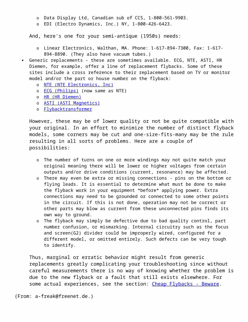
MAKE A HIGH VOLTAGE SUPPLY IN 5 MINUTESPrint PDF Favorite Facebook Twitter E-mail Flag
by Biotele
Step 2Some Info about Flyback Transformers
i
Flyback transformers come in all different shapes and sizes. Pick a big one.
The challenge with the flyback transformer is to find 3 pins out of 10 to 20 pins. One pin will be the high voltage ground the other two pins will be that of the primary coil that will connect to the CFL's electronic board.
If you can get the schematic of the flyback transformer that will save you time. However you can figure out the pins by following the instructions here .
Danger - if you are going to get the flyback from a TV or CRT you need to discharge it. It can hold a dangerous charge even days after the TV or CRT is turned off (see picture for details).
MAKE A HIGH VOLTAGE SUPPLY IN 5 MINUTESby Biotele
Step 3The Finished Setup
This is how the finished high voltage supply looks like.
Remember, this is a DC supply. The output from the thick wire is positive. In TVs and CRTs this high voltage output drives the negative electrons from the filament to the screen.
If you need AC high voltage, you have to remove the built-in diode or find an old flyback transformer that does not have a built-in diode.
« Previous Step
To Download the PDF or View All Steps, Become a Pro Member »
Next Step »
Step 4Troubleshooting

i
The first time I build the circuit, it worked immediately. I used a 26 watt CFL.
Then I decided to get a bigger CFL and I build it exactly like the first circuit. It didn't work. I was disappointed. I thought that the CFL electronics were shot.
But when I reconnected the fluorescent tube to the four wires, the CFL worked again. I realized that this type of CFL circuit needed to "sense" the filaments in order to operate. Remember, I was only using the outer wires and leaving the two inner wires alone.
So I put a resistor across the outer wire and the inner wire. The circuit worked! But within seconds the resistor was in flames.
So I decided to use a capacitor in place of resistor. The capacitor allows AC currents but blocks DC while a resistor allow both AC and DC currents to flow through it. Also a capacitor does not heat up because it provides a low resistance path for AC currents.
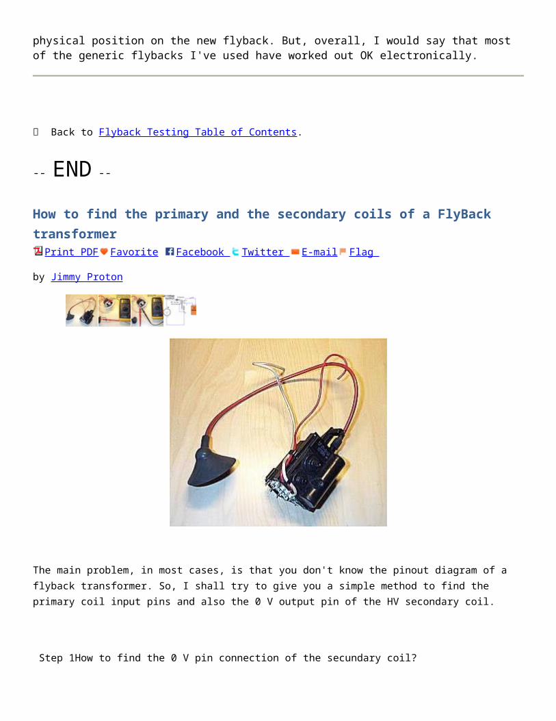
The capacitor worked great! The arcs produced were very big and thick.
So in summary there two things that can go wrong:
1. You wired it wrong, either on the CFL side or the flyback side. 2. The CFL electronics needs to sense the filament and you can use a capacitor as a substitute.
Use a high voltage rated capacitor. Mine was 400V and I got it from another CFL circuit.
While troubleshooting, be very careful, you are dealing with very high voltages and high currents.
When soldering, disconnect the circuit from the power outlet. « Previous Step
To Download the PDF or View All Steps, Become a Pro Member »
Next Step »
Step 5Disclaimer
i
The circuits in this Instructable use very high voltages and currents.
These currents and voltages are deadly! You can easily hurt yourself, as well. Build this circuit at your own risk.
This type of high frequency high voltage current is used in surgical cauterizers. So if you get shocked you will burn yourself and cut your flesh. There is also a considerable fire hazard from the circuit.
Use the Nikolai Tesla's safety techniques when working with high voltages:
1. Only use one hand (put your other hand on your lap or pocket) 2. Wear insulating shoes 3. Use a dead man stick or insulated pliers when touching or manipulating the circuit. 4. Use a power bar with a thermal fuse rather than sticking the circuit directly in the socket. This will limit the current that will go through your body.
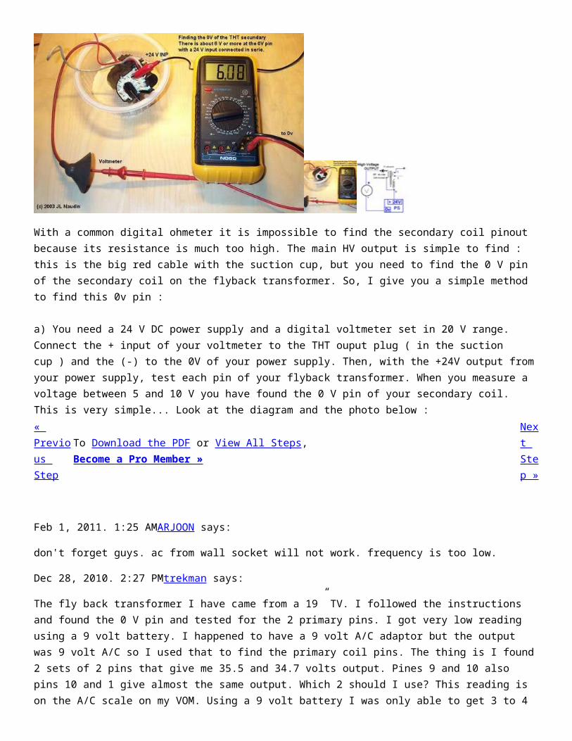
5. When soldering, disconnect the circuit from the power outlet.
Generally, in electricity it is the the current that kills. if the currents are low there is little danger even if the voltages are very high (think of Tesla holding the his Tesla coil).
This circuit has high currents which makes it considerably dangerous.
a 65W CFL can deliver 65mA easily (65W/1000v).
And if you look at the picture below, at greater than 50mA the little guy is dead.
« Previous Step
To Download the PDF or View All Steps, Become a Pro Member »
Next Step »
END
MINI TELSA COIL

On my last instructable about my mini Tesla Coil I did not do so well because I did not know much about them but since then I have learned much more and have batter plans.
How it works: First off the mains goes through a high voltage transformer and charges the capacitor bank. When the caps are done charging they will let the high voltage from the transformer "pass" through them. During that split second (much to fast for a human to detect) the arc will jump through the spark gap, which is automated with RSGTC's, the caps will discharge into the primary coil. This is where resonance comes in, the fast action of the caps and spark gap rapidly induces an electromagnetic field around the primary, what many dont know is it starts off as a low voltage that adds up each time the spark gap fires until it creates extra high voltage
-=This project deals with high voltage that could potentially be lethal, do not touch the streamers unless you know what your doing=-
-=never operate high voltage equipment before turning it off=-
-=I will be some information from my other instructable=-
Step 1You will need

i
1' tall 1/2" diameter PVC pipe or other non conductive cylinder about 5' of speaker wire, I didn't have enough of the thicker gauge wire8" tall 1" diameter PVC pipe, you can use something a little wider but I couldn't find anything10kV 23mA ignition transformer, you can get them on eBay for about $20-$4015 1kV 0.01uF film capacitorsabout 300ft of 32 awg mag wiresome 18 awg solid copper wire to connect everything2 round headed bolts or "i" screws, try to keep them as smooth as possible a 10"x4" piece of woodcopper connectors or some 1" bolts with nutsa drill with various sized bitsa hot glue guna soldering iron, with solder
« To Download the PDF or View All Steps, Next

Previous Step
Become a Pro Member »Step »
May 7, 2011. 7:43 PM.Unknown. says:
Do you still need RF chokes like the last tesla coil you did?(http://www.instructables.com/id/MINI-TESLA-COIL/step7/RF-chokes/)
May 7, 2011. 7:57 PM Jimmy Proton (author) says:
No, you don't even need them in the other one, its better without them.
Apr 29, 2011. 4:20 AMbamin1 says:
Hi. thank you for this instructable. if you want to know the equation you talked about in step 3, then download this program from this link
http://www.richardsplace.net/files/tccad20.zip
this program is called "Tesla Coil CAD" and its uses to designing tesla coils. Hope you like it. And I have a question. did you make it from the first time. I mean did it work from the first attempt??
Apr 30, 2011. 8:21 PM Jimmy Proton (author) says:
That program did not give an equation, just a calculator.
Apr 29, 2011. 4:30 PM Jimmy Proton (author) says:
Thanks, and yes it worked the first time I powered it up.
Apr 29, 2011. 1:07 PMIncandescence says:
Good job, this is one of the best instructables about Tesla coil I have seen.
I understand how the primary part work, but i don't get it for the secondary, an end of the coil has to be wired with the earth (something like a radiator?)?So the circuit is open, why is there a current and how can it produce an arc?
I'd like to build one but i'm a little concern about safety, I was really surprised when i saw you "touching" the arc, why doesn't that hurt you? I thought HV was dangerous.
Sorry if my english is not correct but it's not my mother tongue.

Apr 29, 2011. 4:44 PM Jimmy Proton (author) says:
Thanks!Grounding is usually only used for larger Tesla Coils like the one I'm working on now but this thing is so small it doesn't really matter. When the spark gap fires all the capacitor energy is released into the primary which makes a magnetic field that is picked up by the secondary. The primary induces more and more voltage each time it fires, it starts out low and builds up very high each time and if you know much about high voltage it tends to make sparks.There is very little output current so it wont hurt to touch it like that and you cant hardly feel it (you can a little bit) and if your not touching anything connected to ground or something else on the Tesla Coil then you'll be fine because it never leaves your body and even if you were it still probably wouldn't hurt you.
Step 2Spark gap
This is one of the most important part of the whole resonating thing, you could compare it to the heart in the brain, the brain cant control the hear without blood and the heart can't supply blood without the brain. with the heart being the spark gap and the brain being the capacitors: the capacitors charge up via the transformer, when they are charged the spark gap fires and releases its energy into the primary. without the spark gap you would have continuous input into the primary and without the capacitors all the power would just go straight through the spark gap. So lets make a spark gap.
If your using bolts:

Take two 2"x2" pieces of wood and drill a hole in the middle that can fit the bolts and put a nut on them to secure them or if the wood can hold them in place then dont worry about the nut. now glue these on the board in front of the inputs, the capacitors come after, then the primary, then the secondary.
If your using "i" screws:First drill 2 holes at an angle where ever your going to position your gap, now screw them into the hole and adjust them until the are at an appropriate length apart . « Previous Step
To Download the PDF or View All Steps, Become a Pro Member »
Next Step »
Step 3Capacitor bank
i
The amount of capacitance is determined by the input current, I'm not entirely sure how to calculate this but I would be grateful for anyone who could post a comment on what the equation is. Now it just so happens that the amount of capacitance we need is exactly the capacitance of the capacitors so we dont need to worry about soldering them in parallel, we just need to do something about the voltage so we only have to solder them in series. Its best to have the overall voltage of the capacitor bank about 2 or 3 times the about of voltage going in, so-we are using a 10kV 23mA transformer to power it, our capacitors are 1kV 10nF. Solder all the capacitors in series to increase the voltage to 15kV and were not going to solder any in parallel because like I said, the capacitance is perfect. You may want to put a 10M

ohm resistor across the leads to discharge the capacitors after use, you will also need to hot glue the capacitor lead to keep them from sparking over if you built yours like mine.
-=I did not get any pictures on how I made this because I built it for version 3 which I did not make an instructable on=-« Previous Step
To Download the PDF or View All Steps, Become a Pro Member »
Next Step »
Step 4The secondary and primary
i
secondary:This will take a lot of time do do but is pretty easy. All you have to do is wrap the 32 awg wire around the PVC pipe until there is about an inch of space left on each side and hold in place with tape or do what most people do and cover it in gloss. The way I did mine: I put 3 nails into my desk, on one I put the role of wire, the other two I used to keep tension on the wire so I could use both hands to hold the pipe, it took me about 1/2 an hour to finish.
primary:After you have cut your 1" diameter PVC to length grab your speaker wire and wrap it around he pipe. Strip the insulation off one end of the wire, and glue that to the bottom of the pipe. Put the other end in a vice and pull the wire tight (not to tight or the glue will come off), turn the pipe until you are all out of wire, the wire spacing should be about

1/2" apart. when you get to the end leave a bit of wire sticking out of the end and glue the insulated part to the pipe, now glue every turn to the pipe all the way down so it never comes loose.
Glue the secondary onto the end board, I drilled a 1" hole before i glued it on for support. now slide the primary over and glue it to the board after you have centered it.
In that last picture, the shine is the exposed wire but it looks like reflection on the insulation. « Previous Step
To Download the PDF or View All Steps, Become a Pro Member »
Nex
Step 5Wire it all up
Connect the HV transformer to the AC mains, connect the spark gap in parallel with the HV output, after that connect the capacitor bank series and close it off with the primary coil. Put the secondary coil inside the primary and hook the bottom wire to ground (I did nothing with it) and add a topload/toroid/torus to increase the voltage and effects of the sparks.
« Previous Step


![Catalogue FLYBACK Equivalent - [PDF Document] FLYBACK Equivalent FlyBack Equivalent flyback reemplazo conversor Flyback tv fly-back Flyback Tester Flyback Converter conversor Flyback](https://static.fdocuments.net/doc/165x107/5a832a447f8b9a9d308e9416/catalogue-flyback-equivalent-pdf-document-flyback-equivalent-flyback-equivalent.jpg)


