
ANNEX 30 RESOLUTION MSC.252(83) (adopted on 8 · PDF fileadoption of the revised performance...
48
MSC 83/28/Add.3 I:\MSC\83\28-Add-3.doc ANNEX 30 RESOLUTION MSC.252(83) (adopted on 8 October 2007) ADOPTION OF THE REVISED PERFORMANCE STANDARDS FOR INTEGRATED NAVIGATION SYSTEMS (INS) THE MARITIME SAFETY COMMITTEE, RECALLING Article 28(b) of the Convention on the International Maritime Organization concerning the functions of the Committee, RECALLING ALSO resolution A.886(21), by which the Assembly resolved that the function of adopting performance standards and technical specifications, as well as amendments thereto shall be performed by the Maritime Safety Committee and/or the Marine Environment Protection Committee, as appropriate, on behalf of the Organization, RECALLING FURTHER regulation V/15 of the International Convention for the Safety of Life at Sea (SOLAS), 1974, concerning principles relating to bridge design, design and arrangement of navigational systems and equipment and bridge procedures, NOTING that SOLAS regulation V/18 requires type approved navigational systems conforming to appropriate performance standards, RECOGNIZING the need to revise the performance standards for Integrated Navigation Systems (INS) to enhance the safety of navigation by providing integrated and augmented functions to avoid geographic, traffic and environmental hazards, HAVING CONSIDERED the recommendation on the revised performance standards for Integrated Navigation Systems made by the Sub-Committee on Safety of Navigation at its fifty-third session, and the Maritime Safety Committee at its eighty-third session, 1. ADOPTS the Revised Recommendation on performance standards for Integrated Navigation Systems (INS), set out in the Annex to the present resolution; 2. RECOMMENDS Governments ensure that Integrated Navigation Systems (INS): (a) if installed on or after 1 January 2011, conform to performance standards not inferior to those specified in the Annex to the present resolution; and (b) if installed on or after 1 January 2000 but before 1 January 2011, conform to performance standards not inferior to those specified in the Annex 3 to resolution MSC.86(70).
Transcript of ANNEX 30 RESOLUTION MSC.252(83) (adopted on 8 · PDF fileadoption of the revised performance...
MSC 83/28/Add.3
I:\MSC\83\28-Add-3.doc
ANNEX 30
RESOLUTION MSC.252(83)
(adopted on 8 October 2007)
ADOPTION OF THE REVISED PERFORMANCE STANDARDS FOR INTEGRATED NAVIGATION SYSTEMS (INS)
THE MARITIME SAFETY COMMITTEE, RECALLING Article 28(b) of the Convention on the International Maritime Organization concerning the functions of the Committee, RECALLING ALSO resolution A.886(21), by which the Assembly resolved that the function of adopting performance standards and technical specifications, as well as amendments thereto shall be performed by the Maritime Safety Committee and/or the Marine Environment Protection Committee, as appropriate, on behalf of the Organization, RECALLING FURTHER regulation V/15 of the International Convention for the Safety of Life at Sea (SOLAS), 1974, concerning principles relating to bridge design, design and arrangement of navigational systems and equipment and bridge procedures, NOTING that SOLAS regulation V/18 requires type approved navigational systems conforming to appropriate performance standards, RECOGNIZING the need to revise the performance standards for Integrated Navigation Systems (INS) to enhance the safety of navigation by providing integrated and augmented functions to avoid geographic, traffic and environmental hazards,
HAVING CONSIDERED the recommendation on the revised performance standards for Integrated Navigation Systems made by the Sub-Committee on Safety of Navigation at its fifty-third session, and the Maritime Safety Committee at its eighty-third session, 1. ADOPTS the Revised Recommendation on performance standards for Integrated Navigation Systems (INS), set out in the Annex to the present resolution; 2. RECOMMENDS Governments ensure that Integrated Navigation Systems (INS): (a) if installed on or after 1 January 2011, conform to performance standards not
inferior to those specified in the Annex to the present resolution; and (b) if installed on or after 1 January 2000 but before 1 January 2011, conform to
performance standards not inferior to those specified in the Annex 3 to resolution MSC.86(70).
MSC 83/28/Add.3 ANNEX 30 Page 2
I:\MSC\83\28-Add-3.doc
ANNEX
PERFORMANCE STANDARDS FOR INTEGRATED NAVIGATION SYSTEMS (INS)
1 Purpose of integrated navigation systems 1.1 The purpose of integrated navigation systems (INS) is to enhance the safety of navigation by providing integrated and augmented functions to avoid geographic, traffic and environmental hazards. 1.2 By combining and integrating functions and information the INS provides �added value� for the operator to plan, monitor and/or control safety of navigation and progress of the ship. 1.3 Integrity monitoring is an intrinsic function of the INS. The INS supports safety of navigation by evaluating inputs from several sources, combining them to provide information giving timely alerts of dangerous situations and system failures and degradation of integrity of this information. 1.4 The INS presents correct, timely, and unambiguous information to the users and provides subsystems and subsequent functions within the INS and other connected equipment with this information. 1.5 The INS supports mode and situation awareness. 1.6 The INS aims to ensure that, by taking human factors into consideration; the workload is kept within the capacity of the operator in order to enhance safe and expeditious navigation and to complement the mariner's capabilities, while at the same time to compensate for their limitations. 1.7 The INS aims to be demonstrably suitable for the user and the given task in a particular context of use. 1.8 The purpose of the alert management is specified in module C. 2 Scope 2.1 Navigational tasks 2.1.1 An INS comprises navigational tasks such as �Route planning�, �Route monitoring�, �Collision avoidance�, �Navigation control data�, �Navigation status and data display� and �Alert management�, including the respective sources, data and displays which are integrated into one navigation system. These tasks are described in paragraph 7. 2.1.2 An INS is defined as such if work stations provide multifunctional displays integrating at least the following navigational tasks/functions:
• �Route monitoring� • �Collision avoidance�
and may provide manual and/or automatic navigation control functions.

MSC 83/28/Add.3 ANNEX 30
Page 3
I:\MSC\83\28-Add-3.doc
2.1.3 Other mandatory tasks 2.1.3.1 An alert management is a part of the INS. The scope and the requirements of the alert management are specified in module C. 2.1.3.2 The presentation of navigation control data for manual control as specified in paragraph 7.5.2 of these performance standards is part of the INS. 2.1.4 Other navigational tasks/functions may also be integrated in the INS. 2.2 Task stations 2.2.1 The tasks are allocated to, and operated by the operator on, a defined set of multi-functional �task stations�. 2.2.2 The scope of an INS may differ dependent on the number and kind of tasks integrated. 2.2.3 Configuration, use, operation and display of the INS is situation-dependent on:
• shift underway, at anchor, and moored, • manual and automatic navigation control in different waters, • planned routine navigation and special manoeuvres.
3 Application of these performance standards 3.1 Purpose of these standards 3.1.1 The purpose of these performance standards is to support the proper and safe integration of navigational functions and information. 3.1.2 The purpose is in particular:
• to allow the installation and use of an INS instead of stand-alone navigational equipment onboard ships; and
• to promote safe procedures for the integration process; both for
• comprehensive integration; and • partial integration,
of navigational functions, data and equipment.
3.1.3 These standards supplement for INS functional requirements of the individual Performance Standards adopted by the Organization.
MSC 83/28/Add.3 ANNEX 30 Page 4
I:\MSC\83\28-Add-3.doc
3.2 Application to tasks 3.2.1 These performance standards are applicable to systems where functions/equipment of at least the navigational tasks mentioned in paragraph 2.1.2 are combined. 3.2.2 If further tasks are integrated, the requirements of these standards should apply to all additional functions implemented in the INS. 3.3 Modules of these standards 3.3.1 These performance standards are based on a modular concept which should provide for individual configurations and for extensions, if required. 3.3.2 These standards contain four modules:
• Module A for the requirements for the integration of navigational information, • Module B for the operational/functional requirements for INS based on a task-related
structure, • Module C for the requirements of the Alert management, and • Module D for the Documentation requirements.
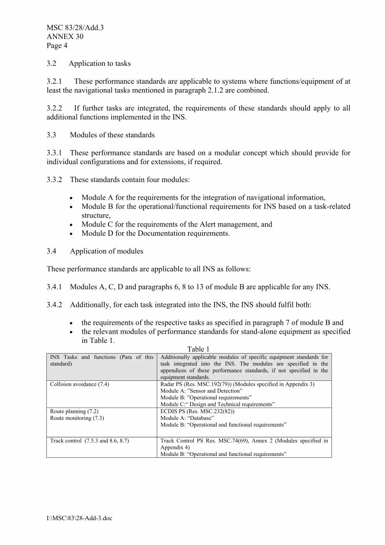
3.4 Application of modules These performance standards are applicable to all INS as follows: 3.4.1 Modules A, C, D and paragraphs 6, 8 to 13 of module B are applicable for any INS. 3.4.2 Additionally, for each task integrated into the INS, the INS should fulfil both:
• the requirements of the respective tasks as specified in paragraph 7 of module B and • the relevant modules of performance standards for stand-alone equipment as specified
in Table 1. Table 1
INS Tasks and functions (Para of this standard)
Additionally applicable modules of specific equipment standards for task integrated into the INS. The modules are specified in the appendices of these performance standards, if not specified in the equipment standards.
Collision avoidance (7.4)
Radar PS (Res. MSC.192(79)) (Modules specified in Appendix 3) Module A: �Sensor and Detection� Module B: �Operational requirements� Module C:� Design and Technical requirements�
Route planning (7.2) Route monitoring (7.3)
ECDIS PS (Res. MSC.232(82)) Module A: �Database� Module B: �Operational and functional requirements�
Track control (7.5.3 and 8.6, 8.7) Track Control PS Res. MSC.74(69), Annex 2 (Modules specified in Appendix 4) Module B: �Operational and functional requirements�
MSC 83/28/Add.3 ANNEX 30
Page 5
I:\MSC\83\28-Add-3.doc
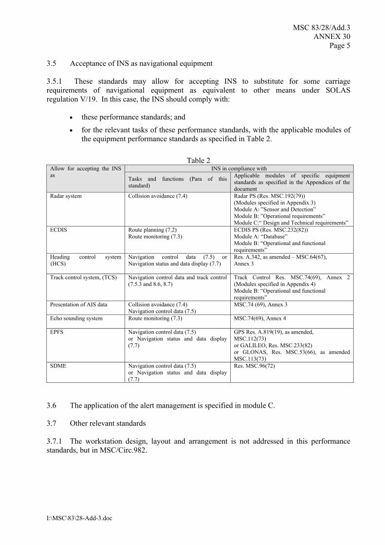
3.5 Acceptance of INS as navigational equipment 3.5.1 These standards may allow for accepting INS to substitute for some carriage requirements of navigational equipment as equivalent to other means under SOLAS regulation V/19. In this case, the INS should comply with:
• these performance standards; and
• for the relevant tasks of these performance standards, with the applicable modules of the equipment performance standards as specified in Table 2.
Table 2
INS in compliance with Allow for accepting the INS as Tasks and functions (Para of this
standard)
Applicable modules of specific equipment standards as specified in the Appendices of the document
Radar system
Collision avoidance (7.4)
Radar PS (Res. MSC.192(79)) (Modules specified in Appendix 3) Module A: �Sensor and Detection� Module B: �Operational requirements� Module C:� Design and Technical requirements�
ECDIS Route planning (7.2) Route monitoring (7.3)
ECDIS PS (Res. MSC.232(82)) Module A: �Database� Module B: �Operational and functional requirements�
Heading control system (HCS)
Navigation control data (7.5) or Navigation status and data display (7.7)
Res. A.342, as amended � MSC.64(67), Annex 3
Track control system, (TCS) Navigation control data and track control (7.5.3 and 8.6, 8.7)
Track Control Res. MSC.74(69), Annex 2 (Modules specified in Appendix 4) Module B: �Operational and functional requirements�
Presentation of AIS data Collision avoidance (7.4) Navigation control data (7.5)
MSC.74 (69), Annex 3
Echo sounding system Route monitoring (7.3)
MSC.74(69), Annex 4
EPFS Navigation control data (7.5) or Navigation status and data display (7.7)
GPS Res. A.819(19), as amended, MSC.112(73) or GALILEO, Res. MSC.233(82) or GLONAS, Res. MSC.53(66), as amended MSC.113(73)
SDME Navigation control data (7.5) or Navigation status and data display (7.7)
Res. MSC.96(72)
3.6 The application of the alert management is specified in module C. 3.7 Other relevant standards 3.7.1 The workstation design, layout and arrangement is not addressed in this performance standards, but in MSC/Circ.982.
MSC 83/28/Add.3 ANNEX 30 Page 6
I:\MSC\83\28-Add-3.doc
4 Definitions For the purpose of these standards the definitions in Appendix 1 apply. Module A � Integration of Information 5 Requirements for integration of navigational information 5.1 Interfacing and data exchange 5.1.1 An INS should combine, process and evaluate data from connected sensors and sources. 5.1.2 The availability, validity and integrity of data exchange within the INS and from connected sensors and sources should be monitored. 5.1.3 A failure of data exchange should not affect any independent functionality. 5.1.4 Interfacing to, from, and within the INS should comply with international standards for data exchange and interfacing as appropriate. 5.1.5 The interface(s) should comply with the interface requirements of the alert management as described in Module C of these performance standards. 5.2 Accuracy 5.2.1 INS data should comply with the accuracy and resolution required by applicable performance standards of the Organization. 5.3 Validity, plausibility, latency 5.3.1 Validity 5.3.1.1 Data failing validity checks should not be used by the INS for functions dependent on these data, unless for cases where the relevant performance standards specifically allow use of invalid data. There should be no side effects for functions not depending on this data. 5.3.1.2 When data used by the INS for a function becomes invalid, or unavailable, a warning should be given. When data not actually in use by the INS becomes invalid, or unavailable, a this should be indicated at least as a caution. 5.3.2 Plausibility 5.3.2.1 Received or derived data that is used or distributed by the INS should be checked for plausible magnitudes of values. 5.3.2.2 Data which has failed the plausibility checks should not be used by the INS and should not affect functions not dependent on these data.
MSC 83/28/Add.3 ANNEX 30
Page 7
I:\MSC\83\28-Add-3.doc
5.3.3 Latency 5.3.3.1 Data latency (timeliness and repetition rate of data) within the INS should not degrade the functionality specified in the relevant performance standards. 5.4 Consistent common reference system (CCRS) 5.4.1 Consistency of data 5.4.1.1 The INS should ensure that the different types of information are distributed to the relevant parts of the system, applying a �consistent common reference system� for all types of information. 5.4.1.2 Details of the source and the method of processing of such data should be provided for further use within INS. 5.4.1.3 The CCRS should ensure that all parts of the INS are provided with the same type of data from the same source. 5.4.2 Consistent common reference point 5.4.2.1 The INS should use a single consistent common reference point for all spatially related information. For consistency of measured ranges and bearings, the recommended reference location should be the conning position. Alternative reference locations may be used where clearly indicated or distinctively obvious. The selection of an alternative reference point should not affect the integrity monitoring process. 5.4.3 Consistency of thresholds 5.4.3.1 The INS should support the consistency of thresholds for monitoring and alert functions. 5.4.3.2 The INS should ensure by automatic means that consistent thresholds are used by different parts of an INS, where practicable. 5.4.3.3 A caution may be given when thresholds entered by the bridge team differ from thresholds set in other parts of the INS. 5.5 Integrity monitoring 5.5.1 The integrity of data should be monitored and verified automatically before being used, or displayed. 5.5.2 The integrity of information should be verified by comparison of the data derived independently from at least two sensors and/or sources, if available. 5.5.3 The INS should provide manual or automatic means to select the most accurate method of integrity monitoring from the available sensors and/or sources.

MSC 83/28/Add.3 ANNEX 30 Page 8
I:\MSC\83\28-Add-3.doc
5.5.4 A clear indication of the sensors and sources of data selected for integrity monitoring should be provided. 5.5.5 The INS should provide a warning, if integrity verification is not possible or failed. 5.5.6 Data which fails the integrity monitoring function or data where integrity monitoring is not possible should not be used for automatic control systems/functions. 5.6 Marking of data 5.6.1 The data should be marked with the source and the results of validity, plausibility checks and integrity monitoring to enable subsequent functions to decide whether their input data complies with their requirements or not. 5.7 Selection of sensors and sources 5.7.1 INS should provide two user selectable sensor/source selection modes when multiple sensors/sources are available; manual sensor/source selection mode and automatic sensor/source selection mode. 5.7.2 In manual sensor/source selection mode it should be possible to select individual sensors/ sources for use in the INS. In case a more suitable sensor/source is available this should be indicated. 5.7.3 In automatic sensor/source selection mode, the most suitable sensors/sources available should be automatically selected for use in the INS. It should further be possible to manually exclude individual sensors/sources from being automatically selected. Module B � Task related requirements for Integrated Navigation Systems 6 Operational requirements 6.1 The design of the INS should ease the workload of the bridge team and pilot in safely and effectively carrying out the navigation functions incorporated therein. 6.2 The integration should provide all functions, depending of the task for which the INS is used and configured, to facilitate the tasks to be performed by the bridge team and pilot in safely navigating the ship. 6.3 Each part of the INS should comply with all applicable requirements adopted by the Organization, including the requirements of these performance standards. 6.4 When functions of equipment connected to the INS provide facilities in addition to these performance standards, the operation and, as far as is reasonably practicable, the malfunction of such additional facilities should not degrade the performance of the INS below the requirements of these standards. 6.5 The integration of functions of individual equipment into the INS should not degrade the performance below the requirements specified for the individual equipment by the Organization.
MSC 83/28/Add.3 ANNEX 30
Page 9
I:\MSC\83\28-Add-3.doc
6.6 Alerts should be generated and presented according to Module C. 7 Task and functional requirements for an INS 7.1 General 7.1.1 The configuration of the INS should be modular and task - oriented. The navigational tasks of an INS are classified as �Route planning�, �Route monitoring�, �Collision avoidance�, �Navigation control data�, �Status and data display� and �Alert management�. Each of these tasks comprises the respective functions and data. 7.1.2 All tasks of an INS should use the same electronic chart data and other navigational databases such as routes, maps, tide information. 7.1.3 If Electronic Navigational Charts (ENCs) are available, they should be used as common data source for INS. 7.1.4 Paragraphs 7.2 to 7.5 and 7.7 apply, if the respective task is integrated into the INS. 7.2 Task �Route planning� 7.2.1 ECDIS performance standards related mandatory functions and data The INS should provide the route planning functions and data as specified in Module A and B of the revised ECDIS performance standards (resolution MSC.232(82)). 7.2.2 Procedures for voyage planning The INS should be capable of supporting procedures for relevant parts of voyage planning, as adopted by the Organization1. 7.2.3 Additional mandatory functions The INS should provide means for
• administering the route plan (store and load, import, export, documentation, protection),
• having the route check against hazards based on the planned minimum under keel clearance as specified by the mariner,
• checking of the route plan against manoeuvring limitation, if available in the INS, based on parameters turning radius, rate of turn (ROT), wheel-over and course changing points, speed, time, ETAs,
• drafting and refining the route plan against meteorological information if available in the INS.
1 Resolution A.893(21) on Guidelines for voyage planning.

MSC 83/28/Add.3 ANNEX 30 Page 10
I:\MSC\83\28-Add-3.doc
7.3 Task �Route monitoring� 7.3.1 ECDIS performance standards related mandatory functions and data The INS should provide the route monitoring functions and data as specified in Module A and B in the ECDIS performance standards. 7.3.2 Additional mandatory functions The INS should provide capability for
• optionally overlaying radar video data on the chart to indicate navigational objects, restraints and hazards to own ship in order to allow position monitoring evaluation and object identification,
• determination of deviations between set values and actual values for measured under-keel clearance and initiating an under-keel clearance alarm, if fitted,
• the alphanumeric display the present values of Latitude, Longitude, heading, COG, SOG, STW, under-keel clearance, ROT (measured or derived from change of heading),
• AIS reports of AtoNs, and if track control is integrated into the INS,
• it should be possible to include the planned track and to provide, monitor and display the track related and manoeuvring data.
7.3.3 Optional Functions For navigational purposes, the display of other route-related information on the chart display is permitted, e.g.,
• tracked radar targets and AIS targets • AIS binary and safety-related messages • initiation and monitoring of man-over-board and SAR manoeuvres (search and rescue
and man-over-board modes) • NAVTEX • tidal and current data • weather data • ice data.
7.3.4 Search and rescue mode 7.3.4.1 If available it should be possible to select on the route monitoring display a predefined display mode for a �search and rescue� situation, that can be accessed upon simple operator command. 7.3.4.2 In the search and rescue mode a superimposed graphical presentation of the datum (geographic point, line, or area used as a reference in search planning), initial most probable area for search, commence search point and search pattern chosen by the operator (expanding square search pattern, sector search pattern or parallel track search pattern) with track spacing defined by him should be presented.
MSC 83/28/Add.3 ANNEX 30
Page 11
I:\MSC\83\28-Add-3.doc
7.3.5 Man-over-board (MOB) mode 7.3.5.1 If available it should be possible to select on the route monitoring display a predefined display mode for a �man-over-board� situation, that can be accessed upon simple operator command. 7.3.5.2 In the man-over-board mode a superimposed graphical presentation of a operator selectable man-over-board manoeuvre should be presented. 7.3.5.3 The man-over-board position should be memorised by a simple operator action. 7.3.5.4 An urgency manoeuvring procedure should be available at the display taking set and drift into consideration. 7.4 Task �Collision Avoidance� 7.4.1 Radar performance standards related mandatory functions and data The INS should provide the collision avoidance functions and data as specified in Module A and B of the Radar performance standards. 7.4.2 Additional mandatory functions 7.4.2.1 It should be possible to present less information of ENC database objects than specified in MSC.232(82) for display base. 7.4.2.2 Target association and target data integration If target information from multiple sensors/sources (radar and AIS; 2 radar sensors) are provided on one task station:
• the possibility of target association should be provided for mutual monitoring and to avoid the presentation of more than one symbol for the same target,
• the association of AIS and radar targets should follow the requirements of resolutions MSC.192(79) and MSC.191(79),
• common criteria should be used for raising target related alerts, e.g., CPA/TCPA. 7.4.2.3 Target identifier For identical targets unique and identical target identifiers should be used for presentation on all INS displays. Where a target from more than one source can be presented on one display the identifier should be amended as required. Amended target identifiers should be used for all INS display presentations.

MSC 83/28/Add.3 ANNEX 30 Page 12
I:\MSC\83\28-Add-3.doc
7.4.2.4 Combined radar signals A display may present combined radar signals from more than one radar source. The malfunctions of this additional facility should not degrade the presentation of the radar source selected as primary. The primary and the other source(s) should be indicated as such. 7.4.3 Optional functions Optionally, the following information may be displayed:
• true scaled ship symbols and CPA/TCPA and bow crossing range (BCR) / bow crossing time (BCT) related to the real dimensions
• chart data from the common database of INS: traffic-related object layers. 7.5 Task �Navigation Control Data� 7.5.1 General To support the manual and automatic control of the ship�s primary movement the INS navigation control task should provide the following functionality:
• display of data for the manual control of the ship�s primary movement • display of data for the automatic control of the ship�s primary movement • presentation and handling of external safety related messages.
7.5.2 Presentation of navigation control data for manual control 7.5.2.1 For manual control of the ship�s primary movement the INS navigation control display should allow at least to display the following information:
• under keel clearance (UKC) and UKC profile • STW, SOG, COG • position • heading, ROT (measured or derived from change of heading) • rudder angle • propulsion data • set and drift, wind direction and speed (true and/or relative selectable by the operator),
if available • the active mode of steering or speed control • time and distance to wheel-over or to the next waypoint • safety related messages e.g., AIS safety-related and binary messages, Navtex.
7.5.3 Presentation of navigation control data for automatic control 7.5.3.1 For automatic control of the ship�s primary movement, the INS navigation control display should allow at least and as default the display of the following information:
• all information listed for manual control • set and actual radius or rate of turn to the next segment.
MSC 83/28/Add.3 ANNEX 30
Page 13
I:\MSC\83\28-Add-3.doc
7.5.4 The navigation control data should be presented:
• in digital and where appropriate in analogue form, e.g., mimic elements, logically arranged on and around a symbolic outline of a ship,
• if applicable, together with their �set- values�, • if applicable and on demand together with a history presentation to indicate the
trend of the parameter. 7.6 Task �Alert management� 7.6.1 Scope, operational requirements and alert-related requirements are specified in Module C of these performance standards. 7.7 Task �Status and data display� 7.7.1 Mandatory data display functions The INS should provide the following data display functions:
• presentation of mode and status information • presentation of the ship�s static, dynamic and voyage-related AIS data • presentation of the ship�s available relevant measured motion data together with
their �set � values� • presentation of received safety related messages, such as AIS safety-related and
binary messages, Navtex • presentation of INS configuration • presentation of sensor and source information.
7.7.2 Mandatory data management functions The INS should provide the following management functions:
• setting of relevant parameters • editing AIS own ship�s data and information to be transmitted by AIS messages.
7.7.3 Optional data display functions The INS may provide on demand:
• tidal and current data • weather data, ice data • additional data of the tasks Navigation control and Route monitoring and AIS target
data.
MSC 83/28/Add.3 ANNEX 30 Page 14
I:\MSC\83\28-Add-3.doc
8 Functional requirements for INS task stations 8.1 Number of task stations 8.1.1 The number of task stations on the bridge depends on the tasks integrated into the INS. It should support the simultaneous operation and presentation of at least the minimum set of tasks necessary to meet the carriage requirements of SOLAS regulation V/19. 8.1.2 To specify the required number of task stations the required backup arrangements as mandated by the carriage requirements of SOLAS regulation V/19 should be taken into account. 8.2 For each tasks of:
• route monitoring • collision avoidance • navigation control data,
a task station should be provided, if the respective task is part of the INS. 8.3 Additional tasks For the tasks of:
• route planning, • status and data display, and • alert management,
means should be provided to operate the tasks at least at one of the task stations referred to on paragraph 8.2 or at least at another additional task station at the choice of the bridge team and pilot. 8.4 Remote route planning For the task �Route planning�, a separate remote task station may be provided. 8.5 The allocation of the tasks to the task stations should be sufficiently flexible, to support all navigational situations, and should be sufficiently simple to support team working and awareness of operator roles. The selection of the task at the task station should be possible by a simple operator action. 8.6 Track control If the function of track control is implemented in the INS, 8.6.1 it should be possible to display the planned route graphically on the task stations for:
• �Route monitoring�, and/or • �Collision avoidance�.
MSC 83/28/Add.3 ANNEX 30
Page 15
I:\MSC\83\28-Add-3.doc
8.6.2 the control and operation of this function by the user should be possible via the task stations for:
• �Route monitoring�, and/or • �Collision avoidance�.
8.7 Automatic control functions 8.7.1 Task station with control Only one, clearly indicated task station should be in control of an automatic function and only one task station should at any time be assigned to accept control commands. It should clearly be indicated to the bridge team and pilot, if not otherwise obvious, which task station is in control of these functions. 8.7.2 It should be possible to take over the control from a task station. In this case the set control values and limits should remain unchanged. 8.7.3 The information relevant for the selected control function should be available for continuous display, at least upon a single operator command, and should in be presented when an automatic control function is activated or changed. 8.7.4 Override 8.7.4.1 It should be allowed by a single operator action to override or by-pass any automated function, regardless of the operational mode and the failure status of the INS. 8.7.4.2 The INS should resume automatic functions only after an appropriate message and intentional operator action, considering all necessary starting conditions. 9 Functional requirements for displays of INS 9.1 General 9.1.1 The INS should comply with the presentation requirements adopted by the Organization2. 9.1.2 All essential information should be displayed clearly and continuously. Additional navigational information may be displayed, but should not mask, obscure or degrade essential information required for the display by its primary task, as specified in this performance standards. 9.1.3 The INS should be capable of displaying data available from the sensors. 9.1.4 The information should be displayed together with the indication of its source (sensor data, result of calculation or manual input), unit of measurement and status, including mode. 9.1.5 Display and update of essential information available in the equipment as well as safety related automatic functions should not be inhibited due to operation of the equipment. 2 MSC.191(79), SN/Circ.243.
MSC 83/28/Add.3 ANNEX 30 Page 16
I:\MSC\83\28-Add-3.doc
9.2 Default display configurations and operational modes 9.2.1 The INS should offer default display configurations for the tasks route monitoring and collision avoidance selectable at each task station to provide the bridge team and pilot with a standardized display. This configuration should be accessible by a simple operator action. The basic requirements for these display configurations are specified in Appendix 6. 9.2.2 The INS should provide operational modes for open sea, coastal, confined waters (pilotage, harbour berthing, anchorage). 9.2.3 User-defined display modes It is recommended that the INS provides means to generate pre-defined or operator-defined display modes, that are optimally suitable to the navigation task. 9.2.4 When switching the task from one task station to another, the current display configuration should be maintained. 9.3 Mode and status awareness 9.3.1 The operational mode in use should be clearly indicated to the bridge team and pilot. 9.3.2 If the mode in use is not the normal mode, to fully perform the functions required for the INS, this should be clearly indicated. Example of modes other than the normal mode are:
• degraded condition modes, in which the INS cannot fully perform all functions • �service modes� • simulation mode • training (familiarization) mode • other modes, in which the INS cannot be used for navigation.
9.3.3 If the system is in a degraded condition this should be sufficiently clear that the bridge team and pilot can understand the nature of the failure and its consequences. 9.3.4 The INS should indicate the operational status of automated functions and integrated components, systems and/or subsystems. 9.4 Information display 9.4.1 It should be possible to display the complete system configuration, the available configuration and the configuration in use. 9.4.2 The INS should provide the means to display the type of data, source and availability. 9.4.3 The INS should provide the means to display the type of function and availability.
MSC 83/28/Add.3 ANNEX 30
Page 17
I:\MSC\83\28-Add-3.doc
9.4.4 The INS should provide the means to display the device identification and its availability. 9.4.5 Ships and system related parameters and settings should be displayed on demand. 10 Human Machine Interface 10.1 General 10.1.1 For the design and layout of human machine interface (HMI) of the INS, MSC/Circ.982 and relevant guidance on application of SOLAS regulation V/15 adopted by the Organization should be taken into account. 10.1.2 Integrated graphical and alphanumeric display and control functions should adopt a consistent human machine interface (HMI) philosophy and implementation. 10.1.3 The design and implementation of the INS should ensure that it is simple to operate by a trained user. 10.2 System Design 10.2.1 The design of the system should facilitate the tasks to be performed by the bridge team and pilot in navigating the ship safely under all operational conditions. 10.2.2 The configuration of the equipment and presentation of information at workstations should permit observation or monitoring by the bridge team and pilot under all operating conditions. 10.2.3 The design of the system should avoid the potential single point failure by one person during operation, and should minimize the risk of human error. 10.2.4 The operation of the system should be designed to avoid distraction from the task of safe navigation. 10.3 Display 10.3.1 Information should be presented consistently within and between different sub-systems. Standardized information presentation, symbols and coding should be used according to resolution MSC.191(79). 10.4 Input 10.4.1 The INS should be so designed that the requested manual inputs are consistent throughout the system and can be easily executed. 10.4.2 The INS should be designed that the basic functions can be easily operated. 10.4.3 Complex or error-prone interaction with the system should be avoided.
MSC 83/28/Add.3 ANNEX 30 Page 18
I:\MSC\83\28-Add-3.doc
10.4.4 For manual inputs that may cause unintended results, the INS should request confirmation before acceptance, thus providing a plausibility check. 10.4.5 Checks in the dialogue and in the input handling should be provided to prevent erroneous data or control inputs. 10.4.6 Wherever possible, an �undo� function should be provided. 11 INS Back-up requirements and redundancies 11.1 General 11.1.1 Adequate back-up arrangements should be provided to ensure safe navigation in case of a failure within the INS. 11.1.1.1 In case of failure of one part or function of the INS, including network failures, it should be possible to operate each other individual part or function separately; at least the requirements specified for individual equipment adopted by the Organization should be met, as far as applicable. 11.1.1.2 The back-up arrangement should enable a safe take-over of the INS functions and ensure that an INS failure does not result in a critical situation. 11.1.2 The failure of a single task station should not result in the loss of a function mandated by the carriage requirements of SOLAS. 11.1.3 In case of a breakdown of one task station, at least one task station should be able to take over the tasks. 11.1.4 The failure or loss of one hardware component of the INS should not result in the loss of any one of the INS tasks:
• Route planning • Route monitoring • Collision avoidance • Navigation control data • Status and data display • Alert management.
Where track control is an INS function, this would not require the duplication of heading control or autopilot. 11.1.5 The INS should allow that the back-up component automatically (if possible) takes over the operation of the primary component.

MSC 83/28/Add.3 ANNEX 30
Page 19
I:\MSC\83\28-Add-3.doc
11.2 Hardware Redundancies 11.2.1 Required navigational sensor/source back-up For the following sensors/sources of an INS, an approved back-up should be available for the INS:
• electronic position fixing • heading measurement • speed measurement • radar • chart database.
12 System failures and fallback arrangement 12.1 The INS should, after a failure, and when the back-up activation is not successful support the availability of essential information and functions through the use of appropriate fallback arrangements (see 12.7). 12.2 Restored operation Normal operation, after use of a fallback arrangement, should only be restored upon confirmation by the operator. 12.3 Failure or change of sensor 12.3.1 The failure or change of a sensor should not result in sudden changes of control commands or loss of manoeuvring control. This may be accomplished by appropriate integrity checks using the information from several sources. 12.3.2 In case of a sensor or source failure, the system should provide an alert and indicate (an) alternative sensor(s) or source(s), as available. 12.3.3 If sensors or sources are not able to provide necessary ship status or navigation data for automatic control functions, a dead reckoning procedure should provide the missing information, as far as practicable. 12.4 Storage of system related parameters All system related parameters and settings should be stored in a protected way for reconfiguration of the INS. 12.5 The automatic response to malfunctions should result in the safest possible configuration accompanied by an alert. 12.6 Alert management 12.6.1 System failures should be alerted according to the requirements described in Module C. 12.6.2 Loss of system communication between the alert management and the navigational systems and sensors should be indicated as a warning at the central alert management HMI.

MSC 83/28/Add.3 ANNEX 30 Page 20
I:\MSC\83\28-Add-3.doc
12.6.3 A system failure of the alert management or the loss of system communication between the alert management and the navigational functions, sources and/or sensors, should not lead to the loss of the alert announcement functionality of the individual navigational functions, sources/sensors. 12.7 Fallback for navigational information failure 12.7.1 In the event of failures of navigational information and to maintain minimum basic operation,
• there should be a permanent indication of the failed input information and the fall-back activated,
• the respective actions of the alert management should be activated, and • the fallback arrangements listed below should be provided.
12.7.2 Route monitoring 12.7.2.1 Failure of heading information (Azimuth Stabilization) The INS should display own ship�s position and over-ground-motion vector in the chart and not the ship�s heading line. 12.7.2.2 Failure of course and speed over ground information The INS should display own ship�s position and heading line. 12.7.3 Collision avoidance In the case of failure of:
• Heading information • Speed through the water information • Course and speed over ground information • Position input information • Radar video input information • AIS input information,
the INS should operate as defined in the operational Module B4 of the proposed modular structure for radar performance standards as set out in appendix 3. 12.7.4 Heading/Track control The requirements for the applicable control function as specified in the individual performance standards should apply.
MSC 83/28/Add.3 ANNEX 30
Page 21
I:\MSC\83\28-Add-3.doc
13 Technical requirements 13.1 General 13.1.1 In addition to meeting the relevant requirements of resolution A.694(17)∗, the INS should comply with the requirements of these performance standards. 13.1.2 Means should be provided to monitor and to display hardware malfunctions of the INS. Alerts should be provided in case of malfunctions. 13.2 Requirements for hardware and/or processors 13.2.1 Sensor 13.2.1.1 A sensor or part thereof is not part of the INS, if it only supplies raw data. 13.2.1.2 Processing of raw data from sensors may be part of the INS. 13.2.1.3 In case sources perform functions of the INS these functions and interfaces should conform with the relevant parts of these performance standards. 13.2.2 Actuator and controller An actuator, controller or part thereof is not part of the INS, if it only receives data or commands and does not perform other functions of the INS as required by these standard. 13.3 Requirements for software 13.3.1 The operational software should fulfil the requirements of the relevant international standards related to maritime navigation and communication equipment. 13.4 Requirements for power supply 13.4.1 Power supply requirements applying to parts of the INS as a result of other IMO requirements should remain applicable. 13.4.2 The INS including the sensors for position, speed, heading and depth should be supplied:
.1 from both the main and the emergency source of electrical power with automated
changeover through a local distribution board with provision to preclude inadvertent shutdown; and
.2 from a transitional source of electrical power for a duration of not less than 45 s.
∗ Refer to publication IEC 60945.

MSC 83/28/Add.3 ANNEX 30 Page 22
I:\MSC\83\28-Add-3.doc
13.5 Power interruptions and shutdown 13.5.1 After a power interruption full functionality of the INS should be available after recovery of all subsystems. The INS should not increase the recovery time of individual subsystem functions after power restoration. 13.5.2 If subjected to a power interruption the INS should, upon restoration of power, maintain the configuration in use and continue automated operation, as far as practicable. Automatic control functions should only be restored upon confirmation by the operator. 13.6 Communication protocols 13.6.1 Standardized and approved communication protocols for interfaces should be used where possible∗. 13.7 Installation 13.7.1 The INS should be installed so that it can meet the requirements of the relevant International Standards. 13.7.2 The INS should be installed taking into account the guidelines in MSC/Circ.982 and relevant guidance on application of SOLAS regulation V/15, adopted by the Organization. Module C � Alert management 14 Purpose 14.1 The purpose of the alert management is to enhance the handling, distribution and presentation of alerts within an INS. 15 Scope 15.1 To enhance the safety of navigation these performance standards provide requirements for the treatment of alerts within an INS and its associated individual operational/ functional-modules and sensor/source-modules. 15.2 The alert management harmonizes the priority, classification, handling, distribution and presentation of alerts, to enable the bridge team to devote full attention to the safe navigation of the ship and to immediately identify any abnormal situation requiring action to maintain the safe navigation of the ship. 15.3 These performance standards specify a central alert management HMI to support the bridge team in the immediate identification of any abnormal situation, of the source and reason for the abnormal situation and support the bridge team in its decisions for the necessary actions to be taken.
∗ Refer to publication IEC 61162.
MSC 83/28/Add.3 ANNEX 30
Page 23
I:\MSC\83\28-Add-3.doc
15.4 The alert management architecture and the acknowledgement concept specified, avoid unnecessary distraction of the bridge team by redundant and superfluous audible and visual alarm announcements and reduces the cognitive load on the operator by minimizing the information presented to which is necessary to assess the situation. 15.5 The alert management should support the proper application of SOLAS regulation V/15. 15.6 The architecture of the module of the performance standards is kept extendable to allow to include further alerts on the bridge and the development of performance standards for a bridge alert management. 16 Application 16.1 These performance standards are applicable to any navigational aid within an INS and its associated individual operational/functional-modules and sensor/source-modules. 16.2 In addition to meeting the requirements of these performance standards the INS alert management should comply with the relevant requirements of the Organization3. 16.3 The general principles of these standards as described in paragraphs 19 and 20 of these performance standards should apply to all alerts presented on the bridge, as far as practicable. 17 Definitions For the purpose of these standards the definitions in Appendix 1 apply. 18 General requirements 18.1 The alert management should provide:
• the means used to draw the attention of the bridge team to the existence of abnormal situations,
• the means to enable the bridge team to identify and address that condition, • the means for the bridge team and pilot to assess the urgency of different abnormal
situations in cases where more than one abnormal situation has to be handled, • the means to enable the bridge team to handle alert announcements, and • the means to manage all alert related states in a distributed system structure in
consistent manner. 18.2 If practicable, there should be not more than one alert for one situation that requires attention. 18.3 The alert management should as a minimum be able to handle all alerts required by performance standards adopted by the Organization for navigational equipment comprised by the INS or connected to the INS. The alert management should have the capability to handle all other alerts of navigational equipment comprised by the INS or connected to the INS in identical manner and should incorporate all alerts that are critical to the safety of navigation.
3 MSC.128(75), MSC.191(79).

MSC 83/28/Add.3 ANNEX 30 Page 24
I:\MSC\83\28-Add-3.doc
18.4 The logical architecture of the alert management and the handling concept for alerts should provide the capability to minimize the number of alerts especially those on a high priority level (e.g. using system knowledge from redundancy concepts inside INS and evaluating inherent necessities for alerts against navigational situations, operational modes or activated navigational functions). 18.5 It should be possible to provide the central alert management HMI at least on the navigating and manoeuvring workstation and allowing the handling by the bridge team. 18.6 The audible announcement of alerts should enhance the guidance of the bridge team to the task stations or displays which are directly assigned to the function generating the alert and presenting the cause of the announcement and related information for decision support, e.g., dangerous target alarms should appear and have to be acknowledged at the workstation where the collision avoidance function is provided. 18.7 As alerts can be displayed at several locations, the system should be consistent as far as practicable with respect to how alerts are displayed, silenced and acknowledged at any one task station of the INS. 19 Priorities and categories 19.1 Priorities of alerts 19.1.1 The alert management should distinguish between the three priorities listed:
• Alarms • Warnings and • Cautions
19.1.2 Alarms should indicate conditions requiring immediate attention and action by the bridge team. 19.1.3 Warnings should indicate changed conditions and should be presented for precautionary reasons which are not immediately hazardous but which may become so, if no action is taken. 19.1.4 Cautions should indicate a condition which does not warrant an alarm or warning condition, but still requires attention and out of the ordinary consideration of the situation or of given information. 19.1.5 Alerts additional to the alerts required by the organization should be assigned to an priority level using the criteria for classification. 19.2 Criteria for classification of alerts 19.2.1 Criteria for classification of alarms:
• conditions requiring immediate attention and action by the bridge team to avoid any kind of hazardous situation and to maintain the safe navigation of the ship
• or escalation required as alarm from a not acknowledged warning.
MSC 83/28/Add.3 ANNEX 30
Page 25
I:\MSC\83\28-Add-3.doc
19.2.2 Criteria for classification of warnings:
• Conditions or situations which require immediate attention for precautionary reasons, to make the bridge team aware of conditions which are not immediately hazardous, but may become so.
19.2.3 Criteria for classification of cautions:
• awareness of a condition which still requires attention out of the ordinary consideration of the situation or of given information.
19.3 Categories of alerts 19.3.1 Alerts should be separated for the alert handling in INS into two categories of alerts: 19.3.1.1 Category A alerts Category A alerts are specified as alerts where graphical e.g. radar, ECDIS, information at the task station directly assigned to the function generating the alert is necessary, as decision support for the evaluation the alert related condition. Category A alerts should include alerts indicating:
• danger of collision • danger of grounding.
19.3.1.2 Category B alerts Category B alerts are specified as alerts where no additional information for decision support is necessary besides the information which can be presented at the central alert management HMI. Category B alerts are all alerts not falling under Category A. 19.4 A classification in priorities and categories of alerts for INS and for alerts of the individual performance standards is attached as Appendix 5. 20 State of alerts 20.1 General 20.1.1 The presentation of alarms and warnings is defined in the performance standards for presentation of navigation-related information on shipborne navigational displays (resolution MSC.191(79)). 20.1.2 The state of an alert should be unambiguous for the alert management, the INS and all associated operational and sensor/source displays.

MSC 83/28/Add.3 ANNEX 30 Page 26
I:\MSC\83\28-Add-3.doc
20.2 Alarms 20.2.1 The alert management should distinguish between different announcement states of each individual alarm:
• unacknowledged alarm • acknowledged alarm.
20.2.2 When an alarm condition is detected, it should be indicated as unacknowledged alarm:
(a) initiate an audible signal, accompanied by the visual alarm announcement; (b) provide a message of sufficient detail to enable the bridge team to identify and
address the alarm condition; (c) may be accompanied by speech output presented at least in English.
20.2.3 An unacknowledged alarm should be clearly distinguishable from those existing and already acknowledged. Unacknowledged alarms should be indicated flashing and by an audible signal. 20.2.4 The characteristics of the audible alarm signal, whether used singly or in combination with speech, should be such that there is no possibility of mistaking it for the audible signal used for a warning. 20.2.5 It should be possible to temporarily silence alarms. If an alarm is not acknowledged within 30 s the audible signal should start again or as specified in the equipment performance standards. 20.2.6 The audible signal, if not temporarily silenced, and the visual signal for an unacknowledged alarm should continue until the alarm is acknowledged, except specified otherwise in the equipment performance standards. 20.2.7 An acknowledged alarm should be indicated by a steady visual indication. 20.2.8 The visual signal for an acknowledged alarm should continue until the alarm condition is rectified. 20.3 Warnings 20.3.1 The alert management should distinguish between different announcement states of each individual warning:
• unacknowledged warning • acknowledged warning.

MSC 83/28/Add.3 ANNEX 30
Page 27
I:\MSC\83\28-Add-3.doc
20.3.2 When a warning condition is detected, it should be indicated as unacknowledged warning:
(a) initiate an momentarily audible signal, accompanied by the visual warning announcement;
(b) provide a message of sufficient detail to enable the bridge team to identify and
address the warning condition; (c) may be accompanied by speech output presented at least in English.
20.3.3 An unacknowledged warning should be clearly distinguishable from those existing and already acknowledged. Unacknowledged warnings should be indicated by a flashing and by an audible signal. 20.3.4 When a warning occurs a momentarily audible signal should be given. The characteristics of the audible warning signal, whether used singly or in combination with speech, should be such that there is no possibility of mistaking it for the audible signal used for an alarm. 20.3.5 The visualization for an unacknowledged warning should continue until the warning is acknowledged, except specified otherwise in the equipment performance standards. 20.3.6 An acknowledged warning should be indicated by a steady visual indication. 20.3.7 The visual signal for an acknowledged warning should continue until the warning condition is rectified. 20.4 Cautions 20.4.1 A caution should be indicated by a steady visual indication. No acknowledgement should be necessary for a caution. 20.4.2 A caution should be automatically removed after the condition is rectified. 20.4.3 A message should be provided of sufficient detail to enable the bridge team to identify and address the caution condition. 20.5 Alert escalation 20.5.1 After a time defined by the user unless otherwise specified by the organization, an unacknowledged alarm should be transferred to the bridge navigational watch alarm system (BNWAS), if available. The unacknowledged alarm should remain visible and audible. 20.5.2 An unacknowledged warning should be changed to alarm priority, as required by specific requirements for the individual equipment or after 60 s unless otherwise set by the user. 20.5.3 The alert escalation should be in compliant with the alert escalation requirements of the individual performance standards.
MSC 83/28/Add.3 ANNEX 30 Page 28
I:\MSC\83\28-Add-3.doc
21 Consistent presentation of alerts within the INS 21.1 To ensure a consistent presentation of alerts and the presentation of a reduced number of high priority alerts within the INS:
.1 the alerts released by navigational functions, sensors, sources should be presented
as far as practicable, after evaluation with the system knowledge of the INS, to reduce the number of high priority alerts;
.2 the priority of the alert is to be defined in compliance with the relevant paragraphs
of this performance standards; .3 the priority of any alert should be assigned and presented consistently for all parts
of the INS;
.4 the alert releasing sensor/source or function (system) should provide the alert related information of the alert message for explanation and decision support, including information for user support in respect to the alert messages, as far as possible;
.5 if additional information regarding decision support and user guidance is available
with the system knowledge of the INS, this information should be made available for the user;
.6 HMI�s presenting alert information should have the capability to present the alert
information, provided by the alert releasing sensor/source or function (system) and the information added with system knowledge of the INS.
21.2 The audible announcement of category A alerts should occur at the task stations or displays which are directly assigned to the function generating the alert. 22 Central alert management HMI 22.1 All alerts should be displayed on the central alert management HMI. 22.2 The central alert management HMI should offer the possibility to display category A alerts as �aggregated alerts�, i.e., a single visual indication indicates the existence of many alerts on the task station presenting the function, e.g. one alert should indicate the existence of multiple dangerous target alerts existing at the task station for collision avoidance. 22.3 The central alert management HMI should provide the means to announce and indicate alerts to draw the attention of the bridge team. 22.4 The central alert management HMI should have the capability to substitute the audible alert announcement of the individual equipment, except for category A alerts. 22.5 The central alert management HMI should allow to identify alerts, and enable the immediate identification of the alert releasing function or sensor/source.
MSC 83/28/Add.3 ANNEX 30
Page 29
I:\MSC\83\28-Add-3.doc
22.6 The central alert management HMI should be designed that alert messages of the different priorities are clearly distinguishable from each other. 22.7 The alert messages should be completed with aids for decision making, as far as practicable. An explanation or justification of an alert should be available on request. 22.8 The central alert management HMI should enable an immediate acknowledgement of the alarms and warnings by a single operator action, except for category A. 22.9 The central alert management HMI should be able to display at least 20 recent incidents/faults at the same time. 22.10 If the central alert management HMI is such that it can not contain all active messages requiring the bridge team�s attention, then there should be a clear and unambiguous indication that there are additional active messages requiring attention. 22.11 It should be possible to display the additional active messages by a single operator action. 22.12 It should be possible to return to the display containing the highest priority alerts by a single operator action. 22.13 Silencing of audible alerts 22.13.1 It should be possible to temporarily silence all audible alerts at the central alert management HMI. 22.13.2 The audible signal should be reactivated, if the alert has not been acknowledged within the specified times in paragraph 20 for alarms and warnings. 22.14 Category B Alert history list 22.14.1 An operator accessible alert history list should be provided by the central alert management HMI. 22.14.2 When a category B alert is no longer active the message should be kept with its entire content in an alert history list, with the date and time the alert was raised, acknowledged and rectified. 22.14.3 The messages of the alert history list should be displayed in chronological order. 22.14.4 Access to the alert history list and return to the active alert display should be possible by a simple operator action. 22.14.5 The system should provide a clear and unambiguous indication when the alert history list is being accessed and displayed. 22.14.6 The system should revert automatically to the active alert display when it detects a new alert condition.
MSC 83/28/Add.3 ANNEX 30 Page 30
I:\MSC\83\28-Add-3.doc
22.14.7 The central alert management HMI should support the search and identification of alerts in the alert history list. 22.14.8 It should be possible to keep the content of the alert history list at least for 24 h. 23 Acknowledgement and cancellation location 23.1 Acknowledgement 23.1.1 The acknowledgement of alarms and warnings should only be possible at a HMI (task station) where an appropriate situation assessment and decision support can be carried out. 24 Self-monitoring of alert management 24.1 The system communication between the alert management and the systems and sources/sensors initiating the alerts should be monitored. 24.2 Provisions should be made for functional testing of alerts, including the system communication between the alert management and the systems and sources/sensors initiating the alerts. 24.3 The alert management should have the capability to provide alerts for failure and loss of functions (systems), sources and sensors. These should be indicated at the central alert management HMI. 25 Interface requirements for alert related communication 25.1 Connected sources, sensors and systems taking part in the alert related communication should follow a standardized communication concept. Internal alert related communication within an individual source, sensor and equipment may use an alternative communication concept. 25.2 The communication protocol should allow the implementation of the functions described in these standards. In particular, this includes: 25.2.1 Transmission of all relevant alert priorities, states, associated quality information, additional alert message information for, e.g., explanation of alert, decision support. 25.2.2 Transmission of alert source identity so that originator component and/or function can be determined, as well as it being possible to differentiate between alerts originating from the same device but at different time and also between alerts indicating different conditions from the same device at the same time. 25.2.3 Transmission of acknowledgement and silence signals between the device where the alert was silenced or acknowledged and the device where it originates and where it may also have to be silenced/acknowledged. 25.2.4 Transmission mechanisms that avoid that signals in one or the other directions are lost (by fully reliable transmissions or by suitable retransmissions).

MSC 83/28/Add.3 ANNEX 30
Page 31
I:\MSC\83\28-Add-3.doc
25.2.5 Mechanisms that allow consistent reconnection of a component of the INS system to the system after disconnect at any time and in any alert condition. 25.2.6 In general, mechanisms that allows consistency in the complete INS with regards to alert management. 26 Integration of systems in alert management 26.1.1 All systems, sources and sensors incorporated, connected in the INS should be part of the alert management. 26.1.2 The following equipment and systems, if installed, and not incorporated in the INS should be also included in the alert management as far as possible:
• heading information system • heading/track control system • electronic position-fixing systems • speed and distance measuring equipment • radar with target tracking functions • ECDIS • AIS • echo sounding equipment • GMDSS equipment • relevant machinery alarms for early warning.
26.1.3 The following equipment and systems, if installed, should be connected to the alert management:
• bridge navigational watch alarm. Module D � Documentation requirements 27 Manuals 27.1 Operating manuals should include:
• an overall functional description of the INS • the redundancy concept and the availability of functions • a description of possible failures and their effects on the system (e.g. by using part
of the failure analysis) • guidance for the adjustment of the limits for alerts • the implications of using different reference locations • details of each data convention and common references: attitude axis, rotation,
reference location of CCRP • details of the integrity monitoring provided by external sensors or subsystems and
their required settings
MSC 83/28/Add.3 ANNEX 30 Page 32
I:\MSC\83\28-Add-3.doc
• details of the mechanism for marking valid, doubtful and invalid data • for an INS providing automatic control functions (e.g. for heading, track or speed)
details of the external override and/or bypassing devices used in the reversionary mode.
27.2 The installation manuals should include adequate information to allow the INS to be installed so that it can meet all requirements adopted by the Organization. 27.3 The installation manuals should include the following:
• details of sources, components and the interconnections forming the INS • details of the interfaces and connections for data import and export and the
interconnection diagrams and interfacing details for external parts of the INS and for devices, sensors to be connected
• instructions for the installation and connection of facilities for alert acknowledgement and cancellation including the back-up officer alarm in case of an INS providing automatic control functions (e.g. for heading, track or speed)
• the details of the power supply arrangements • recommendations on the physical layout of equipment and necessary space for
maintenance • for an INS providing automatic control functions (e.g. for heading, track or speed)
details of the installation and connection of external override and/or bypassing devices used in the reversionary mode and if rudder angle, heading, propulsion data � e.g. power, propeller pitch, are not be presented on a display of the INS workstation, the necessary details.
28 Information regarding the system configuration 28.1 Manufacturer or system integrator of INS should declare the following information relating to the system configuration, if applicable:
• basic system configuration • interconnecting block diagram (Hardware) • sources identification • override • priority of control (task stations) • data flow schematic diagram and its interpretation • default conditions • back-up arrangement • redundancy arrangement • explanation of scope to fulfil requirements of SOLAS regulation V/19 with
particular INS (for one equipment concept) other useful materials for inspector (such evidence of fulfilled requirements as other means).
MSC 83/28/Add.3 ANNEX 30
Page 33
I:\MSC\83\28-Add-3.doc
29 Failure analysis 29.1.1 A failure analysis, at INS functional level, should be performed and documented for the INS. The failure analysis should verify that the INS is designed on �fail-to-safe� principle and that failure of one part of the integrated system should not affect the functionality of other parts, except for those functions directly dependent on the defective part. 30 Guidance to equipment manufacturers for the provision of onboard familiarization
material Material enabling onboard familiarization training should be provided for the INS. The onboard familiarization material should explain all configuration, functions, limitations, controls, displays, alerts and indications of the INS. Guidance and recommendations to the equipment manufacturers for the provision of onboard familiarization material are given in Appendix 2.
MSC 83/28/Add.3 ANNEX 30 Page 34
I:\MSC\83\28-Add-3.doc
Appendix 1
DEFINITIONS Added Value The functionality and information, which are provided
by the INS, in addition to the requirements of the performance standard for the individual equipment.
Alarm An alarm is the highest priority of an alert. Condition
requiring immediate attention and action by the bridge team, to maintain the safe navigation of the ship.
Alert Alerts are announcing abnormal situations and
conditions requiring attention. Alerts are divided in three priorities: alarms, warnings and cautions.
Alert announcements Visual and acoustical presentation of alerts. Alert history list Accessible list of past alerts. Alert management Concept for the harmonized regulation of the
monitoring, handling, distribution and presentation of alerts on the bridge.
Automatic control functions Functions that include automatic heading, and/or track
and/or speed control or other navigation related automatic control functions.
Category A alerts Alerts where graphical information at the task station
directly assigned to the function generating the alert is necessary, as decision support for the evaluation the alert related condition.
Category B alerts Alerts where no additional information for decision
support is necessary besides the information which can be presented at the central alert management HMI.
Caution Lowest priority of an alert. Awareness of a condition
which does not warrant a alarm or warning condition, but still requires attention out of the ordinary consideration of the situation or of given information.
Collision avoidance The navigational task of detecting and plotting other
ships and objects to avoid collisions. Consistent common reference system (CCRS) A sub-system or function of an INS for acquisition,
processing, storage, surveillance and distribution of data and information providing identical and obligatory reference to sub-systems and subsequent functions within an INS and to other connected equipment, if available.
MSC 83/28/Add.3 ANNEX 30
Page 35
I:\MSC\83\28-Add-3.doc
Consistent common reference point (CCRP) The Consistent Common Reference Point (CCRP) is a location on own ship, to which all horizontal measurements such as target range, bearing, relative course, relative speed, closest point of approach (CPA) or time to closest point of approach (TCPA) are referenced, typically the conning position of the bridge.
Degraded condition Reduction in system functionality resulting from
failure. Essential functions Indispensable functions to be available as required for
the relevant operational use. Essential information Indispensable information to be available as required
for the relevant functions. External safety related messages Data received from outside of the ship concerning the
safety of navigation, through equipment listed in SOLAS chapter V and/or NAVTEX.
Failure analysis The logical, systematic examination of an item,
including its diagrams or formulas, to identify and analyse the probability, causes and consequences of potential and real failures.
Human factor Workload, capabilities and limits of a user trained
according to the regulations of the Organization. Human machine interface (HMI) The part of a system an operator interacts with. The
interface is the aggregate of means by which the users interact with a machine, device, and system (the system). The interface provides means for input, allowing the users to control the system and output, allowing the system to inform the users.
Indication Display of regular information and conditions, not part
of alert management. Integrated navigation system An INS is a composite navigation system which
performs at least the following tasks: collision avoidance, route monitoring thus providing �added value� for the operator to plan, monitor and safely navigate the progress of the ship. The INS allows meeting the respective parts of SOLAS regulation V/19 and supports the proper application of SOLAS regulation V/15.
Integrity Ability of the INS to provide the user with information
within the specified accuracy in a timely, complete and unambiguous manner, and alerts within a specified time when the system should be used with caution or not at all.
MSC 83/28/Add.3 ANNEX 30 Page 36
I:\MSC\83\28-Add-3.doc
Partial integrations Smaller integrations which are not covering the tasks �route monitoring� and �collision avoidance�.
Man-over-board mode (MOB) Display mode for operations and actions of a ship after
a Man-over-board accident happened (release of safety equipment, e.g., life buoy and life belt, performance of a return manoeuvre etc.).
Multifunction display A single visual display unit that can present, either
simultaneously or through a series of selectable pages, information from more than a single function of an INS.
Mode awareness The perception of the mariner regarding the currently
active Modes of Control, Operation and Display of the INS including its subsystems, as supported by the presentations and indications at an INS display or workstation.
Navigation control data Task that provides information for the manual and
automatic control of the ship�s movement on a task station.
One equipment concept The equipment which is recognized as one type of
equipment by integrating the function of mandatory equipment of SOLAS of a plural number.
Operational modes Modes of operation depending on the sea area. Operational/functional modules Modules comprising the operational/functional
requirements for navigational systems. Plausibility of data The quality representing, if data values are within the
normal range for the respective type of data. Route monitoring The navigational task of continuous surveillance of own
ships position in relation to the pre-planned route and the waters.
Safety related automatic functions Automatic functions that directly impinge on hazards to
ship or personnel, e.g., target tracking. Search and rescue mode Display mode for operations of a ship involved in
search and rescue actions. Sensor A navigational aid (measuring device), with or without
its own display, processing and control as appropriate, automatically providing information to operational systems or INS.
Sensor/source modules Modules comprising the senor/source requirements.

MSC 83/28/Add.3 ANNEX 30
Page 37
I:\MSC\83\28-Add-3.doc
Ship�s primary movement The longitudinal directional, lateral directional and heading-rotational movement of the ship.
Simple operator action A procedure achieved by no more than two hard-key or
soft-key actions, excluding any necessary cursor movements, or voice actuation using programmed codes.
Single operator action A procedure achieved by no more than one hard-key or
soft-key action, excluding any necessary cursor movements, or voice actuation using programmed codes.
Situation awareness Situation awareness is the mariner�s perception of the
navigational and technical information provided, the comprehension of their meaning and the projection of their status in the near future, as required for timely reaction to the situation. Situation awareness includes mode awareness.
Source A device, or location of generated data or information
(e.g. chart database), which is part of the INS automatically providing information to INS.
System alerts Alerts related to equipment failure or loss (system
failures). System integrator The organization responsible for ensuring that the INS
complies with the requirements of this standard. System position Position calculated in the INS out of at least two
positioning sensors. Task station Multifunction display with dedicated controls providing
the possibility to display and operate any navigational tasks. A task station is part of a workstation.
Track Path to be followed over ground. Track control Control of the ship movement along a track. Warning Condition requiring no-immediate attention or action
by the bridge team. Warnings are presented for precautionary reasons to make the bridge team aware of changed conditions which are not immediately hazardous, but may become so, if no action is taken.
Watchdog System which monitors the software and Hardware well
running at regular intervals. Workstation The combination of all job-related items, including the
console with all devices, equipment and the furniture, to fulfil certain tasks. Workstations for the Bridge are specified in MSC/Circ.982.

MSC 83/28/Add.3 ANNEX 30 Page 38
I:\MSC\83\28-Add-3.doc
Appendix 2
GUIDANCE TO EQUIPMENT MANUFACTURERS FOR THE PROVISION OF ON-BOARD FAMILIARIZATION MATERIAL
1 General 1.1 It is a requirement of the International Safety Management Code (ISM) that personnel working on assignments related to safety and the protection of the environment need to be given proper familiarization with their duties. 1.2 To assist with this process it is required that the INS equipment manufacturer or system integrator provides suitable training material that may be used by the ship operator as a basis for onboard familiarization of users. 1.3 The material is intended to be used by bridge officers who have had generic training in the use of INS through attending shore-based instruction based on the Organization�s Model Course 1.32 �Operational use of Integrated Bridge Systems including Integrated Navigation Systems�. 1.4 The intention of the familiarization material is that it should give a rapid means of understanding the configuration of the INS and its method of operation. General concepts concerning the use of INS are not required to be part of the material, as these would unnecessarily increase the duration of the familiarization training. 1.5 The material should be organized such that it represents the actual equipment and configuration that is fitted to the ship. 2 On-board familiarization training for INS 2.1 The aim of familiarization training is to explain the configuration, functions, limitations, controls, displays, alerts and indications of the specifically installed INS. 2.2 It should allow an OOW, unfamiliar with the ship�s equipment but trained in the generic use of INS, to become rapidly acquainted with the installed system. 2.3 Emphasis should be given on producing effective familiarization training that can be completed in the shortest possible time. This will help maximize the probability that the process will be properly completed. 2.4 For a typical system it may be expected that it will take no longer than 30 minutes for a qualified user to undertake INS familiarization training. This time does not include the time taken to become familiar with major interconnected functionality, such as radar and ECDIS. 2.5 Familiarization can take a number of forms. The following are illustrative examples but other effective methods of training are acceptable:
• computer-based training on the ship. Such training may also be appropriate to be used remotely (e.g., on a notebook computer of a new user, prior to joining the ship)
• a training mode on the fitted INS
MSC 83/28/Add.3 ANNEX 30
Page 39
I:\MSC\83\28-Add-3.doc
• a training video (on tape, disk or solid state memory), supported by a self-training manual
• a stand-alone self-training manual. 2.6 The topics that need to be covered are listed in section 3 below. 2.7 The functions of the INS should be broken down into logical top-down descriptions. 2.8 The familiarization material does not replace the User Instruction Manual. Appropriate references can be made to it from within the material. This may be beneficial when describing more detailed operations or to reference large diagrams. 2.9 For lesser used, non-critical functions it is only necessary to reference the relevant section in the User Instruction Manual, rather than them having to be included in their entirety in the familiarization material. Ideally, material is provided for such functions but with instructions to enable the user to skip these sections, as appropriate, until a more convenient opportunity. 2.10 Familiarization is best given within the context of the ship�s normal bridge operating procedures. These procedures are normally contained within the Ship Operating Manual or equivalent document. 3 Familiarization training framework 3.1 General description 3.1.1 This should start with a top-level functionality description including the identification of the types of automatic control that are provided (if any). 3.1.2 A description should be given of the connected equipment that forms the INS, to a level that a normal user would require for operation (not maintenance). This description could be in the form of a block diagram. 3.1.3 The general philosophy of operation should be explained, including a description of the human machine interfaces. If automatic modes of operation are provided a general description of these is also required. 3.1.4 The physical location of all workstations and other displays and controls should be identified. 3.1.5 A description of the CCRS and identification of the CCRS (s) should be given. If more than one point is defined, the intended use of all individual reference points should be given, together with an explanation of how a point is selected and indicated. 3.1.6 For all navigation parameters the manual and/or automatic backup and fall-back sequences when sensors become inoperable should be explained. 3.1.7 Instructions on setting basic display controls such as brightness, contrast, colour and day/night colour schemes should be given.
MSC 83/28/Add.3 ANNEX 30 Page 40
I:\MSC\83\28-Add-3.doc
3.2 Detailed operation (normal conditions) 3.2.1 The functions described should include all systems and subsystems that are part of the INS and any ship�s functionality that can be controlled through the INS, such as the:
• navigation subsystems • steering controls • propulsion controls
3.2.2 Depending on the type of INS fitted, the following specific information should be given:
• detailed operation of the automatic controls that are included, such as track controller functions
• the method(s) used to switch between operating modes and how to revert to manual operation
• the method of accessing the main/top-level display of all workstations and other INS equipment, including instructions to rapidly revert to such a display from whatever configuration has been set previously
• description of the displayed information on non-controllable displays, (if included within the installed configuration), e.g., a basic conning display
• the route planning and checking functions that are available • the route monitoring functions that are available • the operation of the Bridge navigational watch alarm facility, if fitted.
3.2.3 Where appropriate, for each function, the following information should be included:
• function name • function description • description of menu structure and displayed information • description of operator controls • required manually input information, if any • description of how to configure task stations and user-modifiable displays and other
data to user preferences. The method to rapidly revert to �sensible� defaults must be given, even if it is considered that user configurations are not essential functions that need to be included as part of the familiarization material
• description of alerts and indicators, including mode indication. Procedural action on receiving alarms and warnings is covered in section 3.3
• the access of latency, integrity and accuracy data. 3.3 Detailed operation (abnormal and emergency conditions) 3.3.1 The following information should be included:
• details of conditions in which any automatic mode should not be used or should be used with certain restrictions or cautions
• identification of major failure alarms and warnings • procedures involving the INS to follow on encountering alarms and warnings, other
major failures, incidents or accidents, including:
(i) reversion to a mode with lesser automation or to manual operation (ii) emergency disabling of functions that are causing or worsening the
emergency.

MSC 83/28/Add.3 ANNEX 30
Page 41
I:\MSC\83\28-Add-3.doc
Appendix 3
PROPOSED MODULAR STRUCTURE FOR RADAR PERFORMANCE STANDARDS (RESOLUTION MSC.192(79))
Module Paragraph of MSC.192(79) Contents
A Sensor and Technical Requirements
A1 Sensor and Signals 5.1 Frequency 5.3.3.1-3 Signal processing 5.3.4 SARTs and radar beacons 5.6 Roll and pitch (Detection)
A2 Target detection, discrimination and accuracy 5.2 Range and bearing accuracy 5.3 Detection 5.3.1.1 Detection in clear conditions 5.3.1.2 Detection at close ranges 5.3.1.3.1-4 Detection in clutter conditions 5.4 Minimum range 5.5 Range and bearing discrimination
A3 Design and Installation 5.8 Radar availability delay 5.9.1 CCRP and off-set compensation 7.1.1 part Design for maximum availability 7.1.2 Record operational hours 7.3 Transmitter mute over preset sector 7.4 Antenna 7.5 Radar system installation
B Operational Requirements B1 Display and operation 2 Application Table 1: Screen size 5.3.2 Gain and anti-clutter functions 5.7 (Means for) Radar performance optimization and tuning 5.9.2-5.9.4 Radar measurements - CCRP 5.10 Display range scales 5.11 Fixed rings 5.12 Variable range markers 5.13 Bearing scale 5.14 Heading line 5.15 EBLs 5.16 Parallel Index lines 5.17 Remote measurement of range and bearing 5.18 User cursor 5.19 Azimuth stabilization 5.20 Display mode of the radar picture 5.21 Off-centring 5.22 Ground and sea stabilization 5.23 Target trails and past positions 5.35 Integrating multiple radars 7.6.2 Target simulation for training

MSC 83/28/Add.3 ANNEX 30 Page 42
I:\MSC\83\28-Add-3.doc
B2 Target information (tracking and AIS) 2 Application Table 1: Screen size 5.24 Presentation 5.25 Target (radar) tracking and acquisition 5.26 AIS reported targets 5.27 AIS graphical presentation 5.28 AIS and radar target data 5.29 Operational alarms 5.30 AIS and radar target association 5.31 Trial manoeuvre
B3 Chart and route overlay 5.32 Display of maps, navigation lines and routes 5.33 Display of charts
B4 Failure, back-up and fallback arrangements 5.34.1 Picture freeze alarm 5.34.2 Signal or sensor failure 7.1 part Design to facilitate simple fault diagnosis 9 Backup and failure arrangement
B5 Ergonomic Criteria 5.34 para 1 Presentation of alarms 6.1 Operational controls 6.2 Display presentation 7.2 Display device requirements 7.6.1 (General:) Design for simple use by trained person
C Interfacing 8.1 Input data 8.2 Input data integrity and latency 8.3 Output data D Documentation 5.3.1.3.5 Degradation in performance 5.3.3.4 Basic aspects of signal processing 6.3 Instructions and documentation 7.1.3 Routine servicing and restricted life components
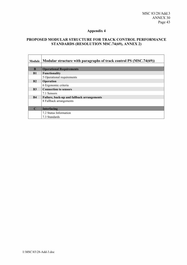
MSC 83/28/Add.3 ANNEX 30
Page 43
I:\MSC\83\28-Add-3.doc
Appendix 4
PROPOSED MODULAR STRUCTURE FOR TRACK CONTROL PERFORMANCE STANDARDS (RESOLUTION MSC.74(69), ANNEX 2)
Module Modular structure with paragraphs of track control PS (MSC.74(69))
B Operational Requirements B1 Functionality
5 Operational requirements B2 Operation
6 Ergonomic criteria B3 Connection to sensors
7.1 Sensors B4 Failure, back-up and fallback arrangements
8 Fallback arrangements
C Interfacing 7.2 Status Information 7.3 Standards
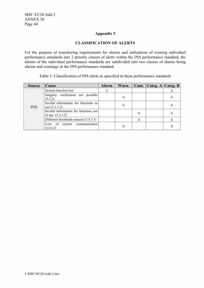
MSC 83/28/Add.3 ANNEX 30 Page 44
I:\MSC\83\28-Add-3.doc
Appendix 5
CLASSIFICATION OF ALERTS For the purpose of transferring requirements for alarms and indications of existing individual performance standards into 3 priority classes of alerts within the INS performance standard, the alarms of the individual performance standards are subdivided into two classes of alarms being alarms and warnings in the INS performance standard.
Table 1: Classification of INS alerts as specified in these performance standards
Source Cause Alarm Warn. Caut. Categ. A Categ. BSystem function lost X X Integrity verification not possible (5.5.5) X X Invalid information for functions in use (5.3.1.2) X X Invalid information for functions not in use (5.3.1.2) X X Different thresholds entered (5.4.3.3) X X
INS
Loss of system communication (12.6.2) X X

MSC 83/28/Add.3 ANNEX 30
Page 45
I:\MSC\83\28-Add-3.doc
Table 2: Classification for INS for alerts specified in the individual equipment performance standards
Source Cause Alarm Warn. Caut. Categ. A Categ. BFailure or reduction in power supply X X Off heading alarm X X Heading
control systems Heading monitor (deviation from
second heading source) X X Early course change indication (track control via waypoints) X X Actual course change indication X X Wheel over line (actual course change indication not acknowledged) 1) alarm 2) back-up navigator alarm
X X
Failure or reduction in power supply X X Position monitor X X Heading monitor X X Sensor failure (heading, position, speed) 1) alarm 2) back-up navigator alarm
X X
Cross-track alarm X X Course difference (heading deviates from track course) X X
Track Control systems
Low speed alarm X X Positioning system failure X X Crossing safety contour X X Deviation from planned route � off-track alarm X X Area with special conditions � cross the boundary X* X* X Approach to critical point X X Different geodetic datum X X System malfunction X X
ECDIS
(system malfunction of backup device) X X Target capacity X X CPA/TCPA alarm X X Acquisition/activation zone X X Lost target alarm X X
RADAR/ AIS
Failure of any signal or sensor in use X X HDOP exceeded X X No calculation of position X Loss of position X X Loss of differential signal X X
Differential corrections not applied X X
GNSS
Differential integrity status X X

MSC 83/28/Add.3 ANNEX 30 Page 46
I:\MSC\83\28-Add-3.doc
Depth below keel alarm X X Echo
sounder
Failure or reduction in power supply X X
Gyro compass
System fault X X
Malfunction X X Bridge watch alarm
Power supply failure X X
X*: selected by the user.
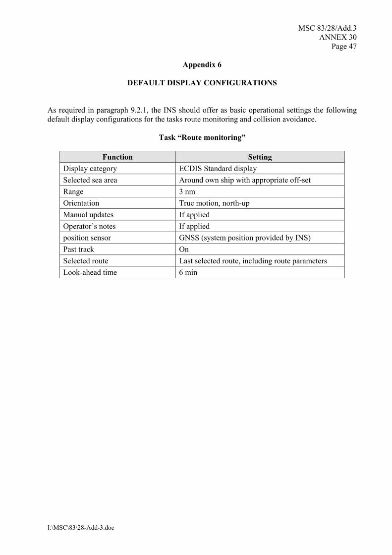
MSC 83/28/Add.3 ANNEX 30
Page 47
I:\MSC\83\28-Add-3.doc
Appendix 6
DEFAULT DISPLAY CONFIGURATIONS
As required in paragraph 9.2.1, the INS should offer as basic operational settings the following default display configurations for the tasks route monitoring and collision avoidance.
Task �Route monitoring�
Function Setting Display category ECDIS Standard display Selected sea area Around own ship with appropriate off-set Range 3 nm Orientation True motion, north-up Manual updates If applied Operator�s notes If applied position sensor GNSS (system position provided by INS) Past track On Selected route Last selected route, including route parameters Look-ahead time 6 min
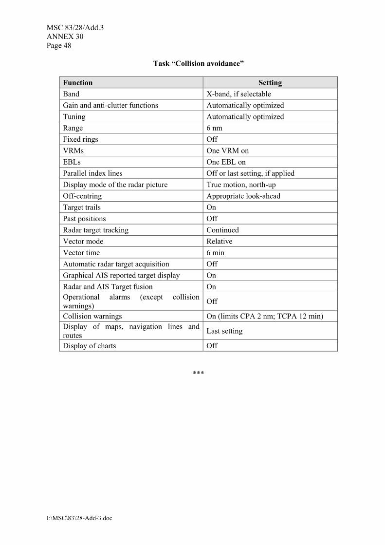
MSC 83/28/Add.3 ANNEX 30 Page 48
I:\MSC\83\28-Add-3.doc
Task �Collision avoidance�
Function Setting Band X-band, if selectable Gain and anti-clutter functions Automatically optimized Tuning Automatically optimized Range 6 nm Fixed rings Off VRMs One VRM on EBLs One EBL on Parallel index lines Off or last setting, if applied Display mode of the radar picture True motion, north-up Off-centring Appropriate look-ahead Target trails On Past positions Off Radar target tracking Continued Vector mode Relative Vector time 6 min Automatic radar target acquisition Off Graphical AIS reported target display On Radar and AIS Target fusion On Operational alarms (except collision warnings) Off
Collision warnings On (limits CPA 2 nm; TCPA 12 min) Display of maps, navigation lines and routes Last setting
Display of charts Off
***


![Recalling Mother - Esplanade/media/events media/2016/r/recalling... · Recalling Mother is perhaps the first and only theatrical ... tight script ... [this] ... recently appeared](https://static.fdocuments.net/doc/165x107/5b7821937f8b9ad3338e9e3e/recalling-mother-esplanade-mediaevents-media2016rrecalling-recalling.jpg)