An automotive vehicle dynamics prototyping platform based ...
13
Turk J Elec Eng & Comp Sci (2013) 21: 439 – 451 c T ¨ UB ˙ ITAK doi:10.3906/elk-1109-22 Turkish Journal of Electrical Engineering & Computer Sciences http://journals.tubitak.gov.tr/elektrik/ Research Article An automotive vehicle dynamics prototyping platform based on a remote control model car Selim SOLMAZ 1,∗ , T¨ urker COS ¸KUN 2 1 Department of Mechanical Engineering, Gediz University, Menemen, ˙ Izmir 35665, Turkey 2 Department of Electrical & Electronics Engineering, Bilkent University Ankara, 06800, Turkey Received: 13.09.2011 • Accepted: 25.01.2012 • Published Online: 22.03.2013 • Printed: 22.04.2013 Abstract: The use of a modified remote control (RC) model car as a vehicle dynamics testing and development platform is detailed. Vehicle dynamics testing is an important aspect of automotive engineering and it plays a key role during the design and tuning of active safety control systems. Considering the fact that such tests are conducted at great expense, scaled model cars can potentially be used to help with the process to reduce the costs. With this view, we instrument and develop a standard electric RC model car into a vehicle dynamics testing platform. We then implement 2 representative active safety control applications based on this platform, namely an antilock brake system using open-loop pulse brake control and a roll-over prevention system utilizing lateral acceleration feedback. Both applications are presented with sensor measurements and the effectiveness of the suggested control algorithms are demonstrated. Key words: Vehicle dynamics, active vehicle safety, scale model car dynamics, antilock brake system, rollover prevention 1. Introduction In modern motor vehicles, the dynamic response characteristic is an important feature affecting consumer preferences. High quality cars are often described with their own specific driving feel and response. Vehicle dynamics are also associated with the on-road safety and sense of security of a given vehicle. It is known that automotive manufacturers spend much time and effort to ensure a certain acceptable level of dynamic stability and response characteristics while designing new models. With such important consequences, the analysis of vehicle dynamics has developed into an important aspect of road vehicle design. Analysis of vehicle dynamic response helps in understanding the vehicle behavior under changing road and vehicle operating conditions. Once a safety-critical condition is identified, it is either mitigated by a design modification resulting in enhanced dynamic response or by employing an active feedback safety control system. As design modifications usually end up with a trade-off between vehicle safety and comfort, the use of active safety systems is usually preferred by auto manufacturers. Both approaches are quite costly and require much testing time and development effort. Active vehicle safety systems are feedback control mechanisms that improve on-road vehicle safety. Such systems typically sense the adverse dynamic condition with on-board inertial sensors and then utilize actuators such as active steering, active suspension, differential braking, active differential, and active antiroll bar to mitigate the problem. See [1] for a review, and see [2] and [3] for examples of such active vehicle safety control applications. Nowadays, it is a common practice to have many active safety control systems as part of the ∗ Correspondence: [email protected] 439
Transcript of An automotive vehicle dynamics prototyping platform based ...
Turk J Elec Eng & Comp Sci
(2013) 21: 439 – 451
c© TUBITAK
doi:10.3906/elk-1109-22
Turkish Journal of Electrical Engineering & Computer Sciences
http :// journa l s . tub i tak .gov . t r/e lektr ik/
Research Article
An automotive vehicle dynamics prototyping platform based on a remote control
model car
Selim SOLMAZ1,∗, Turker COSKUN2
1Department of Mechanical Engineering, Gediz University, Menemen, Izmir 35665, Turkey2Department of Electrical & Electronics Engineering, Bilkent University Ankara, 06800, Turkey
Received: 13.09.2011 • Accepted: 25.01.2012 • Published Online: 22.03.2013 • Printed: 22.04.2013
Abstract:The use of a modified remote control (RC) model car as a vehicle dynamics testing and development platform
is detailed. Vehicle dynamics testing is an important aspect of automotive engineering and it plays a key role during the
design and tuning of active safety control systems. Considering the fact that such tests are conducted at great expense,
scaled model cars can potentially be used to help with the process to reduce the costs. With this view, we instrument and
develop a standard electric RC model car into a vehicle dynamics testing platform. We then implement 2 representative
active safety control applications based on this platform, namely an antilock brake system using open-loop pulse brake
control and a roll-over prevention system utilizing lateral acceleration feedback. Both applications are presented with
sensor measurements and the effectiveness of the suggested control algorithms are demonstrated.
Key words: Vehicle dynamics, active vehicle safety, scale model car dynamics, antilock brake system, rollover prevention
1. Introduction
In modern motor vehicles, the dynamic response characteristic is an important feature affecting consumerpreferences. High quality cars are often described with their own specific driving feel and response. Vehicledynamics are also associated with the on-road safety and sense of security of a given vehicle. It is known thatautomotive manufacturers spend much time and effort to ensure a certain acceptable level of dynamic stabilityand response characteristics while designing new models. With such important consequences, the analysis ofvehicle dynamics has developed into an important aspect of road vehicle design.
Analysis of vehicle dynamic response helps in understanding the vehicle behavior under changing roadand vehicle operating conditions. Once a safety-critical condition is identified, it is either mitigated by a designmodification resulting in enhanced dynamic response or by employing an active feedback safety control system.As design modifications usually end up with a trade-off between vehicle safety and comfort, the use of activesafety systems is usually preferred by auto manufacturers. Both approaches are quite costly and require muchtesting time and development effort.
Active vehicle safety systems are feedback control mechanisms that improve on-road vehicle safety. Suchsystems typically sense the adverse dynamic condition with on-board inertial sensors and then utilize actuatorssuch as active steering, active suspension, differential braking, active differential, and active antiroll bar tomitigate the problem. See [1] for a review, and see [2] and [3] for examples of such active vehicle safety controlapplications. Nowadays, it is a common practice to have many active safety control systems as part of the
∗Correspondence: [email protected]
439
SOLMAZ and COSKUN/Turk J Elec Eng & Comp Sci
standard vehicle configuration. Some well-known examples of these are the antilock braking system (ABS),
electronic stability control (ESC) [4], and roll-over prevention (ROP) [2, 3, 5] systems. Development and tuningof such active safety control systems are usually done on real preproduction vehicles at a great expense.
Use of scaled models is quite common for aerodynamic design and optimization studies in the aerospaceindustry for proving numerical studies [6]. Similar studies are also conducted in the automotive industry,particularly in motor sports. The use of scale models for feedback control system design is again a commonpractice in the aerospace industry [7] since it is safer and much cheaper to prototype a new control system
and/or a vehicle concept on a relatively cheap scale model. While there are a very few recent academic studies
conducted on the use of scale models for vehicle dynamics testing and prototyping, such as [8], [9], [10], [11],
[12], and [13], we believe that such vehicle dynamics test beds are not common in the automotive industry since
we could not locate any reference reports and/or papers citing the use of such scale-vehicle models from theindustry.
Motivated by the above facts, we describe the development stages of a cheap remote control (RC) model
car as a hardware-in-loop (HIL) vehicle dynamics analysis platform in the current paper. In our design, a mobilePC serves as a real-time electronic control unit for processing on-board vehicle sensors and also for triggeringactive feedback control algorithms. The designed system can be used as a low-cost rapid prototyping system foradvanced active vehicle safety system development that can potentially reduce the development costs of suchsystems. We demonstrate implementation of 2 safety control systems on this platform, namely an ABS systemusing an open-loop pulse brake control system and a ROP system utilizing lateral acceleration feedback. Weemphasize that the main difference (and the advantage) of the hardware setup that we describe here from theliterature is the fact that the HIL setup is directly controlled by the MATLAB–Simulink environment ratherthan an embedded computer, which simplifies its prototyping ability for implementing and testing new controllerdesigns.
Throughout the paper, we describe all the development stages of the vehicle platform, including thedesign of interface between the RC car and computer, integration of an inertial wireless motion sensing hardwareaccessory for kinaesthetic expression (SHAKE) SK6 sensor (see http://code.google.com/p/shake-drivers/) onthe vehicle, and the coding of the feedback control system using MATLAB–Simulink. We demonstrate theefficacy of our experimental setup with real measurement data.
2. Specification of the hardware and its interfaces
The basis component we use in this work is a RC car from LOSI (Strike 1/10 Scale Electric Short Course
Truck). The car runs on a Ni/Mh battery pack and is controlled via the LOSI LSR-3000 radio controller,which operates at 2.4 GHz radio frequency for communicating with the receiver module on the car. The radiotransmitter contains a throttle trigger connected to a potentiometer (i.e. a circular transducer) for controllinglongitudinal motion, and a circular steering wheel potentiometer to control the vehicle’s lateral movement.There are also several knobs for calibration (e.g., for throttle and steering trims and for setting DC gains on
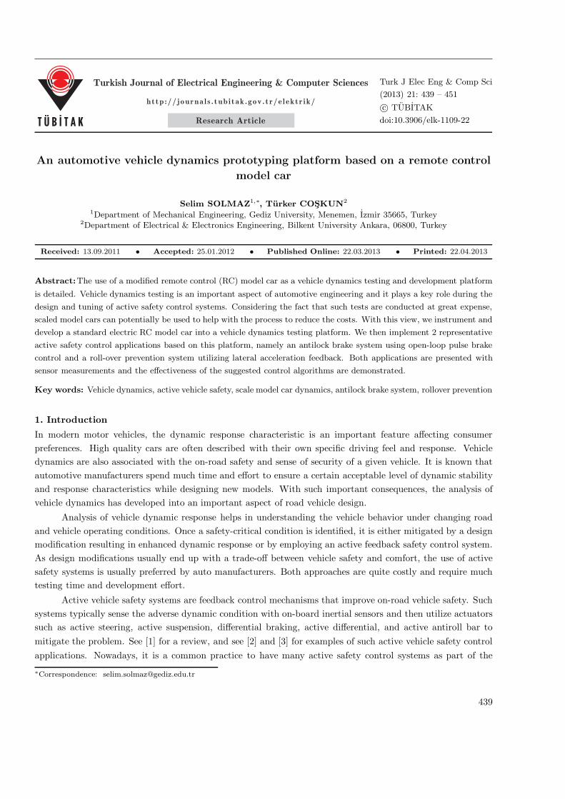
the respective control channels). An additional weight of 2.3 kg is added on top of the car, as seen in Figure 1,to make the vehicle top-heavy, resulting in roll instability, which was required to test the anti-rollover controlalgorithm we implemented.
The hardware and software design aspect of this work is mainly related to the interfacing of the modelcar’s remote controller and the SHAKE SK6 sensor with the computer. The computer here serves both as adata acquisition system and as an electronic control unit for triggering control commands. The software aspect
440
SOLMAZ and COSKUN/Turk J Elec Eng & Comp Sci
Figure 1. LOSI electric RC car with additional weight on top.
of the work was implemented in MATLAB–Simulink.
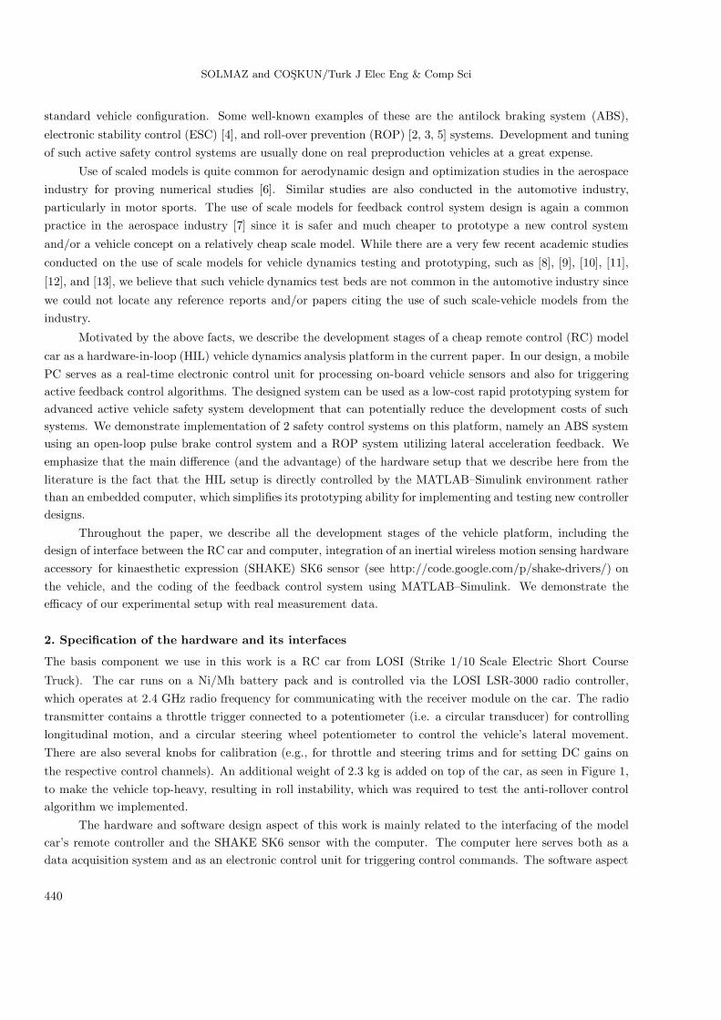
In order to interface the remote controller with the computer, we used the LabJack U3-LV I/O board
seen in Figure 2, which has 2 analog outputs (these were used for steering and throttle control, respectively),
more than 10 digital I/Os (2 of which were set as analog inputs for monitoring the steering and throttle signals),and other additional features such as timers and counters.
Figure 2. Labjack U3 I/O board.
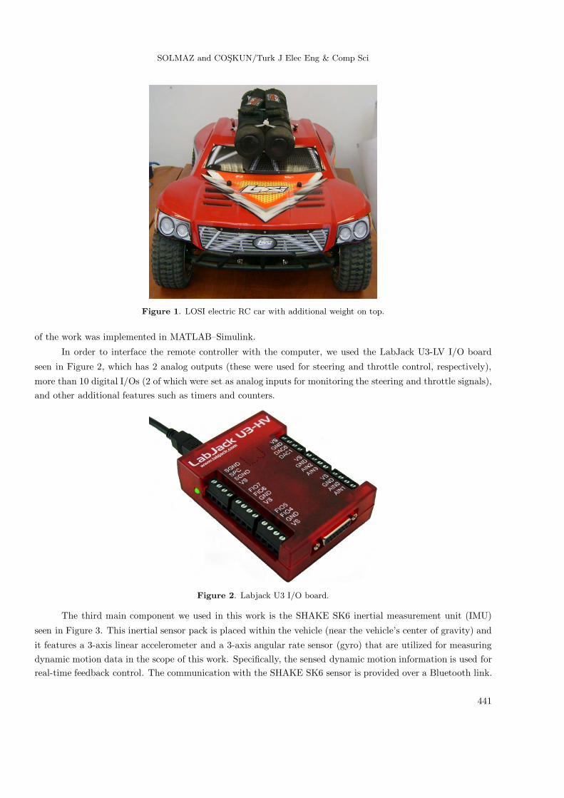
The third main component we used in this work is the SHAKE SK6 inertial measurement unit (IMU)
seen in Figure 3. This inertial sensor pack is placed within the vehicle (near the vehicle’s center of gravity) and
it features a 3-axis linear accelerometer and a 3-axis angular rate sensor (gyro) that are utilized for measuringdynamic motion data in the scope of this work. Specifically, the sensed dynamic motion information is used forreal-time feedback control. The communication with the SHAKE SK6 sensor is provided over a Bluetooth link.
441
SOLMAZ and COSKUN/Turk J Elec Eng & Comp Sci
Table 1. Steering potentiometer.
Wheel position Output (Volts)Neutral 1.44Full left 0.13
Full right 2.72
Once the connection is configured between the sensor and the computer, communication is established over theserial COM port. The real-time sensor data are processed in MATLAB–Simulink and then used to monitorand generate trigger signals for engaging the predefined control actions when certain dynamic conditions areprovided. The control actions are also enabled by the MATLAB–Simulink environment, which are simply inthe form of variable throttle and steering angle control. In demonstrating the system for prototyping of activesafety systems, the 2 control inputs (active steering and active throttle control) are used for rollover preventionand for obtaining a pulse-break system. In this respect, real-time data acquisition and processing from the IMUsensor is a critical feature of the overall system.
Figure 3. SHAKE SK6 sensor.
2.1. RC–computer interface
At first glance, the 2 main components of the remote controller (LSR 3000 DSM transmitter) are the steering
wheel angle and the throttle/brake trigger angle. The steering wheel and the throttle/brake trigger are eachconnected to a potentiometer, on which the potential difference between the 2 terminals can be set by adjustingthe positioning of the wheel and the trigger.
In order to interface the vehicle control inputs with the computer, we recorded the neutral and limitpotential difference values on the potentiometers. The potentiometers under interest consists of 3 terminals:ground, supply, and output terminals. The position of the wheel/trigger determines directly the output voltageof the potentiometer. In Tables 1 and 2, the measured neutral and limit output voltages on the potentiometersfor steering and throttle/brake can respectively be seen.
As one can see from Tables 1 and 2, in order to control the car, a voltage in the 0− 3 V range should beapplied to the terminals, which are initially connected to the output terminals of the potentiometers. For thisproject, we disconnected the terminals from the potentiometers and instead connected them to an outer DC
442
SOLMAZ and COSKUN/Turk J Elec Eng & Comp Sci
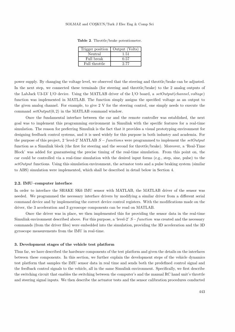
Table 2. Throttle/brake potentiometer.
Trigger position Output (Volts)Neutral 1.51
Full break 0.57Full throttle 2.77
power supply. By changing the voltage level, we observed that the steering and throttle/brake can be adjusted.
In the next step, we connected these terminals (for steering and throttle/brake) to the 2 analog outputs of
the LabJack U3-LV I/O device. Using the MATLAB driver of the I/O board, a setOutput(channel, voltage)function was implemented in MATLAB. The function simply assigns the specified voltage as an output tothe given analog channel. For example, to give 2 V for the steering control, one simply needs to execute thecommand setOutput(0, 2) in the MATLAB command window.
Once the fundamental interface between the car and the remote controller was established, the nextgoal was to implement this programming environment in Simulink with the specific features for a real-timesimulation. The reason for preferring Simulink is the fact that it provides a visual prototyping environment fordesigning feedback control systems, and it is used widely for this purpose in both industry and academia. Forthe purpose of this project, 2 ‘level-2’ MATLAB S − functions were programmed to implement the setOutput
function as a Simulink block (the first for steering and the second for throttle/brake). Moreover, a ‘Real-TimeBlock’ was added for guaranteeing the precise timing of the real-time simulation. From this point on, thecar could be controlled via a real-time simulation with the desired input forms (e.g., step, sine, pulse) to the
setOutput functions. Using this simulation environment, the actuator tests and a pulse braking system (similar
to ABS) simulation were implemented, which shall be described in detail below in Section 4.
2.2. IMU–computer interface
In order to interface the SHAKE SK6 IMU sensor with MATLAB, the MATLAB driver of the sensor wasneeded. We programmed the necessary interface drivers by modifying a similar driver from a different serialcommand device and by implementing the correct device control registers. With the modifications made on thedriver, the 3 acceleration and 3 gyroscope components can be read on MATLAB.
Once the driver was in place, we then implemented this for providing the sensor data in the real-timeSimulink environment described above. For this purpose, a ‘level-2’ S−function was created and the necessarycommands (from the driver files) were embedded into the simulation, providing the 3D acceleration and the 3Dgyroscope measurements from the IMU in real-time.
3. Development stages of the vehicle test platform
Thus far, we have described the hardware components of the test platform and given the details on the interfacesbetween these components. In this section, we further explain the development steps of the vehicle dynamicstest platform that samples the IMU sensor data in real time and sends both the predefined control signal andthe feedback control signals to the vehicle, all in the same Simulink environment. Specifically, we first describethe switching circuit that enables the switching between the computer’s and the manual RC hand unit’s throttleand steering signal inputs. We then describe the actuator tests and the sensor calibration procedures conducted
443
SOLMAZ and COSKUN/Turk J Elec Eng & Comp Sci
in MATLAB–Simulink. Finally, we describe an alternative interface between the car and the computer withoutusing the switching circuit, which enables use of both the RC unit and computer inputs at the same time.
3.1. Switching circuit preparation
The switching circuit was designed to allow the user to decide on the vehicle control input mechanism. Itenables control of the car by either the RC hand-unit or by predefined computer inputs.
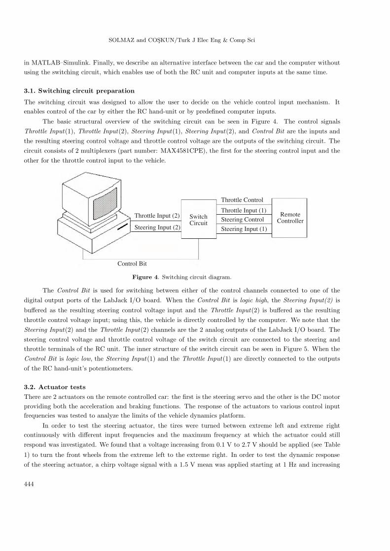
The basic structural overview of the switching circuit can be seen in Figure 4. The control signalsThrottle Input(1), Throttle Input(2), Steering Input(1), Steering Input(2), and Control Bit are the inputs andthe resulting steering control voltage and throttle control voltage are the outputs of the switching circuit. Thecircuit consists of 2 multiplexers (part number: MAX4581CPE), the first for the steering control input and theother for the throttle control input to the vehicle.
Throttle Input (2)
Steering Input (2)
Control Bit
SwitchCircuit
RemoteController
Throttle Control
Throttle Input (1)
Steering Control
Steering Input (1)
Figure 4. Switching circuit diagram.
The Control Bit is used for switching between either of the control channels connected to one of thedigital output ports of the LabJack I/O board. When the Control Bit is logic high, the Steering Input(2) is
buffered as the resulting steering control voltage input and the Throttle Input(2) is buffered as the resultingthrottle control voltage input; using this, the vehicle is directly controlled by the computer. We note that theSteering Input(2) and the Throttle Input(2) channels are the 2 analog outputs of the LabJack I/O board. Thesteering control voltage and throttle control voltage of the switch circuit are connected to the steering andthrottle terminals of the RC unit. The inner structure of the switch circuit can be seen in Figure 5. When theControl Bit is logic low, the Steering Input(1) and the Throttle Input(1) are directly connected to the outputsof the RC hand-unit’s potentiometers.
3.2. Actuator testsThere are 2 actuators on the remote controlled car: the first is the steering servo and the other is the DC motorproviding both the acceleration and braking functions. The response of the actuators to various control inputfrequencies was tested to analyze the limits of the vehicle dynamics platform.
In order to test the steering actuator, the tires were turned between extreme left and extreme rightcontinuously with different input frequencies and the maximum frequency at which the actuator could stillrespond was investigated. We found that a voltage increasing from 0.1 V to 2.7 V should be applied (see Table
1) to turn the front wheels from the extreme left to the extreme right. In order to test the dynamic responseof the steering actuator, a chirp voltage signal with a 1.5 V mean was applied starting at 1 Hz and increasing
444
SOLMAZ and COSKUN/Turk J Elec Eng & Comp Sci
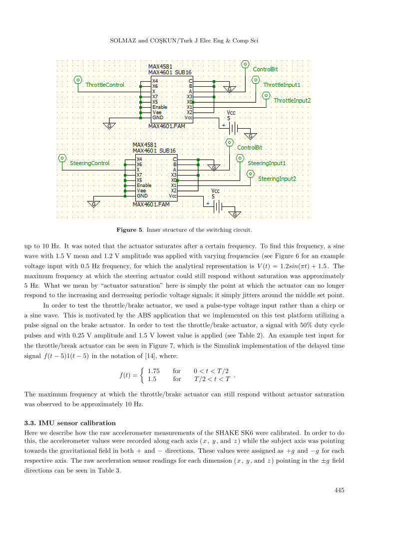
Figure 5. Inner structure of the switching circuit.
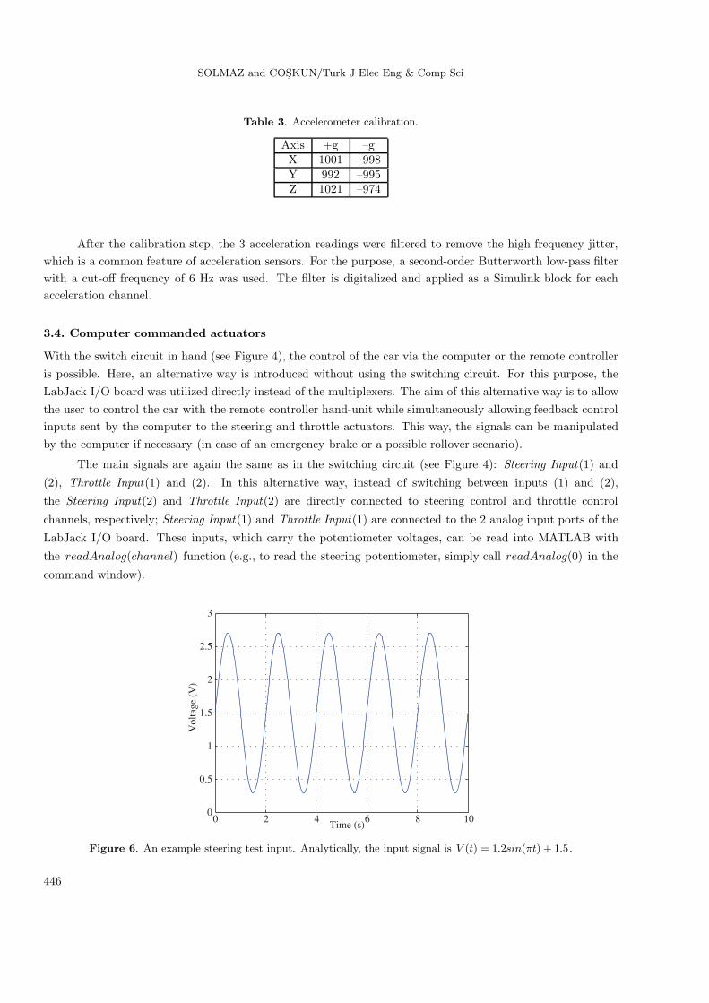
up to 10 Hz. It was noted that the actuator saturates after a certain frequency. To find this frequency, a sinewave with 1.5 V mean and 1.2 V amplitude was applied with varying frequencies (see Figure 6 for an example
voltage input with 0.5 Hz frequency, for which the analytical representation is V (t) = 1.2sin(πt) + 1.5. Themaximum frequency at which the steering actuator could still respond without saturation was approximately5 Hz. What we mean by “actuator saturation” here is simply the point at which the actuator can no longerrespond to the increasing and decreasing periodic voltage signals; it simply jitters around the middle set point.
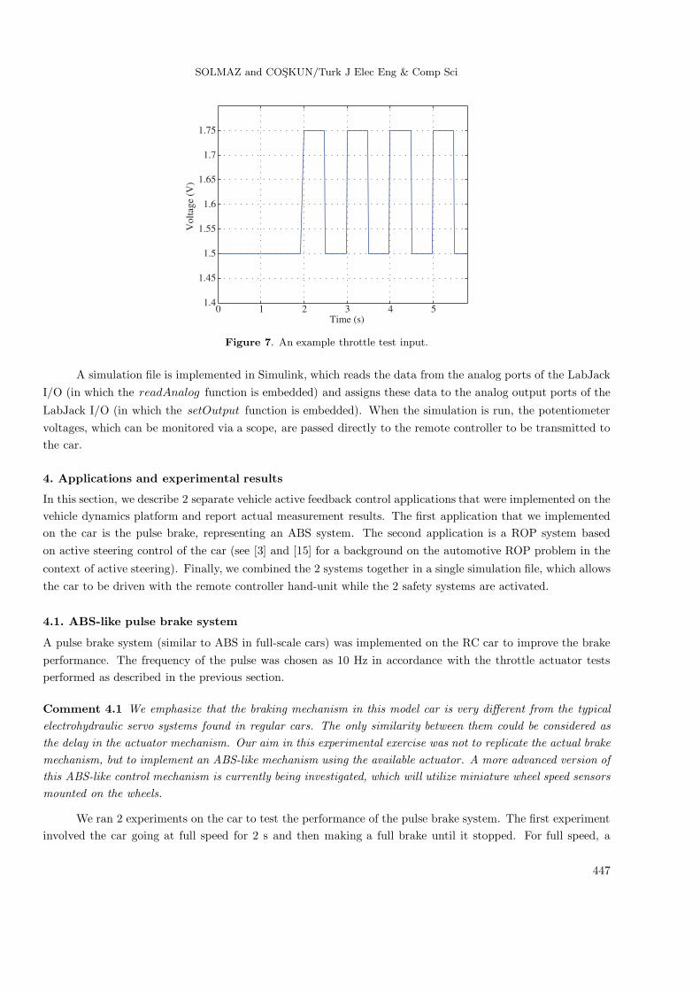
In order to test the throttle/brake actuator, we used a pulse-type voltage input rather than a chirp ora sine wave. This is motivated by the ABS application that we implemented on this test platform utilizing apulse signal on the brake actuator. In order to test the throttle/brake actuator, a signal with 50% duty cycle
pulses and with 0.25 V amplitude and 1.5 V lowest value is applied (see Table 2). An example test input for
the throttle/break actuator can be seen in Figure 7, which is the Simulink implementation of the delayed time
signal f(t − 5)1(t − 5) in the notation of [14], where:
f(t) ={
1.75 for 0 < t < T/21.5 for T/2 < t < T
.
The maximum frequency at which the throttle/brake actuator can still respond without actuator saturationwas observed to be approximately 10 Hz.
3.3. IMU sensor calibrationHere we describe how the raw accelerometer measurements of the SHAKE SK6 were calibrated. In order to dothis, the accelerometer values were recorded along each axis (x , y , and z ) while the subject axis was pointingtowards the gravitational field in both + and − directions. These values were assigned as +g and −g for eachrespective axis. The raw acceleration sensor readings for each dimension (x , y , and z ) pointing in the ±g fielddirections can be seen in Table 3.
445
SOLMAZ and COSKUN/Turk J Elec Eng & Comp Sci
Table 3. Accelerometer calibration.
Axis +g –gX 1001 –998Y 992 –995Z 1021 –974
After the calibration step, the 3 acceleration readings were filtered to remove the high frequency jitter,which is a common feature of acceleration sensors. For the purpose, a second-order Butterworth low-pass filterwith a cut-off frequency of 6 Hz was used. The filter is digitalized and applied as a Simulink block for eachacceleration channel.
3.4. Computer commanded actuators
With the switch circuit in hand (see Figure 4), the control of the car via the computer or the remote controlleris possible. Here, an alternative way is introduced without using the switching circuit. For this purpose, theLabJack I/O board was utilized directly instead of the multiplexers. The aim of this alternative way is to allowthe user to control the car with the remote controller hand-unit while simultaneously allowing feedback controlinputs sent by the computer to the steering and throttle actuators. This way, the signals can be manipulatedby the computer if necessary (in case of an emergency brake or a possible rollover scenario).
The main signals are again the same as in the switching circuit (see Figure 4): Steering Input(1) and
(2), Throttle Input(1) and (2). In this alternative way, instead of switching between inputs (1) and (2),
the Steering Input(2) and Throttle Input(2) are directly connected to steering control and throttle control
channels, respectively; Steering Input(1) and Throttle Input(1) are connected to the 2 analog input ports of the
LabJack I/O board. These inputs, which carry the potentiometer voltages, can be read into MATLAB with
the readAnalog(channel) function (e.g., to read the steering potentiometer, simply call readAnalog(0) in the
command window).
0 2 4 6 8 100
0.5
1
1.5
2
2.5
3
Time (s)
Vol
tage
(V
)
Figure 6. An example steering test input. Analytically, the input signal is V (t) = 1.2sin(πt) + 1.5.
446
SOLMAZ and COSKUN/Turk J Elec Eng & Comp Sci
0 1 2 3 4 51.4
1.45
1.5
1.55
1.6
1.65
1.7
1.75
Vol
tage
(V
)
Time (s)
Figure 7. An example throttle test input.
A simulation file is implemented in Simulink, which reads the data from the analog ports of the LabJackI/O (in which the readAnalog function is embedded) and assigns these data to the analog output ports of the
LabJack I/O (in which the setOutput function is embedded). When the simulation is run, the potentiometervoltages, which can be monitored via a scope, are passed directly to the remote controller to be transmitted tothe car.
4. Applications and experimental results
In this section, we describe 2 separate vehicle active feedback control applications that were implemented on thevehicle dynamics platform and report actual measurement results. The first application that we implementedon the car is the pulse brake, representing an ABS system. The second application is a ROP system basedon active steering control of the car (see [3] and [15] for a background on the automotive ROP problem in the
context of active steering). Finally, we combined the 2 systems together in a single simulation file, which allowsthe car to be driven with the remote controller hand-unit while the 2 safety systems are activated.
4.1. ABS-like pulse brake system
A pulse brake system (similar to ABS in full-scale cars) was implemented on the RC car to improve the brakeperformance. The frequency of the pulse was chosen as 10 Hz in accordance with the throttle actuator testsperformed as described in the previous section.
Comment 4.1 We emphasize that the braking mechanism in this model car is very different from the typicalelectrohydraulic servo systems found in regular cars. The only similarity between them could be considered asthe delay in the actuator mechanism. Our aim in this experimental exercise was not to replicate the actual brakemechanism, but to implement an ABS-like mechanism using the available actuator. A more advanced version ofthis ABS-like control mechanism is currently being investigated, which will utilize miniature wheel speed sensorsmounted on the wheels.
We ran 2 experiments on the car to test the performance of the pulse brake system. The first experimentinvolved the car going at full speed for 2 s and then making a full brake until it stopped. For full speed, a
447
SOLMAZ and COSKUN/Turk J Elec Eng & Comp Sci
voltage of 2.5 V, and for full brake, a voltage of 0.9 V were applied to the throttle terminal; the nominal valueis again 1.5 V (see Table 2).
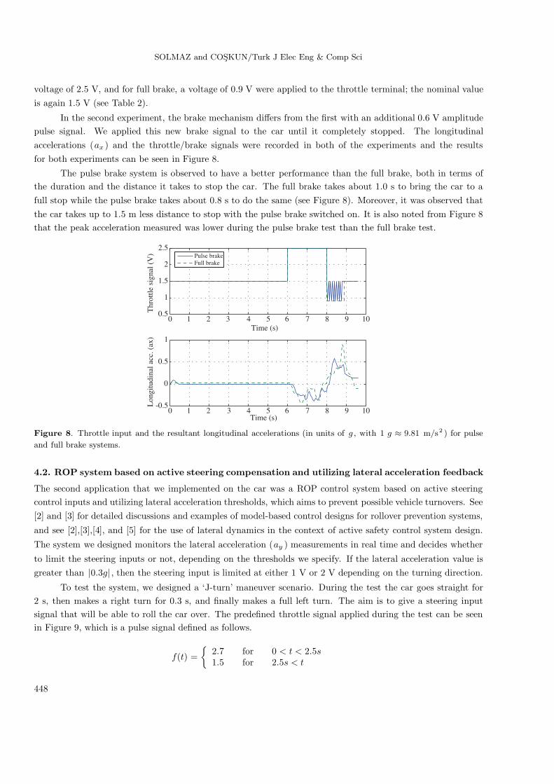
In the second experiment, the brake mechanism differs from the first with an additional 0.6 V amplitudepulse signal. We applied this new brake signal to the car until it completely stopped. The longitudinalaccelerations (ax ) and the throttle/brake signals were recorded in both of the experiments and the resultsfor both experiments can be seen in Figure 8.
The pulse brake system is observed to have a better performance than the full brake, both in terms ofthe duration and the distance it takes to stop the car. The full brake takes about 1.0 s to bring the car to afull stop while the pulse brake takes about 0.8 s to do the same (see Figure 8). Moreover, it was observed thatthe car takes up to 1.5 m less distance to stop with the pulse brake switched on. It is also noted from Figure 8that the peak acceleration measured was lower during the pulse brake test than the full brake test.
0 1 2 3 4 5 6 7 8 9 100.5
1
1.5
2
2.5
Time (s)
Pulse brakeFull brake
0 1 2 3 4 5 6 7 8 9 10-0.5
0
0.5
1
Time (s)
Lon
gitu
dina
l acc
. (ax
)T
hrot
tle s
igna
l (V
)
Figure 8. Throttle input and the resultant longitudinal accelerations (in units of g , with 1 g ≈ 9.81 m/s2 ) for pulse
and full brake systems.
4.2. ROP system based on active steering compensation and utilizing lateral acceleration feedback
The second application that we implemented on the car was a ROP control system based on active steeringcontrol inputs and utilizing lateral acceleration thresholds, which aims to prevent possible vehicle turnovers. See[2] and [3] for detailed discussions and examples of model-based control designs for rollover prevention systems,
and see [2],[3],[4], and [5] for the use of lateral dynamics in the context of active safety control system design.
The system we designed monitors the lateral acceleration (ay ) measurements in real time and decides whether
to limit the steering inputs or not, depending on the thresholds we specify. If the lateral acceleration value isgreater than |0.3g| , then the steering input is limited at either 1 V or 2 V depending on the turning direction.
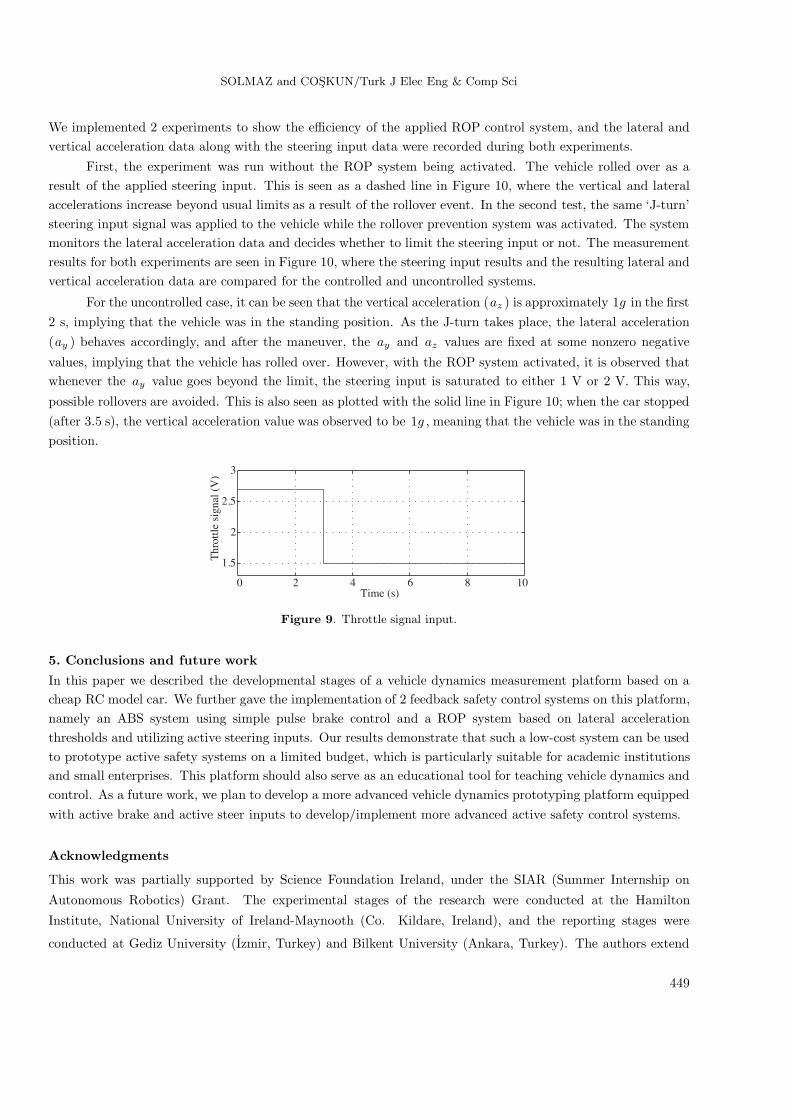
To test the system, we designed a ‘J-turn’ maneuver scenario. During the test the car goes straight for2 s, then makes a right turn for 0.3 s, and finally makes a full left turn. The aim is to give a steering inputsignal that will be able to roll the car over. The predefined throttle signal applied during the test can be seenin Figure 9, which is a pulse signal defined as follows.
f(t) ={
2.7 for 0 < t < 2.5s1.5 for 2.5s < t
448
SOLMAZ and COSKUN/Turk J Elec Eng & Comp Sci
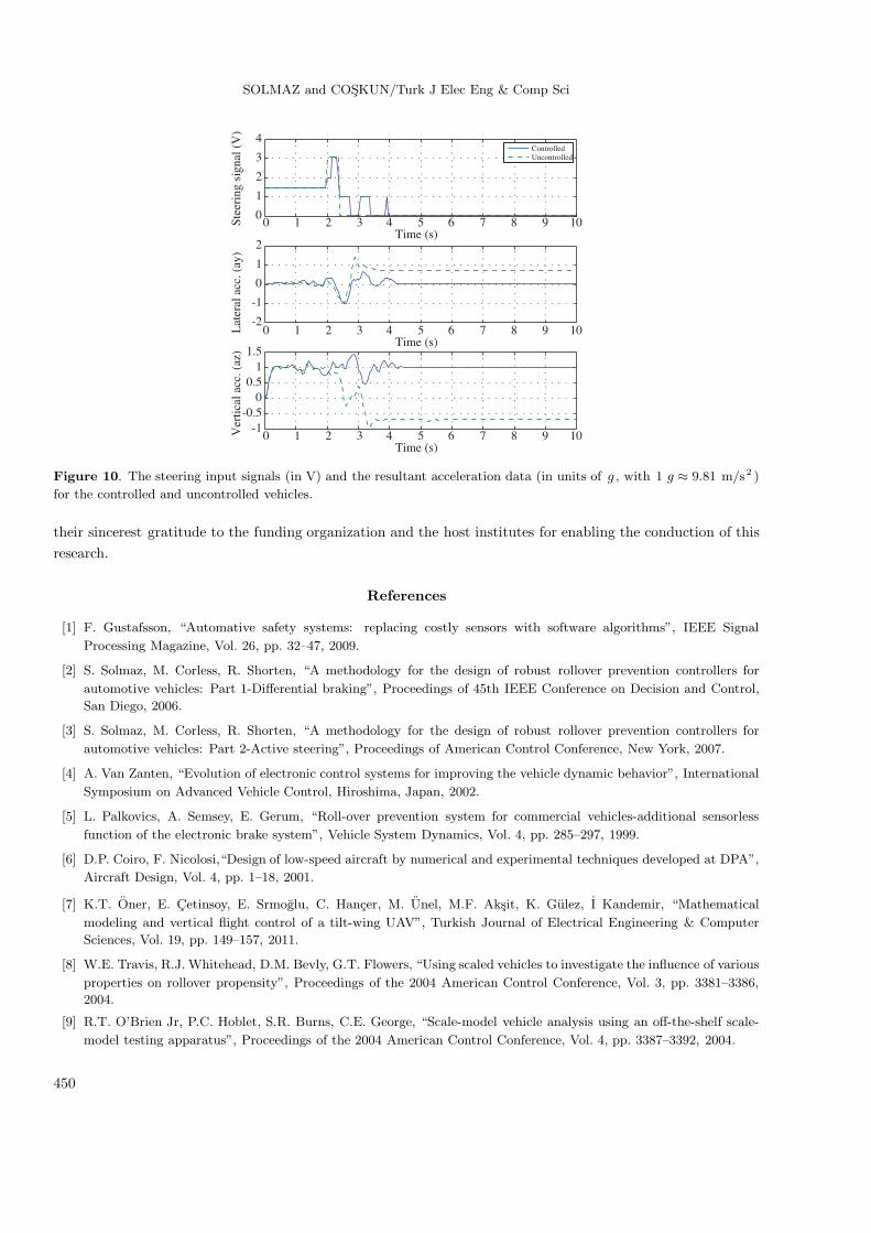
We implemented 2 experiments to show the efficiency of the applied ROP control system, and the lateral andvertical acceleration data along with the steering input data were recorded during both experiments.
First, the experiment was run without the ROP system being activated. The vehicle rolled over as aresult of the applied steering input. This is seen as a dashed line in Figure 10, where the vertical and lateralaccelerations increase beyond usual limits as a result of the rollover event. In the second test, the same ‘J-turn’steering input signal was applied to the vehicle while the rollover prevention system was activated. The systemmonitors the lateral acceleration data and decides whether to limit the steering input or not. The measurementresults for both experiments are seen in Figure 10, where the steering input results and the resulting lateral andvertical acceleration data are compared for the controlled and uncontrolled systems.
For the uncontrolled case, it can be seen that the vertical acceleration (az ) is approximately 1g in the first2 s, implying that the vehicle was in the standing position. As the J-turn takes place, the lateral acceleration(ay ) behaves accordingly, and after the maneuver, the ay and az values are fixed at some nonzero negative
values, implying that the vehicle has rolled over. However, with the ROP system activated, it is observed thatwhenever the ay value goes beyond the limit, the steering input is saturated to either 1 V or 2 V. This way,
possible rollovers are avoided. This is also seen as plotted with the solid line in Figure 10; when the car stopped(after 3.5 s), the vertical acceleration value was observed to be 1g , meaning that the vehicle was in the standingposition.
0 2 4 6 8 10
1.5
2
2.5
3
Thr
ottle
sig
nal (
V)
Time (s)
Figure 9. Throttle signal input.
5. Conclusions and future work
In this paper we described the developmental stages of a vehicle dynamics measurement platform based on acheap RC model car. We further gave the implementation of 2 feedback safety control systems on this platform,namely an ABS system using simple pulse brake control and a ROP system based on lateral accelerationthresholds and utilizing active steering inputs. Our results demonstrate that such a low-cost system can be usedto prototype active safety systems on a limited budget, which is particularly suitable for academic institutionsand small enterprises. This platform should also serve as an educational tool for teaching vehicle dynamics andcontrol. As a future work, we plan to develop a more advanced vehicle dynamics prototyping platform equippedwith active brake and active steer inputs to develop/implement more advanced active safety control systems.
Acknowledgments
This work was partially supported by Science Foundation Ireland, under the SIAR (Summer Internship on
Autonomous Robotics) Grant. The experimental stages of the research were conducted at the Hamilton
Institute, National University of Ireland-Maynooth (Co. Kildare, Ireland), and the reporting stages were
conducted at Gediz University (Izmir, Turkey) and Bilkent University (Ankara, Turkey). The authors extend
449
SOLMAZ and COSKUN/Turk J Elec Eng & Comp Sci
0 1 2 3 4 5 6 7 8 9 100
1
2
3
4
Stee
ring
sig
nal (
V)
Lat
eral
acc
. (ay
)V
ertic
al a
cc. (
az)
ControlledUncontrolled
-2
-1
0
1
2Time (s)
0 1 2 3 4 5 6 7 8 9 10Time (s)
0 1 2 3 4 5 6 7 8 9 10Time (s)
-1-0.5
00.5
11.5
Figure 10. The steering input signals (in V) and the resultant acceleration data (in units of g , with 1 g ≈ 9.81 m/s2 )
for the controlled and uncontrolled vehicles.
their sincerest gratitude to the funding organization and the host institutes for enabling the conduction of thisresearch.
References
[1] F. Gustafsson, “Automative safety systems: replacing costly sensors with software algorithms”, IEEE Signal
Processing Magazine, Vol. 26, pp. 32–47, 2009.
[2] S. Solmaz, M. Corless, R. Shorten, “A methodology for the design of robust rollover prevention controllers for
automotive vehicles: Part 1-Differential braking”, Proceedings of 45th IEEE Conference on Decision and Control,
San Diego, 2006.
[3] S. Solmaz, M. Corless, R. Shorten, “A methodology for the design of robust rollover prevention controllers for
automotive vehicles: Part 2-Active steering”, Proceedings of American Control Conference, New York, 2007.
[4] A. Van Zanten, “Evolution of electronic control systems for improving the vehicle dynamic behavior”, International
Symposium on Advanced Vehicle Control, Hiroshima, Japan, 2002.
[5] L. Palkovics, A. Semsey, E. Gerum, “Roll-over prevention system for commercial vehicles-additional sensorless
function of the electronic brake system”, Vehicle System Dynamics, Vol. 4, pp. 285–297, 1999.
[6] D.P. Coiro, F. Nicolosi,“Design of low-speed aircraft by numerical and experimental techniques developed at DPA”,
Aircraft Design, Vol. 4, pp. 1–18, 2001.
[7] K.T. Oner, E. Cetinsoy, E. Srmoglu, C. Hancer, M. Unel, M.F. Aksit, K. Gulez, I Kandemir, “Mathematical
modeling and vertical flight control of a tilt-wing UAV”, Turkish Journal of Electrical Engineering & Computer
Sciences, Vol. 19, pp. 149–157, 2011.
[8] W.E. Travis, R.J. Whitehead, D.M. Bevly, G.T. Flowers, “Using scaled vehicles to investigate the influence of various
properties on rollover propensity”, Proceedings of the 2004 American Control Conference, Vol. 3, pp. 3381–3386,
2004.
[9] R.T. O’Brien Jr, P.C. Hoblet, S.R. Burns, C.E. George, “Scale-model vehicle analysis using an off-the-shelf scale-
model testing apparatus”, Proceedings of the 2004 American Control Conference, Vol. 4, pp. 3387–3392, 2004.
450

SOLMAZ and COSKUN/Turk J Elec Eng & Comp Sci
[10] A. Liburdi, Development of a Scale Vehicle Dynamics Test Bed, MSc thesis, Department of Mechanical, Automotive,
and Materials Engineering, University of Windsor, Windsor, Canada, 2010.
[11] S. Brennan, A. Alleyne, “The Illinois Roadway Simulator: a mechatronic testbed for vehicle dynamics and control”,
IEEE Transactions on Mechatronics, Vol.5, pp. 349–59, 2000.
[12] S. Brennan, A. Alleyne, “Using a scale testbed: controller design and evaluation”, IEEE Control Systems Magazine,
Vol. 21, pp. 15–26, 2001.
[13] P. Yih, “Radio controlled car model as a vehicle dynamics test bed”, Dynamic Design Laboratory Research Report,
Stanford University, 2000. Available at http://www.cdr.stanford.edu/dynamic/rccar/rccar.pdf.
[14] K. Ogata, System Dynamics, 4th ed., Prentice Hall, Hoboken, NJ, USA, 2004.
[15] J. Ackermann, D. Odenthal,“Robust steering control for active rollover avoidance of vehicles with elevated center
of gravity”, Proceedings of International Conference on Advances in Vehicle Control and Safety, Amiens, France,
1998.
451