Agilent B1500A Programming Guide - Keysight · 2006-05-22 · Agilent B1500 Programming Guide,...
418
Agilent Technologies Agilent B1500A Semiconductor Device Analyzer Programming Guide
Transcript of Agilent B1500A Programming Guide - Keysight · 2006-05-22 · Agilent B1500 Programming Guide,...
Agilent B1500ASemiconductor Device Analyzer
Programming Guide
Agilent Technologies
Notices© Agilent Technologies 2005, 2006
No part of this manual may be reproduced in any form or by any means (including elec-tronic storage and retrieval or translation into a foreign language) without prior agree-ment and written consent from Agilent Technologies, Inc. as governed by United States and international copyright laws.
Manual Part NumberB1500-90011
EditionEdition 1, August 2005Edition 2, April 2006
Agilent Technologies, Inc.395 Page Mill Road Palo Alto, CA 94303 USA
WarrantyThe material contained in this docu-ment is provided “as is,” and is sub-ject to being changed, without notice, in future editions. Further, to the max-imum extent permitted by applicable law, Agilent disclaims all warranties, either express or implied, with regard to this manual and any information contained herein, including but not limited to the implied warranties of merchantability and fitness for a par-ticular purpose. Agilent shall not be liable for errors or for incidental or consequential damages in connec-tion with the furnishing, use, or per-formance of this document or of any information contained herein. Should Agilent and the user have a separate written agreement with warranty terms covering the material in this document that conflict with these terms, the warranty terms in the sep-arate agreement shall control.
Technology Licenses The hardware and/or software described in this document are furnished under a license and may be used or copied only in accor-dance with the terms of such license.
Restricted Rights LegendIf software is for use in the performance of a U.S. Government prime contract or subcon-tract, Software is delivered and licensed as “Commercial computer software” as defined in DFAR 252.227-7014 (June 1995), or as a “commercial item” as defined in FAR 2.101(a) or as “Restricted computer soft-ware” as defined in FAR 52.227-19 (June 1987) or any equivalent agency regulation or contract clause. Use, duplication or disclo-sure of Software is subject to Agilent Tech-nologies’ standard commercial license terms, and non-DOD Departments and Agencies of the U.S. Government will receive no greater than Restricted Rights as
defined in FAR 52.227-19(c)(1-2) (June 1987). U.S. Government users will receive no greater than Limited Rights as defined in FAR 52.227-14 (June 1987) or DFAR 252.227-7015 (b)(2) (November 1995), as applicable in any technical data.

In This Manual This manual provides the information to control the Agilent B1500 via GPIB interface using an external computer, and consists of the following chapters:
• “Programming Basics”
This chapter provides basic information to control the Agilent B1500.
• “Remote Mode Functions”
This chapter explains the functions of the Agilent B1500 in the remote mode.
• “Programming Examples”
This chapter lists the GPIB commands and explains the programming examples for each measurement mode or function. The examples have been written in the Microsoft Visual Basic .NET or the HP BASIC language.
• “Command Reference”
This chapter provides the complete reference of the GPIB commands of the Agilent B1500.
• “Error Messages”
This chapter lists the error codes, and explains them.
Microsoft, Windows, and Visual Basic are registered trademarks of Microsoft Corporation. All other trademarks are the
property of their respective owners.
Contents
1. Programming Basics
Before Starting . . . . . . . . . . . . . . . . . . . . . . . . . . . . . . . . . . . . . . . . . . . . . . . . . . . . 1-3About Examples . . . . . . . . . . . . . . . . . . . . . . . . . . . . . . . . . . . . . . . . . . . . . . . . . 1-4
Getting Started . . . . . . . . . . . . . . . . . . . . . . . . . . . . . . . . . . . . . . . . . . . . . . . . . . . . 1-5To Reset the Agilent B1500 . . . . . . . . . . . . . . . . . . . . . . . . . . . . . . . . . . . . . . . . 1-6To Read Query Response . . . . . . . . . . . . . . . . . . . . . . . . . . . . . . . . . . . . . . . . . . 1-6To Perform Self-Test . . . . . . . . . . . . . . . . . . . . . . . . . . . . . . . . . . . . . . . . . . . . . 1-6To Perform Self-Calibration . . . . . . . . . . . . . . . . . . . . . . . . . . . . . . . . . . . . . . . . 1-6To Perform Diagnostics . . . . . . . . . . . . . . . . . . . . . . . . . . . . . . . . . . . . . . . . . . . 1-7To Enable Source/Measurement Channels . . . . . . . . . . . . . . . . . . . . . . . . . . . . . 1-7To Select the Measurement Mode . . . . . . . . . . . . . . . . . . . . . . . . . . . . . . . . . . . 1-8To Force Voltage/Current . . . . . . . . . . . . . . . . . . . . . . . . . . . . . . . . . . . . . . . . . . 1-9To Set the SMU Integration Time . . . . . . . . . . . . . . . . . . . . . . . . . . . . . . . . . . 1-11To Set the Measurement Range . . . . . . . . . . . . . . . . . . . . . . . . . . . . . . . . . . . . 1-12To Pause Command Execution. . . . . . . . . . . . . . . . . . . . . . . . . . . . . . . . . . . . . 1-13To Start Measurement. . . . . . . . . . . . . . . . . . . . . . . . . . . . . . . . . . . . . . . . . . . . 1-13To Force 0 V. . . . . . . . . . . . . . . . . . . . . . . . . . . . . . . . . . . . . . . . . . . . . . . . . . . 1-13To Disable Source/Measurement Channels . . . . . . . . . . . . . . . . . . . . . . . . . . . 1-14To Control ASU . . . . . . . . . . . . . . . . . . . . . . . . . . . . . . . . . . . . . . . . . . . . . . . . 1-14To Control SCUU . . . . . . . . . . . . . . . . . . . . . . . . . . . . . . . . . . . . . . . . . . . . . . . 1-15To Read Error Code/Message. . . . . . . . . . . . . . . . . . . . . . . . . . . . . . . . . . . . . . 1-16To Read Spot Measurement Data . . . . . . . . . . . . . . . . . . . . . . . . . . . . . . . . . . . 1-16To Read Sweep Measurement Data . . . . . . . . . . . . . . . . . . . . . . . . . . . . . . . . . 1-17To Read Time Stamp Data . . . . . . . . . . . . . . . . . . . . . . . . . . . . . . . . . . . . . . . . 1-18To Perform High Speed Spot Measurement. . . . . . . . . . . . . . . . . . . . . . . . . . . 1-19
Command Input Format . . . . . . . . . . . . . . . . . . . . . . . . . . . . . . . . . . . . . . . . . . . 1-20Header. . . . . . . . . . . . . . . . . . . . . . . . . . . . . . . . . . . . . . . . . . . . . . . . . . . . . . . . 1-20Numeric Data . . . . . . . . . . . . . . . . . . . . . . . . . . . . . . . . . . . . . . . . . . . . . . . . . . 1-21Terminator . . . . . . . . . . . . . . . . . . . . . . . . . . . . . . . . . . . . . . . . . . . . . . . . . . . . 1-22Special Terminator . . . . . . . . . . . . . . . . . . . . . . . . . . . . . . . . . . . . . . . . . . . . . . 1-22
Agilent B1500 Programming Guide, Edition 2

Contents
Separator . . . . . . . . . . . . . . . . . . . . . . . . . . . . . . . . . . . . . . . . . . . . . . . . . . . . . 1-22
Data Output Format . . . . . . . . . . . . . . . . . . . . . . . . . . . . . . . . . . . . . . . . . . . . . . . 1-23Conventions . . . . . . . . . . . . . . . . . . . . . . . . . . . . . . . . . . . . . . . . . . . . . . . . . . . 1-23ASCII Data Output Format . . . . . . . . . . . . . . . . . . . . . . . . . . . . . . . . . . . . . . . 1-24Binary Data Output Format . . . . . . . . . . . . . . . . . . . . . . . . . . . . . . . . . . . . . . . 1-33
GPIB Interface Capability . . . . . . . . . . . . . . . . . . . . . . . . . . . . . . . . . . . . . . . . . . 1-50
Status Byte . . . . . . . . . . . . . . . . . . . . . . . . . . . . . . . . . . . . . . . . . . . . . . . . . . . . . 1-51
Programming Tips . . . . . . . . . . . . . . . . . . . . . . . . . . . . . . . . . . . . . . . . . . . . . . . 1-53To Confirm the Operation . . . . . . . . . . . . . . . . . . . . . . . . . . . . . . . . . . . . . . . . 1-54To Confirm the Command Completion . . . . . . . . . . . . . . . . . . . . . . . . . . . . . . 1-54To Disable the Auto Calibration . . . . . . . . . . . . . . . . . . . . . . . . . . . . . . . . . . . 1-54To Optimize the Measurement Range . . . . . . . . . . . . . . . . . . . . . . . . . . . . . . . 1-55To Optimize the Integration Time . . . . . . . . . . . . . . . . . . . . . . . . . . . . . . . . . . 1-55To Disable the ADC Zero Function . . . . . . . . . . . . . . . . . . . . . . . . . . . . . . . . . 1-55To Optimize the Source/Measurement Wait Time . . . . . . . . . . . . . . . . . . . . . . 1-56To Use the Internal Program Memory . . . . . . . . . . . . . . . . . . . . . . . . . . . . . . . 1-57To Get Time Data with the Best Resolution . . . . . . . . . . . . . . . . . . . . . . . . . . 1-57To Use Sweep Source as a Constant Source . . . . . . . . . . . . . . . . . . . . . . . . . . 1-57To Start Measurements Simultaneously. . . . . . . . . . . . . . . . . . . . . . . . . . . . . . 1-57To Perform Quasi-Sampling Measurement . . . . . . . . . . . . . . . . . . . . . . . . . . . 1-58To Interrupt Command Execution . . . . . . . . . . . . . . . . . . . . . . . . . . . . . . . . . . 1-58To Use Programs for Agilent 4142B . . . . . . . . . . . . . . . . . . . . . . . . . . . . . . . . 1-59To Use Programs for Agilent 4155/4156 . . . . . . . . . . . . . . . . . . . . . . . . . . . . . 1-60To Use Programs for Agilent E5260/E5270 . . . . . . . . . . . . . . . . . . . . . . . . . . 1-62
2. Remote Mode Functions
Measurement Modes . . . . . . . . . . . . . . . . . . . . . . . . . . . . . . . . . . . . . . . . . . . . . . . 2-3Spot Measurements . . . . . . . . . . . . . . . . . . . . . . . . . . . . . . . . . . . . . . . . . . . . . . 2-4Pulsed Spot Measurements . . . . . . . . . . . . . . . . . . . . . . . . . . . . . . . . . . . . . . . . 2-5Staircase Sweep Measurements . . . . . . . . . . . . . . . . . . . . . . . . . . . . . . . . . . . . . 2-6
Agilent B1500 Programming Guide, Edition 2
Contents
Multi Channel Sweep Measurements. . . . . . . . . . . . . . . . . . . . . . . . . . . . . . . . . 2-8Pulsed Sweep Measurements . . . . . . . . . . . . . . . . . . . . . . . . . . . . . . . . . . . . . . 2-10Staircase Sweep with Pulsed Bias Measurements . . . . . . . . . . . . . . . . . . . . . . 2-12Quasi-Pulsed Spot Measurements . . . . . . . . . . . . . . . . . . . . . . . . . . . . . . . . . . 2-15Binary Search Measurements . . . . . . . . . . . . . . . . . . . . . . . . . . . . . . . . . . . . . . 2-17Linear Search Measurements . . . . . . . . . . . . . . . . . . . . . . . . . . . . . . . . . . . . . . 2-19Sampling Measurement . . . . . . . . . . . . . . . . . . . . . . . . . . . . . . . . . . . . . . . . . . 2-21Spot C Measurement . . . . . . . . . . . . . . . . . . . . . . . . . . . . . . . . . . . . . . . . . . . . 2-23CV Sweep Measurement . . . . . . . . . . . . . . . . . . . . . . . . . . . . . . . . . . . . . . . . . 2-24
Synchronous Output. . . . . . . . . . . . . . . . . . . . . . . . . . . . . . . . . . . . . . . . . . . . . . . 2-26
Automatic Abort Function . . . . . . . . . . . . . . . . . . . . . . . . . . . . . . . . . . . . . . . . . . 2-28
Parallel Measurement Function . . . . . . . . . . . . . . . . . . . . . . . . . . . . . . . . . . . . . . 2-29To Enable Parallel Measurement . . . . . . . . . . . . . . . . . . . . . . . . . . . . . . . . . . . 2-29To Set Measurement Channels . . . . . . . . . . . . . . . . . . . . . . . . . . . . . . . . . . . . . 2-29
Program Memory . . . . . . . . . . . . . . . . . . . . . . . . . . . . . . . . . . . . . . . . . . . . . . . . . 2-30Using Program Memory . . . . . . . . . . . . . . . . . . . . . . . . . . . . . . . . . . . . . . . . . . 2-30
Digital I/O Port. . . . . . . . . . . . . . . . . . . . . . . . . . . . . . . . . . . . . . . . . . . . . . . . . . . 2-33Accessories . . . . . . . . . . . . . . . . . . . . . . . . . . . . . . . . . . . . . . . . . . . . . . . . . . . . 2-34Digital I/O Internal Circuit . . . . . . . . . . . . . . . . . . . . . . . . . . . . . . . . . . . . . . . . 2-35
Trigger Function. . . . . . . . . . . . . . . . . . . . . . . . . . . . . . . . . . . . . . . . . . . . . . . . . . 2-36Trigger Input. . . . . . . . . . . . . . . . . . . . . . . . . . . . . . . . . . . . . . . . . . . . . . . . . . . 2-37Trigger Output . . . . . . . . . . . . . . . . . . . . . . . . . . . . . . . . . . . . . . . . . . . . . . . . . 2-39Using Trigger Function . . . . . . . . . . . . . . . . . . . . . . . . . . . . . . . . . . . . . . . . . . 2-41Trig In/Out Internal Circuit . . . . . . . . . . . . . . . . . . . . . . . . . . . . . . . . . . . . . . . 2-47
Initial Settings . . . . . . . . . . . . . . . . . . . . . . . . . . . . . . . . . . . . . . . . . . . . . . . . . . . 2-48
3. Programming Examples
Programming Basics for Visual Basic .NET Users . . . . . . . . . . . . . . . . . . . . . . . . 3-4To Create Your Project Template . . . . . . . . . . . . . . . . . . . . . . . . . . . . . . . . . . . . 3-4
Agilent B1500 Programming Guide, Edition 2
Contents
To Create Measurement Program. . . . . . . . . . . . . . . . . . . . . . . . . . . . . . . . . . . . 3-5
High-Speed Spot Measurements . . . . . . . . . . . . . . . . . . . . . . . . . . . . . . . . . . . . . . 3-9
Spot Measurements . . . . . . . . . . . . . . . . . . . . . . . . . . . . . . . . . . . . . . . . . . . . . . . 3-12
Pulsed Spot Measurements . . . . . . . . . . . . . . . . . . . . . . . . . . . . . . . . . . . . . . . . . 3-15
Staircase Sweep Measurements . . . . . . . . . . . . . . . . . . . . . . . . . . . . . . . . . . . . . 3-18
Pulsed Sweep Measurements . . . . . . . . . . . . . . . . . . . . . . . . . . . . . . . . . . . . . . . 3-28
Staircase Sweep with Pulsed Bias Measurements . . . . . . . . . . . . . . . . . . . . . . . 3-32
Quasi Pulsed Spot Measurements . . . . . . . . . . . . . . . . . . . . . . . . . . . . . . . . . . . . 3-36
Linear Search Measurements. . . . . . . . . . . . . . . . . . . . . . . . . . . . . . . . . . . . . . . . 3-39
Binary Search Measurements . . . . . . . . . . . . . . . . . . . . . . . . . . . . . . . . . . . . . . . 3-42
Multi Channel Sweep Measurements . . . . . . . . . . . . . . . . . . . . . . . . . . . . . . . . . 3-45
Sampling Measurements . . . . . . . . . . . . . . . . . . . . . . . . . . . . . . . . . . . . . . . . . . . 3-49
High-Speed Spot C Measurement . . . . . . . . . . . . . . . . . . . . . . . . . . . . . . . . . . . . 3-54
Spot C Measurements . . . . . . . . . . . . . . . . . . . . . . . . . . . . . . . . . . . . . . . . . . . . . 3-60
CV Sweep Measurements . . . . . . . . . . . . . . . . . . . . . . . . . . . . . . . . . . . . . . . . . . 3-64
Using Program Memory . . . . . . . . . . . . . . . . . . . . . . . . . . . . . . . . . . . . . . . . . . . 3-69Tips to use program memory . . . . . . . . . . . . . . . . . . . . . . . . . . . . . . . . . . . . . . 3-70
Using Trigger Function . . . . . . . . . . . . . . . . . . . . . . . . . . . . . . . . . . . . . . . . . . . . 3-75
Reading Time Stamp Data . . . . . . . . . . . . . . . . . . . . . . . . . . . . . . . . . . . . . . . . . . 3-87
Reading Binary Output Data . . . . . . . . . . . . . . . . . . . . . . . . . . . . . . . . . . . . . . . 3-88
Using Programs for 4142B . . . . . . . . . . . . . . . . . . . . . . . . . . . . . . . . . . . . . . . . . 3-91
Using Programs for 4155B/4156B/4155C/4156C. . . . . . . . . . . . . . . . . . . . . . . . 3-93
4. Command Reference
Agilent B1500 Programming Guide, Edition 2

Contents
Command Summary . . . . . . . . . . . . . . . . . . . . . . . . . . . . . . . . . . . . . . . . . . . . . . . 4-3
Command Parameters . . . . . . . . . . . . . . . . . . . . . . . . . . . . . . . . . . . . . . . . . . . . . 4-10
Command Reference . . . . . . . . . . . . . . . . . . . . . . . . . . . . . . . . . . . . . . . . . . . . . . 4-18AAD . . . . . . . . . . . . . . . . . . . . . . . . . . . . . . . . . . . . . . . . . . . . . . . . . . . . . . . . . 4-19AB . . . . . . . . . . . . . . . . . . . . . . . . . . . . . . . . . . . . . . . . . . . . . . . . . . . . . . . . . . 4-20ACH . . . . . . . . . . . . . . . . . . . . . . . . . . . . . . . . . . . . . . . . . . . . . . . . . . . . . . . . . 4-22ACT . . . . . . . . . . . . . . . . . . . . . . . . . . . . . . . . . . . . . . . . . . . . . . . . . . . . . . . . . 4-23ACV . . . . . . . . . . . . . . . . . . . . . . . . . . . . . . . . . . . . . . . . . . . . . . . . . . . . . . . . . 4-24ADJ. . . . . . . . . . . . . . . . . . . . . . . . . . . . . . . . . . . . . . . . . . . . . . . . . . . . . . . . . . 4-24ADJ? . . . . . . . . . . . . . . . . . . . . . . . . . . . . . . . . . . . . . . . . . . . . . . . . . . . . . . . . . 4-25AIT . . . . . . . . . . . . . . . . . . . . . . . . . . . . . . . . . . . . . . . . . . . . . . . . . . . . . . . . . . 4-26AV. . . . . . . . . . . . . . . . . . . . . . . . . . . . . . . . . . . . . . . . . . . . . . . . . . . . . . . . . . . 4-28AZ . . . . . . . . . . . . . . . . . . . . . . . . . . . . . . . . . . . . . . . . . . . . . . . . . . . . . . . . . . 4-30BC . . . . . . . . . . . . . . . . . . . . . . . . . . . . . . . . . . . . . . . . . . . . . . . . . . . . . . . . . . 4-30BDM. . . . . . . . . . . . . . . . . . . . . . . . . . . . . . . . . . . . . . . . . . . . . . . . . . . . . . . . . 4-31BDT . . . . . . . . . . . . . . . . . . . . . . . . . . . . . . . . . . . . . . . . . . . . . . . . . . . . . . . . . 4-31BDV . . . . . . . . . . . . . . . . . . . . . . . . . . . . . . . . . . . . . . . . . . . . . . . . . . . . . . . . . 4-32BGI . . . . . . . . . . . . . . . . . . . . . . . . . . . . . . . . . . . . . . . . . . . . . . . . . . . . . . . . . . 4-33BGV . . . . . . . . . . . . . . . . . . . . . . . . . . . . . . . . . . . . . . . . . . . . . . . . . . . . . . . . . 4-35BSI . . . . . . . . . . . . . . . . . . . . . . . . . . . . . . . . . . . . . . . . . . . . . . . . . . . . . . . . . . 4-37BSM . . . . . . . . . . . . . . . . . . . . . . . . . . . . . . . . . . . . . . . . . . . . . . . . . . . . . . . . . 4-38BSSI . . . . . . . . . . . . . . . . . . . . . . . . . . . . . . . . . . . . . . . . . . . . . . . . . . . . . . . . . 4-41BSSV . . . . . . . . . . . . . . . . . . . . . . . . . . . . . . . . . . . . . . . . . . . . . . . . . . . . . . . . 4-42BST. . . . . . . . . . . . . . . . . . . . . . . . . . . . . . . . . . . . . . . . . . . . . . . . . . . . . . . . . . 4-43BSV . . . . . . . . . . . . . . . . . . . . . . . . . . . . . . . . . . . . . . . . . . . . . . . . . . . . . . . . . 4-44BSVM. . . . . . . . . . . . . . . . . . . . . . . . . . . . . . . . . . . . . . . . . . . . . . . . . . . . . . . . 4-45CA . . . . . . . . . . . . . . . . . . . . . . . . . . . . . . . . . . . . . . . . . . . . . . . . . . . . . . . . . . 4-46*CAL? . . . . . . . . . . . . . . . . . . . . . . . . . . . . . . . . . . . . . . . . . . . . . . . . . . . . . . . 4-47CL . . . . . . . . . . . . . . . . . . . . . . . . . . . . . . . . . . . . . . . . . . . . . . . . . . . . . . . . . . 4-48CLCORR . . . . . . . . . . . . . . . . . . . . . . . . . . . . . . . . . . . . . . . . . . . . . . . . . . . . . 4-49CM . . . . . . . . . . . . . . . . . . . . . . . . . . . . . . . . . . . . . . . . . . . . . . . . . . . . . . . . . . 4-49
Agilent B1500 Programming Guide, Edition 2
Contents
CMM . . . . . . . . . . . . . . . . . . . . . . . . . . . . . . . . . . . . . . . . . . . . . . . . . . . . . . . . 4-50CN . . . . . . . . . . . . . . . . . . . . . . . . . . . . . . . . . . . . . . . . . . . . . . . . . . . . . . . . . . 4-51CORR? . . . . . . . . . . . . . . . . . . . . . . . . . . . . . . . . . . . . . . . . . . . . . . . . . . . . . . . 4-53CORRL . . . . . . . . . . . . . . . . . . . . . . . . . . . . . . . . . . . . . . . . . . . . . . . . . . . . . . 4-54CORRL?. . . . . . . . . . . . . . . . . . . . . . . . . . . . . . . . . . . . . . . . . . . . . . . . . . . . . . 4-54CORRST . . . . . . . . . . . . . . . . . . . . . . . . . . . . . . . . . . . . . . . . . . . . . . . . . . . . . 4-55CORRST? . . . . . . . . . . . . . . . . . . . . . . . . . . . . . . . . . . . . . . . . . . . . . . . . . . . . 4-55DCORR . . . . . . . . . . . . . . . . . . . . . . . . . . . . . . . . . . . . . . . . . . . . . . . . . . . . . . 4-56DCORR? . . . . . . . . . . . . . . . . . . . . . . . . . . . . . . . . . . . . . . . . . . . . . . . . . . . . . 4-57DCV . . . . . . . . . . . . . . . . . . . . . . . . . . . . . . . . . . . . . . . . . . . . . . . . . . . . . . . . . 4-58DI . . . . . . . . . . . . . . . . . . . . . . . . . . . . . . . . . . . . . . . . . . . . . . . . . . . . . . . . . . . 4-59DIAG? . . . . . . . . . . . . . . . . . . . . . . . . . . . . . . . . . . . . . . . . . . . . . . . . . . . . . . . 4-60DO . . . . . . . . . . . . . . . . . . . . . . . . . . . . . . . . . . . . . . . . . . . . . . . . . . . . . . . . . . 4-61DV . . . . . . . . . . . . . . . . . . . . . . . . . . . . . . . . . . . . . . . . . . . . . . . . . . . . . . . . . . 4-62DZ . . . . . . . . . . . . . . . . . . . . . . . . . . . . . . . . . . . . . . . . . . . . . . . . . . . . . . . . . . 4-63EMG?. . . . . . . . . . . . . . . . . . . . . . . . . . . . . . . . . . . . . . . . . . . . . . . . . . . . . . . . 4-64END . . . . . . . . . . . . . . . . . . . . . . . . . . . . . . . . . . . . . . . . . . . . . . . . . . . . . . . . 4-64ERC . . . . . . . . . . . . . . . . . . . . . . . . . . . . . . . . . . . . . . . . . . . . . . . . . . . . . . . . . 4-65ERM . . . . . . . . . . . . . . . . . . . . . . . . . . . . . . . . . . . . . . . . . . . . . . . . . . . . . . . . . 4-66ERR? . . . . . . . . . . . . . . . . . . . . . . . . . . . . . . . . . . . . . . . . . . . . . . . . . . . . . . . . 4-67ERS?. . . . . . . . . . . . . . . . . . . . . . . . . . . . . . . . . . . . . . . . . . . . . . . . . . . . . . . . . 4-68FC. . . . . . . . . . . . . . . . . . . . . . . . . . . . . . . . . . . . . . . . . . . . . . . . . . . . . . . . . . . 4-69FL . . . . . . . . . . . . . . . . . . . . . . . . . . . . . . . . . . . . . . . . . . . . . . . . . . . . . . . . . . 4-69FMT . . . . . . . . . . . . . . . . . . . . . . . . . . . . . . . . . . . . . . . . . . . . . . . . . . . . . . . . 4-70*IDN? . . . . . . . . . . . . . . . . . . . . . . . . . . . . . . . . . . . . . . . . . . . . . . . . . . . . . . . 4-72IMP. . . . . . . . . . . . . . . . . . . . . . . . . . . . . . . . . . . . . . . . . . . . . . . . . . . . . . . . . . 4-73IN . . . . . . . . . . . . . . . . . . . . . . . . . . . . . . . . . . . . . . . . . . . . . . . . . . . . . . . . . . 4-74LGI . . . . . . . . . . . . . . . . . . . . . . . . . . . . . . . . . . . . . . . . . . . . . . . . . . . . . . . . . . 4-75LGV . . . . . . . . . . . . . . . . . . . . . . . . . . . . . . . . . . . . . . . . . . . . . . . . . . . . . . . . 4-76LMN. . . . . . . . . . . . . . . . . . . . . . . . . . . . . . . . . . . . . . . . . . . . . . . . . . . . . . . . . 4-77LOP? . . . . . . . . . . . . . . . . . . . . . . . . . . . . . . . . . . . . . . . . . . . . . . . . . . . . . . . . 4-78*LRN? . . . . . . . . . . . . . . . . . . . . . . . . . . . . . . . . . . . . . . . . . . . . . . . . . . . . . . . 4-79
Agilent B1500 Programming Guide, Edition 2
Contents
LSI . . . . . . . . . . . . . . . . . . . . . . . . . . . . . . . . . . . . . . . . . . . . . . . . . . . . . . . . . . 4-85LSM . . . . . . . . . . . . . . . . . . . . . . . . . . . . . . . . . . . . . . . . . . . . . . . . . . . . . . . . . 4-86LSSI . . . . . . . . . . . . . . . . . . . . . . . . . . . . . . . . . . . . . . . . . . . . . . . . . . . . . . . . . 4-87LSSV . . . . . . . . . . . . . . . . . . . . . . . . . . . . . . . . . . . . . . . . . . . . . . . . . . . . . . . . 4-88LST? . . . . . . . . . . . . . . . . . . . . . . . . . . . . . . . . . . . . . . . . . . . . . . . . . . . . . . . . 4-89LSTM . . . . . . . . . . . . . . . . . . . . . . . . . . . . . . . . . . . . . . . . . . . . . . . . . . . . . . . . 4-91LSV . . . . . . . . . . . . . . . . . . . . . . . . . . . . . . . . . . . . . . . . . . . . . . . . . . . . . . . . . 4-92LSVM. . . . . . . . . . . . . . . . . . . . . . . . . . . . . . . . . . . . . . . . . . . . . . . . . . . . . . . . 4-93MCC . . . . . . . . . . . . . . . . . . . . . . . . . . . . . . . . . . . . . . . . . . . . . . . . . . . . . . . . 4-93MI . . . . . . . . . . . . . . . . . . . . . . . . . . . . . . . . . . . . . . . . . . . . . . . . . . . . . . . . . . 4-94ML . . . . . . . . . . . . . . . . . . . . . . . . . . . . . . . . . . . . . . . . . . . . . . . . . . . . . . . . . . 4-95MM . . . . . . . . . . . . . . . . . . . . . . . . . . . . . . . . . . . . . . . . . . . . . . . . . . . . . . . . . 4-96MSC . . . . . . . . . . . . . . . . . . . . . . . . . . . . . . . . . . . . . . . . . . . . . . . . . . . . . . . . . 4-98MT . . . . . . . . . . . . . . . . . . . . . . . . . . . . . . . . . . . . . . . . . . . . . . . . . . . . . . . . . . 4-99MV . . . . . . . . . . . . . . . . . . . . . . . . . . . . . . . . . . . . . . . . . . . . . . . . . . . . . . . . . 4-101NUB? . . . . . . . . . . . . . . . . . . . . . . . . . . . . . . . . . . . . . . . . . . . . . . . . . . . . . . . 4-102*OPC?. . . . . . . . . . . . . . . . . . . . . . . . . . . . . . . . . . . . . . . . . . . . . . . . . . . . . . . 4-102OS . . . . . . . . . . . . . . . . . . . . . . . . . . . . . . . . . . . . . . . . . . . . . . . . . . . . . . . . . 4-103OSX . . . . . . . . . . . . . . . . . . . . . . . . . . . . . . . . . . . . . . . . . . . . . . . . . . . . . . . . 4-103PA . . . . . . . . . . . . . . . . . . . . . . . . . . . . . . . . . . . . . . . . . . . . . . . . . . . . . . . . . 4-104PAD . . . . . . . . . . . . . . . . . . . . . . . . . . . . . . . . . . . . . . . . . . . . . . . . . . . . . . . . 4-105PAX . . . . . . . . . . . . . . . . . . . . . . . . . . . . . . . . . . . . . . . . . . . . . . . . . . . . . . . . 4-106PI . . . . . . . . . . . . . . . . . . . . . . . . . . . . . . . . . . . . . . . . . . . . . . . . . . . . . . . . . . 4-107PT . . . . . . . . . . . . . . . . . . . . . . . . . . . . . . . . . . . . . . . . . . . . . . . . . . . . . . . . . . 4-108PV . . . . . . . . . . . . . . . . . . . . . . . . . . . . . . . . . . . . . . . . . . . . . . . . . . . . . . . . . 4-109PWI . . . . . . . . . . . . . . . . . . . . . . . . . . . . . . . . . . . . . . . . . . . . . . . . . . . . . . . . 4-110PWV . . . . . . . . . . . . . . . . . . . . . . . . . . . . . . . . . . . . . . . . . . . . . . . . . . . . . . . 4-111RC. . . . . . . . . . . . . . . . . . . . . . . . . . . . . . . . . . . . . . . . . . . . . . . . . . . . . . . . . . 4-112RCV . . . . . . . . . . . . . . . . . . . . . . . . . . . . . . . . . . . . . . . . . . . . . . . . . . . . . . . . 4-113RI . . . . . . . . . . . . . . . . . . . . . . . . . . . . . . . . . . . . . . . . . . . . . . . . . . . . . . . . . . 4-114RM . . . . . . . . . . . . . . . . . . . . . . . . . . . . . . . . . . . . . . . . . . . . . . . . . . . . . . . . . 4-115*RST . . . . . . . . . . . . . . . . . . . . . . . . . . . . . . . . . . . . . . . . . . . . . . . . . . . . . . . 4-116
Agilent B1500 Programming Guide, Edition 2
Contents
RU . . . . . . . . . . . . . . . . . . . . . . . . . . . . . . . . . . . . . . . . . . . . . . . . . . . . . . . . . 4-116RV . . . . . . . . . . . . . . . . . . . . . . . . . . . . . . . . . . . . . . . . . . . . . . . . . . . . . . . . . 4-117RZ . . . . . . . . . . . . . . . . . . . . . . . . . . . . . . . . . . . . . . . . . . . . . . . . . . . . . . . . . 4-118SAL . . . . . . . . . . . . . . . . . . . . . . . . . . . . . . . . . . . . . . . . . . . . . . . . . . . . . . . . 4-119SAP . . . . . . . . . . . . . . . . . . . . . . . . . . . . . . . . . . . . . . . . . . . . . . . . . . . . . . . . 4-120SAR . . . . . . . . . . . . . . . . . . . . . . . . . . . . . . . . . . . . . . . . . . . . . . . . . . . . . . . . 4-121SCR . . . . . . . . . . . . . . . . . . . . . . . . . . . . . . . . . . . . . . . . . . . . . . . . . . . . . . . . 4-121*SRE . . . . . . . . . . . . . . . . . . . . . . . . . . . . . . . . . . . . . . . . . . . . . . . . . . . . . . . 4-122*SRE? . . . . . . . . . . . . . . . . . . . . . . . . . . . . . . . . . . . . . . . . . . . . . . . . . . . . . . 4-123SSL. . . . . . . . . . . . . . . . . . . . . . . . . . . . . . . . . . . . . . . . . . . . . . . . . . . . . . . . . 4-124SSP . . . . . . . . . . . . . . . . . . . . . . . . . . . . . . . . . . . . . . . . . . . . . . . . . . . . . . . . . 4-125SSR. . . . . . . . . . . . . . . . . . . . . . . . . . . . . . . . . . . . . . . . . . . . . . . . . . . . . . . . . 4-127ST . . . . . . . . . . . . . . . . . . . . . . . . . . . . . . . . . . . . . . . . . . . . . . . . . . . . . . . . . 4-128*STB? . . . . . . . . . . . . . . . . . . . . . . . . . . . . . . . . . . . . . . . . . . . . . . . . . . . . . . 4-129TACV . . . . . . . . . . . . . . . . . . . . . . . . . . . . . . . . . . . . . . . . . . . . . . . . . . . . . . . 4-130TC. . . . . . . . . . . . . . . . . . . . . . . . . . . . . . . . . . . . . . . . . . . . . . . . . . . . . . . . . . 4-131TDCV. . . . . . . . . . . . . . . . . . . . . . . . . . . . . . . . . . . . . . . . . . . . . . . . . . . . . . . 4-132TDI . . . . . . . . . . . . . . . . . . . . . . . . . . . . . . . . . . . . . . . . . . . . . . . . . . . . . . . . . 4-133TDV . . . . . . . . . . . . . . . . . . . . . . . . . . . . . . . . . . . . . . . . . . . . . . . . . . . . . . . . 4-134TGMO . . . . . . . . . . . . . . . . . . . . . . . . . . . . . . . . . . . . . . . . . . . . . . . . . . . . . . 4-135TGP . . . . . . . . . . . . . . . . . . . . . . . . . . . . . . . . . . . . . . . . . . . . . . . . . . . . . . . . 4-136TGPC . . . . . . . . . . . . . . . . . . . . . . . . . . . . . . . . . . . . . . . . . . . . . . . . . . . . . . . 4-138TGSI. . . . . . . . . . . . . . . . . . . . . . . . . . . . . . . . . . . . . . . . . . . . . . . . . . . . . . . . 4-139TGSO . . . . . . . . . . . . . . . . . . . . . . . . . . . . . . . . . . . . . . . . . . . . . . . . . . . . . . . 4-140TGXO. . . . . . . . . . . . . . . . . . . . . . . . . . . . . . . . . . . . . . . . . . . . . . . . . . . . . . . 4-140TI . . . . . . . . . . . . . . . . . . . . . . . . . . . . . . . . . . . . . . . . . . . . . . . . . . . . . . . . . . 4-141TM . . . . . . . . . . . . . . . . . . . . . . . . . . . . . . . . . . . . . . . . . . . . . . . . . . . . . . . . . 4-142TSC . . . . . . . . . . . . . . . . . . . . . . . . . . . . . . . . . . . . . . . . . . . . . . . . . . . . . . . . 4-143TSQ . . . . . . . . . . . . . . . . . . . . . . . . . . . . . . . . . . . . . . . . . . . . . . . . . . . . . . . . 4-144TSR . . . . . . . . . . . . . . . . . . . . . . . . . . . . . . . . . . . . . . . . . . . . . . . . . . . . . . . . 4-144*TST? . . . . . . . . . . . . . . . . . . . . . . . . . . . . . . . . . . . . . . . . . . . . . . . . . . . . . . 4-145TTC . . . . . . . . . . . . . . . . . . . . . . . . . . . . . . . . . . . . . . . . . . . . . . . . . . . . . . . . 4-146
Agilent B1500 Programming Guide, Edition 2
Contents
TTI . . . . . . . . . . . . . . . . . . . . . . . . . . . . . . . . . . . . . . . . . . . . . . . . . . . . . . . . . 4-147TTV . . . . . . . . . . . . . . . . . . . . . . . . . . . . . . . . . . . . . . . . . . . . . . . . . . . . . . . . 4-148TV. . . . . . . . . . . . . . . . . . . . . . . . . . . . . . . . . . . . . . . . . . . . . . . . . . . . . . . . . . 4-149UNT? . . . . . . . . . . . . . . . . . . . . . . . . . . . . . . . . . . . . . . . . . . . . . . . . . . . . . . . 4-149VAR . . . . . . . . . . . . . . . . . . . . . . . . . . . . . . . . . . . . . . . . . . . . . . . . . . . . . . . . 4-150VAR? . . . . . . . . . . . . . . . . . . . . . . . . . . . . . . . . . . . . . . . . . . . . . . . . . . . . . . . 4-150WAT . . . . . . . . . . . . . . . . . . . . . . . . . . . . . . . . . . . . . . . . . . . . . . . . . . . . . . . . 4-151WDCV . . . . . . . . . . . . . . . . . . . . . . . . . . . . . . . . . . . . . . . . . . . . . . . . . . . . . . 4-153WI . . . . . . . . . . . . . . . . . . . . . . . . . . . . . . . . . . . . . . . . . . . . . . . . . . . . . . . . . 4-154WM . . . . . . . . . . . . . . . . . . . . . . . . . . . . . . . . . . . . . . . . . . . . . . . . . . . . . . . . 4-156WMDCV . . . . . . . . . . . . . . . . . . . . . . . . . . . . . . . . . . . . . . . . . . . . . . . . . . . . 4-157WNU? . . . . . . . . . . . . . . . . . . . . . . . . . . . . . . . . . . . . . . . . . . . . . . . . . . . . . . 4-158WNX. . . . . . . . . . . . . . . . . . . . . . . . . . . . . . . . . . . . . . . . . . . . . . . . . . . . . . . . 4-159WS . . . . . . . . . . . . . . . . . . . . . . . . . . . . . . . . . . . . . . . . . . . . . . . . . . . . . . . . . 4-162WSI. . . . . . . . . . . . . . . . . . . . . . . . . . . . . . . . . . . . . . . . . . . . . . . . . . . . . . . . . 4-163WSV . . . . . . . . . . . . . . . . . . . . . . . . . . . . . . . . . . . . . . . . . . . . . . . . . . . . . . . 4-165WSX . . . . . . . . . . . . . . . . . . . . . . . . . . . . . . . . . . . . . . . . . . . . . . . . . . . . . . . . 4-167WT . . . . . . . . . . . . . . . . . . . . . . . . . . . . . . . . . . . . . . . . . . . . . . . . . . . . . . . . . 4-168WTDCV . . . . . . . . . . . . . . . . . . . . . . . . . . . . . . . . . . . . . . . . . . . . . . . . . . . . . 4-170WV . . . . . . . . . . . . . . . . . . . . . . . . . . . . . . . . . . . . . . . . . . . . . . . . . . . . . . . . 4-171WZ? . . . . . . . . . . . . . . . . . . . . . . . . . . . . . . . . . . . . . . . . . . . . . . . . . . . . . . . . 4-173XE . . . . . . . . . . . . . . . . . . . . . . . . . . . . . . . . . . . . . . . . . . . . . . . . . . . . . . . . . 4-174
5. Error Messages
Error Codes . . . . . . . . . . . . . . . . . . . . . . . . . . . . . . . . . . . . . . . . . . . . . . . . . . . . . . 5-3Operation Error. . . . . . . . . . . . . . . . . . . . . . . . . . . . . . . . . . . . . . . . . . . . . . . . . . 5-3Self-test/Calibration Error . . . . . . . . . . . . . . . . . . . . . . . . . . . . . . . . . . . . . . . . 5-14
Agilent B1500 Programming Guide, Edition 2

Contents
Agilent B1500 Programming Guide, Edition 2
1 Programming Basics
Programming Basics
This chapter describes basic information to control the Agilent B1500, and contains the following sections:
• “Before Starting”
• “Getting Started”
• “Command Input Format”
• “Data Output Format”
• “GPIB Interface Capability”
• “Status Byte”
• “Programming Tips”
1-2 Agilent B1500 Programming Guide, Edition 2
Programming BasicsBefore Starting
Before StartingBefore starting the programming using the Agilent FLEX command, perform following.
1. If the EasyEXPERT software is running, terminate it as shown below:
a. Select the menu function File > Exit on the EasyEXPERT main window.
b. Click [x] at the upper right corner of the Start EasyEXPERT button.
2. Select All Programs > Agilent IO Libraries Suite > Agilent Connection Expert from the Start menu. The Agilent Connection Expert window appears.
3. At the Instrument I/O on this PC area, highlight GPIB0, and click the Change Properties... button. The Agilent 82350 PCI GPIB Interface - GPIB0 window appears.
4. Set the GPIB Address value to the number (ex: 17) as you want.
5. Remove the check from the System Controller box.
6. Remove the check from the Auto-discover instruments connected to this interface box.
7. Click the OK button on the Agilent 82350 PCI GPIB Interface - GPIB0 window.
8. On the Reboot Required dialog box, click the Reboot Now button, and reboot the B1500A.
NOTE Start EasyEXPERT Button
Leave the Start EasyEXPERT button on the B1500A screen. The button must be displayed on the screen or minimized to the Windows task bar. The Start EasyEXPERT service must be run to control the Agilent B1500A from an external computer.
Agilent B1500 Programming Guide, Edition 2 1-3
Programming BasicsBefore Starting
About ExamplesIn this section, command execution examples are written in HP BASIC. See the following instructions for your guidance.
1. Use the ASSIGN statement to assign the I/O path for controlling instruments.
In the next example, the select code of the external computer is 7 and the GPIB address of the B1500 is 17.
10 ASSIGN @B1500 TO 717
2. Use the OUTPUT statement to send commands to instruments, as shown below.
OUTPUT @B1500;"*RST"
It is available to send multiple commands as shown below.
OUTPUT @B1500;"*CN;MM2,1"
3. Use the ENTER statement to get a query response or data from instruments.
1-4 Agilent B1500 Programming Guide, Edition 2
Programming BasicsGetting Started
Getting StartedThis section explains the following basic operations. In this section, the HP BASIC language is used for the examples.
• “To Reset the Agilent B1500”
• “To Read Query Response”
• “To Perform Self-Test”
• “To Perform Self-Calibration”
• “To Perform Diagnostics”
• “To Enable Source/Measurement Channels”
• “To Select the Measurement Mode”
• “To Force Voltage/Current”
• “To Set the SMU Integration Time”
• “To Set the Measurement Range”
• “To Pause Command Execution”
• “To Start Measurement”
• “To Force 0 V”
• “To Disable Source/Measurement Channels”
• “To Control ASU”
• “To Control SCUU”
• “To Read Error Code/Message”
• “To Read Spot Measurement Data”
• “To Read Sweep Measurement Data”
• “To Read Time Stamp Data”
• “To Perform High Speed Spot Measurement”
Agilent B1500 Programming Guide, Edition 2 1-5
Programming BasicsGetting Started
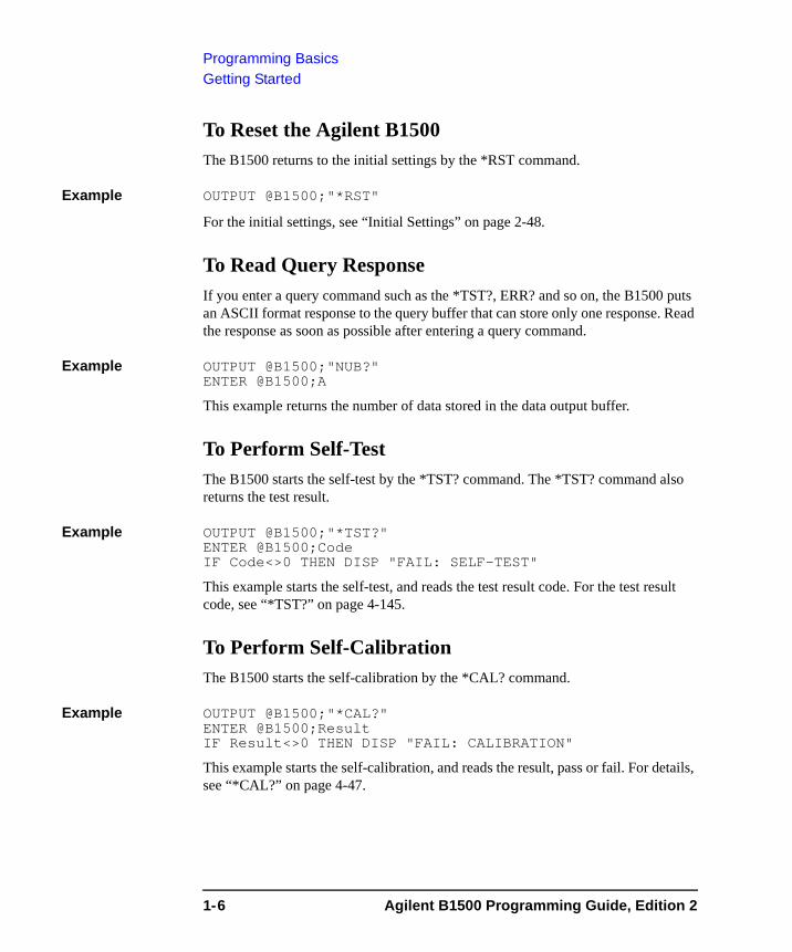
To Reset the Agilent B1500The B1500 returns to the initial settings by the *RST command.
Example OUTPUT @B1500;"*RST"
For the initial settings, see “Initial Settings” on page 2-48.
To Read Query ResponseIf you enter a query command such as the *TST?, ERR? and so on, the B1500 puts an ASCII format response to the query buffer that can store only one response. Read the response as soon as possible after entering a query command.
Example OUTPUT @B1500;"NUB?"ENTER @B1500;A
This example returns the number of data stored in the data output buffer.
To Perform Self-TestThe B1500 starts the self-test by the *TST? command. The *TST? command also returns the test result.
Example OUTPUT @B1500;"*TST?"ENTER @B1500;CodeIF Code<>0 THEN DISP "FAIL: SELF-TEST"
This example starts the self-test, and reads the test result code. For the test result code, see “*TST?” on page 4-145.
To Perform Self-CalibrationThe B1500 starts the self-calibration by the *CAL? command.
Example OUTPUT @B1500;"*CAL?"ENTER @B1500;ResultIF Result<>0 THEN DISP "FAIL: CALIBRATION"
This example starts the self-calibration, and reads the result, pass or fail. For details, see “*CAL?” on page 4-47.
1-6 Agilent B1500 Programming Guide, Edition 2
Programming BasicsGetting Started
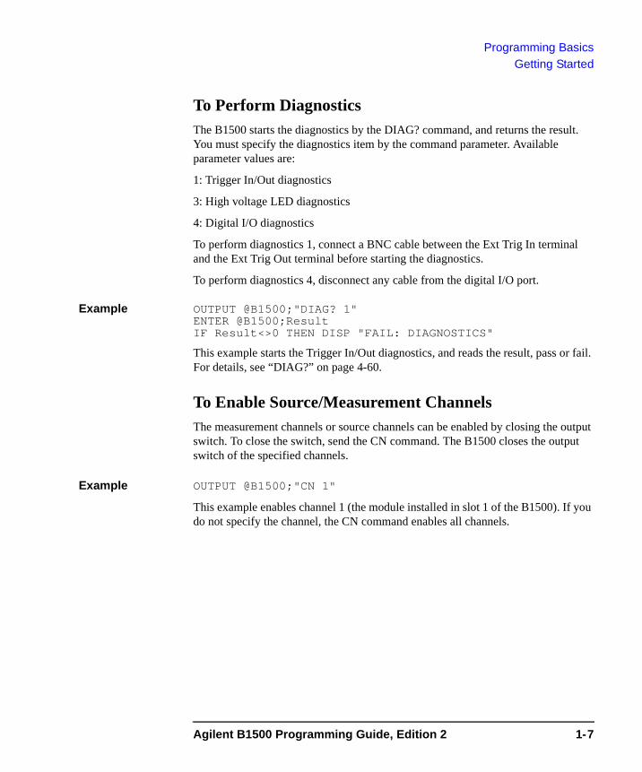
To Perform DiagnosticsThe B1500 starts the diagnostics by the DIAG? command, and returns the result. You must specify the diagnostics item by the command parameter. Available parameter values are:
1: Trigger In/Out diagnostics
3: High voltage LED diagnostics
4: Digital I/O diagnostics
To perform diagnostics 1, connect a BNC cable between the Ext Trig In terminal and the Ext Trig Out terminal before starting the diagnostics.
To perform diagnostics 4, disconnect any cable from the digital I/O port.
Example OUTPUT @B1500;"DIAG? 1"ENTER @B1500;ResultIF Result<>0 THEN DISP "FAIL: DIAGNOSTICS"
This example starts the Trigger In/Out diagnostics, and reads the result, pass or fail. For details, see “DIAG?” on page 4-60.
To Enable Source/Measurement ChannelsThe measurement channels or source channels can be enabled by closing the output switch. To close the switch, send the CN command. The B1500 closes the output switch of the specified channels.
Example OUTPUT @B1500;"CN 1"
This example enables channel 1 (the module installed in slot 1 of the B1500). If you do not specify the channel, the CN command enables all channels.
Agilent B1500 Programming Guide, Edition 2 1-7
Programming BasicsGetting Started
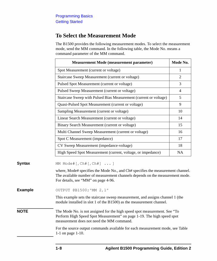
To Select the Measurement ModeThe B1500 provides the following measurement modes. To select the measurement mode, send the MM command. In the following table, the Mode No. means a command parameter of the MM command.
Syntax MM Mode#[,Ch#[,Ch#] ... ]
where, Mode# specifies the Mode No., and Ch# specifies the measurement channel. The available number of measurement channels depends on the measurement mode. For details, see “MM” on page 4-96.
Example OUTPUT @B1500;"MM 2,1"
This example sets the staircase sweep measurement, and assigns channel 1 (the module installed in slot 1 of the B1500) as the measurement channel.
NOTE The Mode No. is not assigned for the high speed spot measurement. See “To Perform High Speed Spot Measurement” on page 1-19. The high speed spot measurement does not need the MM command.
For the source output commands available for each measurement mode, see Table 1-1 on page 1-10.
Measurement Mode (measurement parameter) Mode No.
Spot Measurement (current or voltage) 1
Staircase Sweep Measurement (current or voltage) 2
Pulsed Spot Measurement (current or voltage) 3
Pulsed Sweep Measurement (current or voltage) 4
Staircase Sweep with Pulsed Bias Measurement (current or voltage) 5
Quasi-Pulsed Spot Measurement (current or voltage) 9
Sampling Measurement (current or voltage) 10
Linear Search Measurement (current or voltage) 14
Binary Search Measurement (current or voltage) 15
Multi Channel Sweep Measurement (current or voltage) 16
Spot C Measurement (impedance) 17
CV Sweep Measurement (impedance-voltage) 18
High Speed Spot Measurement (current, voltage, or impedance) NA
1-8 Agilent B1500 Programming Guide, Edition 2
Programming BasicsGetting Started
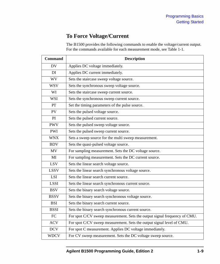
To Force Voltage/CurrentThe B1500 provides the following commands to enable the voltage/current output. For the commands available for each measurement mode, see Table 1-1.
Command Description
DV Applies DC voltage immediately.DI Applies DC current immediately.
WV Sets the staircase sweep voltage source.WSV Sets the synchronous sweep voltage source.WI Sets the staircase sweep current source.
WSI Sets the synchronous sweep current source.PT Set the timing parameters of the pulse source.PV Sets the pulsed voltage source.PI Sets the pulsed current source.
PWV Sets the pulsed sweep voltage source.PWI Sets the pulsed sweep current source.
WNX Sets a sweep source for the multi sweep measurement.BDV Sets the quasi-pulsed voltage source.MV For sampling measurement. Sets the DC voltage source.MI For sampling measurement. Sets the DC current source.
LSV Sets the linear search voltage source.LSSV Sets the linear search synchronous voltage source.LSI Sets the linear search current source.
LSSI Sets the linear search synchronous current source.BSV Sets the binary search voltage source.
BSSV Sets the binary search synchronous voltage source.BSI Sets the binary search current source.
BSSI Sets the binary search synchronous current source.FC For spot C/CV sweep measurement. Sets the output signal frequency of CMU.
ACV For spot C/CV sweep measurement. Sets the output signal level of CMU.DCV For spot C measurement. Applies DC voltage immediately.
WDCV For CV sweep measurement. Sets the DC voltage sweep source.
Agilent B1500 Programming Guide, Edition 2 1-9
Programming BasicsGetting Started
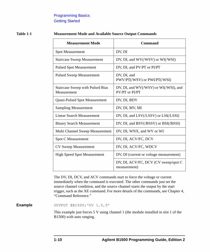
Table 1-1 Measurement Mode and Available Source Output Commands
The DV, DI, DCV, and ACV commands start to force the voltage or current immediately when the command is executed. The other commands just set the source channel condition, and the source channel starts the output by the start trigger, such as the XE command. For more details of the commands, see Chapter 4, “Command Reference.”
Example OUTPUT @B1500;"DV 1,0,5"
This example just forces 5 V using channel 1 (the module installed in slot 1 of the B1500) with auto ranging.
Measurement Mode Command
Spot Measurement DV, DI
Staircase Sweep Measurement DV, DI, and WV(/WSV) or WI(/WSI)
Pulsed Spot Measurement DV, DI, and PV/PT or PI/PT
Pulsed Sweep Measurement DV, DI, and PWV/PT(/WSV) or PWI/PT(/WSI)
Staircase Sweep with Pulsed Bias Measurement
DV, DI, and WV(/WSV) or WI(/WSI), and PV/PT or PI/PT
Quasi-Pulsed Spot Measurement DV, DI, BDV
Sampling Measurement DV, DI, MV, MI
Linear Search Measurement DV, DI, and LSV(/LSSV) or LSI(/LSSI)
Binary Search Measurement DV, DI, and BSV(/BSSV) or BSI(/BSSI)
Multi Channel Sweep Measurement DV, DI, WNX, and WV or WI
Spot C Measurement DV, DI, ACV/FC, DCV
CV Sweep Measurement DV, DI, ACV/FC, WDCV
High Speed Spot Measurement DV, DI (current or voltage measurement)
DV, DI, ACV/FC, DCV (CV sweep/spot C measurement)
1-10 Agilent B1500 Programming Guide, Edition 2
Programming BasicsGetting Started
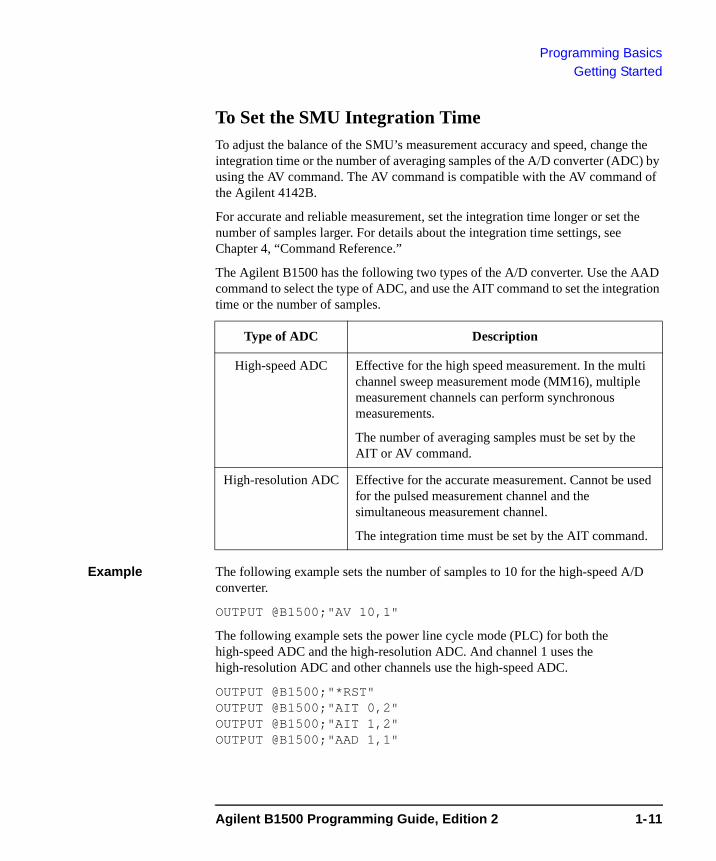
To Set the SMU Integration TimeTo adjust the balance of the SMU’s measurement accuracy and speed, change the integration time or the number of averaging samples of the A/D converter (ADC) by using the AV command. The AV command is compatible with the AV command of the Agilent 4142B.
For accurate and reliable measurement, set the integration time longer or set the number of samples larger. For details about the integration time settings, see Chapter 4, “Command Reference.”
The Agilent B1500 has the following two types of the A/D converter. Use the AAD command to select the type of ADC, and use the AIT command to set the integration time or the number of samples.
Example The following example sets the number of samples to 10 for the high-speed A/D converter.
OUTPUT @B1500;"AV 10,1"
The following example sets the power line cycle mode (PLC) for both the high-speed ADC and the high-resolution ADC. And channel 1 uses the high-resolution ADC and other channels use the high-speed ADC.
OUTPUT @B1500;"*RST"OUTPUT @B1500;"AIT 0,2"OUTPUT @B1500;"AIT 1,2"OUTPUT @B1500;"AAD 1,1"
Type of ADC Description
High-speed ADC Effective for the high speed measurement. In the multi channel sweep measurement mode (MM16), multiple measurement channels can perform synchronous measurements.
The number of averaging samples must be set by the AIT or AV command.
High-resolution ADC Effective for the accurate measurement. Cannot be used for the pulsed measurement channel and the simultaneous measurement channel.
The integration time must be set by the AIT command.
Agilent B1500 Programming Guide, Edition 2 1-11
Programming BasicsGetting Started
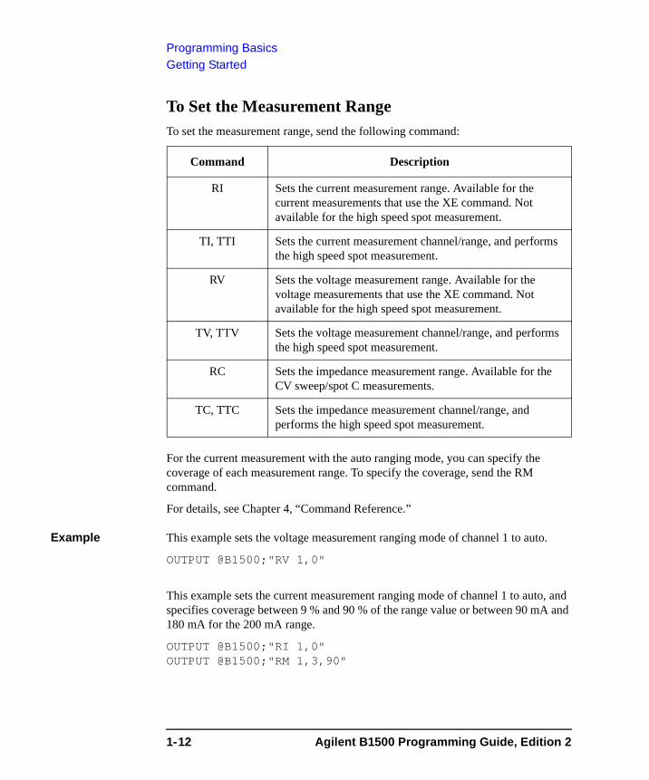
To Set the Measurement RangeTo set the measurement range, send the following command:
For the current measurement with the auto ranging mode, you can specify the coverage of each measurement range. To specify the coverage, send the RM command.
For details, see Chapter 4, “Command Reference.”
Example This example sets the voltage measurement ranging mode of channel 1 to auto.
OUTPUT @B1500;"RV 1,0"
This example sets the current measurement ranging mode of channel 1 to auto, and specifies coverage between 9 % and 90 % of the range value or between 90 mA and 180 mA for the 200 mA range.
OUTPUT @B1500;"RI 1,0"OUTPUT @B1500;"RM 1,3,90"
Command Description
RI Sets the current measurement range. Available for the current measurements that use the XE command. Not available for the high speed spot measurement.
TI, TTI Sets the current measurement channel/range, and performs the high speed spot measurement.
RV Sets the voltage measurement range. Available for the voltage measurements that use the XE command. Not available for the high speed spot measurement.
TV, TTV Sets the voltage measurement channel/range, and performs the high speed spot measurement.
RC Sets the impedance measurement range. Available for the CV sweep/spot C measurements.
TC, TTC Sets the impedance measurement channel/range, and performs the high speed spot measurement.
1-12 Agilent B1500 Programming Guide, Edition 2
Programming BasicsGetting Started
To Pause Command ExecutionTo pause command execution until the specified wait time elapses, send the PA command.
Example OUTPUT @B1500;"PA 5"
If this command is sent, the B1500 waits 5 seconds before executing the next command.
To Start MeasurementTo start measurement other than the high speed spot measurement, send the XE command.
Example OUTPUT @B1500;"XE"
This starts the measurement specified by the MM command.
For the high speed spot measurement, see “To Perform High Speed Spot Measurement” on page 1-19.
To Force 0 VTo force 0 V immediately, send the DZ command. The B1500 memorizes the present source output settings of the specified channel, and changes the specified channel output to 0 V. If you do not specify the channel, the DZ command function is effective for all channels.
Example OUTPUT @B1500;"DZ 1"
If this command is sent, the B1500 memorizes the current settings of channel 1 (the module installed in slot 1 of the B1500), and changes channel 1 output to 0 V.
To restore the settings stored by the DZ command, send the RZ command. For details, see Chapter 4, “Command Reference.”
Agilent B1500 Programming Guide, Edition 2 1-13
Programming BasicsGetting Started
To Disable Source/Measurement ChannelsTo disable the channels, send the CL command. The B1500 opens the output switch of the specified channels. Opening the output switch disables the channel.
Example OUTPUT @B1500;"CL 1"
This example disables channel 1 (the module installed in slot 1 of the B1500). If you do not specify the channel, the CL command disables all channels.
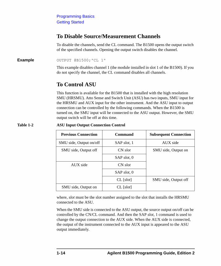
To Control ASUThis function is available for the B1500 that is installed with the high resolution SMU (HRSMU). Atto Sense and Switch Unit (ASU) has two inputs, SMU input for the HRSMU and AUX input for the other instrument. And the ASU input to output connection can be controlled by the following commands. When the B1500 is turned on, the SMU input will be connected to the ASU output. However, the SMU output switch will be off at this time.
Table 1-2 ASU Input Output Connection Control
where, slot must be the slot number assigned to the slot that installs the HRSMU connected to the ASU.
When the SMU side is connected to the ASU output, the source output on/off can be controlled by the CN/CL command. And then the SAP slot, 1 command is used to change the output connection to the AUX side. When the AUX side is connected, the output of the instrument connected to the AUX input is appeared to the ASU output immediately.
Previous Connection Command Subsequent Connection
SMU side, Output on/off SAP slot, 1 AUX side
SMU side, Output off CN slot SMU side, Output on
SAP slot, 0
AUX side CN slot
SAP slot, 0
CL [slot] SMU side, Output off
SMU side, Output on CL [slot]
1-14 Agilent B1500 Programming Guide, Edition 2
Programming BasicsGetting Started
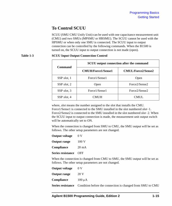
To Control SCUUSCUU (SMU CMU Unify Unit) can be used with one capacitance measurement unit (CMU) and two SMUs (MPSMU or HRSMU). The SCUU cannot be used with the HPSMU or when only one SMU is connected. The SCUU input to output connection can be controlled by the following commands. When the B1500 is turned on, the SCUU input to output connection is not made (open).
Table 1-3 SCUU Input Output Connection Control
where, slot means the number assigned to the slot that installs the CMU. Force1/Sense1 is connected to the SMU installed in the slot numbered slot-1. Force2/Sense2 is connected to the SMU installed in the slot numbered slot-2. When the SCUU input to output connection is made, the measurement unit output switch will be automatically set to ON.
When the connection is changed from SMU to CMU, the SMU output will be set as follows. The other setup parameters are not changed.
Output voltage 0 V
Output range 100 V
Compliance 20 mA
Series resistance OFF
When the connection is changed from CMU to SMU, the SMU output will be set as follows. The other setup parameters are not changed.
Output voltage 0 V
Output range 20 V
Compliance 100 μA
Series resistance Condition before the connection is changed from SMU to CMU
CommandSCUU output connection after the command
CMUH/Force1/Sense1 CMUL/Force2/Sense2
SSP slot, 1 Force1/Sense1 Open
SSP slot, 2 Open Force2/Sense2
SSP slot, 3 Force1/Sense1 Force2/Sense2
SSP slot, 4 CMUH CMUL
Agilent B1500 Programming Guide, Edition 2 1-15

Programming BasicsGetting Started
To Read Error Code/MessageIf any error occurs, the B1500 will not put the measurement data into the data output buffer. Hence, confirm that no error has occurred before reading the measurement data. To read the error code, enter the ERR? command, and to read the error message, enter the EMG? command.
Example OUTPUT @B1500;"ERR? 1"ENTER @B1500;CodeIF Code<>0 THEN
OUTPUT @B1500;"EMG? ";CodeENTER @B1500;Msg$
PRINT "ERROR: ";Msg$ELSE: :
This example checks the error buffer, and prints the error message on the computer screen if any error code is stored in the error buffer.
To Read Spot Measurement DataAfter the spot measurements, the B1500 puts the measurement data into its output data buffer. You can read the data as shown below. For the data output format, see “Data Output Format” on page 1-23.
Example 1 For the HP BASIC users, use the ENTER statement. The example stores the header information and the measurement data included in the ASCII data set by the FMT5 command into the Head$ and Mdata variables respectively.
ENTER @B1500 USING "#,3A,12D,X";Head$,Mdata
Example 2 For the Microsoft Visual Basic .NET with Agilent T&M Programmer’s Toolkit users, use the Read, ReadList, UnbufferedRead methods and so on. The example stores the header information and the measurement data included in the ASCII data set by the FMT5 command into the head and mdata variables respectively.
ret_value = B1500.Read(True)head = Left(ret_val, 3)mdata = Val(Right(ret_val, 12))
1-16 Agilent B1500 Programming Guide, Edition 2
Programming BasicsGetting Started
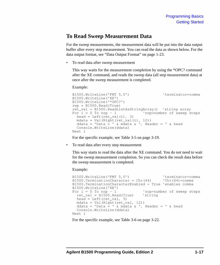
To Read Sweep Measurement DataFor the sweep measurements, the measurement data will be put into the data output buffer after every step measurement. You can read the data as shown below. For the data output format, see “Data Output Format” on page 1-23.
• To read data after sweep measurement
This way waits for the measurement completion by using the *OPC? command after the XE command, and reads the sweep data (all step measurement data) at once after the sweep measurement is completed.
Example:
B1500.WriteLine("FMT 5,0") ’terminator=commaB1500.WriteLine("XE")B1500.WriteLine("*OPC?")rep = B1500.Read(True)ret_val = B1500.ReadListAsStringArray() ’string arrayFor i = 0 To nop - 1 ’nop=number of sweep steps
head = Left(ret_val(i), 3)mdata = Val(Right(ret_val(i), 12))ddata = "Data = " & mdata & ", Header = " & headConsole.WriteLine(ddata)
Next i
For the specific example, see Table 3-5 on page 3-19.
• To read data after every step measurement
This way starts to read the data after the XE command. You do not need to wait for the sweep measurement completion. So you can check the result data before the sweep measurement is completed.
Example:
B1500.WriteLine("FMT 5,0") ’terminator=commaB1500.TerminationCharacter = Chr(44) ’Chr(44)=commaB1500.TerminationCharacterEnabled = True ’enables commaB1500.WriteLine("XE")For i = 0 To nop - 1 ’nop=number of sweep steps
ret_val = B1500.Read(True) ’stringhead = Left(ret_val, 3)mdata = Val(Right(ret_val, 12))ddata = "Data = " & mdata & ", Header = " & headConsole.WriteLine(ddata)
Next i
For the specific example, see Table 3-6 on page 3-22.
Agilent B1500 Programming Guide, Edition 2 1-17
Programming BasicsGetting Started
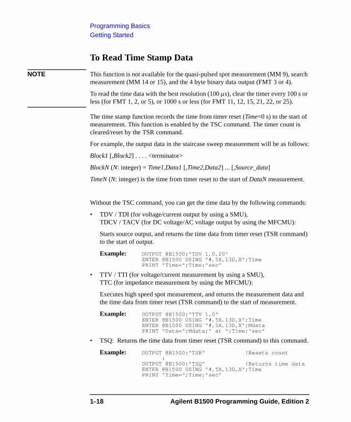
To Read Time Stamp Data
NOTE This function is not available for the quasi-pulsed spot measurement (MM 9), search measurement (MM 14 or 15), and the 4 byte binary data output (FMT 3 or 4).
To read the time data with the best resolution (100 μs), clear the timer every 100 s or less (for FMT 1, 2, or 5), or 1000 s or less (for FMT 11, 12, 15, 21, 22, or 25).
The time stamp function records the time from timer reset (Time=0 s) to the start of measurement. This function is enabled by the TSC command. The timer count is cleared/reset by the TSR command.
For example, the output data in the staircase sweep measurement will be as follows:
Block1 [,Block2] . . . . <terminator>
BlockN (N: integer) = Time1,Data1 [,Time2,Data2] ... [,Source_data]
TimeN (N: integer) is the time from timer reset to the start of DataN measurement.
Without the TSC command, you can get the time data by the following commands:
• TDV / TDI (for voltage/current output by using a SMU),TDCV / TACV (for DC voltage/AC voltage output by using the MFCMU):
Starts source output, and returns the time data from timer reset (TSR command) to the start of output.
Example: OUTPUT @B1500;"TDV 1,0,20"ENTER @B1500 USING "#,5X,13D,X";TimePRINT "Time=";Time;"sec"
• TTV / TTI (for voltage/current measurement by using a SMU),TTC (for impedance measurement by using the MFCMU):
Executes high speed spot measurement, and returns the measurement data and the time data from timer reset (TSR command) to the start of measurement.
Example: OUTPUT @B1500;"TTV 1,0"ENTER @B1500 USING "#,5X,13D,X";TimeENTER @B1500 USING "#,5X,13D,X";MdataPRINT "Data=";Mdata;" at ";Time;"sec"
• TSQ: Returns the time data from timer reset (TSR command) to this command.
Example: OUTPUT @B1500;"TSR" !Resets count:
OUTPUT @B1500;"TSQ" !Returns time dataENTER @B1500 USING "#,5X,13D,X";TimePRINT "Time=";Time;"sec"
1-18 Agilent B1500 Programming Guide, Edition 2

Programming BasicsGetting Started
To Perform High Speed Spot MeasurementThe high speed spot measurement does not need the MM and XE commands to set the measurement mode and start measurement. To start and perform the high speed spot measurement immediately, send the TI command for current measurement, the TV command for voltage measurement, or the TC command for impedance measurement. The following example program measures current by using the TI command, and displays the measurement result data on the computer screen.
Example 10 ASSIGN @B1500 TO 71720 OUTPUT @B1500;"*RST"30 OUTPUT @B1500;"FMT 5"40 OUTPUT @B1500;"CN 1,2,3,4"50 OUTPUT @B1500;"DV 1,0,0"60 OUTPUT @B1500;"DV 2,0,0"70 OUTPUT @B1500;"DV 3,0,2"80 OUTPUT @B1500;"DV 4,0,5"90 OUTPUT @B1500;"TI 4,0"100 ENTER @B1500 USING "#,3A,12D,X";Head$,Data110 PRINT Head$,Data120 OUTPUT @B1500;"DZ"130 OUTPUT @B1500;"CL"140 END
Line Number Description
10 Assigns the I/O path to control the B1500.
20 Initializes the B1500.
30 Sets the data output format (ASCII with header and <,>).
40 Enables channels 1, 2, 3, and 4.
50 to 80 Forces the DC voltage. Channel 1 and 2 force 0 V, channel 3 forces 2 V, and channel 4 forces 5 V with auto ranging.
90 Performs the high speed spot measurement using channel 4 with auto ranging.
100 to 110 Prints the header data and measurement data on the screen.
120 Forces 0 V. All channels force 0 V.
130 Disables all channels.
Agilent B1500 Programming Guide, Edition 2 1-19
Programming BasicsCommand Input Format
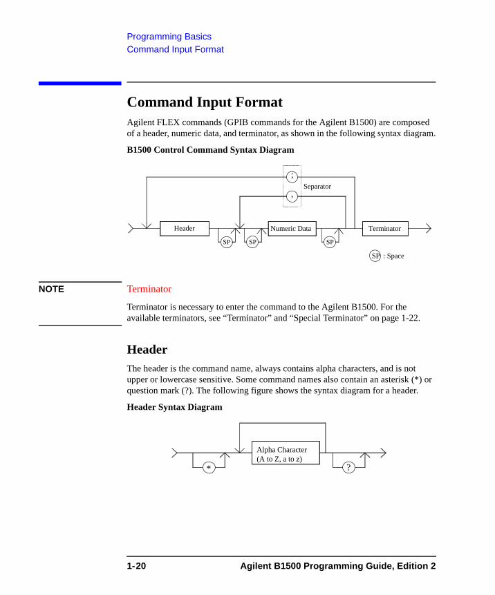
Command Input Format Agilent FLEX commands (GPIB commands for the Agilent B1500) are composed of a header, numeric data, and terminator, as shown in the following syntax diagram.
B1500 Control Command Syntax Diagram
NOTE Terminator
Terminator is necessary to enter the command to the Agilent B1500. For the available terminators, see “Terminator” and “Special Terminator” on page 1-22.
HeaderThe header is the command name, always contains alpha characters, and is not upper or lowercase sensitive. Some command names also contain an asterisk (*) or question mark (?). The following figure shows the syntax diagram for a header.
Header Syntax Diagram
Header Numeric Data Terminator
,
SP : Space
;Separator
SP SP SP
Alpha Character(A to Z, a to z)
* ?
1-20 Agilent B1500 Programming Guide, Edition 2
Programming BasicsCommand Input Format
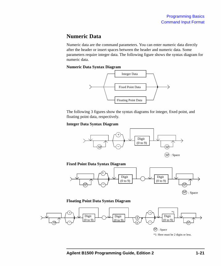
Numeric DataNumeric data are the command parameters. You can enter numeric data directly after the header or insert spaces between the header and numeric data. Some parameters require integer data. The following figure shows the syntax diagram for numeric data.
Numeric Data Syntax Diagram
The following 3 figures show the syntax diagrams for integer, fixed point, and floating point data, respectively.
Integer Data Syntax Diagram
Fixed Point Data Syntax Diagram
Floating Point Data Syntax Diagram
Fixed Point Data
Integer Data
Floating Point Data
Digit(0 to 9)
− SP
SP : Space
SP
+
Digit(0 to 9)
− SP
SP : Space
SP
+ Digit(0 to 9)
Digit(0 to 9)
− SP
SP : Space
SP
+ Digit(0 to 9)
−
+
eE Digit
(0 to 9)
*1
*1: Here must be 2 digits or less.
Agilent B1500 Programming Guide, Edition 2 1-21
Programming BasicsCommand Input Format
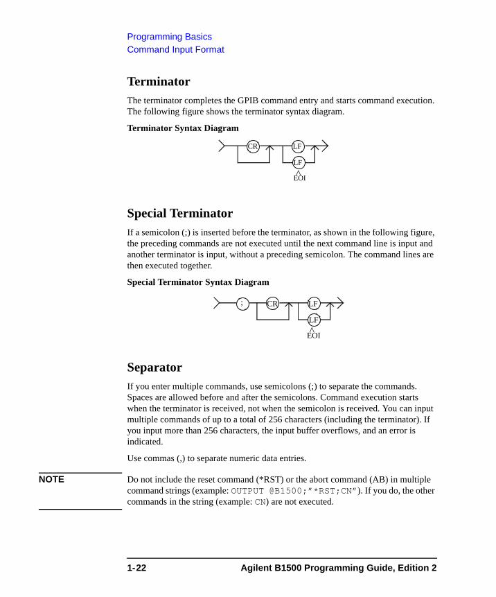
TerminatorThe terminator completes the GPIB command entry and starts command execution. The following figure shows the terminator syntax diagram.
Terminator Syntax Diagram
Special TerminatorIf a semicolon (;) is inserted before the terminator, as shown in the following figure, the preceding commands are not executed until the next command line is input and another terminator is input, without a preceding semicolon. The command lines are then executed together.
Special Terminator Syntax Diagram
SeparatorIf you enter multiple commands, use semicolons (;) to separate the commands. Spaces are allowed before and after the semicolons. Command execution starts when the terminator is received, not when the semicolon is received. You can input multiple commands of up to a total of 256 characters (including the terminator). If you input more than 256 characters, the input buffer overflows, and an error is indicated.
Use commas (,) to separate numeric data entries.
NOTE Do not include the reset command (*RST) or the abort command (AB) in multiple command strings (example: OUTPUT @B1500;”*RST;CN”). If you do, the other commands in the string (example: CN) are not executed.
CR
EOI
LF
LF
^
CR
EOI
LF
LF
^
;
1-22 Agilent B1500 Programming Guide, Edition 2
Programming BasicsData Output Format
Data Output FormatAgilent B1500 provides the following data output formats:
• “ASCII Data Output Format”
The B1500 supports the ASCII data format that is the common format for the instruments that support the Agilent FLEX command mode.
• “Binary Data Output Format”
The B1500 supports the 4 bytes binary data format that is the common format for the instruments that support the Agilent FLEX command mode. The B1500 also supports the dedicated 8 bytes binary format. The binary format enables faster data transfer time than ASCII format. You need to calculate the data to get the measurement result.
To select the data output format, use the FMT command. See “FMT” on page 4-70.
For the query response, the returned data is always stored in the query buffer in ASCII format, regardless of the FMT command setting.
A minimum of 17×1001×2 (34034) measurement data can be stored in the data output buffer.
ConventionsThe following conventions are used in this section.
Data Output data that the B1500 sends after a measurement.
[Data] Optional output data sent when there are multiple output data items.
For example, source data will be sent with measurement data after the staircase sweep measurements when the source data output is enabled by the FMT command.
<terminator> Terminator.
<CR/LF^EOI> (two bytes) or <,> (one byte) for ASCII data.
<CR/LF^EOI> (two bytes) or <^EOI> (0 byte) for binary data.
You can select by using the FMT command.
Agilent B1500 Programming Guide, Edition 2 1-23
Programming BasicsData Output Format
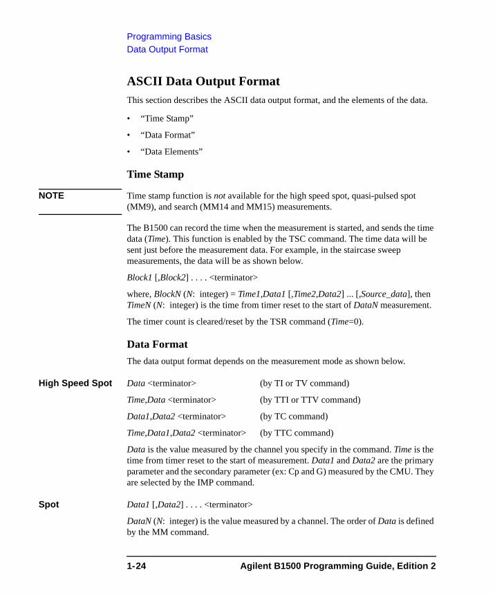
ASCII Data Output FormatThis section describes the ASCII data output format, and the elements of the data.
• “Time Stamp”
• “Data Format”
• “Data Elements”
Time Stamp
NOTE Time stamp function is not available for the high speed spot, quasi-pulsed spot (MM9), and search (MM14 and MM15) measurements.
The B1500 can record the time when the measurement is started, and sends the time data (Time). This function is enabled by the TSC command. The time data will be sent just before the measurement data. For example, in the staircase sweep measurements, the data will be as shown below.
Block1 [,Block2] . . . . <terminator>
where, BlockN (N: integer) = Time1,Data1 [,Time2,Data2] ... [,Source_data], then TimeN (N: integer) is the time from timer reset to the start of DataN measurement.
The timer count is cleared/reset by the TSR command (Time=0).
Data FormatThe data output format depends on the measurement mode as shown below.
High Speed Spot Data <terminator> (by TI or TV command)
Time,Data <terminator> (by TTI or TTV command)
Data1,Data2 <terminator> (by TC command)
Time,Data1,Data2 <terminator> (by TTC command)
Data is the value measured by the channel you specify in the command. Time is the time from timer reset to the start of measurement. Data1 and Data2 are the primary parameter and the secondary parameter (ex: Cp and G) measured by the CMU. They are selected by the IMP command.
Spot Data1 [,Data2] . . . . <terminator>
DataN (N: integer) is the value measured by a channel. The order of Data is defined by the MM command.
1-24 Agilent B1500 Programming Guide, Edition 2
Programming BasicsData Output Format
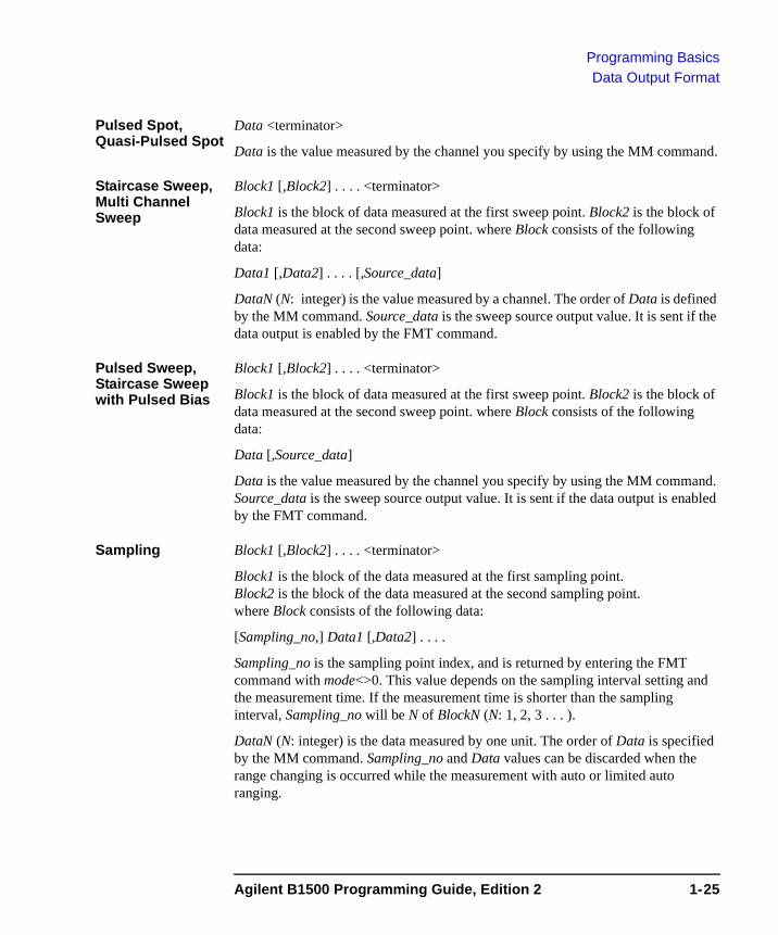
Pulsed Spot, Quasi-Pulsed Spot
Data <terminator>
Data is the value measured by the channel you specify by using the MM command.
Staircase Sweep, Multi Channel Sweep
Block1 [,Block2] . . . . <terminator>
Block1 is the block of data measured at the first sweep point. Block2 is the block of data measured at the second sweep point. where Block consists of the following data:
Data1 [,Data2] . . . . [,Source_data]
DataN (N: integer) is the value measured by a channel. The order of Data is defined by the MM command. Source_data is the sweep source output value. It is sent if the data output is enabled by the FMT command.
Pulsed Sweep, Staircase Sweep with Pulsed Bias
Block1 [,Block2] . . . . <terminator>
Block1 is the block of data measured at the first sweep point. Block2 is the block of data measured at the second sweep point. where Block consists of the following data:
Data [,Source_data]
Data is the value measured by the channel you specify by using the MM command. Source_data is the sweep source output value. It is sent if the data output is enabled by the FMT command.
Sampling Block1 [,Block2] . . . . <terminator>
Block1 is the block of the data measured at the first sampling point. Block2 is the block of the data measured at the second sampling point. where Block consists of the following data:
[Sampling_no,] Data1 [,Data2] . . . .
Sampling_no is the sampling point index, and is returned by entering the FMT command with mode<>0. This value depends on the sampling interval setting and the measurement time. If the measurement time is shorter than the sampling interval, Sampling_no will be N of BlockN (N: 1, 2, 3 . . . ).
DataN (N: integer) is the data measured by one unit. The order of Data is specified by the MM command. Sampling_no and Data values can be discarded when the range changing is occurred while the measurement with auto or limited auto ranging.
Agilent B1500 Programming Guide, Edition 2 1-25
Programming BasicsData Output Format
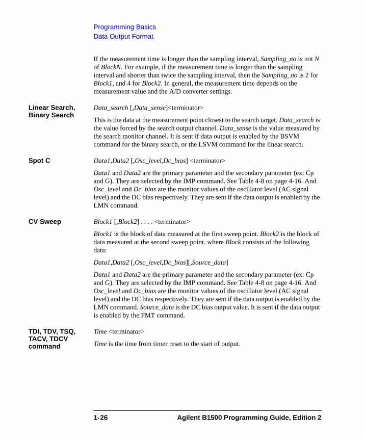
If the measurement time is longer than the sampling interval, Sampling_no is not N of BlockN. For example, if the measurement time is longer than the sampling interval and shorter than twice the sampling interval, then the Sampling_no is 2 for Block1, and 4 for Block2. In general, the measurement time depends on the measurement value and the A/D converter settings.
Linear Search, Binary Search
Data_search [,Data_sense]<terminator>
This is the data at the measurement point closest to the search target. Data_search is the value forced by the search output channel. Data_sense is the value measured by the search monitor channel. It is sent if data output is enabled by the BSVM command for the binary search, or the LSVM command for the linear search.
Spot C Data1,Data2 [,Osc_level,Dc_bias] <terminator>
Data1 and Data2 are the primary parameter and the secondary parameter (ex: Cp and G). They are selected by the IMP command. See Table 4-8 on page 4-16. And Osc_level and Dc_bias are the monitor values of the oscillator level (AC signal level) and the DC bias respectively. They are sent if the data output is enabled by the LMN command.
CV Sweep Block1 [,Block2] . . . . <terminator>
Block1 is the block of data measured at the first sweep point. Block2 is the block of data measured at the second sweep point. where Block consists of the following data:
Data1,Data2 [,Osc_level,Dc_bias][,Source_data]
Data1 and Data2 are the primary parameter and the secondary parameter (ex: Cp and G). They are selected by the IMP command. See Table 4-8 on page 4-16. And Osc_level and Dc_bias are the monitor values of the oscillator level (AC signal level) and the DC bias respectively. They are sent if the data output is enabled by the LMN command. Source_data is the DC bias output value. It is sent if the data output is enabled by the FMT command.
TDI, TDV, TSQ, TACV, TDCV command
Time <terminator>
Time is the time from timer reset to the start of output.
1-26 Agilent B1500 Programming Guide, Edition 2
Programming BasicsData Output Format
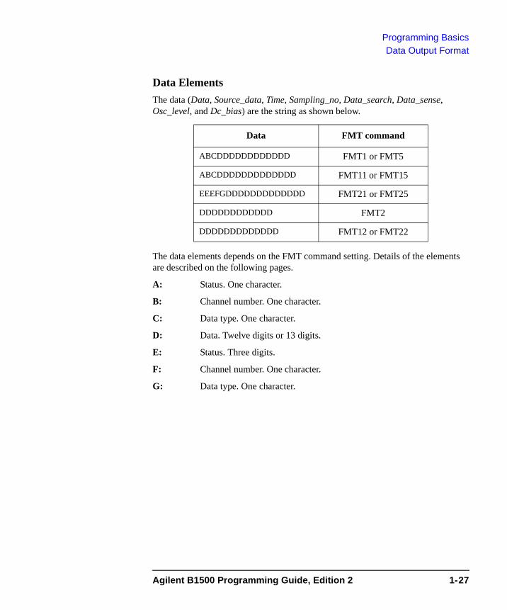
Data ElementsThe data (Data, Source_data, Time, Sampling_no, Data_search, Data_sense, Osc_level, and Dc_bias) are the string as shown below.
The data elements depends on the FMT command setting. Details of the elements are described on the following pages.
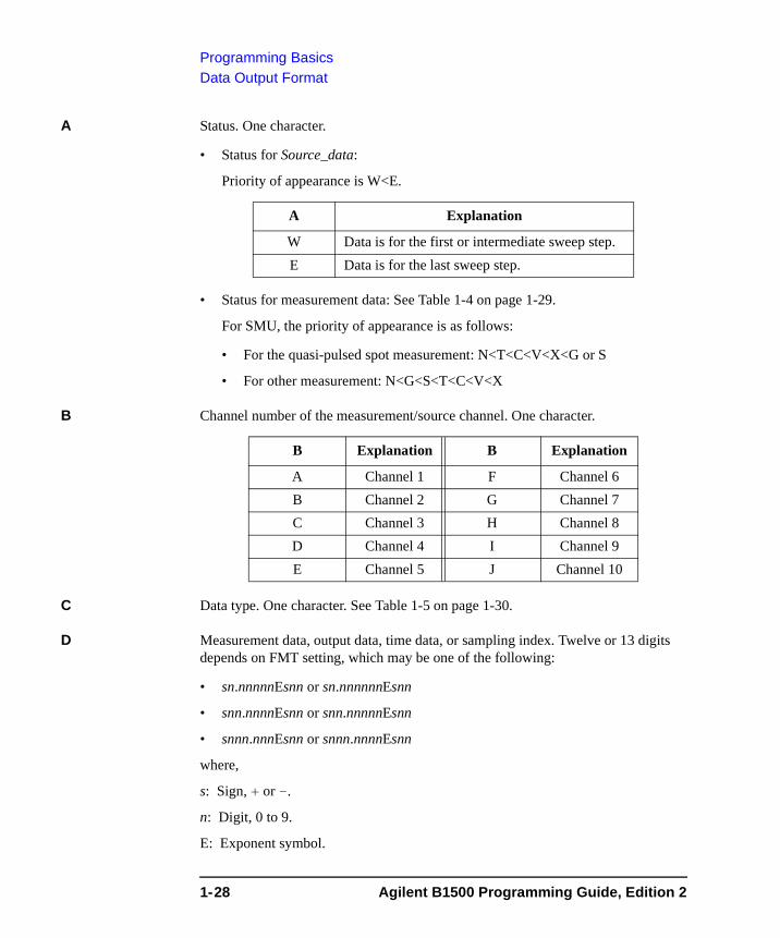
A: Status. One character.
B: Channel number. One character.
C: Data type. One character.
D: Data. Twelve digits or 13 digits.
E: Status. Three digits.
F: Channel number. One character.
G: Data type. One character.
Data FMT command
ABCDDDDDDDDDDDD FMT1 or FMT5
ABCDDDDDDDDDDDDD FMT11 or FMT15
EEEFGDDDDDDDDDDDDD FMT21 or FMT25
DDDDDDDDDDDD FMT2
DDDDDDDDDDDDD FMT12 or FMT22
Agilent B1500 Programming Guide, Edition 2 1-27
Programming BasicsData Output Format
A Status. One character.
• Status for Source_data:
Priority of appearance is W<E.
• Status for measurement data: See Table 1-4 on page 1-29.
For SMU, the priority of appearance is as follows:
• For the quasi-pulsed spot measurement: N<T<C<V<X<G or S
• For other measurement: N<G<S<T<C<V<X
B Channel number of the measurement/source channel. One character.
C Data type. One character. See Table 1-5 on page 1-30.
D Measurement data, output data, time data, or sampling index. Twelve or 13 digits depends on FMT setting, which may be one of the following:
• sn.nnnnnEsnn or sn.nnnnnnEsnn
• snn.nnnnEsnn or snn.nnnnnEsnn
• snnn.nnnEsnn or snnn.nnnnEsnn
where,
s: Sign, + or -.
n: Digit, 0 to 9.
E: Exponent symbol.
A Explanation
W Data is for the first or intermediate sweep step.E Data is for the last sweep step.
B Explanation B Explanation
A Channel 1 F Channel 6B Channel 2 G Channel 7C Channel 3 H Channel 8D Channel 4 I Channel 9E Channel 5 J Channel 10
1-28 Agilent B1500 Programming Guide, Edition 2
Programming BasicsData Output Format
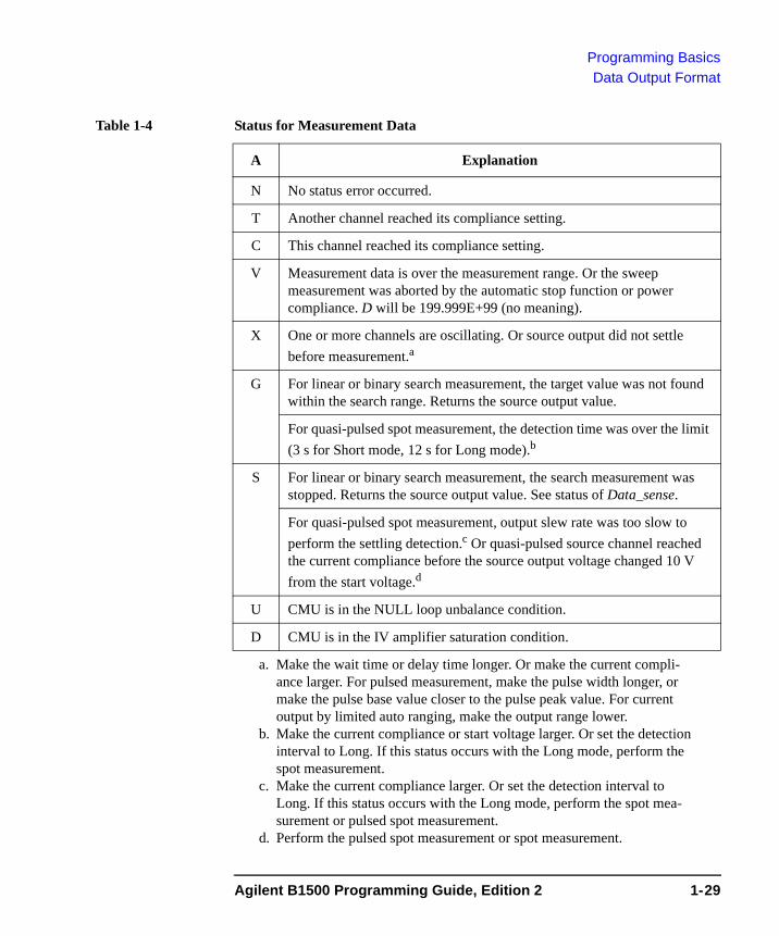
Table 1-4 Status for Measurement Data
A Explanation
N No status error occurred.
T Another channel reached its compliance setting.
C This channel reached its compliance setting.
V Measurement data is over the measurement range. Or the sweep measurement was aborted by the automatic stop function or power compliance. D will be 199.999E+99 (no meaning).
X One or more channels are oscillating. Or source output did not settle before measurement.a
a. Make the wait time or delay time longer. Or make the current compli-ance larger. For pulsed measurement, make the pulse width longer, or make the pulse base value closer to the pulse peak value. For current output by limited auto ranging, make the output range lower.
G For linear or binary search measurement, the target value was not found within the search range. Returns the source output value.
For quasi-pulsed spot measurement, the detection time was over the limit (3 s for Short mode, 12 s for Long mode).b
b. Make the current compliance or start voltage larger. Or set the detection interval to Long. If this status occurs with the Long mode, perform the spot measurement.
S For linear or binary search measurement, the search measurement was stopped. Returns the source output value. See status of Data_sense.
For quasi-pulsed spot measurement, output slew rate was too slow to perform the settling detection.c Or quasi-pulsed source channel reached the current compliance before the source output voltage changed 10 V from the start voltage.d
c. Make the current compliance larger. Or set the detection interval to Long. If this status occurs with the Long mode, perform the spot mea-surement or pulsed spot measurement.
d. Perform the pulsed spot measurement or spot measurement.
U CMU is in the NULL loop unbalance condition.
D CMU is in the IV amplifier saturation condition.
Agilent B1500 Programming Guide, Edition 2 1-29
Programming BasicsData Output Format
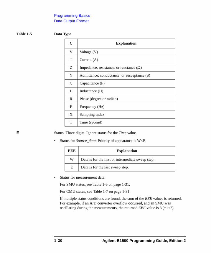
Table 1-5 Data Type
E Status. Three digits. Ignore status for the Time value.
• Status for Source_data: Priority of appearance is W<E.
• Status for measurement data:
For SMU status, see Table 1-6 on page 1-31.
For CMU status, see Table 1-7 on page 1-31.
If multiple status conditions are found, the sum of the EEE values is returned. For example, if an A/D converter overflow occurred, and an SMU was oscillating during the measurements, the returned EEE value is 3 (=1+2).
C Explanation
V Voltage (V)
I Current (A)
Z Impedance, resistance, or reactance (Ω)
Y Admittance, conductance, or susceptance (S)
C Capacitance (F)
L Inductance (H)
R Phase (degree or radian)
F Frequency (Hz)
X Sampling index
T Time (second)
EEE Explanation
W Data is for the first or intermediate sweep step.
E Data is for the last sweep step.
1-30 Agilent B1500 Programming Guide, Edition 2
Programming BasicsData Output Format
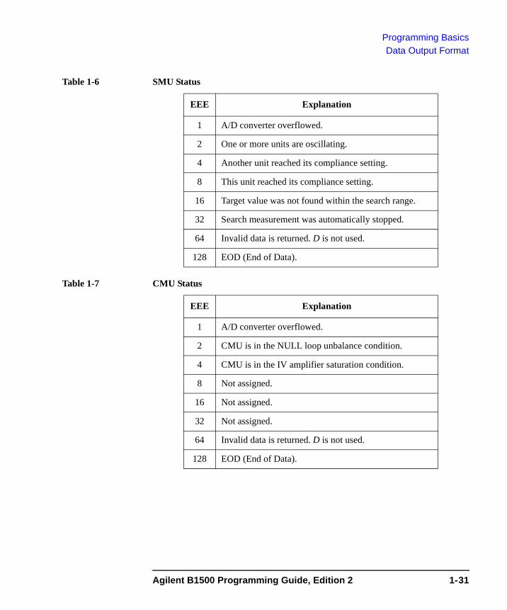
Table 1-6 SMU Status
Table 1-7 CMU Status
EEE Explanation
1 A/D converter overflowed.
2 One or more units are oscillating.
4 Another unit reached its compliance setting.
8 This unit reached its compliance setting.
16 Target value was not found within the search range.
32 Search measurement was automatically stopped.
64 Invalid data is returned. D is not used.
128 EOD (End of Data).
EEE Explanation
1 A/D converter overflowed.
2 CMU is in the NULL loop unbalance condition.
4 CMU is in the IV amplifier saturation condition.
8 Not assigned.
16 Not assigned.
32 Not assigned.
64 Invalid data is returned. D is not used.
128 EOD (End of Data).
Agilent B1500 Programming Guide, Edition 2 1-31
Programming BasicsData Output Format
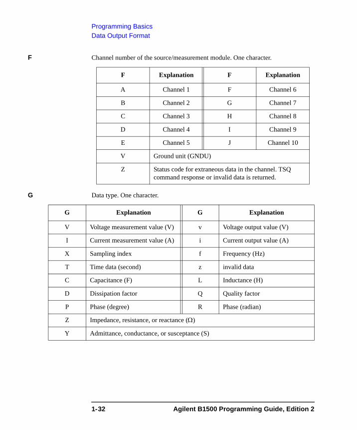
F Channel number of the source/measurement module. One character.
G Data type. One character.
F Explanation F Explanation
A Channel 1 F Channel 6
B Channel 2 G Channel 7
C Channel 3 H Channel 8
D Channel 4 I Channel 9
E Channel 5 J Channel 10
V Ground unit (GNDU)
Z Status code for extraneous data in the channel. TSQ command response or invalid data is returned.
G Explanation G Explanation
V Voltage measurement value (V) v Voltage output value (V)
I Current measurement value (A) i Current output value (A)
X Sampling index f Frequency (Hz)
T Time data (second) z invalid data
C Capacitance (F) L Inductance (H)
D Dissipation factor Q Quality factor
P Phase (degree) R Phase (radian)
Z Impedance, resistance, or reactance (Ω)
Y Admittance, conductance, or susceptance (S)
1-32 Agilent B1500 Programming Guide, Edition 2
Programming BasicsData Output Format
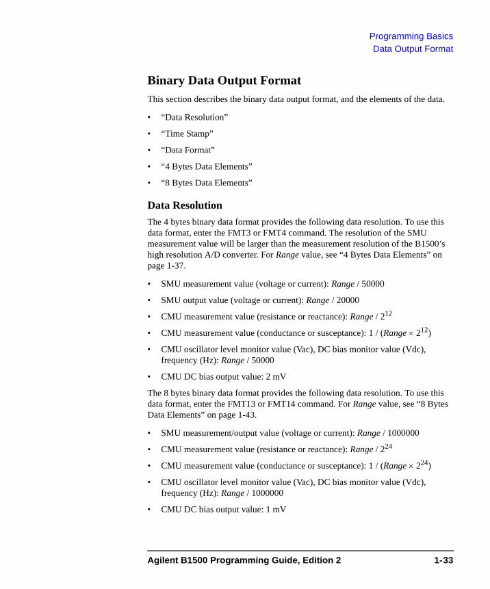
Binary Data Output FormatThis section describes the binary data output format, and the elements of the data.
• “Data Resolution”
• “Time Stamp”
• “Data Format”
• “4 Bytes Data Elements”
• “8 Bytes Data Elements”
Data ResolutionThe 4 bytes binary data format provides the following data resolution. To use this data format, enter the FMT3 or FMT4 command. The resolution of the SMU measurement value will be larger than the measurement resolution of the B1500’s high resolution A/D converter. For Range value, see “4 Bytes Data Elements” on page 1-37.
• SMU measurement value (voltage or current): Range / 50000
• SMU output value (voltage or current): Range / 20000
• CMU measurement value (resistance or reactance): Range / 212
• CMU measurement value (conductance or susceptance): 1 / (Range × 212)
• CMU oscillator level monitor value (Vac), DC bias monitor value (Vdc), frequency (Hz): Range / 50000
• CMU DC bias output value: 2 mV
The 8 bytes binary data format provides the following data resolution. To use this data format, enter the FMT13 or FMT14 command. For Range value, see “8 Bytes Data Elements” on page 1-43.
• SMU measurement/output value (voltage or current): Range / 1000000
• CMU measurement value (resistance or reactance): Range / 224
• CMU measurement value (conductance or susceptance): 1 / (Range × 224)
• CMU oscillator level monitor value (Vac), DC bias monitor value (Vdc), frequency (Hz): Range / 1000000
• CMU DC bias output value: 1 mV
Agilent B1500 Programming Guide, Edition 2 1-33

Programming BasicsData Output Format
Time Stamp
NOTE Time stamp function is not available for the 4 bytes binary data format (FMT3 or FMT4), the high speed spot, quasi-pulsed spot (MM9), and search (MM14 and MM15) measurements.
The B1500 can record the time when the measurement is started, and sends the time data (Time). This function is enabled by the TSC command. The time data will be sent just before the measurement data. For example, in the staircase sweep measurements, the data will be as shown below.
Block1 [Block2] . . . . <terminator>
where, BlockN (N: integer) = Time1 Data1 [Time2 Data2] ... [Source_data], then TimeN (N: integer) is the time from timer reset to the start of DataN measurement.
The timer count is cleared/reset by the TSR command (Time=0).
Data FormatThe data output format depends on the measurement mode as shown below.
High Speed Spot Data <terminator> (by TI or TV command)
Time Data <terminator> (by TTI or TTV command)
Data1 Data2 <terminator> (by TC command)
Time Data1 Data2 <terminator> (by TTC command)
Data is the value measured by the channel you specify in the command. Time is the time from timer reset to the start of measurement. Data1 and Data2 are R (Ω) and X (Ω), or G (S) and B (S) respectively measured by the CMU. They will be automatically selected by the B1500, and will be a couple without data overflow.
Time is available for the 8 bytes binary data format (FMT13 or FMT14) and not available for the 4 bytes binary data format (FMT3 or FMT4)
Spot Data1 [Data2] . . . . <terminator>
DataN (N: integer) is the value measured by a channel. The order of Data is defined by the MM command.
Pulsed Spot, Quasi-Pulsed Spot
Data <terminator>
Data is the value measured by the channel you specify by using the MM command.
1-34 Agilent B1500 Programming Guide, Edition 2
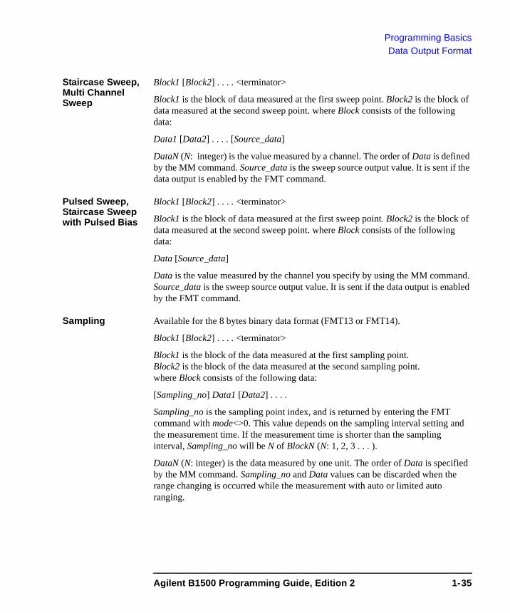
Programming BasicsData Output Format
Staircase Sweep, Multi Channel Sweep
Block1 [Block2] . . . . <terminator>
Block1 is the block of data measured at the first sweep point. Block2 is the block of data measured at the second sweep point. where Block consists of the following data:
Data1 [Data2] . . . . [Source_data]
DataN (N: integer) is the value measured by a channel. The order of Data is defined by the MM command. Source_data is the sweep source output value. It is sent if the data output is enabled by the FMT command.
Pulsed Sweep, Staircase Sweep with Pulsed Bias
Block1 [Block2] . . . . <terminator>
Block1 is the block of data measured at the first sweep point. Block2 is the block of data measured at the second sweep point. where Block consists of the following data:
Data [Source_data]
Data is the value measured by the channel you specify by using the MM command. Source_data is the sweep source output value. It is sent if the data output is enabled by the FMT command.
Sampling Available for the 8 bytes binary data format (FMT13 or FMT14).
Block1 [Block2] . . . . <terminator>
Block1 is the block of the data measured at the first sampling point. Block2 is the block of the data measured at the second sampling point. where Block consists of the following data:
[Sampling_no] Data1 [Data2] . . . .
Sampling_no is the sampling point index, and is returned by entering the FMT command with mode<>0. This value depends on the sampling interval setting and the measurement time. If the measurement time is shorter than the sampling interval, Sampling_no will be N of BlockN (N: 1, 2, 3 . . . ).
DataN (N: integer) is the data measured by one unit. The order of Data is specified by the MM command. Sampling_no and Data values can be discarded when the range changing is occurred while the measurement with auto or limited auto ranging.
Agilent B1500 Programming Guide, Edition 2 1-35
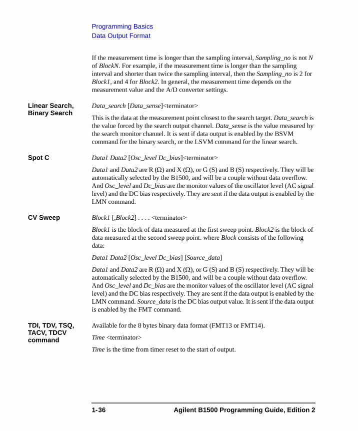
Programming BasicsData Output Format
If the measurement time is longer than the sampling interval, Sampling_no is not N of BlockN. For example, if the measurement time is longer than the sampling interval and shorter than twice the sampling interval, then the Sampling_no is 2 for Block1, and 4 for Block2. In general, the measurement time depends on the measurement value and the A/D converter settings.
Linear Search, Binary Search
Data_search [Data_sense]<terminator>
This is the data at the measurement point closest to the search target. Data_search is the value forced by the search output channel. Data_sense is the value measured by the search monitor channel. It is sent if data output is enabled by the BSVM command for the binary search, or the LSVM command for the linear search.
Spot C Data1 Data2 [Osc_level Dc_bias]<terminator>
Data1 and Data2 are R (Ω) and X (Ω), or G (S) and B (S) respectively. They will be automatically selected by the B1500, and will be a couple without data overflow. And Osc_level and Dc_bias are the monitor values of the oscillator level (AC signal level) and the DC bias respectively. They are sent if the data output is enabled by the LMN command.
CV Sweep Block1 [,Block2] . . . . <terminator>
Block1 is the block of data measured at the first sweep point. Block2 is the block of data measured at the second sweep point. where Block consists of the following data:
Data1 Data2 [Osc_level Dc_bias] [Source_data]
Data1 and Data2 are R (Ω) and X (Ω), or G (S) and B (S) respectively. They will be automatically selected by the B1500, and will be a couple without data overflow. And Osc_level and Dc_bias are the monitor values of the oscillator level (AC signal level) and the DC bias respectively. They are sent if the data output is enabled by the LMN command. Source_data is the DC bias output value. It is sent if the data output is enabled by the FMT command.
TDI, TDV, TSQ, TACV, TDCV command
Available for the 8 bytes binary data format (FMT13 or FMT14).
Time <terminator>
Time is the time from timer reset to the start of output.
1-36 Agilent B1500 Programming Guide, Edition 2
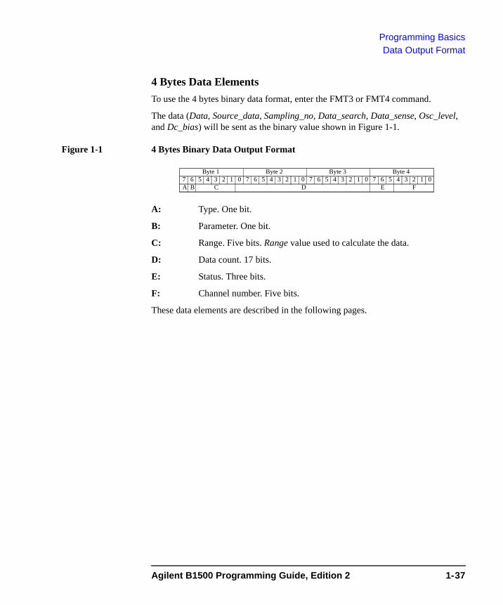
Programming BasicsData Output Format
4 Bytes Data ElementsTo use the 4 bytes binary data format, enter the FMT3 or FMT4 command.
The data (Data, Source_data, Sampling_no, Data_search, Data_sense, Osc_level, and Dc_bias) will be sent as the binary value shown in Figure 1-1.
Figure 1-1 4 Bytes Binary Data Output Format
A: Type. One bit.
B: Parameter. One bit.
C: Range. Five bits. Range value used to calculate the data.
D: Data count. 17 bits.
E: Status. Three bits.
F: Channel number. Five bits.
These data elements are described in the following pages.
6 5 4 3 2 1 07 6 5 4 3 2 1 07 6 5 4 3 2 1 07 6 5 4 3 2 1 07Byte 1 Byte 2 Byte 3 Byte 4
A B C D E F
Agilent B1500 Programming Guide, Edition 2 1-37
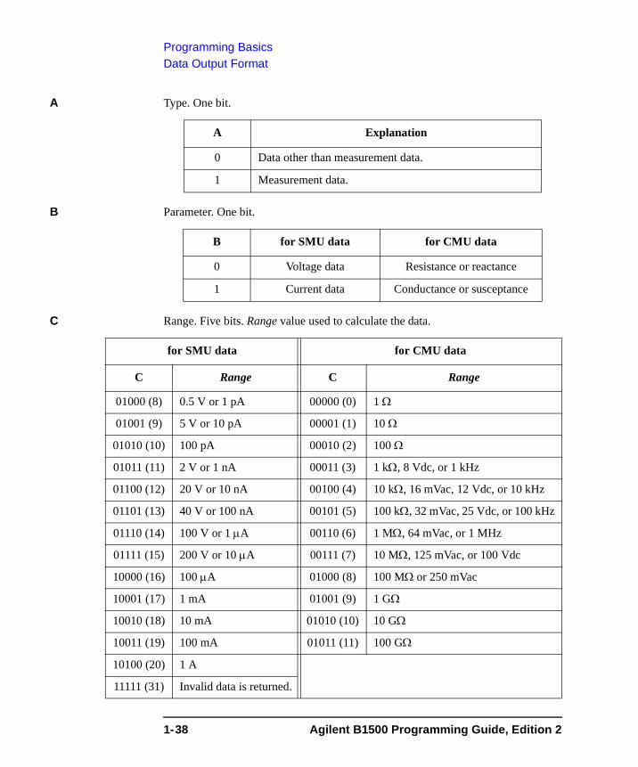
Programming BasicsData Output Format
A Type. One bit.
B Parameter. One bit.
C Range. Five bits. Range value used to calculate the data.
A Explanation
0 Data other than measurement data.
1 Measurement data.
B for SMU data for CMU data
0 Voltage data Resistance or reactance
1 Current data Conductance or susceptance
for SMU data for CMU data
C Range C Range
01000 (8) 0.5 V or 1 pA 00000 (0) 1 Ω
01001 (9) 5 V or 10 pA 00001 (1) 10 Ω
01010 (10) 100 pA 00010 (2) 100 Ω
01011 (11) 2 V or 1 nA 00011 (3) 1 kΩ, 8 Vdc, or 1 kHz
01100 (12) 20 V or 10 nA 00100 (4) 10 kΩ, 16 mVac, 12 Vdc, or 10 kHz
01101 (13) 40 V or 100 nA 00101 (5) 100 kΩ, 32 mVac, 25 Vdc, or 100 kHz
01110 (14) 100 V or 1 μA 00110 (6) 1 MΩ, 64 mVac, or 1 MHz
01111 (15) 200 V or 10 μA 00111 (7) 10 MΩ, 125 mVac, or 100 Vdc
10000 (16) 100 μA 01000 (8) 100 MΩ or 250 mVac
10001 (17) 1 mA 01001 (9) 1 GΩ
10010 (18) 10 mA 01010 (10) 10 GΩ
10011 (19) 100 mA 01011 (11) 100 GΩ
10100 (20) 1 A
11111 (31) Invalid data is returned.
1-38 Agilent B1500 Programming Guide, Edition 2
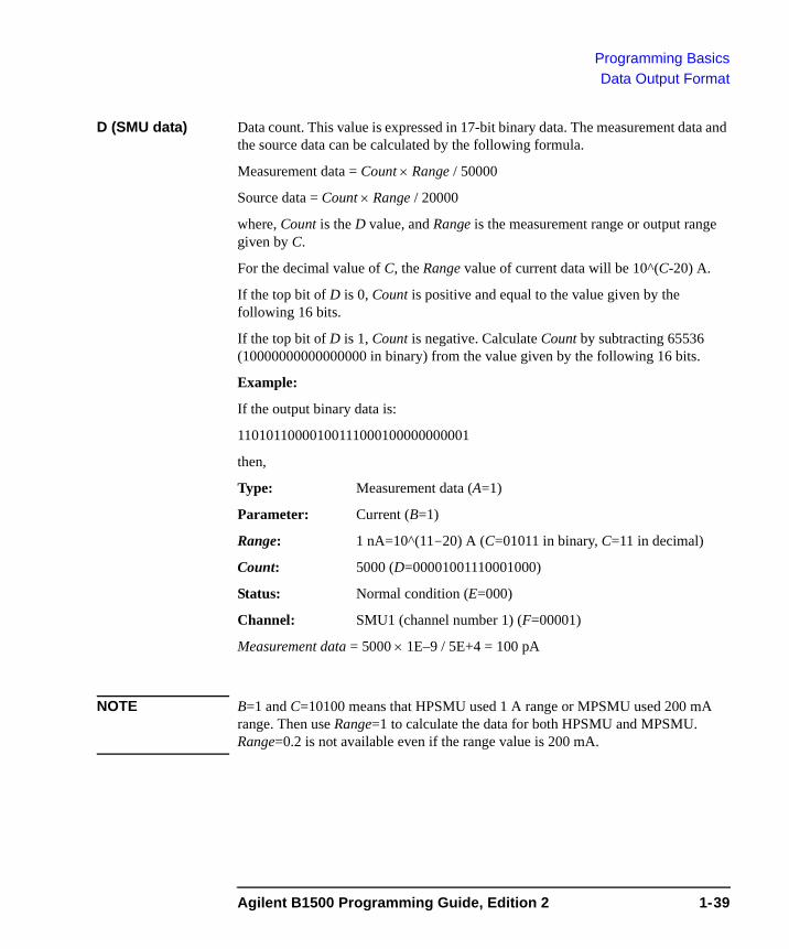
Programming BasicsData Output Format
D (SMU data) Data count. This value is expressed in 17-bit binary data. The measurement data and the source data can be calculated by the following formula.
Measurement data = Count × Range / 50000
Source data = Count × Range / 20000
where, Count is the D value, and Range is the measurement range or output range given by C.
For the decimal value of C, the Range value of current data will be 10^(C-20) A.
If the top bit of D is 0, Count is positive and equal to the value given by the following 16 bits.
If the top bit of D is 1, Count is negative. Calculate Count by subtracting 65536 (10000000000000000 in binary) from the value given by the following 16 bits.
Example:
If the output binary data is:
11010110000100111000100000000001
then,
Type: Measurement data (A=1)
Parameter: Current (B=1)
Range: 1 nA=10^(11-20) A (C=01011 in binary, C=11 in decimal)
Count: 5000 (D=00001001110001000)
Status: Normal condition (E=000)
Channel: SMU1 (channel number 1) (F=00001)
Measurement data = 5000 × 1E–9 / 5E+4 = 100 pA
NOTE B=1 and C=10100 means that HPSMU used 1 A range or MPSMU used 200 mA range. Then use Range=1 to calculate the data for both HPSMU and MPSMU. Range=0.2 is not available even if the range value is 200 mA.
Agilent B1500 Programming Guide, Edition 2 1-39
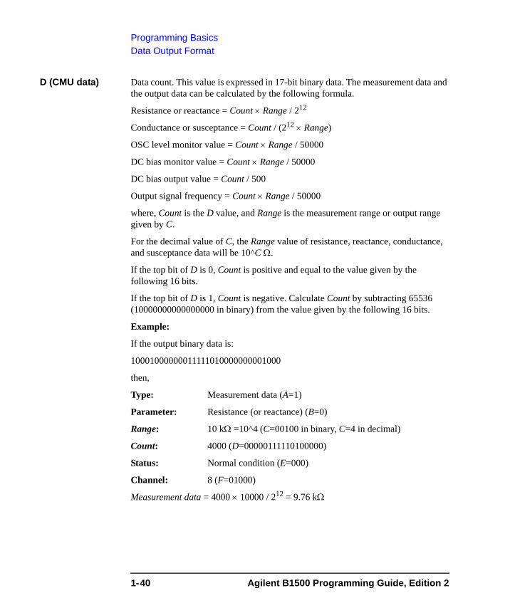
Programming BasicsData Output Format
D (CMU data) Data count. This value is expressed in 17-bit binary data. The measurement data and the output data can be calculated by the following formula.
Resistance or reactance = Count × Range / 212
Conductance or susceptance = Count / (212 × Range)
OSC level monitor value = Count × Range / 50000
DC bias monitor value = Count × Range / 50000
DC bias output value = Count / 500
Output signal frequency = Count × Range / 50000
where, Count is the D value, and Range is the measurement range or output range given by C.
For the decimal value of C, the Range value of resistance, reactance, conductance, and susceptance data will be 10^C Ω.
If the top bit of D is 0, Count is positive and equal to the value given by the following 16 bits.
If the top bit of D is 1, Count is negative. Calculate Count by subtracting 65536 (10000000000000000 in binary) from the value given by the following 16 bits.
Example:
If the output binary data is:
10001000000011111010000000001000
then,
Type: Measurement data (A=1)
Parameter: Resistance (or reactance) (B=0)
Range: 10 kΩ =10^4 (C=00100 in binary, C=4 in decimal)
Count: 4000 (D=00000111110100000)
Status: Normal condition (E=000)
Channel: 8 (F=01000)
Measurement data = 4000 × 10000 / 212 = 9.76 kΩ
1-40 Agilent B1500 Programming Guide, Edition 2
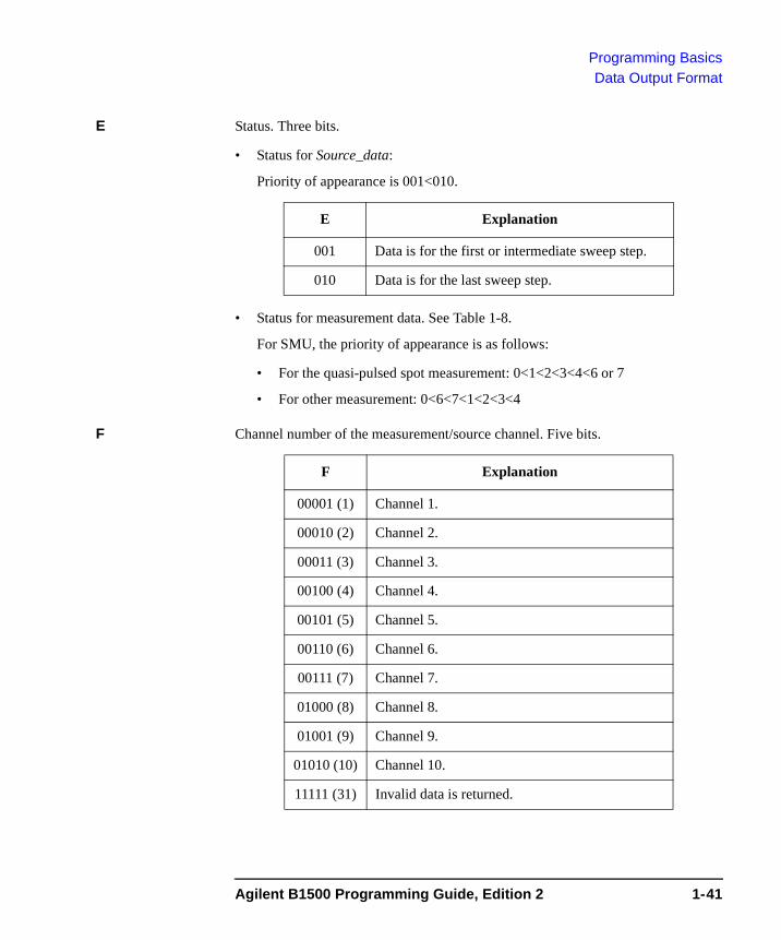
Programming BasicsData Output Format
E Status. Three bits.
• Status for Source_data:
Priority of appearance is 001<010.
• Status for measurement data. See Table 1-8.
For SMU, the priority of appearance is as follows:
• For the quasi-pulsed spot measurement: 0<1<2<3<4<6 or 7
• For other measurement: 0<6<7<1<2<3<4
F Channel number of the measurement/source channel. Five bits.
E Explanation
001 Data is for the first or intermediate sweep step.
010 Data is for the last sweep step.
F Explanation
00001 (1) Channel 1.
00010 (2) Channel 2.
00011 (3) Channel 3.
00100 (4) Channel 4.
00101 (5) Channel 5.
00110 (6) Channel 6.
00111 (7) Channel 7.
01000 (8) Channel 8.
01001 (9) Channel 9.
01010 (10) Channel 10.
11111 (31) Invalid data is returned.
Agilent B1500 Programming Guide, Edition 2 1-41
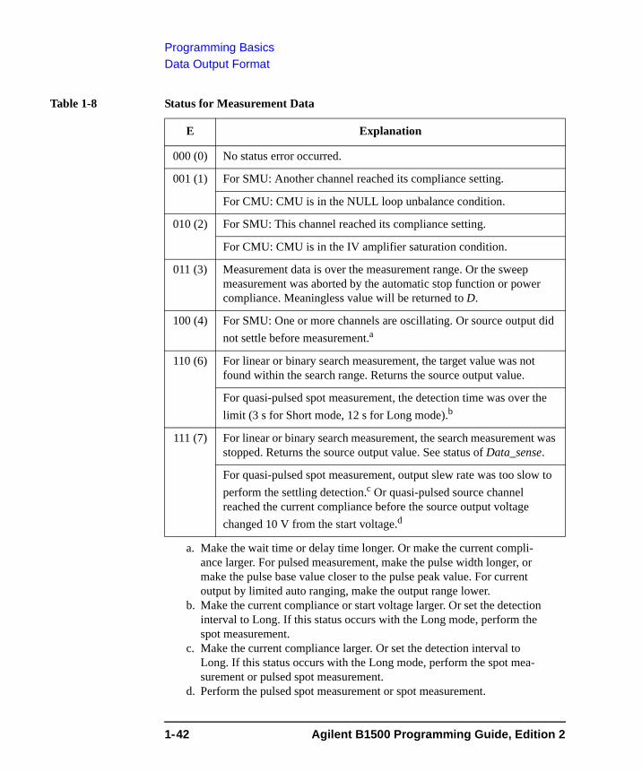
Programming BasicsData Output Format
Table 1-8 Status for Measurement Data
E Explanation
000 (0) No status error occurred.
001 (1) For SMU: Another channel reached its compliance setting.
For CMU: CMU is in the NULL loop unbalance condition.
010 (2) For SMU: This channel reached its compliance setting.
For CMU: CMU is in the IV amplifier saturation condition.
011 (3) Measurement data is over the measurement range. Or the sweep measurement was aborted by the automatic stop function or power compliance. Meaningless value will be returned to D.
100 (4) For SMU: One or more channels are oscillating. Or source output did not settle before measurement.a
a. Make the wait time or delay time longer. Or make the current compli-ance larger. For pulsed measurement, make the pulse width longer, or make the pulse base value closer to the pulse peak value. For current output by limited auto ranging, make the output range lower.
110 (6) For linear or binary search measurement, the target value was not found within the search range. Returns the source output value.
For quasi-pulsed spot measurement, the detection time was over the limit (3 s for Short mode, 12 s for Long mode).b
b. Make the current compliance or start voltage larger. Or set the detection interval to Long. If this status occurs with the Long mode, perform the spot measurement.
111 (7) For linear or binary search measurement, the search measurement was stopped. Returns the source output value. See status of Data_sense.
For quasi-pulsed spot measurement, output slew rate was too slow to perform the settling detection.c Or quasi-pulsed source channel reached the current compliance before the source output voltage changed 10 V from the start voltage.d
c. Make the current compliance larger. Or set the detection interval to Long. If this status occurs with the Long mode, perform the spot mea-surement or pulsed spot measurement.
d. Perform the pulsed spot measurement or spot measurement.
1-42 Agilent B1500 Programming Guide, Edition 2
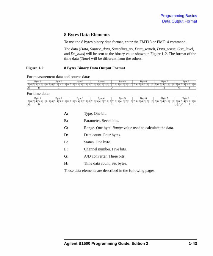
Programming BasicsData Output Format
8 Bytes Data ElementsTo use the 8 bytes binary data format, enter the FMT13 or FMT14 command.
The data (Data, Source_data, Sampling_no, Data_search, Data_sense, Osc_level, and Dc_bias) will be sent as the binary value shown in Figure 1-2. The format of the time data (Time) will be different from the others.
Figure 1-2 8 Bytes Binary Data Output Format
A: Type. One bit.
B: Parameter. Seven bits.
C: Range. One byte. Range value used to calculate the data.
D: Data count. Four bytes.
E: Status. One byte.
F: Channel number. Five bits.
G: A/D converter. Three bits.
H: Time data count. Six bytes.
These data elements are described in the following pages.
6 5 4 3 2 1 07 6 5 4 3 2 1 07 6 5 4 3 2 1 07 6 5 4 3 2 1 07Byte 5 Byte 6 Byte 7 Byte 8
6 5 4 3 2 1 07 6 5 4 3 2 1 07 6 5 4 3 2 1 07 6 5 4 3 2 1 07Byte 1 Byte 2 Byte 3 Byte 4
A B C D E G F
6 5 4 3 2 1 07 6 5 4 3 2 1 07 6 5 4 3 2 1 07 6 5 4 3 2 1 07Byte 5 Byte 6 Byte 7 Byte 8
6 5 4 3 2 1 07 6 5 4 3 2 1 07 6 5 4 3 2 1 07 6 5 4 3 2 1 07Byte 1 Byte 2 Byte 3 Byte 4
A B H F
For time data:
For measurement data and source data:
Agilent B1500 Programming Guide, Edition 2 1-43
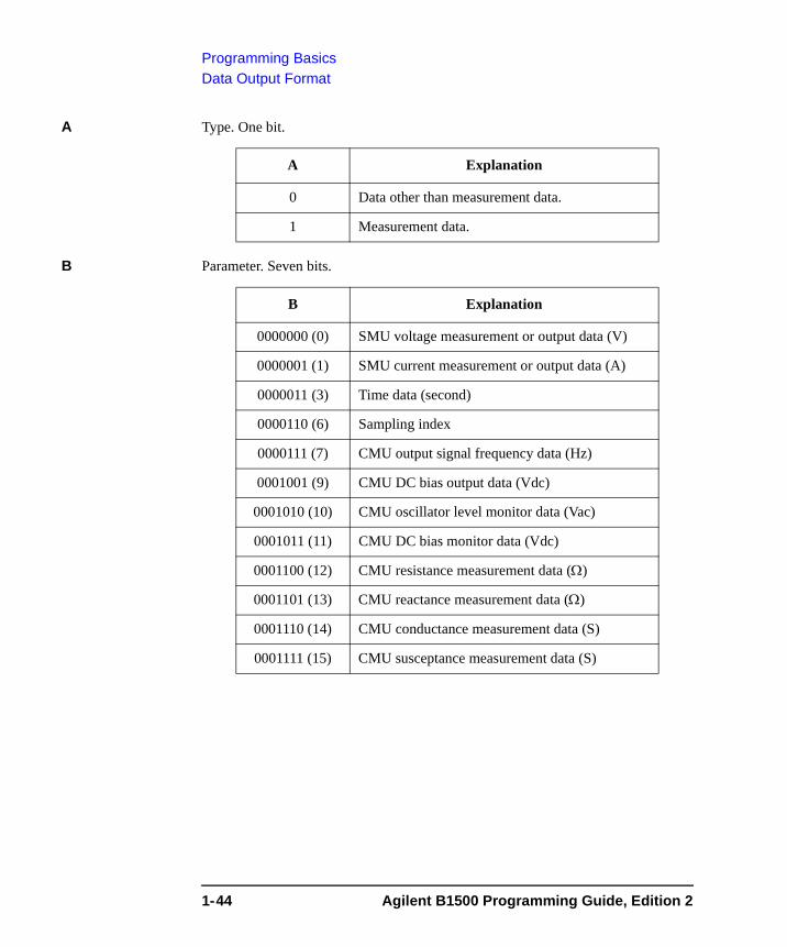
Programming BasicsData Output Format
A Type. One bit.
B Parameter. Seven bits.
A Explanation
0 Data other than measurement data.
1 Measurement data.
B Explanation
0000000 (0) SMU voltage measurement or output data (V)
0000001 (1) SMU current measurement or output data (A)
0000011 (3) Time data (second)
0000110 (6) Sampling index
0000111 (7) CMU output signal frequency data (Hz)
0001001 (9) CMU DC bias output data (Vdc)
0001010 (10) CMU oscillator level monitor data (Vac)
0001011 (11) CMU DC bias monitor data (Vdc)
0001100 (12) CMU resistance measurement data (Ω)
0001101 (13) CMU reactance measurement data (Ω)
0001110 (14) CMU conductance measurement data (S)
0001111 (15) CMU susceptance measurement data (S)
1-44 Agilent B1500 Programming Guide, Edition 2
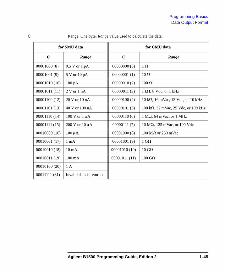
Programming BasicsData Output Format
C Range. One byte. Range value used to calculate the data.
for SMU data for CMU data
C Range C Range
00001000 (8) 0.5 V or 1 pA 00000000 (0) 1 Ω
00001001 (9) 5 V or 10 pA 00000001 (1) 10 Ω
00001010 (10) 100 pA 00000010 (2) 100 Ω
00001011 (11) 2 V or 1 nA 00000011 (3) 1 kΩ, 8 Vdc, or 1 kHz
00001100 (12) 20 V or 10 nA 00000100 (4) 10 kΩ, 16 mVac, 12 Vdc, or 10 kHz
00001101 (13) 40 V or 100 nA 00000101 (5) 100 kΩ, 32 mVac, 25 Vdc, or 100 kHz
00001110 (14) 100 V or 1 μA 00000110 (6) 1 MΩ, 64 mVac, or 1 MHz
00001111 (15) 200 V or 10 μA 00000111 (7) 10 MΩ, 125 mVac, or 100 Vdc
00010000 (16) 100 μA 00001000 (8) 100 MΩ or 250 mVac
00010001 (17) 1 mA 00001001 (9) 1 GΩ
00010010 (18) 10 mA 00001010 (10) 10 GΩ
00010011 (19) 100 mA 00001011 (11) 100 GΩ
00010100 (20) 1 A
00011111 (31) Invalid data is returned.
Agilent B1500 Programming Guide, Edition 2 1-45
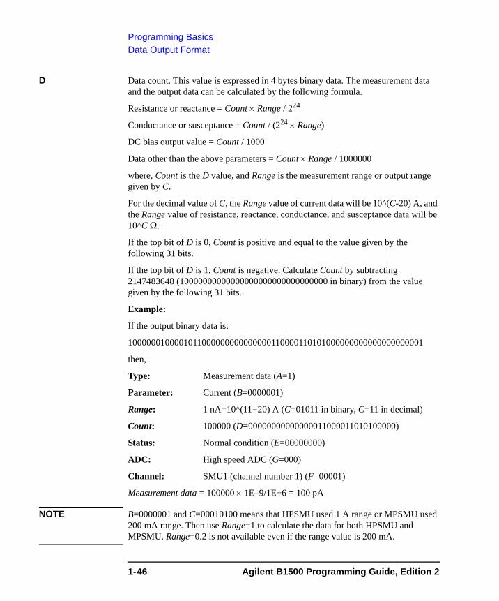
Programming BasicsData Output Format
D Data count. This value is expressed in 4 bytes binary data. The measurement data and the output data can be calculated by the following formula.
Resistance or reactance = Count × Range / 224
Conductance or susceptance = Count / (224 × Range)
DC bias output value = Count / 1000
Data other than the above parameters = Count × Range / 1000000
where, Count is the D value, and Range is the measurement range or output range given by C.
For the decimal value of C, the Range value of current data will be 10^(C-20) A, and the Range value of resistance, reactance, conductance, and susceptance data will be 10^C Ω.
If the top bit of D is 0, Count is positive and equal to the value given by the following 31 bits.
If the top bit of D is 1, Count is negative. Calculate Count by subtracting 2147483648 (10000000000000000000000000000000 in binary) from the value given by the following 31 bits.
Example:
If the output binary data is:
1000000100001011000000000000000110000110101000000000000000000001
then,
Type: Measurement data (A=1)
Parameter: Current (B=0000001)
Range: 1 nA=10^(11-20) A (C=01011 in binary, C=11 in decimal)
Count: 100000 (D=00000000000000011000011010100000)
Status: Normal condition (E=00000000)
ADC: High speed ADC (G=000)
Channel: SMU1 (channel number 1) (F=00001)
Measurement data = 100000 × 1E–9/1E+6 = 100 pA
NOTE B=0000001 and C=00010100 means that HPSMU used 1 A range or MPSMU used 200 mA range. Then use Range=1 to calculate the data for both HPSMU and MPSMU. Range=0.2 is not available even if the range value is 200 mA.
1-46 Agilent B1500 Programming Guide, Edition 2

Programming BasicsData Output Format
E Status. One byte. Meaningless for the Time data.
• Status for Source_data:
Priority of appearance is 001<010.
• Status for measurement data. See Table 1-9.
For SMU, the priority of appearance is as follows:
• For the quasi-pulsed spot measurement: 0<1<2<4<8<16 or 32
• For other measurement: 0<16<32<1<2<4<8
F Channel number of the measurement/source channel. Five bits.
E Explanation
00000001 Data is for the first or intermediate sweep step.
00000010 Data is for the last sweep step.
F Explanation
00001 (1) Channel 1.
00010 (2) Channel 2.
00011 (3) Channel 3.
00100 (4) Channel 4.
00101 (5) Channel 5.
00110 (6) Channel 6.
00111 (7) Channel 7.
01000 (8) Channel 8.
01001 (9) Channel 9.
01010 (10) Channel 10.
11010 (26) Status code for extraneous data in the channel. TSQ command response or invalid data is returned.
11111 (31) Invalid data is returned.
Agilent B1500 Programming Guide, Edition 2 1-47
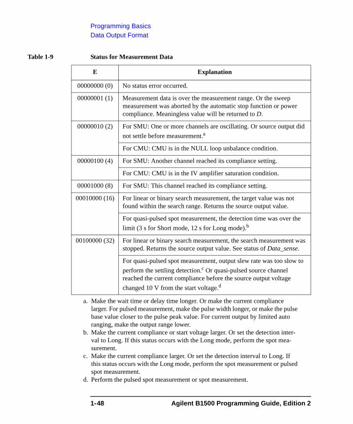
Programming BasicsData Output Format
Table 1-9 Status for Measurement Data
E Explanation
00000000 (0) No status error occurred.
00000001 (1) Measurement data is over the measurement range. Or the sweep measurement was aborted by the automatic stop function or power compliance. Meaningless value will be returned to D.
00000010 (2) For SMU: One or more channels are oscillating. Or source output did not settle before measurement.a
a. Make the wait time or delay time longer. Or make the current compliance larger. For pulsed measurement, make the pulse width longer, or make the pulse base value closer to the pulse peak value. For current output by limited auto ranging, make the output range lower.
For CMU: CMU is in the NULL loop unbalance condition.
00000100 (4) For SMU: Another channel reached its compliance setting.
For CMU: CMU is in the IV amplifier saturation condition.
00001000 (8) For SMU: This channel reached its compliance setting.
00010000 (16) For linear or binary search measurement, the target value was not found within the search range. Returns the source output value.
For quasi-pulsed spot measurement, the detection time was over the limit (3 s for Short mode, 12 s for Long mode).b
b. Make the current compliance or start voltage larger. Or set the detection inter-val to Long. If this status occurs with the Long mode, perform the spot mea-surement.
00100000 (32) For linear or binary search measurement, the search measurement was stopped. Returns the source output value. See status of Data_sense.
For quasi-pulsed spot measurement, output slew rate was too slow to perform the settling detection.c Or quasi-pulsed source channel reached the current compliance before the source output voltage changed 10 V from the start voltage.d
c. Make the current compliance larger. Or set the detection interval to Long. If this status occurs with the Long mode, perform the spot measurement or pulsed spot measurement.
d. Perform the pulsed spot measurement or spot measurement.
1-48 Agilent B1500 Programming Guide, Edition 2
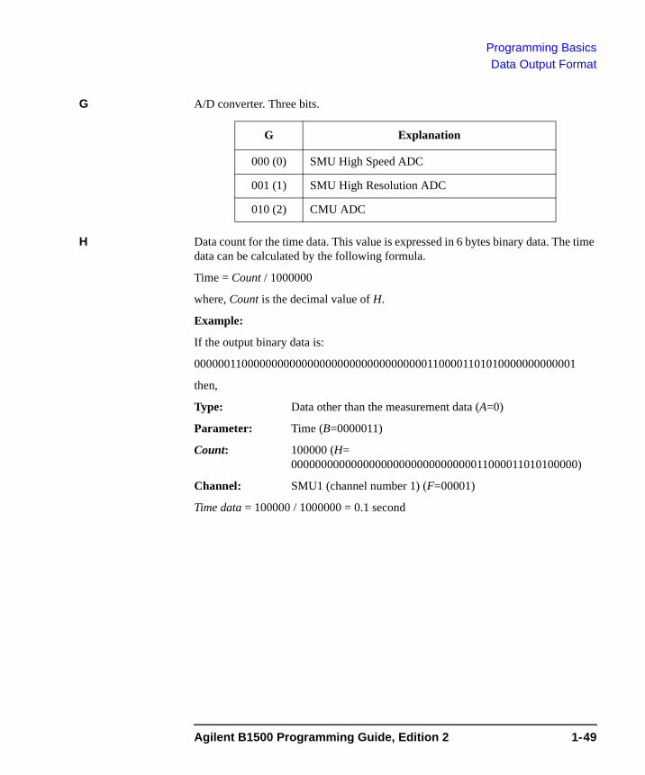
Programming BasicsData Output Format
G A/D converter. Three bits.
H Data count for the time data. This value is expressed in 6 bytes binary data. The time data can be calculated by the following formula.
Time = Count / 1000000
where, Count is the decimal value of H.
Example:
If the output binary data is:
0000001100000000000000000000000000000001100001101010000000000001
then,
Type: Data other than the measurement data (A=0)
Parameter: Time (B=0000011)
Count: 100000 (H= 000000000000000000000000000000011000011010100000)
Channel: SMU1 (channel number 1) (F=00001)
Time data = 100000 / 1000000 = 0.1 second
G Explanation
000 (0) SMU High Speed ADC
001 (1) SMU High Resolution ADC
010 (2) CMU ADC
Agilent B1500 Programming Guide, Edition 2 1-49
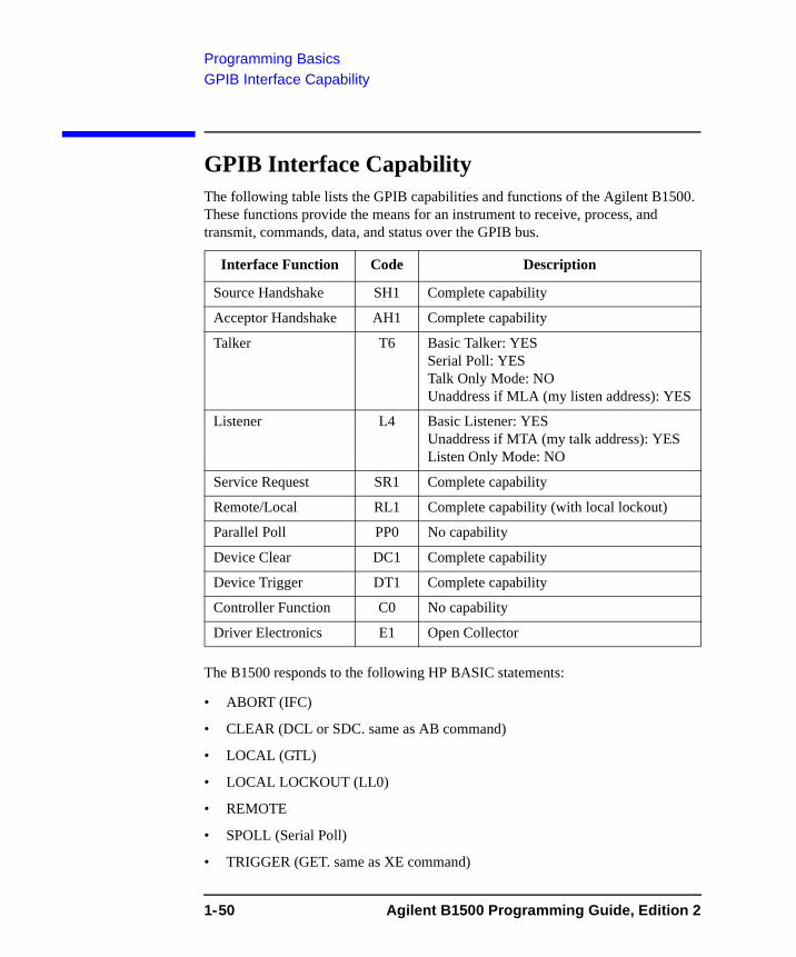
Programming BasicsGPIB Interface Capability
GPIB Interface CapabilityThe following table lists the GPIB capabilities and functions of the Agilent B1500. These functions provide the means for an instrument to receive, process, and transmit, commands, data, and status over the GPIB bus.
The B1500 responds to the following HP BASIC statements:
• ABORT (IFC)
• CLEAR (DCL or SDC. same as AB command)
• LOCAL (GTL)
• LOCAL LOCKOUT (LL0)
• REMOTE
• SPOLL (Serial Poll)
• TRIGGER (GET. same as XE command)
Interface Function Code Description
Source Handshake SH1 Complete capability
Acceptor Handshake AH1 Complete capability
Talker T6 Basic Talker: YESSerial Poll: YESTalk Only Mode: NOUnaddress if MLA (my listen address): YES
Listener L4 Basic Listener: YESUnaddress if MTA (my talk address): YESListen Only Mode: NO
Service Request SR1 Complete capability
Remote/Local RL1 Complete capability (with local lockout)
Parallel Poll PP0 No capability
Device Clear DC1 Complete capability
Device Trigger DT1 Complete capability
Controller Function C0 No capability
Driver Electronics E1 Open Collector
1-50 Agilent B1500 Programming Guide, Edition 2
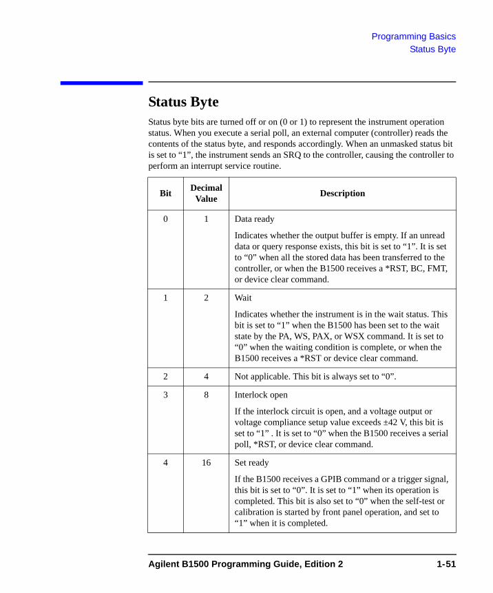
Programming BasicsStatus Byte
Status Byte Status byte bits are turned off or on (0 or 1) to represent the instrument operation status. When you execute a serial poll, an external computer (controller) reads the contents of the status byte, and responds accordingly. When an unmasked status bit is set to “1”, the instrument sends an SRQ to the controller, causing the controller to perform an interrupt service routine.
Bit Decimal Value Description
0 1 Data ready
Indicates whether the output buffer is empty. If an unread data or query response exists, this bit is set to “1”. It is set to “0” when all the stored data has been transferred to the controller, or when the B1500 receives a *RST, BC, FMT, or device clear command.
1 2 Wait
Indicates whether the instrument is in the wait status. This bit is set to “1” when the B1500 has been set to the wait state by the PA, WS, PAX, or WSX command. It is set to “0” when the waiting condition is complete, or when the B1500 receives a *RST or device clear command.
2 4 Not applicable. This bit is always set to “0”.
3 8 Interlock open
If the interlock circuit is open, and a voltage output or voltage compliance setup value exceeds ±42 V, this bit is set to “1” . It is set to “0” when the B1500 receives a serial poll, *RST, or device clear command.
4 16 Set ready
If the B1500 receives a GPIB command or a trigger signal, this bit is set to “0”. It is set to “1” when its operation is completed. This bit is also set to “0” when the self-test or calibration is started by front panel operation, and set to “1” when it is completed.
Agilent B1500 Programming Guide, Edition 2 1-51
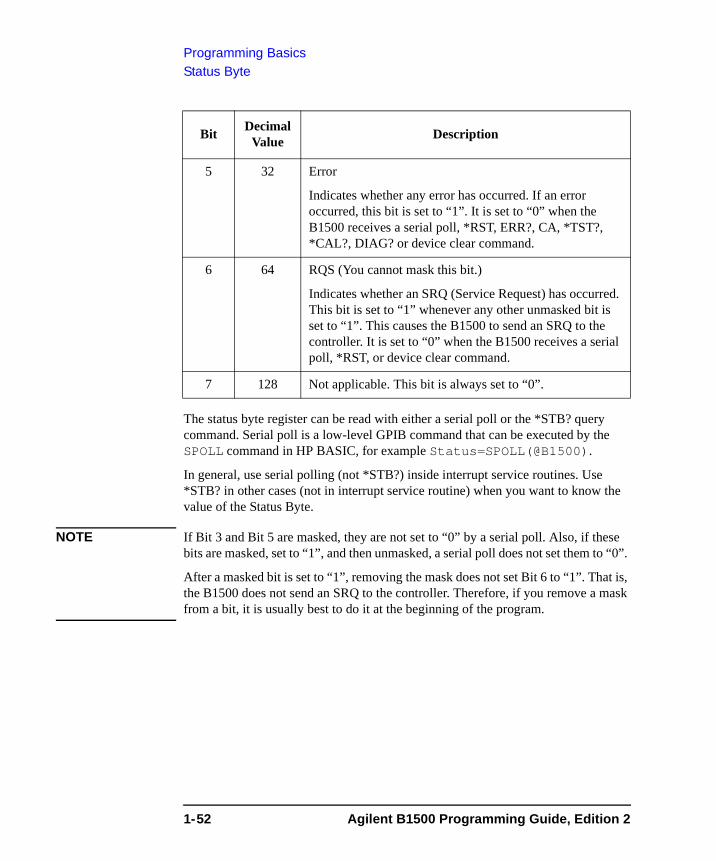
Programming BasicsStatus Byte
The status byte register can be read with either a serial poll or the *STB? query command. Serial poll is a low-level GPIB command that can be executed by the SPOLL command in HP BASIC, for example Status=SPOLL(@B1500).
In general, use serial polling (not *STB?) inside interrupt service routines. Use *STB? in other cases (not in interrupt service routine) when you want to know the value of the Status Byte.
NOTE If Bit 3 and Bit 5 are masked, they are not set to “0” by a serial poll. Also, if these bits are masked, set to “1”, and then unmasked, a serial poll does not set them to “0”.
After a masked bit is set to “1”, removing the mask does not set Bit 6 to “1”. That is, the B1500 does not send an SRQ to the controller. Therefore, if you remove a mask from a bit, it is usually best to do it at the beginning of the program.
5 32 Error
Indicates whether any error has occurred. If an error occurred, this bit is set to “1”. It is set to “0” when the B1500 receives a serial poll, *RST, ERR?, CA, *TST?, *CAL?, DIAG? or device clear command.
6 64 RQS (You cannot mask this bit.)
Indicates whether an SRQ (Service Request) has occurred. This bit is set to “1” whenever any other unmasked bit is set to “1”. This causes the B1500 to send an SRQ to the controller. It is set to “0” when the B1500 receives a serial poll, *RST, or device clear command.
7 128 Not applicable. This bit is always set to “0”.
Bit Decimal Value Description
1-52 Agilent B1500 Programming Guide, Edition 2
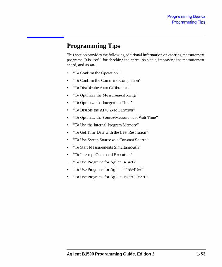
Programming BasicsProgramming Tips
Programming Tips This section provides the following additional information on creating measurement programs. It is useful for checking the operation status, improving the measurement speed, and so on.
• “To Confirm the Operation”
• “To Confirm the Command Completion”
• “To Disable the Auto Calibration”
• “To Optimize the Measurement Range”
• “To Optimize the Integration Time”
• “To Disable the ADC Zero Function”
• “To Optimize the Source/Measurement Wait Time”
• “To Use the Internal Program Memory”
• “To Get Time Data with the Best Resolution”
• “To Use Sweep Source as a Constant Source”
• “To Start Measurements Simultaneously”
• “To Interrupt Command Execution”
• “To Use Programs for Agilent 4142B”
• “To Use Programs for Agilent 4155/4156”
• “To Use Programs for Agilent E5260/E5270”
Agilent B1500 Programming Guide, Edition 2 1-53
Programming BasicsProgramming Tips
To Confirm the OperationTo complete the measurement program, you can insert statements to check the B1500 operation status as shown below. This example starts the measurement, checks the status caused by the statements before the ERR? command, reads and displays the measurement data without errors, or displays an error message when an error occurs.
OUTPUT @B1500;"XE"OUTPUT @B1500;"ERR? 1"ENTER @B1500;CodeIF Code=0 THEN
ENTER @B1500 USING "#,3X,12D,X";Mdata PRINT "I(A)=";MdataELSE OUTPUT @B1500;"EMG? ";Code
ENTER @B1500;Msg$ PRINT "ERROR: ";Msg$END IF
To Confirm the Command CompletionTo check the completion of the previous command execution, use the *OPC? query command. Entering the *OPC command before sending a command to other equipment serves to delay its operation until the B1500 has completed its operation. The *OPC? command is useful to control equipments sequentially.
For example, the following program segment waits until the B1500 completes the DI command execution, and sends the XYZ command to equipment identified by @Address.
OUTPUT @B1500;"DI";1,0,1.0E-10,1OUTPUT @B1500;"*OPC?"ENTER @B1500; A$OUTPUT @Address;"XYZ"
To Disable the Auto CalibrationThe auto calibration function triggers self-calibration automatically every 30 minutes after measurement. When the function is enabled, open the measurement terminals frequently because calibration requires open terminals.
If you execute automatic measurements as a batch job that might leave the device connected for over 30 minutes after the measurements, disable auto calibration. Otherwise, the calibration might not be performed properly, or unexpected output might appear at the measurement terminals, and it could even damage the device. To disable auto calibration, send the CM 0 command.
1-54 Agilent B1500 Programming Guide, Edition 2
Programming BasicsProgramming Tips
To Optimize the Measurement RangeThe most effective way to improve measurement speed is to reduce the number of range changes. The limited auto ranging mode is more effective than the auto ranging mode. The fixed range mode is the most effective.
Check the typical value of the measurement data, select the optimum range, and perform measurement using the fixed range mode.
To Optimize the Integration TimeFor best reliability and repeatability of the measurement data, the integration time or the number of averaging samples of the A/D converter must be increased. This increases the measurement time.
A long integration time and numerous samples are required for low current/ voltage measurements. However, the values can be decreased for medium or high current/voltage measurements. Enter the following commands:
AV Sets the number of averaging samples of the A/D converter. This command is compatible with the AV command of the Agilent 4142B.
AAD Selects the type of the A/D converter (high-speed ADC or high-resolution ADC).
AIT Sets the integration time of the high-resolution ADC or the number of averaging samples of the high-speed ADC. The AIT command covers the function of the AV command. The last command setting is available for the measurement.
For more information regarding these commands, see Chapter 4, “Command Reference.”
To Disable the ADC Zero FunctionThis information is effective only when the high resolution A/D converter is used for the measurement. If measurement speed is given top priority or is more important than reliability, disable the ADC zero function by sending the AZ 0 command. This roughly halves integration time.
NOTE The ADC zero function is the function to cancel offset of the high resolution ADC. This function is especially effective for low voltage measurements.
Agilent B1500 Programming Guide, Edition 2 1-55
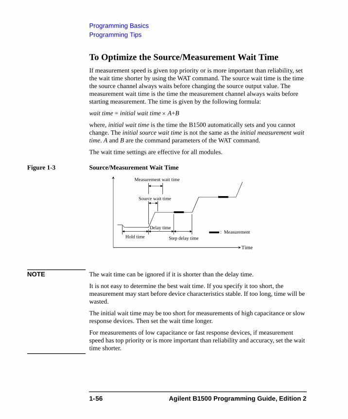
Programming BasicsProgramming Tips
To Optimize the Source/Measurement Wait TimeIf measurement speed is given top priority or is more important than reliability, set the wait time shorter by using the WAT command. The source wait time is the time the source channel always waits before changing the source output value. The measurement wait time is the time the measurement channel always waits before starting measurement. The time is given by the following formula:
wait time = initial wait time × A+B
where, initial wait time is the time the B1500 automatically sets and you cannot change. The initial source wait time is not the same as the initial measurement wait time. A and B are the command parameters of the WAT command.
The wait time settings are effective for all modules.
Figure 1-3 Source/Measurement Wait Time
NOTE The wait time can be ignored if it is shorter than the delay time.
It is not easy to determine the best wait time. If you specify it too short, the measurement may start before device characteristics stable. If too long, time will be wasted.
The initial wait time may be too short for measurements of high capacitance or slow response devices. Then set the wait time longer.
For measurements of low capacitance or fast response devices, if measurement speed has top priority or is more important than reliability and accuracy, set the wait time shorter.
Measurement wait time
Time
: MeasurementHold time
Delay time
Source wait time
Step delay time
1-56 Agilent B1500 Programming Guide, Edition 2
Programming BasicsProgramming Tips
To Use the Internal Program MemoryIf your program repeats the setup and measurement for a number of devices, use the internal program memory. For these measurements, using the internal program memory reduces the command transfer time, and improves the program execution speed.
You can enter a maximum of 2,000 programs (total 40,000 commands) into the internal program memory. See Chapter 2, “Remote Mode Functions.”
To Get Time Data with the Best ResolutionTo read the time data with the best resolution (100 μs), the timer must be cleared within the following interval:
• 100 sec or less (for FMT1, 2, or 5 data output format)
• 1000 sec or less (for FMT 11, 12, 15, 21, 22, or 25 data output format)
Send the TSR command to clear the timer.
To Use Sweep Source as a Constant SourceThe following setup enables sweep source to force a constant current or voltage.
• Sweep start value = Sweep stop value (for WI, WV, or WNX).
Also, setting number of sweep steps to 1 enables to perform a spot measurement.
To Start Measurements SimultaneouslySpot measurement, staircase sweep measurement, and multi channel sweep measurement enable to use multiple measurement channels. Then the measurement channels perform measurement in the order defined in the MM command. However, the measurement channels with the following setup start measurements simultaneously.
• To set the multi channel sweep measurement mode (MM 16).
• To set the measurement ranging mode to fixed (for RI or RV).
• To use the high-speed ADC (use AV).
NOTE Measurement setup is independent from source output setup. So, this simultaneous measurement cannot be broken by the source output setup. Any setting of the output ranging mode is effective for the simultaneous measurement.
Agilent B1500 Programming Guide, Edition 2 1-57
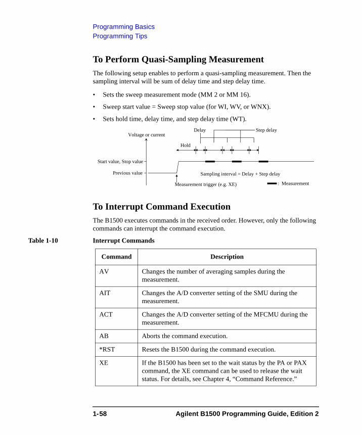
Programming BasicsProgramming Tips
To Perform Quasi-Sampling MeasurementThe following setup enables to perform a quasi-sampling measurement. Then the sampling interval will be sum of delay time and step delay time.
• Sets the sweep measurement mode (MM 2 or MM 16).
• Sweep start value = Sweep stop value (for WI, WV, or WNX).
• Sets hold time, delay time, and step delay time (WT).
To Interrupt Command ExecutionThe B1500 executes commands in the received order. However, only the following commands can interrupt the command execution.
Table 1-10 Interrupt Commands
Voltage or current
Measurement trigger (e.g. XE)
Hold
Start value, Stop value
Previous value
: Measurement
Delay Step delay
Sampling interval = Delay + Step delay
Command Description
AV Changes the number of averaging samples during the measurement.
AIT Changes the A/D converter setting of the SMU during the measurement.
ACT Changes the A/D converter setting of the MFCMU during the measurement.
AB Aborts the command execution.
*RST Resets the B1500 during the command execution.
XE If the B1500 has been set to the wait status by the PA or PAX command, the XE command can be used to release the wait status. For details, see Chapter 4, “Command Reference.”
1-58 Agilent B1500 Programming Guide, Edition 2
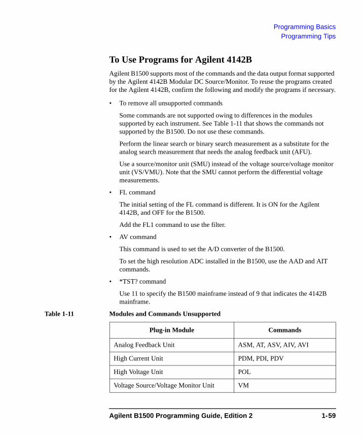
Programming BasicsProgramming Tips
To Use Programs for Agilent 4142BAgilent B1500 supports most of the commands and the data output format supported by the Agilent 4142B Modular DC Source/Monitor. To reuse the programs created for the Agilent 4142B, confirm the following and modify the programs if necessary.
• To remove all unsupported commands
Some commands are not supported owing to differences in the modules supported by each instrument. See Table 1-11 that shows the commands not supported by the B1500. Do not use these commands.
Perform the linear search or binary search measurement as a substitute for the analog search measurement that needs the analog feedback unit (AFU).
Use a source/monitor unit (SMU) instead of the voltage source/voltage monitor unit (VS/VMU). Note that the SMU cannot perform the differential voltage measurements.
• FL command
The initial setting of the FL command is different. It is ON for the Agilent 4142B, and OFF for the B1500.
Add the FL1 command to use the filter.
• AV command
This command is used to set the A/D converter of the B1500.
To set the high resolution ADC installed in the B1500, use the AAD and AIT commands.
• *TST? command
Use 11 to specify the B1500 mainframe instead of 9 that indicates the 4142B mainframe.
Table 1-11 Modules and Commands Unsupported
Plug-in Module Commands
Analog Feedback Unit ASM, AT, ASV, AIV, AVI
High Current Unit PDM, PDI, PDV
High Voltage Unit POL
Voltage Source/Voltage Monitor Unit VM
Agilent B1500 Programming Guide, Edition 2 1-59
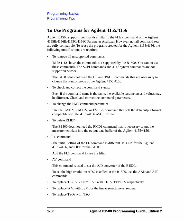
Programming BasicsProgramming Tips
To Use Programs for Agilent 4155/4156Agilent B1500 supports commands similar to the FLEX command of the Agilent 4155B/4156B/4155C/4156C Parameter Analyzer. However, not all command sets are fully compatible. To reuse the programs created for the Agilent 4155/4156, the following modifications are required.
• To remove all unsupported commands
Table 1-12 shows the commands not supported by the B1500. You cannot use these commands. The SCPI commands and 4145 syntax commands are not supported neither.
The B1500 does not need the US and :PAGE commands that are necessary to change the control mode of the Agilent 4155/4156.
• To check and correct the command syntax
Even if the command name is the same, the available parameters and values may be different. Check and correct the command parameters.
• To change the FMT command parameter
Use the FMT 21, FMT 22, or FMT 25 command that sets the data output format compatible with the 4155/4156 ASCII format.
• To delete RMD?
The B1500 does not need the RMD? command that is necessary to put the measurement data into the output data buffer of the Agilent 4155/4156.
• FL command
The initial setting of the FL command is different. It is ON for the Agilent 4155/4156, and OFF for the B1500.
Add the FL1 command to use the filter.
• AV command
This command is used to set the A/D converter of the B1500.
To set the high resolution ADC installed in the B1500, use the AAD and AIT commands.
• To replace TI?/TV?/TTI?/TTV? with TI/TV/TTI/TTV respectively
• To replace WM with LSM for the linear search measurement
• To replace TSQ? with TSQ
1-60 Agilent B1500 Programming Guide, Edition 2
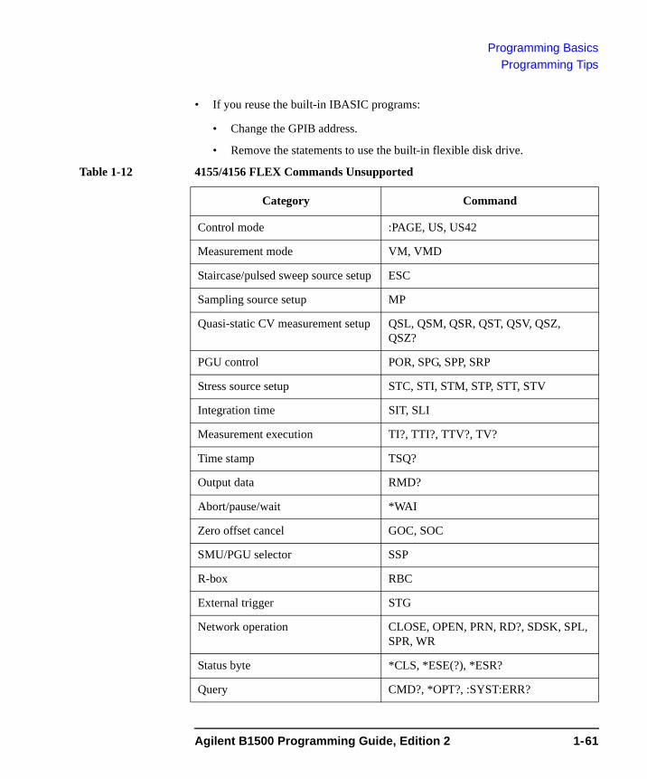
Programming BasicsProgramming Tips
• If you reuse the built-in IBASIC programs:
• Change the GPIB address.
• Remove the statements to use the built-in flexible disk drive.
Table 1-12 4155/4156 FLEX Commands Unsupported
Category Command
Control mode :PAGE, US, US42
Measurement mode VM, VMD
Staircase/pulsed sweep source setup ESC
Sampling source setup MP
Quasi-static CV measurement setup QSL, QSM, QSR, QST, QSV, QSZ, QSZ?
PGU control POR, SPG, SPP, SRP
Stress source setup STC, STI, STM, STP, STT, STV
Integration time SIT, SLI
Measurement execution TI?, TTI?, TTV?, TV?
Time stamp TSQ?
Output data RMD?
Abort/pause/wait *WAI
Zero offset cancel GOC, SOC
SMU/PGU selector SSP
R-box RBC
External trigger STG
Network operation CLOSE, OPEN, PRN, RD?, SDSK, SPL, SPR, WR
Status byte *CLS, *ESE(?), *ESR?
Query CMD?, *OPT?, :SYST:ERR?
Agilent B1500 Programming Guide, Edition 2 1-61
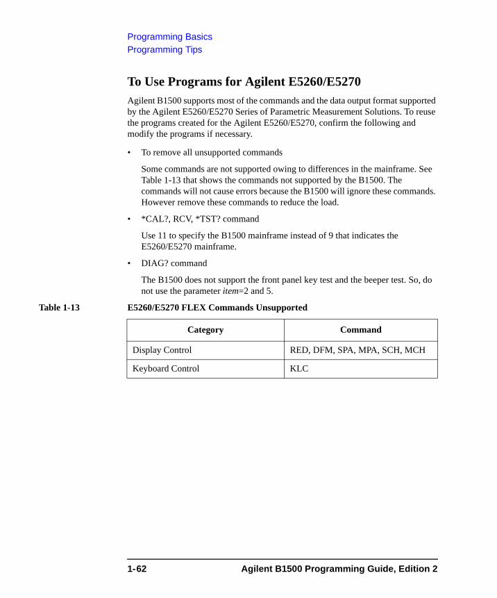
Programming BasicsProgramming Tips
To Use Programs for Agilent E5260/E5270Agilent B1500 supports most of the commands and the data output format supported by the Agilent E5260/E5270 Series of Parametric Measurement Solutions. To reuse the programs created for the Agilent E5260/E5270, confirm the following and modify the programs if necessary.
• To remove all unsupported commands
Some commands are not supported owing to differences in the mainframe. See Table 1-13 that shows the commands not supported by the B1500. The commands will not cause errors because the B1500 will ignore these commands. However remove these commands to reduce the load.
• *CAL?, RCV, *TST? command
Use 11 to specify the B1500 mainframe instead of 9 that indicates the E5260/E5270 mainframe.
• DIAG? command
The B1500 does not support the front panel key test and the beeper test. So, do not use the parameter item=2 and 5.
Table 1-13 E5260/E5270 FLEX Commands Unsupported
Category Command
Display Control RED, DFM, SPA, MPA, SCH, MCH
Keyboard Control KLC
1-62 Agilent B1500 Programming Guide, Edition 2
2 Remote Mode Functions
Remote Mode Functions
This chapter describes the functions of the Agilent B1500 in the remote mode, and the initial settings.
• “Measurement Modes”
• “Synchronous Output”
• “Automatic Abort Function”
• “Parallel Measurement Function”
• “Program Memory”
• “Digital I/O Port”
• “Trigger Function”
• “Initial Settings”
NOTE Synchronous Output
You can use synchronous output that will be synchronized to the output of the primary sweep or search source. The output is available for the following measurement modes:
• “Staircase Sweep Measurements”
• “Pulsed Sweep Measurements”
• “Staircase Sweep with Pulsed Bias Measurements”
• “Binary Search Measurements”
• “Linear Search Measurements”
The synchronous source supports the output mode (voltage or current) same as the primary source, and does not support the pulsed output.
2-2 Agilent B1500 Programming Guide, Edition 2
Remote Mode FunctionsMeasurement Modes
Measurement ModesThe Agilent B1500 provides the following measurement modes.
• “Spot Measurements”
• “Pulsed Spot Measurements”
• “Staircase Sweep Measurements”
• “Multi Channel Sweep Measurements”
• “Pulsed Sweep Measurements”
• “Staircase Sweep with Pulsed Bias Measurements”
• “Quasi-Pulsed Spot Measurements”
• “Binary Search Measurements”
• “Linear Search Measurements”
• “Sampling Measurement”
• “Spot C Measurement”
• “CV Sweep Measurement”
NOTE About Search Measurements
The B1500 supports search measurement to find a point on an I-V curve where a specified condition is satisfied. For example, it searches for a breakdown voltage or threshold voltage at a specified current.
Search measurements are performed by one or two SMUs. For two SMUs, one is the search channel, and the other is a sense channel. When one SMU is used, it serves as both search and sense channel.
Basically, the search channel forces voltage or current until the search stop condition is satisfied.
Agilent B1500 Programming Guide, Edition 2 2-3
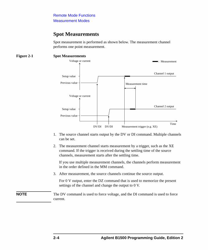
Remote Mode FunctionsMeasurement Modes
Spot MeasurementsSpot measurement is performed as shown below. The measurement channel performs one point measurement.
Figure 2-1 Spot Measurements
1. The source channel starts output by the DV or DI command. Multiple channels can be set.
2. The measurement channel starts measurement by a trigger, such as the XE command. If the trigger is received during the settling time of the source channels, measurement starts after the settling time.
If you use multiple measurement channels, the channels perform measurement in the order defined in the MM command.
3. After measurement, the source channels continue the source output.
For 0 V output, enter the DZ command that is used to memorize the present settings of the channel and change the output to 0 V.
NOTE The DV command is used to force voltage, and the DI command is used to force current.
Voltage or current
DV/DI DV/DI Measurement trigger (e.g. XE)
Measurement time
Channel 1 output
Channel 2 output
Setup value
Previous value
Setup value
Previous value
Voltage or current
Time
: Measurement
2-4 Agilent B1500 Programming Guide, Edition 2
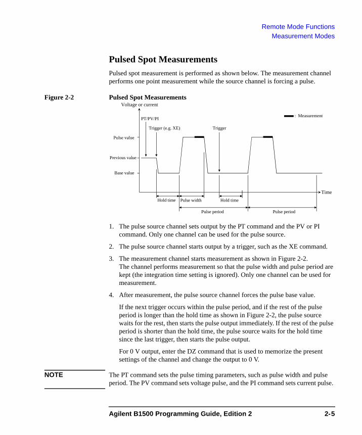
Remote Mode FunctionsMeasurement Modes
Pulsed Spot MeasurementsPulsed spot measurement is performed as shown below. The measurement channel performs one point measurement while the source channel is forcing a pulse.
Figure 2-2 Pulsed Spot Measurements
1. The pulse source channel sets output by the PT command and the PV or PI command. Only one channel can be used for the pulse source.
2. The pulse source channel starts output by a trigger, such as the XE command.
3. The measurement channel starts measurement as shown in Figure 2-2. The channel performs measurement so that the pulse width and pulse period are kept (the integration time setting is ignored). Only one channel can be used for measurement.
4. After measurement, the pulse source channel forces the pulse base value.
If the next trigger occurs within the pulse period, and if the rest of the pulse period is longer than the hold time as shown in Figure 2-2, the pulse source waits for the rest, then starts the pulse output immediately. If the rest of the pulse period is shorter than the hold time, the pulse source waits for the hold time since the last trigger, then starts the pulse output.
For 0 V output, enter the DZ command that is used to memorize the present settings of the channel and change the output to 0 V.
NOTE The PT command sets the pulse timing parameters, such as pulse width and pulse period. The PV command sets voltage pulse, and the PI command sets current pulse.
Voltage or current
Pulse value
Base value
Previous value
Time
: Measurement
Hold time Pulse width
Pulse period
Hold time
TriggerTrigger (e.g. XE)
Pulse period
PT/PV/PI
Agilent B1500 Programming Guide, Edition 2 2-5
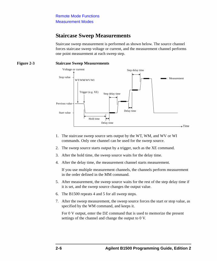
Remote Mode FunctionsMeasurement Modes
Staircase Sweep MeasurementsStaircase sweep measurement is performed as shown below. The source channel forces staircase sweep voltage or current, and the measurement channel performs one point measurement at each sweep step.
Figure 2-3 Staircase Sweep Measurements
1. The staircase sweep source sets output by the WT, WM, and WV or WI commands. Only one channel can be used for the sweep source.
2. The sweep source starts output by a trigger, such as the XE command.
3. After the hold time, the sweep source waits for the delay time.
4. After the delay time, the measurement channel starts measurement.
If you use multiple measurement channels, the channels perform measurement in the order defined in the MM command.
5. After measurement, the sweep source waits for the rest of the step delay time if it is set, and the sweep source changes the output value.
6. The B1500 repeats 4 and 5 for all sweep steps.
7. After the sweep measurement, the sweep source forces the start or stop value, as specified by the WM command, and keeps it.
For 0 V output, enter the DZ command that is used to memorize the present settings of the channel and change the output to 0 V.
Voltage or current
Stop value
Start value
Previous value
Time
: Measurement
Hold time
Step delay time
Trigger (e.g. XE)
WT/WM/WV/WI
Delay time
Step delay time
Delay time
2-6 Agilent B1500 Programming Guide, Edition 2
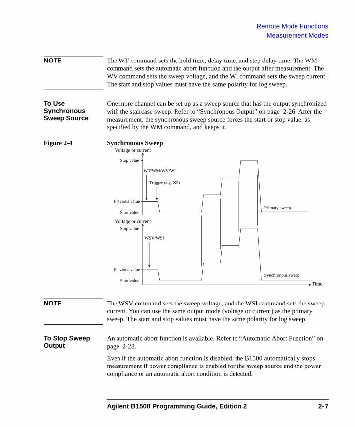
Remote Mode FunctionsMeasurement Modes
NOTE The WT command sets the hold time, delay time, and step delay time. The WM command sets the automatic abort function and the output after measurement. The WV command sets the sweep voltage, and the WI command sets the sweep current. The start and stop values must have the same polarity for log sweep.
To Use Synchronous Sweep Source
One more channel can be set up as a sweep source that has the output synchronized with the staircase sweep. Refer to “Synchronous Output” on page 2-26. After the measurement, the synchronous sweep source forces the start or stop value, as specified by the WM command, and keeps it.
Figure 2-4 Synchronous Sweep
NOTE The WSV command sets the sweep voltage, and the WSI command sets the sweep current. You can use the same output mode (voltage or current) as the primary sweep. The start and stop values must have the same polarity for log sweep.
To Stop Sweep Output
An automatic abort function is available. Refer to “Automatic Abort Function” on page 2-28.
Even if the automatic abort function is disabled, the B1500 automatically stops measurement if power compliance is enabled for the sweep source and the power compliance or an automatic abort condition is detected.
Voltage or current
Start valueTime
Stop value
Primary sweep
Synchronous sweepPrevious value
Trigger (e.g. XE)
WT/WM/WV/WI
WSV/WSI
Voltage or current
Start value
Stop value
Previous value
Agilent B1500 Programming Guide, Edition 2 2-7
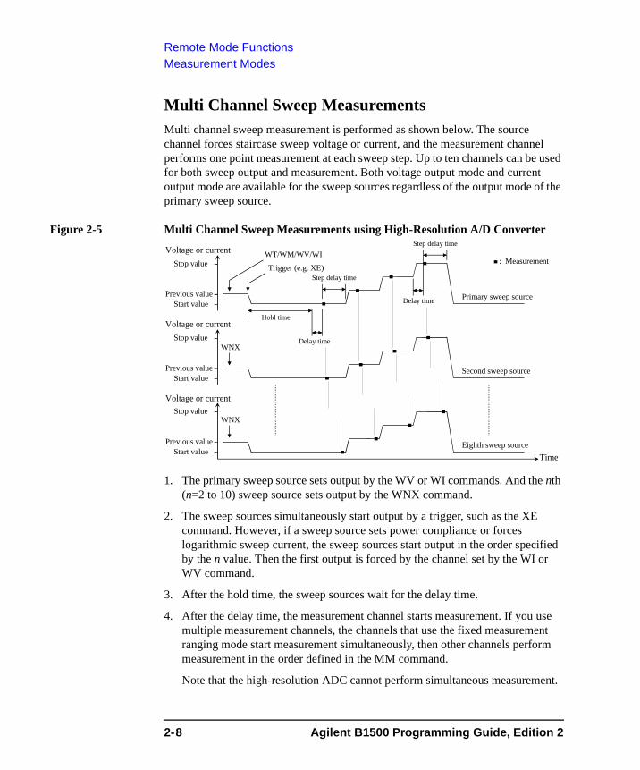
Remote Mode FunctionsMeasurement Modes
Multi Channel Sweep MeasurementsMulti channel sweep measurement is performed as shown below. The source channel forces staircase sweep voltage or current, and the measurement channel performs one point measurement at each sweep step. Up to ten channels can be used for both sweep output and measurement. Both voltage output mode and current output mode are available for the sweep sources regardless of the output mode of the primary sweep source.
Figure 2-5 Multi Channel Sweep Measurements using High-Resolution A/D Converter
1. The primary sweep source sets output by the WV or WI commands. And the nth (n=2 to 10) sweep source sets output by the WNX command.
2. The sweep sources simultaneously start output by a trigger, such as the XE command. However, if a sweep source sets power compliance or forces logarithmic sweep current, the sweep sources start output in the order specified by the n value. Then the first output is forced by the channel set by the WI or WV command.
3. After the hold time, the sweep sources wait for the delay time.
4. After the delay time, the measurement channel starts measurement. If you use multiple measurement channels, the channels that use the fixed measurement ranging mode start measurement simultaneously, then other channels perform measurement in the order defined in the MM command.
Note that the high-resolution ADC cannot perform simultaneous measurement.
Trigger (e.g. XE)
WT/WM/WV/WI
Voltage or currentStop value
Start valuePrevious value
Time
: Measurement
Hold time
Delay timeStop value
Start valuePrevious value
Voltage or current
Stop value
Start valuePrevious value
Voltage or current
WNX
WNX
Primary sweep source
Second sweep source
Eighth sweep source
Step delay time
Step delay time
Delay time
2-8 Agilent B1500 Programming Guide, Edition 2
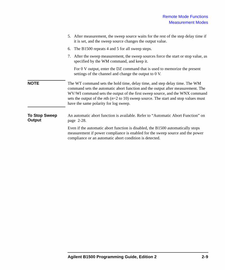
Remote Mode FunctionsMeasurement Modes
5. After measurement, the sweep source waits for the rest of the step delay time if it is set, and the sweep source changes the output value.
6. The B1500 repeats 4 and 5 for all sweep steps.
7. After the sweep measurement, the sweep sources force the start or stop value, as specified by the WM command, and keep it.
For 0 V output, enter the DZ command that is used to memorize the present settings of the channel and change the output to 0 V.
NOTE The WT command sets the hold time, delay time, and step delay time. The WM command sets the automatic abort function and the output after measurement. The WV/WI command sets the output of the first sweep source, and the WNX command sets the output of the nth (n=2 to 10) sweep source. The start and stop values must have the same polarity for log sweep.
To Stop Sweep Output
An automatic abort function is available. Refer to “Automatic Abort Function” on page 2-28.
Even if the automatic abort function is disabled, the B1500 automatically stops measurement if power compliance is enabled for the sweep source and the power compliance or an automatic abort condition is detected.
Agilent B1500 Programming Guide, Edition 2 2-9
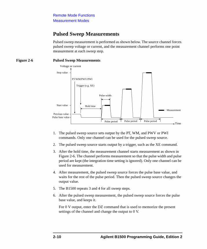
Remote Mode FunctionsMeasurement Modes
Pulsed Sweep MeasurementsPulsed sweep measurement is performed as shown below. The source channel forces pulsed sweep voltage or current, and the measurement channel performs one point measurement at each sweep step.
Figure 2-6 Pulsed Sweep Measurements
1. The pulsed sweep source sets output by the PT, WM, and PWV or PWI commands. Only one channel can be used for the pulsed sweep source.
2. The pulsed sweep source starts output by a trigger, such as the XE command.
3. After the hold time, the measurement channel starts measurement as shown in Figure 2-6. The channel performs measurement so that the pulse width and pulse period are kept (the integration time setting is ignored). Only one channel can be used for measurement.
4. After measurement, the pulsed sweep source forces the pulse base value, and waits for the rest of the pulse period. Then the pulsed sweep source changes the output value.
5. The B1500 repeats 3 and 4 for all sweep steps.
6. After the pulsed sweep measurement, the pulsed sweep source forces the pulse base value, and keeps it.
For 0 V output, enter the DZ command that is used to memorize the present settings of the channel and change the output to 0 V.
Voltage or current
Stop value
Start value
Previous value
Time
: MeasurementHold time
Pulse period
Trigger (e.g. XE)
PT/WM/PWV/PWI
Pulse base value
Pulse width
Pulse period Pulse period
2-10 Agilent B1500 Programming Guide, Edition 2
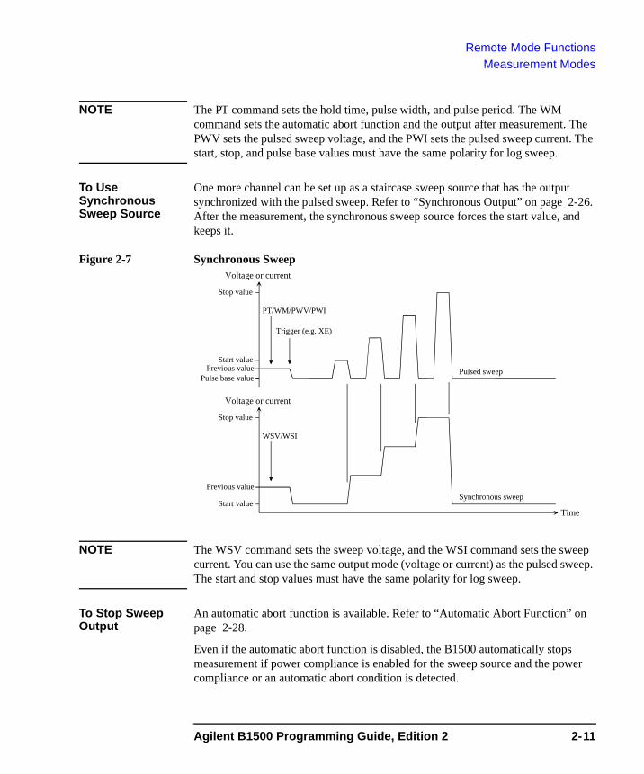
Remote Mode FunctionsMeasurement Modes
NOTE The PT command sets the hold time, pulse width, and pulse period. The WM command sets the automatic abort function and the output after measurement. The PWV sets the pulsed sweep voltage, and the PWI sets the pulsed sweep current. The start, stop, and pulse base values must have the same polarity for log sweep.
To Use Synchronous Sweep Source
One more channel can be set up as a staircase sweep source that has the output synchronized with the pulsed sweep. Refer to “Synchronous Output” on page 2-26. After the measurement, the synchronous sweep source forces the start value, and keeps it.
Figure 2-7 Synchronous Sweep
NOTE The WSV command sets the sweep voltage, and the WSI command sets the sweep current. You can use the same output mode (voltage or current) as the pulsed sweep. The start and stop values must have the same polarity for log sweep.
To Stop Sweep Output
An automatic abort function is available. Refer to “Automatic Abort Function” on page 2-28.
Even if the automatic abort function is disabled, the B1500 automatically stops measurement if power compliance is enabled for the sweep source and the power compliance or an automatic abort condition is detected.
Voltage or current
Start valueTime
Stop value
Pulse base value
Stop value
Synchronous sweep
Pulsed sweep
Previous value
Trigger (e.g. XE)
PT/WM/PWV/PWI
WSV/WSI
Start valuePrevious value
Voltage or current
Agilent B1500 Programming Guide, Edition 2 2-11
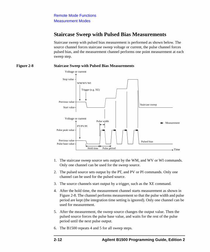
Remote Mode FunctionsMeasurement Modes
Staircase Sweep with Pulsed Bias MeasurementsStaircase sweep with pulsed bias measurement is performed as shown below. The source channel forces staircase sweep voltage or current, the pulse channel forces pulsed bias, and the measurement channel performs one point measurement at each sweep step.
Figure 2-8 Staircase Sweep with Pulsed Bias Measurements
1. The staircase sweep source sets output by the WM, and WV or WI commands. Only one channel can be used for the sweep source.
2. The pulsed source sets output by the PT, and PV or PI commands. Only one channel can be used for the pulsed source.
3. The source channels start output by a trigger, such as the XE command.
4. After the hold time, the measurement channel starts measurement as shown in Figure 2-8. The channel performs measurement so that the pulse width and pulse period are kept (the integration time setting is ignored). Only one channel can be used for measurement.
5. After the measurement, the sweep source changes the output value. Then the pulsed source forces the pulse base value, and waits for the rest of the pulse period until the next pulse output.
6. The B1500 repeats 4 and 5 for all sweep steps.
Voltage or current
Start value
Time
Stop value
Pulse base value
Pulse peak value
Pulsed bias
Staircase sweep
Previous value
Trigger (e.g. XE)
WM/WV/WI
PT/PV/PI
Previous value
Voltage or current: Measurement
Hold time
Pulse width
Pulse period
2-12 Agilent B1500 Programming Guide, Edition 2
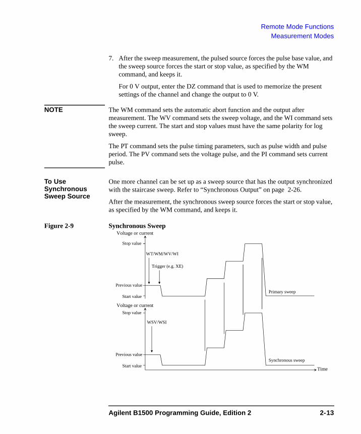
Remote Mode FunctionsMeasurement Modes
7. After the sweep measurement, the pulsed source forces the pulse base value, and the sweep source forces the start or stop value, as specified by the WM command, and keeps it.
For 0 V output, enter the DZ command that is used to memorize the present settings of the channel and change the output to 0 V.
NOTE The WM command sets the automatic abort function and the output after measurement. The WV command sets the sweep voltage, and the WI command sets the sweep current. The start and stop values must have the same polarity for log sweep.
The PT command sets the pulse timing parameters, such as pulse width and pulse period. The PV command sets the voltage pulse, and the PI command sets current pulse.
To Use Synchronous Sweep Source
One more channel can be set up as a sweep source that has the output synchronized with the staircase sweep. Refer to “Synchronous Output” on page 2-26.
After the measurement, the synchronous sweep source forces the start or stop value, as specified by the WM command, and keeps it.
Figure 2-9 Synchronous SweepVoltage or current
Start valueTime
Stop value
Primary sweep
Synchronous sweepPrevious value
Trigger (e.g. XE)
WT/WM/WV/WI
WSV/WSI
Voltage or current
Start value
Stop value
Previous value
Agilent B1500 Programming Guide, Edition 2 2-13
Remote Mode FunctionsMeasurement Modes
NOTE The WSV command sets the sweep voltage, and the WSI command sets the sweep current. You can use the same output mode (voltage or current) as the primary sweep. The start and stop values must have the same polarity for log sweep.
To Stop Sweep Output
An automatic abort function is available. Refer to “Automatic Abort Function” on page 2-28.
Even if the automatic abort function is disabled, the B1500 automatically stops measurement if power compliance is enabled for the sweep source and the power compliance or an automatic abort condition is detected.
2-14 Agilent B1500 Programming Guide, Edition 2
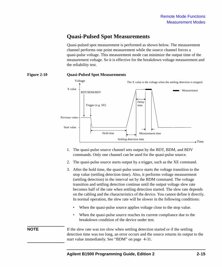
Remote Mode FunctionsMeasurement Modes
Quasi-Pulsed Spot MeasurementsQuasi-pulsed spot measurement is performed as shown below. The measurement channel performs one point measurement while the source channel forces a quasi-pulse voltage. This measurement mode can minimize the output time of the measurement voltage. So it is effective for the breakdown voltage measurement and the reliability test.
Figure 2-10 Quasi-Pulsed Spot Measurements
1. The quasi-pulse source channel sets output by the BDT, BDM, and BDV commands. Only one channel can be used for the quasi-pulse source.
2. The quasi-pulse source starts output by a trigger, such as the XE command.
3. After the hold time, the quasi-pulse source starts the voltage transition to the stop value (settling detection time). Also, it performs voltage measurement (settling detection) in the interval set by the BDM command. The voltage transition and settling detection continue until the output voltage slew rate becomes half of the rate when settling detection started. The slew rate depends on the cabling and the characteristics of the device. You cannot define it directly. In normal operation, the slew rate will be slower in the following conditions:
• When the quasi-pulse source applies voltage close to the stop value.
• When the quasi-pulse source reaches its current compliance due to the breakdown condition of the device under test.
NOTE If the slew rate was too slow when settling detection started or if the settling detection time was too long, an error occurs and the source returns its output to the start value immediately. See “BDM” on page 4-31.
Voltage
Measurement time
X value
Start value
Previous value
Time
: Measurement
Hold time
DelaytimeTrigger (e.g. XE)
BDT/BDM/BDV
Settling detection time
The X value is the voltage when the settling detection is stopped.
Agilent B1500 Programming Guide, Edition 2 2-15

Remote Mode FunctionsMeasurement Modes
4. After the settling detection stops, the quasi-pulse source keeps the output.
5. After the delay time, the measurement channel starts measurement.Only one channel can be used for measurement.
6. After measurement, the quasi-pulse source immediately returns the output to the start value and keeps it.
For 0 V output, enter the DZ command that is used to memorize the present settings of the channel and change the output to 0 V.
NOTE If there is noise or skew on the output voltage, settling detection might stop at an unexpected voltage.
NOTE The BDT command sets the hold time and delay time, and the BDM command sets the settling detection interval and measurement mode (voltage or current); the BDV command sets the output. Also |start-stop| must be 10 V or more.
2-16 Agilent B1500 Programming Guide, Edition 2
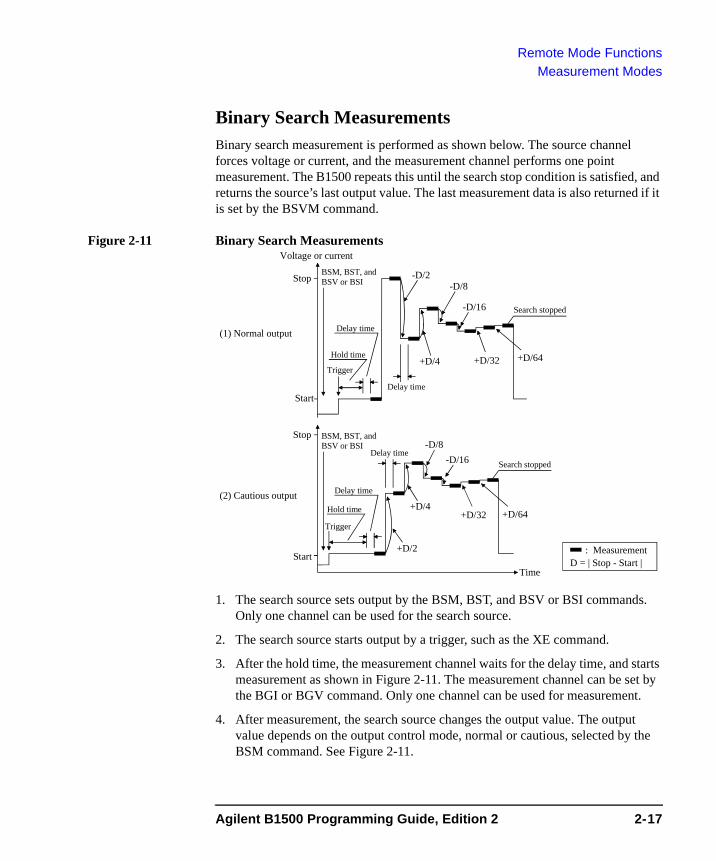
Remote Mode FunctionsMeasurement Modes
Binary Search MeasurementsBinary search measurement is performed as shown below. The source channel forces voltage or current, and the measurement channel performs one point measurement. The B1500 repeats this until the search stop condition is satisfied, and returns the source’s last output value. The last measurement data is also returned if it is set by the BSVM command.
Figure 2-11 Binary Search Measurements
1. The search source sets output by the BSM, BST, and BSV or BSI commands. Only one channel can be used for the search source.
2. The search source starts output by a trigger, such as the XE command.
3. After the hold time, the measurement channel waits for the delay time, and starts measurement as shown in Figure 2-11. The measurement channel can be set by the BGI or BGV command. Only one channel can be used for measurement.
4. After measurement, the search source changes the output value. The output value depends on the output control mode, normal or cautious, selected by the BSM command. See Figure 2-11.
Start
Stop
D = | Stop - Start |
+D/4
-D/2-D/8
-D/16
(1) Normal output
Search stopped
+D/32 +D/64
: MeasurementStart
Stop
+D/4
+D/2
-D/8-D/16
(2) Cautious output
Search stopped
+D/32 +D/64
Time
Voltage or current
Hold time
Delay time
Hold time
Delay time
Delay time
Delay time
Trigger
Trigger
BSM, BST, and BSV or BSI
BSM, BST, and BSV or BSI
Agilent B1500 Programming Guide, Edition 2 2-17
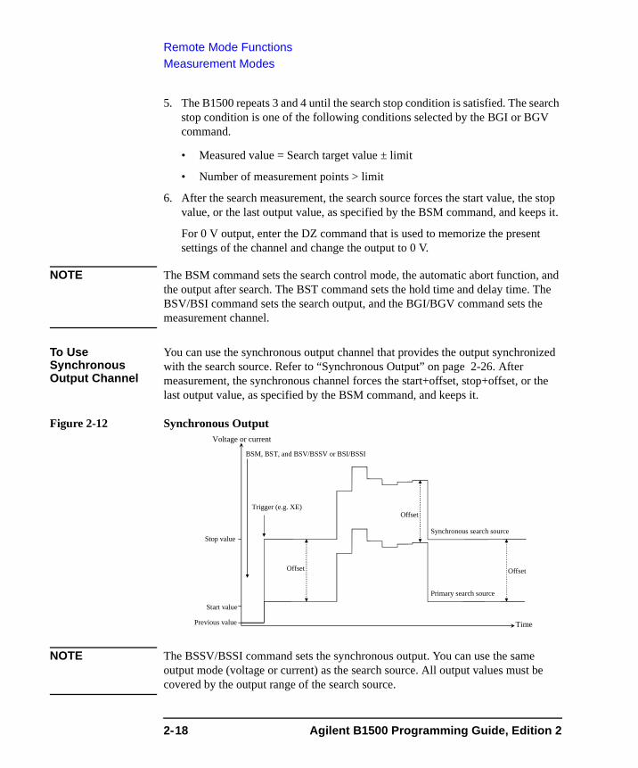
Remote Mode FunctionsMeasurement Modes
5. The B1500 repeats 3 and 4 until the search stop condition is satisfied. The search stop condition is one of the following conditions selected by the BGI or BGV command.
• Measured value = Search target value ± limit
• Number of measurement points > limit
6. After the search measurement, the search source forces the start value, the stop value, or the last output value, as specified by the BSM command, and keeps it.
For 0 V output, enter the DZ command that is used to memorize the present settings of the channel and change the output to 0 V.
NOTE The BSM command sets the search control mode, the automatic abort function, and the output after search. The BST command sets the hold time and delay time. The BSV/BSI command sets the search output, and the BGI/BGV command sets the measurement channel.
To Use Synchronous Output Channel
You can use the synchronous output channel that provides the output synchronized with the search source. Refer to “Synchronous Output” on page 2-26. After measurement, the synchronous channel forces the start+offset, stop+offset, or the last output value, as specified by the BSM command, and keeps it.
Figure 2-12 Synchronous Output
NOTE The BSSV/BSSI command sets the synchronous output. You can use the same output mode (voltage or current) as the search source. All output values must be covered by the output range of the search source.
Voltage or current
Start value
Time
Stop value
Primary search source
Synchronous search source
Previous value
Trigger (e.g. XE)
BSM, BST, and BSV/BSSV or BSI/BSSI
Offset
Offset Offset
2-18 Agilent B1500 Programming Guide, Edition 2
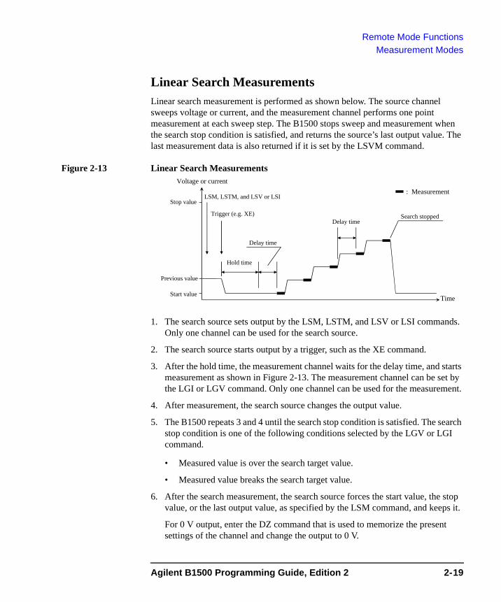
Remote Mode FunctionsMeasurement Modes
Linear Search MeasurementsLinear search measurement is performed as shown below. The source channel sweeps voltage or current, and the measurement channel performs one point measurement at each sweep step. The B1500 stops sweep and measurement when the search stop condition is satisfied, and returns the source’s last output value. The last measurement data is also returned if it is set by the LSVM command.
Figure 2-13 Linear Search Measurements
1. The search source sets output by the LSM, LSTM, and LSV or LSI commands. Only one channel can be used for the search source.
2. The search source starts output by a trigger, such as the XE command.
3. After the hold time, the measurement channel waits for the delay time, and starts measurement as shown in Figure 2-13. The measurement channel can be set by the LGI or LGV command. Only one channel can be used for the measurement.
4. After measurement, the search source changes the output value.
5. The B1500 repeats 3 and 4 until the search stop condition is satisfied. The search stop condition is one of the following conditions selected by the LGV or LGI command.
• Measured value is over the search target value.
• Measured value breaks the search target value.
6. After the search measurement, the search source forces the start value, the stop value, or the last output value, as specified by the LSM command, and keeps it.
For 0 V output, enter the DZ command that is used to memorize the present settings of the channel and change the output to 0 V.
Voltage or current
Start valueTime
Stop value
Previous value
Trigger (e.g. XE)
LSM, LSTM, and LSV or LSI: Measurement
Hold time
Delay time
Search stoppedDelay time
Agilent B1500 Programming Guide, Edition 2 2-19
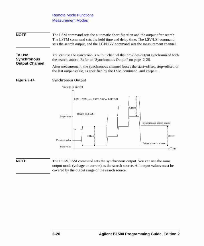
Remote Mode FunctionsMeasurement Modes
NOTE The LSM command sets the automatic abort function and the output after search. The LSTM command sets the hold time and delay time. The LSV/LSI command sets the search output, and the LGI/LGV command sets the measurement channel.
To Use Synchronous Output Channel
You can use the synchronous output channel that provides output synchronized with the search source. Refer to “Synchronous Output” on page 2-26.
After measurement, the synchronous channel forces the start+offset, stop+offset, or the last output value, as specified by the LSM command, and keeps it.
Figure 2-14 Synchronous Output
NOTE The LSSV/LSSI command sets the synchronous output. You can use the same output mode (voltage or current) as the search source. All output values must be covered by the output range of the search source.
Voltage or current
Start valueTime
Stop value
Primary search source
Synchronous search source
Previous value
Trigger (e.g. XE)
LSM, LSTM, and LSV/LSSV or LSI/LSSI
Offset
Offset Offset
2-20 Agilent B1500 Programming Guide, Edition 2
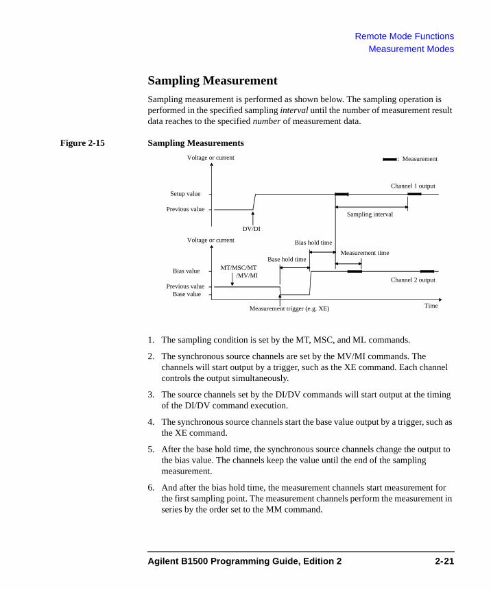
Remote Mode FunctionsMeasurement Modes
Sampling MeasurementSampling measurement is performed as shown below. The sampling operation is performed in the specified sampling interval until the number of measurement result data reaches to the specified number of measurement data.
Figure 2-15 Sampling Measurements
1. The sampling condition is set by the MT, MSC, and ML commands.
2. The synchronous source channels are set by the MV/MI commands. The channels will start output by a trigger, such as the XE command. Each channel controls the output simultaneously.
3. The source channels set by the DI/DV commands will start output at the timing of the DI/DV command execution.
4. The synchronous source channels start the base value output by a trigger, such as the XE command.
5. After the base hold time, the synchronous source channels change the output to the bias value. The channels keep the value until the end of the sampling measurement.
6. And after the bias hold time, the measurement channels start measurement for the first sampling point. The measurement channels perform the measurement in series by the order set to the MM command.
Voltage or current
DV/DI
MT/MSC/MT/MV/MI
Measurement trigger (e.g. XE)
Measurement time
Channel 1 output
Channel 2 output
Setup value
Previous value
Bias value
Previous value
Voltage or current
Time
: Measurement
Base hold time
Bias hold time
Base value
Sampling interval
Agilent B1500 Programming Guide, Edition 2 2-21
Remote Mode FunctionsMeasurement Modes
7. After that, the following operation is repeated with the specified time interval.
• Measurement channels start measurement if they are ready to measure.
• Measurement channels keep the condition if they are busy.
This operation is repeated until the number of measurement result data reaches to the specified number of measurement data.
For the linear sampling with interval < 2 ms, if the total measurement time runs over the specified time interval × number, the sampling measurement will be stopped even if the number of measurement result data is less than the specified number.
For the log sampling, the B1500A holds only the data that can be plotted on the log scale in the same distance as close as possible. Only the held data is counted in the number of measurement result data.
8. After the sampling measurement, the synchronous source channel set by the MI/MV command forces the base or bias value specified by the MSC command.
9. The source channel set by the DV or DI command continues the source output.
For 0 V output, enter the DZ command that is used to memorize the present settings of the channel and change the output to 0 V.
NOTE The MT command sets the bias hold time, sampling interval, number of samples, and base hold time.
The MSC command sets the automatic abort function and the output after measurement.
The ML command sets the linear sampling mode or the log sampling mode.
The MV and MI commands set the synchronous voltage source and current source respectively.
The MCC command clears the MV and MI command setting.
To Stop Output An automatic abort function is available. Refer to “Automatic Abort Function” on page 2-28.
2-22 Agilent B1500 Programming Guide, Edition 2
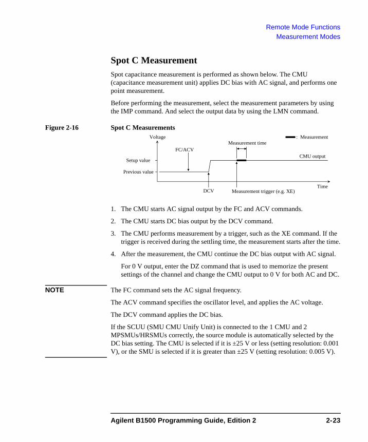
Remote Mode FunctionsMeasurement Modes
Spot C MeasurementSpot capacitance measurement is performed as shown below. The CMU (capacitance measurement unit) applies DC bias with AC signal, and performs one point measurement.
Before performing the measurement, select the measurement parameters by using the IMP command. And select the output data by using the LMN command.
Figure 2-16 Spot C Measurements
1. The CMU starts AC signal output by the FC and ACV commands.
2. The CMU starts DC bias output by the DCV command.
3. The CMU performs measurement by a trigger, such as the XE command. If the trigger is received during the settling time, the measurement starts after the time.
4. After the measurement, the CMU continue the DC bias output with AC signal.
For 0 V output, enter the DZ command that is used to memorize the present settings of the channel and change the CMU output to 0 V for both AC and DC.
NOTE The FC command sets the AC signal frequency.
The ACV command specifies the oscillator level, and applies the AC voltage.
The DCV command applies the DC bias.
If the SCUU (SMU CMU Unify Unit) is connected to the 1 CMU and 2 MPSMUs/HRSMUs correctly, the source module is automatically selected by the DC bias setting. The CMU is selected if it is ±25 V or less (setting resolution: 0.001 V), or the SMU is selected if it is greater than ±25 V (setting resolution: 0.005 V).
DCV Measurement trigger (e.g. XE)
Measurement time
CMU outputSetup value
Previous value
Voltage
Time
: Measurement
FC/ACV
Agilent B1500 Programming Guide, Edition 2 2-23
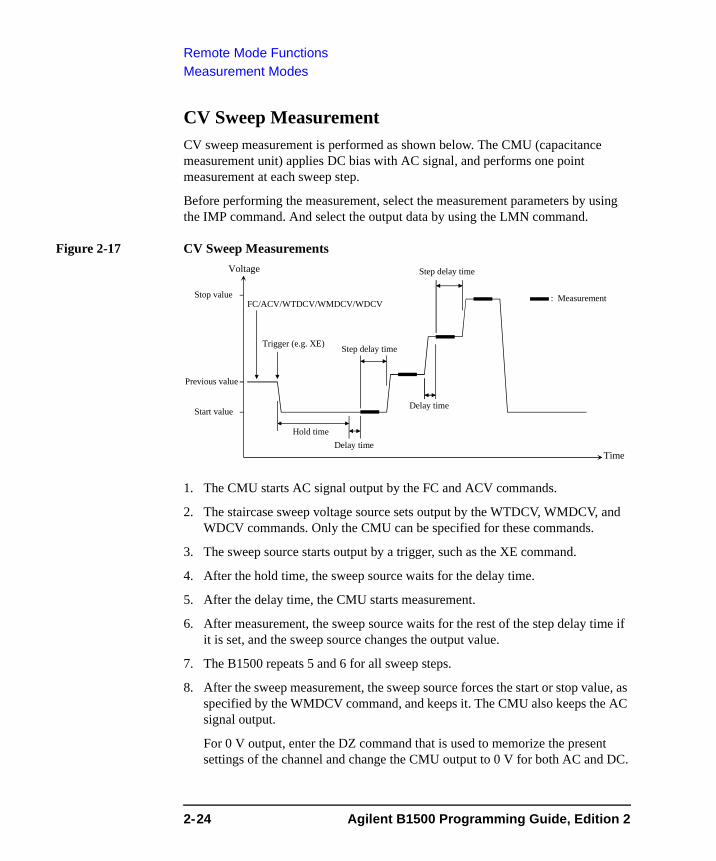
Remote Mode FunctionsMeasurement Modes
CV Sweep MeasurementCV sweep measurement is performed as shown below. The CMU (capacitance measurement unit) applies DC bias with AC signal, and performs one point measurement at each sweep step.
Before performing the measurement, select the measurement parameters by using the IMP command. And select the output data by using the LMN command.
Figure 2-17 CV Sweep Measurements
1. The CMU starts AC signal output by the FC and ACV commands.
2. The staircase sweep voltage source sets output by the WTDCV, WMDCV, and WDCV commands. Only the CMU can be specified for these commands.
3. The sweep source starts output by a trigger, such as the XE command.
4. After the hold time, the sweep source waits for the delay time.
5. After the delay time, the CMU starts measurement.
6. After measurement, the sweep source waits for the rest of the step delay time if it is set, and the sweep source changes the output value.
7. The B1500 repeats 5 and 6 for all sweep steps.
8. After the sweep measurement, the sweep source forces the start or stop value, as specified by the WMDCV command, and keeps it. The CMU also keeps the AC signal output.
For 0 V output, enter the DZ command that is used to memorize the present settings of the channel and change the CMU output to 0 V for both AC and DC.
Voltage
Stop value
Start value
Previous value
Time
: Measurement
Hold time
Step delay time
Trigger (e.g. XE)
FC/ACV/WTDCV/WMDCV/WDCV
Delay time
Step delay time
Delay time
2-24 Agilent B1500 Programming Guide, Edition 2
Remote Mode FunctionsMeasurement Modes
NOTE The FC command sets the AC signal frequency.
The ACV command specifies the oscillator level, and applies the AC voltage.
The WTDCV command sets the hold time, delay time, and step delay time.
The WMDCV command sets the automatic abort function and the output after measurement.
The WDCV command sets the sweep voltage. The start and stop values must have the same polarity for log sweep.
If the SCUU (SMU CMU Unify Unit) is connected to the 1 CMU and 2 MPSMUs/HRSMUs correctly, the source module is automatically selected by the sweep range (from start to stop). The CMU is selected if it is ±25 V or less (setting resolution: 0.001 V), or the SMU is selected if it is greater than ±25 V (setting resolution: 0.005 V).
To Stop Sweep Output
An automatic abort function is available. Refer to “Automatic Abort Function” on page 2-28.
Agilent B1500 Programming Guide, Edition 2 2-25
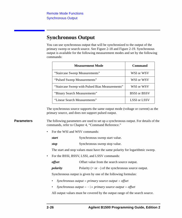
Remote Mode FunctionsSynchronous Output
Synchronous OutputYou can use synchronous output that will be synchronized to the output of the primary sweep or search source. See Figure 2-18 and Figure 2-19. Synchronous output is available for the following measurement modes and set by the following commands:
The synchronous source supports the same output mode (voltage or current) as the primary source, and does not support pulsed output.
Parameters The following parameters are used to set up a synchronous output. For details of the commands, refer to Chapter 4, “Command Reference.”
• For the WSI and WSV commands:
start Synchronous sweep start value.
stop Synchronous sweep stop value.
The start and stop values must have the same polarity for logarithmic sweep.
• For the BSSI, BSSV, LSSI, and LSSV commands:
offset Offset value from the search source output.
polarity Polarity (+ or -) of the synchronous source output.
Synchronous output is given by one of the following formulas:
• Synchronous output = primary source output + offset
• Synchronous output = -1× primary source output + offset
All output values must be covered by the output range of the search source.
Measurement Mode Command
“Staircase Sweep Measurements” WSI or WSV
“Pulsed Sweep Measurements” WSI or WSV
“Staircase Sweep with Pulsed Bias Measurements” WSI or WSV
“Binary Search Measurements” BSSI or BSSV
“Linear Search Measurements” LSSI or LSSV
2-26 Agilent B1500 Programming Guide, Edition 2
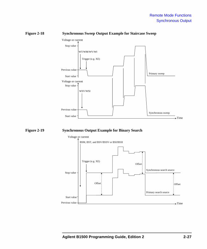
Remote Mode FunctionsSynchronous Output
Figure 2-18 Synchronous Sweep Output Example for Staircase Sweep
Figure 2-19 Synchronous Output Example for Binary Search
Voltage or current
Start valueTime
Stop value
Primary sweep
Synchronous sweepPrevious value
Trigger (e.g. XE)
WT/WM/WV/WI
WSV/WSI
Voltage or current
Start value
Stop value
Previous value
Voltage or current
Start value
Time
Stop value
Primary search source
Synchronous search source
Previous value
Trigger (e.g. XE)
BSM, BST, and BSV/BSSV or BSI/BSSI
Offset
Offset Offset
Agilent B1500 Programming Guide, Edition 2 2-27
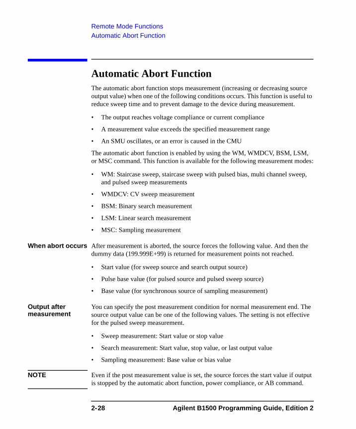
Remote Mode FunctionsAutomatic Abort Function
Automatic Abort FunctionThe automatic abort function stops measurement (increasing or decreasing source output value) when one of the following conditions occurs. This function is useful to reduce sweep time and to prevent damage to the device during measurement.
• The output reaches voltage compliance or current compliance
• A measurement value exceeds the specified measurement range
• An SMU oscillates, or an error is caused in the CMU
The automatic abort function is enabled by using the WM, WMDCV, BSM, LSM, or MSC command. This function is available for the following measurement modes:
• WM: Staircase sweep, staircase sweep with pulsed bias, multi channel sweep, and pulsed sweep measurements
• WMDCV: CV sweep measurement
• BSM: Binary search measurement
• LSM: Linear search measurement
• MSC: Sampling measurement
When abort occurs After measurement is aborted, the source forces the following value. And then the dummy data (199.999E+99) is returned for measurement points not reached.
• Start value (for sweep source and search output source)
• Pulse base value (for pulsed source and pulsed sweep source)
• Base value (for synchronous source of sampling measurement)
Output after measurement
You can specify the post measurement condition for normal measurement end. The source output value can be one of the following values. The setting is not effective for the pulsed sweep measurement.
• Sweep measurement: Start value or stop value
• Search measurement: Start value, stop value, or last output value
• Sampling measurement: Base value or bias value
NOTE Even if the post measurement value is set, the source forces the start value if output is stopped by the automatic abort function, power compliance, or AB command.
2-28 Agilent B1500 Programming Guide, Edition 2
Remote Mode FunctionsParallel Measurement Function
Parallel Measurement FunctionThe following measurement modes enable the parallel measurement (simultaneous measurement) by using the multiple measurement channels.
• Spot measurement (MM 1,chnum,chnum, . . . ,chnum)
• Staircase sweep measurement (MM 2,chnum,chnum, . . . ,chnum)
where, chnum is the slot number where the measurement channel (SMU) has been installed. 1 to 10 (integer) are available.
To Enable Parallel MeasurementExecute the following command to enable the parallel measurement function.
PAD 1
To Set Measurement ChannelsThe following conditions must be satisfied for the measurement channels to perform the parallel measurements.
• Use the high speed A/D converter
AAD chnum,0 command
• Use the fixed ranging for the measurement
RI chnum,range command (for current measurement)
RV chnum,range command (for voltage measurement)
Enter the negative value for range to use the fixed ranging.
Agilent B1500 Programming Guide, Edition 2 2-29
Remote Mode FunctionsProgram Memory
Program MemoryThe program memory is a volatile memory that is used to store command strings temporarily. The Agilent B1500 has a built-in program memory that can store 2,000 programs maximum, and a total of 40,000 commands.
The program memory can eliminate several processes in the program execution, such as transferring commands, checking command syntax, and converting commands to the internal codes. Thus, using the program memory speeds up program execution. If frequently used command strings are stored in the program memory, GPIB/computer activity is minimized.
Using Program MemoryYou can store, execute, read, and delete programs in the program memory as shown below. For details on each command, refer to Chapter 4, “Command Reference.”
To store programs Send the ST and END commands to store a program. The following procedure stores a program (program number n) in the program memory. A multiple command string is also available.
1. OUTPUT @B1500;”ST n”
where, n is the program number for the program now stored in the program memory. The value must be an integer, 1 to 2000.
2. OUTPUT @B1500;”XXXX”
where, XXXX must be the command you want to store in the program memory. Repeat this until all required commands are stored.
Table 2-1 lists the invalid commands for the program memory.
3. OUTPUT @B1500;”END”
NOTE The program must be complete and free of errors.
An error occurs if the program memory overflows while a program is being stored.
If you store a new program using an existing program number, the old program is deleted and the new program is stored.
2-30 Agilent B1500 Programming Guide, Edition 2
Remote Mode FunctionsProgram Memory
To call programs from a memory program
A memory program can invoke another memory program by storing the DO or RU command in the memory program. Up to eight levels of nesting are available. The first level is always the DO or RU command sent by the external computer.
To execute programs
Send the RU or DO command to execute the memory program.
• OUTPUT @B1500;”RU 1,5”
This example executes the programs numbered 1 through 5 sequentially. These programs must be stored in the memory.
• OUTPUT @B1500;”DO 1,2,3,4,5”
This example executes programs 1, 2, 3, 4, and 5 in this order. These programs must be stored in the memory. A maximum of eight numbers can be specified.
To use variables You can use variables in the memory programs. To enter the value to the variable, send the VAR command. If the variable is referred by multiple programs or commands, set or change the value carefully so that the program works fine without errors. Format of the variable is %tn (t: integer I or real R, n: integer, 1 to 99).
In the following example, the first line stores a program (program 99) which uses the %I50 variable. The second line enters 2 to %I50, and executes the program 99.
OUTPUT @B1500;”ST99;CN%I50;DV%I50,0,2;TI%I50;CL%I50;END”OUTPUT @B1500;”VAR0,50,2;DO99”
To read programs To read the program numbers of the memory programs, send the LST? command without a command parameter.
To read the contents of a memory program, send the LST? command with the program number as shown below. Up to 3000 commands can be read by one command execution.
OUTPUT @B1500;”LST? 100”
To delete programs
To delete all memory programs, send the SCR command without a parameter.
To delete a memory program, send the SCR command with the program number as shown below.
OUTPUT @B1500;”SCR 100”
NOTE Turning off the instrument also clears the program memory. The device clear and *RST commands do not clear the program memory.
Agilent B1500 Programming Guide, Edition 2 2-31
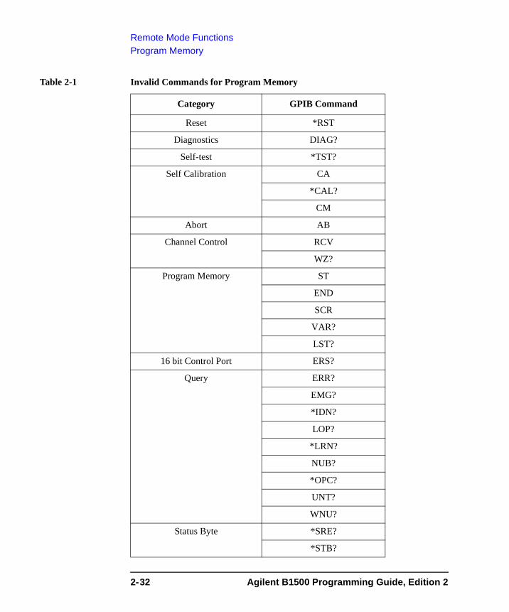
Remote Mode FunctionsProgram Memory
Table 2-1 Invalid Commands for Program Memory
Category GPIB Command
Reset *RST
Diagnostics DIAG?
Self-test *TST?
Self Calibration CA
*CAL?
CM
Abort AB
Channel Control RCV
WZ?
Program Memory ST
END
SCR
VAR?
LST?
16 bit Control Port ERS?
Query ERR?
EMG?
*IDN?
LOP?
*LRN?
NUB?
*OPC?
UNT?
WNU?
Status Byte *SRE?
*STB?
2-32 Agilent B1500 Programming Guide, Edition 2
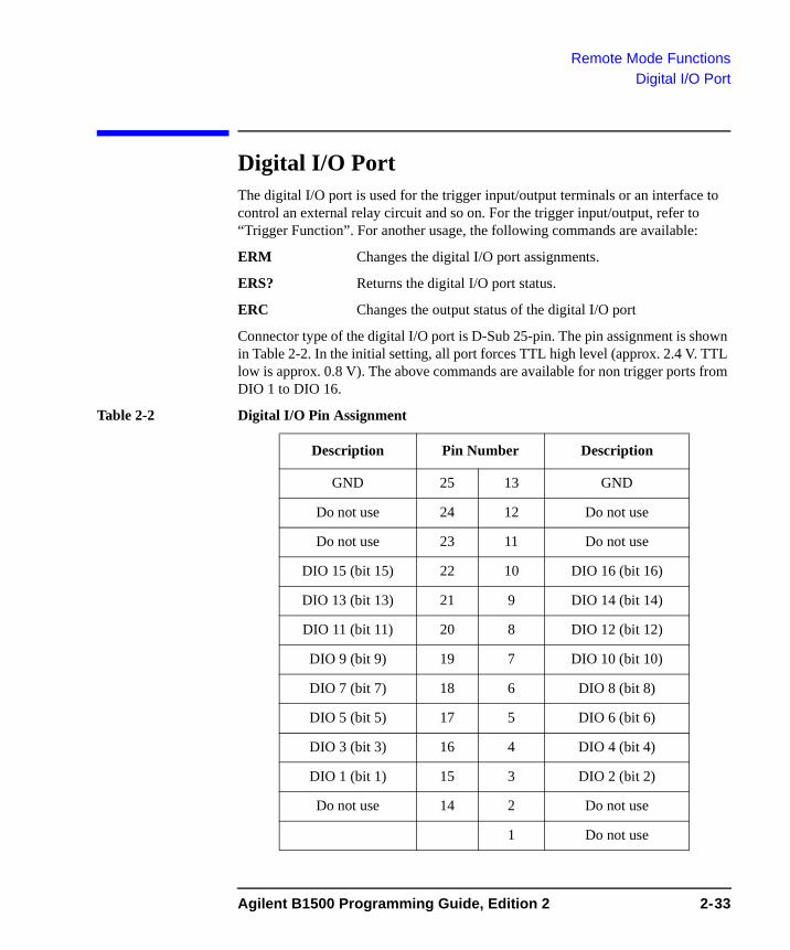
Remote Mode FunctionsDigital I/O Port
Digital I/O PortThe digital I/O port is used for the trigger input/output terminals or an interface to control an external relay circuit and so on. For the trigger input/output, refer to “Trigger Function”. For another usage, the following commands are available:
ERM Changes the digital I/O port assignments.
ERS? Returns the digital I/O port status.
ERC Changes the output status of the digital I/O port
Connector type of the digital I/O port is D-Sub 25-pin. The pin assignment is shown in Table 2-2. In the initial setting, all port forces TTL high level (approx. 2.4 V. TTL low is approx. 0.8 V). The above commands are available for non trigger ports from DIO 1 to DIO 16.
Table 2-2 Digital I/O Pin Assignment
Description Pin Number Description
GND 25 13 GND
Do not use 24 12 Do not use
Do not use 23 11 Do not use
DIO 15 (bit 15) 22 10 DIO 16 (bit 16)
DIO 13 (bit 13) 21 9 DIO 14 (bit 14)
DIO 11 (bit 11) 20 8 DIO 12 (bit 12)
DIO 9 (bit 9) 19 7 DIO 10 (bit 10)
DIO 7 (bit 7) 18 6 DIO 8 (bit 8)
DIO 5 (bit 5) 17 5 DIO 6 (bit 6)
DIO 3 (bit 3) 16 4 DIO 4 (bit 4)
DIO 1 (bit 1) 15 3 DIO 2 (bit 2)
Do not use 14 2 Do not use
1 Do not use
Agilent B1500 Programming Guide, Edition 2 2-33
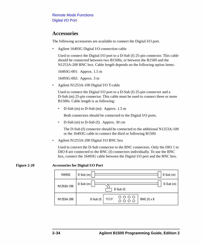
Remote Mode FunctionsDigital I/O Port
AccessoriesThe following accessories are available to connect the Digital I/O port.
• Agilent 16493G Digital I/O connection cable
Used to connect the Digital I/O port to a D-Sub (f) 25-pin connector. This cable should be connected between two B1500s, or between the B1500 and the N1253A-200 BNC box. Cable length depends on the following option items:
16493G-001: Approx. 1.5 m
16493G-002: Approx. 3 m
• Agilent N1253A-100 Digital I/O T-cable
Used to connect the Digital I/O port to a D-Sub (f) 25-pin connector and a D-Sub (m) 25-pin connector. This cable must be used to connect three or more B1500s. Cable length is as following:
• D-Sub (m) to D-Sub (m): Approx. 1.5 m
Both connectors should be connected to the Digital I/O ports.
• D-Sub (m) to D-Sub (f): Approx. 30 cm
The D-Sub (f) connector should be connected to the additional N1253A-100 or the 16493G cable to connect the third or following B1500.
• Agilent N1253A-200 Digital I/O BNC box
Used to convert the D-Sub connector to the BNC connectors. Only the DIO 1 to DIO 8 are connected to the BNC (f) connectors individually. To use the BNC box, connect the 16493G cable between the Digital I/O port and the BNC box.
Figure 2-20 Accessories for Digital I/O Port
D-Sub (m)
D-Sub (m)
D-Sub (m)
D-Sub (m)
D-Sub (f)
D-Sub (f)
N1253A-100
N1253A-200
16493G
BNC (f) x 8
2-34 Agilent B1500 Programming Guide, Edition 2
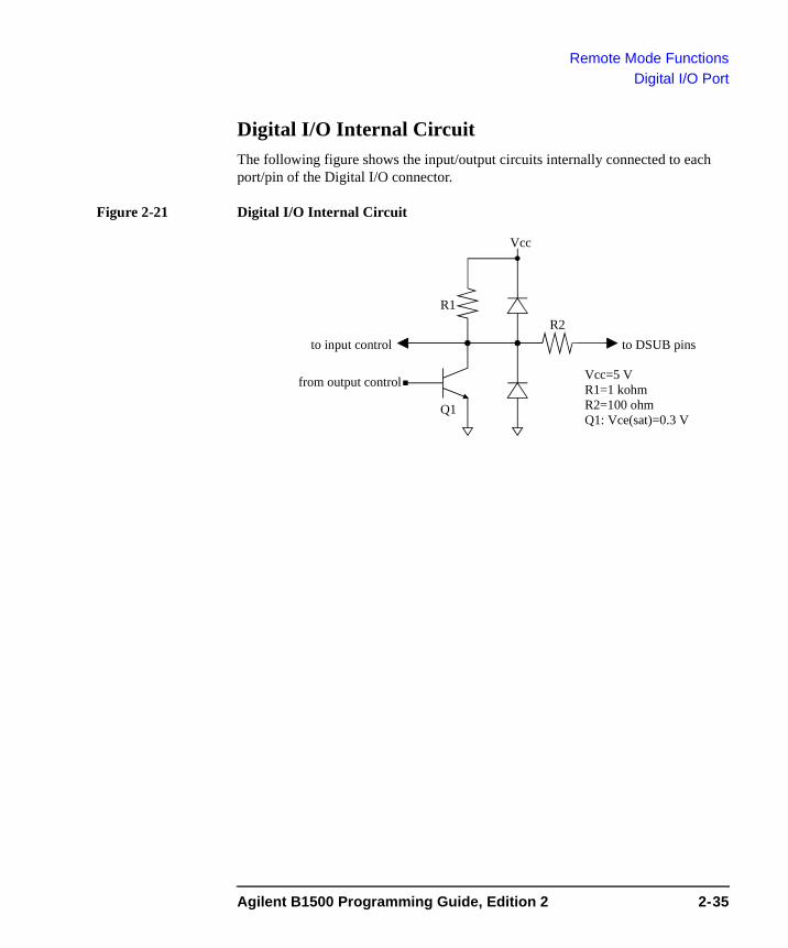
Remote Mode FunctionsDigital I/O Port
Digital I/O Internal CircuitThe following figure shows the input/output circuits internally connected to each port/pin of the Digital I/O connector.
Figure 2-21 Digital I/O Internal Circuit
Vcc
R2R1
Q1
to input control
from output control
to DSUB pins
Vcc=5 VR1=1 kohmR2=100 ohmQ1: Vce(sat)=0.3 V
Agilent B1500 Programming Guide, Edition 2 2-35
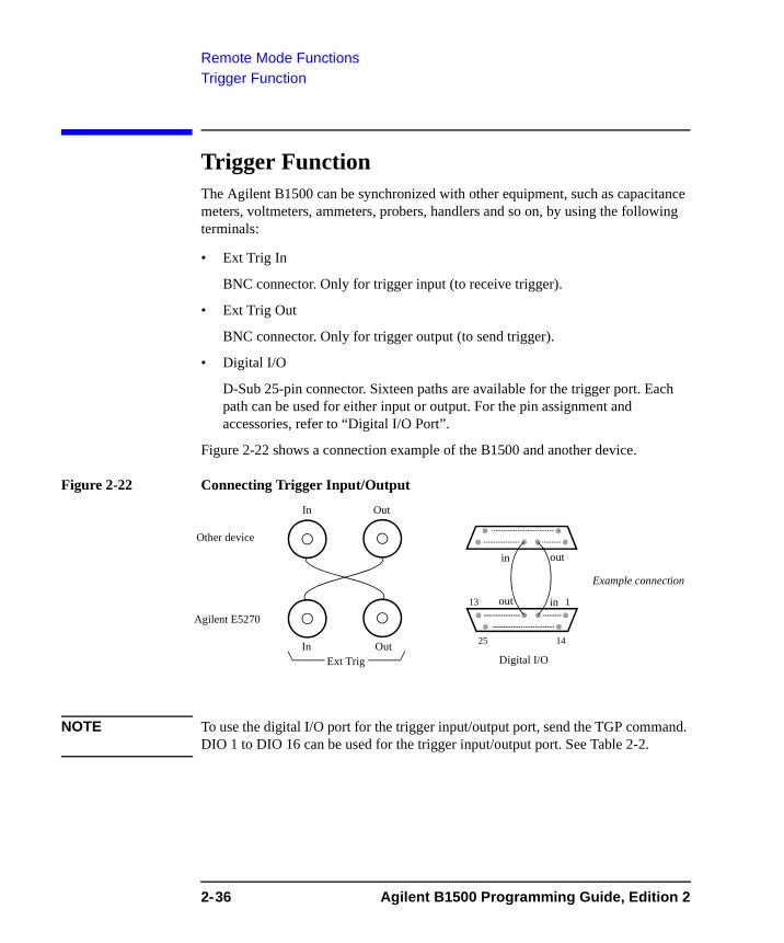
Remote Mode FunctionsTrigger Function
Trigger FunctionThe Agilent B1500 can be synchronized with other equipment, such as capacitance meters, voltmeters, ammeters, probers, handlers and so on, by using the following terminals:
• Ext Trig In
BNC connector. Only for trigger input (to receive trigger).
• Ext Trig Out
BNC connector. Only for trigger output (to send trigger).
• Digital I/O
D-Sub 25-pin connector. Sixteen paths are available for the trigger port. Each path can be used for either input or output. For the pin assignment and accessories, refer to “Digital I/O Port”.
Figure 2-22 shows a connection example of the B1500 and another device.
Figure 2-22 Connecting Trigger Input/Output
NOTE To use the digital I/O port for the trigger input/output port, send the TGP command. DIO 1 to DIO 16 can be used for the trigger input/output port. See Table 2-2.
Ext Trig
Agilent E5270
Other device
in
out
Digital I/O
out
in
Example connection
In Out
In Out
13 1
25 14
2-36 Agilent B1500 Programming Guide, Edition 2
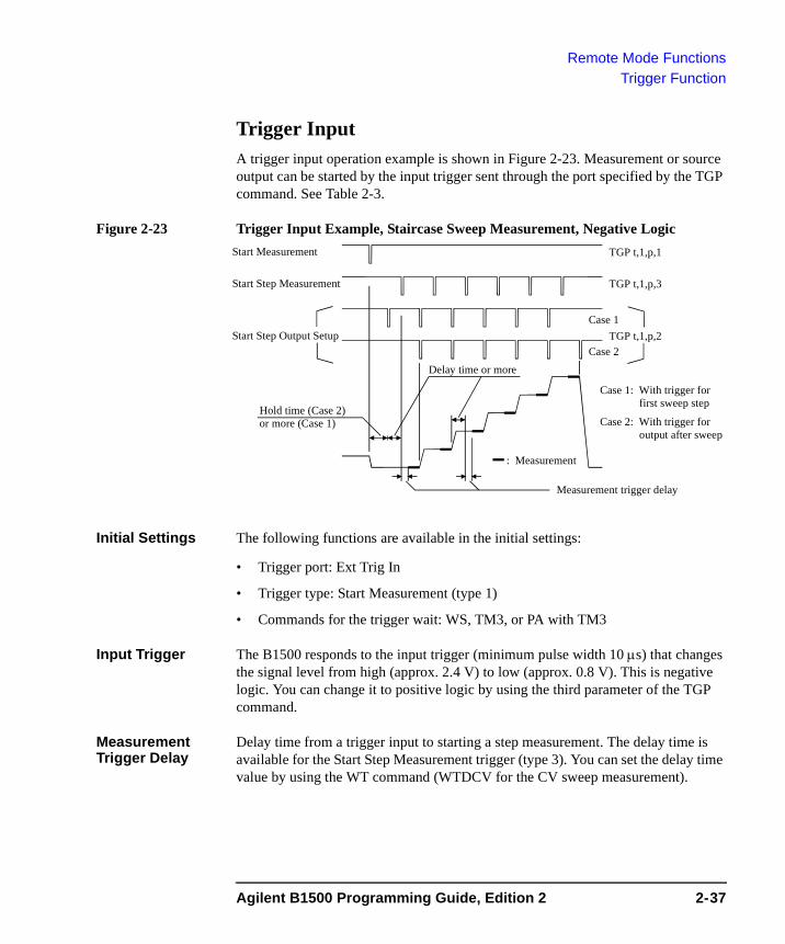
Remote Mode FunctionsTrigger Function
Trigger InputA trigger input operation example is shown in Figure 2-23. Measurement or source output can be started by the input trigger sent through the port specified by the TGP command. See Table 2-3.
Figure 2-23 Trigger Input Example, Staircase Sweep Measurement, Negative Logic
Initial Settings The following functions are available in the initial settings:
• Trigger port: Ext Trig In
• Trigger type: Start Measurement (type 1)
• Commands for the trigger wait: WS, TM3, or PA with TM3
Input Trigger The B1500 responds to the input trigger (minimum pulse width 10 μs) that changes the signal level from high (approx. 2.4 V) to low (approx. 0.8 V). This is negative logic. You can change it to positive logic by using the third parameter of the TGP command.
Measurement Trigger Delay
Delay time from a trigger input to starting a step measurement. The delay time is available for the Start Step Measurement trigger (type 3). You can set the delay time value by using the WT command (WTDCV for the CV sweep measurement).
: Measurement
TGP t,1,p,3
TGP t,1,p,2
TGP t,1,p,1
Hold time (Case 2)or more (Case 1)
Delay time or more
Start Step Measurement
Start Step Output Setup
Start Measurement
Measurement trigger delay
Case 1: With trigger for first sweep step
Case 2: With trigger for output after sweep
Case 1
Case 2
Agilent B1500 Programming Guide, Edition 2 2-37
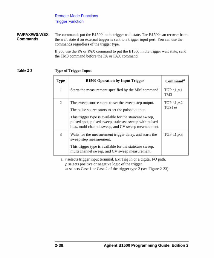
Remote Mode FunctionsTrigger Function
PA/PAX/WS/WSX Commands
The commands put the B1500 in the trigger wait state. The B1500 can recover from the wait state if an external trigger is sent to a trigger input port. You can use the commands regardless of the trigger type.
If you use the PA or PAX command to put the B1500 in the trigger wait state, send the TM3 command before the PA or PAX command.
Table 2-3 Type of Trigger Input
Type B1500 Operation by Input Trigger Commanda
a. t selects trigger input terminal, Ext Trig In or a digital I/O path. p selects positive or negative logic of the trigger.m selects Case 1 or Case 2 of the trigger type 2 (see Figure 2-23).
1 Starts the measurement specified by the MM command. TGP t,1,p,1 TM3
2 The sweep source starts to set the sweep step output.
The pulse source starts to set the pulsed output.
This trigger type is available for the staircase sweep, pulsed spot, pulsed sweep, staircase sweep with pulsed bias, multi channel sweep, and CV sweep measurement.
TGP t,1,p,2 TGSI m
3 Waits for the measurement trigger delay, and starts the sweep step measurement.
This trigger type is available for the staircase sweep, multi channel sweep, and CV sweep measurement.
TGP t,1,p,3
2-38 Agilent B1500 Programming Guide, Edition 2
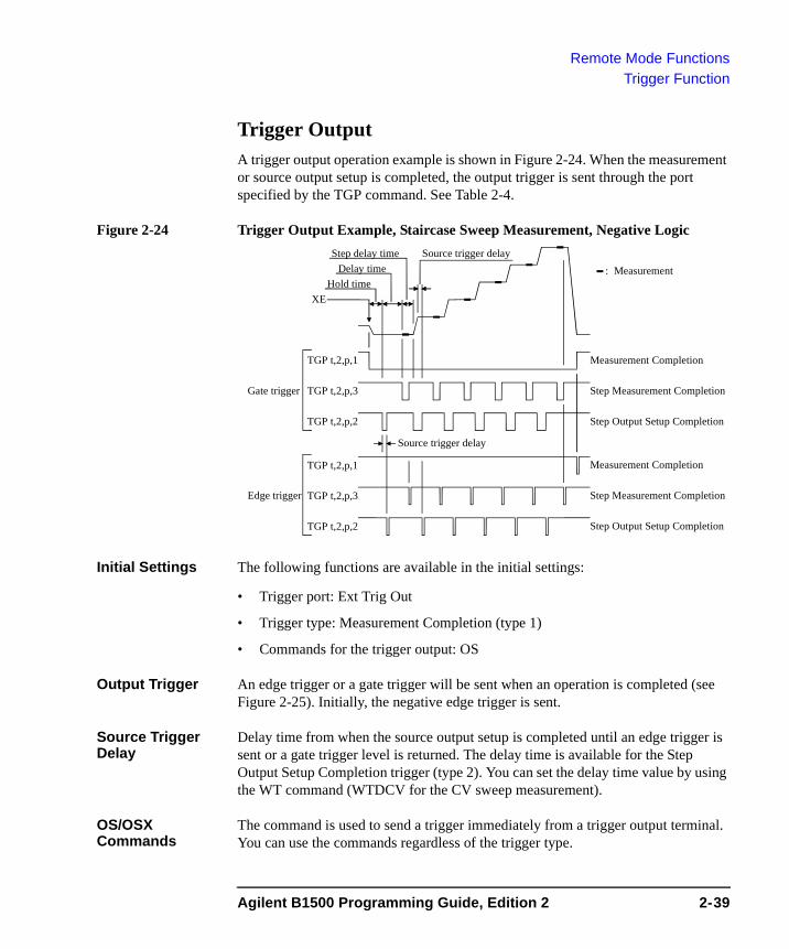
Remote Mode FunctionsTrigger Function
Trigger OutputA trigger output operation example is shown in Figure 2-24. When the measurement or source output setup is completed, the output trigger is sent through the port specified by the TGP command. See Table 2-4.
Figure 2-24 Trigger Output Example, Staircase Sweep Measurement, Negative Logic
Initial Settings The following functions are available in the initial settings:
• Trigger port: Ext Trig Out
• Trigger type: Measurement Completion (type 1)
• Commands for the trigger output: OS
Output Trigger An edge trigger or a gate trigger will be sent when an operation is completed (see Figure 2-25). Initially, the negative edge trigger is sent.
Source Trigger Delay
Delay time from when the source output setup is completed until an edge trigger is sent or a gate trigger level is returned. The delay time is available for the Step Output Setup Completion trigger (type 2). You can set the delay time value by using the WT command (WTDCV for the CV sweep measurement).
OS/OSX Commands
The command is used to send a trigger immediately from a trigger output terminal. You can use the commands regardless of the trigger type.
: Measurement
TGP t,2,p,3
XE
TGP t,2,p,2
TGP t,2,p,1
TGP t,2,p,3
TGP t,2,p,2
TGP t,2,p,1
Gate trigger
Edge trigger
Source trigger delay
Hold timeDelay time
Source trigger delay
Step delay time
Step Measurement Completion
Step Output Setup Completion
Measurement Completion
Step Measurement Completion
Step Output Setup Completion
Measurement Completion
Agilent B1500 Programming Guide, Edition 2 2-39
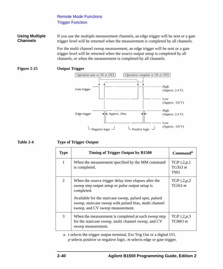
Remote Mode FunctionsTrigger Function
Using Multiple Channels
If you use the multiple measurement channels, an edge trigger will be sent or a gate trigger level will be returned when the measurement is completed by all channels.
For the multi channel sweep measurement, an edge trigger will be sent or a gate trigger level will be returned when the source output setup is completed by all channels, or when the measurement is completed by all channels.
Figure 2-25 Output Trigger
Table 2-4 Type of Trigger Output
Type Timing of Trigger Output by B1500 Commanda
a. t selects the trigger output terminal, Ext Trig Out or a digital I/O. p selects positive or negative logic. m selects edge or gate trigger.
1 When the measurement specified by the MM command is completed.
TGP t,2,p,1 TGXO m TM3
2 When the source trigger delay time elapses after the sweep step output setup or pulse output setup is completed.
Available for the staircase sweep, pulsed spot, pulsed sweep, staircase sweep with pulsed bias, multi channel sweep, and CV sweep measurement.
TGP t,2,p,2 TGSO m
3 When the measurement is completed at each sweep step for the staircase sweep, multi channel sweep, and CV sweep measurement.
TGP t,2,p,3 TGMO m
Edge trigger
Gate trigger
Negative logic Positive logic
High(Approx. 2.4 V)
Low(Approx. 0.8 V)
Operation complete or OS or OSXOperation start or OS or OSX
Approx. 10us
High(Approx. 2.4 V)
Low(Approx. 0.8 V)
2-40 Agilent B1500 Programming Guide, Edition 2
Remote Mode FunctionsTrigger Function
Using Trigger Function• “To Make Wait State Using PA/PAX”
• “To Make Wait State Using WS/WSX”
• “To Send Trigger Using OS/OSX”
• “To Receive Measurement Trigger”
• “To Specify Trigger Port and Receive Trigger”
• “To Control Measurement Timing Using External Trigger”
To Make Wait State Using PA/PAXThe PA or PAX command puts the B1500 into a wait state. The B1500 can be recovered from the wait state when the specified wait time elapses, or when an event selected by the TM command occurs. Then the B1500 executes the commands following the PA/PAX command. The event only releases the wait state set by the PA/PAX command.
The wait time parameter is available for the PA/PAX command. If you specify the wait time, the wait state continues until the time elapses or until the event occurs.
Available value: -99.9999 to 99.9999 s, in 100 μs resolution.
If you set a negative value, the wait state is kept until the event occurs.
You can select the event by using the TM command. If you want to use an external trigger as the event, enter the TM3 command. Then the PA/PAX command waits for the XE command execution, or:
• PA waits for a trigger sent to the Ext Trig In terminal.
• PAX waits for a trigger sent to the specified terminal.
In the initial setting, negative logic is available. To change it to positive, send the TGP command.
NOTE The TM command is used to select the event effective for starting measurement, or releasing the wait time set by the PA or PAX command. Enter the TM command before the PA or PAX command.
Agilent B1500 Programming Guide, Edition 2 2-41
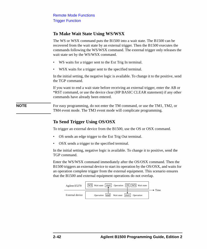
Remote Mode FunctionsTrigger Function
To Make Wait State Using WS/WSXThe WS or WSX command puts the B1500 into a wait state. The B1500 can be recovered from the wait state by an external trigger. Then the B1500 executes the commands following the WS/WSX command. The external trigger only releases the wait state set by the WS/WSX command.
• WS waits for a trigger sent to the Ext Trig In terminal.
• WSX waits for a trigger sent to the specified terminal.
In the initial setting, the negative logic is available. To change it to the positive, send the TGP command.
If you want to end a wait state before receiving an external trigger, enter the AB or *RST command, or use the device clear (HP BASIC CLEAR statement) if any other commands have already been entered.
NOTE For easy programming, do not enter the TM command, or use the TM1, TM2, or TM4 event mode. The TM3 event mode will complicate programming.
To Send Trigger Using OS/OSXTo trigger an external device from the B1500, use the OS or OSX command.
• OS sends an edge trigger to the Ext Trig Out terminal.
• OSX sends a trigger to the specified terminal.
In the initial setting, negative logic is available. To change it to positive, send the TGP command.
Enter the WS/WSX command immediately after the OS/OSX command. Then the B1500 triggers an external device to start its operation by the OS/OSX, and waits for an operation complete trigger from the external equipment. This scenario ensures that the B1500 and external equipment operations do not overlap.
Agilent E5270 WS Wait state
External device
Time
Operation end
Operation OSstart
Wait state start Operation
Wait stateWS
2-42 Agilent B1500 Programming Guide, Edition 2
Remote Mode FunctionsTrigger Function
To Receive Measurement TriggerTo use an external trigger just for starting measurement, instead of the XE command, perform the next step. This is not effective for the high speed spot measurement.
1. Connect a BNC cable between the Ext Trig In connector and a trigger output connector of an external device.
2. Create a control program. Then the TM3 command and HP BASIC ENTER statement should be entered as shown in the following example:
:OUTPUT @B1500;”MM1” ! Sets spot measurement mode
: ! Sets measurement condition:
OUTPUT @B1500;”TM3” ! Uses external triggerENTER @B1500 USING ”#,3X,12D,2X”;M_data
:
3. Execute the control program.
The B1500 sets the measurement conditions, and waits for an external trigger (negative trigger) sent to the Ext Trig In connector.
When the trigger is received, the B1500 starts measurement. When measurement is completed, the B1500 sends a negative edge trigger to the Ext Trig Out connector, and puts the measurement data in the data output buffer.
NOTE The HP BASIC ENTER statement pauses program execution until measurement data is put in the data buffer, reads the data from the buffer, and then continues program execution.
Start measurement
Measurement completion
Ext Trig In
Ext Trig Out
Agilent B1500 Programming Guide, Edition 2 2-43
Remote Mode FunctionsTrigger Function
To Specify Trigger Port and Receive TriggerTo use an external trigger just for starting measurement, instead of the XE command, perform the next step. This is not effective for the high speed spot measurement.
This example specifies the trigger input/output ports and uses the gate trigger for the output trigger.
1. Connect a BNC cable between the Ext Trig In connector and a trigger output connector of an external device.
2. Create a control program. Then the TM3 and TGP commands and HP BASIC ENTER statement should be entered as shown in the following example:
:OUTPUT @B1500;”MM1” ! Sets spot measurement mode
: ! Sets measurement condition:
OUTPUT @B1500;”TM3” ! Uses external triggerOUTPUT @B1500;”TGP -1,1,1,1” ! Sets trigger inputOUTPUT @B1500;”TGP -2,2,1,1” ! Sets trigger outputOUTPUT @B1500;”TGXO 2” ! Enables gate triggerENTER @B1500 USING ”#,3X,12D,2X”;M_data
:
3. Execute the control program.
The B1500 sets the measurement conditions, and waits for an external trigger (positive trigger) sent to the Ext Trig In connector.
When the trigger is received, the B1500 starts measurement and sends a positive gate trigger to the Ext Trig Out connector. When measurement is completed, the B1500 returns the gate trigger level to logical low, and puts the measurement data in the data output buffer.
NOTE The HP BASIC ENTER statement pauses program execution until measurement data is put in the data buffer, reads the data from the buffer, and then continues program execution.
Start measurement
Measurement completion
Ext Trig In
Ext Trig Out
2-44 Agilent B1500 Programming Guide, Edition 2
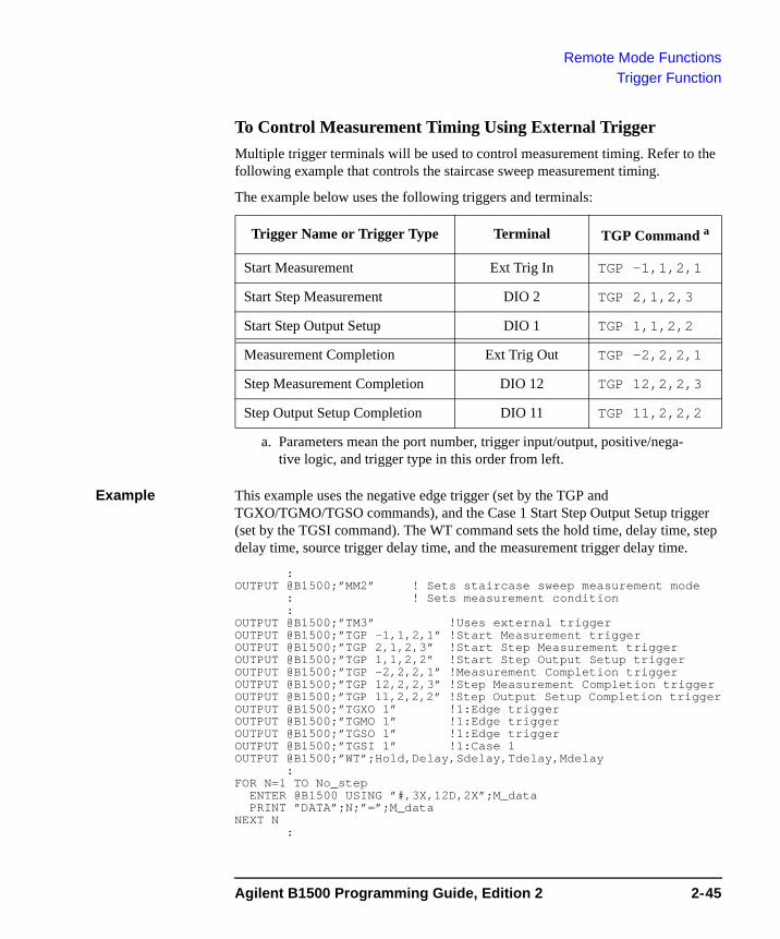
Remote Mode FunctionsTrigger Function
To Control Measurement Timing Using External TriggerMultiple trigger terminals will be used to control measurement timing. Refer to the following example that controls the staircase sweep measurement timing.
The example below uses the following triggers and terminals:
Example This example uses the negative edge trigger (set by the TGP and TGXO/TGMO/TGSO commands), and the Case 1 Start Step Output Setup trigger (set by the TGSI command). The WT command sets the hold time, delay time, step delay time, source trigger delay time, and the measurement trigger delay time.
:OUTPUT @B1500;”MM2” ! Sets staircase sweep measurement mode
: ! Sets measurement condition:
OUTPUT @B1500;”TM3” !Uses external triggerOUTPUT @B1500;”TGP -1,1,2,1” !Start Measurement triggerOUTPUT @B1500;”TGP 2,1,2,3” !Start Step Measurement triggerOUTPUT @B1500;”TGP 1,1,2,2” !Start Step Output Setup triggerOUTPUT @B1500;”TGP -2,2,2,1” !Measurement Completion triggerOUTPUT @B1500;”TGP 12,2,2,3” !Step Measurement Completion triggerOUTPUT @B1500;”TGP 11,2,2,2” !Step Output Setup Completion triggerOUTPUT @B1500;”TGXO 1” !1:Edge triggerOUTPUT @B1500;”TGMO 1” !1:Edge triggerOUTPUT @B1500;”TGSO 1” !1:Edge triggerOUTPUT @B1500;”TGSI 1” !1:Case 1OUTPUT @B1500;”WT”;Hold,Delay,Sdelay,Tdelay,Mdelay
:FOR N=1 TO No_step
ENTER @B1500 USING ”#,3X,12D,2X”;M_dataPRINT ”DATA”;N;”=”;M_data
NEXT N:
Trigger Name or Trigger Type Terminal TGP Command a
a. Parameters mean the port number, trigger input/output, positive/nega-tive logic, and trigger type in this order from left.
Start Measurement Ext Trig In TGP -1,1,2,1
Start Step Measurement DIO 2 TGP 2,1,2,3
Start Step Output Setup DIO 1 TGP 1,1,2,2
Measurement Completion Ext Trig Out TGP -2,2,2,1
Step Measurement Completion DIO 12 TGP 12,2,2,3
Step Output Setup Completion DIO 11 TGP 11,2,2,2
Agilent B1500 Programming Guide, Edition 2 2-45
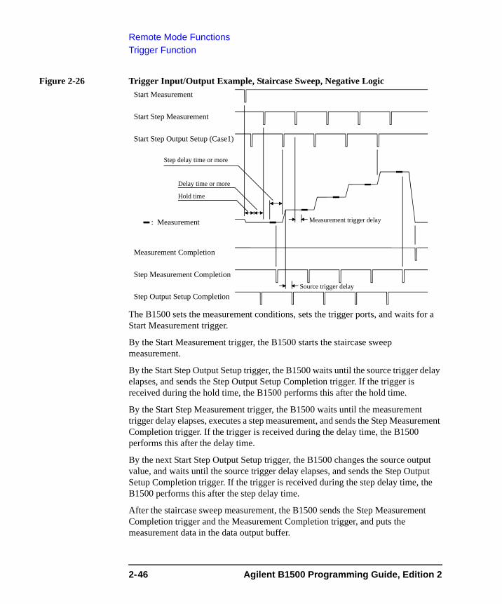
Remote Mode FunctionsTrigger Function
Figure 2-26 Trigger Input/Output Example, Staircase Sweep, Negative Logic
The B1500 sets the measurement conditions, sets the trigger ports, and waits for a Start Measurement trigger.
By the Start Measurement trigger, the B1500 starts the staircase sweep measurement.
By the Start Step Output Setup trigger, the B1500 waits until the source trigger delay elapses, and sends the Step Output Setup Completion trigger. If the trigger is received during the hold time, the B1500 performs this after the hold time.
By the Start Step Measurement trigger, the B1500 waits until the measurement trigger delay elapses, executes a step measurement, and sends the Step Measurement Completion trigger. If the trigger is received during the delay time, the B1500 performs this after the delay time.
By the next Start Step Output Setup trigger, the B1500 changes the source output value, and waits until the source trigger delay elapses, and sends the Step Output Setup Completion trigger. If the trigger is received during the step delay time, the B1500 performs this after the step delay time.
After the staircase sweep measurement, the B1500 sends the Step Measurement Completion trigger and the Measurement Completion trigger, and puts the measurement data in the data output buffer.
: Measurement
Start Step Measurement
Start Step Output Setup (Case1)
Start Measurement
Step Measurement Completion
Step Output Setup Completion
Measurement Completion
Hold time
Delay time or more
Step delay time or more
Source trigger delay
Measurement trigger delay
2-46 Agilent B1500 Programming Guide, Edition 2
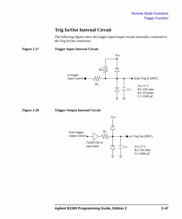
Remote Mode FunctionsTrigger Function
Trig In/Out Internal CircuitThe following figures show the trigger input/output circuits internally connected to the Trig In/Out connectors.
Figure 2-27 Trigger Input Internal Circuit
Figure 2-28 Trigger Output Internal Circuit
Vcc
R1
R2
to triggerinput control from Trig In (BNC)
Vcc=5 VR1=220 ohmR2=10 kohmC1=1000 pF
C1
Vcc
R1from triggeroutput control to Trig Out (BNC)
Vcc=5 VR1=150 ohmC1=1000 pF
74ABT245 orequivalent C1
Agilent B1500 Programming Guide, Edition 2 2-47
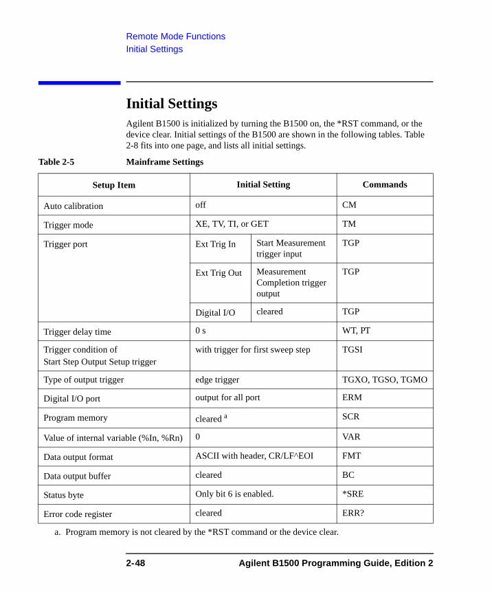
Remote Mode FunctionsInitial Settings
Initial Settings Agilent B1500 is initialized by turning the B1500 on, the *RST command, or the device clear. Initial settings of the B1500 are shown in the following tables. Table 2-8 fits into one page, and lists all initial settings.
Table 2-5 Mainframe Settings
Setup Item Initial Setting Commands
Auto calibration off CM
Trigger mode XE, TV, TI, or GET TM
Trigger port Ext Trig In Start Measurement trigger input
TGP
Ext Trig Out Measurement Completion trigger output
TGP
Digital I/O cleared TGP
Trigger delay time 0 s WT, PT
Trigger condition ofStart Step Output Setup trigger
with trigger for first sweep step TGSI
Type of output trigger edge trigger TGXO, TGSO, TGMO
Digital I/O port output for all port ERM
Program memory cleared a
a. Program memory is not cleared by the *RST command or the device clear.
SCR
Value of internal variable (%In, %Rn) 0 VAR
Data output format ASCII with header, CR/LF^EOI FMT
Data output buffer cleared BC
Status byte Only bit 6 is enabled. *SRE
Error code register cleared ERR?
2-48 Agilent B1500 Programming Guide, Edition 2
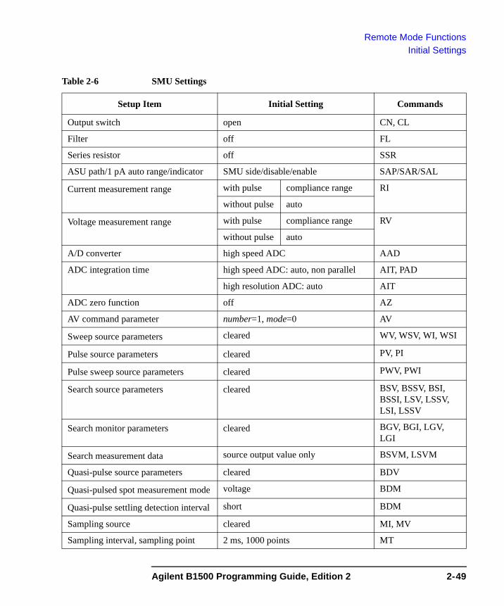
Remote Mode FunctionsInitial Settings
Table 2-6 SMU Settings
Setup Item Initial Setting Commands
Output switch open CN, CL
Filter off FL
Series resistor off SSR
ASU path/1 pA auto range/indicator SMU side/disable/enable SAP/SAR/SAL
Current measurement range with pulse compliance range RI
without pulse auto
Voltage measurement range with pulse compliance range RV
without pulse auto
A/D converter high speed ADC AAD
ADC integration time high speed ADC: auto, non parallel AIT, PAD
high resolution ADC: auto AIT
ADC zero function off AZ
AV command parameter number=1, mode=0 AV
Sweep source parameters cleared WV, WSV, WI, WSI
Pulse source parameters cleared PV, PI
Pulse sweep source parameters cleared PWV, PWI
Search source parameters cleared BSV, BSSV, BSI, BSSI, LSV, LSSV, LSI, LSSV
Search monitor parameters cleared BGV, BGI, LGV, LGI
Search measurement data source output value only BSVM, LSVM
Quasi-pulse source parameters cleared BDV
Quasi-pulsed spot measurement mode voltage BDM
Quasi-pulse settling detection interval short BDM
Sampling source cleared MI, MV
Sampling interval, sampling point 2 ms, 1000 points MT
Agilent B1500 Programming Guide, Edition 2 2-49
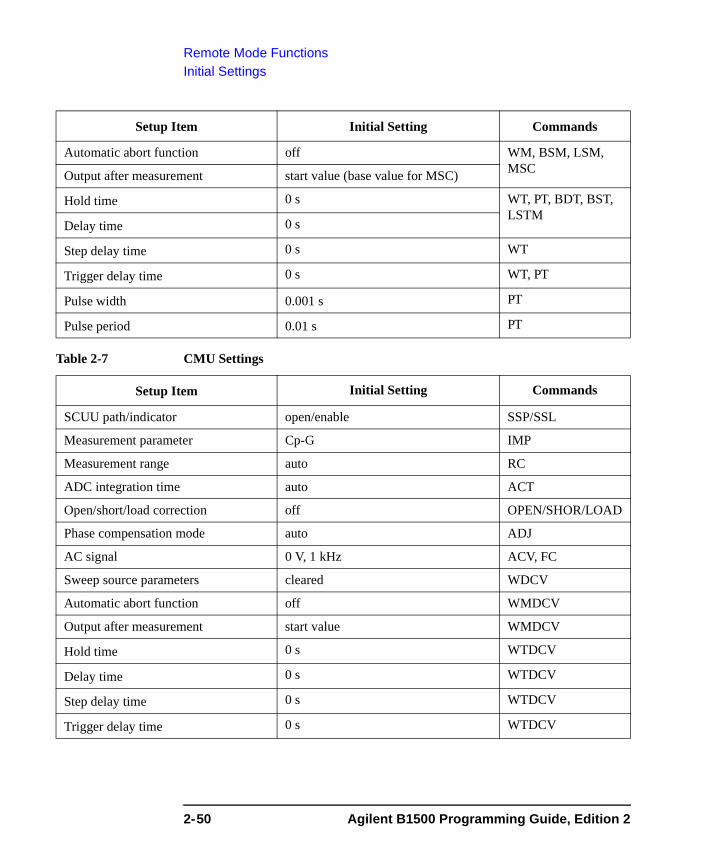
Remote Mode FunctionsInitial Settings
Table 2-7 CMU Settings
Automatic abort function off WM, BSM, LSM, MSCOutput after measurement start value (base value for MSC)
Hold time 0 s WT, PT, BDT, BST, LSTM
Delay time 0 s
Step delay time 0 s WT
Trigger delay time 0 s WT, PT
Pulse width 0.001 s PT
Pulse period 0.01 s PT
Setup Item Initial Setting Commands
SCUU path/indicator open/enable SSP/SSL
Measurement parameter Cp-G IMP
Measurement range auto RC
ADC integration time auto ACT
Open/short/load correction off OPEN/SHOR/LOAD
Phase compensation mode auto ADJ
AC signal 0 V, 1 kHz ACV, FC
Sweep source parameters cleared WDCV
Automatic abort function off WMDCV
Output after measurement start value WMDCV
Hold time 0 s WTDCV
Delay time 0 s WTDCV
Step delay time 0 s WTDCV
Trigger delay time 0 s WTDCV
Setup Item Initial Setting Commands
2-50 Agilent B1500 Programming Guide, Edition 2
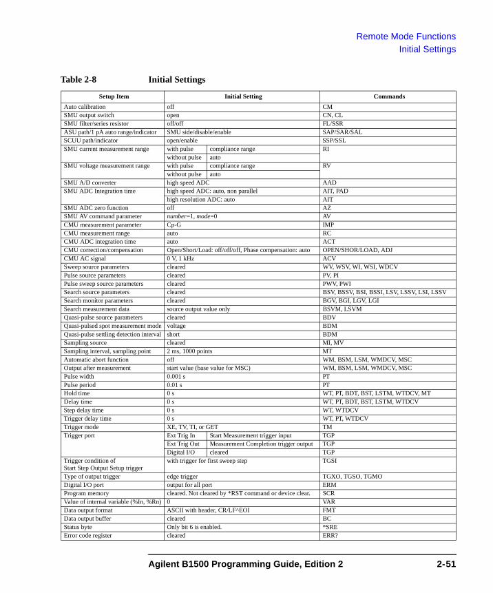
Remote Mode FunctionsInitial Settings
Table 2-8 Initial Settings
Setup Item Initial Setting CommandsAuto calibration off CMSMU output switch open CN, CLSMU filter/series resistor off/off FL/SSRASU path/1 pA auto range/indicator SMU side/disable/enable SAP/SAR/SALSCUU path/indicator open/enable SSP/SSLSMU current measurement range with pulse compliance range RI
without pulse autoSMU voltage measurement range with pulse compliance range RV
without pulse autoSMU A/D converter high speed ADC AADSMU ADC Integration time high speed ADC: auto, non parallel AIT, PAD
high resolution ADC: auto AITSMU ADC zero function off AZSMU AV command parameter number=1, mode=0 AVCMU measurement parameter Cp-G IMPCMU measurement range auto RCCMU ADC integration time auto ACTCMU correction/compensation Open/Short/Load: off/off/off, Phase compensation: auto OPEN/SHOR/LOAD, ADJCMU AC signal 0 V, 1 kHz ACVSweep source parameters cleared WV, WSV, WI, WSI, WDCVPulse source parameters cleared PV, PIPulse sweep source parameters cleared PWV, PWISearch source parameters cleared BSV, BSSV, BSI, BSSI, LSV, LSSV, LSI, LSSVSearch monitor parameters cleared BGV, BGI, LGV, LGISearch measurement data source output value only BSVM, LSVMQuasi-pulse source parameters cleared BDVQuasi-pulsed spot measurement mode voltage BDMQuasi-pulse settling detection interval short BDMSampling source cleared MI, MVSampling interval, sampling point 2 ms, 1000 points MTAutomatic abort function off WM, BSM, LSM, WMDCV, MSCOutput after measurement start value (base value for MSC) WM, BSM, LSM, WMDCV, MSCPulse width 0.001 s PTPulse period 0.01 s PTHold time 0 s WT, PT, BDT, BST, LSTM, WTDCV, MTDelay time 0 s WT, PT, BDT, BST, LSTM, WTDCVStep delay time 0 s WT, WTDCVTrigger delay time 0 s WT, PT, WTDCVTrigger mode XE, TV, TI, or GET TMTrigger port Ext Trig In Start Measurement trigger input TGP
Ext Trig Out Measurement Completion trigger output TGPDigital I/O cleared TGP
Trigger condition ofStart Step Output Setup trigger
with trigger for first sweep step TGSI
Type of output trigger edge trigger TGXO, TGSO, TGMODigital I/O port output for all port ERMProgram memory cleared. Not cleared by *RST command or device clear. SCRValue of internal variable (%In, %Rn) 0 VARData output format ASCII with header, CR/LF^EOI FMTData output buffer cleared BCStatus byte Only bit 6 is enabled. *SREError code register cleared ERR?
Agilent B1500 Programming Guide, Edition 2 2-51

Remote Mode FunctionsInitial Settings
2-52 Agilent B1500 Programming Guide, Edition 2
3 Programming Examples
Programming Examples
This chapter lists the Agilent FLEX commands (GPIB commands for the Agilent B1500) and explains the programming example for each measurement mode. This chapter contains the following sections.
• “Programming Basics for Visual Basic .NET Users”
• “High-Speed Spot Measurements”
• “Spot Measurements”
• “Pulsed Spot Measurements”
• “Staircase Sweep Measurements”
• “Pulsed Sweep Measurements”
• “Staircase Sweep with Pulsed Bias Measurements”
• “Quasi Pulsed Spot Measurements”
• “Linear Search Measurements”
• “Binary Search Measurements”
• “Multi Channel Sweep Measurements”
• “Sampling Measurements”
• “High-Speed Spot C Measurement”
• “Spot C Measurements”
• “CV Sweep Measurements”
• “Using Program Memory”
• “Using Trigger Function”
• “Reading Time Stamp Data”
• “Reading Binary Output Data”
• “Using Programs for 4142B”
• “Using Programs for 4155B/4156B/4155C/4156C”
3-2 Agilent B1500 Programming Guide, Edition 2

Programming Examples
Refer to Chapter 4, “Command Reference,” for the command syntax and descriptions of the Agilent B1500 FLEX commands.
The following command conventions are used in this chapter.
command Required command for measurement execution.
[command] Optional command for measurement execution.
parameter Required command parameter. A value or variable must be specified.
[parameter] Optional command parameter. A value may be specified.
NOTE About Example Program Code
Example programs described in this section have been written in the Microsoft Visual Basic .NET or the HP BASIC language. Most of the examples written in the Visual Basic .NET are provided as a subprogram that can be run with the project template shown in Table 3-1. To run the program, insert the example subprogram or your subprogram instead of the perform_meas subprogram in the template.
NOTE To Start Program
If you create the measurement program by using the example code shown in Table 3-1, the program can be run by clicking the Run button on the Visual Basic main window. Then a message box will appear. After that, click OK to continue.
NOTE After the Automatic Measurement
After the automatic measurements, open the measurement terminals or disconnect the device under test from the measurement terminals. If you leave the connection with the device, the device may be damaged by unexpected operations.
Do not leave the connection over 30 minutes after measurement if the auto calibration is set to ON. Then, the Agilent B1500 performs the self-calibration automatically every 30 minutes after measurement. The calibration requires to open the measurement terminals.
To disable the auto calibration, enter the CM 0 command.
Agilent B1500 Programming Guide, Edition 2 3-3
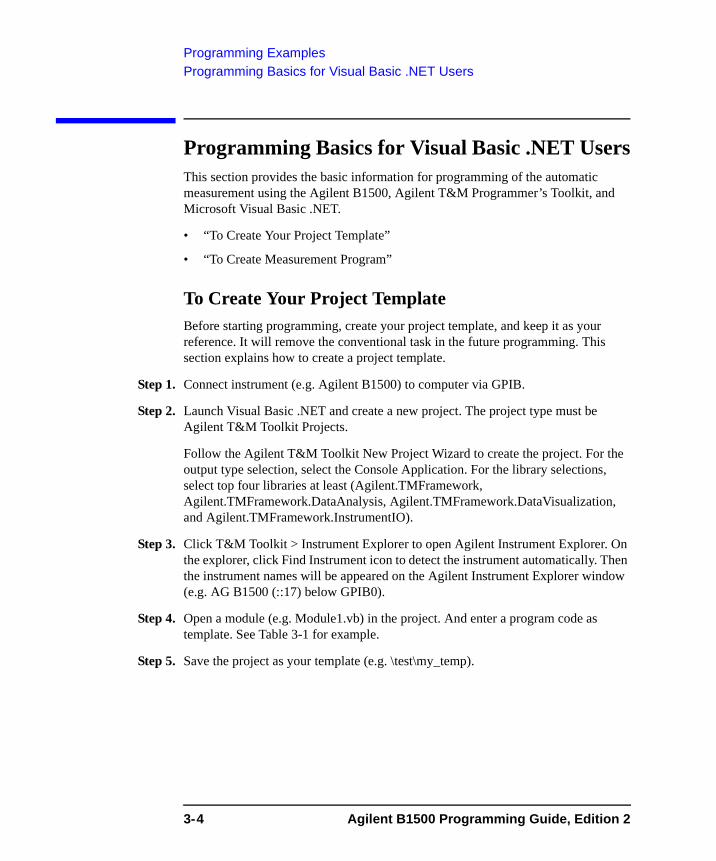
Programming ExamplesProgramming Basics for Visual Basic .NET Users
Programming Basics for Visual Basic .NET UsersThis section provides the basic information for programming of the automatic measurement using the Agilent B1500, Agilent T&M Programmer’s Toolkit, and Microsoft Visual Basic .NET.
• “To Create Your Project Template”
• “To Create Measurement Program”
To Create Your Project TemplateBefore starting programming, create your project template, and keep it as your reference. It will remove the conventional task in the future programming. This section explains how to create a project template.
Step 1. Connect instrument (e.g. Agilent B1500) to computer via GPIB.
Step 2. Launch Visual Basic .NET and create a new project. The project type must be Agilent T&M Toolkit Projects.
Follow the Agilent T&M Toolkit New Project Wizard to create the project. For the output type selection, select the Console Application. For the library selections, select top four libraries at least (Agilent.TMFramework, Agilent.TMFramework.DataAnalysis, Agilent.TMFramework.DataVisualization, and Agilent.TMFramework.InstrumentIO).
Step 3. Click T&M Toolkit > Instrument Explorer to open Agilent Instrument Explorer. On the explorer, click Find Instrument icon to detect the instrument automatically. Then the instrument names will be appeared on the Agilent Instrument Explorer window (e.g. AG B1500 (::17) below GPIB0).
Step 4. Open a module (e.g. Module1.vb) in the project. And enter a program code as template. See Table 3-1 for example.
Step 5. Save the project as your template (e.g. \test\my_temp).
3-4 Agilent B1500 Programming Guide, Edition 2
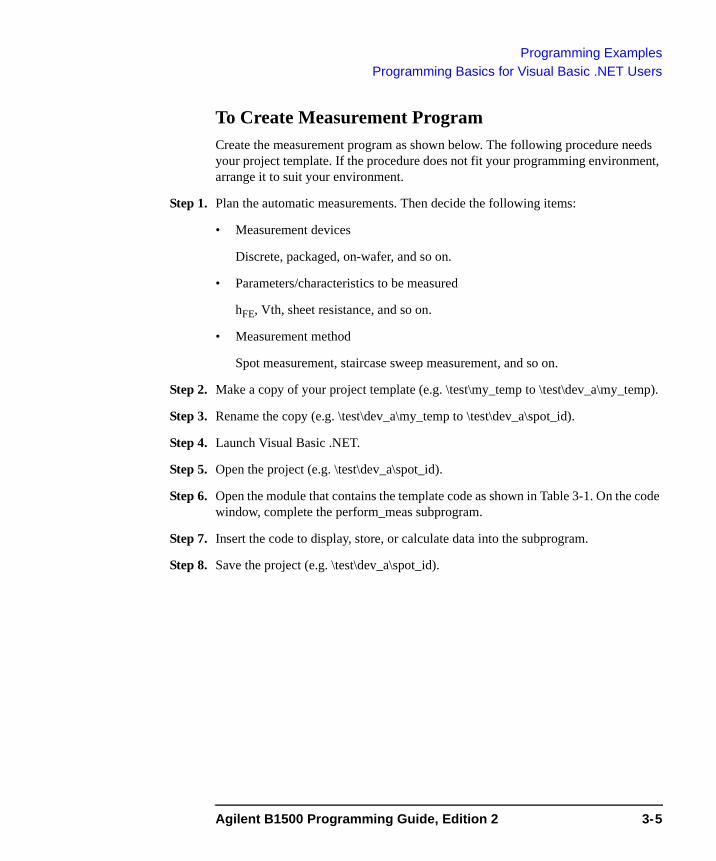
Programming ExamplesProgramming Basics for Visual Basic .NET Users
To Create Measurement ProgramCreate the measurement program as shown below. The following procedure needs your project template. If the procedure does not fit your programming environment, arrange it to suit your environment.
Step 1. Plan the automatic measurements. Then decide the following items:
• Measurement devices
Discrete, packaged, on-wafer, and so on.
• Parameters/characteristics to be measured
hFE, Vth, sheet resistance, and so on.
• Measurement method
Spot measurement, staircase sweep measurement, and so on.
Step 2. Make a copy of your project template (e.g. \test\my_temp to \test\dev_a\my_temp).
Step 3. Rename the copy (e.g. \test\dev_a\my_temp to \test\dev_a\spot_id).
Step 4. Launch Visual Basic .NET.
Step 5. Open the project (e.g. \test\dev_a\spot_id).
Step 6. Open the module that contains the template code as shown in Table 3-1. On the code window, complete the perform_meas subprogram.
Step 7. Insert the code to display, store, or calculate data into the subprogram.
Step 8. Save the project (e.g. \test\dev_a\spot_id).
Agilent B1500 Programming Guide, Edition 2 3-5
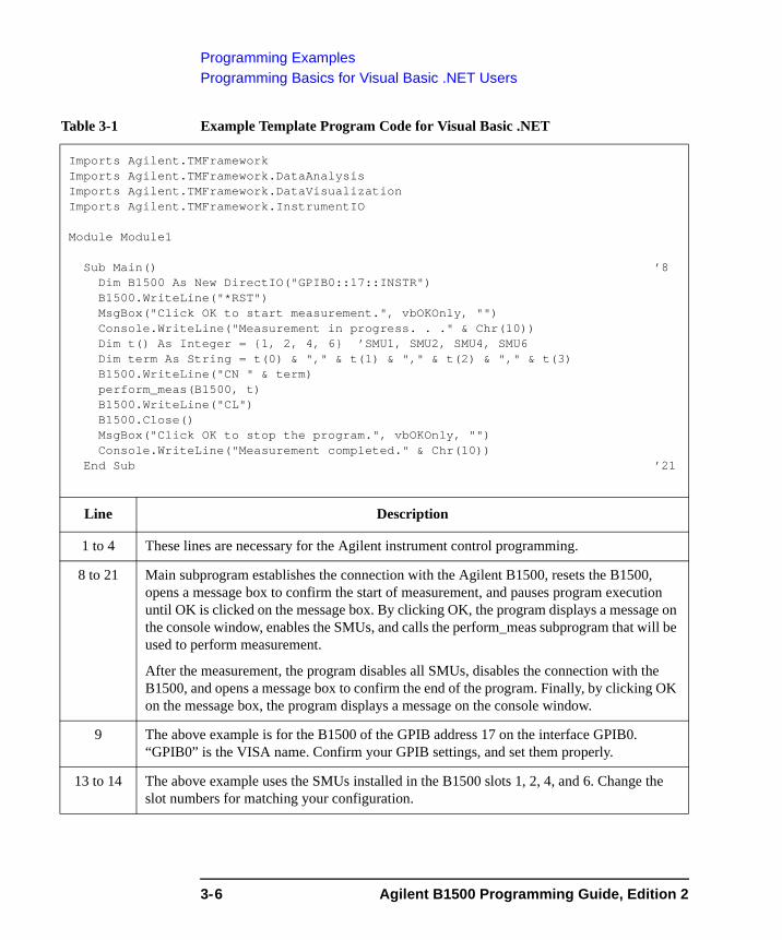
Programming ExamplesProgramming Basics for Visual Basic .NET Users
Table 3-1 Example Template Program Code for Visual Basic .NET
Imports Agilent.TMFrameworkImports Agilent.TMFramework.DataAnalysisImports Agilent.TMFramework.DataVisualizationImports Agilent.TMFramework.InstrumentIO
Module Module1
Sub Main() ’8Dim B1500 As New DirectIO("GPIB0::17::INSTR")B1500.WriteLine("*RST")MsgBox("Click OK to start measurement.", vbOKOnly, "")Console.WriteLine("Measurement in progress. . ." & Chr(10))Dim t() As Integer = {1, 2, 4, 6} ’SMU1, SMU2, SMU4, SMU6Dim term As String = t(0) & "," & t(1) & "," & t(2) & "," & t(3)B1500.WriteLine("CN " & term)perform_meas(B1500, t)B1500.WriteLine("CL")B1500.Close()MsgBox("Click OK to stop the program.", vbOKOnly, "")Console.WriteLine("Measurement completed." & Chr(10))
End Sub ’21
Line Description
1 to 4 These lines are necessary for the Agilent instrument control programming.
8 to 21 Main subprogram establishes the connection with the Agilent B1500, resets the B1500, opens a message box to confirm the start of measurement, and pauses program execution until OK is clicked on the message box. By clicking OK, the program displays a message on the console window, enables the SMUs, and calls the perform_meas subprogram that will be used to perform measurement.
After the measurement, the program disables all SMUs, disables the connection with the B1500, and opens a message box to confirm the end of the program. Finally, by clicking OK on the message box, the program displays a message on the console window.
9 The above example is for the B1500 of the GPIB address 17 on the interface GPIB0. “GPIB0” is the VISA name. Confirm your GPIB settings, and set them properly.
13 to 14 The above example uses the SMUs installed in the B1500 slots 1, 2, 4, and 6. Change the slot numbers for matching your configuration.
3-6 Agilent B1500 Programming Guide, Edition 2
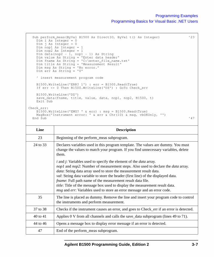
Programming ExamplesProgramming Basics for Visual Basic .NET Users
Sub perform_meas(ByVal B1500 As DirectIO, ByVal t() As Integer) ’23Dim i As Integer = 0Dim j As Integer = 0Dim nop1 As Integer = 1Dim nop2 As Integer = 1Dim data(nop2 - 1, nop1 - 1) As StringDim value As String = "Enter data header"Dim fname As String = "C:\enter_file_name.txt"Dim title As String = "Measurement Result"Dim msg As String = "No error."Dim err As String = "0"
’ insert measurement program code
B1500.WriteLine("ERR? 1") : err = B1500.Read(True)If err <> 0 Then B1500.WriteLine("DZ") : GoTo Check_err
B1500.WriteLine("DZ")save_data(fname, title, value, data, nop1, nop2, B1500, t)Exit Sub
Check_err:B1500.WriteLine("EMG? " & err) : msg = B1500.Read(True)MsgBox("Instrument error: " & err & Chr(10) & msg, vbOKOnly, "")
End Sub ’47
Line Description
23 Beginning of the perform_meas subprogram.
24 to 33 Declares variables used in this program template. The values are dummy. You must change the values to match your program. If you find unnecessary variables, delete them.
i and j: Variables used to specify the element of the data array.nop1 and nop2: Number of measurement steps. Also used to declare the data array.data: String data array used to store the measurement result data.val: String data variable to store the header (first line) of the displayed data.fname: Full path name of the measurement result data file.title: Title of the message box used to display the measurement result data.msg and err: Variables used to store an error message and an error code.
35 The line is placed as dummy. Remove the line and insert your program code to control the instruments and perform measurement.
37 to 38 Checks if the instrument causes an error, and goes to Check_err if an error is detected.
40 to 41 Applies 0 V from all channels and calls the save_data subprogram (lines 49 to 71).
44 to 46 Opens a message box to display error message if an error is detected.
47 End of the perform_meas subprogram.
Agilent B1500 Programming Guide, Edition 2 3-7
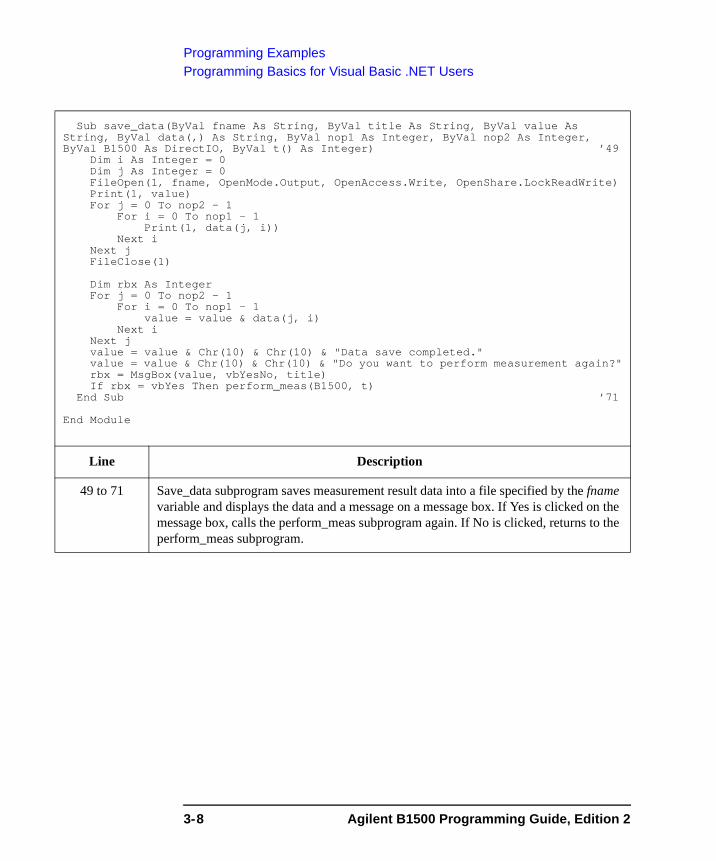
Programming ExamplesProgramming Basics for Visual Basic .NET Users
Sub save_data(ByVal fname As String, ByVal title As String, ByVal value As String, ByVal data(,) As String, ByVal nop1 As Integer, ByVal nop2 As Integer, ByVal B1500 As DirectIO, ByVal t() As Integer) ’49
Dim i As Integer = 0Dim j As Integer = 0FileOpen(1, fname, OpenMode.Output, OpenAccess.Write, OpenShare.LockReadWrite)Print(1, value)For j = 0 To nop2 - 1
For i = 0 To nop1 - 1Print(1, data(j, i))
Next iNext jFileClose(1)
Dim rbx As IntegerFor j = 0 To nop2 - 1
For i = 0 To nop1 - 1value = value & data(j, i)
Next iNext jvalue = value & Chr(10) & Chr(10) & "Data save completed."value = value & Chr(10) & Chr(10) & "Do you want to perform measurement again?"rbx = MsgBox(value, vbYesNo, title)If rbx = vbYes Then perform_meas(B1500, t)
End Sub ’71
End Module
Line Description
49 to 71 Save_data subprogram saves measurement result data into a file specified by the fname variable and displays the data and a message on a message box. If Yes is clicked on the message box, calls the perform_meas subprogram again. If No is clicked, returns to the perform_meas subprogram.
3-8 Agilent B1500 Programming Guide, Edition 2
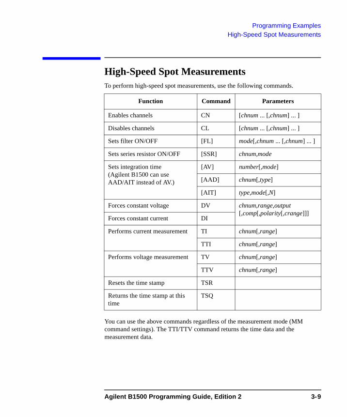
Programming ExamplesHigh-Speed Spot Measurements
High-Speed Spot MeasurementsTo perform high-speed spot measurements, use the following commands.
You can use the above commands regardless of the measurement mode (MM command settings). The TTI/TTV command returns the time data and the measurement data.
Function Command Parameters
Enables channels CN [chnum ... [,chnum] ... ]
Disables channels CL [chnum ... [,chnum] ... ]
Sets filter ON/OFF [FL] mode[,chnum ... [,chnum] ... ]
Sets series resistor ON/OFF [SSR] chnum,mode
Sets integration time (Agilent B1500 can use AAD/AIT instead of AV.)
[AV] number[,mode]
[AAD] chnum[,type]
[AIT] type,mode[,N]
Forces constant voltage DV chnum,range,output [,comp[,polarity[,crange]]]
Forces constant current DI
Performs current measurement TI chnum[,range]
TTI chnum[,range]
Performs voltage measurement TV chnum[,range]
TTV chnum[,range]
Resets the time stamp TSR
Returns the time stamp at this time
TSQ
Agilent B1500 Programming Guide, Edition 2 3-9
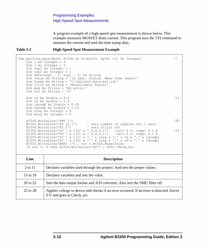
Programming ExamplesHigh-Speed Spot Measurements
A program example of a high-speed spot measurement is shown below. This example measures MOSFET drain current. This program uses the TTI command to measure the current and read the time stamp data.
Table 3-2 High-Speed Spot Measurement Example
Sub perform_meas(ByVal B1500 As DirectIO, ByVal t() As Integer) ’1Dim i As Integer = 0Dim j As Integer = 0Dim nop1 As Integer = 1Dim nop2 As Integer = 1Dim data(nop2 - 1, nop1 - 1) As StringDim value As String = "Id (mA), Status, Meas Time (msec)"Dim fname As String = "C:\Agilent\data\ex1.txt"Dim title As String = "Measurement Result"Dim msg As String = "No error."Dim err As String = "0"
Dim vd As Double = 0.5 ’13Dim vg As Double = 0.5Dim idcomp As Double = 0.05Dim igcomp As Double = 0.01Dim orng As Integer = 0Dim mrng As Integer = 0
B1500.WriteLine("FMT 1") ’20B1500.WriteLine("AV 10,1") ’ sets number of samples for 1 dataB1500.WriteLine("FL 0") ’ sets filter offB1500.WriteLine("DV " & t(3) & ",0,0,0.1") ’out= 0 V, comp= 0.1 A ’23B1500.WriteLine("DV " & t(2) & ",0,0,0.1") ’out= 0 V, comp= 0.1 AB1500.WriteLine("DV " & t(1) & "," & orng & "," & vg & "," & igcomp)B1500.WriteLine("DV " & t(0) & "," & orng & "," & vd & "," & idcomp)B1500.WriteLine("ERR? 1") : err = B1500.Read(True)If err <> 0 Then B1500.WriteLine("DZ") : GoTo Check_err
Line Description
2 to 11 Declares variables used through the project. And sets the proper values.
13 to 18 Declares variables and sets the value.
20 to 22 Sets the data output format and A/D converter. Also sets the SMU filter off.
23 to 28 Applies voltage to device and checks if an error occurred. If an error is detected, forces 0 V and goes to Check_err.
3-10 Agilent B1500 Programming Guide, Edition 2
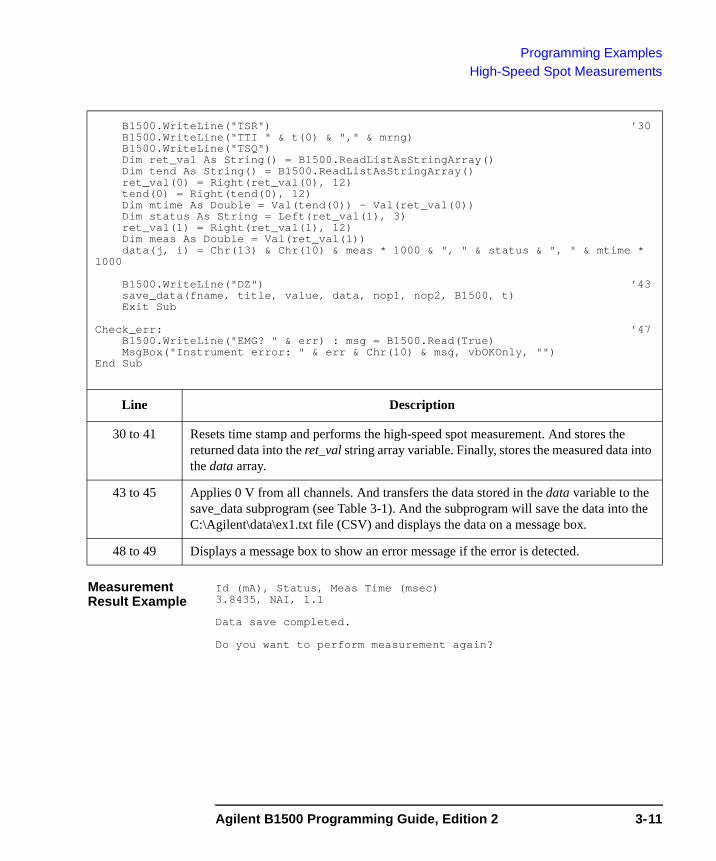
Programming ExamplesHigh-Speed Spot Measurements
Measurement Result Example
Id (mA), Status, Meas Time (msec)3.8435, NAI, 1.1
Data save completed.
Do you want to perform measurement again?
B1500.WriteLine("TSR") ’30B1500.WriteLine("TTI " & t(0) & "," & mrng)B1500.WriteLine("TSQ")Dim ret_val As String() = B1500.ReadListAsStringArray()Dim tend As String() = B1500.ReadListAsStringArray()ret_val(0) = Right(ret_val(0), 12)tend(0) = Right(tend(0), 12)Dim mtime As Double = Val(tend(0)) - Val(ret_val(0))Dim status As String = Left(ret_val(1), 3)ret_val(1) = Right(ret_val(1), 12)Dim meas As Double = Val(ret_val(1))data(j, i) = Chr(13) & Chr(10) & meas * 1000 & ", " & status & ", " & mtime *
1000
B1500.WriteLine("DZ") ’43save_data(fname, title, value, data, nop1, nop2, B1500, t)Exit Sub
Check_err: ’47B1500.WriteLine("EMG? " & err) : msg = B1500.Read(True)MsgBox("Instrument error: " & err & Chr(10) & msg, vbOKOnly, "")
End Sub
Line Description
30 to 41 Resets time stamp and performs the high-speed spot measurement. And stores the returned data into the ret_val string array variable. Finally, stores the measured data into the data array.
43 to 45 Applies 0 V from all channels. And transfers the data stored in the data variable to the save_data subprogram (see Table 3-1). And the subprogram will save the data into the C:\Agilent\data\ex1.txt file (CSV) and displays the data on a message box.
48 to 49 Displays a message box to show an error message if the error is detected.
Agilent B1500 Programming Guide, Edition 2 3-11
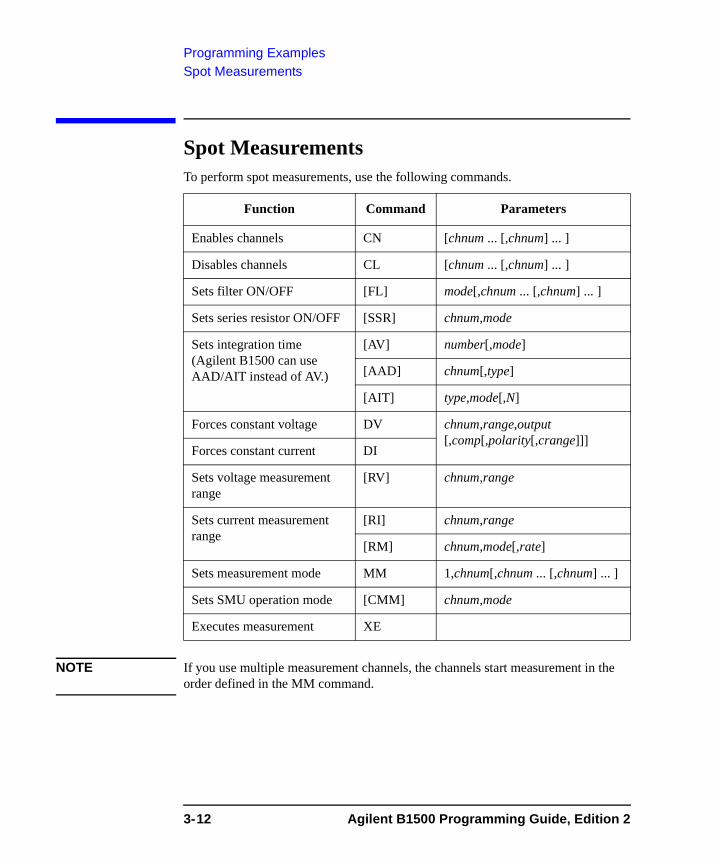
Programming ExamplesSpot Measurements
Spot Measurements To perform spot measurements, use the following commands.
NOTE If you use multiple measurement channels, the channels start measurement in the order defined in the MM command.
Function Command Parameters
Enables channels CN [chnum ... [,chnum] ... ]
Disables channels CL [chnum ... [,chnum] ... ]
Sets filter ON/OFF [FL] mode[,chnum ... [,chnum] ... ]
Sets series resistor ON/OFF [SSR] chnum,mode
Sets integration time (Agilent B1500 can use AAD/AIT instead of AV.)
[AV] number[,mode]
[AAD] chnum[,type]
[AIT] type,mode[,N]
Forces constant voltage DV chnum,range,output [,comp[,polarity[,crange]]]
Forces constant current DI
Sets voltage measurement range
[RV] chnum,range
Sets current measurement range
[RI] chnum,range
[RM] chnum,mode[,rate]
Sets measurement mode MM 1,chnum[,chnum ... [,chnum] ... ]
Sets SMU operation mode [CMM] chnum,mode
Executes measurement XE
3-12 Agilent B1500 Programming Guide, Edition 2
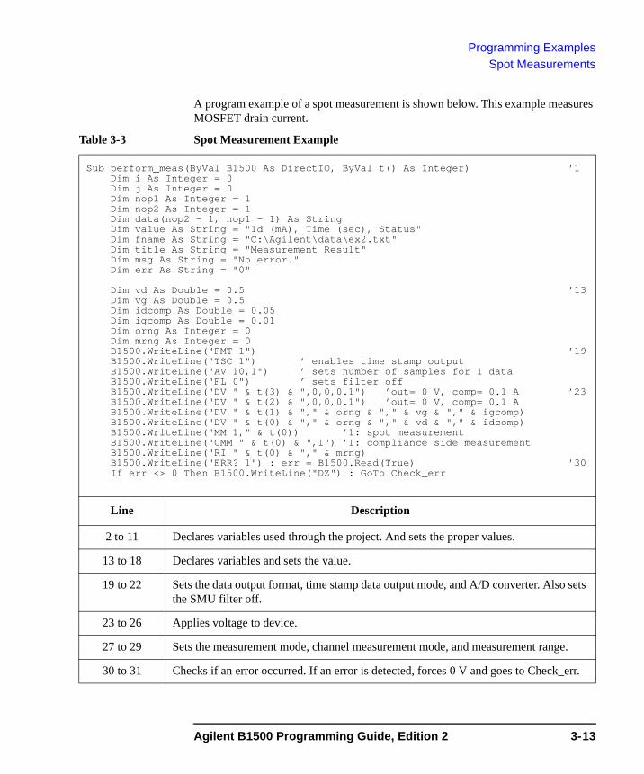
Programming ExamplesSpot Measurements
A program example of a spot measurement is shown below. This example measures MOSFET drain current.
Table 3-3 Spot Measurement Example
Sub perform_meas(ByVal B1500 As DirectIO, ByVal t() As Integer) ’1Dim i As Integer = 0Dim j As Integer = 0Dim nop1 As Integer = 1Dim nop2 As Integer = 1Dim data(nop2 - 1, nop1 - 1) As StringDim value As String = "Id (mA), Time (sec), Status"Dim fname As String = "C:\Agilent\data\ex2.txt"Dim title As String = "Measurement Result"Dim msg As String = "No error."Dim err As String = "0"
Dim vd As Double = 0.5 ’13Dim vg As Double = 0.5Dim idcomp As Double = 0.05Dim igcomp As Double = 0.01Dim orng As Integer = 0Dim mrng As Integer = 0B1500.WriteLine("FMT 1") ’19B1500.WriteLine("TSC 1") ’ enables time stamp outputB1500.WriteLine("AV 10,1") ’ sets number of samples for 1 dataB1500.WriteLine("FL 0") ’ sets filter offB1500.WriteLine("DV " & t(3) & ",0,0,0.1") ’out= 0 V, comp= 0.1 A ’23B1500.WriteLine("DV " & t(2) & ",0,0,0.1") ’out= 0 V, comp= 0.1 AB1500.WriteLine("DV " & t(1) & "," & orng & "," & vg & "," & igcomp)B1500.WriteLine("DV " & t(0) & "," & orng & "," & vd & "," & idcomp)B1500.WriteLine("MM 1," & t(0)) ’1: spot measurementB1500.WriteLine("CMM " & t(0) & ",1") ’1: compliance side measurementB1500.WriteLine("RI " & t(0) & "," & mrng)B1500.WriteLine("ERR? 1") : err = B1500.Read(True) ’30If err <> 0 Then B1500.WriteLine("DZ") : GoTo Check_err
Line Description
2 to 11 Declares variables used through the project. And sets the proper values.
13 to 18 Declares variables and sets the value.
19 to 22 Sets the data output format, time stamp data output mode, and A/D converter. Also sets the SMU filter off.
23 to 26 Applies voltage to device.
27 to 29 Sets the measurement mode, channel measurement mode, and measurement range.
30 to 31 Checks if an error occurred. If an error is detected, forces 0 V and goes to Check_err.
Agilent B1500 Programming Guide, Edition 2 3-13

Programming ExamplesSpot Measurements
Measurement Result Example
Id (mA), Status, Meas Time (msec)3.8425, NAI, 1.1
Data save completed.
Do you want to perform measurement again?
B1500.WriteLine("TSR") ’33B1500.WriteLine("XE")B1500.WriteLine("TSQ")Dim ret_val As String() = B1500.ReadListAsStringArray()Dim tend As String() = B1500.ReadListAsStringArray()ret_val(0) = Right(ret_val(0), 12)tend(0) = Right(tend(0), 12)Dim mtime As Double = Val(tend(0)) - Val(ret_val(0))Dim status As String = Left(ret_val(1), 3)ret_val(1) = Right(ret_val(1), 12)Dim meas As Double = Val(ret_val(1))data(j, i) = Chr(13) & Chr(10) & meas * 1000 & ", " & status & ", " & mtime *
1000
B1500.WriteLine("DZ") ’46save_data(fname, title, value, data, nop1, nop2, B1500, t)Exit Sub
Check_err: ’50B1500.WriteLine("EMG? " & err) : msg = B1500.Read(True)MsgBox("Instrument error: " & err & Chr(10) & msg, vbOKOnly, "")
End Sub
Line Description
33 to 44 Resets time stamp and performs the spot measurement. And stores the returned data into the ret_val string array variable. Finally, stores the measured data into the data array.
46 to 48 Applies 0 V from all channels. And transfers the data stored in the data variable to the save_data subprogram (see Table 3-1). And the subprogram will save the data into the C:\Agilent\data\ex2.txt file (CSV) and displays the data on a message box.
51 to 52 Displays a message box to show an error message if the error is detected.
3-14 Agilent B1500 Programming Guide, Edition 2
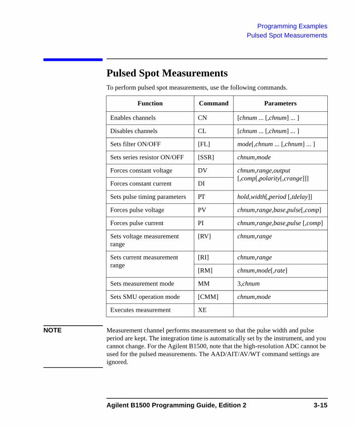
Programming ExamplesPulsed Spot Measurements
Pulsed Spot Measurements To perform pulsed spot measurements, use the following commands.
NOTE Measurement channel performs measurement so that the pulse width and pulse period are kept. The integration time is automatically set by the instrument, and you cannot change. For the Agilent B1500, note that the high-resolution ADC cannot be used for the pulsed measurements. The AAD/AIT/AV/WT command settings are ignored.
Function Command Parameters
Enables channels CN [chnum ... [,chnum] ... ]
Disables channels CL [chnum ... [,chnum] ... ]
Sets filter ON/OFF [FL] mode[,chnum ... [,chnum] ... ]
Sets series resistor ON/OFF [SSR] chnum,mode
Forces constant voltage DV chnum,range,output [,comp[,polarity[,crange]]]
Forces constant current DI
Sets pulse timing parameters PT hold,width[,period [,tdelay]]
Forces pulse voltage PV chnum,range,base,pulse[,comp]
Forces pulse current PI chnum,range,base,pulse [,comp]
Sets voltage measurement range
[RV] chnum,range
Sets current measurement range
[RI] chnum,range
[RM] chnum,mode[,rate]
Sets measurement mode MM 3,chnum
Sets SMU operation mode [CMM] chnum,mode
Executes measurement XE
Agilent B1500 Programming Guide, Edition 2 3-15
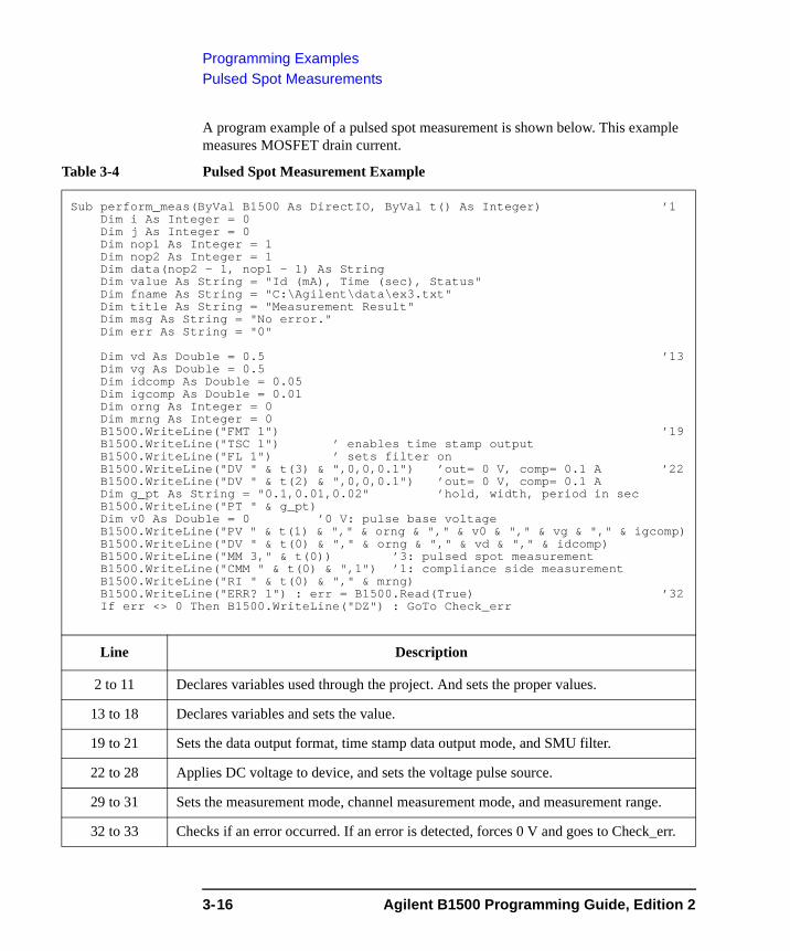
Programming ExamplesPulsed Spot Measurements
A program example of a pulsed spot measurement is shown below. This example measures MOSFET drain current.
Table 3-4 Pulsed Spot Measurement Example
Sub perform_meas(ByVal B1500 As DirectIO, ByVal t() As Integer) ’1Dim i As Integer = 0Dim j As Integer = 0Dim nop1 As Integer = 1Dim nop2 As Integer = 1Dim data(nop2 - 1, nop1 - 1) As StringDim value As String = "Id (mA), Time (sec), Status"Dim fname As String = "C:\Agilent\data\ex3.txt"Dim title As String = "Measurement Result"Dim msg As String = "No error."Dim err As String = "0"
Dim vd As Double = 0.5 ’13Dim vg As Double = 0.5Dim idcomp As Double = 0.05Dim igcomp As Double = 0.01Dim orng As Integer = 0Dim mrng As Integer = 0B1500.WriteLine("FMT 1") ’19B1500.WriteLine("TSC 1") ’ enables time stamp outputB1500.WriteLine("FL 1") ’ sets filter onB1500.WriteLine("DV " & t(3) & ",0,0,0.1") ’out= 0 V, comp= 0.1 A ’22B1500.WriteLine("DV " & t(2) & ",0,0,0.1") ’out= 0 V, comp= 0.1 ADim g_pt As String = "0.1,0.01,0.02" ’hold, width, period in secB1500.WriteLine("PT " & g_pt)Dim v0 As Double = 0 ’0 V: pulse base voltageB1500.WriteLine("PV " & t(1) & "," & orng & "," & v0 & "," & vg & "," & igcomp)B1500.WriteLine("DV " & t(0) & "," & orng & "," & vd & "," & idcomp)B1500.WriteLine("MM 3," & t(0)) ’3: pulsed spot measurementB1500.WriteLine("CMM " & t(0) & ",1") ’1: compliance side measurementB1500.WriteLine("RI " & t(0) & "," & mrng)B1500.WriteLine("ERR? 1") : err = B1500.Read(True) ’32If err <> 0 Then B1500.WriteLine("DZ") : GoTo Check_err
Line Description
2 to 11 Declares variables used through the project. And sets the proper values.
13 to 18 Declares variables and sets the value.
19 to 21 Sets the data output format, time stamp data output mode, and SMU filter.
22 to 28 Applies DC voltage to device, and sets the voltage pulse source.
29 to 31 Sets the measurement mode, channel measurement mode, and measurement range.
32 to 33 Checks if an error occurred. If an error is detected, forces 0 V and goes to Check_err.
3-16 Agilent B1500 Programming Guide, Edition 2
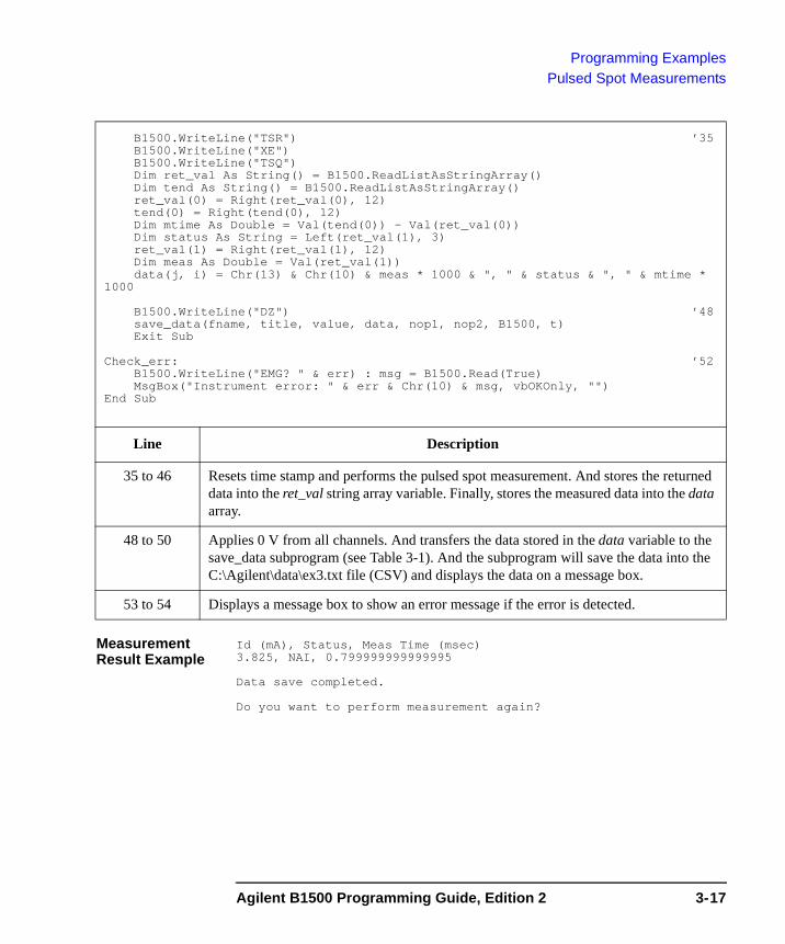
Programming ExamplesPulsed Spot Measurements
Measurement Result Example
Id (mA), Status, Meas Time (msec)3.825, NAI, 0.799999999999995
Data save completed.
Do you want to perform measurement again?
B1500.WriteLine("TSR") ’35B1500.WriteLine("XE")B1500.WriteLine("TSQ")Dim ret_val As String() = B1500.ReadListAsStringArray()Dim tend As String() = B1500.ReadListAsStringArray()ret_val(0) = Right(ret_val(0), 12)tend(0) = Right(tend(0), 12)Dim mtime As Double = Val(tend(0)) - Val(ret_val(0))Dim status As String = Left(ret_val(1), 3)ret_val(1) = Right(ret_val(1), 12)Dim meas As Double = Val(ret_val(1))data(j, i) = Chr(13) & Chr(10) & meas * 1000 & ", " & status & ", " & mtime *
1000
B1500.WriteLine("DZ") ’48save_data(fname, title, value, data, nop1, nop2, B1500, t)Exit Sub
Check_err: ’52B1500.WriteLine("EMG? " & err) : msg = B1500.Read(True)MsgBox("Instrument error: " & err & Chr(10) & msg, vbOKOnly, "")
End Sub
Line Description
35 to 46 Resets time stamp and performs the pulsed spot measurement. And stores the returned data into the ret_val string array variable. Finally, stores the measured data into the data array.
48 to 50 Applies 0 V from all channels. And transfers the data stored in the data variable to the save_data subprogram (see Table 3-1). And the subprogram will save the data into the C:\Agilent\data\ex3.txt file (CSV) and displays the data on a message box.
53 to 54 Displays a message box to show an error message if the error is detected.
Agilent B1500 Programming Guide, Edition 2 3-17

Programming ExamplesStaircase Sweep Measurements
Staircase Sweep Measurements To perform staircase sweep measurements, use the following commands.
NOTE If you use multiple measurement channels, the channels start measurement in the order defined in the MM command.
Function Command Parameters
Enables channels CN [chnum ... [,chnum] ... ]Disables channels CL [chnum ... [,chnum] ... ]Sets filter ON/OFF [FL] mode[,chnum ... [,chnum] ... ]Sets series resistor ON/OFF [SSR] chnum,modeSets integration time (Agilent B1500 can use AAD/AIT instead of AV.)
[AV] number[,mode][AAD] chnum[,type][AIT] type,mode[,N]
Sets sweep source timing parameter
[WT] hold,delay [,sdelay[,tdelay[,mdelay]]]
Sets auto abort function [WM] abort[,post]Sets voltage sweep source WV chnum,mode,range,start,stop,step
[,comp[,Pcomp]]Sets current sweep source WISets synchronous sweep source a
a. The WSV/WSI command must be entered after the WV/WI command.
[WSV] chnum,range,start,stop [,comp[,Pcomp]][WSI]
Forces constant voltage DV chnum,range,output [,comp[,polarity[,crange]]]Forces constant current DI
Sets voltage measurement range
[RV] chnum,range
Sets current measurement range
[RI] chnum,range[RM] chnum,mode[,rate]
Sets measurement mode MM 2,chnum[,chnum ... [,chnum] ... ]Sets SMU operation mode [CMM] chnum,modeExecutes measurement XE
3-18 Agilent B1500 Programming Guide, Edition 2
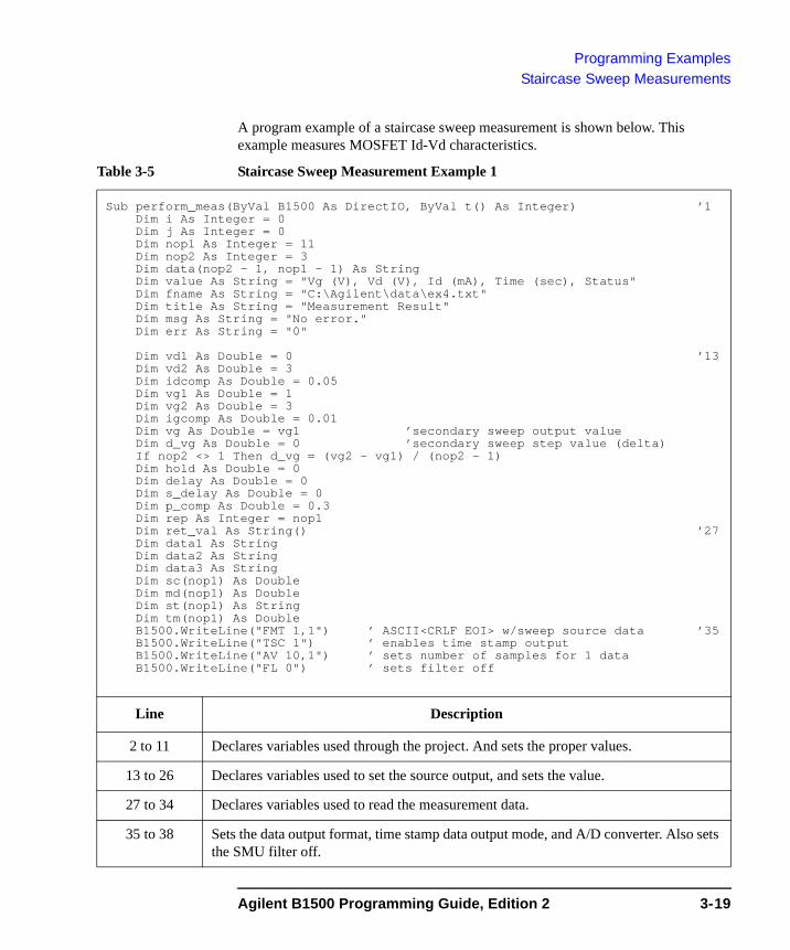
Programming ExamplesStaircase Sweep Measurements
A program example of a staircase sweep measurement is shown below. This example measures MOSFET Id-Vd characteristics.
Table 3-5 Staircase Sweep Measurement Example 1
Sub perform_meas(ByVal B1500 As DirectIO, ByVal t() As Integer) ’1Dim i As Integer = 0Dim j As Integer = 0Dim nop1 As Integer = 11Dim nop2 As Integer = 3Dim data(nop2 - 1, nop1 - 1) As StringDim value As String = "Vg (V), Vd (V), Id (mA), Time (sec), Status"Dim fname As String = "C:\Agilent\data\ex4.txt"Dim title As String = "Measurement Result"Dim msg As String = "No error."Dim err As String = "0"
Dim vd1 As Double = 0 ’13Dim vd2 As Double = 3Dim idcomp As Double = 0.05Dim vg1 As Double = 1Dim vg2 As Double = 3Dim igcomp As Double = 0.01Dim vg As Double = vg1 ’secondary sweep output valueDim d_vg As Double = 0 ’secondary sweep step value (delta)If nop2 <> 1 Then d_vg = (vg2 - vg1) / (nop2 - 1)Dim hold As Double = 0Dim delay As Double = 0Dim s_delay As Double = 0Dim p_comp As Double = 0.3Dim rep As Integer = nop1Dim ret_val As String() ’27Dim data1 As StringDim data2 As StringDim data3 As StringDim sc(nop1) As DoubleDim md(nop1) As DoubleDim st(nop1) As StringDim tm(nop1) As DoubleB1500.WriteLine("FMT 1,1") ’ ASCII<CRLF EOI> w/sweep source data ’35B1500.WriteLine("TSC 1") ’ enables time stamp outputB1500.WriteLine("AV 10,1") ’ sets number of samples for 1 dataB1500.WriteLine("FL 0") ’ sets filter off
Line Description
2 to 11 Declares variables used through the project. And sets the proper values.
13 to 26 Declares variables used to set the source output, and sets the value.
27 to 34 Declares variables used to read the measurement data.
35 to 38 Sets the data output format, time stamp data output mode, and A/D converter. Also sets the SMU filter off.
Agilent B1500 Programming Guide, Edition 2 3-19
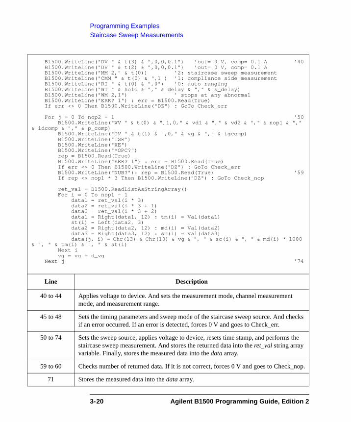
Programming ExamplesStaircase Sweep Measurements
B1500.WriteLine("DV " & t(3) & ",0,0,0.1") ’out= 0 V, comp= 0.1 A ’40B1500.WriteLine("DV " & t(2) & ",0,0,0.1") ’out= 0 V, comp= 0.1 AB1500.WriteLine("MM 2," & t(0)) ’2: staircase sweep measurementB1500.WriteLine("CMM " & t(0) & ",1") ’1: compliance side measurementB1500.WriteLine("RI " & t(0) & ",0") ’0: auto rangingB1500.WriteLine("WT " & hold & "," & delay & "," & s_delay)B1500.WriteLine("WM 2,1") ’ stops at any abnormalB1500.WriteLine("ERR? 1") : err = B1500.Read(True)If err <> 0 Then B1500.WriteLine("DZ") : GoTo Check_err
For j = 0 To nop2 - 1 ’50B1500.WriteLine("WV " & t(0) & ",1,0," & vd1 & "," & vd2 & "," & nop1 & ","
& idcomp & "," & p_comp)B1500.WriteLine("DV " & t(1) & ",0," & vg & "," & igcomp)B1500.WriteLine("TSR")B1500.WriteLine("XE")B1500.WriteLine("*OPC?")rep = B1500.Read(True)B1500.WriteLine("ERR? 1") : err = B1500.Read(True)If err <> 0 Then B1500.WriteLine("DZ") : GoTo Check_errB1500.WriteLine("NUB?"): rep = B1500.Read(True) ’59If rep <> nop1 * 3 Then B1500.WriteLine("DZ") : GoTo Check_nop
ret_val = B1500.ReadListAsStringArray()For i = 0 To nop1 - 1
data1 = ret_val(i * 3)data2 = ret_val(i * 3 + 1)data3 = ret_val(i * 3 + 2)data1 = Right(data1, 12) : tm(i) = Val(data1)st(i) = Left(data2, 3)data2 = Right(data2, 12) : md(i) = Val(data2)data3 = Right(data3, 12) : sc(i) = Val(data3)data(j, i) = Chr(13) & Chr(10) & vg & ", " & sc(i) & ", " & md(i) * 1000
& ", " & tm(i) & ", " & st(i)Next ivg = vg + d_vg
Next j ’74
Line Description
40 to 44 Applies voltage to device. And sets the measurement mode, channel measurement mode, and measurement range.
45 to 48 Sets the timing parameters and sweep mode of the staircase sweep source. And checks if an error occurred. If an error is detected, forces 0 V and goes to Check_err.
50 to 74 Sets the sweep source, applies voltage to device, resets time stamp, and performs the staircase sweep measurement. And stores the returned data into the ret_val string array variable. Finally, stores the measured data into the data array.
59 to 60 Checks number of returned data. If it is not correct, forces 0 V and goes to Check_nop.
71 Stores the measured data into the data array.
3-20 Agilent B1500 Programming Guide, Edition 2
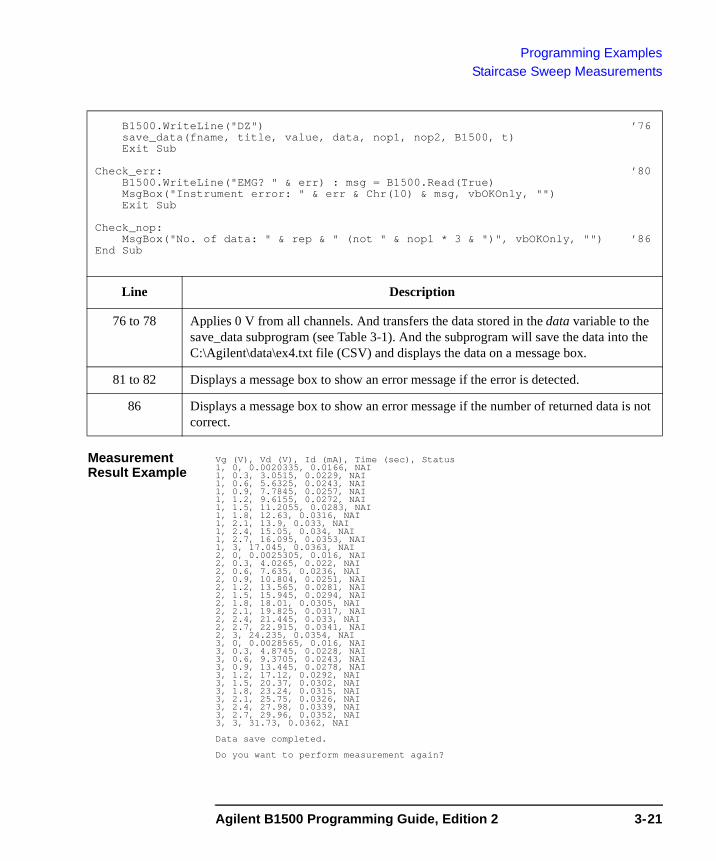
Programming ExamplesStaircase Sweep Measurements
Measurement Result Example
Vg (V), Vd (V), Id (mA), Time (sec), Status1, 0, 0.0020335, 0.0166, NAI1, 0.3, 3.0515, 0.0229, NAI1, 0.6, 5.6325, 0.0243, NAI1, 0.9, 7.7845, 0.0257, NAI1, 1.2, 9.6155, 0.0272, NAI1, 1.5, 11.2055, 0.0283, NAI1, 1.8, 12.63, 0.0316, NAI1, 2.1, 13.9, 0.033, NAI1, 2.4, 15.05, 0.034, NAI1, 2.7, 16.095, 0.0353, NAI1, 3, 17.045, 0.0363, NAI2, 0, 0.0025305, 0.016, NAI2, 0.3, 4.0265, 0.022, NAI2, 0.6, 7.635, 0.0236, NAI2, 0.9, 10.804, 0.0251, NAI2, 1.2, 13.565, 0.0281, NAI2, 1.5, 15.945, 0.0294, NAI2, 1.8, 18.01, 0.0305, NAI2, 2.1, 19.825, 0.0317, NAI2, 2.4, 21.445, 0.033, NAI2, 2.7, 22.915, 0.0341, NAI2, 3, 24.235, 0.0354, NAI3, 0, 0.0028565, 0.016, NAI3, 0.3, 4.8745, 0.0228, NAI3, 0.6, 9.3705, 0.0243, NAI3, 0.9, 13.445, 0.0278, NAI3, 1.2, 17.12, 0.0292, NAI3, 1.5, 20.37, 0.0302, NAI3, 1.8, 23.24, 0.0315, NAI3, 2.1, 25.75, 0.0326, NAI3, 2.4, 27.98, 0.0339, NAI3, 2.7, 29.96, 0.0352, NAI3, 3, 31.73, 0.0362, NAI
Data save completed.
Do you want to perform measurement again?
B1500.WriteLine("DZ") ’76save_data(fname, title, value, data, nop1, nop2, B1500, t)Exit Sub
Check_err: ’80B1500.WriteLine("EMG? " & err) : msg = B1500.Read(True)MsgBox("Instrument error: " & err & Chr(10) & msg, vbOKOnly, "")Exit Sub
Check_nop:MsgBox("No. of data: " & rep & " (not " & nop1 * 3 & ")", vbOKOnly, "") ’86
End Sub
Line Description
76 to 78 Applies 0 V from all channels. And transfers the data stored in the data variable to the save_data subprogram (see Table 3-1). And the subprogram will save the data into the C:\Agilent\data\ex4.txt file (CSV) and displays the data on a message box.
81 to 82 Displays a message box to show an error message if the error is detected.
86 Displays a message box to show an error message if the number of returned data is not correct.
Agilent B1500 Programming Guide, Edition 2 3-21
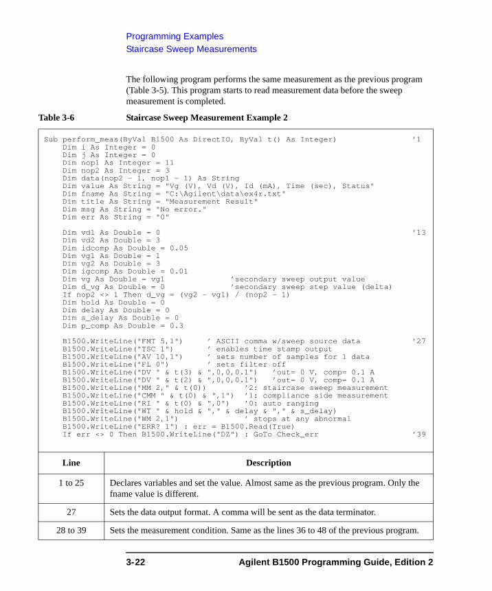
Programming ExamplesStaircase Sweep Measurements
The following program performs the same measurement as the previous program (Table 3-5). This program starts to read measurement data before the sweep measurement is completed.
Table 3-6 Staircase Sweep Measurement Example 2
Sub perform_meas(ByVal B1500 As DirectIO, ByVal t() As Integer) ’1Dim i As Integer = 0Dim j As Integer = 0Dim nop1 As Integer = 11Dim nop2 As Integer = 3Dim data(nop2 - 1, nop1 - 1) As StringDim value As String = "Vg (V), Vd (V), Id (mA), Time (sec), Status"Dim fname As String = "C:\Agilent\data\ex4r.txt"Dim title As String = "Measurement Result"Dim msg As String = "No error."Dim err As String = "0"
Dim vd1 As Double = 0 ’13Dim vd2 As Double = 3Dim idcomp As Double = 0.05Dim vg1 As Double = 1Dim vg2 As Double = 3Dim igcomp As Double = 0.01Dim vg As Double = vg1 ’secondary sweep output valueDim d_vg As Double = 0 ’secondary sweep step value (delta)If nop2 <> 1 Then d_vg = (vg2 - vg1) / (nop2 - 1)Dim hold As Double = 0Dim delay As Double = 0Dim s_delay As Double = 0Dim p_comp As Double = 0.3
B1500.WriteLine("FMT 5,1") ’ ASCII comma w/sweep source data ’27B1500.WriteLine("TSC 1") ’ enables time stamp outputB1500.WriteLine("AV 10,1") ’ sets number of samples for 1 dataB1500.WriteLine("FL 0") ’ sets filter offB1500.WriteLine("DV " & t(3) & ",0,0,0.1") ’out= 0 V, comp= 0.1 AB1500.WriteLine("DV " & t(2) & ",0,0,0.1") ’out= 0 V, comp= 0.1 AB1500.WriteLine("MM 2," & t(0)) ’2: staircase sweep measurementB1500.WriteLine("CMM " & t(0) & ",1") ’1: compliance side measurementB1500.WriteLine("RI " & t(0) & ",0") ’0: auto rangingB1500.WriteLine("WT " & hold & "," & delay & "," & s_delay)B1500.WriteLine("WM 2,1") ’ stops at any abnormalB1500.WriteLine("ERR? 1") : err = B1500.Read(True)If err <> 0 Then B1500.WriteLine("DZ") : GoTo Check_err ’39
Line Description
1 to 25 Declares variables and set the value. Almost same as the previous program. Only the fname value is different.
27 Sets the data output format. A comma will be sent as the data terminator.
28 to 39 Sets the measurement condition. Same as the lines 36 to 48 of the previous program.
3-22 Agilent B1500 Programming Guide, Edition 2
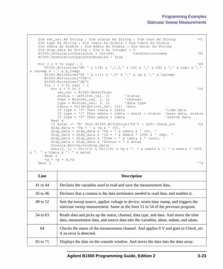
Programming ExamplesStaircase Sweep Measurements
Dim ret_val As String : Dim status As String : Dim chan As String ’41Dim type As String : Dim rdata As Double : Dim tdata As DoubleDim sdata As Double : Dim mdata As Double : Dim mstat As StringDim disp_data As String : Dim k As Integer = 0B1500.TerminationCharacter = Chr(44) ’terminator=comma ’45B1500.TerminationCharacterEnabled = True
For j = 0 To nop2 - 1 ’48B1500.WriteLine("WV " & t(0) & ",1,0," & vd1 & "," & vd2 & "," & nop1 & ","
& idcomp & "," & p_comp)B1500.WriteLine("DV " & t(1) & ",0" & "," & vg & "," & igcomp)B1500.WriteLine("TSR")B1500.WriteLine("XE")For i = 0 To nop1 - 1
For k = 0 To 2 ’54ret_val = B1500.Read(True)status = Left(ret_val, 1) ’statuschan = Mid(ret_val, 2, 1) ’channeltype = Mid(ret_val, 3, 1) ’data typerdata = Val(Right(ret_val, 12)) ’dataIf type = "T" Then tdata = rdata ’time dataIf type = "I" Then mdata = rdata : mstat = status ’meas data, statusIf type = "V" Then sdata = rdata ’source data
Next kIf mstat <> "N" Then B1500.WriteLine("DZ") : GoTo Check_err ’64disp_data = "Vg = " & vg & " (V), "disp_data = disp_data & "Vd = " & sdata & " (V), "disp_data = disp_data & "Id = " & mdata * 1000 & " (mA), "disp_data = disp_data & "Time = " & tdata & " (sec), "disp_data = disp_data & "Status = " & mstatConsole.WriteLine(disp_data)data(j, i) = Chr(13) & Chr(10) & vg & ", " & sdata & ", " & mdata * 1000
& ", " & tdata & ", " & mstatNext ivg = vg + d_vg
Next j ’74
Line Description
41 to 44 Declares the variables used to read and save the measurement data.
45 to 46 Declares that a comma is the data terminator needed to read data, and enables it.
49 to 52 Sets the sweep source, applies voltage to device, resets time stamp, and triggers the staircase sweep measurement. Same as the lines 51 to 54 of the previous program.
54 to 63 Reads data and picks up the status, channel, data type, and data. And stores the time data, measurement data, and source data into the variables, tdata, mdata, and sdata.
64 Checks the status of the measurement channel. And applies 0 V and goes to Check_err if an error is detected.
65 to 71 Displays the data on the console window. And stores the data into the data array.
Agilent B1500 Programming Guide, Edition 2 3-23
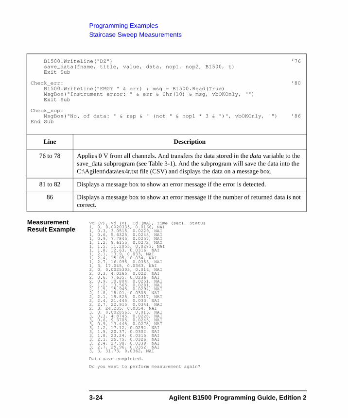
Programming ExamplesStaircase Sweep Measurements
Measurement Result Example
Vg (V), Vd (V), Id (mA), Time (sec), Status1, 0, 0.0020335, 0.0166, NAI1, 0.3, 3.0515, 0.0229, NAI1, 0.6, 5.6325, 0.0243, NAI1, 0.9, 7.7845, 0.0257, NAI1, 1.2, 9.6155, 0.0272, NAI1, 1.5, 11.2055, 0.0283, NAI1, 1.8, 12.63, 0.0316, NAI1, 2.1, 13.9, 0.033, NAI1, 2.4, 15.05, 0.034, NAI1, 2.7, 16.095, 0.0353, NAI1, 3, 17.045, 0.0363, NAI2, 0, 0.0025305, 0.016, NAI2, 0.3, 4.0265, 0.022, NAI2, 0.6, 7.635, 0.0236, NAI2, 0.9, 10.804, 0.0251, NAI2, 1.2, 13.565, 0.0281, NAI2, 1.5, 15.945, 0.0294, NAI2, 1.8, 18.01, 0.0305, NAI2, 2.1, 19.825, 0.0317, NAI2, 2.4, 21.445, 0.033, NAI2, 2.7, 22.915, 0.0341, NAI2, 3, 24.235, 0.0354, NAI3, 0, 0.0028565, 0.016, NAI3, 0.3, 4.8745, 0.0228, NAI3, 0.6, 9.3705, 0.0243, NAI3, 0.9, 13.445, 0.0278, NAI3, 1.2, 17.12, 0.0292, NAI3, 1.5, 20.37, 0.0302, NAI3, 1.8, 23.24, 0.0315, NAI3, 2.1, 25.75, 0.0326, NAI3, 2.4, 27.98, 0.0339, NAI3, 2.7, 29.96, 0.0352, NAI3, 3, 31.73, 0.0362, NAI
Data save completed.
Do you want to perform measurement again?
B1500.WriteLine("DZ") ’76save_data(fname, title, value, data, nop1, nop2, B1500, t)Exit Sub
Check_err: ’80B1500.WriteLine("EMG? " & err) : msg = B1500.Read(True)MsgBox("Instrument error: " & err & Chr(10) & msg, vbOKOnly, "")Exit Sub
Check_nop:MsgBox("No. of data: " & rep & " (not " & nop1 * 3 & ")", vbOKOnly, "") ’86
End Sub
Line Description
76 to 78 Applies 0 V from all channels. And transfers the data stored in the data variable to the save_data subprogram (see Table 3-1). And the subprogram will save the data into the C:\Agilent\data\ex4r.txt file (CSV) and displays the data on a message box.
81 to 82 Displays a message box to show an error message if the error is detected.
86 Displays a message box to show an error message if the number of returned data is not correct.
3-24 Agilent B1500 Programming Guide, Edition 2
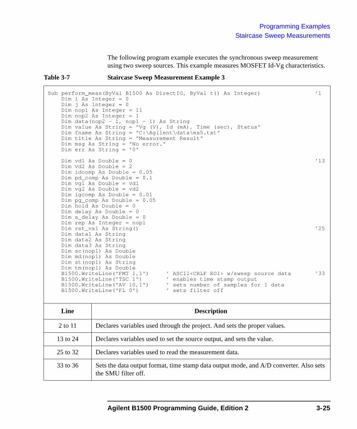
Programming ExamplesStaircase Sweep Measurements
The following program example executes the synchronous sweep measurement using two sweep sources. This example measures MOSFET Id-Vg characteristics.
Table 3-7 Staircase Sweep Measurement Example 3
Sub perform_meas(ByVal B1500 As DirectIO, ByVal t() As Integer) ’1Dim i As Integer = 0Dim j As Integer = 0Dim nop1 As Integer = 11Dim nop2 As Integer = 1Dim data(nop2 - 1, nop1 - 1) As StringDim value As String = "Vg (V), Id (mA), Time (sec), Status"Dim fname As String = "C:\Agilent\data\ex5.txt"Dim title As String = "Measurement Result"Dim msg As String = "No error."Dim err As String = "0"
Dim vd1 As Double = 0 ’13Dim vd2 As Double = 2Dim idcomp As Double = 0.05Dim pd_comp As Double = 0.1Dim vg1 As Double = vd1Dim vg2 As Double = vd2Dim igcomp As Double = 0.01Dim pg_comp As Double = 0.05Dim hold As Double = 0Dim delay As Double = 0Dim s_delay As Double = 0Dim rep As Integer = nop1Dim ret_val As String() ’25Dim data1 As StringDim data2 As StringDim data3 As StringDim sc(nop1) As DoubleDim md(nop1) As DoubleDim st(nop1) As StringDim tm(nop1) As DoubleB1500.WriteLine("FMT 1,1") ’ ASCII<CRLF EOI> w/sweep source data ’33B1500.WriteLine("TSC 1") ’ enables time stamp outputB1500.WriteLine("AV 10,1") ’ sets number of samples for 1 dataB1500.WriteLine("FL 0") ’ sets filter off
Line Description
2 to 11 Declares variables used through the project. And sets the proper values.
13 to 24 Declares variables used to set the source output, and sets the value.
25 to 32 Declares variables used to read the measurement data.
33 to 36 Sets the data output format, time stamp data output mode, and A/D converter. Also sets the SMU filter off.
Agilent B1500 Programming Guide, Edition 2 3-25
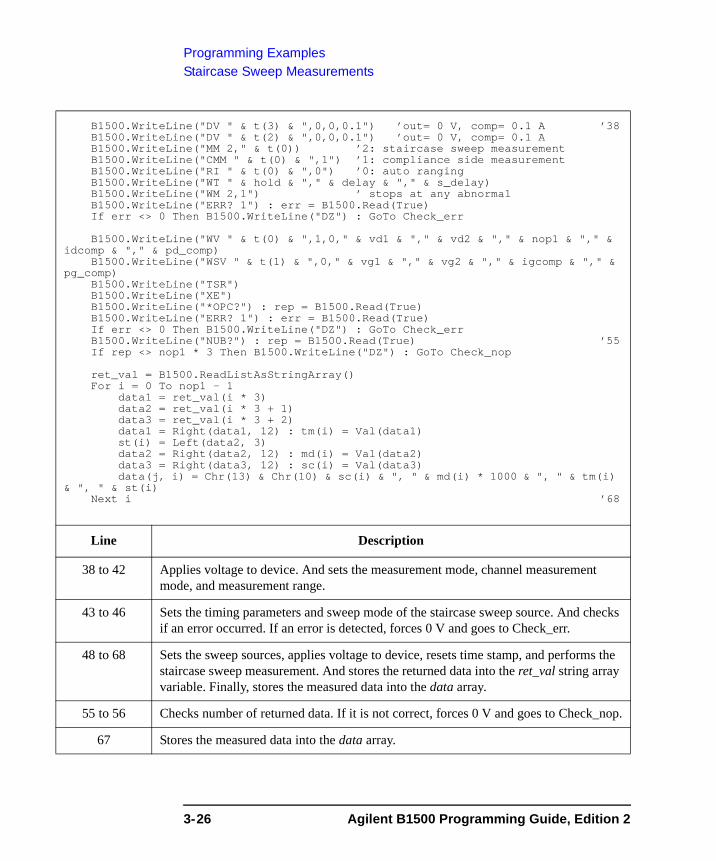
Programming ExamplesStaircase Sweep Measurements
B1500.WriteLine("DV " & t(3) & ",0,0,0.1") ’out= 0 V, comp= 0.1 A ’38B1500.WriteLine("DV " & t(2) & ",0,0,0.1") ’out= 0 V, comp= 0.1 AB1500.WriteLine("MM 2," & t(0)) ’2: staircase sweep measurementB1500.WriteLine("CMM " & t(0) & ",1") ’1: compliance side measurementB1500.WriteLine("RI " & t(0) & ",0") ’0: auto rangingB1500.WriteLine("WT " & hold & "," & delay & "," & s_delay)B1500.WriteLine("WM 2,1") ’ stops at any abnormalB1500.WriteLine("ERR? 1") : err = B1500.Read(True)If err <> 0 Then B1500.WriteLine("DZ") : GoTo Check_err
B1500.WriteLine("WV " & t(0) & ",1,0," & vd1 & "," & vd2 & "," & nop1 & "," & idcomp & "," & pd_comp)
B1500.WriteLine("WSV " & t(1) & ",0," & vg1 & "," & vg2 & "," & igcomp & "," & pg_comp)
B1500.WriteLine("TSR")B1500.WriteLine("XE")B1500.WriteLine("*OPC?") : rep = B1500.Read(True)B1500.WriteLine("ERR? 1") : err = B1500.Read(True)If err <> 0 Then B1500.WriteLine("DZ") : GoTo Check_errB1500.WriteLine("NUB?") : rep = B1500.Read(True) ’55If rep <> nop1 * 3 Then B1500.WriteLine("DZ") : GoTo Check_nop
ret_val = B1500.ReadListAsStringArray()For i = 0 To nop1 - 1
data1 = ret_val(i * 3)data2 = ret_val(i * 3 + 1)data3 = ret_val(i * 3 + 2)data1 = Right(data1, 12) : tm(i) = Val(data1)st(i) = Left(data2, 3)data2 = Right(data2, 12) : md(i) = Val(data2)data3 = Right(data3, 12) : sc(i) = Val(data3)data(j, i) = Chr(13) & Chr(10) & sc(i) & ", " & md(i) * 1000 & ", " & tm(i)
& ", " & st(i)Next i ’68
Line Description
38 to 42 Applies voltage to device. And sets the measurement mode, channel measurement mode, and measurement range.
43 to 46 Sets the timing parameters and sweep mode of the staircase sweep source. And checks if an error occurred. If an error is detected, forces 0 V and goes to Check_err.
48 to 68 Sets the sweep sources, applies voltage to device, resets time stamp, and performs the staircase sweep measurement. And stores the returned data into the ret_val string array variable. Finally, stores the measured data into the data array.
55 to 56 Checks number of returned data. If it is not correct, forces 0 V and goes to Check_nop.
67 Stores the measured data into the data array.
3-26 Agilent B1500 Programming Guide, Edition 2
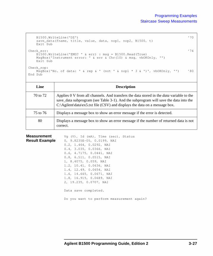
Programming ExamplesStaircase Sweep Measurements
Measurement Result Example
Vg (V), Id (mA), Time (sec), Status0, 9.8235E-05, 0.0199, NAI0.2, 1.464, 0.0292, NAI0.4, 3.035, 0.0366, NAI0.6, 4.7175, 0.0441, NAI0.8, 6.511, 0.0515, NAI1, 8.4075, 0.059, NAI1.2, 10.41, 0.0636, NAI1.4, 12.49, 0.0654, NAI1.6, 14.665, 0.0671, NAI1.8, 16.915, 0.0689, NAI2, 19.235, 0.0707, NAI
Data save completed.
Do you want to perform measurement again?
B1500.WriteLine("DZ") ’70save_data(fname, title, value, data, nop1, nop2, B1500, t)Exit Sub
Check_err: ’74B1500.WriteLine("EMG? " & err) : msg = B1500.Read(True)MsgBox("Instrument error: " & err & Chr(10) & msg, vbOKOnly, "")Exit Sub
Check_nop:MsgBox("No. of data: " & rep & " (not " & nop1 * 3 & ")", vbOKOnly, "") ’80
End Sub
Line Description
70 to 72 Applies 0 V from all channels. And transfers the data stored in the data variable to the save_data subprogram (see Table 3-1). And the subprogram will save the data into the C:\Agilent\data\ex5.txt file (CSV) and displays the data on a message box.
75 to 76 Displays a message box to show an error message if the error is detected.
80 Displays a message box to show an error message if the number of returned data is not correct.
Agilent B1500 Programming Guide, Edition 2 3-27
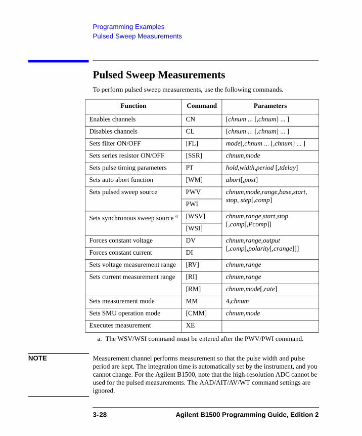
Programming ExamplesPulsed Sweep Measurements
Pulsed Sweep Measurements To perform pulsed sweep measurements, use the following commands.
NOTE Measurement channel performs measurement so that the pulse width and pulse period are kept. The integration time is automatically set by the instrument, and you cannot change. For the Agilent B1500, note that the high-resolution ADC cannot be used for the pulsed measurements. The AAD/AIT/AV/WT command settings are ignored.
Function Command Parameters
Enables channels CN [chnum ... [,chnum] ... ]
Disables channels CL [chnum ... [,chnum] ... ]
Sets filter ON/OFF [FL] mode[,chnum ... [,chnum] ... ]
Sets series resistor ON/OFF [SSR] chnum,mode
Sets pulse timing parameters PT hold,width,period [,tdelay]
Sets auto abort function [WM] abort[,post]
Sets pulsed sweep source PWV chnum,mode,range,base,start, stop, step[,comp]PWI
Sets synchronous sweep source a [WSV] chnum,range,start,stop [,comp[,Pcomp]][WSI]
Forces constant voltage DV chnum,range,output [,comp[,polarity[,crange]]]Forces constant current DI
Sets voltage measurement range [RV] chnum,range
Sets current measurement range [RI] chnum,range
[RM] chnum,mode[,rate]
Sets measurement mode MM 4,chnum
Sets SMU operation mode [CMM] chnum,mode
Executes measurement XE
a. The WSV/WSI command must be entered after the PWV/PWI command.
3-28 Agilent B1500 Programming Guide, Edition 2
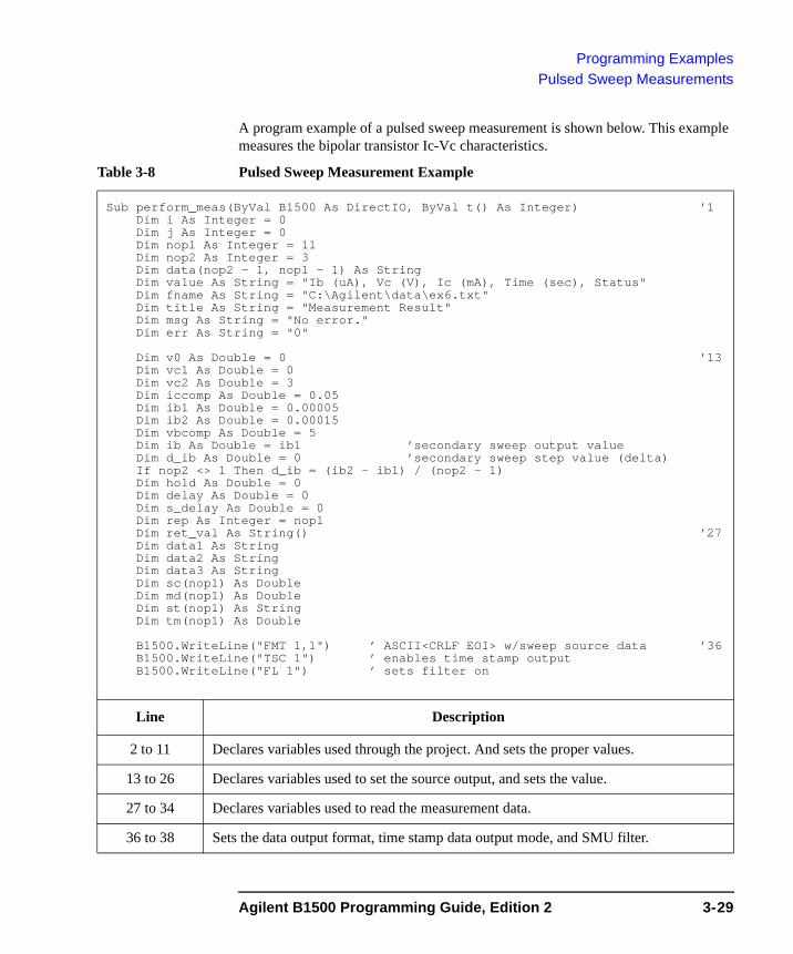
Programming ExamplesPulsed Sweep Measurements
A program example of a pulsed sweep measurement is shown below. This example measures the bipolar transistor Ic-Vc characteristics.
Table 3-8 Pulsed Sweep Measurement Example
Sub perform_meas(ByVal B1500 As DirectIO, ByVal t() As Integer) ’1Dim i As Integer = 0Dim j As Integer = 0Dim nop1 As Integer = 11Dim nop2 As Integer = 3Dim data(nop2 - 1, nop1 - 1) As StringDim value As String = "Ib (uA), Vc (V), Ic (mA), Time (sec), Status"Dim fname As String = "C:\Agilent\data\ex6.txt"Dim title As String = "Measurement Result"Dim msg As String = "No error."Dim err As String = "0"
Dim v0 As Double = 0 ’13Dim vc1 As Double = 0Dim vc2 As Double = 3Dim iccomp As Double = 0.05Dim ib1 As Double = 0.00005Dim ib2 As Double = 0.00015Dim vbcomp As Double = 5Dim ib As Double = ib1 ’secondary sweep output valueDim d_ib As Double = 0 ’secondary sweep step value (delta)If nop2 <> 1 Then d_ib = (ib2 - ib1) / (nop2 - 1)Dim hold As Double = 0Dim delay As Double = 0Dim s_delay As Double = 0Dim rep As Integer = nop1Dim ret_val As String() ’27Dim data1 As StringDim data2 As StringDim data3 As StringDim sc(nop1) As DoubleDim md(nop1) As DoubleDim st(nop1) As StringDim tm(nop1) As Double
B1500.WriteLine("FMT 1,1") ’ ASCII<CRLF EOI> w/sweep source data ’36B1500.WriteLine("TSC 1") ’ enables time stamp outputB1500.WriteLine("FL 1") ’ sets filter on
Line Description
2 to 11 Declares variables used through the project. And sets the proper values.
13 to 26 Declares variables used to set the source output, and sets the value.
27 to 34 Declares variables used to read the measurement data.
36 to 38 Sets the data output format, time stamp data output mode, and SMU filter.
Agilent B1500 Programming Guide, Edition 2 3-29
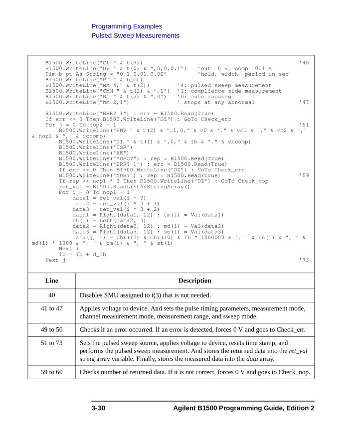
Programming ExamplesPulsed Sweep Measurements
B1500.WriteLine("CL " & t(3)) ’40B1500.WriteLine("DV " & t(0) & ",0,0,0.1") ’out= 0 V, comp= 0.1 ADim b_pt As String = "0.1,0.01,0.02" ’hold, width, period in secB1500.WriteLine("PT " & b_pt)B1500.WriteLine("MM 4," & t(2)) ’4: pulsed sweep measurementB1500.WriteLine("CMM " & t(2) & ",1") ’1: compliance side measurementB1500.WriteLine("RI " & t(2) & ",0") ’0: auto rangingB1500.WriteLine("WM 2,1") ’ stops at any abnormal ’47
B1500.WriteLine("ERR? 1") : err = B1500.Read(True)If err <> 0 Then B1500.WriteLine("DZ") : GoTo Check_errFor j = 0 To nop2 - 1 ’51
B1500.WriteLine("PWV " & t(2) & ",1,0," & v0 & "," & vc1 & "," & vc2 & "," & nop1 & "," & iccomp)
B1500.WriteLine("DI " & t(1) & ",0," & ib & "," & vbcomp)B1500.WriteLine("TSR")B1500.WriteLine("XE")B1500.WriteLine("*OPC?") : rep = B1500.Read(True)B1500.WriteLine("ERR? 1") : err = B1500.Read(True)If err <> 0 Then B1500.WriteLine("DZ") : GoTo Check_errB1500.WriteLine("NUB?") : rep = B1500.Read(True) ’59If rep <> nop1 * 3 Then B1500.WriteLine("DZ") : GoTo Check_nopret_val = B1500.ReadListAsStringArray()For i = 0 To nop1 - 1
data1 = ret_val(i * 3)data2 = ret_val(i * 3 + 1)data3 = ret_val(i * 3 + 2)data1 = Right(data1, 12) : tm(i) = Val(data1)st(i) = Left(data2, 3)data2 = Right(data2, 12) : md(i) = Val(data2)data3 = Right(data3, 12) : sc(i) = Val(data3)data(j, i) = Chr(13) & Chr(10) & ib * 1000000 & ", " & sc(i) & ", " &
md(i) * 1000 & ", " & tm(i) & ", " & st(i)Next iib = ib + d_ib
Next j ’73
Line Description
40 Disables SMU assigned to t(3) that is not needed.
41 to 47 Applies voltage to device. And sets the pulse timing parameters, measurement mode, channel measurement mode, measurement range, and sweep mode.
49 to 50 Checks if an error occurred. If an error is detected, forces 0 V and goes to Check_err.
51 to 73 Sets the pulsed sweep source, applies voltage to device, resets time stamp, and performs the pulsed sweep measurement. And stores the returned data into the ret_val string array variable. Finally, stores the measured data into the data array.
59 to 60 Checks number of returned data. If it is not correct, forces 0 V and goes to Check_nop.
3-30 Agilent B1500 Programming Guide, Edition 2

Programming ExamplesPulsed Sweep Measurements
Measurement Result Example
Ib (uA), Vc (V), Ic (mA), Time (sec), Status50, 0, -0.055, 0.1161, NDI50, 0.3, 8.98, 0.1361, NDI50, 0.6, 9.745, 0.1561, NDI50, 0.9, 9.77, 0.1761, NDI50, 1.2, 9.84, 0.1961, NDI50, 1.5, 9.87, 0.2161, NDI50, 1.8, 9.895, 0.2361, NDI50, 2.1, 9.96, 0.2561, NDI50, 2.4, 9.94, 0.2761, NDI50, 2.7, 9.955, 0.2961, NDI50, 3, 9.98, 0.3161, NDI100, 0, -0.1, 0.1129, NDI100, 0.3, 15.76, 0.1329, NDI100, 0.6, 18.2, 0.1529, NDI100, 0.9, 18.86, 0.1729, NDI100, 1.2, 18.99, 0.1929, NDI100, 1.5, 19.105, 0.2129, NDI100, 1.8, 19.17, 0.2329, NDI100, 2.1, 19.2, 0.2529, NDI100, 2.4, 19.27, 0.2729, NDI100, 2.7, 19.33, 0.2929, NDI100, 3, 19.395, 0.3129, NDI150, 0, -0.15, 0.1139, NDI150, 0.3, 21.055, 0.1339, NDI150, 0.6, 24.625, 0.1539, NDI150, 0.9, 26.595, 0.1739, NDI150, 1.2, 27.38, 0.1939, NDI150, 1.5, 27.625, 0.2139, NDI150, 1.8, 27.785, 0.2339, NDI150, 2.1, 27.915, 0.2539, NDI150, 2.4, 28.07, 0.2739, NDI150, 2.7, 28.18, 0.2939, NDI150, 3, 28.275, 0.3139, NDI
Data save completed.
Do you want to perform measurement again?
B1500.WriteLine("DZ") ’75save_data(fname, title, value, data, nop1, nop2, B1500, t)Exit Sub
Check_err: ’79B1500.WriteLine("EMG? " & err) : msg = B1500.Read(True)MsgBox("Instrument error: " & err & Chr(10) & msg, vbOKOnly, "")Exit Sub
Check_nop:MsgBox("No. of data: " & rep & " (not " & nop1 * 3 & ")", vbOKOnly, "") ’85
End Sub
Line Description
75 to 77 Applies 0 V from all channels. And transfers the data stored in the data variable to the save_data subprogram (see Table 3-1). And the subprogram will save the data into the C:\Agilent\data\ex6.txt file (CSV) and displays the data on a message box.
80 to 81 Displays a message box to show an error message if the error is detected.
85 Displays a message box to show an error message if the number of returned data is not correct.
Agilent B1500 Programming Guide, Edition 2 3-31
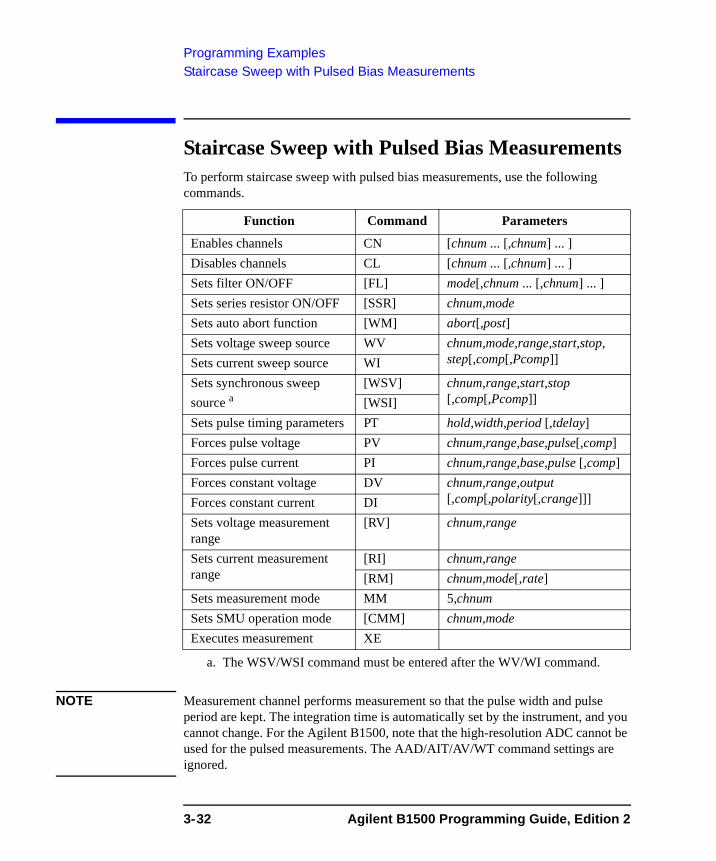
Programming ExamplesStaircase Sweep with Pulsed Bias Measurements
Staircase Sweep with Pulsed Bias Measurements To perform staircase sweep with pulsed bias measurements, use the following commands.
NOTE Measurement channel performs measurement so that the pulse width and pulse period are kept. The integration time is automatically set by the instrument, and you cannot change. For the Agilent B1500, note that the high-resolution ADC cannot be used for the pulsed measurements. The AAD/AIT/AV/WT command settings are ignored.
Function Command Parameters
Enables channels CN [chnum ... [,chnum] ... ]Disables channels CL [chnum ... [,chnum] ... ]Sets filter ON/OFF [FL] mode[,chnum ... [,chnum] ... ]Sets series resistor ON/OFF [SSR] chnum,modeSets auto abort function [WM] abort[,post]Sets voltage sweep source WV chnum,mode,range,start,stop,
step[,comp[,Pcomp]]Sets current sweep source WISets synchronous sweep source a
a. The WSV/WSI command must be entered after the WV/WI command.
[WSV] chnum,range,start,stop [,comp[,Pcomp]][WSI]
Sets pulse timing parameters PT hold,width,period [,tdelay]Forces pulse voltage PV chnum,range,base,pulse[,comp]Forces pulse current PI chnum,range,base,pulse [,comp]Forces constant voltage DV chnum,range,output
[,comp[,polarity[,crange]]]Forces constant current DISets voltage measurement range
[RV] chnum,range
Sets current measurement range
[RI] chnum,range[RM] chnum,mode[,rate]
Sets measurement mode MM 5,chnumSets SMU operation mode [CMM] chnum,modeExecutes measurement XE
3-32 Agilent B1500 Programming Guide, Edition 2
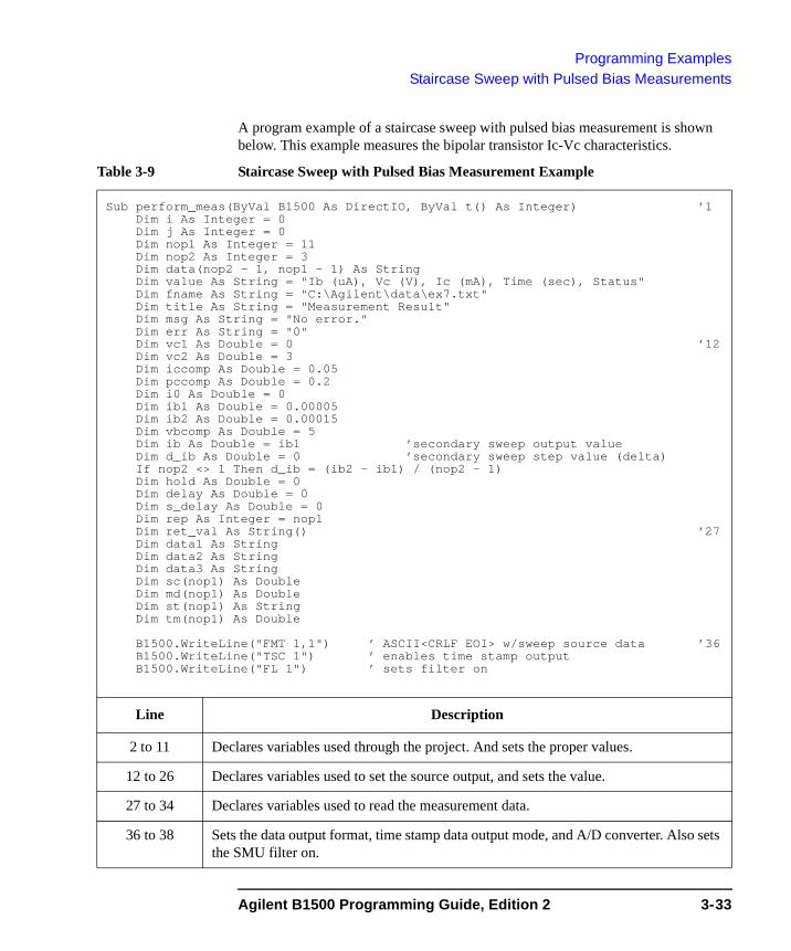
Programming ExamplesStaircase Sweep with Pulsed Bias Measurements
A program example of a staircase sweep with pulsed bias measurement is shown below. This example measures the bipolar transistor Ic-Vc characteristics.
Table 3-9 Staircase Sweep with Pulsed Bias Measurement Example
Sub perform_meas(ByVal B1500 As DirectIO, ByVal t() As Integer) ’1Dim i As Integer = 0Dim j As Integer = 0Dim nop1 As Integer = 11Dim nop2 As Integer = 3Dim data(nop2 - 1, nop1 - 1) As StringDim value As String = "Ib (uA), Vc (V), Ic (mA), Time (sec), Status"Dim fname As String = "C:\Agilent\data\ex7.txt"Dim title As String = "Measurement Result"Dim msg As String = "No error."Dim err As String = "0"Dim vc1 As Double = 0 ’12Dim vc2 As Double = 3Dim iccomp As Double = 0.05Dim pccomp As Double = 0.2Dim i0 As Double = 0Dim ib1 As Double = 0.00005Dim ib2 As Double = 0.00015Dim vbcomp As Double = 5Dim ib As Double = ib1 ’secondary sweep output valueDim d_ib As Double = 0 ’secondary sweep step value (delta)If nop2 <> 1 Then d_ib = (ib2 - ib1) / (nop2 - 1)Dim hold As Double = 0Dim delay As Double = 0Dim s_delay As Double = 0Dim rep As Integer = nop1Dim ret_val As String() ’27Dim data1 As StringDim data2 As StringDim data3 As StringDim sc(nop1) As DoubleDim md(nop1) As DoubleDim st(nop1) As StringDim tm(nop1) As Double
B1500.WriteLine("FMT 1,1") ’ ASCII<CRLF EOI> w/sweep source data ’36B1500.WriteLine("TSC 1") ’ enables time stamp outputB1500.WriteLine("FL 1") ’ sets filter on
Line Description
2 to 11 Declares variables used through the project. And sets the proper values.
12 to 26 Declares variables used to set the source output, and sets the value.
27 to 34 Declares variables used to read the measurement data.
36 to 38 Sets the data output format, time stamp data output mode, and A/D converter. Also sets the SMU filter on.
Agilent B1500 Programming Guide, Edition 2 3-33
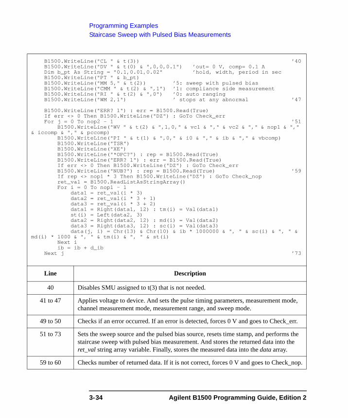
Programming ExamplesStaircase Sweep with Pulsed Bias Measurements
B1500.WriteLine("CL " & t(3)) ’40B1500.WriteLine("DV " & t(0) & ",0,0,0.1") ’out= 0 V, comp= 0.1 ADim b_pt As String = "0.1,0.01,0.02" ’hold, width, period in secB1500.WriteLine("PT " & b_pt)B1500.WriteLine("MM 5," & t(2)) ’5: sweep with pulsed biasB1500.WriteLine("CMM " & t(2) & ",1") ’1: compliance side measurementB1500.WriteLine("RI " & t(2) & ",0") ’0: auto rangingB1500.WriteLine("WM 2,1") ’ stops at any abnormal ’47
B1500.WriteLine("ERR? 1") : err = B1500.Read(True)If err <> 0 Then B1500.WriteLine("DZ") : GoTo Check_errFor j = 0 To nop2 - 1 ’51
B1500.WriteLine("WV " & t(2) & ",1,0," & vc1 & "," & vc2 & "," & nop1 & "," & iccomp & "," & pccomp)
B1500.WriteLine("PI " & t(1) & ",0," & i0 & "," & ib & "," & vbcomp)B1500.WriteLine("TSR")B1500.WriteLine("XE")B1500.WriteLine("*OPC?") : rep = B1500.Read(True)B1500.WriteLine("ERR? 1") : err = B1500.Read(True)If err <> 0 Then B1500.WriteLine("DZ") : GoTo Check_errB1500.WriteLine("NUB?") : rep = B1500.Read(True) ’59If rep <> nop1 * 3 Then B1500.WriteLine("DZ") : GoTo Check_nopret_val = B1500.ReadListAsStringArray()For i = 0 To nop1 - 1
data1 = ret_val(i * 3)data2 = ret_val(i * 3 + 1)data3 = ret_val(i * 3 + 2)data1 = Right(data1, 12) : tm(i) = Val(data1)st(i) = Left(data2, 3)data2 = Right(data2, 12) : md(i) = Val(data2)data3 = Right(data3, 12) : sc(i) = Val(data3)data(j, i) = Chr(13) & Chr(10) & ib * 1000000 & ", " & sc(i) & ", " &
md(i) * 1000 & ", " & tm(i) & ", " & st(i)Next iib = ib + d_ib
Next j ’73
Line Description
40 Disables SMU assigned to t(3) that is not needed.
41 to 47 Applies voltage to device. And sets the pulse timing parameters, measurement mode, channel measurement mode, measurement range, and sweep mode.
49 to 50 Checks if an error occurred. If an error is detected, forces 0 V and goes to Check_err.
51 to 73 Sets the sweep source and the pulsed bias source, resets time stamp, and performs the staircase sweep with pulsed bias measurement. And stores the returned data into the ret_val string array variable. Finally, stores the measured data into the data array.
59 to 60 Checks number of returned data. If it is not correct, forces 0 V and goes to Check_nop.
3-34 Agilent B1500 Programming Guide, Edition 2
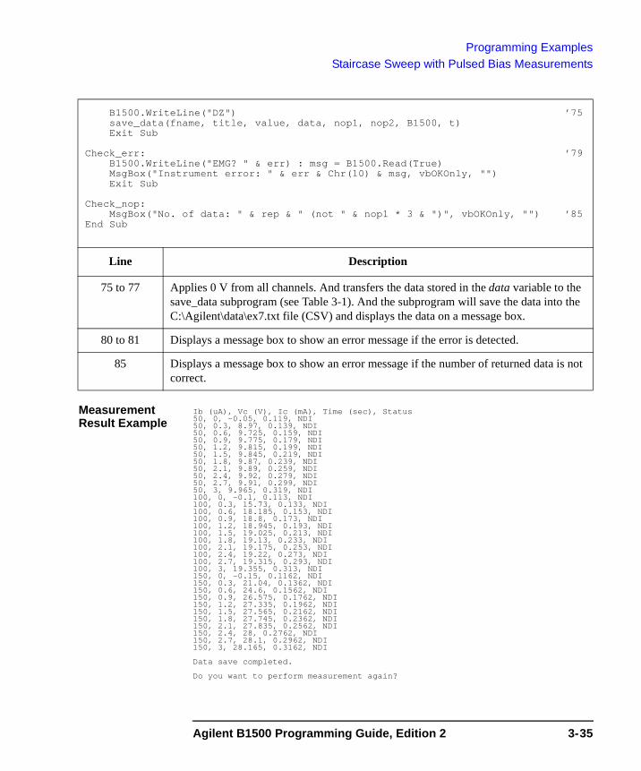
Programming ExamplesStaircase Sweep with Pulsed Bias Measurements
Measurement Result Example
Ib (uA), Vc (V), Ic (mA), Time (sec), Status50, 0, -0.05, 0.119, NDI50, 0.3, 8.97, 0.139, NDI50, 0.6, 9.725, 0.159, NDI50, 0.9, 9.775, 0.179, NDI50, 1.2, 9.815, 0.199, NDI50, 1.5, 9.845, 0.219, NDI50, 1.8, 9.87, 0.239, NDI50, 2.1, 9.89, 0.259, NDI50, 2.4, 9.92, 0.279, NDI50, 2.7, 9.91, 0.299, NDI50, 3, 9.965, 0.319, NDI100, 0, -0.1, 0.113, NDI100, 0.3, 15.73, 0.133, NDI100, 0.6, 18.185, 0.153, NDI100, 0.9, 18.8, 0.173, NDI100, 1.2, 18.945, 0.193, NDI100, 1.5, 19.025, 0.213, NDI100, 1.8, 19.13, 0.233, NDI100, 2.1, 19.175, 0.253, NDI100, 2.4, 19.22, 0.273, NDI100, 2.7, 19.315, 0.293, NDI100, 3, 19.355, 0.313, NDI150, 0, -0.15, 0.1162, NDI150, 0.3, 21.04, 0.1362, NDI150, 0.6, 24.6, 0.1562, NDI150, 0.9, 26.575, 0.1762, NDI150, 1.2, 27.335, 0.1962, NDI150, 1.5, 27.565, 0.2162, NDI150, 1.8, 27.745, 0.2362, NDI150, 2.1, 27.835, 0.2562, NDI150, 2.4, 28, 0.2762, NDI150, 2.7, 28.1, 0.2962, NDI150, 3, 28.165, 0.3162, NDI
Data save completed.
Do you want to perform measurement again?
B1500.WriteLine("DZ") ’75save_data(fname, title, value, data, nop1, nop2, B1500, t)Exit Sub
Check_err: ’79B1500.WriteLine("EMG? " & err) : msg = B1500.Read(True)MsgBox("Instrument error: " & err & Chr(10) & msg, vbOKOnly, "")Exit Sub
Check_nop:MsgBox("No. of data: " & rep & " (not " & nop1 * 3 & ")", vbOKOnly, "") ’85
End Sub
Line Description
75 to 77 Applies 0 V from all channels. And transfers the data stored in the data variable to the save_data subprogram (see Table 3-1). And the subprogram will save the data into the C:\Agilent\data\ex7.txt file (CSV) and displays the data on a message box.
80 to 81 Displays a message box to show an error message if the error is detected.
85 Displays a message box to show an error message if the number of returned data is not correct.
Agilent B1500 Programming Guide, Edition 2 3-35
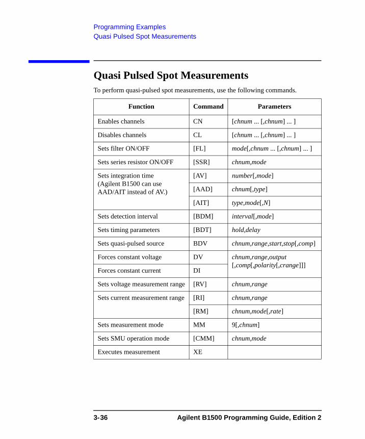
Programming ExamplesQuasi Pulsed Spot Measurements
Quasi Pulsed Spot MeasurementsTo perform quasi-pulsed spot measurements, use the following commands.
Function Command Parameters
Enables channels CN [chnum ... [,chnum] ... ]
Disables channels CL [chnum ... [,chnum] ... ]
Sets filter ON/OFF [FL] mode[,chnum ... [,chnum] ... ]
Sets series resistor ON/OFF [SSR] chnum,mode
Sets integration time (Agilent B1500 can use AAD/AIT instead of AV.)
[AV] number[,mode]
[AAD] chnum[,type]
[AIT] type,mode[,N]
Sets detection interval [BDM] interval[,mode]
Sets timing parameters [BDT] hold,delay
Sets quasi-pulsed source BDV chnum,range,start,stop[,comp]
Forces constant voltage DV chnum,range,output [,comp[,polarity[,crange]]]
Forces constant current DI
Sets voltage measurement range [RV] chnum,range
Sets current measurement range [RI] chnum,range
[RM] chnum,mode[,rate]
Sets measurement mode MM 9[,chnum]
Sets SMU operation mode [CMM] chnum,mode
Executes measurement XE
3-36 Agilent B1500 Programming Guide, Edition 2

Programming ExamplesQuasi Pulsed Spot Measurements
A program example of a spot measurement is shown below. This measures the breakdown voltage of bipolar transistor.
Table 3-10 Quasi Pulsed Spot Measurement Example
Sub perform_meas(ByVal B1500 As DirectIO, ByVal t() As Integer) ’1Dim i As Integer = 0Dim j As Integer = 0Dim nop1 As Integer = 1Dim nop2 As Integer = 1Dim data(nop2 - 1, nop1 - 1) As StringDim value As String = "BVceo (V), Status"Dim fname As String = "C:\Agilent\data\ex8.txt"Dim title As String = "Measurement Result"Dim msg As String = "No error."Dim err As String = "0"
Dim vc1 As Double = 0 ’13Dim vc2 As Double = 100Dim iccomp As Double = 0.005Dim hold As Double = 0Dim delay As Double = 0Dim interval As Double = 0Dim mmode As Double = 0Dim mrng As Integer = 0
B1500.WriteLine("FMT 1") ’22B1500.WriteLine("CL " & t(1) & "," & t(3))B1500.WriteLine("MM 9," & t(2))B1500.WriteLine("BDT " & hold & "," & delay)B1500.WriteLine("BDM " & interval & "," & mmode)B1500.WriteLine("BDV " & t(2) & "," & mrng & "," & vc1 & "," & vc2 & "," &
iccomp)B1500.WriteLine("DV " & t(0) & ",0,0,0.1") ’out= 0 V, comp= 0.1 A ’28B1500.WriteLine("XE")B1500.WriteLine("ERR? 1") : err = B1500.Read(True)If err <> 0 Then B1500.WriteLine("DZ") : GoTo Check_err
Line Description
2 to 11 Declares variables used through the project. And sets the proper values.
13 to 20 Declares variables, and sets the value.
22 to 23 Sets the data output format. And disables SMUs assigned to t(1) and t(3) that are not needed.
24 to 27 Sets the measurement mode, measurement timing parameters, measurement conditions, and source output conditions.
28 to 31 Applies voltage to device, and performs the quasi pulsed spot measurement. And checks if an error occurred. If an error is detected, forces 0 V and goes to Check_err.
Agilent B1500 Programming Guide, Edition 2 3-37
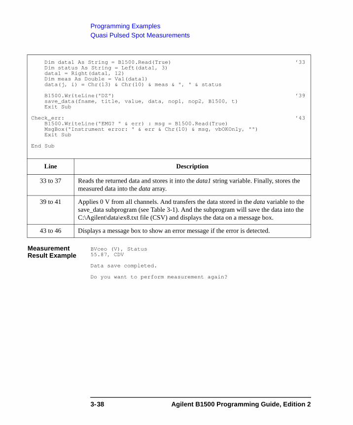
Programming ExamplesQuasi Pulsed Spot Measurements
Measurement Result Example
BVceo (V), Status55.87, CDV
Data save completed.
Do you want to perform measurement again?
Dim data1 As String = B1500.Read(True) ’33Dim status As String = Left(data1, 3)data1 = Right(data1, 12)Dim meas As Double = Val(data1)data(j, i) = Chr(13) & Chr(10) & meas & ", " & status
B1500.WriteLine("DZ") ’39save_data(fname, title, value, data, nop1, nop2, B1500, t)Exit Sub
Check_err: ’43B1500.WriteLine("EMG? " & err) : msg = B1500.Read(True)MsgBox("Instrument error: " & err & Chr(10) & msg, vbOKOnly, "")Exit Sub
End Sub
Line Description
33 to 37 Reads the returned data and stores it into the data1 string variable. Finally, stores the measured data into the data array.
39 to 41 Applies 0 V from all channels. And transfers the data stored in the data variable to the save_data subprogram (see Table 3-1). And the subprogram will save the data into the C:\Agilent\data\ex8.txt file (CSV) and displays the data on a message box.
43 to 46 Displays a message box to show an error message if the error is detected.
3-38 Agilent B1500 Programming Guide, Edition 2

Programming ExamplesLinear Search Measurements
Linear Search MeasurementsTo perform linear search measurements, use the following commands.
The LSV and LSI commands clear the previous source settings.
Send the LSI command before sending the LSSI command.
Send the LSV command before sending the LSSV command.
The LSI/LSSV commands or LSV/LSSI commands cannot be used together.
Function Command Parameters
Enables channels CN [chnum ... [,chnum] ... ]
Disables channels CL [chnum ... [,chnum] ... ]
Sets filter ON/OFF [FL] mode[,chnum ... [,chnum] ... ]
Sets series resistor ON/OFF [SSR] chnum,mode
Sets integration time (Agilent B1500 can use AAD/AIT instead of AV.)
[AV] number[,mode]
[AAD] chnum[,type]
[AIT] type,mode[,N]
Sets measurement mode MM 14
Selects output data [LSVM] output_data
Sets timing parameters [LSTM] hold,delay
Sets auto abort function [LSM] abort[,post]
Sets current search or voltage search condition
LGI or LGV
chnum,mode,range,target
Sets voltage source or current source
LSV or LSI
chnum,range,start,stop,step [,comp]
Sets synchronous voltage source or current source
[LSSV] or [LSSI]
chnum,polarity,offset[,comp]
Forces constant voltage DV chnum,range,output [,comp[,polarity[,crange]]]Forces constant current DI
Executes measurement XE
Agilent B1500 Programming Guide, Edition 2 3-39
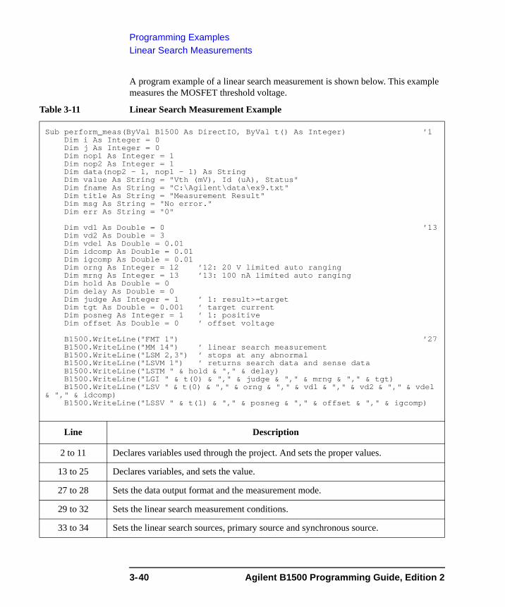
Programming ExamplesLinear Search Measurements
A program example of a linear search measurement is shown below. This example measures the MOSFET threshold voltage.
Table 3-11 Linear Search Measurement Example
Sub perform_meas(ByVal B1500 As DirectIO, ByVal t() As Integer) ’1Dim i As Integer = 0Dim j As Integer = 0Dim nop1 As Integer = 1Dim nop2 As Integer = 1Dim data(nop2 - 1, nop1 - 1) As StringDim value As String = "Vth (mV), Id (uA), Status"Dim fname As String = "C:\Agilent\data\ex9.txt"Dim title As String = "Measurement Result"Dim msg As String = "No error."Dim err As String = "0"
Dim vd1 As Double = 0 ’13Dim vd2 As Double = 3Dim vdel As Double = 0.01Dim idcomp As Double = 0.01Dim igcomp As Double = 0.01Dim orng As Integer = 12 ’12: 20 V limited auto rangingDim mrng As Integer = 13 ’13: 100 nA limited auto rangingDim hold As Double = 0Dim delay As Double = 0Dim judge As Integer = 1 ’ 1: result>=targetDim tgt As Double = 0.001 ’ target currentDim posneg As Integer = 1 ’ 1: positiveDim offset As Double = 0 ’ offset voltage
B1500.WriteLine("FMT 1") ’27B1500.WriteLine("MM 14") ’ linear search measurementB1500.WriteLine("LSM 2,3") ’ stops at any abnormalB1500.WriteLine("LSVM 1") ’ returns search data and sense dataB1500.WriteLine("LSTM " & hold & "," & delay)B1500.WriteLine("LGI " & t(0) & "," & judge & "," & mrng & "," & tgt)B1500.WriteLine("LSV " & t(0) & "," & orng & "," & vd1 & "," & vd2 & "," & vdel
& "," & idcomp)B1500.WriteLine("LSSV " & t(1) & "," & posneg & "," & offset & "," & igcomp)
Line Description
2 to 11 Declares variables used through the project. And sets the proper values.
13 to 25 Declares variables, and sets the value.
27 to 28 Sets the data output format and the measurement mode.
29 to 32 Sets the linear search measurement conditions.
33 to 34 Sets the linear search sources, primary source and synchronous source.
3-40 Agilent B1500 Programming Guide, Edition 2
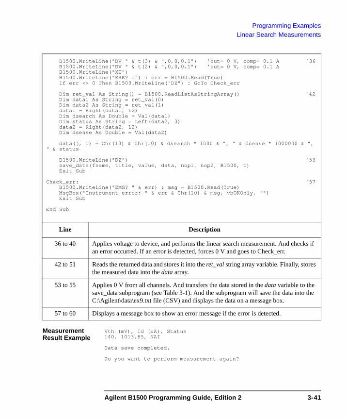
Programming ExamplesLinear Search Measurements
Measurement Result Example
Vth (mV), Id (uA), Status140, 1013.85, NAI
Data save completed.
Do you want to perform measurement again?
B1500.WriteLine("DV " & t(3) & ",0,0,0.1") ’out= 0 V, comp= 0.1 A ’36B1500.WriteLine("DV " & t(2) & ",0,0,0.1") ’out= 0 V, comp= 0.1 AB1500.WriteLine("XE")B1500.WriteLine("ERR? 1") : err = B1500.Read(True)If err <> 0 Then B1500.WriteLine("DZ") : GoTo Check_err
Dim ret_val As String() = B1500.ReadListAsStringArray() ’42Dim data1 As String = ret_val(0)Dim data2 As String = ret_val(1)data1 = Right(data1, 12)Dim dsearch As Double = Val(data1)Dim status As String = Left(data2, 3)data2 = Right(data2, 12)Dim dsense As Double = Val(data2)
data(j, i) = Chr(13) & Chr(10) & dsearch * 1000 & ", " & dsense * 1000000 & ", " & status
B1500.WriteLine("DZ") ’53save_data(fname, title, value, data, nop1, nop2, B1500, t)Exit Sub
Check_err: ’57B1500.WriteLine("EMG? " & err) : msg = B1500.Read(True)MsgBox("Instrument error: " & err & Chr(10) & msg, vbOKOnly, "")Exit Sub
End Sub
Line Description
36 to 40 Applies voltage to device, and performs the linear search measurement. And checks if an error occurred. If an error is detected, forces 0 V and goes to Check_err.
42 to 51 Reads the returned data and stores it into the ret_val string array variable. Finally, stores the measured data into the data array.
53 to 55 Applies 0 V from all channels. And transfers the data stored in the data variable to the save_data subprogram (see Table 3-1). And the subprogram will save the data into the C:\Agilent\data\ex9.txt file (CSV) and displays the data on a message box.
57 to 60 Displays a message box to show an error message if the error is detected.
Agilent B1500 Programming Guide, Edition 2 3-41
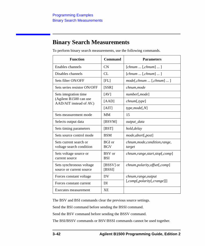
Programming ExamplesBinary Search Measurements
Binary Search MeasurementsTo perform binary search measurements, use the following commands.
The BSV and BSI commands clear the previous source settings.
Send the BSI command before sending the BSSI command.
Send the BSV command before sending the BSSV command.
The BSI/BSSV commands or BSV/BSSI commands cannot be used together.
Function Command Parameters
Enables channels CN [chnum ... [,chnum] ... ]
Disables channels CL [chnum ... [,chnum] ... ]
Sets filter ON/OFF [FL] mode[,chnum ... [,chnum] ... ]
Sets series resistor ON/OFF [SSR] chnum,mode
Sets integration time (Agilent B1500 can use AAD/AIT instead of AV.)
[AV] number[,mode]
[AAD] chnum[,type]
[AIT] type,mode[,N]
Sets measurement mode MM 15
Selects output data [BSVM] output_data
Sets timing parameters [BST] hold,delay
Sets source control mode BSM mode,abort[,post]
Sets current search or voltage search condition
BGI or BGV
chnum,mode,condition,range, target
Sets voltage source or current source
BSV or BSI
chnum,range,start,stop[,comp]
Sets synchronous voltage source or current source
[BSSV] or [BSSI]
chnum,polarity,offset[,comp]
Forces constant voltage DV chnum,range,output [,comp[,polarity[,crange]]]Forces constant current DI
Executes measurement XE
3-42 Agilent B1500 Programming Guide, Edition 2
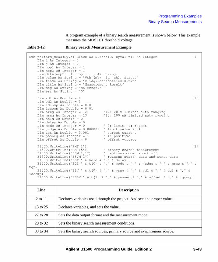
Programming ExamplesBinary Search Measurements
A program example of a binary search measurement is shown below. This example measures the MOSFET threshold voltage.
Table 3-12 Binary Search Measurement Example
Sub perform_meas(ByVal B1500 As DirectIO, ByVal t() As Integer) ’1Dim i As Integer = 0Dim j As Integer = 0Dim nop1 As Integer = 1Dim nop2 As Integer = 1Dim data(nop2 - 1, nop1 - 1) As StringDim value As String = "Vth (mV), Id (uA), Status"Dim fname As String = "C:\Agilent\data\ex10.txt"Dim title As String = "Measurement Result"Dim msg As String = "No error."Dim err As String = "0"
Dim vd1 As Double = 0 ’13Dim vd2 As Double = 3Dim idcomp As Double = 0.01Dim igcomp As Double = 0.01Dim orng As Integer = 12 ’12: 20 V limited auto rangingDim mrng As Integer = 13 ’13: 100 nA limited auto rangingDim hold As Double = 0Dim delay As Double = 0Dim mode As Integer = 0 ’ 0: limit, 1: repeatDim judge As Double = 0.000001 ’ limit value in ADim tgt As Double = 0.001 ’ target currentDim posneg As Integer = 1 ’ 1: positiveDim offset As Double = 0 ’ offset voltage
B1500.WriteLine("FMT 1") ’27B1500.WriteLine("MM 15") ’ binary search measurementB1500.WriteLine("BSM 1,1") ’ cautious mode, abort offB1500.WriteLine("BSVM 1") ’ returns search data and sense dataB1500.WriteLine("BST " & hold & "," & delay)B1500.WriteLine("BGI " & t(0) & "," & mode & "," & judge & "," & mrng & "," &
tgt)B1500.WriteLine("BSV " & t(0) & "," & orng & "," & vd1 & "," & vd2 & "," &
idcomp)B1500.WriteLine("BSSV " & t(1) & "," & posneg & "," & offset & "," & igcomp)
Line Description
2 to 11 Declares variables used through the project. And sets the proper values.
13 to 25 Declares variables, and sets the value.
27 to 28 Sets the data output format and the measurement mode.
29 to 32 Sets the binary search measurement conditions.
33 to 34 Sets the binary search sources, primary source and synchronous source.
Agilent B1500 Programming Guide, Edition 2 3-43
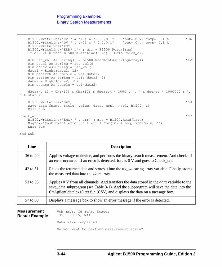
Programming ExamplesBinary Search Measurements
Measurement Result Example
Vth (mV), Id (uA), Status139, 999.15, NAI
Data save completed.
Do you want to perform measurement again?
B1500.WriteLine("DV " & t(3) & ",0,0,0.1") ’out= 0 V, comp= 0.1 A ’36B1500.WriteLine("DV " & t(2) & ",0,0,0.1") ’out= 0 V, comp= 0.1 AB1500.WriteLine("XE")B1500.WriteLine("ERR? 1") : err = B1500.Read(True)If err <> 0 Then B1500.WriteLine("DZ") : GoTo Check_err
Dim ret_val As String() = B1500.ReadListAsStringArray() ’42Dim data1 As String = ret_val(0)Dim data2 As String = ret_val(1)data1 = Right(data1, 12)Dim dsearch As Double = Val(data1)Dim status As String = Left(data2, 3)data2 = Right(data2, 12)Dim dsense As Double = Val(data2)
data(j, i) = Chr(13) & Chr(10) & dsearch * 1000 & ", " & dsense * 1000000 & ", " & status
B1500.WriteLine("DZ") ’53save_data(fname, title, value, data, nop1, nop2, B1500, t)Exit Sub
Check_err: ’57B1500.WriteLine("EMG? " & err) : msg = B1500.Read(True)MsgBox("Instrument error: " & err & Chr(10) & msg, vbOKOnly, "")Exit Sub
End Sub
Line Description
36 to 40 Applies voltage to device, and performs the binary search measurement. And checks if an error occurred. If an error is detected, forces 0 V and goes to Check_err.
42 to 51 Reads the returned data and stores it into the ret_val string array variable. Finally, stores the measured data into the data array.
53 to 55 Applies 0 V from all channels. And transfers the data stored in the data variable to the save_data subprogram (see Table 3-1). And the subprogram will save the data into the C:\Agilent\data\ex10.txt file (CSV) and displays the data on a message box.
57 to 60 Displays a message box to show an error message if the error is detected.
3-44 Agilent B1500 Programming Guide, Edition 2
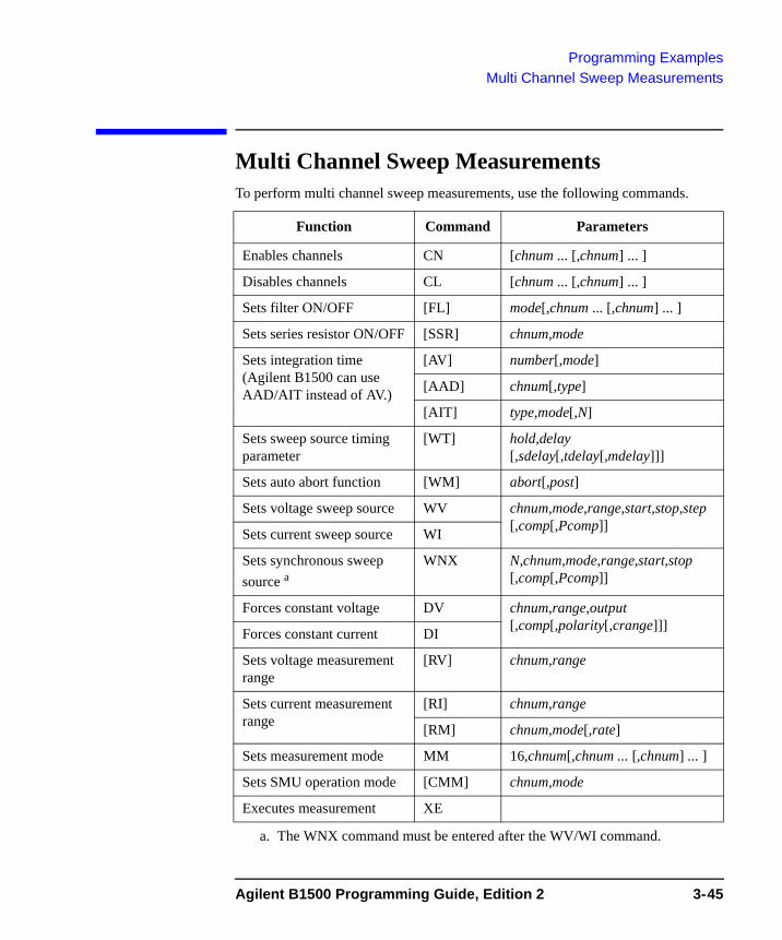
Programming ExamplesMulti Channel Sweep Measurements
Multi Channel Sweep MeasurementsTo perform multi channel sweep measurements, use the following commands.
Function Command Parameters
Enables channels CN [chnum ... [,chnum] ... ]
Disables channels CL [chnum ... [,chnum] ... ]
Sets filter ON/OFF [FL] mode[,chnum ... [,chnum] ... ]
Sets series resistor ON/OFF [SSR] chnum,mode
Sets integration time (Agilent B1500 can use AAD/AIT instead of AV.)
[AV] number[,mode]
[AAD] chnum[,type]
[AIT] type,mode[,N]
Sets sweep source timing parameter
[WT] hold,delay [,sdelay[,tdelay[,mdelay]]]
Sets auto abort function [WM] abort[,post]
Sets voltage sweep source WV chnum,mode,range,start,stop,step [,comp[,Pcomp]]Sets current sweep source WI
Sets synchronous sweep source a
a. The WNX command must be entered after the WV/WI command.
WNX N,chnum,mode,range,start,stop [,comp[,Pcomp]]
Forces constant voltage DV chnum,range,output [,comp[,polarity[,crange]]]Forces constant current DI
Sets voltage measurement range
[RV] chnum,range
Sets current measurement range
[RI] chnum,range
[RM] chnum,mode[,rate]
Sets measurement mode MM 16,chnum[,chnum ... [,chnum] ... ]
Sets SMU operation mode [CMM] chnum,mode
Executes measurement XE
Agilent B1500 Programming Guide, Edition 2 3-45
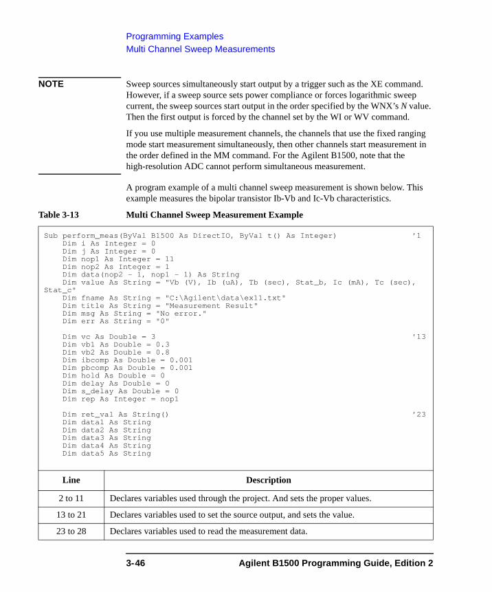
Programming ExamplesMulti Channel Sweep Measurements
NOTE Sweep sources simultaneously start output by a trigger such as the XE command. However, if a sweep source sets power compliance or forces logarithmic sweep current, the sweep sources start output in the order specified by the WNX’s N value. Then the first output is forced by the channel set by the WI or WV command.
If you use multiple measurement channels, the channels that use the fixed ranging mode start measurement simultaneously, then other channels start measurement in the order defined in the MM command. For the Agilent B1500, note that the high-resolution ADC cannot perform simultaneous measurement.
A program example of a multi channel sweep measurement is shown below. This example measures the bipolar transistor Ib-Vb and Ic-Vb characteristics.
Table 3-13 Multi Channel Sweep Measurement Example
Sub perform_meas(ByVal B1500 As DirectIO, ByVal t() As Integer) ’1Dim i As Integer = 0Dim j As Integer = 0Dim nop1 As Integer = 11Dim nop2 As Integer = 1Dim data(nop2 - 1, nop1 - 1) As StringDim value As String = "Vb (V), Ib (uA), Tb (sec), Stat_b, Ic (mA), Tc (sec),
Stat_c"Dim fname As String = "C:\Agilent\data\ex11.txt"Dim title As String = "Measurement Result"Dim msg As String = "No error."Dim err As String = "0"
Dim vc As Double = 3 ’13Dim vb1 As Double = 0.3Dim vb2 As Double = 0.8Dim ibcomp As Double = 0.001Dim pbcomp As Double = 0.001Dim hold As Double = 0Dim delay As Double = 0Dim s_delay As Double = 0Dim rep As Integer = nop1
Dim ret_val As String() ’23Dim data1 As StringDim data2 As StringDim data3 As StringDim data4 As StringDim data5 As String
Line Description
2 to 11 Declares variables used through the project. And sets the proper values.
13 to 21 Declares variables used to set the source output, and sets the value.
23 to 28 Declares variables used to read the measurement data.
3-46 Agilent B1500 Programming Guide, Edition 2
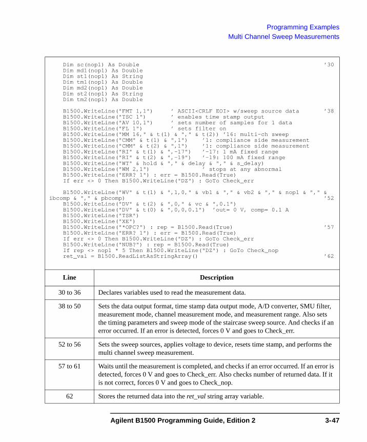
Programming ExamplesMulti Channel Sweep Measurements
Dim sc(nop1) As Double ’30Dim md1(nop1) As DoubleDim st1(nop1) As StringDim tm1(nop1) As DoubleDim md2(nop1) As DoubleDim st2(nop1) As StringDim tm2(nop1) As Double
B1500.WriteLine("FMT 1,1") ’ ASCII<CRLF EOI> w/sweep source data ’38B1500.WriteLine("TSC 1") ’ enables time stamp outputB1500.WriteLine("AV 10,1") ’ sets number of samples for 1 dataB1500.WriteLine("FL 1") ’ sets filter onB1500.WriteLine("MM 16," & t(1) & "," & t(2)) ’16: multi-ch sweepB1500.WriteLine("CMM" & t(1) & ",1") ’1: compliance side measurementB1500.WriteLine("CMM" & t(2) & ",1") ’1: compliance side measurementB1500.WriteLine("RI" & t(1) & ",-17") ’-17: 1 mA fixed rangeB1500.WriteLine("RI" & t(2) & ",-19") ’-19: 100 mA fixed rangeB1500.WriteLine("WT" & hold & "," & delay & "," & s_delay)B1500.WriteLine("WM 2,1") ’ stops at any abnormalB1500.WriteLine("ERR? 1") : err = B1500.Read(True)If err <> 0 Then B1500.WriteLine("DZ") : GoTo Check_err
B1500.WriteLine("WV" & t(1) & ",1,0," & vb1 & "," & vb2 & "," & nop1 & "," & ibcomp & "," & pbcomp) ’52
B1500.WriteLine("DV" & t(2) & ",0," & vc & ",0.1")B1500.WriteLine("DV" & t(0) & ",0,0,0.1") ’out= 0 V, comp= 0.1 AB1500.WriteLine("TSR")B1500.WriteLine("XE")B1500.WriteLine("*OPC?") : rep = B1500.Read(True) ’57B1500.WriteLine("ERR? 1") : err = B1500.Read(True)If err <> 0 Then B1500.WriteLine("DZ") : GoTo Check_errB1500.WriteLine("NUB?") : rep = B1500.Read(True)If rep <> nop1 * 5 Then B1500.WriteLine("DZ") : GoTo Check_nopret_val = B1500.ReadListAsStringArray() ’62
Line Description
30 to 36 Declares variables used to read the measurement data.
38 to 50 Sets the data output format, time stamp data output mode, A/D converter, SMU filter, measurement mode, channel measurement mode, and measurement range. Also sets the timing parameters and sweep mode of the staircase sweep source. And checks if an error occurred. If an error is detected, forces 0 V and goes to Check_err.
52 to 56 Sets the sweep sources, applies voltage to device, resets time stamp, and performs the multi channel sweep measurement.
57 to 61 Waits until the measurement is completed, and checks if an error occurred. If an error is detected, forces 0 V and goes to Check_err. Also checks number of returned data. If it is not correct, forces 0 V and goes to Check_nop.
62 Stores the returned data into the ret_val string array variable.
Agilent B1500 Programming Guide, Edition 2 3-47
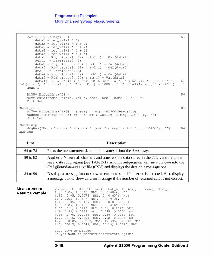
Programming ExamplesMulti Channel Sweep Measurements
Measurement Result Example
Vb (V), Ib (uA), Tb (sec), Stat_b, Ic (mA), Tc (sec), Stat_c0.3, 0.05, 0.0046, NBI, 0, 0.0046, NDI0.35, 0.05, 0.0076, NBI, 0, 0.0076, NDI0.4, 0.05, 0.0106, NBI, 0, 0.0106, NDI0.45, 0.05, 0.0135, NBI, 0, 0.0135, NDI0.5, 0.05, 0.0165, NBI, 0, 0.0165, NDI0.55, 0.1, 0.0195, NBI, 0.01, 0.0195, NDI0.6, 0.45, 0.0224, NBI, 0.085, 0.0224, NDI0.65, 2.95, 0.0254, NBI, 0.58, 0.0254, NDI0.7, 18.45, 0.0284, NBI, 3.72, 0.0284, NDI0.75, 90.85, 0.0313, NBI, 17.635, 0.0313, NDI0.8, 290.5, 0.0343, NBI, 50.15, 0.0343, NDI
Data save completed.Do you want to perform measurement again?
For i = 0 To nop1 - 1 ’64data1 = ret_val(i * 5)data2 = ret_val(i * 5 + 1)data3 = ret_val(i * 5 + 2)data4 = ret_val(i * 5 + 3)data5 = ret_val(i * 5 + 4)data1 = Right(data1, 12) : tm1(i) = Val(data1)st1(i) = Left(data2, 3)data2 = Right(data2, 12) : md1(i) = Val(data2)data3 = Right(data1, 12) : tm2(i) = Val(data3)st2(i) = Left(data4, 3)data4 = Right(data4, 12) : md2(i) = Val(data4)data5 = Right(data5, 12) : sc(i) = Val(data5)data(j, i) = Chr(13) & Chr(10) & sc(i) & ", " & md1(i) * 1000000 & ", " &
tm1(i) & ", " & st1(i) & ", " & md2(i) * 1000 & ", " & tm2(i) & ", " & st2(i)Next i
B1500.WriteLine("DZ") ’80save_data(fname, title, value, data, nop1, nop2, B1500, t)Exit Sub
Check_err: ’84B1500.WriteLine("EMG? " & err) : msg = B1500.Read(True)MsgBox("Instrument error: " & err & Chr(10) & msg, vbOKOnly, "")Exit Sub
Check_nop:MsgBox("No. of data: " & rep & " (not " & nop1 * 3 & ")", vbOKOnly, "") ’90
End Sub
Line Description
64 to 78 Picks the measurement data out and stores it into the data array.
80 to 82 Applies 0 V from all channels and transfers the data stored in the data variable to the save_data subprogram (see Table 3-1). And the subprogram will save the data into the C:\Agilent\data\ex11.txt file (CSV) and displays the data on a message box.
84 to 90 Displays a message box to show an error message if the error is detected. Also displays a message box to show an error message if the number of returned data is not correct.
3-48 Agilent B1500 Programming Guide, Edition 2
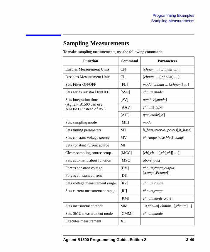
Programming ExamplesSampling Measurements
Sampling Measurements To make sampling measurements, use the following commands.
Function Command Parameters
Enables Measurement Units CN [chnum ... [,chnum] ... ]
Disables Measurement Units CL [chnum ... [,chnum] ... ]
Sets Filter ON/OFF [FL] mode[,chnum ... [,chnum] ... ]
Sets series resistor ON/OFF [SSR] chnum,mode
Sets integration time (Agilent B1500 can use AAD/AIT instead of AV.)
[AV] number[,mode]
[AAD] chnum[,type]
[AIT] type,mode[,N]
Sets sampling mode [ML] mode
Sets timing parameters MT h_bias,interval,points[,h_base]
Sets constant voltage source MV ch,range,base,bias[,comp]
Sets constant current source MI
Clears sampling source setup [MCC] [ch[,ch ... [,ch[,ch]] ... ]]
Sets automatic abort function [MSC] abort[,post]
Forces constant voltage [DV] chnum,range,output[,comp[,Pcomp]]
Forces constant current [DI]
Sets voltage measurement range [RV] chnum,range
Sets current measurement range [RI] chnum,range
[RM] chnum,mode[,rate]
Sets measurement mode MM 10,chnum[,chnum ..[,chnum] ..]
Sets SMU measurement mode [CMM] chnum,mode
Executes measurement XE
Agilent B1500 Programming Guide, Edition 2 3-49

Programming ExamplesSampling Measurements
Table 3-14 explains example subprogram that performs linear sampling measurement. This example measures current that flows to resistors R1 and R2, and then calculates the resistance.
Table 3-14 Sampling Measurement Example
Sub perform_meas(ByVal B1500 As DirectIO, ByVal t() As Integer) ’1Dim i As Integer = 0Dim j As Integer = 0Dim nop1 As Integer = 30Dim nop2 As Integer = 1Dim data(nop2, nop1) As StringDim value As String = "Index, I1 (mA), R1 (ohm), St1, I2 (mA), R2 (ohm), St2"Dim fname As String = "C:\Agilent\data\ex12.txt"Dim title As String = "Sampling Measurement Result"Dim msg As String = "No error."Dim err As Integer = 0
Dim base As Double = 0 ’13Dim bias As Double = 0.1Dim icomp As Double = 0.1Dim vlout As Double = 0Dim ilcomp As Double = 0.1Dim base_h As Double = 0Dim bias_h As Double = 0.1Dim interval As Double = 0.05Dim mch() As Integer = {t(1), t(2), 0}Dim range() As Double = {0, 0}Dim rep As Integer = nop1 ’23Dim ret_val As String()Dim data1 As StringDim data2 As StringDim data3 As StringDim id(nop1) As DoubleDim d1(nop1) As DoubleDim d2(nop1) As DoubleDim r1(nop1) As DoubleDim r2(nop1) As DoubleDim s1(nop1) As StringDim s2(nop1) As String ’34
Line Description
2 to 11 Declares variables used through the project. And sets the proper values.
13 to 22 Declares variables used to set the source output, and sets the value.
23 to 34 Declares variables used to read the measurement data.
3-50 Agilent B1500 Programming Guide, Edition 2
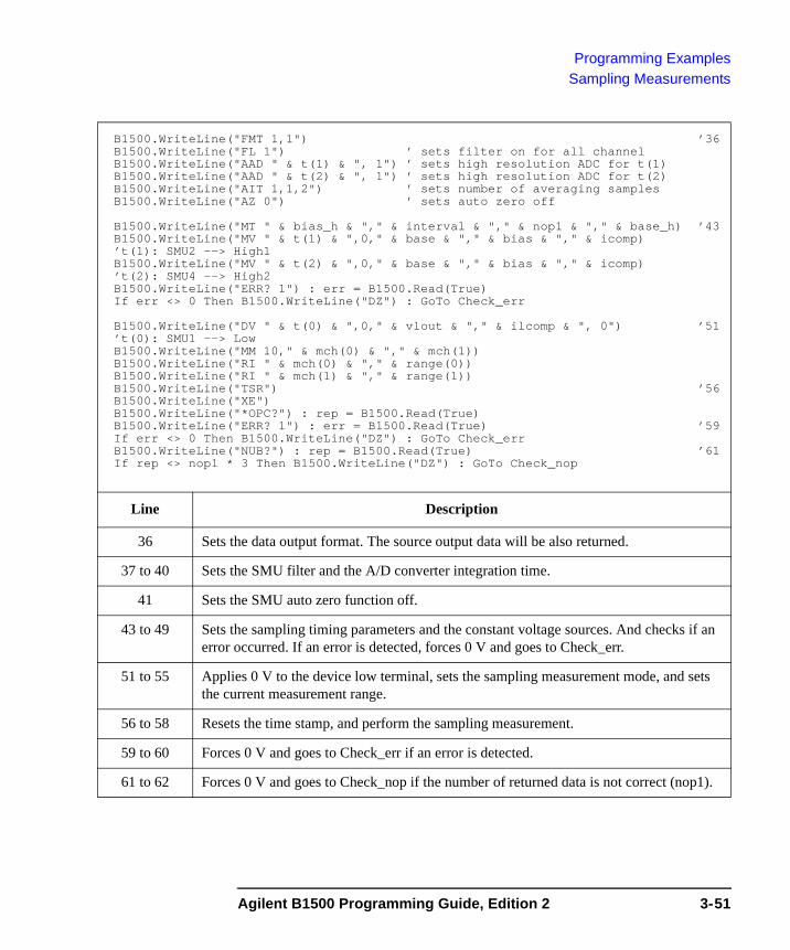
Programming ExamplesSampling Measurements
B1500.WriteLine("FMT 1,1") ’36B1500.WriteLine("FL 1") ’ sets filter on for all channelB1500.WriteLine("AAD " & t(1) & ", 1") ’ sets high resolution ADC for t(1)B1500.WriteLine("AAD " & t(2) & ", 1") ’ sets high resolution ADC for t(2)B1500.WriteLine("AIT 1,1,2") ’ sets number of averaging samplesB1500.WriteLine("AZ 0") ’ sets auto zero off
B1500.WriteLine("MT " & bias_h & "," & interval & "," & nop1 & "," & base_h) ’43B1500.WriteLine("MV " & t(1) & ",0," & base & "," & bias & "," & icomp)’t(1): SMU2 --> High1B1500.WriteLine("MV " & t(2) & ",0," & base & "," & bias & "," & icomp)’t(2): SMU4 --> High2B1500.WriteLine("ERR? 1") : err = B1500.Read(True)If err <> 0 Then B1500.WriteLine("DZ") : GoTo Check_err
B1500.WriteLine("DV " & t(0) & ",0," & vlout & "," & ilcomp & ", 0") ’51’t(0): SMU1 --> LowB1500.WriteLine("MM 10," & mch(0) & "," & mch(1))B1500.WriteLine("RI " & mch(0) & "," & range(0))B1500.WriteLine("RI " & mch(1) & "," & range(1))B1500.WriteLine("TSR") ’56B1500.WriteLine("XE")B1500.WriteLine("*OPC?") : rep = B1500.Read(True)B1500.WriteLine("ERR? 1") : err = B1500.Read(True) ’59If err <> 0 Then B1500.WriteLine("DZ") : GoTo Check_errB1500.WriteLine("NUB?") : rep = B1500.Read(True) ’61If rep <> nop1 * 3 Then B1500.WriteLine("DZ") : GoTo Check_nop
Line Description
36 Sets the data output format. The source output data will be also returned.
37 to 40 Sets the SMU filter and the A/D converter integration time.
41 Sets the SMU auto zero function off.
43 to 49 Sets the sampling timing parameters and the constant voltage sources. And checks if an error occurred. If an error is detected, forces 0 V and goes to Check_err.
51 to 55 Applies 0 V to the device low terminal, sets the sampling measurement mode, and sets the current measurement range.
56 to 58 Resets the time stamp, and perform the sampling measurement.
59 to 60 Forces 0 V and goes to Check_err if an error is detected.
61 to 62 Forces 0 V and goes to Check_nop if the number of returned data is not correct (nop1).
Agilent B1500 Programming Guide, Edition 2 3-51
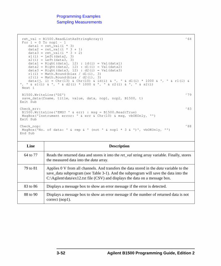
Programming ExamplesSampling Measurements
ret_val = B1500.ReadListAsStringArray() ’64For i = 0 To nop1 - 1
data1 = ret_val(i * 3)data2 = ret_val(i * 3 + 1)data3 = ret_val(i * 3 + 2)s1(i) = Left(data2, 3)s2(i) = Left(data3, 3)data1 = Right(data1, 12) : id(i) = Val(data1)data2 = Right(data2, 12) : d1(i) = Val(data2)data3 = Right(data3, 12) : d2(i) = Val(data3)r1(i) = Math.Round(bias / d1(i), 3)r2(i) = Math.Round(bias / d2(i), 3)data(j, i) = Chr(13) & Chr(10) & id(i) & ", " & d1(i) * 1000 & ", " & r1(i) &
", " & s1(i) & ", " & d2(i) * 1000 & ", " & r2(i) & ", " & s2(i)Next i
B1500.WriteLine("DZ") ’79save_data(fname, title, value, data, nop1, nop2, B1500, t)
Exit Sub
Check_err: ’83B1500.WriteLine("EMG? " & err) : msg = B1500.Read(True)MsgBox("Instrument error: " & err & Chr(10) & msg, vbOKOnly, "")
Exit Sub
Check_nop: ’88MsgBox("No. of data: " & rep & " (not " & nop1 * 3 & ")", vbOKOnly, "")
End Sub
Line Description
64 to 77 Reads the returned data and stores it into the ret_val string array variable. Finally, stores the measured data into the data array.
79 to 81 Applies 0 V from all channels. And transfers the data stored in the data variable to the save_data subprogram (see Table 3-1). And the subprogram will save the data into the C:\Agilent\data\ex12.txt file (CSV) and displays the data on a message box.
83 to 86 Displays a message box to show an error message if the error is detected.
88 to 90 Displays a message box to show an error message if the number of returned data is not correct (nop1).
3-52 Agilent B1500 Programming Guide, Edition 2
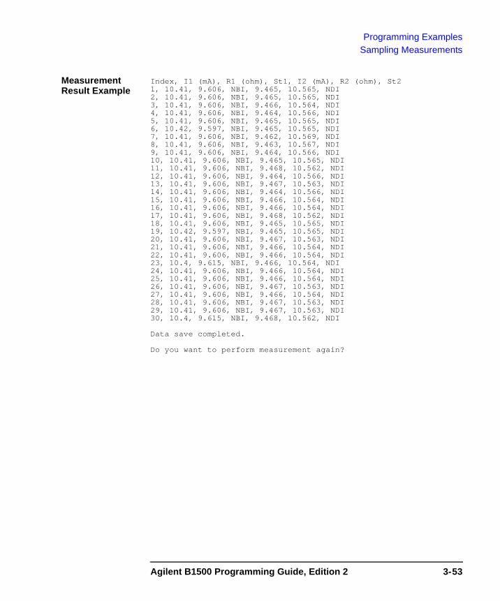
Programming ExamplesSampling Measurements
Measurement Result Example
Index, I1 (mA), R1 (ohm), St1, I2 (mA), R2 (ohm), St21, 10.41, 9.606, NBI, 9.465, 10.565, NDI2, 10.41, 9.606, NBI, 9.465, 10.565, NDI3, 10.41, 9.606, NBI, 9.466, 10.564, NDI4, 10.41, 9.606, NBI, 9.464, 10.566, NDI5, 10.41, 9.606, NBI, 9.465, 10.565, NDI6, 10.42, 9.597, NBI, 9.465, 10.565, NDI7, 10.41, 9.606, NBI, 9.462, 10.569, NDI8, 10.41, 9.606, NBI, 9.463, 10.567, NDI9, 10.41, 9.606, NBI, 9.464, 10.566, NDI10, 10.41, 9.606, NBI, 9.465, 10.565, NDI11, 10.41, 9.606, NBI, 9.468, 10.562, NDI12, 10.41, 9.606, NBI, 9.464, 10.566, NDI13, 10.41, 9.606, NBI, 9.467, 10.563, NDI14, 10.41, 9.606, NBI, 9.464, 10.566, NDI15, 10.41, 9.606, NBI, 9.466, 10.564, NDI16, 10.41, 9.606, NBI, 9.466, 10.564, NDI17, 10.41, 9.606, NBI, 9.468, 10.562, NDI18, 10.41, 9.606, NBI, 9.465, 10.565, NDI19, 10.42, 9.597, NBI, 9.465, 10.565, NDI20, 10.41, 9.606, NBI, 9.467, 10.563, NDI21, 10.41, 9.606, NBI, 9.466, 10.564, NDI22, 10.41, 9.606, NBI, 9.466, 10.564, NDI23, 10.4, 9.615, NBI, 9.466, 10.564, NDI24, 10.41, 9.606, NBI, 9.466, 10.564, NDI25, 10.41, 9.606, NBI, 9.466, 10.564, NDI26, 10.41, 9.606, NBI, 9.467, 10.563, NDI27, 10.41, 9.606, NBI, 9.466, 10.564, NDI28, 10.41, 9.606, NBI, 9.467, 10.563, NDI29, 10.41, 9.606, NBI, 9.467, 10.563, NDI30, 10.4, 9.615, NBI, 9.468, 10.562, NDI
Data save completed.
Do you want to perform measurement again?
Agilent B1500 Programming Guide, Edition 2 3-53
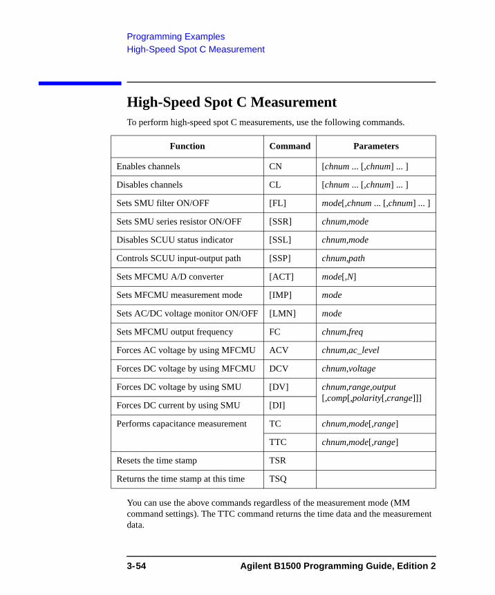
Programming ExamplesHigh-Speed Spot C Measurement
High-Speed Spot C MeasurementTo perform high-speed spot C measurements, use the following commands.
You can use the above commands regardless of the measurement mode (MM command settings). The TTC command returns the time data and the measurement data.
Function Command Parameters
Enables channels CN [chnum ... [,chnum] ... ]
Disables channels CL [chnum ... [,chnum] ... ]
Sets SMU filter ON/OFF [FL] mode[,chnum ... [,chnum] ... ]
Sets SMU series resistor ON/OFF [SSR] chnum,mode
Disables SCUU status indicator [SSL] chnum,mode
Controls SCUU input-output path [SSP] chnum,path
Sets MFCMU A/D converter [ACT] mode[,N]
Sets MFCMU measurement mode [IMP] mode
Sets AC/DC voltage monitor ON/OFF [LMN] mode
Sets MFCMU output frequency FC chnum,freq
Forces AC voltage by using MFCMU ACV chnum,ac_level
Forces DC voltage by using MFCMU DCV chnum,voltage
Forces DC voltage by using SMU [DV] chnum,range,output [,comp[,polarity[,crange]]]
Forces DC current by using SMU [DI]
Performs capacitance measurement TC chnum,mode[,range]
TTC chnum,mode[,range]
Resets the time stamp TSR
Returns the time stamp at this time TSQ
3-54 Agilent B1500 Programming Guide, Edition 2
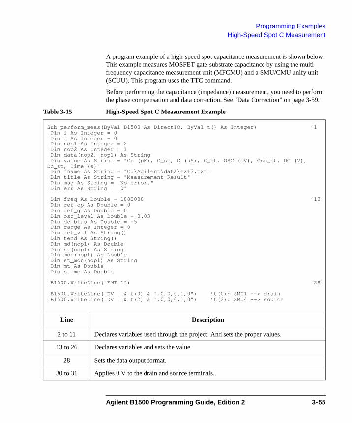
Programming ExamplesHigh-Speed Spot C Measurement
A program example of a high-speed spot capacitance measurement is shown below. This example measures MOSFET gate-substrate capacitance by using the multi frequency capacitance measurement unit (MFCMU) and a SMU/CMU unify unit (SCUU). This program uses the TTC command.
Before performing the capacitance (impedance) measurement, you need to perform the phase compensation and data correction. See “Data Correction” on page 3-59.
Table 3-15 High-Speed Spot C Measurement Example
Sub perform_meas(ByVal B1500 As DirectIO, ByVal t() As Integer) ’1Dim i As Integer = 0Dim j As Integer = 0Dim nop1 As Integer = 2Dim nop2 As Integer = 1Dim data(nop2, nop1) As StringDim value As String = "Cp (pF), C_st, G (uS), G_st, OSC (mV), Osc_st, DC (V),
Dc_st, Time (s)"Dim fname As String = "C:\Agilent\data\ex13.txt"Dim title As String = "Measurement Result"Dim msg As String = "No error."Dim err As String = "0"
Dim freq As Double = 1000000 ’13Dim ref_cp As Double = 0Dim ref_g As Double = 0Dim osc_level As Double = 0.03Dim dc_bias As Double = -5Dim range As Integer = 0Dim ret_val As String()Dim tend As String()Dim md(nop1) As DoubleDim st(nop1) As StringDim mon(nop1) As DoubleDim st_mon(nop1) As StringDim mt As DoubleDim stime As Double
B1500.WriteLine("FMT 1") ’28
B1500.WriteLine("DV " & t(0) & ",0,0,0.1,0") ’t(0): SMU1 --> drainB1500.WriteLine("DV " & t(2) & ",0,0,0.1,0") ’t(2): SMU4 --> source
Line Description
2 to 11 Declares variables used through the project. And sets the proper values.
13 to 26 Declares variables and sets the value.
28 Sets the data output format.
30 to 31 Applies 0 V to the drain and source terminals.
Agilent B1500 Programming Guide, Edition 2 3-55
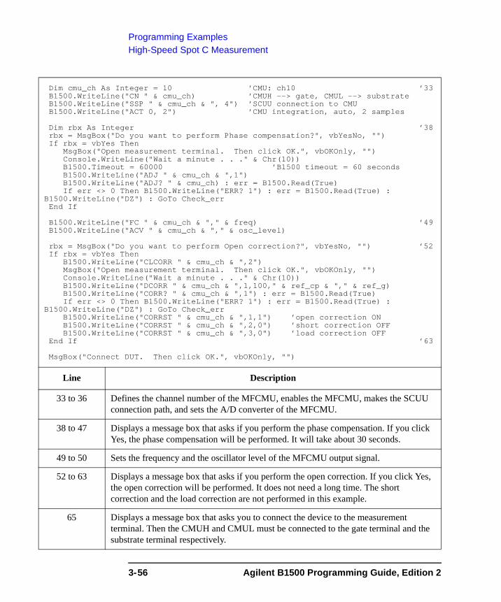
Programming ExamplesHigh-Speed Spot C Measurement
Dim cmu_ch As Integer = 10 ’CMU: ch10 ’33B1500.WriteLine("CN " & cmu_ch) ’CMUH --> gate, CMUL --> substrateB1500.WriteLine("SSP " & cmu_ch & ", 4") ’SCUU connection to CMUB1500.WriteLine("ACT 0, 2") ’CMU integration, auto, 2 samples
Dim rbx As Integer ’38rbx = MsgBox("Do you want to perform Phase compensation?", vbYesNo, "")If rbx = vbYes Then
MsgBox("Open measurement terminal. Then click OK.", vbOKOnly, "")Console.WriteLine("Wait a minute . . ." & Chr(10))B1500.Timeout = 60000 ’B1500 timeout = 60 secondsB1500.WriteLine("ADJ " & cmu_ch & ",1")B1500.WriteLine("ADJ? " & cmu_ch) : err = B1500.Read(True)If err <> 0 Then B1500.WriteLine("ERR? 1") : err = B1500.Read(True) :
B1500.WriteLine("DZ") : GoTo Check_errEnd If
B1500.WriteLine("FC " & cmu_ch & "," & freq) ’49B1500.WriteLine("ACV " & cmu_ch & "," & osc_level)
rbx = MsgBox("Do you want to perform Open correction?", vbYesNo, "") ’52If rbx = vbYes Then
B1500.WriteLine("CLCORR " & cmu_ch & ",2")MsgBox("Open measurement terminal. Then click OK.", vbOKOnly, "")Console.WriteLine("Wait a minute . . ." & Chr(10))B1500.WriteLine("DCORR " & cmu_ch & ",1,100," & ref_cp & "," & ref_g)B1500.WriteLine("CORR? " & cmu_ch & ",1") : err = B1500.Read(True)If err <> 0 Then B1500.WriteLine("ERR? 1") : err = B1500.Read(True) :
B1500.WriteLine("DZ") : GoTo Check_errB1500.WriteLine("CORRST " & cmu_ch & ",1,1") ’open correction ONB1500.WriteLine("CORRST " & cmu_ch & ",2,0") ’short correction OFFB1500.WriteLine("CORRST " & cmu_ch & ",3,0") ’load correction OFF
End If ’63
MsgBox("Connect DUT. Then click OK.", vbOKOnly, "")
Line Description
33 to 36 Defines the channel number of the MFCMU, enables the MFCMU, makes the SCUU connection path, and sets the A/D converter of the MFCMU.
38 to 47 Displays a message box that asks if you perform the phase compensation. If you click Yes, the phase compensation will be performed. It will take about 30 seconds.
49 to 50 Sets the frequency and the oscillator level of the MFCMU output signal.
52 to 63 Displays a message box that asks if you perform the open correction. If you click Yes, the open correction will be performed. It does not need a long time. The short correction and the load correction are not performed in this example.
65 Displays a message box that asks you to connect the device to the measurement terminal. Then the CMUH and CMUL must be connected to the gate terminal and the substrate terminal respectively.
3-56 Agilent B1500 Programming Guide, Edition 2
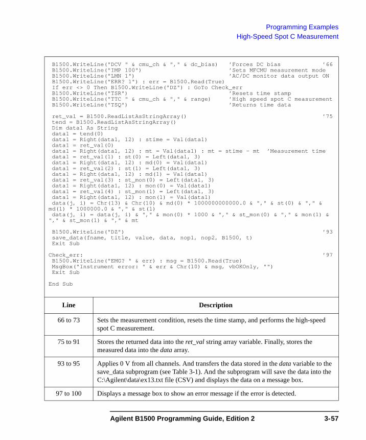
Programming ExamplesHigh-Speed Spot C Measurement
B1500.WriteLine("DCV " & cmu_ch & "," & dc_bias) ’Forces DC bias ’66B1500.WriteLine("IMP 100") ’Sets MFCMU measurement modeB1500.WriteLine("LMN 1") ’AC/DC monitor data output ONB1500.WriteLine("ERR? 1") : err = B1500.Read(True)If err <> 0 Then B1500.WriteLine("DZ") : GoTo Check_errB1500.WriteLine("TSR") ’Resets time stampB1500.WriteLine("TTC " & cmu_ch & "," & range) ’High speed spot C measurementB1500.WriteLine("TSQ") ’Returns time data
ret_val = B1500.ReadListAsStringArray() ’75tend = B1500.ReadListAsStringArray()Dim data1 As Stringdata1 = tend(0)data1 = Right(data1, 12) : stime = Val(data1)data1 = ret_val(0)data1 = Right(data1, 12) : mt = Val(data1) : mt = stime - mt ’Measurement timedata1 = ret_val(1) : st(0) = Left(data1, 3)data1 = Right(data1, 12) : md(0) = Val(data1)data1 = ret_val(2) : st(1) = Left(data1, 3)data1 = Right(data1, 12) : md(1) = Val(data1)data1 = ret_val(3) : st_mon(0) = Left(data1, 3)data1 = Right(data1, 12) : mon(0) = Val(data1)data1 = ret_val(4) : st_mon(1) = Left(data1, 3)data1 = Right(data1, 12) : mon(1) = Val(data1)data(j, i) = Chr(13) & Chr(10) & md(0) * 1000000000000.0 & "," & st(0) & "," &
md(1) * 1000000.0 & "," & st(1)data(j, i) = data(j, i) & "," & mon(0) * 1000 & "," & st_mon(0) & "," & mon(1) &
"," & st_mon(1) & "," & mt
B1500.WriteLine("DZ") ’93save_data(fname, title, value, data, nop1, nop2, B1500, t)Exit Sub
Check_err: ’97B1500.WriteLine("EMG? " & err) : msg = B1500.Read(True)MsgBox("Instrument error: " & err & Chr(10) & msg, vbOKOnly, "")Exit Sub
End Sub
Line Description
66 to 73 Sets the measurement condition, resets the time stamp, and performs the high-speed spot C measurement.
75 to 91 Stores the returned data into the ret_val string array variable. Finally, stores the measured data into the data array.
93 to 95 Applies 0 V from all channels. And transfers the data stored in the data variable to the save_data subprogram (see Table 3-1). And the subprogram will save the data into the C:\Agilent\data\ex13.txt file (CSV) and displays the data on a message box.
97 to 100 Displays a message box to show an error message if the error is detected.
Agilent B1500 Programming Guide, Edition 2 3-57
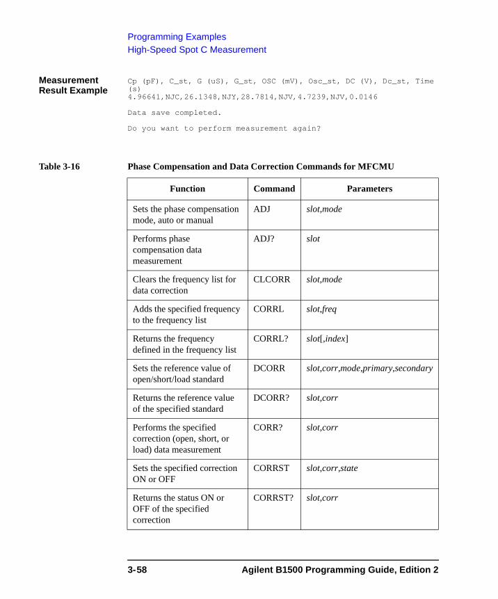
Programming ExamplesHigh-Speed Spot C Measurement
Measurement Result Example
Cp (pF), C_st, G (uS), G_st, OSC (mV), Osc_st, DC (V), Dc_st, Time (s)4.96641,NJC,26.1348,NJY,28.7814,NJV,4.7239,NJV,0.0146
Data save completed.
Do you want to perform measurement again?
Table 3-16 Phase Compensation and Data Correction Commands for MFCMU
Function Command Parameters
Sets the phase compensation mode, auto or manual
ADJ slot,mode
Performs phase compensation data measurement
ADJ? slot
Clears the frequency list for data correction
CLCORR slot,mode
Adds the specified frequency to the frequency list
CORRL slot,freq
Returns the frequency defined in the frequency list
CORRL? slot[,index]
Sets the reference value of open/short/load standard
DCORR slot,corr,mode,primary,secondary
Returns the reference value of the specified standard
DCORR? slot,corr
Performs the specified correction (open, short, or load) data measurement
CORR? slot,corr
Sets the specified correction ON or OFF
CORRST slot,corr,state
Returns the status ON or OFF of the specified correction
CORRST? slot,corr
3-58 Agilent B1500 Programming Guide, Edition 2
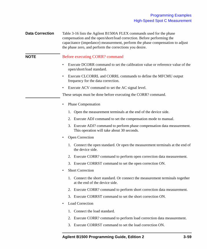
Programming ExamplesHigh-Speed Spot C Measurement
Data Correction Table 3-16 lists the Agilent B1500A FLEX commands used for the phase compensation and the open/short/load correction. Before performing the capacitance (impedance) measurement, perform the phase compensation to adjust the phase zero, and perform the corrections you desire.
NOTE Before executing CORR? command
• Execute DCORR command to set the calibration value or reference value of the open/short/load standard.
• Execute CLCORRL and CORRL commands to define the MFCMU output frequency for the data correction.
• Execute ACV command to set the AC signal level.
These setups must be done before executing the CORR? command.
• Phase Compensation
1. Open the measurement terminals at the end of the device side.
2. Execute ADJ command to set the compensation mode to manual.
3. Execute ADJ? command to perform phase compensation data measurement. This operation will take about 30 seconds.
• Open Correction
1. Connect the open standard. Or open the measurement terminals at the end of the device side.
2. Execute CORR? command to perform open correction data measurement.
3. Execute CORRST command to set the open correction ON.
• Short Correction
1. Connect the short standard. Or connect the measurement terminals together at the end of the device side.
2. Execute CORR? command to perform short correction data measurement.
3. Execute CORRST command to set the short correction ON.
• Load Correction
1. Connect the load standard.
2. Execute CORR? command to perform load correction data measurement.
3. Execute CORRST command to set the load correction ON.
Agilent B1500 Programming Guide, Edition 2 3-59
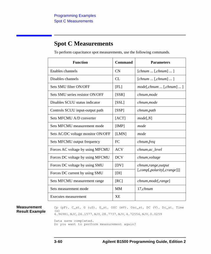
Programming ExamplesSpot C Measurements
Spot C MeasurementsTo perform capacitance spot measurements, use the following commands.
Measurement Result Example
Cp (pF), C_st, G (uS), G_st, OSC (mV), Osc_st, DC (V), Dc_st, Time (s)4.96981,NJC,26.1577,NJY,28.7737,NJV,4.72556,NJV,0.0259
Data save completed.Do you want to perform measurement again?
Function Command Parameters
Enables channels CN [chnum ... [,chnum] ... ]
Disables channels CL [chnum ... [,chnum] ... ]
Sets SMU filter ON/OFF [FL] mode[,chnum ... [,chnum] ... ]
Sets SMU series resistor ON/OFF [SSR] chnum,mode
Disables SCUU status indicator [SSL] chnum,mode
Controls SCUU input-output path [SSP] chnum,path
Sets MFCMU A/D converter [ACT] mode[,N]
Sets MFCMU measurement mode [IMP] mode
Sets AC/DC voltage monitor ON/OFF [LMN] mode
Sets MFCMU output frequency FC chnum,freq
Forces AC voltage by using MFCMU ACV chnum,ac_level
Forces DC voltage by using MFCMU DCV chnum,voltage
Forces DC voltage by using SMU [DV] chnum,range,output [,comp[,polarity[,crange]]]
Forces DC current by using SMU [DI]
Sets MFCMU measurement range [RC] chnum,mode[,range]
Sets measurement mode MM 17,chnum
Executes measurement XE
3-60 Agilent B1500 Programming Guide, Edition 2
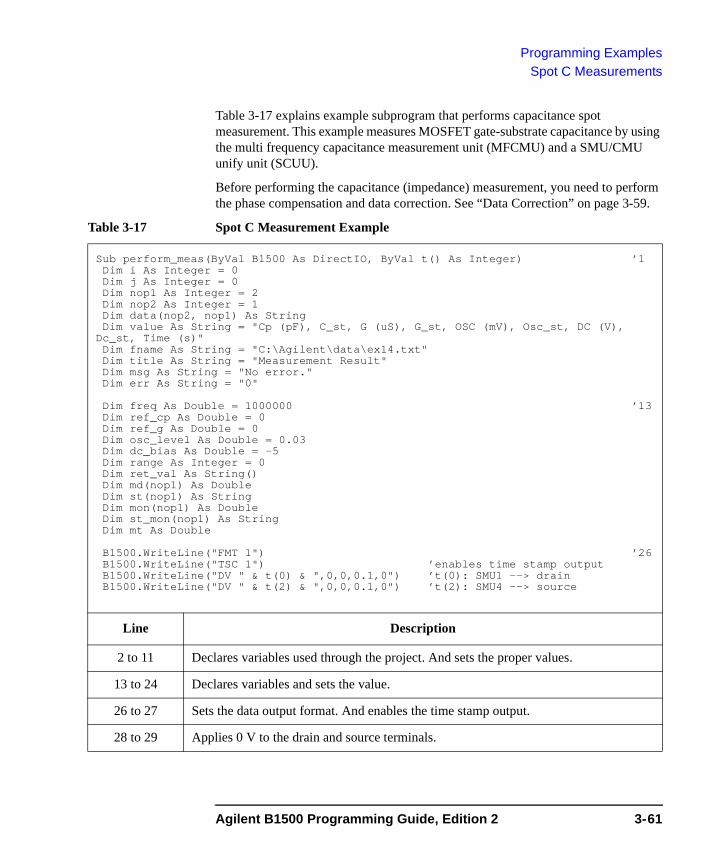
Programming ExamplesSpot C Measurements
Table 3-17 explains example subprogram that performs capacitance spot measurement. This example measures MOSFET gate-substrate capacitance by using the multi frequency capacitance measurement unit (MFCMU) and a SMU/CMU unify unit (SCUU).
Before performing the capacitance (impedance) measurement, you need to perform the phase compensation and data correction. See “Data Correction” on page 3-59.
Table 3-17 Spot C Measurement Example
Sub perform_meas(ByVal B1500 As DirectIO, ByVal t() As Integer) ’1Dim i As Integer = 0Dim j As Integer = 0Dim nop1 As Integer = 2Dim nop2 As Integer = 1Dim data(nop2, nop1) As StringDim value As String = "Cp (pF), C_st, G (uS), G_st, OSC (mV), Osc_st, DC (V),
Dc_st, Time (s)"Dim fname As String = "C:\Agilent\data\ex14.txt"Dim title As String = "Measurement Result"Dim msg As String = "No error."Dim err As String = "0"
Dim freq As Double = 1000000 ’13Dim ref_cp As Double = 0Dim ref_g As Double = 0Dim osc_level As Double = 0.03Dim dc_bias As Double = -5Dim range As Integer = 0Dim ret_val As String()Dim md(nop1) As DoubleDim st(nop1) As StringDim mon(nop1) As DoubleDim st_mon(nop1) As StringDim mt As Double
B1500.WriteLine("FMT 1") ’26B1500.WriteLine("TSC 1") ’enables time stamp outputB1500.WriteLine("DV " & t(0) & ",0,0,0.1,0") ’t(0): SMU1 --> drainB1500.WriteLine("DV " & t(2) & ",0,0,0.1,0") ’t(2): SMU4 --> source
Line Description
2 to 11 Declares variables used through the project. And sets the proper values.
13 to 24 Declares variables and sets the value.
26 to 27 Sets the data output format. And enables the time stamp output.
28 to 29 Applies 0 V to the drain and source terminals.
Agilent B1500 Programming Guide, Edition 2 3-61
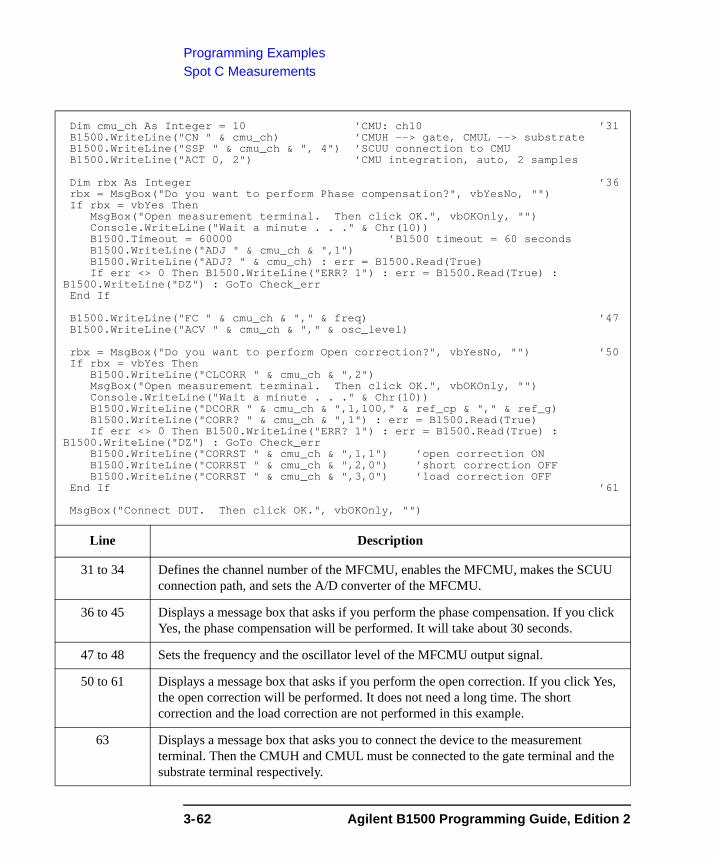
Programming ExamplesSpot C Measurements
Dim cmu_ch As Integer = 10 ’CMU: ch10 ’31B1500.WriteLine("CN " & cmu_ch) ’CMUH --> gate, CMUL --> substrateB1500.WriteLine("SSP " & cmu_ch & ", 4") ’SCUU connection to CMUB1500.WriteLine("ACT 0, 2") ’CMU integration, auto, 2 samples
Dim rbx As Integer ’36rbx = MsgBox("Do you want to perform Phase compensation?", vbYesNo, "")If rbx = vbYes Then
MsgBox("Open measurement terminal. Then click OK.", vbOKOnly, "")Console.WriteLine("Wait a minute . . ." & Chr(10))B1500.Timeout = 60000 ’B1500 timeout = 60 secondsB1500.WriteLine("ADJ " & cmu_ch & ",1")B1500.WriteLine("ADJ? " & cmu_ch) : err = B1500.Read(True)If err <> 0 Then B1500.WriteLine("ERR? 1") : err = B1500.Read(True) :
B1500.WriteLine("DZ") : GoTo Check_errEnd If
B1500.WriteLine("FC " & cmu_ch & "," & freq) ’47B1500.WriteLine("ACV " & cmu_ch & "," & osc_level)
rbx = MsgBox("Do you want to perform Open correction?", vbYesNo, "") ’50If rbx = vbYes Then
B1500.WriteLine("CLCORR " & cmu_ch & ",2")MsgBox("Open measurement terminal. Then click OK.", vbOKOnly, "")Console.WriteLine("Wait a minute . . ." & Chr(10))B1500.WriteLine("DCORR " & cmu_ch & ",1,100," & ref_cp & "," & ref_g)B1500.WriteLine("CORR? " & cmu_ch & ",1") : err = B1500.Read(True)If err <> 0 Then B1500.WriteLine("ERR? 1") : err = B1500.Read(True) :
B1500.WriteLine("DZ") : GoTo Check_errB1500.WriteLine("CORRST " & cmu_ch & ",1,1") ’open correction ONB1500.WriteLine("CORRST " & cmu_ch & ",2,0") ’short correction OFFB1500.WriteLine("CORRST " & cmu_ch & ",3,0") ’load correction OFF
End If ’61
MsgBox("Connect DUT. Then click OK.", vbOKOnly, "")
Line Description
31 to 34 Defines the channel number of the MFCMU, enables the MFCMU, makes the SCUU connection path, and sets the A/D converter of the MFCMU.
36 to 45 Displays a message box that asks if you perform the phase compensation. If you click Yes, the phase compensation will be performed. It will take about 30 seconds.
47 to 48 Sets the frequency and the oscillator level of the MFCMU output signal.
50 to 61 Displays a message box that asks if you perform the open correction. If you click Yes, the open correction will be performed. It does not need a long time. The short correction and the load correction are not performed in this example.
63 Displays a message box that asks you to connect the device to the measurement terminal. Then the CMUH and CMUL must be connected to the gate terminal and the substrate terminal respectively.
3-62 Agilent B1500 Programming Guide, Edition 2
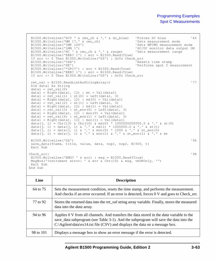
Programming ExamplesSpot C Measurements
B1500.WriteLine("DCV " & cmu_ch & "," & dc_bias) ’Forces DC bias ’64B1500.WriteLine("MM 17," & cmu_ch) ’Sets measurement modeB1500.WriteLine("IMP 100") ’Sets MFCMU measurement modeB1500.WriteLine("LMN 1") ’AC/DC monitor data output ONB1500.WriteLine("RC " & cmu_ch & "," & range) ’Sets measurement rangeB1500.WriteLine("ERR? 1") : err = B1500.Read(True)If err <> 0 Then B1500.WriteLine("DZ") : GoTo Check_errB1500.WriteLine("TSR") ’Resets time stampB1500.WriteLine("XE") ’Performs spot C measurementB1500.WriteLine("*OPC?") : err = B1500.Read(True)B1500.WriteLine("ERR? 1") : err = B1500.Read(True)If err <> 0 Then B1500.WriteLine("DZ") : GoTo Check_err
ret_val = B1500.ReadListAsStringArray() ’77Dim data1 As Stringdata1 = ret_val(0)data1 = Right(data1, 12) : mt = Val(data1)data1 = ret_val(1) : st(0) = Left(data1, 3)data1 = Right(data1, 12) : md(0) = Val(data1)data1 = ret_val(2) : st(1) = Left(data1, 3)data1 = Right(data1, 12) : md(1) = Val(data1)data1 = ret_val(3) : st_mon(0) = Left(data1, 3)data1 = Right(data1, 12) : mon(0) = Val(data1)data1 = ret_val(4) : st_mon(1) = Left(data1, 3)data1 = Right(data1, 12) : mon(1) = Val(data1)data(j, i) = Chr(13) & Chr(10) & md(0) * 1000000000000.0 & "," & st(0)data(j, i) = data(j, i) & "," & md(1) * 1000000.0 & "," & st(1)data(j, i) = data(j, i) & "," & mon(0) * 1000 & "," & st_mon(0)data(j, i) = data(j, i) & "," & mon(1) & "," & st_mon(1) & "," & mt
B1500.WriteLine("DZ") ’94save_data(fname, title, value, data, nop1, nop2, B1500, t)Exit Sub
Check_err: ’98B1500.WriteLine("EMG? " & err) : msg = B1500.Read(True)MsgBox("Instrument error: " & err & Chr(10) & msg, vbOKOnly, "")Exit Sub
End Sub
Line Description
64 to 75 Sets the measurement condition, resets the time stamp, and performs the measurement. And checks if an error occurred. If an error is detected, forces 0 V and goes to Check_err.
77 to 92 Stores the returned data into the ret_val string array variable. Finally, stores the measured data into the data array.
94 to 96 Applies 0 V from all channels. And transfers the data stored in the data variable to the save_data subprogram (see Table 3-1). And the subprogram will save the data into the C:\Agilent\data\ex14.txt file (CSV) and displays the data on a message box.
98 to 101 Displays a message box to show an error message if the error is detected.
Agilent B1500 Programming Guide, Edition 2 3-63
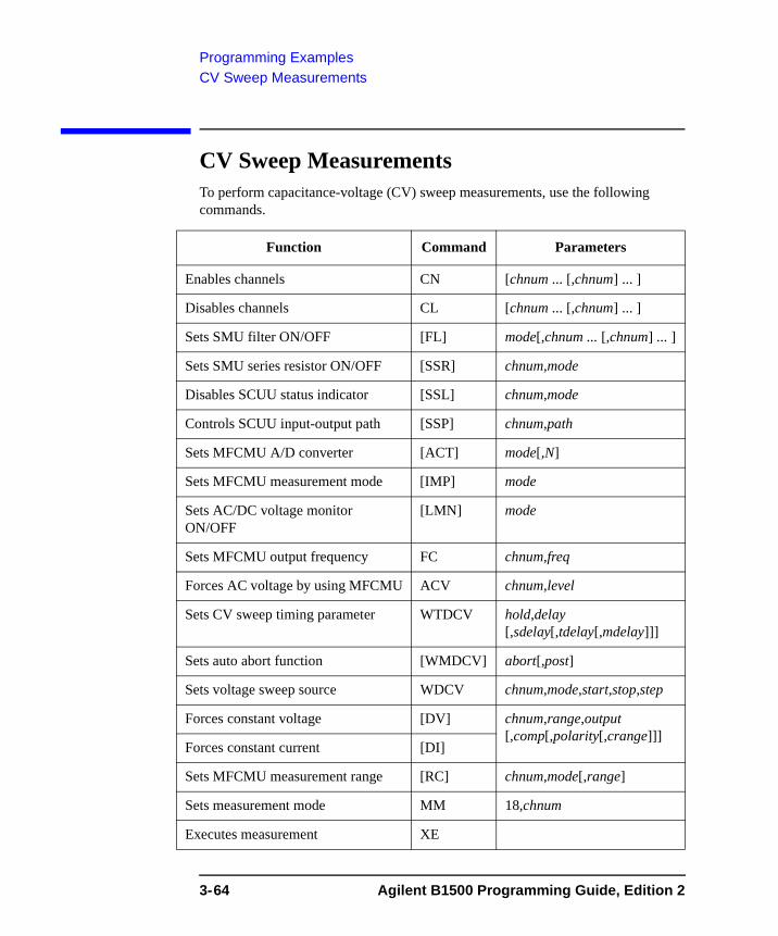
Programming ExamplesCV Sweep Measurements
CV Sweep MeasurementsTo perform capacitance-voltage (CV) sweep measurements, use the following commands.
Function Command Parameters
Enables channels CN [chnum ... [,chnum] ... ]
Disables channels CL [chnum ... [,chnum] ... ]
Sets SMU filter ON/OFF [FL] mode[,chnum ... [,chnum] ... ]
Sets SMU series resistor ON/OFF [SSR] chnum,mode
Disables SCUU status indicator [SSL] chnum,mode
Controls SCUU input-output path [SSP] chnum,path
Sets MFCMU A/D converter [ACT] mode[,N]
Sets MFCMU measurement mode [IMP] mode
Sets AC/DC voltage monitor ON/OFF
[LMN] mode
Sets MFCMU output frequency FC chnum,freq
Forces AC voltage by using MFCMU ACV chnum,level
Sets CV sweep timing parameter WTDCV hold,delay [,sdelay[,tdelay[,mdelay]]]
Sets auto abort function [WMDCV] abort[,post]
Sets voltage sweep source WDCV chnum,mode,start,stop,step
Forces constant voltage [DV] chnum,range,output [,comp[,polarity[,crange]]]
Forces constant current [DI]
Sets MFCMU measurement range [RC] chnum,mode[,range]
Sets measurement mode MM 18,chnum
Executes measurement XE
3-64 Agilent B1500 Programming Guide, Edition 2

Programming ExamplesCV Sweep Measurements
Table 3-18 explains example subprogram that performs capacitance-voltage (CV) sweep measurement. This example measures MOSFET gate-substrate capacitance by using the multi frequency capacitance measurement unit (MFCMU) and a SMU/CMU unify unit (SCUU).
Before performing the capacitance (impedance) measurement, you need to perform the phase compensation and data correction. See “Data Correction” on page 3-59.
Table 3-18 CV Sweep Measurement Example
Sub perform_meas(ByVal B1500 As DirectIO, ByVal t() As Integer) ’1Dim i As Integer = 0Dim j As Integer = 0Dim nop1 As Integer = 21Dim nop2 As Integer = 1Dim data(nop2, nop1) As StringDim value As String = "Vg (V), Cp (pF), C_st, G (uS), G_st, OSC (mV), Osc_st, DC
(V), Dc_st, Time (s)"Dim fname As String = "C:\Agilent\data\ex15.txt"Dim title As String = "CV Sweep Measurement Result"Dim msg As String = "No error."Dim err As String = "0"Dim freq As Double = 1000000 ’12Dim ref_cp As Double = 0Dim ref_g As Double = 0Dim osc_level As Double = 0.03Dim vg1 As Double = -5Dim vg2 As Double = 5Dim hold As Double = 0Dim delay As Double = 0Dim s_delay As Double = 0Dim range As Integer = 0Dim rep As Integer = nop1Dim sc(nop1) As DoubleDim md(nop1 * 2) As DoubleDim st(nop1 * 2) As StringDim mon(nop1 * 2) As DoubleDim st_mon(nop1 * 2) As StringDim tm(nop1) As DoubleDim ret_val As String()
B1500.WriteLine("FMT 1,1") ’31B1500.WriteLine("TSC 1") ’enables time stamp outputB1500.WriteLine("DV " & t(0) & ",0,0,0.1,0") ’t(0): SMU1 --> drainB1500.WriteLine("DV " & t(2) & ",0,0,0.1,0") ’t(2): SMU4 --> source
Line Description
2 to 11 Declares variables used through the project. And sets the proper values.
12 to 29 Declares variables and sets the value.
31 to 32 Sets the data output format (data with source data). And enables the time stamp output.
33 to 34 Applies 0 V to the drain and source terminals.
Agilent B1500 Programming Guide, Edition 2 3-65
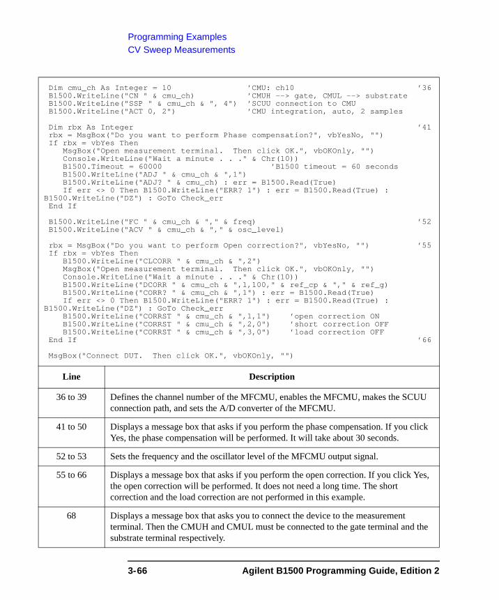
Programming ExamplesCV Sweep Measurements
Dim cmu_ch As Integer = 10 ’CMU: ch10 ’36B1500.WriteLine("CN " & cmu_ch) ’CMUH --> gate, CMUL --> substrateB1500.WriteLine("SSP " & cmu_ch & ", 4") ’SCUU connection to CMUB1500.WriteLine("ACT 0, 2") ’CMU integration, auto, 2 samples
Dim rbx As Integer ’41rbx = MsgBox("Do you want to perform Phase compensation?", vbYesNo, "")If rbx = vbYes Then
MsgBox("Open measurement terminal. Then click OK.", vbOKOnly, "")Console.WriteLine("Wait a minute . . ." & Chr(10))B1500.Timeout = 60000 ’B1500 timeout = 60 secondsB1500.WriteLine("ADJ " & cmu_ch & ",1")B1500.WriteLine("ADJ? " & cmu_ch) : err = B1500.Read(True)If err <> 0 Then B1500.WriteLine("ERR? 1") : err = B1500.Read(True) :
B1500.WriteLine("DZ") : GoTo Check_errEnd If
B1500.WriteLine("FC " & cmu_ch & "," & freq) ’52B1500.WriteLine("ACV " & cmu_ch & "," & osc_level)
rbx = MsgBox("Do you want to perform Open correction?", vbYesNo, "") ’55If rbx = vbYes Then
B1500.WriteLine("CLCORR " & cmu_ch & ",2")MsgBox("Open measurement terminal. Then click OK.", vbOKOnly, "")Console.WriteLine("Wait a minute . . ." & Chr(10))B1500.WriteLine("DCORR " & cmu_ch & ",1,100," & ref_cp & "," & ref_g)B1500.WriteLine("CORR? " & cmu_ch & ",1") : err = B1500.Read(True)If err <> 0 Then B1500.WriteLine("ERR? 1") : err = B1500.Read(True) :
B1500.WriteLine("DZ") : GoTo Check_errB1500.WriteLine("CORRST " & cmu_ch & ",1,1") ’open correction ONB1500.WriteLine("CORRST " & cmu_ch & ",2,0") ’short correction OFFB1500.WriteLine("CORRST " & cmu_ch & ",3,0") ’load correction OFF
End If ’66
MsgBox("Connect DUT. Then click OK.", vbOKOnly, "")
Line Description
36 to 39 Defines the channel number of the MFCMU, enables the MFCMU, makes the SCUU connection path, and sets the A/D converter of the MFCMU.
41 to 50 Displays a message box that asks if you perform the phase compensation. If you click Yes, the phase compensation will be performed. It will take about 30 seconds.
52 to 53 Sets the frequency and the oscillator level of the MFCMU output signal.
55 to 66 Displays a message box that asks if you perform the open correction. If you click Yes, the open correction will be performed. It does not need a long time. The short correction and the load correction are not performed in this example.
68 Displays a message box that asks you to connect the device to the measurement terminal. Then the CMUH and CMUL must be connected to the gate terminal and the substrate terminal respectively.
3-66 Agilent B1500 Programming Guide, Edition 2
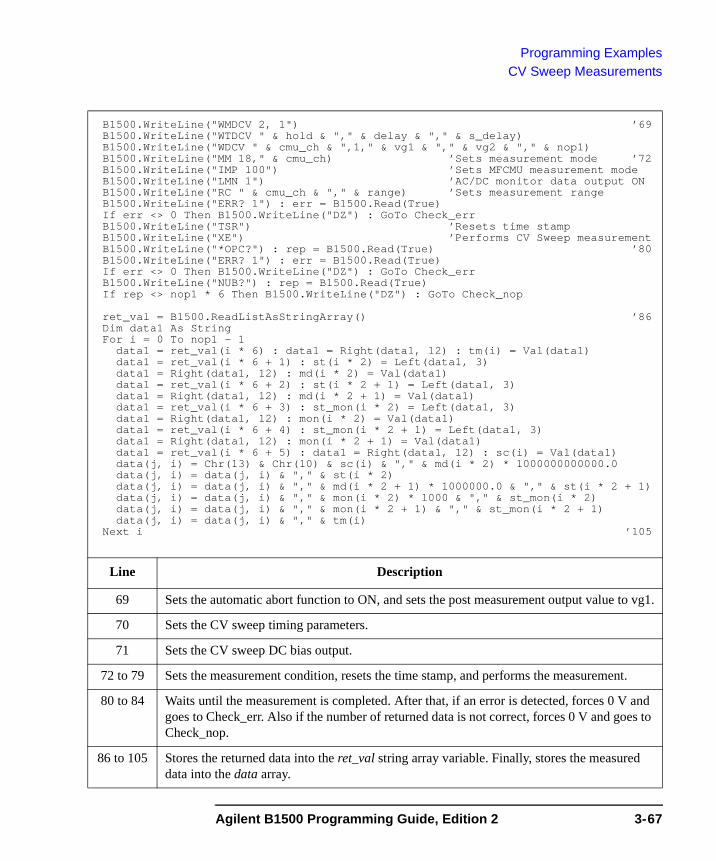
Programming ExamplesCV Sweep Measurements
B1500.WriteLine("WMDCV 2, 1") ’69B1500.WriteLine("WTDCV " & hold & "," & delay & "," & s_delay)B1500.WriteLine("WDCV " & cmu_ch & ",1," & vg1 & "," & vg2 & "," & nop1)B1500.WriteLine("MM 18," & cmu_ch) ’Sets measurement mode ’72B1500.WriteLine("IMP 100") ’Sets MFCMU measurement modeB1500.WriteLine("LMN 1") ’AC/DC monitor data output ONB1500.WriteLine("RC " & cmu_ch & "," & range) ’Sets measurement rangeB1500.WriteLine("ERR? 1") : err = B1500.Read(True)If err <> 0 Then B1500.WriteLine("DZ") : GoTo Check_errB1500.WriteLine("TSR") ’Resets time stampB1500.WriteLine("XE") ’Performs CV Sweep measurementB1500.WriteLine("*OPC?") : rep = B1500.Read(True) ’80B1500.WriteLine("ERR? 1") : err = B1500.Read(True)If err <> 0 Then B1500.WriteLine("DZ") : GoTo Check_errB1500.WriteLine("NUB?") : rep = B1500.Read(True)If rep <> nop1 * 6 Then B1500.WriteLine("DZ") : GoTo Check_nop
ret_val = B1500.ReadListAsStringArray() ’86Dim data1 As StringFor i = 0 To nop1 - 1
data1 = ret_val(i * 6) : data1 = Right(data1, 12) : tm(i) = Val(data1)data1 = ret_val(i * 6 + 1) : st(i * 2) = Left(data1, 3)data1 = Right(data1, 12) : md(i * 2) = Val(data1)data1 = ret_val(i * 6 + 2) : st(i * 2 + 1) = Left(data1, 3)data1 = Right(data1, 12) : md(i * 2 + 1) = Val(data1)data1 = ret_val(i * 6 + 3) : st_mon(i * 2) = Left(data1, 3)data1 = Right(data1, 12) : mon(i * 2) = Val(data1)data1 = ret_val(i * 6 + 4) : st_mon(i * 2 + 1) = Left(data1, 3)data1 = Right(data1, 12) : mon(i * 2 + 1) = Val(data1)data1 = ret_val(i * 6 + 5) : data1 = Right(data1, 12) : sc(i) = Val(data1)data(j, i) = Chr(13) & Chr(10) & sc(i) & "," & md(i * 2) * 1000000000000.0data(j, i) = data(j, i) & "," & st(i * 2)data(j, i) = data(j, i) & "," & md(i * 2 + 1) * 1000000.0 & "," & st(i * 2 + 1)data(j, i) = data(j, i) & "," & mon(i * 2) * 1000 & "," & st_mon(i * 2)data(j, i) = data(j, i) & "," & mon(i * 2 + 1) & "," & st_mon(i * 2 + 1)data(j, i) = data(j, i) & "," & tm(i)
Next i ’105
Line Description
69 Sets the automatic abort function to ON, and sets the post measurement output value to vg1.
70 Sets the CV sweep timing parameters.
71 Sets the CV sweep DC bias output.
72 to 79 Sets the measurement condition, resets the time stamp, and performs the measurement.
80 to 84 Waits until the measurement is completed. After that, if an error is detected, forces 0 V and goes to Check_err. Also if the number of returned data is not correct, forces 0 V and goes to Check_nop.
86 to 105 Stores the returned data into the ret_val string array variable. Finally, stores the measured data into the data array.
Agilent B1500 Programming Guide, Edition 2 3-67
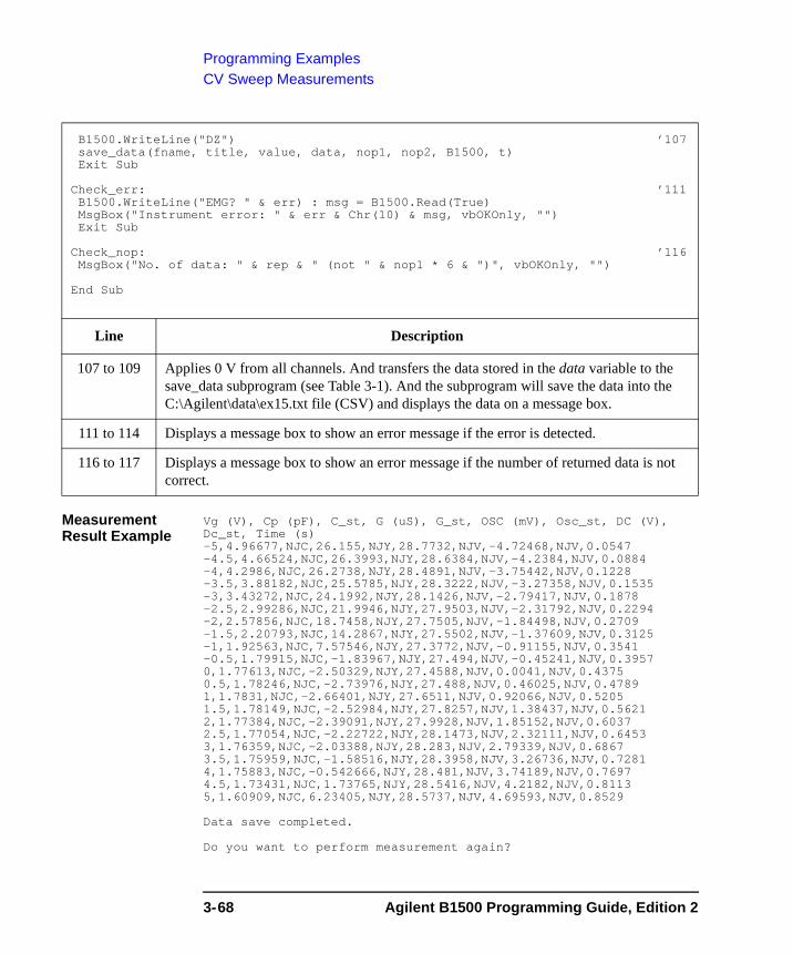
Programming ExamplesCV Sweep Measurements
Measurement Result Example
Vg (V), Cp (pF), C_st, G (uS), G_st, OSC (mV), Osc_st, DC (V), Dc_st, Time (s)-5,4.96677,NJC,26.155,NJY,28.7732,NJV,-4.72468,NJV,0.0547-4.5,4.66524,NJC,26.3993,NJY,28.6384,NJV,-4.2384,NJV,0.0884-4,4.2986,NJC,26.2738,NJY,28.4891,NJV,-3.75442,NJV,0.1228-3.5,3.88182,NJC,25.5785,NJY,28.3222,NJV,-3.27358,NJV,0.1535-3,3.43272,NJC,24.1992,NJY,28.1426,NJV,-2.79417,NJV,0.1878-2.5,2.99286,NJC,21.9946,NJY,27.9503,NJV,-2.31792,NJV,0.2294-2,2.57856,NJC,18.7458,NJY,27.7505,NJV,-1.84498,NJV,0.2709-1.5,2.20793,NJC,14.2867,NJY,27.5502,NJV,-1.37609,NJV,0.3125-1,1.92563,NJC,7.57546,NJY,27.3772,NJV,-0.91155,NJV,0.3541-0.5,1.79915,NJC,-1.83967,NJY,27.494,NJV,-0.45241,NJV,0.39570,1.77613,NJC,-2.50329,NJY,27.4588,NJV,0.0041,NJV,0.43750.5,1.78246,NJC,-2.73976,NJY,27.488,NJV,0.46025,NJV,0.47891,1.7831,NJC,-2.66401,NJY,27.6511,NJV,0.92066,NJV,0.52051.5,1.78149,NJC,-2.52984,NJY,27.8257,NJV,1.38437,NJV,0.56212,1.77384,NJC,-2.39091,NJY,27.9928,NJV,1.85152,NJV,0.60372.5,1.77054,NJC,-2.22722,NJY,28.1473,NJV,2.32111,NJV,0.64533,1.76359,NJC,-2.03388,NJY,28.283,NJV,2.79339,NJV,0.68673.5,1.75959,NJC,-1.58516,NJY,28.3958,NJV,3.26736,NJV,0.72814,1.75883,NJC,-0.542666,NJY,28.481,NJV,3.74189,NJV,0.76974.5,1.73431,NJC,1.73765,NJY,28.5416,NJV,4.2182,NJV,0.81135,1.60909,NJC,6.23405,NJY,28.5737,NJV,4.69593,NJV,0.8529
Data save completed.
Do you want to perform measurement again?
B1500.WriteLine("DZ") ’107save_data(fname, title, value, data, nop1, nop2, B1500, t)Exit Sub
Check_err: ’111B1500.WriteLine("EMG? " & err) : msg = B1500.Read(True)MsgBox("Instrument error: " & err & Chr(10) & msg, vbOKOnly, "")Exit Sub
Check_nop: ’116MsgBox("No. of data: " & rep & " (not " & nop1 * 6 & ")", vbOKOnly, "")
End Sub
Line Description
107 to 109 Applies 0 V from all channels. And transfers the data stored in the data variable to the save_data subprogram (see Table 3-1). And the subprogram will save the data into the C:\Agilent\data\ex15.txt file (CSV) and displays the data on a message box.
111 to 114 Displays a message box to show an error message if the error is detected.
116 to 117 Displays a message box to show an error message if the number of returned data is not correct.
3-68 Agilent B1500 Programming Guide, Edition 2
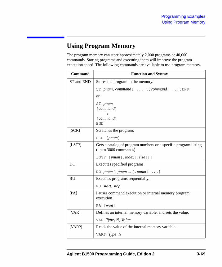
Programming ExamplesUsing Program Memory
Using Program Memory The program memory can store approximately 2,000 programs or 40,000 commands. Storing programs and executing them will improve the program execution speed. The following commands are available to use program memory.
Command Function and Syntax
ST and END Stores the program in the memory.
ST pnum;command[ ... [;command] ..];END
or
ST pnum[command]
:[command]END
[SCR] Scratches the program.
SCR [pnum]
[LST?] Gets a catalog of program numbers or a specific program listing (up to 3000 commands).
LST? [pnum[,index[,size]]]
DO Executes specified programs.
DO pnum[,pnum ... [,pnum] ...]
RU Executes programs sequentially.
RU start,stop
[PA] Pauses command execution or internal memory program execution.
PA [wait]
[VAR] Defines an internal memory variable, and sets the value.
VAR Type,N,Value
[VAR?] Reads the value of the internal memory variable.
VAR? Type,N
Agilent B1500 Programming Guide, Edition 2 3-69
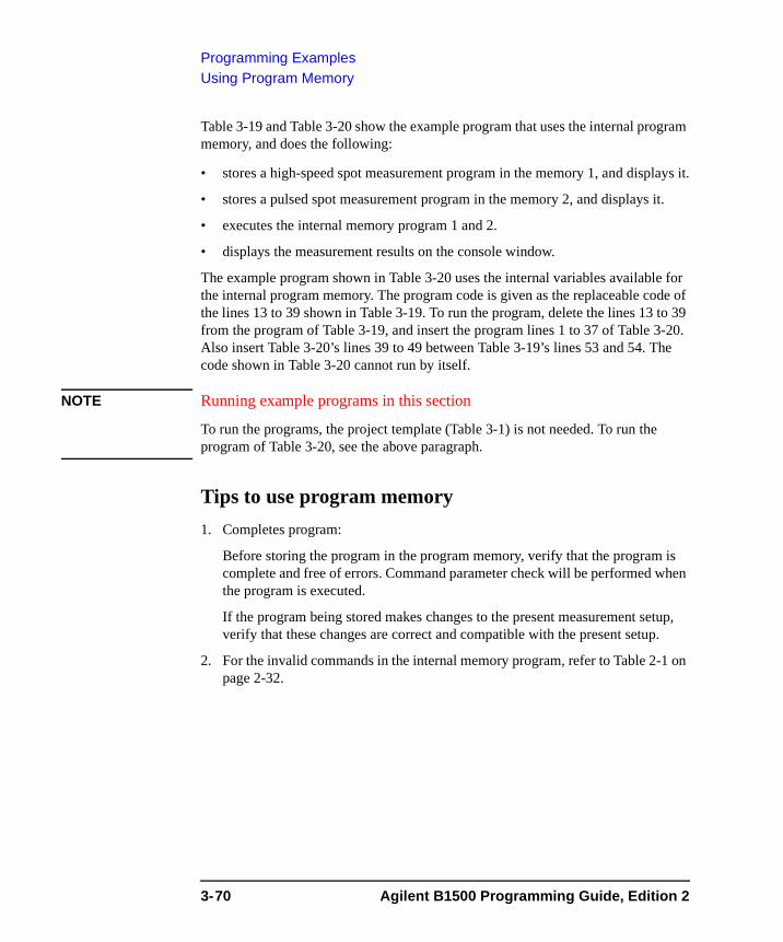
Programming ExamplesUsing Program Memory
Table 3-19 and Table 3-20 show the example program that uses the internal program memory, and does the following:
• stores a high-speed spot measurement program in the memory 1, and displays it.
• stores a pulsed spot measurement program in the memory 2, and displays it.
• executes the internal memory program 1 and 2.
• displays the measurement results on the console window.
The example program shown in Table 3-20 uses the internal variables available for the internal program memory. The program code is given as the replaceable code of the lines 13 to 39 shown in Table 3-19. To run the program, delete the lines 13 to 39 from the program of Table 3-19, and insert the program lines 1 to 37 of Table 3-20. Also insert Table 3-20’s lines 39 to 49 between Table 3-19’s lines 53 and 54. The code shown in Table 3-20 cannot run by itself.
NOTE Running example programs in this section
To run the programs, the project template (Table 3-1) is not needed. To run the program of Table 3-20, see the above paragraph.
Tips to use program memory1. Completes program:
Before storing the program in the program memory, verify that the program is complete and free of errors. Command parameter check will be performed when the program is executed.
If the program being stored makes changes to the present measurement setup, verify that these changes are correct and compatible with the present setup.
2. For the invalid commands in the internal memory program, refer to Table 2-1 on page 2-32.
3-70 Agilent B1500 Programming Guide, Edition 2
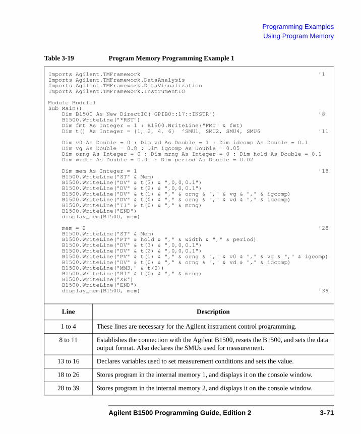
Programming ExamplesUsing Program Memory
Table 3-19 Program Memory Programming Example 1
Imports Agilent.TMFramework ’1Imports Agilent.TMFramework.DataAnalysisImports Agilent.TMFramework.DataVisualizationImports Agilent.TMFramework.InstrumentIO
Module Module1Sub Main()
Dim B1500 As New DirectIO("GPIB0::17::INSTR") ’8B1500.WriteLine("*RST")Dim fmt As Integer = 1 : B1500.WriteLine("FMT" & fmt)Dim t() As Integer = {1, 2, 4, 6} ’SMU1, SMU2, SMU4, SMU6 ’11
Dim v0 As Double = 0 : Dim vd As Double = 1 : Dim idcomp As Double = 0.1Dim vg As Double = 0.8 : Dim igcomp As Double = 0.05Dim orng As Integer = 0 : Dim mrng As Integer = 0 : Dim hold As Double = 0.1Dim width As Double = 0.01 : Dim period As Double = 0.02
Dim mem As Integer = 1 ’18B1500.WriteLine("ST" & Mem)B1500.WriteLine("DV" & t(3) & ",0,0,0.1")B1500.WriteLine("DV" & t(2) & ",0,0,0.1")B1500.WriteLine("DV" & t(1) & "," & orng & "," & vg & "," & igcomp)B1500.WriteLine("DV" & t(0) & "," & orng & "," & vd & "," & idcomp)B1500.WriteLine("TI" & t(0) & "," & mrng)B1500.WriteLine("END")display_mem(B1500, mem)
mem = 2 ’28B1500.WriteLine("ST" & Mem)B1500.WriteLine("PT" & hold & "," & width & "," & period)B1500.WriteLine("DV" & t(3) & ",0,0,0.1")B1500.WriteLine("DV" & t(2) & ",0,0,0.1")B1500.WriteLine("PV" & t(1) & "," & orng & "," & v0 & "," & vg & "," & igcomp)B1500.WriteLine("DV" & t(0) & "," & orng & "," & vd & "," & idcomp)B1500.WriteLine("MM3," & t(0))B1500.WriteLine("RI" & t(0) & "," & mrng)B1500.WriteLine("XE")B1500.WriteLine("END")display_mem(B1500, mem) ’39
Line Description
1 to 4 These lines are necessary for the Agilent instrument control programming.
8 to 11 Establishes the connection with the Agilent B1500, resets the B1500, and sets the data output format. Also declares the SMUs used for measurement.
13 to 16 Declares variables used to set measurement conditions and sets the value.
18 to 26 Stores program in the internal memory 1, and displays it on the console window.
28 to 39 Stores program in the internal memory 2, and displays it on the console window.
Agilent B1500 Programming Guide, Edition 2 3-71
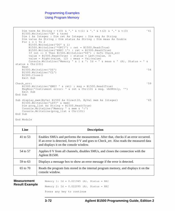
Programming ExamplesUsing Program Memory
Measurement Result Example
Memory 1: Id = 0.021945 (A), Status = NAI
Memory 2: Id = 0.022095 (A), Status = NAI
Press any key to continue
Dim term As String = t(0) & "," & t(1) & "," & t(2) & "," & t(3) ’41B1500.WriteLine("CN" & term)Dim i As Integer : Dim ret As Integer : Dim msg As StringDim value As String : Dim status As String : Dim meas As DoubleFor i = 1 To 2
B1500.WriteLine("DO" & i)B1500.WriteLine("*OPC?") : ret = B1500.Read(True)B1500.WriteLine("ERR? 1") : ret = B1500.Read(True)If ret <> 0 Then B1500.WriteLine("DZ") : GoTo Check_errvalue = B1500.Read(True) : status = Left(value, 3)value = Right(value, 12) : meas = Val(value)Console.WriteLine("Memory " & i & ": Id = " & meas & " (A), Status = " &
status & Chr(10))NextB1500.WriteLine("DZ") ’54B1500.WriteLine("CL")B1500.Close()Exit Sub
Check_err: ’59B1500.WriteLine("EMG? " & ret) : msg = B1500.Read(True)MsgBox("Instrument error: " & ret & Chr(10) & msg, vbOKOnly, "")Exit Sub
End Sub
Sub display_mem(ByVal B1500 As DirectIO, ByVal mem As Integer) ’65B1500.WriteLine("LST?" & mem)Dim prog_list As String = B1500.Read(True)Console.WriteLine("Memory " & mem & ":")Console.WriteLine(prog_list & Chr(10))
End Sub
End Module
Line Description
41 to 53 Enables SMUs and performs the measurement. After that, checks if an error occurred. If an error is detected, forces 0 V and goes to Check_err. Also reads the measured data and displays it on the console window.
54 to 57 Applies 0 V from all channels, disables SMUs, and closes the connection with the Agilent B1500.
59 to 63 Displays a message box to show an error message if the error is detected.
65 to 70 Reads the program lists stored in the internal program memory, and displays it on the console window.
3-72 Agilent B1500 Programming Guide, Edition 2
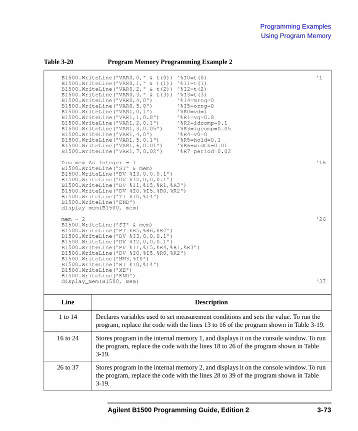
Programming ExamplesUsing Program Memory
Table 3-20 Program Memory Programming Example 2
B1500.WriteLine("VAR0,0," & t(0)) ’%I0=t(0) ’1B1500.WriteLine("VAR0,1," & t(1)) ’%I1=t(1)B1500.WriteLine("VAR0,2," & t(2)) ’%I2=t(2)B1500.WriteLine("VAR0,3," & t(3)) ’%I3=t(3)B1500.WriteLine("VAR0,4,0") ’%I4=mrng=0B1500.WriteLine("VAR0,5,0") ’%I5=orng=0B1500.WriteLine("VAR1,0,1") ’%R0=vd=1B1500.WriteLine("VAR1,1,0.8") ’%R1=vg=0.8B1500.WriteLine("VAR1,2,0.1") ’%R2=idcomp=0.1B1500.WriteLine("VAR1,3,0.05") ’%R3=igcomp=0.05B1500.WriteLine("VAR1,4,0") ’%R4=v0=0B1500.WriteLine("VAR1,5,0.1") ’%R5=hold=0.1B1500.WriteLine("VAR1,6,0.01") ’%R6=width=0.01B1500.WriteLine("VAR1,7,0.02") ’%R7=period=0.02
Dim mem As Integer = 1 ’16B1500.WriteLine("ST" & mem)B1500.WriteLine("DV %I3,0,0,0.1")B1500.WriteLine("DV %I2,0,0,0.1")B1500.WriteLine("DV %I1,%I5,%R1,%R3")B1500.WriteLine("DV %I0,%I5,%R0,%R2")B1500.WriteLine("TI %I0,%I4")B1500.WriteLine("END")display_mem(B1500, mem)
mem = 2 ’26B1500.WriteLine("ST" & mem)B1500.WriteLine("PT %R5,%R6,%R7")B1500.WriteLine("DV %I3,0,0,0.1")B1500.WriteLine("DV %I2,0,0,0.1")B1500.WriteLine("PV %I1,%I5,%R4,%R1,%R3")B1500.WriteLine("DV %I0,%I5,%R0,%R2")B1500.WriteLine("MM3,%I0")B1500.WriteLine("RI %I0,%I4")B1500.WriteLine("XE")B1500.WriteLine("END")display_mem(B1500, mem) ’37
Line Description
1 to 14 Declares variables used to set measurement conditions and sets the value. To run the program, replace the code with the lines 13 to 16 of the program shown in Table 3-19.
16 to 24 Stores program in the internal memory 1, and displays it on the console window. To run the program, replace the code with the lines 18 to 26 of the program shown in Table 3-19.
26 to 37 Stores program in the internal memory 2, and displays it on the console window. To run the program, replace the code with the lines 28 to 39 of the program shown in Table 3-19.
Agilent B1500 Programming Guide, Edition 2 3-73
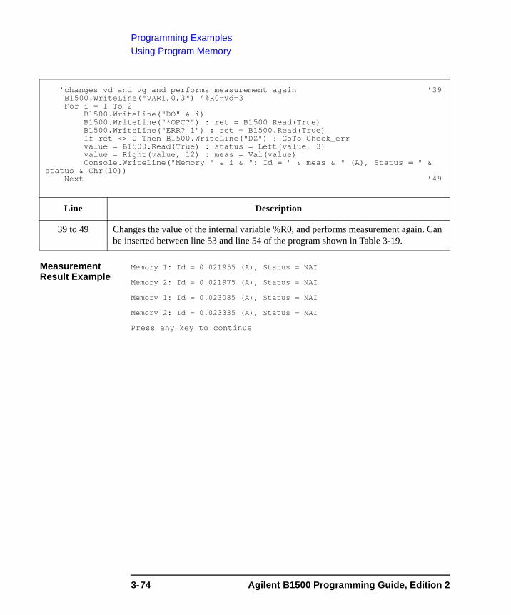
Programming ExamplesUsing Program Memory
Measurement Result Example
Memory 1: Id = 0.021955 (A), Status = NAI
Memory 2: Id = 0.021975 (A), Status = NAI
Memory 1: Id = 0.023085 (A), Status = NAI
Memory 2: Id = 0.023335 (A), Status = NAI
Press any key to continue
’changes vd and vg and performs measurement again ’39B1500.WriteLine("VAR1,0,3") ’%R0=vd=3For i = 1 To 2
B1500.WriteLine("DO" & i)B1500.WriteLine("*OPC?") : ret = B1500.Read(True)B1500.WriteLine("ERR? 1") : ret = B1500.Read(True)If ret <> 0 Then B1500.WriteLine("DZ") : GoTo Check_errvalue = B1500.Read(True) : status = Left(value, 3)value = Right(value, 12) : meas = Val(value)Console.WriteLine("Memory " & i & ": Id = " & meas & " (A), Status = " &
status & Chr(10))Next ’49
Line Description
39 to 49 Changes the value of the internal variable %R0, and performs measurement again. Can be inserted between line 53 and line 54 of the program shown in Table 3-19.
3-74 Agilent B1500 Programming Guide, Edition 2
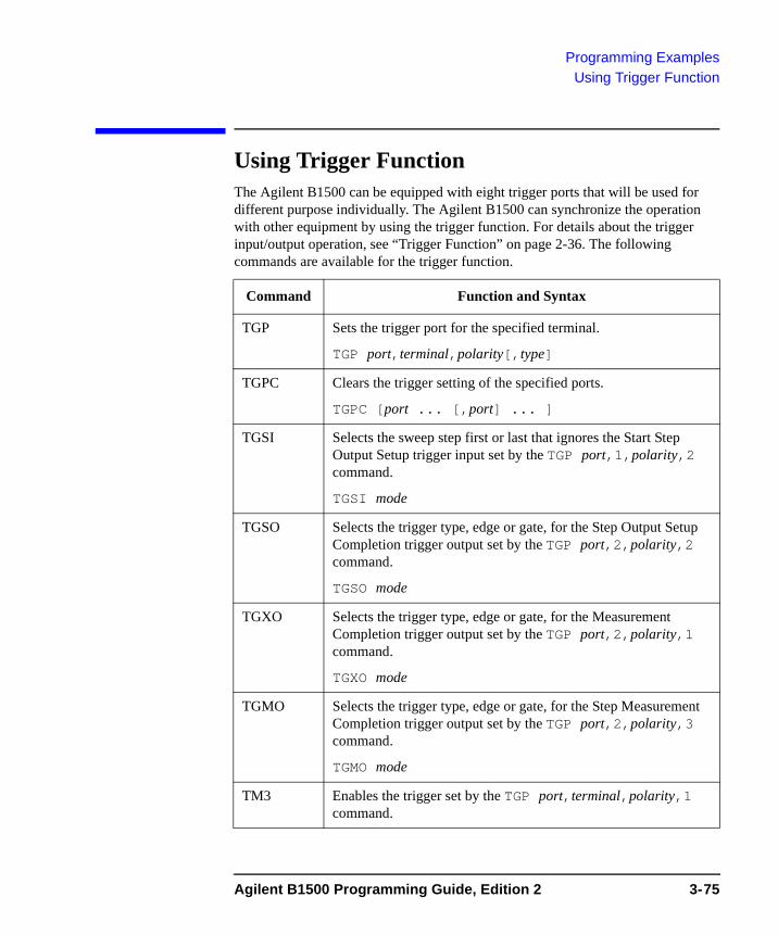
Programming ExamplesUsing Trigger Function
Using Trigger FunctionThe Agilent B1500 can be equipped with eight trigger ports that will be used for different purpose individually. The Agilent B1500 can synchronize the operation with other equipment by using the trigger function. For details about the trigger input/output operation, see “Trigger Function” on page 2-36. The following commands are available for the trigger function.
Command Function and Syntax
TGP Sets the trigger port for the specified terminal.
TGP port,terminal,polarity[,type]
TGPC Clears the trigger setting of the specified ports.
TGPC [port ... [,port] ... ]
TGSI Selects the sweep step first or last that ignores the Start Step Output Setup trigger input set by the TGP port,1,polarity,2 command.
TGSI mode
TGSO Selects the trigger type, edge or gate, for the Step Output Setup Completion trigger output set by the TGP port,2,polarity,2 command.
TGSO mode
TGXO Selects the trigger type, edge or gate, for the Measurement Completion trigger output set by the TGP port,2,polarity,1 command.
TGXO mode
TGMO Selects the trigger type, edge or gate, for the Step Measurement Completion trigger output set by the TGP port,2,polarity,3 command.
TGMO mode
TM3 Enables the trigger set by the TGP port,terminal,polarity,1 command.
Agilent B1500 Programming Guide, Edition 2 3-75
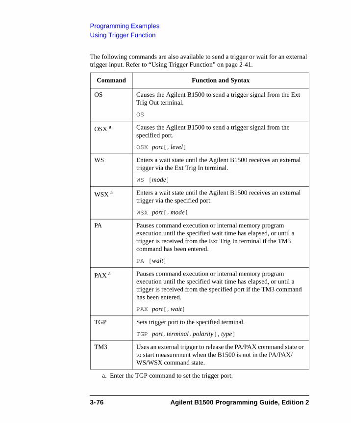
Programming ExamplesUsing Trigger Function
The following commands are also available to send a trigger or wait for an external trigger input. Refer to “Using Trigger Function” on page 2-41.
Command Function and Syntax
OS Causes the Agilent B1500 to send a trigger signal from the Ext Trig Out terminal.
OS
OSX a
a. Enter the TGP command to set the trigger port.
Causes the Agilent B1500 to send a trigger signal from the specified port.
OSX port[,level]
WS Enters a wait state until the Agilent B1500 receives an external trigger via the Ext Trig In terminal.
WS [mode]
WSX a Enters a wait state until the Agilent B1500 receives an external trigger via the specified port.
WSX port[,mode]
PA Pauses command execution or internal memory program execution until the specified wait time has elapsed, or until a trigger is received from the Ext Trig In terminal if the TM3 command has been entered.
PA [wait]
PAX a Pauses command execution or internal memory program execution until the specified wait time has elapsed, or until a trigger is received from the specified port if the TM3 command has been entered.
PAX port[,wait]
TGP Sets trigger port to the specified terminal.
TGP port,terminal,polarity[,type]
TM3 Uses an external trigger to release the PA/PAX command state or to start measurement when the B1500 is not in the PA/PAX/ WS/WSX command state.
3-76 Agilent B1500 Programming Guide, Edition 2
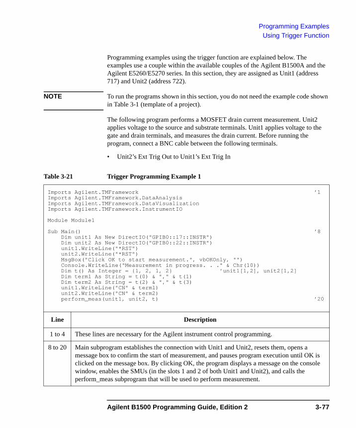
Programming ExamplesUsing Trigger Function
Programming examples using the trigger function are explained below. The examples use a couple within the available couples of the Agilent B1500A and the Agilent E5260/E5270 series. In this section, they are assigned as Unit1 (address 717) and Unit2 (address 722).
NOTE To run the programs shown in this section, you do not need the example code shown in Table 3-1 (template of a project).
The following program performs a MOSFET drain current measurement. Unit2 applies voltage to the source and substrate terminals. Unit1 applies voltage to the gate and drain terminals, and measures the drain current. Before running the program, connect a BNC cable between the following terminals.
• Unit2’s Ext Trig Out to Unit1’s Ext Trig In
Table 3-21 Trigger Programming Example 1
Imports Agilent.TMFramework ’1Imports Agilent.TMFramework.DataAnalysisImports Agilent.TMFramework.DataVisualizationImports Agilent.TMFramework.InstrumentIO
Module Module1
Sub Main() ’8Dim unit1 As New DirectIO("GPIB0::17::INSTR")Dim unit2 As New DirectIO("GPIB0::22::INSTR")unit1.WriteLine("*RST")unit2.WriteLine("*RST")MsgBox("Click OK to start measurement.", vbOKOnly, "")Console.WriteLine("Measurement in progress. . ." & Chr(10))Dim t() As Integer = {1, 2, 1, 2} ’unit1[1,2], unit2[1,2]Dim term1 As String = t(0) & "," & t(1)Dim term2 As String = t(2) & "," & t(3)unit1.WriteLine("CN" & term1)unit2.WriteLine("CN" & term2)perform_meas(unit1, unit2, t) ’20
Line Description
1 to 4 These lines are necessary for the Agilent instrument control programming.
8 to 20 Main subprogram establishes the connection with Unit1 and Unit2, resets them, opens a message box to confirm the start of measurement, and pauses program execution until OK is clicked on the message box. By clicking OK, the program displays a message on the console window, enables the SMUs (in the slots 1 and 2 of both Unit1 and Unit2), and calls the perform_meas subprogram that will be used to perform measurement.
Agilent B1500 Programming Guide, Edition 2 3-77
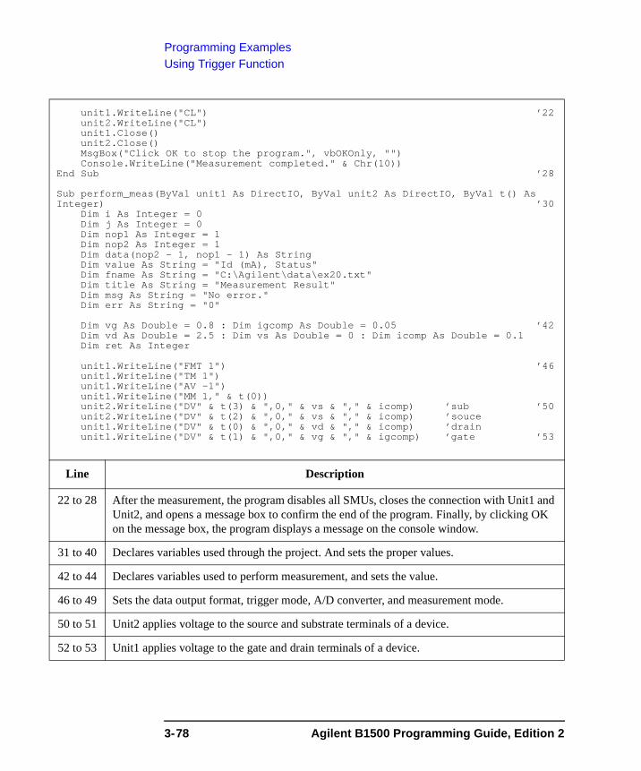
Programming ExamplesUsing Trigger Function
unit1.WriteLine("CL") ’22unit2.WriteLine("CL")unit1.Close()unit2.Close()MsgBox("Click OK to stop the program.", vbOKOnly, "")Console.WriteLine("Measurement completed." & Chr(10))
End Sub ’28
Sub perform_meas(ByVal unit1 As DirectIO, ByVal unit2 As DirectIO, ByVal t() As Integer) ’30
Dim i As Integer = 0Dim j As Integer = 0Dim nop1 As Integer = 1Dim nop2 As Integer = 1Dim data(nop2 - 1, nop1 - 1) As StringDim value As String = "Id (mA), Status"Dim fname As String = "C:\Agilent\data\ex20.txt"Dim title As String = "Measurement Result"Dim msg As String = "No error."Dim err As String = "0"
Dim vg As Double = 0.8 : Dim igcomp As Double = 0.05 ’42Dim vd As Double = 2.5 : Dim vs As Double = 0 : Dim icomp As Double = 0.1Dim ret As Integer
unit1.WriteLine("FMT 1") ’46unit1.WriteLine("TM 1")unit1.WriteLine("AV -1")unit1.WriteLine("MM 1," & t(0))unit2.WriteLine("DV" & t(3) & ",0," & vs & "," & icomp) ’sub ’50unit2.WriteLine("DV" & t(2) & ",0," & vs & "," & icomp) ’souceunit1.WriteLine("DV" & t(0) & ",0," & vd & "," & icomp) ’drainunit1.WriteLine("DV" & t(1) & ",0," & vg & "," & igcomp) ’gate ’53
Line Description
22 to 28 After the measurement, the program disables all SMUs, closes the connection with Unit1 and Unit2, and opens a message box to confirm the end of the program. Finally, by clicking OK on the message box, the program displays a message on the console window.
31 to 40 Declares variables used through the project. And sets the proper values.
42 to 44 Declares variables used to perform measurement, and sets the value.
46 to 49 Sets the data output format, trigger mode, A/D converter, and measurement mode.
50 to 51 Unit2 applies voltage to the source and substrate terminals of a device.
52 to 53 Unit1 applies voltage to the gate and drain terminals of a device.
3-78 Agilent B1500 Programming Guide, Edition 2
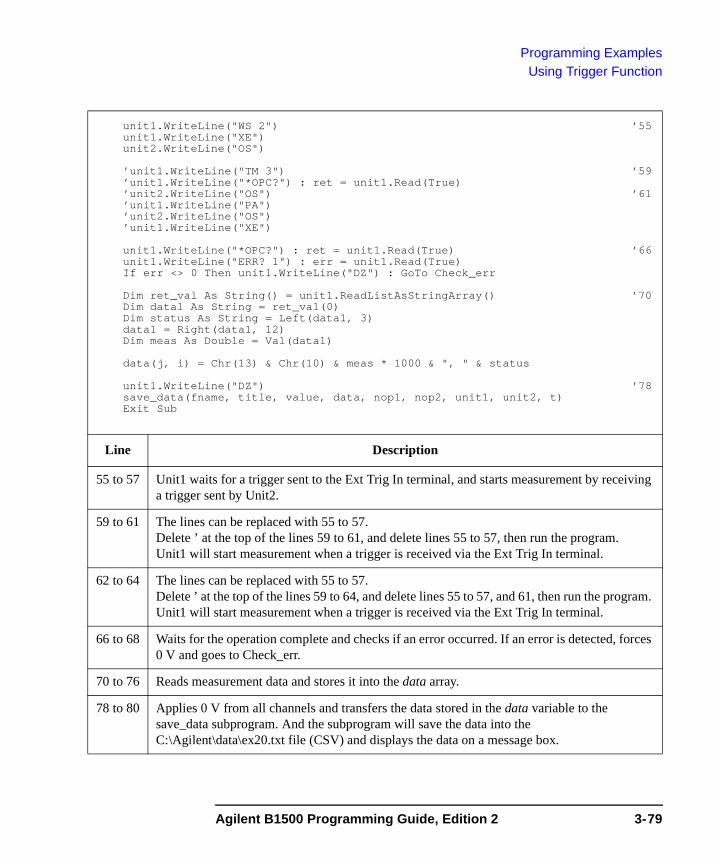
Programming ExamplesUsing Trigger Function
unit1.WriteLine("WS 2") ’55unit1.WriteLine("XE")unit2.WriteLine("OS")
’unit1.WriteLine("TM 3") ’59’unit1.WriteLine("*OPC?") : ret = unit1.Read(True)’unit2.WriteLine("OS") ’61’unit1.WriteLine("PA")’unit2.WriteLine("OS")’unit1.WriteLine("XE")
unit1.WriteLine("*OPC?") : ret = unit1.Read(True) ’66unit1.WriteLine("ERR? 1") : err = unit1.Read(True)If err <> 0 Then unit1.WriteLine("DZ") : GoTo Check_err
Dim ret_val As String() = unit1.ReadListAsStringArray() ’70Dim data1 As String = ret_val(0)Dim status As String = Left(data1, 3)data1 = Right(data1, 12)Dim meas As Double = Val(data1)
data(j, i) = Chr(13) & Chr(10) & meas * 1000 & ", " & status
unit1.WriteLine("DZ") ’78save_data(fname, title, value, data, nop1, nop2, unit1, unit2, t)Exit Sub
Line Description
55 to 57 Unit1 waits for a trigger sent to the Ext Trig In terminal, and starts measurement by receiving a trigger sent by Unit2.
59 to 61 The lines can be replaced with 55 to 57.Delete ’ at the top of the lines 59 to 61, and delete lines 55 to 57, then run the program.Unit1 will start measurement when a trigger is received via the Ext Trig In terminal.
62 to 64 The lines can be replaced with 55 to 57.Delete ’ at the top of the lines 59 to 64, and delete lines 55 to 57, and 61, then run the program. Unit1 will start measurement when a trigger is received via the Ext Trig In terminal.
66 to 68 Waits for the operation complete and checks if an error occurred. If an error is detected, forces 0 V and goes to Check_err.
70 to 76 Reads measurement data and stores it into the data array.
78 to 80 Applies 0 V from all channels and transfers the data stored in the data variable to the save_data subprogram. And the subprogram will save the data into the C:\Agilent\data\ex20.txt file (CSV) and displays the data on a message box.
Agilent B1500 Programming Guide, Edition 2 3-79
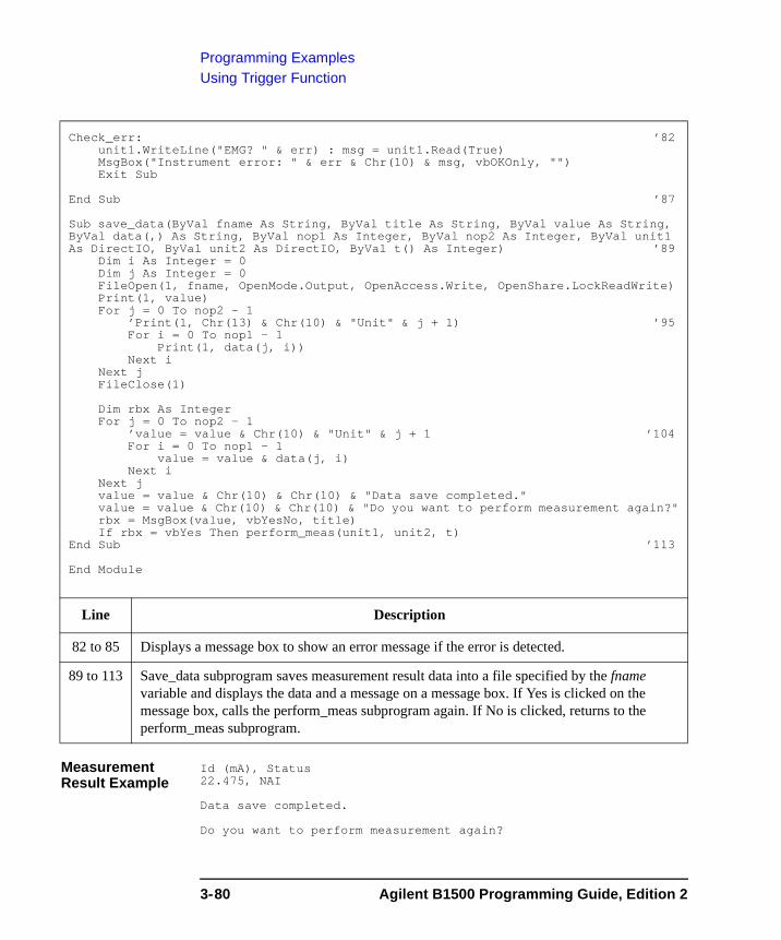
Programming ExamplesUsing Trigger Function
Measurement Result Example
Id (mA), Status22.475, NAI
Data save completed.
Do you want to perform measurement again?
Check_err: ’82unit1.WriteLine("EMG? " & err) : msg = unit1.Read(True)MsgBox("Instrument error: " & err & Chr(10) & msg, vbOKOnly, "")Exit Sub
End Sub ’87
Sub save_data(ByVal fname As String, ByVal title As String, ByVal value As String, ByVal data(,) As String, ByVal nop1 As Integer, ByVal nop2 As Integer, ByVal unit1 As DirectIO, ByVal unit2 As DirectIO, ByVal t() As Integer) ’89
Dim i As Integer = 0Dim j As Integer = 0FileOpen(1, fname, OpenMode.Output, OpenAccess.Write, OpenShare.LockReadWrite)Print(1, value)For j = 0 To nop2 - 1
’Print(1, Chr(13) & Chr(10) & "Unit" & j + 1) ’95For i = 0 To nop1 - 1
Print(1, data(j, i))Next i
Next jFileClose(1)
Dim rbx As IntegerFor j = 0 To nop2 - 1
’value = value & Chr(10) & "Unit" & j + 1 ’104For i = 0 To nop1 - 1
value = value & data(j, i)Next i
Next jvalue = value & Chr(10) & Chr(10) & "Data save completed."value = value & Chr(10) & Chr(10) & "Do you want to perform measurement again?"rbx = MsgBox(value, vbYesNo, title)If rbx = vbYes Then perform_meas(unit1, unit2, t)
End Sub ’113
End Module
Line Description
82 to 85 Displays a message box to show an error message if the error is detected.
89 to 113 Save_data subprogram saves measurement result data into a file specified by the fname variable and displays the data and a message on a message box. If Yes is clicked on the message box, calls the perform_meas subprogram again. If No is clicked, returns to the perform_meas subprogram.
3-80 Agilent B1500 Programming Guide, Edition 2
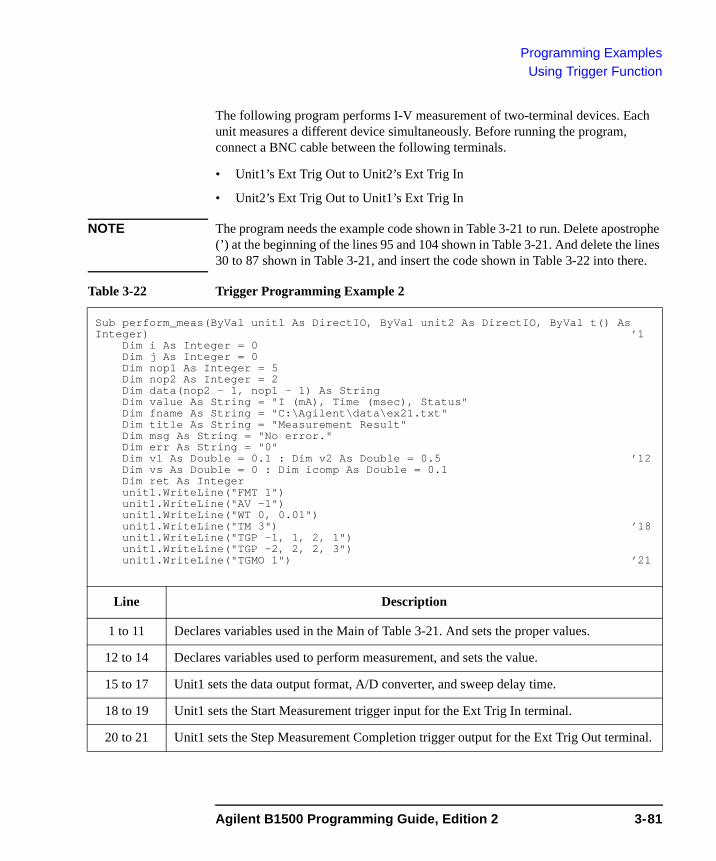
Programming ExamplesUsing Trigger Function
The following program performs I-V measurement of two-terminal devices. Each unit measures a different device simultaneously. Before running the program, connect a BNC cable between the following terminals.
• Unit1’s Ext Trig Out to Unit2’s Ext Trig In
• Unit2’s Ext Trig Out to Unit1’s Ext Trig In
NOTE The program needs the example code shown in Table 3-21 to run. Delete apostrophe (’) at the beginning of the lines 95 and 104 shown in Table 3-21. And delete the lines 30 to 87 shown in Table 3-21, and insert the code shown in Table 3-22 into there.
Table 3-22 Trigger Programming Example 2
Sub perform_meas(ByVal unit1 As DirectIO, ByVal unit2 As DirectIO, ByVal t() As Integer) ’1
Dim i As Integer = 0Dim j As Integer = 0Dim nop1 As Integer = 5Dim nop2 As Integer = 2Dim data(nop2 - 1, nop1 - 1) As StringDim value As String = "I (mA), Time (msec), Status"Dim fname As String = "C:\Agilent\data\ex21.txt"Dim title As String = "Measurement Result"Dim msg As String = "No error."Dim err As String = "0"Dim v1 As Double = 0.1 : Dim v2 As Double = 0.5 ’12Dim vs As Double = 0 : Dim icomp As Double = 0.1Dim ret As Integerunit1.WriteLine("FMT 1")unit1.WriteLine("AV -1")unit1.WriteLine("WT 0, 0.01")unit1.WriteLine("TM 3") ’18unit1.WriteLine("TGP -1, 1, 2, 1")unit1.WriteLine("TGP -2, 2, 2, 3")unit1.WriteLine("TGMO 1") ’21
Line Description
1 to 11 Declares variables used in the Main of Table 3-21. And sets the proper values.
12 to 14 Declares variables used to perform measurement, and sets the value.
15 to 17 Unit1 sets the data output format, A/D converter, and sweep delay time.
18 to 19 Unit1 sets the Start Measurement trigger input for the Ext Trig In terminal.
20 to 21 Unit1 sets the Step Measurement Completion trigger output for the Ext Trig Out terminal.
Agilent B1500 Programming Guide, Edition 2 3-81
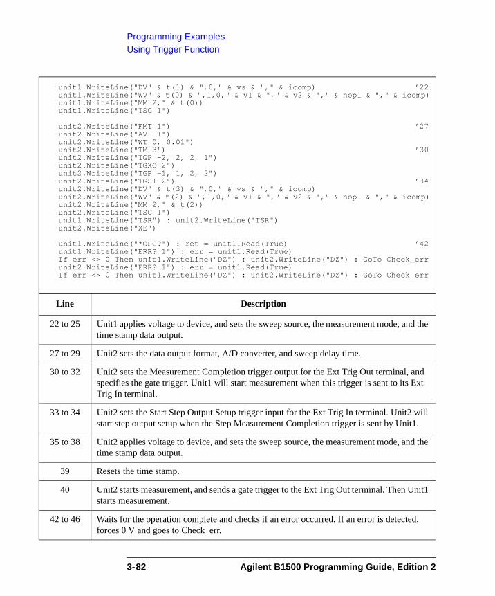
Programming ExamplesUsing Trigger Function
unit1.WriteLine("DV" & t(1) & ",0," & vs & "," & icomp) ’22unit1.WriteLine("WV" & t(0) & ",1,0," & v1 & "," & v2 & "," & nop1 & "," & icomp)unit1.WriteLine("MM 2," & t(0))unit1.WriteLine("TSC 1")
unit2.WriteLine("FMT 1") ’27unit2.WriteLine("AV -1")unit2.WriteLine("WT 0, 0.01")unit2.WriteLine("TM 3") ’30unit2.WriteLine("TGP -2, 2, 2, 1")unit2.WriteLine("TGXO 2")unit2.WriteLine("TGP -1, 1, 2, 2")unit2.WriteLine("TGSI 2") ’34unit2.WriteLine("DV" & t(3) & ",0," & vs & "," & icomp)unit2.WriteLine("WV" & t(2) & ",1,0," & v1 & "," & v2 & "," & nop1 & "," & icomp)unit2.WriteLine("MM 2," & t(2))unit2.WriteLine("TSC 1")unit1.WriteLine("TSR") : unit2.WriteLine("TSR")unit2.WriteLine("XE")
unit1.WriteLine("*OPC?") : ret = unit1.Read(True) ’42unit1.WriteLine("ERR? 1") : err = unit1.Read(True)If err <> 0 Then unit1.WriteLine("DZ") : unit2.WriteLine("DZ") : GoTo Check_errunit2.WriteLine("ERR? 1") : err = unit1.Read(True)If err <> 0 Then unit1.WriteLine("DZ") : unit2.WriteLine("DZ") : GoTo Check_err
Line Description
22 to 25 Unit1 applies voltage to device, and sets the sweep source, the measurement mode, and the time stamp data output.
27 to 29 Unit2 sets the data output format, A/D converter, and sweep delay time.
30 to 32 Unit2 sets the Measurement Completion trigger output for the Ext Trig Out terminal, and specifies the gate trigger. Unit1 will start measurement when this trigger is sent to its Ext Trig In terminal.
33 to 34 Unit2 sets the Start Step Output Setup trigger input for the Ext Trig In terminal. Unit2 will start step output setup when the Step Measurement Completion trigger is sent by Unit1.
35 to 38 Unit2 applies voltage to device, and sets the sweep source, the measurement mode, and the time stamp data output.
39 Resets the time stamp.
40 Unit2 starts measurement, and sends a gate trigger to the Ext Trig Out terminal. Then Unit1 starts measurement.
42 to 46 Waits for the operation complete and checks if an error occurred. If an error is detected, forces 0 V and goes to Check_err.
3-82 Agilent B1500 Programming Guide, Edition 2
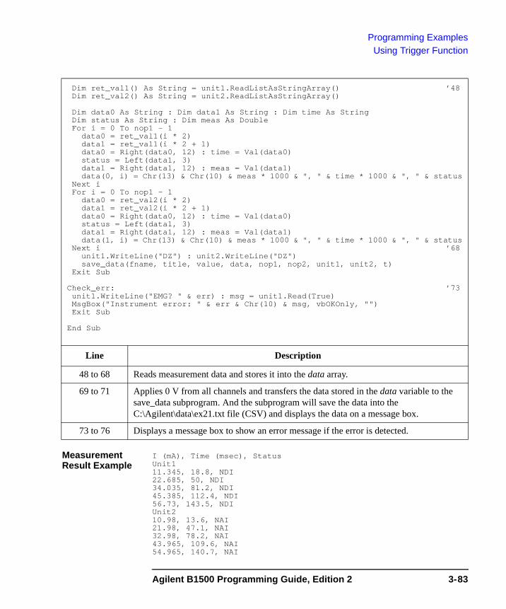
Programming ExamplesUsing Trigger Function
Measurement Result Example
I (mA), Time (msec), StatusUnit111.345, 18.8, NDI22.685, 50, NDI34.035, 81.2, NDI45.385, 112.4, NDI56.73, 143.5, NDIUnit210.98, 13.6, NAI21.98, 47.1, NAI32.98, 78.2, NAI43.965, 109.6, NAI54.965, 140.7, NAI
Dim ret_val1() As String = unit1.ReadListAsStringArray() ’48Dim ret_val2() As String = unit2.ReadListAsStringArray()
Dim data0 As String : Dim data1 As String : Dim time As StringDim status As String : Dim meas As DoubleFor i = 0 To nop1 - 1
data0 = ret_val1(i * 2)data1 = ret_val1(i * 2 + 1)data0 = Right(data0, 12) : time = Val(data0)status = Left(data1, 3)data1 = Right(data1, 12) : meas = Val(data1)data(0, i) = Chr(13) & Chr(10) & meas * 1000 & ", " & time * 1000 & ", " & status
Next iFor i = 0 To nop1 - 1
data0 = ret_val2(i * 2)data1 = ret_val2(i * 2 + 1)data0 = Right(data0, 12) : time = Val(data0)status = Left(data1, 3)data1 = Right(data1, 12) : meas = Val(data1)data(1, i) = Chr(13) & Chr(10) & meas * 1000 & ", " & time * 1000 & ", " & status
Next i ’68unit1.WriteLine("DZ") : unit2.WriteLine("DZ")save_data(fname, title, value, data, nop1, nop2, unit1, unit2, t)
Exit Sub
Check_err: ’73unit1.WriteLine("EMG? " & err) : msg = unit1.Read(True)MsgBox("Instrument error: " & err & Chr(10) & msg, vbOKOnly, "")Exit Sub
End Sub
Line Description
48 to 68 Reads measurement data and stores it into the data array.
69 to 71 Applies 0 V from all channels and transfers the data stored in the data variable to the save_data subprogram. And the subprogram will save the data into the C:\Agilent\data\ex21.txt file (CSV) and displays the data on a message box.
73 to 76 Displays a message box to show an error message if the error is detected.
Agilent B1500 Programming Guide, Edition 2 3-83
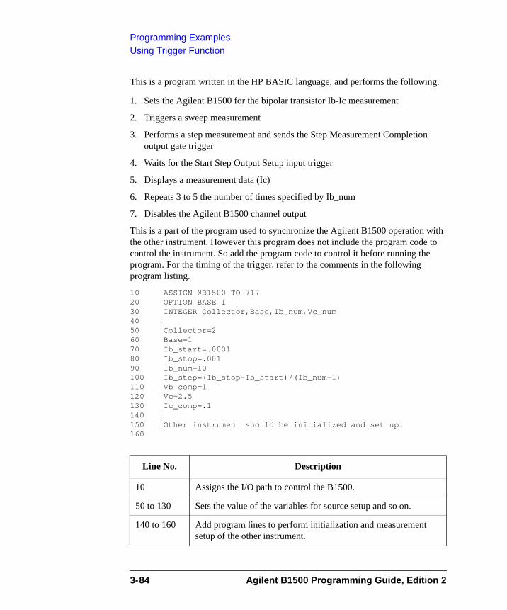
Programming ExamplesUsing Trigger Function
This is a program written in the HP BASIC language, and performs the following.
1. Sets the Agilent B1500 for the bipolar transistor Ib-Ic measurement
2. Triggers a sweep measurement
3. Performs a step measurement and sends the Step Measurement Completion output gate trigger
4. Waits for the Start Step Output Setup input trigger
5. Displays a measurement data (Ic)
6. Repeats 3 to 5 the number of times specified by Ib_num
7. Disables the Agilent B1500 channel output
This is a part of the program used to synchronize the Agilent B1500 operation with the other instrument. However this program does not include the program code to control the instrument. So add the program code to control it before running the program. For the timing of the trigger, refer to the comments in the following program listing.
10 ASSIGN @B1500 TO 71720 OPTION BASE 130 INTEGER Collector,Base,Ib_num,Vc_num40 !50 Collector=260 Base=170 Ib_start=.000180 Ib_stop=.00190 Ib_num=10100 Ib_step=(Ib_stop-Ib_start)/(Ib_num-1)110 Vb_comp=1120 Vc=2.5130 Ic_comp=.1140 !150 !Other instrument should be initialized and set up.160 !
Line No. Description
10 Assigns the I/O path to control the B1500.
50 to 130 Sets the value of the variables for source setup and so on.
140 to 160 Add program lines to perform initialization and measurement setup of the other instrument.
3-84 Agilent B1500 Programming Guide, Edition 2

Programming ExamplesUsing Trigger Function
170 OUTPUT @B1500;"FMT 5" ! ASCII w/header<,>180 OUTPUT @B1500;"AV -1" ! Averaging=1PLC190 OUTPUT @B1500;"WT 0,.01" ! Hold Time, Delay Time200 OUTPUT @B1500;"CN";Collector,Base210 OUTPUT @B1500;"TGP -2,2,2,3" ! StepMeasEndTrg Output220 OUTPUT @B1500;"TGMO 2" ! Gate Trigger230 OUTPUT @B1500;"TGP -1,1,2,2" ! StartStepSetupTrg Input240 OUTPUT @B1500;"TGSI 2" ! Ignore TRG for 1st step setup250 OUTPUT @B1500;"DV";Collector,0,Vc,Ic_comp260 OUTPUT @B1500;"WI";Base,1,0,Ib_start,Ib_stop,Ib_num,Vb_comp270 OUTPUT @B1500;"MM";2,Collector280 !290 !Other instrument must be set to the measurement ready and300 !trigger wait condition.310 !
Line No. Description
170 Specifies the data output format.
180 Sets the number of averaging samples of the ADC.
190 Sets the hold time and delay time.
200 Enables the source/measurement channels.
210 to 220 Sets the Step Measurement Completion trigger output for the Ext Trig Out terminal, and specifies the gate trigger.
230 to 240 Sets the Start Step Output Setup trigger input for the Ext Trig In terminal, also disables the input trigger for the first sweep step.
250 Forces voltage.
260 Sets the staircase sweep source.
270 Sets the measurement mode and the measurement channel.
280 to 310 To synchronize the Agilent B1500 operation with the operation of the other instrument, add program lines to set it to the measurement ready and trigger wait condition.
Agilent B1500 Programming Guide, Edition 2 3-85
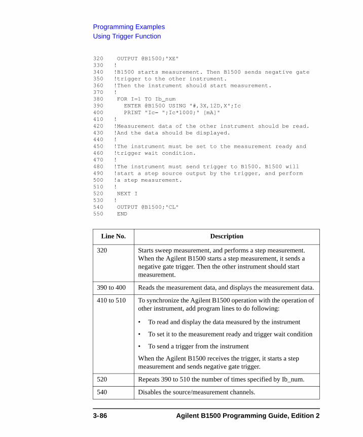
Programming ExamplesUsing Trigger Function
320 OUTPUT @B1500;"XE"330 !340 !B1500 starts measurement. Then B1500 sends negative gate350 !trigger to the other instrument.360 !Then the instrument should start measurement.370 !380 FOR I=1 TO Ib_num390 ENTER @B1500 USING "#,3X,12D,X";Ic400 PRINT "Ic= ";Ic*1000;" [mA]"410 !420 !Measurement data of the other instrument should be read.430 !And the data should be displayed.440 !450 !The instrument must be set to the measurement ready and460 !trigger wait condition.470 !480 !The instrument must send trigger to B1500. B1500 will 490 !start a step source output by the trigger, and perform500 !a step measurement.510 !520 NEXT I530 !540 OUTPUT @B1500;"CL"550 END
Line No. Description
320 Starts sweep measurement, and performs a step measurement. When the Agilent B1500 starts a step measurement, it sends a negative gate trigger. Then the other instrument should start measurement.
390 to 400 Reads the measurement data, and displays the measurement data.
410 to 510 To synchronize the Agilent B1500 operation with the operation of other instrument, add program lines to do following:
• To read and display the data measured by the instrument
• To set it to the measurement ready and trigger wait condition
• To send a trigger from the instrument
When the Agilent B1500 receives the trigger, it starts a step measurement and sends negative gate trigger.
520 Repeats 390 to 510 the number of times specified by Ib_num.
540 Disables the source/measurement channels.
3-86 Agilent B1500 Programming Guide, Edition 2
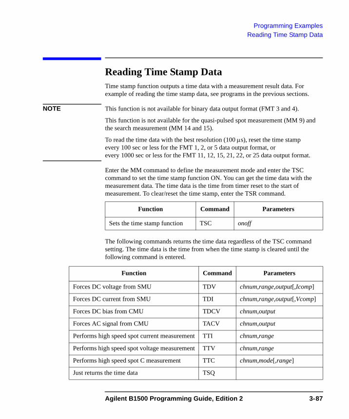
Programming ExamplesReading Time Stamp Data
Reading Time Stamp DataTime stamp function outputs a time data with a measurement result data. For example of reading the time stamp data, see programs in the previous sections.
NOTE This function is not available for binary data output format (FMT 3 and 4).
This function is not available for the quasi-pulsed spot measurement (MM 9) and the search measurement (MM 14 and 15).
To read the time data with the best resolution (100 μs), reset the time stamp every 100 sec or less for the FMT 1, 2, or 5 data output format, or every 1000 sec or less for the FMT 11, 12, 15, 21, 22, or 25 data output format.
Enter the MM command to define the measurement mode and enter the TSC command to set the time stamp function ON. You can get the time data with the measurement data. The time data is the time from timer reset to the start of measurement. To clear/reset the time stamp, enter the TSR command.
The following commands returns the time data regardless of the TSC command setting. The time data is the time from when the time stamp is cleared until the following command is entered.
Function Command Parameters
Sets the time stamp function TSC onoff
Function Command Parameters
Forces DC voltage from SMU TDV chnum,range,output[,Icomp]
Forces DC current from SMU TDI chnum,range,output[,Vcomp]
Forces DC bias from CMU TDCV chnum,output
Forces AC signal from CMU TACV chnum,output
Performs high speed spot current measurement TTI chnum,range
Performs high speed spot voltage measurement TTV chnum,range
Performs high speed spot C measurement TTC chnum,mode[,range]
Just returns the time data TSQ
Agilent B1500 Programming Guide, Edition 2 3-87
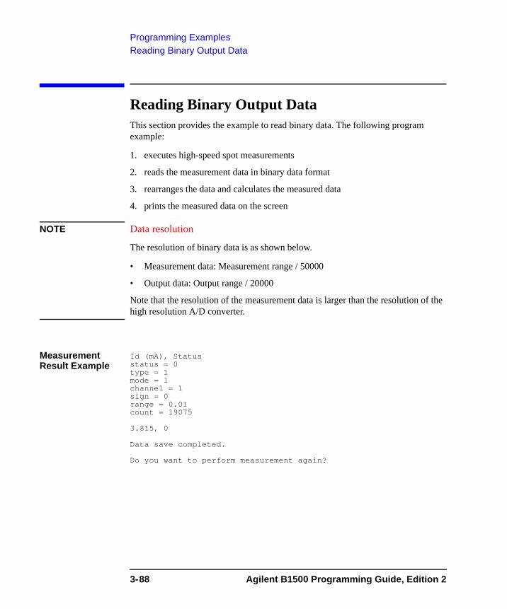
Programming ExamplesReading Binary Output Data
Reading Binary Output Data This section provides the example to read binary data. The following program example:
1. executes high-speed spot measurements
2. reads the measurement data in binary data format
3. rearranges the data and calculates the measured data
4. prints the measured data on the screen
NOTE Data resolution
The resolution of binary data is as shown below.
• Measurement data: Measurement range / 50000
• Output data: Output range / 20000
Note that the resolution of the measurement data is larger than the resolution of the high resolution A/D converter.
Measurement Result Example
Id (mA), Statusstatus = 0type = 1mode = 1channel = 1sign = 0range = 0.01count = 19075
3.815, 0
Data save completed.
Do you want to perform measurement again?
3-88 Agilent B1500 Programming Guide, Edition 2
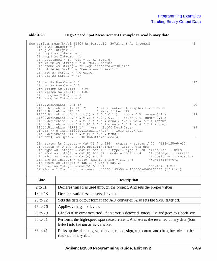
Programming ExamplesReading Binary Output Data
Table 3-23 High-Speed Spot Measurement Example to read binary data
Sub perform_meas(ByVal B1500 As DirectIO, ByVal t() As Integer) ’1Dim i As Integer = 0Dim j As Integer = 0Dim nop1 As Integer = 1Dim nop2 As Integer = 1Dim data(nop2 - 1, nop1 - 1) As StringDim value As String = "Id (mA), Status"Dim fname As String = "C:\Agilent\data\ex30.txt"Dim title As String = "Measurement Result"Dim msg As String = "No error."Dim err As String = "0"
Dim vd As Double = 0.5 ’13Dim vg As Double = 0.5Dim idcomp As Double = 0.05Dim igcomp As Double = 0.01Dim orng As Integer = 0Dim mrng As Integer = 0
B1500.WriteLine("FMT 3") ’20B1500.WriteLine("AV 10,1") ’ sets number of samples for 1 dataB1500.WriteLine("FL 0") ’ sets filter offB1500.WriteLine("DV " & t(3) & ",0,0,0.1") ’out= 0 V, comp= 0.1 A ’23B1500.WriteLine("DV " & t(2) & ",0,0,0.1") ’out= 0 V, comp= 0.1 AB1500.WriteLine("DV " & t(1) & "," & orng & "," & vg & "," & igcomp)B1500.WriteLine("DV " & t(0) & "," & orng & "," & vd & "," & idcomp)B1500.WriteLine("ERR? 1") : err = B1500.Read(True) ’28If err <> 0 Then B1500.WriteLine("DZ") : GoTo Check_errB1500.WriteLine("TI " & t(0) & "," & mrng)Dim dat() As Byte = B1500.UnbufferedRead(4) ’31
Dim status As Integer = dat(3) And 224 : status = status / 32 ’224=128+64+32If status <> 0 Then B1500.WriteLine("DZ") : GoTo Check_errDim type As Integer = dat(0) And 128 : type = type / 128 ’0:source, 1:measDim mode As Integer = dat(0) And 64 : mode = mode / 64 ’0:voltage, 1:currentDim sign As Integer = dat(0) And 1 ’0:positive, 1:negativeDim rng As Integer = dat(0) And 62 : rng = rng / 2 ’62=32+16+8+4+2Dim count As Integer = dat(1) * 256 + dat(2)Dim chan As Integer = dat(3) And 31 ’31=16+8+4+2+1If sign = 1 Then count = count - 65536 ’65536 = 10000000000000000 (17 bits)
Line Description
2 to 11 Declares variables used through the project. And sets the proper values.13 to 18 Declares variables and sets the value.20 to 22 Sets the data output format and A/D converter. Also sets the SMU filter off.23 to 26 Applies voltage to device.28 to 29 Checks if an error occurred. If an error is detected, forces 0 V and goes to Check_err.30 to 31 Performs the high-speed spot measurement. And stores the returned binary data (four
bytes) into the dat array variable.33 to 41 Picks up the elements, status, type, mode, sign, rng, count, and chan, included in the
returned binary data.
Agilent B1500 Programming Guide, Edition 2 3-89

Programming ExamplesReading Binary Output Data
Dim range As Double ’43If mode = 1 Then ’ current range
range = 10 ^ (rng - 20)If rng = 20 Then
B1500.WriteLine("UNT? 1")Dim unt As String = B1500.ReadDim mdl(8) As String : Dim c As StringDim a As Integer : Dim b As Integer = 0 : Dim d As Integer = 0For a = 1 To Len(unt)c = Mid(unt, a, 1)If c = "," Then mdl(d) = Mid(unt, b + 1, a - b - 1) : d = d + 1If c = ";" Then b = a
NextIf mdl(chan) = "E5291A" Then range = 0.2
End IfElse ’ voltage range
If rng = 8 Then range = 0.5If rng = 9 Then range = 5If rng = 11 Then range = 2If rng = 12 Then range = 20If rng = 13 Then range = 40If rng = 14 Then range = 100If rng = 15 Then range = 200
End If ’66
’value = value & Chr(13) & Chr(10) & "status = " & status ’68’value = value & Chr(13) & Chr(10) & "type = " & type’value = value & Chr(13) & Chr(10) & "mode = " & mode’value = value & Chr(13) & Chr(10) & "channel = " & chan’value = value & Chr(13) & Chr(10) & "sign = " & sign’value = value & Chr(13) & Chr(10) & "range = " & range’value = value & Chr(13) & Chr(10) & "count = " & count & Chr(13) & Chr(10)
Dim meas As Double ’76If type = 0 Then meas = count * range / 20000 ’source dataIf type = 1 Then meas = count * range / 50000 ’measurement data
data(j, i) = Chr(13) & Chr(10) & meas * 1000 & ", " & status ’80
B1500.WriteLine("DZ") ’82save_data(fname, title, value, data, nop1, nop2, B1500, t)Exit Sub
Check_err: ’86B1500.WriteLine("EMG? " & err) : msg = B1500.Read(True)MsgBox("Instrument error: " & err & Chr(10) & msg, vbOKOnly, "")Exit Sub
End Sub
Line Description
43 to 66 Checks the measurement range or output range setting.68 to 74 If you want to display and save the binary data elements, delete ’ at the top of the lines.76 to 80 Calculates the measurement data or source output data. And, stores the data into the
data array. 82 to 84 Applies 0 V from all channels. And transfers the data stored in the data variable to the
save_data subprogram (see Table 3-1). And the subprogram will save the data into the C:\Agilent\data\ex30.txt file (CSV) and displays the data on a message box.
86 to 89 Displays a message box to show an error message if the error is detected.
3-90 Agilent B1500 Programming Guide, Edition 2
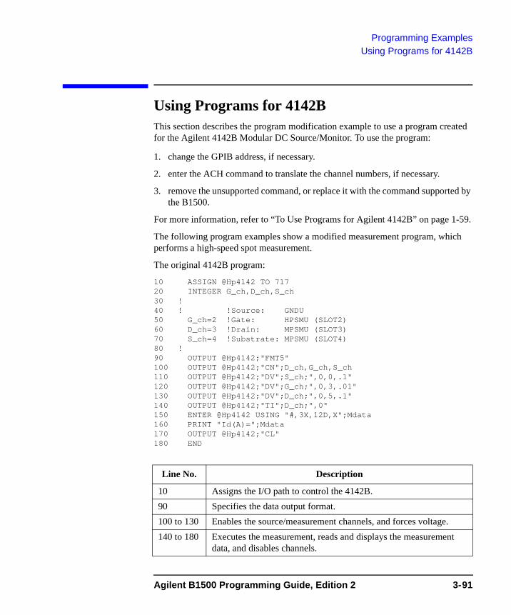
Programming ExamplesUsing Programs for 4142B
Using Programs for 4142BThis section describes the program modification example to use a program created for the Agilent 4142B Modular DC Source/Monitor. To use the program:
1. change the GPIB address, if necessary.
2. enter the ACH command to translate the channel numbers, if necessary.
3. remove the unsupported command, or replace it with the command supported by the B1500.
For more information, refer to “To Use Programs for Agilent 4142B” on page 1-59.
The following program examples show a modified measurement program, which performs a high-speed spot measurement.
The original 4142B program:
10 ASSIGN @Hp4142 TO 71720 INTEGER G_ch,D_ch,S_ch30 !40 ! !Source: GNDU50 G_ch=2 !Gate: HPSMU (SLOT2)60 D_ch=3 !Drain: MPSMU (SLOT3)70 S_ch=4 !Substrate: MPSMU (SLOT4)80 !90 OUTPUT @Hp4142;"FMT5"100 OUTPUT @Hp4142;"CN";D_ch,G_ch,S_ch110 OUTPUT @Hp4142;"DV";S_ch;",0,0,.1"120 OUTPUT @Hp4142;"DV";G_ch;",0,3,.01"130 OUTPUT @Hp4142;"DV";D_ch;",0,5,.1"140 OUTPUT @Hp4142;"TI";D_ch;",0"150 ENTER @Hp4142 USING "#,3X,12D,X";Mdata160 PRINT "Id(A)=";Mdata170 OUTPUT @Hp4142;"CL"180 END
Line No. Description
10 Assigns the I/O path to control the 4142B.90 Specifies the data output format.100 to 130 Enables the source/measurement channels, and forces voltage.140 to 180 Executes the measurement, reads and displays the measurement
data, and disables channels.
Agilent B1500 Programming Guide, Edition 2 3-91
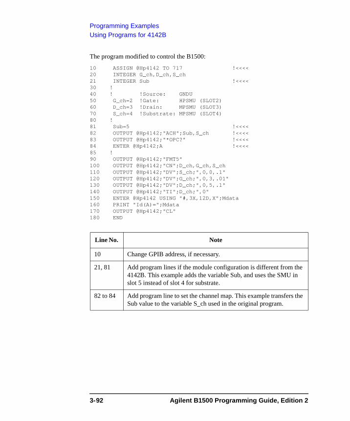
Programming ExamplesUsing Programs for 4142B
The program modified to control the B1500:
10 ASSIGN @Hp4142 TO 717 !<<<<20 INTEGER G_ch,D_ch,S_ch21 INTEGER Sub !<<<<30 !40 ! !Source: GNDU50 G_ch=2 !Gate: HPSMU (SLOT2)60 D_ch=3 !Drain: MPSMU (SLOT3)70 S_ch=4 !Substrate: MPSMU (SLOT4)80 !81 Sub=5 !<<<<82 OUTPUT @Hp4142;"ACH";Sub,S_ch !<<<<83 OUTPUT @Hp4142;"*OPC?" !<<<<84 ENTER @Hp4142;A !<<<<85 !90 OUTPUT @Hp4142;"FMT5"100 OUTPUT @Hp4142;"CN";D_ch,G_ch,S_ch110 OUTPUT @Hp4142;"DV";S_ch;",0,0,.1"120 OUTPUT @Hp4142;"DV";G_ch;",0,3,.01"130 OUTPUT @Hp4142;"DV";D_ch;",0,5,.1"140 OUTPUT @Hp4142;"TI";D_ch;",0"150 ENTER @Hp4142 USING "#,3X,12D,X";Mdata160 PRINT "Id(A)=";Mdata170 OUTPUT @Hp4142;"CL"180 END
Line No. Note
10 Change GPIB address, if necessary.
21, 81 Add program lines if the module configuration is different from the 4142B. This example adds the variable Sub, and uses the SMU in slot 5 instead of slot 4 for substrate.
82 to 84 Add program line to set the channel map. This example transfers the Sub value to the variable S_ch used in the original program.
3-92 Agilent B1500 Programming Guide, Edition 2
Programming ExamplesUsing Programs for 4155B/4156B/4155C/4156C
Using Programs for 4155B/4156B/4155C/4156CThis section describes the program modification example to use a FLEX command program created for the Agilent 4155B/4156B/4155C/4156C Parameter Analyzer. To use the program:
1. change the GPIB address, if necessary.
2. enter the ACH command to translate the channel numbers, if necessary.
3. change the FMT command parameter value to use the data output format compatible with the 4155/4156 output data, or change the program lines to read the measurement data.
4. remove the US command.
5. remove the RMD? command.
6. remove the unsupported command, or replace the command with the corresponding command supported by the B1500.
For more information, refer to “To Use Programs for Agilent 4155/4156” on page 1-60.
The following program examples show a modified measurement program, which performs a high-speed spot measurement.
Agilent B1500 Programming Guide, Edition 2 3-93
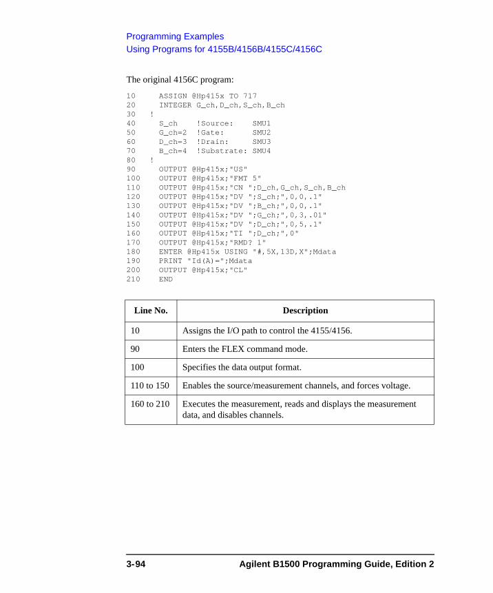
Programming ExamplesUsing Programs for 4155B/4156B/4155C/4156C
The original 4156C program:
10 ASSIGN @Hp415x TO 71720 INTEGER G_ch,D_ch,S_ch,B_ch30 !40 S_ch !Source: SMU150 G_ch=2 !Gate: SMU260 D_ch=3 !Drain: SMU370 B_ch=4 !Substrate: SMU480 !90 OUTPUT @Hp415x;"US"100 OUTPUT @Hp415x;"FMT 5"110 OUTPUT @Hp415x;"CN ";D_ch,G_ch,S_ch,B_ch120 OUTPUT @Hp415x;"DV ";S_ch;",0,0,.1"130 OUTPUT @Hp415x;"DV ";B_ch;",0,0,.1"140 OUTPUT @Hp415x;"DV ";G_ch;",0,3,.01"150 OUTPUT @Hp415x;"DV ";D_ch;",0,5,.1"160 OUTPUT @Hp415x;"TI ";D_ch;",0"170 OUTPUT @Hp415x;"RMD? 1"180 ENTER @Hp415x USING "#,5X,13D,X";Mdata190 PRINT "Id(A)=";Mdata200 OUTPUT @Hp415x;"CL"210 END
Line No. Description
10 Assigns the I/O path to control the 4155/4156.
90 Enters the FLEX command mode.
100 Specifies the data output format.
110 to 150 Enables the source/measurement channels, and forces voltage.
160 to 210 Executes the measurement, reads and displays the measurement data, and disables channels.
3-94 Agilent B1500 Programming Guide, Edition 2
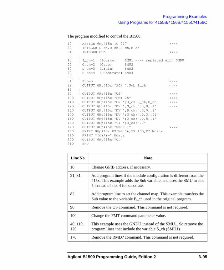
Programming ExamplesUsing Programs for 4155B/4156B/4155C/4156C
The program modified to control the B1500:
10 ASSIGN @Hp415x TO 717 !<<<<20 INTEGER G_ch,D_ch,S_ch,B_ch21 INTEGER Sub !<<<<30 !40 ! S_ch=1 !Source: SMU1 <<<< replaced with GNDU50 G_ch=2 !Gate: SMU260 D_ch=3 !Drain: SMU370 B_ch=4 !Substrate: SMU480 !81 Sub=5 !<<<<82 OUTPUT @Hp415x;"ACH ";Sub,B_ch !<<<<83 !90 ! OUTPUT @Hp415x;"US" <<<<100 OUTPUT @Hp415x;"FMT 25" !<<<<110 OUTPUT @Hp415x;"CN ";D_ch,G_ch,B_ch !<<<<120 ! OUTPUT @Hp415x;"DV ";S_ch;",0,0,.1" <<<<130 OUTPUT @Hp415x;"DV ";B_ch;",0,0,.1"140 OUTPUT @Hp415x;"DV ";G_ch;",0,3,.01"150 OUTPUT @Hp415x;"DV ";D_ch;",0,5,.1"160 OUTPUT @Hp415x;"TI ";D_ch;",0"170 ! OUTPUT @Hp415x;"RMD? 1" <<<<180 ENTER @Hp415x USING "#,5X,13D,X";Mdata190 PRINT "Id(A)=";Mdata200 OUTPUT @Hp415x;"CL"210 END
Line No. Note
10 Change GPIB address, if necessary.
21, 81 Add program lines if the module configuration is different from the 415x. This example adds the Sub variable, and uses the SMU in slot 5 instead of slot 4 for substrate.
82 Add program line to set the channel map. This example transfers the Sub value to the variable B_ch used in the original program.
90 Remove the US command. This command is not required.
100 Change the FMT command parameter value.
40, 110, 120
This example uses the GNDU instead of the SMU1. So remove the program lines that include the variable S_ch (SMU1).
170 Remove the RMD? command. This command is not required.
Agilent B1500 Programming Guide, Edition 2 3-95

Programming ExamplesUsing Programs for 4155B/4156B/4155C/4156C
3-96 Agilent B1500 Programming Guide, Edition 2
4 Command Reference
Command Reference
This chapter is the complete reference of the GPIB commands of the Agilent B1500:
• “Command Summary”
• “Command Parameters”
• “Command Reference”
NOTE Module model number and description
In this chapter, plug-in modules and accessory for the Agilent B1500 will be expressed by the model number or the following abbreviation as shown below.
B1510A: HPSMU (high power SMU)
B1511A: MPSMU (medium power SMU)
B1517A: HRSMU (high resolution SMU)
E5288A: ASU (atto sense and switch unit)
B1520A: MFCMU (multi frequency capacitance measurement unit)
N1301A: SCUU (SMU CMU unify unit)
4-2 Agilent B1500 Programming Guide, Edition 2
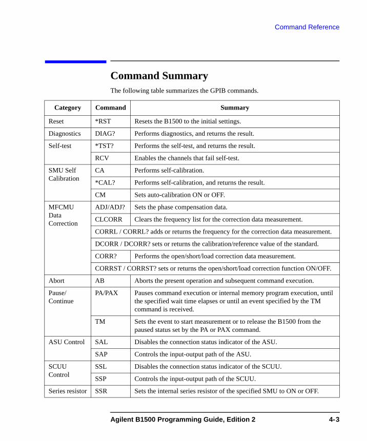
Command Reference
Command SummaryThe following table summarizes the GPIB commands.
Category Command Summary
Reset *RST Resets the B1500 to the initial settings.
Diagnostics DIAG? Performs diagnostics, and returns the result.
Self-test *TST? Performs the self-test, and returns the result.
RCV Enables the channels that fail self-test.
SMU Self Calibration
CA Performs self-calibration.
*CAL? Performs self-calibration, and returns the result.
CM Sets auto-calibration ON or OFF.
MFCMU Data Correction
ADJ/ADJ? Sets the phase compensation data.
CLCORR Clears the frequency list for the correction data measurement.
CORRL / CORRL? adds or returns the frequency for the correction data measurement.
DCORR / DCORR? sets or returns the calibration/reference value of the standard.
CORR? Performs the open/short/load correction data measurement.
CORRST / CORRST? sets or returns the open/short/load correction function ON/OFF.
Abort AB Aborts the present operation and subsequent command execution.
Pause/ Continue
PA/PAX Pauses command execution or internal memory program execution, until the specified wait time elapses or until an event specified by the TM command is received.
TM Sets the event to start measurement or to release the B1500 from the paused status set by the PA or PAX command.
ASU Control SAL Disables the connection status indicator of the ASU.
SAP Controls the input-output path of the ASU.
SCUU Control
SSL Disables the connection status indicator of the SCUU.
SSP Controls the input-output path of the SCUU.
Series resistor SSR Sets the internal series resistor of the specified SMU to ON or OFF.
Agilent B1500 Programming Guide, Edition 2 4-3
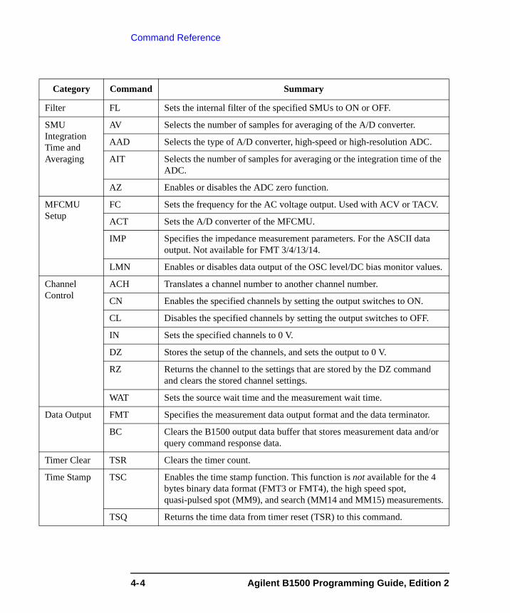
Command Reference
Filter FL Sets the internal filter of the specified SMUs to ON or OFF.
SMU Integration Time and Averaging
AV Selects the number of samples for averaging of the A/D converter.
AAD Selects the type of A/D converter, high-speed or high-resolution ADC.
AIT Selects the number of samples for averaging or the integration time of the ADC.
AZ Enables or disables the ADC zero function.
MFCMU Setup
FC Sets the frequency for the AC voltage output. Used with ACV or TACV.
ACT Sets the A/D converter of the MFCMU.
IMP Specifies the impedance measurement parameters. For the ASCII data output. Not available for FMT 3/4/13/14.
LMN Enables or disables data output of the OSC level/DC bias monitor values.
Channel Control
ACH Translates a channel number to another channel number.
CN Enables the specified channels by setting the output switches to ON.
CL Disables the specified channels by setting the output switches to OFF.
IN Sets the specified channels to 0 V.
DZ Stores the setup of the channels, and sets the output to 0 V.
RZ Returns the channel to the settings that are stored by the DZ command and clears the stored channel settings.
WAT Sets the source wait time and the measurement wait time.
Data Output FMT Specifies the measurement data output format and the data terminator.
BC Clears the B1500 output data buffer that stores measurement data and/or query command response data.
Timer Clear TSR Clears the timer count.
Time Stamp TSC Enables the time stamp function. This function is not available for the 4 bytes binary data format (FMT3 or FMT4), the high speed spot, quasi-pulsed spot (MM9), and search (MM14 and MM15) measurements.
TSQ Returns the time data from timer reset (TSR) to this command.
Category Command Summary
4-4 Agilent B1500 Programming Guide, Edition 2
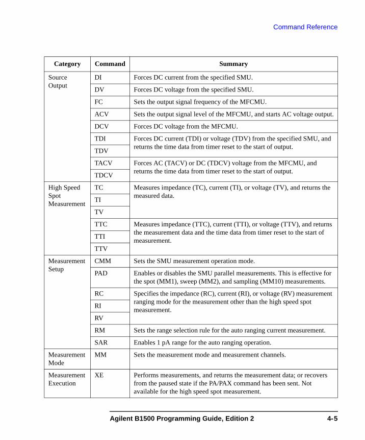
Command Reference
Source Output
DI Forces DC current from the specified SMU.
DV Forces DC voltage from the specified SMU.
FC Sets the output signal frequency of the MFCMU.
ACV Sets the output signal level of the MFCMU, and starts AC voltage output.
DCV Forces DC voltage from the MFCMU.
TDI Forces DC current (TDI) or voltage (TDV) from the specified SMU, and returns the time data from timer reset to the start of output. TDV
TACV Forces AC (TACV) or DC (TDCV) voltage from the MFCMU, and returns the time data from timer reset to the start of output.TDCV
High Speed Spot Measurement
TC Measures impedance (TC), current (TI), or voltage (TV), and returns the measured data.TI
TV
TTC Measures impedance (TTC), current (TTI), or voltage (TTV), and returns the measurement data and the time data from timer reset to the start of measurement.TTI
TTV
Measurement Setup
CMM Sets the SMU measurement operation mode.
PAD Enables or disables the SMU parallel measurements. This is effective for the spot (MM1), sweep (MM2), and sampling (MM10) measurements.
RC Specifies the impedance (RC), current (RI), or voltage (RV) measurement ranging mode for the measurement other than the high speed spot measurement.RI
RV
RM Sets the range selection rule for the auto ranging current measurement.
SAR Enables 1 pA range for the auto ranging operation.
Measurement Mode
MM Sets the measurement mode and measurement channels.
Measurement Execution
XE Performs measurements, and returns the measurement data; or recovers from the paused state if the PA/PAX command has been sent. Not available for the high speed spot measurement.
Category Command Summary
Agilent B1500 Programming Guide, Edition 2 4-5
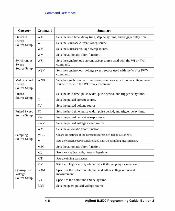
Command Reference
Staircase Sweep Source Setup
WT Sets the hold time, delay time, step delay time, and trigger delay time.
WI Sets the staircase current sweep source.
WV Sets the staircase voltage sweep source.
WM Sets the automatic abort function.
Synchronous Sweep Source Setup
WSI Sets the synchronous current sweep source used with the WI or PWI command.
WSV Sets the synchronous voltage sweep source used with the WV or PWV command.
Multi channel Sweep Source Setup
WNX Sets the synchronous current sweep source or synchronous voltage sweep source used with the WI or WV command.
Pulsed Source Setup
PT Sets the hold time, pulse width, pulse period, and trigger delay time.
PI Sets the pulsed current source.
PV Sets the pulsed voltage source.
Pulsed Sweep Source Setup
PT Sets the hold time, pulse width, pulse period, and trigger delay time.
PWI Sets the pulsed current sweep source.
PWV Sets the pulsed voltage sweep source.
WM Sets the automatic abort function.
Sampling Source Setup
MCC Clears the settings of the constant sources defined by MI or MV.
MI Sets the current source synchronized with the sampling measurement.
MSC Sets the automatic abort function.
ML Sets the sampling mode, linear or logarithm.
MT Sets the timing parameters.
MV Sets the voltage source synchronized with the sampling measurement.
Quasi-pulsed Voltage Source Setup
BDM Specifies the detection interval, and either voltage or current measurement.
BDT Specifies the hold time and delay time.
BDV Sets the quasi-pulsed voltage source.
Category Command Summary
4-6 Agilent B1500 Programming Guide, Edition 2

Command Reference
Binary Search Measurement Setup
BSM Sets the source output control mode and the automatic abort function.
BST Specifies the hold time and delay time.
BSVM Selects the data output mode.
BSI Sets the current source channel.
BSSI Sets the synchronous current source channel.
BGV Sets the voltage monitor channel.
BSV Sets the voltage source channel.
BSSV Sets the synchronous voltage source channel.
BGI Sets the current monitor channel.
Linear Search Measurement Setup
LSTM Specifies the hold time and delay time.
LSVM Selects the data output mode.
LSI Sets the current source channel.
LSSI Sets the synchronous current source channel.
LGV Sets the voltage monitor channel.
LSV Sets the voltage source channel.
LSSV Sets the synchronous voltage source channel.
LGI Sets the current monitor channel.
LSM Sets the automatic abort function.
CV Sweep Source Setup
WDCV Sets the DC bias sweep source for the CV sweep measurement.
WMDCV Sets the automatic abort function, also sets the post sweep condition.
WTDCV Sets the hold time, delay time, step delay time, and trigger delay time.
Digital I/O port
ERM Changes the digital I/O port assignments.
ERS? Returns the digital I/O port status.
ERC Changes the output status of the digital I/O port.
Category Command Summary
Agilent B1500 Programming Guide, Edition 2 4-7
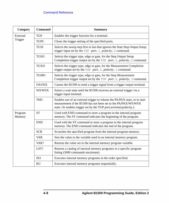
Command Reference
External Trigger
TGP Enables the trigger function for a terminal.
TGPC Clears the trigger setting of the specified ports.
TGSI Selects the sweep step first or last that ignores the Start Step Output Setup trigger input set by the TGP port,1,polarity,2 command.
TGSO Selects the trigger type, edge or gate, for the Step Output Setup Completion trigger output set by the TGP port,2,polarity,2 command.
TGXO Selects the trigger type, edge or gate, for the Measurement Completion trigger output set by the TGP port,2,polarity,1 command.
TGMO Selects the trigger type, edge or gate, for the Step Measurement Completion trigger output set by the TGP port,2,polarity,3 command.
OS/OSX Causes the B1500 to send a trigger signal from a trigger output terminal.
WS/WSX Enters a wait state until the B1500 receives an external trigger via a trigger input terminal.
TM3 Enables use of an external trigger to release the PA/PAX state, or to start measurement if the B1500 has not been set to the PA/PAX/WS/WSX state. Or enables trigger set by the TGP port,terminal,polarity,1.
Program Memory
ST Used with END command to store a program in the internal program memory. The ST command indicates the beginning of the program.
END Used with the ST command to store a program in the internal program memory. The END command indicates the end of the program.
SCR Scratches the specified program from the internal program memory.
VAR Sets the value to the variable used in an internal memory program.
VAR? Returns the value set to the internal memory program variable.
LST? Returns a catalog of internal memory programs or a specific program listing (3000 commands maximum).
DO Executes internal memory programs in the order specified.
RU Executes internal memory programs sequentially.
Category Command Summary
4-8 Agilent B1500 Programming Guide, Edition 2

Command Reference
Query ERR? Returns error codes.
EMG? Returns error message for the specified error code.
*IDN? Returns the instrument model number and the ROM version number.
LOP? Returns the operation status of all modules.
*LRN? Returns channel settings or the B1500 command parameter settings.
NUB? Returns the number of measurement data items in the output data buffer.
*OPC? Starts to monitor pending operations, or asks the OPC bit setting.
UNT? Returns the model and revision numbers of all modules.
WNU? Returns the number of sweep steps specified by the sweep command.
WZ? Returns 0 if all channel output is ± 2 V or less, or 1 if any channel applies more than ± 2 V.
Status Byte *SRE Enables the specified bits of the status byte register.
*SRE? Returns which bits of the status byte register are enabled.
*STB? Returns the status byte setting.
Category Command Summary
Agilent B1500 Programming Guide, Edition 2 4-9
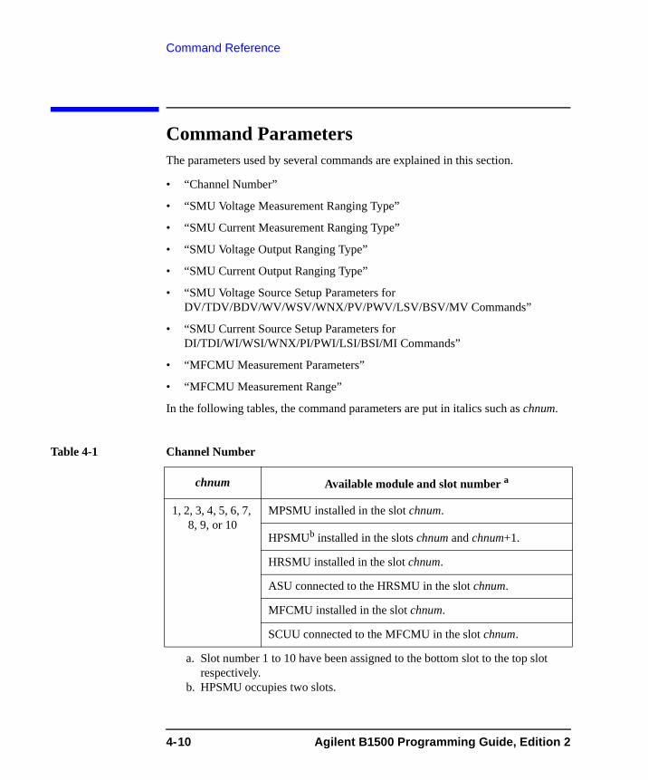
Command Reference
Command ParametersThe parameters used by several commands are explained in this section.
• “Channel Number”
• “SMU Voltage Measurement Ranging Type”
• “SMU Current Measurement Ranging Type”
• “SMU Voltage Output Ranging Type”
• “SMU Current Output Ranging Type”
• “SMU Voltage Source Setup Parameters for DV/TDV/BDV/WV/WSV/WNX/PV/PWV/LSV/BSV/MV Commands”
• “SMU Current Source Setup Parameters for DI/TDI/WI/WSI/WNX/PI/PWI/LSI/BSI/MI Commands”
• “MFCMU Measurement Parameters”
• “MFCMU Measurement Range”
In the following tables, the command parameters are put in italics such as chnum.
Table 4-1 Channel Number
chnum Available module and slot number a
a. Slot number 1 to 10 have been assigned to the bottom slot to the top slot respectively.
1, 2, 3, 4, 5, 6, 7, 8, 9, or 10
MPSMU installed in the slot chnum.
HPSMUb installed in the slots chnum and chnum+1.
b. HPSMU occupies two slots.
HRSMU installed in the slot chnum.
ASU connected to the HRSMU in the slot chnum.
MFCMU installed in the slot chnum.
SCUU connected to the MFCMU in the slot chnum.
4-10 Agilent B1500 Programming Guide, Edition 2
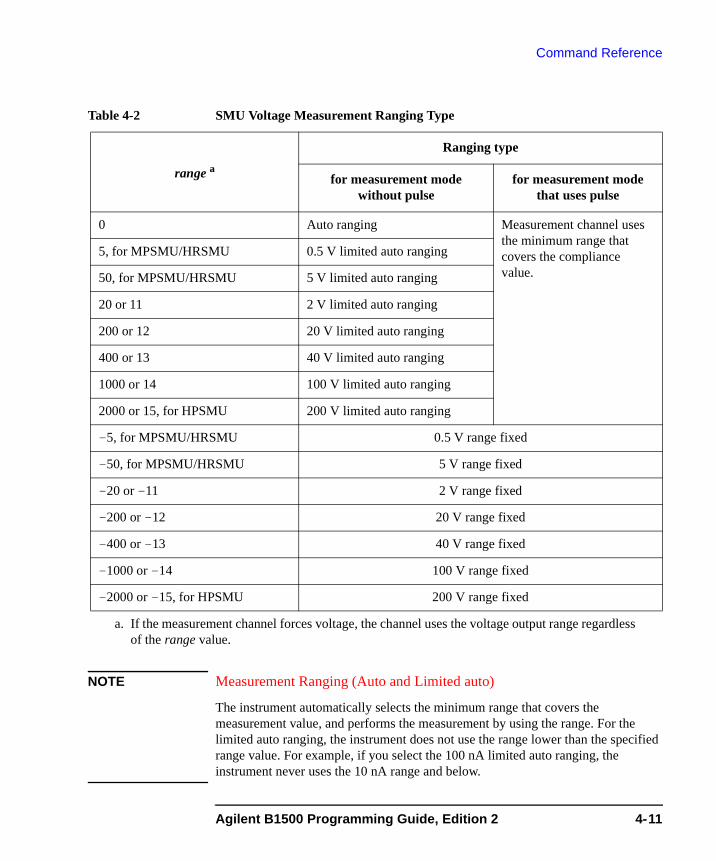
Command Reference
Table 4-2 SMU Voltage Measurement Ranging Type
NOTE Measurement Ranging (Auto and Limited auto)
The instrument automatically selects the minimum range that covers the measurement value, and performs the measurement by using the range. For the limited auto ranging, the instrument does not use the range lower than the specified range value. For example, if you select the 100 nA limited auto ranging, the instrument never uses the 10 nA range and below.
range a
a. If the measurement channel forces voltage, the channel uses the voltage output range regardless of the range value.
Ranging type
for measurement mode without pulse
for measurement mode that uses pulse
0 Auto ranging Measurement channel uses the minimum range that covers the compliance value.
5, for MPSMU/HRSMU 0.5 V limited auto ranging
50, for MPSMU/HRSMU 5 V limited auto ranging
20 or 11 2 V limited auto ranging
200 or 12 20 V limited auto ranging
400 or 13 40 V limited auto ranging
1000 or 14 100 V limited auto ranging
2000 or 15, for HPSMU 200 V limited auto ranging
-5, for MPSMU/HRSMU 0.5 V range fixed
-50, for MPSMU/HRSMU 5 V range fixed
-20 or -11 2 V range fixed
-200 or -12 20 V range fixed
-400 or -13 40 V range fixed
-1000 or -14 100 V range fixed
-2000 or -15, for HPSMU 200 V range fixed
Agilent B1500 Programming Guide, Edition 2 4-11

Command Reference
Table 4-3 SMU Current Measurement Ranging Type
range a
a. If the measurement channel forces current, the channel uses the current output range regardless of the range value.
Ranging type
for measurement mode without pulse
for measurement mode that uses pulse
0 Auto ranging Measurement channel uses the minimum range that covers the compliance value.
8, for HRSMU+ASU 1 pA limited auto ranging9, for HRSMU 10 pA limited auto ranging10, for HRSMU 100 pA limited auto ranging11 1 nA limited auto ranging12 10 nA limited auto ranging13 100 nA limited auto ranging14 1 μA limited auto ranging15 10 μA limited auto ranging16 100 μA limited auto ranging17 1 mA limited auto ranging18 10 mA limited auto ranging19 100 mA limited auto ranging20, for HPSMU 1 A limited auto ranging-8, for HRSMU+ASU 1 pA range fixed-9, for HRSMU 10 pA range fixed-10, for HRSMU 100 pA range fixed-11 1 nA range fixed-12 10 nA range fixed-13 100 nA range fixed-14 1 μA range fixed-15 10 μA range fixed-16 100 μA range fixed-17 1 mA range fixed-18 10 mA range fixed-19 100 mA range fixed-20, for HPSMU 1 A range fixed
4-12 Agilent B1500 Programming Guide, Edition 2
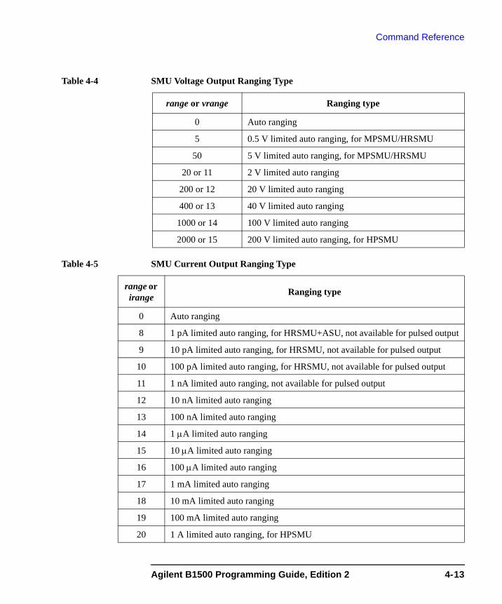
Command Reference
Table 4-4 SMU Voltage Output Ranging Type
Table 4-5 SMU Current Output Ranging Type
range or vrange Ranging type
0 Auto ranging
5 0.5 V limited auto ranging, for MPSMU/HRSMU
50 5 V limited auto ranging, for MPSMU/HRSMU
20 or 11 2 V limited auto ranging
200 or 12 20 V limited auto ranging
400 or 13 40 V limited auto ranging
1000 or 14 100 V limited auto ranging
2000 or 15 200 V limited auto ranging, for HPSMU
range or irange Ranging type
0 Auto ranging
8 1 pA limited auto ranging, for HRSMU+ASU, not available for pulsed output
9 10 pA limited auto ranging, for HRSMU, not available for pulsed output
10 100 pA limited auto ranging, for HRSMU, not available for pulsed output
11 1 nA limited auto ranging, not available for pulsed output
12 10 nA limited auto ranging
13 100 nA limited auto ranging
14 1 μA limited auto ranging
15 10 μA limited auto ranging
16 100 μA limited auto ranging
17 1 mA limited auto ranging
18 10 mA limited auto ranging
19 100 mA limited auto ranging
20 1 A limited auto ranging, for HPSMU
Agilent B1500 Programming Guide, Edition 2 4-13
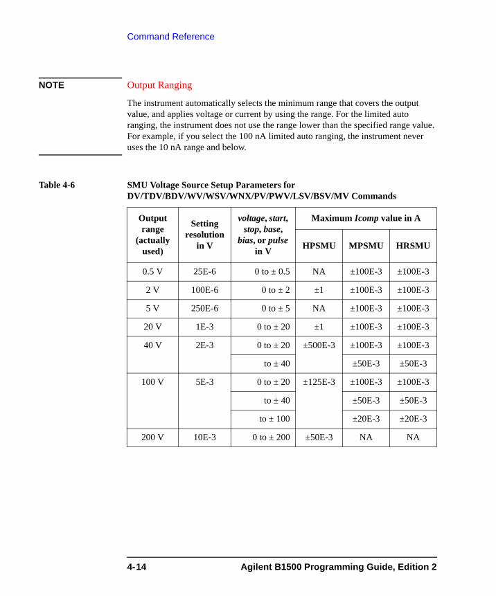
Command Reference
NOTE Output Ranging
The instrument automatically selects the minimum range that covers the output value, and applies voltage or current by using the range. For the limited auto ranging, the instrument does not use the range lower than the specified range value. For example, if you select the 100 nA limited auto ranging, the instrument never uses the 10 nA range and below.
Table 4-6 SMU Voltage Source Setup Parameters for DV/TDV/BDV/WV/WSV/WNX/PV/PWV/LSV/BSV/MV Commands
Output range
(actually used)
Setting resolution
in V
voltage, start, stop, base,
bias, or pulse in V
Maximum Icomp value in A
HPSMU MPSMU HRSMU
0.5 V 25E-6 0 to ± 0.5 NA ±100E-3 ±100E-3
2 V 100E-6 0 to ± 2 ±1 ±100E-3 ±100E-3
5 V 250E-6 0 to ± 5 NA ±100E-3 ±100E-3
20 V 1E-3 0 to ± 20 ±1 ±100E-3 ±100E-3
40 V 2E-3 0 to ± 20 ±500E-3 ±100E-3 ±100E-3
to ± 40 ±50E-3 ±50E-3
100 V 5E-3 0 to ± 20 ±125E-3 ±100E-3 ±100E-3
to ± 40 ±50E-3 ±50E-3
to ± 100 ±20E-3 ±20E-3
200 V 10E-3 0 to ± 200 ±50E-3 NA NA
4-14 Agilent B1500 Programming Guide, Edition 2
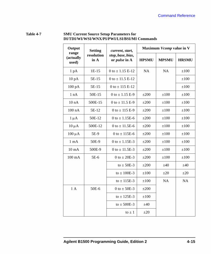
Command Reference
Table 4-7 SMU Current Source Setup Parameters for DI/TDI/WI/WSI/WNX/PI/PWI/LSI/BSI/MI Commands
Output range
(actually used)
Setting resolution
in A
current, start, stop, base, bias, or pulse in A
Maximum Vcomp value in V
HPSMU MPSMU HRSMU
1 pA 1E-15 0 to ± 1.15 E-12 NA NA ±100
10 pA 5E-15 0 to ± 11.5 E-12 ±100
100 pA 5E-15 0 to ± 115 E-12 ±100
1 nA 50E-15 0 to ± 1.15 E-9 ±200 ±100 ±100
10 nA 500E-15 0 to ± 11.5 E-9 ±200 ±100 ±100
100 nA 5E-12 0 to ± 115 E-9 ±200 ±100 ±100
1 μA 50E-12 0 to ± 1.15E-6 ±200 ±100 ±100
10 μA 500E-12 0 to ± 11.5E-6 ±200 ±100 ±100
100 μA 5E-9 0 to ± 115E-6 ±200 ±100 ±100
1 mA 50E-9 0 to ± 1.15E-3 ±200 ±100 ±100
10 mA 500E-9 0 to ± 11.5E-3 ±200 ±100 ±100
100 mA 5E-6 0 to ± 20E-3 ±200 ±100 ±100
to ± 50E-3 ±200 ±40 ±40
to ± 100E-3 ±100 ±20 ±20
to ± 115E-3 ±100 NA NA
1 A 50E-6 0 to ± 50E-3 ±200
to ± 125E-3 ±100
to ± 500E-3 ±40
to ± 1 ±20
Agilent B1500 Programming Guide, Edition 2 4-15

Command Reference
Table 4-8 MFCMU Measurement Parameters
mode Primary Parameter Secondary Parameter
1 R (resistance, Ω) X (reactance, Ω)
2 G (conductance, S) B (susceptance, S)
10 Z (impedance, Ω) θ (phase, radian)
11 Z (impedance, Ω) θ (phase, degree)
20 Y (admittance, S) θ (phase, radian)
21 Y (admittance, S) θ (phase, degree)
100 Cp (parallel capacitance, F) G (conductance, S)
101 Cp (parallel capacitance, F) D (dissipation factor)
102 Cp (parallel capacitance, F) Q (quality factor)
103 Cp (parallel capacitance, F) Rp (parallel resistance, Ω)
200 Cs (series capacitance, F) Rs (series resistance, Ω)
201 Cs (series capacitance, F) D (dissipation factor)
202 Cs (series capacitance, F) Q (quality factor)
300 Lp (parallel inductance, H) G (conductance, S)
301 Lp (parallel inductance, H) D (dissipation factor)
302 Lp (parallel inductance, H) Q (quality factor)
303 Lp (parallel inductance, H) Rp (parallel resistance, Ω)
400 Ls (series inductance, H) Rs (series resistance, Ω)
401 Ls (series inductance, H) D (dissipation factor)
402 Ls (series inductance, H) Q (quality factor)
4-16 Agilent B1500 Programming Guide, Edition 2
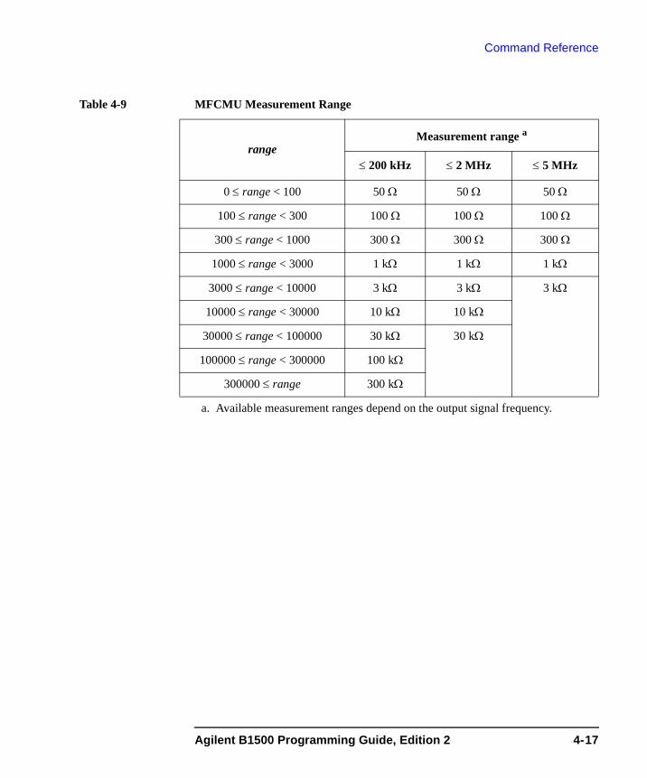
Command Reference
Table 4-9 MFCMU Measurement Range
rangeMeasurement range a
a. Available measurement ranges depend on the output signal frequency.
≤ 200 kHz ≤ 2 MHz ≤ 5 MHz
0 ≤ range < 100 50 Ω 50 Ω 50 Ω
100 ≤ range < 300 100 Ω 100 Ω 100 Ω
300 ≤ range < 1000 300 Ω 300 Ω 300 Ω
1000 ≤ range < 3000 1 kΩ 1 kΩ 1 kΩ
3000 ≤ range < 10000 3 kΩ 3 kΩ 3 kΩ
10000 ≤ range < 30000 10 kΩ 10 kΩ
30000 ≤ range < 100000 30 kΩ 30 kΩ
100000 ≤ range < 300000 100 kΩ
300000 ≤ range 300 kΩ
Agilent B1500 Programming Guide, Edition 2 4-17
Command Reference
Command ReferenceThis section contains detailed descriptions of all GPIB commands. The commands are listed in alphabetical order. Each entry:
1. Defines one GPIB command
2. Describes the execution conditions, if any exist
3. Describes the syntax
4. Lists the parameters
5. Shows the query response after command execution, if there is a query command
6. Explains any additional information
7. Provides examples
The following conventions are used in this section.
parameter Required command parameters, for which you must substitute a value or variable.
[parameter] Optional command parameters, for which you may substitute a value or omit it.
4-18 Agilent B1500 Programming Guide, Edition 2
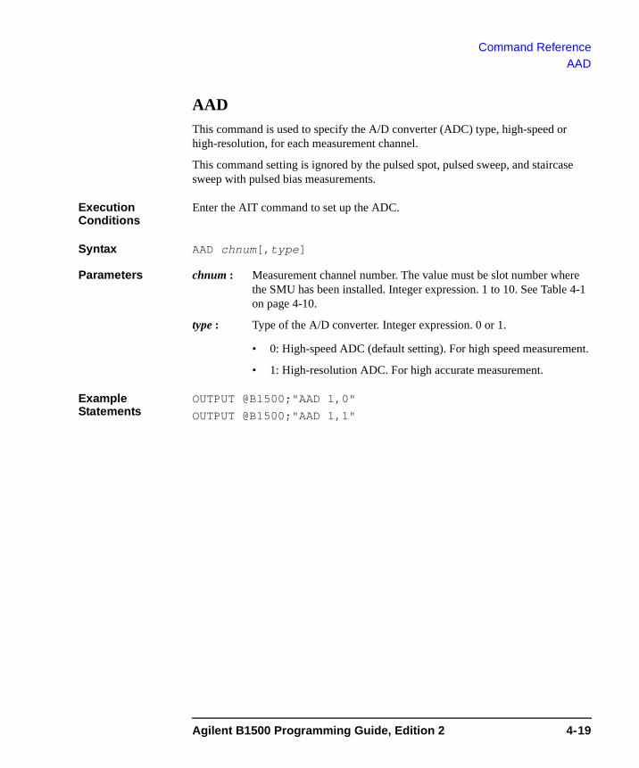
Command ReferenceAAD
AADThis command is used to specify the A/D converter (ADC) type, high-speed or high-resolution, for each measurement channel.
This command setting is ignored by the pulsed spot, pulsed sweep, and staircase sweep with pulsed bias measurements.
Execution Conditions
Enter the AIT command to set up the ADC.
Syntax AAD chnum[,type]
Parameters chnum : Measurement channel number. The value must be slot number where the SMU has been installed. Integer expression. 1 to 10. See Table 4-1 on page 4-10.
type : Type of the A/D converter. Integer expression. 0 or 1.
• 0: High-speed ADC (default setting). For high speed measurement.
• 1: High-resolution ADC. For high accurate measurement.
Example Statements
OUTPUT @B1500;"AAD 1,0"
OUTPUT @B1500;"AAD 1,1"
Agilent B1500 Programming Guide, Edition 2 4-19
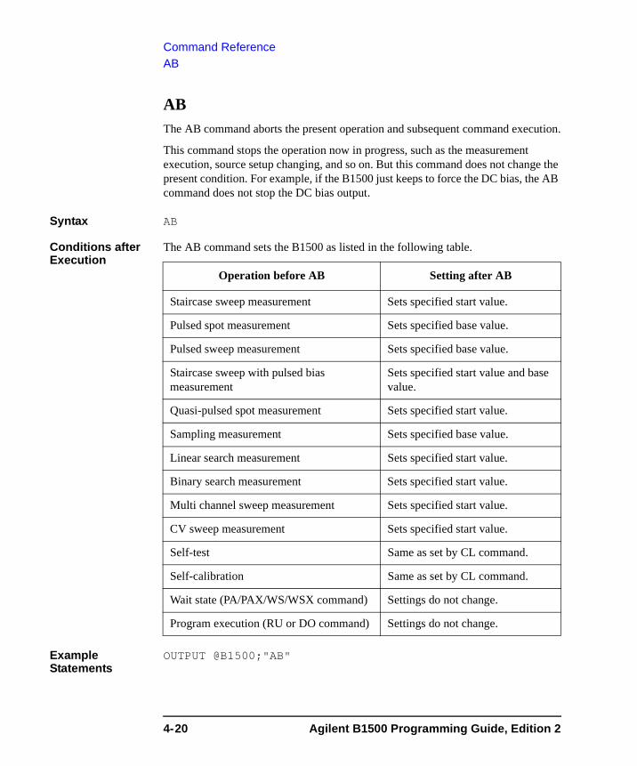
Command ReferenceAB
AB The AB command aborts the present operation and subsequent command execution.
This command stops the operation now in progress, such as the measurement execution, source setup changing, and so on. But this command does not change the present condition. For example, if the B1500 just keeps to force the DC bias, the AB command does not stop the DC bias output.
Syntax AB
Conditions after Execution
The AB command sets the B1500 as listed in the following table.
Example Statements
OUTPUT @B1500;"AB"
Operation before AB Setting after AB
Staircase sweep measurement Sets specified start value.
Pulsed spot measurement Sets specified base value.
Pulsed sweep measurement Sets specified base value.
Staircase sweep with pulsed bias measurement
Sets specified start value and base value.
Quasi-pulsed spot measurement Sets specified start value.
Sampling measurement Sets specified base value.
Linear search measurement Sets specified start value.
Binary search measurement Sets specified start value.
Multi channel sweep measurement Sets specified start value.
CV sweep measurement Sets specified start value.
Self-test Same as set by CL command.
Self-calibration Same as set by CL command.
Wait state (PA/PAX/WS/WSX command) Settings do not change.
Program execution (RU or DO command) Settings do not change.
4-20 Agilent B1500 Programming Guide, Edition 2
Command ReferenceAB
Remarks If you start an operation that you may want to abort, do not send any command after the command or command string that starts the operation. If you do, the AB command cannot enter the command input buffer until the intervening command execution starts, so the operation cannot be aborted. In this case, use the device clear (HP BASIC CLEAR command) to end the operation.
If the AB command is entered in a command string, the other commands in the string are not executed. For example, the CN command in the following command string is not executed.
OUTPUT @B1500;"AB;CN"
During sweep measurement, if the B1500 receives the AB command, it returns only the measurement data obtained before abort. Then the dummy data is not returned.
For the quasi-pulsed spot measurement, the B1500 cannot receive any command during the settling detection. So the AB command cannot abort the operation, and it will be performed after the settling detection.
Agilent B1500 Programming Guide, Edition 2 4-21
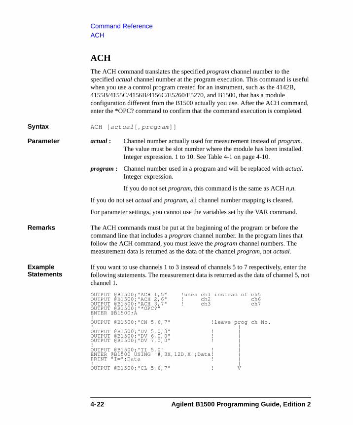
Command ReferenceACH
ACHThe ACH command translates the specified program channel number to the specified actual channel number at the program execution. This command is useful when you use a control program created for an instrument, such as the 4142B, 4155B/4155C/4156B/4156C/E5260/E5270, and B1500, that has a module configuration different from the B1500 actually you use. After the ACH command, enter the *OPC? command to confirm that the command execution is completed.
Syntax ACH [actual[,program]]
Parameter actual : Channel number actually used for measurement instead of program. The value must be slot number where the module has been installed. Integer expression. 1 to 10. See Table 4-1 on page 4-10.
program : Channel number used in a program and will be replaced with actual. Integer expression.
If you do not set program, this command is the same as ACH n,n.
If you do not set actual and program, all channel number mapping is cleared.
For parameter settings, you cannot use the variables set by the VAR command.
Remarks The ACH commands must be put at the beginning of the program or before the command line that includes a program channel number. In the program lines that follow the ACH command, you must leave the program channel numbers. The measurement data is returned as the data of the channel program, not actual.
Example Statements
If you want to use channels 1 to 3 instead of channels 5 to 7 respectively, enter the following statements. The measurement data is returned as the data of channel 5, not channel 1.
OUTPUT @B1500;"ACH 1,5" !uses ch1 instead of ch5OUTPUT @B1500;"ACH 2,6" ! ch2 ch6OUTPUT @B1500;"ACH 3,7" ! ch3 ch7OUTPUT @B1500;"*OPC?"ENTER @B1500;A!OUTPUT @B1500;"CN 5,6,7" !leave prog ch No.! |OUTPUT @B1500;"DV 5,0,3" ! |OUTPUT @B1500;"DV 6,0,0" ! |OUTPUT @B1500;"DV 7,0,0" ! |! |OUTPUT @B1500;"TI 5,0" ! |ENTER @B1500 USING "#,3X,12D,X";Data! |PRINT "I=";Data ! |! |OUTPUT @B1500;"CL 5,6,7" ! V
4-22 Agilent B1500 Programming Guide, Edition 2
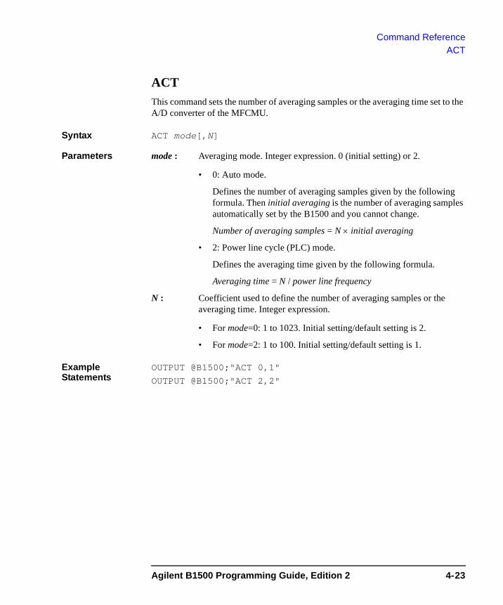
Command ReferenceACT
ACTThis command sets the number of averaging samples or the averaging time set to the A/D converter of the MFCMU.
Syntax ACT mode[,N]
Parameters mode : Averaging mode. Integer expression. 0 (initial setting) or 2.
• 0: Auto mode.
Defines the number of averaging samples given by the following formula. Then initial averaging is the number of averaging samples automatically set by the B1500 and you cannot change.
Number of averaging samples = N × initial averaging
• 2: Power line cycle (PLC) mode.
Defines the averaging time given by the following formula.
Averaging time = N / power line frequency
N : Coefficient used to define the number of averaging samples or the averaging time. Integer expression.
• For mode=0: 1 to 1023. Initial setting/default setting is 2.
• For mode=2: 1 to 100. Initial setting/default setting is 1.
Example Statements
OUTPUT @B1500;"ACT 0,1"
OUTPUT @B1500;"ACT 2,2"
Agilent B1500 Programming Guide, Edition 2 4-23
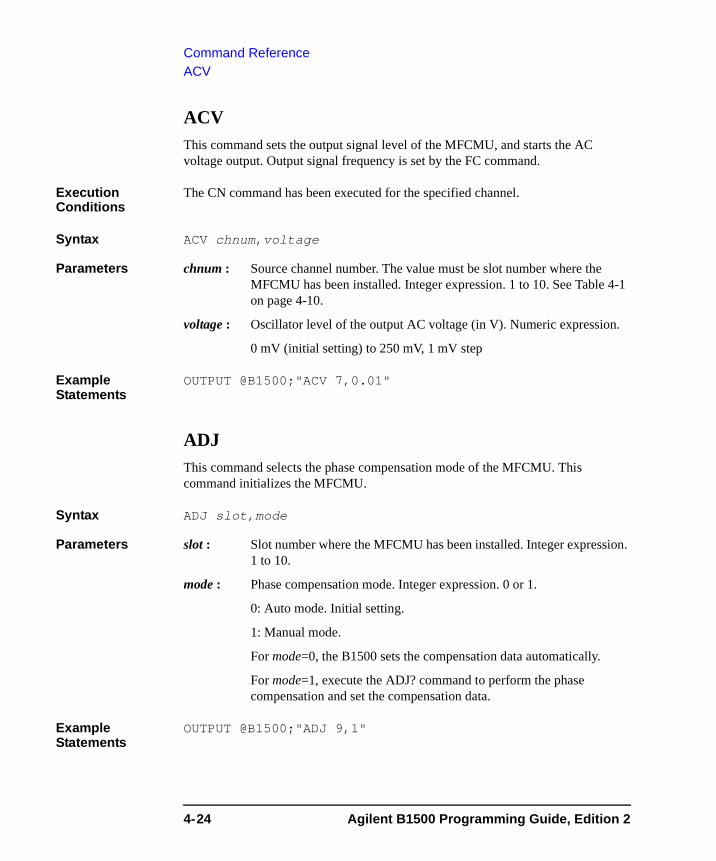
Command ReferenceACV
ACVThis command sets the output signal level of the MFCMU, and starts the AC voltage output. Output signal frequency is set by the FC command.
Execution Conditions
The CN command has been executed for the specified channel.
Syntax ACV chnum,voltage
Parameters chnum : Source channel number. The value must be slot number where the MFCMU has been installed. Integer expression. 1 to 10. See Table 4-1 on page 4-10.
voltage : Oscillator level of the output AC voltage (in V). Numeric expression.
0 mV (initial setting) to 250 mV, 1 mV step
Example Statements
OUTPUT @B1500;"ACV 7,0.01"
ADJThis command selects the phase compensation mode of the MFCMU. This command initializes the MFCMU.
Syntax ADJ slot,mode
Parameters slot : Slot number where the MFCMU has been installed. Integer expression. 1 to 10.
mode : Phase compensation mode. Integer expression. 0 or 1.
0: Auto mode. Initial setting.
1: Manual mode.
For mode=0, the B1500 sets the compensation data automatically.
For mode=1, execute the ADJ? command to perform the phase compensation and set the compensation data.
Example Statements
OUTPUT @B1500;"ADJ 9,1"
4-24 Agilent B1500 Programming Guide, Edition 2
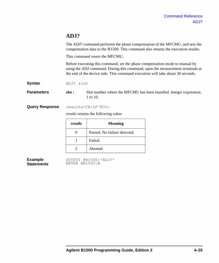
Command ReferenceADJ?
ADJ?The ADJ? command performs the phase compensation of the MFCMU, and sets the compensation data to the B1500. This command also returns the execution results.
This command resets the MFCMU.
Before executing this command, set the phase compensation mode to manual by using the ADJ command. During this commnad, open the measurement terminals at the end of the device side. This command execution will take about 30 seconds.
Syntax ADJ? slot
Parameters slot : Slot number where the MFCMU has been installed. Integer expression. 1 to 10.
Query Response results<CR/LF^EOI>
results returns the following value.
Example Statements
OUTPUT @B1500;"ADJ?" ENTER @B1500;A
results Meaning
0 Passed. No failure detected.
1 Failed.
2 Aborted.
Agilent B1500 Programming Guide, Edition 2 4-25

Command ReferenceAIT
AITThis command is used to set the integration time or the number of averaging samples of the A/D converter (ADC) for each ADC type.
This command setting is ignored by the pulsed spot, pulsed sweep, and staircase sweep with pulsed bias measurements.
Execution Conditions
Enter the AAD command to specify the ADC type for each measurement channel.
Syntax AIT type,mode[,N]
Parameters type : A/D converter type. Integer expression.
0: High-speed A/D converter.
1: High-resolution A/D converter.
mode : ADC operation mode. Integer expression. Initial setting is 0.
0: Auto mode.
1: Manual mode.
2: Power line cycle (PLC) mode.
N : Coefficient used to define the integration time or the number of averaging samples. Integer expression. See Table 4-10.
Example Statements
OUTPUT @B1500;"AIT 0,2,1"
OUTPUT @B1500;"AIT 1,1,10"
4-26 Agilent B1500 Programming Guide, Edition 2
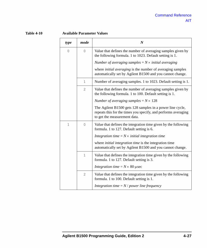
Command ReferenceAIT
Table 4-10 Available Parameter Values
type mode N
0 0 Value that defines the number of averaging samples given by the following formula. 1 to 1023. Default setting is 1.
Number of averaging samples = N × initial averaging
where initial averaging is the number of averaging samples automatically set by Agilent B1500 and you cannot change.
1 Number of averaging samples. 1 to 1023. Default setting is 1.
2 Value that defines the number of averaging samples given by the following formula. 1 to 100. Default setting is 1.
Number of averaging samples = N × 128
The Agilent B1500 gets 128 samples in a power line cycle, repeats this for the times you specify, and performs averaging to get the measurement data.
1 0 Value that defines the integration time given by the following formula. 1 to 127. Default setting is 6.
Integration time = N × initial integration time
where initial integration time is the integration time automatically set by Agilent B1500 and you cannot change.
1 Value that defines the integration time given by the following formula. 1 to 127. Default setting is 3.
Integration time = N × 80 μsec
2 Value that defines the integration time given by the following formula. 1 to 100. Default setting is 1.
Integration time = N / power line frequency
Agilent B1500 Programming Guide, Edition 2 4-27

Command ReferenceAV
AVThis command sets the number of averaging samples of the A/D converter (ADC).
This command setting is ignored by the pulsed spot, pulsed sweep, and staircase sweep with pulsed bias measurements.
Syntax AV number[,mode]
Parameters number : 1 to 1023, or −1 to −100. Initial setting is 1.
For positive number input, this value specifies the number of samples depended on the mode value. See below.
For negative number input, this parameter specifies the number of power line cycles (PLC) for one point measurement. The Agilent B1500 gets 128 samples in 1 PLC. Ignore the mode parameter.
mode : Averaging mode. Integer expression. This parameter is meaningless for negative number.
0: Auto mode (default setting).
Number of samples = number × initial number
1: Manual mode.
Number of samples = number
where initial number means the number of samples the Agilent B1500 automatically sets and you cannot change. For voltage measurement, initial number=1. For current measurement, see Table 4-11.
If you select the manual mode, number must be initial number or more to satisfy the specifications.
Example Statements
OUTPUT @B1500;"AV 10"
OUTPUT @B1500;"AV -50"
OUTPUT @B1500;"AV 100,1"
4-28 Agilent B1500 Programming Guide, Edition 2
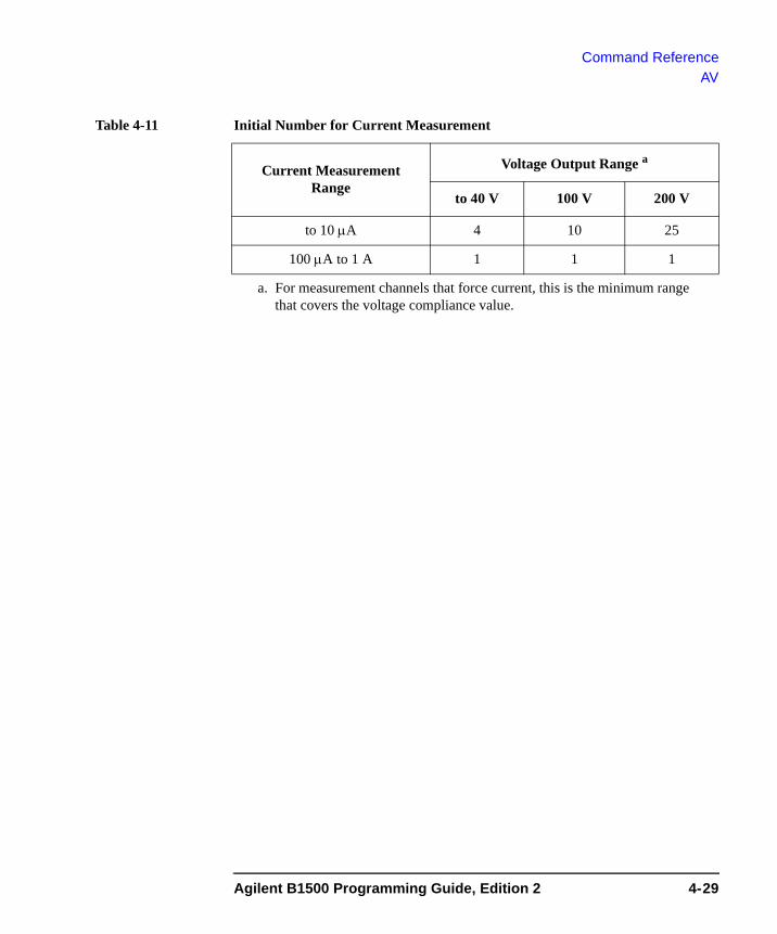
Command ReferenceAV
Table 4-11 Initial Number for Current Measurement
Current Measurement Range
Voltage Output Range a
a. For measurement channels that force current, this is the minimum range that covers the voltage compliance value.
to 40 V 100 V 200 V
to 10 μA 4 10 25
100 μA to 1 A 1 1 1
Agilent B1500 Programming Guide, Edition 2 4-29
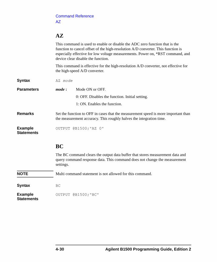
Command ReferenceAZ
AZ This command is used to enable or disable the ADC zero function that is the function to cancel offset of the high-resolution A/D converter. This function is especially effective for low voltage measurements. Power on, *RST command, and device clear disable the function.
This command is effective for the high-resolution A/D converter, not effective for the high-speed A/D converter.
Syntax AZ mode
Parameters mode : Mode ON or OFF.
0: OFF. Disables the function. Initial setting.
1: ON. Enables the function.
Remarks Set the function to OFF in cases that the measurement speed is more important than the measurement accuracy. This roughly halves the integration time.
Example Statements
OUTPUT @B1500;"AZ 0"
BC The BC command clears the output data buffer that stores measurement data and query command response data. This command does not change the measurement settings.
NOTE Multi command statement is not allowed for this command.
Syntax BC
Example Statements
OUTPUT @B1500;"BC"
4-30 Agilent B1500 Programming Guide, Edition 2
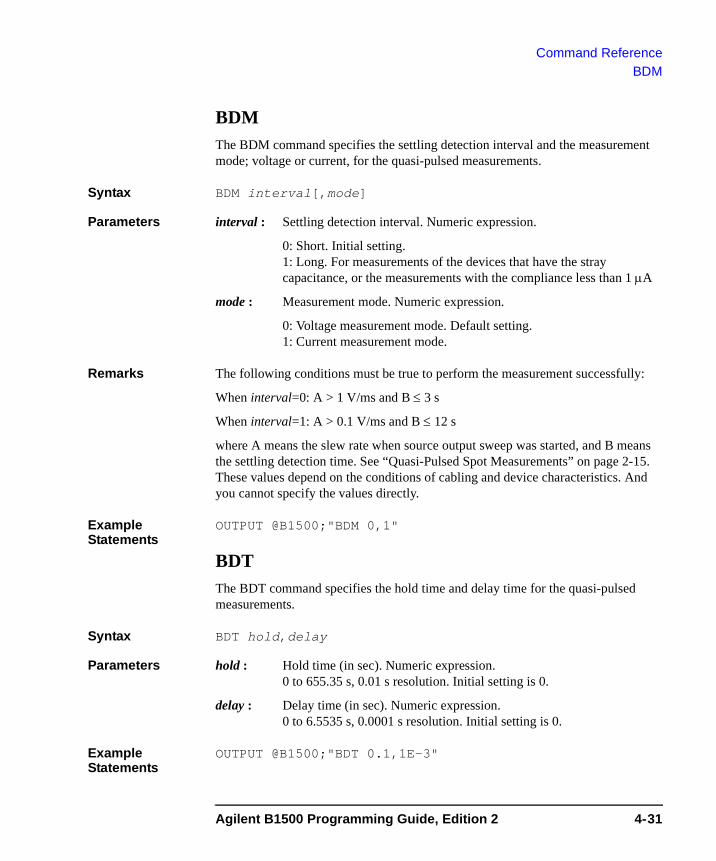
Command ReferenceBDM
BDMThe BDM command specifies the settling detection interval and the measurement mode; voltage or current, for the quasi-pulsed measurements.
Syntax BDM interval[,mode]
Parameters interval : Settling detection interval. Numeric expression.
0: Short. Initial setting.1: Long. For measurements of the devices that have the stray capacitance, or the measurements with the compliance less than 1 μA
mode : Measurement mode. Numeric expression.
0: Voltage measurement mode. Default setting.1: Current measurement mode.
Remarks The following conditions must be true to perform the measurement successfully:
When interval=0: A > 1 V/ms and B ≤ 3 s
When interval=1: A > 0.1 V/ms and B ≤ 12 s
where A means the slew rate when source output sweep was started, and B means the settling detection time. See “Quasi-Pulsed Spot Measurements” on page 2-15. These values depend on the conditions of cabling and device characteristics. And you cannot specify the values directly.
Example Statements
OUTPUT @B1500;"BDM 0,1"
BDTThe BDT command specifies the hold time and delay time for the quasi-pulsed measurements.
Syntax BDT hold,delay
Parameters hold : Hold time (in sec). Numeric expression.0 to 655.35 s, 0.01 s resolution. Initial setting is 0.
delay : Delay time (in sec). Numeric expression. 0 to 6.5535 s, 0.0001 s resolution. Initial setting is 0.
Example Statements
OUTPUT @B1500;"BDT 0.1,1E-3"
Agilent B1500 Programming Guide, Edition 2 4-31
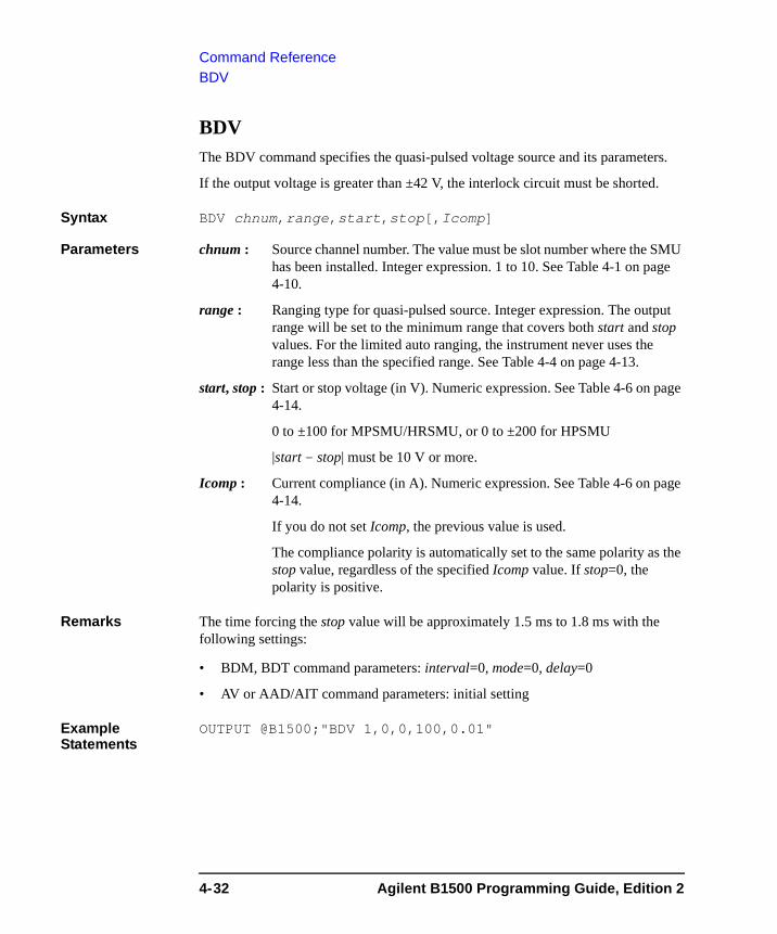
Command ReferenceBDV
BDVThe BDV command specifies the quasi-pulsed voltage source and its parameters.
If the output voltage is greater than ±42 V, the interlock circuit must be shorted.
Syntax BDV chnum,range,start,stop[,Icomp]
Parameters chnum : Source channel number. The value must be slot number where the SMU has been installed. Integer expression. 1 to 10. See Table 4-1 on page 4-10.
range : Ranging type for quasi-pulsed source. Integer expression. The output range will be set to the minimum range that covers both start and stop values. For the limited auto ranging, the instrument never uses the range less than the specified range. See Table 4-4 on page 4-13.
start, stop : Start or stop voltage (in V). Numeric expression. See Table 4-6 on page 4-14.
0 to ±100 for MPSMU/HRSMU, or 0 to ±200 for HPSMU
|start - stop| must be 10 V or more.
Icomp : Current compliance (in A). Numeric expression. See Table 4-6 on page 4-14.
If you do not set Icomp, the previous value is used.
The compliance polarity is automatically set to the same polarity as the stop value, regardless of the specified Icomp value. If stop=0, the polarity is positive.
Remarks The time forcing the stop value will be approximately 1.5 ms to 1.8 ms with the following settings:
• BDM, BDT command parameters: interval=0, mode=0, delay=0
• AV or AAD/AIT command parameters: initial setting
Example Statements
OUTPUT @B1500;"BDV 1,0,0,100,0.01"
4-32 Agilent B1500 Programming Guide, Edition 2
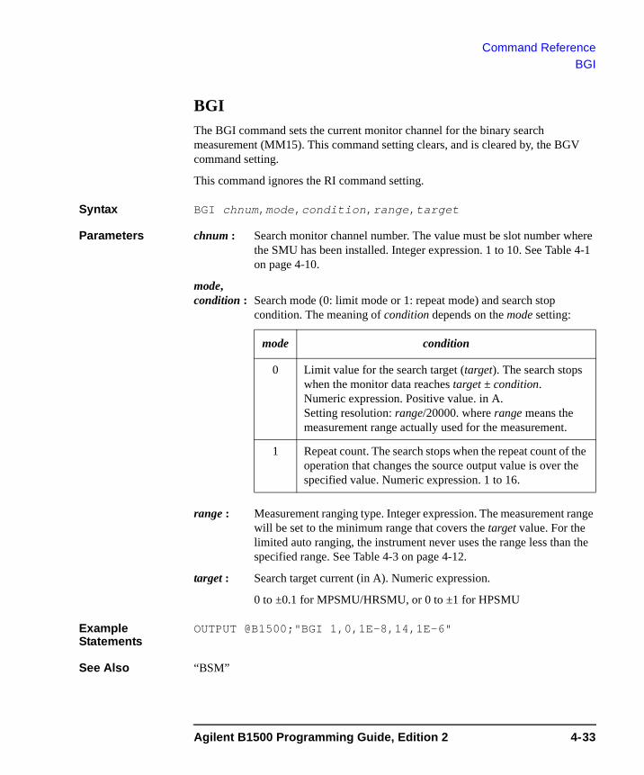
Command ReferenceBGI
BGIThe BGI command sets the current monitor channel for the binary search measurement (MM15). This command setting clears, and is cleared by, the BGV command setting.
This command ignores the RI command setting.
Syntax BGI chnum,mode,condition,range,target
Parameters chnum : Search monitor channel number. The value must be slot number where the SMU has been installed. Integer expression. 1 to 10. See Table 4-1 on page 4-10.
mode, condition : Search mode (0: limit mode or 1: repeat mode) and search stop
condition. The meaning of condition depends on the mode setting:
range : Measurement ranging type. Integer expression. The measurement range will be set to the minimum range that covers the target value. For the limited auto ranging, the instrument never uses the range less than the specified range. See Table 4-3 on page 4-12.
target : Search target current (in A). Numeric expression.
0 to ±0.1 for MPSMU/HRSMU, or 0 to ±1 for HPSMU
Example Statements
OUTPUT @B1500;"BGI 1,0,1E-8,14,1E-6"
See Also “BSM”
mode condition
0 Limit value for the search target (target). The search stops when the monitor data reaches target ± condition. Numeric expression. Positive value. in A. Setting resolution: range/20000. where range means the measurement range actually used for the measurement.
1 Repeat count. The search stops when the repeat count of the operation that changes the source output value is over the specified value. Numeric expression. 1 to 16.
Agilent B1500 Programming Guide, Edition 2 4-33
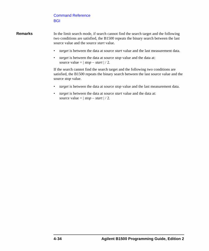
Command ReferenceBGI
Remarks In the limit search mode, if search cannot find the search target and the following two conditions are satisfied, the B1500 repeats the binary search between the last source value and the source start value.
• target is between the data at source start value and the last measurement data.
• target is between the data at source stop value and the data at:source value = | stop − start | / 2.
If the search cannot find the search target and the following two conditions are satisfied, the B1500 repeats the binary search between the last source value and the source stop value.
• target is between the data at source stop value and the last measurement data.
• target is between the data at source start value and the data at:source value = | stop − start | / 2.
4-34 Agilent B1500 Programming Guide, Edition 2
Command ReferenceBGV
BGV The BGV command specifies the voltage monitor channel and its search parameters for the binary search measurement (MM15). This command setting clears, and is cleared by, the BGI command setting.
This command ignores the RV command setting.
Syntax BGV chnum,mode,condition,range,target
Parameters chnum : Search monitor channel number. The value must be slot number where the SMU has been installed. Integer expression. 1 to 10. See Table 4-1 on page 4-10.
mode, condition : Search mode (0: limit mode or 1: repeat mode) and search stop
condition. The meaning of condition depends on the mode setting:
range : Measurement ranging type. Integer expression. The measurement range will be set to the minimum range that covers the target value. For the limited auto ranging, the instrument never uses the range less than the specified range. See Table 4-2 on page 4-11.
target : Search target voltage (in V). Numeric expression.
0 to ±100 for MPSMU/HRSMU, or 0 to ±200 for HPSMU
Example Statements
OUTPUT @B1500;"BGV 1,0,0.1,12,5"
See Also “BSM”
mode condition
0 Limit value for the search target (target). The search stops when the monitor data reaches target ± condition. Numeric expression. Positive value. in V. Setting resolution: range/20000. where range means the measurement range actually used for the measurement.
1 Repeat count. The search stops when the repeat count of the operation that changes the source output value is over the specified value. Numeric expression. 1 to 16.
Agilent B1500 Programming Guide, Edition 2 4-35

Command ReferenceBGV
Remarks In the limit search mode, if search cannot find the search target and the following two conditions are satisfied, the B1500 repeats the binary search between the last source value and the source start value.
• target is between the data at source start value and the last measurement data.
• target is between the data at source stop value and the data at:source value = | stop − start | / 2.
If the search cannot find the search target and the following two conditions are satisfied, the B1500 repeats the binary search between the last source value and the source stop value.
• target is between the data at source stop value and the last measurement data.
• target is between the data at source start value and the data at:source value = | stop − start | / 2.
4-36 Agilent B1500 Programming Guide, Edition 2
Command ReferenceBSI
BSI The BSI command sets the current search source for the binary search measurement (MM15). After search stops, the search channel forces the value specified by the BSM command.
This command clears the BSV, BSSI, and BSSV command settings.
This command setting is cleared by the BSV command.
If Vcomp value is greater than ±42 V, the interlock circuit must be shorted.
Syntax BSI chnum,range,start,stop[,Vcomp]
Parameters chnum : Search source channel number. The value must be slot number where the SMU has been installed. Integer expression. 1 to 10. See Table 4-1 on page 4-10.
range : Output ranging type. Integer expression. The output range will be set to the minimum range that covers both start and stop values. For the limited auto ranging, the instrument never uses the range less than the specified range. See Table 4-5 on page 4-13.
start, stop : Search start or stop current (in A). Numeric expression. See Table 4-7 on page 4-15. The start and stop must have different values.
0 to ±0.1 for MPSMU/HRSMU, or 0 to ±1 for HPSMU
Vcomp : Voltage compliance value (in V). Numeric expression. See Table 4-7 on page 4-15. If you do not specify Vcomp, the previous value is set.
Example Statements
OUTPUT @B1500;"BSI 1,0,1E-12,1E-6,10"
Agilent B1500 Programming Guide, Edition 2 4-37
Command ReferenceBSM
BSMThe BSM command specifies the search source control mode in the binary search measurement (MM15), and enables or disables the automatic abort function. The automatic abort function stops the search operation when one of the following conditions occurs:
• Compliance on the measurement channel
• Compliance on the non-measurement channel
• Overflow on the AD converter
• Oscillation on any channel
This command also sets the post search condition for the binary search sources. After the search measurement is normally completed, the binary search sources force the value specified by the post parameter.
If the search operation is stopped by the automatic abort function, the binary search sources force the start value after search.
Syntax BSM mode,abort[,post]
Parameters mode : Source output control mode, 0 (normal mode) or 1 (cautious mode). If you do not enter this command, the normal mode is set. See Figure 4-1.
abort : Automatic abort function. Integer expression.
1: Disables the function. Initial setting.
2: Enables the function.
post : Source output value after the search operation is normally completed. Integer expression.
1: Start value. Initial setting.
2: Stop value.
3: Output value when the search target value is get.
If this parameter is not set, the search source forces the start value.
Example Statements
OUTPUT @B1500;"BSM 1,2,3"
4-38 Agilent B1500 Programming Guide, Edition 2
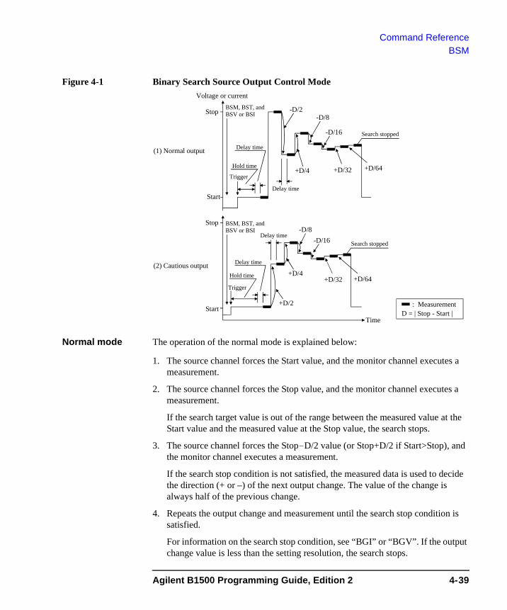
Command ReferenceBSM
Figure 4-1 Binary Search Source Output Control Mode
Normal mode The operation of the normal mode is explained below:
1. The source channel forces the Start value, and the monitor channel executes a measurement.
2. The source channel forces the Stop value, and the monitor channel executes a measurement.
If the search target value is out of the range between the measured value at the Start value and the measured value at the Stop value, the search stops.
3. The source channel forces the Stop-D/2 value (or Stop+D/2 if Start>Stop), and the monitor channel executes a measurement.
If the search stop condition is not satisfied, the measured data is used to decide the direction (+ or –) of the next output change. The value of the change is always half of the previous change.
4. Repeats the output change and measurement until the search stop condition is satisfied.
For information on the search stop condition, see “BGI” or “BGV”. If the output change value is less than the setting resolution, the search stops.
Start
Stop
D = | Stop - Start |
+D/4
-D/2-D/8
-D/16
(1) Normal output
Search stopped
+D/32 +D/64
: MeasurementStart
Stop
+D/4
+D/2
-D/8-D/16
(2) Cautious output
Search stopped
+D/32 +D/64
Time
Voltage or current
Hold time
Delay time
Hold time
Delay time
Delay time
Delay time
Trigger
Trigger
BSM, BST, and BSV or BSI
BSM, BST, and BSV or BSI
Agilent B1500 Programming Guide, Edition 2 4-39
Command ReferenceBSM
Cautious mode The operation of the cautious mode is explained below:
1. The source channel forces the Start value, and the monitor channel executes a measurement.
2. The source channel forces the Start+D/2 value (or Start-D/2 if Start>Stop), and the monitor channel executes a measurement.
If the search stop condition is not satisfied, the measured data is used to decide the direction (+ or –) of the next output change. The value of the change is always half of the previous change.
3. Repeats the output change and measurement until the search stop condition is satisfied.
For information on the search stop condition, see “BGI” or “BGV”. If the output change value is less than the setting resolution, the search stops.
4-40 Agilent B1500 Programming Guide, Edition 2
Command ReferenceBSSI
BSSI The BSSI command sets the synchronous current source for the binary search measurement (MM15). The synchronous source output will be:
Synchronous source output = polarity × BSI source output + offset
where BSI source output means the output set by the BSI command.
This command setting is cleared by the BSV/BSI command.
Execution Conditions
The BSI command must be sent before sending this command.
Syntax BSSI chnum,polarity,offset[,Vcomp]
Parameters chnum : Synchronous source channel number. The value must be slot number where the SMU has been installed. Integer expression. 1 to 10. See Table 4-1 on page 4-10.
polarity : Polarity of the BSSI output for the BSI output.
0: Negative. BSSI output = −BSI output + offset
1: Positive. BSSI output = BSI output + offset
offset : Offset current (in A). Numeric expression.
0 to ±0.1 for MPSMU/HRSMU, or 0 to ±1 for HPSMU
Both primary and synchronous search sources will use the same output range. So check the output range set to the BSI command to determine the synchronous source outputs.
Vcomp : Voltage compliance value (in V). Numeric expression. If you do not specify Vcomp, the previous value is set.
Example Statements
OUTPUT @B1500;"BSSI 1,0,1E-6,10"
See Also Refer to Table 4-7 on page 4-15 for the source output value, output range, and the available compliance values.
Agilent B1500 Programming Guide, Edition 2 4-41
Command ReferenceBSSV
BSSV The BSSV command sets the synchronous voltage source for the binary search measurement (MM15). The synchronous source output will be:
Synchronous source output = polarity × BSV source output + offset
where BSV source output means the output set by the BSV command.
This command setting is cleared by the BSI/BSV command.
Execution Conditions
The BSV command must be sent before sending this command.
Syntax BSSV chnum,polarity,offset[,Icomp]
Parameters chnum : Synchronous source channel number. The value must be slot number where the SMU has been installed. Integer expression. 1 to 10. See Table 4-1 on page 4-10.
polarity : Polarity of the BSSV output for the BSV output.
0: Negative. BSSV output = −BSV output + offset
1: Positive. BSSV output = BSV output + offset
offset : Offset voltage (in V). Numeric expression.
0 to ±100 for MPSMU/HRSMU, or 0 to ±200 for HPSMU
Both primary and synchronous search sources will use the same output range. So check the output range set to the BSV command to determine the synchronous source outputs.
Icomp : Current compliance value (in A). Numeric expression. If you do not specify Icomp, the previous value is set. Zero amps (0 A) is not a valid value for the Icomp parameter.
Example Statements
OUTPUT @B1500;"BSSV 1,0,5,1E-6"
See Also Refer to Table 4-6 on page 4-14 for the source output value, output range, and the available compliance values.
4-42 Agilent B1500 Programming Guide, Edition 2
Command ReferenceBST
BSTThe BST command sets the hold time and delay time for the binary search measurement (MM15). If you do not enter this command, all parameters are set to 0.
Syntax BST hold,delay
Parameters hold : Hold time (in seconds) that is the wait time after starting the search measurement and before starting the delay time for the first search point. Numeric expression.
0 to 655.35 sec. 0.01 sec resolution.
delay : Delay time (in seconds) that is the wait time after starting to force a step output value and before starting a step measurement. Numeric expression.
0 to 65.535 sec. 0.0001 sec resolution.
Example Statements
OUTPUT @B1500;"BST 5,0.1"
Agilent B1500 Programming Guide, Edition 2 4-43
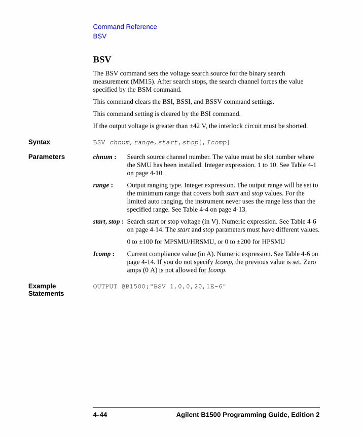
Command ReferenceBSV
BSV The BSV command sets the voltage search source for the binary search measurement (MM15). After search stops, the search channel forces the value specified by the BSM command.
This command clears the BSI, BSSI, and BSSV command settings.
This command setting is cleared by the BSI command.
If the output voltage is greater than ±42 V, the interlock circuit must be shorted.
Syntax BSV chnum,range,start,stop[,Icomp]
Parameters chnum : Search source channel number. The value must be slot number where the SMU has been installed. Integer expression. 1 to 10. See Table 4-1 on page 4-10.
range : Output ranging type. Integer expression. The output range will be set to the minimum range that covers both start and stop values. For the limited auto ranging, the instrument never uses the range less than the specified range. See Table 4-4 on page 4-13.
start, stop : Search start or stop voltage (in V). Numeric expression. See Table 4-6 on page 4-14. The start and stop parameters must have different values.
0 to ±100 for MPSMU/HRSMU, or 0 to ±200 for HPSMU
Icomp : Current compliance value (in A). Numeric expression. See Table 4-6 on page 4-14. If you do not specify Icomp, the previous value is set. Zero amps (0 A) is not allowed for Icomp.
Example Statements
OUTPUT @B1500;"BSV 1,0,0,20,1E-6"
4-44 Agilent B1500 Programming Guide, Edition 2
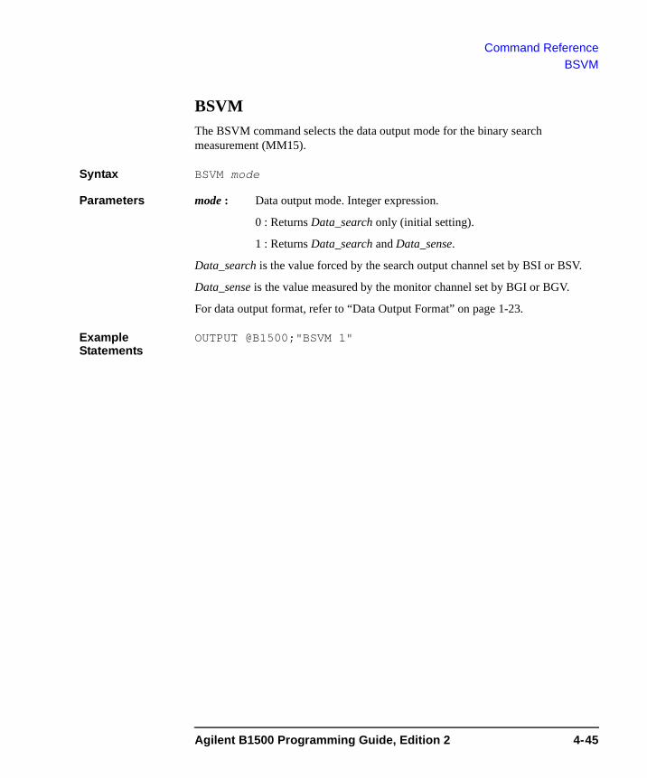
Command ReferenceBSVM
BSVMThe BSVM command selects the data output mode for the binary search measurement (MM15).
Syntax BSVM mode
Parameters mode : Data output mode. Integer expression.
0 : Returns Data_search only (initial setting).
1 : Returns Data_search and Data_sense.
Data_search is the value forced by the search output channel set by BSI or BSV.
Data_sense is the value measured by the monitor channel set by BGI or BGV.
For data output format, refer to “Data Output Format” on page 1-23.
Example Statements
OUTPUT @B1500;"BSVM 1"
Agilent B1500 Programming Guide, Edition 2 4-45
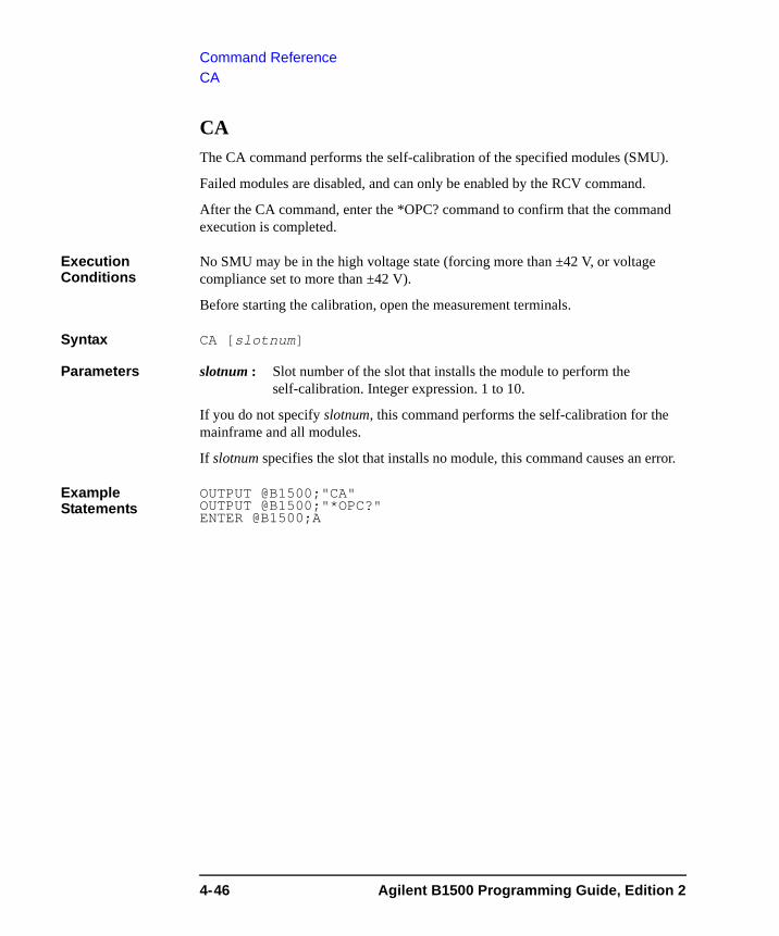
Command ReferenceCA
CA The CA command performs the self-calibration of the specified modules (SMU).
Failed modules are disabled, and can only be enabled by the RCV command.
After the CA command, enter the *OPC? command to confirm that the command execution is completed.
Execution Conditions
No SMU may be in the high voltage state (forcing more than ±42 V, or voltage compliance set to more than ±42 V).
Before starting the calibration, open the measurement terminals.
Syntax CA [slotnum]
Parameters slotnum : Slot number of the slot that installs the module to perform the self-calibration. Integer expression. 1 to 10.
If you do not specify slotnum, this command performs the self-calibration for the mainframe and all modules.
If slotnum specifies the slot that installs no module, this command causes an error.
Example Statements
OUTPUT @B1500;"CA"OUTPUT @B1500;"*OPC?"ENTER @B1500;A
4-46 Agilent B1500 Programming Guide, Edition 2
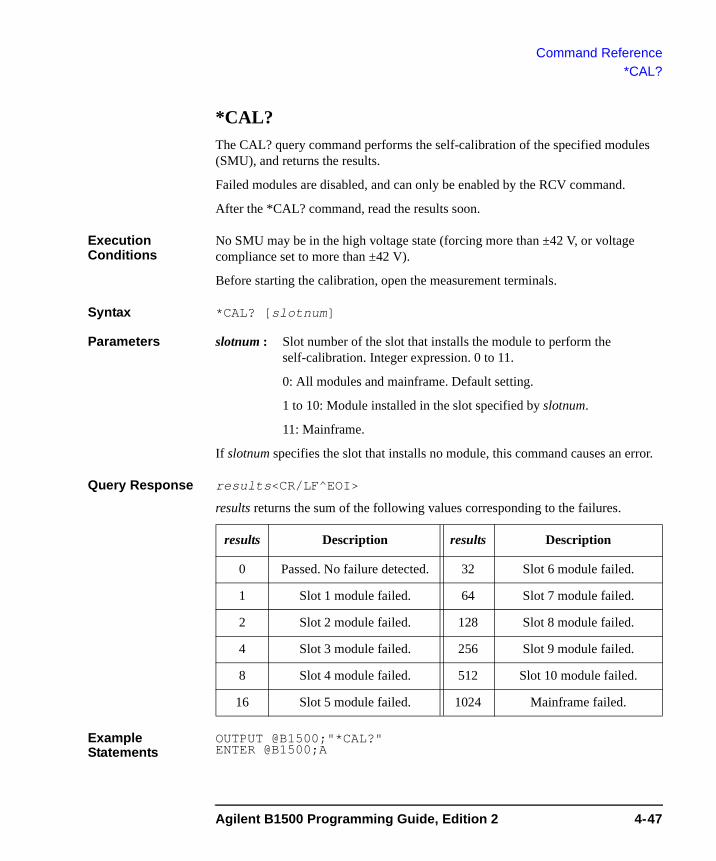
Command Reference*CAL?
*CAL? The CAL? query command performs the self-calibration of the specified modules (SMU), and returns the results.
Failed modules are disabled, and can only be enabled by the RCV command.
After the *CAL? command, read the results soon.
Execution Conditions
No SMU may be in the high voltage state (forcing more than ±42 V, or voltage compliance set to more than ±42 V).
Before starting the calibration, open the measurement terminals.
Syntax *CAL? [slotnum]
Parameters slotnum : Slot number of the slot that installs the module to perform the self-calibration. Integer expression. 0 to 11.
0: All modules and mainframe. Default setting.
1 to 10: Module installed in the slot specified by slotnum.
11: Mainframe.
If slotnum specifies the slot that installs no module, this command causes an error.
Query Response results<CR/LF^EOI>
results returns the sum of the following values corresponding to the failures.
Example Statements
OUTPUT @B1500;"*CAL?" ENTER @B1500;A
results Description results Description
0 Passed. No failure detected. 32 Slot 6 module failed.
1 Slot 1 module failed. 64 Slot 7 module failed.
2 Slot 2 module failed. 128 Slot 8 module failed.
4 Slot 3 module failed. 256 Slot 9 module failed.
8 Slot 4 module failed. 512 Slot 10 module failed.
16 Slot 5 module failed. 1024 Mainframe failed.
Agilent B1500 Programming Guide, Edition 2 4-47
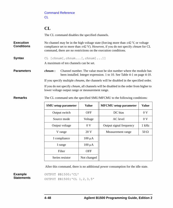
Command ReferenceCL
CL The CL command disables the specified channels.
Execution Conditions
No channel may be in the high voltage state (forcing more than ±42 V, or voltage compliance set to more than ±42 V). However, if you do not specify chnum for CL command, there are no restrictions on the execution conditions.
Syntax CL [chnum[,chnum...[,chnum]...]]
A maximum of ten channels can be set.
Parameters chnum : Channel number. The value must be slot number where the module has been installed. Integer expression. 1 to 10. See Table 4-1 on page 4-10.
If you specify multiple chnums, the channels will be disabled in the specified order.
If you do not specify chnum, all channels will be disabled in the order from higher to lower voltage output range or measurement range.
Remarks The CL command sets the specified SMU/MFCMU to the following conditions:
After this command, there is no additional power consumption for the idle state.
Example Statements
OUTPUT @B1500;"CL"
OUTPUT @B1500;"CL 1,2,3,5"
SMU setup parameter Value MFCMU setup parameter Value
Output switch OFF DC bias 0 V
Source mode Voltage AC level 0 V
Output voltage 0 V Output signal frequency 1 kHz
V range 20 V Measurement range 50 Ω
I compliance 100 μA
I range 100 μA
Filter OFF
Series resistor Not changed
4-48 Agilent B1500 Programming Guide, Edition 2
Command ReferenceCLCORR
CLCORRThis command disables the open/short/load correction function and clears the frequency list for the correction data measurement. The correction data will be invalid after this command.
Syntax CLCORR slot,mode
Parameters slot : Slot number where the MFCMU has been installed. Integer expression. 1 to 10.
mode : Command option. Integer expression. 1 or 2.
1: Just clears the frequency list.
2: Clears the frequency list and sets the default frequencies, 1 k, 2 k, 5 k, 10 k, 20 k, 50 k, 100 k, 200 k, 500 k, 1 M, 2 M, and 5 MHz.
Example Statements
OUTPUT @B1500;"CLCORR 9,1"
CM The CM command sets the SMU auto-calibration function to ON or OFF. If the following two conditions are satisfied, the B1500 automatically calibrates all modules every 30 minutes.
• Auto-calibration is ON.
• For all SMUs, the output switch has been OFF for 30 minutes.
Syntax CM mode
Parameters mode : Auto-calibration ON or OFF. Integer expression.
0: OFF (initial setting)
1: ON
Remarks Before starting the calibration, open the measurement terminals.
If the auto-calibration is enabled, do not forget to open the measurement terminals after measurements.
Example Statements
OUTPUT @B1500;"CM 0"
OUTPUT @B1500;"CM 1"
Agilent B1500 Programming Guide, Edition 2 4-49
Command ReferenceCMM
CMM The CMM command sets the SMU measurement operation mode. This command is not available for the high speed spot measurement.
Syntax CMM chnum,mode
Parameters chnum : Channel number. The value must be slot number where the SMU has been installed. Integer expression. 1 to 10. See Table 4-1 on page 4-10.
mode : SMU measurement operation mode. Integer expression.
• 0: Compliance side measurement (initial setting).
• 1: SMU always performs current measurement.
• 2: SMU always performs voltage measurement.
• 3: Force side measurement.
If mode=0, SMU measures current when it forces voltage, or measures voltage when it forces current.
If mode=3, SMU measures current when it forces current, or measures voltage when it forces voltage.
The mode setting is kept until the mode is changed by this command. If you want to return it to the initial setting, enter the CMM command with mode=0.
Example Statements
OUTPUT @B1500;"CMM 1,1"
4-50 Agilent B1500 Programming Guide, Edition 2

Command ReferenceCN
CN This command enables the specified channels.
WARNING THIS COMMAND ENABLES SMU TO FORCE DANGEROUS VOLTAGES. WHEN THE CHANNEL IS NOT IN USE, SET THE OUTPUT SWITCH TO "OFF" WHENEVER POSSIBLE.
Execution Conditions
No channel may be in the high voltage state (forcing more than ±42 V, or voltage compliance set to more than ±42 V).
Syntax CN [chnum[,chnum...[,chnum]...]]
A maximum of ten channels can be set.
Parameters chnum : Channel number. The value must be slot number where the module has been installed. Integer expression. 1 to 10. See Table 4-1 on page 4-10.
If the output switch of the specified SMU is already set to ON, no action is performed by this command.
If you do not specify chnum, all channels will be enabled in the order from lower to higher slot number.
If you specify multiple chnums, the channels will be enabled in the specified order.
If you specify the HRSMU connected to the ASU, this command enables the HRSMU and connects the path to the ASU output.
If you specify a SMU connected to the SCUU, this command enables the SMU and connects the path to the SCUU output.
If you specify the MFCMU connected to the SCUU, this command enables the MFCMU and connects the path to the SCUU output.
If you specify both MFCMU and SMU connected to the SCUU, this command causes an error.
If you enter the CN command without chnum parameter to the B1500A installed with the SCUU, this command enables the SMUs except for the SMUs connected to the SCUU, enables the MFCMU, and connects the path to the SCUU output.
Agilent B1500 Programming Guide, Edition 2 4-51
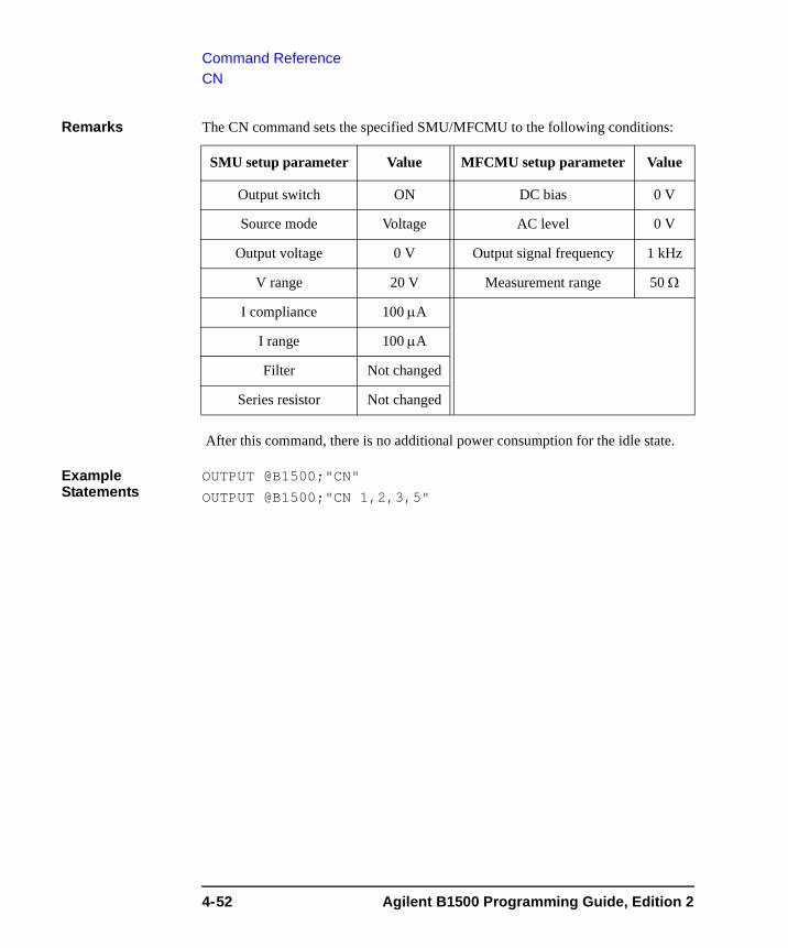
Command ReferenceCN
Remarks The CN command sets the specified SMU/MFCMU to the following conditions:
After this command, there is no additional power consumption for the idle state.
Example Statements
OUTPUT @B1500;"CN"
OUTPUT @B1500;"CN 1,2,3,5"
SMU setup parameter Value MFCMU setup parameter Value
Output switch ON DC bias 0 V
Source mode Voltage AC level 0 V
Output voltage 0 V Output signal frequency 1 kHz
V range 20 V Measurement range 50 Ω
I compliance 100 μA
I range 100 μA
Filter Not changed
Series resistor Not changed
4-52 Agilent B1500 Programming Guide, Edition 2
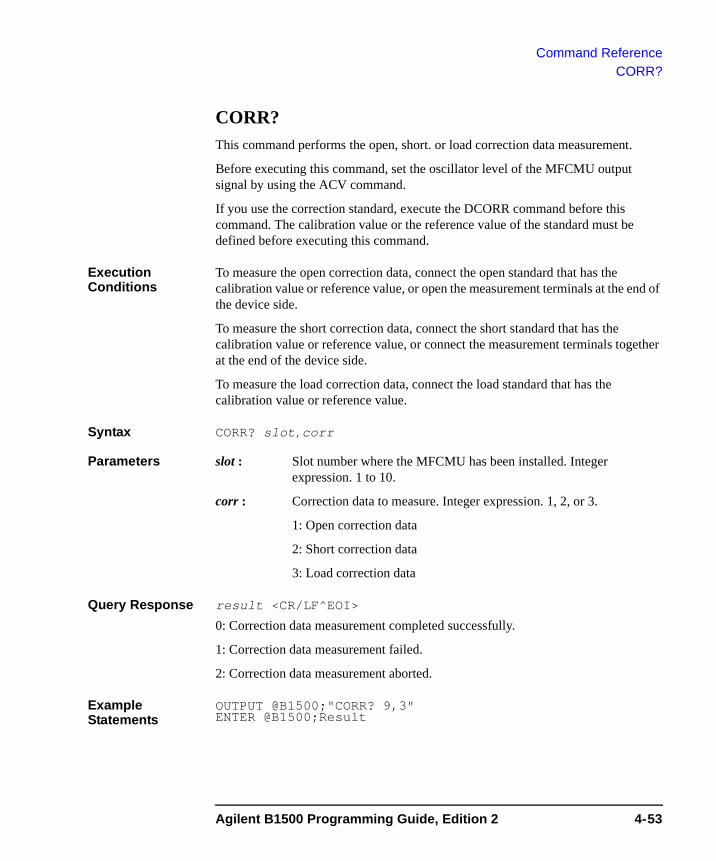
Command ReferenceCORR?
CORR?This command performs the open, short. or load correction data measurement.
Before executing this command, set the oscillator level of the MFCMU output signal by using the ACV command.
If you use the correction standard, execute the DCORR command before this command. The calibration value or the reference value of the standard must be defined before executing this command.
Execution Conditions
To measure the open correction data, connect the open standard that has the calibration value or reference value, or open the measurement terminals at the end of the device side.
To measure the short correction data, connect the short standard that has the calibration value or reference value, or connect the measurement terminals together at the end of the device side.
To measure the load correction data, connect the load standard that has the calibration value or reference value.
Syntax CORR? slot,corr
Parameters slot : Slot number where the MFCMU has been installed. Integer expression. 1 to 10.
corr : Correction data to measure. Integer expression. 1, 2, or 3.
1: Open correction data
2: Short correction data
3: Load correction data
Query Response result <CR/LF^EOI>
0: Correction data measurement completed successfully.
1: Correction data measurement failed.
2: Correction data measurement aborted.
Example Statements
OUTPUT @B1500;"CORR? 9,3"ENTER @B1500;Result
Agilent B1500 Programming Guide, Edition 2 4-53

Command ReferenceCORRL
CORRLThis command disables the open/short/load correction function and adds the specified frequency to the frequency list for the correction data measurement. The correction data will be invalid after this command.
Syntax CORRL slot,freq
Parameters slot : Slot number where the MFCMU has been installed. Integer expression. 1 to 10.
freq : Frequency to be added. Numeric expression. in Hz.
Example Statements
OUTPUT @B1500;"CORRL 9,3000000"
CORRL?This command returns the frequency stored in the frequency list for the correction data measurement.
Syntax CORRL? slot[,index]
Parameters slot : Slot number where the MFCMU has been installed. Integer expression. 1 to 10.
index : Index number of the list. Integer expression.
Query Response • CORRL? slot returns:
number_of_frequencies <CR/LF^EOI>
This value is the number of frequencies stored in the list.
• CORRL? slot,index returns:
frequency <CR/LF^EOI>
This value is the frequency corresponding to the specified index.
Example Statements
OUTPUT @B1500;"CLCORR 9,2"OUTPUT @B1500;"CORRL? 9"ENTER @B1500;NumberOUTPUT @B1500;"CORRL? 9,4"ENTER @B1500;Freq
This example returns Number=12 and Freq=10000.
4-54 Agilent B1500 Programming Guide, Edition 2
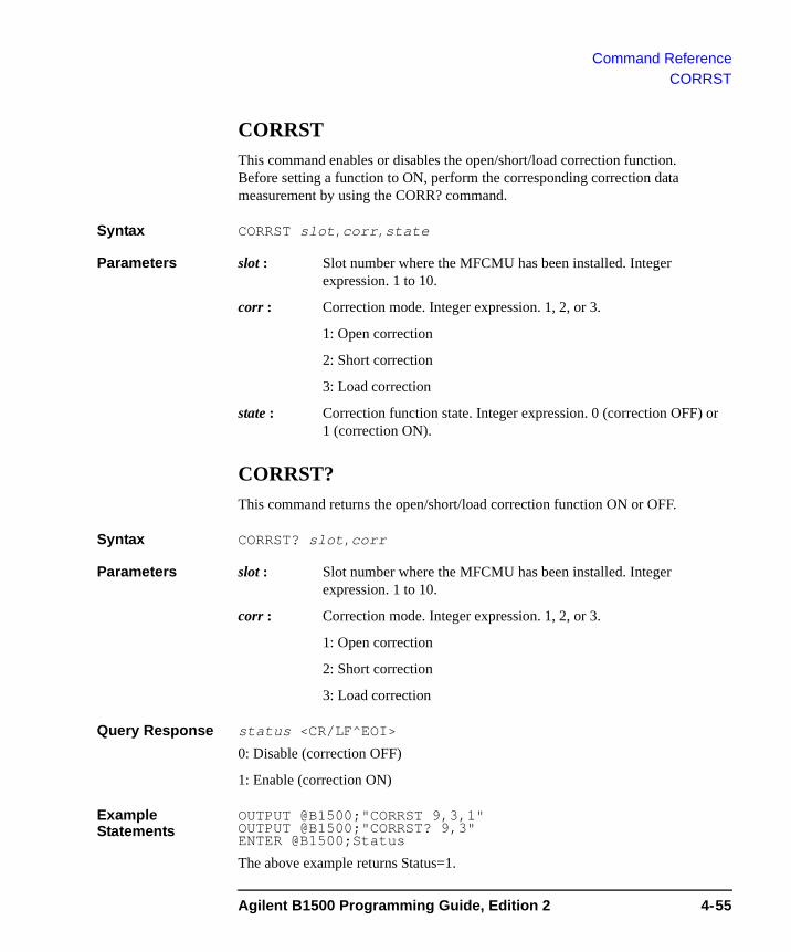
Command ReferenceCORRST
CORRSTThis command enables or disables the open/short/load correction function. Before setting a function to ON, perform the corresponding correction data measurement by using the CORR? command.
Syntax CORRST slot,corr,state
Parameters slot : Slot number where the MFCMU has been installed. Integer expression. 1 to 10.
corr : Correction mode. Integer expression. 1, 2, or 3.
1: Open correction
2: Short correction
3: Load correction
state : Correction function state. Integer expression. 0 (correction OFF) or 1 (correction ON).
CORRST?This command returns the open/short/load correction function ON or OFF.
Syntax CORRST? slot,corr
Parameters slot : Slot number where the MFCMU has been installed. Integer expression. 1 to 10.
corr : Correction mode. Integer expression. 1, 2, or 3.
1: Open correction
2: Short correction
3: Load correction
Query Response status <CR/LF^EOI>
0: Disable (correction OFF)
1: Enable (correction ON)
Example Statements
OUTPUT @B1500;"CORRST 9,3,1"OUTPUT @B1500;"CORRST? 9,3"ENTER @B1500;Status
The above example returns Status=1.
Agilent B1500 Programming Guide, Edition 2 4-55
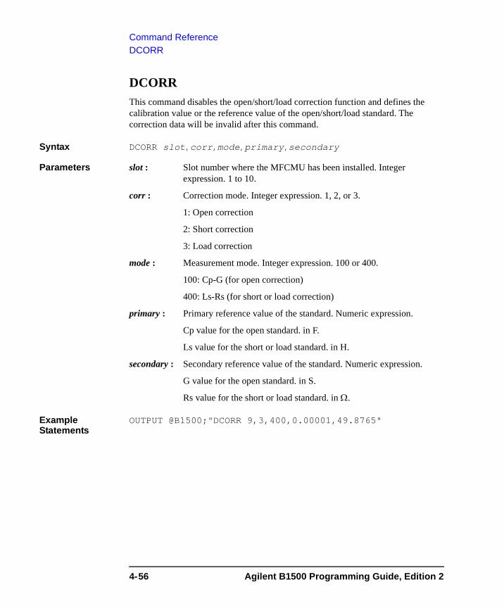
Command ReferenceDCORR
DCORRThis command disables the open/short/load correction function and defines the calibration value or the reference value of the open/short/load standard. The correction data will be invalid after this command.
Syntax DCORR slot,corr,mode,primary,secondary
Parameters slot : Slot number where the MFCMU has been installed. Integer expression. 1 to 10.
corr : Correction mode. Integer expression. 1, 2, or 3.
1: Open correction
2: Short correction
3: Load correction
mode : Measurement mode. Integer expression. 100 or 400.
100: Cp-G (for open correction)
400: Ls-Rs (for short or load correction)
primary : Primary reference value of the standard. Numeric expression.
Cp value for the open standard. in F.
Ls value for the short or load standard. in H.
secondary : Secondary reference value of the standard. Numeric expression.
G value for the open standard. in S.
Rs value for the short or load standard. in Ω.
Example Statements
OUTPUT @B1500;"DCORR 9,3,400,0.00001,49.8765"
4-56 Agilent B1500 Programming Guide, Edition 2
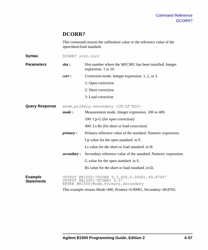
Command ReferenceDCORR?
DCORR?This command returns the calibration value or the reference value of the open/short/load standard.
Syntax DCORR? slot,corr
Parameters slot : Slot number where the MFCMU has been installed. Integer expression. 1 to 10.
corr : Correction mode. Integer expression. 1, 2, or 3.
1: Open correction
2: Short correction
3: Load correction
Query Response mode,primary,secondary <CR/LF^EOI>
mode : Measurement mode. Integer expression. 100 or 400.
100: Cp-G (for open correction)
400: Ls-Rs (for short or load correction)
primary : Primary reference value of the standard. Numeric expression.
Cp value for the open standard. in F.
Ls value for the short or load standard. in H.
secondary : Secondary reference value of the standard. Numeric expression.
G value for the open standard. in S.
Rs value for the short or load standard. in Ω.
Example Statements
OUTPUT @B1500;"DCORR 9,3,400,0.00001,49.8765"OUTPUT @B1500;"DCORR? 9,3"ENTER @B1500;Mode,Primary,Secondary
This example returns Mode=400, Priamry=0.00001, Secondary=49.8765.
Agilent B1500 Programming Guide, Edition 2 4-57
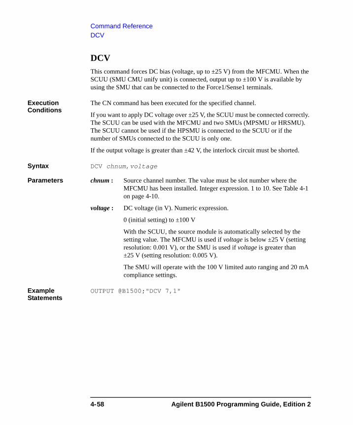
Command ReferenceDCV
DCVThis command forces DC bias (voltage, up to ±25 V) from the MFCMU. When the SCUU (SMU CMU unify unit) is connected, output up to ±100 V is available by using the SMU that can be connected to the Force1/Sense1 terminals.
Execution Conditions
The CN command has been executed for the specified channel.
If you want to apply DC voltage over ±25 V, the SCUU must be connected correctly. The SCUU can be used with the MFCMU and two SMUs (MPSMU or HRSMU). The SCUU cannot be used if the HPSMU is connected to the SCUU or if the number of SMUs connected to the SCUU is only one.
If the output voltage is greater than ±42 V, the interlock circuit must be shorted.
Syntax DCV chnum,voltage
Parameters chnum : Source channel number. The value must be slot number where the MFCMU has been installed. Integer expression. 1 to 10. See Table 4-1 on page 4-10.
voltage : DC voltage (in V). Numeric expression.
0 (initial setting) to ±100 V
With the SCUU, the source module is automatically selected by the setting value. The MFCMU is used if voltage is below ±25 V (setting resolution: 0.001 V), or the SMU is used if voltage is greater than ±25 V (setting resolution: 0.005 V).
The SMU will operate with the 100 V limited auto ranging and 20 mA compliance settings.
Example Statements
OUTPUT @B1500;"DCV 7,1"
4-58 Agilent B1500 Programming Guide, Edition 2

Command ReferenceDI
DIThe DI command forces DC current from the specified SMU.
Execution Conditions
The CN command has been executed for the specified channel.
If Vcomp value is greater than ±42 V, the interlock circuit must be shorted.
Syntax DI chnum,irange,current[,Vcomp[,comp_polarity[,vrange]]]
Parameters chnum : Source channel number. The value must be slot number where the SMU has been installed. Integer expression. 1 to 10. See Table 4-1 on page 4-10.
irange : Ranging type for current output. Integer expression. The output range will be set to the minimum range that covers current value. For the limited auto ranging, the instrument never uses the range less than the specified range. See Table 4-5 on page 4-13.
current : Output current value (in A). Numeric expression. See Table 4-7 on page 4-15.
0 to ±0.1 for MPSMU/HRSMU, or 0 to ±1 for HPSMU
Vcomp : Voltage compliance value (in V). Numeric expression. See Table 4-7 on page 4-15. If you do not specify this parameter, Vcomp is set to the previous setting.
comp_ polarity : Polarity of voltage compliance. Integer expression.
0: Auto mode (default setting). The compliance polarity is automatically set to the same polarity as current, regardless of the specified Vcomp. If current=0 A, the polarity is set to positive.
1: Manual mode. Uses the polarity of Vcomp you specified.
vrange : Voltage compliance ranging type. Integer expression. The compliance range will be set to the minimum range that covers Vcomp value. For the limited auto ranging, the instrument never uses the range less than the specified range. See Table 4-4 on page 4-13.
Example Statements
OUTPUT @B1500;"DI 1,0,1E-6"
OUTPUT @B1500;"DI 3,14,5E-7,20,0,0"
Agilent B1500 Programming Guide, Edition 2 4-59
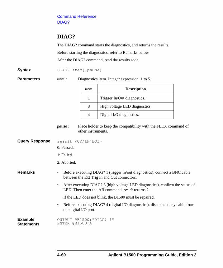
Command ReferenceDIAG?
DIAG? The DIAG? command starts the diagnostics, and returns the results.
Before starting the diagnostics, refer to Remarks below.
After the DIAG? command, read the results soon.
Syntax DIAG? item[,pause]
Parameters item : Diagnostics item. Integer expression. 1 to 5.
pause : Place holder to keep the compatibility with the FLEX command of other instruments.
Query Response result <CR/LF^EOI>
0: Passed.
1: Failed.
2: Aborted.
Remarks • Before executing DIAG? 1 (trigger in/out diagnostics), connect a BNC cable between the Ext Trig In and Out connectors.
• After executing DIAG? 3 (high voltage LED diagnostics), confirm the status of LED. Then enter the AB command. result returns 2.
If the LED does not blink, the B1500 must be repaired.
• Before executing DIAG? 4 (digital I/O diagnostics), disconnect any cable from the digital I/O port.
Example Statements
OUTPUT @B1500;"DIAG? 1" ENTER @B1500;A
item Description
1 Trigger In/Out diagnostics.
3 High voltage LED diagnostics.
4 Digital I/O diagnostics.
4-60 Agilent B1500 Programming Guide, Edition 2
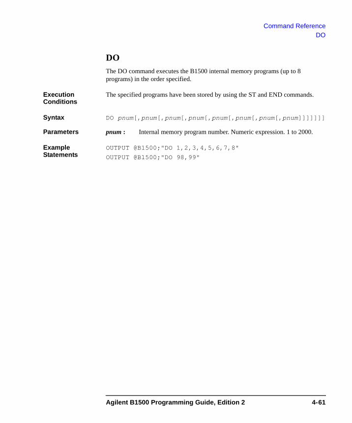
Command ReferenceDO
DO The DO command executes the B1500 internal memory programs (up to 8 programs) in the order specified.
Execution Conditions
The specified programs have been stored by using the ST and END commands.
Syntax DO pnum[,pnum[,pnum[,pnum[,pnum[,pnum[,pnum[,pnum]]]]]]]
Parameters pnum : Internal memory program number. Numeric expression. 1 to 2000.
Example Statements
OUTPUT @B1500;"DO 1,2,3,4,5,6,7,8"
OUTPUT @B1500;"DO 98,99"
Agilent B1500 Programming Guide, Edition 2 4-61

Command ReferenceDV
DV The DV command forces DC voltage from the specified SMU.
Execution Conditions
The CN command has been executed for the specified channel.
If the output voltage is greater than ±42 V, the interlock circuit must be shorted.
Syntax DV chnum,vrange,voltage[,Icomp[,comp_polarity[,irange]]
Parameters chnum : Source channel number. The value must be slot number where the SMU has been installed. Integer expression. 1 to 10. See Table 4-1 on page 4-10.
vrange : Ranging type for voltage output. Integer expression. The output range will be set to the minimum range that covers voltage value. For the limited auto ranging, the instrument never uses the range less than the specified range. See Table 4-4 on page 4-13.
voltage : Output voltage value (in V). Numeric expression. See Table 4-6 on page 4-14.
0 to ±100 for MPSMU/HRSMU, or 0 to ±200 for HPSMU
Icomp : Current compliance value (in A). Numeric expression. See Table 4-6 on page 4-14. If you do not set Icomp, the previous value is used. 0 A is not allowed for Icomp.
comp_ polarity : Polarity of current compliance. Integer expression.
0: Auto mode (default setting). The compliance polarity is automatically set to the same polarity as voltage, regardless of the specified Icomp. If voltage=0 V, the polarity is set to positive.
1: Manual mode. Uses the polarity of Icomp you specified.
irange : Current compliance ranging type. Integer expression. The compliance range will be set to the minimum range that covers Icomp value. For the limited auto ranging, the instrument never uses the range less than the specified range. See Table 4-5 on page 4-13.
Example Statements
OUTPUT @B1500;"DV 1,0,20,1E-6,0,15"
OUTPUT @B1500;"DV 2,12,10"
4-62 Agilent B1500 Programming Guide, Edition 2
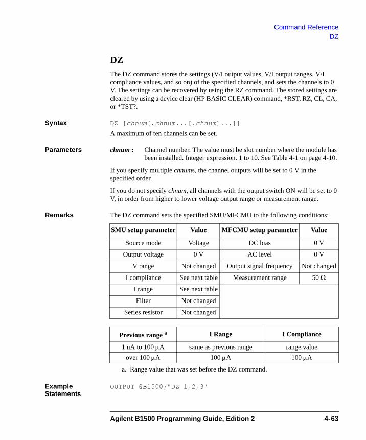
Command ReferenceDZ
DZ The DZ command stores the settings (V/I output values, V/I output ranges, V/I compliance values, and so on) of the specified channels, and sets the channels to 0 V. The settings can be recovered by using the RZ command. The stored settings are cleared by using a device clear (HP BASIC CLEAR) command, *RST, RZ, CL, CA, or *TST?.
Syntax DZ [chnum[,chnum...[,chnum]...]]
A maximum of ten channels can be set.
Parameters chnum : Channel number. The value must be slot number where the module has been installed. Integer expression. 1 to 10. See Table 4-1 on page 4-10.
If you specify multiple chnums, the channel outputs will be set to 0 V in the specified order.
If you do not specify chnum, all channels with the output switch ON will be set to 0 V, in order from higher to lower voltage output range or measurement range.
Remarks The DZ command sets the specified SMU/MFCMU to the following conditions:
Example Statements
OUTPUT @B1500;"DZ 1,2,3"
SMU setup parameter Value MFCMU setup parameter Value
Source mode Voltage DC bias 0 V
Output voltage 0 V AC level 0 V
V range Not changed Output signal frequency Not changed
I compliance See next table Measurement range 50 Ω
I range See next table
Filter Not changed
Series resistor Not changed
Previous range a
a. Range value that was set before the DZ command.
I Range I Compliance
1 nA to 100 μA same as previous range range valueover 100 μA 100 μA 100 μA
Agilent B1500 Programming Guide, Edition 2 4-63
Command ReferenceEMG?
EMG?The EMG? query command returns error message corresponding to the specified error code.
Syntax EMG? errcode
Parameters errcode : Error code returned by the ERR? command. Numeric expression.
Query Response Error message <CR/LF^EOI>
For the error codes and error messages, refer to Chapter 5, “Error Messages.”
Example Statements
OUTPUT @B1500;"EMG? 100" ENTER @B1500;A$
END The END command is used with the ST command to store a program in the internal program memory. See “ST” on page 4-128.
Syntax END
Example Statements
OUTPUT @B1500;"ST1;CN1;DV1,0,5,1E-4;TI1,0;CL1" OUTPUT @B1500;"END"
4-64 Agilent B1500 Programming Guide, Edition 2
Command ReferenceERC
ERCThe ERC command changes the output status of the digital I/O port. This command does not change the status of the trigger ports and the input ports set by the ERM command.
The *RST command or the device clear sets the digital I/O port (total 16 paths) to the output port, and sets the port output level to TTL high.
Syntax ERC mode,value[,rule]
Parameters mode : Control mode. Integer expression. Set mode to 2.
2: Controls the digital I/O port.
If you set 1 that is effective for the Agilent 4142B, an error occurs.
value : Decimal value of the output status bit pattern. Integer expression. 0 to 65535. The bit pattern must comply with the following rule:
Bit value 0: TTL high level (approx. 2.4 V)
Bit value 1: TTL low level (approx. 0.8 V)
rule : Place holder to keep the same syntax as the ERC command of the Agilent 4142B. Input value is ignored.
Example Statements
If you want to set TTL low level for the output ports of the digital I/O port bit 0 to 7, enter the following command.
OUTPUT @B1500;"ERC 2,255"
where the decimal value 255 means binary bit pattern 0000000011111111. This command does not change the status of the trigger ports and the input ports.
See Also “ERM” and “ERS?”
Agilent B1500 Programming Guide, Edition 2 4-65
Command ReferenceERM
ERMThe ERM command changes the input/output assignments of the digital I/O port (total 16 paths). This command does not change the trigger port assignments and settings.
The *RST command or the device clear sets the digital I/O port to the output port, and sets the port output level to TTL high.
Syntax ERM iport
Parameters iport : Decimal value of the port setting. Integer expression. 0 to 65535.
The setting of each port must be designated by 0 or 1 that has the following meaning:
0: Output port
1: Input port
Example Statements
If you want to use the non-trigger ports of the digital I/O ports 0 to 7 as the input port, enter the following statement.
OUTPUT @B1500;"ERM 255"
where the decimal value 255 means binary bit pattern 0000000011111111.
Remarks The ERM command sets the port level to TTL high for all ports where the port assignment is changed from output to input or from input to output.
The ERM command does not change the port assignment of the trigger ports.
See Also “ERS?”
4-66 Agilent B1500 Programming Guide, Edition 2

Command ReferenceERR?
ERR? The ERR? query command returns error codes from the B1500 error register to the output data buffer (query buffer).
This command clears the error register.
Syntax ERR? [mode]
Parameters mode : Error code output mode. Integer expression. 0 (default setting) or 1.
0: Returns up to four error codes in order from their occurrence.
1: Returns one error code.
If you do not specify mode, the ERR? command returns four error codes (same as mode=0).
Query Response Error Code,Error Code,Error Code,Error Code <CR/LF^EOI>
or
Error Code <CR/LF^EOI>
For the error codes, refer to Chapter 5, “Error Messages.” If no error occurred, Error Code is 0.
Example Statements
OUTPUT @B1500;"ERR?" ENTER @B1500;A$
OUTPUT @B1500;"ERR? 1" ENTER @B1500;A
Agilent B1500 Programming Guide, Edition 2 4-67
Command ReferenceERS?
ERS?The ERS? command returns the status of the digital I/O port (16 paths).
Syntax ERS?
Query Response pattern <CR/LF^EOI>
pattern returns the decimal value of the port status.
The status of each port is designated by 0 or 1 that has the following meaning:
0: TTL high level (approx. 2.4 V)
1: TTL low level (approx. 0.8 V)
Example Statements
OUTPUT @B1500;"ERS?"ENTER @B1500;APRINT "Port Status=";A
For example, 255 (0000000011111111) is returned when the port 0 to 7 have been set to the TTL low level and the port 8 to 15 have been set to the TTL high level.
See Also “ERM”
4-68 Agilent B1500 Programming Guide, Edition 2
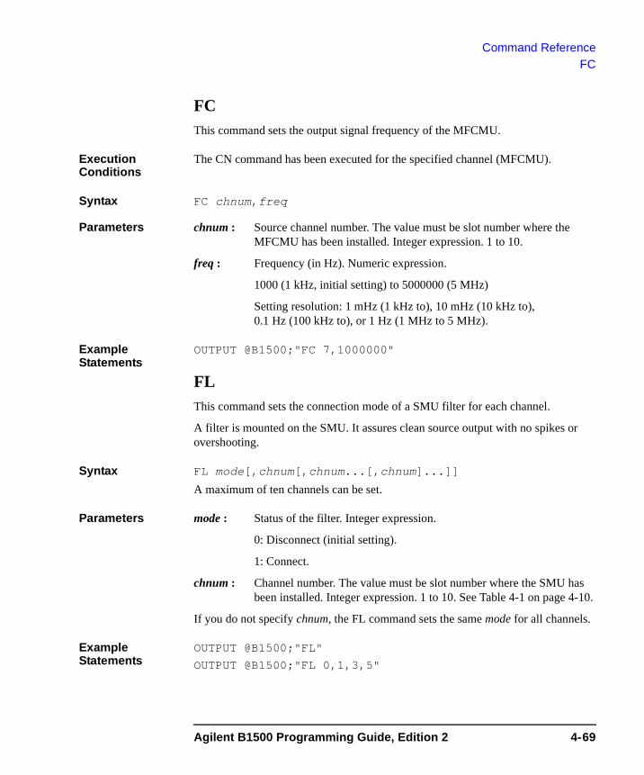
Command ReferenceFC
FCThis command sets the output signal frequency of the MFCMU.
Execution Conditions
The CN command has been executed for the specified channel (MFCMU).
Syntax FC chnum,freq
Parameters chnum : Source channel number. The value must be slot number where the MFCMU has been installed. Integer expression. 1 to 10.
freq : Frequency (in Hz). Numeric expression.
1000 (1 kHz, initial setting) to 5000000 (5 MHz)
Setting resolution: 1 mHz (1 kHz to), 10 mHz (10 kHz to), 0.1 Hz (100 kHz to), or 1 Hz (1 MHz to 5 MHz).
Example Statements
OUTPUT @B1500;"FC 7,1000000"
FL This command sets the connection mode of a SMU filter for each channel.
A filter is mounted on the SMU. It assures clean source output with no spikes or overshooting.
Syntax FL mode[,chnum[,chnum...[,chnum]...]]
A maximum of ten channels can be set.
Parameters mode : Status of the filter. Integer expression.
0: Disconnect (initial setting).
1: Connect.
chnum : Channel number. The value must be slot number where the SMU has been installed. Integer expression. 1 to 10. See Table 4-1 on page 4-10.
If you do not specify chnum, the FL command sets the same mode for all channels.
Example Statements
OUTPUT @B1500;"FL"
OUTPUT @B1500;"FL 0,1,3,5"
Agilent B1500 Programming Guide, Edition 2 4-69

Command ReferenceFMT
FMT This command clears the B1500 output data buffer, and specifies the data output format. For details about data output format, see “Data Output Format” on page 1-23. Without this command, the data output format is same as the format by the FMT1,0 command.
Query command output data is always stored in the query buffer in ASCII format, regardless of this command.
NOTE Multi command statement is not allowed for this command.
Syntax FMT format[,mode]
Parameters format : Data output format. Integer expression. 1 to 5, 11 to 15, 21, 22, or 25. See Table 4-13.
mode : Data output mode. Integer expression. 0 to 10. See Table 4-12. Without setting the mode value, only the measurement data is returned.
For the sampling measurement, the sampling point is returned when mode<>0 is set.
Example Statements
OUTPUT @B1500;"FMT 1"
OUTPUT @B1500;"FMT 2,1"
Table 4-12 FMT mode parameter
mode Source data returned with measurement data
0 None (default setting). Only the measurement data is returned.
1 Data of the primary sweep source set by the WI/WV/PWI/PWV/ WDCV command.
2 Data of the synchronous sweep source set by the WSI/WSV command.
2 to 10 For the multi channel sweep measurement:
Data of the synchronous sweep source set by the WNX command. The mode value must be the sweep source number (2 to 10) you want to get data. For the sweep source number, refer to “WNX” on page 4-159.
4-70 Agilent B1500 Programming Guide, Edition 2
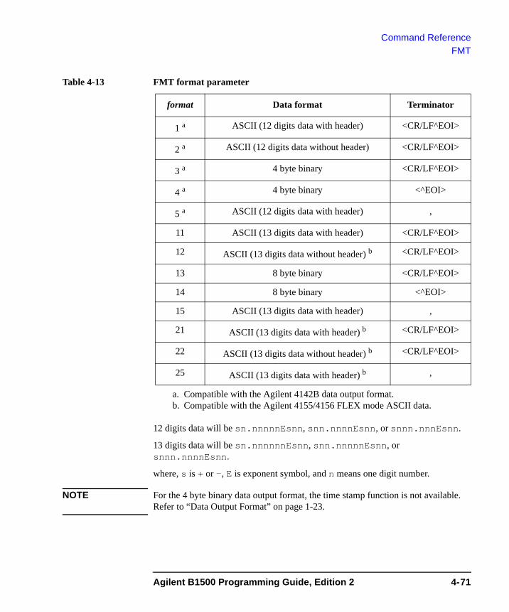
Command ReferenceFMT
Table 4-13 FMT format parameter
12 digits data will be sn.nnnnnEsnn, snn.nnnnEsnn, or snnn.nnnEsnn.
13 digits data will be sn.nnnnnnEsnn, snn.nnnnnEsnn, or snnn.nnnnEsnn.
where, s is + or -, E is exponent symbol, and n means one digit number.
NOTE For the 4 byte binary data output format, the time stamp function is not available. Refer to “Data Output Format” on page 1-23.
format Data format Terminator
1 a
a. Compatible with the Agilent 4142B data output format.
ASCII (12 digits data with header) <CR/LF^EOI>
2 a ASCII (12 digits data without header) <CR/LF^EOI>
3 a 4 byte binary <CR/LF^EOI>
4 a 4 byte binary <^EOI>
5 a ASCII (12 digits data with header) ,
11 ASCII (13 digits data with header) <CR/LF^EOI>
12 ASCII (13 digits data without header) b <CR/LF^EOI>
13 8 byte binary <CR/LF^EOI>
14 8 byte binary <^EOI>
15 ASCII (13 digits data with header) ,
21 ASCII (13 digits data with header) b
b. Compatible with the Agilent 4155/4156 FLEX mode ASCII data.
<CR/LF^EOI>
22 ASCII (13 digits data without header) b <CR/LF^EOI>
25 ASCII (13 digits data with header) b ,
Agilent B1500 Programming Guide, Edition 2 4-71
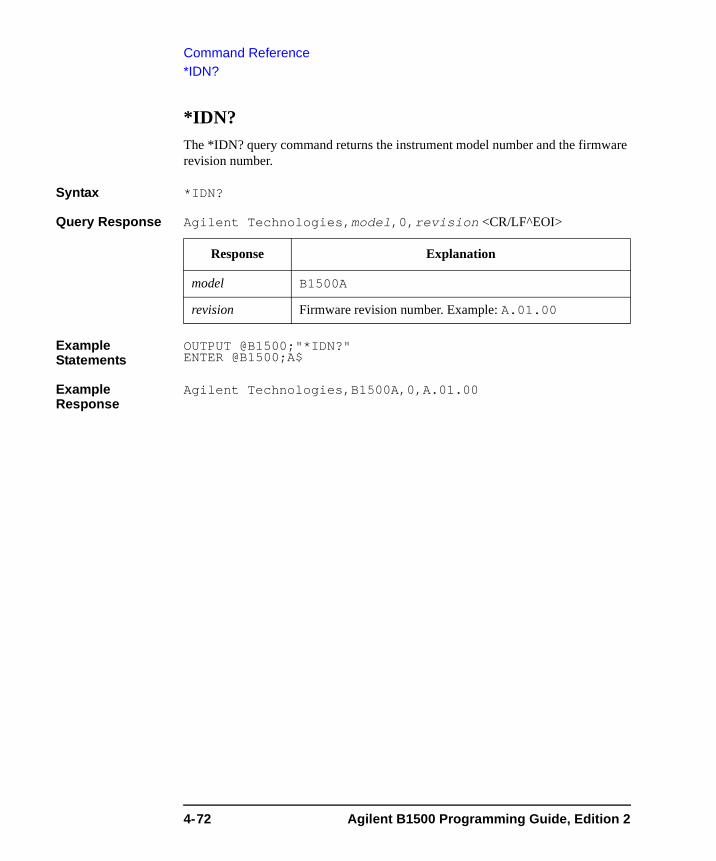
Command Reference*IDN?
*IDN? The *IDN? query command returns the instrument model number and the firmware revision number.
Syntax *IDN?
Query Response Agilent Technologies,model,0,revision <CR/LF^EOI>
Example Statements
OUTPUT @B1500;"*IDN?" ENTER @B1500;A$
Example Response
Agilent Technologies,B1500A,0,A.01.00
Response Explanation
model B1500A
revision Firmware revision number. Example: A.01.00
4-72 Agilent B1500 Programming Guide, Edition 2
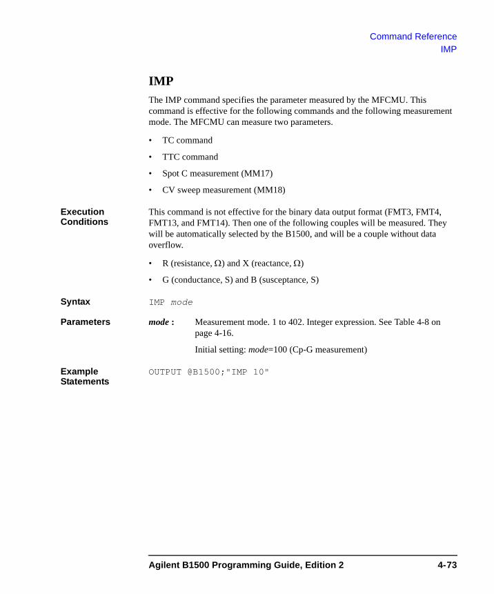
Command ReferenceIMP
IMPThe IMP command specifies the parameter measured by the MFCMU. This command is effective for the following commands and the following measurement mode. The MFCMU can measure two parameters.
• TC command
• TTC command
• Spot C measurement (MM17)
• CV sweep measurement (MM18)
Execution Conditions
This command is not effective for the binary data output format (FMT3, FMT4, FMT13, and FMT14). Then one of the following couples will be measured. They will be automatically selected by the B1500, and will be a couple without data overflow.
• R (resistance, Ω) and X (reactance, Ω)
• G (conductance, S) and B (susceptance, S)
Syntax IMP mode
Parameters mode : Measurement mode. 1 to 402. Integer expression. See Table 4-8 on page 4-16.
Initial setting: mode=100 (Cp-G measurement)
Example Statements
OUTPUT @B1500;"IMP 10"
Agilent B1500 Programming Guide, Edition 2 4-73
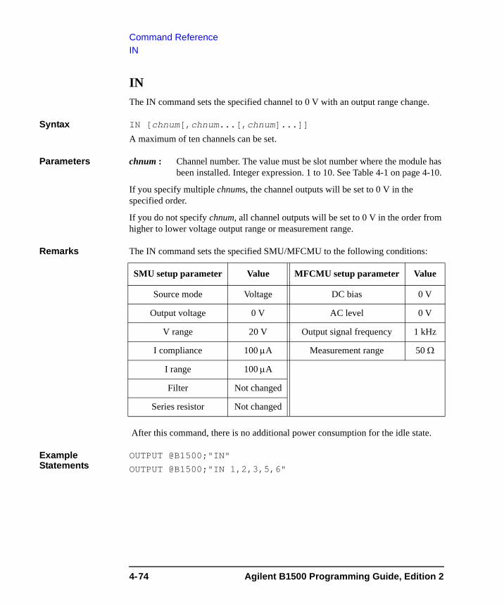
Command ReferenceIN
IN The IN command sets the specified channel to 0 V with an output range change.
Syntax IN [chnum[,chnum...[,chnum]...]]
A maximum of ten channels can be set.
Parameters chnum : Channel number. The value must be slot number where the module has been installed. Integer expression. 1 to 10. See Table 4-1 on page 4-10.
If you specify multiple chnums, the channel outputs will be set to 0 V in the specified order.
If you do not specify chnum, all channel outputs will be set to 0 V in the order from higher to lower voltage output range or measurement range.
Remarks The IN command sets the specified SMU/MFCMU to the following conditions:
After this command, there is no additional power consumption for the idle state.
Example Statements
OUTPUT @B1500;"IN"
OUTPUT @B1500;"IN 1,2,3,5,6"
SMU setup parameter Value MFCMU setup parameter Value
Source mode Voltage DC bias 0 V
Output voltage 0 V AC level 0 V
V range 20 V Output signal frequency 1 kHz
I compliance 100 μA Measurement range 50 Ω
I range 100 μA
Filter Not changed
Series resistor Not changed
4-74 Agilent B1500 Programming Guide, Edition 2
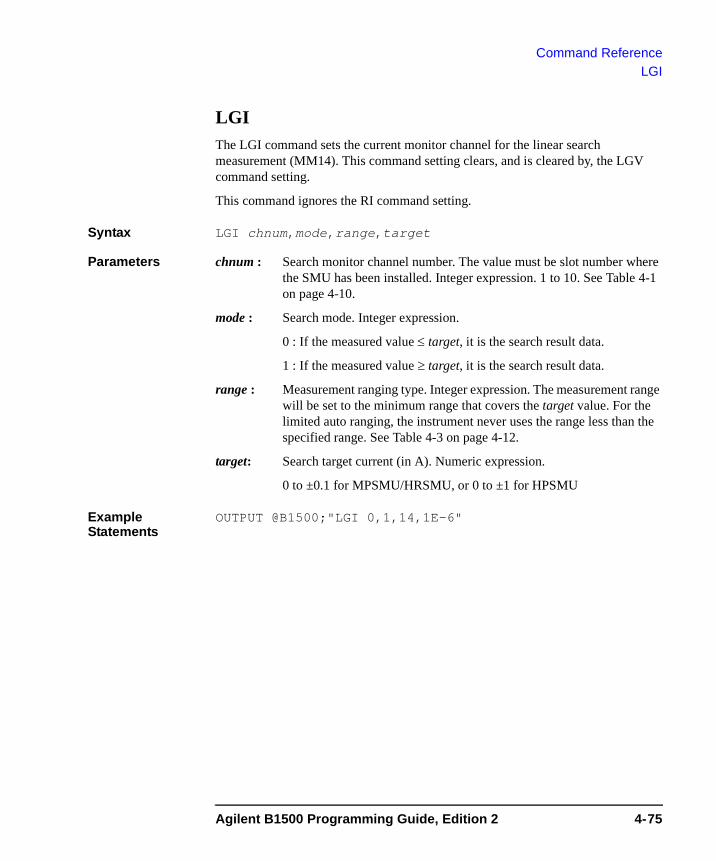
Command ReferenceLGI
LGIThe LGI command sets the current monitor channel for the linear search measurement (MM14). This command setting clears, and is cleared by, the LGV command setting.
This command ignores the RI command setting.
Syntax LGI chnum,mode,range,target
Parameters chnum : Search monitor channel number. The value must be slot number where the SMU has been installed. Integer expression. 1 to 10. See Table 4-1 on page 4-10.
mode : Search mode. Integer expression.
0 : If the measured value ≤ target, it is the search result data.
1 : If the measured value ≥ target, it is the search result data.
range : Measurement ranging type. Integer expression. The measurement range will be set to the minimum range that covers the target value. For the limited auto ranging, the instrument never uses the range less than the specified range. See Table 4-3 on page 4-12.
target: Search target current (in A). Numeric expression.
0 to ±0.1 for MPSMU/HRSMU, or 0 to ±1 for HPSMU
Example Statements
OUTPUT @B1500;"LGI 0,1,14,1E-6"
Agilent B1500 Programming Guide, Edition 2 4-75
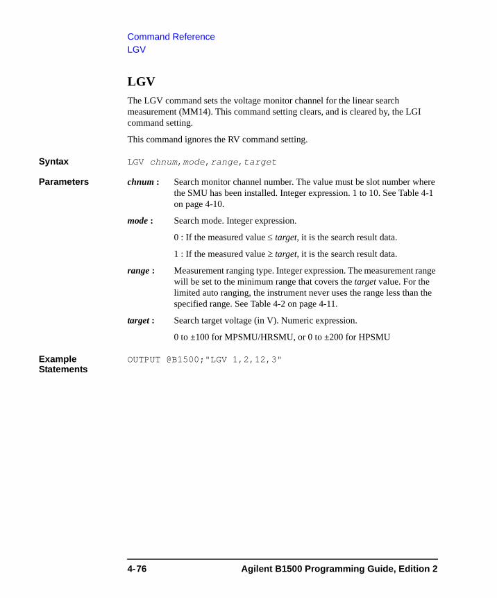
Command ReferenceLGV
LGV The LGV command sets the voltage monitor channel for the linear search measurement (MM14). This command setting clears, and is cleared by, the LGI command setting.
This command ignores the RV command setting.
Syntax LGV chnum,mode,range,target
Parameters chnum : Search monitor channel number. The value must be slot number where the SMU has been installed. Integer expression. 1 to 10. See Table 4-1 on page 4-10.
mode : Search mode. Integer expression.
0 : If the measured value ≤ target, it is the search result data.
1 : If the measured value ≥ target, it is the search result data.
range : Measurement ranging type. Integer expression. The measurement range will be set to the minimum range that covers the target value. For the limited auto ranging, the instrument never uses the range less than the specified range. See Table 4-2 on page 4-11.
target : Search target voltage (in V). Numeric expression.
0 to ±100 for MPSMU/HRSMU, or 0 to ±200 for HPSMU
Example Statements
OUTPUT @B1500;"LGV 1,2,12,3"
4-76 Agilent B1500 Programming Guide, Edition 2
Command ReferenceLMN
LMNThe LMN command enables or disables the data output of the AC voltage and DC voltage monitor values.
Execution Conditions
The measurement mode must be the spot C measurement mode (MM17) or the CV sweep measurement mode (MM18).
Syntax LMN mode
Parameters mode : Data output mode. Integer expression. 0 or 1.
1: Disables the data output. Initial setting.
2: Enables the data output.
Example Statements
OUTPUT @B1500;"LMN 1"
Agilent B1500 Programming Guide, Edition 2 4-77
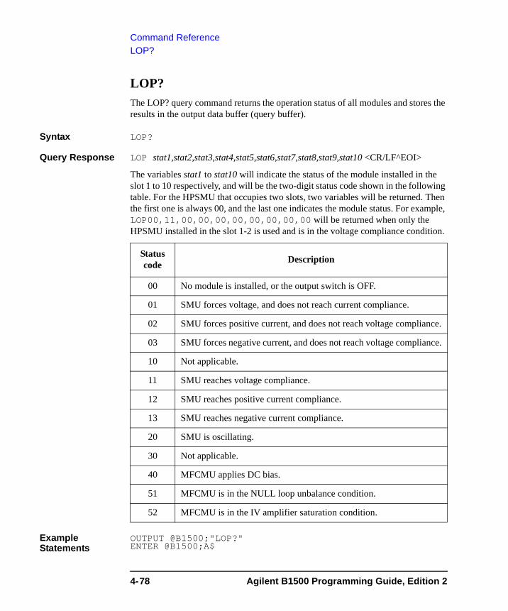
Command ReferenceLOP?
LOP? The LOP? query command returns the operation status of all modules and stores the results in the output data buffer (query buffer).
Syntax LOP?
Query Response LOP stat1,stat2,stat3,stat4,stat5,stat6,stat7,stat8,stat9,stat10 <CR/LF^EOI>
The variables stat1 to stat10 will indicate the status of the module installed in the slot 1 to 10 respectively, and will be the two-digit status code shown in the following table. For the HPSMU that occupies two slots, two variables will be returned. Then the first one is always 00, and the last one indicates the module status. For example, LOP00,11,00,00,00,00,00,00,00,00 will be returned when only the HPSMU installed in the slot 1-2 is used and is in the voltage compliance condition.
Example Statements
OUTPUT @B1500;"LOP?" ENTER @B1500;A$
Status code Description
00 No module is installed, or the output switch is OFF.
01 SMU forces voltage, and does not reach current compliance.
02 SMU forces positive current, and does not reach voltage compliance.
03 SMU forces negative current, and does not reach voltage compliance.
10 Not applicable.
11 SMU reaches voltage compliance.
12 SMU reaches positive current compliance.
13 SMU reaches negative current compliance.
20 SMU is oscillating.
30 Not applicable.
40 MFCMU applies DC bias.
51 MFCMU is in the NULL loop unbalance condition.
52 MFCMU is in the IV amplifier saturation condition.
4-78 Agilent B1500 Programming Guide, Edition 2
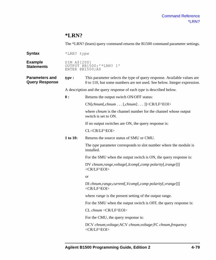
Command Reference*LRN?
*LRN? The *LRN? (learn) query command returns the B1500 command parameter settings.
Syntax *LRN? type
Example Statements
DIM A$[200]OUTPUT @B1500;"*LRN? 1" ENTER @B1500;A$
Parameters and Query Response
type : This parameter selects the type of query response. Available values are 0 to 110, but some numbers are not used. See below. Integer expression.
A description and the query response of each type is described below.
0 : Returns the output switch ON/OFF status:
CN[chnum[,chnum . . . [,chnum] . . . ]]<CR/LF^EOI>
where chnum is the channel number for the channel whose output switch is set to ON.
If no output switches are ON, the query response is:
CL<CR/LF^EOI>
1 to 10: Returns the source status of SMU or CMU.
The type parameter corresponds to slot number where the module is installed.
For the SMU when the output switch is ON, the query response is:
DV chnum,range,voltage[,Icomp[,comp polarity[,irange]]]<CR/LF^EOI>
or
DI chnum,range,current[,Vcomp[,comp polarity[,vrange]]]<CR/LF^EOI>
where range is the present setting of the output range.
For the SMU when the output switch is OFF, the query response is:
CL chnum <CR/LF^EOI>
For the CMU, the query response is:
DCV chnum,voltage;ACV chnum,voltage;FC chnum,frequency<CR/LF^EOI>
Agilent B1500 Programming Guide, Edition 2 4-79
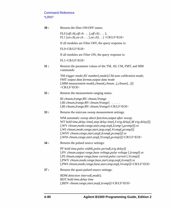
Command Reference*LRN?
30 : Returns the filter ON/OFF status:
FL0 [off ch[,off ch . . . [,off ch] . . . ];FL1 [on ch[,on ch . . . [,on ch] . . ] <CR/LF^EOI>
If all modules are Filter OFF, the query response is:
FL0<CR/LF^EOI>
If all modules are Filter ON, the query response is:
FL1<CR/LF^EOI>
31 : Returns the parameter values of the TM, AV, CM, FMT, and MM commands:
TM trigger mode;AV number[,mode];CM auto calibration mode; FMT output data format,output data mode [;MM measurement mode[,chnum[,chnum...[,chnum]...]]] <CR/LF^EOI>
32 : Returns the measurement ranging status:
RI chnum,Irange;RV chnum,Vrange[;RI chnum,Irange;RV chnum,Vrange] . . . . [;RI chnum,Irange;RV chnum,Vrange]<CR/LF^EOI>
33 : Returns the staircase sweep measurement settings:
WM automatic sweep abort function,output after sweep; WT hold time,delay time[,step delay time[,S trig delay[,M trig delay]]] [;WV chnum,mode,range,start,stop,nop[,Icomp [,pcomp]]] or [;WI chnum,mode,range,start,stop,nop[,Vcomp[,pcomp]]] [;WSV chnum,range,start,stop[,Icomp[,pcomp]]] or [;WSI chnum,range,start,stop[,Vcomp[,pcomp]]]<CR/LF^EOI>
34 : Returns the pulsed source settings:
PT hold time,pulse width[,pulse period[,trig delay]][;PV chnum,output range,base voltage,pulse voltage [,Icomp]] or [;PI chnum,output range,base current,pulse current [,Vcomp]] [;PWV chnum,mode,range,base,start,stop,nop[,Icomp]] or [;PWI chnum,mode,range,base,start,stop,nop[,Vcomp]]<CR/LF^EOI>
37 : Returns the quasi-pulsed source settings:
BDM detection interval[,mode];BDT hold time,delay time [;BDV chnum,range,start,stop[,Icomp]]<CR/LF^EOI>
4-80 Agilent B1500 Programming Guide, Edition 2

Command Reference*LRN?
38 : Returns the digital I/O port information:
ERM input pin;ERC2,value <CR/LF^EOI>
40 : Returns channel mapping information:
If multiple channel numbers are translated to another numbers.
ACH actual,program[;ACH actual,program] . . . .[;ACH actual,program]<CR/LF^EOI>
If no channel number is defined by the ACH command.
ACH<CR/LF^EOI>
46 : Returns SMU measurement operation mode settings:
CMM chnum,mode[;CMM chnum,mode] . . . .[;CMM chnum,mode]<CR/LF^EOI>
47 : Returns the sampling measurement settings:
MSC abort,post;MT h_bias,interval,number,h_base;ML mode[;MV chnum,range,base,output,comp] or [;MI chnum,range,base,output,comp]
:<CR/LF^EOI>
50 : Returns the linear search measurement settings:
LSM abort,post;LSTM hold,delay;LSVM mode[;LGI chnum,mode,Irange,Itarget] or [;LGV chnum,mode,Vrange,Vtarget][;LSV chnum,range,start,stop,step[,Icomp]] or [;LSI chnum,range,start,stop,step[,Vcomp]] [;LSSV chnum,polarity,offset[,Icomp]] or [;LSSI chnum,polarity,offset[,Vcomp]]<CR/LF^EOI>
51 : Returns the binary search measurement settings:
BSM mode,past;BST hold,delay;BSVM mode[;BGI chnum,mode,condition,Irange,Itarget] or [;BGV chnum,mode,condition,Vrange,Vtarget][;BSV chnum,range,start,stop[,Icomp]] or [;BSI chnum,range,start,stop[,Vcomp]] [;BSSV chnum,polarity,offset[,Icomp]] or [;BSSI chnum,polarity,offset[,Vcomp]]<CR/LF^EOI>
Agilent B1500 Programming Guide, Edition 2 4-81
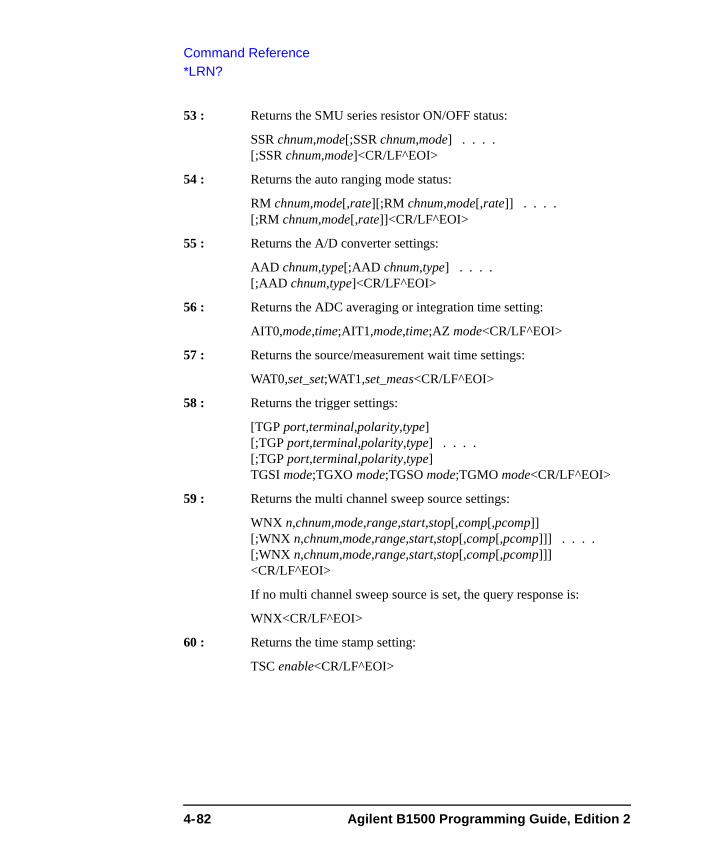
Command Reference*LRN?
53 : Returns the SMU series resistor ON/OFF status:
SSR chnum,mode[;SSR chnum,mode] . . . .[;SSR chnum,mode]<CR/LF^EOI>
54 : Returns the auto ranging mode status:
RM chnum,mode[,rate][;RM chnum,mode[,rate]] . . . .[;RM chnum,mode[,rate]]<CR/LF^EOI>
55 : Returns the A/D converter settings:
AAD chnum,type[;AAD chnum,type] . . . .[;AAD chnum,type]<CR/LF^EOI>
56 : Returns the ADC averaging or integration time setting:
AIT0,mode,time;AIT1,mode,time;AZ mode<CR/LF^EOI>
57 : Returns the source/measurement wait time settings:
WAT0,set_set;WAT1,set_meas<CR/LF^EOI>
58 : Returns the trigger settings:
[TGP port,terminal,polarity,type][;TGP port,terminal,polarity,type] . . . .[;TGP port,terminal,polarity,type]TGSI mode;TGXO mode;TGSO mode;TGMO mode<CR/LF^EOI>
59 : Returns the multi channel sweep source settings:
WNX n,chnum,mode,range,start,stop[,comp[,pcomp]][;WNX n,chnum,mode,range,start,stop[,comp[,pcomp]]] . . . .[;WNX n,chnum,mode,range,start,stop[,comp[,pcomp]]]<CR/LF^EOI>
If no multi channel sweep source is set, the query response is:
WNX<CR/LF^EOI>
60 : Returns the time stamp setting:
TSC enable<CR/LF^EOI>
4-82 Agilent B1500 Programming Guide, Edition 2
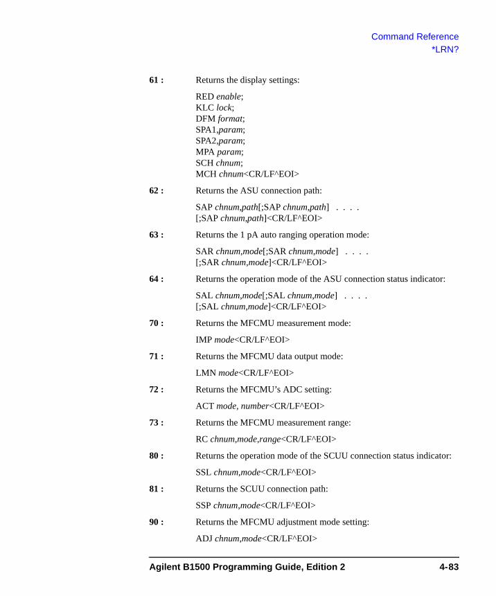
Command Reference*LRN?
61 : Returns the display settings:
RED enable;KLC lock;DFM format;SPA1,param;SPA2,param;MPA param;SCH chnum;MCH chnum<CR/LF^EOI>
62 : Returns the ASU connection path:
SAP chnum,path[;SAP chnum,path] . . . .[;SAP chnum,path]<CR/LF^EOI>
63 : Returns the 1 pA auto ranging operation mode:
SAR chnum,mode[;SAR chnum,mode] . . . .[;SAR chnum,mode]<CR/LF^EOI>
64 : Returns the operation mode of the ASU connection status indicator:
SAL chnum,mode[;SAL chnum,mode] . . . .[;SAL chnum,mode]<CR/LF^EOI>
70 : Returns the MFCMU measurement mode:
IMP mode<CR/LF^EOI>
71 : Returns the MFCMU data output mode:
LMN mode<CR/LF^EOI>
72 : Returns the MFCMU’s ADC setting:
ACT mode, number<CR/LF^EOI>
73 : Returns the MFCMU measurement range:
RC chnum,mode,range<CR/LF^EOI>
80 : Returns the operation mode of the SCUU connection status indicator:
SSL chnum,mode<CR/LF^EOI>
81 : Returns the SCUU connection path:
SSP chnum,mode<CR/LF^EOI>
90 : Returns the MFCMU adjustment mode setting:
ADJ chnum,mode<CR/LF^EOI>
Agilent B1500 Programming Guide, Edition 2 4-83

Command Reference*LRN?
100 : Returns the CV sweep measurement settings:
WMDCV abort function[,output after sweep]; WTDCV hold,delay[,step delay[,S trig delay[,M trig delay]]] [;WDCV chnum,mode,start,stop,nop]<CR/LF^EOI>
110 : Returns the parallel measurement mode setting:
PAD mode<CR/LF^EOI>
4-84 Agilent B1500 Programming Guide, Edition 2
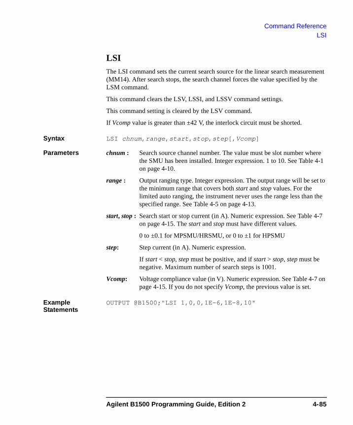
Command ReferenceLSI
LSI The LSI command sets the current search source for the linear search measurement (MM14). After search stops, the search channel forces the value specified by the LSM command.
This command clears the LSV, LSSI, and LSSV command settings.
This command setting is cleared by the LSV command.
If Vcomp value is greater than ±42 V, the interlock circuit must be shorted.
Syntax LSI chnum,range,start,stop,step[,Vcomp]
Parameters chnum : Search source channel number. The value must be slot number where the SMU has been installed. Integer expression. 1 to 10. See Table 4-1 on page 4-10.
range : Output ranging type. Integer expression. The output range will be set to the minimum range that covers both start and stop values. For the limited auto ranging, the instrument never uses the range less than the specified range. See Table 4-5 on page 4-13.
start, stop : Search start or stop current (in A). Numeric expression. See Table 4-7 on page 4-15. The start and stop must have different values.
0 to ±0.1 for MPSMU/HRSMU, or 0 to ±1 for HPSMU
step: Step current (in A). Numeric expression.
If start < stop, step must be positive, and if start > stop, step must be negative. Maximum number of search steps is 1001.
Vcomp: Voltage compliance value (in V). Numeric expression. See Table 4-7 on page 4-15. If you do not specify Vcomp, the previous value is set.
Example Statements
OUTPUT @B1500;"LSI 1,0,0,1E-6,1E-8,10"
Agilent B1500 Programming Guide, Edition 2 4-85
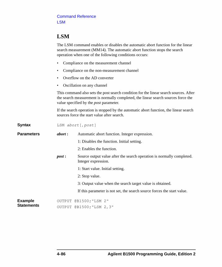
Command ReferenceLSM
LSMThe LSM command enables or disables the automatic abort function for the linear search measurement (MM14). The automatic abort function stops the search operation when one of the following conditions occurs:
• Compliance on the measurement channel
• Compliance on the non-measurement channel
• Overflow on the AD converter
• Oscillation on any channel
This command also sets the post search condition for the linear search sources. After the search measurement is normally completed, the linear search sources force the value specified by the post parameter.
If the search operation is stopped by the automatic abort function, the linear search sources force the start value after search.
Syntax LSM abort[,post]
Parameters abort : Automatic abort function. Integer expression.
1: Disables the function. Initial setting.
2: Enables the function.
post : Source output value after the search operation is normally completed. Integer expression.
1: Start value. Initial setting.
2: Stop value.
3: Output value when the search target value is obtained.
If this parameter is not set, the search source forces the start value.
Example Statements
OUTPUT @B1500;"LSM 2"
OUTPUT @B1500;"LSM 2,3"
4-86 Agilent B1500 Programming Guide, Edition 2
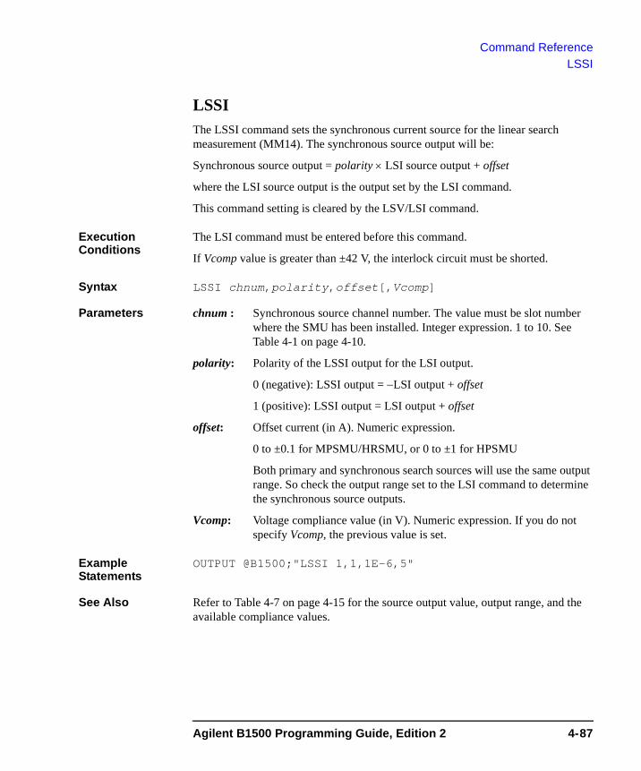
Command ReferenceLSSI
LSSI The LSSI command sets the synchronous current source for the linear search measurement (MM14). The synchronous source output will be:
Synchronous source output = polarity × LSI source output + offset
where the LSI source output is the output set by the LSI command.
This command setting is cleared by the LSV/LSI command.
Execution Conditions
The LSI command must be entered before this command.
If Vcomp value is greater than ±42 V, the interlock circuit must be shorted.
Syntax LSSI chnum,polarity,offset[,Vcomp]
Parameters chnum : Synchronous source channel number. The value must be slot number where the SMU has been installed. Integer expression. 1 to 10. See Table 4-1 on page 4-10.
polarity: Polarity of the LSSI output for the LSI output.
0 (negative): LSSI output = −LSI output + offset
1 (positive): LSSI output = LSI output + offset
offset: Offset current (in A). Numeric expression.
0 to ±0.1 for MPSMU/HRSMU, or 0 to ±1 for HPSMU
Both primary and synchronous search sources will use the same output range. So check the output range set to the LSI command to determine the synchronous source outputs.
Vcomp: Voltage compliance value (in V). Numeric expression. If you do not specify Vcomp, the previous value is set.
Example Statements
OUTPUT @B1500;"LSSI 1,1,1E-6,5"
See Also Refer to Table 4-7 on page 4-15 for the source output value, output range, and the available compliance values.
Agilent B1500 Programming Guide, Edition 2 4-87
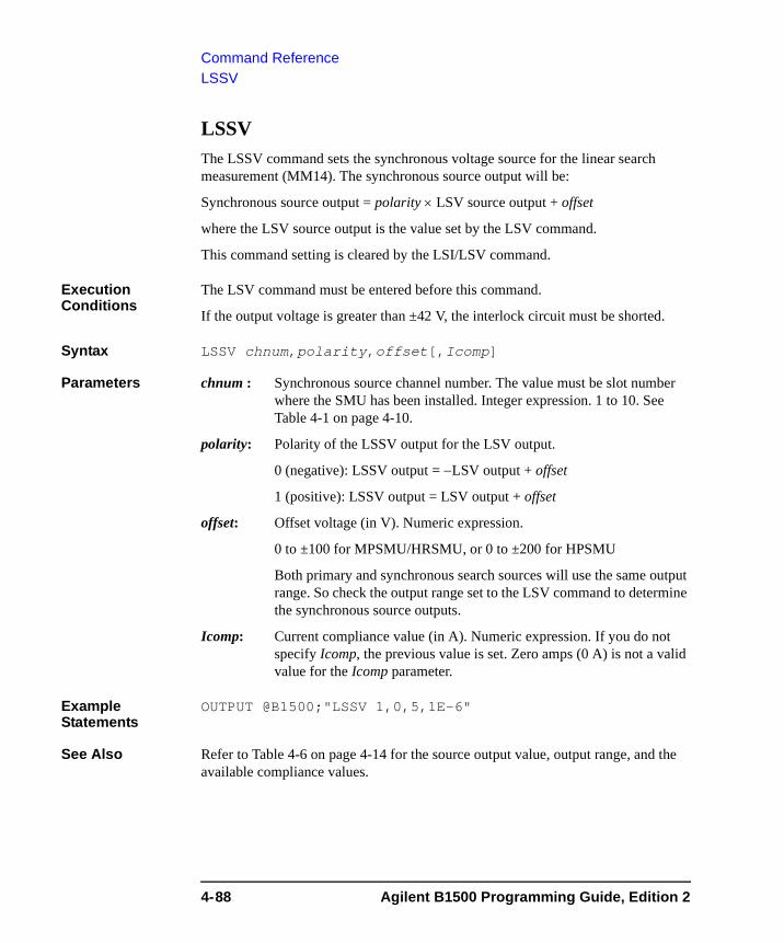
Command ReferenceLSSV
LSSV The LSSV command sets the synchronous voltage source for the linear search measurement (MM14). The synchronous source output will be:
Synchronous source output = polarity × LSV source output + offset
where the LSV source output is the value set by the LSV command.
This command setting is cleared by the LSI/LSV command.
Execution Conditions
The LSV command must be entered before this command.
If the output voltage is greater than ±42 V, the interlock circuit must be shorted.
Syntax LSSV chnum,polarity,offset[,Icomp]
Parameters chnum : Synchronous source channel number. The value must be slot number where the SMU has been installed. Integer expression. 1 to 10. See Table 4-1 on page 4-10.
polarity: Polarity of the LSSV output for the LSV output.
0 (negative): LSSV output = −LSV output + offset
1 (positive): LSSV output = LSV output + offset
offset: Offset voltage (in V). Numeric expression.
0 to ±100 for MPSMU/HRSMU, or 0 to ±200 for HPSMU
Both primary and synchronous search sources will use the same output range. So check the output range set to the LSV command to determine the synchronous source outputs.
Icomp: Current compliance value (in A). Numeric expression. If you do not specify Icomp, the previous value is set. Zero amps (0 A) is not a valid value for the Icomp parameter.
Example Statements
OUTPUT @B1500;"LSSV 1,0,5,1E-6"
See Also Refer to Table 4-6 on page 4-14 for the source output value, output range, and the available compliance values.
4-88 Agilent B1500 Programming Guide, Edition 2
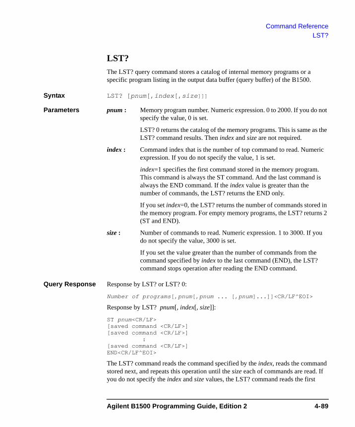
Command ReferenceLST?
LST? The LST? query command stores a catalog of internal memory programs or a specific program listing in the output data buffer (query buffer) of the B1500.
Syntax LST? [pnum[,index[,size]]]
Parameters pnum : Memory program number. Numeric expression. 0 to 2000. If you do not specify the value, 0 is set.
LST? 0 returns the catalog of the memory programs. This is same as the LST? command results. Then index and size are not required.
index : Command index that is the number of top command to read. Numeric expression. If you do not specify the value, 1 is set.
index=1 specifies the first command stored in the memory program. This command is always the ST command. And the last command is always the END command. If the index value is greater than the number of commands, the LST? returns the END only.
If you set index=0, the LST? returns the number of commands stored in the memory program. For empty memory programs, the LST? returns 2 (ST and END).
size : Number of commands to read. Numeric expression. 1 to 3000. If you do not specify the value, 3000 is set.
If you set the value greater than the number of commands from the command specified by index to the last command (END), the LST? command stops operation after reading the END command.
Query Response Response by LST? or LST? 0:
Number of programs[,pnum[,pnum ... [,pnum]...]]<CR/LF^EOI>
Response by LST? pnum[, index[, size]]:
ST pnum<CR/LF>[saved command <CR/LF>][saved command <CR/LF>]
:[saved command <CR/LF>]END<CR/LF^EOI>
The LST? command reads the command specified by the index, reads the command stored next, and repeats this operation until the size each of commands are read. If you do not specify the index and size values, the LST? command reads the first
Agilent B1500 Programming Guide, Edition 2 4-89
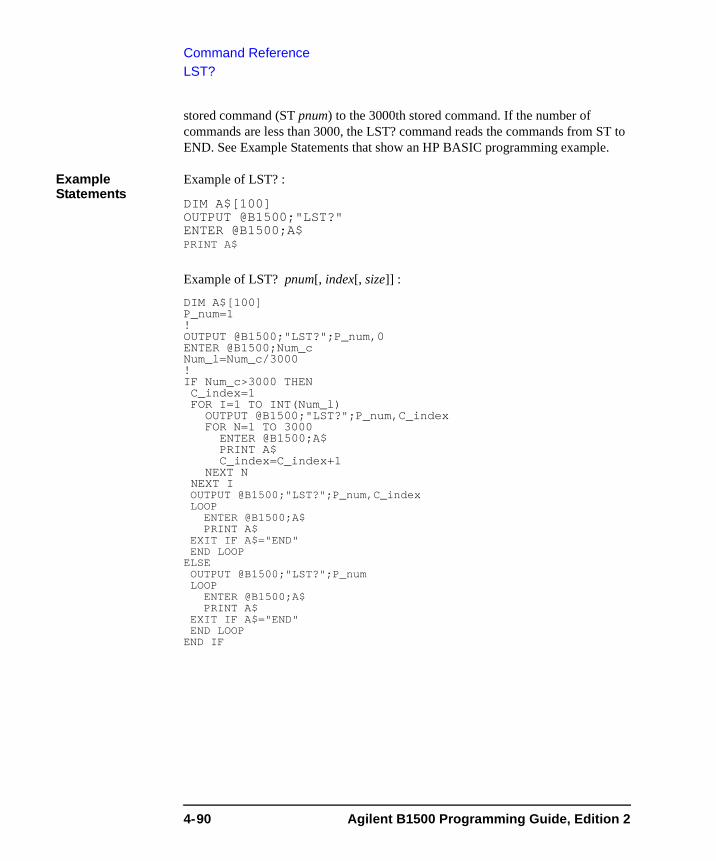
Command ReferenceLST?
stored command (ST pnum) to the 3000th stored command. If the number of commands are less than 3000, the LST? command reads the commands from ST to END. See Example Statements that show an HP BASIC programming example.
Example Statements
Example of LST? :
DIM A$[100]OUTPUT @B1500;"LST?"ENTER @B1500;A$PRINT A$
Example of LST? pnum[, index[, size]] :
DIM A$[100]P_num=1!OUTPUT @B1500;"LST?";P_num,0ENTER @B1500;Num_cNum_l=Num_c/3000!IF Num_c>3000 THENC_index=1FOR I=1 TO INT(Num_l)
OUTPUT @B1500;"LST?";P_num,C_indexFOR N=1 TO 3000
ENTER @B1500;A$PRINT A$C_index=C_index+1
NEXT NNEXT IOUTPUT @B1500;"LST?";P_num,C_indexLOOP
ENTER @B1500;A$PRINT A$
EXIT IF A$="END"END LOOPELSEOUTPUT @B1500;"LST?";P_numLOOP
ENTER @B1500;A$PRINT A$
EXIT IF A$="END"END LOOPEND IF
4-90 Agilent B1500 Programming Guide, Edition 2
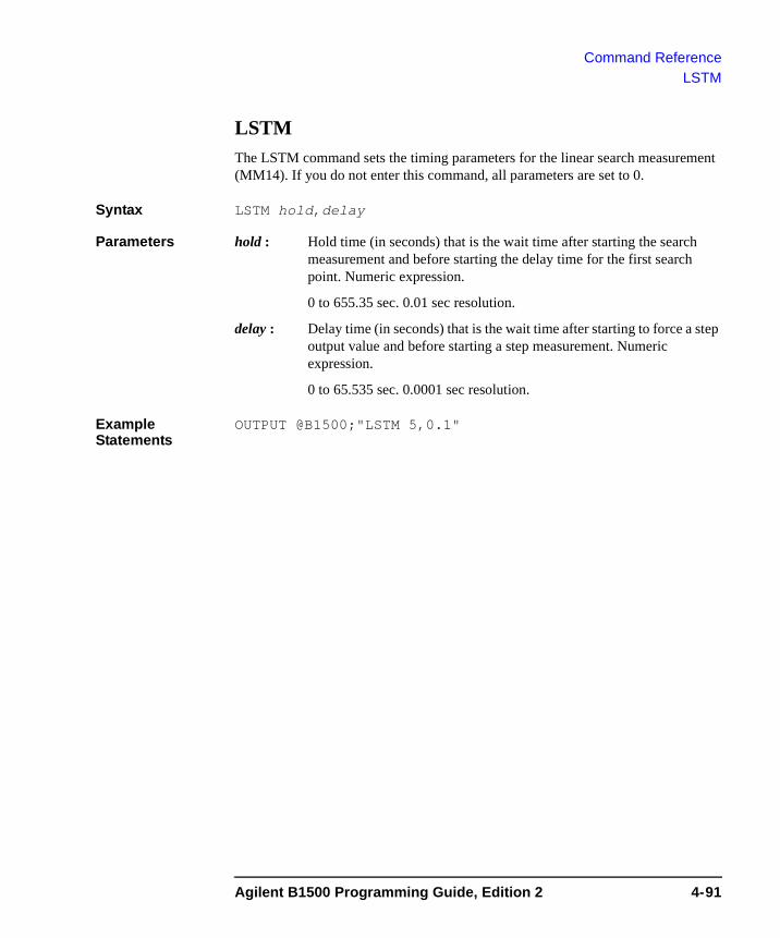
Command ReferenceLSTM
LSTMThe LSTM command sets the timing parameters for the linear search measurement (MM14). If you do not enter this command, all parameters are set to 0.
Syntax LSTM hold,delay
Parameters hold : Hold time (in seconds) that is the wait time after starting the search measurement and before starting the delay time for the first search point. Numeric expression.
0 to 655.35 sec. 0.01 sec resolution.
delay : Delay time (in seconds) that is the wait time after starting to force a step output value and before starting a step measurement. Numeric expression.
0 to 65.535 sec. 0.0001 sec resolution.
Example Statements
OUTPUT @B1500;"LSTM 5,0.1"
Agilent B1500 Programming Guide, Edition 2 4-91
Command ReferenceLSV
LSV The LSV command sets the voltage search source for the linear search measurement (MM14). After search stops, the search channel forces the value specified by the LSM command.
This command clears the LSI, LSSI, and LSSV command settings.
This command setting is cleared by the LSI command.
If the output voltage is greater than ±42 V, the interlock circuit must be shorted.
Syntax LSV chnum,range,start,stop,step[,Icomp]
Parameters chnum : Search source channel number. The value must be slot number where the SMU has been installed. Integer expression. 1 to 10. See Table 4-1 on page 4-10.
range : Output ranging type. Integer expression. The output range will be set to the minimum range that covers both start and stop values. Range changing may cause 0 V output in a moment. For the limited auto ranging, the instrument never uses the range less than the specified range. See Table 4-4 on page 4-13.
start, stop : Search start or stop voltage (in V). Numeric expression. See Table 4-6 on page 4-14. The start and stop parameters must have different values.
0 to ±100 for MPSMU/HRSMU,
0 to ±200 for HPSMU
step : Step voltage (in V). Numeric expression.
If start < stop, step must be positive, and if start > stop, step must be negative. Maximum number of search steps is 1001.
Icomp: Current compliance value (in A). Numeric expression. See Table 4-6 on page 4-14. If you do not specify Icomp, the previous value is set. Zero amps (0 A) is not allowed for Icomp.
Example Statements
OUTPUT @B1500;"LSV 1,0,0,20,.5,1E-6"
4-92 Agilent B1500 Programming Guide, Edition 2
Command ReferenceLSVM
LSVMThe LSVM command selects the data output mode for the linear search measurement (MM14).
Syntax LSVM mode
Parameters mode : Data output mode. Integer expression. 0 (initial setting) or 1.
0 : Returns Data_search only.
1 : Returns Data_search and Data_sense.
Data_search is the value forced by the search output channel set by LSI or LSV.
Data_sense is the value measured by the search monitor channel set by LGI or LGV.
For data output format, refer to “Data Output Format” on page 1-23.
Example Statements
OUTPUT @B1500;"LSVM 1"
MCC The MCC command clears the settings of the channels defined by the MV or MI command used for the sampling measurement (MM10).
Syntax MCC [chnum[,chnum...[,chnum[,chnum]]...]]
A maximum of ten channels can be set.
Parameters chnum : Channel number of the unit to clear the settings. Integer expression. 1 to 10. See Table 4-1 on page 4-10.
If you do not specify chnum, the MCC command clears the settings of all sampling channels.
Example Statements
OUTPUT @B1500;"MCC"
OUTPUT @B1500;"MCC 1,2,3"
Agilent B1500 Programming Guide, Edition 2 4-93
Command ReferenceMI
MI The MI command sets the DC current source (SMU) for the sampling measurement (MM10). This command setting clears, and is cleared by, the MV command setting.
The specified channel starts the base current output by the measurement trigger (XE command and so on), and changes the output value to bias after the hold time elapses. The hold time is set by the h_base parameter of the MT command.
When multiple channels are used, channel outputs start in the channel number order.
If the DI command is executed for this channel, the channel works as the DC current source set by the DI command.
Execution Conditions
If Vcomp value is greater than ±42 V, the interlock circuit must be shorted.
Syntax MI chnum,irange,base,bias[,Vcomp]
Parameters chnum : Source channel number. The value must be slot number where the SMU has been installed. Integer expression. 1 to 10. See Table 4-1 on page 4-10.
irange : Ranging type. Integer expression. The output range will be set to the minimum range that covers both base and bias values. For the limited auto ranging, the instrument never uses the range less than the specified range. See Table 4-5 on page 4-13.
base, bias : Base current and bias current (in A). Numeric expression. See Table 4-7 on page 4-15.
0 to ±0.1 for MPSMU/HRSMU, or 0 to ±1 for HPSMU
Vcomp : Voltage compliance value (in V). Numeric expression. See Table 4-7 on page 4-15. If you do not specify this parameter, Vcomp is set to the previous setting.
Example Statements
OUTPUT @B1500;"MI 1,18,0,5E-5,10"
See Also “MT”, “MCC”, “MSC”
4-94 Agilent B1500 Programming Guide, Edition 2
Command ReferenceML
MLThe ML command sets the sampling mode, linear or logarithmic. For the logarithmic sampling, this command also specify the number of measurement data to be returned.
If you do not execute this command, the last sampling mode is effective. Initialization such as the *RST command sets the linear sampling mode.
Syntax ML mode
Parameters mode Sampling mode, linear or logarithm.
1: linear sampling, initial setting.
2: logarithmic sampling, 10 data/decade.
3: logarithmic sampling, 25 data/decade.
4: logarithmic sampling, 50 data/decade.
5: logarithmic sampling, 100 data/decade.
6: logarithmic sampling, 250 data/decade.
7: logarithmic sampling, 500 data/decade.
Example Statements
OUTPUT @B1500;"ML 2"
Agilent B1500 Programming Guide, Edition 2 4-95
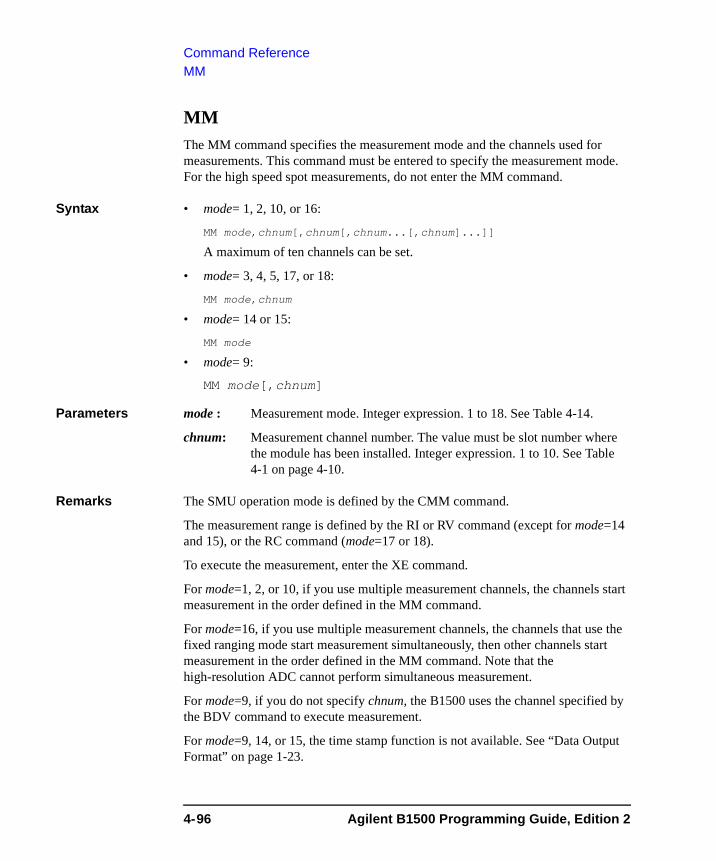
Command ReferenceMM
MM The MM command specifies the measurement mode and the channels used for measurements. This command must be entered to specify the measurement mode. For the high speed spot measurements, do not enter the MM command.
Syntax • mode= 1, 2, 10, or 16:
MM mode,chnum[,chnum[,chnum...[,chnum]...]]
A maximum of ten channels can be set.
• mode= 3, 4, 5, 17, or 18:
MM mode,chnum
• mode= 14 or 15:
MM mode
• mode= 9:
MM mode[,chnum]
Parameters mode : Measurement mode. Integer expression. 1 to 18. See Table 4-14.
chnum: Measurement channel number. The value must be slot number where the module has been installed. Integer expression. 1 to 10. See Table 4-1 on page 4-10.
Remarks The SMU operation mode is defined by the CMM command.
The measurement range is defined by the RI or RV command (except for mode=14 and 15), or the RC command (mode=17 or 18).
To execute the measurement, enter the XE command.
For mode=1, 2, or 10, if you use multiple measurement channels, the channels start measurement in the order defined in the MM command.
For mode=16, if you use multiple measurement channels, the channels that use the fixed ranging mode start measurement simultaneously, then other channels start measurement in the order defined in the MM command. Note that the high-resolution ADC cannot perform simultaneous measurement.
For mode=9, if you do not specify chnum, the B1500 uses the channel specified by the BDV command to execute measurement.
For mode=9, 14, or 15, the time stamp function is not available. See “Data Output Format” on page 1-23.
4-96 Agilent B1500 Programming Guide, Edition 2
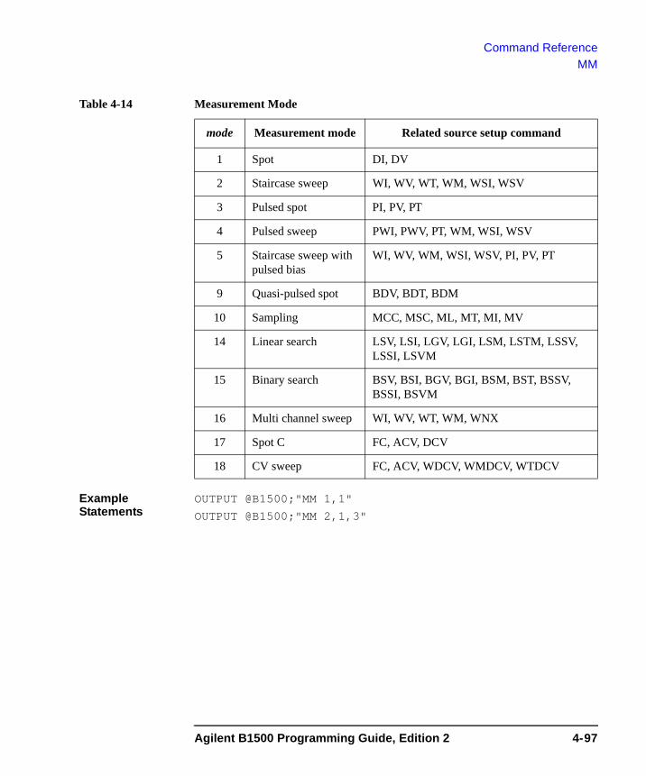
Command ReferenceMM
Table 4-14 Measurement Mode
Example Statements
OUTPUT @B1500;"MM 1,1"
OUTPUT @B1500;"MM 2,1,3"
mode Measurement mode Related source setup command
1 Spot DI, DV
2 Staircase sweep WI, WV, WT, WM, WSI, WSV
3 Pulsed spot PI, PV, PT
4 Pulsed sweep PWI, PWV, PT, WM, WSI, WSV
5 Staircase sweep with pulsed bias
WI, WV, WM, WSI, WSV, PI, PV, PT
9 Quasi-pulsed spot BDV, BDT, BDM
10 Sampling MCC, MSC, ML, MT, MI, MV
14 Linear search LSV, LSI, LGV, LGI, LSM, LSTM, LSSV, LSSI, LSVM
15 Binary search BSV, BSI, BGV, BGI, BSM, BST, BSSV, BSSI, BSVM
16 Multi channel sweep WI, WV, WT, WM, WNX
17 Spot C FC, ACV, DCV
18 CV sweep FC, ACV, WDCV, WMDCV, WTDCV
Agilent B1500 Programming Guide, Edition 2 4-97

Command ReferenceMSC
MSC The MSC command enables or disables the automatic abort function for the sampling measurement (MM10). The automatic abort function stops the measurement when one of the following conditions occurs:
• Compliance on the measurement channel
• Compliance on the non-measurement channel
• Overflow on the AD converter
• Oscillation on any channel
This command also sets the post measurement condition for the sources. After the measurement is normally completed, the voltage/current sources force the value specified by the post parameter.
If the measurement is stopped by the automatic abort function, the voltage/current sources force the base value.
Syntax MSC abort[,post]
Parameters abort : Automatic abort function. Integer expression.
1: Disables the function. Initial setting.
2: Enables the function.
post : Source output value after the measurement is normally completed. Integer expression.
1: Base value.
2: Bias value. Initial setting.
If this parameter is not set, the sources force the base value.
Output Data The B1500 returns the data measured before any abort condition is detected. Dummy data 199.999E+99 will be returned for the data after abort.
Example Statements
OUTPUT @B1500;"MSC 2"
OUTPUT @B1500;"MSC 2,2"
4-98 Agilent B1500 Programming Guide, Edition 2
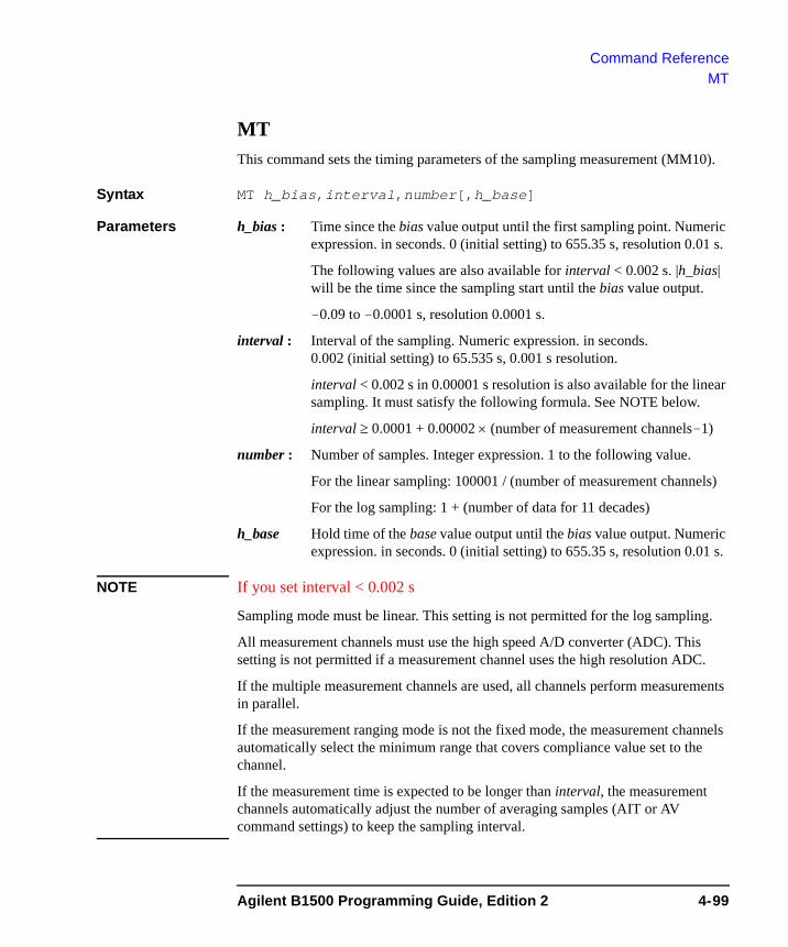
Command ReferenceMT
MT This command sets the timing parameters of the sampling measurement (MM10).
Syntax MT h_bias,interval,number[,h_base]
Parameters h_bias : Time since the bias value output until the first sampling point. Numeric expression. in seconds. 0 (initial setting) to 655.35 s, resolution 0.01 s.
The following values are also available for interval < 0.002 s. |h_bias| will be the time since the sampling start until the bias value output.
-0.09 to -0.0001 s, resolution 0.0001 s.
interval : Interval of the sampling. Numeric expression. in seconds. 0.002 (initial setting) to 65.535 s, 0.001 s resolution.
interval < 0.002 s in 0.00001 s resolution is also available for the linear sampling. It must satisfy the following formula. See NOTE below.
interval ≥ 0.0001 + 0.00002 × (number of measurement channels-1)
number : Number of samples. Integer expression. 1 to the following value.
For the linear sampling: 100001 / (number of measurement channels)
For the log sampling: 1 + (number of data for 11 decades)
h_base Hold time of the base value output until the bias value output. Numeric expression. in seconds. 0 (initial setting) to 655.35 s, resolution 0.01 s.
NOTE If you set interval < 0.002 s
Sampling mode must be linear. This setting is not permitted for the log sampling.
All measurement channels must use the high speed A/D converter (ADC). This setting is not permitted if a measurement channel uses the high resolution ADC.
If the multiple measurement channels are used, all channels perform measurements in parallel.
If the measurement ranging mode is not the fixed mode, the measurement channels automatically select the minimum range that covers compliance value set to the channel.
If the measurement time is expected to be longer than interval, the measurement channels automatically adjust the number of averaging samples (AIT or AV command settings) to keep the sampling interval.
Agilent B1500 Programming Guide, Edition 2 4-99
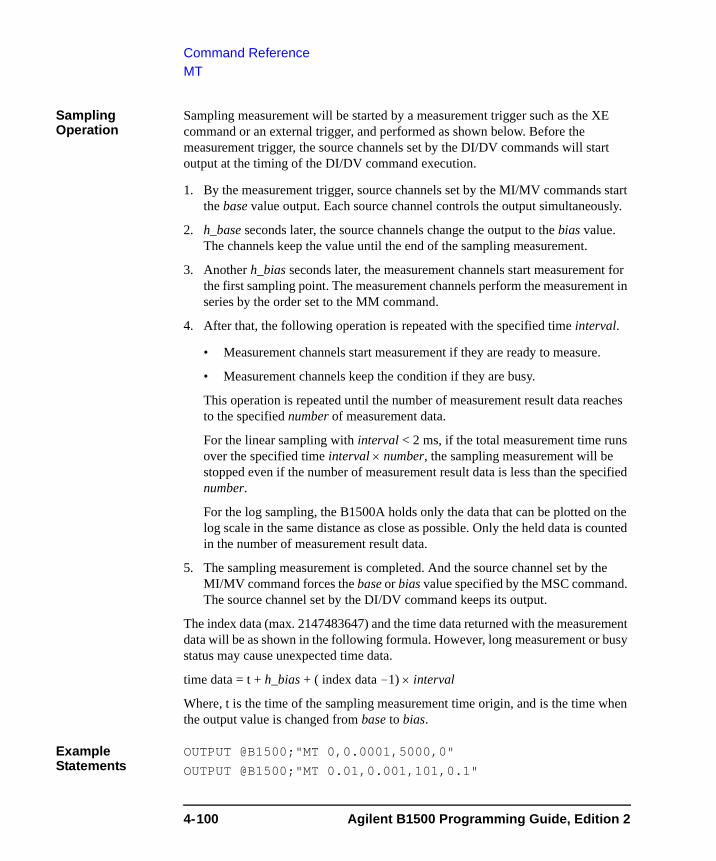
Command ReferenceMT
Sampling Operation
Sampling measurement will be started by a measurement trigger such as the XE command or an external trigger, and performed as shown below. Before the measurement trigger, the source channels set by the DI/DV commands will start output at the timing of the DI/DV command execution.
1. By the measurement trigger, source channels set by the MI/MV commands start the base value output. Each source channel controls the output simultaneously.
2. h_base seconds later, the source channels change the output to the bias value. The channels keep the value until the end of the sampling measurement.
3. Another h_bias seconds later, the measurement channels start measurement for the first sampling point. The measurement channels perform the measurement in series by the order set to the MM command.
4. After that, the following operation is repeated with the specified time interval.
• Measurement channels start measurement if they are ready to measure.
• Measurement channels keep the condition if they are busy.
This operation is repeated until the number of measurement result data reaches to the specified number of measurement data.
For the linear sampling with interval < 2 ms, if the total measurement time runs over the specified time interval × number, the sampling measurement will be stopped even if the number of measurement result data is less than the specified number.
For the log sampling, the B1500A holds only the data that can be plotted on the log scale in the same distance as close as possible. Only the held data is counted in the number of measurement result data.
5. The sampling measurement is completed. And the source channel set by the MI/MV command forces the base or bias value specified by the MSC command. The source channel set by the DI/DV command keeps its output.
The index data (max. 2147483647) and the time data returned with the measurement data will be as shown in the following formula. However, long measurement or busy status may cause unexpected time data.
time data = t + h_bias + ( index data -1) × interval
Where, t is the time of the sampling measurement time origin, and is the time when the output value is changed from base to bias.
Example Statements
OUTPUT @B1500;"MT 0,0.0001,5000,0"
OUTPUT @B1500;"MT 0.01,0.001,101,0.1"
4-100 Agilent B1500 Programming Guide, Edition 2

Command ReferenceMV
MV The MV command sets the DC voltage source (SMU) for the sampling measurement (MM10). This command setting clears, and is cleared by, the MI command setting.
The specified channel starts the base voltage output by the measurement trigger (XE command and so on), and changes the output value to bias after the hold time elapses. The hold time is set by the h_base parameter of the MT command.
When multiple channels are used, channel outputs start in the channel number order.
If the DV command is executed for this channel, the channel works as the DC voltage source set by the DV command.
Execution Conditions
If the output voltage is greater than ±42 V, the interlock circuit must be shorted.
Syntax MV chnum,vrange,base,bias[,Icomp]
Parameters chnum : Source channel number. The value must be slot number where the SMU has been installed. Integer expression. 1 to 10. See Table 4-1 on page 4-10.
vrange : Ranging type. Integer expression. The output range will be set to the minimum range that covers both base and bias values. For the limited auto ranging, the instrument never uses the range less than the specified range. See Table 4-4 on page 4-13.
base, bias : Base voltage and bias voltage (in V). Numeric expression. See Table 4-6 on page 4-14.
0 to ±100 for MPSMU/HRSMU, or 0 to ±200 for HPSMU
Icomp : Current compliance value (in A). Numeric expression. See Table 4-6 on page 4-14. If you do not set Icomp, the previous value is used. 0 A is not allowed for Icomp.
Example Statements
OUTPUT @B1500;"MV 1,12,0,5,1E-3"
See Also “MT”, “MCC”, “MSC”
Agilent B1500 Programming Guide, Edition 2 4-101
Command ReferenceNUB?
NUB? The NUB? query command checks the number of measurement data in the output data buffer, and stores the results in the output data buffer (query buffer).
Syntax NUB?
Query Response Number of measurement data<CR/LF^EOI>
Example Statements
OUTPUT @B1500;"NUB?" ENTER @B1500;A
*OPC?The *OPC? command monitors the pending operations, and places ASCII character 1 into the output queue when all pending operations are completed. Also this command sets/clears the operation complete (OPC) bit in the standard event status register as follows:
• If there are no pending operations, sets the OPC bit to 1.
• If there are any pending operations, sets the OPC bit to 0. The bit will be set to 1 when all pending operations are completed.
Syntax *OPC?
Query Response 1<CR/LF^EOI>
No response will be returned until all pending operations are completed.
Example Statements
OUTPUT @B1500;"*OPC?" ENTER @B1500;A
4-102 Agilent B1500 Programming Guide, Edition 2
Command ReferenceOS
OS The OS command causes the B1500 to send a edge trigger from the Ext Trig Out terminal. To set the trigger logic (initial setting: negative), send the TGP command for the Ext Trig Out terminal.
Syntax OS
Example Statements
OUTPUT @B1500;"OS"
OSXThe OSX command causes the B1500 to send a trigger from a trigger output terminal specified by the port parameter. To set the trigger logic (initial setting: negative), send the TGP command for the specified port.
Syntax OSX port[,level]
Parameters port : External trigger output port number. Integer expression. -2, or 1 to 16.
-2: Ext Trig Out terminal.
1 to 16: Port 1 to 16 of the digital I/O terminal.
To use a digital I/O port, send the TGP command. The port value must be same as the port value set to the TGP command.
level : Trigger output level. Integer expression. 0, 1, or 2.
0: Logical low.
1: Logical high.
2: Edge trigger (default setting).
If level is not specified, the B1500 sends the edge trigger. For the gate trigger output, send OSX port,1 when starting trigger output, and send OSX port,0 when stopping trigger output.
Example Statements
OUTPUT @B1500;"OSX 1,1"OUTPUT @B1500;"TI";1ENTER @B1500 USING "#,3X,12D,X";IdataOUTPUT @B1500;"OSX 1,0"
See Also “TGP” and “TGPC”
Agilent B1500 Programming Guide, Edition 2 4-103

Command ReferencePA
PA The PA command pauses the command execution or internal memory program execution, until the specified wait time elapses or until an event specified by the TM command is received. The event set by the TM command only releases the paused status. It does not start the measurement.
Syntax PA [wait time]
Parameters wait time : -99.9999 to 99.9999 seconds, with 100 μsec resolution. Numeric expression. If wait time is not specified or negative wait time is set, the paused status is kept until receiving an event specified by the TM command.
Remarks The TM3 command enables an external trigger from the Ext Trig In terminal as an event used to break the pause state set by the PA command.
The B1500 counts the wait time independent of the source wait time and the measurement wait time set by the WAT command. So the wait time can cover them as shown in the following program example:
OUTPUT @B1500;"CN";1OUTPUT @B1500;"WAT";1,0,1E-3 !Source Wait Time =1msOUTPUT @B1500;"WAT";2,0,1E-3 !Meas Wait Time =1msOUTPUT @B1500;"DV";1,0,5,1E-2OUTPUT @B1500;"PA";1E-3 !Wait Time =1msOUTPUT @B1500;"TI";1ENTER @B1500 USING "#,3X,12D,X";Idata
Example Statements
OUTPUT @B1500;"PA 10"
See Also “TM”
4-104 Agilent B1500 Programming Guide, Edition 2
Command ReferencePAD
PADEnables or disables parallel measurements by the multiple channels (SMU). This command is effective for the measurement channels that use the high speed A/D converter (ADC) and for the spot measurement (MM1), staircase sweep measurement (MM2), or sampling measurement (MM10).
The parallel measurements are performed at first by using the measurement channels that use the high speed ADC. And the other measurement channels perform measurements in series as defined in the MM command by using the high resolution ADC.
Syntax PAD mode
Parameters mode : 1 (enable) or 0 (disable, initial setting). Integer expression.
Example Statements
OUTPUT @B1500;"PAD 1"
Agilent B1500 Programming Guide, Edition 2 4-105
Command ReferencePAX
PAXThe PAX command pauses the command execution or internal memory program execution, until the specified wait time elapses or until an event specified by the TM command is received. The event set by the TM command only releases the paused status. It does not start the measurement.
Execution Conditions
The port parameter is meaningful only for the event (trigger input) set by the TM3 command. Set 1 (dummy) for the event set by the TM1, TM2, or TM4 command.
Syntax PAX port[,wait time]
Parameters port : External trigger input port number. Integer expression. -1, or 1 to 16.
-1: Ext Trig In terminal.
1 to 16: Port 1 to 16 of the digital I/O terminal.
To use a digital I/O port, send the TGP command. The port value must be same as the port value set to the TGP command.
wait time : -99.9999 to 99.9999 seconds, with 100 μsec resolution. Numeric expression.
If wait time is not specified or negative wait time is set, the paused status is kept until receiving an event specified by the TM command.
Remarks The TM3 command enables an external trigger from a trigger input terminal specified by the port parameter as an event used to break the pause state set by the PA command.
The B1500 counts the wait time independent of the source wait time and the measurement wait time set by the WAT command. So the wait time can cover them as shown in the following program example:
OUTPUT @B1500;"CN";1OUTPUT @B1500;"WAT";1,0,1E-3 !Source Wait Time =1msOUTPUT @B1500;"WAT";2,0,1E-3 !Meas Wait Time =1msOUTPUT @B1500;"DV";1,0,5,1E-2OUTPUT @B1500;"PAX";-1,1E-3 !Wait Time =1msOUTPUT @B1500;"TI";1ENTER @B1500 USING "#,3X,12D,X";Idata
Example Statements
OUTPUT @B1500;"PAX 1,10"
See Also “TM”, “TGP”, and “TGPC”
4-106 Agilent B1500 Programming Guide, Edition 2

Command ReferencePI
PI The PI command specifies the pulse current source and its parameters. This command also clears, and is cleared by, the PV command setting.
In the staircase sweep with pulsed bias measurement mode (set by the MM 5 command), the output forced by the PI command synchronized with the staircase sweep outputs forced by the WI or WV command.
Measurement channel performs measurement so that the pulse width and pulse period are kept. The integration time is automatically set by the instrument, and you cannot change. Note that the high-resolution ADC cannot be used for the pulsed measurements. The AAD/AIT/AV/WT command settings are ignored.
If Vcomp value is greater than ±42 V, the interlock circuit must be shorted.
Syntax PI chnum,irange,base,pulse[,Vcomp]
Parameters chnum : Pulsed source channel number. The value must be slot number where the SMU has been installed. Integer expression. 1 to 10. See Table 4-1 on page 4-10.
irange: Ranging type for pulse current output. Integer expression. The output range will be set to the minimum range that covers both base and pulse values. For the limited auto ranging, the instrument never uses the range less than the specified range. See Table 4-5 on page 4-13.
base, pulse : Pulse base current or peak current (in A). Numeric expression. See
Table 4-7 on page 4-15. base and pulse must have the same polarity.
0 to ±0.1 for MPSMU/HRSMU, or 0 to ±1 for HPSMU
Vcomp: Voltage compliance value (in V). Numeric expression. See Table 4-7 on page 4-15. If Vcomp is not specified, the previous value is set.
Compliance polarity is automatically set to the same polarity as the output value, regardless of the specified Vcomp. If the output value is 0, the polarity is set to positive.
Example Statements
OUTPUT @B1500;"PT 1,0.01"OUTPUT @B1500;"PI 1,16,0,5E-5,5"
OUTPUT @B1500;"PT 1,0.01"OUTPUT @B1500;"PI 3,0,0,5E-6"
Agilent B1500 Programming Guide, Edition 2 4-107
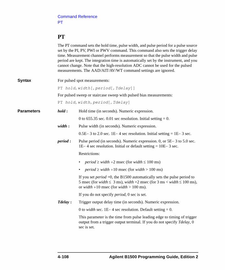
Command ReferencePT
PT The PT command sets the hold time, pulse width, and pulse period for a pulse source set by the PI, PV, PWI or PWV command. This command also sets the trigger delay time. Measurement channel performs measurement so that the pulse width and pulse period are kept. The integration time is automatically set by the instrument, and you cannot change. Note that the high-resolution ADC cannot be used for the pulsed measurements. The AAD/AIT/AV/WT command settings are ignored.
Syntax For pulsed spot measurements:
PT hold,width[,period[,Tdelay]]
For pulsed sweep or staircase sweep with pulsed bias measurements:
PT hold,width,period[,Tdelay]
Parameters hold : Hold time (in seconds). Numeric expression.
0 to 655.35 sec. 0.01 sec resolution. Initial setting = 0.
width : Pulse width (in seconds). Numeric expression.
0.5E− 3 to 2.0 sec. 1E− 4 sec resolution. Initial setting = 1E− 3 sec.
period : Pulse period (in seconds). Numeric expression. 0, or 5E− 3 to 5.0 sec. 1E− 4 sec resolution. Initial or default setting = 10E− 3 sec.
Restrictions:
• period ≥ width +2 msec (for width ≤ 100 ms)
• period ≥ width +10 msec (for width > 100 ms)
If you set period =0, the B1500 automatically sets the pulse period to 5 msec (for width ≤ 3 ms), width +2 msec (for 3 ms < width ≤ 100 ms), or width +10 msec (for width > 100 ms).
If you do not specify period, 0 sec is set.
Tdelay : Trigger output delay time (in seconds). Numeric expression.
0 to width sec. 1E− 4 sec resolution. Default setting = 0.
This parameter is the time from pulse leading edge to timing of trigger output from a trigger output terminal. If you do not specify Tdelay, 0 sec is set.
4-108 Agilent B1500 Programming Guide, Edition 2
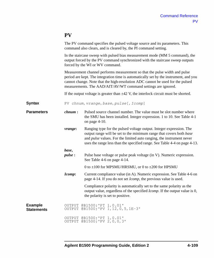
Command ReferencePV
PV The PV command specifies the pulsed voltage source and its parameters. This command also clears, and is cleared by, the PI command setting.
In the staircase sweep with pulsed bias measurement mode (MM 5 command), the output forced by the PV command synchronized with the staircase sweep outputs forced by the WI or WV command.
Measurement channel performs measurement so that the pulse width and pulse period are kept. The integration time is automatically set by the instrument, and you cannot change. Note that the high-resolution ADC cannot be used for the pulsed measurements. The AAD/AIT/AV/WT command settings are ignored.
If the output voltage is greater than ±42 V, the interlock circuit must be shorted.
Syntax PV chnum,vrange,base,pulse[,Icomp]
Parameters chnum : Pulsed source channel number. The value must be slot number where the SMU has been installed. Integer expression. 1 to 10. See Table 4-1 on page 4-10.
vrange: Ranging type for the pulsed voltage output. Integer expression. The output range will be set to the minimum range that covers both base and pulse values. For the limited auto ranging, the instrument never uses the range less than the specified range. See Table 4-4 on page 4-13.
base, pulse : Pulse base voltage or pulse peak voltage (in V). Numeric expression.
See Table 4-6 on page 4-14.
0 to ±100 for MPSMU/HRSMU, or 0 to ±200 for HPSMU
Icomp: Current compliance value (in A). Numeric expression. See Table 4-6 on page 4-14. If you do not set Icomp, the previous value is used.
Compliance polarity is automatically set to the same polarity as the output value, regardless of the specified Icomp. If the output value is 0, the polarity is set to positive.
Example Statements
OUTPUT @B1500;"PT 1,0.01"OUTPUT @B1500;"PV 1,12,0,5,1E-3"
OUTPUT @B1500;"PT 1,0.01"OUTPUT @B1500;"PV 2,0,0,3"
Agilent B1500 Programming Guide, Edition 2 4-109
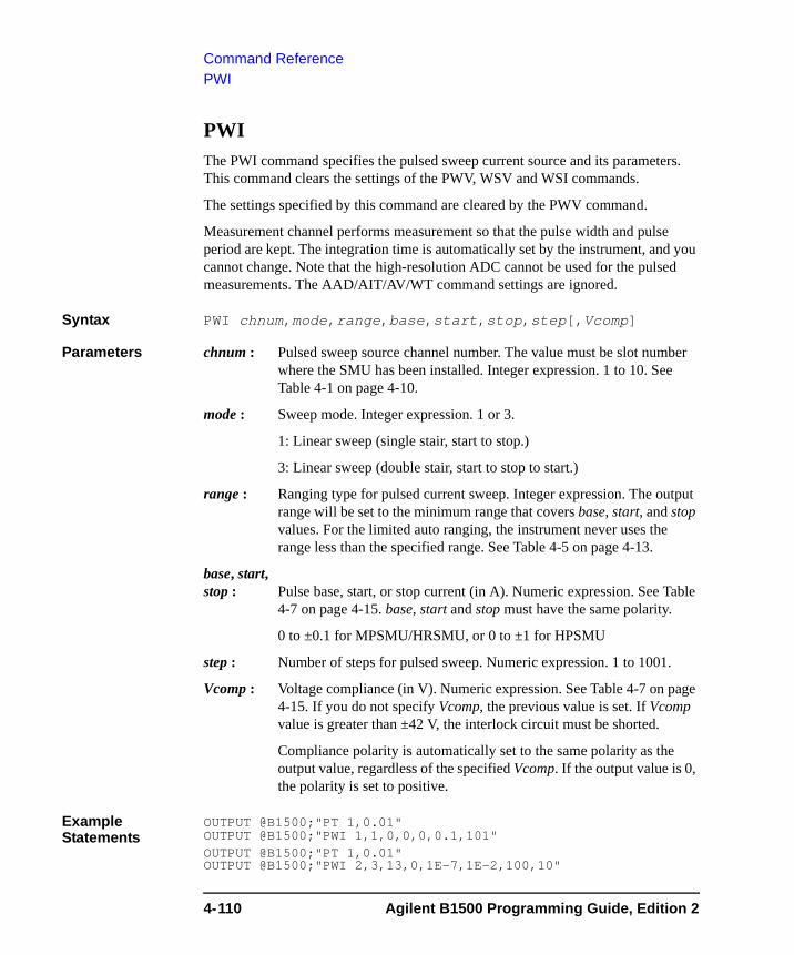
Command ReferencePWI
PWI The PWI command specifies the pulsed sweep current source and its parameters. This command clears the settings of the PWV, WSV and WSI commands.
The settings specified by this command are cleared by the PWV command.
Measurement channel performs measurement so that the pulse width and pulse period are kept. The integration time is automatically set by the instrument, and you cannot change. Note that the high-resolution ADC cannot be used for the pulsed measurements. The AAD/AIT/AV/WT command settings are ignored.
Syntax PWI chnum,mode,range,base,start,stop,step[,Vcomp]
Parameters chnum : Pulsed sweep source channel number. The value must be slot number where the SMU has been installed. Integer expression. 1 to 10. See Table 4-1 on page 4-10.
mode : Sweep mode. Integer expression. 1 or 3.
1: Linear sweep (single stair, start to stop.)
3: Linear sweep (double stair, start to stop to start.)
range : Ranging type for pulsed current sweep. Integer expression. The output range will be set to the minimum range that covers base, start, and stop values. For the limited auto ranging, the instrument never uses the range less than the specified range. See Table 4-5 on page 4-13.
base, start, stop : Pulse base, start, or stop current (in A). Numeric expression. See Table
4-7 on page 4-15. base, start and stop must have the same polarity.
0 to ±0.1 for MPSMU/HRSMU, or 0 to ±1 for HPSMU
step : Number of steps for pulsed sweep. Numeric expression. 1 to 1001.
Vcomp : Voltage compliance (in V). Numeric expression. See Table 4-7 on page 4-15. If you do not specify Vcomp, the previous value is set. If Vcomp value is greater than ±42 V, the interlock circuit must be shorted.
Compliance polarity is automatically set to the same polarity as the output value, regardless of the specified Vcomp. If the output value is 0, the polarity is set to positive.
Example Statements
OUTPUT @B1500;"PT 1,0.01"OUTPUT @B1500;"PWI 1,1,0,0,0,0.1,101"OUTPUT @B1500;"PT 1,0.01"OUTPUT @B1500;"PWI 2,3,13,0,1E-7,1E-2,100,10"
4-110 Agilent B1500 Programming Guide, Edition 2
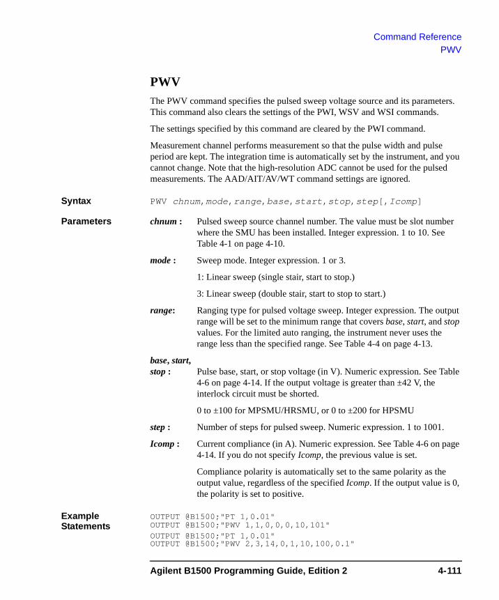
Command ReferencePWV
PWV The PWV command specifies the pulsed sweep voltage source and its parameters. This command also clears the settings of the PWI, WSV and WSI commands.
The settings specified by this command are cleared by the PWI command.
Measurement channel performs measurement so that the pulse width and pulse period are kept. The integration time is automatically set by the instrument, and you cannot change. Note that the high-resolution ADC cannot be used for the pulsed measurements. The AAD/AIT/AV/WT command settings are ignored.
Syntax PWV chnum,mode,range,base,start,stop,step[,Icomp]
Parameters chnum : Pulsed sweep source channel number. The value must be slot number where the SMU has been installed. Integer expression. 1 to 10. See Table 4-1 on page 4-10.
mode : Sweep mode. Integer expression. 1 or 3.
1: Linear sweep (single stair, start to stop.)
3: Linear sweep (double stair, start to stop to start.)
range: Ranging type for pulsed voltage sweep. Integer expression. The output range will be set to the minimum range that covers base, start, and stop values. For the limited auto ranging, the instrument never uses the range less than the specified range. See Table 4-4 on page 4-13.
base, start, stop : Pulse base, start, or stop voltage (in V). Numeric expression. See Table
4-6 on page 4-14. If the output voltage is greater than ±42 V, the interlock circuit must be shorted.
0 to ±100 for MPSMU/HRSMU, or 0 to ±200 for HPSMU
step : Number of steps for pulsed sweep. Numeric expression. 1 to 1001.
Icomp : Current compliance (in A). Numeric expression. See Table 4-6 on page 4-14. If you do not specify Icomp, the previous value is set.
Compliance polarity is automatically set to the same polarity as the output value, regardless of the specified Icomp. If the output value is 0, the polarity is set to positive.
Example Statements
OUTPUT @B1500;"PT 1,0.01"OUTPUT @B1500;"PWV 1,1,0,0,0,10,101"OUTPUT @B1500;"PT 1,0.01"OUTPUT @B1500;"PWV 2,3,14,0,1,10,100,0.1"
Agilent B1500 Programming Guide, Edition 2 4-111
Command ReferenceRC
RCThe RC command specifies the measurement range or the measurement ranging type of the MFCMU. In the initial setting, the auto ranging is set. The range changing occurs immediately after the trigger (that is, during the measurements).
For the high speed spot measurement, use the TC/TTC command.
The range setting is cleared by the CL, CA, IN, *TST?, *RST or a device clear (HP BASIC CLEAR) command.
Syntax RC chnum,mode[,range]
Parameters chnum : Measurement channel number. The value must be slot number where the MFCMU has been installed. Integer expression. 1 to 10. See Table 4-1 on page 4-10.
mode : Ranging mode. 0 (auto ranging. initial setting) or 2 (fixed range).
range : Measurement range. Needs to set when mode=2. Integer (0 or more). 50 Ω, 100 Ω, 300 Ω, 1 kΩ, 3 kΩ, 10 kΩ, 30 kΩ, 100 kΩ, and 300 kΩ are selectable. See Table 4-9 on page 4-17. Available measurement ranges depend on the output signal frequency set by the FC command.
Example Statements
OUTPUT @B1500;"RC 8,0"
OUTPUT @B1500;"RC 8,2,10000"
4-112 Agilent B1500 Programming Guide, Edition 2
Command ReferenceRCV
RCV The RCV command enables the modules that fail the self-test or self-calibration so that it can receive commands again.
After the RCV command, enter the *OPC? command to confirm that the command execution is completed.
This command should only be used for servicing the B1500.
Syntax RCV [module]
Parameters module : Failed module to enable. Integer expression. 0 to 11.
0: All failed modules. Default setting.
1 to 10: Module installed in the slot specified by module.
11: Mainframe.
If module specifies the slot that installs no module, this command causes an error.
Example Statements
OUTPUT @B1500;"RCV 1"OUTPUT @B1500;"*OPC?"ENTER @B1500;A
Agilent B1500 Programming Guide, Edition 2 4-113
Command ReferenceRI
RI The RI command specifies the current measurement range or ranging type. In the initial setting, the auto ranging is set. The range changing occurs immediately after the trigger (that is, during the measurements). Current measurement channel can be decided by the CMM command setting and the channel output mode (voltage or current).
For the high speed spot measurement, use the TI/TTI command.
The range setting is cleared by the CL, CA, IN, *TST?, *RST or a device clear (HP BASIC CLEAR) command.
Syntax RI chnum,range
Parameters chnum : Current measurement channel number. The value must be slot number where the SMU has been installed. Integer expression. 1 to 10. See Table 4-1 on page 4-10.
range : Measurement range or ranging type. Integer expression. See Table 4-3 on page 4-12.
If you select the fixed range, the instrument performs measurement by using the specified range.
For the auto or limited auto ranging, the measurement range will be set to the minimum range that covers the measured values. However, the instrument never uses the range less than the specified range for the limited auto ranging.
For the measurement mode that uses pulse source, if you select the auto or limited auto ranging, the measurement channel uses the minimum range that covers the compliance value or current output range.
Example Statements
OUTPUT @B1500;"RI 1,0"
OUTPUT @B1500;"RI 2,-20"
4-114 Agilent B1500 Programming Guide, Edition 2

Command ReferenceRM
RMThis command specifies the auto range operation for the current measurement.
Syntax RM chnum,mode[,rate]
where the rate parameter is available for mode=2 or 3.
Parameters chnum : Current measurement channel number. The value must be slot number where the SMU has been installed. Integer expression. 1 to 10. See Table 4-1 on page 4-10.
mode : Range changing operation mode. Integer expression. 1, 2 or 3.
where current1 and current2 are given by the following formula:
current1 = measurement range × rate /100current2 = measurement range × rate /1000
For example, if measurement range=10 mA and rate=90, these values are as follows:
current1 = 9 mAcurrent2 = 0.9 mA
rate: Parameter used to calculate the current value. Numeric expression. 11 to 100. Default setting is 50.
Example Statements
OUTPUT @B1500;"RM 1,2"
OUTPUT @B1500;"RM 2,3,60"
mode Description
1 Initial setting. If you set mode=1, do not set rate.
2 If measured data ≥ current1, the range changes up after measurement.
3 If measured data ≤ current2, the range changes down immediately, and if measured data ≥ current1, the range changes up after measurement.
Agilent B1500 Programming Guide, Edition 2 4-115
Command Reference*RST
*RST The *RST command resets the B1500 to the initial settings. This command does not clear the program memory and the self-calibration data.
Syntax *RST
Remarks If you want to reset channels while a sweep measurement is being performed, you must first send the AB command, then the *RST command.
Example Statement
OUTPUT @B1500;"*RST"
RU The RU command sequentially executes the internal memory programs.
Execution Conditions
The specified programs have been stored by using the ST and END commands, from the start program number through the stop program number.
Syntax RU start,stop
Parameters start : Start program number. Numeric expression. 1 to 2000.
stop : Stop program number. Numeric expression. 1 to 2000.
where stop value must be greater than or equal to the start value.
Example Statements
OUTPUT @B1500;"RU 1,10"
OUTPUT @B1500;"RU 3,6"
4-116 Agilent B1500 Programming Guide, Edition 2
Command ReferenceRV
RVThe RV command specifies the voltage measurement range or ranging type. In the initial setting, the auto ranging is set. The range changing occurs immediately after the trigger (that is, during the measurements). Voltage measurement channel can be decided by the CMM command setting and the channel output mode (voltage or current).
For the high speed spot measurement, use the TV/TTV command.
The range setting is cleared by the CL, CA, IN, *TST?, *RST or a device clear (HP BASIC CLEAR) command.
Syntax RV chnum,range
Parameters chnum : Voltage measurement channel number. The value must be slot number where the SMU has been installed. Integer expression. 1 to 10. See Table 4-1 on page 4-10.
range : Measurement range or ranging type. Integer expression. See Table 4-2 on page 4-11.
If you select the fixed range, the instrument performs measurement by using the specified range.
For the auto or limited auto ranging, the measurement range will be set to the minimum range that covers the measured values. However, the instrument never uses the range less than the specified range for the limited auto ranging.
For the measurement mode that uses pulse source, if you select the auto or limited auto ranging, the measurement channel uses the minimum range that covers the compliance value or voltage output range.
Example Statements
OUTPUT @B1500;"RV 2,-15"
OUTPUT @B1500;"RV 1,12"
Agilent B1500 Programming Guide, Edition 2 4-117
Command ReferenceRZ
RZ The RZ command returns the channel to the settings that are stored by the DZ command and clears the stored settings.
The DZ command stores the channel settings (V/I output values, V/I output ranges, V/I compliance values, and so on), then sets the channel to 0 V.
Execution Conditions
The DZ command has been executed for the specified channel. And the CL, CA, *TST?, *RST or a device clear (HP BASIC CLEAR) command has not been executed for the specified channel.
Syntax RZ [chnum[,chnum...[,chnum]...]]
A maximum of ten channels can be set.
Parameters chnum : Channel number. The value must be slot number where the module has been installed. Integer expression. 1 to 10. See Table 4-1 on page 4-10.
If you do not specify this parameter, this command returns the settings for all channels that satisfy the conditions described in “Execution Conditions” above, in the order that the DZ command stored them.
You can specify up to ten channels at once using the RZ command. The B1500 returns the stored settings in the order specified.
Example Statements
OUTPUT @B1500;"RZ"
OUTPUT @B1500;"RZ 1,2,3"
4-118 Agilent B1500 Programming Guide, Edition 2
Command ReferenceSAL
SALThis function is available for the Agilent B1500 installed with the high resolution SMU (HRSMU) and the atto sense and switch unit (ASU).
Disables or enables the connection status indicator (LED) of the ASU. This command is effective for the specified channel.
Syntax SAL chnum,mode
Parameters chnum : Slot number where the HRSMU has been installed. The ASU must be connected to the HRSMU. Integer expression. 1 to 10.
mode : 0: Disables the indicator.
1: Enables the indicator. Default setting.
Example Statements
OUTPUT @B1500;"SAL 1,0"
NOTE To use ASU
Before turn the Agilent B1500 on, connect the ASU to the HRSMU properly. The ASU will add the 1 pA range to the HRSMU. If you use other instrument such as the capacitance meter, connect the instrument to the AUX input of the ASU. The ASU provides the input selection function.
Remember that the series resistor in the HRSMU connected to the ASU cannot be used.
Agilent B1500 Programming Guide, Edition 2 4-119
Command ReferenceSAP
SAPThis function is available for the Agilent B1500 installed with the high resolution SMU (HRSMU) and the atto sense and switch unit (ASU). This command is not effective when the High Voltage indicator of the Agilent B1500 has been lighted.
Controls the connection path of the ASU. Switches the ASU input resource (HRSMU or the instrument connected to the AUX input) to be connected to the ASU output. This command is effective for the specified channel.
After the Agilent B1500 is turned on or the CL command is entered, the ASU output will be connected to the SMU connector side, but the HRSMU will not be enabled yet. After this command is entered with path=1, the HRSMU specified by chnum cannot be used. After this command is entered with path=0 or the CN command is entered, the HRSMU output will appear on the ASU output.Then the HRSMU output will be 0 V.
Syntax SAP chnum,path
Parameters chnum : Slot number where the HRSMU has been installed. The ASU must be connected to the HRSMU. Integer expression. 1 to 10.
path : Path connected to the ASU output. 0 or 1.
0: The ASU output will be connected to the SMU connector side.
1: The ASU output will be connected to the AUX connector side.
Example Statements
OUTPUT @B1500;"SAP 1,1"
4-120 Agilent B1500 Programming Guide, Edition 2
Command ReferenceSAR
SARThis function is available for the Agilent B1500 installed with the high resolution SMU (HRSMU) and the atto sense and switch unit (ASU).
Enables or disables the 1 pA range for the auto ranging operation. This command is effective for the specified channel.
Syntax SAR chnum,mode
Parameters chnum : Slot number where the HRSMU has been installed. The ASU must be connected to the HRSMU. Integer expression. 1 to 10.
mode : 0: Enables 1 pA range for the auto ranging operation.
1: Disables 1 pA range for the auto ranging operation. Initial setting
Example Statements
OUTPUT @B1500;"SAR 1,0"
NOTE To use ASU
Before turn the Agilent B1500 on, connect the ASU to the HRSMU properly. The ASU will add the 1 pA range to the HRSMU. Remember that the series resistor in the HRSMU connected to the ASU cannot be used.
SCR The SCR command scratches the specified program from the internal program memory.
Syntax SCR [pnum]
Parameters pnum : Program number. Numeric expression. 1 to 2000. If you do not specify this parameter, this command scratches all programs stored in the internal program memory.
Example Statements
OUTPUT @B1500;"SCR"
OUTPUT @B1500;"SCR 5"
Agilent B1500 Programming Guide, Edition 2 4-121
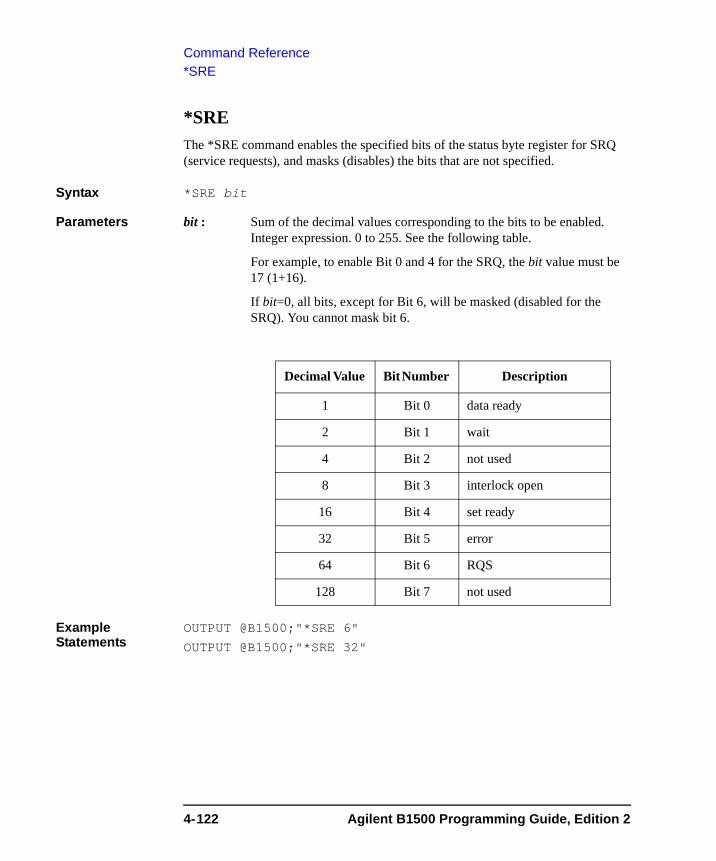
Command Reference*SRE
*SRE The *SRE command enables the specified bits of the status byte register for SRQ (service requests), and masks (disables) the bits that are not specified.
Syntax *SRE bit
Parameters bit : Sum of the decimal values corresponding to the bits to be enabled. Integer expression. 0 to 255. See the following table.
For example, to enable Bit 0 and 4 for the SRQ, the bit value must be 17 (1+16).
If bit=0, all bits, except for Bit 6, will be masked (disabled for the SRQ). You cannot mask bit 6.
Example Statements
OUTPUT @B1500;"*SRE 6"
OUTPUT @B1500;"*SRE 32"
Decimal Value Bit Number Description
1 Bit 0 data ready
2 Bit 1 wait
4 Bit 2 not used
8 Bit 3 interlock open
16 Bit 4 set ready
32 Bit 5 error
64 Bit 6 RQS
128 Bit 7 not used
4-122 Agilent B1500 Programming Guide, Edition 2
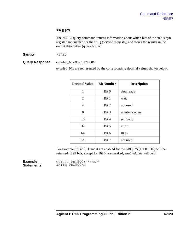
Command Reference*SRE?
*SRE? The *SRE? query command returns information about which bits of the status byte register are enabled for the SRQ (service requests), and stores the results in the output data buffer (query buffer).
Syntax *SRE?
Query Response enabled_bits<CR/LF^EOI>
enabled_bits are represented by the corresponding decimal values shown below.
For example, if Bit 0, 3, and 4 are enabled for the SRQ, 25 (1 + 8 + 16) will be returned. If all bits, except for Bit 6, are masked, enabled_bits will be 0.
Example Statements
OUTPUT @B1500;"*SRE?" ENTER @B1500;A
Decimal Value Bit Number Description
1 Bit 0 data ready
2 Bit 1 wait
4 Bit 2 not used
8 Bit 3 interlock open
16 Bit 4 set ready
32 Bit 5 error
64 Bit 6 RQS
128 Bit 7 not used
Agilent B1500 Programming Guide, Edition 2 4-123
Command ReferenceSSL
SSLThis function is available for the Agilent B1500 installed with the multi frequency capacitance measurement unit (MFCMU) and the SMU CMU unify unit (SCUU). To use the SCUU, connect it to the MFCMU and two SMUs (MPSMU or HRSMU) correctly. The SCUU cannot be used with the HPSMU or when only one SMU is connected.
Disables or enables the connection status indicator (LED) of the SCUU.
Syntax SAL chnum,mode
Parameters chnum : Slot number where the MFCMU has been installed. Integer expression. 1 to 10.
mode : 0: Disables the indicator.
1: Enables the indicator. Initial setting.
Example Statements
OUTPUT @B1500;"SSL 9,0"
NOTE To use SCUU
Before turn the Agilent B1500 on, connect the SCUU to the MFCMU and two MPSMU/HRSMUs properly. The SCUU is used to switch the module (SMU or MFCMU) connected to the DUT.
4-124 Agilent B1500 Programming Guide, Edition 2
Command ReferenceSSP
SSPThis function is available for the Agilent B1500 installed with the multi frequency capacitance measurement unit (MFCMU) and the SMU CMU unify unit (SCUU). To use the SCUU, connect it to the MFCMU and two SMUs (MPSMU or HRSMU) correctly. The SCUU cannot be used with the HPSMU or when only one SMU is connected.
Controls the connection path of the SCUU. Switches the SCUU input resource (MFCMU or SMU) to be connected to the SCUU output.
When the B1500 is turned on, the SCUU input to output connection is not made (open). When the SCUU input to output connection is made, the measurement unit output switch will be automatically set to ON.
Syntax SAP chnum,path
Parameters chnum : Slot number where the MFCMU has been installed. Integer expression. 1 to 10.
path : Path connected to the SCUU output. 1 to 4. See Table 4-15.
Example Statements
OUTPUT @B1500;"SSP 9,4"
Remarks When the connection is changed from SMU to MFCMU, the SMU output will be set as follows. The other setup parameters are not changed.
Output voltage 0 V
Output range 100 V
Compliance 20 mA
Series resistance OFF
When the connection is changed from MFCMU to SMU, the SMU output will be set as follows. The other setup parameters are not changed.
Output voltage 0 V
Output range 20 V
Compliance 100 μA
Series resistance Condition before the connection is changed from SMU to MFCMU
Agilent B1500 Programming Guide, Edition 2 4-125
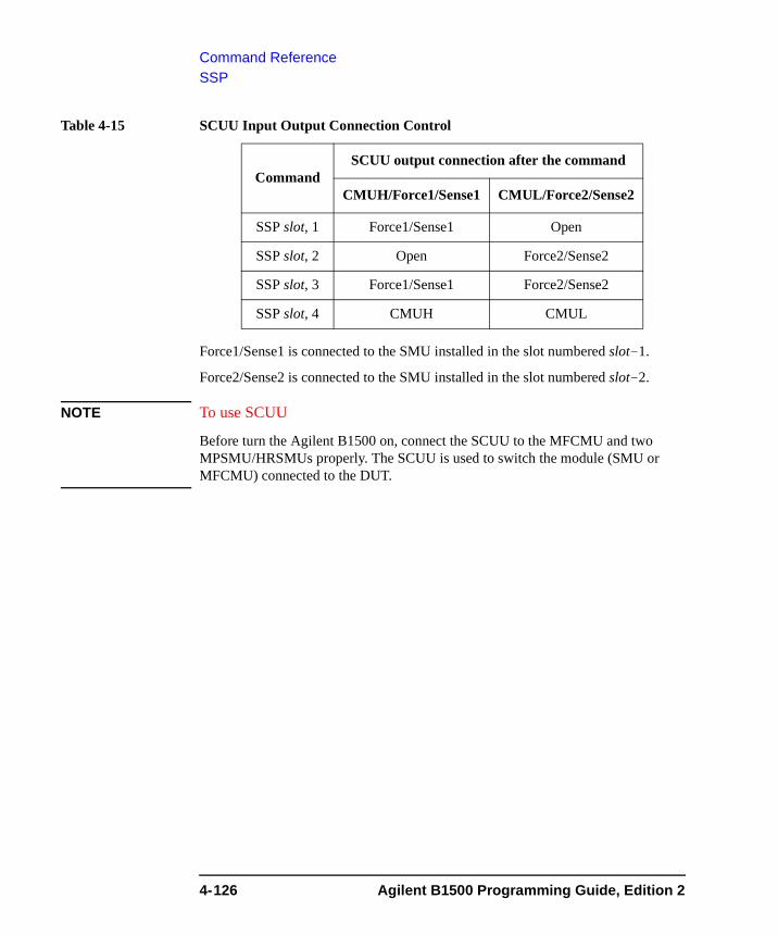
Command ReferenceSSP
Table 4-15 SCUU Input Output Connection Control
Force1/Sense1 is connected to the SMU installed in the slot numbered slot-1.
Force2/Sense2 is connected to the SMU installed in the slot numbered slot-2.
NOTE To use SCUU
Before turn the Agilent B1500 on, connect the SCUU to the MFCMU and two MPSMU/HRSMUs properly. The SCUU is used to switch the module (SMU or MFCMU) connected to the DUT.
CommandSCUU output connection after the command
CMUH/Force1/Sense1 CMUL/Force2/Sense2
SSP slot, 1 Force1/Sense1 Open
SSP slot, 2 Open Force2/Sense2
SSP slot, 3 Force1/Sense1 Force2/Sense2
SSP slot, 4 CMUH CMUL
4-126 Agilent B1500 Programming Guide, Edition 2
Command ReferenceSSR
SSRThis command sets the connection mode of a SMU series resistor (approx. 1 MΩ) for each channel.
If the output switch is opened, the SSR command just sets the mode, and the CN command connects or disconnects the series resistor.
If the output switch is already closed, the SSR command connects the series resistor to the SMU output. Then the output forces 0 V one moment.
A series resistor is mounted on each module. If you use a series resistor, the voltage you set is applied to the near side of the series resistor. Thus, the voltage will be divided by the series resistor and the device under test.
Execution Conditions
The series resistor cannot be used for the measurements that use the high resolution SMU (HRSMU) connected to the atto sense and switch unit (ASU) or the measurements that use 1 A range of the high power SMU (HPSMU).
The channel must not be in the high voltage state (forcing more than ±42 V, or voltage compliance set to more than ±42 V).
Syntax SSR chnum,mode
Parameters chnum : Channel number. The value must be slot number where the SMU has been installed. Integer expression. 1 to 10. See Table 4-1 on page 4-10.
mode : Status of the series resistor. Integer expression.
0: Disconnect (initial setting).
1: Connect.
Example Statements
OUTPUT @B1500;"SSR 1,1"
OUTPUT @B1500;"SSR 2,1"
Agilent B1500 Programming Guide, Edition 2 4-127
Command ReferenceST
ST The ST command is used with the END command to store a program in the internal program memory that can store 2,000 programs maximum, and a total of 40,000 commands.
The ST command indicates the start of the program, and assigns the program number. If the assigned program number already exists, the B1500 deletes the old program, and stores the new one.
The END command indicates the end of the program. If the END command is not included, the B1500 stores the commands until the program memory is full.
Use the DO or RU command to execute stored programs.
Syntax STpnum[;command[;command...[;command]...];END
or
ST pnum [command] [command]
: :
[command] END
Parameters pnum : Program number. Integer expression. 1 to 2000.
command : Command stored in the internal program memory. Specify commands according to normal syntax − no special syntax is necessary.
For the commands that cannot stored in the program memory, refer to Table 2-1 on page 2-32.
Example Statements
Example 1:
OUTPUT @B1500;"ST1;CN1;DV1,0,5,1E-4;TI1,0;CL1" OUTPUT @B1500;"END"
Example 2:
OUTPUT @B1500;"ST 1"OUTPUT @B1500;"CN 1"OUTPUT @B1500;"DV 1,0,5,1E-4"OUTPUT @B1500;"TI 1,0"OUTPUT @B1500;"CL 1"OUTPUT @B1500;"END"
4-128 Agilent B1500 Programming Guide, Edition 2
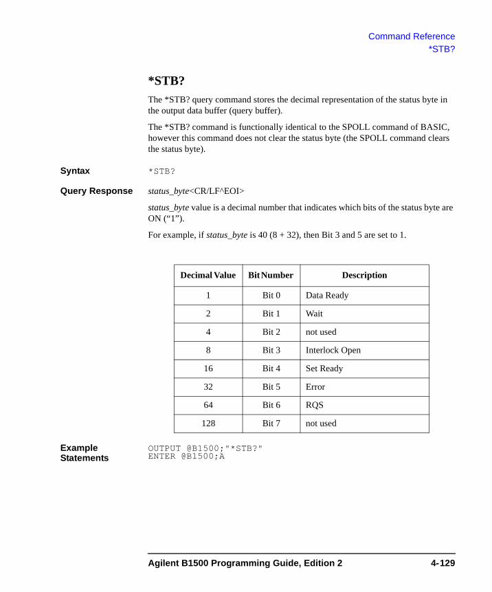
Command Reference*STB?
*STB? The *STB? query command stores the decimal representation of the status byte in the output data buffer (query buffer).
The *STB? command is functionally identical to the SPOLL command of BASIC, however this command does not clear the status byte (the SPOLL command clears the status byte).
Syntax *STB?
Query Response status_byte<CR/LF^EOI>
status_byte value is a decimal number that indicates which bits of the status byte are ON (“1”).
For example, if status_byte is 40 (8 + 32), then Bit 3 and 5 are set to 1.
Example Statements
OUTPUT @B1500;"*STB?" ENTER @B1500;A
Decimal Value Bit Number Description
1 Bit 0 Data Ready
2 Bit 1 Wait
4 Bit 2 not used
8 Bit 3 Interlock Open
16 Bit 4 Set Ready
32 Bit 5 Error
64 Bit 6 RQS
128 Bit 7 not used
Agilent B1500 Programming Guide, Edition 2 4-129
Command ReferenceTACV
TACVThis command forces AC voltage from the MFCMU, and returns the time data from timer reset to the start of output.
Execution Conditions
The CN command has been executed for the specified channel.
The FC command has been executed to set the frequency of the AC voltage.
This command is not effective for the 4 byte binary data output format (FMT3 and FMT4).
Syntax TACV chnum,voltage
Parameters chnum : Source channel number. The value must be slot number where the MFCMU has been installed. Integer expression. 1 to 10. See Table 4-1 on page 4-10.
voltage : Oscillator level of the output AC voltage (in V). Numeric expression.
0 (initial setting) to 0.25 V, 0.001 V step
Remarks To read the time data with the best resolution (100 μs), the timer must be cleared every 100 sec or less for the FMT1, 2, or 5 data output format, or every 1000 sec or less for the FMT 11, 12, 15, 21, 22, or 25 data output format.
Example Statements
OUTPUT @B1500;"TACV 7,0.01"ENTER @B1500 USING "#,5X,13D,X";Time
4-130 Agilent B1500 Programming Guide, Edition 2
Command ReferenceTC
TCThe TC command performs the high speed spot measurement by using the MFCMU, and returns the measurement data. The command starts a measurement regardless of the trigger mode (TM command) and the measurement mode (MM command).
The MFCMU measures the primary parameter and the secondary parameter (for example, Cp and G). Use the IMP command to select the measurement parameters. See “IMP” on page 4-73.
Execution Conditions
CN command has been executed for the specified channel.
IMP command has been executed.
Syntax TC chnum,mode[,range]
Parameters chnum : Measurement channel number. The value must be slot number where the MFCMU has been installed. Integer expression. 1 to 10. See Table 4-1 on page 4-10.
mode : Ranging mode. 0 (auto ranging. initial setting) or 2 (fixed range).
range : Measurement range. Needs to set when mode=2. Integer (0 or more). 50 Ω, 100 Ω, 300 Ω, 1 kΩ, 3 kΩ, 10 kΩ, 30 kΩ, 100 kΩ, and 300 kΩ are selectable. See Table 4-9 on page 4-17. Available measurement ranges depend on the output signal frequency set by the FC command.
Example Statements
OUTPUT @B1500;"TC 8,2,1000"ENTER @B1500 USING "#,3X,12D,X";CdataENTER @B1500 USING "#,3X,12D,X";Gdata
Agilent B1500 Programming Guide, Edition 2 4-131
Command ReferenceTDCV
TDCVForces DC voltage from the MFCMU or the SMU connected to the Force1/Sense1 terminals of the SCUU (SMU CMU unify unit), and returns the time data from timer reset to the start of output.
Execution Conditions
The CN command has been executed for the specified channel (MFCMU).
If you want to apply DC voltage over ±25 V, the SCUU must be connected correctly. The SCUU can be used with the MFCMU and two SMUs (MPSMU or HRSMU). The SCUU cannot be used if the HPSMU is connected to the SCUU or if the number of SMUs connected to the SCUU is only one.
This command is not effective for the 4 byte binary data output format (FMT3 and FMT4).
Syntax TDCV chnum,voltage
Parameters chnum : Source channel number. The value must be slot number where the MFCMU has been installed. Integer expression. 1 to 10. See Table 4-1 on page 4-10.
voltage : DC voltage (in V). Numeric expression.
0 (initial setting) to ±100 V
Source module is automatically selected by the setting value. The MFCMU is selected if voltage is ±25 V or less (setting resolution: 0.001 V), or the SMU is selected if voltage is greater than ±25 V (setting resolution: 0.005 V).
The SMU will operate with the 100 V limited auto ranging and 20 mA compliance settings.
If the output voltage is greater than ±42 V, the interlock circuit must be shorted.
Remarks To read the time data with the best resolution (100 μs), the timer must be cleared every 100 sec or less for the FMT1, 2, or 5 data output format, or every 1000 sec or less for the FMT 11, 12, 15, 21, 22, or 25 data output format.
Example Statements
OUTPUT @B1500;"TDCV 7,1"ENTER @B1500 USING "#,5X,13D,X";Time
4-132 Agilent B1500 Programming Guide, Edition 2
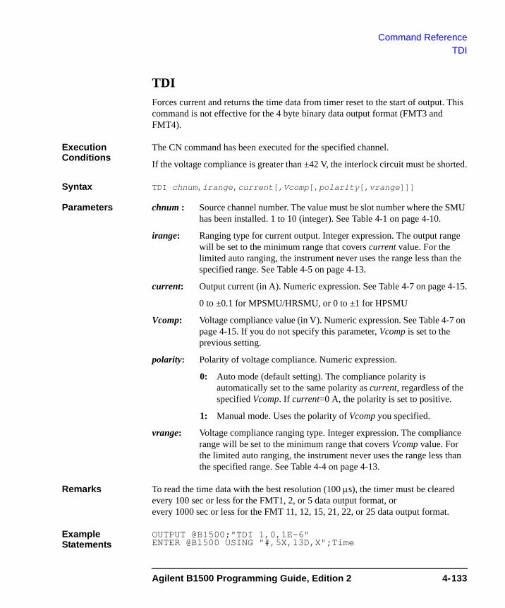
Command ReferenceTDI
TDIForces current and returns the time data from timer reset to the start of output. This command is not effective for the 4 byte binary data output format (FMT3 and FMT4).
Execution Conditions
The CN command has been executed for the specified channel.
If the voltage compliance is greater than ±42 V, the interlock circuit must be shorted.
Syntax TDI chnum,irange,current[,Vcomp[,polarity[,vrange]]]
Parameters chnum : Source channel number. The value must be slot number where the SMU has been installed. 1 to 10 (integer). See Table 4-1 on page 4-10.
irange: Ranging type for current output. Integer expression. The output range will be set to the minimum range that covers current value. For the limited auto ranging, the instrument never uses the range less than the specified range. See Table 4-5 on page 4-13.
current: Output current (in A). Numeric expression. See Table 4-7 on page 4-15.
0 to ±0.1 for MPSMU/HRSMU, or 0 to ±1 for HPSMU
Vcomp: Voltage compliance value (in V). Numeric expression. See Table 4-7 on page 4-15. If you do not specify this parameter, Vcomp is set to the previous setting.
polarity: Polarity of voltage compliance. Numeric expression.
0: Auto mode (default setting). The compliance polarity is automatically set to the same polarity as current, regardless of the specified Vcomp. If current=0 A, the polarity is set to positive.
1: Manual mode. Uses the polarity of Vcomp you specified.
vrange: Voltage compliance ranging type. Integer expression. The compliance range will be set to the minimum range that covers Vcomp value. For the limited auto ranging, the instrument never uses the range less than the specified range. See Table 4-4 on page 4-13.
Remarks To read the time data with the best resolution (100 μs), the timer must be cleared every 100 sec or less for the FMT1, 2, or 5 data output format, or every 1000 sec or less for the FMT 11, 12, 15, 21, 22, or 25 data output format.
Example Statements
OUTPUT @B1500;"TDI 1,0,1E-6"ENTER @B1500 USING "#,5X,13D,X";Time
Agilent B1500 Programming Guide, Edition 2 4-133
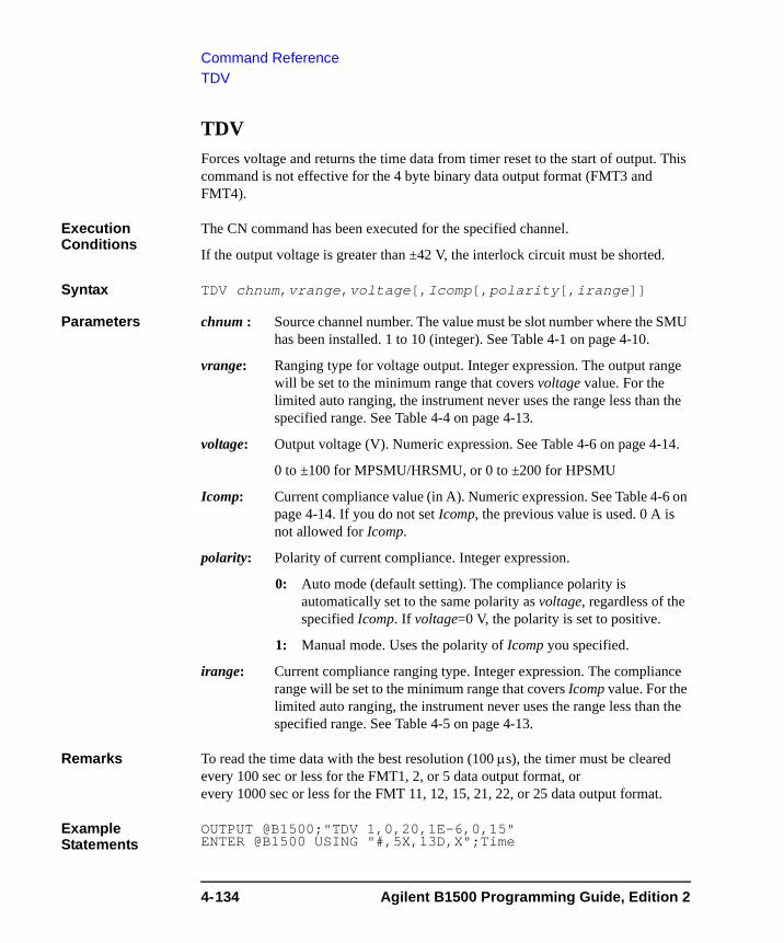
Command ReferenceTDV
TDVForces voltage and returns the time data from timer reset to the start of output. This command is not effective for the 4 byte binary data output format (FMT3 and FMT4).
Execution Conditions
The CN command has been executed for the specified channel.
If the output voltage is greater than ±42 V, the interlock circuit must be shorted.
Syntax TDV chnum,vrange,voltage[,Icomp[,polarity[,irange]]
Parameters chnum : Source channel number. The value must be slot number where the SMU has been installed. 1 to 10 (integer). See Table 4-1 on page 4-10.
vrange: Ranging type for voltage output. Integer expression. The output range will be set to the minimum range that covers voltage value. For the limited auto ranging, the instrument never uses the range less than the specified range. See Table 4-4 on page 4-13.
voltage: Output voltage (V). Numeric expression. See Table 4-6 on page 4-14.
0 to ±100 for MPSMU/HRSMU, or 0 to ±200 for HPSMU
Icomp: Current compliance value (in A). Numeric expression. See Table 4-6 on page 4-14. If you do not set Icomp, the previous value is used. 0 A is not allowed for Icomp.
polarity: Polarity of current compliance. Integer expression.
0: Auto mode (default setting). The compliance polarity is automatically set to the same polarity as voltage, regardless of the specified Icomp. If voltage=0 V, the polarity is set to positive.
1: Manual mode. Uses the polarity of Icomp you specified.
irange: Current compliance ranging type. Integer expression. The compliance range will be set to the minimum range that covers Icomp value. For the limited auto ranging, the instrument never uses the range less than the specified range. See Table 4-5 on page 4-13.
Remarks To read the time data with the best resolution (100 μs), the timer must be cleared every 100 sec or less for the FMT1, 2, or 5 data output format, or every 1000 sec or less for the FMT 11, 12, 15, 21, 22, or 25 data output format.
Example Statements
OUTPUT @B1500;"TDV 1,0,20,1E-6,0,15"ENTER @B1500 USING "#,5X,13D,X";Time
4-134 Agilent B1500 Programming Guide, Edition 2

Command ReferenceTGMO
TGMOThe TGMO command selects the edge trigger or the gate trigger for the Step Measurement Completion trigger output set by the TGP port,2,polarity,3 command. See Figure 4-2.
This command is available for the staircase sweep, multi channel sweep, and CV sweep measurements.
Syntax TGMO mode
Parameters mode : Edge trigger or gate trigger. Integer expression.
1: Edge trigger (initial setting).
2: Gate trigger.
Example Statements
OUTPUT @B1500;"TGMO 2"
See Also “TGP” and “TGPC”
Figure 4-2 Trigger Output Example, Staircase Sweep Measurement, Negative Logic
: Measurement
TGP t,2,p,3
XE
TGP t,2,p,2
TGP t,2,p,1
TGP t,2,p,3
TGP t,2,p,2
TGP t,2,p,1
Gate trigger
Edge trigger
Source trigger delay
Hold timeDelay time
Source trigger delay
Step delay time
Step Measurement Completion
Step Output Setup Completion
Measurement Completion
Step Measurement Completion
Step Output Setup Completion
Measurement Completion
Agilent B1500 Programming Guide, Edition 2 4-135
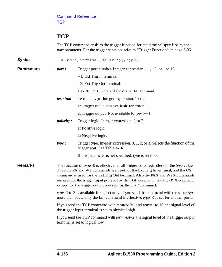
Command ReferenceTGP
TGPThe TGP command enables the trigger function for the terminal specified by the port parameter. For the trigger function, refer to “Trigger Function” on page 2-36.
Syntax TGP port,terminal,polarity[,type]
Parameters port : Trigger port number. Integer expression. -1, -2, or 1 to 16.
-1: Ext Trig In terminal.
-2: Ext Trig Out terminal.
1 to 16: Port 1 to 16 of the digital I/O terminal.
terminal : Terminal type. Integer expression. 1 or 2.
1: Trigger input. Not available for port=-2.
2: Trigger output. Not available for port=-1.
polarity : Trigger logic. Integer expression. 1 or 2.
1: Positive logic.
2: Negative logic.
type : Trigger type. Integer expression. 0, 1, 2, or 3. Selects the function of the trigger port. See Table 4-16.
If this parameter is not specified, type is set to 0.
Remarks The function of type=0 is effective for all trigger ports regardless of the type value. Then the PA and WS commands are used for the Ext Trig In terminal, and the OS command is used for the Ext Trig Out terminal. Also the PAX and WSX commands are used for the trigger input ports set by the TGP command, and the OSX command is used for the trigger output ports set by the TGP command.
type=1 to 3 is available for a port only. If you send the command with the same type more than once, only the last command is effective. type=0 is set for another ports.
If you send the TGP command with terminal=1 and port=1 to 16, the signal level of the trigger input terminal is set to physical high.
If you send the TGP command with terminal=2, the signal level of the trigger output terminal is set to logical low.
4-136 Agilent B1500 Programming Guide, Edition 2
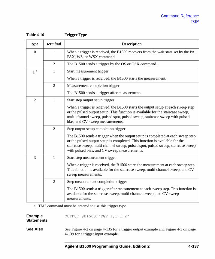
Command ReferenceTGP
Table 4-16 Trigger Type
Example Statements
OUTPUT @B1500;"TGP 1,1,1,2"
See Also See Figure 4-2 on page 4-135 for a trigger output example and Figure 4-3 on page 4-139 for a trigger input example.
type terminal Description
0 1 When a trigger is received, the B1500 recovers from the wait state set by the PA, PAX, WS, or WSX command.
2 The B1500 sends a trigger by the OS or OSX command.
1 a
a. TM3 command must be entered to use this trigger type.
1 Start measurement trigger
When a trigger is received, the B1500 starts the measurement.
2 Measurement completion trigger
The B1500 sends a trigger after measurement.
2 1 Start step output setup trigger
When a trigger is received, the B1500 starts the output setup at each sweep step or the pulsed output setup. This function is available for the staircase sweep, multi channel sweep, pulsed spot, pulsed sweep, staircase sweep with pulsed bias, and CV sweep measurements.
2 Step output setup completion trigger
The B1500 sends a trigger when the output setup is completed at each sweep step or the pulsed output setup is completed. This function is available for the staircase sweep, multi channel sweep, pulsed spot, pulsed sweep, staircase sweep with pulsed bias, and CV sweep measurements.
3 1 Start step measurement trigger
When a trigger is received, the B1500 starts the measurement at each sweep step. This function is available for the staircase sweep, multi channel sweep, and CV sweep measurements.
2 Step measurement completion trigger
The B1500 sends a trigger after measurement at each sweep step. This function is available for the staircase sweep, multi channel sweep, and CV sweep measurements.
Agilent B1500 Programming Guide, Edition 2 4-137
Command ReferenceTGPC
TGPCThe TGPC command clears the trigger setting of the specified ports.
Syntax TGPC [port[,port...[,port]...]]
A maximum of 18 ports can be set. If no port is specified, the TGPC command clears the setting of all ports; Ext Trig In, Ext Trig Out, and digital I/O ports 1 to 16.
Parameters port : Trigger port number. Integer expression. -1, -2, or 1 to 16.
-1: Ext Trig In terminal.
-2: Ext Trig Out terminal.
1 to 16: Port 1 to 16 of the digital I/O terminal.
Remarks The TGPC command sets the trigger ports as shown below.
Ext Trig In Same as after TGP -1,1,2,0 command execution.
Ext Trig Out Same as after TGP -2,2,2,0 command execution.
Digital I/O Ports No trigger function is available. The ERS? and ERC commands are available for the port control.
This is not same as the condition set by the *RST command that sets the ports as shown below.
Ext Trig In Same as after TGP -1,1,2,1 command execution.
Ext Trig Out Same as after TGP -2,2,2,1 command execution.
Digital I/O Ports No trigger function is available. The ERS? and ERC commands are available for the port control.
Example Statements
OUTPUT @B1500;"TGPC -1,-2,1,2"
See Also “TGP”
4-138 Agilent B1500 Programming Guide, Edition 2
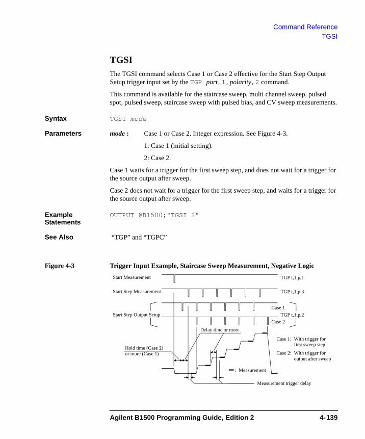
Command ReferenceTGSI
TGSIThe TGSI command selects Case 1 or Case 2 effective for the Start Step Output Setup trigger input set by the TGP port,1,polarity,2 command.
This command is available for the staircase sweep, multi channel sweep, pulsed spot, pulsed sweep, staircase sweep with pulsed bias, and CV sweep measurements.
Syntax TGSI mode
Parameters mode : Case 1 or Case 2. Integer expression. See Figure 4-3.
1: Case 1 (initial setting).
2: Case 2.
Case 1 waits for a trigger for the first sweep step, and does not wait for a trigger for the source output after sweep.
Case 2 does not wait for a trigger for the first sweep step, and waits for a trigger for the source output after sweep.
Example Statements
OUTPUT @B1500;"TGSI 2"
See Also “TGP” and “TGPC”
Figure 4-3 Trigger Input Example, Staircase Sweep Measurement, Negative Logic
: Measurement
TGP t,1,p,3
TGP t,1,p,2
TGP t,1,p,1
Hold time (Case 2)or more (Case 1)
Delay time or more
Start Step Measurement
Start Step Output Setup
Start Measurement
Measurement trigger delay
Case 1: With trigger for first sweep step
Case 2: With trigger for output after sweep
Case 1
Case 2
Agilent B1500 Programming Guide, Edition 2 4-139
Command ReferenceTGSO
TGSOThe TGSO command selects the edge trigger or the gate trigger for the Step Output Setup Completion trigger output set by the TGP port,2,polarity,2 command. See Figure 4-2 on page 4-135
This command is available for the staircase sweep, multi channel sweep, pulsed spot, pulsed sweep, staircase sweep with pulsed bias, and CV sweep measurements.
Syntax TGSO mode
Parameters mode : Edge trigger or gate trigger. Integer expression.
1: Edge trigger (initial setting).
2: Gate trigger.
Example Statements
OUTPUT @B1500;"TGSO 2"
See Also “TGP” and “TGPC”
TGXOThe TGXO command selects the edge trigger or the gate trigger for the Measurement Completion trigger output set by the TGP port,2,polarity,1 command. See Figure 4-2 on page 4-135
Syntax TGXO mode
Parameters mode : Edge trigger or gate trigger. Integer expression.
1: Edge trigger (initial setting).
2: Gate trigger.
Example Statements
OUTPUT @B1500;"TGXO 2"
See Also “TGP” and “TGPC”
4-140 Agilent B1500 Programming Guide, Edition 2

Command ReferenceTI
TIThe TI command performs the high speed spot measurement, and returns the measurement data. The command starts a current measurement regardless of the SMU operation mode, trigger mode (TM command), and measurement mode (MM command).
Execution Conditions
CN command has been executed for the specified channel.
Syntax TI chnum[,range]
Parameters chnum : Measurement channel number. The value must be slot number where the SMU has been installed. Integer expression. 1 to 10. See Table 4-1 on page 4-10.
range : Measurement range or ranging type. Integer expression. See Table 4-3 on page 4-12.
If you select the fixed range, the instrument performs measurement by using the specified range.
For the auto or limited auto ranging, the measurement range will be set to the minimum range that covers the measured values. However, the instrument never uses the range less than the specified range for the limited auto ranging.
If you do not specify the range parameter for voltage output channels, the channel uses the minimum range that covers the compliance value.
The range parameter is meaningless for current output channels. The measurement ranging type is always same as the output ranging type.
Example Statements
OUTPUT @B1500;"TI 1" ENTER @B1500 USING "#,3X,12D,X";Idata
Agilent B1500 Programming Guide, Edition 2 4-141
Command ReferenceTM
TM The TM command specifies how events are effective for the following actions:
• Releasing the B1500 from the paused status set by the PA or PAX command
• Starting the measurement except for high speed spot measurement (when the B1500 is not in the paused status set by the PA, PAX, WS, or WSX command)
Syntax TM mode
Parameters mode : Event mode. Integer expression. See below.
To enable the trigger function set by the TGP port,terminal,polarity,1 command, the mode value must be 3.
Remarks In the TM3 event mode, if the B1500 is not in the wait status set by the PA, PAX, WS, or WSX command, the B1500 can start the measurement by an external trigger input. After measurement, the B1500 sends a trigger to a trigger output terminal. In the initial setting, you can use the Ext Trig In and Out terminals. To use the digital I/O port, enter the TGP command to set the trigger input or output terminal.
To set the trigger logic (initial setting: negative), send the TGP command for the trigger input terminal.
Example Statements
OUTPUT @B1500;"TM 1"
OUTPUT @B1500;"TM 3"
See Also “PA”, “PAX”, “TGP”, “TGPC”, “WS”, and “WSX”
mode Events
1 XE command and GPIB GET (Group Execute Trigger, TRIGGER command in HP BASIC). Initial setting.
2 XE command
3 XE command and external trigger
4 XE command and MM command (automatic trigger after the MM command execution)
4-142 Agilent B1500 Programming Guide, Edition 2
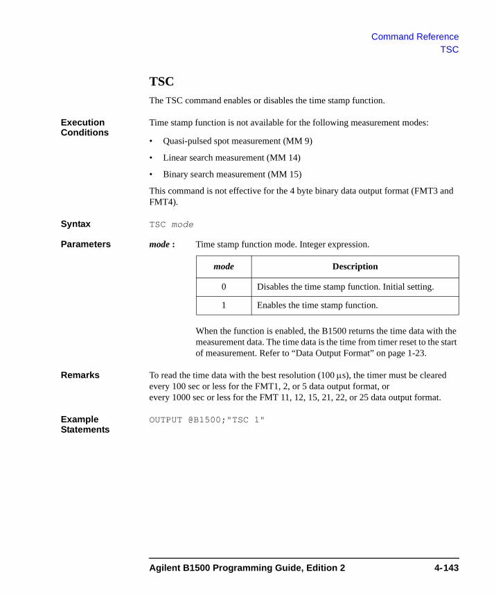
Command ReferenceTSC
TSCThe TSC command enables or disables the time stamp function.
Execution Conditions
Time stamp function is not available for the following measurement modes:
• Quasi-pulsed spot measurement (MM 9)
• Linear search measurement (MM 14)
• Binary search measurement (MM 15)
This command is not effective for the 4 byte binary data output format (FMT3 and FMT4).
Syntax TSC mode
Parameters mode : Time stamp function mode. Integer expression.
When the function is enabled, the B1500 returns the time data with the measurement data. The time data is the time from timer reset to the start of measurement. Refer to “Data Output Format” on page 1-23.
Remarks To read the time data with the best resolution (100 μs), the timer must be cleared every 100 sec or less for the FMT1, 2, or 5 data output format, or every 1000 sec or less for the FMT 11, 12, 15, 21, 22, or 25 data output format.
Example Statements
OUTPUT @B1500;"TSC 1"
mode Description
0 Disables the time stamp function. Initial setting.
1 Enables the time stamp function.
Agilent B1500 Programming Guide, Edition 2 4-143
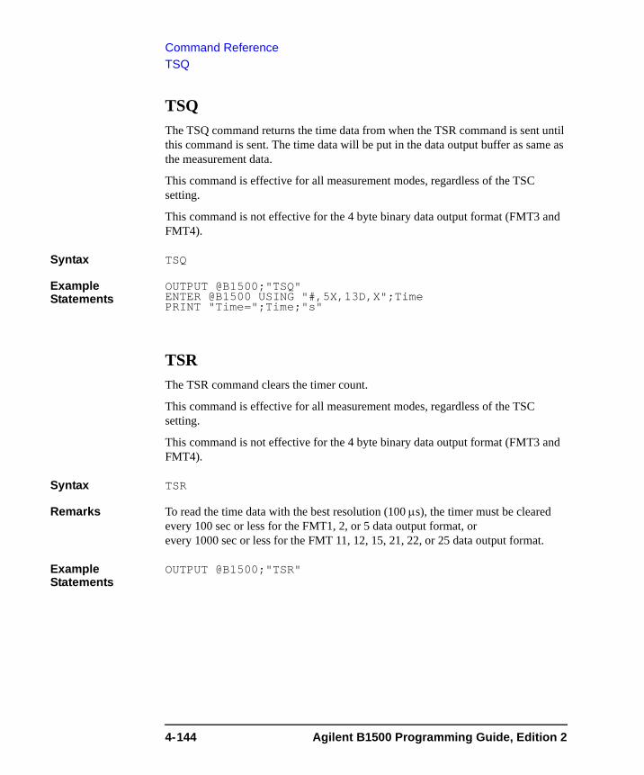
Command ReferenceTSQ
TSQThe TSQ command returns the time data from when the TSR command is sent until this command is sent. The time data will be put in the data output buffer as same as the measurement data.
This command is effective for all measurement modes, regardless of the TSC setting.
This command is not effective for the 4 byte binary data output format (FMT3 and FMT4).
Syntax TSQ
Example Statements
OUTPUT @B1500;"TSQ"ENTER @B1500 USING "#,5X,13D,X";TimePRINT "Time=";Time;"s"
TSRThe TSR command clears the timer count.
This command is effective for all measurement modes, regardless of the TSC setting.
This command is not effective for the 4 byte binary data output format (FMT3 and FMT4).
Syntax TSR
Remarks To read the time data with the best resolution (100 μs), the timer must be cleared every 100 sec or less for the FMT1, 2, or 5 data output format, or every 1000 sec or less for the FMT 11, 12, 15, 21, 22, or 25 data output format.
Example Statements
OUTPUT @B1500;"TSR"
4-144 Agilent B1500 Programming Guide, Edition 2
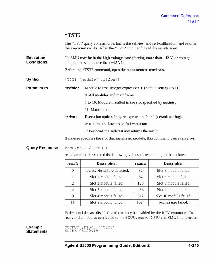
Command Reference*TST?
*TST? The *TST? query command performs the self-test and self-calibration, and returns the execution results. After the *TST? command, read the results soon.
Execution Conditions
No SMU may be in the high voltage state (forcing more than ±42 V, or voltage compliance set to more than ±42 V).
Before the *TST? command, open the measurement terminals.
Syntax *TST? [module[,option]]
Parameters module : Module to test. Integer expression. 0 (default setting) to 11.
0: All modules and mainframe.
1 to 10: Module installed in the slot specified by module.
11: Mainframe.
option : Execution option. Integer expression. 0 or 1 (default setting).
0: Returns the latest pass/fail condition.
1: Performs the self-test and returns the result.
If module specifies the slot that installs no module, this command causes an error.
Query Response results<CR/LF^EOI>
results returns the sum of the following values corresponding to the failures.
Failed modules are disabled, and can only be enabled by the RCV command. To recover the modules connected to the SCUU, recover CMU and SMU in this order.
Example Statements
OUTPUT @B1500;"*TST?" ENTER @B1500;A
results Description results Description
0 Passed. No failure detected. 32 Slot 6 module failed.1 Slot 1 module failed. 64 Slot 7 module failed.2 Slot 2 module failed. 128 Slot 8 module failed.4 Slot 3 module failed. 256 Slot 9 module failed.8 Slot 4 module failed. 512 Slot 10 module failed.
16 Slot 5 module failed. 1024 Mainframe failed.
Agilent B1500 Programming Guide, Edition 2 4-145
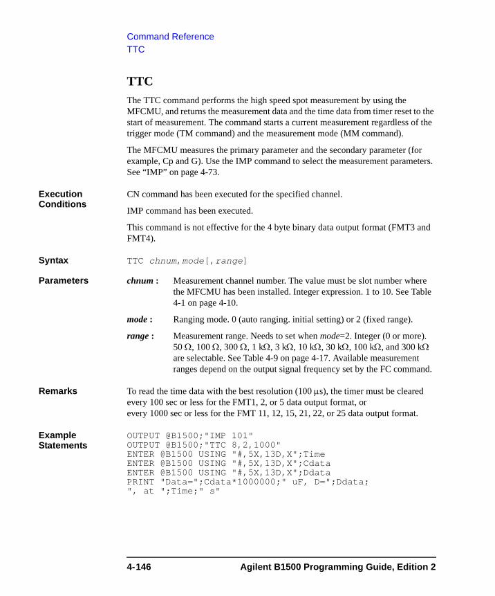
Command ReferenceTTC
TTCThe TTC command performs the high speed spot measurement by using the MFCMU, and returns the measurement data and the time data from timer reset to the start of measurement. The command starts a current measurement regardless of the trigger mode (TM command) and the measurement mode (MM command).
The MFCMU measures the primary parameter and the secondary parameter (for example, Cp and G). Use the IMP command to select the measurement parameters. See “IMP” on page 4-73.
Execution Conditions
CN command has been executed for the specified channel.
IMP command has been executed.
This command is not effective for the 4 byte binary data output format (FMT3 and FMT4).
Syntax TTC chnum,mode[,range]
Parameters chnum : Measurement channel number. The value must be slot number where the MFCMU has been installed. Integer expression. 1 to 10. See Table 4-1 on page 4-10.
mode : Ranging mode. 0 (auto ranging. initial setting) or 2 (fixed range).
range : Measurement range. Needs to set when mode=2. Integer (0 or more). 50 Ω, 100 Ω, 300 Ω, 1 kΩ, 3 kΩ, 10 kΩ, 30 kΩ, 100 kΩ, and 300 kΩ are selectable. See Table 4-9 on page 4-17. Available measurement ranges depend on the output signal frequency set by the FC command.
Remarks To read the time data with the best resolution (100 μs), the timer must be cleared every 100 sec or less for the FMT1, 2, or 5 data output format, or every 1000 sec or less for the FMT 11, 12, 15, 21, 22, or 25 data output format.
Example Statements
OUTPUT @B1500;"IMP 101"OUTPUT @B1500;"TTC 8,2,1000"ENTER @B1500 USING "#,5X,13D,X";TimeENTER @B1500 USING "#,5X,13D,X";CdataENTER @B1500 USING "#,5X,13D,X";DdataPRINT "Data=";Cdata*1000000;" uF, D=";Ddata; ", at ";Time;" s"
4-146 Agilent B1500 Programming Guide, Edition 2
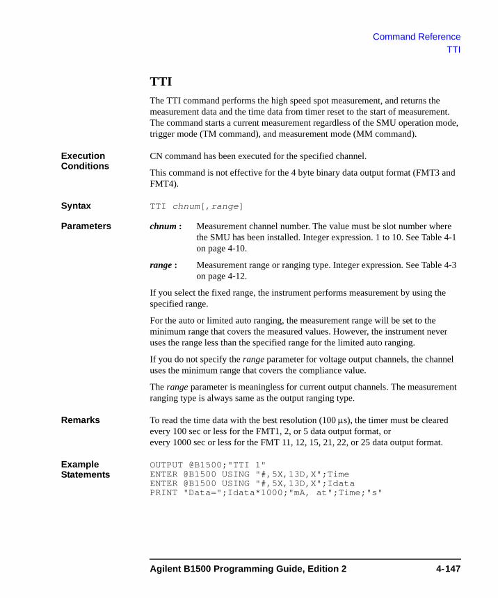
Command ReferenceTTI
TTI The TTI command performs the high speed spot measurement, and returns the measurement data and the time data from timer reset to the start of measurement. The command starts a current measurement regardless of the SMU operation mode, trigger mode (TM command), and measurement mode (MM command).
Execution Conditions
CN command has been executed for the specified channel.
This command is not effective for the 4 byte binary data output format (FMT3 and FMT4).
Syntax TTI chnum[,range]
Parameters chnum : Measurement channel number. The value must be slot number where the SMU has been installed. Integer expression. 1 to 10. See Table 4-1 on page 4-10.
range : Measurement range or ranging type. Integer expression. See Table 4-3 on page 4-12.
If you select the fixed range, the instrument performs measurement by using the specified range.
For the auto or limited auto ranging, the measurement range will be set to the minimum range that covers the measured values. However, the instrument never uses the range less than the specified range for the limited auto ranging.
If you do not specify the range parameter for voltage output channels, the channel uses the minimum range that covers the compliance value.
The range parameter is meaningless for current output channels. The measurement ranging type is always same as the output ranging type.
Remarks To read the time data with the best resolution (100 μs), the timer must be cleared every 100 sec or less for the FMT1, 2, or 5 data output format, or every 1000 sec or less for the FMT 11, 12, 15, 21, 22, or 25 data output format.
Example Statements
OUTPUT @B1500;"TTI 1"ENTER @B1500 USING "#,5X,13D,X";TimeENTER @B1500 USING "#,5X,13D,X";IdataPRINT "Data=";Idata*1000;"mA, at";Time;"s"
Agilent B1500 Programming Guide, Edition 2 4-147
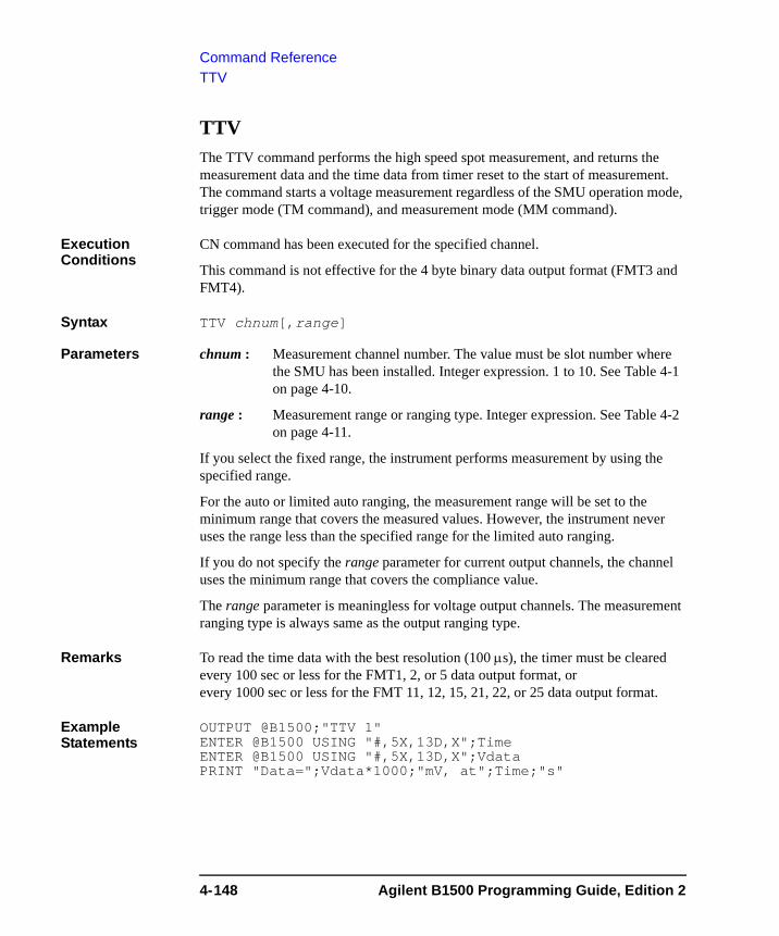
Command ReferenceTTV
TTV The TTV command performs the high speed spot measurement, and returns the measurement data and the time data from timer reset to the start of measurement. The command starts a voltage measurement regardless of the SMU operation mode, trigger mode (TM command), and measurement mode (MM command).
Execution Conditions
CN command has been executed for the specified channel.
This command is not effective for the 4 byte binary data output format (FMT3 and FMT4).
Syntax TTV chnum[,range]
Parameters chnum : Measurement channel number. The value must be slot number where the SMU has been installed. Integer expression. 1 to 10. See Table 4-1 on page 4-10.
range : Measurement range or ranging type. Integer expression. See Table 4-2 on page 4-11.
If you select the fixed range, the instrument performs measurement by using the specified range.
For the auto or limited auto ranging, the measurement range will be set to the minimum range that covers the measured values. However, the instrument never uses the range less than the specified range for the limited auto ranging.
If you do not specify the range parameter for current output channels, the channel uses the minimum range that covers the compliance value.
The range parameter is meaningless for voltage output channels. The measurement ranging type is always same as the output ranging type.
Remarks To read the time data with the best resolution (100 μs), the timer must be cleared every 100 sec or less for the FMT1, 2, or 5 data output format, or every 1000 sec or less for the FMT 11, 12, 15, 21, 22, or 25 data output format.
Example Statements
OUTPUT @B1500;"TTV 1"ENTER @B1500 USING "#,5X,13D,X";TimeENTER @B1500 USING "#,5X,13D,X";VdataPRINT "Data=";Vdata*1000;"mV, at";Time;"s"
4-148 Agilent B1500 Programming Guide, Edition 2
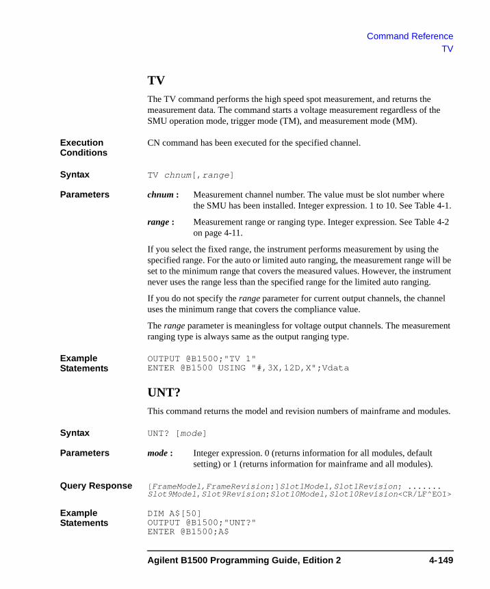
Command ReferenceTV
TVThe TV command performs the high speed spot measurement, and returns the measurement data. The command starts a voltage measurement regardless of the SMU operation mode, trigger mode (TM), and measurement mode (MM).
Execution Conditions
CN command has been executed for the specified channel.
Syntax TV chnum[,range]
Parameters chnum : Measurement channel number. The value must be slot number where the SMU has been installed. Integer expression. 1 to 10. See Table 4-1.
range : Measurement range or ranging type. Integer expression. See Table 4-2 on page 4-11.
If you select the fixed range, the instrument performs measurement by using the specified range. For the auto or limited auto ranging, the measurement range will be set to the minimum range that covers the measured values. However, the instrument never uses the range less than the specified range for the limited auto ranging.
If you do not specify the range parameter for current output channels, the channel uses the minimum range that covers the compliance value.
The range parameter is meaningless for voltage output channels. The measurement ranging type is always same as the output ranging type.
Example Statements
OUTPUT @B1500;"TV 1" ENTER @B1500 USING "#,3X,12D,X";Vdata
UNT? This command returns the model and revision numbers of mainframe and modules.
Syntax UNT? [mode]
Parameters mode : Integer expression. 0 (returns information for all modules, default setting) or 1 (returns information for mainframe and all modules).
Query Response [FrameModel,FrameRevision;]Slot1Model,Slot1Revision; ....... Slot9Model,Slot9Revision;Slot10Model,Slot10Revision<CR/LF^EOI>
Example Statements
DIM A$[50]OUTPUT @B1500;"UNT?" ENTER @B1500;A$
Agilent B1500 Programming Guide, Edition 2 4-149
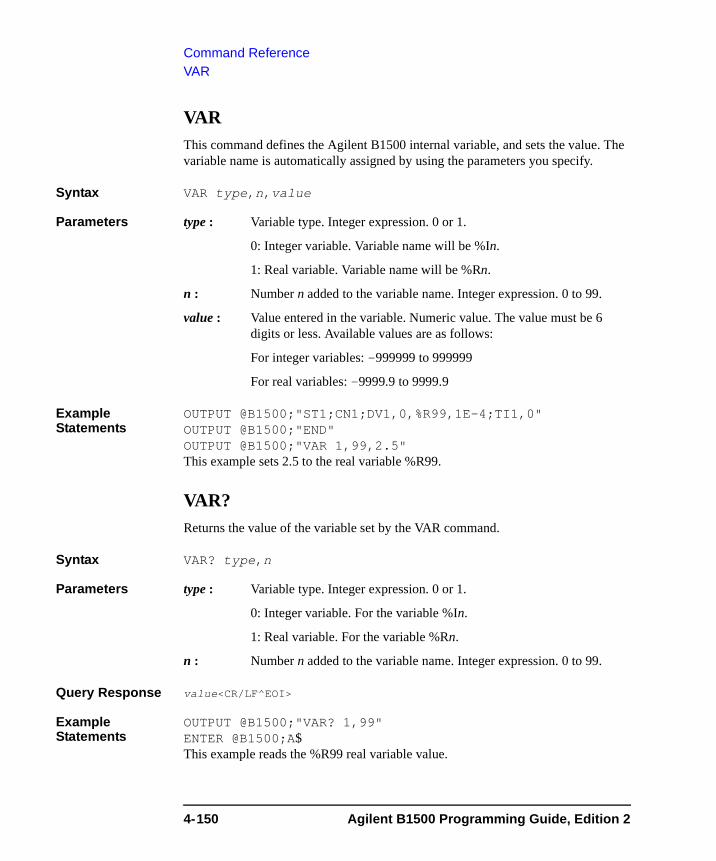
Command ReferenceVAR
VARThis command defines the Agilent B1500 internal variable, and sets the value. The variable name is automatically assigned by using the parameters you specify.
Syntax VAR type,n,value
Parameters type : Variable type. Integer expression. 0 or 1.
0: Integer variable. Variable name will be %In.
1: Real variable. Variable name will be %Rn.
n : Number n added to the variable name. Integer expression. 0 to 99.
value : Value entered in the variable. Numeric value. The value must be 6 digits or less. Available values are as follows:
For integer variables: -999999 to 999999
For real variables: -9999.9 to 9999.9
Example Statements
OUTPUT @B1500;"ST1;CN1;DV1,0,%R99,1E-4;TI1,0"OUTPUT @B1500;"END"OUTPUT @B1500;"VAR 1,99,2.5"This example sets 2.5 to the real variable %R99.
VAR?Returns the value of the variable set by the VAR command.
Syntax VAR? type,n
Parameters type : Variable type. Integer expression. 0 or 1.
0: Integer variable. For the variable %In.
1: Real variable. For the variable %Rn.
n : Number n added to the variable name. Integer expression. 0 to 99.
Query Response value<CR/LF^EOI>
Example Statements
OUTPUT @B1500;"VAR? 1,99"ENTER @B1500;A$This example reads the %R99 real variable value.
4-150 Agilent B1500 Programming Guide, Edition 2
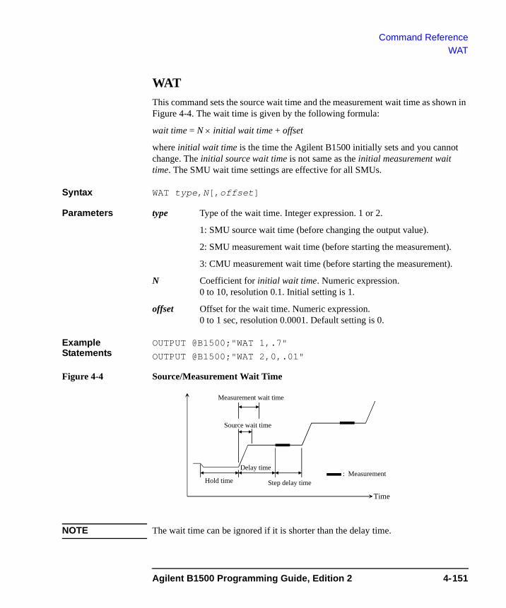
Command ReferenceWAT
WATThis command sets the source wait time and the measurement wait time as shown in Figure 4-4. The wait time is given by the following formula:
wait time = N × initial wait time + offset
where initial wait time is the time the Agilent B1500 initially sets and you cannot change. The initial source wait time is not same as the initial measurement wait time. The SMU wait time settings are effective for all SMUs.
Syntax WAT type,N[,offset]
Parameters type Type of the wait time. Integer expression. 1 or 2.
1: SMU source wait time (before changing the output value).
2: SMU measurement wait time (before starting the measurement).
3: CMU measurement wait time (before starting the measurement).
N Coefficient for initial wait time. Numeric expression. 0 to 10, resolution 0.1. Initial setting is 1.
offset Offset for the wait time. Numeric expression. 0 to 1 sec, resolution 0.0001. Default setting is 0.
Example Statements
OUTPUT @B1500;"WAT 1,.7"
OUTPUT @B1500;"WAT 2,0,.01"
Figure 4-4 Source/Measurement Wait Time
NOTE The wait time can be ignored if it is shorter than the delay time.
Measurement wait time
Time
: MeasurementHold time
Delay time
Source wait time
Step delay time
Agilent B1500 Programming Guide, Edition 2 4-151
Command ReferenceWAT
NOTE It is not easy to determine the best wait time. If you specify it too short, the measurement may start before device characteristics stable. If too long, time will be wasted.
The initial wait time may be too short for measurements of high capacitance or slow response devices. Then set the wait time longer.
For measurements of low capacitance or fast response devices, if measurement speed has top priority or is more important than reliability and accuracy, set the wait time shorter.
4-152 Agilent B1500 Programming Guide, Edition 2
Command ReferenceWDCV
WDCVThis command sets the staircase sweep voltage source used for the CV sweep measurement (MM18). The sweep source will be the MFCMU, or the SMU that can be connected to the Force1/Sense1 terminals of the SCUU (SMU CMU unify unit).
Execution Conditions
The CN command has been executed for the specified channel.
If you want to apply DC voltage over ±25 V, the SCUU must be connected correctly. The SCUU can be used with the MFCMU and two SMUs (MPSMU or HRSMU). The SCUU cannot be used if the HPSMU is connected to the SCUU or if the number of SMUs connected to the SCUU is only one.
If the output voltage is greater than ±42 V, the interlock circuit must be shorted.
Syntax WDCV chnum,mode,start,stop,step
Parameters chnum : Source channel number. The value must be slot number where the MFCMU has been installed. Integer expression. 1 to 10. See Table 4-1 on page 4-10.
mode : Sweep mode. Integer expression.
1: Linear sweep (single stair, start to stop.)
2: Log sweep (single stair, start to stop.)
3: Linear sweep (double stair, start to stop to start.)
4: Log sweep (double stair, start to stop to start.)
start, stop : Start or stop voltage (in V). Numeric expression. start and stop must have the same polarity for log sweep.
0 (initial setting) to ±100 V
With the SCUU, the source module is automatically selected by the setting value. The MFCMU is used if the voltage from start to stop is below ±25 V (setting resolution: 0.001 V), or the SMU is used if it is greater than ±25 V (setting resolution: 0.005 V).
The SMU will operate with the 100 V limited auto ranging and 20 mA compliance settings.
step : Number of steps for staircase sweep. Numeric expression. 1 to 1001.
Example Statements
OUTPUT @B1500;"WDCV 8,1,5,-5,101"
Agilent B1500 Programming Guide, Edition 2 4-153
Command ReferenceWI
WI The WI command specifies the staircase sweep current source and its parameters. This command also clears the WV, WSV, WSI, and WNX command settings.
This command setting is cleared by the WV command.
Syntax • For Staircase Sweep Measurement:
WI chnum,mode,range,start,stop,step[,Vcomp[,Pcomp]]
• For Staircase Sweep with Pulsed Bias Measurement:
WI chnum,mode,range,start,stop,step[,Vcomp]
Parameters chnum : Sweep source channel number. The value must be slot number where the SMU has been installed. Integer expression. 1 to 10. See Table 4-1 on page 4-10.
mode : Sweep mode. Integer expression. Only linear sweep (mode=1 or 3) is available for the staircase sweep with pulsed bias.
1: Linear sweep (single stair, start to stop.)
2: Log sweep (single stair, start to stop.)
3: Linear sweep (double stair, start to stop to start.)
4: Log sweep (double stair, start to stop to start.)
range : Ranging type for staircase sweep current output. Integer expression. See Table 4-5 on page 4-13.
For the linear sweep, the B1500 uses the minimum range that covers both start and stop values to force the staircase sweep current.
For the log sweep, the B1500 uses the minimum range that covers the output value, and changes the output range dynamically.
For the limited auto ranging, the instrument never uses the range less than the specified range.
start, stop : Start or stop current (in A). Numeric expression. See Table 4-7 on page 4-15. start and stop must have the same polarity for log sweep.
0 to ±0.1 for MPSMU/HRSMU, or 0 to ±1 for HPSMU
4-154 Agilent B1500 Programming Guide, Edition 2
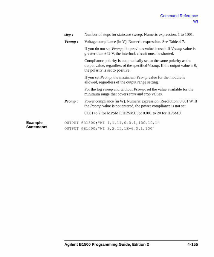
Command ReferenceWI
step : Number of steps for staircase sweep. Numeric expression. 1 to 1001.
Vcomp : Voltage compliance (in V). Numeric expression. See Table 4-7.
If you do not set Vcomp, the previous value is used. If Vcomp value is greater than ±42 V, the interlock circuit must be shorted.
Compliance polarity is automatically set to the same polarity as the output value, regardless of the specified Vcomp. If the output value is 0, the polarity is set to positive.
If you set Pcomp, the maximum Vcomp value for the module is allowed, regardless of the output range setting.
For the log sweep and without Pcomp, set the value available for the minimum range that covers start and stop values.
Pcomp : Power compliance (in W). Numeric expression. Resolution: 0.001 W. If the Pcomp value is not entered, the power compliance is not set.
0.001 to 2 for MPSMU/HRSMU, or 0.001 to 20 for HPSMU
Example Statements
OUTPUT @B1500;"WI 1,1,11,0,0.1,100,10,1"
OUTPUT @B1500;"WI 2,2,15,1E−6,0.1,100"
Agilent B1500 Programming Guide, Edition 2 4-155
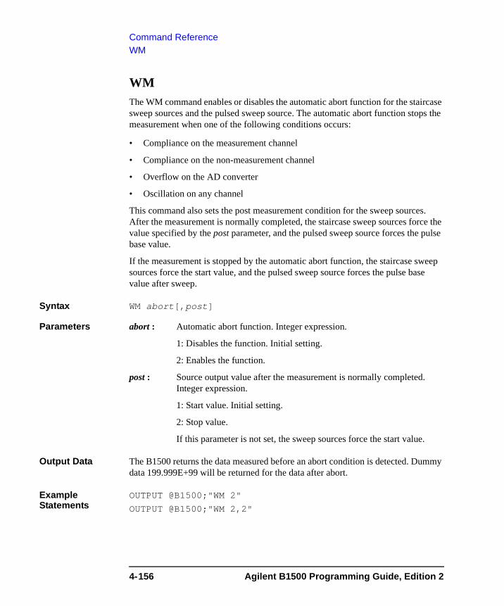
Command ReferenceWM
WM The WM command enables or disables the automatic abort function for the staircase sweep sources and the pulsed sweep source. The automatic abort function stops the measurement when one of the following conditions occurs:
• Compliance on the measurement channel
• Compliance on the non-measurement channel
• Overflow on the AD converter
• Oscillation on any channel
This command also sets the post measurement condition for the sweep sources. After the measurement is normally completed, the staircase sweep sources force the value specified by the post parameter, and the pulsed sweep source forces the pulse base value.
If the measurement is stopped by the automatic abort function, the staircase sweep sources force the start value, and the pulsed sweep source forces the pulse base value after sweep.
Syntax WM abort[,post]
Parameters abort : Automatic abort function. Integer expression.
1: Disables the function. Initial setting.
2: Enables the function.
post : Source output value after the measurement is normally completed. Integer expression.
1: Start value. Initial setting.
2: Stop value.
If this parameter is not set, the sweep sources force the start value.
Output Data The B1500 returns the data measured before an abort condition is detected. Dummy data 199.999E+99 will be returned for the data after abort.
Example Statements
OUTPUT @B1500;"WM 2"
OUTPUT @B1500;"WM 2,2"
4-156 Agilent B1500 Programming Guide, Edition 2

Command ReferenceWMDCV
WMDCVThis command enables or disables the automatic abort function for the CV sweep measurement (MM18). The automatic abort function stops the measurement when one of the following conditions occurs:
• NULL loop unbalance condition
• IV amplifier saturation condition
• Overflow on the AD converter
This command also sets the post measurement condition for the source. After the measurement is normally completed, the voltage source forces the value specified by the post parameter.
If the measurement is stopped by the automatic abort function, the voltage source forces the start value.
Syntax WMDCV abort[,post]
Parameters abort : Automatic abort function. Integer expression.
1: Disables the function. Initial setting.
2: Enables the function.
post : Source output value after the measurement is normally completed. Integer expression.
1: Start value. Initial setting.
2: Stop value.
If this parameter is not set, the voltage source forces the start value.
Output Data The B1500 returns the data measured before an abort condition is detected. Dummy data 199.999E+99 will be returned for the data after abort.
Example Statements
OUTPUT @B1500;"WMDCV 2"
OUTPUT @B1500;"WMDCV 2,2"
Agilent B1500 Programming Guide, Edition 2 4-157
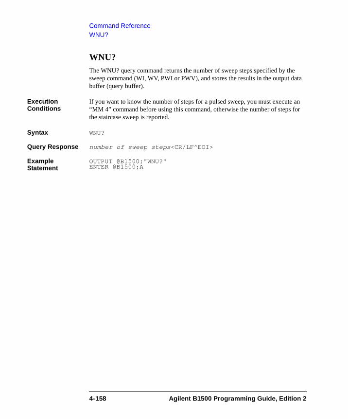
Command ReferenceWNU?
WNU? The WNU? query command returns the number of sweep steps specified by the sweep command (WI, WV, PWI or PWV), and stores the results in the output data buffer (query buffer).
Execution Conditions
If you want to know the number of steps for a pulsed sweep, you must execute an “MM 4” command before using this command, otherwise the number of steps for the staircase sweep is reported.
Syntax WNU?
Query Response number of sweep steps<CR/LF^EOI>
Example Statement
OUTPUT @B1500;"WNU?"ENTER @B1500;A
4-158 Agilent B1500 Programming Guide, Edition 2
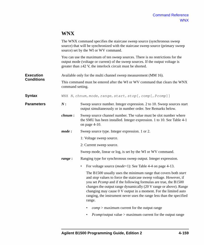
Command ReferenceWNX
WNXThe WNX command specifies the staircase sweep source (synchronous sweep source) that will be synchronized with the staircase sweep source (primary sweep source) set by the WI or WV command.
You can use the maximum of ten sweep sources. There is no restrictions for the output mode (voltage or current) of the sweep sources. If the output voltage is greater than ±42 V, the interlock circuit must be shorted.
Execution Conditions
Available only for the multi channel sweep measurement (MM 16).
This command must be entered after the WI or WV command that clears the WNX command setting.
Syntax WNX N,chnum,mode,range,start,stop[,comp[,Pcomp]]
Parameters N : Sweep source number. Integer expression. 2 to 10. Sweep sources start output simultaneously or in number order. See Remarks below.
chnum : Sweep source channel number. The value must be slot number where the SMU has been installed. Integer expression. 1 to 10. See Table 4-1 on page 4-10.
mode : Sweep source type. Integer expression. 1 or 2.
1: Voltage sweep source.
2: Current sweep source.
Sweep mode, linear or log, is set by the WI or WV command.
range : Ranging type for synchronous sweep output. Integer expression.
• For voltage source (mode=1): See Table 4-4 on page 4-13.
The B1500 usually uses the minimum range that covers both start and stop values to force the staircase sweep voltage. However, if you set Pcomp and if the following formulas are true, the B1500 changes the output range dynamically (20 V range or above). Range changing may cause 0 V output in a moment. For the limited auto ranging, the instrument never uses the range less than the specified range.
• comp > maximum current for the output range
• Pcomp/output value > maximum current for the output range
Agilent B1500 Programming Guide, Edition 2 4-159
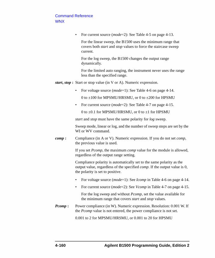
Command ReferenceWNX
• For current source (mode=2): See Table 4-5 on page 4-13.
For the linear sweep, the B1500 uses the minimum range that covers both start and stop values to force the staircase sweep current.
For the log sweep, the B1500 changes the output range dynamically.
For the limited auto ranging, the instrument never uses the range less than the specified range.
start, stop : Start or stop value (in V or A). Numeric expression.
• For voltage source (mode=1): See Table 4-6 on page 4-14.
0 to ±100 for MPSMU/HRSMU, or 0 to ±200 for HPSMU
• For current source (mode=2): See Table 4-7 on page 4-15.
0 to ±0.1 for MPSMU/HRSMU, or 0 to ±1 for HPSMU
start and stop must have the same polarity for log sweep.
Sweep mode, linear or log, and the number of sweep steps are set by the WI or WV command.
comp : Compliance (in A or V). Numeric expression. If you do not set comp, the previous value is used.
If you set Pcomp, the maximum comp value for the module is allowed, regardless of the output range setting.
Compliance polarity is automatically set to the same polarity as the output value, regardless of the specified comp. If the output value is 0, the polarity is set to positive.
• For voltage source (mode=1): See Icomp in Table 4-6 on page 4-14.
• For current source (mode=2): See Vcomp in Table 4-7 on page 4-15.
For the log sweep and without Pcomp, set the value available for the minimum range that covers start and stop values.
Pcomp : Power compliance (in W). Numeric expression. Resolution: 0.001 W. If the Pcomp value is not entered, the power compliance is not set.
0.001 to 2 for MPSMU/HRSMU, or 0.001 to 20 for HPSMU
4-160 Agilent B1500 Programming Guide, Edition 2
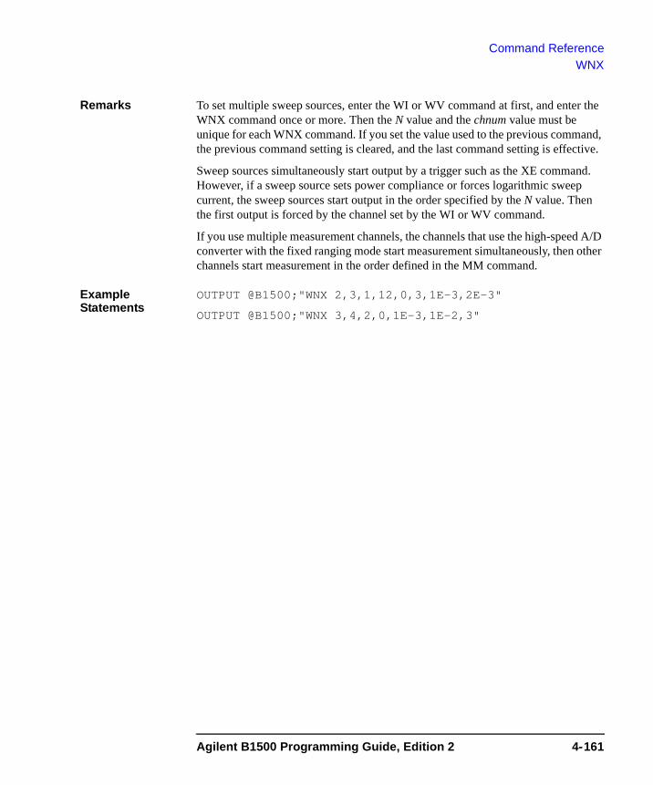
Command ReferenceWNX
Remarks To set multiple sweep sources, enter the WI or WV command at first, and enter the WNX command once or more. Then the N value and the chnum value must be unique for each WNX command. If you set the value used to the previous command, the previous command setting is cleared, and the last command setting is effective.
Sweep sources simultaneously start output by a trigger such as the XE command. However, if a sweep source sets power compliance or forces logarithmic sweep current, the sweep sources start output in the order specified by the N value. Then the first output is forced by the channel set by the WI or WV command.
If you use multiple measurement channels, the channels that use the high-speed A/D converter with the fixed ranging mode start measurement simultaneously, then other channels start measurement in the order defined in the MM command.
Example Statements
OUTPUT @B1500;"WNX 2,3,1,12,0,3,1E-3,2E-3"
OUTPUT @B1500;"WNX 3,4,2,0,1E-3,1E-2,3"
Agilent B1500 Programming Guide, Edition 2 4-161
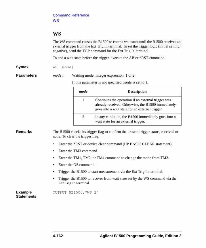
Command ReferenceWS
WS The WS command causes the B1500 to enter a wait state until the B1500 receives an external trigger from the Ext Trig In terminal. To set the trigger logic (initial setting: negative), send the TGP command for the Ext Trig In terminal.
To end a wait state before the trigger, execute the AB or *RST command.
Syntax WS [mode]
Parameters mode : Waiting mode. Integer expression. 1 or 2.
If this parameter is not specified, mode is set to 1.
Remarks The B1500 checks its trigger flag to confirm the present trigger status, received or none. To clear the trigger flag:
• Enter the *RST or device clear command (HP BASIC CLEAR statement).
• Enter the TM3 command.
• Enter the TM1, TM2, or TM4 command to change the mode from TM3.
• Enter the OS command.
• Trigger the B1500 to start measurement via the Ext Trig In terminal.
• Trigger the B1500 to recover from wait state set by the WS command via the Ext Trig In terminal.
Example Statements
OUTPUT @B1500;"WS 2"
mode Description
1 Continues the operation if an external trigger was already received. Otherwise, the B1500 immediately goes into a wait state for an external trigger.
2 In any condition, the B1500 immediately goes into a wait state for an external trigger.
4-162 Agilent B1500 Programming Guide, Edition 2
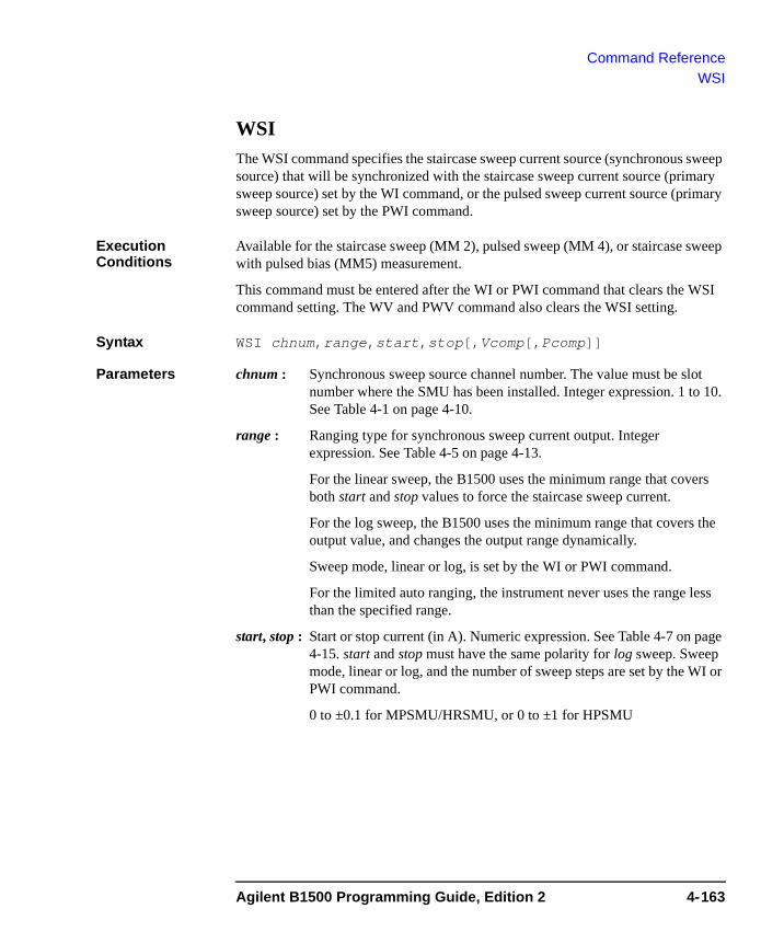
Command ReferenceWSI
WSIThe WSI command specifies the staircase sweep current source (synchronous sweep source) that will be synchronized with the staircase sweep current source (primary sweep source) set by the WI command, or the pulsed sweep current source (primary sweep source) set by the PWI command.
Execution Conditions
Available for the staircase sweep (MM 2), pulsed sweep (MM 4), or staircase sweep with pulsed bias (MM5) measurement.
This command must be entered after the WI or PWI command that clears the WSI command setting. The WV and PWV command also clears the WSI setting.
Syntax WSI chnum,range,start,stop[,Vcomp[,Pcomp]]
Parameters chnum : Synchronous sweep source channel number. The value must be slot number where the SMU has been installed. Integer expression. 1 to 10. See Table 4-1 on page 4-10.
range : Ranging type for synchronous sweep current output. Integer expression. See Table 4-5 on page 4-13.
For the linear sweep, the B1500 uses the minimum range that covers both start and stop values to force the staircase sweep current.
For the log sweep, the B1500 uses the minimum range that covers the output value, and changes the output range dynamically.
Sweep mode, linear or log, is set by the WI or PWI command.
For the limited auto ranging, the instrument never uses the range less than the specified range.
start, stop : Start or stop current (in A). Numeric expression. See Table 4-7 on page 4-15. start and stop must have the same polarity for log sweep. Sweep mode, linear or log, and the number of sweep steps are set by the WI or PWI command.
0 to ±0.1 for MPSMU/HRSMU, or 0 to ±1 for HPSMU
Agilent B1500 Programming Guide, Edition 2 4-163
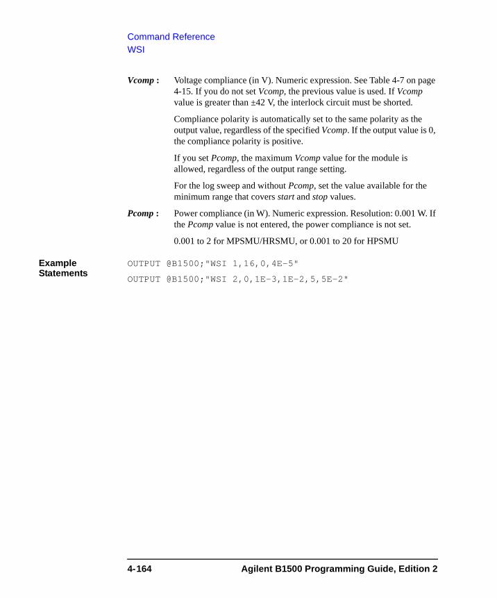
Command ReferenceWSI
Vcomp : Voltage compliance (in V). Numeric expression. See Table 4-7 on page 4-15. If you do not set Vcomp, the previous value is used. If Vcomp value is greater than ±42 V, the interlock circuit must be shorted.
Compliance polarity is automatically set to the same polarity as the output value, regardless of the specified Vcomp. If the output value is 0, the compliance polarity is positive.
If you set Pcomp, the maximum Vcomp value for the module is allowed, regardless of the output range setting.
For the log sweep and without Pcomp, set the value available for the minimum range that covers start and stop values.
Pcomp : Power compliance (in W). Numeric expression. Resolution: 0.001 W. If the Pcomp value is not entered, the power compliance is not set.
0.001 to 2 for MPSMU/HRSMU, or 0.001 to 20 for HPSMU
Example Statements
OUTPUT @B1500;"WSI 1,16,0,4E-5"
OUTPUT @B1500;"WSI 2,0,1E-3,1E-2,5,5E-2"
4-164 Agilent B1500 Programming Guide, Edition 2
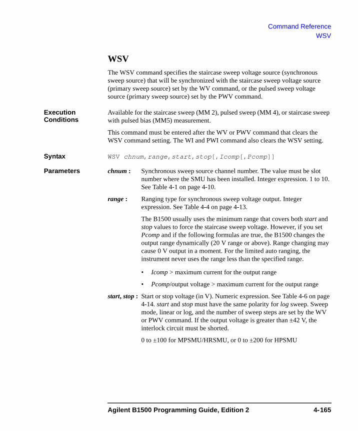
Command ReferenceWSV
WSV The WSV command specifies the staircase sweep voltage source (synchronous sweep source) that will be synchronized with the staircase sweep voltage source (primary sweep source) set by the WV command, or the pulsed sweep voltage source (primary sweep source) set by the PWV command.
Execution Conditions
Available for the staircase sweep (MM 2), pulsed sweep (MM 4), or staircase sweep with pulsed bias (MM5) measurement.
This command must be entered after the WV or PWV command that clears the WSV command setting. The WI and PWI command also clears the WSV setting.
Syntax WSV chnum,range,start,stop[,Icomp[,Pcomp]]
Parameters chnum : Synchronous sweep source channel number. The value must be slot number where the SMU has been installed. Integer expression. 1 to 10. See Table 4-1 on page 4-10.
range : Ranging type for synchronous sweep voltage output. Integer expression. See Table 4-4 on page 4-13.
The B1500 usually uses the minimum range that covers both start and stop values to force the staircase sweep voltage. However, if you set Pcomp and if the following formulas are true, the B1500 changes the output range dynamically (20 V range or above). Range changing may cause 0 V output in a moment. For the limited auto ranging, the instrument never uses the range less than the specified range.
• Icomp > maximum current for the output range
• Pcomp/output voltage > maximum current for the output range
start, stop : Start or stop voltage (in V). Numeric expression. See Table 4-6 on page 4-14. start and stop must have the same polarity for log sweep. Sweep mode, linear or log, and the number of sweep steps are set by the WV or PWV command. If the output voltage is greater than ±42 V, the interlock circuit must be shorted.
0 to ±100 for MPSMU/HRSMU, or 0 to ±200 for HPSMU
Agilent B1500 Programming Guide, Edition 2 4-165
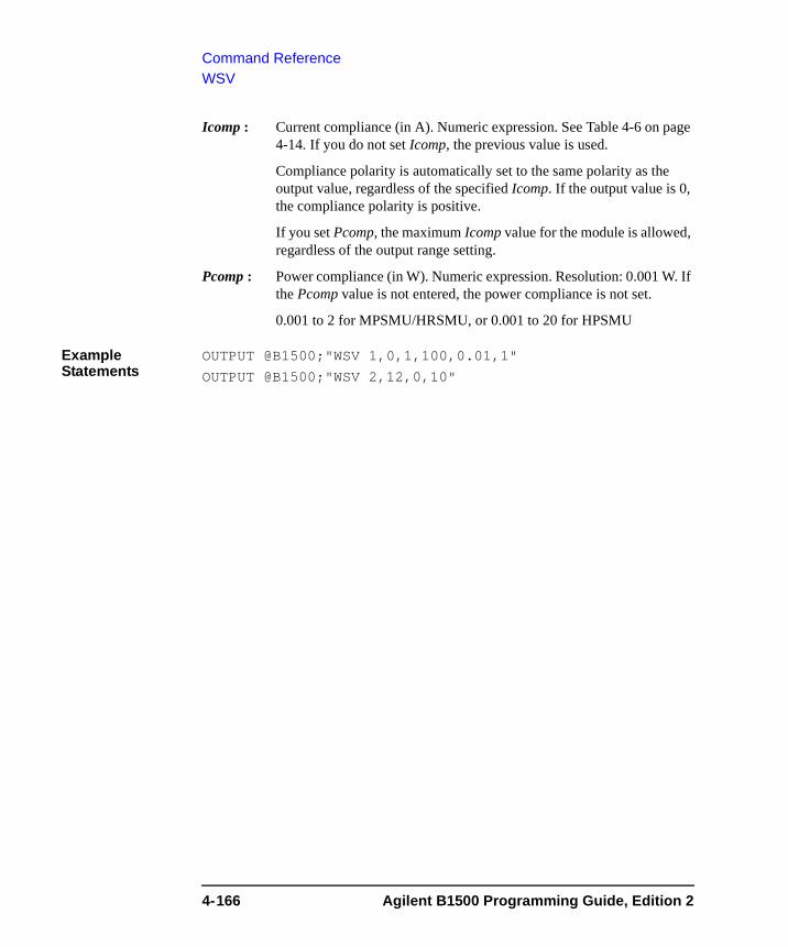
Command ReferenceWSV
Icomp : Current compliance (in A). Numeric expression. See Table 4-6 on page 4-14. If you do not set Icomp, the previous value is used.
Compliance polarity is automatically set to the same polarity as the output value, regardless of the specified Icomp. If the output value is 0, the compliance polarity is positive.
If you set Pcomp, the maximum Icomp value for the module is allowed, regardless of the output range setting.
Pcomp : Power compliance (in W). Numeric expression. Resolution: 0.001 W. If the Pcomp value is not entered, the power compliance is not set.
0.001 to 2 for MPSMU/HRSMU, or 0.001 to 20 for HPSMU
Example Statements
OUTPUT @B1500;"WSV 1,0,1,100,0.01,1"
OUTPUT @B1500;"WSV 2,12,0,10"
4-166 Agilent B1500 Programming Guide, Edition 2
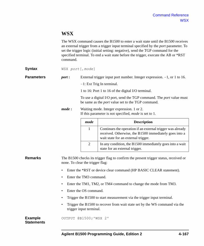
Command ReferenceWSX
WSXThe WSX command causes the B1500 to enter a wait state until the B1500 receives an external trigger from a trigger input terminal specified by the port parameter. To set the trigger logic (initial setting: negative), send the TGP command for the specified terminal. To end a wait state before the trigger, execute the AB or *RST command.
Syntax WSX port[,mode]
Parameters port : External trigger input port number. Integer expression. -1, or 1 to 16.
-1: Ext Trig In terminal.
1 to 16: Port 1 to 16 of the digital I/O terminal.
To use a digital I/O port, send the TGP command. The port value must be same as the port value set to the TGP command.
mode : Waiting mode. Integer expression. 1 or 2.If this parameter is not specified, mode is set to 1.
Remarks The B1500 checks its trigger flag to confirm the present trigger status, received or none. To clear the trigger flag:
• Enter the *RST or device clear command (HP BASIC CLEAR statement).
• Enter the TM3 command.
• Enter the TM1, TM2, or TM4 command to change the mode from TM3.
• Enter the OS command.
• Trigger the B1500 to start measurement via the trigger input terminal.
• Trigger the B1500 to recover from wait state set by the WS command via the trigger input terminal.
Example Statements
OUTPUT @B1500;"WSX 2"
mode Description
1 Continues the operation if an external trigger was already received. Otherwise, the B1500 immediately goes into a wait state for an external trigger.
2 In any condition, the B1500 immediately goes into a wait state for an external trigger.
Agilent B1500 Programming Guide, Edition 2 4-167
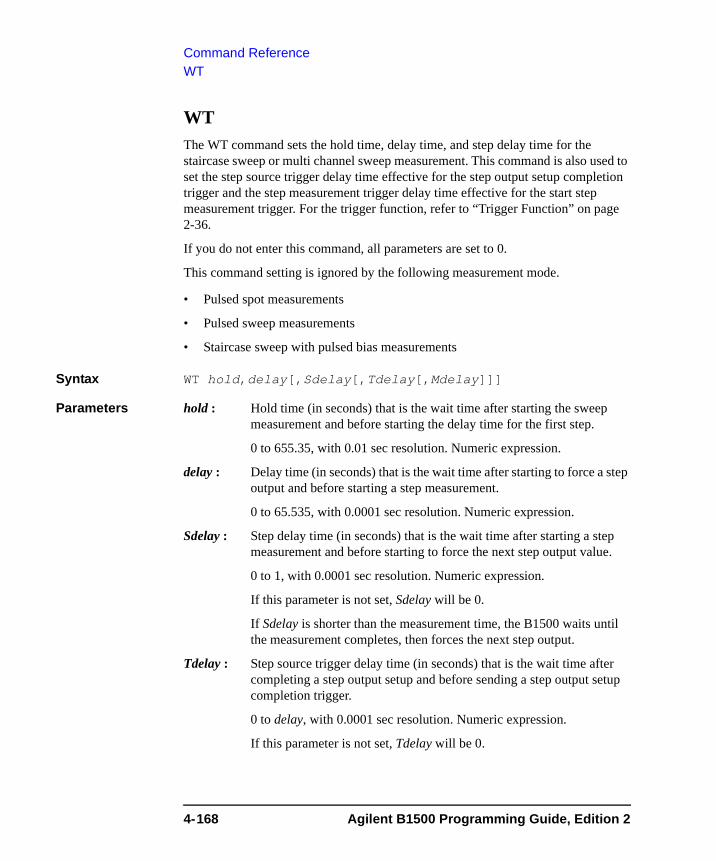
Command ReferenceWT
WT The WT command sets the hold time, delay time, and step delay time for the staircase sweep or multi channel sweep measurement. This command is also used to set the step source trigger delay time effective for the step output setup completion trigger and the step measurement trigger delay time effective for the start step measurement trigger. For the trigger function, refer to “Trigger Function” on page 2-36.
If you do not enter this command, all parameters are set to 0.
This command setting is ignored by the following measurement mode.
• Pulsed spot measurements
• Pulsed sweep measurements
• Staircase sweep with pulsed bias measurements
Syntax WT hold,delay[,Sdelay[,Tdelay[,Mdelay]]]
Parameters hold : Hold time (in seconds) that is the wait time after starting the sweep measurement and before starting the delay time for the first step.
0 to 655.35, with 0.01 sec resolution. Numeric expression.
delay : Delay time (in seconds) that is the wait time after starting to force a step output and before starting a step measurement.
0 to 65.535, with 0.0001 sec resolution. Numeric expression.
Sdelay : Step delay time (in seconds) that is the wait time after starting a step measurement and before starting to force the next step output value.
0 to 1, with 0.0001 sec resolution. Numeric expression.
If this parameter is not set, Sdelay will be 0.
If Sdelay is shorter than the measurement time, the B1500 waits until the measurement completes, then forces the next step output.
Tdelay : Step source trigger delay time (in seconds) that is the wait time after completing a step output setup and before sending a step output setup completion trigger.
0 to delay, with 0.0001 sec resolution. Numeric expression.
If this parameter is not set, Tdelay will be 0.
4-168 Agilent B1500 Programming Guide, Edition 2
Command ReferenceWT
Mdelay : Step measurement trigger delay time (in seconds) that is the wait time after receiving a start step measurement trigger and before starting a step measurement.
0 to 65.535, with 0.0001 sec resolution. Numeric expression.
If this parameter is not set, Mdelay will be 0.
Example Statements
OUTPUT @B1500;"WT 5,0.1,0.1,0.1,0.1"
OUTPUT @B1500;"WT 5,0.2"
Agilent B1500 Programming Guide, Edition 2 4-169
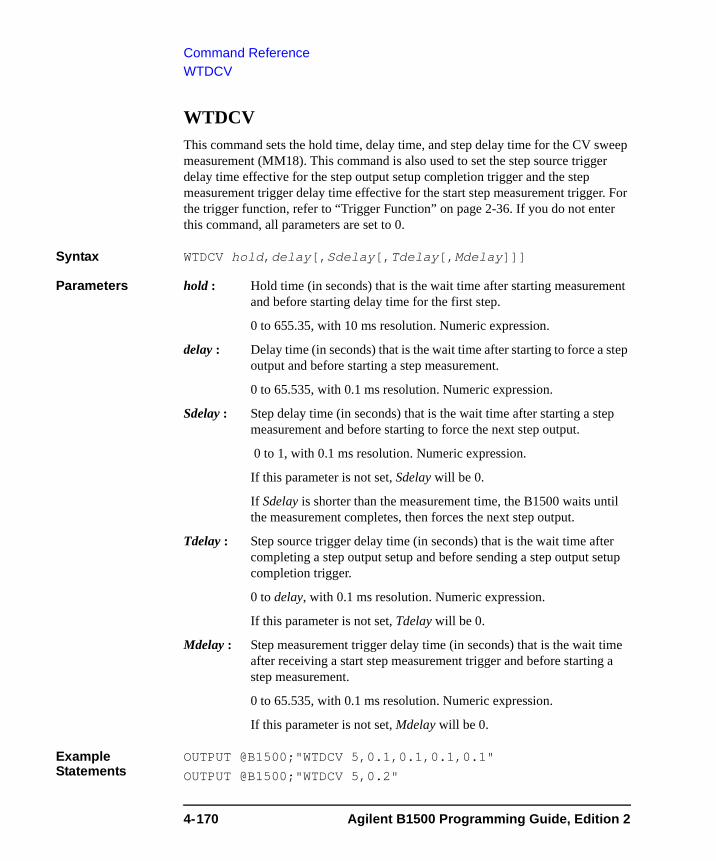
Command ReferenceWTDCV
WTDCVThis command sets the hold time, delay time, and step delay time for the CV sweep measurement (MM18). This command is also used to set the step source trigger delay time effective for the step output setup completion trigger and the step measurement trigger delay time effective for the start step measurement trigger. For the trigger function, refer to “Trigger Function” on page 2-36. If you do not enter this command, all parameters are set to 0.
Syntax WTDCV hold,delay[,Sdelay[,Tdelay[,Mdelay]]]
Parameters hold : Hold time (in seconds) that is the wait time after starting measurement and before starting delay time for the first step.
0 to 655.35, with 10 ms resolution. Numeric expression.
delay : Delay time (in seconds) that is the wait time after starting to force a step output and before starting a step measurement.
0 to 65.535, with 0.1 ms resolution. Numeric expression.
Sdelay : Step delay time (in seconds) that is the wait time after starting a step measurement and before starting to force the next step output.
0 to 1, with 0.1 ms resolution. Numeric expression.
If this parameter is not set, Sdelay will be 0.
If Sdelay is shorter than the measurement time, the B1500 waits until the measurement completes, then forces the next step output.
Tdelay : Step source trigger delay time (in seconds) that is the wait time after completing a step output setup and before sending a step output setup completion trigger.
0 to delay, with 0.1 ms resolution. Numeric expression.
If this parameter is not set, Tdelay will be 0.
Mdelay : Step measurement trigger delay time (in seconds) that is the wait time after receiving a start step measurement trigger and before starting a step measurement.
0 to 65.535, with 0.1 ms resolution. Numeric expression.
If this parameter is not set, Mdelay will be 0.
Example Statements
OUTPUT @B1500;"WTDCV 5,0.1,0.1,0.1,0.1"
OUTPUT @B1500;"WTDCV 5,0.2"
4-170 Agilent B1500 Programming Guide, Edition 2
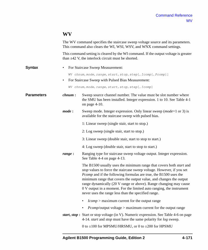
Command ReferenceWV
WV The WV command specifies the staircase sweep voltage source and its parameters. This command also clears the WI, WSI, WSV, and WNX command settings.
This command setting is cleared by the WI command. If the output voltage is greater than ±42 V, the interlock circuit must be shorted.
Syntax • For Staircase Sweep Measurement:
WV chnum,mode,range,start,stop,step[,Icomp[,Pcomp]]
• For Staircase Sweep with Pulsed Bias Measurement:
WV chnum,mode,range,start,stop,step[,Icomp]
Parameters chnum : Sweep source channel number. The value must be slot number where the SMU has been installed. Integer expression. 1 to 10. See Table 4-1 on page 4-10.
mode : Sweep mode. Integer expression. Only linear sweep (mode=1 or 3) is available for the staircase sweep with pulsed bias.
1: Linear sweep (single stair, start to stop.)
2: Log sweep (single stair, start to stop.)
3: Linear sweep (double stair, start to stop to start.)
4: Log sweep (double stair, start to stop to start.)
range : Ranging type for staircase sweep voltage output. Integer expression. See Table 4-4 on page 4-13.
The B1500 usually uses the minimum range that covers both start and stop values to force the staircase sweep voltage. However, if you set Pcomp and if the following formulas are true, the B1500 uses the minimum range that covers the output value, and changes the output range dynamically (20 V range or above). Range changing may cause 0 V output in a moment. For the limited auto ranging, the instrument never uses the range less than the specified range.
• Icomp > maximum current for the output range
• Pcomp/output voltage > maximum current for the output range
start, stop : Start or stop voltage (in V). Numeric expression. See Table 4-6 on page 4-14. start and stop must have the same polarity for log sweep.
0 to ±100 for MPSMU/HRSMU, or 0 to ±200 for HPSMU
Agilent B1500 Programming Guide, Edition 2 4-171
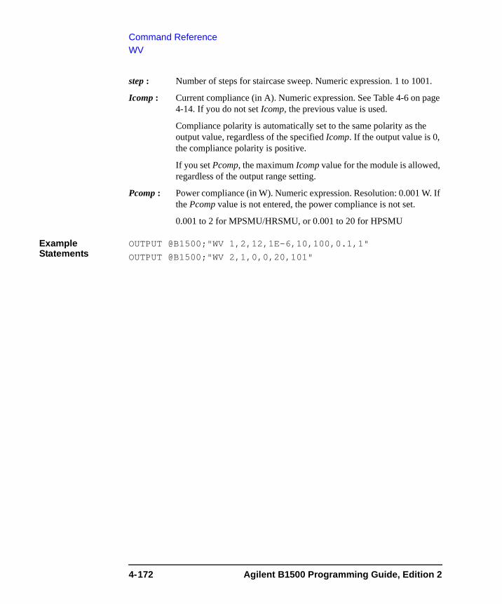
Command ReferenceWV
step : Number of steps for staircase sweep. Numeric expression. 1 to 1001.
Icomp : Current compliance (in A). Numeric expression. See Table 4-6 on page 4-14. If you do not set Icomp, the previous value is used.
Compliance polarity is automatically set to the same polarity as the output value, regardless of the specified Icomp. If the output value is 0, the compliance polarity is positive.
If you set Pcomp, the maximum Icomp value for the module is allowed, regardless of the output range setting.
Pcomp : Power compliance (in W). Numeric expression. Resolution: 0.001 W. If the Pcomp value is not entered, the power compliance is not set.
0.001 to 2 for MPSMU/HRSMU, or 0.001 to 20 for HPSMU
Example Statements
OUTPUT @B1500;"WV 1,2,12,1E-6,10,100,0.1,1"
OUTPUT @B1500;"WV 2,1,0,0,20,101"
4-172 Agilent B1500 Programming Guide, Edition 2
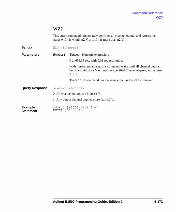
Command ReferenceWZ?
WZ?This query command immediately confirms all channel output, and returns the status 0 if it is within ±2 V or 1 if it is more than ±2 V.
Syntax WZ? [timeout]
Parameters timeout : Timeout. Numeric expression.
0 to 655.35 sec, with 0.01 sec resolution.
With timeout parameter, this command waits until all channel output becomes within ±2 V or until the specified timeout elapses, and returns 0 or 1.
The WZ? 0 command has the same effect as the WZ? command.
Query Response state<CR/LF^EOI>
0: All channel output is within ±2 V.
1: Any output channel applies more than ±2 V.
Example Statement
OUTPUT @B1500;"WZ? 5.0" ENTER @B1500;A
Agilent B1500 Programming Guide, Edition 2 4-173
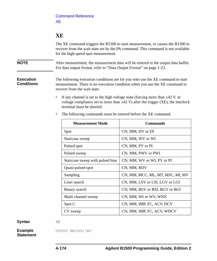
Command ReferenceXE
XE The XE command triggers the B1500 to start measurement, or causes the B1500 to recover from the wait state set by the PA command. This command is not available for the high-speed spot measurement.
NOTE After measurement, the measurement data will be entered to the output data buffer. For data output format, refer to “Data Output Format” on page 1-23.
Execution Conditions
The following execution conditions are for you who use the XE command to start measurement. There is no execution condition when you use the XE command to recover from the wait state.
• If any channel is set to the high voltage state (forcing more than ±42 V, or voltage compliance set to more than ±42 V) after the trigger (XE), the interlock terminal must be shorted.
• The following commands must be entered before the XE command.
Syntax XE
Example Statement
OUTPUT @B1500;"XE"
Measurement Mode Commands
Spot CN, MM, DV or DI
Staircase sweep CN, MM, WV or WI
Pulsed spot CN, MM, PV or PI
Pulsed sweep CN, MM, PWV or PWI
Staircase sweep with pulsed bias CN, MM, WV or WI, PV or PI
Quasi-pulsed spot CN, MM, BDV
Sampling CN, MM, MCC, ML, MT, MSC, MI, MV
Liner search CN, MM, LSV or LSI, LGV or LGI
Binary search CN, MM, BSV or BSI, BGV or BGI
Multi channel sweep CN, MM, WI or WV, WNX
Spot C CN, MM, IMP, FC, ACV, DCV
CV sweep CN, MM, IMP, FC, ACV, WDCV
4-174 Agilent B1500 Programming Guide, Edition 2

5 Error Messages
Error Messages
This chapter explains the error code of the Agilent B1500.
• “Error Codes”
If error occurs, find solutions in this section and solve problems. However, if problems still remain, perform self-test.
If the Agilent B1500 fails self-test, contact your nearest Agilent Technologies Service Center.
5-2 Agilent B1500 Programming Guide, Edition 2

Error MessagesError Codes
Error CodesIf errors occur, error codes are stored in the error buffer. To read the error code, execute the “ERR?” command. To read the error message, execute the “EMG?” command.
The output of the error codes is in the order that they occurred, and the first four error codes are stored in the buffer. If no errors occurred, ”0, 0, 0, 0” is returned.
Operation Error100 Undefined GPIB command.
Send the correct command.
102 Incorrect numeric data syntax.
Correct the data syntax.
103 Incorrect terminator position.
Correct the command syntax. The number of parameters will be incorrect.
104 Incorrect serial data syntax.
120 Incorrect parameter value.
Correct the parameter value.
121 Channel number must be 1 to 10.
Correct the channel number. The channel number must be 1 to 10 for the Agilent B1500.
122 Number of channels must be corrected.
Check the MM, FL, CN, CL, IN, DZ, or RZ command, and correct the number of channels.
123 Compliance must be set correctly.
Incorrect compliance value was set. Set the compliance value correctly.
124 Incorrect range value for this channel.
Check the range value available for the channel, and correct the range value.
Agilent B1500 Programming Guide, Edition 2 5-3

Error MessagesError Codes
125 Search goal value must be less than compliance value.
126 Pulse base and peak must be same polarity.
The polarity of the base and peak values must be the same in the PI command. Also the polarity of the base, start, and stop values must be the same in the PWI command.
130 Start and stop must be same polarity.
For a log sweep, the polarity of the start and stop values must be the same in the WV, WI, WSV, WSI, or WNX command. Also, 0 is not allowed for the start and stop values.
150 Command input buffer is full.
The Agilent B1500 can receive 256 characters maximum including the terminator at one time.
151 This command is not allowed to this channel.
152 Cannot use failed module.
The channel number specifying the module failed the self-test or calibration. Specify another module that passed the self-test or calibration. For the service purpose, execute the RCV command to enable the module.
153 No module for the specified channel.
Module is not installed in the slot specified by the channel number.
160 Incorrect ST execution.
The internal memory programming can be started by the ST command and completed by the END command. Do not enter the ST command between the ST command and the END command.
161 Incorrect END execution.
The internal memory programming can be started by the ST command and completed by the END command. Do not send the END command before starting the programming.
162 Incorrect command for program memory.
Specified command cannot be stored in the program memory. For the incorrect commands, refer to Table 2-1 on page 2-32.
5-4 Agilent B1500 Programming Guide, Edition 2
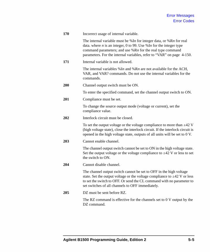
Error MessagesError Codes
170 Incorrect usage of internal variable.
The internal variable must be %In for integer data, or %Rn for real data. where n is an integer, 0 to 99. Use %In for the integer type command parameters; and use %Rn for the real type command parameters. For the internal variables, refer to “VAR” on page 4-150.
171 Internal variable is not allowed.
The internal variables %In and %Rn are not available for the ACH, VAR, and VAR? commands. Do not use the internal variables for the commands.
200 Channel output switch must be ON.
To enter the specified command, set the channel output switch to ON.
201 Compliance must be set.
To change the source output mode (voltage or current), set the compliance value.
202 Interlock circuit must be closed.
To set the output voltage or the voltage compliance to more than ±42 V (high voltage state), close the interlock circuit. If the interlock circuit is opened in the high voltage state, outputs of all units will be set to 0 V.
203 Cannot enable channel.
The channel output switch cannot be set to ON in the high voltage state. Set the output voltage or the voltage compliance to ±42 V or less to set the switch to ON.
204 Cannot disable channel.
The channel output switch cannot be set to OFF in the high voltage state. Set the output voltage or the voltage compliance to ±42 V or less to set the switch to OFF. Or send the CL command with no parameter to set switches of all channels to OFF immediately.
205 DZ must be sent before RZ.
The RZ command is effective for the channels set to 0 V output by the DZ command.
Agilent B1500 Programming Guide, Edition 2 5-5
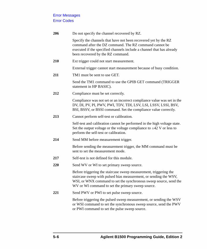
Error MessagesError Codes
206 Do not specify the channel recovered by RZ.
Specify the channels that have not been recovered yet by the RZ command after the DZ command. The RZ command cannot be executed if the specified channels include a channel that has already been recovered by the RZ command.
210 Ext trigger could not start measurement.
External trigger cannot start measurement because of busy condition.
211 TM1 must be sent to use GET.
Send the TM1 command to use the GPIB GET command (TRIGGER statement in HP BASIC).
212 Compliance must be set correctly.
Compliance was not set or an incorrect compliance value was set in the DV, DI, PV, PI, PWV, PWI, TDV, TDI, LSV, LSI, LSSV, LSSI, BSV, BSI, BSSV, or BSSI command. Set the compliance value correctly.
213 Cannot perform self-test or calibration.
Self-test and calibration cannot be performed in the high voltage state. Set the output voltage or the voltage compliance to ±42 V or less to perform the self-test or calibration.
214 Send MM before measurement trigger.
Before sending the measurement trigger, the MM command must be sent to set the measurement mode.
217 Self-test is not defined for this module.
220 Send WV or WI to set primary sweep source.
Before triggering the staircase sweep measurement, triggering the staircase sweep with pulsed bias measurement, or sending the WSV, WSI, or WNX command to set the synchronous sweep source, send the WV or WI command to set the primary sweep source.
221 Send PWV or PWI to set pulse sweep source.
Before triggering the pulsed sweep measurement, or sending the WSV or WSI command to set the synchronous sweep source, send the PWV or PWI command to set the pulse sweep source.
5-6 Agilent B1500 Programming Guide, Edition 2
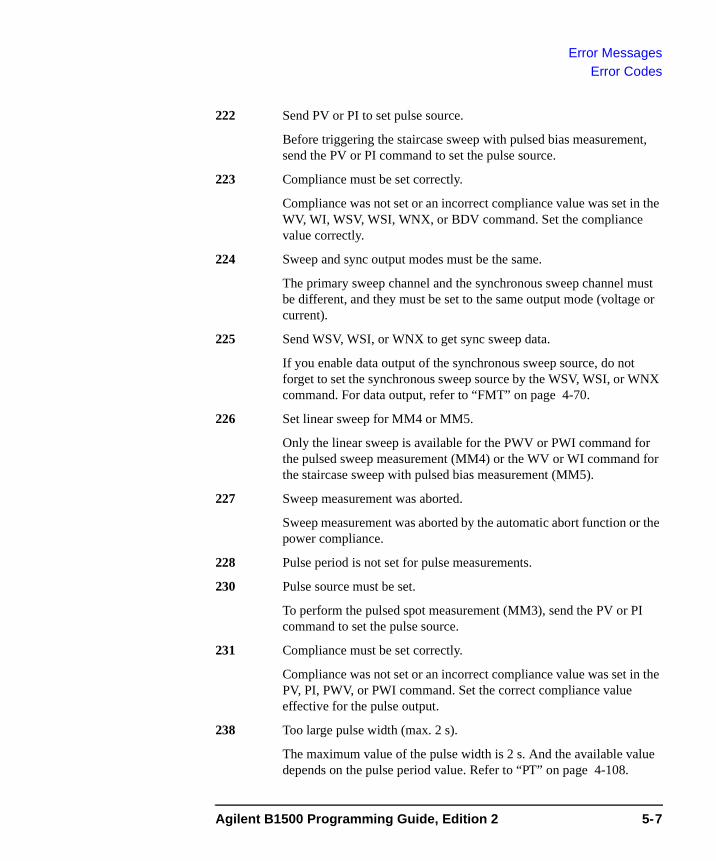
Error MessagesError Codes
222 Send PV or PI to set pulse source.
Before triggering the staircase sweep with pulsed bias measurement, send the PV or PI command to set the pulse source.
223 Compliance must be set correctly.
Compliance was not set or an incorrect compliance value was set in the WV, WI, WSV, WSI, WNX, or BDV command. Set the compliance value correctly.
224 Sweep and sync output modes must be the same.
The primary sweep channel and the synchronous sweep channel must be different, and they must be set to the same output mode (voltage or current).
225 Send WSV, WSI, or WNX to get sync sweep data.
If you enable data output of the synchronous sweep source, do not forget to set the synchronous sweep source by the WSV, WSI, or WNX command. For data output, refer to “FMT” on page 4-70.
226 Set linear sweep for MM4 or MM5.
Only the linear sweep is available for the PWV or PWI command for the pulsed sweep measurement (MM4) or the WV or WI command for the staircase sweep with pulsed bias measurement (MM5).
227 Sweep measurement was aborted.
Sweep measurement was aborted by the automatic abort function or the power compliance.
228 Pulse period is not set for pulse measurements.
230 Pulse source must be set.
To perform the pulsed spot measurement (MM3), send the PV or PI command to set the pulse source.
231 Compliance must be set correctly.
Compliance was not set or an incorrect compliance value was set in the PV, PI, PWV, or PWI command. Set the correct compliance value effective for the pulse output.
238 Too large pulse width (max. 2 s).
The maximum value of the pulse width is 2 s. And the available value depends on the pulse period value. Refer to “PT” on page 4-108.
Agilent B1500 Programming Guide, Edition 2 5-7
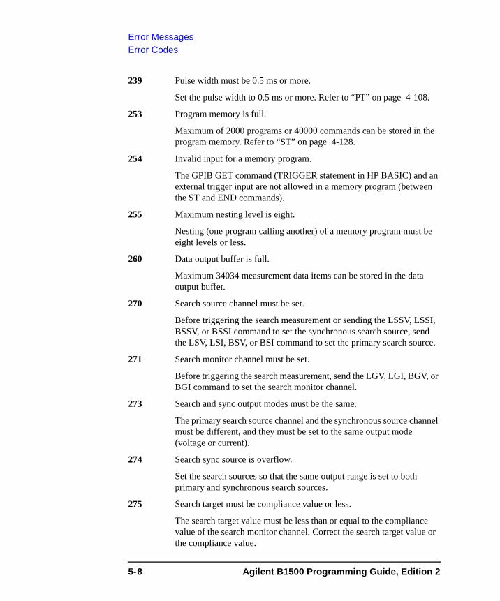
Error MessagesError Codes
239 Pulse width must be 0.5 ms or more.
Set the pulse width to 0.5 ms or more. Refer to “PT” on page 4-108.
253 Program memory is full.
Maximum of 2000 programs or 40000 commands can be stored in the program memory. Refer to “ST” on page 4-128.
254 Invalid input for a memory program.
The GPIB GET command (TRIGGER statement in HP BASIC) and an external trigger input are not allowed in a memory program (between the ST and END commands).
255 Maximum nesting level is eight.
Nesting (one program calling another) of a memory program must be eight levels or less.
260 Data output buffer is full.
Maximum 34034 measurement data items can be stored in the data output buffer.
270 Search source channel must be set.
Before triggering the search measurement or sending the LSSV, LSSI, BSSV, or BSSI command to set the synchronous search source, send the LSV, LSI, BSV, or BSI command to set the primary search source.
271 Search monitor channel must be set.
Before triggering the search measurement, send the LGV, LGI, BGV, or BGI command to set the search monitor channel.
273 Search and sync output modes must be the same.
The primary search source channel and the synchronous source channel must be different, and they must be set to the same output mode (voltage or current).
274 Search sync source is overflow.
Set the search sources so that the same output range is set to both primary and synchronous search sources.
275 Search target must be compliance value or less.
The search target value must be less than or equal to the compliance value of the search monitor channel. Correct the search target value or the compliance value.
5-8 Agilent B1500 Programming Guide, Edition 2
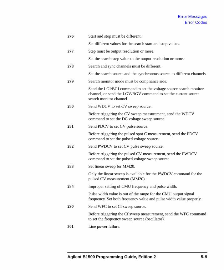
Error MessagesError Codes
276 Start and stop must be different.
Set different values for the search start and stop values.
277 Step must be output resolution or more.
Set the search step value to the output resolution or more.
278 Search and sync channels must be different.
Set the search source and the synchronous source to different channels.
279 Search monitor mode must be compliance side.
Send the LGI/BGI command to set the voltage source search monitor channel, or send the LGV/BGV command to set the current source search monitor channel.
280 Send WDCV to set CV sweep source.
Before triggering the CV sweep measurement, send the WDCV command to set the DC voltage sweep source.
281 Send PDCV to set CV pulse source.
Before triggering the pulsed spot C measurement, send the PDCV command to set the pulsed voltage source.
282 Send PWDCV to set CV pulse sweep source.
Before triggering the pulsed CV measurement, send the PWDCV command to set the pulsed voltage sweep source.
283 Set linear sweep for MM20.
Only the linear sweep is available for the PWDCV command for the pulsed CV measurement (MM20).
284 Improper setting of CMU frequency and pulse width.
Pulse width value is out of the range for the CMU output signal frequency. Set both frequency value and pulse width value properly.
290 Send WFC to set Cf sweep source.
Before triggering the Cf sweep measurement, send the WFC command to set the frequency sweep source (oscillator).
301 Line power failure.
Agilent B1500 Programming Guide, Edition 2 5-9
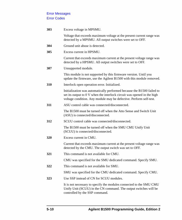
Error MessagesError Codes
303 Excess voltage in MPSMU.
Voltage that exceeds maximum voltage at the present current range was detected by a MPSMU. All output switches were set to OFF.
304 Ground unit abuse is detected.
305 Excess current in HPSMU.
Current that exceeds maximum current at the present voltage range was detected by a HPSMU. All output switches were set to OFF.
307 Unsupported module.
This module is not supported by this firmware version. Until you update the firmware, use the Agilent B1500 with this module removed.
310 Interlock open operation error. Initialized.
Initialization was automatically performed because the B1500 failed to set its output to 0 V when the interlock circuit was opened in the high voltage condition. Any module may be defective. Perform self-test.
311 ASU control cable was connected/disconnected.
The B1500 must be turned off when the Atto Sense and Switch Unit (ASU) is connected/disconnected.
312 SCUU control cable was connected/disconnected.
The B1500 must be turned off when the SMU CMU Unify Unit (SCUU) is connected/disconnected.
320 Excess current in CMU.
Current that exceeds maximum current at the present voltage range was detected by the CMU. The output switch was set to OFF.
321 This command is not available for CMU.
CMU was specified for the SMU dedicated command. Specify SMU.
322 This command is not available for SMU.
SMU was specified for the CMU dedicated command. Specify CMU.
323 Use SSP instead of CN for SCUU modules.
It is not necessary to specify the modules connected to the SMU CMU Unify Unit (SCUU) in the CN command. The output switches will be controlled by the SSP command.
5-10 Agilent B1500 Programming Guide, Edition 2
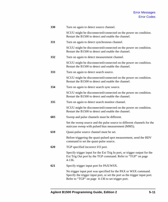
Error MessagesError Codes
330 Turn on again to detect source channel.
SCUU might be disconnected/connected on the power on condition. Restart the B1500 to detect and enable the channel.
331 Turn on again to detect synchronous channel.
SCUU might be disconnected/connected on the power on condition. Restart the B1500 to detect and enable the channel.
332 Turn on again to detect measurement channel.
SCUU might be disconnected/connected on the power on condition. Restart the B1500 to detect and enable the channel.
333 Turn on again to detect search source.
SCUU might be disconnected/connected on the power on condition. Restart the B1500 to detect and enable the channel.
334 Turn on again to detect search sync source.
SCUU might be disconnected/connected on the power on condition. Restart the B1500 to detect and enable the channel.
335 Turn on again to detect search monitor channel.
SCUU might be disconnected/connected on the power on condition. Restart the B1500 to detect and enable the channel.
603 Sweep and pulse channels must be different.
Set the sweep source and the pulse source to different channels for the staircase sweep with pulsed bias measurement (MM5).
610 Quasi-pulse source channel must be set.
Before triggering the quasi-pulsed spot measurement, send the BDV command to set the quasi-pulse source.
620 TGP specified incorrect I/O port.
Specify trigger input for the Ext Trig In port, or trigger output for the Ext Trig Out port by the TGP command. Refer to “TGP” on page 4-136.
621 Specify trigger input port for PAX/WSX.
No trigger input port was specified for the PAX or WSX command. Specify the trigger input port, or set the port as the trigger input port. Refer to “TGP” on page 4-136 to set trigger port.
Agilent B1500 Programming Guide, Edition 2 5-11
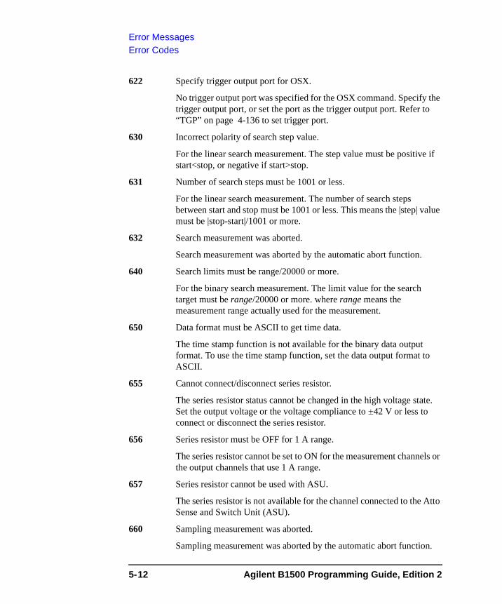
Error MessagesError Codes
622 Specify trigger output port for OSX.
No trigger output port was specified for the OSX command. Specify the trigger output port, or set the port as the trigger output port. Refer to “TGP” on page 4-136 to set trigger port.
630 Incorrect polarity of search step value.
For the linear search measurement. The step value must be positive if start<stop, or negative if start>stop.
631 Number of search steps must be 1001 or less.
For the linear search measurement. The number of search steps between start and stop must be 1001 or less. This means the |step| value must be |stop-start|/1001 or more.
632 Search measurement was aborted.
Search measurement was aborted by the automatic abort function.
640 Search limits must be range/20000 or more.
For the binary search measurement. The limit value for the search target must be range/20000 or more. where range means the measurement range actually used for the measurement.
650 Data format must be ASCII to get time data.
The time stamp function is not available for the binary data output format. To use the time stamp function, set the data output format to ASCII.
655 Cannot connect/disconnect series resistor.
The series resistor status cannot be changed in the high voltage state. Set the output voltage or the voltage compliance to ±42 V or less to connect or disconnect the series resistor.
656 Series resistor must be OFF for 1 A range.
The series resistor cannot be set to ON for the measurement channels or the output channels that use 1 A range.
657 Series resistor cannot be used with ASU.
The series resistor is not available for the channel connected to the Atto Sense and Switch Unit (ASU).
660 Sampling measurement was aborted.
Sampling measurement was aborted by the automatic abort function.
5-12 Agilent B1500 Programming Guide, Edition 2
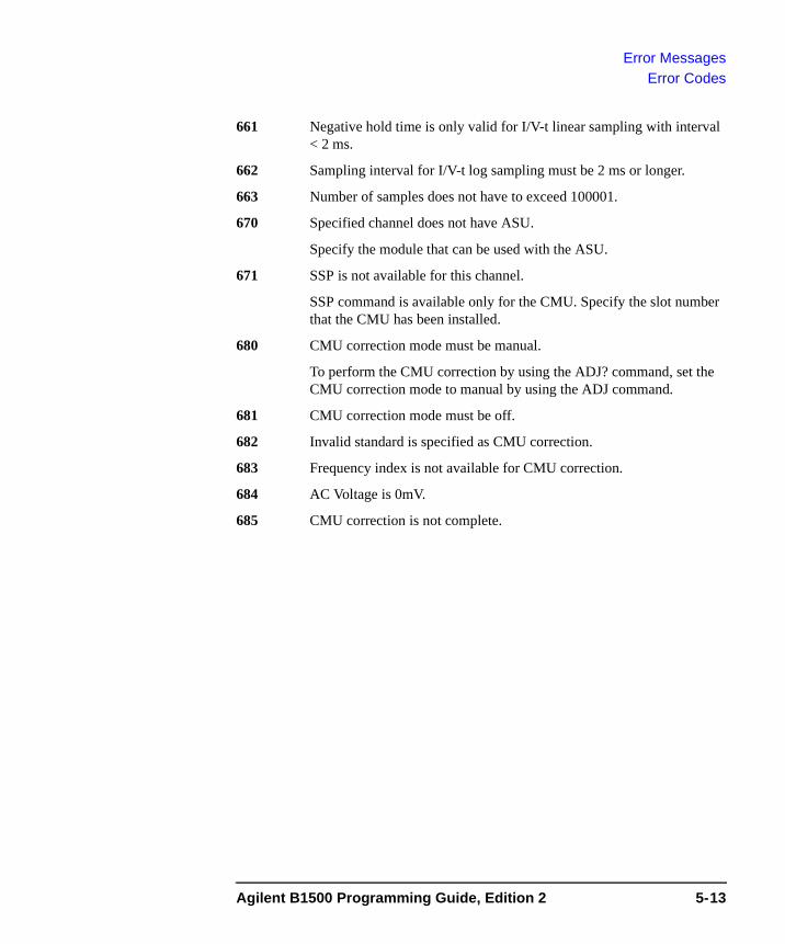
Error MessagesError Codes
661 Negative hold time is only valid for I/V-t linear sampling with interval < 2 ms.
662 Sampling interval for I/V-t log sampling must be 2 ms or longer.
663 Number of samples does not have to exceed 100001.
670 Specified channel does not have ASU.
Specify the module that can be used with the ASU.
671 SSP is not available for this channel.
SSP command is available only for the CMU. Specify the slot number that the CMU has been installed.
680 CMU correction mode must be manual.
To perform the CMU correction by using the ADJ? command, set the CMU correction mode to manual by using the ADJ command.
681 CMU correction mode must be off.
682 Invalid standard is specified as CMU correction.
683 Frequency index is not available for CMU correction.
684 AC Voltage is 0mV.
685 CMU correction is not complete.
Agilent B1500 Programming Guide, Edition 2 5-13
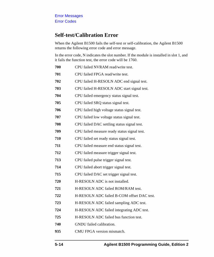
Error MessagesError Codes
Self-test/Calibration ErrorWhen the Agilent B1500 fails the self-test or self-calibration, the Agilent B1500 returns the following error code and error message.
In the error code, N indicates the slot number. If the module is installed in slot 1, and it fails the function test, the error code will be 1760.
700 CPU failed NVRAM read/write test.
701 CPU failed FPGA read/write test.
702 CPU failed H-RESOLN ADC end signal test.
703 CPU failed H-RESOLN ADC start signal test.
704 CPU failed emergency status signal test.
705 CPU failed SRQ status signal test.
706 CPU failed high voltage status signal test.
707 CPU failed low voltage status signal test.
708 CPU failed DAC settling status signal test.
709 CPU failed measure ready status signal test.
710 CPU failed set ready status signal test.
711 CPU failed measure end status signal test.
712 CPU failed measure trigger signal test.
713 CPU failed pulse trigger signal test.
714 CPU failed abort trigger signal test.
715 CPU failed DAC set trigger signal test.
720 H-RESOLN ADC is not installed.
721 H-RESOLN ADC failed ROM/RAM test.
722 H-RESOLN ADC failed B-COM offset DAC test.
723 H-RESOLN ADC failed sampling ADC test.
724 H-RESOLN ADC failed integrating ADC test.
725 H-RESOLN ADC failed bus function test.
740 GNDU failed calibration.
935 CMU FPGA version mismatch.
5-14 Agilent B1500 Programming Guide, Edition 2
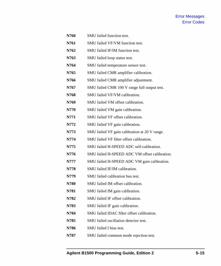
Error MessagesError Codes
N760 SMU failed function test.
N761 SMU failed VF/VM function test.
N762 SMU failed IF/IM function test.
N763 SMU failed loop status test.
N764 SMU failed temperature sensor test.
N765 SMU failed CMR amplifier calibration.
N766 SMU failed CMR amplifier adjustment.
N767 SMU failed CMR 100 V range full output test.
N768 SMU failed VF/VM calibration.
N769 SMU failed VM offset calibration.
N770 SMU failed VM gain calibration.
N771 SMU failed VF offset calibration.
N772 SMU failed VF gain calibration.
N773 SMU failed VF gain calibration at 20 V range.
N774 SMU failed VF filter offset calibration.
N775 SMU failed H-SPEED ADC self-calibration.
N776 SMU failed H-SPEED ADC VM offset calibration.
N777 SMU failed H-SPEED ADC VM gain calibration.
N778 SMU failed IF/IM calibration.
N779 SMU failed calibration bus test.
N780 SMU failed IM offset calibration.
N781 SMU failed IM gain calibration.
N782 SMU failed IF offset calibration.
N783 SMU failed IF gain calibration.
N784 SMU failed IDAC filter offset calibration.
N785 SMU failed oscillation detector test.
N786 SMU failed I bias test.
N787 SMU failed common mode rejection test.
Agilent B1500 Programming Guide, Edition 2 5-15
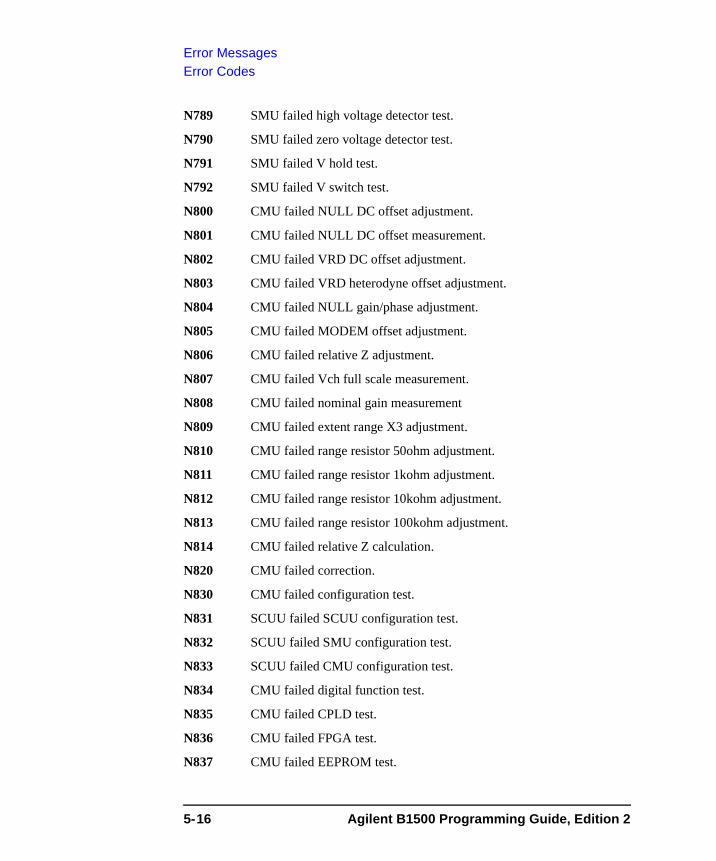
Error MessagesError Codes
N789 SMU failed high voltage detector test.
N790 SMU failed zero voltage detector test.
N791 SMU failed V hold test.
N792 SMU failed V switch test.
N800 CMU failed NULL DC offset adjustment.
N801 CMU failed NULL DC offset measurement.
N802 CMU failed VRD DC offset adjustment.
N803 CMU failed VRD heterodyne offset adjustment.
N804 CMU failed NULL gain/phase adjustment.
N805 CMU failed MODEM offset adjustment.
N806 CMU failed relative Z adjustment.
N807 CMU failed Vch full scale measurement.
N808 CMU failed nominal gain measurement
N809 CMU failed extent range X3 adjustment.
N810 CMU failed range resistor 50ohm adjustment.
N811 CMU failed range resistor 1kohm adjustment.
N812 CMU failed range resistor 10kohm adjustment.
N813 CMU failed range resistor 100kohm adjustment.
N814 CMU failed relative Z calculation.
N820 CMU failed correction.
N830 CMU failed configuration test.
N831 SCUU failed SCUU configuration test.
N832 SCUU failed SMU configuration test.
N833 SCUU failed CMU configuration test.
N834 CMU failed digital function test.
N835 CMU failed CPLD test.
N836 CMU failed FPGA test.
N837 CMU failed EEPROM test.
5-16 Agilent B1500 Programming Guide, Edition 2
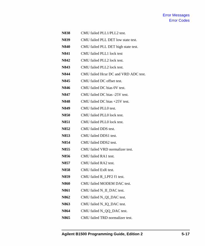
Error MessagesError Codes
N838 CMU failed PLL1/PLL2 test.
N839 CMU failed PLL DET low state test.
N840 CMU failed PLL DET high state test.
N841 CMU failed PLL1 lock test
N842 CMU failed PLL2 lock test.
N843 CMU failed PLL2 lock test.
N844 CMU failed Hcur DC and VRD ADC test.
N845 CMU failed DC offset test.
N846 CMU failed DC bias 0V test.
N847 CMU failed DC bias -25V test.
N848 CMU failed DC bias +25V test.
N849 CMU failed PLL0 test.
N850 CMU failed PLL0 lock test.
N851 CMU failed PLL0 lock test.
N852 CMU failed DDS test.
N853 CMU failed DDS1 test.
N854 CMU failed DDS2 test.
N855 CMU failed VRD normalizer test.
N856 CMU failed RA1 test.
N857 CMU failed RA2 test.
N858 CMU failed ExR test.
N859 CMU failed R_LPF2 f1 test.
N860 CMU failed MODEM DAC test.
N861 CMU failed N_II_DAC test.
N862 CMU failed N_QI_DAC test.
N863 CMU failed N_IQ_DAC test.
N864 CMU failed N_QQ_DAC test.
N865 CMU failed TRD normalizer test.
Agilent B1500 Programming Guide, Edition 2 5-17
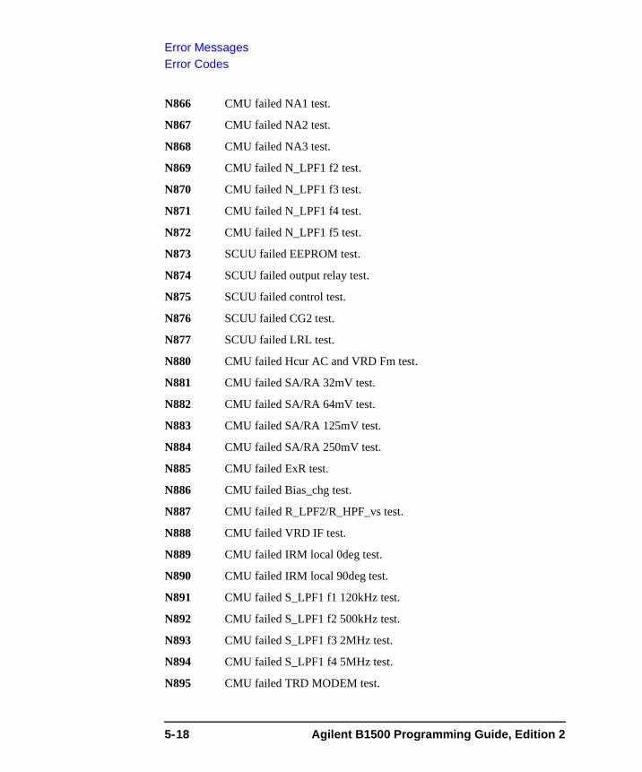
Error MessagesError Codes
N866 CMU failed NA1 test.
N867 CMU failed NA2 test.
N868 CMU failed NA3 test.
N869 CMU failed N_LPF1 f2 test.
N870 CMU failed N_LPF1 f3 test.
N871 CMU failed N_LPF1 f4 test.
N872 CMU failed N_LPF1 f5 test.
N873 SCUU failed EEPROM test.
N874 SCUU failed output relay test.
N875 SCUU failed control test.
N876 SCUU failed CG2 test.
N877 SCUU failed LRL test.
N880 CMU failed Hcur AC and VRD Fm test.
N881 CMU failed SA/RA 32mV test.
N882 CMU failed SA/RA 64mV test.
N883 CMU failed SA/RA 125mV test.
N884 CMU failed SA/RA 250mV test.
N885 CMU failed ExR test.
N886 CMU failed Bias_chg test.
N887 CMU failed R_LPF2/R_HPF_vs test.
N888 CMU failed VRD IF test.
N889 CMU failed IRM local 0deg test.
N890 CMU failed IRM local 90deg test.
N891 CMU failed S_LPF1 f1 120kHz test.
N892 CMU failed S_LPF1 f2 500kHz test.
N893 CMU failed S_LPF1 f3 2MHz test.
N894 CMU failed S_LPF1 f4 5MHz test.
N895 CMU failed TRD MODEM test.
5-18 Agilent B1500 Programming Guide, Edition 2
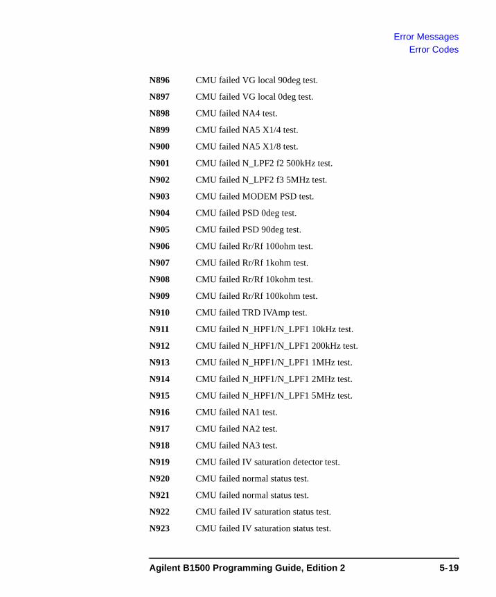
Error MessagesError Codes
N896 CMU failed VG local 90deg test.
N897 CMU failed VG local 0deg test.
N898 CMU failed NA4 test.
N899 CMU failed NA5 X1/4 test.
N900 CMU failed NA5 X1/8 test.
N901 CMU failed N_LPF2 f2 500kHz test.
N902 CMU failed N_LPF2 f3 5MHz test.
N903 CMU failed MODEM PSD test.
N904 CMU failed PSD 0deg test.
N905 CMU failed PSD 90deg test.
N906 CMU failed Rr/Rf 100ohm test.
N907 CMU failed Rr/Rf 1kohm test.
N908 CMU failed Rr/Rf 10kohm test.
N909 CMU failed Rr/Rf 100kohm test.
N910 CMU failed TRD IVAmp test.
N911 CMU failed N_HPF1/N_LPF1 10kHz test.
N912 CMU failed N_HPF1/N_LPF1 200kHz test.
N913 CMU failed N_HPF1/N_LPF1 1MHz test.
N914 CMU failed N_HPF1/N_LPF1 2MHz test.
N915 CMU failed N_HPF1/N_LPF1 5MHz test.
N916 CMU failed NA1 test.
N917 CMU failed NA2 test.
N918 CMU failed NA3 test.
N919 CMU failed IV saturation detector test.
N920 CMU failed normal status test.
N921 CMU failed normal status test.
N922 CMU failed IV saturation status test.
N923 CMU failed IV saturation status test.
Agilent B1500 Programming Guide, Edition 2 5-19

Error MessagesError Codes
N924 CMU failed unbalance detector test.
N925 CMU failed normal status test.
N926 CMU failed normal status test.
N927 CMU failed unbalance status test.
N928 CMU failed unbalance status test.
N929 CMU failed over current detector test.
N930 CMU failed normal status test.
N931 CMU failed normal status test.
N932 CMU failed over current status test.
N933 CMU failed over current status test.
5-20 Agilent B1500 Programming Guide, Edition 2