
PLEASE READ ALL DIRECTIONS BEFORE STARTING …
4
22-014 www.powercommander.com 2004-2009 Yamaha FZ6 Fazer - PCV - 1 PARTS LIST 1 Power Commander 1 USB Cable 1 Installation Guide 2 Power Commander Decals 2 Dynojet Decals 2 Velcro strips 1 Alcohol swab 1 Posi-tap 1 Wire (WHITE/RED) THE LATEST POWER COMMANDER SOFTWARE AND MAP FILES CAN BE DOWNLOADED FROM OUR WEB SITE AT: www.powercommander.com 2004-2009 Yamaha FZ6 Fazer Installation Instructions PLEASE READ ALL DIRECTIONS BEFORE STARTING INSTALLATION THE IGNITION MUST BE TURNED OFF BEFORE INSTALLATION! 2191 Mendenhall Drive North Las Vegas, NV 89081 (800) 992-4993 www.powercommander.com
Transcript of PLEASE READ ALL DIRECTIONS BEFORE STARTING …

22-014 www.powercommander.com 2004-2009 Yamaha FZ6 Fazer - PCV - 1
PARTS LIST
1 PowerCommander1 USBCable1 InstallationGuide2 PowerCommanderDecals2 DynojetDecals2 Velcrostrips1 Alcoholswab1 Posi-tap1 Wire(WHITE/RED)
THE LATEST POWER COMMANDER SOFTWARE AND MAP FILES CAN BE
DOWNLOADED FROM OUR WEB SITE AT:www.powercommander.com
2004-2009 Yamaha FZ6 Fazer
I ns ta l l a t i on I ns t ruc t i ons
PLEASE READ ALL DIRECTIONS BEFORE STARTING INSTALLATION
THE IGNITION MUST BE TURNED OFF BEFORE INSTALLATION!
2191 Mendenhall Drive North Las Vegas, NV 89081 (800) 992-4993 www.powercommander.com

22-014 www.powercommander.com 2004-2009 Yamaha FZ6 Fazer - PCV - 2
EXPANSION PORTS 1 & 2
OptionalAccessoriessuchasPOD-300unitorAuto-tunekit.
POWER COMMANDER V INPUT ACCESSORY GUIDE
Map - (Input1or2)ThePCVhastheabilitytohold2differentbasemaps.YoucanswitchontheflybetweenthesetwobasemapswhenyouhookupaswitchtotheMAPinputs.Youcanuseanyopen/closetypeswitch.Thepolarityofthewiresisnotimportant.WhenusingtheAutotunekitonepositionwillholdabasemapandtheotherpositionwillletyouactivatethelearningmode.Whentheswitchis“CLOSED”Autotunewillbeactivated.(SettoSwitchInput#1bydefault.)
Shifter- (Input1or2)TheseinputsareforusewiththeDynojetquickshifter.InsertthewiresfromtheDynojetquickshifterintotheSHIFTERinputs.Thepolarityofthewiresisnotimportant.(SettoSwitchInput#2bydefault.)
Speed- Ifyourapplicationhasaspeedsensorthenyoucantapintothesignalsideofthesensorandrunawireintothisinput.ThiswillallowyoutocalculategearpositionintheControlCenterSoftware.Oncegearpositionissetupyoucanalteryourmapbasedongearpositionandsetupgeardependentkilltimeswhenusingaquickshifter.
Analog- Thisinputisfora0-5vsignalsuchasenginetemp,boost,etc.Oncethisinputisestablishedyoucanalteryourfuelcurvebasedonthisinputinthecontrolcentersoftware.
Crank- DoNOTconnectanythingtothisportunlessinstructedtodosobyDynojet.Itisusedtotransfercranktriggerdatafromonemoduletoanother.
ACCESSORY INPUTS
Wire connections:
ToinputwiresintothePCVfirstremovetherubberplugonthebacksideoftheunitandloosenthescrewforthecorrespondinginput.Usinga22-24gaugewirestripabout10mmfromitsend.PushthewireintotheholeofthePCVuntilisstopsandthentightenthescrew.Makesuretoreinstalltherubberplug.
NOTE:Ifyoutinthewireswithsolderitwillmakeinsertingthemeasier.
CRANK
ANALOG
SPEED
INPUT 1 (Grnd)
INPUT 1
INPUT 2 (Grnd)
INPUT 2
USB CONNECTION
22-014 www.powercommander.com 2004-2009 Yamaha FZ6 Fazer - PCV - 3
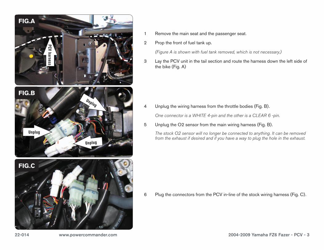
1 Removethemainseatandthepassengerseat.
2 Propthefrontoffueltankup.
(Figure A is shown with fuel tank removed, which is not necessary.)
3 LaythePCVunitinthetailsectionandroutetheharnessdowntheleftsideofthebike(Fig.A)
4 Unplugthewiringharnessfromthethrottlebodies(Fig.B).
One connector is a WHITE 4-pin and the other is a CLEAR 6 -pin.
5 UnplugtheO2sensorfromthemainwiringharness(Fig.B).
The stock O2 sensor will no longer be connected to anything. It can be removed from the exhaust if desired and if you have a way to plug the hole in the exhaust.
6 PlugtheconnectorsfromthePCVin-lineofthestockwiringharness(Fig.C).
FIG.A
FIG.C
PCV harness
Ground wire
Unplug
Unplug
Unplug
FIG.B

22-014 www.powercommander.com 2004-2009 Yamaha FZ6 Fazer - PCV - 4
7 AttachthegroundwireofthePCVtothenegativesideofthebattery(Fig.D).
FIG.D
8 SecurethePCVunitinthetailsectionusingthesuppliedVelcro(Fig.E).
Make sure to clean both surfaces with the alcohol swab before attaching
Optional inputs:
Temperature input-GREEN/WHITEwireof6-pinclearconnectorunderfueltank(sameasPCVconnection).
12v source for Auto-tune-BLUEwireoftaillightconnector.
Speed input-PINKwireofspeedsensorconnector(WHITE3-pinconnectorunderthefueltank).
FIG.E
Ground
FIG.F
9 OnthisbikeitishighlyrecommendedtoconnectthePCVtothespeedinputsothatthemapcanbeputintogearadvancedmode.Todothis,usethesuppliedpieceofwire(WHITE/RED)andposi-taptoconnecttothePINKwireof3-pinWHITEconnectorunderfueltank(Fig.F).
10 ConnecttheotherendofthewireintothePCVSpeedinput-seepage2.
11 Boltthefueltankbackintoplaceandreinstalltheseats.


![Powerpoint Starting to Explore Newspaper Reports [Read-Only]](https://static.fdocuments.net/doc/165x107/623e93c9cb7d3862ad337ae3/powerpoint-starting-to-explore-newspaper-reports-read-only.jpg)


