Please read these instructions completely before starting ...
6
Assembly instructions Roller Shutter, 01/2016 Former instructions lose their validity Page 1 Assembly instructions Roller Shutter Please read these instructions completely before starting assembly. Table of Contents Page 1. Preparatory work / personnel requirements 1 1.1 Check scope of delivery 1 1.2 Required tools and equipment 1 2. Installation of the roller shutter 2 2.1 Installation of guide rails, spring shaft and striker plate 2 2.2 Installation of the aluminum panels and the gate wing 2 2.3 Hang the gate into the guide rails 3 2.4 Placing on the rope, adjusting the roller wheel brackets 3 2.5 Testing and adjusting the spring force 4 3. Finishing work, maintenance and service 4 3.1 Finishing work 4 3.2 Notes on safety and maintenance for your customers 5 3.3 Disposal of disused parts 5 3.4 Service 5 4. Safety and Warning instructions for the installation 5 4.1 Warning information 5 4.2 Safety instructions 5 4.3 Copyright 5 5. Installation drawing DP25 HR 6 Follow this instruction exactly in order to ensure the trouble-free function and a long service life of the rolling gates. An installati- on in accordance with the installation instructions represents the basis for the guarantee in accordance with valid EU law. This instruction explain the installation of Schneider roller shutter: DP25HR/DP25 For this, 1-2 mechanics with training as a vehicle and car body con- structor, or equivalent training, are required depending on the size of kit. • Unload the construction set carefully and exercise caution. Avoid any damages e.g. from impact or the toppling over of component parts. Lifted loads entail hazards! It is important that you observe the safety and warning instructions on page 5. • Do not begin the installation until you have the tools you need and all components with no damages are available. 1.1 Check scope of delivery Check the dispatch for completeness against the enclosed packing list. Please notify the delivery forwarding agent immediately of any damage incurred during transit. We request your understan- ding that we must reserve the right to changes of the scope of delivery in its form, equipment and technology. In case of any uncertainties, get in touch with us immediately. Generally included in the scope of delivery: • 1 pair of horizontal guide rails • 1 pair of vertical guide rails • 1 spring shaft • 1 set aluminum panels (number is indicated on the packing list) • 1 pair of side seals • 1 carton with small parts • These installation instructions, as well as an installation drawing • 1 stick-on label of notes on safety and inspection instructions • 1 spare parts list (partial) The aluminum panels supplied are quality powder-coated on the outer side. Only in case of special customer preference are the pa- nels bright-rolled. Their preparatory treatment requires special care and experience. A guarantee for the paint adhesion is dispensed with in this case. You can also repaint powder-coated rolling gates later through roughening, priming and cover-painting. 1.2 Required tools and equipment Schneider roller shutter can be assembled in every well-equipped workshop. Make sure you have the following equipment and tools ready before beginning the installation:: • Tape measure • Precision compressed air or battery powered screwdriver or drilling machine • 2 vise-grip wrenches • Rivet device and welding device • Hammer • Steel rods approx. 450 mm long • Bolt spanner • Hexagonal socket wrench • Stepladders • Screw clamps • Hand lamp • 2 wood pieces approx. 50 x 50 x 100 mm • Safety shoes and gloves 1. Preparatory work / personnel requirements
Transcript of Please read these instructions completely before starting ...

Assembly instructions Roller Shutter, 01/2016 Former instructions lose their validity Page 1
Assembly instructions
Roller ShutterPlease read these instructions completely before starting assembly.
Table of Contents Page
1. Preparatory work / personnel requirements 11.1 Check scope of delivery 11.2 Required tools and equipment 1
2. Installation of the roller shutter 22.1 Installation of guide rails, spring shaft and striker plate 22.2 Installation of the aluminum panels and the gate wing 22.3 Hang the gate into the guide rails 32.4 Placing on the rope, adjusting the roller wheel brackets 32.5 Testing and adjusting the spring force 4
3. Finishing work, maintenance and service 43.1 Finishing work 43.2 Notes on safety and maintenance for your customers 53.3 Disposal of disused parts 53.4 Service 5
4. Safety and Warning instructions for the installation 54.1 Warning information 54.2 Safety instructions 54.3 Copyright 5
5. Installation drawing DP25 HR 6
Follow this instruction exactly in order to ensure the trouble-free function and a long service life of the rolling gates. An installati-on in accordance with the installation instructions represents the basis for the guarantee in accordance with valid EU law.
This instruction explain the installation of Schneider roller shutter: DP25HR/DP25
For this, 1-2 mechanics with training as a vehicle and car body con-structor, or equivalent training, are required depending on the size of kit.
• Unloadtheconstructionsetcarefullyandexercisecaution. Avoid any damages e.g. from impact or the toppling over of component parts.
Lifted loads entail hazards! It is important that you observe the safety and warning instructions on page 5.
• Donotbegintheinstallationuntilyouhavethetoolsyouneed and all components with no damages are available.
1.1 Check scope of delivery
Check the dispatch for completeness against the enclosed packing list. Please notify the delivery forwarding agent immediately of any damage incurred during transit. We request your understan-ding that we must reserve the right to changes of the scope of delivery in its form, equipment and technology. In case of any uncertainties, get in touch with us immediately.
Generally included in the scope of delivery:
•1 pair of horizontal guide rails•1 pair of vertical guide rails•1 spring shaft•1 set aluminum panels (number is indicated on the packing list)•1 pair of side seals•1 carton with small parts•These installation instructions, as well as an installation drawing•1 stick-on label of notes on safety and inspection instructions•1 spare parts list (partial)
The aluminum panels supplied are quality powder-coated on the outer side. Only in case of special customer preference are the pa-nels bright-rolled. Their preparatory treatment requires special care and experience. A guarantee for the paint adhesion is dispensed with in this case. You can also repaint powder-coated rolling gates later through roughening, priming and cover-painting.
1.2 Required tools and equipment
Schneider roller shutter can be assembled in every well-equipped workshop. Make sure you have the following equipment and tools ready before beginning the installation::
•Tape measure•Precision compressed air or battery powered screwdriver or drilling machine•2 vise-grip wrenches•Rivet device and welding device•Hammer•Steel rods approx. 450 mm long•Bolt spanner•Hexagonal socket wrench •Stepladders•Screw clamps•Hand lamp•2 wood pieces approx. 50 x 50 x 100 mm•Safety shoes and gloves
1. Preparatory work / personnel requirements
Assembly instructions Roller Shutter, 01/2016 Former instructions lose their validity Page 2
2. Installation of the roller shutter
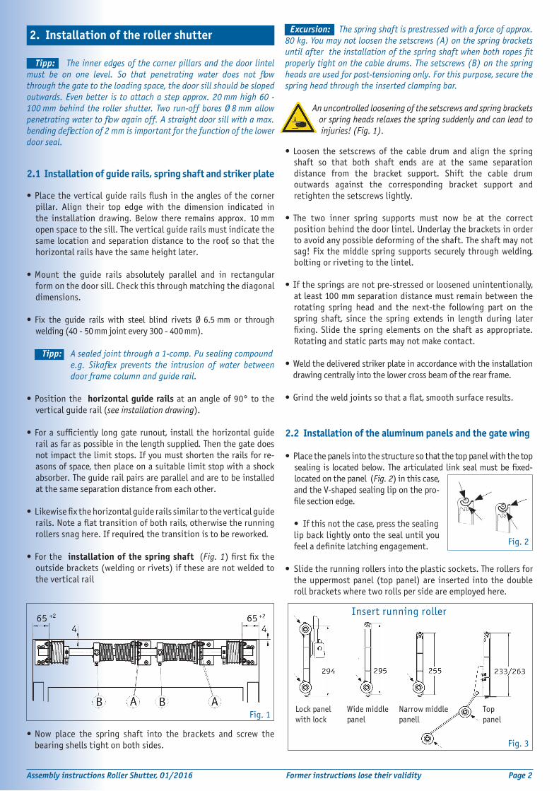
Fig. 1
Fig. 2
Fig. 3
Insert running roller
Lock panel with lock
Wide middle panel
Narrow middle panell
Top panel
Tipp: The inner edges of the corner pillars and the door lintel must be on one level. So that penetrating water does not flow through the gate to the loading space, the door sill should be sloped outwards. Even better is to attach a step approx. 20 mm high 60 - 100 mm behind the roller shutter. Two run-off bores Ø 8 mm allow penetrating water to flow again off. A straight door sill with a max. bending deflection of 2 mm is important for the function of the lower door seal.
2.1 Installation of guide rails, spring shaft and striker plate
•Placetheverticalguiderailsflushintheanglesofthecornerpillar. Align their top edge with the dimension indicated in the installation drawing. Below there remains approx. 10 mm open space to the sill. The vertical guide rails must indicate the same location and separation distance to the roof, so that the horizontal rails have the same height later.
•Mount the guide rails absolutely parallel and in rectangularform on the door sill. Check this through matching the diagonal dimensions.
•Fix the guide rails with steel blind rivets Ø 6.5 mm or through welding (40 - 50 mm joint every 300 - 400 mm).
Tipp: A sealed joint through a 1-comp. Pu sealing compound e.g. Sikaflex prevents the intrusion of water between door frame column and guide rail.
•Positionthe horizontal guide rails at an angle of 90° to the vertical guide rail (see installation drawing).
•For a sufficiently longgate runout, install thehorizontalguide
rail as far as possible in the length supplied. Then the gate does not impact the limit stops. If you must shorten the rails for re-asons of space, then place on a suitable limit stop with a shock absorber. The guide rail pairs are parallel and are to be installed at the same separation distance from each other.
•Likewisefixthehorizontalguiderailssimilartotheverticalguiderails.Noteaflattransitionofbothrails,otherwisetherunning rollers snag here. If required, the transition is to be reworked.
•Forthe installation of the spring shaft (Fig. 1)firstfixtheoutside brackets (welding or rivets) if these are not welded to the vertical rail
•Now place the spring shaft into the brackets and screw the bearing shells tight on both sides.
EExcursion: The spring shaft is prestressed with a force of approx. 80 kg. You may not loosen the setscrews (A) on the spring brackets until after the installation of the spring shaft when both ropes fit properly tight on the cable drums. The setscrews (B) on the spring heads are used for post-tensioning only. For this purpose, secure the spring head through the inserted clamping bar.
An uncontrolled loosening of the setscrews and spring brackets or spring heads relaxes the spring suddenly and can lead to injuries! (Fig. 1).
•Loosen the setscrews of the cable drum and align the springshaft so that both shaft ends are at the same separation distance from the bracket support. Shift the cable drum outwards against the corresponding bracket support and retighten the setscrews lightly.
•The two inner spring supports must now be at the correct positionbehindthedoorlintel.Underlaythebracketsinorderto avoid any possible deforming of the shaft. The shaft may not sag! Fix the middle spring supports securely through welding, bolting or riveting to the lintel.
• Ifthespringsarenotpre-stressedorloosenedunintentionally,at least 100 mm separation distance must remain between the rotating spring head and the next-the following part on the spring shaft, since the spring extends in length during later fixing.Slide the springelementson the shaft asappropriate.Rotating and static parts may not make contact.
•Weldthedeliveredstrikerplateinaccordancewiththeinstallation drawing centrally into the lower cross beam of the rear frame. •Grindtheweldjointssothataflat,smoothsurfaceresults.
2.2 Installation of the aluminum panels and the gate wing
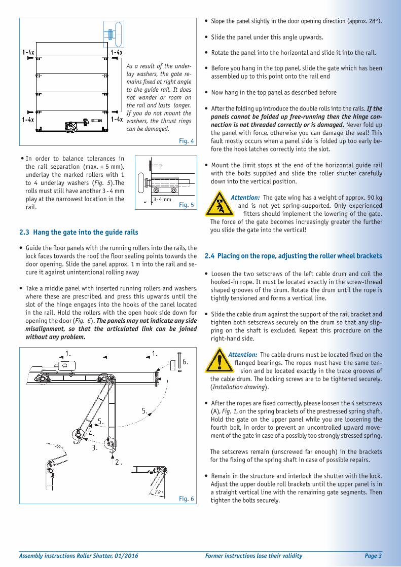
•Placethepanelsintothestructuresothatthetoppanelwiththetop sealingis locatedbelow.Thearticulated linksealmustbefixed- located on the panel (Fig. 2) in this case,
and the V-shaped sealing lip on the pro-filesectionedge.
•Ifthisnotthecase,pressthesealinglip back lightly onto the seal until you feeladefinitelatchingengagement.
•Slidetherunningrollersintotheplasticsockets.Therollersforthe uppermost panel (top panel) are inserted into the double roll brackets where two rolls per side are employed here.
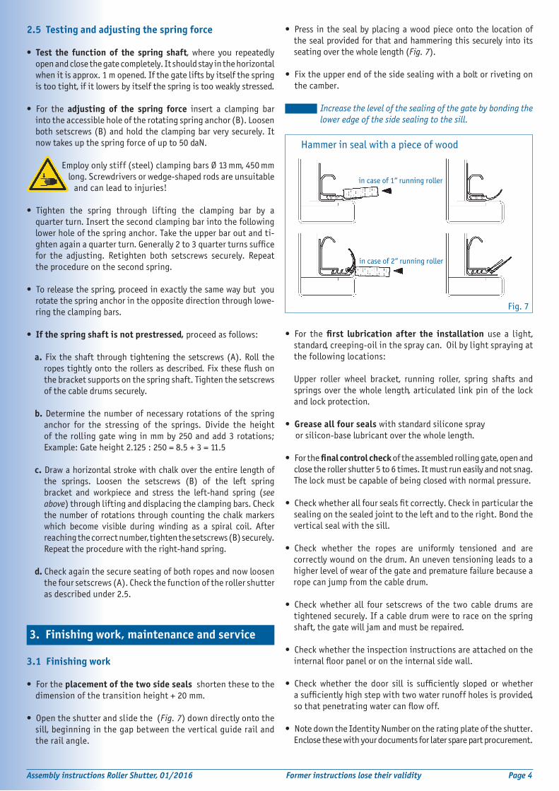
•In order to balance tolerances inthe rail separation (max. + 5 mm), underlay the marked rollers with 1 to 4 underlay washers (Fig. 5).The rolls must still have another 3 - 4 mm
play at the narrowest location in the rail.
2.3 Hang the gate into the guide rails
• Guidethefloorpanelswiththerunningrollersintotherails,thelockfacestowardstheroof,thefloorsealingpointstowardsthedoor opening. Slide the panel approx. 1 m into the rail and se-cure it against unintentional rolling away
• Takeamiddlepanelwithinsertedrunningrollersandwashers,where these are prescribed, and press this upwards until the slot of the hinge engages into the hooks of the panel located in the rail. Hold the rollers with the open hook side down for opening the door (Fig. 6). The panels may not indicate any side misalignment, so that the articulated link can be joined without any problem.
• Slope the panel slightly in the door opening direction (approx. 28°). • Slidethepanelunderthisangleupwards.
• Rotatethepanelintothehorizontalandslideitintotherail.
• Beforeyouhanginthetoppanel,slidethegatewhichhasbeen assembled up to this point onto the rail end
• Nowhanginthetoppanelasdescribedbefore
• Afterthefoldingup,introducethedoublerollsintotherails.If the panels cannot be folded up free-running then the hinge con-nection is not threaded correctly or is damaged. Never fold up the panel with force, otherwise you can damage the seal! This fault mostly occurs when a panel side is folded up too early be-fore the hook latches correctly into the slot.
• Mount the limit stopsat theendof thehorizontalguide railwith the bolts supplied and slide the roller shutter carefully down into the vertical position.
Attention: The gate wing has a weight of approx. 90 kg and is not yet spring-supported. Only experienced fittersshouldimplementtheloweringofthegate.The force of the gate becomes increasingly greater the further you slide the gate into the vertical!
2.4 Placing on the rope, adjusting the roller wheel brackets
• Loosenthe twosetscrewsof the leftcabledrumandcoil thehooked-in rope. It must be located exactly in the screw-thread shaped grooves of the drum. Rotate the drum until the rope is tightly tensioned and forms a vertical line.
• Slidethecabledrumagainstthesupportoftherailbracketandtighten both setscrews securely on the drum so that any slip-ping on the shaft is excluded. Repeat this procedure on the right-hand side.
Attention: Thecabledrumsmustbelocatedfixedonthe flangedbearings.Theropesmusthavethesameten- sion and be located exactly in the trace grooves of the cable drum. The locking screws are to be tightened securely. (Installation drawing).
• Aftertheropesarefixedcorrectly,pleaseloosenthe4setscrews(A), Fig. 1, on the spring brackets of the prestressed spring shaft. Hold the gate on the upper panel while you are loosening the fourth bolt, in order to prevent an uncontrolled upward move-ment of the gate in case of a possibly too strongly stressed spring.
The setscrews remain (unscrewed far enough) in the brackets forthefixingofthespringshaftincaseofpossiblerepairs.
• Remaininthestructureandinterlocktheshutterwiththelock.Adjust the upper double roll brackets until the upper panel is in a straight vertical line with the remaining gate segments. Then tighten the bolts securely.
Assembly instructions Roller Shutter, 01/2016 Former instructions lose their validity Page 3
Fig. 4
As a result of the under-lay washers, the gate re-mains fixed at right angle to the guide rail. It does not wander or roam on the rail and lasts longer. If you do not mount the washers, the thrust rings can be damaged.
Fig. 5
Fig. 6
• Press in thesealbyplacingawoodpieceontothe locationofthe seal provided for that and hammering this securely into its seating over the whole length (Fig. 7).
• Fixtheupperendofthesidesealingwithaboltorrivetingonthe camber.
Tipp : Increase the level of the sealing of the gate by bonding the lower edge of the side sealing to the sill.
• For thefirst lubrication after the installation use a light, standard, creeping-oil in the spray can. Oil by light spraying at the following locations:
Upper roller wheel bracket, running roller, spring shafts andsprings over the whole length, articulated link pin of the lock and lock protection.
• Grease all four seals with standard silicone spray or silicon-base lubricant over the whole length.
• Forthefinal control check of the assembled rolling gate, open andclose the roller shutter 5 to 6 times. It must run easily and not snag. The lock must be capable of being closed with normal pressure.
• Checkwhetherallfoursealsfitcorrectly.Checkinparticularthesealing on the sealed joint to the left and to the right. Bond the vertical seal with the sill.
• Check whether the ropes are uniformly tensioned and arecorrectly wound on the drum. An uneven tensioning leads to a higher level of wear of the gate and premature failure because a rope can jump from the cable drum.
• Checkwhether all four setscrews of the two cable drums aretightened securely. If a cable drum were to race on the spring shaft, the gate will jam and must be repaired.
• Checkwhethertheinspectioninstructionsareattachedontheinternalfloorpanelorontheinternalsidewall.
• Check whether the door sill is sufficiently sloped or whetherasufficientlyhighstepwithtwowaterrunoffholesisprovided,sothatpenetratingwatercanflowoff.
• NotedowntheIdentityNumberontheratingplateoftheshutter.Enclose these with your documents for later spare part procurement.
2.5 Testing and adjusting the spring force
• Test the function of the spring shaft, where you repeatedly open and close the gate completely. It should stay in the horizontal when it is approx. 1 m opened. If the gate lifts by itself the spring is too tight, if it lowers by itself the spring is too weakly stressed.
• For the adjusting of the spring force insert a clamping bar into the accessible hole of the rotating spring anchor (B). Loosen both setscrews (B) and hold the clamping bar very securely. It now takes up the spring force of up to 50 daN.
Employonlystiff(steel)clampingbarsØ13 mm, 450 mm long. Screwdrivers or wedge-shaped rods are unsuitable and can lead to injuries!
• Tighten the spring through lifting the clamping bar by aquarter turn. Insert the second clamping bar into the following lower hole of the spring anchor. Take the upper bar out and ti-ghtenagainaquarterturn.Generally2to3quarterturnssufficefor the adjusting. Retighten both setscrews securely. Repeat the procedure on the second spring.
• Toreleasethespring,proceedinexactlythesamewaybutyourotate the spring anchor in the opposite direction through lowe-ring the clamping bars.
• If the spring shaft is not prestressed, proceed as follows:
a. Fix the shaft through tightening the setscrews (A). Roll theropestightlyontotherollersasdescribed.Fixtheseflushonthe bracket supports on the spring shaft. Tighten the setscrews of the cable drums securely.
b. Determine the number of necessary rotations of the spring anchor for the stressing of the springs. Divide the height of the rolling gate wing in mm by 250 and add 3 rotations; Example:Gateheight2.125:250=8.5+3=11.5
c. Draw a horizontal stroke with chalk over the entire length ofthe springs. Loosen the setscrews (B) of the left spring bracket and workpiece and stress the left-hand spring (see above) through lifting and displacing the clamping bars. Check the number of rotations through counting the chalk markers which become visible during winding as a spiral coil. After reaching the correct number, tighten the setscrews (B) securely. Repeat the procedure with the right-hand spring.
d. Check again the secure seating of both ropes and now loosen the four setscrews (A). Check the function of the roller shutter as described under 2.5.
3.1 Finishing work
• Fortheplacement of the two side seals shorten these to the dimension of the transition height + 20 mm.
• Opentheshutterandslidethe(Fig. 7) down directly onto thesill, beginning in the gap between the vertical guide rail and the rail angle.
Assembly instructions Roller Shutter, 01/2016 Former instructions lose their validity Page 4
3. Finishing work, maintenance and service
Hammer in seal with a piece of wood
in case of 1“ running roller
Fig. 7
in case of 2“ running roller

3.2 Notes on safety and maintenance for your customers
The roller shutter is approx. 70 - 100 kg in weight. Strong springs keep it in equilibrium. Damage can lead to malfunctions and accidents. For your safety and that of your customers, consider these notes and it is absolutely necessary that they be forwarded to your customers:
• Before use check all parts for their secure seating. Loosefixingistoberetightenedorreplaced.
• Checkthewebbingandthetensionropes.Damagedbeltsand tensionropesaretobereplacedimmediately!Usethebeltonly for closing the shutter.
• During use check the interlocking and the opening function. Ifthese are stiff, oil the interlocking of rollers, bearings, hinges, rails and spring shaft with light creeping-oil. Bearing which are not oiled seize up with rust.
• Replacedamagedrollersandhingesimmediately.
•Onlyqualifiedpersonsmayimplementfurtherrepairs.With- out precise knowledge do not attempt to adjust the spring shaft which is under stress or replace damaged ropes yourself. ACCIDENT HAZARD!
• Neverblockofftherailsandgatearea.Whentheshutter is in motion, the gate area must be free of obstacles. Do not activate defective and blocked gates!
ACCIDENT HAZARD!
• Toppling over of the loading space can cause life- threatening accidents! Caution; the gate belt can tear! Therefore never use the belt for ascent or descent.
ACCIDENT HAZARD!
• Beforestartingthedrive,thegatemustbeclosedandlocked. Driving with open gate damages it.
• Lostordamagednotesonsafetyaretobereplaced.Neverpaint over notes on safety!
• High-pressurecleanersoraggressivesolventscandamagethe paint coat and the seals.
• UseonlyoriginalSCHNEIDERspareparts.
• IncaseofretrofittingpartsorchangestoSCHNEIDERcomponent parts, note the corrosion protection and exclude the possibility of contact corrosion through different materials.
3.3 Disposal of disused parts
• Allcomponentpartscanbedeliveredasscrapforrecycling.
3.4 Service
In case of any questions regarding the installation, you are pro-vided with rapid assistance: Tel. +49 (0) 521 - 41 73 12 - 20, E-mail: [email protected]
Please order spare parts either from your responsible sales employee or directly: Tel. +49 (0) 521 - 41 73 12 - 18.
Please send an e-mail to: [email protected]
Assembly instructions Roller Shutter, 01/2016 Former instructions lose their validity Page 5
In order to generate a fault-free roller shutter, it is absolutely neces- sary to adhere to the operating instructions described here, parti- cular the following warning notes, otherwise the warranty is voided.
4.1 Warning information
The intended purpose of the rolling gate is generally not known ex-actly by Schneider. You as a vehicle constructor must the order and further process the construction set according to the requirements ofyourcustomer,aswellascoordinatetheconfigurationdirectivesof the chassis manufacturers.
• Neverinsertscrewsslopeddiagonally!Only connect the compo-nents in direct contact with the supplied screws, and only once! Third-party or used screws risk operational safety and the protec-tion against splashing water. Always use new screws for repairs.
4.2 Safety instructions
Pay attention to your own safety and that of your employees, be-cause working with kits includes hazards such as:
Caution should be exercised in all types of work; in particular, you should:
.. when unloading with a forklift, slide the pallet onto the forklift prongscompletely.Placedownconstructionsetsonflatsurfacesonly and secure them against tilting, tipping over and falling down.
.. Always wear a helmet during crane work and only lift assemblies vertically and not at an angle! Never walk under high loads! The suspension in the crane must always be above the centre of gravity of the assembly!
.. Comply with legal specifications, such as vehicle licensing regulations. This is the responsibility of the vehicle manufacturer.
.. note that component parts can have zinc protrusions and sharp edges. Therefore always wear safety gloves. Likewise you should wear safety shoes since heavy parts can fall down..
4.3 Copyright
The copyright of these instructions belongs to Schneider. It is only intended for the professional installation company and its staff, and contains rules and instructions, which must not be
• reproduced
• disseminated or
• otherwise communicated, in whole or in part.
Infringements may result in civil and criminal penalties!
4. Safety and warning instructions for the installation
• Dangerofcrushing
• Suspendedloads on the crane
• Falling-down load
• Dangeroffalling

Assembly instructions Roller Shutter, 01/2016 Former instructions lose their validity Page 6
Schneider Fahrzeug- und Containertechnik GmbHBrockhagener Straße 92, D-33649 BielefeldTel. + 49 (0)521 - 41 73 11 - 0; Fax: - 90 E-mail: [email protected] www.schneider-fc.de
In case of any questions regarding the installation: Tel. +49 (0)521-41 73 12-20, E-mail: [email protected]
5.
Inst
alla
tion
dra
win
g D
P25
HR
Spr
ing
shaf
t (vi
ew fr
om in
side
)
Se
ctio
n fo
r cl
ose-
off
hook
s
Sa
fety
loc
k
In
side
hei
ght
Pas
sage
cle
aran
ce h
eigh
t
Lint
el h
eigh
t at
leas
t 18
0
Rail
leng
th a
ppro
x. 3
Pass
age
clea
ranc
e w
idth
Insi
de w
idth
Tole
ranc
e +/
- 5
Floo
r se
alin
g