AfterSales Training - Air Cooled Engine Repair
72
AfterSales Training Air Cooled Engine Repair Types: 964 & 993 P10-L ®
-
Upload
michele-colombo -
Category
Documents
-
view
43 -
download
3
description
Porsche air cooled engine repair
Transcript of AfterSales Training - Air Cooled Engine Repair

AfterSales Training Air Cooled Engine RepairTypes: 964 & 993
P10-L
®

Porsche AfterSales Training
Student Name: ________________________________________________
Training Center Location: ________________________________________________
Instructor Name: ________________________________________________
Date: ___________________
Important Notice:The contents of this AfterSales Training brochure was originally written by Porsche AG for its rest-of-worldEnglish speaking market. The electronic text and graphic files were then imported by Porsche Cars N.A, Inc. and edited for con-tent. Some equipment and technical data listed in this publication may not be applicable for our market. Specifications are sub-ject to change without notice.
We have attempted to render the text within this publication to American English as best as we could. We reserve the right tomake changes without notice.
© 2004 Porsche Cars North America, Inc. All Rights Reserved. Reproduction or translation in whole or in part is not permittedwithout written authorization from publisher. AfterSales Training Publications
Dr. Ing. h.c. F. Porsche AG is the owner of numerous trademarks, both registered and unregistered, including without limitationthe Porsche Crest®, Porsche®, Boxster®, Carrera®, Cayenne®, Tiptronic®, VarioCam®, PCM®, 911®, 4S®, and the modelnumbers and distinctive shapes of Porsche’s automobiles such as, the federally registered 911 automobile. The third party trade-marks contained herein are the properties of their respective owners. Porsche Cars North America, Inc., believes the specifica-tions to be correct at the time of printing. However, specifications, standard equipment and options are subject to change with-out notice.
Part Number - PNA P10 L01 Edition -6/04

Table of Contents
Air Cooled Engine Repair
Description Page
Engine Type Designations . . . . . . . . . . . . . . . . . . . . . . . . . . . . . . . . . . . . . . . . . . . . . . . . . . . . .1
911 Carrera (964) Engine . . . . . . . . . . . . . . . . . . . . . . . . . . . . . . . . . . . . . . . . . . . . . . . . . . . .5
911 Carrera (993) Engine . . . . . . . . . . . . . . . . . . . . . . . . . . . . . . . . . . . . . . . . . . . . . . . . . . .49
Conversion Charts . . . . . . . . . . . . . . . . . . . . . . . . . . . . . . . . . . . . . . . . . . . . . . . . . . . . . . . . .65

Air Cooled Engine Repair
Engine Type Designations
Air Cooled Engine Repair Page 1
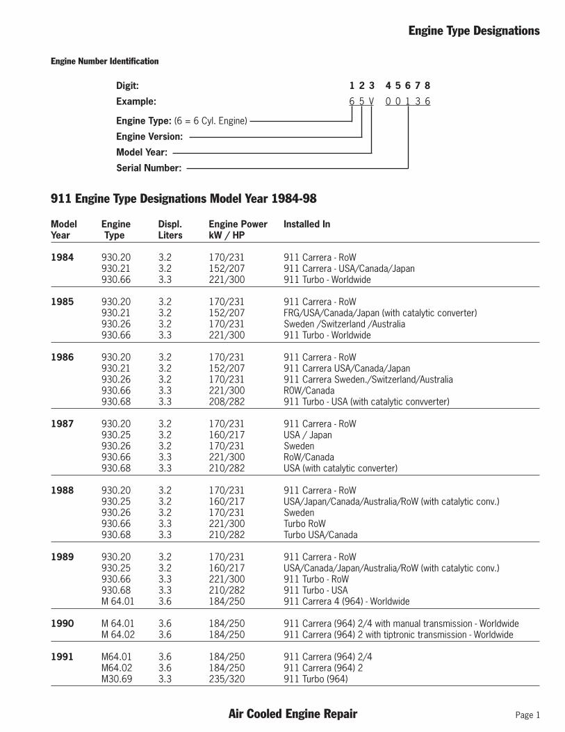
911 Engine Type Designations Model Year 1984-98
Model Engine Displ. Engine Power Installed InYear Type Liters kW / HP
1984 930.20 3.2 170/231 911 Carrera - RoW930.21 3.2 152/207 911 Carrera - USA/Canada/Japan930.66 3.3 221/300 911 Turbo - Worldwide
1985 930.20 3.2 170/231 911 Carrera - RoW930.21 3.2 152/207 FRG/USA/Canada/Japan (with catalytic converter)930.26 3.2 170/231 Sweden /Switzerland /AustraIia930.66 3.3 221/300 911 Turbo - Worldwide
1986 930.20 3.2 170/231 911 Carrera - RoW930.21 3.2 152/207 911 Carrera USA/Canada/Japan930.26 3.2 170/231 911 Carrera Sweden./Switzerland/Australia930.66 3.3 221/300 R0W/Canada930.68 3.3 208/282 911 Turbo - USA (with catalytic convverter)
1987 930.20 3.2 170/231 911 Carrera - RoW930.25 3.2 160/217 USA / Japan930.26 3.2 170/231 Sweden930.66 3.3 221/300 RoW/Canada930.68 3.3 210/282 USA (with catalytic converter)
1988 930.20 3.2 170/231 911 Carrera - RoW930.25 3.2 160/217 USA/Japan/Canada/Australia/RoW (with catalytic conv.)930.26 3.2 170/231 Sweden930.66 3.3 221/300 Turbo RoW930.68 3.3 210/282 Turbo USA/Canada
1989 930.20 3.2 170/231 911 Carrera - RoW930.25 3.2 160/217 USA/Canada/Japan/Australia/RoW (with catalytic conv.)930.66 3.3 221/300 911 Turbo - RoW930.68 3.3 210/282 911 Turbo - USAM 64.01 3.6 184/250 911 Carrera 4 (964) - Worldwide
1990 M 64.01 3.6 184/250 911 Carrera (964) 2/4 with manual transmission - WorldwideM 64.02 3.6 184/250 911 Carrera (964) 2 with tiptronic transmission - Worldwide
1991 M64.01 3.6 184/250 911 Carrera (964) 2/4M64.02 3.6 184/250 911 Carrera (964) 2M30.69 3.3 235/320 911 Turbo (964)
Engine Number Identification
Digit: 1 2 3 4 5 6 7 8
Example: 6 5 V 0 0 1 3 6
Engine Type: (6 = 6 Cyl. Engine)
Engine Version:
Model Year:
Serial Number:

Page 2 Air Cooled Engine Repair
Engine Type Designations
Model Engine Displ. Engine Power Installed InYear Type Liters kW / HP
1992 M64.01 3.6 184/250 911 Carrera (964) 2/4M64.02 3.6 184/250 911 Carrera (964) 2M64.03 3.6 191/260 911 Carrera (964) RSM30.69 3.3 235/320 911 Turbo (964)
1993 M64.01 3.6 184/250 911 Carrera (964) 2/4M64.02 3.6 184/250 911 Carrera (964) 2M64.03 3.6 191/260 911 Carrera (964) RS M64.50 3.6 265/360 911 Turbo (964)
1994 M64.01 3.6 184/250 911 Carrera (964) 2/4 USAM64.02 3.6 184/250 911 Carrera (964) 2 USAM64.05 3.6 200/272 911 Carrera (964) RoWM64.06 3.6 200/272 911 Carrera (964) RoW & Taiwan with TiptronicM64.50 3.6 265/355 911 Turbo USA/CDN
1995 M64.05 3.6 200/272 911 Carrera (964) RoW M64.06 3.6 200/272 911 Carrera (964) RoW M64.20 3.7 220/300 911 Carrera (993) RS RoWM64.07 3.6 200/272 911 Carrera (993) USA M64.08 3.6 200/272 911 Carrera (993) USA
1996 M64.21 3.6 210/285 911 Carrera (993) /C4 /C4S RoW M64.22 3.6 210/285 911 Carrera (993) RoW Tiptronic M64.23 3.6 210/285 911 Carrera (993) /C4/C4S USAM64.24 3.6 210/285 911 Carrera (993) USA TiptronicM64.60 3.6 300/408 911 Turbo (993) RoW and USA/CDN
1997 M64.21 3.6 210/285 911 Carrera (993) /C4 /C4S RoW M64.22 3.6 210/285 911 Carrera (993) RoW Tiptronic M64.23 3.6 210/285 911 Carrera (993) /C4/C4S USAM64.24 3.6 210/285 911 Carrera (993) USA TiptronicM64.60 3.6 300/408 911 Turbo (993) RoW and USA/CDN
1998 M64.21 3.6 210/285 911 Carrera (993) /C4/C4S RoW M64.22 3.6 210/285 911 Carrera (993) RoW Tiptronic M64.23 3.6 210/285 911 Carrera (993) /C4 & C4S USA/CDNM64.24 3.6 210/285 911 Carrera (993) USA/CDN TiptronicM64.60 3.6 300/408 911 Turbo (993) RoW and USA/CDN

Engine Type Designations
Air Cooled Engine Repair Page 3
Notes: Notes:

Page 4 Air Cooled Engine Repair
Engine Type Designations
Notes: Notes:

911 Carrera (964) Engine
Air Cooled Engine Repair Page 5
Subject Page
General Information . . . . . . . . . . . . . . . . . . . . . . . . . . . . . . . . . . . . . . . . . . . . . . . . . . . . . . . . .7
Engine M64.01/02 . . . . . . . . . . . . . . . . . . . . . . . . . . . . . . . . . . . . . . . . . . . . . . . . . . . . . . . . .7
Engine M64.01/02 Engine Data . . . . . . . . . . . . . . . . . . . . . . . . . . . . . . . . . . . . . . . . . . . . . . . .9
Crankcase . . . . . . . . . . . . . . . . . . . . . . . . . . . . . . . . . . . . . . . . . . . . . . . . . . . . . . . . . . . . . .10
Connecting Rods . . . . . . . . . . . . . . . . . . . . . . . . . . . . . . . . . . . . . . . . . . . . . . . . . . . . . . . . . .11
Pistons . . . . . . . . . . . . . . . . . . . . . . . . . . . . . . . . . . . . . . . . . . . . . . . . . . . . . . . . . . . . . . . . .11
Cylinders . . . . . . . . . . . . . . . . . . . . . . . . . . . . . . . . . . . . . . . . . . . . . . . . . . . . . . . . . . . . . . . .12
Knock Bridge . . . . . . . . . . . . . . . . . . . . . . . . . . . . . . . . . . . . . . . . . . . . . . . . . . . . . . . . . . . .13
Pulley . . . . . . . . . . . . . . . . . . . . . . . . . . . . . . . . . . . . . . . . . . . . . . . . . . . . . . . . . . . . . . . . . .13
Cylinder Head . . . . . . . . . . . . . . . . . . . . . . . . . . . . . . . . . . . . . . . . . . . . . . . . . . . . . . . . . . . .14
Valves . . . . . . . . . . . . . . . . . . . . . . . . . . . . . . . . . . . . . . . . . . . . . . . . . . . . . . . . . . . . . . . . . .15
Camshaft Housing . . . . . . . . . . . . . . . . . . . . . . . . . . . . . . . . . . . . . . . . . . . . . . . . . . . . . . . . .16
Chain Drive . . . . . . . . . . . . . . . . . . . . . . . . . . . . . . . . . . . . . . . . . . . . . . . . . . . . . . . . . . . . . .17
Chain Tensioners . . . . . . . . . . . . . . . . . . . . . . . . . . . . . . . . . . . . . . . . . . . . . . . . . . . . . . . . . .19
Engine Lubrication . . . . . . . . . . . . . . . . . . . . . . . . . . . . . . . . . . . . . . . . . . . . . . . . . . . . . . . . .20
Oil Thermostat . . . . . . . . . . . . . . . . . . . . . . . . . . . . . . . . . . . . . . . . . . . . . . . . . . . . . . . . . . . .21
Cooling . . . . . . . . . . . . . . . . . . . . . . . . . . . . . . . . . . . . . . . . . . . . . . . . . . . . . . . . . . . . . . . . .22
Exhaust System . . . . . . . . . . . . . . . . . . . . . . . . . . . . . . . . . . . . . . . . . . . . . . . . . . . . . . . . . . .23
Engine Paneling . . . . . . . . . . . . . . . . . . . . . . . . . . . . . . . . . . . . . . . . . . . . . . . . . . . . . . . . . . .24
Engine Suspension . . . . . . . . . . . . . . . . . . . . . . . . . . . . . . . . . . . . . . . . . . . . . . . . . . . . . . . .25
Technical Data . . . . . . . . . . . . . . . . . . . . . . . . . . . . . . . . . . . . . . . . . . . . . . . . . . . . . . . . . . . .27
Engine Tolerances and Specifications . . . . . . . . . . . . . . . . . . . . . . . . . . . . . . . . . . . . . . . . . . .30
Setting Engine Timing . . . . . . . . . . . . . . . . . . . . . . . . . . . . . . . . . . . . . . . . . . . . . . . . . . . . . .43

Page 6 Air Cooled Engine Repair
911 Carrera (964) Engine
Notes: Notes:

911 Carrera (964) Engine
Air Cooled Engine Repair Page 7
Engines
General
The 1984 - 911 Carrera 3.2 liter engine featured thefollowing changes from the prevoius 911 SC engine:
l Displacement increased by changing stroke from 70.4to 74.4 mm
l New crankcase with improved basic strength and newsealing cap for intermediate shaft
l Crankshaft from 911 Turbo with modified flywheel instal-lation
l New flywheel for DMEl New connecting rods (unchanged from 911 Turbo)l New drive belt pulleyl New pistonsl New cylindersl Modified cylinder headsl New chain tensioner with hydraulic damping via lubricat-
ing oil circuitl Modified lubricating circuitl New crankcase and oil tank ventingl Fan wheel with ventilation slotsl Modifications on heater blower, heat exchanger and
exhaust systeml Combination of fuel injection and ignition in DME (Digital
Motor Electronics)
Yearly Changes
1986 Modell Turbo engine with catalytic converter only for USA
1987 Modell Cylinder head tightened with torque and torque angle =
15 Nm and 1 x 90 (retroactively since 1984 models)
1988 Modell Conrod bolts tightened with torque and torque angle =
20 Nm and 1 x 90°
1989 Modell 911 Carrera (no modifications)l 911 Carrera 4 (964) (introduction)
1990 Modell 911 Carrera 2 (964) (introduction) with rear wheel
drive, 5-speed manual or Tiptronic transmissionEngine Types:M64.01 - Manual TransmissionM64.02 - Tiptronic Transmission
l Stronger piston pin circlipsl M 64.02 changed ratio for cooling fan
Engine M64.01/02 – 911 Carrera 2/4 (964) 1989-94)
The engine 911 Carrera (964) engine is a further develop-ment of the previous 911 Carrera engine.
l One engine type worldwidel Double ignition, i.e. two spark plugs for each
combustion chamberl Knock regulationl Exhaust ports in cylinder heads designed as ceramic
port linersl Camshaft drive with help of duplex roller chains,
hydraulic chain tensioner acting on tensioning rails andadditional guide rails
l Vibration damper on crankshaftl Separate drive for engine fan and alternatorl Oil Cooler with two-stage blower in front end of car on
right-hand sidel Two-stage resonance intake systeml Digital Motor Electronics (DME)
Notes:

Page 8 Air Cooled Engine Repair
911 Carrera (964) Engine
Engine Type M64.01/02 Components
1 - Hot air blower2 - Throttle valve assembly3 - Resonance flap control switch4 - Air Cleaner5 - Electric tank venting valve6 - Air conditioner compressor7 - Fuel feed pipe8 - Fuel collection pipe, right9 - Final muffler10 - Tailpipe11 - Engine carrier12 - Intermediate muffler13 - Drive belt tightness monitor14 - Double ignition distributor15 - Heating control temperature switch
Engine Type M64.01/02 Components
16 - Air flow sensor17 - Idle speed control18 - Bypass air pipe for oil tank venting19 - Combination oil temperature and pressure switch20 - Heat exchanger, left21 - Heat exchanger, right22 - Engine oil feed from oil tank to engine23 - Power steering pump24 - Engine oil return to thermostat25 - Engine cover, right26 - Vacuum reservoir for resonance flap control
Engine Type M64.01/02 Components
27 - Crankcase venting28 - Oil tank venting29 - Fuel tank venting30 - Speed sender31 - Knock sensor 132 - NTC 233 - Fuel pressure testing connection34 - Fuel return pipe35 - Oxygen sensor36 - Catalytic converter37 - Fuel injector38 - Fuel collection pipe, left39 - Carbon canister connection40 - Heater blower control resistor
Notes:

911 Carrera (964) Engine
Air Cooled Engine Repair Page 9
Longitudinal Section of the Engine
Engine Type M64.01/02 Side View Cutout
Cross Section of the Engine
Engine Type M64.01/02 Front View Cutout
Notes:
Full-Load curve of the M64.01/02
Engine Data
Displacement 3.6 I (76.4 mm stroke, 100 mm bore dia.)Rated power 184 kW / 247 H.P. SAE NETRated speed 6100 rpmMax. torque at 4800 rpm 195 ft. lb. (310 Nm)Compression ratio 11.3 to 1Fuel grade 98 RON/88 MON (Premium Unleaded)
Notes:

Page 10 Air Cooled Engine Repair
911 Carrera (964) Engine
Crankcase
Arrow points to new rib.
The two-piece crankcase made of an aluminum/silicon al-loy now has a rib as a guide for cooling air (arrow).
Location of oil spray jet.
The adapting diameter on the cylinder base is 106.8 mm.2 mm diameter oil spray jets are provided in the crank-case for cooling of pistons (arrow).
Notes:
Crankcase Mounting Bolts
Crankcase Bolt Components
1 - Crankcase bolt2 - Insulator3 - Round seal4 - Multiple-tooth nut
The mating surfaces of both crankcase sections aresealed with Loctite No. 574. Crankcase bolts are tight-ened with a torque of 40 Nm. The tightening torque forother mounting bolts is 23 Nm.
Crankcase, Bolting
Installation Sequence of Studs with Special Tool 9511.
1 - Lubricate all studs (1) and round seals (3) with oil.2 - Place insulator (2) on stud (1).3 - Guide round seal (3) with tapered sleeve over the
threaded zone and push on to head end of the boltshaft (see Figure 1).
4 - Prepare the remaining studs accordingly.5 - Insert studs (1) in to the crankcase against the
mechanical stop.6 - Install tapered sleeve with mounted round seal (3) on
the threaded end. Slide round seal with the B-end ofthe cylindrical sleeve off of the tapered sleeve. Pull offtapered sleeve and slide round seal with the A-end ofthe cylindrical sleeve into final position (see Figure 2).
Note: Only slight force may be applied for this step. Coun-terhold on the head.
7 - Install insulator (2) dry and multi-tooth nut (4) lubricatedwith oil.
8 - Counterhold on the bolt head while tightening the multi-tooth nut. Tightening torque = 40 Nm.
9 - Continue with the remaining studs in the same manner(check the tightening sequence). Tightening torque forother bolts = 23 Nm.
911 Carrera (964) Engine
Air Cooled Engine Repair Page 11
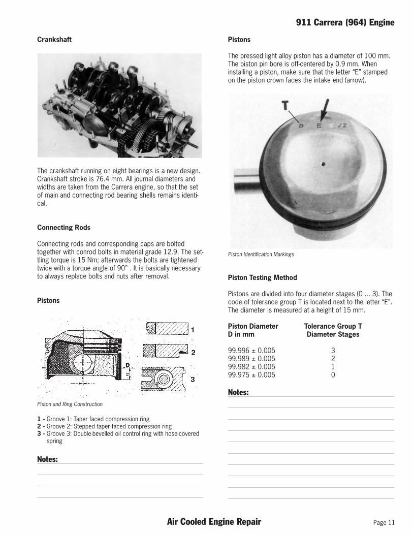
Crankshaft
The crankshaft running on eight bearings is a new design.Crankshaft stroke is 76.4 mm. All journal diameters andwidths are taken from the Carrera engine, so that the setof main and connecting rod bearing shells remains identi-cal.
Connecting Rods
Connecting rods and corresponding caps are boltedtogether with conrod bolts in material grade 12.9. The set-tling torque is 15 Nm; afterwards the bolts are tightenedtwice with a torque angle of 90° . It is basically necessaryto always replace bolts and nuts after removal.
Pistons
Piston and Ring Construction
1 - Groove 1: Taper faced compression ring2 - Groove 2: Stepped taper faced compression ring3 - Groove 3: Double-bevelled oil control ring with hose-covered
spring
Notes:
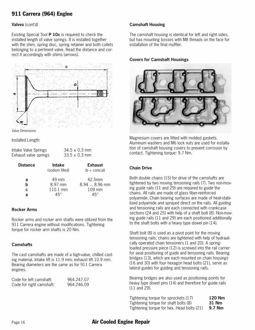
Pistons
The pressed light alloy piston has a diameter of 100 mm.The piston pin bore is off-centered by 0.9 mm. Wheninstalling a piston, make sure that the letter “E” stampedon the piston crown faces the intake end (arrow).
Piston Identification Markings
Piston Testing Method
Pistons are divided into four diameter stages (0 ... 3). Thecode of tolerance group T is located next to the letter “E”.The diameter is measured at a height of 15 mm.
Piston Diameter Tolerance Group TD in mm Diameter Stages
99.996 ± 0.005 399.989 ± 0.005 299.982 ± 0.005 199.975 ± 0.005 0
Notes:

Page 12 Air Cooled Engine Repair
911 Carrera (964) Engine
Cylinders
The cylinders with a bearing surface diameter of 100 mmare made of a high temperature light alloy. The actualbearing surface coat (Mahle - Nikasil) is appliedgalvanically.
Cylinders are designed with a slight conical effect in theupper bearing surface zone due to the varying thermicloads. The cylinder bore is smaller by about 0.03 mm inthe area of the upper reversing point of the piston. Around silicon seal is used for sealing the cylinder base.
Notes:
Cylinder Testing Method
Cylinder Measurement Points
Height H Cyl. Dia. D Tolerance Group T/in mm in mm Diameter Stages(- 0.020) (+ 0.007)
82.770 100.021 6/382.770 100.014 6/282.770 100.007 6/182.770 100.000 6/0
82.750 100.021 5/382.750 100.014 5/282.750 100.007 5/182.750 100.000 5/0
In order to be able to determine the correct cylindergroup, distance H is measured first and classified in heightgroups 5 and 6. Each height group (5 or 6) is subdividedinto diameter stages of 0 ... 3.
The pertinent cylinder diameter (D) is measured at a heightof 56 mm.
Only cylinders of the same height group (5 or 6) may be in-stalled on one side of the engine. The pertinent tolerancegroup (T) is die-stamped on the knock bridge mountingboss on the opposite side.

911 Carrera (964) Engine
Air Cooled Engine Repair Page 13
Knock Bridge
One knock bridge (arrow), which holds a knock sensor, ismounted on the bosses cast on the cylinders for eachbank of cylinders.
Knock Sensor Bridge (arrow)
There must be conformance with the following sequenceof installation.
1. Mount cylinders 1 ... 3 or 4 ... 6.2. Mount knock bridges and screw in three M6 mounting
screws.3. Mount cylinder heads and tighten4. Tighten M6 screws of knock bridges. Tightening torque
= 9.7 Nm.
Pulley with Vibration Damper
Crankshaft Pulley
Crankshaft Pulley Components
A pulley assembly including torsional vibration damper (1)is mounted on the rear end of the crankshaft with help of acone connector. The vibration damper has the task ofcushioning the engine’s rotational oscillation, which is pro-duced by mass and gas forces.
This is accomplished with a rotation mass, which isconnected with steel hub (2) in a rotational elastic mannerwith help of a vulcanized rubber ring (3). The damper usesits own oscillation to oppose and considerably cushion theoscillation of the engine.
The rotation body of the vibration damper is used simulta-neously as a pulley for the drive of A/C compressor (4).Both of the other pulley grooves are used to drive the fan(6) as well as for separate drive of alternator (5).

Page 14 Air Cooled Engine Repair
911 Carrera (964) Engine
Pulley with Vibration Damper (cont’d)
Dowel pin (7) determines the position of pulleys to thecrankshaft. This is necessary, because there are TDCmarks for the different cylinders (3 notches with 120°spacing between each). The notch for cylinder no. 1 (igni-tion TDC) is marked additionally with Z 1.
The M14 x 1.5 central bolt (8) must be tightened to atorque of 235 Nm. Since the vibration damper and pulleysare balanced together, they should never bedisassembled.
Intermediate Shaft
The steel intermediate shaft gear wheel is paired with thecontrol gear wheel on the crankshaft to guaranteeoptimum smooth running. Both gear wheels are suppliedas a set without a pairing number.
Arrow Shows Markings
Sprockets on the intermediate shaft for drive of thecamshaft are made of sintered steel. The number (arrow)on the intermediate shaft gear wheel is a code fortolerance group 0 or 1 (distance between shafts in thecrankcase).
Notes:
Cylinder Head
Cooling ribs have been modified to optimize the flow ofcooling air in the area of the cylinder head.
Cylinder Head Cutout
Ceramic port liners (1) are inserted in the exhaust ports ofthe cylinder head. These port liners reduce thetemperature on the cylinder head by about 40° C.
Sealing Groove (arrow)
The threads and bearing surfaces of the multiple-toothnuts of the cylinder head bolts must be coated withOptimoly HT. The setting torque is 15 Nm; afterwards theyare tightened once to a torque angle of 90°.
Filling seals are used for sealing on the exhaust end of theexhaust manifold. A corresponding groove (arrow) is pro-vided on the cylinder head end.

911 Carrera (964) Engine
Air Cooled Engine Repair Page 15
Cylinder Head
A triple hole flange with studs (arrow) is used on the intakeend due to the altered position of fuel injectors.
Intake Manifold Sealing Surface
Spark Plugs
The wrench size for spark plugs is 16 mm. A pertinentspark plug wrench is included with the car tools.
Notes:
Valves
Valve Layout
1 - Intake valve2 - Exhaust valve
Intake valves are filled with sodium to improve the transferof heat from intake valves to the cylinder head. This mea-sure is not necessary for exhaust valves, since they havea more homogeneous distribution of heat.
Valve seals are pressed in against stop (max. 2000 N) andhave a locking groove for the shaft seal.
Notes:
Page 16 Air Cooled Engine Repair
911 Carrera (964) Engine
Valves (cont’d)
Existing Special Tool P 10c is required to check theinstalled length of valve springs. It is installed togetherwith the shim, spring disc, spring retainer and both colletsbelonging to a pertinent valve. Read the distance and cor-rect it accordingly with shims (arrows).
Valve Dimensions
Installed Length:
Intake Valve Springs 34.5 ± 0.3 mmExhaust valve springs 33.5 ± 0.3 mm
Distance Intake Exhaust(sodium filled) (b = conical)
a 49 mm 42.5mmb 8.97 mm 8.94 ... 8.96 mmc 110.1 mm 109 mma 45° 45°
Rocker Arms
Rocker arms and rocker arm shafts were utilized from the911 Carrera engine without modifications. Tighteningtorque for rocker arm shafts is 20 Nm.
Camshafts
The cast camshafts are made of a high-value, chilled cast-ing material. Intake lift is 11.9 mm; exhaust lift 10.9 mm.Bearing diameters are the same as for 911 Carreraengines.
Code for left camshaft: 964.247.07Code for right camshaft: 964.246.09
Camshaft Housing
The camshaft housing is identical for left and right sides,but has mounting bosses with M8 threads on the face forinstallation of the final muffler.
Covers for Camshaft Housings
Magnesium covers are fitted with molded gaskets.Aluminum washers and M6 lock nuts are used for installa-tion of camshaft housing covers to prevent corrosion bycontact. Tightening torque: 9.7 Nm.
Chain Drive
Both double chains (15) for drive of the camshafts aretightened by two moving tensioning rails (7). Two non-mov-ing guide rails (11 and 29) are required to guide thechains. All rails are made of glass fiber-reinforcedpolyamide. Chain bearing surfaces are made of heat-stabi-lized polyamide and sprayed direct on the rails. All guidingand tensioning rails are each connected with crankcasesections (24 and 25) with help of a shaft bolt (8). Non-mov-ing guide rails (11 and 29) are each positioned additionallyto the shaft bolts with a heavy type dowel pin (14).
Shaft bolt (8) is used as a pivot point for the movingtensioning rails; chains are tightened with help of hydrauli-cally operated chain tensioners (1 and 20). A spring-loaded pressure piece (12) is screwed into the rail carrierfor axial positioning of guide and tensioning rails. Bearingbridges (13), which are each mounted on chain housings(16 and 30) with four hexagon head bolts (21), serve aslateral guides for guiding and tensioning rails.
Bearing bridges are also used as positioning points forheavy type dowel pins (14) and therefore for guide rails(11 and 29).
Tightening torque for sprockets (17) 120 NmTightening torque for shaft bolts (8) 31 NmTightening torque for hex. Head bolts (21) 9.7 Nm

911 Carrera (964) Engine
Air Cooled Engine Repair Page 17
Chain Drive Layout
1 - Chain Tensioner2 - Gasket For Chain Tensioner3 - Cover For Chain Tensioner4 - Aluminum Washer5 - M6 Lock Nut6 - Gasket For Chain Housing7 - Tensioning Rail8 - Shaft Bolt9 - Distributor Drive Gear10 - Control Sprocket On Crankshaft (34 Teeth)11 - Guide Rail, Right12 - Spring-loaded Pressure Piece13 - Bearing Bridge14 - Dowel Pin15 - Duplex Roller Chain16 - Chain Housing, Right17 - Sprocket (28 Teeth)18 - M12 X 1.5 Hex Bolt19 - Dowel Pin (6mm Dia.)20 - Chain Tensioner, Right21 - M6 Hex Head Screw22 - Sprocket (24 Teeth)23 - Intermediate Shaft Sprocket (60 Teeth)24 - Crankcase Section, Right25 - Crankcase Section, Left26 - Dowel Sleeve27 - Aluminum Washer28 - M8 Lock Nut29 - Guide Rail, Left30 - Chain Housing, Left
Page 18 Air Cooled Engine Repair
911 Carrera (964) Engine
Chain Housings
Right Chain Housing
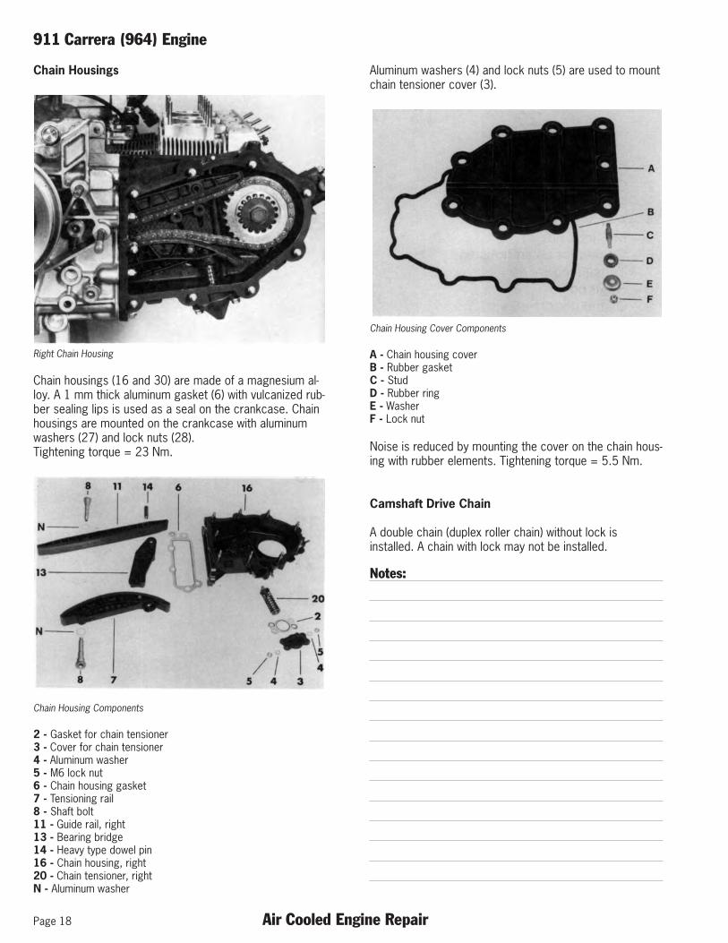
Chain housings (16 and 30) are made of a magnesium al-loy. A 1 mm thick aluminum gasket (6) with vulcanized rub-ber sealing lips is used as a seal on the crankcase. Chainhousings are mounted on the crankcase with aluminumwashers (27) and lock nuts (28). Tightening torque = 23 Nm.
Chain Housing Components
2 - Gasket for chain tensioner3 - Cover for chain tensioner4 - Aluminum washer5 - M6 lock nut6 - Chain housing gasket7 - Tensioning rail8 - Shaft bolt11 - Guide rail, right13 - Bearing bridge14 - Heavy type dowel pin16 - Chain housing, right20 - Chain tensioner, rightN - Aluminum washer
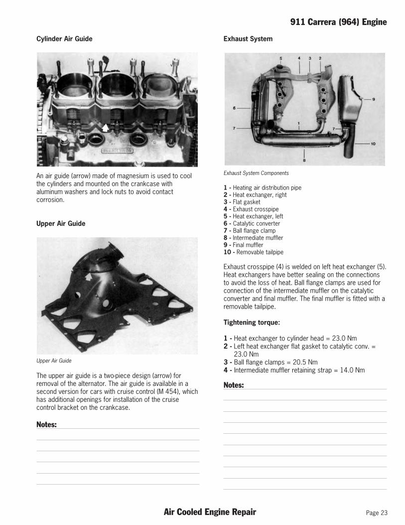
Aluminum washers (4) and lock nuts (5) are used to mountchain tensioner cover (3).
Chain Housing Cover Components
A - Chain housing coverB - Rubber gasketC - StudD - Rubber ringE - WasherF - Lock nut
Noise is reduced by mounting the cover on the chain hous-ing with rubber elements. Tightening torque = 5.5 Nm.
Camshaft Drive Chain
A double chain (duplex roller chain) without lock isinstalled. A chain with lock may not be installed.
Notes:

911 Carrera (964) Engine
Air Cooled Engine Repair Page 19
Chain Tensioners
1 - Chain tensioner, left20 - Chain tensioner, right
G - Housing (cylinder)H - PistonJ - CirclipK - SpringL - Spring retainerM - Circlip
Chain tensioners have the task of cushioning the vibrationof timing chains. They work with help of hydraulic cushion-ing and a return spring, and are connected direct in thecamshaft housing oil supply circuit.
Chain tensioners are each held in position by a coverbolted on the chain housing. Oil is supplied to the leftchain tensioner by a piston, whereby the oil reaches theworking chamber of the chain tensioner through a checkvalve located in the piston.
The right chain tensioner is supplied with oil via the hous-ing. The check valve, consisting of a valve ball, valvespring and valve cage, is located in the housing.
P - CirclipR - Valve ballS - Valve SpringT - Valve cage
The check valve opens with a pressure of 0.2 bar. The pis-ton of the chain tensioner has an axially ground surface onthe cylindrical section, 3 mm wide for the left side and ap-proximately 1 mm wide for the right side. Oil can escapeout of the working chamber through a leak gap producedin this manner and by the play between the piston andhousing, through which the cushioning degree isdetermined.
The chain tensioner is pressed apart and the chain is ten-sioned, if the force during operation of the engine, whichthe chain exerts on the chain tensioner, is less than the oilpressure plus chain force. If chain forces are greater thanthe oil pressure plus spring force, the chain tensioner ispressed together or the piston is moved against the oilcushion in the working chamber. Oil can escape via theleak gap and piston/housing clearance, through whichchain motion is cushioned. The leak gap also guaranteesbleeding of the working chamber
When installing it is important to make sure that the chaintensioner piston always faces up. The left chain tensioneris 8 mm longer because of the design.
Notes:

Page 20 Air Cooled Engine Repair
911 Carrera (964) Engine
Engine Lubrication
Oil System Layout
1 - Oil tank2 - Oil supply pipe3 - Crankcase (engine)4 - Oil return pipe, rear5 - Oil filter5a - Oil filter flange6 - Oil return pipe, front7 - Oil thermostat8 - Oil cooler supply pipe9 - Oil cooler with two-stage blower10 - Oil cooler return pipe11 - Oil return hose12 - Oil drain hose (molded)13 - Cowl14 - Crankcase venting pipe with 6 mm dia. orifice in oil
tank15 - Bypass air pipe with 1.5 mm dia. orifice in oil tank16 - Throttle valve assembly17 - Oil tank venting pipe
Notes:
Oil Pump
The oil pump has a magnesium alloy body. The intake suc-tion rate is greater in order to return the oil from thecrankcase to the oil tank faster. The pressure stage has adelivery rate of about 65 liters per minute. Tighteningtorque for oil pump on crankcase = 23 Nm.
Oil Pipes
Oil supply pipes for chain tensioners and camshafthousings are integrated in the chain housings. The oil sup-ply pipe to the camshaft housing has a 2.5 mm dia.orifice. This reduces the oil flow rate to the camshaft hous-ing by about 50%, which in turn prevents foaming of theoil. The oil filter is located in the right rear return pipe. Oilfilter flange and oil pipe are mounted on the body with helpof rubber elements in the interest of noise reduction.
Oil Cooler
The oil cooler fitted with a two-stage blower is locatedahead of the right front wheel. The first blower stage cutsin at 105° C; the second blower stage at an oiltemperature of 118° C.
Oil Tank
The stainless steel oil tank is positioned ahead of the rightrear wheel. Its capacity is approx. 11.5 liters. First fill withabout 1.6 gallons (6 liters) run engine at idle speed andpour in 2 quarts (2 liters) at the same time. Run the enginewarm until the thermostat has opened and then pour in ap-prox. 3 quarts (3 liters) (note instrument display!). Oilchange volume with replacement of filter: approx. 2.4 gal-lons (9 liters).
Tightening torque for pipe connections on oil filterhousing, oil thermostat and oil cooler: 80 ... 100 Nm.

911 Carrera (964) Engine
Air Cooled Engine Repair Page 21
Oil Circuit
The functions of the combination oil temperature and pres-sure switch:
Connector Designations
1 - Oil pressure monitor (WK)2 - Oil pressure display (G)3 - Oil temperature display
Oil Level
Oil level control is accomplished at operating temperatureand idle speed only via an electric oil level displayinstrument in the dashboard (approx. 90° C = 1st mark ontemperature gage). The vehicle must be on a level surfaceduring oil level control.
The amount of oil between the MIN and MAX marks on theoil dipstick is 1.9 quarts (1.75 liters). The MIN/MAX markson the oil dipstick cover a larger range than the oil instru-ment display. The range monitored by the instrument be-gins approx. 0.3 quarts (0.3 liter) above the MIN mark ofthe oil dipstick and ends approx. 0.2 quarts (0.2 liter) be-low the MAX mark.
In engine inspections oil must be filled until the levelreaches the MAX mark on the instrument, at idle speedand operating temperature of the engine (equal to approx.25 mm below the oil dipstick’s MAX mark). The distancebetween the MIN and MAX marks on the oil dipstick isabout 110 mm.
Oil Thermostat
The previous tapped bore of the oil pressure switch in thecrankcase is required for oil pressure testing on theengine test stand and is sealed with a plug.
Oil Drain Location
The oil drain is integrated in the oil thermostat (arrow) forbetter accessibility due to the side member panel pulleddown to the bottom. Opening temperature of the oil ther-mostat is approx. 83° C. Drain plug tightening torque = 70 Nm.
Notes:

Page 22 Air Cooled Engine Repair
911 Carrera (964) Engine
Cooling
Blower Housing
Cooling Fan Drive
Fan housing is made of magnesium and is fitted with 17air guide vanes. It is held on the crankcase by a clampmounted with bolts. Tightening torque = 8 Nm.
This clamp must be retightened with a torque of 8 Nm after running the engine to operating temperature uponcompletion of reinstallation or repairs!
Six washers are provided for adjustment of the drive belttightness. Basic adjustment should be made with fourwashers between the pulley sections. Blower ratio = 1.6to 1. The fan wheel is fitted with 12 air vanes.
Cooling Fan Drive – Tiptronic
Engine idle speed is reduced from 880 rpm to 750 rpm inorder to reduce the creeping tendency when a driveselected. The ratio had to be increased from 1 : 2.23 to 1 : 2.68 in order to reach a sufficient alternator speed.
The pulley for drive of the alternator is smaller in outsidediameter.Size of new alternator drive belt = 9.5 x 763 mm.Size of fan drive belt = 9.5 x 776 mm (same as for 911Carrera 4 (964).
Notes:
Drive Belt Monitor
The engine blower drive belt is controlled by a drive belt monitor (arrow).
If a warning lamp in the instrument cluster lights up, this in-dicates a faulty drive belt or a plug which is not connectedon the drive belt monitor.
Tightening torque:
1 - Alternator pulley 50 ± 5 Nm2 - Blower pulley 9.7 Nm3 - Belt monitor holder 15 - 20 Nm4 - Belt monitor to holder 9.7 Nm
An additional fan is mounted on the shaft of the alternator(arrow) to cool the alternator.Tightening torque = 14 ±1 Nm.
Notes:
911 Carrera (964) Engine
Air Cooled Engine Repair Page 23
Cylinder Air Guide
An air guide (arrow) made of magnesium is used to coolthe cylinders and mounted on the crankcase withaluminum washers and lock nuts to avoid contactcorrosion.
Upper Air Guide
Upper Air Guide
The upper air guide is a two-piece design (arrow) forremoval of the alternator. The air guide is available in asecond version for cars with cruise control (M 454), whichhas additional openings for installation of the cruisecontrol bracket on the crankcase.
Notes:
Exhaust System
Exhaust System Components
1 - Heating air distribution pipe2 - Heat exchanger, right3 - Flat gasket4 - Exhaust crosspipe5 - Heat exchanger, left6 - Catalytic converter7 - Ball flange clamp8 - Intermediate muffler9 - Final muffler10 - Removable tailpipe
Exhaust crosspipe (4) is welded on left heat exchanger (5).Heat exchangers have better sealing on the connectionsto avoid the loss of heat. Ball flange clamps are used forconnection of the intermediate muffler on the catalyticconverter and final muffler. The final muffler is fitted with aremovable tailpipe.
Tightening torque:
1 - Heat exchanger to cylinder head = 23.0 Nm2 - Left heat exchanger flat gasket to catalytic conv. =
23.0 Nm3 - Ball flange clamps = 20.5 Nm4 - Intermediate muffler retaining strap = 14.0 Nm
Notes:

Page 24 Air Cooled Engine Repair
911 Carrera (964) Engine
Exhaust System (cont’d)
Left Heat Exchanger – Tiptronic
Left Tiptronic Heat Exchanger
The shape of the cross tube was changed due to the lim-ited space in conjunction with a Tiptronic transmission.A heat shield (arrow) is welded on the top of the crosstube along the entire length.
Power Steering Pump
The power steering pump for the hydraulically assistedsteering gear is driven by a toothed belt off of the rightcamshaft. Drive belt tightness cannot be adjusted, but itshould be checked at intervals of 12,000 miles (20,000km). Tightening torque of toothed belt sprocket oncamshaft = 120 Nm.
Notes:
Engine Paneling
Underside Engine Paneling
Engine paneling is new for the 911 Carrera (964). The un-derside of the car is paneled in plastic in order to reducethe reflection of noise.
Tiptronic Underside Engine Paneling Showing Additional Openings
Underside paneling is identical with that of the 911Carrera 4 (964) in size and function.
Two additional large openings (arrows) are required in thearea of the engine/transmission flange only for cars with aPorsche Tiptronic transmission.

911 Carrera (964) Engine
Air Cooled Engine Repair Page 25
Engine Suspension
The entire engine/transmission assembly is held on thebody with three suspension points. Rear engine mountsare designed as hydraulic mounts and are inserted in bodytake-up points from above. Hydraulic mounts absorb verti-cal drive unit vibrations.
Rear Engine Mount
Tightening torque:
1 - Engine carrier bolts M12 = 85 Nm2 - To body M8 = 23 Nm
Mounting Components
1 - Transmission2 - Body3 - Cross member4 - Axial support
The third mount, a rubber mount, is located between thetransmission case and cross member. It absorbs horizon-tal drive unit vibrations.
Third Mount Location
Tightening torque:
1 - To cross member (1x) M10 = 46 Nm2 - Cross member to body (6x) M10 = 46 Nm3 - Axial support to transmission (3x) M10 = 46 Nm
Notes:

Page 26 Air Cooled Engine Repair
911 Carrera (964) Engine
Tiptronic to Engine Mounting
Tiptronic Transmission to Engine Layout
1 - Crankcase2 - Converter housing3 - M10 x 35 Torx bolt (4 x)4 - A 10.5 washer5 - Intermediate flange6 - Drive plate7 - Perforated disc8 - M10 x 1.25 x 23.5 Torx bolt (9 x)9 - Transmission10 - Crankshaft
In conjunction with a Porsche Tiptronic transmissioncrankcase (1) no longer has the four studs (9) for mount-ing of the former transmissions.
Converter housing (2) is mounted with four M10 x 35 Torxbolts (3) and four washers (4). Tightening torque = 65 Nm.Afterwards intermediate flange (5), drive plate (6) and per-forated disc (7) are mounted on crankshaft (10) with nineM10 x 1.25 x 23.5 Torx bolts (8).Tightening torque = 90 Nm.
Notes:
Torque Converter Drive Plate
Notes:

911 Carrera (964) Engine – Technical Data
Air Cooled Engine Repair Page 27
Engine 911 Carrera 2 RoW 911 Carrera 2 USA
Engine Type
Manual Transmission M64.01 M64.01Tiptronic Transmission M64.02 M64.02
Bore mm (in) 100 (3.94) 100 (3.94)
Stroke mm (in) 76,4 (3.01) 76,4 (3.01)
Displacement cm3(cu.in) 3600 (219.7) 3600 (219.7)
Compression ratio 11.3:1 11.3:1
Max. engine powerto EG 80/1269 kW (PS) 184 (250) -to SAE J 1349 kW (HP) - 184 (247)at engine speed RPM 6100 6100
Max. torqueto EG 80/1269 Nm (kpm) 310 (31.6)to SAE J 1349 Nm (lbft.) 310 (228)at engine speed RPM 4800 4800
Max. liter outputto EG 80/1269 kW/l (PS/l) 51.1 (69.4) -to SAE J 1349 kW/l (HP/l) - 51.1 (68.6)
Max. engine speed RPM 6720 6720
Speed governed at RPM 6700±20 6700±20
Engine weight (dry) kg (lbs) 238 (525) 230 (507)
Valve arrangement foreach combustion chamber 1 intake 1 intake
1 exhaust 1 exhaust
Valve clearanceIntake mm (in) 0.1mm (.004) 0.1mm (.004)Exhaust mm (in) 0.1mm (.004) 0.1mm (.004)
Valve timingat 1 mm valve clearanceIntake opens ° Crankshaft 4° beforeTDC 4° beforeTDCIntake closes ° Crankshaft 56° after BDC 56° after BDCExhaust opens ° Crankshaft 45° before BDC 45° before BDCExhaust closes ° Crankshaft 50° after TDC 50° after TDC
Intake valve lift(in overlapped TDC) mm 1.26±0.1 1.26±0.1(20° afteroverlapped TDC) mm - -

Page 28 Air Cooled Engine Repair
911 Carrera (964) Engine – Technical Data
Engine Cooling 911 Carrera 2 RoW 911 Carrera 2 USA
Type Air Cooled Air Cooled
Fan drive Belt-driven from crankshaft Belt-driven from crankshaft
Fan ratio 1:1.60 1:1.60
Air delivery rate l/s 1010 1010
Engine Lubrication Dry sump Dry sump
Oil cooling Thermostatically controlled Thermostatically controlledair cooler in air stream, air cooler in air stream,
& a two stage electrical blower & a two stage electrical blower
Oil pressure bar 6.5 6.5Testing conditionsEngine speed RPM 5000 5000Oil temperature 80° - 100° C
Oil consumption l/1000 km aprox. 1.5 aprox. 1.5
Emission Control Catalytic converter Catalytic converter w/heated oxygen sensor w/heated oxygen sensor
Fuel System
Fuel delivery 1 electric pump EKP 4 1 electric pump EKP 4
System pressure without vacuum bar 3.6 - 4.0 3.6 - 4.0
Idle speed manual transm. RPM 880±40 880±40
CO level in % by volumewith cat. conv. at idle speed 0.4 - 1.2 0.4 - 1.2
Testing conditions oxygen sensor oxygen sensorconnected, measuring connected, measuring
in front of cat. in front of cat.
CO level in % by volume withoutcat. conv. at idle speed 0.5 - 1.0 -
Fuel Consumption
Manual Transmission (Tiptronic)
City mpg - 16 (16)Highway mpg - 25 (23)Combined mpg - 19 (19)

911 Carrera (964) Engine – Technical Data
Air Cooled Engine Repair Page 29
Electrical Equipment 911 Carrera 2 RoW 911 Carrera 2 USA
Alternator ratings W (A) 1610 (115) 1610 (115)Battery V (Ah) 12 (72) 12 (72Ignition DME, twin spark ignition DME, twin spark ignition
with knock sensor with knock sensorFiring order 1-6-2-4-3-5 1-6-2-4-3-5
Spark plugsBosch FR 5 DTC FR 5 DTCBeru 14FR5DTU 14FR5DTU
Electrode gapBosch mm (in) 0.7 (.028) 0.7 (.028)Beru mm (in) 0.7 (.028) 0.7 (.028)
Notes:

Page 30 Air Cooled Engine Repair
911 Carrera (964) Engine – Tolerances
Point of Measurement Installed Size Clearance (+) or Wear(B = Bore Diameter, S = Shaft Dia.) with Tolerances Press-fit (-) in mm Limit
in mm from...to in mm
Crankshaft
Main bearings B 60.020...60.059 +0.010...+0.072 visual inspectionBearings 1 ... 7 W 59.971...59.990 59.960
Main bearings B 31.041...31.084 +0.048...+0.104 visual inspectionBearing 8 W 30.980...30.993 30.970
Conrod bearings B 55.020...55.059 +0.030...+0.088 visual inspectionW 54.971...54.990 54.960
Crankshaft runout (measured onBearings 4 and 8 with bearings 17 on v-blocks) max. 0.04
Crankshaft imbalance max. 10 cmg
Crankshaft - main bearing axial play +0.110...+0.195 0.30
Crankshaft - timing gear B 41.975...42.000 -0.002...-0.038W 42.002...42.013
Crankshaft - distributor drive B 41.975...42.000 -0.002...-0.038W 42.002...42.013
Crankshaft - flywheel B 90.000...90.030 0.0...+0.049W 89.780...90.000
Crankshaft - pulley B 30.000...30.033 +0.007...+0.073W 29.960...29.993
Pulley - radial runout max. 0.15lateral runout max. 0.20
Crankcase
Case bore for main bearingsBearings 1 ... 8 65.000...65.019Oversize 65.250...65.269
Case bore for intermediate shaftBearing 1 (thrust bearing) 27.500...27.521Bearing 2 26.500...26.521

911 Carrera (964) Engine – Tolerances
Air Cooled Engine Repair Page 31
Point of Measurement Installed Size Clearance (+) or Wear(B = Bore Diameter, S = Shaft Dia.) with Tolerances Press-fit (-) in mm Limit
in mm from...to in mm
Intermediate Shaft
Bearing 1Crankcase bore - shaft B 27.500...27.521
W 25.000...24.980
Bearing 2Crankcase bore - shaft B 26.500...26.521
W 23.980...23.967
Intermediate shaftRunning play +0.030...+0.084Axial play +0.040...+0.133 0.16
Guide rail - shaft bolt B 8.000...8.015W 7.822...7.837
Pinion - distributor shaft B 12.466...12.474 +0.001...+0.030W 12.444...12.455
Distributor - crankcase B 27.000...27.021 +0.020...+0.074W 26.947...26.980
Flywheel
Lateral runout max. 0.10Radial runout max. 0.20
Notes:

Page 32 Air Cooled Engine Repair
911 Carrera (964) Engine – Tolerances
Point of Measurement Installed Size Clearance (+) or Wear(B = Bore Diameter, S = Shaft Dia.) with Tolerances Press-fit (-) in mm Limit
in mm from...to in mm
Connecting Rods
A - Distance between bore centers 126.95...127.00b - Width of conrod small end bush 24.5...25.0c - Width of conrod big end 21.7...21.8
Since 1986 models 21.85...21.90Bearing width on crank journal 22.00...22.05 +0.2000...+0.350
+0.100...+0.200D - Conrod dia. (without bearing shell) 58.000...58.019G - Conrod bush dia./press-fit in
Conrod (final size) 23.020...23.033
Play between conrod bushand piston pin +0.020...+0.037 0.055
Notes:

911 Carrera (964) Engine – Tolerances
Air Cooled Engine Repair Page 33
Point of Measurement Installed Size Clearance (+) or Wear(B = Bore Diameter, S = Shaft Dia.) with Tolerances Press-fit (-) in mm Limit
in mm from...to in mm
Pistons - Cylinders
Piston / cylinder 0.02...0.03 0.12
Piston ringsEnd clearanceGroove 1 0.2...0.4 0.8Groove 2 0.2...0.4 1.0Groove 3 0.3...0.6 2.0
Side clearanceGroove 1 0.07...0.102 0.2Groove 2 0.04...0.072 0.2Groove 3 0.02...0.052 0.1
Cylinder Head and Valves
Valve guide - outside diameter 13.049...13.060Cylinder head - valve guide bore dia. 13.000...13.018
Intake valve guide - inside dia. 9.000...9.015 +0.030...+0.057 0.15Intake valve stem dia. 8.958...8.970 +0.030...+0.057 0.15
Exhaust valve guide - inside dia. 9.000...9.015 +0.050...+0.077 0.20Exhaust valve stem dia. 8.938...8.950 +0.050...+0.077 0.20
Valve Seats
Seat angle 45°
Outer correction angle 75°
Inner correction angle 30°
Seat widthIntake 1.5Exhaust 1.5
Notes:
Page 34 Air Cooled Engine Repair
911 Carrera (964) Engine – Tolerances
Point of Measurement Installed Size Clearance (+) or Wear(B = Bore Diameter, S = Shaft Dia.) with Tolerances Press-fit (-) in mm Limit
in mm from...to in mm
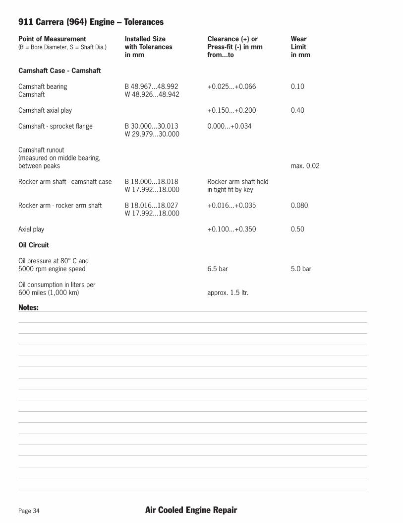
Camshaft Case - Camshaft
Camshaft bearing B 48.967...48.992 +0.025...+0.066 0.10Camshaft W 48.926...48.942
Camshaft axial play +0.150...+0.200 0.40
Camshaft - sprocket flange B 30.000...30.013 0.000...+0.034W 29.979...30.000
Camshaft runout(measured on middle bearing,between peaks max. 0.02
Rocker arm shaft - camshaft case B 18.000...18.018 Rocker arm shaft heldW 17.992...18.000 in tight fit by key
Rocker arm - rocker arm shaft B 18.016...18.027 +0.016...+0.035 0.080W 17.992...18.000
Axial play +0.100...+0.350 0.50
Oil Circuit
Oil pressure at 80° C and5000 rpm engine speed 6.5 bar 5.0 bar
Oil consumption in liters per600 miles (1,000 km) approx. 1.5 ltr.
Notes:

911 Carrera (964) Engine – Intermediate Shaft
Air Cooled Engine Repair Page 35
Intermediate Shaft/Drive Gear
Intermediate shaft and drive gear of 911 Carrera 2/4 (964) changed from the previous 911 Carrera 3.2 I and are paired andmay only be replaced together. Check the crankcase identification.
Intermediate Shaft/Drive Gear Installation – 911 Carrera 3.2 I Pre-1989
Identification (0 or 1) is die-stamped in the left crankcase below the alternatortake-up.
Gear wheels and crankcase may be paired with each other only as shown inthe table below.
Crankcase and Gear Pairing – 911 Carrera 3.2 I Pre-1989
Notes:

Page 36 Air Cooled Engine Repair
911 Carrera (964) Engine – Connecting Rods
Specifications and Differences of Connecting Rods Since 1964
Type 2.0 l 2.2 l 2.4 l 3.0 SC 3.3 l Turbo911 Carrera
Distance 911 Carrera 2/4
A 130 1 127.80 127.80 127.00-0.05 -0.05 -0.05
b 26.00 1 26.00 25.00 25.00-0.20 -0.20 -0.20 -0.50
c 21.80 1 23.70 21.70 21.70-0.1 +0.1 +0.1 +0.1
D 61.000 1 56.000 56.000 58.000+0.019 +0.019 +0.019 +0.019
G 22.020 1 22.020 22.020 23.020+0.013 +0.013 +0.013 +0.013
2 0.020... 0.020... 0.020... 0.020... 0.020...0.039 0.039 0.039 0.039 0.039max. max. max. max. max.0.055 0.055 0.055 0.055 0.055
Footnotes1 Same as 2.0 ltr. Engine, but stronger! Cannot be installed in 2.2 liter engine.2 Play between bush and piston pin

911 Carrera (964) Engine – Connecting Rods
Air Cooled Engine Repair Page 37
Connecting Rod Weights
Connecting rods are divided into weight groups. The final digits of the part number can be used to find a pertinent weightgroup. These final digits are inscribed in the shaft of connecting rods, which are supplied for replacements.
Weight Repair RepairMore than Up to Connecting Rod Connecting Rod Connecting RodGrams Grams Weight Group Part Number Code
615 624 3 964.103.020.53 53
624 633 4 964.103.020.54 54
633 642 5 964.103.020.55 55
642 651 6 964.103.020.56 56
651 660 7 964.103.020.57 57
660 669 8 964.103.020.58 58
669 678 9 964.103.020.59 59
678 687 10 964.103.020.60 60
687 696 11 964.103.020.61 61
Note:Connecting rods may only be installed in one engine when their difference in weight does not exceed 9 grams. Weight a com-plete connecting rod, but without bearing shells, to determine the weight group. Connecting rod codes for repair connectingrods are inscribed electrically.
Notes:

Page 38 Air Cooled Engine Repair
911 Carrera (964) Engine – Pistons & Cylinders
Piston & Cylinder Markings and Dimensions
For the 911 Carrera 2/4 (964), the cylinders are stamped onthe opposite side of the knock sensor bridge mounting. Thestamps include one mark for cylinder bore tolerance groupand one mark for cylinder height tolerance group.
Example in Figure 1 shows a cylinder with a cylinderheight group mark and a 1 bore tolerance group mark.
The cylinder bore measurement D (see Figure 2) is taken at apoint 56 mm down from the top of the cylinder. The height ismeasured at H, and the tolerance group stamps are in loca-tion T.
Note:Only cylinders with the came height group number (5 or 6)may be installed in the same cylinder bank of the engine.
The 911 Carrera 2/4 (964) pistons have the markings on the top (see Figure 3). The letter E is stamped in the center (facing Intake side); to the right is a internal Mahle desig-nation, and to the left, the tolerance group 0, 1, 2, or 3. Theweight group (– –, –, +, ++) is stamped next to the tolerancegroup mark.
Note:The weight group – – (double dash) may be applied verticallyor horizontally
Cylinder Tolerance Group Chart
Height (H) Cylinder Bore (D) Height Group Bore Group -0.020 +0.007 Stamp Stamp
82.750 100.000 0
82.750 100.007 1
82.750 100.014 2
82.750 100.021 3
82.770 100.000 0
82.770 100.007 1
82.770 100.014 2
82.770 100.021 3
Piston Tolerance Group Chart
Tolerance Group Cylinder Bore Piston DiameterStamp
0 100.000 - 100.007 99.970 - 99.9801 100.007 - 100.014 99.977 - 99.9872 100.014 - 100.021 99.984 - 99.9943 100.021 - 100.028 99.991 - 100.001
Figure 1
Figure 2
Figure 3

911 Carrera (964) Engine – Pistons
Air Cooled Engine Repair Page 39
Weight Groups of Pistons - 911 Carrera (3.2) and 911 Carrera 2/4 (964)
Mahle Pistons – Pistons are weighed with piston pin, piston rings, circlips.
Complete Piston Weight in GramsWeight Group Within Set Code
Engine Type 930.20/25/26 930.21 M 64.01/02
Standard production 618 ... 622 613 ... 617 644 ... 648 – –622 ... 626 617 ... 621 648 ... 652 –
Max. difference in 626 ... 630 621 ... 625 652 ... 656 +weight: 4 grams 630 ... 634 625 ... 629 656 ... 660 + +
Max. difference in 618 ... 626 613 ... 621 644 ... 652 – – or –weight for service: 626 ... 634 621 ... 629 652 ... 660 + or + +8 grams
KS Pistons (only 911 Carrera 3.2) – Pistons are weighed with piston pin, piston rings, circlips.
Complete Piston Weight in GramsWeight Group Within Set Code
Engine Type 930.21 USA
Standard production 654 ... 650 – –654 ... 658 –
Max. difference in 658 ... 662 +weight: 4 grams 662 ... 666 + +
Max. difference in 654 ... 662 – – or –weight for service: 662 ... 670 + or + +8 grams
Installing Instructions
1. Fundamentally only pistons of the same make and in the same pertinent weight group may be used within one engine.
2. Piston pins must always remain with the corresponding pistons, since piston weight is balanced out with the piston pins.
Notes:

Page 40 Air Cooled Engine Repair
911 Carrera (964) Engine – Cylinder Head
Installing Cylinder Heads
Tightening and torquing the cylinder head studs isdescribed below.
Cylinder Head Torquing Pattern
Instructions
1 - Apply a thin coat of Optimoly HT (copper paste) to thestuds.
2 - Install cylinder heads.3 - Apply a thin coat of Optimoly HD to the cylinder head
nuts and tighten as follows:
Stage 1 - Torque to 25 Nm (18 ftlb) as per the abovetorque sequence.
Stage 2 - 1 x 90° ± 2° following the torque pattern
90° Tightening Procedure Illustration
Note:Before the cylinder head nuts are tightened, the head boltsof the knock sensor bridge must be fastened, leave looseand do not tightened until after heads have been torqued.
Dimensions For Installing Valve Guides
Valve Guide Dimensions
Valve Guide Valve Guide OD* Bore Diameterin Cyl. Head
Standard 13.060 13.000 - 13.018Oversize 13.260 13.000 - 13.200
* Resurface outside diameter d of valve guide to appropri-ate bore diameter D considering negative allowance.
Distinguishing Features – The intake valve guide E has an additionalgroove (arrow)
Notes:

911 Carrera (964) Engine – Cylinder Head
Air Cooled Engine Repair Page 41
Cylinder Head Reconditioning
Cylinder heads may be reconditioned twice (0.1 ± 0.02mm may be machined off each time). Reconditioned headsmust be stamped with “- 10” or “- 20” on the intake portflange.
For uniform height, all the cylinder heads of one cylinderbank must be machined to the same size.
Original Cylinder Head Height is 84.48 ± 0.02 mm
Important:
It is not possible to machine the cylinder head mating sur-face with normal workshop equipment. The following pro-cedure applies to using a machine shop mill or lathe.
1. Clean cylinder head; media blast if necessary.
2. Mount cylinder in milling equipment level and mill 0.10± 0.02 mm off each of inner (II) and outer (III) surface.Cylinder heads may be reconditioned twice, taking off0.10 mm each time.
3. Slightly bevel edges of machined surfaces and mark(stamp) cylinder head “-10” or “-20” in area (I).
Valve Dimensions
Dimensions Intake Exhausta 49mm 42.5mmb 8.97mm 8.94...8.96mmc 110.1mm 109mmd 45° 45°
Checking Valve Spring Height
1. Install Special Tool P 10c together with the shimbelonging to a pertinent valve, spring retainer, springdisc and both collets.
2. Read distance “A” on Special Tool P 10c and correct, ifnecessary, by installing or removing shims.
Notes:

Page 42 Air Cooled Engine Repair
911 Carrera (964) Engine – Cylinder Head
Installed Length
Vehicle Type: 911 T 911 E 911 S
Engine Type:2.0 liters 901.01/03/05 901.06/09 901.02/10
Intake valve: 36 ± 0.3 mm 35 ± 0.3 mm 35.5 ± 0.3 mmExhaust valve: 36 ± 0.3 mm 35 ± 0.3 mm 34.5 ± 0.3 mm
Engine Type:2.2 - 2.4 liters 911.03/57/67 911.01/52/62 911.02/53/63
Intake valve: 35 ± 0.3 mm 34 ± 0.3 mm 35.5 ± 0.3 mmExhaust valve: 35 ± 0.3 mm 34 ± 0.3 mm 34.5 ± 0.3 mm
Vehicle Type: 911 911 S Carrera
Engine Type:2.7 liters 911.92/97 911.93/98 911.83
Intake valve: 35.0 ± 0.3 mm 35.0 ± 0.3 mm 35.5 ± 0.3 mmExhaust valve: 35.5 ± 0.3 mm 35.5 ± 0.3 mm 34.5 ± 0.3 mm
Vehicle Type: 911 Carrera 3.0 Turbo 3.0 Ltr.
Engine Type:2.7 - 3.0 liters 911.81/86 930.02/12 930.50/52
Intake valve: 35.0 ± 0.3 mm 34.5 ± 0.3 mm 33.5 ± 0.3 mmExhaust valve: 35.5 ± 0.3 mm 34.5 ± 0.3 mm 33.5 ± 0.3 mm
Vehicle Type: 911 SC/911 Carrera Turbo 3.3 911 Carrera 2/4 (964)
Engine Type:3.0 - 3.6 liters 930.03/13/20 930.60...68 M 64.01/02
Intake valve: 34.5 ± 0.3 mm 33.5 ± 0.3 mm 33.5 ± 0.3 mmExhaust valve: 34.5 ± 0.3 mm 33.5 ± 0.3 mm 34.5 ± 0.3 mm
Tightening Procedures for Cylinder Head of 911 Carrera
Cylinder head tightening procedures are changed from the old tightening torque method to the new torque angle tighteningmethod.The changed tightening procedures offer more safety against the loosening of cylinder head nuts with greater bolt tensileforce and more uniforem tightening of bolts among each other, in addition to less leakage on the cylinder head and cylinderbase.The modified procedures are for the time being only valid for the Service Sector (due to reasons of manufacturing) andconcern all Carrera engines, including Carrera 2 and 4 (not the 911 Turbo, which still uses a tightening torque of 32 Nm).
Procedures:
1. Coat threads of studs in the crankcase lightly with Optimoly HT.2. Mount cylinder heads.3. Install washers.

911 Carrera (964) Engine – Setting Timing
Air Cooled Engine Repair Page 43
From front edge of crankcase to face of intermediate shaft.
The intermediate shaft and camshaft must be pushed inaxial direction toward the flywheel prior to measuring, inorder to have the guide collar of the bearing in correct po-sition.
Example:
Distance A = 35.5 mm
Which means for cyl. 1 ... 3 sprocket: A + 98.07 = 35.5 + 98.07 = 133.57 mm
And for cyl. 4 ... 6 sprocket: A + 43.27 = 35.5 + 43.27 = 78.57 mm
Notes:
Adjusting Engine Timing – Since 1982
Timing Mark Locations
1. Turn crankshaft until mark “Z 1” on the pulley isprecisely aligned with the joint of the crankcase or dashmark on the blower housing.
2. Turn both camshafts to have the punch marks or code930 facing up. Engine will be in its basic position,valves of cylinder no. 1 in ignition TDC and valves ofcylinder no. 4 overlapping, after aligning mark “Z 1” onpulley with the joint and having punch marks of thecamshafts face up.
Design Dimensions For Chain Sprockets on Intermediate Shaft

Page 44 Air Cooled Engine Repair
911 Carrera (964) Engine – Setting Timing
3. Insert dowel pins.
4. Coat hexagon head bolts lightly with Optimoly HT.Screw on sprocket with hexagon head bolts finger tight.
5. Adjust valve clearance precisely (0.010 mm).
6. Mount dial gage with Special Tool P 207 on stud ofcamshaft case. Set dial gage to 0 (zero) with approx.10 mm preload on the spring retainer of the intakevalve in cylinder no. 1, with the valve closed.
7. Now turn the crankshaft clockwise by about one turnslowly from Z 1 (TDC), while observing the dial gage atthe same time. Turn so far until the mean value of theadjusting tolerances is reached. See Adjusting ValuesSection at end of “Setting Timing “ section.
8. Loosen mounting bolt on the left sprocket, removesprocket and pull out dowel pin with Tool P 212.
9. Turn crankshaft accordingly until mark Z 1 on the pulleyis precisely aligned with the joint of the crankcase ordash mark on the blower housing.
10. Reinstall dowel pin and tighten hexagon head boltlightly, while counterholding.
11. Turn crankshaft clockwise two more turns (720°) andrecheck the adjustment. The read value must now bewithin the specified tolerances for adjustment.
12. Tighten hexagon head bolt of the left camshaft to finaltorque of 120 Nm (12 kpm), while have a second per-son counterhold with Special Tool P 9191.
Adjusting Right Camshaft (Cyl. No. 4)
1. Adjust cylinder to ignition TDC (valves overlapping incylinder no. 1).
2. Repeat the adjusting procedures on cylinder no. 4 asdescribed in points 2 through 8.
Notes:

911 Carrera (964) Engine – Setting Timing
Air Cooled Engine Repair Page 45
Basic Adjustment – 911 Carrera 2/4 (964)
1. Turn crankshaft until mark on pulley is precisely alignedwith joint of crankcase or dash mark on blowerhousing.
2. Turn both camshafts until the punch marks face up.
3. Mount both auxiliary chain tensioners (Special Tool9401).
Notes:
Shows auxiliary chain tensioner on the left side.
The recess in the pressure piece should be just visible.
4. Adjust valve clearance precisely (0.10 mm)
Notes:

Page 46 Air Cooled Engine Repair
911 Carrera (964) Engine – Setting Timing
Adjusting Left Camshaft (Cyl. No. 1) – 911 Carrera2/4 (964)
5. Mount dial gage with Special Tool P 207 on stud of thecamshaft case. Set dial gage to 0 (zero) with approx.10 mm preload on the spring retainer of the intakevalve in cylinder no. 1.
6. Now turn the crankshaft clockwise by about one turnslowly from Z 1 (TDC) slowly, while observing the dialgage at the same time. Continue turning until the meanvalue of the specified tolerances for the adjustment isreached. See Adjusting Values Section at end of“Setting Timing “ section.
7. Loosen hexagon head bolt on left sprocket, removesprocket and pull out dowel pin with Tool P 212.
8. Turn crankshaft until mark Z 1 on pulley is preciselyaligned with joint of crankcase or dash mark on blowerhousing.
9. Reinstall dowel pin and tighten hexagon head boltlightly, while counterholding.
10. Turn crankshaft clockwise two more turns (720°) andrecheck the adjustment. The read value must now bewithin the specified tolerances.
11. Tighten hexagon head bolt of the left camshaft to finaltorque of 120 Nm (12 kpm), while have a second per-son counterhold with Special Tool P 9191.
Adjusting Right Camshaft (Cyl. No. 4) – 911 Carrera2/4 (964)
1. Set cylinder no. 4 to ignition TDC (valves overlapping incylinder no. 1).
2. Repeat adjusting procedures on cylinder no. 4 asdescribed in points 2 through 8.
Notes:

911 Carrera (964) Engine – Setting Timing
Air Cooled Engine Repair Page 47
Specifications for Cylinder Head Installation - 6 Cyl. Engines Since 1978 Models
Engine Type Model Year Tightening Method Timing Remarks
930.04...06 1978 ... 1983 Step 1: 10 Nm 0.9 ... 1.1 mm lift Camshaft No.930.10 Step 2: 32 Nm in overlapping right: 930 148 08930.15 TDC or 10(911 SC) left: 930 147 08
or 10
930.03/ 1978 ... 1983 Step 1: 10 Nm 1.4 ... 1.7 mm lift see above07...09 Step 2: 32 Nm in overlapping13/16/ TDC17/19(911 SC)
930.60 1978 ... 1989 Step 1: 10 Nm 0.65 ... 0.80 mm lift Camshaft No.up to 68 Step 2: 32 Nm in overlapping right: 930 142 00(911 Turbo) TDC or 03
left 930 143 00or 03
930.20/ 1984 ... 1989 Settling torque 1.1 ... 1.4 mm lift Camshaft No.21/25/26 15 Nm in overlapping right: 930 148 10(911 Carrera) Torque angle TDC left: 930 147 10
1 x 90° ± -2°
M 64.01/02 1989-94 Settling torque 1.16 ... 1.36 mm lift Camshaft No.15 Nm in overlapping right: 964 246 07
(911 Carrera 2/4 (964)) Torque angle TDC left: 964 247 091 x 90° ± 2°

Page 48 Air Cooled Engine Repair
911 Carrera (964) Engine
Notes: Notes:

911 Carrera (993) Engine
Air Cooled Engine Repair Page 49
Subject Page
General Information . . . . . . . . . . . . . . . . . . . . . . . . . . . . . . . . . . . . . . . . . . . . . . . . . . . . . . . .51
Crankcase . . . . . . . . . . . . . . . . . . . . . . . . . . . . . . . . . . . . . . . . . . . . . . . . . . . . . . . . . . . . . .53
Pistons . . . . . . . . . . . . . . . . . . . . . . . . . . . . . . . . . . . . . . . . . . . . . . . . . . . . . . . . . . . . . . . . .54
Cylinders . . . . . . . . . . . . . . . . . . . . . . . . . . . . . . . . . . . . . . . . . . . . . . . . . . . . . . . . . . . . . . . .55
Knock Bridge . . . . . . . . . . . . . . . . . . . . . . . . . . . . . . . . . . . . . . . . . . . . . . . . . . . . . . . . . . . .56
Cylinder Head . . . . . . . . . . . . . . . . . . . . . . . . . . . . . . . . . . . . . . . . . . . . . . . . . . . . . . . . . . . .56
Camshaft Housing . . . . . . . . . . . . . . . . . . . . . . . . . . . . . . . . . . . . . . . . . . . . . . . . . . . . . . . . .56
Valves . . . . . . . . . . . . . . . . . . . . . . . . . . . . . . . . . . . . . . . . . . . . . . . . . . . . . . . . . . . . . . . . . .57
Timing Gear . . . . . . . . . . . . . . . . . . . . . . . . . . . . . . . . . . . . . . . . . . . . . . . . . . . . . . . . . . . . .59
Auxiliary Air Pump . . . . . . . . . . . . . . . . . . . . . . . . . . . . . . . . . . . . . . . . . . . . . . . . . . . . . . . . .60
Engine Lubrication . . . . . . . . . . . . . . . . . . . . . . . . . . . . . . . . . . . . . . . . . . . . . . . . . . . . . . . . .61
Engine Cooling . . . . . . . . . . . . . . . . . . . . . . . . . . . . . . . . . . . . . . . . . . . . . . . . . . . . . . . . . . .63

Page 50 Air Cooled Engine Repair
911 Carrera (993) Engine
Notes: Notes:

911 Carrera (993) Engine
Air Cooled Engine Repair Page 51
Engine
General
M64.05/06 Engine
The engine for the new 911 Porsche Carrera is the logicalredevelopment of the previous Carrera engine. The aircooled, horizontally opposed light-alloy six-cylinder enginewas modified with the following development aims:
l Power increase of 10%l Reduction of fuel consumptionl Easier maintenancel Matching to the new rear axle
Engine Features
l Six-cylinder horizontally opposed enginel Light-alloy enginel Air cooledl Twin-valve engineeringl Hydraulic valve lash adjusterl Dry sump lubricationl Resonance charging with two-stage intake l DME with hot film air flow sensor l Twin ignition knock control l Engine idle charge regulation l Three way catalytic converter with metal carriers and l Lambda control
Important Innovations
The new M64.05/06 engines differentiate from the previ-ous M64.01/02 engines due to their lighter crank drivewithout vibration dampers as well as the hydraulic valvelash adjuster, the engine management system with hot filmsensor for mass air flow metering and the twin-pipeexhaust system.
Engine Type M64.05/06 Components
1 - Hot air blower2 - Switch for resonance flap control3 - Idle speed control4 - Mass air flow sensor5 - Air filter6 - Servo pump7 - Belt tension monitor8 - Ignition coils9 - Twin ignition distributor10 - Heating control temperature switch
Engine Type M64.05/06 Components
11 - Tank vent12 - Carbon canister connector13 - Power brake connector14 - NTC 2 connector15 - Knock sensor 1 connector16 - Resistor for heating control17 - Connector for speed and reference mark sender18 - Secondary oil filter
USA Secondary Air Injection not shown

Page 52 Air Cooled Engine Repair
911 Carrera (993) Engine
Longitudinal Section of the Engine
Engine Type M64.05/06 Side View Cutout
Cross Section of the Engine
Engine Type M64.05/06 Front View Cutout
Notes:
Full-Load Curve of the M64.05/06 Engine
Engine Data
Displacement 3.6 l (Stroke 76.4mm x Bore 100mm)Rated Power 200 kW/270HPNominal RPM 6100 rpmMax. Torque 330 Nm @ 5000 rpmCompression Ratio 11.3 : 1Fuel 98 RON/88 MON (Premium unleaded)
Notes:

911 Carrera (993) Engine
Air Cooled Engine Repair Page 53
Crankcase
The split aluminum-silicon alloy crankcase as well as thecrankcase bolting arrangement were adopted without anychanges from the 911 Carrera (964) 2/4
Crankshaft
Increased Crankshaft Web Area
The bending and torsional stiffness of the eight-bearingcrankshaft was increased by increasing the crank web dia.from 7.9 mm to 9.4 mm (see arrow). In conjunction withthe reduction of the oscillating masses, this allowed thetorsional vibration dampers on the crankshaft to be omit-ted. The weight of crankshaft as an individual componentincreased from 14.4 kg to 15.4 kg, yet the total weight ofthe complete crankshaft assembly was reduced by 0.818kg.
Main Bearings
The crankshaft main bearings were adopted without anychanges from the 911 Carrera (964) 2/4 engine.
Belt Pulley
Crankshaft Belt Pulley
A belt pulley is mounted on the cylindrical (formerlyconical) end of the crankshaft. In place of the torsional vibration damper. This reduces the overall weight from anoriginal 1161 g to 429 g.
Connecting Rods
Connecting Rod Differences
The reduction in weight of the connecting rods from 632 gto 520 g was achieved by recalculating the designstrength and by reducing the big end width from 21.9 mmto 18.9 mm. There are 7 weighting classes offered for theafter sales service. Only con-rods with a weight deviationfrom each other of less than 6 g may be fitted within oneengine.

Page 54 Air Cooled Engine Repair
911 Carrera (993) Engine
Big End (Connecting Rod) Bearings
Connecting Rod Bearing Shells
As the width of the connecting rod big end has beenreduced, the big end bearings had to be adapted as well.
Big End (Connecting Rod) Bolts
Connecting Rod Bolt
Along with the new connecting rods, a new big end bolt(grooved bolt) with a knurled twist lock surface under thebolt head was introduced. The tightening torque is 30 Nm+ 90° torque angle.
Notes:
Pistons
The pressed light alloy pistons have a diameter of100mm. The piston pin bore is off centered by 0.9mm.
Groove 1 – Taper faced ring (1.5mm).Groove 2 – Stepped taper faced ring (1.75.mm).Groove 3 – Double-level oil control ring with tubular spring
(2.0mm).
Piston Top
Care has to be taken on assembly to ensure that thecast-in identification letter “E” on the piston crown pointstowards the inlet side of the cylinder.
Piston Test Methods
The pistons are subdivided into four diameter tolerancegroups (0/1/2/3). The designation of the tolerance groupis located next to the letter “E”. The diameter is deter-mined at a height of 15 mm. In addition, the pistons aresubdivided into weight groups ranging from - -to ++.

911 Carrera (993) Engine
Air Cooled Engine Repair Page 55
Pistons
Underside of Piston
The total weight of the piston has been reduced from 657g to 602 g by reducing the wall thickness of thebox-shaped piston skirt area and by using a shorter pistonpin (see left hand side).
Wrist Pin Snap Ring
Piston Pin Snap Ring
The wrist pin snap ring design prevents the ring from turn-ing in its groove.
Notes:
Cylinders
The cylinders have a bore diameter (D) of 100 mm and aremade of high-temperature resistant light alloy. The boresurface coating (Nikasil) is applied galvanically. In order tocompensate for the differing temperatures across theheight of the cylinder and to maintain a constant runningclearance, the bore is machined with a slight taper.
As before, the cylinders are subdivided into two groups forthe length tolerances and four diameter tolerances. Thetolerance groups are stamped into the cylinder base (T).
Notes:

Page 56 Air Cooled Engine Repair
911 Carrera (993) Engine
Knock Sensor Bridge
The lugs cast on the cylinders are used for fitting of oneknock bridge (arrow) for each row of cylinders that is usedto accommodate a knock sensor. Observe the followingassembly procedure:
Knock Sensor Bridge Location
l Pre-assemble cylinders 1 ... 3 or 4 ... 6.l Fit the knock bridge and screw in the three M6 fastening
bolts.l Install the cylinder heads and tighten them down.
Note: Never tighten knock bridge until the cylinderheads are torqued down.
l Tighten the M6 bolts of the knock bridge, to a tighteningtorque 10 Nm.
Cylinder Head
The inlet port dia. has been increased from 41.5 mm to43 mm. A ceramic port liner is fitted into the outlet portsof the cylinder head. The port liner provides for a tempera-ture drop of approx. 400º C at the cylinder head. A furtherpositive effect of the port liner is that cooling of the
exhaust gas is reduced and that the actual temperatureavailable for heating and for the catalytic converterremains higher. Socket head bolts have replaced the studsin the cylinder head used for fitting of the camshaft hous-ing.
Cylinder Head
In order to obtain the best possible cooling of the cylinderhead. The cooling fins were designed for maximum cool-ing surface area, the cooling air volume was optimized byreducing flow resistance with the use of thinner coolingfins, and the cylinder head nuts and spark plug connectorswere thinned down further.
Valve Train
The camshafts are driven via two duplex roller chains bythe intermediate shaft, which rotates, at half the crank-shaft speed. The chains are guided by tensioning andguide rails made of plastic with a sprayed-on slideway lin-ing. Chain tensioners; integrated into the oil circuit of theengine are used to tension the chains and to dampen thechain oscillations.
Notes:
911 Carrera (993) Engine
Air Cooled Engine Repair Page 57
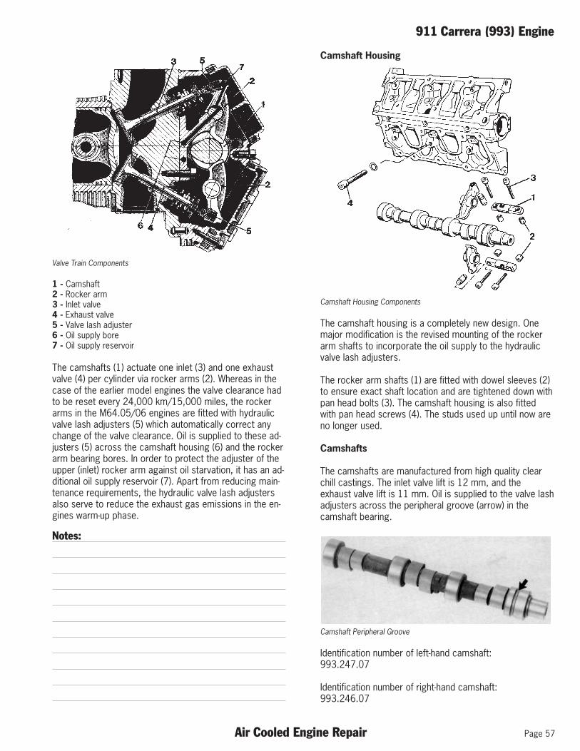
Valve Train Components
1 - Camshaft2 - Rocker arm3 - Inlet valve4 - Exhaust valve5 - Valve lash adjuster6 - Oil supply bore7 - Oil supply reservoir
The camshafts (1) actuate one inlet (3) and one exhaustvalve (4) per cylinder via rocker arms (2). Whereas in thecase of the earlier model engines the valve clearance hadto be reset every 24,000 km/15,000 miles, the rockerarms in the M64.05/06 engines are fitted with hydraulicvalve lash adjusters (5) which automatically correct anychange of the valve clearance. Oil is supplied to these ad-justers (5) across the camshaft housing (6) and the rockerarm bearing bores. In order to protect the adjuster of theupper (inlet) rocker arm against oil starvation, it has an ad-ditional oil supply reservoir (7). Apart from reducing main-tenance requirements, the hydraulic valve lash adjustersalso serve to reduce the exhaust gas emissions in the en-gines warm-up phase.
Notes:
Camshaft Housing
Camshaft Housing Components
The camshaft housing is a completely new design. Onemajor modification is the revised mounting of the rockerarm shafts to incorporate the oil supply to the hydraulicvalve lash adjusters.
The rocker arm shafts (1) are fitted with dowel sleeves (2)to ensure exact shaft location and are tightened down withpan head bolts (3). The camshaft housing is also fittedwith pan head screws (4). The studs used up until now areno longer used.
Camshafts
The camshafts are manufactured from high quality clearchill castings. The inlet valve lift is 12 mm, and theexhaust valve lift is 11 mm. Oil is supplied to the valve lashadjusters across the peripheral groove (arrow) in thecamshaft bearing.
Camshaft Peripheral Groove
Identification number of left-hand camshaft:993.247.07
Identification number of right-hand camshaft:993.246.07

Page 58 Air Cooled Engine Repair
911 Carrera (993) Engine
Rocker Arm
Rocker Arm Additional Oil Reservoir
The two rocker arms made of clear chill casting (GGG70)are different for the inlet (1) and exhaust (2) valve gear.The inlet port rocker arm has an additional oil reservoir (arrow) sealed with a cover plate.
Hydraulic Valve Lash Adjuster
Hydraulic Valve Lash Adjuster Components
The hydraulic valve lash adjuster is inserted in the rockerarm. The reservoir chamber (1) is supplied with pres-surized engine oil. When the valve clearance is readjusted,the oil flows past the ball into the pressure chamber (2).The oil escapes slowly over a drain gap (3) in the cylinderwall in order to ensure correct closing of the valve.
Notes:
Valves
Intake and Exhaust Valves
As the valve stem diameter was reduced by 1 mm, theweight of both the inlet and exhaust valves was reducedby 10 g. The inlet valves are filled with sodium to provideadditional cooling of the valve head and to ensure a bettercylinder charge.
Valve Springs
Valve Spring Assembly
The linear coil design of the valve spring assembly pro-vides an increased closing and final force. The installationdirection is not important.

911 Carrera (993) Engine
Air Cooled Engine Repair Page 59
Valve Spring Retainer
Valve Spring Retainer
The valve stem seal, the valve keepers as well as the valvespring caps have been adapted to fit the 8 mm valve stemdiameter. In addition, the weight of the valve head was re-duced by approx. 10 g.
Camshaft Housing Covers
The camshaft housing covers are made from glass fiberreinforced polyamide with inserted bushings fitted with aform seal. M6 bolts are used for fitting the housing cover.Tightening torque 10 Nm.
Notes:
Timing Gear
Setting the Timing
Setting the timing has been greatly simplified compared toprevious engines. A slot is machined in each camshaft asa timing reference to allow both camshafts to be locked ina specified position with special tools P 9551 and P 9552.
Special Tool 9551
Special Tool 9552
In addition, the crankshaft is located in the top dead cen-ter (TDC position using special tool P 9553).
Special Tool 9553

Page 60 Air Cooled Engine Repair
911 Carrera (993) Engine
Auxiliary Air Pump
Camshaft Housing
Additional bores for mounting the auxiliary air pump havebeen machined in the camshaft housing for USA vehicles.The air flows from port (A) acrocee the bores (B) to thecylinder heads.
Air Pump Air Injection Bore In Cylinder Head
The air is blown into the exhaust port through a transversepassage in the cylinder head.
Notes:
911 Carrera (993) Engine
Air Cooled Engine Repair Page 61
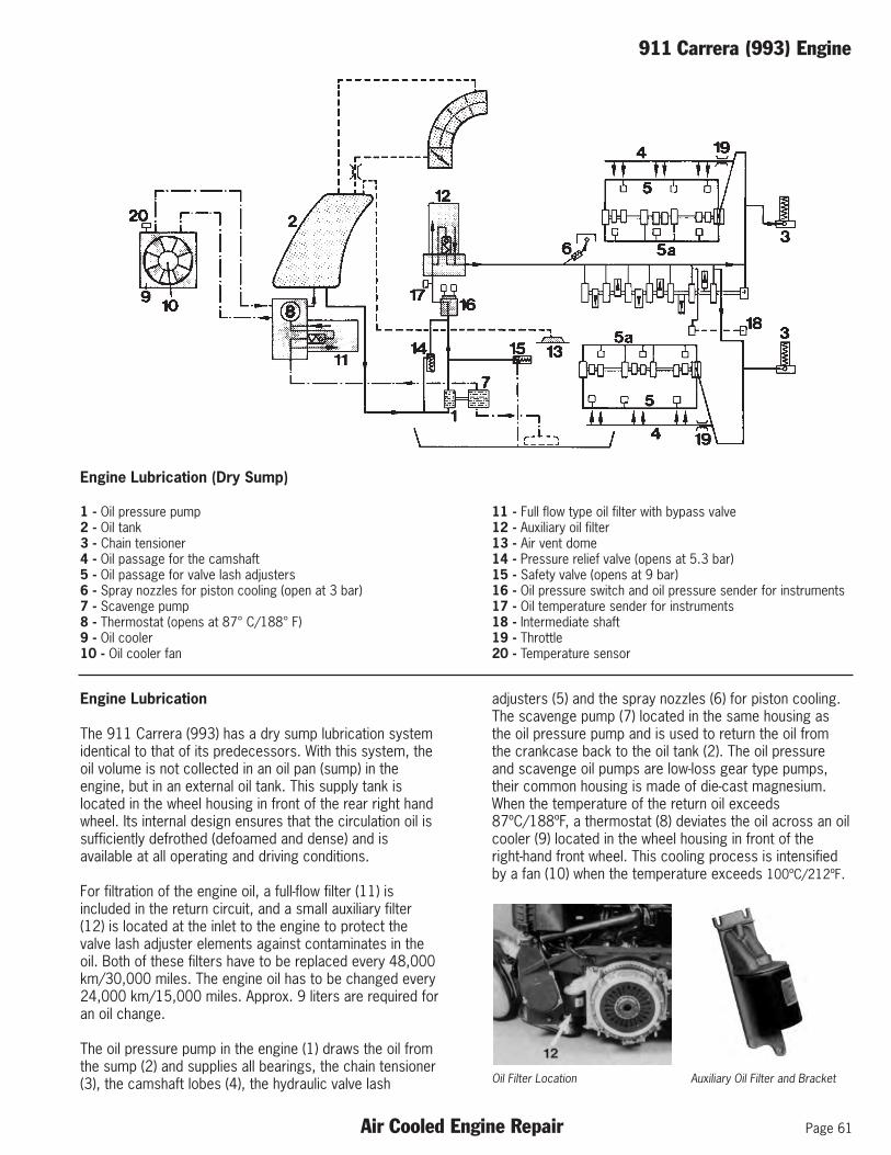
Engine Lubrication (Dry Sump)
1 - Oil pressure pump2 - Oil tank3 - Chain tensioner4 - Oil passage for the camshaft5 - Oil passage for valve lash adjusters6 - Spray nozzles for piston cooling (open at 3 bar)7 - Scavenge pump8 - Thermostat (opens at 87° C/188° F)9 - Oil cooler10 - Oil cooler fan
11 - Full flow type oil filter with bypass valve12 - Auxiliary oil filter13 - Air vent dome14 - Pressure relief valve (opens at 5.3 bar)15 - Safety valve (opens at 9 bar)16 - Oil pressure switch and oil pressure sender for instruments17 - Oil temperature sender for instruments18 - Intermediate shaft19 - Throttle20 - Temperature sensor
Engine Lubrication
The 911 Carrera (993) has a dry sump lubrication systemidentical to that of its predecessors. With this system, theoil volume is not collected in an oil pan (sump) in theengine, but in an external oil tank. This supply tank islocated in the wheel housing in front of the rear right handwheel. Its internal design ensures that the circulation oil issufficiently defrothed (defoamed and dense) and isavailable at all operating and driving conditions.
For filtration of the engine oil, a full-flow filter (11) isincluded in the return circuit, and a small auxiliary filter(12) is located at the inlet to the engine to protect thevalve lash adjuster elements against contaminates in theoil. Both of these filters have to be replaced every 48,000km/30,000 miles. The engine oil has to be changed every24,000 km/15,000 miles. Approx. 9 liters are required foran oil change.
The oil pressure pump in the engine (1) draws the oil fromthe sump (2) and supplies all bearings, the chain tensioner(3), the camshaft lobes (4), the hydraulic valve lash
adjusters (5) and the spray nozzles (6) for piston cooling.The scavenge pump (7) located in the same housing asthe oil pressure pump and is used to return the oil fromthe crankcase back to the oil tank (2). The oil pressureand scavenge oil pumps are low-loss gear type pumps,their common housing is made of die-cast magnesium.When the temperature of the return oil exceeds87ºC/188ºF, a thermostat (8) deviates the oil across an oilcooler (9) located in the wheel housing in front of theright-hand front wheel. This cooling process is intensifiedby a fan (10) when the temperature exceeds 100ºC/212ºF.
Oil Filter Location Auxiliary Oil Filter and Bracket

Page 62 Air Cooled Engine Repair
911 Carrera (993) Engine
Oil Supply to the Camshafts and Hydraulic ValveLash Adjusters
Oil Flow Through Cam Housing
The oil flows from the chain housing across a bridge to theinlet (A) of the camshaft housing. From the inlet, a portionof the oil is fed through the spray pipe (B) to lubricate thecams and rocker arms. The remaining oil flows to the rearcamshaft bearing, and across a peripheral groove (N) inthe camshaft to the distribution channels (C and D). A num-ber of these oil channels are blocked off with ball insertsand aluminum plugs.
The aluminum plugs (E) serve simultaneously for determin-ing the position of the spray pipe.
The remaining three camshaft bearings are supplied withlubrication oil over transverse bores (arrow) blocked offwith ball inserts.
The junction bores (arrows) that also connect to the distri-bution channels serve to lubricate the rocker arm shaftsand at the same time supply oil to the valve lash adjustersacross the rocker arms.
Notes:

911 Carrera (993) Engine
Air Cooled Engine Repair Page 63
Junction Bores in Cam Housing
Rocker Arm Shaft
Note: Rocker arm shafts are installed in one directiononly.
Engine Cooling
In line with its predecessors, the Porsche 911 Carrera(993) is fitted with an air-cooled engine. Air cooling is par-ticularly suitable for a compact drive unit mounted in therear of the vehicle. Apart from ease of maintenance, a par-ticular advantage of air cooling is the high temperature dif-ference between the external surface of the cylinders andthe ambient air that allows large amounts of heat energyto be transferred. The cooling air required is drawn in bythe engine cooling fan across the screen mounted in therear spoiler and then passes the finned cylinders, absorb-ing the heat to be dissipated in the process. Then the hotair is discharged towards the floorpan.
When designing the cylinders and the cylinder heads, suffi-cient cooling surface and the correct layout of the entirecooling area must be ensured. In addition, a sufficientlysized flow area for the cooling air and correct distributionto the cylinders and cylinder heads must be provided. Inorder to reduce heating of the cylinder head, the exhaustport is fitted with a ceramic port liner to act as a heat insu-lator. The fan has been designed and optimized for a highfeed rate at high efficiency and low noise levels. At highvehicle speeds, the fan is supported by the retractablerear spoiler that creates an increased pressure ahead ofthe spoiler due to the increased dynamic pressure ram effect.
Notes:

Page 64 Air Cooled Engine Repair
911 Carrera (993) Engine
Notes: Notes:

Conversion Charts
Air Cooled Engine Repair Page 65
Metric Conversion Formulas
INCH . . . . . . . . . . . . . X 25.4 = MMMM . . . . . . . . . . . . . . X .0394 = INCHMILE . . . . . . . . . . . . . X 1.609 = KILOMETER(KM)KM(KILOMETER). . . . . . . . . X .621 = MILEOUNCE . . . . . . . . . . . X 28.35 = GRAMGRAM . . . . . . . . . . . . X .0352 = OUNCEPOUND(lb) . . . . . . . . . . X .454 = KILOGRAM(kg)kg(KILOGRAM) . . . . . . . . . X 2.2046 = lb(POUND)CUBIC INCH . . . . . . . . X 16.387 = CUBIC CENTIMETER(cc)cc(CUBIC CENTIMETER) . . . . . X .061 = CUBIC INCHFOOTPOUND(ft lb) . . . . . X 1.3558 = NEWTON METER(Nm)Nm(NEWTON METER) . . . . . . X .7376 = ft lb(FOOT POUND) HORSEPOWER(SAE) . . . . X .746 = KILOWATT(Kw)HORSEPOWER(DIN) . . . . X .9861 = HORSEPOWER(SAE)Kw(KILOWATT). . . . . . . . . . X 1.34 = HORSEPOWER(SAE)HORSEPOWER(SAE) . . . X 1.014 = HORSEPOWER(DIN)MPG(MILES PER GALLON) . . . . X .4251 = Km/l(KILOMETER PER LITER)BAR . . . . . . . . . . . . . . X 14.5 = POUND/SQ. INCH(PSI)PSI(POUND SQUARE INCH) . . . . X .0689 = BARGALLON. . . . . . . . . . . X 3.7854 = LITERLITER. . . . . . . . . . . . . X .2642 = GALLONFAHRENHEIT . . . . . . . - 32÷1.8 = CELSIUSCELSIUS . . . . . . . . . . X 1.8+32 = FAHRENHEIT
TemperatureConversion

Page 66 Air Cooled Engine Repair
Conversion Charts
Notes: Notes:


Part Number - PNA P10 L01