A Finite Element Based Tool Chain for Structural Sizing of ... · ANSYS input file in the APDL...
11
A FINITE ELEMENT BASED TOOL CHAIN FOR STRUCTURAL SIZING OF TRANSPORT AIRCRAFT IN PRELIMINARY AIRCRAFT DESIGN J. Scherer*, D. Kohlgrüber*, F. Dorbath**, M. Sorour*** *German Aerospace Center (DLR), Institute of Structures and Design (BK), Pfaffenwaldring 38-40, 70569 Stuttgart, Germany **German Aerospace Center (DLR), Air Transportation Systems (LY) Blohmstraße 18, 21079 Hamburg, Germany ***University of Stuttgart, Institute of Aircraft Design (IFB), Pfaffenwaldring 31, 70569 Stuttgart, Germany [email protected], tel.: +49 (0) 711 6862-8082, fax: +49 (0) 711 6862-227 Abstract This paper introduces a fully parameterized finite element based tool chain for the structural sizing of transport aircraft. The chain consists of two model generators, a coupling module, a loads module for the computation of aerodynamic, fuel, landing gear and engine loads as well as a structural analysis and sizing algorithm. The finite element models of the wing and the empennage are created by the ELWIS multi-model generator, while the corresponding fuselage model is created using the TRAFUMO model generator. The structural coupling comprises the detailed modeling of all key structural elements of the center fuselage area including a keelbeam, bulkheads, sideboxes and lateral panels. The empennage coupling structure includes a reinforcement framework, reinforced frames and a mounting structure for the horizontal tail plane trim device. To establish suitability in preliminary aircraft design, a knowledge-based approach is chosen that enables a fully automatic model generation and coupling on a minimum set of required input parameters. As a central data format for input and output the DLR aircraft parameterization format CPACS is used. Therefore, the chain can be easily embedded in a wider MDA/MDO approach for overall preliminary aircraft design. Finally, first static sizing results are discussed and different validation methods for the static sizing algorithm are presented, including a comparison with a validated analytical method. 1. INTRODUCTION Preliminary aircraft design is a multidisciplinary task that involves calculations in a vast number of disciplines. To find an optimum configuration, the fast evaluation of a variety of trade studies is necessary. A high level of accuracy and reliability of the results is important, which usually limits the use of simple and fast computing methods. In general, two different classes of methods are used. Empirical methods are fast but limited especially in evaluating new configurations. Physics-based methods are more flexible but very time consuming if applied at a high level of detail. At the German Aerospace Center (DLR) multi-disciplinary tool chains for a fast evaluation of arbitrary aircraft designs with a high level of flexibility and accuracy have been established. For the assessment of the structural mass a tool chain based on parameterized finite element models is used to overcome current limitations of empirical models in evaluating new aircraft configurations. In this paper the modeling approach for the primary aircraft structure is introduced. Emphasis is given to the fuselage model and on the coupling of the fuselage with the wing and the empennage models, which are provided by a well-known model generator [1, 2]. In addition, the structural analysis and sizing process is described and first results are shown. Finally, a validation and calibration approach for the sizing tool is presented. 1.1. CPACS Input Format The presented tool chain uses the xml format based DLR aircraft parameterization format CPACS (Common Parametric Aircraft Configuration Scheme) as in- and output format. CPACS is under continuous development since 2005 and used as a common language for several disciplinary aircraft design tools at DLR and beyond [3]. The work on this standard was started in the DLR project TIVA (Technology Integration for the Virtual Aircraft) [4] and is continued in a variety of other DLR projects. Within CPACS all parameters needed for any analysis of an aircraft are defined, e.g. outer geometry, structural design, engines, load scenarios, missions, etc. The high flexibility of CPACS in combination with its hierarchical data structure allows the share of data of arbitrary levels of detail between different project partners. With the use of CPACS, it is possible to establish an overall aircraft design process that consists of a wide range of disciplinary tools available at different DLR institutes. The key advantage in using a common kind of language is that only two interfaces are needed for each tool instead of individual Deutscher Luft- und Raumfahrtkongress 2013 DocumentID: 301327 1
-
Upload
truongcong -
Category
Documents
-
view
245 -
download
1
Transcript of A Finite Element Based Tool Chain for Structural Sizing of ... · ANSYS input file in the APDL...

A FINITE ELEMENT BASED TOOL CHAIN FOR STRUCTURAL SIZING OF TRANSPORT AIRCRAFT IN PRELIMINARY AIRCRAFT DESIGN
J. Scherer*, D. Kohlgrüber*, F. Dorbath**, M. Sorour***
*German Aerospace Center (DLR), Institute of Structures and Design (BK),Pfaffenwaldring 38-40, 70569 Stuttgart, Germany
**German Aerospace Center (DLR), Air Transportation Systems (LY) Blohmstraße 18, 21079 Hamburg, Germany
***University of Stuttgart, Institute of Aircraft Design (IFB), Pfaffenwaldring 31, 70569 Stuttgart, Germany
[email protected], tel.: +49 (0) 711 6862-8082, fax: +49 (0) 711 6862-227
Abstract This paper introduces a fully parameterized finite element based tool chain for the structural sizing of transport aircraft. The chain consists of two model generators, a coupling module, a loads module for the computation of aerodynamic, fuel, landing gear and engine loads as well as a structural analysis and sizing algorithm. The finite element models of the wing and the empennage are created by the ELWIS multi-model generator, while the corresponding fuselage model is created using the TRAFUMO model generator. The structural coupling comprises the detailed modeling of all key structural elements of the center fuselage area including a keelbeam, bulkheads, sideboxes and lateral panels. The empennage coupling structure includes a reinforcement framework, reinforced frames and a mounting structure for the horizontal tail plane trim device. To establish suitability in preliminary aircraft design, a knowledge-based approach is chosen that enables a fully automatic model generation and coupling on a minimum set of required input parameters. As a central data format for input and output the DLR aircraft parameterization format CPACS is used. Therefore, the chain can be easily embedded in a wider MDA/MDO approach for overall preliminary aircraft design. Finally, first static sizing results are discussed and different validation methods for the static sizing algorithm are presented, including a comparison with a validated analytical method.
1. INTRODUCTION
Preliminary aircraft design is a multidisciplinary task that involves calculations in a vast number of disciplines. To find an optimum configuration, the fast evaluation of a variety of trade studies is necessary. A high level of accuracy and reliability of the results is important, which usually limits the use of simple and fast computing methods.
In general, two different classes of methods are used. Empirical methods are fast but limited especially in evaluating new configurations. Physics-based methods are more flexible but very time consuming if applied at a high level of detail.
At the German Aerospace Center (DLR) multi-disciplinary tool chains for a fast evaluation of arbitrary aircraft designs with a high level of flexibility and accuracy have been established. For the assessment of the structural mass a tool chain based on parameterized finite element models is used to overcome current limitations of empirical models in evaluating new aircraft configurations.
In this paper the modeling approach for the primary aircraft structure is introduced. Emphasis is given to the fuselage model and on the coupling of the fuselage with the wing and the empennage models, which are provided by a well-known model generator [1, 2]. In addition, the
structural analysis and sizing process is described and first results are shown. Finally, a validation and calibration approach for the sizing tool is presented.
1.1. CPACS Input Format
The presented tool chain uses the xml format based DLR aircraft parameterization format CPACS (Common Parametric Aircraft Configuration Scheme) as in- and output format.
CPACS is under continuous development since 2005 and used as a common language for several disciplinary aircraft design tools at DLR and beyond [3]. The work on this standard was started in the DLR project TIVA (Technology Integration for the Virtual Aircraft) [4] and is continued in a variety of other DLR projects.
Within CPACS all parameters needed for any analysis of an aircraft are defined, e.g. outer geometry, structural design, engines, load scenarios, missions, etc. The high flexibility of CPACS in combination with its hierarchical data structure allows the share of data of arbitrary levels of detail between different project partners. With the use of CPACS, it is possible to establish an overall aircraft design process that consists of a wide range of disciplinary tools available at different DLR institutes. The key advantage in using a common kind of language is that only two interfaces are needed for each tool instead of individual
Deutscher Luft- und Raumfahrtkongress 2013DocumentID: 301327
1

interfaces between all considered software tools [5].
After several years of internal development, the CPACS standard was made available to the public in 2012 and new developments are discussed at regular symposia on ‘Collaboration in Aircraft Design’. Currently, the version V2.1 of the CPACS standard is available for download [6]. This version is compatible to the work presented in this paper with the exception of the coupling of fuselage and empennage that shall be published in the next official CPACS release V2.2. In addition to the CPACS standard further support tools to process the CPACS data have been developed, such as the TIXI and TIGL libraries. For example the TIGL library (TIva, Geometry Library, [7]) includes specific functions to calculate coordinates of specific points on the fuselage and wing surface to be used during the model generation.
1.2. Tool Chain
The tool chain presented in this paper is composed of five different main modules: the two central model generators for the fuselage and wing-like components, the computation modules of the aerodynamic and secondary loads (fuel, engine and landing gear) [2], the coupling module and the structural analysis and sizing algorithm. A flow chart of the tool chain is presented in Fig. 1.
The fuselage and the wing models are generated independently and the loads on the undeformed lifting surfaces are computed. In the next step, the fuselage model is coupled with the wing and the empennage models. After that, the complete aircraft structure is analyzed and sized with respect to the computed aerodynamic and inertia loads acting on all components. After the sizing loop has converged, the outputs, e.g. updated element thickness, total mass, etc. are written to the CPACS data file and the tool chain stops.
Fig. 1. Tool chain overview
2. STRUCTURAL MODEL
In this paragraph the software tools used to create a fully coupled aircraft model will be described. This model consists of the main components fuselage, wing and empennage. For the application in a MDO process chain, these component models are coupled automatically using a CPACS based, fully parameterized center fuselage area as well as an empennage connection structure.
The fuselage model is created by the TRAFUMO (TRansport Aircraft FUselage MOdel) model generator and consists of the stiffened fuselage shell with discretely modeled stringers and frames plus cargo and pax floor structure, which are modeled using elastic beam elements.
The wing and empennage models generated by the ELWIS (Finite ELement WIng Structure) multi model generator consist of classical shell-based structures such as wing box, flaps, spoilers and ailerons and are extended by additional structures such as engine pylons, landing gears and the structural links that connect the movables and their parent structures [1].
The fully parameterized center fuselage area that connects the fuselage and the wing model includes all key structural components like a keelbeam, main frames, pressure bulkheads, and sideboxes. For the empennage connection structure reinforced frames and a stiffening framework are implemented.
2.1. Fuselage
The fuselage model is generated by the TRAFUMO model generator. Based on the CPACS definition, a complete FE model of the fuselage is generated including external loads and added masses in a fully automated process.
In a first step TRAFUMO reads in the CPACS file using a PYTHON based wrapper module, before it computes a geometry model of the fuselage and finally writes an ANSYS input file in the APDL (ANSYS Parametric Design Language) format that will be used in the ANSYS Pre-Processor PREP7 together with an in house developed toolbox called PROSHAPE, for the FE model generation. This toolbox extends the capabilities of the standard APDL commands.
The first part of the model generation is the computation of the so called geometry lofts of the fuselage hull and the floors in 3D-space. For this task TIGL library functions (see 1.1, [7]) are used extensively.
In the following step frames, stringers and floor structures are positioned on the fuselage geometry via cutting planes and their paths on the lofts are calculated using the TIGL functions [7]. The beam cross sections of all reinforcements are computed according to their CPACS definition, linked to the corresponding path definitions and finally extruded to generate appropriate beam elements with the correct cross sections.
For the static sizing purpose described in this paper TRAFUMO creates meshes in GFEM quality. On the
Deutscher Luft- und Raumfahrtkongress 2013
2

fuselage hull each fuselage bay between two adjacent frames and stringers forms one 4 node shell element. Frames, stringers and floor structures form one beam element between to geometrical crossing points. The bulkheads are modeled as a combination of shell elements for the pressure membranes and beam elements for the necessary reinforcements. In general, two options are available to model the complex center fuselage area. For the analysis of a pure fuselage model with a focus on a standard fuselage section, the center fuselage region may be simplified as a CPACS based rigid load introduction area. A more realistic definition of the center fuselage area can be modeled to couple the fuselage model and detailed wing models. In Fig. 2 the main components of the TRAFUMO fuselage model with the simplified center fuselage area are presented. The detailed center fuselage area is presented in paragraph 2.3.
As the complete geometry model is available during the model generation process, finer meshes can alternatively be derived for other purposes. For example, very fine models with element sizes of about 10 mm may be generated for subsequent crash simulations [8].
The next step comprises the allocation of the element properties. The specific element properties and materials are allocated to the elements according to their CPACS definitions. In the current version of TRAFUMO that is fully compatible to the CPACS V2.1 standard [6], the model generation is limited to isotropic materials (e.g. metal).
In addition to the mesh generation, TRAFUMO adds external loads as well as additional masses to the fuselage model as defined in the CPACS dataset. External loads are distributed over a certain rigid region that simplifies the representation of the load introduction structure. Additional masses are distributed over individually defined influence regions using RBE3 constraints that split up the total load according to the weighted stiffness of the structure.
Fig. 2. Structural components of the basic fuselage model generated using TRAFUMO
2.2. Wing and Empennage
The wing and empennage models are generated by the ELWIS multi model generator [1, 2]. ELWIS can generate the wing models for different analysis tools, ranging from beam models to finite element shell models or vortex-lattices models.
In the highly flexible CPACS definition all wing-like structures are defined as wings. These wing-like structures can be conventional wings, horizontal tail planes (HTPs), vertical tail planes (VTPs) or unconventional configurations such as box wings, strut braced wings or blended wing bodies. The ELWIS model generator is implemented being able to handle the whole CPACS flexibility. Additionally, ELWIS can include flaps (including flap tracks), ailerons and spoilers in the structural model (compare Fig. 3). However, as this study focuses on the primary structure of conventional configurations, only these functionalities are explained in the following. A more detailed description can be found in [1, 2].
The finite element wing model is generated by ELWIS in a fully automated process from the CPACS parameterization. The ELWIS model generator reads the CPACS file, builds an internal model of the wing and finally writes the ANSYS input file in the APDL (ANSYS Parametric Design Language) format.
The first step of the model generation is the computation of the wing’s planform. Therefore, all airfoils are placed in 3D-space. Next, the leading and trailing edge positions of all airfoils are analyzed and the planform is determined.
In the next step various different kind of ribs and spars are placed on the wing’s planform to generate the 2D structured mesh that is later used to compute the 3D structural finite element mesh. All spanwise element borders of the final structured mesh are defined by real and virtual ribs, while all chordwise element borders are defined by real and virtual spars. This means, that a spar respectively a rib has to be placed at each element border.
Spars that define the chordwise element segmentation are placed on the wing planform at the following positions: • Virtual spars at the leading and the trailing edge.• Real spars, as defined in CPACS.• Virtual spars at cut-outs of the upper or lower skin.• Virtual spars at changing material definitions on the
upper or lower skin• Virtual spars at the borders of intermediate structures
(filling structures between upper and lower skin, suchas honeycomb structures)
• Virtual spars due to the user defined mesh size.
Most of the aforementioned spars are not continuously defined from root to tip and can cross each other. Therefore, a smart function is implement that continues all spars to the root/tip and that merges different spars, if this leads to a better mesh quality.
After the spar placement, real and virtual ribs are placed on the wing planform for the spanwise segmentation. Ribs are placed for the same reasons as the spars, but in addition the following kinds of ribs are introduced:
Deutscher Luft- und Raumfahrtkongress 2013
3
• Ribs due to kinks of the wing planform.• Ribs due to material definition of the spars.• Ribs at the beginning, ending or at kinks of real spars.
Similar to the spars, also the ribs are continued to the leading and trailing edge, in order to get a structured mesh on the wing planform. Next, the mesh on the wing planform is interpolated on the wings outer geometry. This results in the keypoint positions of the upper and lower skin, which finishes the geometrical computations.
The allocation of the element properties is performed in the next step. Skins, ribs and spars are modeled as shell elements. Composite materials can either be modeled as multi-layered shell elements or as single-layered shell elements with equivalent material properties. Stringers are modeled in a smeared representation in an additional shell layer. Spar caps are modeled by beam elements having a rectangular cross section. The elements in front of and behind the wing box are also modeled, as they are used for the introduction of the aerodynamic loads. However, the element properties of these elements are modified in a way that they do not contribute to the wing stiffness (compare Fig. 7).
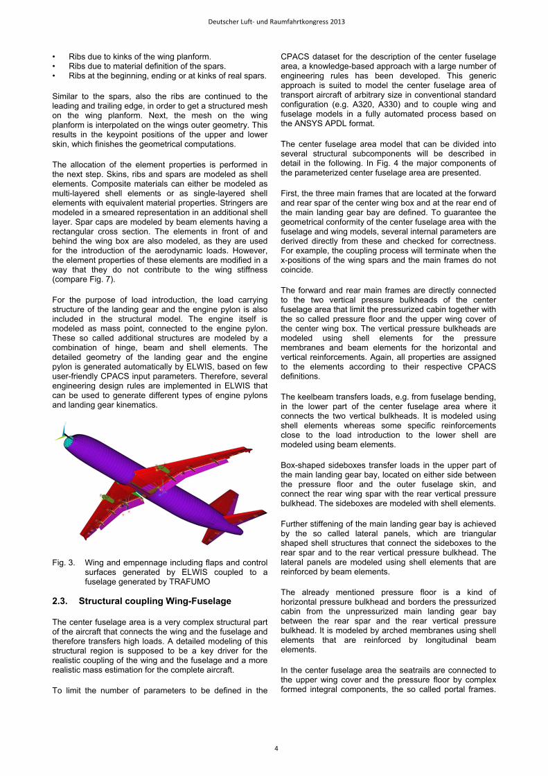
For the purpose of load introduction, the load carrying structure of the landing gear and the engine pylon is also included in the structural model. The engine itself is modeled as mass point, connected to the engine pylon. These so called additional structures are modeled by a combination of hinge, beam and shell elements. The detailed geometry of the landing gear and the engine pylon is generated automatically by ELWIS, based on few user-friendly CPACS input parameters. Therefore, several engineering design rules are implemented in ELWIS that can be used to generate different types of engine pylons and landing gear kinematics.
Fig. 3. Wing and empennage including flaps and control surfaces generated by ELWIS coupled to a fuselage generated by TRAFUMO
2.3. Structural coupling Wing-Fuselage
The center fuselage area is a very complex structural part of the aircraft that connects the wing and the fuselage and therefore transfers high loads. A detailed modeling of this structural region is supposed to be a key driver for the realistic coupling of the wing and the fuselage and a more realistic mass estimation for the complete aircraft.
To limit the number of parameters to be defined in the
CPACS dataset for the description of the center fuselage area, a knowledge-based approach with a large number of engineering rules has been developed. This generic approach is suited to model the center fuselage area of transport aircraft of arbitrary size in conventional standard configuration (e.g. A320, A330) and to couple wing and fuselage models in a fully automated process based on the ANSYS APDL format.
The center fuselage area model that can be divided into several structural subcomponents will be described in detail in the following. In Fig. 4 the major components of the parameterized center fuselage area are presented.
First, the three main frames that are located at the forward and rear spar of the center wing box and at the rear end of the main landing gear bay are defined. To guarantee the geometrical conformity of the center fuselage area with the fuselage and wing models, several internal parameters are derived directly from these and checked for correctness. For example, the coupling process will terminate when the x-positions of the wing spars and the main frames do not coincide.
The forward and rear main frames are directly connected to the two vertical pressure bulkheads of the center fuselage area that limit the pressurized cabin together with the so called pressure floor and the upper wing cover of the center wing box. The vertical pressure bulkheads are modeled using shell elements for the pressure membranes and beam elements for the horizontal and vertical reinforcements. Again, all properties are assigned to the elements according to their respective CPACS definitions.
The keelbeam transfers loads, e.g. from fuselage bending, in the lower part of the center fuselage area where it connects the two vertical bulkheads. It is modeled using shell elements whereas some specific reinforcements close to the load introduction to the lower shell are modeled using beam elements.
Box-shaped sideboxes transfer loads in the upper part of the main landing gear bay, located on either side between the pressure floor and the outer fuselage skin, and connect the rear wing spar with the rear vertical pressure bulkhead. The sideboxes are modeled with shell elements.
Further stiffening of the main landing gear bay is achieved by the so called lateral panels, which are triangular shaped shell structures that connect the sideboxes to the rear spar and to the rear vertical pressure bulkhead. The lateral panels are modeled using shell elements that are reinforced by beam elements.
The already mentioned pressure floor is a kind of horizontal pressure bulkhead and borders the pressurized cabin from the unpressurized main landing gear bay between the rear spar and the rear vertical pressure bulkhead. It is modeled by arched membranes using shell elements that are reinforced by longitudinal beam elements.
In the center fuselage area the seatrails are connected to the upper wing cover and the pressure floor by complex formed integral components, the so called portal frames.
Deutscher Luft- und Raumfahrtkongress 2013
4

As the distance between the pax floor and the wing upper cover differs significantly with the aircraft’s size (single aisle, twin aisle) no generic design could be established so far. As the structural relevance of the portal frames for the assessment of the whole aircraft is uncertain, they are currently simplified in the following way: the seatrails are connected to the pressure floor by vertical struts with arbitrary beam cross sections. Together with the corresponding longitudinal beam reinforcements of the pressure floor mentioned above, the corresponding seatrail and the vertical struts form a simplified representation of the portal frames. However, this model simplification requires a detailed assessment and potential model update in the future.
Although the fuselage model is automatically generated to share the geometry of the central part of the wing box, the actual structural coupling of the fuselage and the wing models is achieved by introducing ‘Constraint Equations’ and not by common nodes. One key advantage of this coupling is that the fuselage and the wing models may have individual mesh densities, which is often the case as models originate from different partners. Furthermore an exact geometrical coupling by common nodes is expected to be much more time consuming with less flexibility and robustness. To guarantee an efficient handling of the considered nodes for the coupling specific coupling components are generated during the modeling of the center fuselage area.
Fig. 4. Detailed center fuselage area main structural components displayed with the ANSYS /ESHAPE option, center wing box not shown
2.4. Structural coupling Empennage-Fuselage
As for the coupling of the wing and the fuselage a detailed modeling of the empennage coupling structure is important to improve the mass estimation of the complete aircraft. A generic knowledge-based approach comparable to the coupling of the wing necessitating only few user inputs defined in the CPACS data file has been developed for the coupling of the empennage and the fuselage, too. Using the APDL format this approach is suited to model the empennage connection structure within the fuselage of
arbitrary transport aircraft with a conventional empennage configuration (e.g. A320, A330) in a fully automated process.
In contrast to the coupling of the fuselage and the wing that uses a large number of coupling nodes and ‘Constraint Equations’, the coupling of the fuselage and the empennage considers only few discrete coupling nodes, that correspond to the attachment pins of the empennage as defined in CPACS [1].
For example, the HTP is attached to the fuselage at only three attachment pins that allow to model realistic trim deflections. Therefore hinge elements are defined at the two rear attachment pins that allow the adjustment of the HTP fin around the global y axis. The coupling of the VTP to the fuselage takes place at a defined number of attachment pins, very similar to the real aircraft structure. Similar to the coupling of the wing so called main frames are defined that transfer the loads from the HTP and VTP attachment pins into the fuselage skin.
The HTP connection requires a cutout in the fuselage outer surface. Therefore a part of the original fuselage structure is removed. The size of the cutout is determined automatically by the dimensions of the HTP’s center wing box and the maximum trim deflection angles defined in CPACS. To ensure the structural integrity of the fuselage hull, the cutout has to be reinforced. This is supported on the one hand by the reinforcement of the existing fuselage structure through redefinition of the original cross sections. On the other hand an additional reinforcement framework modeled using beam elements and additional plates modeled with shell elements is added to the fuselage. In general, all beam cross sections and shell thicknesses are user defined via CPACS. The reinforcement structure in the tail section of the fuselage, which is representative for several aircraft is shown in Fig. 5.
Some of the diagonal reinforcements that behave as purely axially loaded rods are modeled using beam elements, too, as bar elements can currently not be sized by S-BOT+. Therefore spherical joints are used to attach these beams to all other elements, which makes them to behave like bars.
The reinforcement framework and the cutout for the HTP integration are shown in Fig. 5. This kind of framework that transfers the loads around the cutout can be found in most aircraft with conventional trimmable HTP and is well suited for a generic approach.
For the VTP coupling an arbitrary number of attachment pins as well as the main frames to be used for the transfer of the VTP load are defined by the user. For a wide use of the generic approach two variants were implemented. The first one leads to a direct coupling of the attachment pins to a corresponding frame, while the second variant implies the position of the attachment pin to be between two adjacent frames and enables the coupling to both of them.
The main frames to which the VTP is attached to are heavily reinforced to ensure a smooth load transmission to the surrounding fuselage structure. The reinforcement structure is modeled using shell and beam elements comparable to the vertical bulkhead structure mentioned in
Deutscher Luft- und Raumfahrtkongress 2013
5
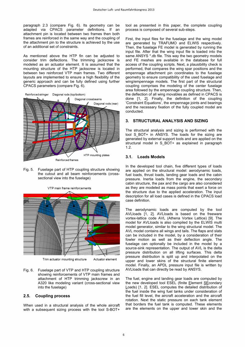
paragraph 2.3 (compare Fig. 6). Its geometry can be adapted via CPACS parameter definitions. If an attachment pin is located between two frames then both frames are reinforced in the same way and the coupling of the attachment pin to the structure is achieved by the use of an additional set of constraints.
As mentioned above the HTP fin can be adjusted to consider trim deflections. The trimming jackscrew is modeled as an actuator element. It is assumed that the mounting structure of the HTP jackscrew is located in between two reinforced VTP main frames. Two different layouts are implemented to ensure a high flexibility of the generic approach and can be fully defined using further CPACS parameters (compare Fig. 6).
Fig. 5. Fuselage part of HTP coupling structure showing the cutout and all beam reinforcements (cross-sectional view into the fuselage)
Fig. 6. Fuselage part of VTP and HTP coupling structure showing reinforcements of VTP main frames and attachment of HTP trimming jackscrew in an A320 like modeling variant (cross-sectional view into the fuselage)
2.5. Coupling process
When used in a structural analysis of the whole aircraft with a subsequent sizing process with the tool S-BOT+
tool as presented in this paper, the complete coupling process is composed of several sub-steps.
First, the input files for the fuselage and the wing model are generated by TRAFUMO and ELWIS respectively. Then, the fuselage FE model is generated by running the input file. After that the wing input file is loaded into the same ANSYS *.db file. This way the two geometry models and FE meshes are available in the database for full access of the coupling scripts. Next, a plausibility check is performed, that compares the wing spar positions and the empennage attachment pin coordinates to the fuselage geometry to ensure compatibility of the used fuselage and wing/empennage models. The first part of the structural coupling comprises the modeling of the center fuselage area followed by the empennage coupling structure. Then, the deflection of all wing movables as defined in CPACS is done [1, 2]. Finally, the definition of the coupling ‘Constraint Equations’, the empennage joints and bearings and the necessary fixation of the fully coupled model are conducted.
3. STRUCTURAL ANALYSIS AND SIZING
The structural analysis and sizing is performed with the tool S_BOT+ in ANSYS. The loads for the sizing are generated by external support tools and are applied on the structural model in S_BOT+ as explained in paragraph 1.2.
3.1. Loads Models
In the developed tool chain, five different types of loads are applied on the structural model: aerodynamic loads, fuel loads, thrust loads, landing gear loads and the cabin pressure. Inertia loads from the engine, the secondary cabin structure, the pax and the cargo are also considered as they are modeled as mass points that exert a force on the structure due to the applied acceleration. The input description for all load cases is defined in the CPACS load case definition.
The aerodynamic loads are computed by the tool AVLloads [1, 2]. AVLloads is based on the freeware vortex-lattice code AVL (Athena Vortex Lattice) [9]. The model for AVLloads is also compiled by the ELWIS multi model generator, similar to the wing structural model. The AVL model contains all wings and tails. The flaps and slats can be included in the model, by a consideration of their fowler motion as well as their deflection angle. The fuselage can optionally be included in the model by a source-sink representation. The output of AVL is the delta pressure distribution on all lifting surfaces. This delta pressure distribution is split up and interpolated on the upper and lower skins of the structural finite element model. Finally, an APDL pressure input file is written by AVLloads that can directly be read by ANSYS.
The fuel, engine and landing gear loads are computed by the new developed tool ESEL (finite Element SEcondary Loads) [1, 2]. ESEL computes the detailed distribution of the fuel inside the wing fuel tanks under consideration of the fuel fill level, the aircraft acceleration and the aircraft rotation. Next the static pressure on each tank element that borders the fuel tank is computed. These elements are the elements on the upper and lower skin and the
Deutscher Luft- und Raumfahrtkongress 2013
6

bordering ribs and spars. Finally, an APDL pressure input file is written that can be applied on the structural model.
The engine loads are applied as force vectors and are computed from the engine thrust level, the aircraft attitude and motion as well as the engine performance map.
Potential loads on the landing gear are directly computed from the CPACS load case description. The resulting forces are applied as force vectors on the axles of the landing gear.
The last load considered is the cabin pressure. It is defined in CPACS as a delta pressure value. The cabin pressure is applied as constant pressure distribution on the pressurized part of the fuselage model.
3.2. Structural Sizing
The structural sizing with respect to strength and stability criteria is performed with the tool S_BOT+ [1, 2], that is implemented in the ANSYS internal programming language APDL.
The strength evaluation in S_BOT+ is based on fully stressed design principles, which is usually performed with ultimate loads. However, fatigue load cases can be considered by reduced material limits. S_BOT+ computes the thickness of isotropic shell structures iteratively by the equivalent stress criterion of von Mises [10]. Based on the actual von Mises stress and the material limit, defined in CPACS, a scaling factor is calculated for each element. A very similar approach has been implemented for the beam structures in the fuselage model, where the material thickness in the cross section is updated.
For anisotropic shell structures, the user can choose between the maximum stress criterion [11], the Puck [12] and Tsai-Wu [11] failure criterion. For multi-layered anisotropic shell structures, the most critical layer is used to compute the scaling factor of the whole shell laminate layup. This means, that the whole laminate is sized at once and not each layer individually. The material orientation of anisotropic shell structures is computed by aligning the representative layer of the laminate along the mean principal stress direction of all load cases. Again, the whole laminate is rotated and not each layer individually.
Besides the strength criteria described above, potential stability failure is also considered. Shell structures are therefore sized to resist local compressive and shear buckling according to the handbook methods by Bruhn [13] that are implemented in S_BOT+. The critical buckling stress of the shell elements is computed and compared with the actual stress, which results in a scaling factor of the shell thickness.
The smeared stringer layer of the wing is dimensioned with respect to buckling constraints, too. The stringer pitch is computed so that the skin between two adjacent stringers does not buckle. The stringer material thickness is computed with respect to local buckling criteria while the whole stringer cross section is scaled with respect to Euler buckling of the skin-stringer panel. As the stringers are not included explicitly into the model, the computed stringer
properties are then translated into the equivalent material properties of the smeared stringer layer and applied on the model.
The cross-sectional area of individual beam elements is either sized with respect to the max stress or the von Mises stress criterion. Additionally, beams can be sized to resist Euler or Engesser buckling.
In a subsequent step, S-BOT+ checks whether the calculated material thicknesses of all elements are within the defined limits of minimum and maximum material thickness. Finally, the element properties within each sizing region are made equivalent, which also improves the convergence behavior and takes additional masses into account that are not modeled into the finite element model.
3.3. Static Analysis and Sizing Results
This paragraph contains exemplary analysis and S-BOT+ sizing results for a complete aircraft FE model. The evaluation of the results focusses on the fuselage and its detailed center fuselage region as well as the empennage coupling structure.
For the static sizing one exemplary load case has been selected, which is a 2.5 g maneuver load case. The loads were calculated by the tools AVLloads and ESEL within the ELWIS multi model generator (see paragraph 3.1). A cabin pressure difference was not applied as it is stabilizing the fuselage hull against buckling. Furthermore, engine loads were not applied as aerodynamic drag forces are not calculated by the tool AVLloads [1, 2] and therefore an equilibrium of forces in flight direction cannot be achieved. Landing gear loads were also not applied as the considered load case is an inflight load case.
When performing a complete aircraft sizing a weight and balance module is called in S_BOT+ once per iteration to compensate the change of the overall mass and the shift of the center of gravity due to the modification of the element properties during the sizing process. This is achieved by the definition of small additional masses that are linked to the cabin frames by constraints.
Although the load case shall be balanced and the mass changes within the iterative sizing shall be compensated by small extra masses, the complete aircraft model has to be fixed to suppress rigid body motions. Therefore, the model was fixed at the keelbeam close to the center of gravity defined in CPACS. Due to the corrections mentioned above the reaction forces at the fixation should be close to zero.
In the current model the shell and beam elements of the wing and the empennage center wing boxes as well as the shell elements of the fuselage were sized according to strength and stability criteria. The sizing of the beam elements of the fuselage, including all skin reinforcements, will be activated soon after further investigations.
Fig. 7 shows the von Mises stresses on the complete aircraft in an initial configuration with a standard skin thickness of 3 mm for the selected 2.5 g maneuver load case. The load level is quite low for large regions of the
Deutscher Luft- und Raumfahrtkongress 2013
7

fuselage, which indicates that the selected load case may not be the most critical one for sizing. However, the highest loads occur in the center fuselage part, namely the keelbeam, where the load level is notably above the yield stress limit of 240 MPa for the material used. Therefore, an increase of the skin thicknesses is expected in this region in a subsequent sizing process. In Fig. 8 the von Mises stresses on the tail section are displayed. The load level in the fuselage skin as well as in the HTP’s center wing box is significantly lower (around one order of magnitude) compared to the center fuselage region. Thus, a significant reduction of skin thicknesses is expected in this region in the following sizing process.
Fig. 9 shows the longitudinal stress distribution in the fuselage for the initial configuration and after the sizing process that takes 10 iterations to converge. It can be seen that the stress level in the upper skin increased up to the allowed maximum tensile stress. The stress level in the keelbeam decreased to the allowed maximum compressive stress, whereas the fuselage skin behind the keelbeam is altogether higher loaded than in the initial configuration.
Fig. 7. Von Mises stresses [Pa] on complete aircraft for a 2.5 g maneuver load case
Fig. 8. Von Mises stresses [Pa] on tail section for 2.5 g maneuver load case
The plot of the material utilization, the ratio the acting von Mises stress and the allowed limit stress in Fig. 10 shows that comparably few elements are sized to meet the limit stress. On the one hand this effect can be explained by the selected load case that applies a low load level in large parts of the model leading to the application of the minimum skin thickness criterion of 1.0 mm. On the other hand most of the fuselage and upper wing cover elements are sized due to the stability criteria (local skin buckling) with reduced limit stresses below the strength limit. The areas of high tensile load (lower wing cover), respectively high compression load (keelbeam) are sized due to the strength criteria and therefore have a high material utilization up to the value 1.
According to the first sizing results presented here, the correct functionality of the S-BOT+ sizing process for the sizing of complete aircraft models could be confirmed. Moreover, the importance of the use of a detailed center fuselage area and its impact to the sizing results is illustrated. However, the actual skin thickness results clearly indicate that the sizing with a single load case cannot lead to a proper thickness distribution and mass assessment, as this load case is only relevant for a small region of the fuselage.
Fig. 9. Longitudinal stresses [Pa] in fuselage skin before (top) and after (bottom) sizing with S-BOT+
Fig. 10. Material utilization (ratio of von Mises stress and limit stress) for complete aircraft after sizing process, only elements included in sizing shown
Deutscher Luft- und Raumfahrtkongress 2013
8

4. VALIDATION AND CALIBRATION
In general, all finite element models used in the preliminary aircraft design phase represent a simplification of the real aircraft geometry. These simplifications demand a validation and calibration process to ensure the comparability of the calculated masses to real aircraft masses. Two different approaches were used for the wing and the fuselage respectively that are depicted in this paragraph.
For the fuselage a step by step comparison to an analytical sizing tool was performed. This analytical tool is developed at the Institute of Aircraft Design (IFB) at the University of Stuttgart and is based on classical beam theory. The key advantage of the analytical tool is its ability to size simple fuselage structures in real time while the FE sizing approach with S-BOT+ is more time consuming but able to size more complex structures. The goal of the fuselage validation is to prove the correctness of the S-BOT+ sizing process for a simple fuselage structure before applying it to more complex structures that cannot be sized by the analytical tool.
For the wing model another validation approach was chosen. The final component masses of the sized structure are compared to masses of real aircraft components and finally calibration factors are determined to compute the realistic masses from the simulated masses.
4.1. Fuselage Validation Model
To prove the sizing results of S-BOT+ with the results of the extensively validated analytical tool, a common validation case has been defined and used by both tools in a multistep validation process.
The FE model for use in S-BOT+ represents a generic fuselage section with a constant cylindrical shape and a realistic frame and stringer distribution. This model comprises 14 fuselage bays with 13 circumferential frames and a total of 180 stringers, equally distributed with an angle increment of 2°, leading to a stringer pitch of close to 140 mm. The distance between two adjacent frames, that corresponds to the buckling length of the skin elements, is 600 mm. The model is clamped on one side whereas the loads are introduced on the opposite free side using constraints that form a rigid region (Fig. 11). For the comparison with the analytical tool the calculated stresses as well as the sized skin thicknesses are taken from a representative cross section were disturbing influences of both the clamping and the load introduction are assumed to be negligible (marked with red color in Fig. 11).
For the analytical tool based on beam theory a single cross section was loaded with the forces and moments acting in the relevant section of the FE model. For the modeling of the stringers the analytical tool uses a smeared representation with a constant ratio of skin to stringer cross-sectional area. This approach is common in preliminary aircraft design as it enables the engineer to calculate the stringer mass from the cross sectional area without having to know the detailed cross section’s shape. As the TRAFUMO fuselage modeling tool uses a discrete
stringer modeling approach, the S-BOT+ tool has been adapted to modify the stringer cross sections according to the defined ratio. Furthermore, solid rectangular stringer cross sections (low intrinsic moment of inertia) with their elastic center lying on the skin level were used to reduce possible differences resulting from the different stringer modeling approaches. The frame pitch is used to calculate the buckling factors for the stability analysis. However, the same fixed values were used for this comparison in both tools to reduce sources of error.
Fig. 11. Fuselage validation model with clamping, load introduction and representative cross section (marked with red color)
4.2. Fuselage Basic Validation
The fuselage basic validation comprises the examination of seven load cases with different combinations of a bending moment (My), a torsional moment (Mx) and a shear force (Qz) that are introduced at the load introduction section (Fig. 11). For each of the load cases the stress distributions calculated for a constant skin thickness by both tools were compared to each other. With 180 data points in the section (one at each element between two stringers) the resolution is assumed to be sufficient to detect potential local effects in the section.
For all of the seven load cases an almost perfect agreement of the calculated stresses was observed, which is the necessary basic requirement for the following sizing validation.
Furthermore, the basic validation with the FE model confirmed that the frame stiffness does not significantly influence the stress distribution in the defined load cases.
4.3. Fuselage Sizing Validation
The fuselage sizing validation comprises the examination of the same seven load cases as for the basic validation. For each load case the resulting skin thickness distribution from the S-BOT+ sizing process was compared against the results of the analytical tool at the representative cross section.
Deutscher Luft- und Raumfahrtkongress 2013
9

Considering the final skin thickness results extensive studies have been made including a proof whether the sizing criteria are met correctly, an examination of potential interaction of the considered sizing criteria and an examination of the influence of different damping factors in S-BOT+.
In general, a good agreement of the skin thickness results of S-BOT+ and the analytical tool could be observed for all of the seven load cases. Fig. 12 exemplarily shows the required skin thickness in the section calculated by both tools for a complex load case combining a shear force as well as a bending and torsional moment.
However, some constraints had to be considered for the sizing validation that will be explained in the following. As the analytical tool to date calculates the necessary skin thicknesses in a single step, only symmetrical load scenarios with respect to the y-axis and only one of the two sizing criteria (strength or stability) acting can be directly compared to the iterative S-BOT+ sizing process. For unsymmetrical load scenarios or scenarios were the both sizing criteria occur at the same time, only an iterative process can determine the correct skin thicknesses as the area moments of inertia and the shift of the elastic center of the representative cross section have to be taken into account. In these cases however, the results after the first iteration of the S-BOT+ sizing process can be compared to the results of the analytical tool.
Furthermore, restrictions of the finite elements have to be considered. For very low skin thicknesses the calculated stresses in the finite elements may get unrealistic. It is therefore essential to apply a minimum skin thickness in the S-BOT+ sizing process. That is why load scenarios that result in a skin thickness distribution were single skin elements theoretically are sized to zero thickness (e.g. a pure bending moment My) can only be compared partially to the results of the analytical tool as it does not allow for skin thickness restrictions in the current version.
Fig. 12. Exemplary skin thickness distributions over phi for a combined load case of Mx, My and Qz after sizing with S-BOT+ and the analytical tool
4.4. Calibration of the Wing Model
All finite element models that are used during preliminary aircraft design represent a simplification of the real aircraft geometry. These simplifications lead to a lower weight of the sized FE model, compared to the real aircraft structure. Therefore, calibration factors are used to compute the real mass from the modeled mass for the wing model.
The primary structure of the wing model is calibrated with respect to two reference aircraft, the Airbus A320 and the A340-200. The calibration factors as well as the resulting errors are shown in TAB 1. It can be seen, that the total error for the wing primary structure is extremely small. However, the small errors of the total primary structure result from counterbalancing errors of its subcomponents. The error of the skin and stringers computation is ± 2.5 %, while the error for the spars is ± 1.3 %. As both components have a comparable simple structural layout and clear structural load paths, small errors can be expected. The error at the rib computation has an absolute value of ± 10.3 %, which is comparably high. A detailed analysis of the masses of the ribs showed, that the mass of the ribs, close to the wing root, is too high. This effect is higher for the larger A340 wing than for the smaller A320 wing. The reason for that can be found in the modeling of the ribs with shell elements and the fact that each rib has a constant shell thickness. Therefore only one small high loaded element of the rib significantly increases the mass of the whole rib. At real aircraft, the ribs in the center wing box are often built up from several struts or have large cutouts to reduce the rib mass. Therefore, a more detailed modeling of the ribs might increase the accuracy.
TAB 1: Calibration factors and resulting errors of the wing model.
calibration factor [-]
A320 error [%]
A340 error [%]
Skin and stringer 1.671 2.5 -2.5 Spars 1.248 -1.3 1.3 Ribs 1.431 -10.3 10.3 Sum - 0.2 0.0
5. CONCLUSION AND OUTLOOK
This paper introduces a finite element based tool chain for the analysis and structural sizing of complete transport aircraft. The model generators for the creation of the wing-like models and the fuselage model are described and emphasis is put on the coupling modules developed to connect the fuselage, the wing and the empennage models in a realistic way. The structural coupling comprises the detailed modeling of all key structural elements in the center fuselage area including a keelbeam, bulkheads, sideboxes and lateral panels. The empennage coupling structure consists of a reinforcement framework, reinforced frames and a mounting structure for the horizontal tail plane trim device. The modeling and coupling process is knowledge-based and a wide range of engineering rules is implemented. Only few input parameters in the CPACS format are needed for model
Deutscher Luft- und Raumfahrtkongress 2013
10

generation. Therefore, this highly flexible and fully automated process is expected to be well suited for preliminary aircraft design. Finally, first static analysis and sizing results for a complete short to medium range aircraft are discussed and different validation approaches for the sizing tool are presented.
The next steps in the development of the presented tool chain are in first place a detailed analysis of the static sizing results for an appropriate selection of critical load cases. These load cases have to consider loading conditions from flight, ground, failure and emergency load cases. Due to expected findings a refining of the coupling structure and process may be necessary. Next, an improvement of the aerodynamic loads, e.g. the introduction of drag forces, seems to be essential to generate fully balanced load sets for the complete aircraft sizing. Moreover, a calibration of the complete aircraft based on the comparison of structural component masses to real aircraft masses is desirable. This step also implies the consideration of load cases with extended movables and ground load cases that act on the landing gear structure.
AKNOWLEDGEMENTS
The authors would like to thank Daniel Christmann from the University of Stuttgart for his support in developing and programming the coupling of empennage and fuselage and the continuation of the fuselage validation.
REFERENCES
[1] F. Dorbath, B. Nagel, V. Gollnick, Implementation of a Tool Chain for Extended Physics-Based Wing Mass Estimation in Early Design Stages, 71th Annual Conference of Society of Allied Weight Engineers (SAWE), Volume 72, No. 1, 2012.
[2] F. Dorbath, B. Nagel, V. Gollnick, Extended Physics-Based Wing Mass Estimation in Early Design Stages Applying Automated Model Generation, Journal of Aerospace Engineering, 2013, DOI: 10.1177/ 0954410013482657.
[3] B. Nagel et al., Communication in Aircraft Design: Can We Establish a Common Language?, 28th Congress of the International Council of the Aeronautical Sciences (ICAS), Brisbane, Australia, 2012.
[4] C. Liersch, M. Hepperle, A Distributed Toolbox for Multidisciplinary Preliminary Aircraft Design, CEAS Aeronautical Journal, Volume 2, Issue 1-4, pp 57-68, 2011, 10.1007/s13272-011-0024-6.
[5] D. Böhnke et al., An Integrated Methods for Determination of the Oswald Factor in a Multi-Fidelity Design Environment, 3rd CEAS Air & Space Conference, Venice, Italy, 2011.
[6] CPACS Homepage, [Online]. Available: http://code.google.com/p/cpacs/. [downloaded on 2013/08/19].
[7] TIGL Homepage, [Online]. Available: http://code.google.com/p/tigl/. [downloaded on 2013/08/19].
[8] D. Schwinn, J. Scherer, D. Kohlgrüber, K. Harbig, Development of a Multidisciplinary Process Chain for
the Preliminary Design of Aircraft Structures, NAFEMS World Congress, Salzburg, Austria, 2013.
[9] M. Drela, H. Youngren, AVL V-3.30 user primer, MIT Department of Aero & Astronautical Engineering, 2010.
[10] W. C. Young, R. G. Budynas, Roark’s Formulas for Stress and Strain, 7th Edition, New York, USA: McGraw-Hill Companies Inc., 2002.
[11] Z. Gürdal, R. T. Haftka, P. Hajela, Design and Optimization of Laminated Composite Materials, New York, USA: Wiley, 1999.
[12] A. Puck, Festigkeitsanalyse von Faser-Matrix-Laminaten - Modelle für die Praxis, Munich, Germany: Carl Hanser Verlag, 1996.
[13] E. F. Bruhn, Analysis & Design of Flight Vehicle Structures, Carmel, USA: Jacobs Publishing Inc., 1973.
Deutscher Luft- und Raumfahrtkongress 2013
11