16 - cdn.intechopen.comcdn.intechopen.com/pdfs/17813/InTech-Uwb_multifunction_antennas.pdf ·...
29
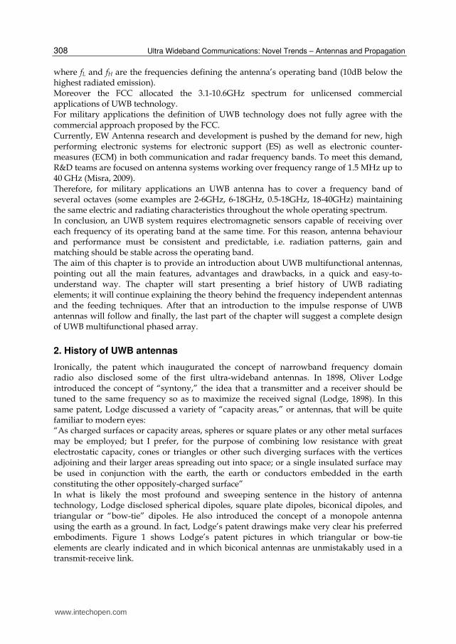
16 UWB Multifunction Antennas Paolo Baldonero, Roberto Flamini, Antonio Manna and Fabrizio Trotta Antenna Dept. Elettronica S.p.A. - Via Tiburtina Valeria Italy 1. Introduction In the last years Ultra-Wide Band technology has known an enormous success, both in military and civilian applications thanks to its undeniable advantages over standard systems. Nowadays the three main types of UWB applications are the following: 1. Applications involving radar, in which the signal penetrates nearby surfaces, allowing objects to be detected behind walls or other coverings. 2. Applications of communication: voice and data transmission using digital pulses, allowing a very low powered and relatively low cost signal to carry information at very high data rates within a restricted range. 3. Military applications, which comprehend the control of the e.m. scenario, preserving the use of electromagnetic spectrum for friendly use while denying its use to the enemy (that is the aim of the Electronic Warfare, EW 1 ). The use of large bandwidths offers multiple benefits including high date rates, robustness to propagation fading, accurate ranging and geolocation, superior obstacle penetration, resistance to jamming, interference rejection, and coexistence with narrow bandwidth systems. For the commercial systems, the Federal Communications Commission (FCC) in the United States established the rules for the operation of UWB devices. An UWB antenna is defined as a radiating element having a fractional bandwidth greater than 0.2 and a minimum bandwidth of 500 MHz. 2 0.2 H L H L f f BW f f and 500 H L f f Mhz (1) 1 Electronic warfare is defined as the art and the science of preserving the use of the electromagnetic spectrum for friendly use while denying its use to enemy (David Adamy). Electronic warfare has classically been divided into: (a) Electromagnetic Support Measures (ESM) – the receiving part of EW; (b) Electromagnetic Countermeasures (ECM) – jamming, chaff, and flares used to interfere with the operation of radars, military communication, and heat-seeking weapons; (c) Electromagnetic Counter- Countermeasures (ECCM) – measures taken in the design or operation of radars or communication systems to counter the effects of ECM. www.intechopen.com
Transcript of 16 - cdn.intechopen.comcdn.intechopen.com/pdfs/17813/InTech-Uwb_multifunction_antennas.pdf ·...
16
UWB Multifunction Antennas
Paolo Baldonero, Roberto Flamini, Antonio Manna and Fabrizio Trotta
Antenna Dept. Elettronica S.p.A. - Via Tiburtina Valeria Italy
1. Introduction
In the last years Ultra-Wide Band technology has known an enormous success, both in
military and civilian applications thanks to its undeniable advantages over standard
systems.
Nowadays the three main types of UWB applications are the following:
1. Applications involving radar, in which the signal penetrates nearby surfaces, allowing objects to be detected behind walls or other coverings.
2. Applications of communication: voice and data transmission using digital pulses, allowing a very low powered and relatively low cost signal to carry information at very high data rates within a restricted range.
3. Military applications, which comprehend the control of the e.m. scenario, preserving the use of electromagnetic spectrum for friendly use while denying its use to the enemy (that is the aim of the Electronic Warfare, EW1).
The use of large bandwidths offers multiple benefits including high date rates, robustness to
propagation fading, accurate ranging and geolocation, superior obstacle penetration,
resistance to jamming, interference rejection, and coexistence with narrow bandwidth
systems.
For the commercial systems, the Federal Communications Commission (FCC) in the United
States established the rules for the operation of UWB devices.
An UWB antenna is defined as a radiating element having a fractional bandwidth greater
than 0.2 and a minimum bandwidth of 500 MHz.
2 0.2H L
H L
f fBW
f f
and 500H L
f f Mhz (1)
1 Electronic warfare is defined as the art and the science of preserving the use of the electromagnetic
spectrum for friendly use while denying its use to enemy (David Adamy). Electronic warfare has classically been divided into: (a) Electromagnetic Support Measures (ESM) – the receiving part of EW; (b) Electromagnetic Countermeasures (ECM) – jamming, chaff, and flares used to interfere with the operation of radars, military communication, and heat-seeking weapons; (c) Electromagnetic Counter-Countermeasures (ECCM) – measures taken in the design or operation of radars or communication systems to counter the effects of ECM.
www.intechopen.com
Ultra Wideband Communications: Novel Trends – Antennas and Propagation
308
where fL and fH are the frequencies defining the antenna’s operating band (10dB below the highest radiated emission). Moreover the FCC allocated the 3.1-10.6GHz spectrum for unlicensed commercial applications of UWB technology. For military applications the definition of UWB technology does not fully agree with the commercial approach proposed by the FCC. Currently, EW Antenna research and development is pushed by the demand for new, high performing electronic systems for electronic support (ES) as well as electronic counter-measures (ECM) in both communication and radar frequency bands. To meet this demand, R&D teams are focused on antenna systems working over frequency range of 1.5 MHz up to 40 GHz (Misra, 2009). Therefore, for military applications an UWB antenna has to cover a frequency band of several octaves (some examples are 2-6GHz, 6-18GHz, 0.5-18GHz, 18-40GHz) maintaining the same electric and radiating characteristics throughout the whole operating spectrum. In conclusion, an UWB system requires electromagnetic sensors capable of receiving over each frequency of its operating band at the same time. For this reason, antenna behaviour and performance must be consistent and predictable, i.e. radiation patterns, gain and matching should be stable across the operating band. The aim of this chapter is to provide an introduction about UWB multifunctional antennas, pointing out all the main features, advantages and drawbacks, in a quick and easy-to-understand way. The chapter will start presenting a brief history of UWB radiating elements; it will continue explaining the theory behind the frequency independent antennas and the feeding techniques. After that an introduction to the impulse response of UWB antennas will follow and finally, the last part of the chapter will suggest a complete design of UWB multifunctional phased array.
2. History of UWB antennas
Ironically, the patent which inaugurated the concept of narrowband frequency domain radio also disclosed some of the first ultra-wideband antennas. In 1898, Oliver Lodge introduced the concept of “syntony,” the idea that a transmitter and a receiver should be tuned to the same frequency so as to maximize the received signal (Lodge, 1898). In this same patent, Lodge discussed a variety of “capacity areas,” or antennas, that will be quite familiar to modern eyes: “As charged surfaces or capacity areas, spheres or square plates or any other metal surfaces may be employed; but I prefer, for the purpose of combining low resistance with great electrostatic capacity, cones or triangles or other such diverging surfaces with the vertices adjoining and their larger areas spreading out into space; or a single insulated surface may be used in conjunction with the earth, the earth or conductors embedded in the earth constituting the other oppositely-charged surface” In what is likely the most profound and sweeping sentence in the history of antenna technology, Lodge disclosed spherical dipoles, square plate dipoles, biconical dipoles, and triangular or “bow-tie” dipoles. He also introduced the concept of a monopole antenna using the earth as a ground. In fact, Lodge’s patent drawings make very clear his preferred embodiments. Figure 1 shows Lodge’s patent pictures in which triangular or bow-tie elements are clearly indicated and in which biconical antennas are unmistakably used in a transmit-receive link.
www.intechopen.com

UWB Multifunction Antennas
309
Fig. 1. (left) Lodge preferred antennas consisting of triangular “capacity areas,” precursor of the “bow tie” antenna (right) Lodge’s biconical antennas
Around 1940, with the advent of research into television, interest in antennas that could handle the wider bandwidths associated with video signals increased. This renewed interest in wideband antennas led to the rediscovery of the biconical antenna and conical monopole by Carter in 1939 (see figure 2) (Carter, 1939).
Fig. 2. Carter’s biconical antenna (left) and conical monopole (right)
Carter improved Lodge’s original design by incorporating a tapered feed. Carter was among the first to take the key step of incorporating a broadband transition between feed line and radiating element. Perhaps the most prominent UWB antenna of the period was Lindenblad’s coaxial horn element (Lindenblad, 1939-1941). Lindenblad improved on the idea of a sleeve dipole element, adding a gradual impedance transformation to make it more broad banded. RCA chose Lindenblad’s element (figure 3 left) for experimental use in television transmission. RCA envisioned multiple channels being broadcast from the same central location, thus a wideband antenna was essential. For several years during the 1930’s, a turnstile array of Lindenblad’s coaxial horn elements graced the top of the Empire State Building in New York City where RCA located its experimental television transmitter. The figure 3 right displays a patent drawing of this array. The antennas at the top of the tower in this figure are folded dipoles used to transmit the audio portion of the television signal.
www.intechopen.com

Ultra Wideband Communications: Novel Trends – Antennas and Propagation
310
Fig. 3. Lindenblad’s element cross-section (left) and turnstile array for television transmission (right)
Other researchers pursued the idea of constructing antennas from coaxial transitions. Brillouin introduced coaxial horns, both omni-directional and directional (figure 4) (Brillouin, 1948).
Fig. 4. (left) omni-directional coaxial horn, (right) directional coaxial horn
By the year of 2000, an innovative UWB slot antenna was proposed by Barnes, as illustrated in figure 5. This slot antenna maintains a continuous taper design, therefore, with a suitable design of the slot taper, outstanding bandwidth and performance can be achieved. This UWB antenna was employed by The Time Domain Corporation as their first generation through-wall radar (Schantz & Barnes, 2001). From 1992, several microstrip, slot and planar monopole antennas with simple structure such as circular, elliptical or trapezoidal shapes have been proposed (Liang, et al., 2004; Lui, et al., 2005; Kim & Known, 2004; Seok,, et al., 2004; Ying & Zhang, 2004). Today the state of the art of UWB antennas focuses in these microstrip, slot and planar monopole antennas
www.intechopen.com
UWB Multifunction Antennas
311
with different matching techniques to improve the bandwidth ratio without loss of its radiation pattern properties.
Fig. 5. Barnes’s UWB slot antenna
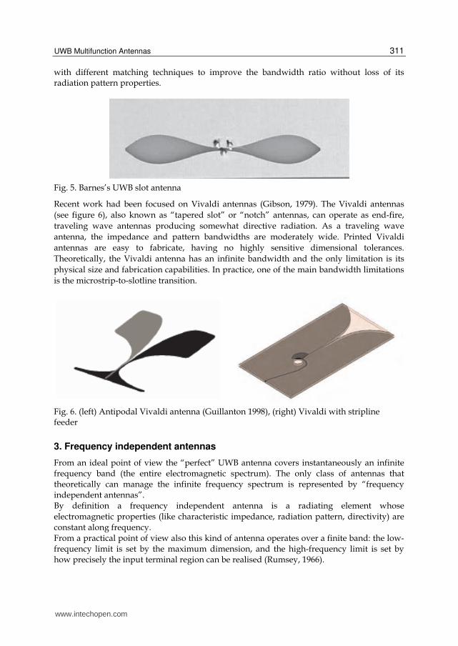
Recent work had been focused on Vivaldi antennas (Gibson, 1979). The Vivaldi antennas
(see figure 6), also known as “tapered slot” or “notch” antennas, can operate as end-fire,
traveling wave antennas producing somewhat directive radiation. As a traveling wave
antenna, the impedance and pattern bandwidths are moderately wide. Printed Vivaldi
antennas are easy to fabricate, having no highly sensitive dimensional tolerances.
Theoretically, the Vivaldi antenna has an infinite bandwidth and the only limitation is its
physical size and fabrication capabilities. In practice, one of the main bandwidth limitations
is the microstrip-to-slotline transition.
Fig. 6. (left) Antipodal Vivaldi antenna (Guillanton 1998), (right) Vivaldi with stripline feeder
3. Frequency independent antennas
From an ideal point of view the “perfect” UWB antenna covers instantaneously an infinite frequency band (the entire electromagnetic spectrum). The only class of antennas that theoretically can manage the infinite frequency spectrum is represented by “frequency independent antennas”. By definition a frequency independent antenna is a radiating element whose
electromagnetic properties (like characteristic impedance, radiation pattern, directivity) are
constant along frequency. From a practical point of view also this kind of antenna operates over a finite band: the low-frequency limit is set by the maximum dimension, and the high-frequency limit is set by how precisely the input terminal region can be realised (Rumsey, 1966).
www.intechopen.com
Ultra Wideband Communications: Novel Trends – Antennas and Propagation
312
All the studies made on this topic established that there are some principles to follow when designing a frequency independent antenna: 1. The scalability principle 2. The truncation principle 3. The self complementarity principle
3.1 Scalability principle This principle can be summarized as follows: an antenna can be defined as “scalable” if the current distribution on it does not change if antenna dimensions and operating wavelength change with the same ratio. In other words, decreasing the wavelength (increasing frequency), the model size decreases in the same proportion, and vice versa. Through this principle we can assure that a geometric structure, invariant to scaling changes, will be a frequency independent antenna. Structures that obey to this principle are called “auto-scaling” structures or continuously-scaled structures. V.H. Rumsey in 1966 looked for these particular configurations with the possibility to spatially fix the feeding terminals in order to keep them locked during the scale changes. In this way, a scale change of the geometric structure corresponds to its rotation. Putting these words in a mathematical language, we need to consider a polar coordinate system (r, θ, φ) and each structure within this system is identified by r (θ, φ). The auto-scalability condition is expressed by the following expression:
* ( , ) ( , ) K r r C (2)
Where K is the scaling factor and C is the rotation angle. This method leads to continuously scaled structures which satisfy the scalability principle. The equiangular spiral shape is a typical example of perfectly scaled structure (Dyson, 1959). A second class of antenna shapes satisfies this principle only at discrete frequency intervals. Such antennas are called “quasi frequency independent” and include “log-periodic” structures (the scaling law is logarithmic). This class of radiating elements shows a certain ripple on electrical performances between the frequency points of scaling. Sinuous and log-periodic dipoles belong to this latter class. A third class satisfies a different version of auto-scalability condition called “translation principle” that comes from a work by B. Stockbroeckx (Stockbroeckx , 2005). He tried to verify if the scalability principle could be satisfied also by structures not fully described by angles. In his work he looked for geometric shapes for which a scale variation does not imply a change in dimensions but a translation of the structure. Considering a rectangular coordinate system, for generic 3D structure we can describe the width as a function of height and length: x=x(y,z). The auto-scalability condition can be expressed as follows:
( , ) ( , )K x y z x y C z D (3)
and it is satisfied by all the structures that if scaled of a factor K, remain congruent to themselves translated of C respect to y and of D respect to z. It has been demonstrated that a geometrical structure with an exponential profile results independent from a geometrical scaling. Thus an antenna with an exponential shape (i.e. Vivaldi antenna) will show a frequency independent behaviour.
www.intechopen.com

UWB Multifunction Antennas
313
3.2 Truncation principle The discovery of structures invariant to changes in scale brings with it the assumption that these structures have infinite dimensions. Obviously this assumption makes not feasible the realization of such structures.
Therefore, in order to obtain a realizable antenna, we need to truncate its geometry trying to maintain the same radiating and electric characteristics of the infinite structure. So, following this approach, the radiating element has to satisfy the scalability principle and
the truncation principle.
There is an implicit fact included into the truncation principle: going away from the
excitation source up to the end of the antenna, the current flowing through the structure has
to decay up to nullify itself just before the end of the antenna. In other words, the travelling
wave needs to be attenuated after the radiating active region and before the end of the
structure. This attenuation should preferably be due to the radiation phenomenon, in fact, in
this way good efficiency and input impedance constant in frequency are assured.
This is a direct consequence of the fact that if the energy is mostly radiated, from a certain
point of the structure, the presence or absence of conductor is irrelevant.
Concluding we can say that constant radiating properties are obtained only if the active-
region dimension scale with wavelength and so, if the truncation effects are negligible, a
finite part of the auto-scaling antenna could yield a very wide operating band.
For the biconical antenna the angles’ principle is satisfied while the truncation one is not: the
total current along the infinite structure does not decrease with the distance from the
excitation point, so the truncation operation causes an important effect on radiating
characteristics. This happens because any finite portion, however large, will show end-
effects (like reflections from the ends) that produce variations of the radiation pattern.
Therefore the bandwidth cannot be increased at will by increasing the size.
3.3 Self-complementarity principle An additional characteristic that could be very helpful in the design of frequency
independent antennas is the self-complementarity feature. In more details, the self-
complementarity principle (Booker, 1946) affirms that for a planar self-complementary
structure (i.e. a planar shape identical to its own planar complement except for a rotation or
a mirroring) the input impedance is the real constant η2/4, where η is the intrinsic
impedance.
Then, it is clear that this principle could be satisfied also by non frequency independent
shapes and that a frequency independent structure could not be a self complementary
shape.
However the possibility to design a circuit that belongs to frequency independent antenna
family and at same time satisfies the self complementarity principle is of great interest. In
this way such radiator will have input impedance purely real and constant along the whole
frequency band. Consequently, the design of the feeding system will certainly require lower
effort respect to classic case of an UWB antenna with complex frequency dependent input
impedance. For this reason this useful principle is widely applied with spiral and sinuous radiating elements. However, in general, we need to keep in mind that self-complementary structures only guarantee constant input impedance, but not necessarily constant radiation characteristics.
www.intechopen.com
Ultra Wideband Communications: Novel Trends – Antennas and Propagation
314
4. Feeding systems for UWB antennas
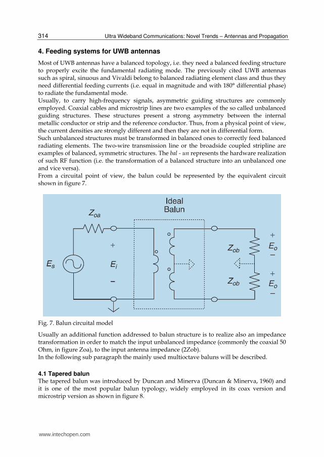
Most of UWB antennas have a balanced topology, i.e. they need a balanced feeding structure to properly excite the fundamental radiating mode. The previously cited UWB antennas such as spiral, sinuous and Vivaldi belong to balanced radiating element class and thus they need differential feeding currents (i.e. equal in magnitude and with 180° differential phase) to radiate the fundamental mode. Usually, to carry high-frequency signals, asymmetric guiding structures are commonly employed. Coaxial cables and microstrip lines are two examples of the so called unbalanced guiding structures. These structures present a strong asymmetry between the internal metallic conductor or strip and the reference conductor. Thus, from a physical point of view, the current densities are strongly different and then they are not in differential form. Such unbalanced structures must be transformed in balanced ones to correctly feed balanced radiating elements. The two-wire transmission line or the broadside coupled stripline are examples of balanced, symmetric structures. The bal - un represents the hardware realization of such RF function (i.e. the transformation of a balanced structure into an unbalanced one and vice versa). From a circuital point of view, the balun could be represented by the equivalent circuit shown in figure 7.
Fig. 7. Balun circuital model
Usually an additional function addressed to balun structure is to realize also an impedance transformation in order to match the input unbalanced impedance (commonly the coaxial 50 Ohm, in figure Zoa), to the input antenna impedance (2Zob). In the following sub paragraph the mainly used multioctave baluns will be described.
4.1 Tapered balun The tapered balun was introduced by Duncan and Minerva (Duncan & Minerva, 1960) and it is one of the most popular balun typology, widely employed in its coax version and microstrip version as shown in figure 8.
www.intechopen.com
UWB Multifunction Antennas
315
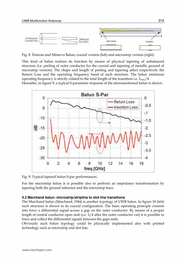
Fig. 8. Duncan and Minerva Balun; coaxial version (left) and microstrip version (right)
This kind of balun realizes its function by means of physical tapering of unbalanced structure (i.e. peeling of outer conductor for the coaxial and tapering of metallic ground of microstrip version). The shape and length of peeling and tapering affect respectively the Return Loss and the operating frequency band of such structure. The balun minimum operating frequency is strictly related to the total length of the transition i.e. λmax/4. Hereafter, in figure 9, a typical S-parameter response of the aforementioned balun is shown.
Fig. 9. Typical tapered balun S-par performances.
For the microstrip balun it is possible also to perform an impedance transformation by
tapering both the ground reference and the microstrip trace.
4.2 Marchand balun: microstrip/stripline to slot line transitions The Marchand balun (Marchand, 1944) is another typology of UWB balun. In figure 10 (left) such structure is shown in its coaxial configuration. The basic operating principle consists into force a differential signal across a gap on the outer conductor. By means of a proper length of central conductor open stub (i.e. λ/4 after the outer conductor cut) it is possible to force and collect the differential signals between the gaps ends. Obviously such balun typology could be physically implemented also with printed technology such as microstrip and slot line.
www.intechopen.com
Ultra Wideband Communications: Novel Trends – Antennas and Propagation
316
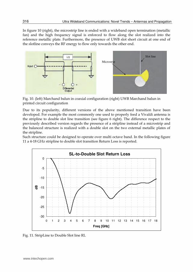
In figure 10 (right), the microstrip line is ended with a wideband open termination (metallic fan) and the high frequency signal is enforced to flow along the slot realized into the reference metallic plate. Furthermore, the presence of UWB slot short circuit at one end of the slotline conveys the RF energy to flow only towards the other end.
Microstrip
Slot line
Fig. 10. (left) Marchand balun in coaxial configuration (right) UWB Marchand balun in printed circuit configuration
Due to its popularity, different versions of the above mentioned transition have been developed. For example the most commonly one used to properly feed a Vivaldi antenna is the stripline to double slot line transition (see figure 6 right). The difference respect to the previously described version regards the presence of a stripline instead of a microstrip and the balanced structure is realized with a double slot on the two external metallic plates of the stripline. Such structure could be designed to operate over multi octave band. In the following figure 11 a 4-18 GHz stripline to double slot transition Return Loss is reported.
SL-to-Double Slot Return Loss
-30
-25
-20
-15
-10
-5
0
0 1 2 3 4 5 6 7 8 9 10 11 12 13 14 15 16 17 18
Freq [GHz]
dB
Fig. 11. StripLine to Double Slot line RL
www.intechopen.com

UWB Multifunction Antennas
317
4.3 Phelan Balun The balun introduced by H. R. Phelan (Phelan, 1969) is a particular realization of generalized Marchand balun also called “parallel-connected balun”. A parallel connected balun employs a two-wire or coaxial section of line in parallel with the balun junction to achieve a balanced output (see figure 12).
Fig. 12. Marchand balun
Here these structures will be referred to as resonant baluns due to the resonant line which is
inherent to their operation. The proposed Phelan balun is depicted in figure 13.
Fig. 13. Phelan balun
The central conductor of the coaxial input is connected to a solid “dummy” rod which maintains symmetry. The outer shield of output B is attached to the outer shield of the input cable, and the central conductor of output B is connected to the dummy rod. The outer shield of output A is soldered to the dummy rod and its central conductor is connected to the shield of the input cable. The balun junction is enclosed by a cavity which may be round or square. Note that this construction maintains symmetry both in the two ends of the cavity and at the feed point. In most applications, the outputs would be bent together to form a balanced double coaxial line.
www.intechopen.com
Ultra Wideband Communications: Novel Trends – Antennas and Propagation
318
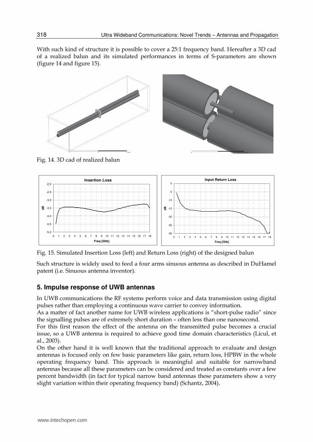
With such kind of structure it is possible to cover a 25:1 frequency band. Hereafter a 3D cad of a realized balun and its simulated performances in terms of S-parameters are shown (figure 14 and figure 15).
Fig. 14. 3D cad of realized balun
Insertion Loss
-5,0
-4,5
-4,0
-3,5
-3,0
-2,5
-2,0
0 1 2 3 4 5 6 7 8 9 10 11 12 13 14 15 16 17 18
Freq [GHz]
dB
Input Return Loss
-30
-25
-20
-15
-10
-5
0
0 1 2 3 4 5 6 7 8 9 10 11 12 13 14 15 16 17 18
Freq [GHz]
dB
Fig. 15. Simulated Insertion Loss (left) and Return Loss (right) of the designed balun
Such structure is widely used to feed a four arms sinuous antenna as described in DuHamel patent (i.e. Sinuous antenna inventor).
5. Impulse response of UWB antennas
In UWB communications the RF systems perform voice and data transmission using digital pulses rather than employing a continuous wave carrier to convey information. As a matter of fact another name for UWB wireless applications is “short-pulse radio” since the signalling pulses are of extremely short duration – often less than one nanosecond. For this first reason the effect of the antenna on the transmitted pulse becomes a crucial issue, so a UWB antenna is required to achieve good time domain characteristics (Licul, et al., 2003). On the other hand it is well known that the traditional approach to evaluate and design antennas is focused only on few basic parameters like gain, return loss, HPBW in the whole operating frequency band. This approach is meaningful and suitable for narrowband antennas because all these parameters can be considered and treated as constants over a few percent bandwidth (in fact for typical narrow band antennas these parameters show a very slight variation within their operating frequency band) (Schantz, 2004).
www.intechopen.com
UWB Multifunction Antennas
319
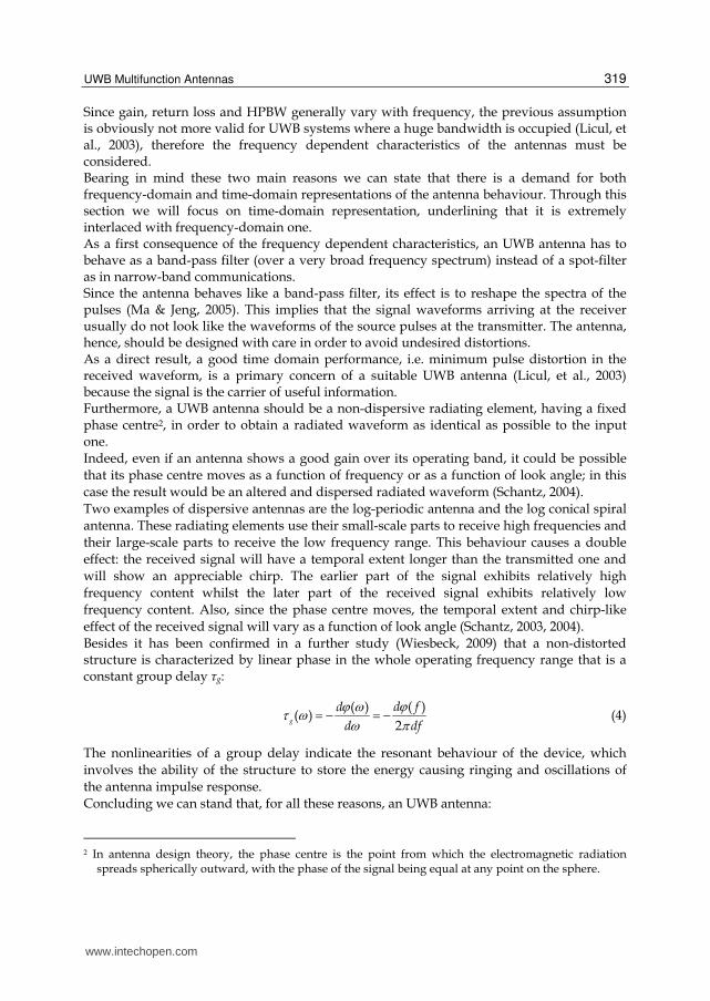
Since gain, return loss and HPBW generally vary with frequency, the previous assumption is obviously not more valid for UWB systems where a huge bandwidth is occupied (Licul, et al., 2003), therefore the frequency dependent characteristics of the antennas must be considered. Bearing in mind these two main reasons we can state that there is a demand for both frequency-domain and time-domain representations of the antenna behaviour. Through this section we will focus on time-domain representation, underlining that it is extremely interlaced with frequency-domain one. As a first consequence of the frequency dependent characteristics, an UWB antenna has to behave as a band-pass filter (over a very broad frequency spectrum) instead of a spot-filter as in narrow-band communications. Since the antenna behaves like a band-pass filter, its effect is to reshape the spectra of the pulses (Ma & Jeng, 2005). This implies that the signal waveforms arriving at the receiver usually do not look like the waveforms of the source pulses at the transmitter. The antenna, hence, should be designed with care in order to avoid undesired distortions. As a direct result, a good time domain performance, i.e. minimum pulse distortion in the received waveform, is a primary concern of a suitable UWB antenna (Licul, et al., 2003) because the signal is the carrier of useful information. Furthermore, a UWB antenna should be a non-dispersive radiating element, having a fixed phase centre2, in order to obtain a radiated waveform as identical as possible to the input one. Indeed, even if an antenna shows a good gain over its operating band, it could be possible
that its phase centre moves as a function of frequency or as a function of look angle; in this
case the result would be an altered and dispersed radiated waveform (Schantz, 2004).
Two examples of dispersive antennas are the log-periodic antenna and the log conical spiral
antenna. These radiating elements use their small-scale parts to receive high frequencies and
their large-scale parts to receive the low frequency range. This behaviour causes a double
effect: the received signal will have a temporal extent longer than the transmitted one and
will show an appreciable chirp. The earlier part of the signal exhibits relatively high
frequency content whilst the later part of the received signal exhibits relatively low
frequency content. Also, since the phase centre moves, the temporal extent and chirp-like
effect of the received signal will vary as a function of look angle (Schantz, 2003, 2004).
Besides it has been confirmed in a further study (Wiesbeck, 2009) that a non-distorted structure is characterized by linear phase in the whole operating frequency range that is a constant group delay τg:
( )( )
( )2
g
d fd
d df (4)
The nonlinearities of a group delay indicate the resonant behaviour of the device, which
involves the ability of the structure to store the energy causing ringing and oscillations of
the antenna impulse response.
Concluding we can stand that, for all these reasons, an UWB antenna:
2 In antenna design theory, the phase centre is the point from which the electromagnetic radiation
spreads spherically outward, with the phase of the signal being equal at any point on the sphere.
www.intechopen.com

Ultra Wideband Communications: Novel Trends – Antennas and Propagation
320
1. shall behave as a band-pass filter (instead of a spot-filter as in narrow-band systems) 2. shall not impact on the input signal shape 3. shall be a non-dispersive radiating element 4. shall show a fixed phase centre and a constant group delay.
Time response Antenna
Dipole
spherically capped Biconical
Log-periodic Dipole
equiangular Spiral
www.intechopen.com

UWB Multifunction Antennas
321
diamond Dipole
quad-ridged circular Horn
bi-Blade
Table 1. Time response of different antennas
Fig. 16. Time behaviour and spectral content of the monocycle Gaussian pulse
www.intechopen.com

Ultra Wideband Communications: Novel Trends – Antennas and Propagation
322
In a very interesting article (Ghosh, 2006) the authors analyzed the transient response of several well-known UWB antennas, and in Table 1 we list some of those results.
Each antenna was fed by a monocycle Gaussian pulse and the unit of time was a light meter
(lm), that is the time required by light to travel 1m ( 1 91 3.333 10lm c s ) In figure 16, the time behaviour and the spectral content of the monocycle pulse are shown.
6. UWB phased array
When the requirements about antenna gain, radiation pattern control and ERP (Effective
Radiated Power) are very demanding, it is not possible to choose a single element antenna
strategy. In this case an array approach is mandatory. Furthermore, in order to achieve the
array pattern control, the phase of the excitation signal of each single element must be
independently controllable. This is the so-called “phased array antenna strategy”.
If the operating bandwidth of the involved applications is extremely wide, UWB elements are needed for populating the selected array lattice. Clearly, depending on the application
(i.e. communications, radars or EW), the antenna specifications could be extremely different. In this paragraph we will present the design of an UWB phased array suitable for EW applications. In figure 17 the design flow chart of the adopted approach is shown. Obviously the first step consists in the definition of requirements (e.g. Operating Bandwidth, Gain, HPBW, Polarisation, mechanical constraints, etc...). Then the second phase concerns the element
selection. For our design we have employed the AHP (Analytical Hierarchy Process) methodology to select the best antenna candidate (Saaty, 1980). Then a first optimization loop occurs in order to improve the single radiating element performances in free space. In the following step the optimized element is merged in the selected array lattice and
simulated in infinite array structure. This latter approach allows us to reduce the simulation time and memory requirements exploiting the so called unit cell strategy (Pantano, et al., 2007). The unit cell consists in the single element of the array with suitable
periodic boundary conditions that replicate an infinite array structure. Obviously such
approach does not take into account edge and corner effects and will be meaningful for “electrically” small array. Due to mutual coupling phenomena, the antenna performances change. Therefore, a second optimization loop is needed to take into account the presence of surrounding elements. At the last point, depending on time and HW resources, the analysis
of the finite array is performed and the truncation and corner effects are then considered. Hereafter, the UWB double polarised planar phased array (DPPPA) design specifications are listed:
Operating Bandwidth 4-18GHz (goal 2-18 GHz)
Required scan angle ± 60° in both Azimuth and Elevation plane;
Typical radiating element HPBW 90° in both E and H plane;
VSWR less than 2.5:1 in the frequency band;
Grating lobes free @ 10.5 GHz;
Double linear polarisation; Two different radiating elements have been selected: the Vivaldi notch element, fed by strip-line, and the four arms Sinuous element, fed by ultra wide band double printed balun. According to the aforementioned design-flow chart, the design of the DPPPA has been divided into two phases:
www.intechopen.com

UWB Multifunction Antennas
323
Buy SmartDraw!- purchased copies print this
document without a watermark .
Visit www.smartdraw.com or call 1-800-768-3729.
Buy SmartDraw!- purchased copies print this
document without a watermark .
Visit www.smartdraw.com or call 1-800-768-3729.
Fig. 17. Design flow chart
www.intechopen.com

Ultra Wideband Communications: Novel Trends – Antennas and Propagation
324
1. the design and optimisation of the “isolated” element starting from the array specifications;
2. a further step of optimisation considering the “isolated” optimum element in infinite array configuration.
6.1 Vivaldi DPPPA Starting from the grating lobes free requirements, the selected array lattice is a regular square grid with 14.28 mm side (i.e. λ0/2 @ 10.5GHz). Consequently, the area dedicated to
each single element is 14.28 mm x 14.28 mm. In addition, due to the double linear polarization requirements each single array element
consists of two orthogonal Vivaldi antennas as depicted in figure 18. The selected Vivaldi
structure has been shown in figure 6 right (i.e. double Vivaldi with stripline feed).
Return Loss
-20
-18
-16
-14
-12
-10
-8
-6
-4
-2
0
2 3 4 5 6 7 8 9 10 11 12 13 14 15 16 17 18
Freq [GHz]
dB
Fig. 18. Array double circuit model and free space simulated Return Loss
It is noteworthy that in this way the two polarizations phase centre are not coincident and
their different location could be a disadvantage when a circular or slant 45° polarisation
must be realized.
According to the aforementioned design flow, the single Vivaldi couple has been optimised
in free space and then merged in the selected lattice to populate an infinite array.
In the following figures the simulation results after the infinite array optimisation loop are
reported. In particular, in figure 19 the 2D contour-plots of active Return Loss vs. Azimuth
and Elevation scan angle are respectively shown.
The active reflection coefficient is defined as the reflection seen in the antenna elements
when all elements are transmitting (active). If the antenna aperture scattering matrix is
denoted [S], the active reflections coefficients i are then defined as
1 11 12 1
2 21 22
1
1
2
...
... ...
... ... ... ... ... ...
... ...
j
N
j
j
N N NNN
S S S e
S S e
S S e
(5)
where N is the number of antenna elements and i is a scan dependent phase angle. From the shown results, two main characteristics could be highlighted:
www.intechopen.com
UWB Multifunction Antennas
325
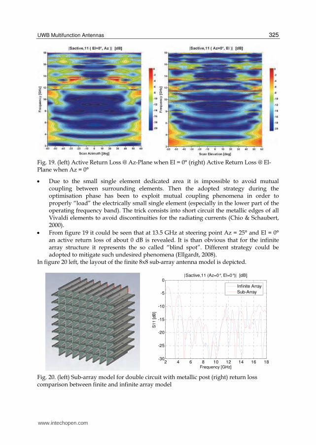
Fig. 19. (left) Active Return Loss @ Az-Plane when El = 0° (right) Active Return Loss @ El-Plane when Az = 0°
Due to the small single element dedicated area it is impossible to avoid mutual coupling between surrounding elements. Then the adopted strategy during the optimisation phase has been to exploit mutual coupling phenomena in order to properly “load” the electrically small single element (especially in the lower part of the operating frequency band). The trick consists into short circuit the metallic edges of all Vivaldi elements to avoid discontinuities for the radiating currents (Chio & Schaubert, 2000).
From figure 19 it could be seen that at 13.5 GHz at steering point Az = 25° and El = 0° an active return loss of about 0 dB is revealed. It is than obvious that for the infinite array structure it represents the so called “blind spot”. Different strategy could be adopted to mitigate such undesired phenomena (Ellgardt, 2008).
In figure 20 left, the layout of the finite 8x8 sub-array antenna model is depicted.
2 4 6 8 10 12 14 16 18-30
-25
-20
-15
-10
-5
0|Sactive,11 (Az=0°, El=0°)| [dB]
Frequency [GHz]
S11 [dB
]
Infinite Array
Sub-Array
Fig. 20. (left) Sub-array model for double circuit with metallic post (right) return loss comparison between finite and infinite array model
www.intechopen.com
Ultra Wideband Communications: Novel Trends – Antennas and Propagation
326
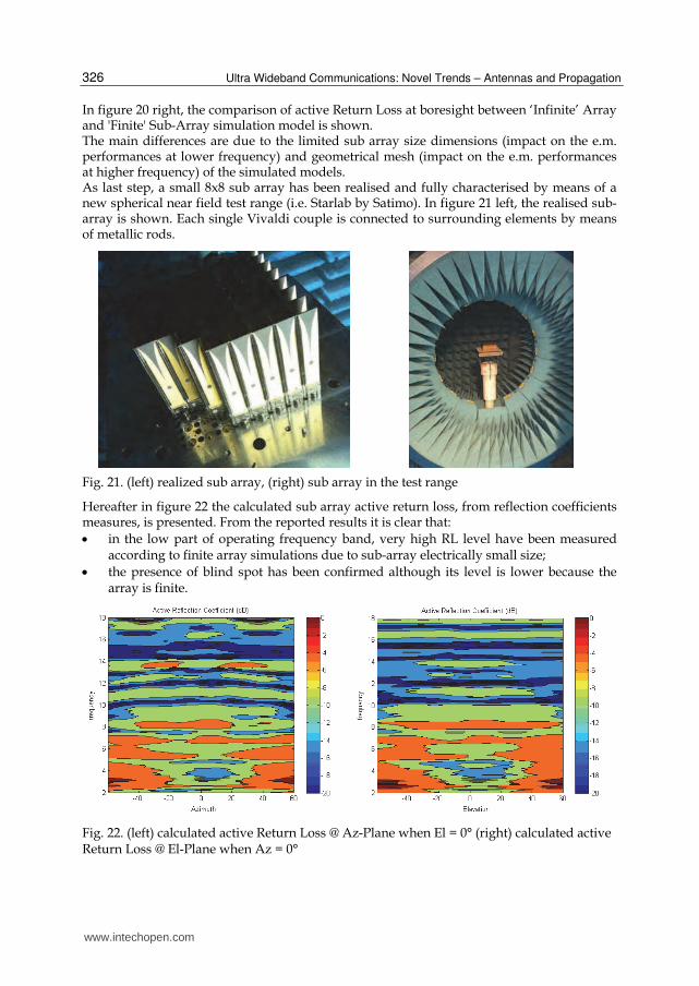
In figure 20 right, the comparison of active Return Loss at boresight between ‘Infinite’ Array and 'Finite' Sub-Array simulation model is shown. The main differences are due to the limited sub array size dimensions (impact on the e.m. performances at lower frequency) and geometrical mesh (impact on the e.m. performances at higher frequency) of the simulated models. As last step, a small 8x8 sub array has been realised and fully characterised by means of a new spherical near field test range (i.e. Starlab by Satimo). In figure 21 left, the realised sub-array is shown. Each single Vivaldi couple is connected to surrounding elements by means of metallic rods.
Fig. 21. (left) realized sub array, (right) sub array in the test range
Hereafter in figure 22 the calculated sub array active return loss, from reflection coefficients measures, is presented. From the reported results it is clear that:
in the low part of operating frequency band, very high RL level have been measured according to finite array simulations due to sub-array electrically small size;
the presence of blind spot has been confirmed although its level is lower because the array is finite.
Fig. 22. (left) calculated active Return Loss @ Az-Plane when El = 0° (right) calculated active Return Loss @ El-Plane when Az = 0°
www.intechopen.com

UWB Multifunction Antennas
327
Fig. 23. (left) simulated Sub-Array boresight gain (right) measured Sub-Array boresight gain
Fig. 24. (left) simulated Sub-Array gain for azimuth beam steering of +25° (right) measured Sub-Array gain for azimuth beam steering of +25°
In the previous figures the simulated and measured Far Field array performances at different steering point are shown. The figure 23 shows the gain at boresight, while the figure 24 shows the measured gain when the array steering point is 25° in the azimuth plane for elevation 0°. As it is possible to see, there is a good agreement between simulated and measured values. In figure 24 it is also noticeable that a gain drop occurs in correspondence of 13.5 GHz and 25° azimuth scan angle. Such behavior is in agreement with previous blind spot analysis. Indeed, if we go back to figure 19 and figure 22, we can retrieve that at the same frequency and scan angle the presence of a blind spot was detected. The following figure 25, figure 26 and figure 27, show the results of some measured pattern cuts at different frequencies and beam steering.
Sub-Array pattern @ 4 GHz
Sub-Array pattern @ 10 GHz
www.intechopen.com

Ultra Wideband Communications: Novel Trends – Antennas and Propagation
328
Sub-Array pattern @ 17 GHz
Sub-Array pattern @ 18 GHz
Fig. 25. Boresight Sub-Array patterns
Sub-Array pattern @ 6 GHz scan 30°
Sub-Array pattern @ 9 GHz scan 30°
Sub-Array pattern @ 12 GHz scan 30°
Sub-Array pattern @ 15 GHz scan 30°
Fig. 26. 30° beam steering Sub-Array patterns (azimuth cut @ elevation 0°)
www.intechopen.com
UWB Multifunction Antennas
329
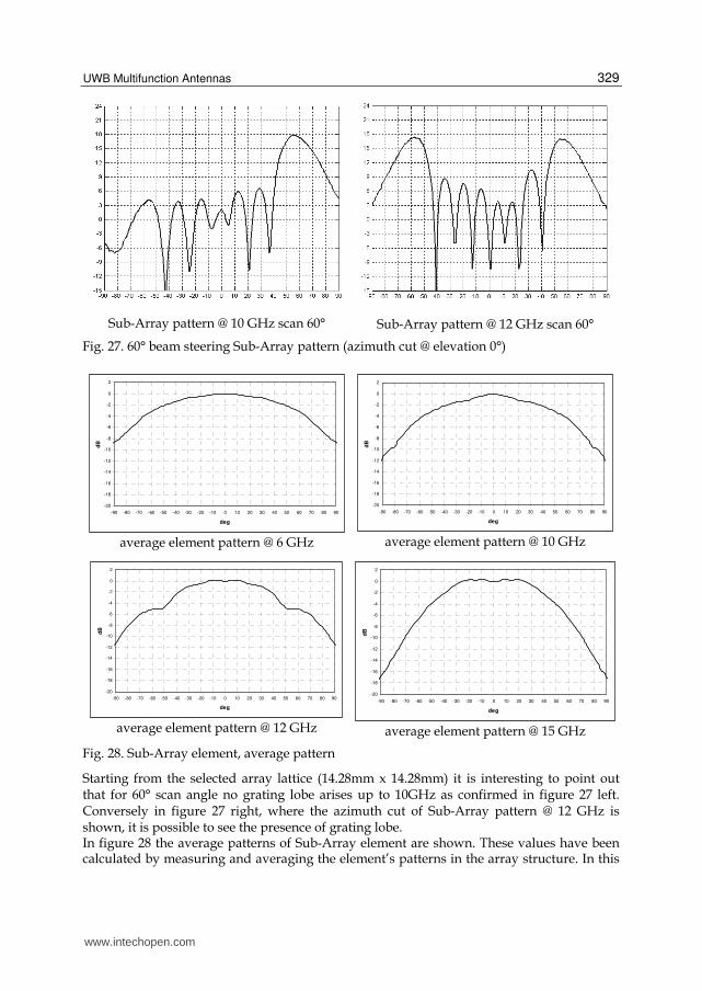
Sub-Array pattern @ 10 GHz scan 60°
Sub-Array pattern @ 12 GHz scan 60°
Fig. 27. 60° beam steering Sub-Array pattern (azimuth cut @ elevation 0°)
-20
-18
-16
-14
-12
-10
-8
-6
-4
-2
0
2
-90 -80 -70 -60 -50 -40 -30 -20 -10 0 10 20 30 40 50 60 70 80 90
deg
dB
average element pattern @ 6 GHz
-20
-18
-16
-14
-12
-10
-8
-6
-4
-2
0
2
-90 -80 -70 -60 -50 -40 -30 -20 -10 0 10 20 30 40 50 60 70 80 90
deg
dB
average element pattern @ 10 GHz
-20
-18
-16
-14
-12
-10
-8
-6
-4
-2
0
2
-90 -80 -70 -60 -50 -40 -30 -20 -10 0 10 20 30 40 50 60 70 80 90
deg
dB
average element pattern @ 12 GHz
-20
-18
-16
-14
-12
-10
-8
-6
-4
-2
0
2
-90 -80 -70 -60 -50 -40 -30 -20 -10 0 10 20 30 40 50 60 70 80 90
deg
dB
average element pattern @ 15 GHz
Fig. 28. Sub-Array element, average pattern
Starting from the selected array lattice (14.28mm x 14.28mm) it is interesting to point out that for 60° scan angle no grating lobe arises up to 10GHz as confirmed in figure 27 left. Conversely in figure 27 right, where the azimuth cut of Sub-Array pattern @ 12 GHz is shown, it is possible to see the presence of grating lobe. In figure 28 the average patterns of Sub-Array element are shown. These values have been calculated by measuring and averaging the element’s patterns in the array structure. In this
www.intechopen.com
Ultra Wideband Communications: Novel Trends – Antennas and Propagation
330
figure the patterns are normalized to the boresight value and represent the “so-called” element factor of the array that represents its scanning losses.
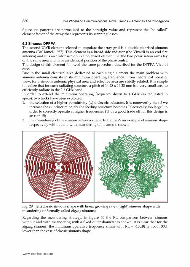
6.2 Sinuous DPPPA The second UWB element selected to populate the array grid is a double polarised sinuous antenna (DuHamel, 1987). This element is a broad-side radiator (the Vivaldi is an end fire antenna) and it is an “intrinsic” double polarised element, i.e. the two polarisation arms lay on the same area and have an identical position of the phase centre. The design of this element followed the same procedure described for the DPPPA Vivaldi case. Due to the small electrical area dedicated to each single element the main problem with sinuous antenna consists in its minimum operating frequency. From theoretical point of view, for a sinuous antenna physical area and effective area are strictly related. It is simple to realize that for such radiating structure a pitch of 14.28 x 14.28 mm is a very small area to efficiently radiate in the 2-6 GHz band. In order to extend the minimum operating frequency down to 4 GHz (as requested in specs), two tricks have been exploited: 1. the selection of a higher permittivity (εr) dielectric substrate. It is noteworthy that if we
increase the εr indiscriminately the feeding structure becomes “electrically too large” in order to correctly operate at higher frequencies (Thus a good trade off for this design is an εr=6.15)
2. the meandering of the sinuous antenna shape. In figure 29 an example of sinuous shape respectively without and with meandering of its arms is shown.
Port1
Port2
Port1
Port2
Fig. 29. (left) classic sinuous shape with linear growing rate τ (right) sinuous shape with meandering (informally called zigzag sinuous)
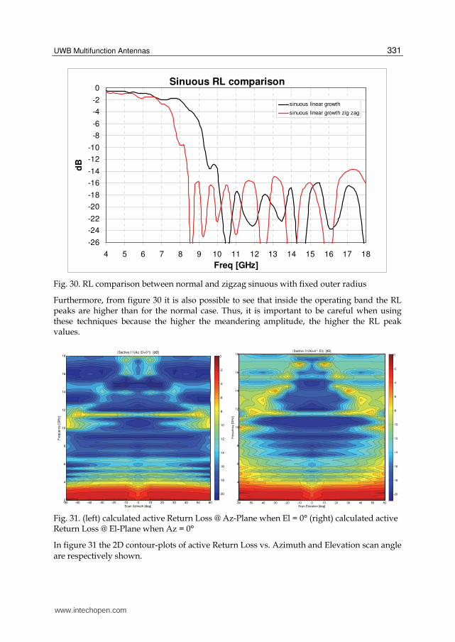
Regarding the meandering strategy, in figure 30 the RL comparison between sinuous without and with meandering with a fixed outer diameter is shown. It is clear that for the zigzag sinuous, the minimum operative frequency (fmin with RL = -10dB) is about 30% lower than the case of classic sinuous shape.
www.intechopen.com
UWB Multifunction Antennas
331
Sinuous RL comparison
-26
-24
-22
-20
-18
-16
-14
-12
-10
-8
-6
-4
-2
0
4 5 6 7 8 9 10 11 12 13 14 15 16 17 18
Freq [GHz]
dB
sinuous linear growth
sinuous linear growth zig zag
Fig. 30. RL comparison between normal and zigzag sinuous with fixed outer radius
Furthermore, from figure 30 it is also possible to see that inside the operating band the RL peaks are higher than for the normal case. Thus, it is important to be careful when using these techniques because the higher the meandering amplitude, the higher the RL peak values.
Scan Azimuth [deg]
Fre
que
ncy [G
Hz]
|Sactive,11(Az, El=0°)| [dB]
-60 -50 -40 -30 -20 -10 0 10 20 30 40 50 602
4
6
8
10
12
14
16
18
-20
-18
-16
-14
-12
-10
-8
-6
-4
-2
0
Scan Elevation [deg]
Fre
qu
en
cy [
GH
z]
|Sactive,11(Az=0°, El)| [dB]
-60 -50 -40 -30 -20 -10 0 10 20 30 40 50 602
4
6
8
10
12
14
16
18
-20
-18
-16
-14
-12
-10
-8
-6
-4
-2
0
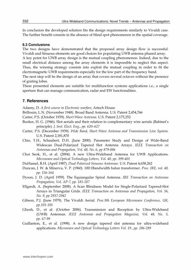
Fig. 31. (left) calculated active Return Loss @ Az-Plane when El = 0° (right) calculated active Return Loss @ El-Plane when Az = 0°
In figure 31 the 2D contour-plots of active Return Loss vs. Azimuth and Elevation scan angle
are respectively shown.
www.intechopen.com
Ultra Wideband Communications: Novel Trends – Antennas and Propagation
332
In conclusion the developed solution fits the design requirements similarly to Vivaldi case.
The further benefit consists in the absence of blind spot phenomenon in the spatial coverage.
6.3 Conclusions The two designs have demonstrated that the proposed array design flow is successful. Vivaldi and Sinuous elements are good choices for populating UWB antenna phased array. A key point for UWB array design is the mutual coupling phenomenon. Indeed, due to the
small electrical distance among the array elements it is impossible to neglect this aspect.
Thus, the winning strategy consists into exploit the mutual coupling in order to fit the
electromagnetic UWB requirements especially for the low part of the frequency band.
The next step will be the design of an array that covers several octaves without the presence
of grating lobes.
These presented elements are suitable for multifunction systems applications i.e., a single
aperture that can manage communication, radar and EW functionalities.
7. References
Adamy, D. A first course in Electronic warfare, Artech House
Brillouin, L.N. (November 1948). Broad Band Antenna. U.S. Patent 2,454,766
Carter, P.S. (October 1939). Short Wave Antenna. U.S. Patent 2,175,252
Booker, H. G. (1946). Slot aerials and their relation to complementary wire aerials (Babinet’s
principle). J. Inst. Elect. Eng., pp. 620–627
Carter, P.S. (December 1939). Wide Band, Short Wave Antenna and Transmission Line System.
U.S. Patent 2,181,870
Chio, T.H., Schaubert, D.H. (June 2000). Parameter Study and Design of Wide-Band
Widescan Dual-Polarized Tapered Slot Antenna Arrays. IEEE Transaction on Antennas and Propagation, Vol. 48, No. 6, pp 879-886
Choi Seok, H., et al. (2004). A new Ultra-Wideband Antenna for UWB Applications. Microwave and Optical Technology Letters, Vol. 40, pp. 399-401
DuHamel, R.H. (April 1987). Dual Polarized Sinuous Antennas. U.S. Patent 4,658,262
Duncan, J. W. & Minerva, V. P. (1960). 100:1Bandwidth balun transformer. Proc. IRE, vol. 48,
pp. 156-164
Dyson, J. D. (April 1959). The Equiangular Spiral Antenna. IRE Transaction on Antennas
Propagation, Vol. AP-7, pp. 181-187
Ellgardt, A. (September 2008). A Scan Blindness Model for Single-Polarized Tapered-Slot
Arrays in Triangular Grids. IEEE Transaction on Antennas and Propagation, Vol. 56,
No. 9, pp 2937-2942
Gibson, P.J. (June 1979). The Vivaldi Aerial. Proc.9th European Microwave Conference, UK,
pp.101-105
Ghosh, D., et al. (October 2006). Transmission and Reception by Ultra-Wideband
(UWB) Antennas. IEEE Antennas and Propagation Magazine, Vol. 48, No. 5,
pp. 67-99
Guillanton, E., et al. (1998). A new design tapered slot antenna for ultra-wideband
applications. Microwave and Optical Technology Letters Vol. 19., pp. 286-289
www.intechopen.com
UWB Multifunction Antennas
333
Kim, Y., Kwon D.H. (April 2004). CPW-fed planar ultra wideband antenna having a
frequency band notch function. Electronics Letters Vol. 40 No. 7, pp. 403 - 405
Liang, J., et al. (September 2004). Printed circular disc monopole antenna for ultra-wideband
applications. Electronics Letters, Vol. 40 No. 20. 30, pp. 1246 – 1247
Licul, S., et al. (October 2003). A parametric study of time-domain characteristics of possible
UWB antenna architectures. IEEE 58th Vehicular Technology Conference, VTC 2003-
Fall, vol. 5, pp. 3110-3114
Lindenblad, N.E., el al. (April 1939). RCA Review
Lindenblad, N.E. (April 1941). Wide Band Antenna. U.S. Patent 2,239,724
Lodge, O. (August 1898). Electric Telegraphy. U.S. Patent 609,154
Lui, W.J., et al. (March 2005). Frequency notched ultra-wideband microstrip slot
antenna with fractal tuning stub. Electronics Letters, Vol. 41 No. 6, 17 March 2005, pp. 9 – 10
Ma, T.G. & Jeng S.K. (Mrch 2005). Planar Miniature Tapered-Slot-Fed Annular Slot
Antennas for Ultrawide-Band Radios. IEEE Transactions on Antennas and
Propagation, vol.53, no.3, pp. 1194-12021
Manna, A., et al. (July 2008). Design, Simulation and Measure of Broadband Cavity Backed
Combined Spiral Antenna. Int Journal of Microwave and Optical Tech (IJMOT), vol. 3,
No. 3, pp. 311-317
Marchand, N. (December 1944). Transmission line conversion transformers. Electronics, vol.
17, pp. 142–145
McFadden, M., Scott, W. R. Jr (November 2007). Analysis of the Equiangular Spiral
Antenna on a Dielectric Substrate. IEEE Trans. Antennas and Propag., vol. AP-55, pp.
3163-3171
Milligan, T.A. (2005). Modern Antenna Design. John Wiley & Sons, Inc, Second Edition.
Misra, V.C. (March 2009). Recent Trends in Antennas for Electronic Warfare Applications. DRDO Science Spectrum, pp. 114-119
Pantano, A., et al. (December, 2007). Optimization of a UWB Vivaldi antenna array and
measurements with a near field Starlab system and farfield anechoic chamber. 11th
International Symposium on Microwave and Optical Technology
Phelan, H.R. (May 1970). A Wide-Band Parallel-Connected Balun. IEEE Transaction on Microwave Theory and Techniques, vol. MTT-18, no. 5, pp. 259-263
Rumsey, V. H. (1966). Frequency Independent Antennas. Academic Press, New York
Saaty, T.L. (1980). The Analytic Hierarchy Process: Planning, Priority Setting, Resource Allocation.
McGraw-Hill, New York
Schantz, H.G., Barnes M. (July 2001). The COTAB UWB Magnetic Slot Antenna. IEEE APS
Schantz, H.G. (2003). Introduction to ultra-wideband antennas. IEEE Conference on Ultra
Wideband Systems and Technologies, pp. 1-9
Schantz, H.G. (2004). Dispersion and UWB Antennas. Proc. Conf. Ultrawideband Systems and Technologies, pp. 161-165
Stockbroeckx, B. (1998). Space wave and surface wave radiation in the Vivaldi Antenna. Ph.
D. dissertation, Catholic University of Louvain., Louvain-la Neuve
Wiesbeck, W., et al. (February 2009). Basic Properties and Design Principles of UWB
Antennas. Proceedings of the IEEE | Vol. 97,No. 2, pp. 372-385
www.intechopen.com

Ultra Wideband Communications: Novel Trends – Antennas and Propagation
334
Ying, C., Zhang, Y.P. (May 2004). Integration of ultra-wideband slot antenna on LTCC
substrate. Electronics Letters, Vol. 40, No. 11, 27, pp. 645 – 646
www.intechopen.com

Ultra Wideband Communications: Novel Trends - Antennas andPropagationEdited by Dr. Mohammad Matin
ISBN 978-953-307-452-8Hard cover, 384 pagesPublisher InTechPublished online 09, August, 2011Published in print edition August, 2011
InTech EuropeUniversity Campus STeP Ri Slavka Krautzeka 83/A 51000 Rijeka, Croatia Phone: +385 (51) 770 447 Fax: +385 (51) 686 166www.intechopen.com
InTech ChinaUnit 405, Office Block, Hotel Equatorial Shanghai No.65, Yan An Road (West), Shanghai, 200040, China
Phone: +86-21-62489820 Fax: +86-21-62489821
This book explores both the state-of-the-art and the latest achievements in UWB antennas and propagation. Ithas taken a theoretical and experimental approach to some extent, which is more useful to the reader. Thebook highlights the unique design issues which put the reader in good pace to be able to understand moreadvanced research.
How to referenceIn order to correctly reference this scholarly work, feel free to copy and paste the following:
Paolo Baldonero, Roberto Flamini, Antonio Manna and Fabrizio Trotta (2011). UWB Multifunction Antennas,Ultra Wideband Communications: Novel Trends - Antennas and Propagation, Dr. Mohammad Matin (Ed.),ISBN: 978-953-307-452-8, InTech, Available from: http://www.intechopen.com/books/ultra-wideband-communications-novel-trends-antennas-and-propagation/uwb-multifunction-antennas