01 Analogici GB 2011:Strumenti analogici ITA 2008 · ANALOGUE INDICATING INSTRUMENTS ... ment,...
31
2011
Transcript of 01 Analogici GB 2011:Strumenti analogici ITA 2008 · ANALOGUE INDICATING INSTRUMENTS ... ment,...

2011


3
ANALOGUE INSTRUMENTSGENERAL DESCRIPTION . . . . . . . . . . . . . . . . . . . . . . . . . . . . . . . . . . . . . . . . . . . . . . . . . . . . . . . . . . . . . . . . . . . . . . . . . . 4
DIMENSIONS . . . . . . . . . . . . . . . . . . . . . . . . . . . . . . . . . . . . . . . . . . . . . . . . . . . . . . . . . . . . . . . . . . . . . . . . . . . . . . . . . . . . 10
VOLTMETERSAC moving iron instruments . . . . . . . . . . . . . . . . . . . . . . . . . . . . . . . . . . . . . . . . . . . . . . . . . . . . . . . . . . . . . . . . . . . . . . . . . . . 11DC moving coil with rectifier for AC system . . . . . . . . . . . . . . . . . . . . . . . . . . . . . . . . . . . . . . . . . . . . . . . . . . . . . . . . . . . . . . . 12DC moving coil instruments . . . . . . . . . . . . . . . . . . . . . . . . . . . . . . . . . . . . . . . . . . . . . . . . . . . . . . . . . . . . . . . . . . . . . . . . . . . 13
AMMETERSAC moving iron instruments . . . . . . . . . . . . . . . . . . . . . . . . . . . . . . . . . . . . . . . . . . . . . . . . . . . . . . . . . . . . . . . . . . . . . . . . . . . 14DC moving coil with rectifier for AC system . . . . . . . . . . . . . . . . . . . . . . . . . . . . . . . . . . . . . . . . . . . . . . . . . . . . . . . . . . . . . . . 15DC moving coil instruments . . . . . . . . . . . . . . . . . . . . . . . . . . . . . . . . . . . . . . . . . . . . . . . . . . . . . . . . . . . . . . . . . . . . . . . . . . . 16
FREQUENCYMETERSPointer instruments . . . . . . . . . . . . . . . . . . . . . . . . . . . . . . . . . . . . . . . . . . . . . . . . . . . . . . . . . . . . . . . . . . . . . . . . . . . . . . . . . 17Vibrating reeds instruments . . . . . . . . . . . . . . . . . . . . . . . . . . . . . . . . . . . . . . . . . . . . . . . . . . . . . . . . . . . . . . . . . . . . . . . . . . . 18
TACHO INDICATORS . . . . . . . . . . . . . . . . . . . . . . . . . . . . . . . . . . . . . . . . . . . . . . . . . . . . . . . . . . . . . . . . . . . . . . . . . . . . . 18
POWER FACTOR METERSWith incorporated electronics
Single phase . . . . . . . . . . . . . . . . . . . . . . . . . . . . . . . . . . . . . . . . . . . . . . . . . . . . . . . . . . . . . . . . . . . . . . . . . . . . . . . . . . . . . 19Three phase, balanced load with neutral . . . . . . . . . . . . . . . . . . . . . . . . . . . . . . . . . . . . . . . . . . . . . . . . . . . . . . . . . . . . . . . 19
With external transducerSingle phase . . . . . . . . . . . . . . . . . . . . . . . . . . . . . . . . . . . . . . . . . . . . . . . . . . . . . . . . . . . . . . . . . . . . . . . . . . . . . . . . . . . . . 19Three phase, balanced load with neutral . . . . . . . . . . . . . . . . . . . . . . . . . . . . . . . . . . . . . . . . . . . . . . . . . . . . . . . . . . . . . . . 20
WATTMETERS AND VARMETERSWith incorporated electronics
Single phase . . . . . . . . . . . . . . . . . . . . . . . . . . . . . . . . . . . . . . . . . . . . . . . . . . . . . . . . . . . . . . . . . . . . . . . . . . . . . . . . . . . . . 20Three phase, balanced load without neutral, 3 wires . . . . . . . . . . . . . . . . . . . . . . . . . . . . . . . . . . . . . . . . . . . . . . . . . . . . . . 20Three phase, unbalanced load without neutral, 3 wires (ARON) . . . . . . . . . . . . . . . . . . . . . . . . . . . . . . . . . . . . . . . . . . . . . 20Three phase, balanced load with neutral, 4 wires . . . . . . . . . . . . . . . . . . . . . . . . . . . . . . . . . . . . . . . . . . . . . . . . . . . . . . . . . 20Three phase, unbalanced load with neutral, 4 wires . . . . . . . . . . . . . . . . . . . . . . . . . . . . . . . . . . . . . . . . . . . . . . . . . . . . . . . 20
With external transducerSingle phase . . . . . . . . . . . . . . . . . . . . . . . . . . . . . . . . . . . . . . . . . . . . . . . . . . . . . . . . . . . . . . . . . . . . . . . . . . . . . . . . . . . . . 22Three phase, balanced load without neutral, 3 wires . . . . . . . . . . . . . . . . . . . . . . . . . . . . . . . . . . . . . . . . . . . . . . . . . . . . . . 22Three phase, unbalanced load without neutral, 3 wires (ARON) . . . . . . . . . . . . . . . . . . . . . . . . . . . . . . . . . . . . . . . . . . . . . 22Three phase, balanced load with neutral, 4 wires . . . . . . . . . . . . . . . . . . . . . . . . . . . . . . . . . . . . . . . . . . . . . . . . . . . . . . . . . 22Three phase, unbalanced load with neutral, 4 wires . . . . . . . . . . . . . . . . . . . . . . . . . . . . . . . . . . . . . . . . . . . . . . . . . . . . . . . 22
SINGLE PHASE INSULATION INSTRUMENTS . . . . . . . . . . . . . . . . . . . . . . . . . . . . . . . . . . . . . . . . . . . . . . . . . . . . . . 23
ELECTRONIC SEQUENCY METERS . . . . . . . . . . . . . . . . . . . . . . . . . . . . . . . . . . . . . . . . . . . . . . . . . . . . . . . . . . . . . . . 23
ELECTRONIC SYNCHRONOSCOPES . . . . . . . . . . . . . . . . . . . . . . . . . . . . . . . . . . . . . . . . . . . . . . . . . . . . . . . . . . . . . . 24
ACCESSORIES . . . . . . . . . . . . . . . . . . . . . . . . . . . . . . . . . . . . . . . . . . . . . . . . . . . . . . . . . . . . . . . . . . . . . . . . . . . . . . . . . . . 24
Hour meters . . . . . . . . . . . . . . . . . . . . . . . . . . . . . . . . . . . . . . . . . . . . . . . . . . . . . . . . . . . . . . . . . . . . . . . . . . . . . . . . . . . . . . . 26Hour meters with certification for fiscal use . . . . . . . . . . . . . . . . . . . . . . . . . . . . . . . . . . . . . . . . . . . . . . . . . . . . . . . . . . . . . . . 28Impulse counters . . . . . . . . . . . . . . . . . . . . . . . . . . . . . . . . . . . . . . . . . . . . . . . . . . . . . . . . . . . . . . . . . . . . . . . . . . . . . . . . . . . 29
HOUR METERS AND IMPULSE COUNTERS
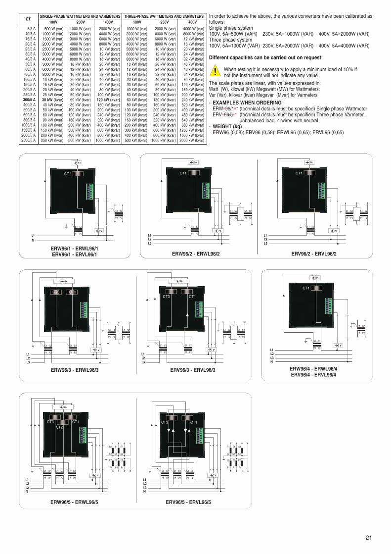
Voltmeter selector switches . . . . . . . . . . . . . . . . . . . . . . . . . . . . . . . . . . . . . . . . . . . . . . . . . . . . . . . . . . . . . . . . . . . . . . . . . . . 30Ammeter selector switches . . . . . . . . . . . . . . . . . . . . . . . . . . . . . . . . . . . . . . . . . . . . . . . . . . . . . . . . . . . . . . . . . . . . . . . . . . . 31Change-over switches . . . . . . . . . . . . . . . . . . . . . . . . . . . . . . . . . . . . . . . . . . . . . . . . . . . . . . . . . . . . . . . . . . . . . . . . . . . . . . . 31Reversing switches . . . . . . . . . . . . . . . . . . . . . . . . . . . . . . . . . . . . . . . . . . . . . . . . . . . . . . . . . . . . . . . . . . . . . . . . . . . . . . . . . 31On-Off switches . . . . . . . . . . . . . . . . . . . . . . . . . . . . . . . . . . . . . . . . . . . . . . . . . . . . . . . . . . . . . . . . . . . . . . . . . . . . . . . . . . . . 31
SWITCHES
01 Analogici GB 2011:Strumenti analogici ITA 2008 14/10/10 16:18 Pagina 3

4
Electrical instruments are capable of measuring an electrical parameter, on the basis of their particular application or function as classified below:
Indicators which give an immediate and continuous indication of the measured valueRecorders which record the variation of input throughout timeIntegrators which integrate throughout time the input signal applied (KWh meters)
ANALOGUE INDICATING INSTRUMENTSGeneral characteristics
These instruments are produced having a pointer which moves over a graduated dial (scale) and assumes different positions according to the varia-tion of the input signal being measured.
The scales of an instrument can be:The linear or uniform type, when the subdivisions are equally dividedThe quadratic type when the subdivision are grouped together at the beginning and are wide at the top, following a quadratic lawOther types, some in accordance with mathematical laws (logarithmic, exponential etc...), others traced empirically
The moving components of an analogue electrical instrument is joined integrally to a rotating axle supported between two fixed brackets which ensu-re their free rotation. The brackets have a spherical seat with a greater radius than that of the pivots.
has adopted pivot suspension with external supports inhard stone which permits a minimum coefficient of wear. The axel iscarried by the lower support while the upper one has the task of gui-ding.
In turn, the upper support has a seat provided with a spring so that itis possible to graduate and maintain throughout time the pressureexercised by the pivots, the spring also has the function of absorbingeventual impacts suffered by the instrument giving greater shock proofqualities.
To enable the pointer to reach the position in a linear and a smoothway, has adopted various methods of damping, causingthe axel to move near to the lower support in a chamber containing avery viscous substance with a base of silicones. The vibration of theshaft and other moving parts are thus reduced and, by reducing theaction developed by the viscous substance, it is possible to obtain thedesired degree of damping which is maintained unaltered throughout.
General description of how the measuring instruments function
Moving iron instruments (AC)With this type of instrument a fixed coil is magnetised which determines the clockwise movement, of a moving iron which is integrally joined to the poin-ter. The scale of these instruments is not linear but has a quadratic trend resulting from this type of mechanism.Specific adjustments of the moving iron make it possible to achieve scales restricted at the bottom. With these instruments the movement is able towithstand peaks of substantial current.Given the particular principle by which this system operates the instruments can function using either Alternating and Direct Currents, however, in thelatter case there is an increase error of indication.
Moving coil instruments (DC)With this type of instrument the magnetic field, generated by a permanently fixed magnet, acts on a moving coil energised by current and is integrallyjoined to the pointer, there by determining the clockwise movement of the latter.This function results in a perfect linear scale.These instruments function only with DC inputs as the direction in which the moving components rotate depends on the correct direction of the pola-rity (during connection it is therefore imperative not to invert the + and - cables).The use of these instruments with alternating current is however possible by using a diode bridge rectifier. By operating in this way however, the instru-ments become very sensitive to the wave form, if not perfectly sinusoidal, and should therefore be used for measuring low values of voltage and cur-rent or if low burden is required.
Bimetal instrumentsWith these types of instruments the deforming of a bimetal element, heated directly or indirectly by the passing of a current, is transmitted to the equip-ment, integrally joined to the pointer. With these instruments the indicator drags, when moving, a second pointer (RED) which indicates the maximumvalue reached. The response time for signals from these instruments is generally eight or fifteen minutes so that short peaks of current are not indica-ted.These instruments can also be combined with moving iron movements for instantaneous measuring of the current values.
ELECTRICAL MEASURING INSTRUMENTS
Pivot pin
Gas ring
Siliconicfluid
Journal-bearing
01 Analogici GB 2011:Strumenti analogici ITA 2008 14/10/10 16:18 Pagina 4

5
Symbols of the main measuring units and their principal multiples
and submultiples
Symbols indicating the principle function of the instrument
and accessory
Symbols indicating the characteristics of the instrument in relation to its con-
nection with the network
kA kiloampereA ampere
mA milliampereµA microamperekV kilovoltV volt
mV millivoltµV microvoltW watt
MW megawattKW kilowattvar var
Mvar megavarkvar kilovar
Hz hertzMHz megahertzkHz kilohertz
Ω ohmMΩ megaohmKΩ kiloohm
T teslamT millitesla°C Celsius
Symbol Specification Symbol Specification
Single-phase direct and alternatingcurrent circuit
Single-phase circuit with alternatingcurrent
Circuit with direct current
Three-phase alternating current circuit(general symbol)
Tree-phase alternating current circuitwith unbalanced load (general symbol)
A measuring element for 3 wirenetworks
A measuring element for 4 wirenetworks
Two measuring elements for 3 wirenetworks with unbalanced load
Two measuring elemenrs for 4 wirenetworks with balanced load
Ferrodymanic instrument (electrodyna-mic with iron)
Instrument with moving iron
Magnetoelectric instrument (withmoving coil and permanent magnet)
Induction instrument
Bimetal instrument
Electronic device in the measuring cir-cuit
Electronic device in an auxiliary circuit
Shunt for measuring instrument
General accessory
Three measuring elements for 4 wirenetworks with unbalanced load
Symbol Specification
Symbols for accuracy class Symbols indicating the working position Symbols regarding safety
500V test voltage
Test voltage of more than 500V (2kVfor example)
Instrument exempt from voltage test
High voltage on the accessory and/oron the instrument
Instrument to use with the dial verticalClass indicator (eg. 1.5) with errorsexpressed in percentage of conventio-nal value, except when the latter is aslong as the graduation or the truevalue
Instrument to use with the dial horizon-tal
Class indicator (eg. 1.5) when the con-ventional value corresponds to thetrue value.
Instrument to use with dial inclined(60° for example) in relation to thehorizontal plane.
Class indicator of an instrument with anon linear scale, contracted in thecase where the conventional value isas long as the graduation and the indi-cation of the error is expressed ad apercentage of the true value. (forexample: class indicator 1: relativeerror limit of 5%) (par. 2.3.11.36)
Symbol Specification Symbol Specification Symbol Specification
If the (1) symbol is associated with the symbol of the instrumentthis means that the device is incorporated.If the (1) symbol is associated with the (2) this means that thedevice is external.
1st figure: protection agains solid bodies 2nd figure: protection against liquids 3rd figure : mechanical protection
IP Tests SpecificationNo protection0
1
2
3
4
5
6
Protected against solid bodies ofmore than 50 mm (eg.: unitentio-nal contact with a hand)
Protected against solid bodies ofmore than 12mm (eg.: a finger)
Protected against solid bodies ofmore than 2.5mm (tools, wires)
Protected against solid bodies ofmore than 1mm (fine tools, thin wires)
Protected against dust (no harmful deposit)
Totally protected against dust.
IP Tests SpecificationNo protection
Protected against drops of waterfalling vertically (condensation)
Protected against drops of waterfalling at an angle of up to 15°from verticalProtected against drops of waterfall at an angle of up to 60° fromverticalProtected against jets of waterfrom all directions
Protected against jets of water inall directions
Protected against water projec-tions like sea waves
Protected against the effects ofimmersion
0
1
2
3
4
5
6
7
IP Tests SpecificationNo protection0
1
2
3
4
5
6
Impact energy: 0,225 joules
Impact energy: 0,375 joules
Impact energy: 0,500 joules
Impact energy: 2,00 joules
Impact energy: 6,00 joules
Impact energy: 20,000 joules
The first two characteristic figures are defined exactly in accordance with the UTE C 20 010 - IEC 144 and DIN 40 050 standardsThe 3rd characteristic figure is defined by the French UTE C 20 010 standard. It is being studied internationally at the CEE - IEC.
(1)
(2)
Ø 50 mm
Ø 12,5 mm
Ø 2,5mm
Ø 1 mm
15 cm
150 g
15 cm
250 g
20 cm
250 g
40 cm
500 g
40 cm
1,5 kg
40 cm
5 kg
60°5%1
1,5
1,5
TABLE OF THE DEGREE OF PROTECTION
SYMBOLS AND THEIR MEANINGS
01 Analogici GB 2011:Strumenti analogici ITA 2008 14/10/10 16:18 Pagina 5

6
The range of measuring instruments are manufactured in accordance with the standards directed by recognise a international organizations.
NORMEThe measuring instruments listed in this catalogue have been manufactured according to the following standards: CEI EN61010-1/CEI EN60051-1-2With regard to the dimensional characteristics of the instruments and shunts, reference is made to the DIN 43700/43718 standards.The most important among these standards are recalled in the following paragraphs relating to the electrical and mechanical characteristics of theinstruments.TEST VOLTAGE - INSULATIONThe instruments are tested according to CEI EN 61010-1 with an effective voltage of 2000V at 50Hz for 1 minute.Greater Test and Insulation voltages can be provided on request for certain types of instruments.ACCURACY CLASSThe accuracy class of the instruments is 1.5 unless otherwise specified, according to CEI EN 60688.Greater precision classes can be provided on request for certain types of instruments.The class of precision is given on the scale of each instrument.OVERLOADThe current coils of all the instruments are capable of withstanding over loading of up to 10 times the nominal current value for periods of less than1 second; and for up to 1,2 times the nominal value permanently.The voltage coils withstands a continuous over loading of up to 1,2 times the nominal voltage and an overloading of up to twice the nominal volta-ge for periods of less than 0,5 seconds (CEI EN 61010-1)For instruments with input by means of C.T., the overload can be greater as the transformer limits the peak of secondary current to values whichare generally less than 10 In.The zerovoltmeters can withstand up to 4 times the full scale voltage for periods of less than 5 minutes.OPERATING TEMPERATUREThe instruments satisfy the requisites of the IEC standards, par. 8.7.1 for which the operating temperature is 20°C +/-10°C. They can however func-tion in continuous service without deterrioration and with an acceptable error of class, with temperatures ranging between -10 °C and +55°C.STORAGE TEMPERATUREThe storage temperature should range from -40°C and +70°C. Temperatures which exceed the two limits can alter the chemical conditions of thesiliconic fluid.HUMIDITYThe instruments are suitable for functioning with a maximum relative humidity of 85% without condensation, at a temperature of +35°C for a maxi-mum of 60 days per year.The relative average annual humidity value should not exceed 65% (DIN 40040 standards). The instruments used in tropicalized conditions can exceed the above-mentioned values and function with a relative maximum humidity of 95%and at a temperature of +35°C. In this case the average annual value of relative humidity should no exceed 75%The instruments used in tropicalized conditions are made to the DIN 40040 standards, according to that, these type of instruments must be pro-tected against the entry of humidity; furthermore all the connection terminals, screws, washers, bolts and magnets are galvanically protected again-st the rust and the printed circuits (if presents) are protected with a special varnish type “Multicolor PC52”.ENVIRONMENTAL CONDITIONSThe equipments are designed to be safe at least under the following conditions: - indoor use - altitude up to 2000 m, or above 2000 m if specified by the manufacturer (see clause D.9 for further information on Standars EN61010-1) - temperature 0°C to 40°C - maximun relative humidity 80% for temperatures up to 31°C decreasing linearly to 50% relative humidity at 40°C - mains supply voltage fluctuations not to exceed +/-10% of the nominal voltage -other supply voltage fluctuations as stated by the manufacturer- transient overvoltages according to installation categories (overvoltage categories) I, II and III (see Annex J on Standards EN61010-1).
For mains supply the minimun and normal category is II- pollution degree 1 or 2 in accordance with IEC 664RESISTANCE TO VIBRATIONThe instruments in the catalogue have passed resistance to vibration tests as established by the CEI 50-4 standards.RESISTANCE TO SHOCKThe instruments have passed shock resistance tests.MOUNTING POSITIONThis series of instruments are made to function in a vertical position.Thanks to perfect balancing they can also be mounted horizontally. Please state mounting method when ordering.FRONT HOUSING FRAMEThe front frame is narrow, according to been DIN 43718/s, and black in colour. The thermoplastic material has the same characteristics as that used for the housing.POINTERSThe pointers of the instruments conform to the DIN 43802 standards. The pointer reaction time is about ≤2 seconds.
QUALITY GUARANTEE
GENERAL TECHNICAL CHARACTERISTICSAll the instruments present on this catalogue haven’t internal fuses protection. It is a matter of specialised technician to consider theirinstallation (if necessary) relating to the declared self-consumption
Measuring instruments are subjected to WORKING VOLTAGES and transient stresses from the circuit to which they are connected during measu-rement. When the measuring circuit is used to measure MAINS, the transient stresses can be estimated by the location within the installation atwhich the measurement is performed. When the measuring circuit is used to measure any other electrical signal, the transient stresses must beconsidered by the user to assure that they do not exceed the capabilities of the measuring equipment.
instruments belong to category III (CAT III - 600V AC et CAT III - 300V DC) considering the measures effected in internal houses(panel).The information concerned the measurement category and the RATED maximum NOMINAL WORKING VOLTAGE or RATED maximum NOMI-NAL CURRENT for such terminals,are putted near these terminals on a label.
MEASURING CIRCUITS (CEI EN 61010-1:2001-11)
01 Analogici GB 2011:Strumenti analogici ITA 2008 14/10/10 16:18 Pagina 6

7
HOUSINGDimensions conform to the DIN 43700/43718 and UNEL 05111 stds.IP52 protection degree for the inside of the instrument (IP40 for modularversion), whereas the terminals have an IP00 degree of protection accordingto CEI 70-1, IEC 529. IP40 protection degree on the terminals can be achieved with the specialrear terminal covers.Housing are made with self-extinguishing thermoplastic according to the UL94standards, V-O classification, resistant to termites and fungus.IP65 protection degree can be achieved with the correspondent accessory AKIP6548(for instruments 48x48), AKIP6572 (for instruments 72x72), AKIP6596(for instruments 96x96) and adopting the following instructions:
1) The hole made in the panel may need to be increased by up 2 mmdepending on the accuracy of the original cut out, in respect to thecorresponding dimensions
2) Position from the back the rubber gasket (A) as shown in the figure3) Position the instrument into the hole made on the panel4) Adapt the front transparent cover (B)5) Secure the instrument against the panel using 4 fixing screws(C)
ZEROINGInstruments can usually be zeroed by means of the special adjustor placed on the front of the instrument. Some types do not require this possibility (Sequencemeters, Hour Counters and meters with a Suppressed Movement).
TERMINALSTerminals are made of brass and are provided with screws and terminal clamps for a good connection.
FITTINGInstrument is secured by two mounting brackets. The mounting brackets can be fitted in two different positions at the rear of the instrument in the firstposition the bracket to rear of panel spacing is 0,5 mm and the second spacing is 19 mm. The bracket mounting system conforms to DIN 43700.For modular version the instruments can be directly fixed on the DIN rail.
AB
Section
A
B
Panel
C
The scales of the instruments in this catalogue conform to the DIN 43802 standards. The instruments for use by means of a C.T. or Shunt canhave interchangeable scales and are made in such a way that it is impossible to touch the pointer or damage the movement while the changeis carried out.
The interchangeable nature of the scale has been specially designed to provide substantial advantages:
Reduction in Storage Costs It is in fact no longer necessary to store a vast assortment of instruments (eg. 40/5A, 80/5A, 300/5A etc.,or 500A/60mV, 1000A/60mV, 5000A/60mV etc.) but only a few instruments without a scale and a numberof loose scale plates provide savings in storage costs.
Reduction in Storage Space As it is no longer necessary to have a large assortment of complete instruments but only loose scales, it isevident that there is a considerable saving of storage space which is always welcome.
Reduction in delivery time Those who do not consider it necessary to create their own instrument stocks will be able to find a largeassortment of instruments and scales at wholesalers, agents and the central headquarters of .
Rapid replacement of the scales The replacement can be carried out by unskilled personnel as it is not necessary to dismantle theinstrument. It is however necessary to pay a minimum amount of attention during this operation inorder not to damage the front of the scale and to ensure that it has been pressed down fully towardsthe bottom of the instrument.
Remove the cover placed in the upper part of the instrument in the direction of the arrows to obtainaccess to the aperture; when this operation has been completed, replace the cover accurately in itsseat to ensure the aperture is completely closed.
Warning: the instrument should not be connected to power during thereplacement operation.
In order to avoid problems caused by incorrect insertions, note the following:the instruments marked 5A1 will only accept scales with a 1 In scale (eg.: 100/5A)the instruments marked 5A2 will only accept scales with a 2 In scale (eg.: 100/200/5A)the instruments marked 5A5 will only accept scales with a 5 In scale (eg.: 100/500/5A)
SCALE PLATES
The length of the graduation on the90° scale is: 48 x 48 and modular = 39 mm72 x 72 = 62 mm96 x 96 = 92 mm144 x144 =135 mm
The normal scales (1 In) of the instruments are:A) 90° scale plate nominal overload 1In
01 Analogici GB 2011:Strumenti analogici ITA 2008 14/10/10 16:18 Pagina 7

8
The length of the graduation on the90° scale is: 48 x 48 and modular = 39 mm72 x 72 = 62 mm96 x 96 = 92 mm144 x144 =135 mm
The length of the graduation on the90° scale is: 48 x 48 and modular = 39 mm72 x 72 = 62 mm96 x 96 = 92 mm144 x144 =135 mm
The length of the graduation on the240° scale is: 48 x 48 = 73 mm72 x 72 = 108 mm96 x 96 = 154 mm144 x144 = 235 mm
B) 90° Scale plates 100% overload (2 In), where the end scale value corresponds to 2 times the nominal value
C) 90° Scale plates 500% overload (5 In), where the end scale value corresponds to 5 times the nominal value
D) 240° Scale plates nominal overload 1In
The length of the graduation on the90° scale is: 48 x 48 and modular = 39 mm72 x 72 = 62 mm96 x 96 = 92 mm144 x144 =135 mm
The length of the graduation on the240° scale is: 48 x 48 = 73 mm72 x 72 = 108 mm96 x 96 = 154 mm144 x144 = 235 mm
The technology adopted by Revalco on the 4/20mA instruments is with use of mechanical zero.Without any current input the pointer is positioned under the zero marked on the scaleplate(Fig.1).Supplying 4mA the pointer goes to the zero (Fig.2), while with 20mA the pointer goes tothe end scale value. In this way all the divisions between 4 and 20mA are well defined.
Zero adjuster of these instruments is disconnected in the factory to avoid possible incor-rect use by the end user. If working zero adjuster is required, please indicate when pla-cing the order.
a 240° a 90°
The scale plates are provided with a reflective mirror to avoidparallax errors during the reading
E) 90° Scale plates 4/20 mA F) 240° Scale plates 4/20 mA
Fig. 2Fig. 1G) Antiparallax scale plates
01 Analogici GB 2011:Strumenti analogici ITA 2008 14/10/10 16:18 Pagina 8

9
Special implementations for scale platesLinear scale plates hand drawnNon linear scale plates hand drawnRed or green markScale plates with unique trace and double or triple num-beringScale plates with double or triple trace and double or tri-ple numberingBlack scale plates with yellow numbering and divisionsAntiparallax scale platesSpecial words or symbolsColoured sectorsPersonalised logo
Special implementations for equipmentCentral or offset zeroClass 1 calibrationD.C. calibrationNon standard frequency calibration (400Hz at 5A)Calibration for other capacities according to curveDifferent capacities from the standardDouble ratioTropicalised executionExecution for marineIP54 protection degreeIP55 protection degreeIP65 protection degree (where possible using theaccessory AKIP65)Antireflex glassAdditional red pointer adjustable from the frontInternal illumination
CertificatesCertificate of conformityTest certificateType test certificateUTF certificate (for kWh meters and CTs only)
••
•
•••••
••
•
••••••••
•••
••
•
•• •
SPECIAL IMPLEMENTATIONSThe instruments in the catalogue can be provided, in special housings, with some variations regarding the scales and equipment.The following table indicates the possible implementation for each series of instruments.
For allInstruments
For all A.C.instruments
For all D.C.instruments
A.C. instruments model ERIL48 (48x48)scale plates 240° are supplied with anexternal accessory (box equal to thearticle TARPDE1)
+
- On request Revalco supplies analogue and digital instruments 72x72, inexplosion proof box putting “REX” prefix code before the standard code.
- Explosion proof box for measuring instruments EEx-d IIC REX series- Zone 1 / 2 / 21 / 22 installation- Category II 2 GD classification- EEx-d IIC T6 execution- IP66 protection degree (EN60 529 standards)- INERIS 02 ATEX 0069X Certificate- Mechanical characteristics: marine aluminium cooper free, temperate glass
port-hole, O-ring gasket in NBR- Safety parameters:
analogue instruments = max voltage input 600VAC or DC= max current 5A input
digital instruments = max auxiliary power supply 110VAC or 230VDC= max current 5A input
- Special safety warning:- dont open the instrument once powered- after disconnection wait for 15 minutes before to open the box- this box assures a relative high protection against the shocks; end user
has in any case to increase this protection when high risks of damagesfor glass or box are possible
- All the components and cables particularly must be conform to thhe 94/9/ECdirectives
- For use in explosive atmosphere the surfaces of various joints must becovered by grease (silicon) while cables must have a protection not less thanIP6X and the operator must clean regularly all the device to avoid depositionof dangerous durst over them.
- Weight: 1,5 kg
- EORDER EXAMPLEREXERI■72500V■D voltmeter 72x72 direct insertion, end scale 500Vin explosion proof boxREXERB■7250/5A15MIN maximum demand ammeter, end scale 50/5A,15 minutes, in explosion proof box
EXPLOSION PROOF VERSION
01 Analogici GB 2011:Strumenti analogici ITA 2008 14/10/10 16:18 Pagina 9

8545
58
52,5
85
58
105
45
10
1290
80 ! ��
�
��
! �
Length graduation: 58 mm
Cut out
Cut out
Cut out with use ofA55R frame
Cut out with use ofA70R frame
A55RE frame
A70R frame
A55NE frame
Length graduation: 78 mm A70N frame
60
1270
DIMENSIONS IN mm
��
�� �
������
������
! ���
�
�
! �
��
�� ��� ������
����
INDICATIONS FOR ORDERINGFor simplicity and evidence the codes are not numerical but nominal; i.e. they immediately indicate the products to order. On the pages of each family of instru-ments however some clarifying examples are given.NOTE: in same cases the codes show empty spaces between the letters displayed with the symbol “ ■ “.So: “ ■ “ means that it is necessary to dial an empty space, “ ■ ■ “ means that it is necessary to dial two empty spaces.
01 Analogici GB 2011:Strumenti analogici ITA 2008 14/10/10 16:18 Pagina 10

AL 1=1secAL 2=1sec
AL 1=1secAL 2=3sec
AL 1=1secAL 2=5sec
AL 1=1secAL 2=15sec
AL 1=3secAL 2=1sec
AL 1=3secAL 2=3sec
AL 1=3secAL 2=5sec
AL 1=3secAL 2=15sec
AL 1=5secAL 2=1sec
AL 1=5secAL 2=3sec
AL 1=5secAL 2=5sec
AL 1=5secAL 2=15sec
AL 1=15secAL 2=1sec
AL 1=15secAL 2=3sec
AL 1=15secAL 2=5sec
AL 1=15secAL 2=15sec
230V
C
Input V
CAL2 AL1
VOLTMETER / FREQUENCY METER ERI72VH- These instruments consint of the combination of a analogue voltmeter with 500V end scale
value, and a three leds electronic circuit for the reading of the frequency. Principally usedin small generating sets where more space is saved.
voltmeter frequency meter with self-powered circuit- BURDEN 3VA 0,5VA- OPERATING FREQUENCY 40÷60 Hz 50 Hz- CLASS 1,5 1- DISPLAY three leds circuit - RANGES 500V 48÷52 Hz- EXAMPLES WHEN ORDERING
ERI■72VH 500V end scale value, led frequency meter from 48 to 52 Hz- WEIGHT (kg) 0,20
MOVING IRON INSTRUMENTS FOR ALTERNATING CURRENTMODULAR VOLTMETER ERIM- BURDEN 1,5VA- OPERATING FREQUENCY 40÷60 Hz - CLASS 1,5- RANGES 6-10-15-25-40-60-100-150-250-300-400-500-600V direct input
.../100V-.../110V input by means a V.T., secondary 100V or 110VDifferent capacities can be carried out on request
- DIMENSIONS / WEIGHT 3 DIN modules / 0,15 kg- EXAMPLES WHEN ORDERING
ERI■M■300V■D direct input, end scale value 300VERIM500V500/100 input by means a V.T. 500/100V, end scale value 500V
VOLTMETER (90°) ERI48 - ERI72 - ERI96 - ERI144- BURDEN 48 = 1,2÷2VA; 72/96/144 = 1,5÷4VA- OPERATING FREQUENCY 40÷60 Hz - CLASS 1,5- RANGES
6-10-15-25-40-60-100-150-250-300-400-500-600V direct input.../100V-.../110V input by means a V.T., secondary 100V or 110VDifferent capacities can be carried out on request
- EXAMPLES WHEN ORDERINGERI■48500V■D direct input, end scale value 500VERI96500V400/100 input by means a V.T. 400/100V, end scale value 500V
- WEIGHT (kg) ERI48 (0,10); ERI72 (0,20); ERI96 (0,30); ERI144 (0,35)
L1N
+-
L1N
VT inputDirect input
VT inputDirect input
11
VOLTMETERS
VOLTMETER WITH INCORPORATED SWITCH ERI72C - ERI96C- Instruments provided with switch, low voltage, for 3 phase-phase and 3 phase-neutral
voltage L1N-L2N-L3N / L1L2-L2L3-L3L1- BURDEN 1,5÷4VA- OPERATING FREQUENCY 40÷60 Hz - CLASS 1,5 - FRONT PROTECTION DEGREE IP00- RANGES 6-10-15-25-40-60-100-150-250-300-400-500-600V direct input
.../100V-.../110V input by means a V.T., secondary 100V or 110VDifferent capacities can be carried out on request
- EXAMPLES WHEN ORDERINGERI72C■500V■D direct input, end scale value 500V
- WEIGHT (kg) 0,25
L1
L2L3
L1
L2L3
a b
A B
a b
A BI II
I II
DOUBLE VOLTMETER ERI96D- These instruments consist of two equipments mounted on a common axis permitting the
two pointers indicating on one graduation. In this way there is the immediate comparisonof the parallel adjustment. The moving coil system reduces drastically the burden and per-mits linear graduations.
- BURDEN 1,5VA- OPERATING FREQUENCY 45/65 Hz - CLASS 1,5- RANGE 2x500V - Different capacities on request- EXAMPLES WHEN ORDERING
ERI■96D500V■D double voltmeter, 2x500V end scale value- WEIGHT (kg) 0,42
VOLTMETER WITH 2 ALARM THRESHOLDSERIC96V - ERIC96V24 - ERIC96V110
- BURDEN 3VA- POWER SUPPLY standard 230V +/-10% - DC auxiliary supply on request - FREQUENCY 45/65 Hz - RANGE 600V - Different capacities on request- RELAYS DATA Max interruption power with resistive laod 2kVA (8A,250V)
ERIC96V=AL 1 (MIN) AL 2 (MAX) ERIC96VMA=AL 1 (MAX1) AL 2 (MAX2)ERIC96VMI=AL 1 (MIN1) AL 2 (MIN2) ERIC96VMM=AL 1 (MAX-) AL 2 (MAX+)
- SIGNALLING DATAAdjustments by 2 frontal buttonsClass +/- 1,5% referred to the end scale valueHysteresis < 1% of end scale valueDelay time from 1 to 15 seconds, selectable by minidip situated under the white frame
- How to select the alarms: press the button (AL1 or AL2) and maintain pressure until thelower led moves to the needed value. In alarm condition all leds flash quickly
- EXAMPLES WHEN ORDERINGERIC96V■ ■600V MIN/MAX voltmeter, end scale 600V (230VAC)
- WEIGHT (kg) 0,50 Delay timeselection
Default delay timeselectionAL1=1 secAL2=1 sec
01 Analogici GB 2011:Strumenti analogici ITA 2008 14/10/10 16:18 Pagina 11

MOVING COIL INSTRUMENTS FOR ALTERNATING CURRENTVOLTMETER (90°) ERR48 - ERR72 - ERR96 - ERR144VOLTMETER (240°) ERIL48 - ERIL72 - ERIL96- These instruments are constructed for the measurement of alternating current, from 25
to 10,000Hz, and are gauged for reading the effective value of the sinusoidal current.For other wave forms please consult us.
- BURDEN 1mA about- CLASS 1,5- RANGES
6-10-15-25-40-60-100-150-250-300-400-500-600V direct input.../100V, .../110V input by means a V.T., secondary 100V or 110VDifferent capacities can be carried out on request
- EXAMPLES WHEN ORDERINGERIL96500V■D direct input, 500V end scale value, 240° ERR■72100V■D direct input, 100V end scale value, 90°
- WEIGHT (kg) ERR48 (0,10); ERR72 (0,20); ERR96 (0,25); ERR144 (0,35)ERIL48 (0,21); ERIL72 (0,30); ERIL96 (0,40)
VT input
Direct input
+-
VOLTMETER (HORIZONTAL PROFILE VERSION) ERPI24/OVOLTMETER (VERTICAL PROFILE VERSION) ERPI24/V- Instruments with internal rectifier- BURDEN 1mA- OPERATING FREQUENCY 40 ÷ 60 Hz- CLASS 1,5- RANGES
6-10-15-25-40-60-100-150-250-300-400-500-600V - Different capacities on request- EXAMPLES WHEN ORDERING
ERPI24/0■ ■60V■D direct input, end scale value 60V (horizontal)ERPI24/V■300V■D direct input, end scale value 300V (vertical)
12
ZEROVOLTMETER (90°) ERZ48 - ERZ72 - ERZ96 - ERZ144 ZEROVOLTMETER (240°) ERZL48 - ERZL72 - ERZL96- These instruments consist of moving coil movements with internal rectifier which can be
used to replace the Sinchronoscope in the synchronizing of two generators or one gene-rator in the network. When the two voltages to be synchronized are the same, the instru-ment indicates “zero”.
- BURDEN 1 mA- RANGES STANDARD from 0 to 50V, extended to 800V
(The instrument can therefore be used with all the voltages as the equipment withstandsup to 800V continuously)
- EXAMPLES WHEN ORDERINGERZ■96■50-800V zerovoltmeter 96x96, 90° end scale valueERZL72■50-800V zerovoltmeter 72x72, 240° end scale value
- WEIGHT (kg) ERZ48 (0,10); ERZ72 (0,20); ERZ96 (0,22); ERZ144 (0,30);ERZL48 (0,22); ERZL72 (0,30); ERZL96 (0,35)
- Modular version (ERZM) on request
VOLTMETER WITH SUPPRESSED ZERO (90°) ERZS48 - ERZS72 - ERZS96 - ERZS144VOLTMETER WITH SUPPRESSED ZERO (240°) ERZSL48 - ERZSL72 - ERZSL96- These instruments consist of moving coil movements and internal rectifier which are used
to determine very precisely the normal value of the sinusoidal alternating voltage.Measuring ranges between 90 to 110% approximately of the voltage.
- BURDEN 1 VA- RANGES 0-90/110V; 0-100/120V; 0-200/240V; 0-340/420V- EXAMPLES WHEN ORDERING
ERZS96340-420 90° scale plate- WEIGHT (kg) ERZS48 (0,10); ERZS72 (0,20); ERZS96 (0,22); ERZS144 (0,30)
ERZSL48 (0,22); ERZSL72 (0,30); ERZSL96 (0,35)
- Modular version (ERZSM) on request
PANEL VOLTMETER EMI55M - EMI70MVOLTMETER WITH 55R OR 70R FRAME EMI55M+A55RE - EMI70M+A70RVOLTMETER WITH 55N OR 70N FRAME EMI55M+A55NE - EMI70M+A70N- Front in plastic, transparent acrylic with antistatic as standard- BURDEN 1,5VA- CLASS 1,5- OPERATING FREQUENCY 40 ÷ 60 Hz- RANGES
6-10-15-25-40-60-100-150-250-300-400-500-600V direct input.../100V, .../110V input by means a V.T., secondary 100V or 110VDifferent capacities can be carried out on request
- EXAMPLES WHEN ORDERINGEMI■55M250V■D direct input, end scale value 250V, diameter 55mmEMI■70M■60V■D direct input, end scale value 60V, diameter 70mm
- WEIGHT (kg) 0,15
VT inputDirect input
01 Analogici GB 2011:Strumenti analogici ITA 2008 14/10/10 16:18 Pagina 12

13
PANEL VOLTMETER EMC55M - EMC70MVOLTMETER WITH 55R OR 70R FRAME EMC55M+A55RE - EMC70M+A70RVOLTMETER WITH 55N OR 70N FRAME EMC55M+A55NE - EMC70M+A70N- Front in plastic, transparent acrylic with antistatic as standard- BURDEN 1000Ω/V- CLASS 1,5- RANGES
MILLIVOLTMETERS: 60-100-150-250-400-600mVVOLTMETERS: 1-1,5-2,5-4-6-10-15-25-40-60-100-150-250-300-400-500-600VDifferent capacities can be carried out on request
- EXAMPLES WHEN ORDERINGEMC■70M300V■ ■D direct input, end scale value 300V, diameter 70mm
- WEIGHT (kg) 0,18
MOVING COIL INSTRUMENTS FOR DIRECT CURRENT
VOLTMETER (90°) ERC48 - ERC72 - ERC96 - ERC144VOLTMETER (240°) ERCL48 - ERCL72 - ERCL96 - The main characteristic of these instruments is their low current consumption, in circuits
where high internal consumption and drop in voltage can bring about measuring errors.The low consumption means that these instruments can also be used with converters,tacho generators or thermocouples. Up to 60A they can be provided with an incorporatedshunt for direct connection, above 60A use a separate shunt.
- BURDEN 1000Ω/V- CLASS 1,5- RANGES
MILLIVOLTMETERS: 60-100-150-250-400-600mVVOLTMETERS: 1-1,5-2,5-4-6-10-15-25-40-60-100-150-250-300-400-500-600VDifferent capacities can be carried out on request
- EXAMPLES WHEN ORDERINGERC■72250V■ ■D direct input, end scale value 250V, 90°ERC■96■ ■5V■ ■D direct input, end scale value 5V, 90°ERCL72250V■ ■D direct input, end scale value 250V, 240°
- WEIGHT (kg) ERC48 (0,10); ERC72 (0,20); ERC96 (0,25); ERC144 (0,35) ERCL48 (0,21); ERCL72 (0,30); ERCL96 (0,40)
MODULAR VOLTMETER ERCM- BURDEN 1000Ω/V- CLASS 1,5- RANGES
MILLIVOLTMETERS: from 60 to 600 mV direct inputVOLTMETERS: 1-1,5-2,5-4-5-6-10-15-20-25-40-60-100-150-250-300-400-500-600V direct inputDifferent capacities can be carried out on request
- DIMENSIONS / WEIGHT 3 DIN modules / 0,20 kg- EXAMPLES WHEN ORDERING
ERC■M■ ■30V■ ■D direct input, end scale value 30VERC■M■250V■ ■D direct input, end scale value 250V
L1N
+-
VOLTMETER (HORIZONTAL PROFILE VERSION) ERPC24/OVOLTMETER (VERTICAL PROFILE VERSION) ERPC24/V- BURDEN 1mA- CLASS 1,5- RANGES:
MILLIVOLTMETERS: 60÷300mVVOLTMETERS: 1-1,5-2,5-4-6-10-15-30-40-50-60-80-100-150-200-250-300-400-500-600VDifferent capacities can be carried out on request
- EXAMPLES WHEN ORDERINGERPC24/V■100V■D direct input, end scale value 100V (vertical)ERPC24/O■ ■10V■D direct input, end scale value 10V (horizontal)
+-
VOLTMETER WITH 2 ALARM THRESHOLDS ERCC96V - ERCC96V24 - ERCC96V110- BURDEN 3VA- POWER SUPPLY standard 230V +/-10% - DC auxiliary supply on request - FREQUENCY 45/65 Hz - RANGES 1-10-50-100-300-600V - Different capacities on request- RELAYS DATA Max interruption power with resistive laod 2kVA (8A,250V)
ERCC96V=AL 1 (MIN) AL 2 (MAX) ERCC96VMA=AL 1 (MAX1) AL 2 (MAX2)ERCC96VMI=AL 1 (MIN1) AL 2 (MIN2) ERCC96VMM=AL 1 (MAX-) AL 2 (MAX+)
- SIGNALLING DATAAdjustments by 2 frontal buttonsClass +/- 1,5% referred to the end scale valueHysteresis < 1% of end scale valueDelay time from 1 to 15 seconds, selectable by minidip situated under the white frame
- How to select the alarms: press the button (AL1 or AL2) and maintain pressure until thelower led moves to the needed value. In alarm condition all leds flash quickly
- EXAMPLES WHEN ORDERINGERCC96V■ ■600V MIN/MAX voltmeter, end scale 600V (230VAC)
- WEIGHT (kg) 0,50
AL 1=1secAL 2=1sec
AL 1=1secAL 2=3sec
AL 1=1secAL 2=5sec
AL 1=1secAL 2=15sec
AL 1=3secAL 2=1sec
AL 1=3secAL 2=3sec
AL 1=3secAL 2=5sec
AL 1=3secAL 2=15sec
AL 1=5secAL 2=1sec
AL 1=5secAL 2=3sec
AL 1=5secAL 2=5sec
AL 1=5secAL 2=15sec
AL 1=15secAL 2=1sec
AL 1=15secAL 2=3sec
AL 1=15secAL 2=5sec
AL 1=15secAL 2=15sec
230V
C
Input V
CAL2 AL1
Delay timeselection
Default delay timeselectionAL1=1 secAL2=1 sec
01 Analogici GB 2011:Strumenti analogici ITA 2008 14/10/10 16:18 Pagina 13

14
MOVING IRON INSTRUMENTS FOR ALTERNATING CURRENTMODULAR AMMETER ERIM- BURDEN 0,3VA- OPERATING FREQUENCY 40 ÷ 60 Hz- CLASS 1,5- RANGES
1-1,5-2,5-4-5-6-10-15-20-25-30A direct input.../1A-.../5A input by means of C.T. with secondary 1A or 5ADifferent capacities can be carried out on request
- DIMENSIONS / WEIGHT 3 DIN modules / 0,15 kg- EXAMPLES WHEN ORDERING
ERI■M■ ■20A■5D direct input, end scale value 20A, 5In (20/100A)ERI■M■ ■ ■5A■1 input with C.T., secondary 5A, 1In without scale plateESI■M■ ■40A■15 scale plate for ERIM, 40A, secondary 5A, 1In
CT inputDirect input
AMMETERS
L1N
+-
L1N
S1 S2
P1 P2
AMMETER (90°) ERI48 - ERI72 - ERI96 - ERI144- BURDEN 48 = 0,3÷0,8VA; 72/96/144 = 0,3÷1,2VA- OPERATING FREQUENCY 40÷60 Hz - CLASS 1,5- RANGES
MILLIAMMETERS: 250, 400, 600, 800, 900 mAAMMETERS: 1-1,5-2,5-4-5-6-10-15-20-25-30-40-50-60A direct input
.../1A, .../5A input by means of C.T. with secondary 1A or 5ADifferent capacities can be carried out on request
- EXAMPLES WHEN ORDERINGERI■72■ ■5A■2 input with C.T., secondary 5A, 2In without scale plateESI■72800A■25 scale plate for ERI72, 800A, secondary 5A, 2In ERI■72■ ■6A■5D direct input, end scale value 6A, 5In (6/30A)
- WEIGHT (kg) ERI48 (0,10); ERI72 (0,20); ERI96 (0,30); ERI144 (0,35)
CT inputDirect input
AMMETER WITH INCORPORATED SWITCH ERI72C - ERI96C- Instruments provided with switch, low voltage, single pole for 3 lines L1-L2-L3- BURDEN 0,3÷1,2VA- OPERATING FREQUENCY 40 ÷ 60 Hz - CLASS 1,5- RANGES .../5A2 input with C.T., secondary 5A, 2In
Different capacities can be carried out on request- FRONT PROTECTION DEGREE IP00- EXAMPLES WHEN ORDERING
ERI96C1K0A■2C5 input with C.T., secondary 5A, 2In, end scale value 1000/2000/5A- WEIGHT (kg) 0,25
MAXIMUM DEMAND AMMETER (INTERCHANGEABLE SCALE PLATE) ERB48 - ERB72 - ERB96- This type of instrument is used to check long over loading in transformers, cable and substations.
They also make it possible to check, economically, distribution networks in the place of very costly recorders.A special sealable knob makes it possible to zero the general indicator. The capacity is 6A for use with .../5A C.T.and maximum over loading of 20%.On request instruments can be provided with a capacity of 1,2A for use with C.T. .../1A.
- BURDEN 2,5VA- CLASS 3- RANGES
- EXAMPLES WHEN ORDERINGERB■48■ ■5A■15MIN input with C.T., secondary 5A, 15 minutes, without scale plateESB■48150A scale plate for ERB48, 150A (150/180/5A)ERB■72■ ■5A■15MIN input with C.T., secondary 5A, 15 minutes, without scale plateESB■72■50A scale plate for ERB72, 50A (50/60/5A)ERB■96■ ■1A■8MIN input with C.T., secondary 1A, 8 minutes, without scale plateESB■96600A scale plate for ERB96, 600A (600/720A)
- WEIGHT (kg) ERB72 (0,20); ERB96 (0,22)
100%1015202530405060
120%1218243036486072
100%80
120125150200250300400
120%96
120150180240300360480
100%500600750800
1000120015002000
120%600720900960
1200140018002400
100%2500300040005000
120%3000360048006000
Primary CT(A)
Scalecapacity
Primary CT(A)
Scalecapacity
Primary CT(A)
Scalecapacity
Primary CT(A)
Scalecapacity
01 Analogici GB 2011:Strumenti analogici ITA 2008 14/10/10 16:18 Pagina 14

15
COMBINED MAXIMUM DEMAND AMMETER (INTERCHANGEABLE SCALE PLATE) ERBC72 - ERBC96- These instruments exploit the combining of thermal equipment with moving iron equipment, permitting deferred
reading (typical of bimetallic systems) combined with instantaneous reading of the current values. The capacityis 6A for moving iron connection .../5A C.T. On request instruments can be provided with a capacity of 1,2A forconnection to a 1A C.T. while the normal over loading in the moving iron system is of 100% and 20% in thebimetallic system.
- BURDEN of the moving iron system: 0,3÷1,2 VA, of the bimetal system: 2,5 VA- CLASS of the moving iron system: 1,5 of the bimetal system: 3- RANGES
- EXAMPLES WHEN ORDERINGERBC96■ ■5A■15MIN input with C.T., secondary 5A, 15 minutes, without scale plateESBC96150A scale plate for ERBC96, 150A (150/180A)
- WEIGHT (kg) ERBC72 (0,22); ERBC96 (0,27)
100%1015202530405060
120%1218243036486072
200%203040506080
100120
100%80
100150200250300400500
120%96
120180240300360480600
200%160200300400500600800
1000
100%600800
100012001500200025003000
120%720960
120014001800240030003600
200%12001600200024003000400050006000
100%40005000
120%48006000
200%8000
10000
PrimaryCT (A) Bimetal Moving iron
Scale capacity PrimaryCT (A) Bimetal Moving iron
Scale capacity PrimaryCT (A) Bimetal Moving iron
Scale capacity PrimaryCT (A) Bimetal Moving iron
Scale capacity
PANEL AMMETER EMI55M - EMI70MAMMETER WITH 55R OR 70R FRAME EMI55M+A55RE - EMI70M+A70RAMMETER WITH 55N OR 70N FRAME EMI55M+A55NE - EMI70M+A70N- Front in plastic, transparent acrylic with antistatic as standard- BURDEN 0,3VA- CLASS 1,5- OPERATING FREQUENCY 40 ÷ 60 Hz- RANGES
MILLIAMMETERS: 250, 400, 600, 800, 900 mA AMMETERS: 1-1,5-2,5-4-5-6-10-15-25-30- 40-50-60A direct input
.../1A, .../5A input with C.T., secondary 1A or 5ADifferent capacities can be carried out on request
- EXAMPLES WHEN ORDERINGEMI■55M■75A■5D direct input, end scale value 75A, 5In (75/375A), Ø55 mmEMI■70M100A■1D direct input, end scale value 100A, 1In (100A), Ø70 mm
- WEIGHT (kg) 0,15
CT inputDirect input
MOVING COIL INSTRUMENTS FOR ALTERNATING CURRENTAMMETER INTERCHANGEABLE SCALE PLATE (90°) ERR48 - ERR72 - ERR96 - ERR144AMMETER INTERCHANGEABLE SCALE PLATE (240°) ERIL48 - ERIL72 - ERIL96- These instruments are constructed for the measurement of alternating current, from 25 to
10,000Hz, and are gauged for reading the effective value of the sinusoidal current. Forother wave forms please consult us.
- BURDEN range less than 600mA = 1÷1,5V, higher = 0,25VA - CLASS 1,5- RANGES
MILLIAMMETERS: 1-1,5-2,5-4-5-6-10-15-20-25-40-60-100-150-250-400-600mAAMMETERS: 1-1,5-2,5-4-5 direct input
.../1A, .../5A input with C.T., secondary 1A or 5ADifferent capacities can be carried out on request
- EXAMPLES WHEN ORDERINGERIL96■ ■5A1 input with C.T., secondary 5A, 1In, without scale plate, 240° ESIL961K5A■5A scale plate for ERIL96, 1500A (1500/5A), 1In ERR■48150MA■D direct input, 150mA, scale plate 90°
- WEIGHT (kg) ERR48 (0,10); ERR72 (0,20); ERR96 (0,25); ERR144 (0,35)ERIL48 (0,21); ERIL72 (0,30); ERIL96 (0,40)
CT inputDirect input
AMMETER WITH 2 ALARM THRESHOLDS ERIC96A - ERIC96A24 - ERIC96A110- BURDEN 3VA- POWER SUPPLY standard 230V +/-10% - DC auxiliary supply on request - FREQUENCY 45/65 Hz - RANGE 5A input with C.T., secondary 5A (1A on request)- RELAYS DATA Max interruption power with resistive laod 2kVA (8A,250V)
ERIC96A=AL 1 (MIN) AL 2 (MAX) ERIC96AMA=AL 1 (MAX1) AL 2 (MAX2)ERIC96AMI=AL 1 (MIN1) AL 2 (MIN2) ERIC96AMM=AL 1 (MAX-) AL 2 (MAX+)
- SIGNALLING DATAAdjustments by 2 frontal buttonsClass +/- 1,5% referred to the end scale valueHysteresis < 1% of end scale valueDelay time from 1 to 15 seconds, selectable by minidip situated under the white frame
- How to select the alarms: press the button (AL1 or AL2) and maintain pressure until thelower led moves to the needed value. In alarm condition all leds flash quickly
- EXAMPLES WHEN ORDERINGERIC96A■ ■100A1 MIN/MAX ammeter, end scale 100/5A (230VAC)
- WEIGHT (kg) 0,50
AL 1=1secAL 2=1sec
AL 1=1secAL 2=3sec
AL 1=1secAL 2=5sec
AL 1=1secAL 2=15sec
AL 1=3secAL 2=1sec
AL 1=3secAL 2=3sec
AL 1=3secAL 2=5sec
AL 1=3secAL 2=15sec
AL 1=5secAL 2=1sec
AL 1=5secAL 2=3sec
AL 1=5secAL 2=5sec
AL 1=5secAL 2=15sec
AL 1=15secAL 2=1sec
AL 1=15secAL 2=3sec
AL 1=15secAL 2=5sec
AL 1=15secAL 2=15sec
Input A
230V
CCAL2 AL1
Delay timeselection
Default delay timeselectionAL1=1 secAL2=1 sec
01 Analogici GB 2011:Strumenti analogici ITA 2008 14/10/10 16:18 Pagina 15

16
MOVING COIL INSTRUMENTS FOR DIRECT CURRENTMODULAR AMMETER ERCM- BURDEN 60mV- CLASS 1,5- RANGES
MICROAMMETERS: 100-150-250-400-500-600µA direct inputMILLIAMMETERSI: from 1 to 600 mA 4/20mA direct inputAMPEROMETRI: 1-1,5-2,5-4-5-6-10-15-20-25-30A direct input
.../60mV input by shunt, secondary 60mVDifferent capacities can be carried out on request
- DIMENSIONS / WEIGHT 3 DIN modules / 0,20 kg- EXAMPLES WHEN ORDERING
ERC■M■ ■60MV■ ■S input by shunt, secondary 60mV, without scale plateESC■M■200A■ ■60MV scale plate for ERCM, 200A/60mVERC■M■ ■ ■5A■ ■D direct input, end scale value 5A
Shunt inputDirect input
L1N
+-
+-
AMMETER INTERCHANGEABLE SCALE PLATE (90°) ERC48 - ERC72 - ERC96 - ERC144AMMETER INTERCHANGEABLE SCALE PLATE (240°) ERCL48 - ERCL72 - ERCL96- The main characteristic of these instruments is their low current consumption, in circuits where high internal con-
sumption and drop in voltage can bring about measuring errors. The low consumption means that these instru-ments can also be used with converters, tacho generators or thermocouples. Up to 60A they can be providedwith an incorporated shunt for direct connection, above 60A use a separate shunt.
- BURDEN 60mV- CLASS 1,5- RANGES
MICROAMMETERS (ERC) 50-60-80-100-150-250-400-600-800-900µAMICROAMMETERS (ERCL) 100-150-250-400-600-800-900µAMILLIAMMETERS: 1-1,5-2,5-4-5-6-10-15-20-25-40-60-100-150-250-400-600-800-900mA
4/20mAAMMETERS: 1-1,5-2,5-4-6-10-15-25-40-60A direct input
.../60mV, .../150mV input by shunt, secondary 60mV or 150mVDifferent capacities can be carried out on request
- EXAMPLES WHEN ORDERINGERC■96■60A■D direct input, end scale value 60A, 90° ERC■96■60MV■ ■S input by shunt, secondary 60mV, without scale plateESC96300A600MV scale plate for ERC96, 300A/60mV
- WEIGHT (kg) ERC48 (0,10); ERC72 (0,20); ERC96 (0,25); ERC144 (0,35) ERCL48 (0,21); ERCL72 (0,30); ERCL96 (0,40)
Direct input
Shunt input
AMMETER (HORIZONTAL PROFILE VERSION) ERPI24/OAMMETER (VERTICAL PROFILE VERSION) ERPI24/V- BURDEN 1mA- OPERATING FREQUENCY 40 ÷ 60 Hz- CLASS 1,5- RANGES: 0,5-1-1,5-2-2,5-5A direct input
.../1A, .../5A input with C.T., secondary 1A or 5ADifferent capacities can be carried out on request
- EXAMPLES WHEN ORDERINGERPI24/0■ ■10AD direct input, end scale value 10A (horizontal)ERPI24/V■ ■50AD direct input, end scale value 50A (vertical)
CT input
Direct input
AMMETER WITH 2 ALARM THRESHOLDS ERCC96A - ERCC96A24 - ERCC96A110- BURDEN 3VA- POWER SUPPLY standard 230V +/-10%
DC auxiliary supply on request - FREQUENCY 45/65 Hz - RANGES
MILLIAMMETERS: 1-20-4/20 mA (other on request)AMMETERS: 60mV, input by shunt (other on request)
- RELAYS DATA Max interruption power with resistivelaod 2kVA (8A,250V)
ERCC96A=AL 1 (MIN) AL 2 (MAX) ERCC96AMA=AL 1 (MAX1) AL 2 (MAX2)ERCC96AMI=AL 1 (MIN1) AL 2 (MIN2) ERCC96AMM=AL 1 (MAX-) AL 2 (MAX+)
- SIGNALLING DATAAdjustments by 2 frontal buttonsClass +/- 1,5% referred to the end scale valueHysteresis < 1% of end scale valueDelay time from 1 to 15 seconds, selectable by minidip situated under the white frame
- How to select the alarms: press the button (AL1 or AL2) and maintain pressure until thelower led moves to the needed value. In alarm condition all leds flash quickly
- EXAMPLES WHEN ORDERINGERCC96A■ ■100A1 MIN/MAX ammeter, end scale 100/60mV (230VAC)
- WEIGHT (kg) 0,50
AL 1=1secAL 2=1sec
AL 1=1secAL 2=3sec
AL 1=1secAL 2=5sec
AL 1=1secAL 2=15sec
AL 1=3secAL 2=1sec
AL 1=3secAL 2=3sec
AL 1=3secAL 2=5sec
AL 1=3secAL 2=15sec
AL 1=5secAL 2=1sec
AL 1=5secAL 2=3sec
AL 1=5secAL 2=5sec
AL 1=5secAL 2=15sec
AL 1=15secAL 2=1sec
AL 1=15secAL 2=3sec
AL 1=15secAL 2=5sec
AL 1=15secAL 2=15sec
Input A
230V
CCAL2 AL1
Delay timeselection
Default delay timeselectionAL1=1 secAL2=1 sec
01 Analogici GB 2011:Strumenti analogici ITA 2008 14/10/10 16:18 Pagina 16

17
WITH POINTERMODULAR VERSION ERFM- Moving coil system with incorporated electronics- BURDEN 1,5 VA- CLASS 0,5- POWER SUPPLY 110 - 230 - 400V ± 20%- THERMIC DRIFT 0,12%/°C- RANGE 45/65Hz
Different capacities can be carried out on request- DIMENSIONS / WEIGHT 3 DIN modules / 0,20- EXAMPLES WHEN ORDERING
ERFM45-65230V power supply 230V, end scale value 45/65HzERFM45-55110V power supply 110V, end scale value 45/55Hz
FREQUENCYMETER
SWITCHBOARD VERSION (90°) ERF48 - ERF72 - ERF96 - ERF144SWITCHBOARD VERSION (240°) ERFL72 - ERFL96- BURDEN 1,5 VA - CLASS 0,5- THERMIC DRIFT 0,12% / °C- RANGES 45/65Hz 110V, 230V or 400V
Different capacities can be carried out on request- EXAMPLES WHEN ORDERING
ERF■9645-65400V power supply 400V, end scale value 45/65Hz (90°)ERFL7245-65230V power supply 230V, end scale value 45/65Hz (240°)
- WEIGHT (kg) ERF48 (0,20); ERF72 (0,22); ERF96 (0,30); ERF144 (0,35)ERFL72 (0,27); ERFL96 (0,35)
DOUBLE FREQUENCYMETER ERF96D- These instruments consist of two equipments mounted on a common axis permitting the
two pointers indicating on one graduation. In this way there is the immediate comparisonof the parallel adjustment. The moving coil system reduces drastically the burden and per-mits linear graduations.
- BURDEN 1,5VA- OPERATING FREQUENCY 45/65 Hz- CLASS 0,5- RANGE 2 x 45/65 Hz (400V)
Different capacities can be carried out on request- EXAMPLES WHEN ORDERING
ERF96D400V45-55 power supply 400V, end scale value 2x45/55 Hz- WEIGHT (kg) 0,45
L1N
+-
L1
L2L3
L1
L2L3
a b
A B
a b
A BI II
I II
Direct input
Shunt input
PANEL AMMETER EMC55M - EMC70MAMMETER WITH 55R OR 70R FRAME EMC55M+A55RE - EMC70M+A70RAMMETER WITH 55N OR 70N FRAME EMC55M+A55NE - EMC70M+A70N- Housing in thermoplastic resin. Front in plastic, transparent acrylic with antistatic as standard- BURDEN 60mV- CLASS 1,5- RANGES
MICROAMMETERS: 50-60-100-150-250-400-500-600-800-900µA direct inputMILLIAMMETERS: 1-1,5-2,5-4-5-6-10-15-20-25-30-40-60-100-150-250-400-600-800-900mA
4/20mAAMMETERS: 1-1,5-2,5-4-5-6-10-15-20-25-30-40-50-60A direct input
.../60mV input with Shunt, secondary 60 mVDifferent capacities can be carried out on request
- EXAMPLES WHEN ORDERINGEMC■70M■60A■ ■D direct input, end scale value 60A, 1In (60A), Ø70 mm
- WEIGHT (kg) 0,18
AMMETER (HORIZONTAL PROFILE VERSION) ERPC24/OAMMETER (VERTICAL PROFILE VERSION) ERPC24/V- BURDEN 1mA- CLASS 1,5- RANGES:
MICROAMMETERS: 25-50-100-150-200-250-500 µAMILLIAMMETERS: 1-5-10-50-100-150-200-250-500-600mA
4/20mAAMMETERS: 1-1,5-2-2,5-3-4-5A direct input
.../60mV input with Shunt, secondary 60 mVDifferent capacities can be carried out on request
- EXAMPLES WHEN ORDERINGERPC24/0■4-20MA direct input, end scale value 4/20mA
Direct input
Shunt input
01 Analogici GB 2011:Strumenti analogici ITA 2008 14/10/10 16:18 Pagina 17

AL 1=1secAL 2=1sec
AL 1=1secAL 2=3sec
AL 1=1secAL 2=5sec
AL 1=1secAL 2=15sec
AL 1=3secAL 2=1sec
AL 1=3secAL 2=3sec
AL 1=3secAL 2=5sec
AL 1=3secAL 2=15sec
AL 1=5secAL 2=1sec
AL 1=5secAL 2=3sec
AL 1=5secAL 2=5sec
AL 1=5secAL 2=15sec
AL 1=15secAL 2=1sec
AL 1=15secAL 2=3sec
AL 1=15secAL 2=5sec
AL 1=15secAL 2=15sec
18
FREQUENCYMETER WITH 2 ALARM THRESHOLDS ERFC96 - ERFC9624 - ERFC96110- BURDEN 3VA- POWER SUPPLY standard 230V +/-10%
DC auxiliary supply on request - FREQUENCY 45/65 Hz - RANGE 45/65 Hz (other on request) Voltage 100÷600V- RELAYS DATA Max interruption power with resistive
laod 2kVA (8A,250V)ERFC96=AL 1 (MIN) AL 2 (MAX) ERFC96MA=AL 1 (MAX1) AL 2 (MAX2)ERFC96MI=AL 1 (MIN1) AL 2 (MIN2) ERFC96MM=AL 1 (MAX-) AL 2 (MAX+)
- SIGNALLING DATAAdjustments by 2 frontal buttonsClass +/- 1,5% referred to the end scale valueHysteresis < 1% of end scale valueDelay time from 1 to 15 seconds, selectable by minidip situated under the white frame
- How to select the alarms: press the button (AL1 or AL2) and maintain pressure until thelower led moves to the needed value. In alarm condition all leds flash quickly
- EXAMPLES WHEN ORDERINGERFC96■4565230V MIN/MAX frequencymeter, end scale value 45/65Hz (230VAC)
- WEIGHT (kg) 0,50
Input V (Hz)
230V
CCAL2 AL1
TACHOMETER INDICATOR
TACHO GENERATOR (D.C.) - 90° ERCT48D - ERCT72D - ERCT96D - ERCT144DTACHO ALTERNATOR (D.C.) - 90° ERCT48A - ERCT72A - ERCT96A - ERCT144ATACHO GENERATOR (D.C.) - 240° ERCTL48D - ERCTL72D - ERCTL96DTACHO ALTERNATOR (D.C.) - 240° ERCTL48A - ERCTL72A - ERCTL96A- These instruments are moving coil and have an incorporated potentiometer, they are suitable for measuring the
number of revolutions on a tacho generator (VDC) or tacho alternator (VAC)- BURDEN 600µA - CLASS 1,5- When ordering, indicate the scale, unit of measurement, input voltage and number of revolutions.- EXAMPLES WHEN ORDERING
ERCT72D 10VDC 1500G/min indicator for tacho generator where 1500 revs per minute correspond to10 VDC, 90° scale plate
ERCTL96A 10VCA 100l/h indicator for tacho alternator where 100 litres per hour correspond to10 VAC, 240° scale plate
- WEIGHT (kg): ERCT48 (0,10); ERCT72 (0,20); ERCT96 (0,25); ERCT144 (0,35)ERCTL48 (0,21); ERCTL72 (0,30); ERCTL96 (0,40)
- Modular version (ERTCMA for tacho alternator VAC - ERTCMD for tacho generator VDC) on request
Tacho generator
WITH VIBRATING REEDSFREQUENCYMETER 11 VIBRATING REEDS ERFV72 - ERFV96- The difference between the periods of vibration of two adjoining reeds is 0,5 or 1 Hz. In the case of two adjoi-
ning reeds vibrating with the same amplitude, the measuring of the frequency will be averaged between the vibra-tion periods of both reeds. If the 50 and 50,5Hz reeds vibrate with the same amplitude, for example, the frequencymeasured will be 50.25Hz.Reading example:
- BURDEN 100V = 1,5VA; 230V = 3 VA; 400V = 4 VA- CLASS 0,5- RANGES 47/53Hz 100V / 230V / 400V 57/63Hz 100V / 230V / 400V
45/55Hz 100V / 230V / 400V 55/65Hz 100V / 230V / 400VDifferent capacities can be carried out on request
- EXAMPLES WHEN ORDERINGERFV■96400V57-63 96x96 frequencymeter, power supply 400V, end scale value 47/63HzERFV■72230V45-55 72x72 frequencymeter, power supply 230V, end scale value 45/55Hz
- WEIGHT (kg) ERFV72 (0,25); ERFV96 (0,30); ERFV144 (0,35)
DOUBLE FREQUENCYMETER 2X11 VIBRATING REEDS ERFVD96- These instruments are formed of two rows of reeds to permit one instrument alone to measure the frequency of
two different lines; it is therefore particulary suitable for paralleling two generators or a generator with the mains.- BURDEN 2x100V = 2x1,5VA; 2x230V = 2x3 VA; 2x400V = 2x4 VA- CLASS 0,5- RANGES 2x47/53Hz 2x100V / 2x230V / 2x400V 2x57/63Hz 2x100V / 2x230V / 2x400V
2x45/55Hz 2x100V / 2x230V / 2x400V 2x55/65Hz 2x100V / 2x230V / 2x400VDifferent capacities can be carried out on request
- EXAMPLES WHEN ORDERINGERFVD96400V57-63 96x96 double frequencymeter, power supply 400V, end scale value 57/63Hz
- WEIGHT (kg) 0,60
Default delay timeselectionAL1=1 secAL2=1 sec
Delay timeselection
01 Analogici GB 2011:Strumenti analogici ITA 2008 14/10/10 16:18 Pagina 18

POWER FACTOR METER (90°) ERFA 96/1POWER FACTOR METER (240°) ERFAL 96/1- These instruments are produced in a single housing with an incorporated electronic circuit- BURDEN voltage circuit: 1,5 VA
current circuit: 0,1 VA- CLASS 2,5- RANGE 0,5-1-0,5 cos ϕ- AUX POWER SUPPLY 100V, 230V, 400V to be specified when ordering- INPUT CURRENT 5A- EXAMPLES WHEN ORDERING
ERFA■96/1■230V power supply 230V, scale plate 0,5-1-0,5 cos ϕ, 90°ERFAL96/1■400V power supply 400V, scale plate 0,5-1-0,5 cos ϕ, 240°
- When testing it is necessary to apply a minimum load of 10% if not the instrumentwill not indicate any value
- Note: Any operation necessary for installing these instruments must take placein the absolute absence of voltage, as there is no insulation between line andinstrument
- On 90° version, pointer is positioned on cos ϕ =1 when not powered; with capacitiveor inductive load the correspondent led will be light on
- WEIGHT (kg) ERFA 96/1 (0,45); ERFAL 96/1 (0,50)
19
SINGLE PHASE WITH INCORPORATED ELECTRONICS
POWER FACTOR METERS
L1N
1
3
112
L1N
1 3112
POWER FACTOR METER (90°) ERFA96/2 POWER FACTOR METER (240°) ERFAL96/2- These instruments are produced in a single housing with an incorporated electronic circuit- BURDEN voltage circuit: 1,5 VA
current circuit: 0,1 VA- CLASS 2,5- RANGE 0,5-1-0,5 cos ϕ- AUX POWER SUPPLY 100V, 230V, 400V to be specified when ordering- INPUT CURRENT 5A- EXAMPLES WHEN ORDERING
ERFA■96/2■230V power supply 230V, scale plate 0,5-1-0,5 cos ϕ, 90°ERFAL96/2■400V power supply 400V, scale plate 0,5-1-0,5 cos ϕ, 240°
- When testing it is necessary to apply a minimum load of 10% if not the instrumentwill not indicate any value
- Note: Any operation necessary for installing these instruments must take placein the absolute absence of voltage, as there is no insulation between line andinstrument
- On 90° version, pointer is positioned on cos ϕ =1 when not powered; with capacitiveor inductive load the correspondent led will be light on
- WEIGHT (kg) ERFA96/2 (0,45); ERFAL96/2 (0,50)
THREE PHASE WITH INCORPORATED ELECTRONICS, BALANCED LOAD WITHOUT NEUTRAL
L2L3
1
3
8 5
L1
L1N
1 358
MODULAR VERSION ERCM + 1CORFP10SWITHCBOARD VERSION (90°) ERC48/72/96/144 + 1CORFP10SWITHCBOARD VERSION (240°) ERCL48/72/96 + 1CORFP10SWITHCBOARD VERSION, WITH 2 ALARM THRESHOLDS ERCC96+ 1CORFP10- These measure consist of a 1mA direct current instrument for use with an external multi-
voltage accessory (1CORFP10). They have been produced separately to permit the rea-ding of the cosϕ with instruments of various designs other than 96x96 mm
- RANGE 0,5-1-0,5 cos ϕA- TECHNICAL DATA ERC... (see the correspondent page)
1CORFP10 Auxiliary power supply (separate): 230V ACNominal input values:voltage: 230V ACcurrent: 5A (1A on types 1CORFP10...B)Output nominal values: (selectable):1 - 5 - 10 - VDC e 1 - 5 - 10 - 20 - 4/20 mADC1 mADC degrees value connection with analogue instrumentsConversion type: proportional to the phase angleResistive load: 700Ω; Class: 0,5Overload: Permanent 2 In / 1,2 Un
Instantaneous 10 In / 2 Un for 1 secOperating frequency: 50 / 60 HzResponse time: ≤ 300 msAlternated residual: ≤ 1%Burden:voltage ≤ 1VA current ≤ 0,8VA aux supply ≤ 4VAGalvanic separation between inputs and outputs:insulation between inputs and outputs, supply 2kV for 1min at 50Hzinsulation between all circuits and earth: 4kV for 1min at 50HzOperating temperature: 0 °C ÷ +55 °C
- When testing it is necessary to apply a minimum load of 10% ifnot the instrument will not indicate any value
- EXAMPLES WHEN ORDERINGCORKIT*=ERC...+1CORFP10 (technical details must be specified)
SINGLE PHASE WITH EXTERNAL TRANSDUCER
+
input by means of C.T. (.../5A)
Signal conversion’s Dip (present on COR)proportional to the phase angle (output in degrees,for use with an analogic instrument)
OFF
1 2 3 4 5 6
ON
1 2 3 4
input by means of C.T.(.../5A) and V.T. (.../100V)
01 Analogici GB 2011:Strumenti analogici ITA 2008 14/10/10 16:18 Pagina 19

20
MODULAR VERSION ERCM + 1CORFP20SWITHCBOARD VERSION (90°) ERC48/72/96/144 + 1CORFP20SWITHCBOARD VERSION (240°) ERCL48/72/96 + 1CORFP20SWITHCBOARD VERSION, WITH 2 ALARM THRESHOLDS ERCC96+ 1CORFP20- These measure consist of a 1mA direct current instrument for use with an external multi-
voltage accessory (1CORFP20). They have been produced separately to permit the rea-ding of the cosϕ with instruments of various designs other than 96x96 mm
- RANGE 0,5-1-0,5 cos ϕA- TECHNICAL DATA ERC... (see the correspondent page)
1CORFP20 Auxiliary power supply (separate): 230V ACNominal input values:voltage: 400V ACcurrent: 5A (1A on types 1CORFP20...B)Output nominal values: (selectable):1 - 5 - 10 - VDC e 1 - 5 - 10 - 20 - 4/20 mADC1 mADC degrees value connection with analogue instrumentsConversion type: proportional to the phase angleResistive load: 700Ω; Class: 0,5Overload: Permanent 2 In / 1,2 Un
Instantaneous 10 In / 2 Un for 1 secOperating frequency: 50 / 60 HzResponse time: ≤ 300 msAlternated residual: ≤ 1%Burden:voltage ≤ 1VA current ≤ 0,8VA aux supply ≤ 4VAGalvanic separation between inputs and outputs:insulation between inputs and outputs, supply 2kV for 1min at 50Hzinsulation between all circuits and earth: 4kV for 1min at 50HzOperating temperature: 0 °C ÷ +55 °C
- When testing it is necessary to apply a minimum load of 10% ifnot the instrument will not indicate any value
- EXAMPLES WHEN ORDERINGCORKIT*=ERC...+1CORFP20 (technical details must be specified)
THREE PHASE WITH EXTERNAL TRANSDUCER, BALANCED LOAD WITHOUT NEUTRAL
input by means of C.T. (.../5A)
input by means of C.T.(.../5A) and V.T. (.../100V)
Signal conversion’s Dip (present on COR)proportional to the phase angle (output in degrees,for use with an analogic instrument)
OFF
1 2 3 4 5 6
ON
1 2 3 4
+
SINGLE PHASE WATTMETER/VARMETER (90°) ERW96/1 - ERV96/1 240° INSTRUMENT ERWL96/1 - ERVL96/1THREE PHASE WATTMETER/VARMETER (90°) 240° INSTRUMENTbalanced load, 3 wires without neutral ERW96/2 - ERV96/2 ERWL96/2 - ERVL96/2unbalanced load, 3 wires without neutral (ARON) ERW96/3 - ERV96/3 ERWL96/3 - ERVL96/3balanced load, 4 wires with neutral ERW96/4 - ERV96/4 ERWL96/4 - ERVL96/4unbalanced load, 4 wires with neutral ERW96/5 - ERV96/5 ERWL96/5 - ERVL96/5- These instruments are produced in a single housing with an incorporated electronic circuit and indicate the Active and Reactive Power- BURDEN ammeter circuit: 0,5VA, input resistance <50mΩ; voltage circuit: 1,5VA, 16 kΩ / V about- INPUT VOLTAGE 100V, 230V, 400V +/- 20%- INPUT CURRENT5A- OVERLOAD 1,2 In continuously, 1,5 In for up to two hours; 2 In for up to five seconds- WHEN ORDERING PLEASE INDICATE:
1) Type of current: single or three-phase; with or without neutral; balanced or unbalanced system; three or four wires2) Voltage: between phases, between phase and neutral. If the voltage transformer is used, please indicate the primary and secondary voltage3) Current: max 5 A for direct connection. If the current transformer is used please indicate the primary and secondary value. 4) Scale value. If not indicated, it is calculated by us according to the following table.
FOR ALTERNATING CURRENT WITH INCORPORATED ELECTRONICS
WATTMETERS AND VARMETERS
By adopting a single instrument with an interchangeable scale and multi-voltage converter it is possible to obtain all the capacities shown on the table below. It is suffi-cient to select the input voltage on the accessory and to insert the scale corresponding to the current transformer used. If for example there is a need for a mono-phase380V Wattmeter (Varmeter) with a C.T. ratio of 300/5A; the corresponding scale to insert into the instrument has a 120KW (KVar) scale.This function only applies if the input voltage is direct and not by means of a V.T. in which case calibration in the factory is preferable. If instead it is necessary totake advantage of the multi-scale function, even if the entry voltage derives from a V.T., eg: 1500/100V, always bearing in mind a mono-phase wattmeter, it is necessaryto seek the voltage constant and therefore 1500:100=15.In order to obtain the scale value to introduce into the indicating instrument, it is necessary to multiply the number found (15) by the value of the scale on the table cor-responding to C.T. 300/5A, which is 30KW (KVar). Therefore 15 x 30KW (KVar) = 450KW (KVar)
01 Analogici GB 2011:Strumenti analogici ITA 2008 14/10/10 16:18 Pagina 20
CT1
L1N
V
CT1
L1L2L3
V
CT1
L1L2L3
V
CT1
L1
CT3
L2L3
V
CT1
L1
CT3
L2L3
V
21
In order to achieve the above, the various converters have been calibrated asfollows:Single phase system100V, 5A=500W (VAR) 230V, 5A=1000W (VAR) 400V, 5A=2000W (VAR)Three phase system100V, 5A=1000W (VAR) 230V, 5A=2000W (VAR) 400V, 5A=4000W (VAR)
Different capacities can be carried out on request
When testing it is necessary to apply a minimum load of 10% ifnot the instrument will not indicate any value
The scale plates are linear, with values expressed in:Watt (W), kilowat (kW) Megawatt (MW) for Wattmeters; Var (Var), kilovar (kvar) Megavar (Mvar) for Varmeters
- EXAMPLES WHEN ORDERINGERW■96/1■* (technical details must be specified) Single phase WattmeterERV■96/5■* (technical details must be specified) Three phase Varmeter,
unbalanced load, 4 wires with neutral- WEIGHT (kg)
ERW96 (0,58); ERV96 (0,58); ERWL96 (0,65); ERVL96 (0,65)
SINGLE-PHASE WATTMETERS AND VARMETERS100V 230V 400V
500 W (var) 1000 W (var) 2000 W (var)1000 W (var) 2000 W (var) 4000 W (var)1500 W (var) 3000 W (var) 6000 W (var)2000 W (var) 4000 W (var) 8000 W (var)2500 W (var) 5000 W (var) 10 kW (kvar)3000 W (var) 6000 W (var) 12 kW (kvar)4000 W (var) 8000 W (var) 16 kW (kvar)5000 W (var) 10 kW (kvar) 20 kW (kvar)6000 W (var) 12 kW (kvar) 24 kW (kvar)8000 W (var) 16 kW (kvar) 32 kW (kvar)10 kW (kvar) 20 kW (kvar) 40 kW (kvar)15 kW (kvar) 30 kW (kvar) 60 kW (kvar)20 kW (kvar) 40 kW (kvar) 80 kW (kvar)25 kW (kvar) 50 kW (kvar) 100 kW (kvar)30 kW (kvar) 60 kW (kvar) 120 kW (kvar)40 kW (kvar) 80 kW (kvar) 160 kW (kvar)50 kW (kvar) 100 kW (kvar) 200 kW (kvar)60 kW (kvar) 120 kW (kvar) 240 kW (kvar)80 kW (kvar) 160 kW (kvar) 320 kW (kvar)
100 kW (kvar) 200 kW (kvar) 400 kW (kvar)150 kW (kvar) 300 kW (kvar) 600 kW (kvar)200 kW (kvar) 400 kW (kvar) 800 kW (kvar)250 kW (kvar) 500 kW (kvar) 1000 kW (kvar)
THREE-PHASE WATTMETERS AND VARMETERS100V 230V 400V
1000 W (var) 2000 W (var) 4000 W (var)2000 W (var) 4000 W (var) 8000 W (var)3000 W (var) 6000 W (var) 12 kW (kvar)4000 W (var) 8000 W (var) 16 kW (kvar)5000 W (var) 10 kW (kvar) 20 kW (kvar)6000 W (var) 12 kW (kvar) 24 kW (kvar)8000 W (var) 16 kW (kvar) 32 kW (kvar)10 kW (kvar) 20 kW (kvar) 40 kW (kvar)12 kW (kvar) 24 kW (kvar) 48 kW (kvar)16 kW (kvar) 32 kW (kvar) 64 kW (kvar)20 kW (kvar) 40 kW (kvar) 80 kW (kvar)30 kW (kvar) 60 kW (kvar) 120 kW (kvar)40 kW (kvar) 80 kW (kvar) 160 kW (kvar)50 kW (kvar) 100 kW (kvar) 200 kW (kvar)60 kW (kvar) 120 kW (kvar) 240 kW (kvar)80 kW (kvar) 160 kW (kvar) 320 kW (kvar)
100 kW (kvar) 200 kW (kvar) 400 kW (kvar)120 kW (kvar) 240 kW (kvar) 480 kW (kvar)160 kW (kvar) 320 kW (kvar) 640 kW (kvar)200 kW (kvar) 400 kW (kvar) 800 kW (kvar)300 kW (kvar) 600 kW (kvar) 1200 kW (kvar)400 kW (kvar) 800 kW (kvar) 1600 kW (kvar)500 kW (kvar) 1000 kW (kvar) 2000 kW (kvar)
CT
5/5 A10/5 A15/5 A20/5 A25/5 A30/5 A40/5 A50/5 A60/5 A80/5 A
100/5 A150/5 A200/5 A250/5 A300/5 A400/5 A500/5 A600/5 A800/5 A
1000/5 A1500/5 A2000/5 A2500/5 A
ERW96/1 - ERWL96/1ERV96/1 - ERVL96/1 ERW96/2 - ERWL96/2 ERV96/2 - ERVL96/2
ERW96/4 - ERWL96/4ERV96/4 - ERVL96/4
ERW96/5 - ERWL96/5 ERV96/5 - ERVL96/5
CT1
L1
CT3
CT2
L2L3N
V
CT1
L1
CT3
L2L3N
V
CT1
L1L2L3N
V
ERW96/3 - ERWL96/3 ERV96/3 - ERVL96/3
01 Analogici GB 2011:Strumenti analogici ITA 2008 14/10/10 16:18 Pagina 21

22
S1 S2
P1 P2
S1 S2
P1 P2
S1
P1
S2
P2
8 219 1S1 S2
P1 P2
S1 S2
P1 P2
S1 S2
P1 P2
S1 S2
P1 P2
210 128 1
1 2 8
L2
L1
16 17 21 23 24
1 mA CC
+ -
400V 230V
C
10 12
V
L3
19
5 6
S1 S2
P1 P2
S1 S2
P1 P2
S1 S2
P1 P2
S1 S2
P1 P2
S2
P2
S1
P1
S2
P2
S1
P1
210 128 1 5 619
S1 S2
P1 P2
S1 S2
P1 P2
S1
P1
S2
P2
21198
90° INSTRUMENTS ERCM - ERC48 (72-96-144) ERCC96 + INSTRUMENTS 240° ERCL48 (72-96) +SINGLE PHASE WATTMETER / VARMETER 1CORPA10 / 1CORPR10 1CORPA10 / 1CORPR10THREE PHASE WATTMETER / VARMETER balanced load, 3 wires without neutral 1CORPA20 / 1CORPR20 1CORPA20 / 1CORPR20unbalanced load, 3 wires without neutral (ARON) 1CORPA30 / 1CORPR30 1CORPA30 / 1CORPR30balanced load, 4 wires with neutral 1CORPA40 / 1CORPR40 1CORPA40 / 1CORPR40unbalanced load, 4 wires with neutral 1CORPA50 / 1CORPR50 1CORPA50 / 1CORPR50 - These measure consist of a 1mA direct current instrument for use with an external multi-voltage accessory (1CORPA/1CORPR). They
have been produced separately to permit the reading of the Active and Reactive Power, also with instruments of various designs otherthan 96x96 mm. This accessory permits the interchangeability of the scale plates as shown on previous page.
- The scale plates are linear with values expressed in: Watt (W), kilowatt (kW), Megawatt (MW), Var (Var), kilovar (kVar) Megavar (MVar) - TECHNICAL DATA ERC... (see the correspondent page)
1CORPA10, 1CORPA20, 1CORPA30, 1CORPA40, 1CORPA50 - 1CORPR10, 1CORPR20, 1CORPR30, 1CORPR40, 1CORPR50:Auxiliary power supply (separate): 230V / 400V ACNominal input values: voltage 400V AC; current 5A (1A for model 1CORP...B)Output nominal values: (selectable): 1 - 5 - 10 - VDC and 1 - 5 - 10 - 20 - 4/20 mA DCResistive load: 700Ω; Class: 0,5Overload: Permanent 2 In / 1,2 Un; Instantaneous 10 In / 2 Un for 1 sec.Operating frequency: 50 / 60 HzResponse time: ≤ 300 msAlternated residual: ≤ 1%Burden: voltage ≤ 1VA current ≤ 0,8VA aux supply ≤ 4VAGalvanic separation between inputs and outputs:
insulation between inputs and outputs, aux supply 2kV for 1min at 50Hzinsulation between all circuits and earth: 4kV for 1min at 50Hz
Operating temperature: 0 °C ÷ +55 °CMeasuring range: 0 ÷ Pn (0 ÷ Qn)Standard calibration: 100V,5A=500W (Var); 230V,5A=1000W (Var); 400V,5A=2000W (Var)
- WHEN ORDERING PLEASE INDICATE:1) Reading instrument type: dimensions2) System type: single phase or three phase, with or without neutral, balanced or unbalanced load; 3 or 4 wire3) Voltage: between phases; between phase and neutral. If the voltage transformer is used please indicate the primary and secondary
value.4) Current: max 5A for direct connection. If a current transformer is used please indicate the primary and secondary value (the C.T. should
however be in class 0,5)5) Desired scale value (if different from standard)
- EXAMPLES WHEN ORDERING CORKIT*=ERC... +1CORP... (technical details must be specified)
FOR ALTERNATING CURRENT WITH EXTERNAL TRANSDUCER
1COR.../1
1COR.../3
1COR.../5
1COR.../2
1COR.../4
01 Analogici GB 2011:Strumenti analogici ITA 2008 14/10/10 16:18 Pagina 22

23
SINGLE PHASE INSULATION INSTRUMENTS
ELECTRONIC SEQUENCY METERS
MODULAR VERSION ERCMMISWITHCBOARD VERSION ERCC96MI - ERC96MI - ERC72MI - ERC48MI- These instruments are used to measure permanently, also with presence of power supply, the insulation toward ground, of single phase
lines with insulated neutral; or the insulation toward the positive and negative DC lines. Reading instruments ERCC....MI are furnished withan external power supply accessory (1RAMI)
- TECHNICAL DATA ERCC96, ERC..., ERCM (see the correspondent page)1RAMI- Power supply 100V AC ±10% - Measure input voltage: max 500VAC- Frequency: 45 ÷ 65 Hz - Burden: 1,5 - 2 VA- Temperature: -10°C ÷ +55 °C - Storage temperature: -40°C ÷ +70 °C- Overload: 1,2 Vn
- EXAMPLES WHEN ORDERING ERCC96MI 100V (ERCC96 Power supply 100V + 1RAMI Power supply 100V)ERC96MI 220C (ERC96 + 1RAMI Power supply 220VDC)ERC96MI 400 (ERC96 + 1RAMI Power supply 400V)ERC72MI 24C (ERC72 + 1RAMI Power supply 24VDC)
A.C. LINE CONNECTION DIAGRAM
D.C. LINE CONNECTION DIAGRAM
1 4
5 8 6 7
+ -
Pow
er s
uppl
y10
0VAC
±10
%, 5
0/60
Hz
Fuses
Fuses
TVR.../100V AC
Fuse2A
Resistance insulation measure0 ÷ 500V max
+-
L1
1 4
L2L3
Fuse
Fuse
Fuse2A
5 8 6 7
Resistance insulation measure0 ÷ 500V max
TVR.../100V AC
0L1
L2L3Sw
itch
+ -
Pow
er s
uppl
y10
0VAC
±10
%, 5
0/60
Hz
+-
+
WITHOUT switch WITH switch
ER
CC
96 e
nd s
cale
5M
ohm
ER
CC
96 e
nd s
cale
5M
ohm
1RA
MI
1RA
MI
MODULAR VERSION 1RSMSWITHCBOARD VERSION ERS72 - ERS96These instruments, for alternating three-phase current, and are used when it isnecessary to know whether the sequence of the phases of a three-phase line are cor-rect or not. If the sequence is exact (L1-L2-L3), the green pilot light comes in; if not,the red pilot light will come on. Should one of the phases be missing, the two pilotlights will come on at the same time with a luminous intensity which will be half theoriginal intensity.- BURDEN 1,5VA- CLASS 0,5- POWER SUPPLY sole from 150V to 600V- DIMENSIONS / WEIGHT (1RSM) 3 DIN modules / 0,15 kg
(ERS72) 72x72/ 0,20 kg(ERS96) 96x96/ 0,30 kg
- EXAMPLES WHEN ORDERINGERS■M■ ■150-600V ERS■72■150-600V ERS■96■150-600V
L1L2L3
1 4
5 86 7
+ -Fuse2A
Resistance insulation measure0 ÷ 500V max
+
-
+
-
Pow
er s
uppl
y 24
VDC
or 2
20VD
C
+-
1 4
Fuse2A
5 86 7
Resistance insulation measure0 ÷ 500V max
Switc
h
+ -
L2L10
+
-
+
-
Pow
er s
uppl
y 24
VDC
or 2
20VD
C
+-
WITHOUT switch WITH switch
ER
CC
96 e
nd s
cale
5M
ohm
ER
CC
96 e
nd s
cale
5M
ohm
1RA
MI
1RA
MI
01 Analogici GB 2011:Strumenti analogici ITA 2008 14/10/10 16:19 Pagina 23

24
SWITHCBOARD VERSION ERSI96- INPUT VOLTAGE TECHNICAL DATA
- Nominal voltage Un: 57, 100, 230, 400 V (to be specified when ordering)- Voltage range: Un +/-20%- Frequency range: 45/65 Hz- Burden (bus-bar): <4 VA- Overload: 1,2 Un continuously; 2 Un for 3 seconds
- MEASURING SECTION TECHNICAL DATA:- Resolution of phase difference display: 20° el. Magnification range: ±15° el.- Magnification resolution: 5° el. Accuracy class (Δϕ=0) ±3° el.
- SYNCHRONISATION SECTION- Voltage difference setting range from 1 to 10% accuracy class ± 2,5 %- Phase difference setting range from 2 to 20° el. accuracy class ± 3° el.- Switch-on delay time range from 0,1 to 1 sec accuracy class ± 10%- Relay: N.O. 250V/50Hz, 6A - impulse duration 120ms
- DIMENSIONS / WEIGHT 96x96 / 0,45- EXAMPLES WHEN ORDERING ERSI96■400V; Synchronoscope with output relay, aux supply 400V
ELECTRONIC SYNCHRONOSCOPES
ACCESSORIES
These instruments are intended for measuring phase difference Δϕ between a bus-bar and a generator.They are provided with a synchronising check relay which ena-bles switch-on of synchronisation when the set parameters are reached. These instruments are equipped with a circular display of phase angle which consists of 18led’s.Momentary phase difference is displayed by led. Within synchronisation range (Δϕ=0° between -15°el and +15°el) resolution is increased to 5°el. If difference of fre-quency between input voltages exceeds 3Hz, three leds above FAST (fgen > frete) or SLOW (fgen < frete) inscription are alternately illuminated. A green SYNC. LED is illu-minated when synchronisation conditions are made. A red ΔU led is illuminated when difference between voltages is above the set value or when the bus-bar voltage islower then 80% of nominal value Un. In these instruments comparison of the input voltage of generator Ugen and net Unet method is used ,through and A/D converter ofthe microprocessor.The input voltages are galvanically insulated by a transformer and a microprocessor controls all the operations of the synchronoscope verifying thevalues of the input voltages coming from the A/D converter, determining the difference of phase (Δϕ) between generator and net. The synchronoscopes are provided withthree potentiometers for settting conditions of a synchronisation relay switch-on at the instrument rear side: for setting permitted phase difference Δϕ, for setting permit-ted voltage difference ΔU, for a delay of synchronisation relay switch-on (DELAY). When phase difference and voltage difference between a generator and bus-bar fortime of delay of synchronisation check relay are within the set limits, the synchronisation check relay is switched on for approx 150ms. In that time the SYNC. Led is illu-minated as well.
ARP433 - instruments 72x72ARP434 - instruments 96x96
ARP432 - instruments 48x96
FRONT PROTECTION SYSTEMS
AKIP6548 - instruments 48x48AKIP6572 - instruments 72x72AKIP6596 - instruments 96x96
A48G - instruments 48x48A72G - instruments 72x72A96G - instruments 96x96
IP65 FRONT PROTECTION
RUBBER GASKETS REAR TERMINAL COVERS
A48C - instruments 48x48A72C - instruments 72x72A96C - instruments 96x96 and 144x144
As indicated remove the terminal cover
BLANK PLATES
ARP48 - instruments 48x48ARP72 - instruments 72x72ARP96 - instruments 96x96
ARP4896 - instruments 48x96
01 Analogici GB 2011:Strumenti analogici ITA 2008 14/10/10 16:19 Pagina 24

25
GLASSES
RED POINTER KIT MAXIMUM DEMAND AMMETER KIT
AKIR48 - instruments 48x48AKIR72 - instruments 72x72AKIR96 - instruments 96x96
AKB72 - instruments 72x72AKB96 - instruments 96x96
The kit is composed by: white frame, glass, red pointer and zeroadjusting for black pointer
The kit is composed by: white frame, glass, red pointer and zero adjusting
AKBC72 - Combined instruments 72x72AKBC96 - Combined instruments 96x96
ADAPTERS
ARAD7248 - adapter 72x72, instruments 48x48ARAD9672 - adapter 96x96, instruments 72x72ARAD9648 - adapter 96x96, instruments 48x48
ARAD722 - adapter 72x72, 2 modules instrumentsARAD723 - adapter 72x72, 3 modules instrumentsARAD962 - adapter 96x96, 2 modules instrumentsARAD963 - adapter 96x96, 3 modules instrumentsARAD964 - adapter 96x96, 4 modules instruments
88ASACDGT - with internal spring
instruments48x48, 72x72 and 96x96 instruments 48x48, 72x72 and 96x96 instruments 36x72 and 48x96
FIXING SYSTEMS
ASF2screws (standard)
ASF21screws with flat terminal to avoid
holes on plastic panels
ASF22screws for synotic switchboardASF1 - with spring
HOW TO MODIFY A 4 DIN MODULES INSTRUMENT INTO A 96X96
ARAD964 + 4 DIN MODULES INSTRUMENT = 96x96 INSTRUMENT
A9690V - instruments 96x96 (90°)
A7290V - instruments 72x72 (90°)
A9690VA - instruments 96x96 (90°) antireflex
A7290VA - instruments 72x72 (90°) antireflex
APG9690 - instruments 96x96 (90°) policarbonate
APG7290 - instruments 72x72 (90°) policarbonate
A4890V - instruments 48x48 (90°)A4890VA - instruments 48x48 (90°) antireflex
APG4890 - instruments 48x48 (90°) policarbonate
A96240V - instruments 96x96 (240°)
A72240V - instruments 72x72 (240°)
A96240VA - instruments 96x96 (240°) antireflex
A72240VA - instruments 72x72 (240°) antireflex
APG96240 - instruments 96x96 (240°) policarbonate
APG72240 - instruments 72x72 (240°) policarbonate
A48240V - instruments 48x48 (240°)A48240VA - instruments 48x48 (240°) antireflex
APG48240 - instruments 48x48 (240°) policarbonate
ARAD482adapter 48x96instruments 36x72
01 Analogici GB 2011:Strumenti analogici ITA 2008 14/10/10 16:19 Pagina 25

26
- The hour meters are instruments for measuring time which are particulary suitable for:- determing the functioning time of electrical machines, elevators, boilers, electrical stoves etc.- determing the intervention time for changing the oil, replacing ball bearings etc. on machinery that is in constant use.- determing the functioning time of new machinery with the purpose of establishing when the guarantee expires, such as current rectifiers,
valves, lamps etc.- determing the sum of the periods during fatigue tests, the duration of electrochemical processes etc.
- In the AC version the instrument is driven by a synchronous motor. The display is composed by 5 entires and 2 decimals (4 mm height)- In the DC version the movement of the motor is adjusted by a quartz crystal with great stability and a frequency such that, at every 22 degrees of oscillation,
an impulse is released when amplified, activates electromagnetic converter. The display is composed by 6 entires and 1 decimal (4 mm height)- At the end of the counter, the counting begin again automatically from zero. It is not possible to reset the device.- The necessary voltage is 1,2....1,6V.- The precision is obtained by means of a variable condenser with a tolerance of +/-0,2 sec/day at room temperature.- Operating temperature: between -10°C and +55°C.- Mounting position is indifferent and the housing is in black plastic material.- The reading class is 1/100 h (36 sec)- This hourmeters are manufactured following the UL, IEC, TGL21-366, DIN Standards
4RH72
4RH96
ADAPTER FRAMES
4RK30Fast-on 6,3x0,8 mmwith screws terminal
4RK46
FIXING SYSTEMS
DIN rail mounting Fast and “U-bolt” fixingsystem
Fast fixingsystem
4RK46D4RK46
4RK46B 4RK46G
- Dimensions in mm
HOUR METERS
AMRK5555AMRK7272 AMRKO58
AMRKO72
AMRK4848
AMRK2448
for 4RK30 for 4RK46
AM72
Fast fixingsystem
4RK47R
4RK47R
01 Analogici GB 2011_Strumenti analogici ITA 2008 24/05/11 12.34 Pagina 26

4RK30 - 4RK30244RK3048 - 4RK3060
4RK30400 - 4RK301236C
4RK46 - 4RK4624 - 4RK46484RK4660 - 4RK46110
4RK46400 - 4RK461050C
4RK47R
4RH72 - 4RH7224 - 4RH72484RH7260 - 4RH72110
4RH72400 - 4RH721050C
4RH96 - 4RH9624 - 4RH96484RH9660 - 4RH96110
4RH96400 - 4RH961050C 4RK46Q
4RK47R
27
1
43
2
START / STOPCounting
5
6
Power supply24...250V AC and DC
Power supply12V AC and DC
1
43
2
Power supply24...250V AC and DC
Power supply12V AC and DC
5
6
STAR
T =
close
d co
ntac
t, co
untin
g ph
ase
STO
P =
open
con
tact
, not
cou
ntin
g ph
ase
If th
e co
ntin
uous
con
ting
is ne
ces-
sary
, mak
e a
brid
ge b
etwe
en te
r-m
inal
s 5
and
6
MODULAR VERSION SINGLE: 1RH24-1RH110-1RH230-1RH400-1RH36CDOUBLE: 1RHD230
- BURDEN 1 W (single); 2 x 1 W (double)- OPERATING FREQUENCY 50 or 60 Hz to specify when ordering- POWER SUPPLY (single) 24 V AC ± 10% Mod. 1RH24 110 V AC ± 10% Mod. 1RH110
230 V AC ± 10% Mod. 1RH230 400 V AC ± 10% Mod. 1RH40012-36 V DC Mod. 1RH36C
(double) 2 x 230V ± 10%- PROTECTION DEGREE IP20- INSULATION CLASS II- READING CLASS (single) 1RH24, 1RH110, 1RH230, 1RH400 1/100h (36 sec)
1RH36C 1/10h (6 min) (double) 2 x 1/100h (36 sec)
- TEMPERATURE working -10°C ÷ +55°C / storage -25°C ÷ +70°C- DISPLAY AC 99999,99 h; DC 99999,9 h / AC 2 x 99999,99 h (double) - DIMENSIONS / WEIGHT kg. 2 DIN modules / 0,10 (single); 0,12 (double)- EXAMPLES WHEN ORDERING
1RH230 hourmeter 230V, frequency 50Hz1RHD230 Double hourmeter 230V, frequency 50Hz
MULTI VOLTAGES 1RH1- BURDEN 0,5 W- OPERATING FREQUENCY 50/60 Hz- SOLE POWER SUPPLY 12V AC and DC or from 24 to 250V AC and DC- PROTECTION DEGREE IP20- INSULATION CLASS II- READING CLASS 1/100h- TEMPERATURE working -10°C ÷ +55°C
storage -25°C ÷ +70°C- DISPLAY 99999,99 h- INPUT not galvanically insulated from power supply- DIMENSIONS / WEIGHT kg. 1 DIN module / 0,08- EXAMPLES WHEN ORDERING
1RH1 modular hourmeter 1DIN module
SWITHCBOARD VERSION
AC DC AC AND DCCURRENT CURRENT CURRENT
4RH-4RK46 4RK30 4RH-4RK46 4RK30 4RK47R - 4RK46Q- BURDEN 1,5VA 1 VA from 0,07 to 2W from 0,04 to 0,2W- POWER SUPPLY (to specify) 110 - 230VAC (+10% / -15%) 10...50 V 12...36V 10...60V / 80...150V /
400VAC (± 5%) 150...250V (+10% / -15%)- FREQUENCY (to specify) 50Hz or 60Hz- DISPLAY 99999,99 h (5 entires + 2 decimals) 999999,9 h (6 entires + 1 decimal) 99999,99 h (5 ent. + 2 dec.)- PROTECTION DEGREE 4RK46.... = IP54 IP40 4RK46 = IP54 IP40 4RK47R = IP65
4RH72 / 4RH96 = IP52 4RH72 / 4RH96 = IP52 4RK46Q = IP54- Using the AM72 frame with the hourmeter type 4RK46, this device change the external dimensions into 74x74 mm- Model 4RK30 is supplied complete of fast fixing system and AMRK2448 frame- Model 4RK46 is supplied with fast fixing system and “U-bolt” fixing system- Model 4RK46D has DIN rail mounting system on the back.- EXAMPLES WHEN ORDERING
4RK46 hourmeter 230V, frequency 50Hz4RH72■110■60HZ hourmeter 110V, frequency 60Hz4RH96■400 hourmeter 400V, frequency 50Hz4RK30■ ■ ■ ■ ■60HZ hourmeter 230V, frequency 60Hz
- WEIGHT (kg): 4RK46 (0,09), 4RH72 (0,18), 4RH96 (0,20), 4RK30 (0,05)
4RH.... 4RK30 4RK46.... 4RK46B...
RANGE
4RK46+AM72
01 Analogici GB 2011_Strumenti analogici ITA 2008 24/05/11 12.34 Pagina 27

28
P1 P2
S1 S2
87
230V
- 45
/60H
z
A
43
P1 P2
S1 S2
P1 P2
S1 S2
P1 P2
S1 S2
A A A
1187
230V
- 45
/60H
z
HOUR METERS WITH CERTIFICATIONS FOR FISCAL USE
MODULAR VERSION WITH INCORPORATED MINIMUM LOAD THRESHOLDOne input current 5A 1RHA315Three input currents 5A 1RHA335One input current 1A 1RHA311Three input currents 1A 1RHA331- BURDEN 1 W- OPERATING FREQUENCY 50/60 Hz- POWER SUPPLY 230V and 100V ± 10% (other on request)- PROTECTION DEGREE IP20- INSULATION CLASS II- READING CLASS 1/100h- TEMPERATURE working -10°C ÷ +55°C
storage -25°C ÷ +70°C- DISPLAY 99999,99 h- LED green light-on = voltage presence
red light-on = working because the minimumload limit is overpassed
- DIMENSIONS / WEIGHT kg. 3 DIN modules / 0,18- Minimum load threshold limit is calibrated in factory at 1/200 of nominal current
So: 0,025A in case of nominal current = 5A0,005A in case of nominal current = 1A
- EXAMPLES WHEN ORDERING1RHA315 hourmeter with one input current 5A, 230V1RHA331 hourmeter with three input currents 1A, 230V1RHA335■ 100 hourmeter with three input currents 5A, 100V
MULTI VOLTAGES MODULAR VERSION 1RH1- BURDEN 0,5 W- OPERATING FREQUENCY 50/60 Hz- SOLE POWER SUPPLY 12V AC and DC or from 24 to 250V AC and DC- PROTECTION DEGREE IP20- INSULATION CLASS II- READING CLASS 1/100h- TEMPERATURE working -10°C ÷ +55°C
storage -25°C ÷ +70°C- DISPLAY 99999,99 h- INPUT not galvanically insulated from power supply- DIMENSIONS / WEIGHT kg. 1 DIN module / 0,08- EXAMPLES WHEN ORDERING
1RH1 modular hourmeter 1DIN module
MODULAR VERSION 1RH230- BURDEN 1 W- OPERATING FREQUENCY 50 Hz- POWER SUPPLY 230V ± 10% (other on request)- PROTECTION DEGREE IP20- INSULATION CLASS II- READING CLASS 1/100h- TEMPERATURE working -10°C ÷ +55°C
storage -25°C ÷ +70°C- DISPLAY 99999,99 h- DIMENSIONS / WEIGHT kg. 2 DIN modules / 0,12- Customer can seal the hourmeter putting it into the proper box (to buy in the maket)- EXAMPLES WHEN ORDERING
1RH230 modular hourmeter 2 DIN modules 230V, 50Hz
MODULAR VERSION 1RH3- BURDEN 1 W- OPERATING FREQUENCY 50 Hz- POWER SUPPLY 230V ± 10% (other on request)- PROTECTION DEGREE IP20- INSULATION CLASS II- READING CLASS 1/100h- TEMPERATURE working -10°C ÷ +55°C
storage -25°C ÷ +70°C- DISPLAY 99999,99 h- LED light-on = voltage presence- DIMENSIONS / WEIGHT kg. 3 DIN modules / 0,18- EXAMPLES WHEN ORDERING
1RH3 modular hourmeter 3 DIN modules 230V, 50Hz
230V 50Hz
L
N
1 4
87
1RHA3151RHA311
1RHA3351RHA331
1
43
2
START / STOPCounting
5
6
Power supply24...250V AC and DC
Power supply12V AC and DC
1
43
2
Power supply24...250V AC and DC
Power supply12V AC and DC
5
6
STAR
T =
close
d co
ntac
t, co
untin
g ph
ase
STO
P =
open
con
tact
, not
cou
ntin
g ph
ase
If th
e co
ntin
uous
con
ting
is ne
ces-
sary
, mak
e a
brid
ge b
etwe
en te
r-m
inal
s 5
and
6
01 Analogici GB 2011:Strumenti analogici ITA 2008 14/10/10 16:19 Pagina 28

Ø 3,2
Ø 3,2
Ø 6
Ø 5
10 97
8
5,5
5
29
REVALCO is able to give a complete certification service in order to obtain from the Custom Agency/UTF the FISCAL LICENCE permission relieving the final customer toloose a lot of time.The certificates must be requested during the order.
LN
SWITHCBOARD VERSION 4RK46- BURDEN 1,5 VA- OPERATING FREQUENCY 50 Hz- POWER SUPPLY 230V ± 10% (other on request)- PROTECTION DEGREE IP54- INSULATION CLASS II- READING CLASS 1/100h- TEMPERATURE working -10°C ÷ +55°C; storage -25°C ÷ +70°C- DISPLAY 99999,99 h- DIMENSIONS / WEIGHT kg 55x55x56 / 0,09- Customer can seal the hourmeter putting it into the proper box (to buy in the maket)- EXAMPLES WHEN ORDERING
4RK46 hourmeter 230V, 50Hz
“FULL CERTIFICATION SERVICE “ FOR FISCAL USE – RCCM
Impulse counters are designed to count electrical impulses received from various sources i.e. photocopies, bottles on a conveyor, rotating wheels etc.The RSI.62 series impulse counters are of robust construction and are designed to withstand mechanical shock.It is not possible to reset the counters
AC CURRENT DC CURRENT- BURDEN 1,2W power supply from 6 to 110 VAC 1,2W
4W power supply 230VAC- POWER SUPPLY to specify when ordering:
6 - 12 - 24 - 48 - 60 - 110 - 230VAC (±10%) 6 - 12 - 24 - 48 - 60 - 110VDC (±10%)- DISPLAY 999999 - 6 entires - height 4 mm- MINIMUM DURATION OF IMPULSE 100ms 50ms- MINIMUM DURATION OF PAUSE 100ms 50ms- OPERATING TEMPERATURE -10°C ÷ +50°C- MECHANICAL LIFE 20
6operations
- TEST VOLTAGE 500V - 50Hz- COUNTING SPEED 10 impulses/sec- WEIGHT (kg) 0,09- EXAMPLES WHEN ORDERING 5RSI62.4 (impulse counter 230VAC); 5RSI62■110 (impulse counter 110VAC)
IMPULSE COUNTERS
29,2
25,5
22,2
Ø 2,4
5,1
22,5
Front fixing
Rear fixing
5RSI62.0 5RSI62.4
0 1 2 3 4 5
35
35+
0,1
45 5,1
22,5
23 35
Ø 3,2
30
48,330,5
7
5,5
57 47,2
5RSI62.2
01 Analogici GB 2011:Strumenti analogici ITA 2008 14/10/10 16:19 Pagina 29

30
4540
52,5
58
DIMENSIONS in mm
37
37
4,5
28
10
3,5
Panel cut out rear of board version
Panel cut outin the slot-in
version
35,5
45
14,4
16
44,4
6,5
44 x
34,
7
Each pole more,14,4 mm must be added
max 6
Accessory: AR109DFFlexible transparent protectivecasing for switchboard version)
58
8545
52,5
The cam switches shown in this catalogue have been constructed in accordance with the specifications contained inthe CEI 23-11, CEI 17-11, IEC 408, CEE 24, VDE 0660 T107.- The contacts are electrosoldered in Silver/Nickel, and the contact angle is 45°- The voltage referring to the insulation is 660V (690V for swithboard version) with AC1 nominal current = 12A- The mechanical life is 1.5 million operations with running temperature.
Running temperature ranging from -20°C to + 60°C.- Burden less than 0,5W/pole- The degrees of protection on the clamps is in IP40- This protection can however be increased with the use (after assembly) of the special types of protection. For these pieces of equipment an earth clamp is not required as all the rotating parts are completely isolated fromthe parts carrying voltage.On request, switches with special diagrams are also produced.
VOLTMETER SELECTOR SWITCHES
L3L1L2L3L1L2
0L1NL2NL3N
1 3
2 4
5 7
6 8
9
10
11
12
L1L2
2
L3
1 5 9
12
N
3
0L1L2L2L3L3L1
1 3
2 4
5 7
6 8
L1L2
2
L3
1 3 5
8
0L1NL2NL3N
1 3
2 4
5 7
6 8
L1L2
2
L3N
1 3 5 7
8
PHASE-NEUTRALCONNECTION
2 elements
PHASE-PHASECONNECTION
2 elements
PHASE-PHASE ANDPHASE-NEUTRAL CONNECTION
3 elements
PHASE-PHASE FOR TWODIFFERENT LINES CONNECTION
4 elements
2RCO1215QP switchboard version1RCO1215D modular version
2RCO1216QP switchboard version1RCO1216D modular version
2RCO1218QP switchboard version1RCO1218D modular version
2RCO1217QP switchboard version
PHASE-PHASE AND PHASE-NEUTRALCONNECTION IN CASE
1RCO1218DS 3 DIN modules
L1L2
1
L3N
7 9 11 6
3
SWITCHES
01 Analogici GB 2011:Strumenti analogici ITA 2008 14/10/10 16:19 Pagina 30
31
AMMETER SELECTOR SWITCHES
0
L1
L2
L3
1 3
2 4
5 7
6 8
9
10
11
12
L1L2
2
L3
1 5 9
4
P1 P2
s1 s2
A
P1 P2
s1 s2 P1 P2
s1 s2
2RCO1222QP switchboard version1RCO1222D modular version
1RCO1222DS 3 DIN modules
L1L2
1
L3
7 8 9 10 11
2
P1 P2
s1 s2
A
P1 P2
s1 s2 P1 P2
s1 s2
12
SINGLE POLE 3 CTs3 elements
SINGLE POLE 3 CTs IN CASE3 elements
102
1 3
2 4
5
6
7
8
9
10
11
12
L1L2
1 5L3
9
2 6 10u v w
M3~
4 8 12u v w
M3~
102
1 3
2 4
5
6
7
8
L1L2
1
2
4
5
6
8
102
1 3
2 4
L1L2
1
2
4
101
1 3
2 4
5 7
6 8
9
10
L1L2
9 5
L3
1
10 6 4u v w
M3~
CHANGE-OVER SWITCHES REVERSING SWITCHES
SINGLE POLE1 element
2 POLES2 elements
3 POLES3 elements
3 POLES3 elements
SINGLE POLE1 element
2 POLES2 elements
3 POLES3 elements
4 POLES4 elements
1RCO1205D modular version 1RCO1206D modular version 1RCO1207D modular version 1RINV1208D modular version
1RIN1201D modular version 1RIN1202D modular version 1RIN1203D modular version 1RIN1204D modular version
L1L2
1 3
L3
5
2 4 6u v w
M3~
N7
8n
10
1 3
2 4
5
6
7
8
L1L2
1 3
L3
5
2 4 6u v w
M3~
10
1 3
2 4
5
6
L1L2
1
2
3
4
10
1 3
2 4
L1L2
1
2
10
1
2
ON-OFF SWITCHES
01 Analogici GB 2011:Strumenti analogici ITA 2008 14/10/10 16:19 Pagina 31