


Languages
Pages
Legal

RTO-AG-AVT-140 20 - 1
Chapter 20 – PREVENTION OF HYDROGEN EMBRITTLEMENT IN HIGH STRENGTH STEELS, WITH EMPHASIS ON
RECONDITIONED AIRCRAFT COMPONENTS
R.J.H. Wanhill
National Aerospace Laboratory Amsterdam
NETHERLANDS
S.A. Barter, S.P. Lynch and D.R. Gerrard
Defence Science and Technology Organization Fishermans Bend, Victoria
AUSTRALIA
20.1 INTRODUCTION Failures owing to Hydrogen Embrittlement (HE) (or hydrogen-assisted cracking) appear to be encountered more often in new components than in re-conditioned components. However, since only a small proportion of components are reconditioned, it is likely that hydrogen embrittlement failures are relatively more common for reconditioned components.
When new components fail by hydrogen embrittlement (usually after short times in service), this is mainly because the Original Equipment Manufacturers’ (OEMs) specified procedures for finishing processes, such as electroplating and baking, have not been followed, resulting in significant hydrogen concentrations in the steel. On the other hand, during reconditioning it is more likely that the procedures have nominally been followed, but incorrectly, since they are more complex, involving cleaning, paint-stripping, plating removal, and restoration of worn areas, as well as re-applying the original corrosion or wear-resistant coatings. Reconditioning may also be carried out under less controlled conditions at maintenance facilities or in the field (perhaps by less specialised personnel) compared with the conditions specified by the OEMs for finishing new components.
The preceding (1985) AGARD Corrosion handbook [1] contains a chapter on hydrogen embrittlement, but not the possible problems arising from improper reconditioning. This previous chapter includes eight case histories, all with respect to cracking in high strength steel components. Seven cases were attributed to hydrogen pick-up during electroplating, and one to a surface gouge that may have occurred during re-installation of a used component.
In the present chapter the basic aspects of hydrogen embrittlement are summarised, followed by a review of the testing procedures used for assessing whether or not embrittlement is likely to be produced by finishing processes. Case histories are presented for failures involving hydrogen embrittlement owing to reconditioning of components, and also where there were concerns that embrittlement could have occurred or might occur. Several cases illustrate that improper reconditioning or reconditioning outside the normal standard conditions do not necessarily constitute a risk of hydrogen embrittlement occurring in service, although they do warrant assessment on a case-by-case basis.
Service experience, including some of the above-mentioned cases, and laboratory testing have demonstrated that hydrogen pick-up during electroplating of high strength steels is the main source or risk of hydrogen embrittlement in aircraft components when the corrosion protective scheme is adequate. However, failures of electroplated high strength steel components need not, of course, be due to hydrogen embrittlement, and can occur by Stress Corrosion Cracking (SCC), fatigue and corrosion fatigue, and combinations of these and other failure modes.
PREVENTION OF HYDROGEN EMBRITTLEMENT IN HIGH STRENGTH STEELS, WITH EMPHASIS ON RECONDITIONED AIRCRAFT COMPONENTS
20 - 2 RTO-AG-AVT-140
20.2 BASIC ASPECTS OF HE
20.2.1 Types of HE There are five main types of HE in metallic materials, which are distinguished either according to the source of hydrogen or the mechanism of damage:
1) Internal (Reversible) HE, so called because it is due to the presence of solute hydrogen that can be removed by ‘baking’ at low-to-intermediate temperatures, but which otherwise diffuses to favoured sites (see Section 20.2.5) where weakening of interatomic bonds can lead to crack initiation and growth.
2) Hydride-Induced Embrittlement, which occurs in metals such as titanium, zirconium, vanadium and niobium, owing to the formation and fracture of brittle hydrides that precipitate when sufficiently high internal concentrations of hydrogen are present. Heat treatment can dissolve the hydrides and remove the resulting solute hydrogen.
3) Hydrogen Environment Embrittlement, where susceptible materials crack in the presence of external gaseous hydrogen or hydrogen sulphide.
4) Internal Irreversible HE, whereby solute hydrogen is present in such high concentrations that hydrogen gas precipitates at voids or inclusion/matrix interfaces. The resulting high gas pressures cause blistering or cracking.
5) Hydrogen Attack (or Hydrogen-Reaction Embrittlement), whereby cracking or blistering occurs in environments containing hot hydrogen-bearing gases. The hydrogen diffuses into the metal to carbides or oxides and then produces high-pressure methane or steam.
The only type of major interest for aircraft components is Internal (reversible) HE (IHE) of high strength steels. Hydride-induced embrittlement has occasionally been observed for titanium and titanium alloy components as has IHE of specific α + β titanium alloys, but since these instances are rather rare they will not be further addressed here.
We note here that Stress Corrosion Cracking (SCC) in moist air or aqueous environments is treated as a separate phenomenon, although in many materials, including high strength steels, SCC involves hydrogen embrittlement due to hydrogen generated at crack tips.
20.2.2 Susceptibility of Materials to IHE Structural materials with high strength are the most sensitive to IHE. The following lists groups of common aerospace materials according to their IHE susceptibility:
1) High and ultrahigh strength martensitic steels with yield strengths >1400 MPa (Rockwell C hardness > 38 HRC) are extremely susceptible to IHE, being embrittled by solute hydrogen concentrations as little as 1 ppm. Lower strength martensitic and ferritic steels are less susceptible and require higher hydrogen concentrations for embrittlement to occur. For martensitic steels there is a “step change” to much lower susceptibilities at yield strengths below about 1200 MPa (37 HRC) [2].
2) Titanium alloys with α + β microstructures are susceptible to IHE when solute hydrogen concentrations are ≥ 100 – 200 ppm (with hydride formation not necessarily involved).
3) Nickel alloys, aluminium alloys, low strength ferritic steels, austenitic steels, and copper alloys, show little if any embrittlement from internal hydrogen; and if slight embrittlement does occur it is not of practical importance. Note: high strength nickel alloys are very susceptible to hydrogen environments (hot and/or high pressure gas). Such environments have caused problems with rocket motor components.
PREVENTION OF HYDROGEN EMBRITTLEMENT IN HIGH STRENGTH STEELS, WITH EMPHASIS ON RECONDITIONED AIRCRAFT COMPONENTS
RTO-AG-AVT-140 20 - 3
20.2.3 Important Variables for IHE Besides steel strength and hydrogen content, already mentioned in Section 20.2.2, other important variables are:
1) Applied stress, stress gradients, strain-rate, stress states (plane strain or plane stress) and stress modes: • High triaxial stresses, which occur ahead of sharp notches under plane strain mode I (tensile)
loading, are especially detrimental when the loading is sustained or takes place under slow-strain-rate conditions, see Section 20.4.
• Tensile residual stresses, e.g., produced by abusive grinding, would obviously also be detrimental.
2) Temperature – maximum embrittlement usually occurs at about 20ºC for high strength steels. At lower temperatures the cracking rates are reduced by lower hydrogen diffusion rates, while at higher temperatures the hydrogen adsorption kinetics decrease.
3) Steel composition – the presence of large inclusions and the segregation of metalloid impurities to grain boundaries is especially detrimental.
20.2.4 Sources of Internal Hydrogen The main sources of solute hydrogen in high strength steel aircraft components are the finishing or reconditioning solutions used to clean and apply protective coatings, such as:
1) Electroplating solutions. 2) Pickling solutions. 3) Phosphating solutions. 4) Some paint-stripping solutions. 5) Cathodic cleaning solutions.
Corrosion of sacrificial coatings, such as cadmium, or corrosion pitting during service can also generate hydrogen, especially if the coatings are porous.
In other industries hydrogen can be introduced by:
1) Welding (or melting/casting the original material) in moist atmospheres or with moisture in rust, fluxes, paints or hydrocarbon contaminants.
2) Heat treatment in hydrogen-bearing atmospheres.
3) Cathodic over-protection using anodes or impressed current devices for corrosion protection.
20.2.5 Sites and Traps for Hydrogen in Steels Solute hydrogen in steels occupies and diffuses between octahedral interstitial sites, and can be ‘trapped’ to varying degrees at other sites, viz:
1) Dislocation cores and dislocation strain fields.
2) Prior austenite and martensite-lath boundaries.
3) Carbide- and inclusion-matrix interfaces.
4) Internal voids and vacancy clusters.
5) Voids at interfaces between coatings and steel surfaces.
PREVENTION OF HYDROGEN EMBRITTLEMENT IN HIGH STRENGTH STEELS, WITH EMPHASIS ON RECONDITIONED AIRCRAFT COMPONENTS
20 - 4 RTO-AG-AVT-140
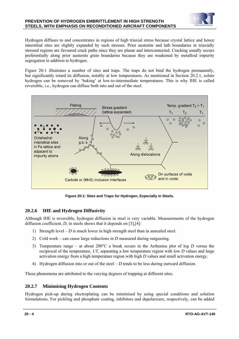
Hydrogen diffuses to and concentrates in regions of high triaxial stress because crystal lattice and hence interstitial sites are slightly expanded by such stresses. Prior austenite and lath boundaries in triaxially stressed regions are favoured crack paths since they are planar and interconnected. Cracking usually occurs preferentially along prior austenite grain boundaries because they are weakened by metalloid impurity segregation in addition to hydrogen.
Figure 20-1 illustrates a number of sites and traps. The traps do not bind the hydrogen permanently, but significantly retard its diffusion, notably at low temperatures. As mentioned in Section 20.2.1, solute hydrogen can be removed by ‘baking’ at low-to-intermediate temperatures. This is why IHE is called reversible, i.e., hydrogen can diffuse both into and out of the steel.
Figure 20-1: Sites and Traps for Hydrogen, Especially in Steels.
20.2.6 IHE and Hydrogen Diffusivity Although IHE is reversible, hydrogen diffusion in steel is very variable. Measurements of the hydrogen diffusion coefficient, D, in steels shows that it depends on [3],[4]:
1) Strength level – D is much lower in high strength steel than in annealed steel.
2) Cold work – can cause large reductions in D measured during outgassing.
3) Temperature range – at about 200°C a break occurs in the Arrhenius plot of log D versus the reciprocal of the temperature, 1/T, separating a low temperature region with low D values and large activation energy from a high temperature region with high D values and small activation energy.
4) Hydrogen diffusion into or out of the steel – D tends to be less during outward diffusion.
These phenomena are attributed to the varying degrees of trapping at different sites.
20.2.7 Minimising Hydrogen Contents Hydrogen pick-up during electroplating can be minimised by using special conditions and solution formulations. For pickling and phosphate coating, inhibitors and depolarizers, respectively, can be added
PREVENTION OF HYDROGEN EMBRITTLEMENT IN HIGH STRENGTH STEELS, WITH EMPHASIS ON RECONDITIONED AIRCRAFT COMPONENTS
RTO-AG-AVT-140 20 - 5
to solutions to minimise hydrogen entry. Selecting a solution for paint-stripping should ensure that the electrode potential of the steel (or steel-plating combination) in the solution lies in the ‘water-stable’ region of the Pourbaix (E – pH) diagram (and preferably well above the H2O + e− → Hads + OH− line). This will minimise or prevent hydrogen ingress. This topic is of major importance in case history 20.5.4, discussed later in this chapter.
Even when hydrogen pick-up is minimised during surface finishing, removing hydrogen that has diffused into steels by subsequent baking at low temperatures (< 205ºC) is generally specified. Recommended baking times and temperatures depend on the finishing process and, for electroplated components, also on:
1) The type, thickness, and porosity of the plate.
2) The strength of the steel.
3) Whether components are sharply notched (or threaded), notably bolts and other fasteners.
Examples of recommended times and temperatures are:
1) For porous cadmium-plated high strength steels: from 23 up to 40 hours at 190ºC.
2) For nickel- and chromium-plated steels: from 3 up to 12 hours at 190ºC.
3) For pickled and cathodically cleaned steels: 3 to 4 hours at 175 – 205ºC.
Baking specifications also indicate that it should be done as soon as possible after plating (typically 4 hours), since excessive delays (> 16 hours) between plating and baking can cause irreversible embrittlement (cracking), e.g., in ultrahigh strength 4340 steel with a tensile strength range of 260 – 280 ksi (1790 – 1930 MPa). Note also that baking at low temperatures can remove hydrogen only from interstitial sites and weak traps such as dislocations and grain boundaries. Hydrogen remaining in deep trap sites such as voids at inclusion-matrix interfaces and between steel surfaces and plating, see Figure 20-1, can diffuse into the steel when sustained tensile stresses are applied, thereby causing some embrittlement.
For some ultrahigh strength steel aircraft components electroplating is replaced by vapour deposition. The coatings are applied by evaporation of the coating species and deposition in low pressure inert gas, both with and without an applied potential. The coating species are typically cadmium or aluminium, and in both cases there is no hydrogen pick-up, although chemical cleaning procedures used prior to such processes may be a source of hydrogen pick-up.
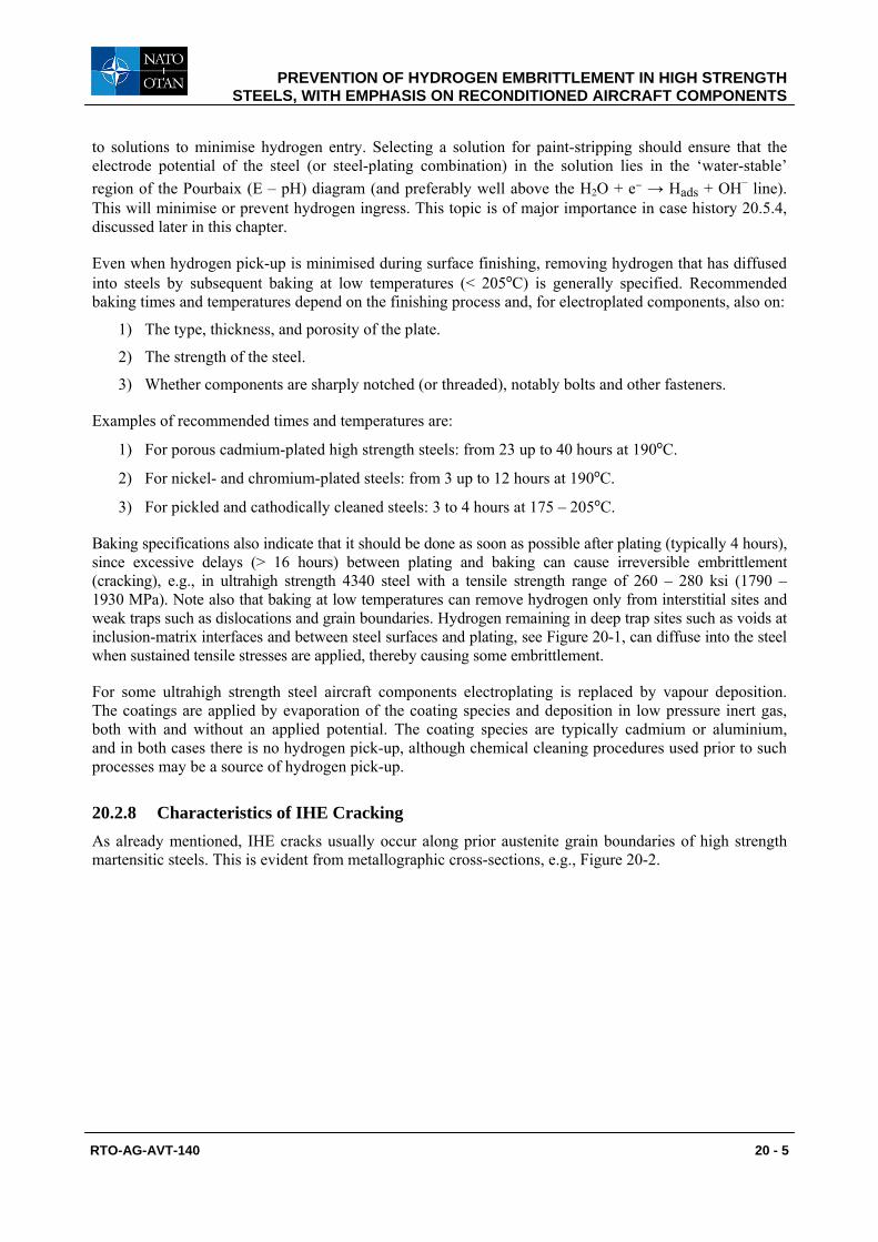
20.2.8 Characteristics of IHE Cracking As already mentioned, IHE cracks usually occur along prior austenite grain boundaries of high strength martensitic steels. This is evident from metallographic cross-sections, e.g., Figure 20-2.
PREVENTION OF HYDROGEN EMBRITTLEMENT IN HIGH STRENGTH STEELS, WITH EMPHASIS ON RECONDITIONED AIRCRAFT COMPONENTS
20 - 6 RTO-AG-AVT-140
Figure 20-2: Characteristics of Internal Hydrogen Embrittlement (IHE) in High Strength Steels – I.
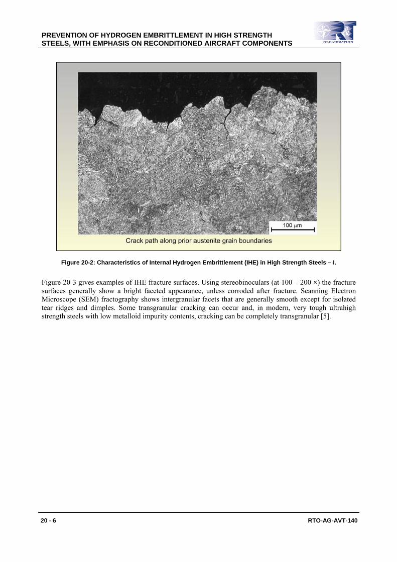
Figure 20-3 gives examples of IHE fracture surfaces. Using stereobinoculars (at 100 – 200 ×) the fracture surfaces generally show a bright faceted appearance, unless corroded after fracture. Scanning Electron Microscope (SEM) fractography shows intergranular facets that are generally smooth except for isolated tear ridges and dimples. Some transgranular cracking can occur and, in modern, very tough ultrahigh strength steels with low metalloid impurity contents, cracking can be completely transgranular [5].
PREVENTION OF HYDROGEN EMBRITTLEMENT IN HIGH STRENGTH STEELS, WITH EMPHASIS ON RECONDITIONED AIRCRAFT COMPONENTS
RTO-AG-AVT-140 20 - 7
Figure 20-3: Characteristics of Internal Hydrogen Embrittlement (IHE) in High Strength Steels – II.
20.3 DISTINGUISHING IHE FROM OTHER INTERGRANULAR FRACTURE MODES
Other fracture modes that can produce cracking along prior austenite grain boundaries in high strength steels include:
1) Overload (fast) fracture in temper-embrittled steels.
2) Stress Corrosion Cracking (SCC).
3) Corrosion Fatigue (CF).
4) Liquid-Metal Embrittlement (LME).
5) Solid-Metal Induced Embrittlement (SMIE).
6) Quench Cracking.
Failures can sometimes involve several of these fracture modes, e.g., sub-critical cracking by intergranular IHE followed by intergranular overload fracture. Distinguishing between these fracture modes can be difficult, but some guidelines are:
• IHE fractures are generally bright and uncorroded, as mentioned in Section 20.2.8, but corrosion can sometimes occur after cracking. For completely fractured parts, exposure to high humidity air or aqueous environments can cause rusting (reddish hydrated ferric oxides). If components are only partly cracked by IHE, exposure of cracks to aqueous environments could produce black (magnetite) oxide films on crack surfaces.
• SCC and CF fractures produced in aqueous environments are usually covered by black oxide films or occasionally show interference colours (due to very thin oxide films produced in oxygen-depleted solutions within cracks): a probable CF fracture is shown in case history 20.5.3 later in
PREVENTION OF HYDROGEN EMBRITTLEMENT IN HIGH STRENGTH STEELS, WITH EMPHASIS ON RECONDITIONED AIRCRAFT COMPONENTS
20 - 8 RTO-AG-AVT-140
this chapter. However, SCC of ultrahigh strength steels can occur in moist air environments and the fracture surfaces may be bright and relatively uncorroded, closely resembling those produced by IHE.
• CF sometimes results in faint progression markings or striations on intergranular facets, but corrosion products may often obscure these details.
• SCC and CF often initiate from corrosion pits, whereas IHE initiates just beneath surfaces. However, IHE initiation in high strength steels may be so close to the surface that it appears to have begun there.
• LME usually results in thick films of the embrittling metal on fracture surfaces and within secondary cracks. These films are readily observed.
• SMIE results in thin films of the embrittling metal on fracture surfaces, but these films may not be obvious.
Examples of failures by these various modes, and more detailed discussion distinguishing between intergranular fracture modes can be found elsewhere [6]. Be that as it may, it should be evident from the foregoing discussion that much care and expertise are required when interpreting the fractographic evidence from a high strength steel component suspected to have failed by IHE.
20.4 TESTING PROCEDURES FOR ASSESSING THE DEGREE OF IHE
The OEMs usually specify that each batch of high strength steel components to be electroplated (mainly by cadmium) be accompanied by notched tensile specimens of the same material. These specimens are subsequently proof tested to verify that the components have been correctly processed. However, successful proof testing of specimens is not necessarily a guarantee that the batch of components has not been damaged by IHE, see Section 20.4.4.
The commonly accepted proof testing standard for IHE is ASTM F 519-06 [7]. In the first instance this standard is intended only for one type of high strength steel, see Section 20.4.1. There is also an ASTM standard to measure the threshold stresses and stress intensity factors for IHE in any high strength steel [8]. This standard is more of an R&D tool, though it could be used for proof testing, and is referred to in ASTM F 519-06, see Section 20.4.1. In addition, there is a military aircraft proof testing standard, NASM1312-5 [9], for externally-threaded fasteners made from any material, see Section 20.4.2.
There is also a test method based on slow Strain Rate Dynamic Tensile (SSRT) testing of ASTM F 519-06 tensile-type specimens. This test method is discussed in Section 20.4.6, and has shown promise as a relatively rapid way of assessing IHE. Two examples of the use of SSRT testing are given in case histories 20.5.5 and 20.5.6.
20.4.1 ASTM Standard Test Method F 519-06
This test method has been developed specifically to evaluate plating processes and service environments1 with respect to their potential for hydrogen embrittlement of AISI 4340 steel with a tensile strength range of 260 – 280 ksi (1790 – 1930 MPa) corresponding to Rockwell C hardnesses of 51 – 53 HRC.
20.4.1.1 Evaluating Plating Process IHE
Three types of tests are specified for the plated and baked AISI 4340 steel:
1 Defined as chemicals that contact bare or plated/coated steel components during manufacturing, overhaul and service life.
PREVENTION OF HYDROGEN EMBRITTLEMENT IN HIGH STRENGTH STEELS, WITH EMPHASIS ON RECONDITIONED AIRCRAFT COMPONENTS
RTO-AG-AVT-140 20 - 9
1) Sustained Load Tests (SLT), Notched Specimens: These must exceed 200 hours at a sustained load of 75% of the notched fracture stress.
2) Sustained Load Tests (SLT), Smooth Ring Specimens: These must exceed 200 hours at a sustained load of 92% of the tensile ultimate strength.
3) Incremental Step-Load (ISL) Tests: An accelerated incrementally increasing step-load test may be used as an alternative to SLT, if approved by the appropriate engineering authority, see Section 20.4.5.
20.4.1.2 Evaluating Service Environment IHE
These tests are for bare or plated/coated AISI 4340 steel. Different types of tests are specified for aggressive chemicals (e.g., temper etchants) or passive chemicals (cleaners and paint strippers):
1) Aggressive Chemicals – Notched and smooth specimens are immersed at 45% of the notched fracture stress for the exposure time of the relevant service specification. Then the specimens and test fixtures are neutralized per the relevant service specification, rinsed and dried. The load is then increased to 75% of the notched fracture strength for notched specimens and 92% of the tensile ultimate strength for smooth specimens. The environment is considered non-embrittling if no failures occur within 200 hours.
2) Passive Chemicals – Notched specimens are immersed at 45% or 65% of the notched fracture stress, depending on specimen type, for 150 hours. Smooth specimens are immersed at 80% of the 0.2% yield strength for 150 hours. A passive environment is considered non-embrittling if no failures occur within 150 hours.
20.4.2 National Aerospace Standard NASM1312-5 This test method applies to all types of externally threaded fasteners, made from any material, and which may be subject to any type of embrittlement. The fasteners to be tested are assembled in “test units”, which are custom-made fixtures. Loading may be applied in several ways, provided that the induced load on the fastener is 75 – 80 % of the minimum ultimate tensile strength [notched fracture stress] of the fastener. The loads are applied at room temperature and maintained for the time specified by the procurement document or product specification.
For evaluating IHE of high strength steels the test duration will most probably be 200 hours, as per ASTM F 519-06. There is an important reason for this, discussed in Section 20.4.3.
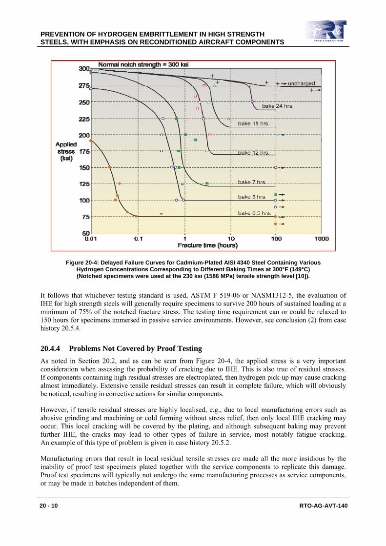
20.4.3 Proof Test Duration: The “No Failure in 200 Hours” Criterion For verifying correct processing to avoid IHE, ASTM Standard F 519-06 specifies that high strength steel specimens should not fail within 200 hours at a sustained load of 75% of the notched fracture stress after plating and baking or exposure to aggressive service environments. The “no failure in 200 hours” criterion was obtained from the classic work of Troiano [10]. Figure 20-4 shows Troiano’s data for delayed failure of sharp-notched specimens of high strength AISI 4340 steel after cadmium plating and baking for various times. There are two main points to note here:
1) There is obviously a strong effect of baking time on the plateau failure stress level, called by Troiano the static fatigue limit.
2) 75% of the notched fracture stress corresponds to an applied stress of 225 ksi. From Figure 20-4 and the shapes of the delayed failure curves it may be deduced that unless baking has been done for the usual standard time of 24 hours, failure at this stress level should occur well within 200 hours.
PREVENTION OF HYDROGEN EMBRITTLEMENT IN HIGH STRENGTH STEELS, WITH EMPHASIS ON RECONDITIONED AIRCRAFT COMPONENTS
20 - 10 RTO-AG-AVT-140
Figure 20-4: Delayed Failure Curves for Cadmium-Plated AISI 4340 Steel Containing Various Hydrogen Concentrations Corresponding to Different Baking Times at 300°F (149°C) (Notched specimens were used at the 230 ksi (1586 MPa) tensile strength level [10]).
It follows that whichever testing standard is used, ASTM F 519-06 or NASM1312-5, the evaluation of IHE for high strength steels will generally require specimens to survive 200 hours of sustained loading at a minimum of 75% of the notched fracture stress. The testing time requirement can or could be relaxed to 150 hours for specimens immersed in passive service environments. However, see conclusion (2) from case history 20.5.4.
20.4.4 Problems Not Covered by Proof Testing As noted in Section 20.2, and as can be seen from Figure 20-4, the applied stress is a very important consideration when assessing the probability of cracking due to IHE. This is also true of residual stresses. If components containing high residual stresses are electroplated, then hydrogen pick-up may cause cracking almost immediately. Extensive tensile residual stresses can result in complete failure, which will obviously be noticed, resulting in corrective actions for similar components.
However, if tensile residual stresses are highly localised, e.g., due to local manufacturing errors such as abusive grinding and machining or cold forming without stress relief, then only local IHE cracking may occur. This local cracking will be covered by the plating, and although subsequent baking may prevent further IHE, the cracks may lead to other types of failure in service, most notably fatigue cracking. An example of this type of problem is given in case history 20.5.2.
Manufacturing errors that result in local residual tensile stresses are made all the more insidious by the inability of proof test specimens plated together with the service components to replicate this damage. Proof test specimens will typically not undergo the same manufacturing processes as service components, or may be made in batches independent of them.
PREVENTION OF HYDROGEN EMBRITTLEMENT IN HIGH STRENGTH STEELS, WITH EMPHASIS ON RECONDITIONED AIRCRAFT COMPONENTS
RTO-AG-AVT-140 20 - 11
Some of the above points may be equally applicable to the two tests described in the following sections (20.4.5 and 20.4.6).
20.4.5 Incremental Step Load (ISL) Tests Incremental Step Load (ISL) testing is an accelerated test method designed to measure the IHE threshold stress within one week. The tests are standard dynamic tests specified in ASTM Standard F1624-06 [8]. This standard uses fracture mechanics specimens (similar to some of the types proposed in ASTM F519-06) loaded either in tension or four-point bending. The specimens may be manufactured from various steels being assessed for IHE.
The recommended loading procedure consists of 15 steps of 5% notched fracture stress per hour up to 75% of the notched fracture stress, and then steps of 5% notched fracture stress per 2 hours until failure. The threshold stress for IHE is determined by monitoring the loads during the hold times between load increments: if the applied load decreases during a hold period, then cracking is assumed to have occurred, and the load initially applied during this hold period is assumed to correspond to the threshold stress.
Notes:
1) Several tests are required to establish the maximum unembrittled fracture load for the specimen geometry being ISL-tested.
2) Although there is no established equivalence between the ISL and SLT test methods, it is assumed that ISL-tested specimens that sustain 90% of the notched fracture stress for 2 hours can be considered unembrittled.
Besides the above-recommended loading procedure, ASTM F1624-06 suggests a number of alternative loading protocols. These can have durations varying from 8 to 90 hours. Furthermore, the ISL test method allows flexibility in:
a) Choosing the most appropriate number of steps and hold times; and
b) Deciding what is a sufficient number of tests to determine the threshold stress.
The very flexibility of this test method could detract from confidence in using it, but it is nevertheless capable of giving excellent results.
20.4.6 Slow Strain Rate Tensile (SSRT) Tests The Slow Strain Rate Tensile (SSRT) test method differs from ISL testing in three important respects:
1) Loading is continuous.
2) Only round bar notched tensile SAE E4340 specimens are used. These are similar in design to those in ASTM Standard F519-06. The steel is heat-treated to the 260 – 280 ksi level (1790 – 1930 MPa).
3) The cross-head displacement rate is much less than that during step loading in ISL tests. The very low displacement rate allows sufficient time for the continuous migration of absorbed atomic hydrogen to the triaxial stress field ahead of the notch, rather than only during the hold times in ISL tests.
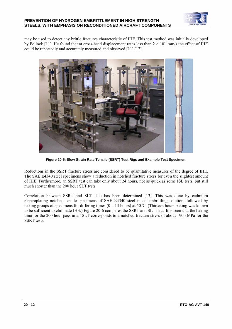
Figure 20-5 shows some SSRT test rigs and the specimen configuration. The SSRT tests are carried out to failure of the specimens and provide the notched tensile strengths or fracture stresses. These data are then compared with those of identical specimens known to be unembrittled. In addition, SEM fractography
PREVENTION OF HYDROGEN EMBRITTLEMENT IN HIGH STRENGTH STEELS, WITH EMPHASIS ON RECONDITIONED AIRCRAFT COMPONENTS
20 - 12 RTO-AG-AVT-140
may be used to detect any brittle fractures characteristic of IHE. This test method was initially developed by Pollock [11]. He found that at cross-head displacement rates less than 2 × 10⁻⁴ mm/s the effect of IHE could be repeatedly and accurately measured and observed [11],[12].
Figure 20-5: Slow Strain Rate Tensile (SSRT) Test Rigs and Example Test Specimen.
Reductions in the SSRT fracture stress are considered to be quantitative measures of the degree of IHE. The SAE E4340 steel specimens show a reduction in notched fracture stress for even the slightest amount of IHE. Furthermore, an SSRT test can take only about 24 hours, not as quick as some ISL tests, but still much shorter than the 200 hour SLT tests.
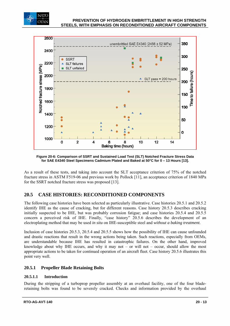
Correlation between SSRT and SLT data has been determined [13]. This was done by cadmium electroplating notched tensile specimens of SAE E4340 steel in an embrittling solution, followed by baking groups of specimens for differing times (0 – 13 hours) at 50°C. (Thirteen hours baking was known to be sufficient to eliminate IHE.) Figure 20-6 compares the SSRT and SLT data. It is seen that the baking time for the 200 hour pass in an SLT corresponds to a notched fracture stress of about 1900 MPa for the SSRT tests.
PREVENTION OF HYDROGEN EMBRITTLEMENT IN HIGH STRENGTH STEELS, WITH EMPHASIS ON RECONDITIONED AIRCRAFT COMPONENTS
RTO-AG-AVT-140 20 - 13
Figure 20-6: Comparison of SSRT and Sustained Load Test (SLT) Notched Fracture Stress Data for SAE E4340 Steel Specimens Cadmium Plated and Baked at 50°C for 0 – 13 Hours [13].
As a result of these tests, and taking into account the SLT acceptance criterion of 75% of the notched fracture stress in ASTM F519-06 and previous work by Pollock [11], an acceptance criterion of 1840 MPa for the SSRT notched fracture stress was proposed [13].
20.5 CASE HISTORIES: RECONDITIONED COMPONENTS The following case histories have been selected as particularly illustrative. Case histories 20.5.1 and 20.5.2 identify IHE as the cause of cracking, but for different reasons. Case history 20.5.3 describes cracking initially suspected to be IHE, but was probably corrosion fatigue; and case histories 20.5.4 and 20.5.5 concern a perceived risk of IHE. Finally, “case history” 20.5.6 describes the development of an electroplating method that may be used in situ on IHE-susceptible steel and without a baking treatment.
Inclusion of case histories 20.5.3, 20.5.4 and 20.5.5 shows how the possibility of IHE can cause unfounded and drastic reactions that result in the wrong actions being taken. Such reactions, especially from OEMs, are understandable because IHE has resulted in catastrophic failures. On the other hand, improved knowledge about why IHE occurs, and why it may not – or will not – occur, should allow the most appropriate actions to be taken for continued operation of an aircraft fleet. Case history 20.5.6 illustrates this point very well.
20.5.1 Propeller Blade Retaining Bolts
20.5.1.1 Introduction During the stripping of a turboprop propeller assembly at an overhaul facility, one of the four blade-retaining bolts was found to be severely cracked. Checks and information provided by the overhaul
PREVENTION OF HYDROGEN EMBRITTLEMENT IN HIGH STRENGTH STEELS, WITH EMPHASIS ON RECONDITIONED AIRCRAFT COMPONENTS
20 - 14 RTO-AG-AVT-140
contractor showed that this bolt was one of a batch of eight that had been previously overhauled at the same time. All eight bolts, one cracked and seven uncracked, were investigated at the Defence Science and Technology Organisation2 in Melbourne, Australia. This investigation [14] comprised the following steps:
1) Optical examination for corrosion and mechanical damage.
2) Optical and Scanning Electron Microscope (SEM) fractography of the cracked bolt.
3) Microstructure, hardness and chemical composition of the bolt material.
4) Auger Electron Spectroscopy (AES) of a fresh fracture surface from a test specimen.
5) Slow Strain Rate Tensile (SSRT) tests and subsequent hydrogen analysis.
The bolts were specified to have been made from S99 low alloy steel heat-treated to a tensile strength of about 1380 MPa.
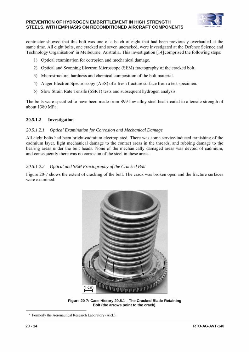
Figure 20-7: Case History 20.5.1 – The Cracked Blade-Retaining Bolt (the arrows point to the crack).
2 Formerly the Aeronautical Research Laboratory (ARL).
20.5.1.2 Investigation
20.5.1.2.1 Optical Examination for Corrosion and Mechanical Damage
All eight bolts had been bright-cadmium electroplated. There was some service-induced tarnishing of the cadmium layer, light mechanical damage to the contact areas in the threads, and rubbing damage to the bearing areas under the bolt heads. None of the mechanically damaged areas was devoid of cadmium, and consequently there was no corrosion of the steel in these areas.
20.5.1.2.2 Optical and SEM Fractography of the Cracked Bolt
Figure 20-7 shows the extent of cracking of the bolt. The crack was broken open and the fracture surfaces were examined.
PREVENTION OF HYDROGEN EMBRITTLEMENT IN HIGH STRENGTH STEELS, WITH EMPHASIS ON RECONDITIONED AIRCRAFT COMPONENTS
RTO-AG-AVT-140 20 - 15
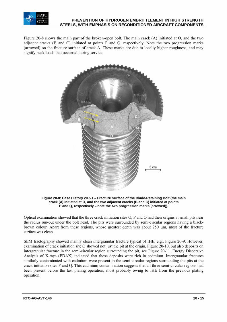
Figure 20-8 shows the main part of the broken-open bolt. The main crack (A) initiated at O, and the two adjacent cracks (B and C) initiated at points P and Q, respectively. Note the two progression marks (arrowed) on the fracture surface of crack A. These marks are due to locally higher roughness, and may signify peak loads that occurred during service.
Figure 20-8: Case History 20.5.1 – Fracture Surface of the Blade-Retaining Bolt (the main crack (A) initiated at O, and the two adjacent cracks (B and C) initiated at points
P and Q, respectively – note the two progression marks (arrowed)).
Optical examination showed that the three crack initiation sites O, P and Q had their origins at small pits near the radius run-out under the bolt head. The pits were surrounded by semi-circular regions having a black-brown colour. Apart from these regions, whose greatest depth was about 250 μm, most of the fracture surface was clean.
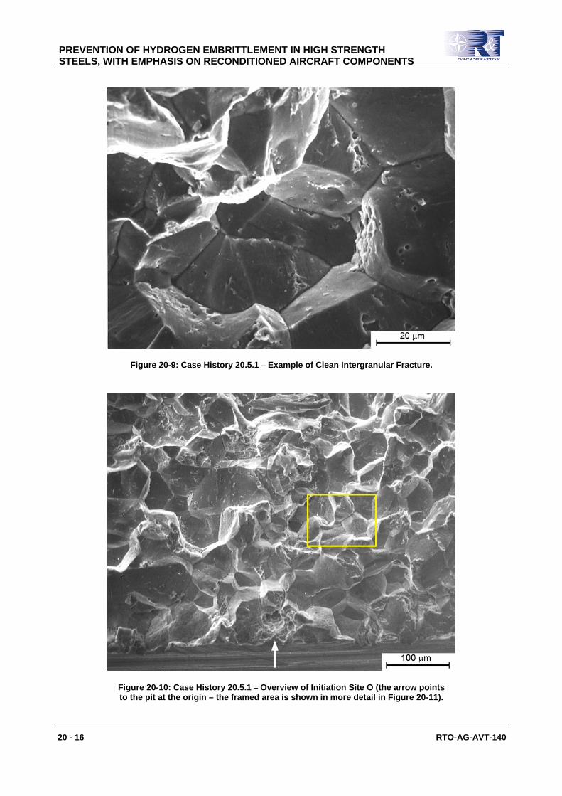
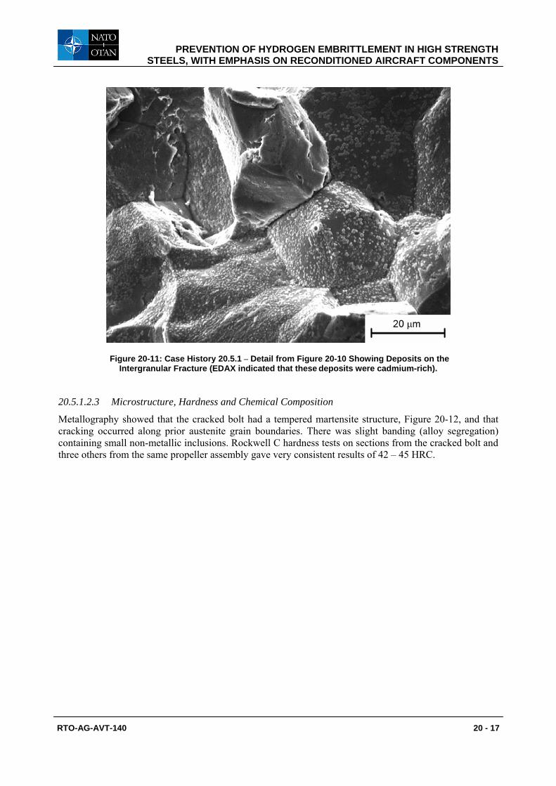
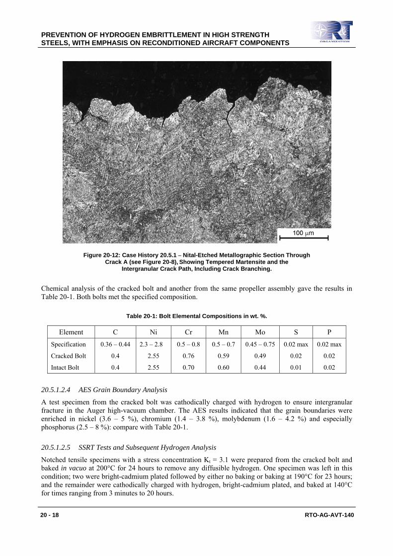
SEM fractography showed mainly clean intergranular fracture typical of IHE, e.g., Figure 20-9. However, examination of crack initiation site O showed not just the pit at the origin, Figure 20-10, but also deposits on intergranular fracture in the semi-circular region surrounding the pit, see Figure 20-11. Energy Dispersive Analysis of X-rays (EDAX) indicated that these deposits were rich in cadmium. Intergranular fractures similarly contaminated with cadmium were present in the semi-circular regions surrounding the pits at the crack initiation sites P and Q. This cadmium contamination suggests that all three semi-circular regions had been present before the last plating operation, most probably owing to IHE from the previous plating operation.
PREVENTION OF HYDROGEN EMBRITTLEMENT IN HIGH STRENGTH STEELS, WITH EMPHASIS ON RECONDITIONED AIRCRAFT COMPONENTS
20 - 16 RTO-AG-AVT-140
Figure 20-9: Case History 20.5.1 – Example of Clean Intergranular Fracture.
Figure 20-10: Case History 20.5.1 – Overview of Initiation Site O (the arrow points to the pit at the origin – the framed area is shown in more detail in Figure 20-11).
PREVENTION OF HYDROGEN EMBRITTLEMENT IN HIGH STRENGTH STEELS, WITH EMPHASIS ON RECONDITIONED AIRCRAFT COMPONENTS
RTO-AG-AVT-140 20 - 17
Figure 20-11: Case History 20.5.1 – Detail from Figure 20-10 Showing Deposits on the Intergranular Fracture (EDAX indicated that these deposits were cadmium-rich).
20.5.1.2.3 Microstructure, Hardness and Chemical Composition
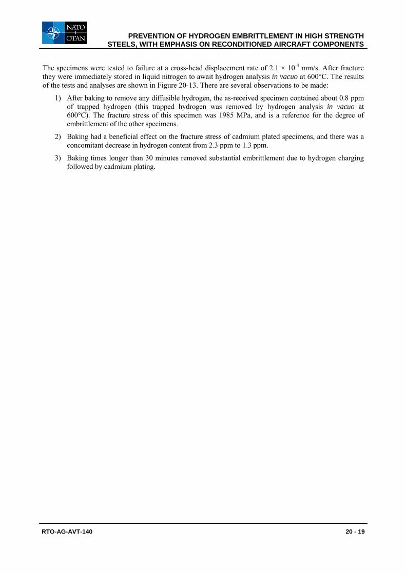
Metallography showed that the cracked bolt had a tempered martensite structure, Figure 20-12, and that cracking occurred along prior austenite grain boundaries. There was slight banding (alloy segregation) containing small non-metallic inclusions. Rockwell C hardness tests on sections from the cracked bolt and three others from the same propeller assembly gave very consistent results of 42 – 45 HRC.
PREVENTION OF HYDROGEN EMBRITTLEMENT IN HIGH STRENGTH STEELS, WITH EMPHASIS ON RECONDITIONED AIRCRAFT COMPONENTS
20 - 18 RTO-AG-AVT-140
Figure 20-12: Case History 20.5.1 – Nital-Etched Metallographic Section Through Crack A (see Figure 20-8), Showing Tempered Martensite and the
Intergranular Crack Path, Including Crack Branching.
Chemical analysis of the cracked bolt and another from the same propeller assembly gave the results in Table 20-1. Both bolts met the specified composition.
Table 20-1: Bolt Elemental Compositions in wt. %.
Element C Ni Cr Mn Mo S P
Specification
Cracked Bolt
Intact Bolt
0.36 – 0.44
0.4
0.4
2.3 – 2.8
2.55
2.55
0.5 – 0.8
0.76
0.70
0.5 – 0.7
0.59
0.60
0.45 – 0.75
0.49
0.44
0.02 max
0.02
0.01
0.02 max
0.02
0.02
20.5.1.2.4 AES Grain Boundary Analysis
A test specimen from the cracked bolt was cathodically charged with hydrogen to ensure intergranular fracture in the Auger high-vacuum chamber. The AES results indicated that the grain boundaries were enriched in nickel (3.6 – 5 %), chromium (1.4 – 3.8 %), molybdenum (1.6 – 4.2 %) and especially phosphorus (2.5 – 8 %): compare with Table 20-1.
20.5.1.2.5 SSRT Tests and Subsequent Hydrogen Analysis
Notched tensile specimens with a stress concentration Kt = 3.1 were prepared from the cracked bolt and baked in vacuo at 200°C for 24 hours to remove any diffusible hydrogen. One specimen was left in this condition; two were bright-cadmium plated followed by either no baking or baking at 190°C for 23 hours; and the remainder were cathodically charged with hydrogen, bright-cadmium plated, and baked at 140°C for times ranging from 3 minutes to 20 hours.
PREVENTION OF HYDROGEN EMBRITTLEMENT IN HIGH STRENGTH STEELS, WITH EMPHASIS ON RECONDITIONED AIRCRAFT COMPONENTS
RTO-AG-AVT-140 20 - 19
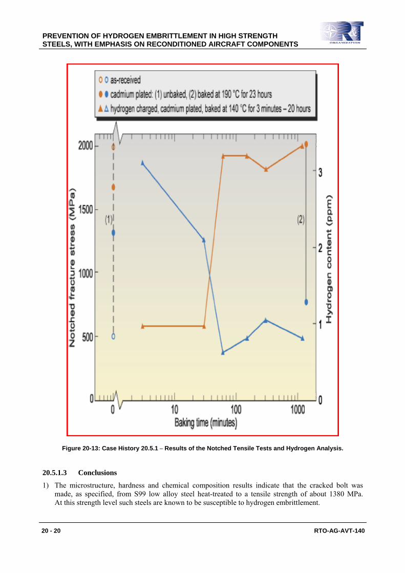
The specimens were tested to failure at a cross-head displacement rate of 2.1 × 10⁻⁴ mm/s. After fracture they were immediately stored in liquid nitrogen to await hydrogen analysis in vacuo at 600°C. The results of the tests and analyses are shown in Figure 20-13. There are several observations to be made:
1) After baking to remove any diffusible hydrogen, the as-received specimen contained about 0.8 ppm of trapped hydrogen (this trapped hydrogen was removed by hydrogen analysis in vacuo at 600°C). The fracture stress of this specimen was 1985 MPa, and is a reference for the degree of embrittlement of the other specimens.
2) Baking had a beneficial effect on the fracture stress of cadmium plated specimens, and there was a concomitant decrease in hydrogen content from 2.3 ppm to 1.3 ppm.
3) Baking times longer than 30 minutes removed substantial embrittlement due to hydrogen charging followed by cadmium plating.
PREVENTION OF HYDROGEN EMBRITTLEMENT IN HIGH STRENGTH STEELS, WITH EMPHASIS ON RECONDITIONED AIRCRAFT COMPONENTS
20 - 20 RTO-AG-AVT-140
Figure 20-13: Case History 20.5.1 – Results of the Notched Tensile Tests and Hydrogen Analysis.
20.5.1.3 Conclusions
1) The microstructure, hardness and chemical composition results indicate that the cracked bolt was made, as specified, from S99 low alloy steel heat-treated to a tensile strength of about 1380 MPa. At this strength level such steels are known to be susceptible to hydrogen embrittlement.

PREVENTION OF HYDROGEN EMBRITTLEMENT IN HIGH STRENGTH STEELS, WITH EMPHASIS ON RECONDITIONED AIRCRAFT COMPONENTS
RTO-AG-AVT-140 20 - 21
2) During final processing (heat treatment) of the bolt there was significant segregation of phosphorus to prior austenite grain boundaries (2.5 – 8 %) compared to 0.02% in the bulk material. The phosphorus segregation would have made the bolt more susceptible to hydrogen embrittlement for a given strength level and (diffusible) hydrogen content.
3) At some time in the bolt’s life it sustained local damage due to pitting corrosion.
4) Before the previous overhaul, small semi-circular regions of intergranular fracture spread from the three corrosion pits near the radius run-out under the bolt head. These intergranular fractures were most probably due to IHE from the previous plating operation.
5) During the previous overhaul the bolt underwent bright-cadmium electroplating, thereby absorbing hydrogen that was not entirely removed by baking, possibly because the baking process was inadequate. The electroplating also resulted in cadmium deposition on the small semi-circular regions of intergranular fracture.
6) After the bolt was fitted into the propeller assembly, clean intergranular fracture typical of IHE spread from the cadmium-contaminated small semi-circular regions of intergranular fracture.
7) By the time of the last overhaul the IHE cracking was extensive, resulting in its detection during stripping of the propeller assembly.
20.5.1.4 Remedial Actions
The initial remedial action was to recover the remaining batch of bolts, since replacement bolts were not immediately available. This recovery required stripping the cadmium and inspecting the radius regions of the bolts for pits and cracks using a high resolution magnetic particle method of Non-Destructive Inspection (NDI). If no pits or cracks were detected the bolts were re-plated, baked for an appropriate time (which was increased over the original baking time) and re-issued for service.
In parallel with this recovery procedure, the static and fatigue implications of cracks being present just below the NDI limit were assessed. It was concluded that such cracks would be very unlikely to cause failure before the next overhaul.
Since some doubt remained about the other bolts in the fleet, it was decided to inspect them with the same NDI method during their next overhaul; and as a further precaution, this next overhaul period was reduced to the minimum allowable by the fleet commitments.
20.5.2 Main Undercarriage Half-Fork Assemblies
20.5.2.1 Introduction
Following an incident involving a tactical aircraft main undercarriage half-fork assembly, an operator was advised to inspect the fleet for certain types of cracking in the hard-chromium electroplated sections of the assemblies. Numerous assemblies were found to be cracked in a potentially serious manner. Destructive examination of one of the “worst” cases showed that cracking had penetrated beyond the chromium plate and into the steel substrate. At this point the operator requested the DSTO to investigate another “worst” case. This investigation [15] comprised the following steps:
• Dye penetrant NDI of the as-received assembly.
• Chemical stripping of most of the chromium plate, dye penetrant NDI and etching of selected areas of the steel that had been below the chromium plated section.
• Metallographic cross-sections of non-stripped areas.
• Fractography of broken-open cracks.
PREVENTION OF HYDROGEN EMBRITTLEMENT IN HIGH STRENGTH STEELS, WITH EMPHASIS ON RECONDITIONED AIRCRAFT COMPONENTS
20 - 22 RTO-AG-AVT-140
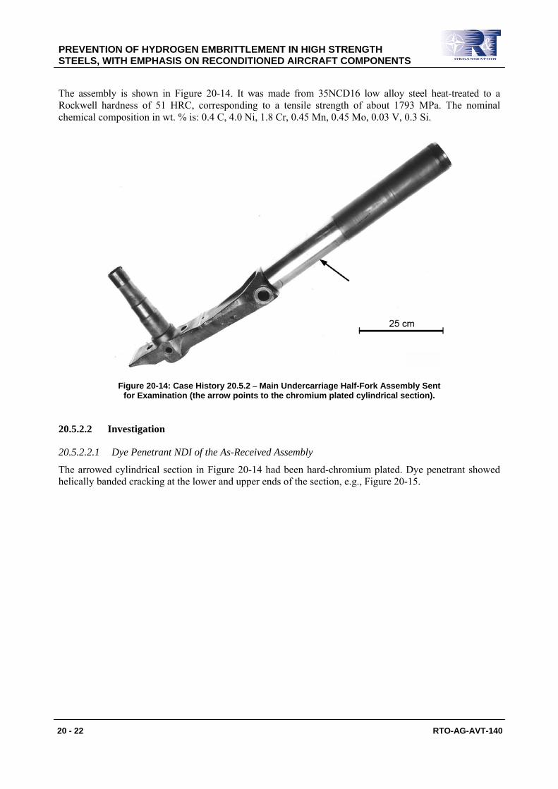
The assembly is shown in Figure 20-14. It was made from 35NCD16 low alloy steel heat-treated to a Rockwell hardness of 51 HRC, corresponding to a tensile strength of about 1793 MPa. The nominal chemical composition in wt. % is: 0.4 C, 4.0 Ni, 1.8 Cr, 0.45 Mn, 0.45 Mo, 0.03 V, 0.3 Si.
Figure 20-14: Case History 20.5.2 – Main Undercarriage Half-Fork Assembly Sent for Examination (the arrow points to the chromium plated cylindrical section).
20.5.2.2 Investigation
20.5.2.2.1 Dye Penetrant NDI of the As-Received Assembly
The arrowed cylindrical section in Figure 20-14 had been hard-chromium plated. Dye penetrant showed helically banded cracking at the lower and upper ends of the section, e.g., Figure 20-15.
PREVENTION OF HYDROGEN EMBRITTLEMENT IN HIGH STRENGTH STEELS, WITH EMPHASIS ON RECONDITIONED AIRCRAFT COMPONENTS
RTO-AG-AVT-140 20 - 23
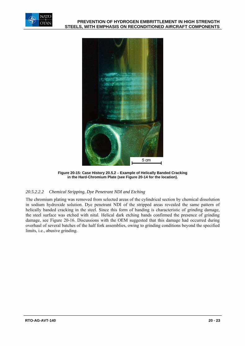
Figure 20-15: Case History 20.5.2 – Example of Helically Banded Cracking in the Hard-Chromium Plate (see Figure 20-14 for the location).
20.5.2.2.2 Chemical Stripping, Dye Penetrant NDI and Etching
The chromium plating was removed from selected areas of the cylindrical section by chemical dissolution in sodium hydroxide solution. Dye penetrant NDI of the stripped areas revealed the same pattern of helically banded cracking in the steel. Since this form of banding is characteristic of grinding damage, the steel surface was etched with nital. Helical dark etching bands confirmed the presence of grinding damage, see Figure 20-16. Discussions with the OEM suggested that this damage had occurred during overhaul of several batches of the half fork assemblies, owing to grinding conditions beyond the specified limits, i.e., abusive grinding.
PREVENTION OF HYDROGEN EMBRITTLEMENT IN HIGH STRENGTH STEELS, WITH EMPHASIS ON RECONDITIONED AIRCRAFT COMPONENTS
20 - 24 RTO-AG-AVT-140
Figure 20-16: Case History 20.5.2 – Helical Dark Etching Bands Indicating Grinding Damage of the Steel Surface of the Lower Part of the Cylindrical Section (note the
irregular areas with retained hard-chromium plate).
20.5.2.2.3 Metallography
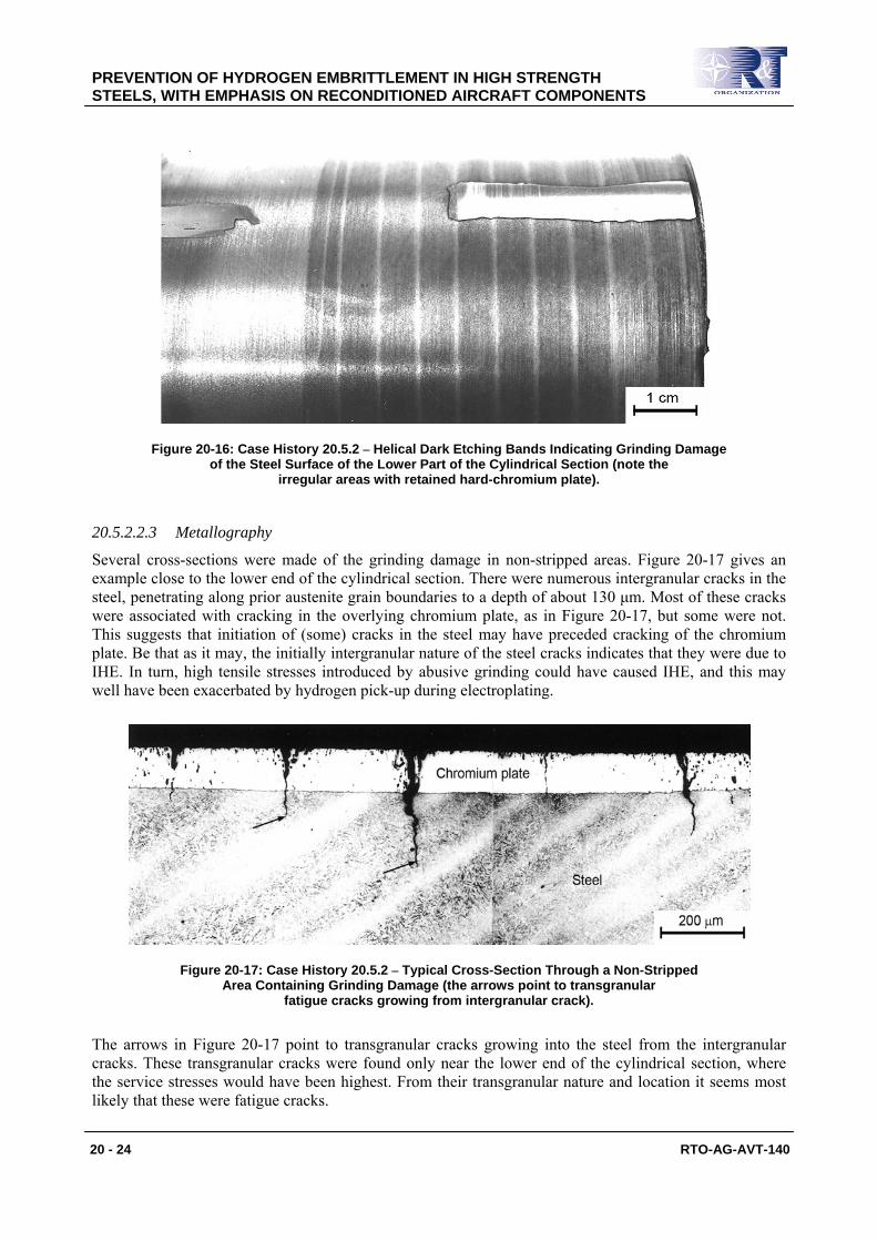
Several cross-sections were made of the grinding damage in non-stripped areas. Figure 20-17 gives an example close to the lower end of the cylindrical section. There were numerous intergranular cracks in the steel, penetrating along prior austenite grain boundaries to a depth of about 130 μm. Most of these cracks were associated with cracking in the overlying chromium plate, as in Figure 20-17, but some were not. This suggests that initiation of (some) cracks in the steel may have preceded cracking of the chromium plate. Be that as it may, the initially intergranular nature of the steel cracks indicates that they were due to IHE. In turn, high tensile stresses introduced by abusive grinding could have caused IHE, and this may well have been exacerbated by hydrogen pick-up during electroplating.
Figure 20-17: Case History 20.5.2 – Typical Cross-Section Through a Non-Stripped Area Containing Grinding Damage (the arrows point to transgranular
fatigue cracks growing from intergranular crack).
The arrows in Figure 20-17 point to transgranular cracks growing into the steel from the intergranular cracks. These transgranular cracks were found only near the lower end of the cylindrical section, where the service stresses would have been highest. From their transgranular nature and location it seems most likely that these were fatigue cracks.
PREVENTION OF HYDROGEN EMBRITTLEMENT IN HIGH STRENGTH STEELS, WITH EMPHASIS ON RECONDITIONED AIRCRAFT COMPONENTS
RTO-AG-AVT-140 20 - 25
20.5.2.2.4 Fractography
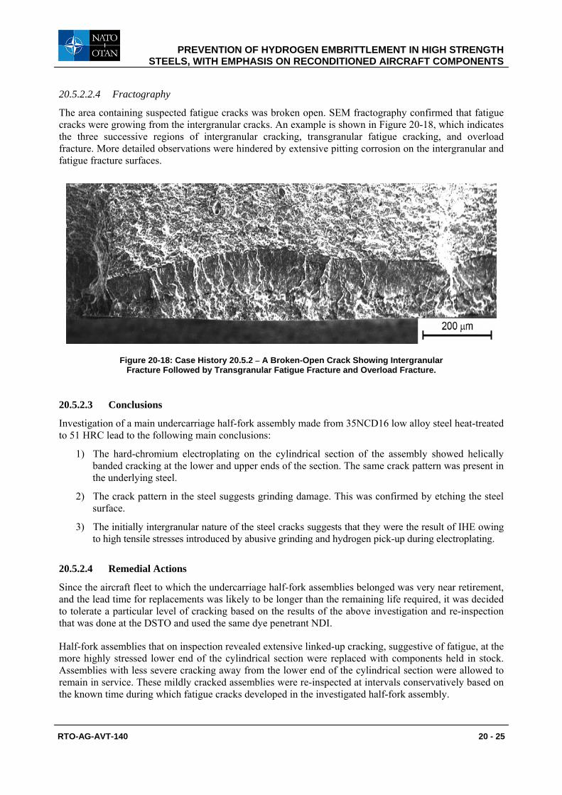
The area containing suspected fatigue cracks was broken open. SEM fractography confirmed that fatigue cracks were growing from the intergranular cracks. An example is shown in Figure 20-18, which indicates the three successive regions of intergranular cracking, transgranular fatigue cracking, and overload fracture. More detailed observations were hindered by extensive pitting corrosion on the intergranular and fatigue fracture surfaces.
Figure 20-18: Case History 20.5.2 – A Broken-Open Crack Showing Intergranular Fracture Followed by Transgranular Fatigue Fracture and Overload Fracture.
20.5.2.3 Conclusions
Investigation of a main undercarriage half-fork assembly made from 35NCD16 low alloy steel heat-treated to 51 HRC lead to the following main conclusions:
1) The hard-chromium electroplating on the cylindrical section of the assembly showed helically banded cracking at the lower and upper ends of the section. The same crack pattern was present in the underlying steel.
2) The crack pattern in the steel suggests grinding damage. This was confirmed by etching the steel surface.
3) The initially intergranular nature of the steel cracks suggests that they were the result of IHE owing to high tensile stresses introduced by abusive grinding and hydrogen pick-up during electroplating.
20.5.2.4 Remedial Actions
Since the aircraft fleet to which the undercarriage half-fork assemblies belonged was very near retirement, and the lead time for replacements was likely to be longer than the remaining life required, it was decided to tolerate a particular level of cracking based on the results of the above investigation and re-inspection that was done at the DSTO and used the same dye penetrant NDI.
Half-fork assemblies that on inspection revealed extensive linked-up cracking, suggestive of fatigue, at the more highly stressed lower end of the cylindrical section were replaced with components held in stock. Assemblies with less severe cracking away from the lower end of the cylindrical section were allowed to remain in service. These mildly cracked assemblies were re-inspected at intervals conservatively based on the known time during which fatigue cracks developed in the investigated half-fork assembly.

PREVENTION OF HYDROGEN EMBRITTLEMENT IN HIGH STRENGTH STEELS, WITH EMPHASIS ON RECONDITIONED AIRCRAFT COMPONENTS
20 - 26 RTO-AG-AVT-140
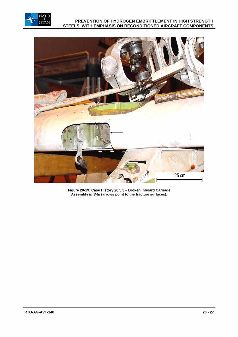
20.5.3 Flap Carriage Assembly The inboard carriage assembly from a transport aircraft flap fractured at the transition radius between the spindle and fork, see Figure 20-20 and Figure 20-21. The operator carried out a failure investigation, which is described in Section 20.5.3.1. The National Aerospace Laboratory (NLR) in Emmeloord, Netherlands, was requested to review the investigation and provide comments. The NLR’s contribution is given in Section 20.5.3.2. The remedial actions and final conclusions are presented in Section 20.5.3.3.
20.5.3.1 Failure Investigation by the Operator
The broken carriage assembly was made from AISI 4330 M low alloy steel heat-treated to a Rockwell hardness of 53 HRC, corresponding to a tensile strength in the range 1860 – 2060 MPa. About 3 years before failure the spindle had undergone repair involving corrosion removal and nickel electroplating.
The failure investigation comprised the following steps:
• Visual examination and description.
• Optical fractography.
• Metallographic cross-sections.
• Review of the repair history.
• Conclusions.
20.5.3.1.1 Visual Examination and Description
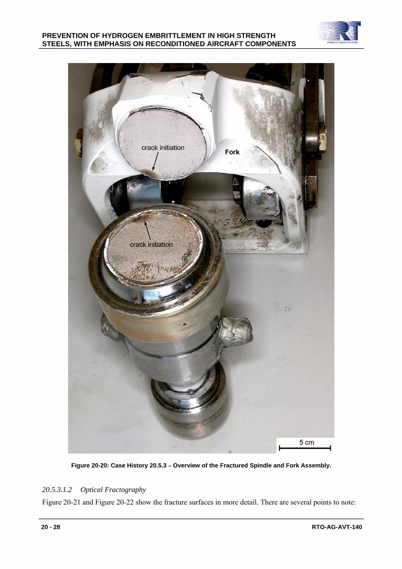
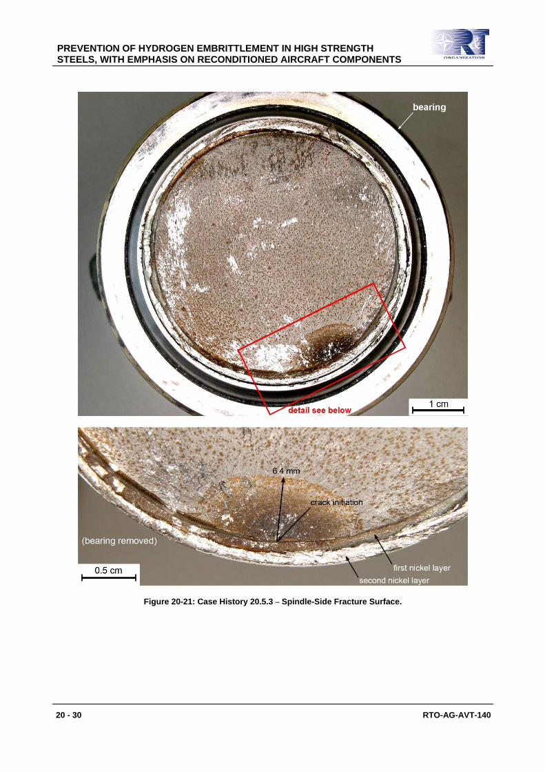
Figure 20-19 shows the broken carriage assembly in situ, and Figure 20-20 gives views of the mating fracture surfaces spindle-side and fork-side. Discoloured semi-elliptical crack initiation regions are visible in both figures. The entire fracture surface of the spindle is also discoloured, but less so.
PREVENTION OF HYDROGEN EMBRITTLEMENT IN HIGH STRENGTH STEELS, WITH EMPHASIS ON RECONDITIONED AIRCRAFT COMPONENTS
RTO-AG-AVT-140 20 - 27
Figure 20-19: Case History 20.5.3 – Broken Inboard Carriage Assembly In Situ (arrows point to the fracture surfaces).
PREVENTION OF HYDROGEN EMBRITTLEMENT IN HIGH STRENGTH STEELS, WITH EMPHASIS ON RECONDITIONED AIRCRAFT COMPONENTS
20 - 28 RTO-AG-AVT-140
Figure 20-20: Case History 20.5.3 – Overview of the Fractured Spindle and Fork Assembly.
20.5.3.1.2 Optical Fractography
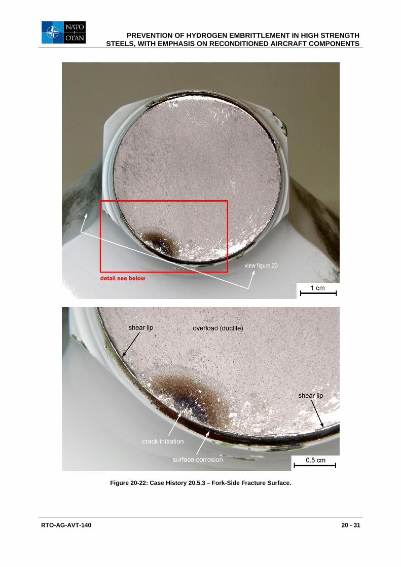
Figure 20-21 and Figure 20-22 show the fracture surfaces in more detail. There are several points to note:
PREVENTION OF HYDROGEN EMBRITTLEMENT IN HIGH STRENGTH STEELS, WITH EMPHASIS ON RECONDITIONED AIRCRAFT COMPONENTS
RTO-AG-AVT-140 20 - 29
1) Both crack initiation regions had discolorations grading from black to light brown. The spindle-side fracture surface was also discoloured by post-failure rust spots.
2) The spindle-side steel surface was covered by two nickel plating layers, see Figure 20-21.
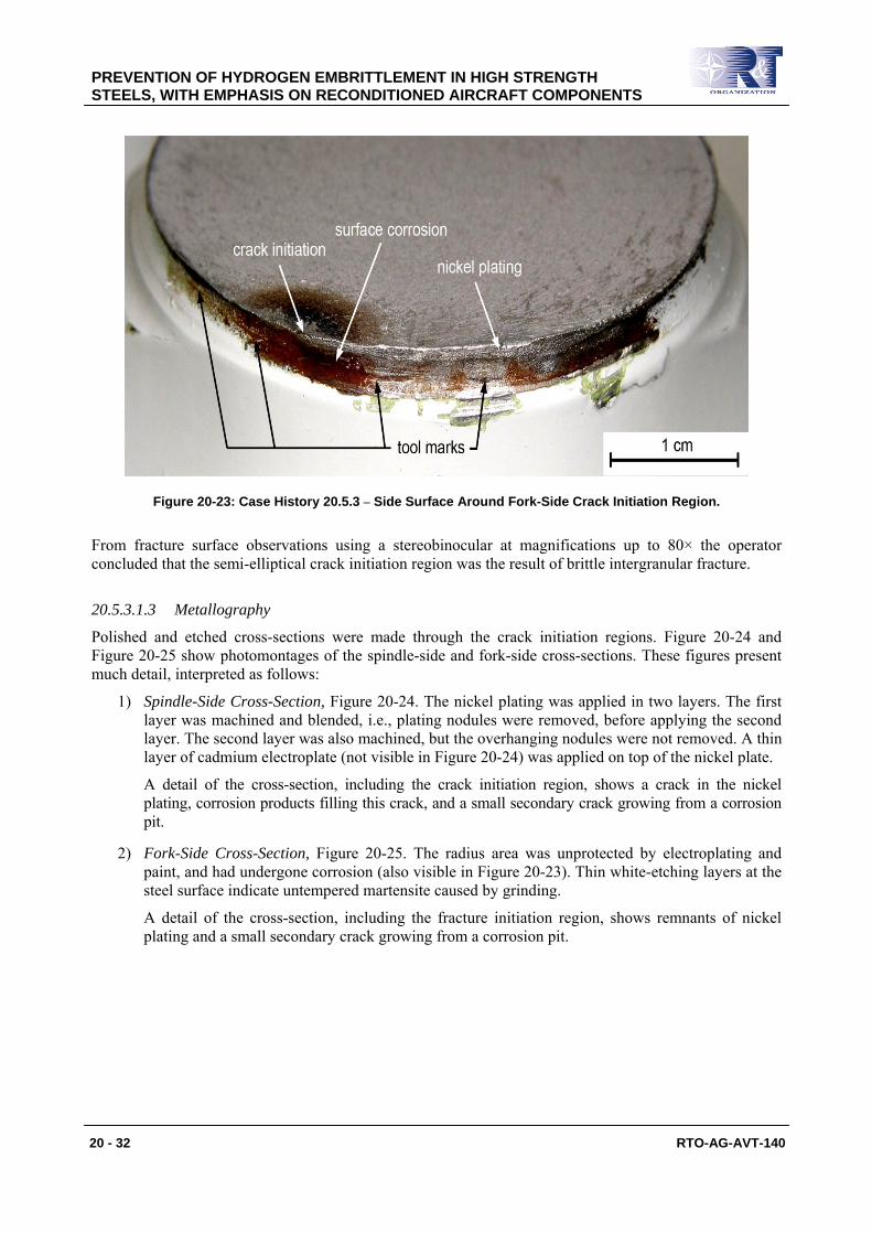
3) Side surface corrosion was present just below the fork-side fracture surface, see Figure 20-22. This corrosion is seen in more detail in Figure 20-23, which also shows a thin remnant of nickel plating and tool marks owing to grinding away excess nickel plate.
PREVENTION OF HYDROGEN EMBRITTLEMENT IN HIGH STRENGTH STEELS, WITH EMPHASIS ON RECONDITIONED AIRCRAFT COMPONENTS
20 - 30 RTO-AG-AVT-140
Figure 20-21: Case History 20.5.3 – Spindle-Side Fracture Surface.
PREVENTION OF HYDROGEN EMBRITTLEMENT IN HIGH STRENGTH STEELS, WITH EMPHASIS ON RECONDITIONED AIRCRAFT COMPONENTS
RTO-AG-AVT-140 20 - 31
Figure 20-22: Case History 20.5.3 – Fork-Side Fracture Surface.
PREVENTION OF HYDROGEN EMBRITTLEMENT IN HIGH STRENGTH STEELS, WITH EMPHASIS ON RECONDITIONED AIRCRAFT COMPONENTS
20 - 32 RTO-AG-AVT-140
Figure 20-23: Case History 20.5.3 – Side Surface Around Fork-Side Crack Initiation Region.
From fracture surface observations using a stereobinocular at magnifications up to 80× the operator concluded that the semi-elliptical crack initiation region was the result of brittle intergranular fracture.
20.5.3.1.3 Metallography
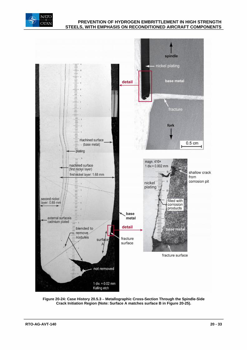
Polished and etched cross-sections were made through the crack initiation regions. Figure 20-24 and Figure 20-25 show photomontages of the spindle-side and fork-side cross-sections. These figures present much detail, interpreted as follows:
1) Spindle-Side Cross-Section, Figure 20-24. The nickel plating was applied in two layers. The first layer was machined and blended, i.e., plating nodules were removed, before applying the second layer. The second layer was also machined, but the overhanging nodules were not removed. A thin layer of cadmium electroplate (not visible in Figure 20-24) was applied on top of the nickel plate.
A detail of the cross-section, including the crack initiation region, shows a crack in the nickel plating, corrosion products filling this crack, and a small secondary crack growing from a corrosion pit.
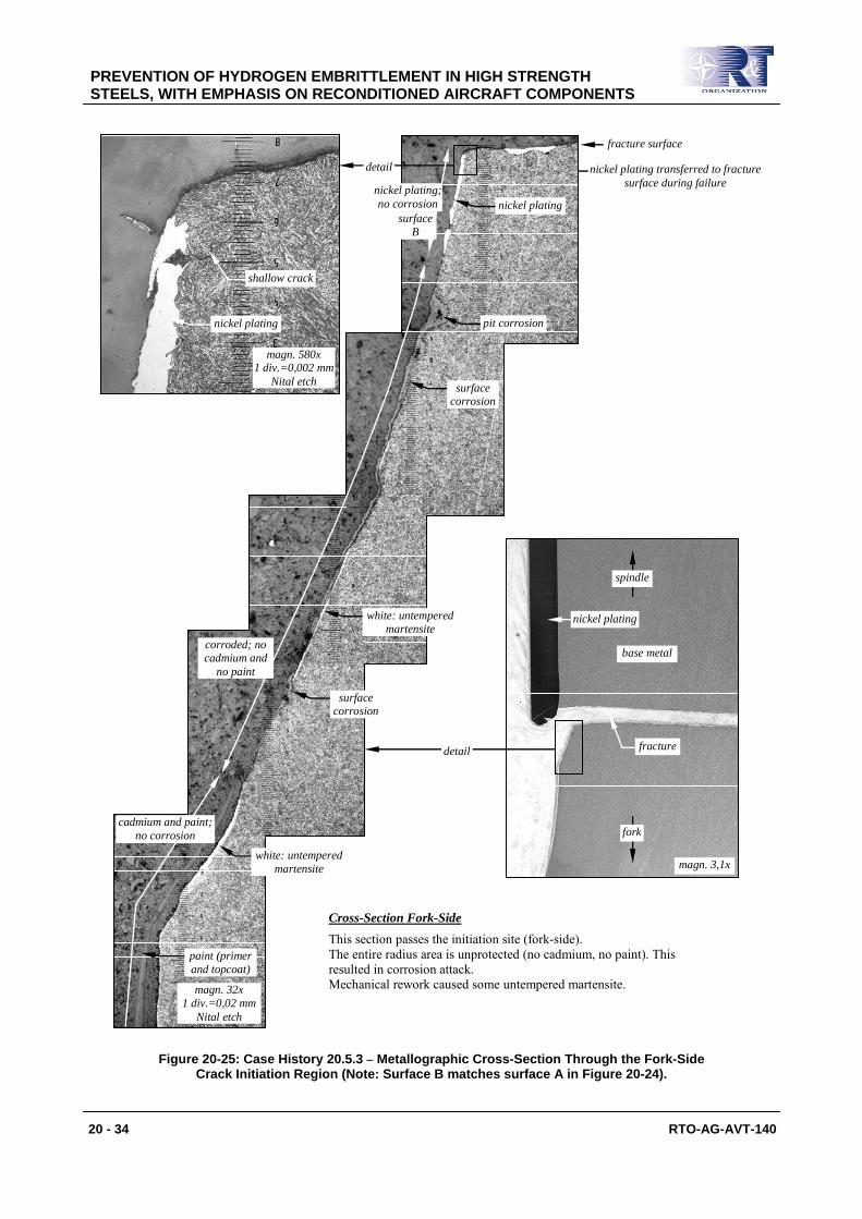
2) Fork-Side Cross-Section, Figure 20-25. The radius area was unprotected by electroplating and paint, and had undergone corrosion (also visible in Figure 20-23). Thin white-etching layers at the steel surface indicate untempered martensite caused by grinding.
A detail of the cross-section, including the fracture initiation region, shows remnants of nickel plating and a small secondary crack growing from a corrosion pit.
PREVENTION OF HYDROGEN EMBRITTLEMENT IN HIGH STRENGTH STEELS, WITH EMPHASIS ON RECONDITIONED AIRCRAFT COMPONENTS
RTO-AG-AVT-140 20 - 33
Figure 20-24: Case History 20.5.3 – Metallographic Cross-Section Through the Spindle-Side Crack Initiation Region (Note: Surface A matches surface B in Figure 20-25).
PREVENTION OF HYDROGEN EMBRITTLEMENT IN HIGH STRENGTH STEELS, WITH EMPHASIS ON RECONDITIONED AIRCRAFT COMPONENTS
20 - 34 RTO-AG-AVT-140
nickel plating transferred to fracture
surface during failure
Cross-Section Fork-Side
This section passes the initiation site (fork-side). The entire radius area is unprotected (no cadmium, no paint). This resulted in corrosion attack. Mechanical rework caused some untempered martensite.
magn. 3,1x
magn. 32x 1 div.=0,02 mm
Nital etch
magn. 580x 1 div.=0,002 mm
Nital etch
nickel plating
fracture surface
detail
surface corrosion
shallow crack
pit corrosion
white: untempered martensite
white: untempered martensite
nickel plating
base metal
fracture
fork
spindle
detail
paint (primer and topcoat)
cadmium and paint; no corrosion
corroded; no cadmium and
no paint
nickel plating; no corrosion
nickel plating
surface B
surface corrosion
Figure 20-25: Case History 20.5.3 – Metallographic Cross-Section Through the Fork-Side Crack Initiation Region (Note: Surface B matches surface A in Figure 20-24).
PREVENTION OF HYDROGEN EMBRITTLEMENT IN HIGH STRENGTH STEELS, WITH EMPHASIS ON RECONDITIONED AIRCRAFT COMPONENTS
RTO-AG-AVT-140 20 - 35
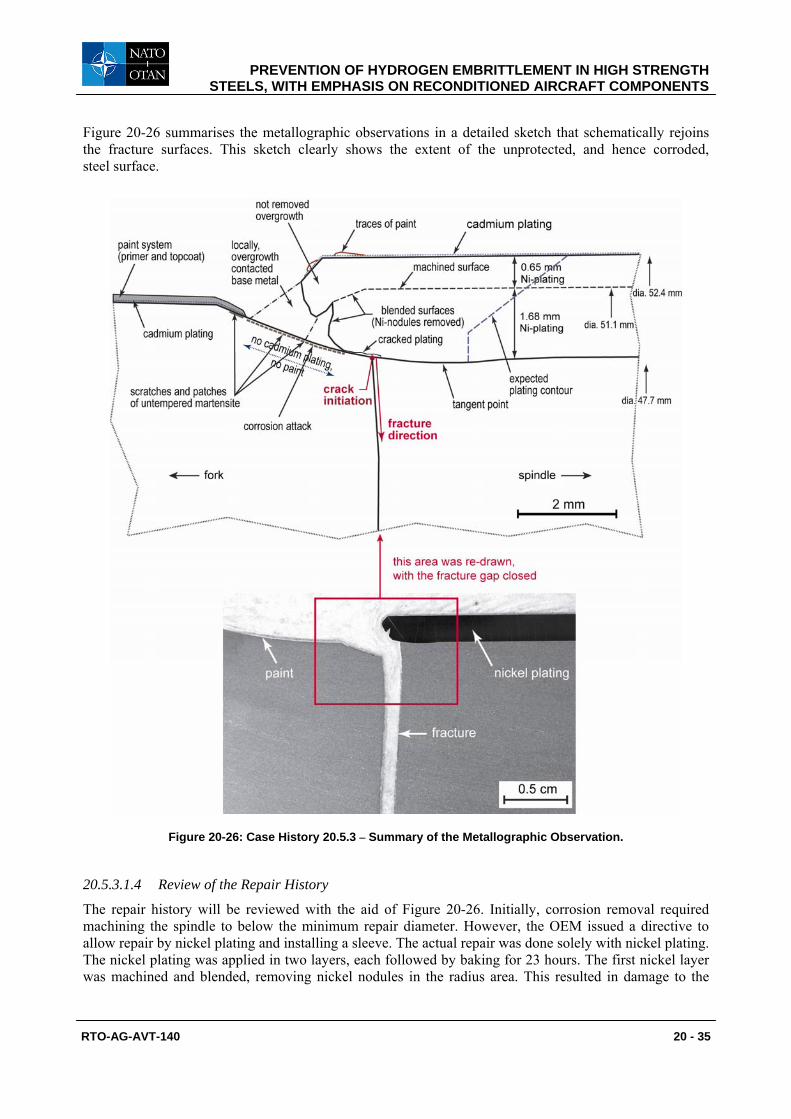
Figure 20-26 summarises the metallographic observations in a detailed sketch that schematically rejoins the fracture surfaces. This sketch clearly shows the extent of the unprotected, and hence corroded, steel surface.
Figure 20-26: Case History 20.5.3 – Summary of the Metallographic Observation.
20.5.3.1.4 Review of the Repair History
The repair history will be reviewed with the aid of Figure 20-26. Initially, corrosion removal required machining the spindle to below the minimum repair diameter. However, the OEM issued a directive to allow repair by nickel plating and installing a sleeve. The actual repair was done solely with nickel plating. The nickel plating was applied in two layers, each followed by baking for 23 hours. The first nickel layer was machined and blended, removing nickel nodules in the radius area. This resulted in damage to the
PREVENTION OF HYDROGEN EMBRITTLEMENT IN HIGH STRENGTH STEELS, WITH EMPHASIS ON RECONDITIONED AIRCRAFT COMPONENTS
20 - 36 RTO-AG-AVT-140
steel surface (tool marks, see Figure 20-22, and untempered martensite, see Figure 20-25). The second nickel layer was also machined, but the overhanging nodules in the radius area were not removed.
Finally, the entire assembly was cadmium electroplated and painted.
20.5.3.1.5 Conclusions The operator attributed failure of the carriage assembly to poor repair procedures:
1) The nickel plating thickness was excessive: up to 2.33 mm instead of the maximum allowable thickness of 1.5 mm. Because of this, baking for 23 hours might have been insufficient to remove all the hydrogen picked up during plating.
2) Near the steel crack initiation region the nickel plating was cracked and filled with corrosion products. This crack in the nickel plating could have resulted in a corrosion pit at the steel crack initiation region.
3) In the light of 1) and 2), cracking of the steel may have been due to a combination of stress corrosion and hydrogen embrittlement.
4) Corrosion in the spindle radius area occurred because overhanging nickel nodules from the second nickel plating layer prevented the final cadmium plating and painting from covering the radius area.
20.5.3.2 Review of the Operator’s Investigation The operator’s report on the investigation was sent to the NLR for comments. The NLR agreed that failure of the carriage assembly was due to poor repair procedures. However, there were some comments and observations about the interpretation of cracking:
1) Stereobinocular fractography at magnifications up to 80 × would normally have been sufficient to determine whether brittle intergranular fracture had occurred. However, the fracture surfaces were corroded, which would have made interpretation difficult.
2) Figure 20-21 and Figure 20-22 show discolorations grading from black to light brown on the fracture surfaces of the crack initiation region. These discolorations are the result of progressive oxidation during crack growth, and their gradual transition from black to light brown is characteristic for both stress corrosion and corrosion fatigue in steels. On the other hand, the service loading on the carriage assembly would have been mainly cyclic (flaps in, flaps out) rather than sustained. (N.B.: See Section 20.3 2) also.)
3) Other features pointing to corrosion fatigue rather than IHE or a combination of IHE and stress corrosion are: a) The location of the failure, which was near the root of a notch created by the end of the nickel
plating and a crack in the nickel plating3; b) The well-defined semi-elliptical shape of the crack initiation regions, although similar crack
shapes are possible for IHE and stress corrosion, see case history 20.5.1; c) The close proximity of the secondary cracks growing from adjacent corrosion pits, but not
from corrosion damage further from the failure site; and d) No cracks in the regions of untempered martensite, see the details in Figure 20-24 – Figure
20-26.
4) Nickel electroplating was most probably carried out using a sulfamate bath, a type of bath which results in only moderate hydrogen pick-up by high strength steels. More importantly, there was an unplated “window”, see Figure 20-25 and Figure 20-26, through which hydrogen could have readily diffused, both during and after the baking.
3 The nickel plating would have had sufficient stiffness and strength to be load-bearing, and hence provide a notch at its end.
PREVENTION OF HYDROGEN EMBRITTLEMENT IN HIGH STRENGTH STEELS, WITH EMPHASIS ON RECONDITIONED AIRCRAFT COMPONENTS
RTO-AG-AVT-140 20 - 37
5) Figure 20-25 shows an anomaly, namely that the operator indicated nickel plate to have been transferred to the fracture surface during failure. This is most unlikely. However, the operator’s report mentioned that the two fracture halves were reassembled to visualize the nickel plating transition in the radius. It is possible that this reassembly – which should not have been done! – caused smearing of some loosened or protruding nickel plate onto the fracture surface.
From the comments and observations in 1) – 4) the NLR concluded that the carriage assembly failure was most probably the result of corrosion fatigue rather than IHE.
20.5.3.3 Remedial Actions and Final Conclusions
The OEM responded to the operator’s investigation by requiring all carriage assemblies with similar repair histories to be replaced. Specifically, the OEM considered that baking for 23 hours was insufficient to guarantee satisfactory long-term service. The failed and suspect carriage assemblies were replaced by new ones. However, in the light of the NLR’s comments the OEM subsequently conceded that baking for 23 hours was adequate.
The operator concluded that the failed carriage assembly was an “isolated case” owing to very poor repair procedures. The cause of cracking remains uncertain, though it was most probably corrosion fatigue and not hydrogen embrittlement.
20.5.4 Wing Attachment Fitting Bolts
20.5.4.1 Introduction
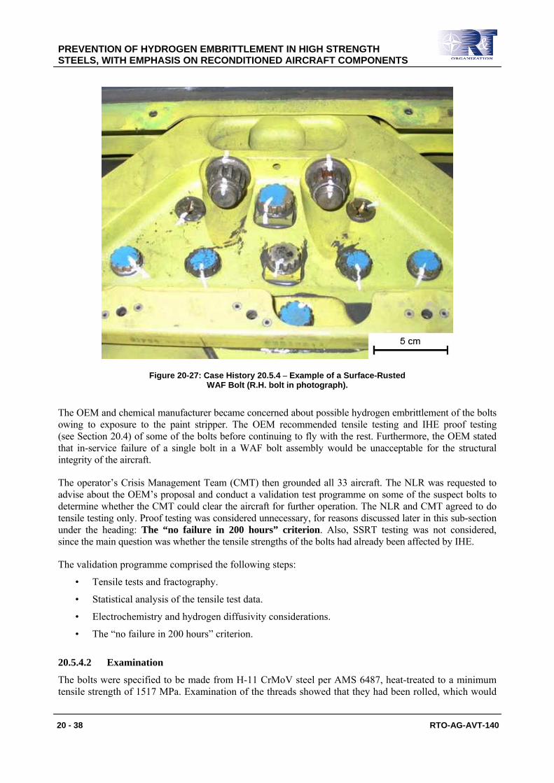
During a modification programme the Wing Attachment Fitting (WAF) steel bolt assemblies from 33 tactical aircraft were cleaned in a non-approved chemical solution, a paint stripper. This removed much of the cadmium electroplating on the bolts, nuts and washers, leading to in-service superficial rusting of some bolt ends and nuts, e.g., Figure 20-27.
PREVENTION OF HYDROGEN EMBRITTLEMENT IN HIGH STRENGTH STEELS, WITH EMPHASIS ON RECONDITIONED AIRCRAFT COMPONENTS
20 - 38 RTO-AG-AVT-140
Figure 20-27: Case History 20.5.4 – Example of a Surface-Rusted WAF Bolt (R.H. bolt in photograph).
The OEM and chemical manufacturer became concerned about possible hydrogen embrittlement of the bolts owing to exposure to the paint stripper. The OEM recommended tensile testing and IHE proof testing (see Section 20.4) of some of the bolts before continuing to fly with the rest. Furthermore, the OEM stated that in-service failure of a single bolt in a WAF bolt assembly would be unacceptable for the structural integrity of the aircraft.
The operator’s Crisis Management Team (CMT) then grounded all 33 aircraft. The NLR was requested to advise about the OEM’s proposal and conduct a validation test programme on some of the suspect bolts to determine whether the CMT could clear the aircraft for further operation. The NLR and CMT agreed to do tensile testing only. Proof testing was considered unnecessary, for reasons discussed later in this sub-section under the heading: The “no failure in 200 hours” criterion. Also, SSRT testing was not considered, since the main question was whether the tensile strengths of the bolts had already been affected by IHE.
The validation programme comprised the following steps:
• Tensile tests and fractography.
• Statistical analysis of the tensile test data.
• Electrochemistry and hydrogen diffusivity considerations.
• The “no failure in 200 hours” criterion.
20.5.4.2 Examination
The bolts were specified to be made from H-11 CrMoV steel per AMS 6487, heat-treated to a minimum tensile strength of 1517 MPa. Examination of the threads showed that they had been rolled, which would
PREVENTION OF HYDROGEN EMBRITTLEMENT IN HIGH STRENGTH STEELS, WITH EMPHASIS ON RECONDITIONED AIRCRAFT COMPONENTS
RTO-AG-AVT-140 20 - 39
have been beneficial to their resistance to cracking, particularly if thread rolling was done after heat treatment, thereby introducing compressive residual stresses at the thread roots. (It was not determined whether heat treatment preceded the thread rolling.)
20.5.4.2.1 Tensile Tests
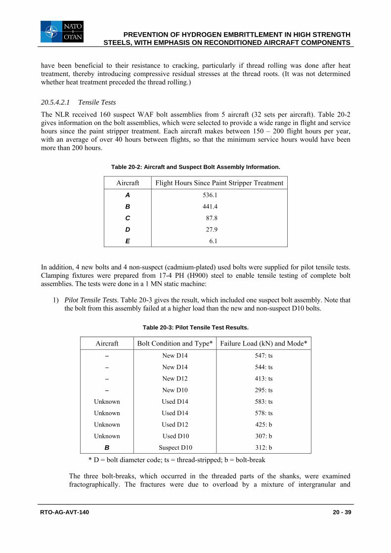
The NLR received 160 suspect WAF bolt assemblies from 5 aircraft (32 sets per aircraft). Table 20-2 gives information on the bolt assemblies, which were selected to provide a wide range in flight and service hours since the paint stripper treatment. Each aircraft makes between 150 – 200 flight hours per year, with an average of over 40 hours between flights, so that the minimum service hours would have been more than 200 hours.
Table 20-2: Aircraft and Suspect Bolt Assembly Information.
Aircraft Flight Hours Since Paint Stripper Treatment
A
B
C
D
E
536.1
441.4
87.8
27.9
6.1
In addition, 4 new bolts and 4 non-suspect (cadmium-plated) used bolts were supplied for pilot tensile tests. Clamping fixtures were prepared from 17-4 PH (H900) steel to enable tensile testing of complete bolt assemblies. The tests were done in a 1 MN static machine:
1) Pilot Tensile Tests. Table 20-3 gives the result, which included one suspect bolt assembly. Note that the bolt from this assembly failed at a higher load than the new and non-suspect D10 bolts.
Table 20-3: Pilot Tensile Test Results.
Aircraft Bolt Condition and Type* Failure Load (kN) and Mode*
–
–
–
–
Unknown
Unknown
Unknown
Unknown
B
New D14
New D14
New D12
New D10
Used D14
Used D14
Used D12
Used D10
Suspect D10
547: ts
544: ts
413: ts
295: ts
583: ts
578: ts
425: b
307: b
312: b
* D = bolt diameter code; ts = thread-stripped; b = bolt-break
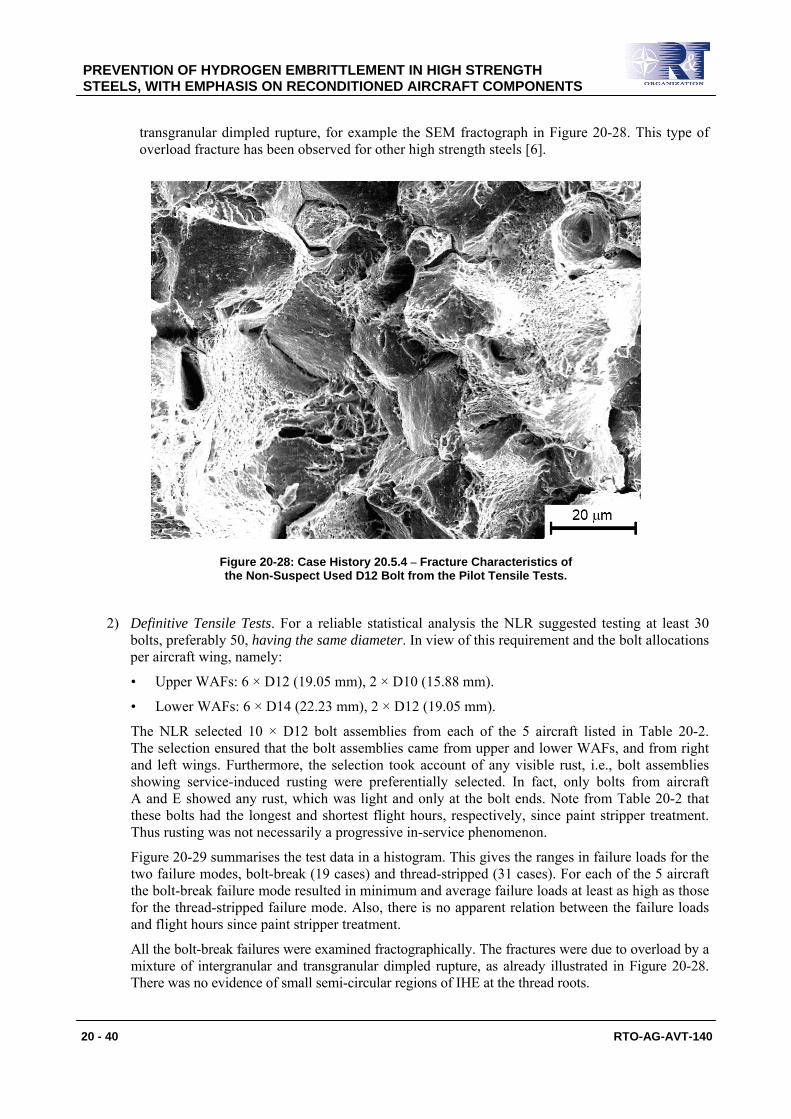
The three bolt-breaks, which occurred in the threaded parts of the shanks, were examined fractographically. The fractures were due to overload by a mixture of intergranular and
PREVENTION OF HYDROGEN EMBRITTLEMENT IN HIGH STRENGTH STEELS, WITH EMPHASIS ON RECONDITIONED AIRCRAFT COMPONENTS
20 - 40 RTO-AG-AVT-140
transgranular dimpled rupture, for example the SEM fractograph in Figure 20-28. This type of overload fracture has been observed for other high strength steels [6].
Figure 20-28: Case History 20.5.4 – Fracture Characteristics of the Non-Suspect Used D12 Bolt from the Pilot Tensile Tests.
2) Definitive Tensile Tests. For a reliable statistical analysis the NLR suggested testing at least 30 bolts, preferably 50, having the same diameter. In view of this requirement and the bolt allocations per aircraft wing, namely:
• Upper WAFs: 6 × D12 (19.05 mm), 2 × D10 (15.88 mm).
• Lower WAFs: 6 × D14 (22.23 mm), 2 × D12 (19.05 mm).
The NLR selected 10 × D12 bolt assemblies from each of the 5 aircraft listed in Table 20-2. The selection ensured that the bolt assemblies came from upper and lower WAFs, and from right and left wings. Furthermore, the selection took account of any visible rust, i.e., bolt assemblies showing service-induced rusting were preferentially selected. In fact, only bolts from aircraft A and E showed any rust, which was light and only at the bolt ends. Note from Table 20-2 that these bolts had the longest and shortest flight hours, respectively, since paint stripper treatment. Thus rusting was not necessarily a progressive in-service phenomenon.
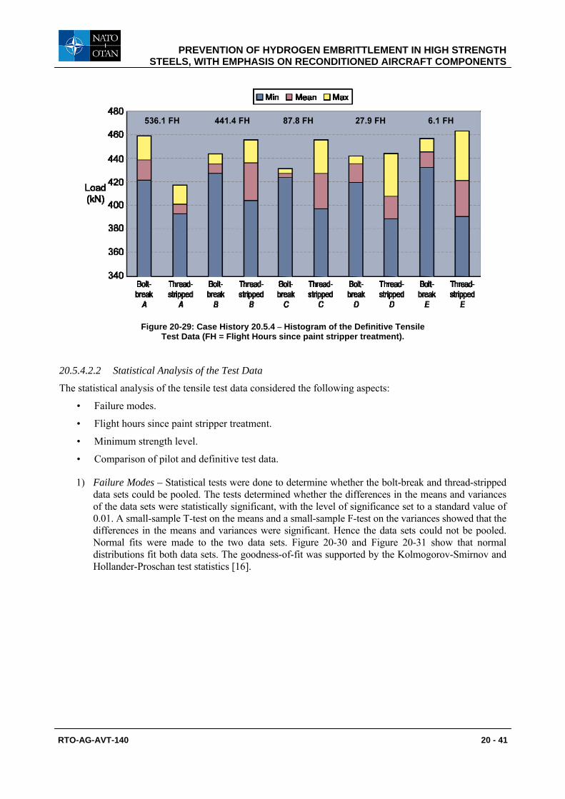
Figure 20-29 summarises the test data in a histogram. This gives the ranges in failure loads for the two failure modes, bolt-break (19 cases) and thread-stripped (31 cases). For each of the 5 aircraft the bolt-break failure mode resulted in minimum and average failure loads at least as high as those for the thread-stripped failure mode. Also, there is no apparent relation between the failure loads and flight hours since paint stripper treatment.
All the bolt-break failures were examined fractographically. The fractures were due to overload by a mixture of intergranular and transgranular dimpled rupture, as already illustrated in Figure 20-28. There was no evidence of small semi-circular regions of IHE at the thread roots.
PREVENTION OF HYDROGEN EMBRITTLEMENT IN HIGH STRENGTH STEELS, WITH EMPHASIS ON RECONDITIONED AIRCRAFT COMPONENTS
RTO-AG-AVT-140 20 - 41
Figure 20-29: Case History 20.5.4 – Histogram of the Definitive Tensile Test Data (FH = Flight Hours since paint stripper treatment).
20.5.4.2.2 Statistical Analysis of the Test Data
The statistical analysis of the tensile test data considered the following aspects:
• Failure modes.
• Flight hours since paint stripper treatment.
• Minimum strength level.
• Comparison of pilot and definitive test data.
1) Failure Modes – Statistical tests were done to determine whether the bolt-break and thread-stripped data sets could be pooled. The tests determined whether the differences in the means and variances of the data sets were statistically significant, with the level of significance set to a standard value of 0.01. A small-sample T-test on the means and a small-sample F-test on the variances showed that the differences in the means and variances were significant. Hence the data sets could not be pooled. Normal fits were made to the two data sets. Figure 20-30 and Figure 20-31 show that normal distributions fit both data sets. The goodness-of-fit was supported by the Kolmogorov-Smirnov and Hollander-Proschan test statistics [16].

PREVENTION OF HYDROGEN EMBRITTLEMENT IN HIGH STRENGTH STEELS, WITH EMPHASIS ON RECONDITIONED AIRCRAFT COMPONENTS
20 - 42 RTO-AG-AVT-140
Figure 20-30: Case History 20.5.4 – Normal Fit for the Bolt-Break Failure Load Data from the Definitive Tensile Tests.
Figure 20-31: Case History 20.5.4 – Normal Fit for the Thread-Stripped Failure Load Data from the Definitive Tensile Tests.
PREVENTION OF HYDROGEN EMBRITTLEMENT IN HIGH STRENGTH STEELS, WITH EMPHASIS ON RECONDITIONED AIRCRAFT COMPONENTS
RTO-AG-AVT-140 20 - 43
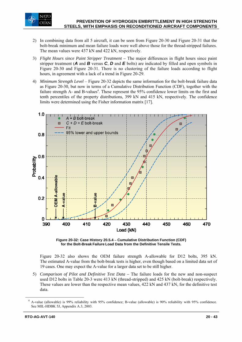
2) In combining data from all 5 aircraft, it can be seen from Figure 20-30 and Figure 20-31 that the bolt-break minimum and mean failure loads were well above those for the thread-stripped failures. The mean values were 437 kN and 422 kN, respectively.
3) Flight Hours since Paint Stripper Treatment – The major differences in flight hours since paint stripper treatment (A and B versus C, D and E bolts) are indicated by filled and open symbols in Figure 20-30 and Figure 20-31. There is no clustering of the failure loads according to flight hours, in agreement with a lack of a trend in Figure 20-29.
4) Minimum Strength Level – Figure 20-32 depicts the same information for the bolt-break failure data as Figure 20-30, but now in terms of a Cumulative Distribution Function (CDF), together with the failure strength A- and B-values4. These represent the 95% confidence lower limits on the first and tenth percentiles of the property distributions, 399 kN and 415 kN, respectively. The confidence limits were determined using the Fisher information matrix [17].
Figure 20-32: Case History 20.5.4 – Cumulative Distribution Function (CDF) for the Bolt-Break Failure Load Data from the Definitive Tensile Tests.
Figure 20-32 also shows the OEM failure strength A-allowable for D12 bolts, 395 kN. The estimated A-value from the bolt-break tests is higher, even though based on a limited data set of 19 cases. One may expect the A-value for a larger data set to be still higher.
5) Comparison of Pilot and Definitive Test Data – The failure loads for the new and non-suspect used D12 bolts in Table 20-3 were 413 kN (thread-stripped) and 425 kN (bolt-break) respectively. These values are lower than the respective mean values, 422 kN and 437 kN, for the definitive test data.
4 A-value (allowable) is 99% reliability with 95% confidence; B-value (allowable) is 90% reliability with 95% confidence.
See MIL-HDBK 5J, Appendix A.3, 2003.
PREVENTION OF HYDROGEN EMBRITTLEMENT IN HIGH STRENGTH STEELS, WITH EMPHASIS ON RECONDITIONED AIRCRAFT COMPONENTS
20 - 44 RTO-AG-AVT-140
The results of the statistical analysis strongly suggested that the suspect D12 bolt assemblies had not undergone tensile failure load degradation owing to IHE caused by the paint stripper treatment. Furthermore, the fact that the bolt-break minimum and average failure loads were well above those for the thread-stripped failures suggests that the bolt shank material below the thread roots was undamaged. This is because (possible) hydrogen embrittlement of service-loaded bolts would be expected to damage the material subjected to tensile stress concentrations below the thread roots, but not the threads themselves.
20.5.4.2.3 Electrochemistry and Hydrogen Diffusivity Considerations
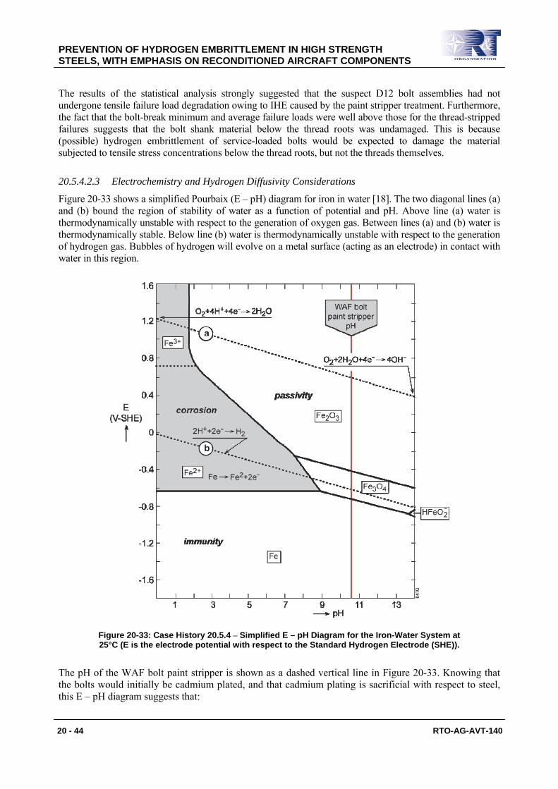
Figure 20-33 shows a simplified Pourbaix (E – pH) diagram for iron in water [18]. The two diagonal lines (a) and (b) bound the region of stability of water as a function of potential and pH. Above line (a) water is thermodynamically unstable with respect to the generation of oxygen gas. Between lines (a) and (b) water is thermodynamically stable. Below line (b) water is thermodynamically unstable with respect to the generation of hydrogen gas. Bubbles of hydrogen will evolve on a metal surface (acting as an electrode) in contact with water in this region.
Figure 20-33: Case History 20.5.4 – Simplified E – pH Diagram for the Iron-Water System at 25°C (E is the electrode potential with respect to the Standard Hydrogen Electrode (SHE)).
The pH of the WAF bolt paint stripper is shown as a dashed vertical line in Figure 20-33. Knowing that the bolts would initially be cadmium plated, and that cadmium plating is sacrificial with respect to steel, this E – pH diagram suggests that:
PREVENTION OF HYDROGEN EMBRITTLEMENT IN HIGH STRENGTH STEELS, WITH EMPHASIS ON RECONDITIONED AIRCRAFT COMPONENTS
RTO-AG-AVT-140 20 - 45
1) Depending on the cadmium/steel galvanic coupling potential, i.e., if it would be below about -0.6 V-SHE, hydrogen gas could be liberated at the cadmium/steel interface during the anodic attack and removal of the cadmium layer by the paint stripper. Some hydrogen could also be absorbed by the bolts, as discussed below.
2) The bolts would not corrode in the paint stripper, since its pH line is well outside the corrosion region. Note that the suggestion about no corrosion of the bolts is consistent with measurements of the open-circuit potential of another low alloy steel (4340) in paint strippers having pH values ranging from 8 – 11.5 [19]. These measurements showed that the bare steel was in the water-stable (passivity) region of the E – pH diagram. In other words, even if all the cadmium plating on the WAF bolts were to be removed by anodic attack, the bolts would remain uncorroded. (In fact, as mentioned earlier, inspection of all the suspect bolts before tensile testing showed no evidence of corrosion except service-induced light rusting on some of the bolt ends from the aircraft A and E.)
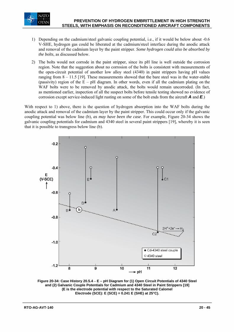
With respect to 1) above, there is the question of hydrogen absorption into the WAF bolts during the anodic attack and removal of the cadmium layer by the paint stripper. This could occur only if the galvanic coupling potential was below line (b), as may have been the case. For example, Figure 20-34 shows the galvanic coupling potentials for cadmium and 4340 steel in several paint strippers [19], whereby it is seen that it is possible to transgress below line (b).
Figure 20-34: Case History 20.5.4 – E – pH Diagram for (1) Open Circuit Potentials of 4340 Steel and (2) Galvanic Couple Potentials for Cadmium and 4340 Steel in Paint Strippers [19]
(E is the electrode potential with respect to the Saturated Calomel Electrode (SCE): E (SCE) = 0.241 E (SHE) at 25°C).
PREVENTION OF HYDROGEN EMBRITTLEMENT IN HIGH STRENGTH STEELS, WITH EMPHASIS ON RECONDITIONED AIRCRAFT COMPONENTS
20 - 46 RTO-AG-AVT-140
The only driving force for hydrogen absorption would be electrochemical, since the WAF bolts were not under applied tensile stresses (service loads) during paint stripper treatment and the subsequent time before reinstallation in the aircraft structure. This means that much or all of the hydrogen that might have been absorbed could have diffused out through the bare steel surface once the bolts were removed from the paint stripper. An estimate of the time taken for any absorbed hydrogen to diffuse out of the bolts can be made as follows.
The checks mentioned in the introduction to this case history showed that the maximum time in paint stripper would have been no more than 3 days. The diffusion distance into the steel is given by tDX .= , where D is the diffusion coefficient for hydrogen build-up in the steel and t is the time. The diffusion coefficients for build-up and decay of hydrogen in high strength steels are 2.2 × 10⁻⁷ cm2/s and 0.85 × 10⁻⁷ cm2/s, respectively [3]. Let X be the same distance during hydrogen build-up and decay. Then the time required for all the introduced hydrogen to diffuse out of the steel is given by:
t2 = t1 × D1/D2
Substituting 72 hours for t1 and 2.2 × 10⁻⁷ cm2/s and 0.85 × 10⁻⁷ cm2/s for D1 and D2, we obtain t2 = 186 hours, which is slightly less than 8 days. This is less than the time between paint stripping and reinstallation in the aircraft structure, which was 3 – 4 weeks.
Summarising, it appears unlikely that exposure of the WAF bolts paint stripper would lead to retention of any absorbed hydrogen by the time they were reinstalled in the aircraft. Nor were the bolts damaged by corrosion in the paint stripper, see point (2) above.
20.5.4.2.4 The “No Failure in 200 Hours” Criterion In the introduction to this case history it was mentioned that the OEM recommended IHE proof testing as well as tensile testing. The OEM first suggested proof testing per ASTM Standard F519-06 [7] and later per NASM1312-5 [9], whereby suspect and new WAF bolts would be subjected to sustained tensile loads at 75% of the notched fracture stress for 200 hours. Survival for 200 hours would validate the suspect bolts. This is the “no failure in 200 hours criterion” obtained from Troiano’s classic data [10], see Figure 20-4, and discussed in Section 20.4.3. For the WAF bolt validation programme the most important point from Troiano’s data is that most embrittled specimens failed well within 200 hours, in fact within 10 hours. This result is relevant to the service experience of the WAF bolts after paint stripper treatment. All these bolts had survived more than 200 service hours in the fully-torqued condition, making it very unlikely that they had been embrittled. This viewpoint, without elaboration, was used in arriving at the conclusions and remedial actions below. Subsequently it was possible to be more specific in justifying this viewpoint, see the Postscript after the remedial actions.
20.5.4.3 Conclusions 1) The tensile test results and analysis, fractography, and a discussion of electrochemical and hydrogen
diffusivity considerations and the “no failure in 200 hours” criterion, led to the NLR’s conclusion that the WAF bolt tensile failure strengths were validated as unaffected by the paint stripper.
2) The data in Figure 20-34 show that some paint strippers can cause hydrogen pick-up in cadmium plated high strength steels. Hence relaxation of the proof test duration from 200 hours to 150 hours in so-called passive service environments, as mentioned in Section 20.4.3, is not necessarily advisable.
20.5.4.4 Remedial Actions The CMT cleared the aircraft for further operation, whereby all the remaining WAF bolt assemblies were cleaned with an approved cleaner and protected with primer. These assemblies were subsequently replaced at the latest during the next scheduled inspection.
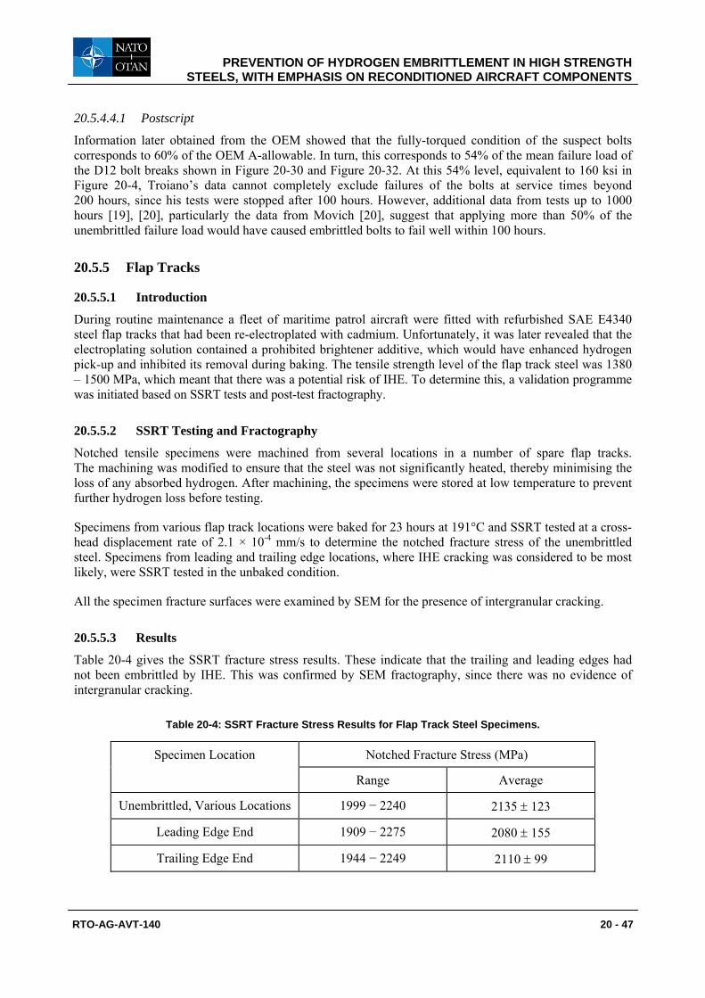
PREVENTION OF HYDROGEN EMBRITTLEMENT IN HIGH STRENGTH STEELS, WITH EMPHASIS ON RECONDITIONED AIRCRAFT COMPONENTS
RTO-AG-AVT-140 20 - 47
20.5.4.4.1 Postscript
Information later obtained from the OEM showed that the fully-torqued condition of the suspect bolts corresponds to 60% of the OEM A-allowable. In turn, this corresponds to 54% of the mean failure load of the D12 bolt breaks shown in Figure 20-30 and Figure 20-32. At this 54% level, equivalent to 160 ksi in Figure 20-4, Troiano’s data cannot completely exclude failures of the bolts at service times beyond 200 hours, since his tests were stopped after 100 hours. However, additional data from tests up to 1000 hours [19], [20], particularly the data from Movich [20], suggest that applying more than 50% of the unembrittled failure load would have caused embrittled bolts to fail well within 100 hours.
20.5.5 Flap Tracks
20.5.5.1 Introduction
During routine maintenance a fleet of maritime patrol aircraft were fitted with refurbished SAE E4340 steel flap tracks that had been re-electroplated with cadmium. Unfortunately, it was later revealed that the electroplating solution contained a prohibited brightener additive, which would have enhanced hydrogen pick-up and inhibited its removal during baking. The tensile strength level of the flap track steel was 1380 – 1500 MPa, which meant that there was a potential risk of IHE. To determine this, a validation programme was initiated based on SSRT tests and post-test fractography.
20.5.5.2 SSRT Testing and Fractography
Notched tensile specimens were machined from several locations in a number of spare flap tracks. The machining was modified to ensure that the steel was not significantly heated, thereby minimising the loss of any absorbed hydrogen. After machining, the specimens were stored at low temperature to prevent further hydrogen loss before testing.
Specimens from various flap track locations were baked for 23 hours at 191°C and SSRT tested at a cross-head displacement rate of 2.1 × 10⁻⁴ mm/s to determine the notched fracture stress of the unembrittled steel. Specimens from leading and trailing edge locations, where IHE cracking was considered to be most likely, were SSRT tested in the unbaked condition.
All the specimen fracture surfaces were examined by SEM for the presence of intergranular cracking.
20.5.5.3 Results
Table 20-4 gives the SSRT fracture stress results. These indicate that the trailing and leading edges had not been embrittled by IHE. This was confirmed by SEM fractography, since there was no evidence of intergranular cracking.
Table 20-4: SSRT Fracture Stress Results for Flap Track Steel Specimens.
Specimen Location Notched Fracture Stress (MPa)
Range Average
Unembrittled, Various Locations 1999 − 2240 2135 ± 123
Leading Edge End 1909 − 2275 2080 ± 155
Trailing Edge End 1944 − 2249 2110 ± 99
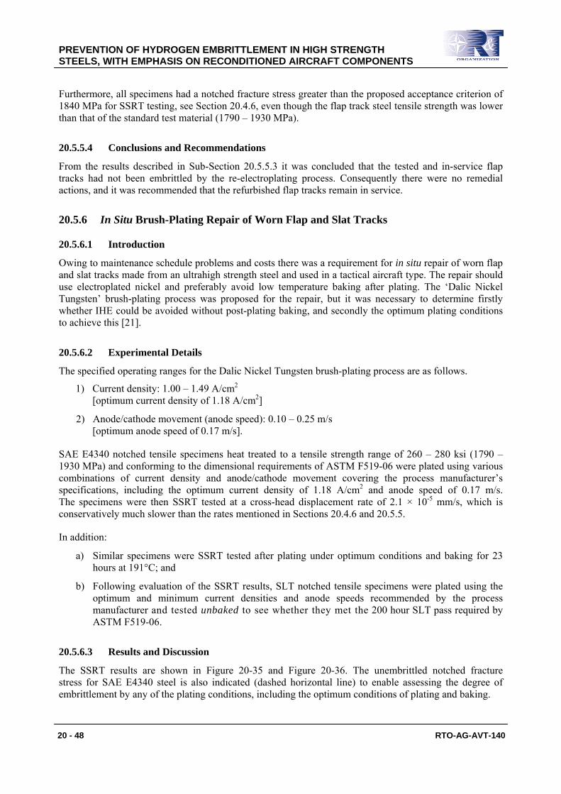
PREVENTION OF HYDROGEN EMBRITTLEMENT IN HIGH STRENGTH STEELS, WITH EMPHASIS ON RECONDITIONED AIRCRAFT COMPONENTS
20 - 48 RTO-AG-AVT-140
Furthermore, all specimens had a notched fracture stress greater than the proposed acceptance criterion of 1840 MPa for SSRT testing, see Section 20.4.6, even though the flap track steel tensile strength was lower than that of the standard test material (1790 – 1930 MPa).
20.5.5.4 Conclusions and Recommendations
From the results described in Sub-Section 20.5.5.3 it was concluded that the tested and in-service flap tracks had not been embrittled by the re-electroplating process. Consequently there were no remedial actions, and it was recommended that the refurbished flap tracks remain in service.
20.5.6 In Situ Brush-Plating Repair of Worn Flap and Slat Tracks
20.5.6.1 Introduction
Owing to maintenance schedule problems and costs there was a requirement for in situ repair of worn flap and slat tracks made from an ultrahigh strength steel and used in a tactical aircraft type. The repair should use electroplated nickel and preferably avoid low temperature baking after plating. The ‘Dalic Nickel Tungsten’ brush-plating process was proposed for the repair, but it was necessary to determine firstly whether IHE could be avoided without post-plating baking, and secondly the optimum plating conditions to achieve this [21].
20.5.6.2 Experimental Details
The specified operating ranges for the Dalic Nickel Tungsten brush-plating process are as follows.
1) Current density: 1.00 – 1.49 A/cm2 [optimum current density of 1.18 A/cm2]
2) Anode/cathode movement (anode speed): 0.10 – 0.25 m/s [optimum anode speed of 0.17 m/s].
SAE E4340 notched tensile specimens heat treated to a tensile strength range of 260 – 280 ksi (1790 – 1930 MPa) and conforming to the dimensional requirements of ASTM F519-06 were plated using various combinations of current density and anode/cathode movement covering the process manufacturer’s specifications, including the optimum current density of 1.18 A/cm2 and anode speed of 0.17 m/s. The specimens were then SSRT tested at a cross-head displacement rate of 2.1 × 10⁻⁵ mm/s, which is conservatively much slower than the rates mentioned in Sections 20.4.6 and 20.5.5.
In addition:
a) Similar specimens were SSRT tested after plating under optimum conditions and baking for 23 hours at 191°C; and
b) Following evaluation of the SSRT results, SLT notched tensile specimens were plated using the optimum and minimum current densities and anode speeds recommended by the process manufacturer and tested unbaked to see whether they met the 200 hour SLT pass required by ASTM F519-06.
20.5.6.3 Results and Discussion
The SSRT results are shown in Figure 20-35 and Figure 20-36. The unembrittled notched fracture stress for SAE E4340 steel is also indicated (dashed horizontal line) to enable assessing the degree of embrittlement by any of the plating conditions, including the optimum conditions of plating and baking.
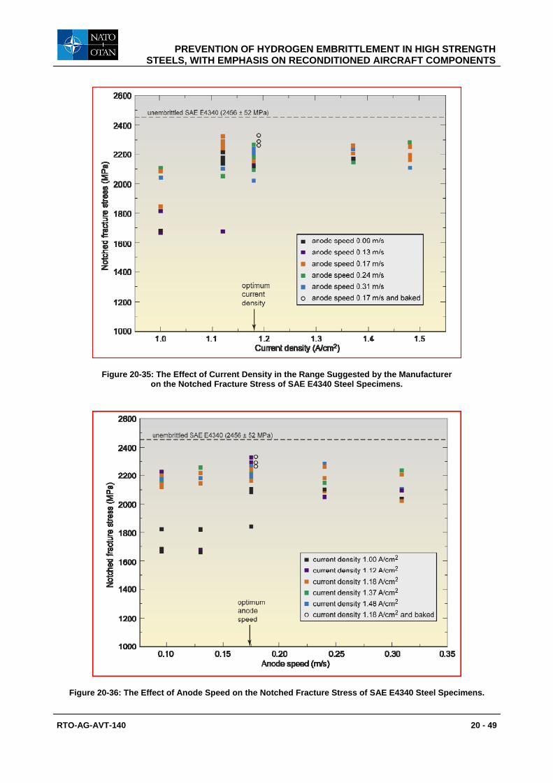
PREVENTION OF HYDROGEN EMBRITTLEMENT IN HIGH STRENGTH STEELS, WITH EMPHASIS ON RECONDITIONED AIRCRAFT COMPONENTS
RTO-AG-AVT-140 20 - 49
Figure 20-35: The Effect of Current Density in the Range Suggested by the Manufacturer on the Notched Fracture Stress of SAE E4340 Steel Specimens.
Figure 20-36: The Effect of Anode Speed on the Notched Fracture Stress of SAE E4340 Steel Specimens.

PREVENTION OF HYDROGEN EMBRITTLEMENT IN HIGH STRENGTH STEELS, WITH EMPHASIS ON RECONDITIONED AIRCRAFT COMPONENTS
20 - 50 RTO-AG-AVT-140
All of the SSRT specimens showed notched fracture stress reductions compared to the unembrittled fracture stress of 2456 ± 52 MPa. This was also observed in trials on Low Hydrogen Embrittlement (LHE) cadmium brush plated D6ac steel SSRT specimens [22]. More specifically, Figure 20-35 and Figure 20-36 indicate that the minimum reductions in fracture stress were obtained for SAE E4340 specimens plated under optimum conditions, whether subsequently baked or not. These results suggest that part of the fracture stress reductions may be due to some other phenomenon instead of IHE. One possibility is that the notch roots were slightly damaged by cleaning before plating.
The greatest reductions in SSRT notched fracture stresses were obtained from specimens plated with the lowest current densities and anode speeds. Some of these results were below the SSRT proposed acceptance criterion of 1840 MPa, which implies that specimens plated under these conditions might not have achieved the 200 hour SLT pass required by ASTM F519-06 (see Sections 20.4.1 and 20.4.6). This posed a potential problem for applying the Dalic Nickel Tungsten brush-plating process without subsequent baking. To check this potential problem, SLT notched tensile specimens were plated using the process manufacturer’s optimum and minimum current densities and anode speeds, and tested unbaked to see whether they met the 200 hour SLT pass required by ASTM F519-06. The SLT specimens plated under optimum conditions exceeded 818 hours without failure, while the specimens plated under minimum conditions exceeded 200 hours without failure. Hence it was concluded that all the plating conditions within the process manufacturer’s specifications would meet the ASTM F519-06 requirements without post-plating baking.
20.5.6.4 Conclusions and Recommendation
This “case history” demonstrated that the Dalic Nickel Tungsten brush plating process can be applied to ultrahigh strength steel without baking, since a combination of SSRT and SLT results showed that the ASTM F519-06 requirements were met. Consequently this plating process was approved for in situ repair, without post-plating baking, of worn flap and slat tracks of the tactical aircraft type. This “case history” also shows that using more than one IHE test can be very useful when evaluating the suitability of plating processes for high and ultrahigh strength steels.
20.6 CONCLUDING REMARKS
Internal Hydrogen Embrittlement (IHE) continues to be a problem for high strength steel aircraft components. IHE is nearly always associated with finishing processes for both new and reconditioned components. It is well understood that pickling, cathodic cleaning and electroplating involve the risk of IHE, and there are strict requirements for these processes. Nevertheless, procedural errors and inadequacies still occur. The case histories described in Section 20.5 illustrate some of these errors and inadequacies for reconditioned components, namely:
• Small service-induced corrosion pits and IHE cracks undetected before re-electroplating.
• Possible inadequate baking.
• Abusive grinding during clean-up of the steel surface.
• Poor electroplating.
• Incorrect cleaning.
Some of these deficiencies can also occur for new components. Other, less frequent, errors that have been found for new components include incorrect choice of steel [23] or hardness and strength ranges [24].
PREVENTION OF HYDROGEN EMBRITTLEMENT IN HIGH STRENGTH STEELS, WITH EMPHASIS ON RECONDITIONED AIRCRAFT COMPONENTS
RTO-AG-AVT-140 20 - 51
20.7 ACKNOWLEDGEMENTS
We wish to acknowledge Alan Cox and Willie Pollock (DSTO), and Frank Grooteman and Anne Oldersma (NLR) for their contributions to the case histories reported in this chapter. The late Willie Pollock also made seminal contributions to developing the Slow Strain Rate Tensile (SSRT) and Incremental Step-Load (ISL) test procedures for hydrogen embrittlement testing.
20.8 REFERENCES
[1] Wallace, W., Hoeppner, D.W. and Kandachar, P.V., “AGARD Corrosion Handbook, Volume 1, Aircraft Corrosion: Causes and Case Histories”, AGARDograph No. 278, Advisory Group for Aerospace Research and Development, Neuilly-sur-Seine, France, 1985.
[2] Akhurt, K.N. and Baker, T., “The Threshold Stress Intensity for Hydrogen-Induced Crack Growth”, Metallurgical Transactions, A12, pp. 1059-1070, 1981.
[3] Van Leeuwen, H.P., “A Quantitative Analysis of Hydrogen-Induced Cracking”, Doctor’s Thesis, Technical University Delft, Netherlands, June 1974.
[4] Frank, R.C., “Time-Dependent Effects of Hydrogen in Steel”, Internal Stresses and Fatigue in Metals, Editors G.M. Rassweiler and W.L. Grube, Elsevier Publishing Company, Amsterdam, Netherlands, pp. 411- 424, 1959.
[5] Thomas, R.L.S., Scully, J.R. and Gangloff, R.P., “Internal Hydrogen Embrittlement of Ultrahigh-Strength AERMET 100 Steel”, Metallurgical and Material Transactions A, Vol. 34A, pp. 327-344, 2003.
[6] Lynch, S.P., “Failure of Structures and Components by Environmentally Assisted Cracking”, Engineering Failure Analysis, Vol. 1, pp. 77-90, 1994.
[7] ASTM F 519-06, “Standard Test Method for Mechanical Hydrogen Embrittlement Evaluation of Plating/Coating Processes and Service Environments”, in: Annual Book of ASTM Standards, Section 15, Volume 15.03, ASTM International, West Conshohocken, PA, USA, 2007.
[8] ASTM F 1624-06, “Standard Test Method for Measurement of Hydrogen Embrittlement in Steel by the Incremental Step Loading Technique”, in: Annual Book of ASTM Standards, Section 15, Volume 15.03, ASTM International, West Conshohocken, PA, USA, 2007.
[9] National Aerospace Standard NASM1312-5, “Fastener Test Methods Method 5 Stress Durability”, Aerospace Industries Association of America, Inc., Washington, DC, USA, 1997.
[10] Troiano, A.R., “Delayed Failure of High Strength Steels”, Corrosion, Vol. 15, pp. 207t-212t, 1959.
[11] Pollock, W.J., “Statistical Treatment of Slow Strain Rate Data for Assessment of Hydrogen Embrittlement in Low Alloy High Strength Steel”, ARL-MAT-R-122, DSTO-AMRL, Fishermens Bend, Victoria, Australia, April 1990.
[12] Kindermann, M.R., Cave, B. and Arnott, D.R., “A Slow Strain-Rate Tensile Testing Machine”, ARL-MAT-TM-399, DSTO – AMRL, Fishermens Bend, Victoria, Australia, 1989.
[13] Gerrard, D.R., “The Determination of a Pass/Fail Criterion for the Slow Strain Rate Tensile (SSRT) Test for LHE Cadmium Electroplated High Strength Steel”, Milestone Report 6/02, Task AIR 99/076, DSTO, Melbourne, Australia, 2004.

PREVENTION OF HYDROGEN EMBRITTLEMENT IN HIGH STRENGTH STEELS, WITH EMPHASIS ON RECONDITIONED AIRCRAFT COMPONENTS
20 - 52 RTO-AG-AVT-140
[14] Cox, A.F. and Pollock, W.J., “Investigation of the Cracking in HS748 Propeller Blade Retaining Bolts”, ARL File BM2/03/17, Materials Division Ref. M89/83/AFC/WJP, DSTO, Melbourne, Australia, 1984.
[15] Barter, S.A., “Cracking in Mirage Main Landing Gear Half Fork Assemblies”, ARL File BM2/03/2, Materials Division Ref. M73/85/SAB, DSTO, Melbourne, Australia, 1986.
[16] Dodson, B., “Weibull Analysis”, ASQ Quality Press, Milwaukee, WI, USA, pp. 78-82, 1994.
[17] Nelson, W.B., “Applied Life Data Statistics, Series in Probability and Statistics”, Wiley & Sons, New York, NY, USA, pp. 370-386, 1982.
[18] During, E.D.D., “Corrosion Atlas: A Collection of Illustrated Case Histories”, Third, Expanded and Revised Edition, Elsevier Science Publishers B.V., Amsterdam, Netherlands, p. L [50], 1997.
[19] Pollock, W.J. and Grey, C., “Assessment of the Degree of Hydrogen Embrittlement Produced in Plated High-Strength 4340 Steel by Paint Strippers using Slow Strain Rate Testing”, Hydrogen Embrittlement: Prevention and Control, ASTM STP 962, Editor L. Raymond, American Society for Testing and Materials, Philadelphia, PA, USA, pp. 372-386, 1988.
[20] Movich, C.R., “Notched Bar-Bending Test”, Hydrogen Embrittlement Testing, ASTM STP 543, American Society for Testing and Materials, Philadelphia, PA, USA, pp. 64-73, 1974.
[21] Gerrard, D.R., Milestone Report 3/01, “Hydrogen Embrittlement of High Strength Steels from the Dalic Nickel Tungsten Brush Plating Process”, Task AIR 99/076, DSTO, 2002.
[22] Gerrard, D.R., “Hydrogen Embrittlement of D6ac Steel from the Dalic LHE Cadmium Brush Plating Process”, Milestone Report 4/01, Task AIR 99/076, DSTO, Melbourne, Australia, 2000.
[23] Barter, S.A., “F111C Crew Module Electrical Disconnects, Locking Lug Failure”, ARL File BM2/ 03/7, Materials Division Ref. M69/82/SAB, DSTO, Melbourne, Australia, 1984.
[24] Barter, S.A., “Chinook Drop Stop Interposer Bolt Failures”, ARL File BM2/03/11, Materials Division Ref. M49/82/SAB, DSTO, Melbourne, Australia, 1983.
Top Related