ZIC2410 User’s Guide Hardware Abstraction Layer API Reference
42
ZIC2410 User’s Guide Hardware Abstraction Layer API Reference 0005-05-08-19-001 (Rev A)
Transcript of ZIC2410 User’s Guide Hardware Abstraction Layer API Reference

ZIC2410 User’s Guide Hardware Abstraction Layer
API Reference 0005-05-08-19-001
(Rev A)

ZIC2410 Hardware Abstraction Layer API Reference
Rev A Document No. 0005-05-08-19-001 Page 2 of 42
Table of Contents
1 INTRODUCTION ................................................................................... 3
2 HARDWARE ABSTRACTION LAYER API REFERENCE .................... 4
2.1 HARDWARE ABSTRACTION LAYER API SUMMARY .................................... 4
2.2 INTRODUCTION TO FUNCTIONS .................................................................... 7
2.2.1 Definitions ........................................................................................................... 7 2.2.2 PHY ...................................................................................................................... 9 2.2.3 UART ...................................................................................................................17 2.2.4 TIMER COUNTER PWM .....................................................................................20 2.2.5 SPI .......................................................................................................................22 2.2.6 WDT ....................................................................................................................23 2.2.7 POWER CONTROL .............................................................................................23 2.2.8 SECURITY ..........................................................................................................25 2.2.9 FLASH.................................................................................................................32 2.2.10 ADC .....................................................................................................................33 2.2.11 KEYSCAN ...........................................................................................................34 2.2.12 LCD .....................................................................................................................35 2.2.13 QUAD DECODER ...............................................................................................39 2.2.14 UTIL ....................................................................................................................39
3 REVISION HISTORY .......................................................................... 42

ZIC2410 Hardware Abstraction Layer API Reference
Rev A Document No. 0005-05-08-19-001 Page 3 of 42
1 INTRODUCTION The ZIC2410 is a complete single-chip solution for wireless ZigBee-based applications which is both IEEE802.15.4 and ZigBee compliant. The ZIC2410 is ideal for ZigBee applications such as home control, sensor networks and automatic meter reading. It is comprised of a RF transceiver with baseband modem, a hardwired MAC and an embedded 8051 microcontroller complete with internal Flash memory for application program storage. Also included are several general-purpose I/O pins and a laundry-list of processor peripherals such as timer/counters, serial interfaces and a four channel Analog-to-Digital Converter (ADC). The ZIC2410 was design with low power applications in mind by offering four different sleep modes and operating voltages below two Volts.
This document describes the functions used to control the peripherals of the ZIC2410. The following primitive functions are included in the Hardware Abstraction Layer API:
ZigBee & IEEE 802.15.4 Radio Initialization
Radio Control Utility functions to set Channel, RF Output Power and Energy Spectrum.
API for peripheral control, UART, Interrupt, PWM, SPI, Watchdog Timer (WDT), ADC and Clock.
Debug Utility
Security
Virtual Timer
Power Management
Figure 1 below shows the functional block diagram of ZIC2410.
Figure 1 – Functional Block Diagram of ZIC2410

ZIC2410 Hardware Abstraction Layer API Reference
Rev A Document No. 0005-05-08-19-001 Page 4 of 42
2 HARDWARE ABSTRACTION LAYER API REFERENCE
2.1 HARDWARE ABSTRACTION LAYER API SUMMARY
Table 1 – Hardware Abstraction Layer API Summary
Function Description
Category: PHY (Section 2.2.2) ZHAL_3V_LOGIC_INIT() Used when initializing the register of 3V-LOGIC block.
ZHAL_HW_INIT() Used in selecting voltage and in setting core crystal frequency of crystal of the ZIC2410.
ZHAL_REGULATOR_SET() Sets the output voltage of regulator.
ZHAL_MODEM_INIT() Initializes the ZIC2410’s RF transceiver.
ZHAL_MAC_CTRL_SET() Sets the MACCTRL register.
ZHAL_AUTO_CRC_SET() Sets the AutoCRC in MACCTRL register.
ZHAL_ADDR_DECODE_SET() Sets the AddressDecode in MACCTRL register.
ZHAL_COORDINATOR_SET() Sets the PAN Coordinator function in MAC CTRL register (address: 0x2191)
ZHAL_CHANNEL_SET() Sets the RF channel.
ZHAL_PAN_ID_SET() Sets the PAN ID.
ZHAL_SHORT_ADDR_SET() Sets the Short Address.
ZHAL_IEEE_ADDR_SET() Sets the IEEE Address.
ZHAL_TXPOWER_SET() Sets the RF Output Power.
ZHAL_ED_dBm_GET() Returns the result of Energy Detection in dBm
ZHAL_ED_LEVEL_GET() Returns the result of Energy Detection in level units.
ZHAL_TRSW_SET() Sets the TRSW/TRSWB.
ZHAL_TEST_TXOUT() Sets the Test Mode for RF characteristics.
ZHAL_DATARATE_SET() Sets the Data Rate of RF transmission.
ZHAL_MAKE_TXFIFO() Stores the packet ready to be transmitted in TXFIFO.
ZHAL_SEND_TXFIFO() Transmits the packet stored in TXFIFO.
ZHAL_SEND_ACK() Transmits an ACK (Acknowledgement).
ZHAL_RF_INT_SET() Arms the RF Interrupt.
ZHAL_RF_INT_CLEAR() Clears the pending RF interrupts.
ZHAL_EXT0_INT_SET() Sets the EXT0 Interrupt.
ZHAL_EXT1_INT_SET() Sets the EXT1 Interrupt.
ZHAL_PORT0_INOUT_SET() Sets the GPIO Port0.
ZHAL_PORT1_INOUT_SET() Sets the GPIO Port1.
ZHAL_PORT3_INOUT_SET() Sets the GPIO Port3.
ZHAL_SYSTEM_INTERRUPT() Sets all Interrupts (EA).
ZHAL_VFIFO_MUX_SET() Sets the Interface block for Voice FIFO.
ZHAL_CLOCK_BLOCK_SET() Applies the clock to the Codec and AES block.
ZHAL_CLOCK_PLL_SET() Uses the CLKPLL.
ZHAL_CLOCK_16MHz_SET() Sets the clock to 16MHz mode.
Category: UART (Section 2.2.3) ZHAL_UART0_SET() Sets the UART0 Interrupt.
ZSYS_UART0_PUT() Stores data in the UART0 TX Buffer.
ZSYS_UART0_GET() Gets data from the UART0 RX Buffer.
ZSYS_UART0_TXLEN() Returns the number of bytes in the UART0 TX Buffer.
ZSYS_UART0_RXLEN() Returns the number of bytes in the UART0 RX Buffer.
ZSYS_UART0_TX_WORKING() Returns the result of transmission of the UART0.
ZHAL_UART1_SET() Sets the UART1 Interrupt.
ZSYS_UART1_PUT() Stores data to the UART1 TX Buffer.
ZSYS_UART1_GET() Get data from the UART1 RX Buffer.
ZSYS_UART1_TXLEN() Return the number of bytes in the UART1 TX Buffer.
ZSYS_UART1_RXLEN() Return the number of bytes in the UART1 RX Buffer.

ZIC2410 Hardware Abstraction Layer API Reference
Rev A Document No. 0005-05-08-19-001 Page 5 of 42
Function Description
ZSYS_UART1_TX_WORKING() Returns the result of transmission of the UART1.
Category: TIMER COUNTER PWM (Section 2.2.4) ZHAL_TIMER0_SET() Sets the TIMER0 Interrupt.
ZHAL_TIMER1_SET() Sets the TIMER1 Interrupt.
ZHAL_TIMER2_SET() Sets the TIMER2 Interrupt.
ZHAL_TIMER3_SET() Sets the TIMER3 Interrupt.
ZHAL_COUNTER0_SET() Sets the COUNTER0 Interrupt.
ZHAL_COUNTER1_SET() Sets the COUNTER1 Interrupt.
ZHAL_PWM_SET() Sets the PWM mode.
Category: SPI (Section 2.2.5) ZHAL_SPI_SET() Sets the SPI interrupt.
ZHAL_SPI_MASTER() Generates the SPI Cycle by SPI Master.
ZHAL_SPI_SLAVE() Processes the SPI Cycle by SPI Slave.
Category: WDT(Section 2.2.6) ZHAL_WDT_SET() Sets the Watchdog Timer.
ZHAL_WDT_RESTART() Clears the Watchdog Counter.
ZSYS_WDT_SET() Sets the Watchdog Timer period.
Category: POWER CONTROL (Section 2.2.7) ZHAL_PWRMNGT_SET() RF Block On/Off.
ZHAL_IDLE_MODE() Enters IDLE mode.
ZHAL_PD_SET() Enters Power-Down mode.
ZSYS_PowerDown() Enters Power-Down mode by setting Wakeup period to second unit.
Category: SECURITY (Section 2.2.8) ZHAL_SEC_KEY_SET() Sets the Security Keys.
ZHAL_SEC_TXNONCE_KEY_SEQ_SET()
Sets the Key Sequence Number of TX NONCE within materials used in security.
ZHAL_SEC_RXNONCE_KEY_SEQ_SET()
Sets the Key Sequence Number of RX NONCE within materials used in security.
ZHAL_SEC_TXNONCE_KEY_SEQ_GET()
Reads the Key Sequence Number of TX NONCE within materials used in security.
ZHAL_SEC_RXNONCE_KEY_SEQ_GET()
Reads the Key Sequence Number of RX NONCE within materials used in security.
ZHAL_SEC_TXNONCE_FRAME_CNT_SET()
Sets the Frame Counter of TX NONCE within materials used in security.
ZHAL_SEC_RXNONCE_FRAME_CNT_SET()
Sets the Frame Counter of RX NONCE within materials used in security.
ZHAL_SEC_TXNONCE_FRAME_CNT_GET()
Reads the Frame Counter of TX NONCE within materials used in security.
ZHAL_SEC_RXNONCE_FRAME_CNT_GET()
Reads the Frame Counter of RX NONCE within materials used in security.
ZHAL_SEC_TXNONCE_EXT_ADDR_SET()
Sets the Extend Address of TX NONCE within materials used in security.
ZHAL_SEC_RXNONCE_EXT_ADDR_SET()
Sets the Extend Address of RX NONCE within materials used in security.
ZHAL_SEC_TXKEY_CHOICE() Selects the key used in Outgoing Security Operation.
ZHAL_SEC_RXKEY_CHOICE() Selects the key used in Incoming Security Operation.
ZHAL_SEC_SECM_SET() Sets the length of the authentication field.
ZHAL_SEC_MODE_SET() Sets the Security mode.
ZHAL_SEC_TXL_SET() Selects the L value used in encryption.
ZHAL_SEC_RXL_SET() Selects the L value used in decryption.
ZHAL_SEC_SAES() Executes Stand Alone AES.
ZIC2410 Hardware Abstraction Layer API Reference
Rev A Document No. 0005-05-08-19-001 Page 6 of 42
Function Description
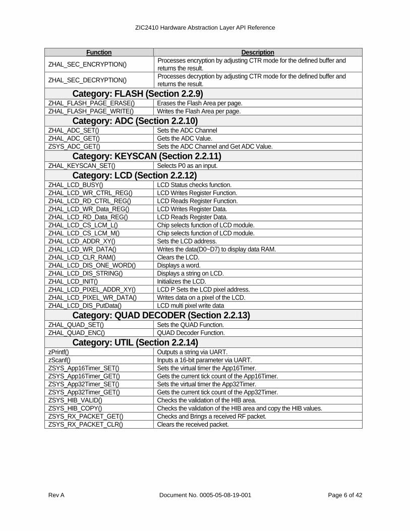
ZHAL_SEC_ENCRYPTION() Processes encryption by adjusting CTR mode for the defined buffer and returns the result.
ZHAL_SEC_DECRYPTION() Processes decryption by adjusting CTR mode for the defined buffer and returns the result.
Category: FLASH (Section 2.2.9) ZHAL_FLASH_PAGE_ERASE() Erases the Flash Area per page.
ZHAL_FLASH_PAGE_WRITE() Writes the Flash Area per page.
Category: ADC (Section 2.2.10) ZHAL_ADC_SET() Sets the ADC Channel
ZHAL_ADC_GET() Gets the ADC Value.
ZSYS_ADC_GET() Sets the ADC Channel and Get ADC Value.
Category: KEYSCAN (Section 2.2.11) ZHAL_KEYSCAN_SET() Selects P0 as an input.
Category: LCD (Section 2.2.12) ZHAL_LCD_BUSY() LCD Status checks function.
ZHAL_LCD_WR_CTRL_REG() LCD Writes Register Function.
ZHAL_LCD_RD_CTRL_REG() LCD Reads Register Function.
ZHAL_LCD_WR_Data_REG() LCD Writes Register Data.
ZHAL_LCD_RD_Data_REG() LCD Reads Register Data.
ZHAL_LCD_CS_LCM_L() Chip selects function of LCD module.
ZHAL_LCD_CS_LCM_M() Chip selects function of LCD module.
ZHAL_LCD_ADDR_XY() Sets the LCD address.
ZHAL_LCD_WR_DATA() Writes the data(D0~D7) to display data RAM.
ZHAL_LCD_CLR_RAM() Clears the LCD.
ZHAL_LCD_DIS_ONE_WORD() Displays a word.
ZHAL_LCD_DIS_STRING() Displays a string on LCD.
ZHAL_LCD_INIT() Initializes the LCD.
ZHAL_LCD_PIXEL_ADDR_XY() LCD P Sets the LCD pixel address.
ZHAL_LCD_PIXEL_WR_DATA() Writes data on a pixel of the LCD.
ZHAL_LCD_DIS_PutData() LCD multi pixel write data
Category: QUAD DECODER (Section 2.2.13) ZHAL_QUAD_SET() Sets the QUAD Function.
ZHAL_QUAD_ENC() QUAD Decoder Function.
Category: UTIL (Section 2.2.14) zPrintf() Outputs a string via UART.
zScanf() Inputs a 16-bit parameter via UART.
ZSYS_App16Timer_SET() Sets the virtual timer the App16Timer.
ZSYS_App16Timer_GET() Gets the current tick count of the App16Timer.
ZSYS_App32Timer_SET() Sets the virtual timer the App32Timer.
ZSYS_App32Timer_GET() Gets the current tick count of the App32Timer.
ZSYS_HIB_VALID() Checks the validation of the HIB area.
ZSYS_HIB_COPY() Checks the validation of the HIB area and copy the HIB values.
ZSYS_RX_PACKET_GET() Checks and Brings a received RF packet.
ZSYS_RX_PACKET_CLR() Clears the received packet.

ZIC2410 Hardware Abstraction Layer API Reference
Rev A Document No. 0005-05-08-19-001 Page 7 of 42
2.2 INTRODUCTION TO FUNCTIONS
2.2.1 Definitions Name Type Description
2.2.1.1 Type Definition
UINT8 8 bit unsigned character
UINT16 16 bit unsigned short integer
UINT32 32 bit unsigned long integer
INT8 8 bit signed character
INT16 16 bit signed short integer
INT32 32 bit signed long integer
2.2.1.2 Struct of PACKET_INFO
PanID UINT16 16 bit Personal Area Network ID
SrcAddr UINT16 16 bit Source Address
DstAddr UINT16 16 bit Destination Address
DSN UINT8 Sequence Number Field
pBuf UINT8 * A Pointer for MSDU (data to transmit)
BufLen UINT8 the length of MSDU (data to transmit)
AckReq UINT8 Ack Receiving: 1=is requested. 0=is not requested
TxOOB UINT8 OOB (Out-Of-Band) code defined by the user
0=Not use OOB. Follow IEEE 802.15.4 frame structure. 1 ~ 15=OOB (Out-Of-Band) code defined by the user.
2.2.1.3 Struct of MAC_PKT
LEN UINT8 the length of a received packet
HLen UINT8 the length of a received packet header
MLen UINT8 the length of a received packet MSDU
FC_L UINT8 the LSB byte of Frame Control field
FC_H UINT8 the MSB byte of Frame Control field
DSN UINT8 Sequence Number Field
RxOOB UINT8 OOB(Out-Of-Band) code
DstMode UINT8 Destination Addressing mode. 0=None, 2=Short, 3=Extended
DstPanID UINT16 16bit Destination PanID
DstShortAddr UINT16 1 6bit Destination Short Address. Valid if DstMode=2
DstExtAddr UINT8 Array
64bit Destination Extended Address. Valid if DstMode=3.the MSB of DstExtAddr has the MSB of IEEE Address
SrcMode UINT8 Source Addressing mode 0=None, 2=Short, 3=Extended
SrcPanID UINT16 16bit Source PanID
SrcShortAddr UINT16 16bit Source Short Address. Valid if SrcMode=2
SrcExtAddr UINT8 Array 64bit Source Extended Address. Valid if SrcMode=3 the MSB of SrcExtAddr has the MSB of IEEE Address
MSDU UINT8 Array
MSDU(data to transmit)
FCS UINT8 Array
Frame Check Sequence field for CRC
RSSI_LQI UINT8 RSSI in LQI. 0=-100 dBm, 255=0dBm
RSSI_dBm INT8 RSSI in dBm
2.2.1.4 Struct of HW_INFORMATION
IEEE_ADDR UINT8 Array
64bit IEEE Address. the MSB of IEEE_ADDR has the MSB of IEEE address.
ChipID UINT8
PowerID UINT8 0x15=1.5V, 0x18=1.8V
ModemID UINT8 0=250Kbps, 1=500Kbps, 2=1Mbps

ZIC2410 Hardware Abstraction Layer API Reference
Rev A Document No. 0005-05-08-19-001 Page 8 of 42
Name Type Description
StackVersion UINT8 0x10=Zigbee2004, 0x11=ZigBee2005 0x12=ZigBee2006, 0x13=ZigBee2007
Channel UINT8 Initial RF Channel
PanID UINT16 16bit Personal Area Network ID
NwkAddr UINT16 16bit Short(or Network) Address
SecurityLevel UINT8 0=No Security, 1=MIC32, 2=MIC64, 3=MIC128 4=ENC, 5=ENCMIC32, 6=ENCMIC64, 7=ENCMIC128
PreConfigMode UINT8 Pre-configured Mode Value
NwkKey UINT8 Array
Network Key for Security the MSB of NwkKey has the MSB of Key
Reserved_0 UINT8 Array
16Byte reserved buffer
EPID UINT8 Array
8Byte Extended PAN-ID
Reserved_1 UINT8 Array
12Byte reserved buffer
CSUM UINT8 CheckSum Value
Space UINT8 Array
448Byte undefined buffer

ZIC2410 Hardware Abstraction Layer API Reference
Rev A Document No. 0005-05-08-19-001 Page 9 of 42
2.2.2 PHY
2.2.2.1 ZHAL_3V_LOGIC_INIT()
Syntax void ZHAL_3V_LOGIC_INIT();
Description Initializes the register of the 3V-LOGIC block. Since this register is not initialized on reset after exiting from Power-Down mode 2 and 3, this function should be called in the boot-up.
Parameter Void
Return Value Void
Example
void main()
{
ZSYS_WDT_SET(0, 0); //Initialize modem in boot-up.
ZHAL_3V_LOGIC_INIT();
ZHAL_HW_INIT(0,0); //H/W Initialization
ZHAL_MODEM_INIT();
...
}
See Also ZSYS_PowerDown()
Remark #include “PHY.h”
2.2.2.2 ZHAL_HW_INIT()
Syntax void ZHAL_HW_INIT(UINT8 Ena19MHz, UINT8 VoltageChange);
Description Selects the voltage and core crystal frequency setting of the ZIC2410. Sets the frequency of crystal by calling ZHAL_CLOCK_PLL_SET() function and sets the voltage by calling ZHAL_REGULATOR_SET() function.
Parameter
▪ Ena19MHz: 1=Use 19.2MHz crystal; 0=Use 16 MHz crystal.
▪ VoltageChange: 1=Changes the voltage used in core from 1.5V to 1.8V or from 1.8V to 1.5V. 0=Does not change the voltage used in core.
Return Value Void
Example
void main()
{
ZSYS_WDT_SET(0, 0); //Initialize modem in boot-up.
ZHAL_3V_LOGIC_INIT();
ZHAL_HW_INIT(0,0); //H/W Initialization
ZHAL_MODEM_INIT();
...
}
See Also HAL_CLOCK_PLL_SET(), ZHAL_REGULATOR_SET()
Remark #include “PHY.h”
2.2.2.3 ZHAL_REGULATOR_SET()
Syntax void ZHAL_REGULATOR (UINT8 ChangeAnalog, UINT8 ChangeDigital);
Description Sets the output voltage of regulator which is applied to the core.
Parameter
▪ ChangeAnalog Block Regulator: 1=Changes the output to 1.5V (MSV pin=HIGH) or 1.8V (MSV pin=LOW). 0=Changes the output to 1.8V (MSV pin=HIGH) or 1.5V (MSV pin=LOW.)
▪ ChangeDigital Block Regulator 1=Changes the output to 1.5V (MSV pin=HIGH) or 1.8V (MSV pin=LOW). 0=Changes the output to 1.8V (MSV pin=HIGH) or 1.5V (MSV pin=LOW.)
Return Value Void
Example
void main()
{
ZHAL_REGULATOR_SET(1, 1); //Change the voltage.
ZHAL_REGULATOR_SET(0, 0); //Does not change the voltage.
}

ZIC2410 Hardware Abstraction Layer API Reference
Rev A Document No. 0005-05-08-19-001 Page 10 of 42
See Also ZHAL_HW_INIT()
Remark #include “PHY.h”
2.2.2.4 ZHAL_MODEM_INIT()
Syntax void ZHAL_MODEM_INIT();
Description Enables the use of the RF function by initializing Modem block of ZIC2410 including RF circuit. This function should be called in boot-up.
Parameter Void
Return Value Void
Example
void main()
{
ZSYS_WDT_SET(0, 0); //Initialize modem in boot-up .
ZHAL_MODEM_INIT();
...
}
See Also ZHAL_WDT_SET(), ZHAL_WDT_RESTART()
Remark #include “PHY.h”
2.2.2.5 ZHAL_MAC_CTRL_SET()
Syntax void ZHAL_MAC_CTRL_SET(UINT8 MacCtrl);
Description Set the value of MACCTRL (0x2191) register.
Parameter ▪ MacCtrl:
bit [0]: 1=Enable AutoAck; bit [1]: 1=Enable AutoCRC: bit [2]: 1=Enable Address Decode; bit [3]: 1=Enable PAN Coordinator: bit [4]: 1=Enable Prevent Invalid Ack.
Return Value Void
Example ZHAL_MAC_CTRL_SET(0x06);
See Also ZHAL_AUTO_CRC_SET() ZHAL_ADDR_DECODE_SET()
Remark
#include “PHY.h” It is recommend that AutoCRC bit and Address Decode bit are always enabled. PAN Coordinator bit is used when Address Decode bit is valid and it should be enabled only when a device acts as a PAN Coordinator in an IEEE 802.15.4 network. When this function is enabled, some frames, whose address type is unique, are accepted in address decoding.
2.2.2.6 ZHAL_AUTO_CRC_SET
Syntax void ZHAL_AUTO_CRC_SET(UINT8 Ena);
Description Sets the AUTO_CRC function of MACCTRL (0x2191) register.
Parameter ▪ Ena: 1=AutoCRC enable; 0=AutoCRC disable
Return Value Void
Example
See Also ZHAL_MAC_CTRL_SET()
Remark #include “PHY.h”
2.2.2.7 ZHAL_ADDR_DECODE_SET()
Syntax void ZHAL_ADDR_DECODE_SET(UINT8 Ena);
Description Sets the Address decode function of MACCTRL(0x2191) register.
Parameter ▪ Ena: 1=Address Decode enable; 0=Address Decode disable
Return Value Void
Example
See Also ZHAL_MAC_CTRL_SET()
Remark #include “PHY.h”
2.2.2.8 ZHAL_COORDINATOR_SET()
Syntax void ZHAL_COORDINATOR_ SET(UINT8 Ena);
Description Sets the Pan Coordinator function in MAC CTRL register (0x2191). When this function is activated, Address Decode function should also be activated. Otherwise, the Pan Coordinator function will not work. Receives some packets which only a Coordinator can receive.
Parameter ▪ Ena: 1=Activate Pan Coordinator: 0=Inactivate Pan Coordinator
Return Value Void

ZIC2410 Hardware Abstraction Layer API Reference
Rev A Document No. 0005-05-08-19-001 Page 11 of 42
Example
See Also ZHAL_MAC_CTRL_SET()
Remark #include “PHY.h”
2.2.2.9 ZHAL_CHANNEL_SET()
Syntax void ZHAL_CHANNEL_SET(UINT8 Chan);
Description Sets the RF channel.
Parameter RF Channel (11 ~ 26)
Return Value Void
Example
See Also ZHAL_PAN_ID_SET(), ZHAL_SHORT_ADDR_SET()
Remark Includes “PHY.h”. This function doesn’t have return value if PLL is not locked after RF channel setting.
2.2.2.10 ZHAL_PAN_ID_SET()
Syntax void ZHAL_PAN_ID_SET(UINT16 ID);
Description A network has a unique ID which distinguishes that network from others called a PAN ID. Sets the PAN ID.
Parameter ID PAN ID of network
Return Value Void
Example
See Also ZHAL_CHANNEL_SET(), ZHAL_SHORT_ADDR_SET()
Remark #include “PHY.h”
2.2.2.11 ZHAL_SHORT_ADDR_SET()
Syntax void ZHAL_SHORT_ADDR_SET(UINT16 Addr);
Description Each device in a network has its own Short Address (or Network Address). Sets the Short Address.
Parameter Addr Short Address of network
Return Value Void
Example
See Also ZHAL_CHANNEL_SET(), ZHAL_PAN_ID_SET()
Remark #include “PHY.h”
2.2.2.12 ZHAL_IEEE_ADDR_SET()
Syntax void ZHAL_IEEE_ADDR_SET(UINT8 *pAddr);
Description A device used in IEEE802.15.4 or ZigBee network should have the unique 64-bit IEEE address provided by the IEEE. Sets the IEEE address.
Parameter pAddr A pointer for IEEE address of 8-byte. LSB of buffer is LSB of IEEE address.
Return Value Void
Example
//Set the IEEE address (0x0123456789ABCDEF)
UINT8 IEEE_BUFF[8];
IEEE_BUFF[7]=0x01;
IEEE_BUFF[6]=0x23;
IEEE_BUFF[5]=0x45;
IEEE_BUFF[4]=0x67;
IEEE_BUFF[3]=0x89;
IEEE_BUFF[2]=0xAB;
IEEE_BUFF[1]=0xCD;
IEEE_BUFF[0]=0xEF;
ZHAL_IEEE_ADDR_SET(&IEEE_BUFF[0]);
See Also
Remark #include “PHY.h”
2.2.2.13 ZHAL_TXPOWER_SET()
Syntax void ZHAL_TXPOWER_SET(UINT8 PowerLevel);
Description Sets the RF output power (0~18)

ZIC2410 Hardware Abstraction Layer API Reference
Rev A Document No. 0005-05-08-19-001 Page 12 of 42
Parameter
PowerLevel 0=Max Power (dBm) 1=Max Power – 1 (dBm) 2=Max Power – 2 (dBm) 3=Max Power – 3 (dBm) 4=Max Power – 4 (dBm) 5=Max Power – 5 (dBm) 6=Max Power – 6 (dBm) 7=Max Power – 7 (dBm) 8=Max Power – 8 (dBm) 9=Max Power – 9 (dBm) 10=Max Power – 10 (dBm) 11=Max Power – 15 (dBm) 12=Max Power – 17 (dBm) 13=Max Power – 20 (dBm) 14=Max Power – 25 (dBm) 15=Max Power – 30 (dBm) 16=Max Power – 40 (dBm) 17=Max Power – 50 (dBm) 18=Max Power – 60 (dBm)
Return Value Void
Example
See Also ZHAL_TEST_TXOUT()
Remark #include “PHY.h”
2.2.2.14 ZHAL_ED_dBm_GET()
Syntax INT8 ZHAL_ED_dBm_GET();
Description Results in dBm after performing ED (Energy Detection) of an RF channel.
Parameter Void
Return Value ED result (dBm, -128 ~ 127)
Example
INT8 ED_dBm;
ED_dBm=ZHAL_ED_dBm_GET();
zPrintf (1, “\n Current ED is %d dBm”,(short) ED_dBm);
See Also ZHAL_ED_LEVEL_GET()
Remark #include “PHY.h”
2.2.2.15 ZHAL_ED_LEVEL_GET()
Syntax UINT8 ZHAL_ED_LEVEL_GET();
Description Results in level units (0~255) after performing ED (Energy Detection) of an RF channel.
255 means 0dBm and 0 means -100dBm.
Parameter Void
Return Value ED result(level unit, 0 ~ 255)
Example
UINT8 ED_Level;
ED_Level=ZHAL_ED_dBm_GET();
zPrintf (1, “\n Current ED is %u”,(short) ED_Level);
See Also ZHAL_ED_dBm_GET()
Remark #include “PHY.h” dBm=-100 + (100/255) * ED_Level
2.2.2.16 ZHAL_TRSW_SET()
Syntax void ZHAL_TRSW_SET(UINT8 Ena);
Description Sets P1.7 or P1.6 of the GPIO in ZIC2410 to TRSW or TRSWB signal respectively. TRSW=HIGH for TX;=LOW for RX. TRSWB=LOW for TX:=HIGH for RX.
Parameter ▪ Ena:
Bit [0]: 1=TRSW (P1.7) enable: 0=TRSW disable Bit [1]: 1=TRSWB (P1.6) enable; 0=TRSWB disable
Return Value Void

ZIC2410 Hardware Abstraction Layer API Reference
Rev A Document No. 0005-05-08-19-001 Page 13 of 42
Example
See Also
Remark #include “PHY.h” TRSW and TRSWB are used for controlling external amplifier. When TRSW/TRSWB is enabled, corresponding port cannot be used as GPIO port.
2.2.2.17 ZHAL_TEST_TXOUT()
Syntax void ZHAL_TEST_TXOUT(UINT8 Ena, UINT8 ModulateEn);
Description Output Continuous Carrier Wave or Modulated Spectrum to test the RF characteristics.
Parameter ▪ Ena: 1=Test output enable; 0=Test output disable
▪ ModulateEn: 1=Modulated Spectrum; 0=Continuous Carrier Wave
Return Value Void
Example
//Output Continuous Carrier Wave
ZHAL_TEST_TXOUT(1, 0);
//Output Modulated Spectrum
ZHAL_TEST_TXOUT(1, 1);
//Return to Normal Mode
ZHAL_TEST_TXOUT(0,0);
See Also ZHAL_TXPOWER_SET()
Remark #include “PHY.h”
2.2.2.18 ZHAL_DATARATE_SET()
Syntax void ZHAL_DATARATE_SET(UINT8 Rate);
Description Set data rate of RF.
Parameter ▪ Rate: 0=250Kbps, 1=500Kbps, 2=1Mbps
Return Value Void
Example
See Also
Remark #include “PHY.h”
2.2.2.19 ZHAL_MAKE_TXFIFO()
Syntax void ZHAL_MAKE_TXFIFO(PACKET_INFO *pPACKET);
Description Stores the packet to be transferred in the TXFIFO(LSB first).
Parameter ▪ pPACKET A pointer for the structure, which includes the information of packet to be transferred.
Return Value Void
Example
PACKET_INFO TxMPK;
UINT8 TxBUF[16];
TxBUF[0]=0x00;
...
TxBUF[15]=0x0F;
TxMPK.BufLen=16;
TxMPK.pBuf=&TxBUF[0];
TxMPK.PanID=0xABCD;
TxMPK.SrcAddr=0x0001;
TxMPK.DstAddr=0x0002;
TxMPK.AckReq=0x01;
TxMPK.DSN=0xA0;
TxMPK.TxOOB=0x00;
ZHAL_MAKE_TXFIFO(&TxMPK);
See Also ZHAL_MAKE_TXFIFO_CIRCULAR(), ZHAL_SEND_TXFIFO()

ZIC2410 Hardware Abstraction Layer API Reference
Rev A Document No. 0005-05-08-19-001 Page 14 of 42
Remark
#include “PHY.h” OOB code is carried in the field which is not used in IEEE802.15.4 frame header. Used for indicating the code defined by a user because of special purpose. However, generally it is recommended not to use it. 0=Not use OOB. Follow IEEE 802.15.4 frame structure exactly. 1 ~ 15=OOB (Out-Of-Band) code defined by a user.
2.2.2.20 ZAHL_SEND_TXFIFO()
Syntax UINT8 ZHAL_SEND_TXFIFO()
Description Transmit the packet in TXFIFO(LSB first).
Parameter Void
Return Value
The result of transmission is as follows. 0x00:Success 0xE1: Fail to access the RF channel. 0xE9: Fail to receive ACK frame.
Example
UINT8 STA;
PACKET_INFO TxMPK;
//TxMPK Setting
ZHAL_MAKE_TXFIFO(&TxMPK, 0x00);
STA=ZHAL_SEND_TXFIFO();
if(STA==0xE1) zPrintf(1,“\n Chan Access Fail”);
else if(STA==0xE9) zPrintf(1,“\n No Ack Fail”);
else zPrintf(1,“\n SUCCESS”);
See Also ZHAL_MAKE_TXFIFO(), ZHAL_SEND_TXFIFO_CIRCULAR()
Remark #include “PHY.h” Should be used with ZHAL_MAKE_TXFIFO() function.
2.2.2.21 ZHAL_SEND_ACK()
Syntax void ZHAL_SEND_ACK(UINT8 FP, UINT8 DSN);
Description Transmit Ack frame.
Parameter ▪ FP: 1=There is a pended frame. 0=There is no a pended frame. ▪ DSN: the Data Sequence Number of the Ack frame.
Return Value Void
Example
See Also
Remark #include “PHY.h”
2.2.2.22 ZHAL_RF_INT_SET()
Syntax void ZHAL_RF_INT_SET(UINT8 IntEna, UINT8 Priority);
Description Set RF interrupt.
Parameter ▪ IntEna: 1=Interrupt enable, 0=Interrupt disable ▪ Priority: 1=High priority, 0=Low priority
Return Value Void
Example
See Also
Remark #include “PHY.h”
2.2.2.23 ZHAL_RF_INT_CLEAR()
Syntax void ZHAL_RF_INT_CLEAR();
Description Clear pended RF interrupts. Call it before enabling RF interrupt.
Parameter
Return Value Void
Example ZHAL_RF_INT_CLEAR(); ZHAL_RF_INT_SET(1, 0);
See Also
Remark #include “PHY.h”
2.2.2.24 ZHAL_EXT0_INT_SET()
Syntax void ZHAL_EXT0_INT_SET(UINT8 IntEna, UINT8 Priority, UINT8 TypeEdge);

ZIC2410 Hardware Abstraction Layer API Reference
Rev A Document No. 0005-05-08-19-001 Page 15 of 42
Description Set the external interrupt0.
Parameter ▪IntEna: 1=Interrupt enable, 0=Interrupt disable ▪Priority: 1=High priority, 0=Low priority ▪TypeEdge: 1=Edge type interrupt, 0=Level type interrupt
Return Value Void
Example
See Also ZHAL_EXT1_INT_SET()
Remark #include “PHY.h”
2.2.2.25 ZHAL_EXT1_INT_SET()
Syntax void ZHAL_EXT1_INT_SET(UINT8 IntEna, UINT8 Priority, UINT8 TypeEdge);
Description Set the external interrupt1.
Parameter ▪IntEna: 1=Interrupt enable, 0=Interrupt disable ▪Priority: 1=High priority, 0=Low priority ▪TypeEdge: 1=Edge type interrupt, 0=Level type interrupt
Return Value void
Example
See Also ZHAL_EXT0_INT_SET()
Remark #include “PHY.h”
2.2.2.26 ZHAL_PORT0_INOUT_SET()
Syntax void ZHAL_PORT0_INOUT_SET(UINT8 Port, UINT8 OutEnable);
Description Set GPIO port0.
Parameter
▪Port: Port number(n). 0~7:P0.n , 0xA:all P0 ▪OutEnable:
1=Set as output port. Internal amplifier is enabled and Pull-up resistance is disconnected. 0=Set as input port. Internal amplifier is disabled and Pull-up resistance is connected.
Return Value Void
Example
See Also ZHAL_PORT1_INOUT_SET(), ZHAL_PORT3_INOUT_SET()
Remark #include “PHY.h”
2.2.2.27 ZHAL_PORT1_INOUT_SET()
Syntax void ZHAL_PORT1_INOUT_SET(UINT8 Port, UINT8 OutEnable);
Description Set GPIO port1.
Parameter
▪Port: Port number(n). 0~7:P1.n , 0xA:all P1 (P1_7 is always output.) ▪OutEnable:
1=Set as output port. I nternal amplifier is enabled and Pull-up resistance is disconnected. 0=Set as input port. Internal amplifier is disabled and Pull-up resistance is connected.
Return Value Void
Example
See Also ZHAL_PORT0_INOUT_SET(), ZHAL_PORT3_INOUT_SET()
Remark #include “PHY.h”
2.2.2.28 ZHAL_PORT3_INOUT_SET()
Syntax void ZHAL_PORT3_INOUT_SET(UINT8 Port, UINT8 OutEnable);
Description Set GPIO port3.
Parameter
▪Port: Port number(n). 0~7:P3.n , 0Xa:all P3 ▪OutEnable
1=Set as output port. Internal amplifier is enabled and Pull-up resistance is disconnected. 0=Set as input port. Internal amplifier is disabled and Pull-up resistance is connected.
Return Value Void
Example
See Also ZHAL_PORT0_INOUT_SET(), ZHAL_PORT1_INOUT_SET()
Remark #include “PHY.h”

ZIC2410 Hardware Abstraction Layer API Reference
Rev A Document No. 0005-05-08-19-001 Page 16 of 42
2.2.2.29 ZHAL_SYSTEM_INTERRUPT()
Syntax void ZHAL_SYSTEM_INTERRUPT(UINT8 IntEna);
Description Set All Interrupt(EA) of MCU. To use interrupt, all interrupt and desired interrupt should be enabled.
Parameter ▪ IntEna: 1=All interrupt enable(EA=1),0=All interrupt disable(EA=0) Return Value Void
Example
//External interrupt0 enable
ZHAL_SYSTEM_INTERRUPT(1);
ZHAL_EXT0_INT_SET(1, 0);
See Also ZHAL_EXT0_INT_SET(), ZHAL_EXT1_INT_SET() ZHAL_RF_INT_SET()
Remark #include “PHY.h”
2.2.2.30 ZHAL_VFIFO_MUX_SET()
Syntax void ZHAL_VFIFO_MUX_SET(UINT8 Src);
Description Set the H/W interface block for reading from/writing to TXFIFO/VRXFIFO.
Parameter ▪Src: 0=I2S, 1=SPI, 2=UART0, 3=UART1 Return Value Void
Example
See Also
Remark #include “PHY.h” Initial setting is 0(I2S). Generally I2S is used. Therefore, this function doesn’t need to be called..
2.2.2.31 ZHAL_CLOCK_BLOCK_SET()
Syntax void ZHAL_CLOCK_BLOCK_SET(UINT8 EnaCodec,UINT8 EnaAES);
Description Determines whether to provide the clock to the Codec or AES blocks. If Codec or AES blocks are not used, clocks should not be provided to reduce current consumption.
Parameter
▪ EnaCodec: Determines whether to provide the clock to the codec block. 1=Provide clock 0=Does not provide clock.
▪ EnaAES: Determine whether to provide the clock to the AES block. 1=Provide clock 0=Does not provide clock.
Return Value Void
Example
See Also
Remark #include “PHY.h”
2.2.2.32 ZHAL_CLOCK_PLL_SET()
Syntax void ZHAL_CLOCK_PLL_SET(UINT8 EnaCLKPLL);
Description Determine whether CLKPLL is used or not. CLKPLL should be enabled if external 19.2MHz XTAL is used.
Parameter ▪ EnaCLKPLL: 1=CLKPLL enable,0=CLKPLL disable
Return Value Void
Example
See Also
Remark #include “PHY.h”
2.2.2.33 ZHAL_CLOCK_16MHz_SET()
Syntax void ZHAL_CLOCK_16MHz_SET(UINT8 Ena16MHz);
Description
Even when the ZIC2410 receives an external 16MHz XTAL clock, an 8MHz clock, generated from the16MHz XTAL, is used in the ZIC2410. This function is used when using only using 16MHz, not 8MHz. When using 16MHz only, MCU performance is improved, but current consumption increases because of the faster clock speed.
Parameter ▪ Ena16MHz: 1=16MHz mode enable; 0=16MHz mode disable
Return Value Void
Example

ZIC2410 Hardware Abstraction Layer API Reference
Rev A Document No. 0005-05-08-19-001 Page 17 of 42
See Also
Remark #include “PHY.h”
2.2.3 UART
2.2.3.1 ZHAL_UART0_SET()
Syntax void ZHAL_UART0_SET(UINT8 IntEna, UINT8 Priority, UINT32 BaudRate, UINT8 Mode);
Description Sets the UART0 interrupt.
Parameter
▪IntEna: 1=Interrupt enable, 0=Interrupt disable
▪Priority: 1=High priority, 0=Low priority ▪BaudRate: (Used Standard Baudrate:300bps~115200bps) ▪Mode: 0x80:8bit Data, No Parity; 0x81:8bit Data, Odd Parity; 0x82:8bit Data, Even Parity
Return Value Void
Example ZHAL_UART0_SET(1, 0, 115200, 0); //set 115200 bps
See Also
Remark #include “UART.h”
2.2.3.2 ZSYS_UART0_PUT()
Syntax void ZSYS_UART0_PUT(UINT8 c);
Description
While UART0 interrupt is enabled, transmit data is first stored in a user defined TX buffer. If the TXFIFO of UART0 is not full, the data is stored in the TXFIFO and eventually outputted. This function waits until the TX buffer is not full by calling ZSYS_UART0_TXLEN() and stores its data in the TX Buffer when it is not full.
Parameter ▪ c: 1 Byte data to be transferred.
Return Value Void
Example
UINT8 KeyIn;
//Transfer data received by UART0 to UART0.
if(ZSYS_UART0_GET(&KeyIn))
{
ZSYS_UART0_PUT(KeyIn);
}
See Also ZSYS_UART0_GET(), ZSYS_UART0_TXLEN()
Remark #include “UART.h”
2.2.3.3 ZSYS_UART0_GET()
Syntax UINT8 ZSYS_UART0_GET(UINT8 *pc);
Description
While UART0 acts as an interrupt, the received data is first stored in the RXFIFO of UART0 and transferred to the user defined RX buffer. This function checks whether there is data in the RX buffer by calling ZSYS_UART0_RXLEN() function. If there is data in the buffer, the new data is stored in the 1 Byte buffer defined by the pointer.
Parameter ▪ pc: A pointer for the next 1 Byte buffer in which to store received data.
Return Value 1=Data is in the RX buffer, 0=Data is not in the RX buffer
Example
UINT8 KeyIn;
//Transfer data received by UART0 to UART0.
if(ZSYS_UART0_GET(&KeyIn))
{
ZSYS_UART0_PUT(KeyIn);
}
See Also ZSYS_UART0_PUT(), ZSYS_UART0_RXLEN()
Remark #include “UART.h”
2.2.3.4 ZSYS_UART0_TXLEN()
Syntax UINT8 ZSYS_UART0_TXLEN();

ZIC2410 Hardware Abstraction Layer API Reference
Rev A Document No. 0005-05-08-19-001 Page 18 of 42
Description While UART0 acts as an interrupt, transmit data is first stored in the user defined TX buffer. If TXFIFO of UART0 is not full, it is transferred to the TXFIFO and eventually outputted. This function returns the number of bytes in the TX Buffer.
Parameter Void
Return Value The number of bytes to be sent in the UART0 TX Buffer.
Example
UINT8 TxBufLen;
TxBufLen=ZSYS_UART0_TXLEN();
zPrintf(1,“\n Current UART0 TxBuf Size=%02x”,(short)TxBufLen);
See Also ZSYS_UART0_PUT()
Remark #include “UART.h”
2.2.3.5 ZSYS_UART0_RXLEN()
Syntax UINT8 ZSYS_UART0_RXLEN();
Description While UART0 acts as an interrupt, the received data is first stored in the RXFIFO of UART0 and transferred to the user defined RX buffer. This function returns the number of received bytes in the Rx Buffer.
Parameter Void
Return Value The number of received bytes in the UART0 RX buffer.
Example
UINT8 RxBufLen;
RxBufLen=ZSYS_UART0_RXLEN();
zPrintf(1,“\n Current UART0 RxBuf Size=%02x”,(short)RxBufLen);
See Also ZSYS_UART0_GET()
Remark #include “UART.h”
2.2.3.6 ZSYS_UART0_TX_WORKING()
Syntax UINT8 ZSYS_UART0_TX_WORKING();
Description Return the results when a transfer is complete by checking the UART0 TXBuffer and TXFIFO.
Parameter Void
Return Value 1=Data transfer is completed, 0=Data transfer is not completed.
Example
ZSYS_UART0_PUT(0x01);
...
ZSYS_UART0_PUT(0x0F);
while(ZSYS_UART0_TX_WORKING());
//Wait until data transfer is completed
zPrintf(1,“\n UART0-TX is completed”);
See Also
Remark #include “UART.h”
2.2.3.7 ZHAL_UART1_SET()
Syntax void ZHAL_UART1_SET(UINT8 IntEna, UINT8 Priority, UINT32 BaudRate, UINT8 Mode);
Description Set UART1 interrupt.
Parameter
▪IntEna: 1=Interrupt enable, 0=Interrupt disable
▪Priority: 1=High priority, 0=Low priority ▪BaudRate(Used Standard Baudrate:300bps~115200bps) ▪Mode: 0x80:8bit Data, No Parity; 0x81:8bit Data, Odd Parity: 0x82:8bit Data, Even Parity
Return Value Void
Example ZHAL_UART1_SET(1, 0, 115200, 0); //Set 115200 bps
See Also
Remark #include “UART.h”
2.2.3.8 ZSYS_UART1_PUT()
Syntax void ZSYS_UART1_PUT(UINT8 c);
Description
While UART1 acts as an interrupt, transmit data is first stored in the user defined TX buffer. If the UART1’s TXFIFO is not full, it is transferred to the TXFIFO and eventually outputted. This function waits until the TX buffer is not full by calling ZSYS_UART1_TXLEN() and stores the data in the TX Buffer when it is not full.

ZIC2410 Hardware Abstraction Layer API Reference
Rev A Document No. 0005-05-08-19-001 Page 19 of 42
Parameter ▪ c: 1 Byte data to be transferred.
Return Value Void
Example
UINT8 KeyIn;
//Transfer data received by UART1 to UART1.
if(ZSYS_UART1_GET(&KeyIn))
{
ZSYS_UART1_PUT(KeyIn);
}
See Also ZSYS_UART1_GET(), ZSYS_UART1_TXLEN()
Remark #include “UART.h”
2.2.3.9 ZSYS_UART1_GET()
Syntax UINT8 ZSYS_UART1_GET(UINT8 *pc);
Description
While UART1 acts as an interrupt, the received data is first stored in the RXFIFO of UART1 and transferred to the user defined RX buffer. This function checks whether there is data in RX buffer by calling ZSYS_UART1_RXLEN() function. If there is data in the buffer, the new data is stored in the 1 Byte buffer defined by the pointer.
Parameter ▪ pc: A pointer for the next 1 Byte buffer in which to store received data.
Return Value 1=Data is in the RX buffer., 0=Data is not in the RX buffer.
Example
UINT8 KeyIn;
//Transfer data received by UART1 to UART1.
if(ZSYS_UART1_GET(&KeyIn))
{
ZSYS_UART1_PUT(KeyIn);
}
See Also ZSYS_UART1_PUT(), ZSYS_UART1_RXLEN()
Remark #include “UART.h”
2.2.3.10 ZSYS_UART1_TXLEN()
Syntax UINT8 ZSYS_UART1_TXLEN();
Description While UART1 acts as an interrupt, transmit data is first stored in the user defined TX buffer. If TXFIFO of UART1 is not full, it is transferred to the TXFIFO and eventually outputted. This function returns the number of bytes in the TX Buffer.
Parameter Void
Return Value The number of bytes to send in TX Buffer..
Example
UINT8 TxBufLen;
TxBufLen=ZSYS_UART1_TXLEN();
zPrintf(1,“\n Current UART1 TxBuf Size=%02x”,(short)TxBufLen);
See Also ZSYS_UART1_PUT()
Remark #include “UART.h”
2.2.3.11 ZSYS_UART1_RXLEN()
Syntax UINT8 ZSYS_UART1_RXLEN();
Description While UART1 acts as an interrupt, the received data is first stored in the RXFIFO of UART0 and transferred to the user defined RX buffer. This function returns the number of received bytes in the Rx Buffer.
Parameter Void
Return Value The number of received bytes in the UART1 Rx Buffer.
Example
UINT8 RxBufLen;
RxBufLen=ZSYS_UART1_RXLEN();
zPrintf(1,“\n Current UART1 RxBuf Size=%02x”,(short)RxBufLen);
See Also ZSYS_UART1_GET()
Remark #include “UART.h”
2.2.3.12 ZSYS_UART1_TX_WORKING()
Syntax UINT8 ZSYS_UART1_TX_WORKING();

ZIC2410 Hardware Abstraction Layer API Reference
Rev A Document No. 0005-05-08-19-001 Page 20 of 42
Description Return the results when a transfer is complete by checking the UART1 TXBuffer and TXFIFO.
Parameter Void
Return Value 1=Data transfer is completed., 0=Data transfer is not completed.
Example
ZSYS_UART1_PUT(0x01);
...
ZSYS_UART1_PUT(0x0F);
while(ZSYS_UART1_TX_WORKING());
//Wait until data transfer is completed
zPrintf(1,“\n UART1-TX is completed”);
See Also
Remark #include “UART.h”
2.2.4 TIMER COUNTER PWM
2.2.4.1 ZHAL_TIMER0_SET()
Syntax void ZHAL_TIMER0_SET(UINT8 IntEan, UINT8 Priority, UINT8 Run, UINT8 ms);
Description Sets the Timer0 interrupt to a 12 bit timer.
Parameter
▪IntEna: 1=Interrupt enable, 0=Interrupt disable
▪Priority: 1=High priority, 0=Low priority ▪Run: 1=Run,0=Stop ▪ms: Interrupt Interval (Unit: msec, 1~98)
Return Value Void
Example ZHAL_TIMER0_SET(1,0,1,1); //Set 1msec timer
See Also
Remark #include “TIMER.h”
2.2.4.2 ZHAL_TIMER1_SET()
Syntax void ZHAL_TIMER1_SET(UINT8 IntEan, UINT8 Priority, UINT8 Run, UINT8 ms);
Description Sets the Timer1 interrupt to a 12 bit timer.
Parameter
▪IntEna: 1=Interrupt enable, 0=Interrupt disable
▪Priority: 1=High priority, 0=Low priority ▪Run: 1=Run,0=Stop ▪ms: Interrupt Interval (Unit: msec, 1~98)
Return Value Void
Example ZHAL_TIMER1_SET(1,0,1,1); //Set 1msec timer
See Also
Remark #include “TIMER.h”
2.2.4.3 ZHAL_TIMER2_SET()
Syntax void ZHAL_TIMER2_SET(UINT8 IntEan, UINT8 Priority, UINT8 Run, UINT16 us);
Description Sets the Timer2 interrupt to a 16 bit timer.
Parameter
▪IntEna: 1=Interrupt enable, 0=Interrupt disable
▪Priority: 1=High priority, 0=Low priority ▪Run: 1=Run,0=Stop ▪us: Interrupt Interval (Unit: µsec, 0x0000 ~ 0xFFFF)
Return Value Void
Example ZHAL_TIMER2_SET(1,0,1,1000); //Sets a 1msec timer
See Also
Remark #include “TIMER.h”
2.2.4.4 ZHAL_TIMER3_SET()
Syntax void ZHAL_TIMER3_SET(UINT8 IntEan, UINT8 Priority, UINT8 Run, UINT16 us);
Description Sets the Timer3 interrupt to a 16 bit timer.

ZIC2410 Hardware Abstraction Layer API Reference
Rev A Document No. 0005-05-08-19-001 Page 21 of 42
Parameter
▪IntEna: 1=Interrupt enable, 0=Interrupt disable
▪Priority: 1=High priority, 0=Low priority ▪Run: 1=Run,0=Stop ▪us: Interrupt Interval (Unit: µsec, 0x0000 ~ 0xFFFF)
Return Value Void
Example ZHAL_TIMER3_SET(1,0,1,1000); //Set 1msec timer
See Also
Remark #include “TIMER.h”
2.2.4.5 ZHAL_COUNTER0_SET()
Syntax void ZHAL_COUNTER0_SET(UINT8 IntEna, UINT8 Priority, UINT8 Run, UINT16 CountNum);
Description Sets the Timer0 interrupt to Counter mode. GPIO P0.6 port is used for input signal.
Parameter
▪IntEna: 1=Interrupt enable, 0=Interrupt disable
▪Priority: 1=High priority, 0=Low priority ▪Run: 1=Run,0=Stop ▪ CountNum: The number of counter input signals needed to initiate an interrupt.
Return Value Void
Example ZHAL_COUNTER0_SET(1, 0, 1, 100); //counter 0 interrupt(100 times)
See Also
Remark #include “TIMER.h”
2.2.4.6 ZHAL_COUNTER1_SET()
Syntax void ZHAL_COUNTER1_SET(UINT8 IntEna, UINT8 Priority, UINT8 Run, UINT16 CountNum);
Description Sets the Timer1 interrupt to Counter mode. GPIO P0.7 port is used for input signal.
Parameter
▪IntEna: 1=Interrupt enable, 0=Interrupt disable
▪Priority: 1=High priority, 0=Low priority ▪Run: 1=Run,0=Stop ▪ CountNum: The number of counter input signals needed to initiate an interrupt.
Return Value Void
Example ZHAL_COUNTER1_SET(1,0,1,100); //counter 1 interrupt (100 times)
See Also
Remark #include “TIMER.h”
2.2.4.7 ZHAL_PWM_SET()
Syntax void ZHAL_PWM_SET(UINT8 Port, UINT8 Ena, UINT8 Freq, UINT8 HighDuty);
Description Sets Timer2/3 to PWM mode. When PWM is enabled, GPIO P3.6 port is used for the output of PWM2 and GPIO P3.7 port is used for the output of PWM3.
Parameter
▪Port: 2=Set PWM2 , 3=Set PWM3
▪Ena: 1=PWM enable, 0=PWM disable ▪Freq: Sets the frequency of PWM. [PWM frequency (Hz)=(System clock) / ( (Freq+1)*256 )] ▪ HighDuty: Sets the percentage of High Level in one period.
Return Value Void
Example
//frequency=10.4KHz(@8MHz System Clock)
//HighDuty=50%
ZHAL_PWM_SET(2,1,2,0x80); //set PWM2
ZHAL_PWM_SET(3,1,2,0x80); //set PWM3
See Also
Remark #include “PWM.h”
ZIC2410 Hardware Abstraction Layer API Reference
Rev A Document No. 0005-05-08-19-001 Page 22 of 42
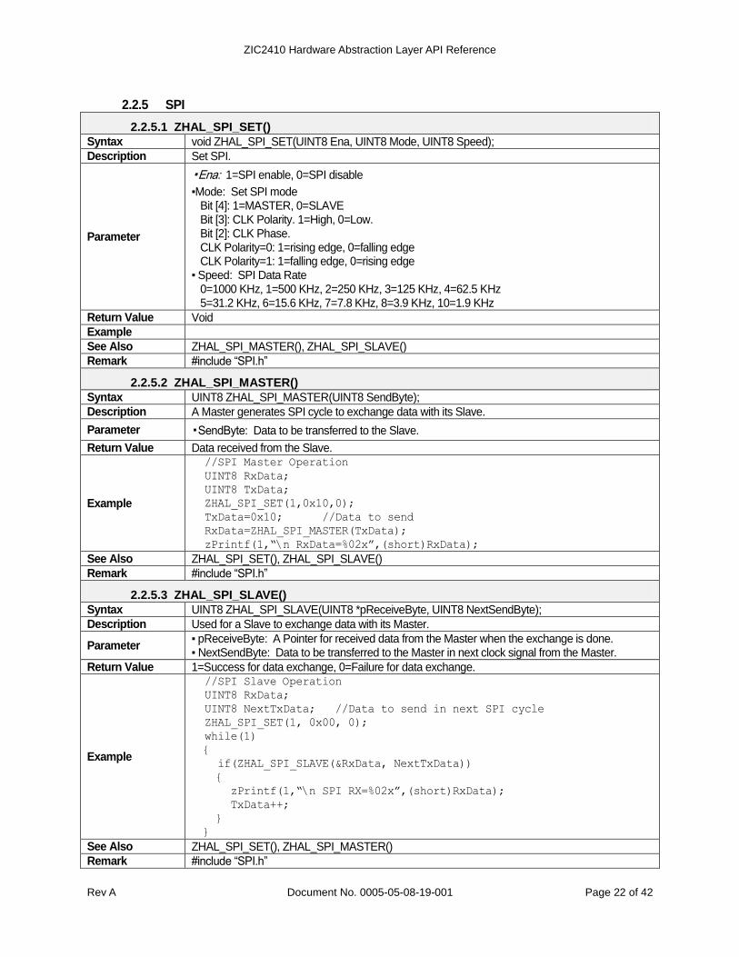
2.2.5 SPI
2.2.5.1 ZHAL_SPI_SET()
Syntax void ZHAL_SPI_SET(UINT8 Ena, UINT8 Mode, UINT8 Speed);
Description Set SPI.
Parameter
▪Ena: 1=SPI enable, 0=SPI disable
▪Mode: Set SPI mode Bit [4]: 1=MASTER, 0=SLAVE Bit [3]: CLK Polarity. 1=High, 0=Low. Bit [2]: CLK Phase. CLK Polarity=0: 1=rising edge, 0=falling edge CLK Polarity=1: 1=falling edge, 0=rising edge
▪ Speed: SPI Data Rate 0=1000 KHz, 1=500 KHz, 2=250 KHz, 3=125 KHz, 4=62.5 KHz 5=31.2 KHz, 6=15.6 KHz, 7=7.8 KHz, 8=3.9 KHz, 10=1.9 KHz
Return Value Void
Example
See Also ZHAL_SPI_MASTER(), ZHAL_SPI_SLAVE()
Remark #include “SPI.h”
2.2.5.2 ZHAL_SPI_MASTER()
Syntax UINT8 ZHAL_SPI_MASTER(UINT8 SendByte);
Description A Master generates SPI cycle to exchange data with its Slave.
Parameter ▪SendByte: Data to be transferred to the Slave.
Return Value Data received from the Slave.
Example
//SPI Master Operation
UINT8 RxData;
UINT8 TxData;
ZHAL_SPI_SET(1,0x10,0);
TxData=0x10; //Data to send
RxData=ZHAL_SPI_MASTER(TxData);
zPrintf(1,“\n RxData=%02x”,(short)RxData);
See Also ZHAL_SPI_SET(), ZHAL_SPI_SLAVE()
Remark #include “SPI.h”
2.2.5.3 ZHAL_SPI_SLAVE()
Syntax UINT8 ZHAL_SPI_SLAVE(UINT8 *pReceiveByte, UINT8 NextSendByte);
Description Used for a Slave to exchange data with its Master.
Parameter ▪ pReceiveByte: A Pointer for received data from the Master when the exchange is done. ▪ NextSendByte: Data to be transferred to the Master in next clock signal from the Master.
Return Value 1=Success for data exchange, 0=Failure for data exchange.
Example
//SPI Slave Operation
UINT8 RxData;
UINT8 NextTxData; //Data to send in next SPI cycle
ZHAL_SPI_SET(1, 0x00, 0);
while(1)
{
if(ZHAL_SPI_SLAVE(&RxData, NextTxData))
{
zPrintf(1,“\n SPI RX=%02x”,(short)RxData);
TxData++;
}
}
See Also ZHAL_SPI_SET(), ZHAL_SPI_MASTER()
Remark #include “SPI.h”

ZIC2410 Hardware Abstraction Layer API Reference
Rev A Document No. 0005-05-08-19-001 Page 23 of 42
2.2.6 WDT
2.2.6.1 ZHAL_WDT_SET()
Syntax void ZHAL_WDT_SET(UINT8 Ena, UINT8 Timeout);
Description Sets the Watchdog Timer (WDT). The Boot-up sequence requires time, so it is recommended that the WDT is initially disabled and enabled after completion of the boot-up sequence.
Parameter ▪ Ena: 1=WDT enable, 0=WDT disable
▪ Timeout: The period until the WDT counter is 0 and the system is reset 0=62.5ms, 1=125ms, 2=250ms, 3=500ms
Return Value Void
Example
See Also ZHAL_WDT_RESTART()
Remark #include “WDT.h”
2.2.6.2 ZHAL_WDT_RESTART()
Syntax void ZHAL_WDT_RESTART();
Description Initializes the WDT counter
Parameter
Return Value Void
Example
See Also ZHAL_WDT_SET()
Remark #include “WDT.h”
2.2.6.3 ZSYS_WDT_SET()
Syntax void ZSYS_WDT_SET(UINT16 Timer0Period_Cnt);
Description Sets the WDT period by Timer0. Resets the system if ZSYS_WDT_SET() function is not called within the defined time.
Parameter ▪ Timer0Period_Cnt: Interrupt period by using tick count of Timer0 interrupt.
Return Value Void
Example ZHAL_TIMER0_SET(1,0,1,1); //Set Timer0 per 1ms
ZSYS_WDT_SET(10000); //Set WDT reset period per 10 sec.
See Also ZHAL_WDT_SET(), ZHAL_WDT_RESTART()
Remark #include “WDT.h”
2.2.7 POWER CONTROL
2.2.7.1 ZHAL_PWRMNGT_SET()
Syntax void ZHAL_PWRMNGT_SET(UINT8 RF_PowerOff);
Description Reduce current consumption when it is needed by cutting power on RF block.
Parameter ▪ PowerOff: 1=Cut power, 0=Supply power.
Return Value Void
Example
See Also ZHAL_IDLE_MODE()
Remark #include “POWER.h”
2.2.7.2 ZHAL_IDLE_MODE()
Syntax void ZHAL_IDLE_MODE();
Description Current consumption is reduced by entering the IDLE mode. This function calls ZHAL_PWRMNGT_SET(). When UART/RF/VOICE/RTC interrupt occurs, a system is woken.
Parameter
Return Value Void
Example ZHAL_IDLE_MODE(); //Enter Idle mode
See Also ZHAL_PWRMNGT_SET(), ZHAL_PD_SET()
ZIC2410 Hardware Abstraction Layer API Reference
Rev A Document No. 0005-05-08-19-001 Page 24 of 42
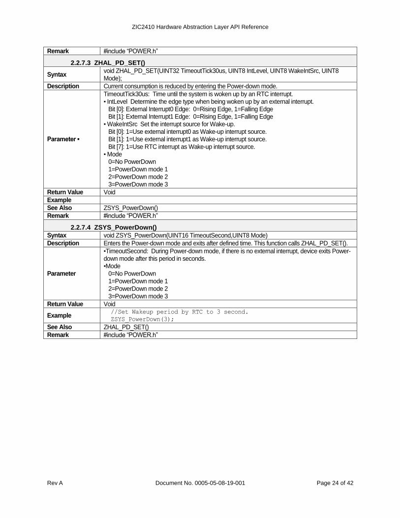
Remark #include “POWER.h”
2.2.7.3 ZHAL_PD_SET()
Syntax void ZHAL_PD_SET(UINT32 TimeoutTick30us, UINT8 IntLevel, UINT8 WakeIntSrc, UINT8 Mode);
Description Current consumption is reduced by entering the Power-down mode.
Parameter ▪
TimeoutTick30us: Time until the system is woken up by an RTC interrupt. ▪ IntLevel Determine the edge type when being woken up by an external interrupt.
Bit [0]: External Interrupt0 Edge: 0=Rising Edge, 1=Falling Edge Bit [1]: External Interrupt1 Edge: 0=Rising Edge, 1=Falling Edge
▪ WakeIntSrc Set the interrupt source for Wake-up. Bit [0]: 1=Use external interrupt0 as Wake-up interrupt source. Bit [1]: 1=Use external interrupt1 as Wake-up interrupt source. Bit [7]: 1=Use RTC interrupt as Wake-up interrupt source.
▪ Mode 0=No PowerDown 1=PowerDown mode 1 2=PowerDown mode 2 3=PowerDown mode 3
Return Value Void
Example
See Also ZSYS_PowerDown()
Remark #include “POWER.h”
2.2.7.4 ZSYS_PowerDown()
Syntax void ZSYS_PowerDown(UINT16 TimeoutSecond,UINT8 Mode)
Description Enters the Power-down mode and exits after defined time. This function calls ZHAL_PD_SET().
Parameter
▪TimeoutSecond: During Power-down mode, if there is no external interrupt, device exits Power-down mode after this period in seconds. ▪Mode
0=No PowerDown 1=PowerDown mode 1 2=PowerDown mode 2 3=PowerDown mode 3
Return Value Void
Example //Set Wakeup period by RTC to 3 second.
ZSYS_PowerDown(3);
See Also ZHAL_PD_SET()
Remark #include “POWER.h”

ZIC2410 Hardware Abstraction Layer API Reference
Rev A Document No. 0005-05-08-19-001 Page 25 of 42
2.2.8 SECURITY
2.2.8.1 ZHAL_SEC_KEY_SET()
Syntax void ZHAL_SEC_KEY_SET(UINT8 KeyNum, UINT8 *pKey);
Description Sets the key used for security.
Parameter ▪ KeyNum: Selects desired key. 1=KEY1, 0=KEY0
▪ pKey: A pointer for 16 byte buffer which includes desired key value. Return Value Void
Example
UINT8 KEY0[16];
UINT8 KEY1[16];
//Set KEY0 for 0F 0E … 00
KEY0[0]=0x00;
...
KEY0[15]=0x0F;
ZHAL_SEC_KEY_SET(0, &KEY0[0]);
//Set KEY1 for 1F 1E … 10
KEY1[0]=0x10;
...
KEY1[15]=0x1F
ZHAL_SEC_KEY_SET(1, &KEY1[0]);
See Also ZHAL_SEC_KEY_CHOICE()
Remark #include “SECURITY.h”
2.2.8.2 ZHAL_SEC_TXNONCE_KEY_SEQ_SET()
Syntax void ZHAL_SEC_TXNONCE_KEY_SEQ_SET(UINT8 KeySeq);
Description Sets the Key Sequence Number of TX NONCE from the materials used in security.
Parameter ▪ KeySeq: Key Sequence Number to be set.
Return Value Void
Example
UINT8 ReadKeySeq;
//Set Key Sequence Number to 0x01.
ZHAL_SEC_TXNONCE_KEY_SEQ_SET(0x01);
//Read Key Sequence Number GetKeySeq=ZHAL_SEC_TXNONCE_KEY_SEQ_GET();
See Also ZHAL_SEC_TXNONCE_KEY_SEQ_GET(), ZHAL_SEC_TXNONCE_FRAME_CNT_SET(), ZHAL_SEC_TXNONCE_EXT_ADDR_SET()
Remark #include “SECURITY.h”
2.2.8.3 ZHAL_SEC_RXNONCE_KEY_SEQ_SET()
Syntax void ZHAL_SEC_RXNONCE_KEY_SEQ_SET(UINT8 KeySeq);
Description Sets the Key Sequence Number of RX NONCE from the materials used in security.
Parameter ▪ KeySeq: Key Sequence Number to be set.
Return Value Void
Example
UINT8 ReadKeySeq;
//Sets the Key Sequence Number to 0x01.
ZHAL_SEC_RXNONCE_KEY_SEQ_SET(0x01);
//Reads the Key Sequence Number
GetKeySeq=ZHAL_SEC_RXNONCE_KEY_SEQ_GET()
See Also ZHAL_SEC_RXNONCE_KEY_SEQ_GET(), ZHAL_SEC_RXNONCE_FRAME_CNT_SET(), ZHAL_SEC_RXNONCE_EXT_ADDR_SET()

ZIC2410 Hardware Abstraction Layer API Reference
Rev A Document No. 0005-05-08-19-001 Page 26 of 42
Remark #include “SECURITY.h”
2.2.8.4 ZHAL_SEC_TXNONCE_KEY_SEQ_GET()
Syntax UINT8 ZHAL_SEC_TXNONCE_KEY_SEQ_GET();
Description Gets the Key Sequence Number of TX NONCE from the materials used in security.
Parameter Void
Return Value Key Sequence Number to be read.
Example
UINT8 ReadKeySeq;
//Set Key Sequence Number to 0x01.
ZHAL_SEC_TXNONCE_KEY_SEQ_SET(0x01);
//Read Key Sequence Number
GetKeySeq=ZHAL_SEC_TXNONCE_KEY_SEQ_GET();
See Also ZHAL_SEC_TXNONCE_KEY_SEQ_GET()
Remark #include “SECURITY.h”
2.2.8.5 ZHAL_SEC_RXNONCE_KEY_SEQ_GET()
Syntax UINT8 ZHAL_SEC_RXNONCE_KEY_SEQ_GET();
Description Gets the Key Sequence Number of RX NONCE from the materials used in security.
Parameter Void
Return Value Key Sequence Number to be read.
Example
UINT8 ReadKeySeq;
//Set Key Sequence Number to 0x01.
ZHAL_SEC_RXNONCE_KEY_SEQ_SET(0x01);
//Read Key Sequence Number
GetKeySeq=ZHAL_SEC_RXNONCE_KEY_SEQ_GET()
See Also ZHAL_SEC_RXNONCE_KEY_SEQ_GET()
Remark #include “SECURITY.h”
2.2.8.6 ZHAL_SEC_TXNONCE_FRAME_CNT_SET()
Syntax void ZHAL_SEC_TXNONCE_FRAME_CNT_SET(UINT32 FrameCnt);
Description Sets the Frame Counter of TX NONCE from the materials used in security.
Parameter ▪ FrameCnt: Frame Counter to be set.
Return Value Void
Example
UINT32 ReadFrameCnt;
//Set Frame Counter to 0x01020304
ZHAL_SEC_TXNONCE_FRAME_CNT_SET(0x01020304);
//Read Frame Counter
ReadFrameCnt=ZHAL_SEC_TXNONCE_FRAME_CNT_GET()
See Also ZHAL_SEC_TXNONCE_FRAME_CNT_GET(), ZHAL_SEC_TXNONCE_KEY_SEQ_SET(), ZHAL_SEC_TXNONCE_EXT_ADDR_SET()
Remark #include “SECURITY.h”
2.2.8.7 ZHAL_SEC_RXNONCE_FRAME_CNT_SET()
Syntax void ZHAL_SEC_RXNONCE_FRAME_CNT_SET(UINT32 FrameCnt);
Description Gets the Frame Counter of RX NONCE from the materials used in security.
Parameter ▪ FrameCnt: Frame Counter to be set.
Return Value Void

ZIC2410 Hardware Abstraction Layer API Reference
Rev A Document No. 0005-05-08-19-001 Page 27 of 42
Example
UINT32 ReadFrameCnt;
//Set Frame Counter to 0x01020304.
ZHAL_SEC_RXNONCE_FRAME_CNT_SET(0x01020304);
//Read Frame Counter.
ReadFrameCnt=ZHAL_SEC_RXNONCE_FRAME_CNT_GET()
See Also ZHAL_SEC_RXNONCE_FRAME_CNT_GET(), ZHAL_SEC_RXNONCE_KEY_SEQ_SET(), ZHAL_SEC_RXNONCE_EXT_ADDR_SET()
Remark #include “SECURITY.h”
2.2.8.8 ZHAL_SEC_TXNONCE_FRAME_CNT_GET()
Syntax UINT32 ZHAL_SEC_TXNONCE_FRAME_CNT_GET();
Description Reads the Frame Counter of TX NONCE from the materials used in security.
Parameter Void
Return Value Frame Counter to be read.
Example
UINT32 ReadFrameCnt;
//Set Frame Counter to 0x01020304.
ZHAL_SEC_TXNONCE_FRAME_CNT_SET(0x01020304);
//Read Frame Counter
ReadFrameCnt=ZHAL_SEC_TXNONCE_FRAME_CNT_GET()
See Also ZHAL_SEC_TXNONCE_FRAME_CNT_SET()
Remark #include “SECURITY.h”
2.2.8.9 ZHAL_SEC_RXNONCE_FRAME_CNT_GET()
Syntax UINT32 ZHAL_SEC_RXNONCE_FRAME_CNT_GET();
Description Reads the Frame Counter of RX NONCE from the materials used in security.
Parameter Void
Return Value Frame Counter to be read.
Example
UINT32 ReadFrameCnt;
//Set Frame Counter to 0x01020304.
ZHAL_SEC_RXNONCE_FRAME_CNT_SET(0x01020304);
//Read Frame Counter.
ReadFrameCnt=ZHAL_SEC_RXNONCE_FRAME_CNT_GET()
See Also ZHAL_SEC_RXNONCE_FRAME_CNT_SET()
Remark #include “SECURITY.h”
2.2.8.10 ZHAL_SEC_TXNONCE_EXT_ADDR_SET()
Syntax void ZHAL_SEC_TXNONCE_EXT_ADDR_SET(UINT8 *pIEEE);
Description Sets Extend Address of TX NONCE from the materials used in security.
Parameter ▪ pIEEE: The pointer of Extend Address to be set.
Return Value Void
Example
UINT8 ExtAddr[8];
//Set Frame Counter to 0x0102…0708.
ExtAddr[0]=0x01; ExtAddr[4]=0x05;
ExtAddr[1]=0x02; ExtAddr[5]=0x06;
ExtAddr[2]=0x03; ExtAddr[6]=0x07;
ExtAddr[3]=0x04; ExtAddr[7]=0x08
ZHAL_SEC_TXNONCE_EXT_ADDR_SET(ExtAddr);
See Also ZHAL_SEC_TXNONCE_KEY_SEQ_SET(), ZHAL_SEC_TXNONCE_FRAME_CNT_SET()
ZIC2410 Hardware Abstraction Layer API Reference
Rev A Document No. 0005-05-08-19-001 Page 28 of 42
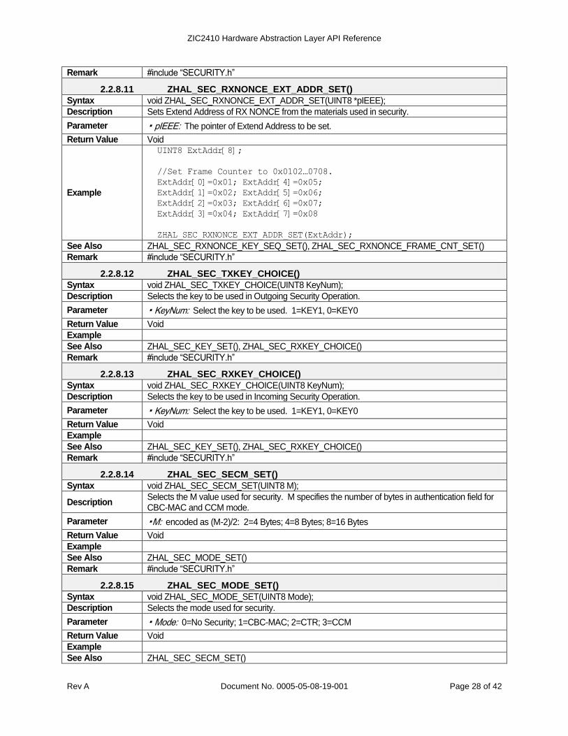
Remark #include “SECURITY.h”
2.2.8.11 ZHAL_SEC_RXNONCE_EXT_ADDR_SET()
Syntax void ZHAL_SEC_RXNONCE_EXT_ADDR_SET(UINT8 *pIEEE);
Description Sets Extend Address of RX NONCE from the materials used in security.
Parameter ▪ pIEEE: The pointer of Extend Address to be set.
Return Value Void
Example
UINT8 ExtAddr[8];
//Set Frame Counter to 0x0102…0708.
ExtAddr[0]=0x01; ExtAddr[4]=0x05;
ExtAddr[1]=0x02; ExtAddr[5]=0x06;
ExtAddr[2]=0x03; ExtAddr[6]=0x07;
ExtAddr[3]=0x04; ExtAddr[7]=0x08
ZHAL_SEC_RXNONCE_EXT_ADDR_SET(ExtAddr);
See Also ZHAL_SEC_RXNONCE_KEY_SEQ_SET(), ZHAL_SEC_RXNONCE_FRAME_CNT_SET()
Remark #include “SECURITY.h”
2.2.8.12 ZHAL_SEC_TXKEY_CHOICE()
Syntax void ZHAL_SEC_TXKEY_CHOICE(UINT8 KeyNum);
Description Selects the key to be used in Outgoing Security Operation.
Parameter ▪ KeyNum: Select the key to be used. 1=KEY1, 0=KEY0
Return Value Void
Example
See Also ZHAL_SEC_KEY_SET(), ZHAL_SEC_RXKEY_CHOICE()
Remark #include “SECURITY.h”
2.2.8.13 ZHAL_SEC_RXKEY_CHOICE()
Syntax void ZHAL_SEC_RXKEY_CHOICE(UINT8 KeyNum);
Description Selects the key to be used in Incoming Security Operation.
Parameter ▪ KeyNum: Select the key to be used. 1=KEY1, 0=KEY0
Return Value Void
Example
See Also ZHAL_SEC_KEY_SET(), ZHAL_SEC_RXKEY_CHOICE()
Remark #include “SECURITY.h”
2.2.8.14 ZHAL_SEC_SECM_SET()
Syntax void ZHAL_SEC_SECM_SET(UINT8 M);
Description Selects the M value used for security. M specifies the number of bytes in authentication field for CBC-MAC and CCM mode.
Parameter ▪M: encoded as (M-2)/2: 2=4 Bytes; 4=8 Bytes; 8=16 Bytes
Return Value Void
Example
See Also ZHAL_SEC_MODE_SET()
Remark #include “SECURITY.h”
2.2.8.15 ZHAL_SEC_MODE_SET()
Syntax void ZHAL_SEC_MODE_SET(UINT8 Mode);
Description Selects the mode used for security.
Parameter ▪ Mode: 0=No Security; 1=CBC-MAC; 2=CTR; 3=CCM
Return Value Void
Example
See Also ZHAL_SEC_SECM_SET()

ZIC2410 Hardware Abstraction Layer API Reference
Rev A Document No. 0005-05-08-19-001 Page 29 of 42
Remark #include “SECURITY.h”
2.2.8.16 ZHAL_SEC_TXL_SET()
Syntax void ZHAL_SEC_TXL_SET(UINT8 L);
Description Selects the L value used in encryption. L value has a different meaning for different encryption modes.
Parameter
▪L
CTR: The number of byte existing between the first byte encrypted and the field which represents the length of packet. CBC-MAC: The number of byte existing between the first byte which processes authentication and the field which represents the length of packet. CCM: The number of byte which is included in authentication, but is not included in encryption.
Return Value Void
Example
See Also ZHAL_SEC_RXL_SET()
Remark #include “SECURITY.h”
2.2.8.17 ZHAL_SEC_RXL_SET()
Syntax void ZHAL_SEC_RXL_SET(UINT8 L);
Description Select L value used in decryption. L value has a different meaning for different decryption modes.
Parameter
▪L
CTR: The number of byte existing between the first byte decrypted and the field which represents the length of packet. CBC-MAC: The number of byte existing between the first byte which processes authentication and the field which represents the length of packet. CCM: The number of byte which is included in authentication, but is not included in encryption.
Return Value Void
Example
See Also ZHAL_SEC_TXL_SET()
Remark #include “SECURITY.h”
2.2.8.18 ZHAL_SEC_SAES()
Syntax void ZHAL_SEC_SAES (UINT8 KeyNum, UINT8 *pPlainText, UINT8 *pCipherText);
Description Perform Stand Alone AES operation for PlainText.
Parameter ▪ KeyNum: Select the Key to be used. 1=KEY1, 0=KEY0
▪ pPlainText: A pointer for 16 byte buffer which includes an unencoded message to be encrypted. ▪ pCipherText: A pointer for 16 byte buffer which includes a coded message.
Return Value Void
Example
UINT8 PlainText[16];
UINT8 CipherText[16];
PlainText[0]=0x00;
...
PlainText[15]=0x0F;
//AES operation by KEY0.
ZHAL_SEC_SAES(0,&PlainText[0],&CipherText[0]);
See Also
Remark #include “SECURITY.h”
2.2.8.19 ZHAL_SEC_ENCRYPTION()
Syntax UINT8 ZHAL_SEC_ENCRYPTION (UINT8 *pText, UINT8 Len, UINT32 FCnt, UINT8 KSeq);
Description Processes encryption by adjusting CTR mode for the defined buffer and returns the result. Before calling this function, TxKey and TxNonceExtAddr should be set.

ZIC2410 Hardware Abstraction Layer API Reference
Rev A Document No. 0005-05-08-19-001 Page 30 of 42
Parameter
▪ pText: The pointer for the PlainText buffer, which is encrypted. When the function is returned, it
means the pointer for the CipherText buffer, which is the result of CipherText buffer. ▪ Len: The length(Byte) of PlainText ▪ FCnt: FrameCounter used in encryption. FCnt used in encryption and FCnt used in decryption should be same. ▪ KSeq: KeySequenceNumber used in encryption. KSeq used in encryption and KSeq used in decryption should be same.
Return Value 0=success, 2=fail because of length excess.
Example
UINT8 Text[16];
UINT8 Key[16];
UINT32 FCnt;
UINT8 KSeq;
UINT8 ExtAddr[8];
//Set Text to decrypt
Text[0]=0x10;
...
Text[15]=0x1F;
//Set TxKey Buffer
Key[0]=0x00;
...
Key[15]=0x0F;
//Set TxNonceExtAddr
ExtAddr[0]=0x20;
...
ExtAddr[7]=0x27;
//If AES Clock is disabled, enable the clock first !!
ZHAL_CLOCK_BLOCK_SET(0,1);
ZHAL_SEC_KEY_SET(0, Key); //Set KEY0
ZHAL_SEC_TXKEY_CHOICE(0); //Select KEY0 as TxKey
ZHAL_SEC_TXNONCE_EXT_ADDR_SET(&ExtAddr[0]);//Set TxExtAddr
ZHAL_SEC_RXKEY_CHOICE(0); //Select KEY0 as RxKey
ZHAL_SEC_RXNONCE_EXT_ADDR_SET(&ExtAddr[0]);//Set RxExtAddr
//Disable AES clock to minimize current consumption
ZHAL_CLOCK_BLOCK_SET(0,0);
//FrameCount and KeySeqNumber for Encryption
FCnt=0x11223344;
KSeq=0x55;
//Encryption Operation
ZHAL_SEC_ENCRYPTION(&Text[0],16,FCnt, KSeq);
//Returned Text[ ] is encrypted data.
//Decryption Operation
ZHAL_SEC_DECRYPTION(&Text[0],16,FCnt, KSeq);
//Returned Text[ ] should be original Text[ ]
//Text[0]=0x10,Text[1]=0x11,...,Text[15]=0x1F

ZIC2410 Hardware Abstraction Layer API Reference
Rev A Document No. 0005-05-08-19-001 Page 31 of 42
See Also ZHAL_SEC_KEY_SET(), ZHAL_SEC_TXNONCE_EXT_ADDR_SET(), ZHAL_SEC_TXKEY_CHOICE(), ZHAL_SEC_DECRYPTION()
Remark #include “SECURITY.h”
2.2.8.20 ZHAL_SEC_DECRYPTION()
Syntax UINT8 ZHAL_SEC_DECRYPTION (UINT8 *pText, UINT8 Len, UINT32 FCnt, UINT8 KSeq);
Description Processes decryption by adjusting CTR mode for the defined buffer and returns the result. Before calling this function, RxKey and RxNonceExtAddr should be set.
Parameter
▪ pText: When this function is called, it means the pointer for CipherText buffer, which is
decrypted. When the function is returned, it means the pointer for PlainText buffer. ▪ Len: The length(Byte) of CipherText. ▪ FCnt: FrameCounter used in decryption. FCnt used in encryption and FCnt used in decryption should be same. ▪ KSeq: It means KeySequenceNumber used in encryption. KSeq used in encryption and KSeq used in decryption should be same.
Return Value 0=success, 2=fail because of length excess.

ZIC2410 Hardware Abstraction Layer API Reference
Rev A Document No. 0005-05-08-19-001 Page 32 of 42
Example
UINT8 Text[16];
UINT8 Key[16];
UINT32 FCnt;
UINT8 KSeq;
UINT8 ExtAddr[8];
//Set Text to decrypt
Text[0]=0x10;
...
Text[15]=0x1F;
//Set TxKey Buffer
Key[0]=0x00;
...
Key[15]=0x0F;
//Set TxNonceExtAddr
ExtAddr[0]=0x20;
...
ExtAddr[7]=0x27;
//If AES Clock is disabled, enable the clock first !!
ZHAL_CLOCK_BLOCK_SET(0, 1);
ZHAL_SEC_KEY_SET(0, Key); //Set KEY0
ZHAL_SEC_TXKEY_CHOICE(0); //Select KEY0 as TxKey
ZHAL_SEC_TXNONCE_EXT_ADDR_SET(&ExtAddr[0]);//Set TxExtAddr
ZHAL_SEC_RXKEY_CHOICE(0); //Select KEY0 as RxKey
ZHAL_SEC_RXNONCE_EXT_ADDR_SET(&ExtAddr[0]);//Set RxExtAddr
//Disable AES clock to minimize current consumption
ZHAL_CLOCK_BLOCK_SET(0,0);
//FrameCount and KeySeqNumber for Encryption
FCnt=0x11223344;
KSeq=0x55;
//Encryption Operation
ZHAL_SEC_ENCRYPTION(&Text[0],16,FCnt, KSeq);
//Returned Text[ ] is encrypted data.
//Decryption Operation
ZHAL_SEC_DECRYPTION(&Text[0],16,FCnt, KSeq);
//Returned Text[ ] should be original Text[ ]
//Text[0]=0x10,Text[1]=0x11,...,Text[15]=0x1F
See Also ZHAL_SEC_KEY_SET(), ZHAL_SEC_RXNONCE_EXT_ADDR_SET(), ZHAL_SEC_RXKEY_CHOICE(), ZHAL_SEC_ENCRYPTION()
Remark #include “SECURITY.h”
2.2.9 FLASH
2.2.9.1 ZHAL_FLASH_PAGE_ERASE()
Syntax void ZHAL_FLASH_PAGE_ERASE(UINT16 FlashWordAddr);

ZIC2410 Hardware Abstraction Layer API Reference
Rev A Document No. 0005-05-08-19-001 Page 33 of 42
Description Erases the Flash area per page(512 byte)
Parameter ▪ FlashWordAddr: The start address of flash page to be erased in linear word address unit. One word consists of 4 bytes.
Return Value Void
Example
See Also Z HAL_FLASH_PAGE_WRITE()
Remark #include “FLASH.h”
2.2.9.2 ZHAL_FLASH_PAGE_WRITE()
Syntax void ZHAL_FLASH_PAGE_WRITE(UINT16 CodeAddr, UINT8 *pByteBuf);
Description Writes the Flash area per page(512 byte). This function calls ZHAL_FLASH_PAGE_ERASE() to erase flash. After erasing, the flash area can be written.
Parameter ▪ CodeAddr: The start address of code area to be written. ▪ pByteBuf: A pointer for 512 byte buffer which include data to be written.
Return Value Void
Example
UINT8 code UserFlash[512] _at_ 0x1000;
UINT8 FlashWrite[512];
//Copy FlashWrite buffer to UserFlash area
FlashWrite[0]=0x00;
...
FlashWrite[511]=0xFF;
ZHAL_FLASH_PAGE_WRITE(0x1000, &FlashWrite[0]);
See Also ZHAL_FLASH_PAGE_ERASE()
Remark #include “FLASH.h”
2.2.10 ADC
2.2.10.1 ZHAL_ADC_SET()
Syntax void ZHAL_ADC_SET(UINT8 Ena, UINT8 Ref, UINT8 AdcChan);
Description Sets the desired ADC channel.
Parameter
▪ Ena: 1=ADC enable, 0=ADC disable
▪ Ref: Select the reference voltage for ADC measurement. 0=Internal Reference. TOP=1.2V, BOT=0.3V,VMID=0.75V 1=Reserved 2=External Reference. TOP=ACH2, BOT=ACH3, VMID=(ACH2+ACH3)/2 3=External Reference. TOP=VDD, BOT=GND, VMID=(VDD+GND)/2
▪ AdcChan :Select desired ADC channel. 0=ACH0 1=ACH1 2=ACH2 3=ACH3 4=Difference between ACH0 and ACH1. 5=Difference between ACH2 and ACH3. 6=Internal temperature sensor 7=Battery monitoring
Return Value Void
Example
See Also ZHAL_ADC_GET(), ZSYS_ADC_GET()
Remark #include “ADC.h”
2.2.10.2 ZHAL_ADC_GET()
Syntax UINT16 ZHAL_ADC_GET();
Description Gets the ADC value for the ADC channel set by ZHAL_ADC_SET() function.

ZIC2410 Hardware Abstraction Layer API Reference
Rev A Document No. 0005-05-08-19-001 Page 34 of 42
Parameter
Return Value The ADC value from the defined ADC channel
Example
See Also ZHAL_ADC_SET(), ZSYS_ADC_GET()
Remark #include “ADC.h”
2.2.10.3 ZSYS_ADC_GET()
Syntax UINT16 ZSYS_ADC_GET(UINT8 AdcChan);
Description Sets the ADC channel and gets the ADC value for that corresponding channel. This function calls ZHAL_ADC_SET() and ZHAL_ADC_GET().
Parameter
▪ AdcChan: Desired ADC channel.
0=ACH0 1=ACH1 2=ACH2 3=ACH3 4=Difference between ACH0 and ACH1. 5=Difference between ACH2 and ACH3. 6=Internal temperature sensor. 7=Battery monitoring.
Return Value ADC value for defined ADC channel.
Example
UINT16 ADC0_Read;
UINT16 ADC1_Read;
//Read ADC channel 0/1
ADC0_Read=ZSYS_ADC_GET(0);
ADC1_Read=ZSYS_ADC_GET(1);
zPrintf(1,“\n READ: ADC0=%04x,ADC1=%04x”,ADC0_Read,ADC1_Read);
See Also ZHAL_ADC_SET(), ZHAL_ADC_GET()
Remark #include “ADC.h”
2.2.11 KEYSCAN
2.2.11.1 ZHAL_KEYSCAN_SET()
Syntax void ZHAL_KEYSCAN_SET(UINT8 ScanEN,UINT8 P0andEN, UINT8 P0mask);
Description Select a P0 as input
Parameter
▪ ScanEN: This value controls to wake up MCU by an external interrupt in power-down mode.
0=MCU wakes up when INT0 or INT1 signal is going to HIGH ( This is normal case in MCU.) 1=MCU is woken up by wakeup signal of RTC.
Remote control function can be implemented by the interrupt service routine of MCU when WAKEUP signal occurs by adjusting RTDLY value in RTC while INT0 or INT1 is LOW. ▪ P0andEN
1=P0 and P0MSK are OR'ed per bit. The bits of the result value are to be AND'ed and then output to P1.7. This function is used to implement remote control function.
▪ P0mask: This value is used for masking the input of P0 pin. 1=the selected bit is ignored.
Return Value Void
Example
See Also
Remark #include “KEYSCAN.h”

ZIC2410 Hardware Abstraction Layer API Reference
Rev A Document No. 0005-05-08-19-001 Page 35 of 42
2.2.12 LCD
2.2.12.1 ZHAL_LCD_BUSY()
Syntax void ZHAL_LCD_Busy();
Description LCD Status Check Function
Parameter
Return Value 1=LCD is in busy status or does not exist. 2=LCD is in idle status.
Example
See Also
Remark #include “LCD.c”
2.2.12.2 ZHAL_LCD_WR_CTRL_REG()
Syntax void ZHAL_LCD_WR_CTRL_REG(UINT8 ctrl);
Description Writes the CTRL register. The selection of these registers depends on the combination of R/W and RS signals. RS=L, R/W=L � instruction write
Parameter ▪ ctrl Input register value
Return Value Void
Example
UINT8 x,y;
x=col&0x3F|COLUMN; //col.and.0x3f.or.setx
y=row&0x07|PAGE; //row.and.0x07.or.sety
Wr_Ctrl (x);
Wr_Ctrl (y);
See Also
Remark #include “LCD.h”
2.2.12.3 ZHAL_LCD_RD_CTRL_REG()
Syntax UINT8 ZHAL_LCD_RD_CTRL_REG();
Description
Reads status
RS = L, R/W = H → LCD Status Read
RS R/W DB7 DB6 DB5 DB4 DB3 DB2 DB1 DB0
0 1 busy 0 ON/OFF RESET 0 0 0 0
▪ Busy
1=the ZIC2410 is executing an internal operation. No instructions are being accepted. 0=the ZIC2410 is ready to accept new instructions.
▪ ON/OFF
1=the display is OFF. 0=the display is ON.
▪ RESET
1=the system is being initialized. No instructions are accepted except reading status. 0=initialization is complete and the system is in a normal operating condition.
Parameter Void
Return Value Status data to be read
Example
See Also
Remark #include “LCD.h”
2.2.12.4 ZHAL_LCD_WR_DATA_REG()
Syntax void ZHAL_LCD_WR_DATA_REG(UINT8 dat);
Description Writes the data(D0 ~ D7) into the display data RAM. After writing instruction, Y address is increased by 1 automatically. RS=H, R/W=L � LCD Display Data write
Parameter ▪ dat data to be written on LCD

ZIC2410 Hardware Abstraction Layer API Reference
Rev A Document No. 0005-05-08-19-001 Page 36 of 42
Return Value Void
Example
See Also
Remark #include “LCD.h”
2.2.12.5 ZHAL_LCD_RD_DATA_REG()
Syntax UINT8 ZHAL_LCD_RD_DATA_REG();
Description
Reads the data(D0 ~ D7)from the display data RAM After reading instruction, Y address is increased by 1 automatically. One time of dummy read must be required after column address setting. RS=H, R/W=H � LCD Display Data Read
Parameter
Return Value LCD display data
Example
See Also
Remark #include “LCD.h”
2.2.12.6 ZHAL_LCD_CS_LCM_L()
Syntax void ZHAL_LCD_CS_LCM_L();
Description Chip select function of LCD module
Parameter Void
Return Value Void
Example
See Also
Remark #include “LCD.h”
2.2.12.7 ZHAL_LCD_CS_LCM_M()
Syntax void ZHAL_LCD_CS_LCM_M();
Description Chip select function of LCD module
Parameter Void
Return Value Void
Example
See Also
Remark #include “LCD.h”
2.2.12.8 ZHAL_LCD_ADDR_XY()
Syntax void ZHAL_LCD_ADDR_XY();
Description Sets the LCD address
Parameter Void
Return Value Void
Example
See Also
Remark #include “LCD.h”
2.2.12.9 ZHAL_LCD_WR_DATA()
Syntax void ZHAL_LCD_WR_DATA(UINT8 x);
Description Writes data (D0~D7) into the display data RAM After writing instruction, Y address is increased by 1 automatically.
Parameter ▪ x: data to be written on LCD.
Return Value Void

ZIC2410 Hardware Abstraction Layer API Reference
Rev A Document No. 0005-05-08-19-001 Page 37 of 42
Example
dat=0xff;
for(i=0;i<2;i++)
{
for(row=0;row<8;row++)
for(col=0;col<LCMLIMIT;col++)
{
ZHAL_LCD_WR_DATA(dat);
dat=~dat;
}
Delay(1000);
dat=~dat;
}
See Also
Remark #include “LCD.h”
2.2.12.10 ZHAL_LCD_CLR_RAM()
Syntax ZHAL_LCD_CLR_RAM();
Description Clears the LCD display.
Parameter Void
Return Value Void
Example
See Also
Remark #include “LCD.h”
2.2.12.11 ZHAL_LCD_DIS_ONE_WORD()
Syntax void ZHAL_LCD_DIS_ONE_WORD(UINT8 x, UINT8 y, UINT8 *Lib, UINT8 order, UINT8 widthw);
Description Displays a word
Parameter
▪ x - LCD column address
▪ y - LCD row address
▪ *Lib - Pointer to LCD Display data
▪ order - LCD Display Number
▪ widthw - The size of display word
Return Value Void
Example
See Also
Remark #include “LCD.h”
2.2.12.12 ZHAL_LCD_DIS_STRING()
Syntax void ZHAL_LCD_DIS_STRING(UINT8 x, UINT8 y, UINT8 *str, UINT8 i, UINT8 ch8_16);
Description Displays a string
Parameter
▪ x - LCD column address
▪ y - LCD row address
▪ *str - Pointer to LCD Display data
▪ I - LCD Display char Number ▪ ch8_16 -The size of character
0=display character 8 byte 1=display character 16 byte
Return Value Void

ZIC2410 Hardware Abstraction Layer API Reference
Rev A Document No. 0005-05-08-19-001 Page 38 of 42
Example
char code sInitialMessage1[]="==ZIC2410 EK 1.0"; //16byte
char code sInitialMessage2[]="==App.:"; //8byte
char code sInitialMessage3[]=" RF TEST"; //12byte
ZHAL_LCD_DIS_STRING(0,1,sInitialMessage1,16,0);
ZHAL_LCD_DIS_STRING(0,2,sInitialMessage2,8,0);
See Also
Remark #include “LCD.h”
2.2.12.13 ZHAL_LCD_INIT()
Syntax void ZHAL_LCD_INIT();
Description Initializes the LCD
Parameter Void
Return Value Void
Example
See Also
Remark #include “LCD.h”
2.2.12.14 ZHAL_LCD_PIXEL_ADDR_XY()
Syntax void ZHAL_LCD_PIXEL_ADDR_XY(UINT8 col_x, UINT8 row_y);
Description Sets the LCD pixel address
Parameter ▪ col_x: column address (0 ~ 127)
▪ row_y: row address(0 ~ 7) Return Value Void
Example
//----------------------------------------------------------------
// _LCD_DISPLAY:
//----------------------------------------------------------------
ZHAL_LCD_PIXEL_ADDR_XY(X,Y);
ZHAL_LCD_PIXEL_WR_DATA(Data);
See Also
Remark #include “LCD.h”
2.2.12.15 ZHAL_LCD_PIXEL_WR_DATA()
Syntax void ZHAL_LCD_PIXEL_WR_DATA(UINT8 col_x, UINT8 row_y, UINT8 Data);
Description Write data on a pixel of the LCD
Parameter ▪ col_x: column address
▪ row_y: row address ▪ Data: displays the LCD data
Return Value Void
Example
//------------------------------------------------------------
// _LCD_DISPLAY:
//------------------------------------------------------------
ZHAL_LCD_PIXEL_ADDR_XY(X,Y);
ZHAL_LCD_PIXEL_WR_DATA(Data);
See Also
Remark #include “LCD.h”
2.2.12.16 ZHAL_LCD_DIS_PUT_DATA()
Syntax void ZHAL_LCD_DIS_PUT_DATA(UINT8 P_x, UINT8 P_y, UINT8 *P_data);
Description Writes the data on a multi pixel of the LCD
Parameter ▪ P_x: column address
▪ P_y: row address ▪ P_Data: displays the data
Return Value Void

ZIC2410 Hardware Abstraction Layer API Reference
Rev A Document No. 0005-05-08-19-001 Page 39 of 42
Example
//------------------------------------------------------------
// _LCD_DISPLAY:
//------------------------------------------------------------
Lcminit();
Dis_All(0xff);
Dis_All(0x00);
zPrintf(1,"\n ZIC2410 lcd2 .... ");
ZHAL_LCD_DIS_PUT_DATA (128,8,cel_logo);
See Also
Remark #include “LCD.h”
2.2.13 QUAD DECODER
2.2.13.1 ZHAL_QUAD_SET()
Syntax void ZHAL_QUAD_SET(UINT8 EN, UINT8 MODE );
Description After receiving a Quadrature signal from a pointing device (such as a mouse), the Quad Decoder block sets its counter value based on direction and movement of the pointing device.
Parameter ▪ EN: 1=QUAD BLOCK Enable; 0=QUAD BLOCK Disable
▪ MODE: reserved - default Return Value Void
Example
See Also
Remark #include “QUAD.h”
2.2.13.2 ZHAL_QUAD_DEC()
Syntax void ZHAL_QUAD_DEC (UINT8 Quad_Port, UINT8 *pDir, UINT8 *pCount);
Description After receiving a Quadrature signal from a pointing device (such as a mouse), the Quad Decoder block informs its counter value based on direction and movement of the pointing device.
Parameter
▪ Quad_Port 1=x QUAD Signal 2=y QUAD Signal 3=z QUAD Signal
▪ *pDir: QUAD Direction ▪ *pCount: QUAD Count value
Return Value Void
Example
See Also
Remark #include “QUAD.h”
2.2.14 UTIL
2.2.14.1 zPrintf()
Syntax void zPrintf(UINT8 Port, char *fmt, …);
Description Outputs a string via UART. The usage of this function is similar to the printf() in C-Language. This calls ZSYS_UARTx_PUT() function.
Parameter ▪ Port: UART port to receive parameter value.
1=UART1, 0=UART0 ▪fmt: String to output
Return Value Void
Example
UINT16 ScanInput;
//Output “Hello World” via UART1
zPrintf(1,“\n Hello World“);
See Also zScanf(), ZSYS_UART0_PUT(), ZSYS_UART1_PUT()

ZIC2410 Hardware Abstraction Layer API Reference
Rev A Document No. 0005-05-08-19-001 Page 40 of 42
Remark #include “UTIL.h”
2.2.14.2 zScanf()
Syntax void zScanf (UINT8 Port, UINT16 *pValue);
Description Gets the value of 16-bit parameter by UART port. (Useful in debugging.) This function calls ZSYS_UARTx_GET() function.
Parameter ▪ Port: UART port to receive parameter value.
1=UART1, 0=UART0 ▪pValue: A pointer for 16-bit parameter to be input.
Return Value Void
Example
UINT16 ScanInput;
//Input parameter of UART1 port
zPrintf(1,“\n Input: ”);
zScanf(1,&ScanInput);
zPrintf(1,“\n Input is %04x”,ScanInput);
See Also zPrintf(), ZSYS_UART0_GET(), ZSYS_UART1_GET()
Remark #include “UTIL.h”
2.2.14.3 ZSYS_App16Timer_SET()
Syntax void ZSYS_App16Timer_SET(UINT16 TimerTick16);
Description Sets the tick count of App16Timer (virtual timer) used in Timer0 interrupt service routine. When Timer0 interrupt occurs, App16Timer is decreased by 1 down to 0.
Parameter ▪ TimerTick16: Tick count to define
Return Value Void
Example
ZHAL_TIMER0_SET(1,0,1,1); //Set Timer0 per 1ms period:
ZSYS_App16Timer_SET(1000); //Set 1000ms tick count:
while(ZSYS_App16Timer_GET()); //Wait until tick count is 0
zPrintf(1,“\n App16Timer TIMEOUT”);
See Also ZSYS_App16Timer_GET()
Remark #include “UTIL.h”
2.2.14.4 ZSYS_App16Timer_GET()
Syntax UINT16 ZSYS_App16Timer_GET();
Description Returns the current tick count of App16Timer (virtual timer) used in Timer0 Interrupt service routine.
Parameter
Return Value Current value of App16Timer
Example
ZHAL_TIMER0_SET(1,0,1,1); //Set Timer0 per 1ms period
ZSYS_App16Timer_SET(1000); //Set 1000ms tick count
while(ZSYS_App16Timer_GET()); //Wait until tick count is 0
zPrintf(1,“\n App16Timer TIMEOUT”);
See Also ZSYS_App16Timer_SET()
Remark #include “UTIL.h”
2.2.14.5 ZSYS_App32Timer_SET()
Syntax void ZSYS_App32Timer_SET(UINT32 TimerTick32);
Description Sets the tick count of App32Timer (virtual timer) used in Timer0 interrupt service routine. When Timer0 interrupt occurs, App32Timer is decreased by 1 until it is 0.
Parameter ▪ TimerTick32 Tick count to define
Return Value Void
Example
ZHAL_TIMER0_SET(1,0,1,1); //Set Timer0 per 1ms period
ZSYS_App32Timer_SET(1000); //Set 1000ms tick count
while(ZSYS_App32Timer_GET()); //Wait until tick count is 0
zPrintf(1,“\n App32Timer TIMEOUT”);
See Also ZSYS_App32Timer_GET()

ZIC2410 Hardware Abstraction Layer API Reference
Rev A Document No. 0005-05-08-19-001 Page 41 of 42
Remark #include “UTIL.h”
2.2.14.6 ZSYS_App32Timer_GET()
Syntax UINT32 ZSYS_App32Timer_GET();
Description Returns the current tick count of App32Timer (virtual timer) used in Timer0 Interrupt service routine.
Parameter
Return Value The current value of App32Timer
Example
ZHAL_TIMER0_SET(1,0,1,1); //Set Timer0 per 1ms period
ZSYS_App32Timer_SET(1000); //Set 1000ms tick count
while(ZSYS_App32Timer_GET()); //Wait until tick count is 0
zPrintf(1,“\n App32Timer TIMEOUT”);
See Also ZSYS_App32Timer_SET()
Remark #include “UTIL.h”
2.2.14.7 SYS_HIB_VALID()
Syntax UINT8 ZSYS_HIB_VALID();
Description
When Device Programmer provided by CEL downloads a hex file, the Hardware Information Base (HIB) value can be selected. Hardware Information Base (HIB): The area which selects hardware information. The size of this area, which is started from 0x1000, is 512 bytes. When downloading a hex file after selecting HIB on Device Programmer, 64th byte includes the value for CRC check. This function checks whether HIB is valid or not by checking the CRC value. This function is not used in the program, which does not use HIB.
Parameter
Return Value 1=HIB is valid, 0=HIB is not valid.
Example
if(ZSYS_HIB_VALID())
zPrintf(1,“\n HIB is valid”);
else
zPrintf(1,“\n HIB is invalid”);
See Also ZSYS_HIB_COPY()
Remark #include “UTIL.h”
2.2.14.8 ZSYS_HIB_COPY()
Syntax UINT8 ZSYS_HIB_COPY(UINT8 *pBuf);
Description
When Device Programmer provided by CEL downloads a hex file, the Hardware Information Base (HIB) value can be selected. Hardware Information Base (HIB): The area which selects hardware information. The size of this area, which is started from 0x1000, is 512 bytes. When downloading a hex file after selecting HIB on Device Programmer, 64th byte includes the value for CRC check. This function checks whether HIB is valid or not by checking the CRC value. If it is valid, copy HIB to the buffer indicated by defined pointer. This function is not used in the program, which does not use HIB.
Parameter ▪pBuf: A pointer for 64 byte buffer to copy HIB value when HIB is valid.
Return Value 1=HIB is valid; 0=HIB is not valid.
Example
HW_INFORMATION DataHIB; //A buffer for HIB copy
if(ZSYS_HIB_COPY((UINT8 *)&DataHIB[0]))
{
zPrintf(1,“\n HIB is valid”);
//The defined value on Device Programmer is copied to DataHIB.
}
else
zPrintf(1,“\n HIB is invalid”);
See Also ZSYS_HIB_VALID()
Remark #include “UTIL.h”

ZIC2410 Hardware Abstraction Layer API Reference
Rev A Document No. 0005-05-08-19-001 Page 42 of 42
2.2.14.9 ZSYS_RX_PACKET_GET()
Syntax MAC_PKT* ZSYS_RX_PACKET_GET();
Description
When receiving RF packet at RF interrupt service routine, the result after analyzing a frame is stored in the buffer defined by a user. This function returns the pointer of buffer, which includes the received packet information if there is received packet in the buffer. After processing packet, ZSYS_RX_PACKET_CLR() function should be called.
Parameter
Return Value A pointer of the buffer of the received packet. Valid if it is not 0.
Example
MAC_PKT *pRxMPK;
pRxMPK=ZSYS_RX_PACKET_GET();
if(pRxMPK)
{
zPrintf(1,“\n Received Packet”);
ZSYS_RX_PACKET_CLR();
}
else
zPrintf(1,“\n No Received Packet”);
See Also ZSYS_RX_PACKET_CLR()
Remark
2.2.14.10 ZSYS_RX_PACKET_CLR()
Syntax void ZSYS_RX_PACKET_CLR();
Description Clears the packet in defined buffer when the process for the received packet is completed.
Parameter
Return Value Void
Example
MAC_PKT *pRxMPK;
pRxMPK=ZSYS_RX_PACKET_GET();
if(pRxMPK)
{
zPrintf(1,“\n Received Packet”);
ZSYS_RX_PACKET_CLR();
}
else
zPrintf(1,“\n No Received Packet”);
See Also ZSYS_RX_PACKET_GET()
Remark
3 REVISION HISTORY Revision Date Description
A 3Sep08 Released