Zelio Timing Relays - Farnell element14 · 4 Applications Zelio timing relays enable simple...
40
Zelio ™ Timing Relays Catalog 2013
-
Upload
phamnguyet -
Category
Documents
-
view
242 -
download
0
Transcript of Zelio Timing Relays - Farnell element14 · 4 Applications Zelio timing relays enable simple...
Zelio™
Timing Relays
Catalog
2013

3
Contents Zelio™ Timing Relays
b Selection guide .................................................................................................... 4
b Introduction ......................................................................................................... 6
b Definitions ........................................................................................................... 6
b Selection ............................................................................................................. 8
b Functions........................................................................................................... 10
b Catalog numbers ............................................................................................... 16
b Dimensions and wiring ...................................................................................... 26
For user guides and instruction sheets, visit www.schneider-electric.us.
Telemecanique™ and Zelio™ are registered trademarks of Schneider Electric.Other trademarks used herein are the property of their respective owners.

4
Applications Zelio timing relays enable simple automation cycles to be set up using wired logic. They can also be used to complement the functions of PLCs.
Zelio timing relays enable simple automation cycles to be set up using wired logic. They can also be used to complement the functions of PLCs.
Output Solid state Timing relays with solid state output reduce the amount of wiring required (wired in series). Solid state outputs have been proven to last longer than traditional relay output type timers.
Relay Timers with relay outputs provide isolation between the control circuit and the outputs. Relay outputs offer flexibility in output circuits.
Relay Timers with relay outputs provide isolation between the control circuit and the outputs. Relay outputs offer flexibility in output circuits.
Type Modular Industrial Modular Industrial Optimum Plug-in Panel mounted
Universal Miniature Analog
Time ranges v 7 ranges:1 s,10 s,1 min,10 min,1 h,10 h,100 h
v 1 or 2 ranges depending on model:10 s,30 s,300 s,60 min
Depending on model:v 6 ranges 1 s,10 s,1 min,10 min,1 h,10 hv 7 ranges:1 s,10 s,1 min,10 min,1 h,10 h,100 h
Depending on model:v 4 ranges:0.6 s,2.5 s,20 s,160 sv 7 ranges:1 s,10 s,1 min,10 min,1 h,10 h,100 hv 7 ranges:1 s,3 s,10 s,30 s,100 s,300 s,10 minv 10 ranges:1 s,3 s,10 s,30 s,100 s,300 s,30 min,300 min,30 h,300 h
v 1 range depending on model:0.5 s,3 s,10 s,30 s,300 s,30 min
v 7 ranges:1 s, 10 s,1 min,10 min,1 h,10 h,100 h
v 7 ranges:0.1–1 s,1–10 s,0.1–1 min,1–10 min,0.1–1 h,1–10 h,10–100 h
14 ranges:1.2 s,3 s,12 s,30 s,120 s,300 s,12 min,30 min,120 min,300 min,12 h,30 h,120 h,300 h
Relay type RE17Lppp RE9 RE17Rppp RE88865pppRE7
RE8 RE88867ppp REXLpTMpp RE48Appp
See pages 16, 26 17, 28 16, 26 18,19, 32, 28 20, 28 21, 22, 34 23, 33 24, 35
Zelio™ Timing RelaysSelection guide

5
Applications Zelio timing relays enable simple automation cycles to be set up using wired logic. They can also be used to complement the functions of PLCs.
Zelio timing relays enable simple automation cycles to be set up using wired logic. They can also be used to complement the functions of PLCs.
Output Solid state Timing relays with solid state output reduce the amount of wiring required (wired in series). Solid state outputs have been proven to last longer than traditional relay output type timers.
Relay Timers with relay outputs provide isolation between the control circuit and the outputs. Relay outputs offer flexibility in output circuits.
Relay Timers with relay outputs provide isolation between the control circuit and the outputs. Relay outputs offer flexibility in output circuits.
Type Modular Industrial Modular Industrial Optimum Plug-in Panel mounted
Universal Miniature Analog
Time ranges v 7 ranges:1 s,10 s,1 min,10 min,1 h,10 h,100 h
v 1 or 2 ranges depending on model:10 s,30 s,300 s,60 min
Depending on model:v 6 ranges 1 s,10 s,1 min,10 min,1 h,10 hv 7 ranges:1 s,10 s,1 min,10 min,1 h,10 h,100 h
Depending on model:v 4 ranges:0.6 s,2.5 s,20 s,160 sv 7 ranges:1 s,10 s,1 min,10 min,1 h,10 h,100 hv 7 ranges:1 s,3 s,10 s,30 s,100 s,300 s,10 minv 10 ranges:1 s,3 s,10 s,30 s,100 s,300 s,30 min,300 min,30 h,300 h
v 1 range depending on model:0.5 s,3 s,10 s,30 s,300 s,30 min
v 7 ranges:1 s, 10 s,1 min,10 min,1 h,10 h,100 h
v 7 ranges:0.1–1 s,1–10 s,0.1–1 min,1–10 min,0.1–1 h,1–10 h,10–100 h
14 ranges:1.2 s,3 s,12 s,30 s,120 s,300 s,12 min,30 min,120 min,300 min,12 h,30 h,120 h,300 h
Relay type RE17Lppp RE9 RE17Rppp RE88865pppRE7
RE8 RE88867ppp REXLpTMpp RE48Appp
See pages 16, 26 17, 28 16, 26 18,19, 32, 28 20, 28 21, 22, 34 23, 33 24, 35

6
Introduction, definitions
Introduction A timing relay is a component which is designed to time events in industrial automation systems by closing or opening contacts before, during, or after a set timing period.
There are two main families of timing relays: b DIN rail mounted relays (RE7, RE8, RE9, RE17, REXL…) designed for mounting on DIN rails in an enclosure,
b Panel-mounted relays type RE48A designed for mounting on the front of a panel to give users easy access to the settings.
These relays have one, two, or four outputs. Sometimes the second output can be timed or instantaneous.If the power is switched off during the timing period, the relay reverts to its initial position.
Application examples:b opening automatic doors,b alarms,b lighting in parking lot gates,b car park barriers
Definitionsb Relay output: Relay outputs are the most common type of outputs in control circuits. The relay contains a coil and armature. The coil generates a magnetic field that actuates the contact change. When power is removed from the relay, the contacts revert to their initial position.This type of output allows isolation between the supply and the output.
There are three types of outputs:
v C/O: changeover contact. When the relay is de-energized, the circuit between the common point C and N/C is closed. When the relay is operating (coil energized), the circuit between the common point C and N/O is closed.
CN/C
N/O
v N/C: a contact that is closed without being actuated is called a Normally Closed (N/C) contact.
N/C
v N/O: a contact that closes when actuated is called a Normally Open (N/O) contact.
N/O
b Solid state output: These outputs are entirely electronic and involve no moving parts; service life is therefore increased.
b Breaking capacity: The current value that a contact is capable of breaking in specified conditions.
b Mechanical durability: The number of mechanical operating cycles of the contact or contacts.
b Minimum switching capacity (or minimum breaking capacity): The minimum required current which can flow through the contacts of a relay.
b G (Gate) Input: Gate input allows timing in progress to be interrupted without resetting it.
Zelio™ Timing Relays
DIN rail mounted relays
RE17 RE7, RE8, RE9 REXL
Panel mounted relays
RE48A

7
Definitions (continued)
Definitions (continued)Functions
Timing functions are identified by letters.
Main timing functions
Complementary functions (1)
Definitions
A (2) Delay on energizationAc Timing after closing and opening of control contact
Ad Timing on closing of control contactAh Repeat single cycle by operation of control contact Ak Asymmetrical On-delay and Off-delay with external
controlAt Delay on energization with memory Aw Off-delay when switch opens, time delay begins
B (2) Timing on impulse, one shotBw Pulse output (width adjustable)
C (2) Off-delay timing after opening of control contact
D (2) Repeat cycle, start with output in rest position
Di (2) Repeat cycle, start with output in operating position H (2) Interval timing
He Pulse-on de-energization
Ht Timing on energization with memory K Delay on de-energization (without auxiliary supply)
L (2) Repeat cycle, start with output in rest position
Li (2) Repeat cycle, start with output in operating position Lt Repeat cycle with partial stop of timing
N Safeguard
O Delayed safeguard
P Delayed fixed-length pulse
Pt Impulse counter (On-delay) Qc Star-delta timingQe Star-delta timing Qg Star-delta timing Qt Star-delta timing
T Bistable relay
Tt Timed impulse relay W On-delay after opening of control contact
(1) Complementary functions enhance the main timing functions. Example: Ac: timing after closing and opening of control contact.
(2) The most commonly used timing functions.
Zelio™ Timing Relays
8
Selection
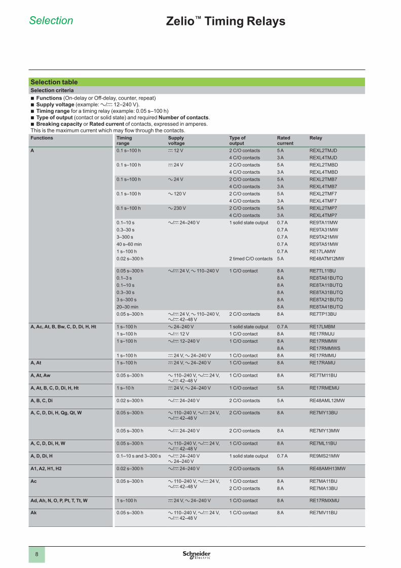
Selection tableSelection criteriab Functions (On-delay or Off-delay, counter, repeat)b Supply voltage (example: a/c 12–240 V).b Timing range for a timing relay (example: 0.05 s–100 h)b Type of output (contact or solid state) and required Number of contacts.b Breaking capacity or Rated current of contacts, expressed in amperes.This is the maximum current which may flow through the contacts. Functions Timing
rangeSupply voltage
Type of output
Rated current
Relay
A 0.1 s–100 h c 12 V 2 C/O contacts 5 A REXL2TMJD4 C/O contacts 3 A REXL4TMJD
0.1 s–100 h c 24 V 2 C/O contacts 5 A REXL2TMBD4 C/O contacts 3 A REXL4TMBD
0.1 s–100 h a 24 V 2 C/O contacts 5 A REXL2TMB74 C/O contacts 3 A REXL4TMB7
0.1 s–100 h a 120 V 2 C/O contacts 5 A REXL2TMF74 C/O contacts 3 A REXL4TMF7
0.1 s–100 h a 230 V 2 C/O contacts 5 A REXL2TMP74 C/O contacts 3 A REXL4TMP7
0.1–10 s a/c 24–240 V 1 solid state output 0.7 A RE9TA11MW0.3–30 s 0.7 A RE9TA31MW3–300 s 0.7 A RE9TA21MW40 s–60 min 0.7 A RE9TA51MW1 s–100 h 0.7 A RE17LAMW0.02 s–300 h 2 timed C/O contacts 5 A RE48ATM12MW
0.05 s–300 h a/c 24 V, a 110–240 V 1 C/O contact 8 A RE7TL11BU0.1–3 s 8 A RE8TA61BUTQ0.1–10 s 8 A RE8TA11BUTQ0.3–30 s 8 A RE8TA31BUTQ3 s–300 s 8 A RE8TA21BUTQ20–30 min 8 A RE8TA41BUTQ0.05 s–300 h a/c 24 V, a 110–240 V,
a/c 42–48 V2 C/O contacts 8 A RE7TP13BU
A, Ac, At, B, Bw, C, D, Di, H, Ht 1 s–100 h a 24–240 V 1 solid state output 0.7 A RE17LMBM1 s–100 h a/c 12 V 1 C/O contact 8 A RE17RMJU1 s–100 h a/c 12–240 V 1 C/O contact 8 A RE17RMMW
8 A RE17RMMWS1 s–100 h c 24 V, a 24–240 V 1 C/O contact 8 A RE17RMMU
A, At 1 s–100 h c 24 V, a 24–240 V 1 C/O contact 8 A RE17RAMU
A, At, Aw 0.05 s–300 h a 110–240 V, a/c 24 V, a/c 42–48 V
1 C/O contact 8 A RE7TM11BU
A, At, B, C, D, Di, H, Ht 1 s–10 h c 24 V, a 24–240 V 1 C/O contact 5 A RE17RMEMU
A, B, C, Di 0.02 s–300 h a/c 24–240 V 2 C/O contacts 5 A RE48AML12MW
A, C, D, Di, H, Qg, Qt, W 0.05 s–300 h a 110–240 V, a/c 24 V, a/c 42–48 V
2 C/O contacts 8 A RE7MY13BU
0.05 s–300 h a/c 24–240 V 2 C/O contacts 8 A RE7MY13MW
A, C, D, Di, H, W 0.05 s–300 h a 110–240 V, a/c 24 V, a/c 42–48 V
1 C/O contact 8 A RE7ML11BU
A, D, Di, H 0.1–10 s and 3–300 s a/c 24–240 Va 24–240 V
1 solid state output 0.7 A RE9MS21MW
A1, A2, H1, H2 0.02 s–300 h a/c 24–240 V 2 C/O contacts 5 A RE48AMH13MW
Ac 0.05 s–300 h a 110–240 V, a/c 24 V, a/c 42–48 V
1 C/O contact 8 A RE7MA11BU2 C/O contacts 8 A RE7MA13BU
Ad, Ah, N, O, P, Pt, T, Tt, W 1 s–100 h c 24 V, a 24–240 V 1 C/O contact 8 A RE17RMXMU
Ak 0.05 s–300 h a 110–240 V, a/c 24 V, a/c 42–48 V
1 C/O contact 8 A RE7MV11BU
Zelio™ Timing Relays
9
Selection (continued)
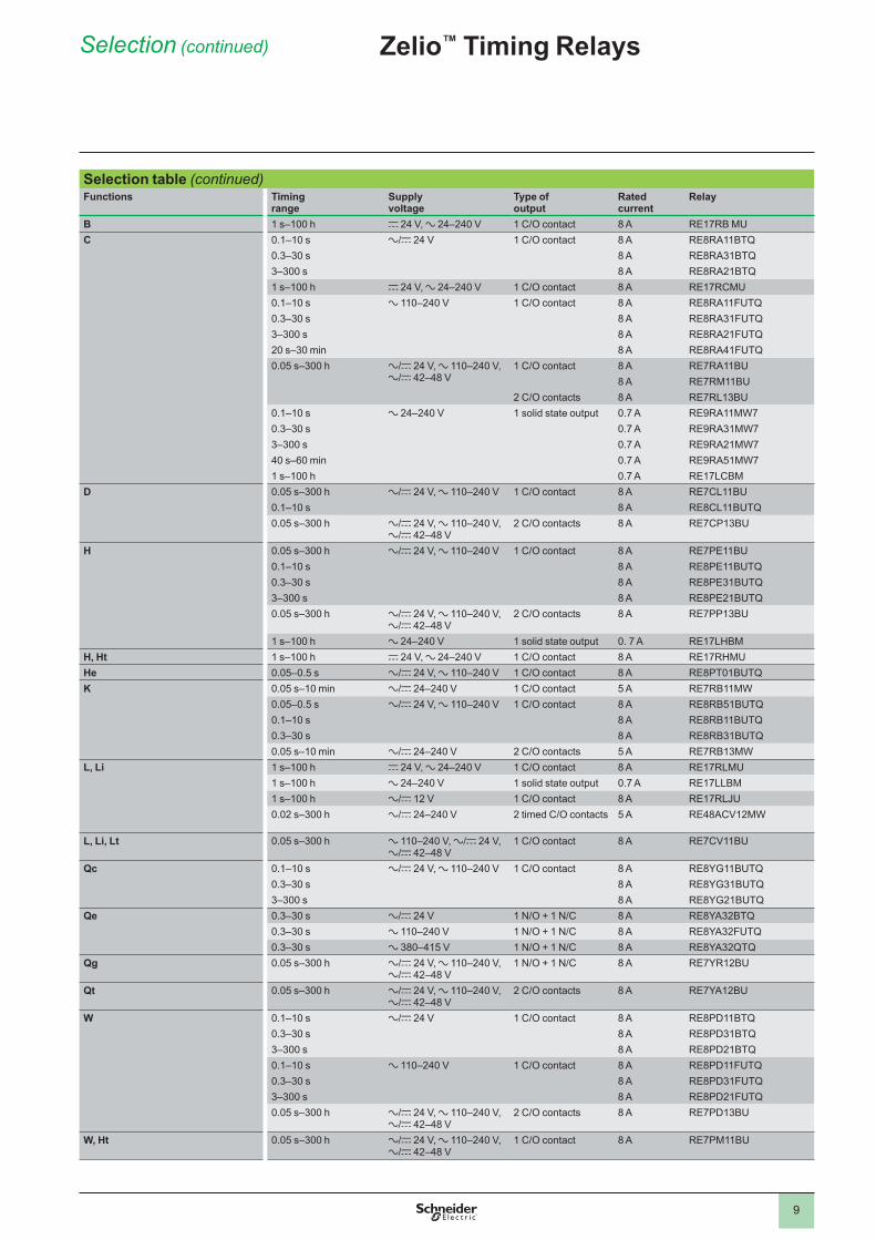
Selection table (continued)Functions Timing
rangeSupply voltage
Type of output
Rated current
Relay
B 1 s–100 h c 24 V, a 24–240 V 1 C/O contact 8 A RE17RB MUC 0.1–10 s a/c 24 V 1 C/O contact 8 A RE8RA11BTQ
0.3–30 s 8 A RE8RA31BTQ3–300 s 8 A RE8RA21BTQ1 s–100 h c 24 V, a 24–240 V 1 C/O contact 8 A RE17RCMU0.1–10 s a 110–240 V 1 C/O contact 8 A RE8RA11FUTQ0.3–30 s 8 A RE8RA31FUTQ3–300 s 8 A RE8RA21FUTQ20 s–30 min 8 A RE8RA41FUTQ0.05 s–300 h a/c 24 V, a 110–240 V,
a/c 42–48 V1 C/O contact 8 A RE7RA11BU
8 A RE7RM11BU2 C/O contacts 8 A RE7RL13BU
0.1–10 s a 24–240 V 1 solid state output 0.7 A RE9RA11MW70.3–30 s 0.7 A RE9RA31MW73–300 s 0.7 A RE9RA21MW740 s–60 min 0.7 A RE9RA51MW71 s–100 h 0.7 A RE17LCBM
D 0.05 s–300 h a/c 24 V, a 110–240 V 1 C/O contact 8 A RE7CL11BU0.1–10 s 8 A RE8CL11BUTQ0.05 s–300 h a/c 24 V, a 110–240 V,
a/c 42–48 V2 C/O contacts 8 A RE7CP13BU
H 0.05 s–300 h a/c 24 V, a 110–240 V 1 C/O contact 8 A RE7PE11BU0.1–10 s 8 A RE8PE11BUTQ0.3–30 s 8 A RE8PE31BUTQ3–300 s 8 A RE8PE21BUTQ0.05 s–300 h a/c 24 V, a 110–240 V,
a/c 42–48 V2 C/O contacts 8 A RE7PP13BU
1 s–100 h a 24–240 V 1 solid state output 0. 7 A RE17LHBMH, Ht 1 s–100 h c 24 V, a 24–240 V 1 C/O contact 8 A RE17RHMUHe 0.05–0.5 s a/c 24 V, a 110–240 V 1 C/O contact 8 A RE8PT01BUTQK 0.05 s–10 min a/c 24–240 V 1 C/O contact 5 A RE7RB11MW
0.05–0.5 s a/c 24 V, a 110–240 V 1 C/O contact 8 A RE8RB51BUTQ0.1–10 s 8 A RE8RB11BUTQ0.3–30 s 8 A RE8RB31BUTQ0.05 s–10 min a/c 24–240 V 2 C/O contacts 5 A RE7RB13MW
L, Li 1 s–100 h c 24 V, a 24–240 V 1 C/O contact 8 A RE17RLMU1 s–100 h a 24–240 V 1 solid state output 0.7 A RE17LLBM1 s–100 h a/c 12 V 1 C/O contact 8 A RE17RLJU0.02 s–300 h a/c 24–240 V 2 timed C/O contacts 5 A RE48ACV12MW
L, Li, Lt 0.05 s–300 h a 110–240 V, a/c 24 V, a/c 42–48 V
1 C/O contact 8 A RE7CV11BU
Qc 0.1–10 s a/c 24 V, a 110–240 V 1 C/O contact 8 A RE8YG11BUTQ0.3–30 s 8 A RE8YG31BUTQ3–300 s 8 A RE8YG21BUTQ
Qe 0.3–30 s a/c 24 V 1 N/O + 1 N/C 8 A RE8YA32BTQ0.3–30 s a 110–240 V 1 N/O + 1 N/C 8 A RE8YA32FUTQ0.3–30 s a 380–415 V 1 N/O + 1 N/C 8 A RE8YA32QTQ
Qg 0.05 s–300 h a/c 24 V, a 110–240 V, a/c 42–48 V
1 N/O + 1 N/C 8 A RE7YR12BU
Qt 0.05 s–300 h a/c 24 V, a 110–240 V, a/c 42–48 V
2 C/O contacts 8 A RE7YA12BU
W 0.1–10 s a/c 24 V 1 C/O contact 8 A RE8PD11BTQ0.3–30 s 8 A RE8PD31BTQ3–300 s 8 A RE8PD21BTQ0.1–10 s a 110–240 V 1 C/O contact 8 A RE8PD11FUTQ0.3–30 s 8 A RE8PD31FUTQ3–300 s 8 A RE8PD21FUTQ0.05 s–300 h a/c 24 V, a 110–240 V,
a/c 42–48 V2 C/O contacts 8 A RE7PD13BU
W, Ht 0.05 s–300 h a/c 24 V, a 110–240 V, a/c 42–48 V
1 C/O contact 8 A RE7PM11BU
Zelio™ Timing Relays

10
Functions
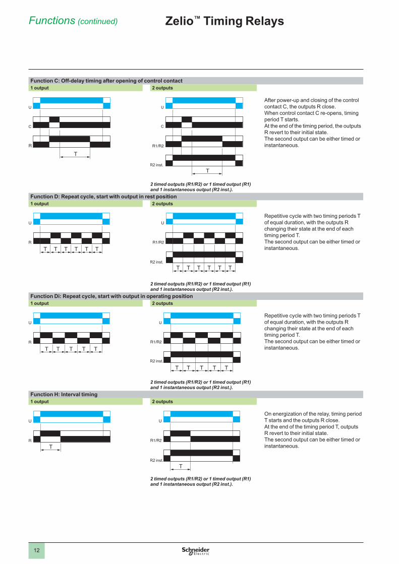
FunctionsU: SupplyR: Relay or solid state outputR1/R2: 2 timed outputsR2 inst.: The second output can be configured to be instantaneous.T: Timing periodC: Control contactG: GateTa: Adjustable On-delayTr: Adjustable Off-delay
Function diagram :Relay de-energizedRelay energizedOutput openOutput closed
Function A: Delay on energization 1 output 2 outputs
The timing period T begins on energization.After timing, the outputs R close.The second output can be either timed or instantaneous.
2 timed outputs (R1/R2) or 1 timed output (R1) and 1 instantaneous output (R2 inst.).
Function Ac: Timing after closing and opening of control contact 1 output 2 outputs
After power-up, closing of the control contact C causes the timing period T to start (timing can be interrupted by operating the Gate control contact G). At the end of this timing period, the relay closes.When control contact C re-opens, the timing period T starts.At the end of this timing period T, the outputs R revert to their initial position (timing can be interrupted by operating the Gate control contact G).The second output can be either timed or instantaneous.
T = t1 + t2 + …T = t’1 + t’2 + …
2 timed outputs (R1/R2) or 1 timed output (R1) and 1 instantaneous output (R2 inst.).
Function Ad: Timing on closing of control contact
After power-up, pulsing or maintaining control contact C starts the timing period T.At the end of this timing period T, the output R closes. The output R will be reset the next time control contact C is pulsed or maintained.
Function Ah: Repeat single cycle by operation of control contact
After power-up, pulsing or maintaining control contact C starts the timing period T.A single cycle then starts with 2 timing periods T of equal duration (start with output in rest position).Output R changes state at the end of the first timing period T and reverts to its initial position at the end of the second timing period T.Control contact C must be reset in order to re-start the single repeat cycle.
U
RT
U
R1/R2
TR2 inst.
U
C
t1
G
Rt'1t2 t'2
U
C
R1/R2
T T
R2 inst.
U
R
C
T T
U
R
C
TT T T
Zelio™ Timing Relays

11
Functions (continued)
Functions (continued)Function Ak: Asymmetrical On-delay and Off-delay with external control
After power-up and closing of the control contact C, timing starts for a period Ta (timing can be interrupted by operating the Gate control contact G).At the end of this timing period Ta, the output R closes.Opening of control contact C causes a second timing period Tr to start (timing can be interrupted by operating the Gate control contact G).At the end of this timing period Tr, the output R reverts to its initial state.
Ta = t1 + t2 + …Tr = t’1 + t’2 + …Function At: Delay on energization with memory
After power-up, the first opening of control contact C starts the timing. Timing can be interrupted each time control contact C closes. When the cumulative total of time periods elapsed reaches the pre-set value T, the output relay closes.
T = t1 + t2 + …Function Aw: Off-delay when switch opens, time delay begins
The timing period T starts on energization.At the end of the timing period T, the output R closes.Closing control contact C opens output R. Opening control contact C restarts the timing period T. At the end of the timing period T, the output R closes.
Function B: Timing on impulse, one shot
After power-up, pulsing or maintaining control contact C starts the timing period T.The output R closes for the duration of the timing period T, then reverts to its initial state.
Function Bw: Pulse output (width adjustable)
On closing and opening of control contact C, the output R closes for the duration of the timing period T.
U
C
t1
G
R
t'1t2 t'2
U
R
C
t1 t2
U
R
C
T T
U
R
C
T T
U
R
C
T T
Zelio™ Timing Relays
12
Function C: Off-delay timing after opening of control contact 1 output 2 outputs
After power-up and closing of the control contact C, the outputs R close.When control contact C re-opens, timing period T starts.At the end of the timing period, the outputs R revert to their initial state.The second output can be either timed or instantaneous.
2 timed outputs (R1/R2) or 1 timed output (R1) and 1 instantaneous output (R2 inst.).
Function D: Repeat cycle, start with output in rest position1 output 2 outputs
Repetitive cycle with two timing periods T of equal duration, with the outputs R changing their state at the end of each timing period T.The second output can be either timed or instantaneous.
2 timed outputs (R1/R2) or 1 timed output (R1) and 1 instantaneous output (R2 inst.).
Function Di: Repeat cycle, start with output in operating position1 output 2 outputs
Repetitive cycle with two timing periods T of equal duration, with the outputs R changing their state at the end of each timing period T.The second output can be either timed or instantaneous.
2 timed outputs (R1/R2) or 1 timed output (R1) and 1 instantaneous output (R2 inst.).
Function H: Interval timing1 output 2 outputs
On energization of the relay, timing period T starts and the outputs R close.At the end of the timing period T, outputs R revert to their initial state.The second output can be either timed or instantaneous.
2 timed outputs (R1/R2) or 1 timed output (R1) and 1 instantaneous output (R2 inst.).
U
C
R
T
U
R1/R2
C
TR2 inst.
T T T T T T
U
R
U
R1/R2
T T T T T TR2 inst.
T T T T T
U
R
U
R1/R2
T T T T TR2 inst.
U
RT
U
R1/R2
TR2 inst.
Zelio™ Timing RelaysFunctions (continued)
13
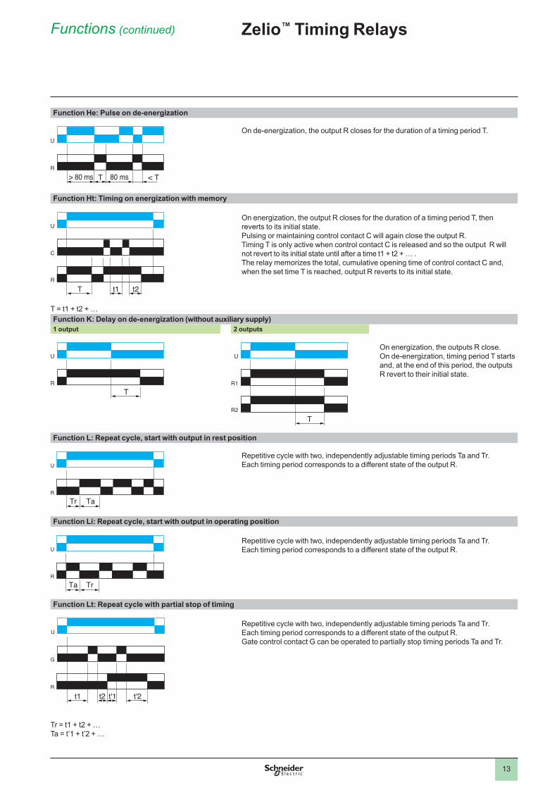
Function He: Pulse on de-energization
On de-energization, the output R closes for the duration of a timing period T.
Function Ht: Timing on energization with memory
On energization, the output R closes for the duration of a timing period T, then reverts to its initial state.Pulsing or maintaining control contact C will again close the output R.Timing T is only active when control contact C is released and so the output R will not revert to its initial state until after a time t1 + t2 + … .The relay memorizes the total, cumulative opening time of control contact C and, when the set time T is reached, output R reverts to its initial state.
T = t1 + t2 + …Function K: Delay on de-energization (without auxiliary supply)1 output 2 outputs
On energization, the outputs R close.On de-energization, timing period T starts and, at the end of this period, the outputs R revert to their initial state.
Function L: Repeat cycle, start with output in rest position
Repetitive cycle with two, independently adjustable timing periods Ta and Tr. Each timing period corresponds to a different state of the output R.
Function Li: Repeat cycle, start with output in operating position
Repetitive cycle with two, independently adjustable timing periods Ta and Tr. Each timing period corresponds to a different state of the output R.
Function Lt: Repeat cycle with partial stop of timing
Repetitive cycle with two, independently adjustable timing periods Ta and Tr. Each timing period corresponds to a different state of the output R.Gate control contact G can be operated to partially stop timing periods Ta and Tr.
Tr = t1 + t2 + … Ta = t’1 + t’2 + …
U
R> 80 ms 80 msT < T
U
R
C
t1 t2T
U
RT
U
R1
R2T
Tr Ta
U
R
Ta Tr
U
R
R
G
t1 t'2t2 t'1
U
Zelio™ Timing RelaysFunctions (continued)

14
Functions (continued) Zelio™ Timing Relays
Function N: Safeguard
After power-up and an initial control pulse C, the output R closes.If the interval between two control pulses C is greater than the set timing period T, timing elapses normally and the output R opens at the end of the timing period. If the interval is not greater than the set timing period, the output R remains closed until this condition is met.
Function O: Delayed safeguard
An initial timing period T begins on energization. At the end of this timing period, the output R closes. As soon as there is a control pulse C, the output R reverts to its initial state and remains in that state until the interval between two control pulses is less than the value of the set timing period T. Otherwise, the output R closes at the end of the timing period T.
Function P: Delayed fixed-length pulse
The timing period T starts on energization.At the end of this period, the output R closes for a fixed time P.
Function Pt: Impulse counter (On-delay)
On energization, timing period T starts (it can be interrupted by operating the Gate control contact G).At the end of this period, the output R closes for a fixed time P.
Function Qc: Star-delta timing
Timing for star delta starter with contact for switching to star connection.
Function Qe: Star-delta timing
On energization, the star contact closes instantly and timing starts. At the end of the timing period, the star contact opens.After an 80 ms pause, the delta contact closes and remains in this position.
T
U
C
R
T
T T T
U
C
Rt<T
U
RT P
P = 500 ms
t1 t2 P
U
G
R
T = t1 + t2 + …P = 500 ms
T 50 ms
U
R
T 80 ms
U
R1
R2

15
Functions (continued) Zelio™ Timing Relays
Function Qg: Star-delta timing
Timing for star delta starter with contact for switching to star connection.
Function Qt: Star-delta timing
Timing for star-delta starter with double On-delay period.
Function T: Bistable relay
After power-up, pulsing or maintaining of control contact C turns on the output R.A second pulse on the control contact C turns off the output R.
Function Tt: Timed impulse relay
After power-up, pulsing or maintaining control contact C turns on output R and starts the timing.The output turns off at the end of the timing period T or following a second pulse on the control contact C.
Function W: On-delay after opening of control contact1 output 2 outputs
After power-up and opening of the control contact, the outputs R close for a timing period T.At the end of this timing period, the outputs revert to their initial state.The second output can be either timed or instantaneous.
2 timed outputs (R1/R2) or 1 timed output (R1) and 1 instantaneous output (R2 inst.).
T T50 ms
U
R1
R2
U
R1
R2T T
50 ms
U
C
R
U
C
RT t<T
T
U
C
R
U
C
R1/R2
TR2 inst.

16
Catalog numbers Zelio™ Timing RelaysModular relays with solid state or relay output, width 17.5 mm (0.7 in.)
Modular relays with solid state output 0.7 ASingle functionTiming ranges Functions Voltages Catalog number Weight
V kg (lb)1 s, 10 s, 1 min, 10 min, 1 h, 10 h, 100 h
A z 24–240 RE17LAMW 0.060 (0.13)
H a 24–240 RE17LHBM 0.060 (0.13)
C a 24–240 RE17LCBM 0.060 (0.13)
Dual function1 s, 10 s, 1 min, 10 min, 1 h, 10 h, 100 h
L, Li
a 24–240 RE17LLBM 0.060 (0.13)
Multifunction1 s, 10 s, 1 min, 10 min, 1 h, 10 h, 100 h
A, At, B, C, H, Ht, D, Di, Ac, Bw
a 24–240 RE17LMBM 0.060 (0.13)
Modular relays with relay output, 1 C/O contactSingle functionTiming ranges Functions Voltages Catalog number Weight
V kg (lb)1 s, 10 s, 1 min, 10 min, 1 h, 10 h, 100 h
B z 24–240 RE17RBMU 0.060 (0.13)
C z 24–240 RE17RCMU 0.060 (0.13)
Dual function1 s, 10 s, 1 min, 10 min, 1 h, 10 h, 100 h
A, At
z 24–240 RE17RAMU 0.060 (0.13)
H, Ht
z 24–240 RE17RHMU 0.060 (0.13)
L, Li
z 24–240 RE17RLMU 0.060 (0.13)
z 12 RE17RLJU 0.060 (0.13)
Multifunction1 s, 10 s, 1 min, 10 min, 1 h, 10 h, 100 h
A, At, B, C, H, Ht, D, Di, Ac, Bw
z 12 RE17RMJU 0.060 (0.13)
z 24–240 RE17RMMU 0.060 (0.13)
z 12–240 RE17RMMW 0.060 (0.13)
RE17RMMWS 0.060 (0.13)
Ad, Ah, N, O, P, Pt, T, Tt, W
z 24–240 RE17RMXMU 0.060 (0.13)
1 s, 10 s, 1 min 10 min, 1 h, 10 h
A, At, B, C, H, Ht, D, Di
z 24–240 RE17RMEMU 0.060 (0.13)
Solid state outputv Multifunction, dual function, or single functionv Multi-range (7 selectable ranges)v Multivoltagev Solid state output: 0.7 Av Screw terminals
Relay output, 1 C/O contactv Dual function or single functionv Multi-range (7 selectable ranges)v Multivoltagev 1 relay output: 8 Av Screw terminalsv State indication by 1 LEDv Option of supplying a load in parallelv 3-wire sensor control option
NOTE: Detailed function descriptions begin on page 10. Dimensions and wiring diagrams begin on page 26.
RE17LAMW RE17LLBM
RE17RpMp
17
Catalog numbersSingle functionTiming ranges
Functions Voltages Catalog number Weight
V kg (lb)0.1–10 s A z 24–240 V RE9TA11MW 0.110
(0.24)C z 24–240 V RE9RA11MW7 0.110
(0.24)0.3–30 s A z 24–240 V RE9TA31MW 0.110
(0.24)C z 24–240 V RE9RA31MW7 0.110
(0.24)3–300 s A z 24–240 V RE9TA21MW 0.110
(0.24)C z 24–240 V RE9RA21MW7 0.110
(0.24)40 s–60 min A z 24–240 V RE9TA51MW 0.110
(0.24)C z 24–240 V RE9RA51MW7 0.110
(0.24)Multifunction
0.1–10 s,0.3–30 s
A z 24–240 V RE9MS21MW 0.110 (0.24)H,
D, Di
a 24–240 V
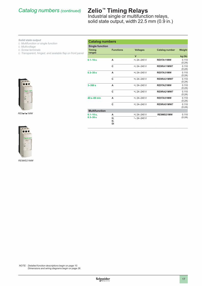
Zelio™ Timing RelaysIndustrial single or multifunction relays, solid state output, width 22.5 mm (0.9 in.)
Catalog numbers (continued)
Solid state outputv Multifunction or single functionv Multivoltagev Screw terminalsv Transparent, hinged, and sealable flap on front panel
NOTE: Detailed function descriptions begin on page 10. Dimensions and wiring diagrams begin on page 26.
RE9pAp1MW
RE9MS21MW
18
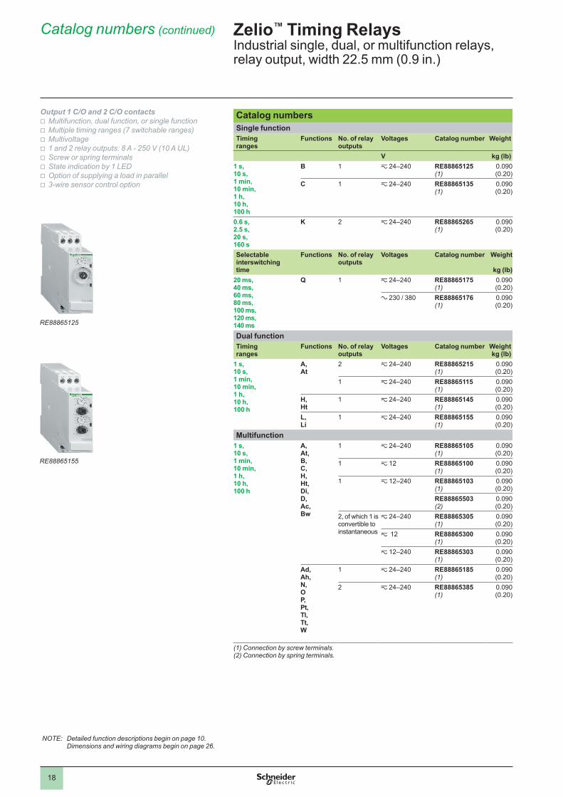
Catalog numbersSingle functionTiming ranges
Functions No. of relay outputs
Voltages Catalog number Weight
V kg (lb)1 s, 10 s, 1 min, 10 min, 1 h, 10 h, 100 h
B 1 z 24–240 RE88865125(1)
0.090 (0.20)
C 1 z 24–240 RE88865135(1)
0.090 (0.20)
0.6 s, 2.5 s, 20 s, 160 s
K 2 z 24–240 RE88865265(1)
0.090 (0.20)
Selectable interswitching time
Functions No. of relay outputs
Voltages Catalog number Weight
kg (lb)20 ms, 40 ms, 60 ms, 80 ms, 100 ms, 120 ms, 140 ms
Q 1 z 24–240 RE88865175(1)
0.090 (0.20)
a 230 / 380 RE88865176(1)
0.090 (0.20)
Dual functionTiming ranges
Functions No. of relay outputs
Voltages Catalog number Weight kg (lb)
1 s, 10 s, 1 min, 10 min, 1 h, 10 h, 100 h
A, At
2 z 24–240 RE88865215(1)
0.090 (0.20)
1 z 24–240 RE88865115(1)
0.090 (0.20)
H, Ht
1 z 24–240 RE88865145(1)
0.090 (0.20)
L, Li
1 z 24–240 RE88865155(1)
0.090 (0.20)
Multifunction1 s, 10 s, 1 min, 10 min, 1 h, 10 h, 100 h
A, At, B, C, H, Ht, Di, D, Ac, Bw
1 z 24–240 RE88865105(1)
0.090 (0.20)
1 z 12 RE88865100(1)
0.090 (0.20)
1 z 12–240 RE88865103(1)
0.090 (0.20)
RE88865503(2)
0.090 (0.20)
2, of which 1 is convertible to instantaneous
z 24–240 RE88865305(1)
0.090 (0.20)
z 12 RE88865300(1)
0.090 (0.20)
z 12–240 RE88865303(1)
0.090 (0.20)
Ad, Ah, N, O P, Pt, Tl, Tt, W
1 z 24–240 RE88865185(1)
0.090 (0.20)
2 z 24–240 RE88865385(1)
0.090 (0.20)
(1) Connection by screw terminals.(2) Connection by spring terminals.
Zelio™ Timing RelaysIndustrial single, dual, or multifunction relays, relay output, width 22.5 mm (0.9 in.)
Catalog numbers (continued)
Output 1 C/O and 2 C/O contactsv Multifunction, dual function, or single functionv Multiple timing ranges (7 switchable ranges)v Multivoltagev 1 and 2 relay outputs: 8 A - 250 V (10 A UL)v Screw or spring terminalsv State indication by 1 LEDv Option of supplying a load in parallelv 3-wire sensor control option
NOTE: Detailed function descriptions begin on page 10. Dimensions and wiring diagrams begin on page 26.
RE88865125
RE88865155

19
Catalog numbersTiming ranges
Functions No. of relay outputs
Voltages Catalog number Weight
V kg (lb)0.05 s–300 h(10 ranges)
A, Aw, At
1 z 24, a 110–240, z 42–48
RE7TM11BU 0.150 (0.33)
Ac 1 z 24, a 110–240, z 42–48
RE7MA11BU 0.150 (0.33)
2 z 24, a 110–240, z 42–48
RE7MA13BU(timing periods are equal)
0.150 (0.33)
Ak 1 z 24, a 110–240, z 42–48
RE7MV11BU 0.150 (0.33)
C 1 z 24, a 110–240, z 42–48
RE7RA11BU 0.150 (0.33)
1 z 24, a 110–240, z 42–48
RE7RM11BUdry (voltage free) contact
0.150 (0.33)
2 z 24, a 110–240, z 42–48
RE7RL13BUdry (voltage free) contact
0.150 (0.33)
Ht, W
1 z 24, a 110–240, z 42–48
RE7PM11BU 0.150 (0.33)
L, Li, Lt
1 z 24, a 110–240, z 42–48
RE7CV11BU 0.150 (0.33)
A, C, H, W, D, Di
1 z 24, a 110–240, z 42–48
RE7ML11BU 0.150 (0.33)
A 1 z 24, a 110…240
RE7TL11BU 0.150 (0.33)
2 z 24, a 110–240, z 42–48
RE7TP13BU 0.150 (0.33)
H 1 z 24, a 110–240
RE7PE11BU 0.150 (0.33)
2 z 24, a 110–240, z 42–48
RE7PP13BU 0.150 (0.33)
D 1 z 24, a 110–240
RE7CL11BU 0.150 (0.33)
2 z 24, a 110–240, z 42–48
RE7CP13BU 0.150 (0.33)
W 2 z 24, a 110–240, z 42–48
RE7PD13BU 0.150 (0.33)
Qt 2 z 24, a 110–240, z 42–48
RE7YA12BU 0.150 (0.33)
Qg 2 z 24, a 110–240, z 42–48
RE7YR12BU 0.150 (0.33)
A, C, H, W, D, Di, Qg, Qt
2 z 24, a 110–240, z 42–48
RE7MY13BU 0.150 (0.33)
2 z 24–240 RE7MY13MW 0.150 (0.33)
0.05 s–10 min(7 ranges)
K 1 z 24–240 RE7RB11MW 0.150 (0.33)
2 z 24–240 RE7RB13MW 0.150 (0.33)
Zelio™ Timing RelaysIndustrial single, dual, or multifunction relays, relay output, width 22.5 mm (0.9 in.)
Catalog numbers (continued)
Output 1 C/O and 2 C/O contactsv Multifunction, dual function, or single functionv Multiple timing rangesv Multivoltagev Transparent, hinged, and sealable flap on front panel
NOTE: Detailed function descriptions begin on page 10. Dimensions and wiring diagrams begin on page 26.
RE7TM11BU
RE7MA11BU
RE7CV11BU
20
Catalog numbersTiming ranges
Functions Voltages Catalog number Weight
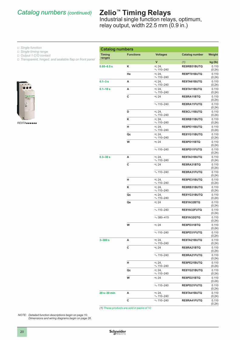
V (1) kg (lb)0.05–0.5 s K z 24,
a 110–240RE8RB51BUTQ 0.110
(0.24)He z 24,
a 110–240RE8PT01BUTQ 0.110
(0.24)0.1–3 s A z 24,
a 110–240RE8TA61BUTQ 0.110
(0.24)0.1–10 s A z 24,
a 110–240RE8TA11BUTQ 0.110
(0.24)C z 24 RE8RA11BTQ 0.110
(0.24)a 110–240 RE8RA11FUTQ 0.110
(0.24)D z 24,
a 110–240RE8CL11BUTQ 0.110
(0.24)K z 24,
a 110–240RE8RB11BUTQ 0.110
(0.24)H z 24,
a 110–240RE8PE11BUTQ 0.110
(0.24)Qc z 24,
a 110–240RE8YG11BUTQ 0.110
(0.24)W z 24 RE8PD11BTQ 0.110
(0.24)a 110–240 RE8PD11FUTQ 0.110
(0.24)0.3–30 s A z 24,
a 110–240RE8TA31BUTQ 0.110
(0.24)C z 24 RE8RA31BTQ 0.110
(0.24)a 110–240 RE8RA31FUTQ 0.110
(0.24)H z 24,
a 110–240RE8PE31BUTQ 0.110
(0.24)K z 24,
a 110–240RE8RB31BUTQ 0.110
(0.24)Qc z 24,
a 110–240RE8YG31BUTQ 0.110
(0.24)Qe z 24 RE8YA32BTQ 0.110
(0.24)a 110–240 RE8YA32FUTQ 0.110
(0.24)a 380–415 RE8YA32QTQ 0.110
(0.24)W z 24 RE8PD31BTQ 0.110
(0.24)a 110–240 RE8PD31FUTQ 0.110
(0.24)3–300 s A z 24,
a 110–240RE8TA21BUTQ 0.110
(0.24)C z 24 RE8RA21BTQ 0.110
(0.24)a 110–240 RE8RA21FUTQ 0.110
(0.24)H z 24,
a 110–240RE8PE21BUTQ 0.110
(0.24)Qc z 24,
a 110–240RE8YG21BUTQ 0.110
(0.24)W z 24 RE8PD21BTQ 0.110
(0.24)a 110–240 RE8PD21FUTQ 0.110
(0.24)20 s–30 min A z 24,
a 110–240RE8TA41BUTQ 0.110
(0.24)C a 110–240 RE8RA41FUTQ 0.110
(0.24)(1) These products are sold in packs of 10
Zelio™ Timing RelaysIndustrial single function relays, optimum, relay output, width 22.5 mm (0.9 in.)
Catalog numbers (continued)
v Single functionv Single timing rangev Output 1 C/O contactv Transparent, hinged, and sealable flap on front panel
NOTE: Detailed function descriptions begin on page 10. Dimensions and wiring diagrams begin on page 26.
RE8TApppppp
21
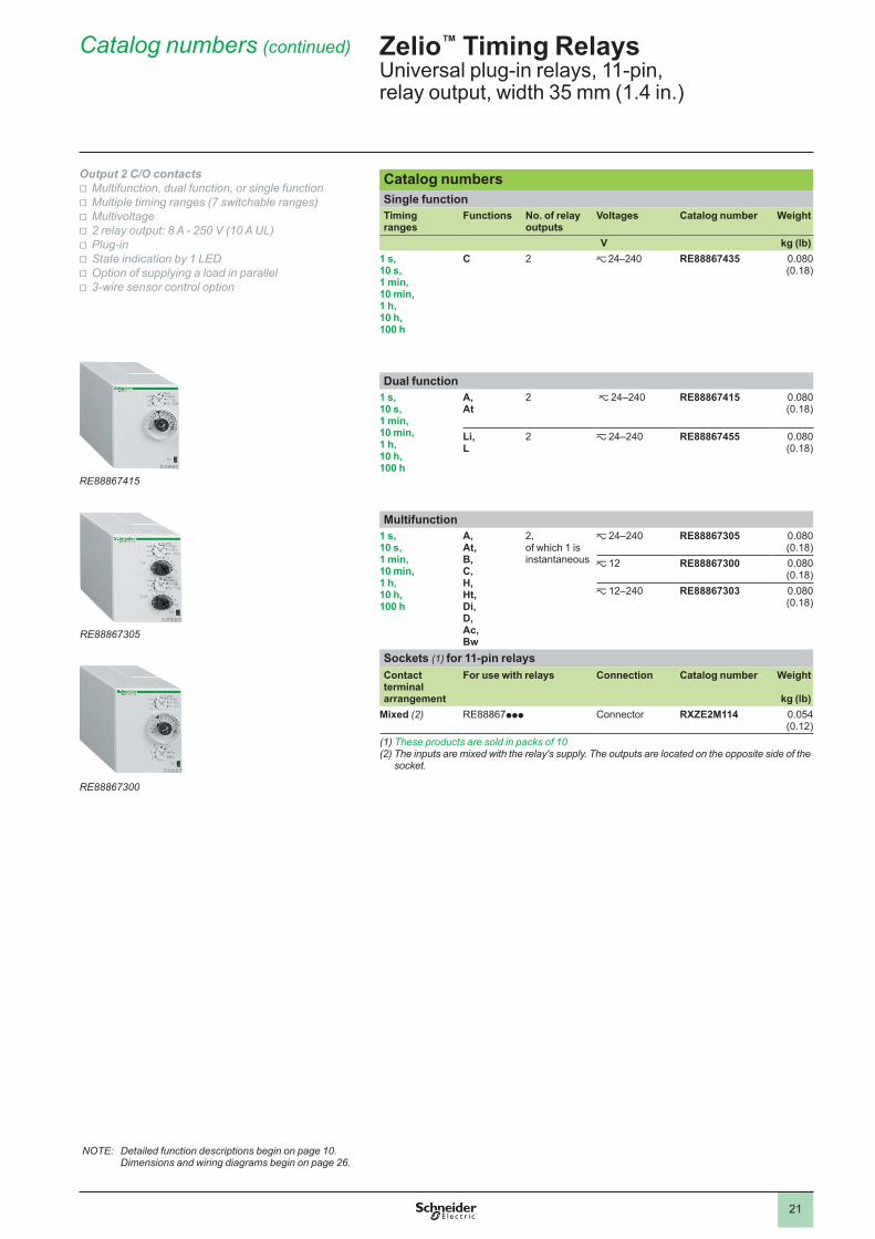
Catalog numbersSingle functionTiming ranges
Functions No. of relay outputs
Voltages Catalog number Weight
V kg (lb)1 s, 10 s, 1 min, 10 min, 1 h, 10 h, 100 h
C 2 z 24–240 RE88867435 0.080 (0.18)
Dual function1 s, 10 s, 1 min, 10 min, 1 h, 10 h, 100 h
A, At
2 z 24–240 RE88867415 0.080 (0.18)
Li, L
2 z 24–240 RE88867455 0.080 (0.18)
Multifunction1 s, 10 s, 1 min, 10 min, 1 h, 10 h, 100 h
A, At, B, C, H, Ht, Di, D, Ac, Bw
2, of which 1 is instantaneous
z 24–240 RE88867305 0.080 (0.18)
z 12 RE88867300 0.080 (0.18)
z 12–240 RE88867303 0.080 (0.18)
Sockets (1) for 11-pin relaysContact terminal arrangement
For use with relays Connection Catalog number Weight
kg (lb)Mixed (2) RE88867ppp Connector RXZE2M114 0.054
(0.12)(1) These products are sold in packs of 10(2) The inputs are mixed with the relay's supply. The outputs are located on the opposite side of the
socket.
Zelio™ Timing RelaysUniversal plug-in relays, 11-pin, relay output, width 35 mm (1.4 in.)
Catalog numbers (continued)
Output 2 C/O contactsv Multifunction, dual function, or single functionv Multiple timing ranges (7 switchable ranges)v Multivoltagev 2 relay output: 8 A - 250 V (10 A UL)v Plug-inv State indication by 1 LEDv Option of supplying a load in parallelv 3-wire sensor control option
NOTE: Detailed function descriptions begin on page 10. Dimensions and wiring diagrams begin on page 26.
RE88867305
RE88867415
RE88867300

22
Catalog numbersSingle functionTiming ranges
Functions No. of relay outputs
Voltages Catalog number Weight
V kg (lb)1 s, 10 s , 1 min, 10 min, 1 h, 10 h, 100 h
A
2 z 24–240 RE88867215 0.080 (0.18)
C 1 z 24–240 RE88867135 0.080 (0.18)
Dual function1 s, 10 s, 1 min, 10 min, 1 h, 10 h, 100 h
Li, L
1 z 24–240 RE88867155 0.080 (0.18)
Multifunction1 s, 10 s, 1 min, 10 min, 1 h, 10 h, 100 h
A, At, B, C, H, Ht, Di, D, Ac, Bw
1 z 24–240 RE88867105 0.080 (0.18)
z 12 RE88867100 0.080 (0.18)
z 12–240 RE88867103 0.080 (0.18)
Sockets (1) for 8-pin relaysContact terminal arrangement
For use with relays Catalog number Weight
kg (lb)Mixed (2) RE888671pp,
RE888672pp RUZC2M 0.054
(0.12)
(1) These products are sold in packs of 10.(2) The inputs are mixed with the relay’s supply. The outputs are located on the opposite side of the
socket.
Zelio™ Timing RelaysUniversal plug-in relays, 8-pin, relay output, width 35 mm (1.4 in.)
Catalog numbers (continued)
Output 1 C/O or 2 C/O contactsv Multifunction, dual function, or single functionv Multiple timing ranges (7 switchable ranges)v Multivoltagev 1 or 2 relay outputs: 8 A - 250 V (10 A UL) v Plug-inv State indication by 1 LEDv Option of supplying a load in parallelv 3-wire sensor control option
NOTE: Detailed function descriptions begin on page 10. Dimensions and wiring diagrams begin on page 26.
RE88867215
RE88867155
RE88867105

23
Catalog numbersSingle functionTiming ranges
Functions No. of relay outputs
Voltages Catalog number Weight
V kg (lb)0.1–1 s, 1–10 s, 0.1–1 min, 1–10 min, 0.1–1 h, 1–10 h, 10–100 h(7 switchable ranges)
A 2 c 12 REXL2TMJD 0.050 (0.11)
c 24 REXL2TMBD 0.050 (0.11)
a 24 (50/60 Hz) REXL2TMB7 0.050 (0.11)
a 120 (50/60 Hz) REXL2TMF7 0.050 (0.11)
a 230 (50/60 Hz) REXL2TMP7 0.050 (0.11)
4 c 12 REXL4TMJD 0.050 (0.11)
c 24 (1)
REXL4TMBD 0.050 (0.11)
a 24 (50/60 Hz)(1)
REXL4TMB7 0.050 (0.11)
a 120 (50/60 Hz) REXL4TMF7 0.050 (0.11)
a 230 (50/60 Hz) REXL4TMP7 0.050 (0.11)
Sockets (2) for relaysContact terminal arrangement
For use with relays Connection Catalog number Weight
kg (lb)Mixed (3) REXL2TMpp,
REXL4TMpp Screw clamp RXZE2M114
(5)0.048 (0.11)
REXL2TMpp, REXL4TMpp
Connector RXZE2M114M(6)
0.056 (0.12)
Separate (4) REXL2TMpp Connector RXZES108M 0.070 (0.15)
REXL4TMpp Connector RXZE2S114M 0.058 (0.13)
(1) For c 48 V supply, additional resistor 560 W 2 W / c 24 V. For a 48 V, additional resistor 390 W 4 W / a 24 V.
(2) These products are sold in packs of 10.(3) The inputs are mixed with the relay’s supply. The outputs are located on the opposite side of the
socket.(4) The inputs and outputs are separated from the relay supply.(5) Thermal current Ith: 10 A.(6) Thermal current Ith: 12 A.
Zelio™ Timing RelaysMiniature plug-in relays, relay output
Catalog numbers (continued)
Output, 2 C/O and 4 C/O contactsv Miniature and plug-in (21 x 27 mm)v Single function: function A = delay on energizationv Rated current a 5 Av 7 timing ranges (0.1 s to 100 h)v Multivoltagev Excellent immunity to interferencev Power on and relay energized indication by 2 LEDs
NOTE: Detailed function descriptions begin on page 10. Dimensions and wiring diagrams begin on page 26.
REXL4TMpp
REXL2TMpp

24
Catalog numbers8-pin relayTiming ranges Function No. of relay
outputsVoltages Catalog number Weight
V kg (lb)1.2 s, 3 s, 12 s, 30 s, 120 s, 300 s, 12 min, 30 min, 120 min, 300 min, 12 h, 30 h, 120 h, 300 h
A
1 z 24–240 RE48ATM12MW 0.140 (0.31)
A1, A2, H1, H2
2, of which 1 is instantaneous
z 24–240 RE48AMH13MW 0.140 (0.31)
11-pin relay1.2 s, 3 s, 12 s, 30 s, 120 s, 300 s, 12 min, 30 min, 120 min, 300 min, 12 h, 30 h, 120 h, 300 h
L, Li
2 z 24–240 RE48ACV12MW 0.140 (0.31)
A, B, C, Di
2 z 24–240 RE48AML12MW 0.140 (0.31)
Catalog numbers (continued) Zelio™ Timing RelaysAnalog, electronic relays, relay output, 48 x 48
Output 2 C/O contactsv Time unit selector knobv Multifunction, single function, or dual functionv Multirangev Multivoltage v 2 relay outputs, 5 Av Panel-mounted or plug-inv LED indication
NOTE: Detailed function descriptions begin on page 10. Dimensions and wiring diagrams begin on page 26.
RE48ATM12MW
RE48AMH13MW
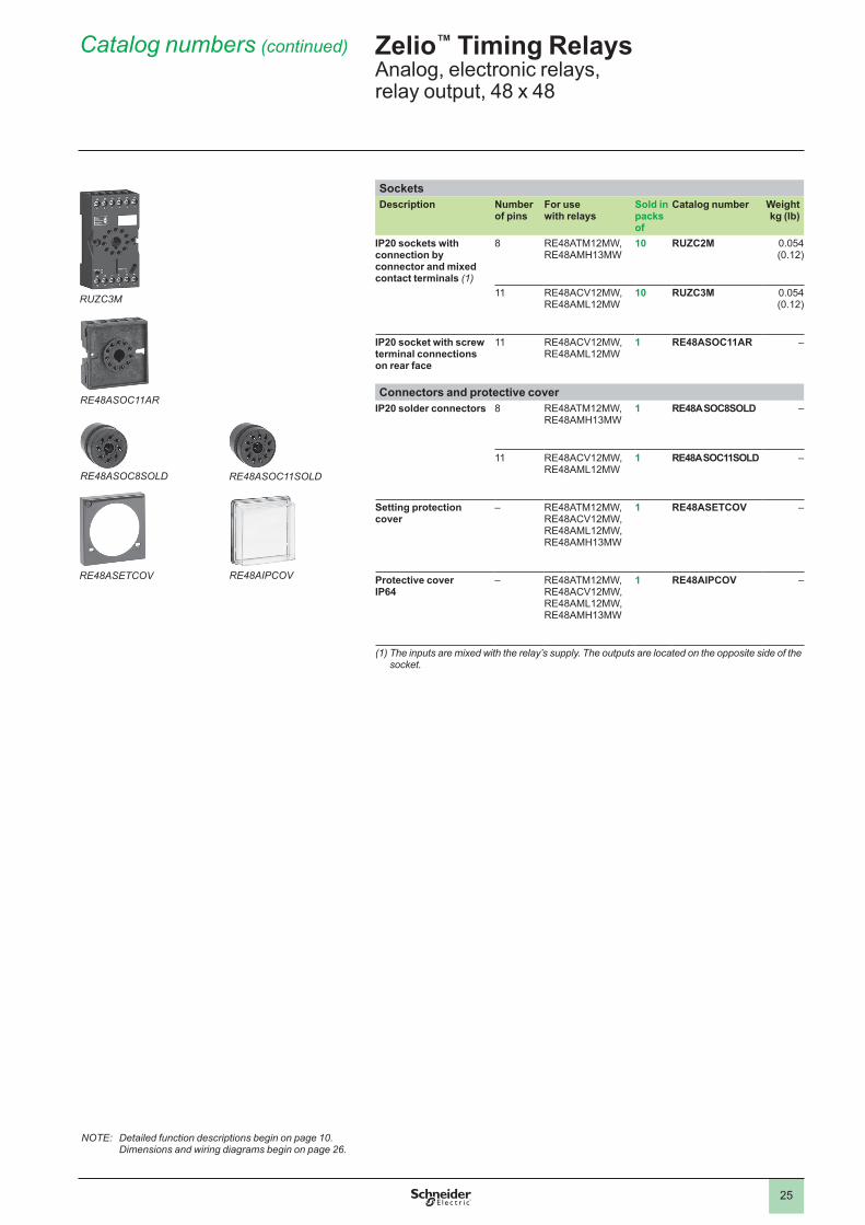
25
SocketsDescription Number
of pinsFor use with relays
Sold in packs of
Catalog number Weightkg (lb)
IP20 sockets with connection by connector and mixed contact terminals (1)
8 RE48ATM12MW, RE48AMH13MW
10 RUZC2M 0.054 (0.12)
11 RE48ACV12MW, RE48AML12MW
10 RUZC3M 0.054 (0.12)
IP20 socket with screw terminal connections on rear face
11 RE48ACV12MW, RE48AML12MW
1 RE48ASOC11AR –
Connectors and protective coverIP20 solder connectors 8 RE48ATM12MW,
RE48AMH13MW1 RE48A SOC8SOLD –
11 RE48ACV12MW, RE48AML12MW
1 RE48A SOC11SOLD –
Setting protection cover
– RE48ATM12MW, RE48ACV12MW, RE48AML12MW, RE48AMH13MW
1 RE48ASETCOV –
Protective coverIP64
– RE48ATM12MW, RE48ACV12MW, RE48AML12MW, RE48AMH13MW
1 RE48AIPCOV –
(1) The inputs are mixed with the relay’s supply. The outputs are located on the opposite side of the socket.
RUZC3M
RE48ASOC11AR
RE48ASOC8SOLD RE48ASOC11SOLD
RE48ASETCOV RE48AIPCOV
Catalog numbers (continued) Zelio™ Timing RelaysAnalog, electronic relays, relay output, 48 x 48
NOTE: Detailed function descriptions begin on page 10. Dimensions and wiring diagrams begin on page 26.
26
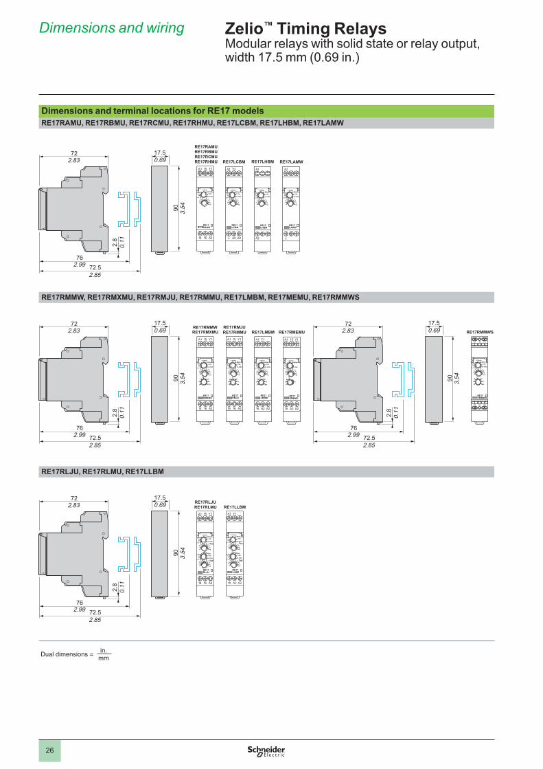
Dimensions and wiring
Dimensions and terminal locations for RE17 modelsRE17RAMU, RE17RBMU, RE17RCMU, RE17RHMU, RE17LCBM, RE17LHBM, RE17LAMW
RE17RMMW, RE17RMXMU, RE17RMJU, RE17RMMU, RE17LMBM, RE17MEMU, RE17RMMWS
RE17RLJU, RE17RLMU, RE17LLBM
Zelio™ Timing RelaysModular relays with solid state or relay output, width 17.5 mm (0.69 in.)
Dual dimensions = in.mm
17.50.69
90 3.54
722.83
2.8
0.11
762.99 72.5
2.85
18 16 A2
CB
H
BwA
AcDi
1098
764
23
1
10-100h
1-10h6-60min
1-10min
6-60s
0,1-1s
1-10s
A1 15 Y1
RE17RMMW
RE17RMEMURE17RMJURE17RMMURE17LAMWRE17LCBM RE17LHBM
18 16 A2
1098
764
23
1
10-100h
1-10h6-60min
1-10min
6-60s
0,1-1s
1-10s
A1 15 Y1
RE17RAMU
RE17RMXMU RE17RMMWS
RE17RAMURE17RBMURE17RCMURE17RHMU
RE17RLJURE17RLMU
RE17RMMW
1
2
3
4
CB
H
BwA
AcDi
1098
764
23
1
10-100h
1-10h6-60min
1-10min
6-60s
0,1-1s
1-10s
A1 15 Y1
18 16 A2
RE17RMMWS
18 16 A2
WP
O
Tl/TtN
AhAd
1098
764
23
1
10-100h
1-10h6-60min
1-10min
6-60s
0,1-1s
1-10s
A1 15 Y1
RE17RMXMU
18 16 A2
1098
764
23
1
10-100hTon
Toff
1-10h6-60min
1-10min
6-60s
0,1-1s
1-10s
1098
764
23
1
10-100h
1-10h6-60m
1-10min6-60s
0,1-1s
1-10s
A1 15 Y1
RE17RLJU
L
1098
764
23
1
10-100h
1-10h6-60min
1-10min
6-60s
0,1-1s
1-10s
A1
RE17LAMW
A2
1098
764
23
1
10-100h
1-10h6-60min
1-10min
6-60s
0,1-1s
1-10s
A1
RE17LHBM
18 A2 A2
1098
764
23
1
10-100hTon
Toff
1-10h6-60min
1-10min
6-60s
0,1-1s
1-10s
1098
764
23
1
10-100h
1-10h6-60m
1-10min6-60s
0,1-1s
1-10s
A1 Y1
RE17LLBM
18 A2 A2
CB
H
BwA
AcDi
1098
764
23
1
10-100h
1-10h6-60min
1-10min
6-60s
0,1-1s
1-10s
A1 Y1
RE17LMBM
18 A2 A2
1098
764
23
1
1-10h
6-60min1-10min
6-60s
0,1-1s
1-10s
A1 15 Y1
RE17RMEMU
CB
H
A
Di
RE17LMBM
L A2 A2
1098
764
23
1
10-100h
1-10h6-60min
1-10min
6-60s
0,1-1s
1-10s
A1 Y2
RE17LCBM
18 16 A2
1098
764
23
1
10-100h
1-10h6-60min
1-10min
6-60s
0,1-1s
1-10s
A1 15 Y1
RE17RMJU
CB
H
BwA
AcDi
RE17LLBM
27
Dimensions and wiring (continued)
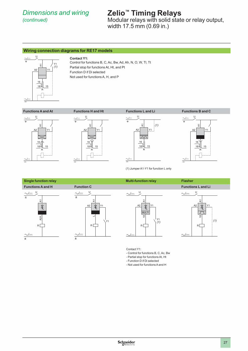
Wiring connection diagrams for RE17 models
A2 Y1
A1
U
+
–
16
15R
18
Y1(1)
Contact Y1:Control for functions B, C, Ac, Bw, Ad, Ah, N, O, W, Tl, TtPartial stop for functions At, Ht, and PtFunction D if Di selectedNot used for functions A, H, and P
Functions A and At Functions H and Ht Functions L and Li Functions B and C
A2 Y1
A1
U
+
–
16
15R
18
A2 Y1
A1
U
+
–
16
15R
18
A2 Y1
A1
U
+
–
16
15R
18
(1)
A2 Y1
A1
U
+
–
16
15R
18
(1) Jumper A1-Y1 for function L only
Single function relay Multi-function relay Flasher
Functions A and H Function C Functions L and Li
R
A2/
LA
1
U
±
±
R
LA1
U
±
±
A2 Y1
Y1
R
A2 Y1
18A
1
U
Y1(1)
/
/
(1)
R
A2 Y1
18A
1
U
Contact Y1:- Control for functions B, C, Ac, Bw- Partial stop for functions At, Ht- Function D if Di selected- Not used for functions A and H
Zelio™ Timing RelaysModular relays with solid state or relay output, width 17.5 mm (0.69 in.)
28
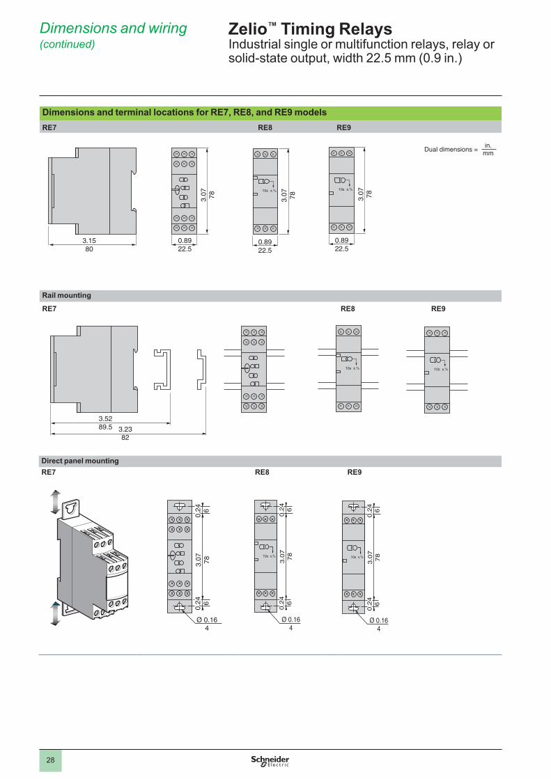
Dimensions and terminal locations for RE7, RE8, and RE9 modelsRE7 RE8 RE9
0.8922.5
3.1580
3.07 78
0.8922.5
3.1580
3.07 78
0.8922.5
3.1580
3.07 78
Rail mounting
RE7 RE8 RE9
3.5289.5 3.23
82
3.5289.5 3.23
82
3.5289.5 3.23
82
Direct panel mountingRE7 RE8 RE9
Ø 0.164
0.24 6
0.24 6
3.07 78
Ø 0.164
0.2
46
3.0
778
0.2
46
Ø 0.164
0.2
46
3.0
778
0.2
46
Zelio™ Timing RelaysIndustrial single or multifunction relays, relay or solid-state output, width 22.5 mm (0.9 in.)
Dual dimensions = in.mm
Dimensions and wiring (continued)
29
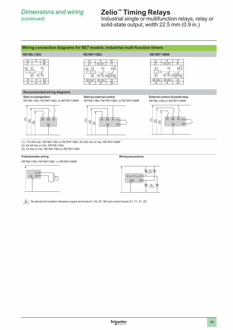
Dimensions and wiring (continued)
Wiring connection diagrams for RE7 models: Industrial multi-function timersRE7ML11BU RE7MY13BU RE7MY13MW
A1 15 B1Z1 B2
Y1X1 Z218 16 A2
1815B
1
A1
A2
16
A1 15 B125 (21)Z1 Y1
26 (22)28 (24) Z218 16 A2
1815B
1
A1
A2
16 28 (24)
25 (21)
26 (22)
A1 15 Y125 (21)Z1 X1
26 (22)28 (24) Z218 16 A2
1815A
1A
2
16 2825
26 (24)
(21)
(22)
Recommended wiring diagramsStart on energizationRE7ML11BU, RE7MY13BU, or RE7MY13MW
(3) (2
)
(1)
B1 A1B2
A2
Start by external controlRE7ML11BU, RE7MY13BU, or RE7MY13MW
B1 A1B2
A2
Y1
Z2(3)(2)(1)
External control of partial stopRE7ML11BU or RE7MY13MW
B1 A1B2
A2
X1
Z2(3)(2)(1)
(1) 110-240 Vac: RE7ML11BU or RE7MY13BU; 24-240 Vdc or Vac: RE7MY13MW(2) 42-48 Vac or Vdc: RE7ML11BU(3) 24 Vac or Vdc: RE7ML11BU or RE7MY13BU
Potentiometer wiring
RE7ML11BU, RE7MY13BU, or RE7MY13MW
Wiring precautions
X1 or Y1 or Z1Z2A2�
No electrical insulation between supply terminals A1, A2, B1, B2 and control inputs X1, Y1, Z1, Z2.
Zelio™ Timing RelaysIndustrial single or multifunction relays, relay or solid-state output, width 22.5 mm (0.9 in.)
Z1Z2A2

30
Dimensions and wiring (continued)
Wiring connection diagrams for RE8 models: Industrial single-function relay output timersRE8TA, CL RE8RA RE8RB
A1 15 B1
18 16 A2
1815B
1
A2
A1
16
A1 15 B1
18 16 A2
1815B
1
A2
A1
16
A1 15 B1
18 16 A2
1815B
1
A2
A1
16
Recommended wiring diagramsRE8TA, RB, CL
(2)
(1
)
B1 A2
A1
RE8RA
A1
A2
Y1
(4)
(3)
+
–
(1) 110-240 Vac (2) 24 Vdc or Vac (3) 24 Vdc (4) 24 Vac or 110-240 Vac
RE8TPE RE8PD RE8PT RE8YA RE8YG
A1 15 B1
18 16 A2
1815
16
B1
A2
A1
A1 15 Y1
18 16 A2
1815A
2A
1
16
A1 15 B1
18 16 A2
1815
16
B1
A2
A1
A1 15 25
28 16 A2
1615A
2A
1
2825
A1 15 B1
18 16 A2
1815B
1A
2A
1
16
Recommended wiring diagrams - interval timersRE8PE
(2)
(1
)
B1 A2
A1
RE8PD
A1
A2
Y1
(4)
(3)
+
–
(1) 110-240 Vac (2) 24 Vdc or Vac (3) 24 Vdc (4) 24 Vac or 110-240 Vac
Recommended wiring diagrams - timers for star-delta startersRE8YG, RE8YA
– KM2 – KM3 – KM1
U1
V1
W1
U2
V2
W2
– Q1
L1 L2 L3
– Rth
Y
RE8YG
– KM3 – KM2 – K1T(1)
– KM1
Y
A1A2
A1A2
A1A2
A1A2
– KM3
– KM2
– KM1
– S2
– KM1
– K1T (1)16 15
– KM1
– KM2
– S1
– FU1
– Rth
L
(1) K1T: RE8YGp1ppTQ
RE8YA
– KM2 – KM3 – K1T(1)
– KM1
Y
A1A2
A1A2
A1A2
A1A2
– KM3
– KM2
– KM1
– S2
– KM1
– K1T– K1T
1516
2528
– S1
– FU1
– Rth
L
(1) K1T: RE8YA32ppTQ
NOTE: Correct operation of the star-delta starter associated with the RE8YG is only possible if the wiring diagram is strictly followed.
Zelio™ Timing RelaysIndustrial single or multifunction relays, relay or solid-state output, width 22.5 mm (0.9 in.)
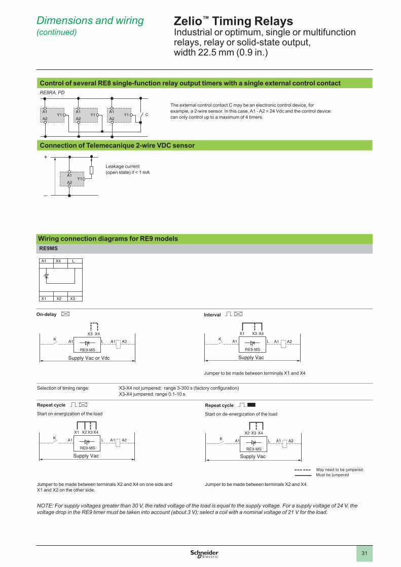
31
Control of several RE8 single-function relay output timers with a single external control contactRE8RA, PD
Y1A2
Y1A2
Y1A2
A1A1 A1C
The external control contact C may be an electronic control device, for example, a 2-wire sensor. In this case, A1 - A2 = 24 Vdc and the control device can only control up to a maximum of 4 timers.
Connection of Telemecanique 2-wire VDC sensor
Y1
–
+
A1
A2
Leakage current (open state) if < 1 mA
Wiring connection diagrams for RE9 modelsRE9MS
A1 L
X1 X3X2
X4
On-delay
A2L A1A1KX3 X4
RE9-MS
Supply Vac or Vdc
Interval
A2L A1A1KX1 X3 X4
RE9-MS
Supply Vac
Jumper to be made between terminals X1 and X4
Selection of timing range: X3-X4 not jumpered: range 3-300 s (factory configuration)X3-X4 jumpered: range 0.1-10 s
Repeat cycle
Start on energization of the load
A2L A1A1KX2 X3X1 X4
RE9-MS
Supply Vac
Repeat cycle
Start on de-energization of the load
A2L A1A1KX2 X3 X4
RE9-MS
Supply Vac
Jumper to be made between terminals X2 and X4 on one side and X1 and X2 on the other side.
Jumper to be made between terminals X2 and X4.
NOTE: For supply voltages greater than 30 V, the rated voltage of the load is equal to the supply voltage. For a supply voltage of 24 V, the voltage drop in the RE9 timer must be taken into account (about 3 V); select a coil with a nominal voltage of 21 V for the load.
Zelio™ Timing RelaysIndustrial or optimum, single or multifunction relays, relay or solid-state output, width 22.5 mm (0.9 in.)
Dimensions and wiring (continued)
May need to be jumpered.Must be jumpered
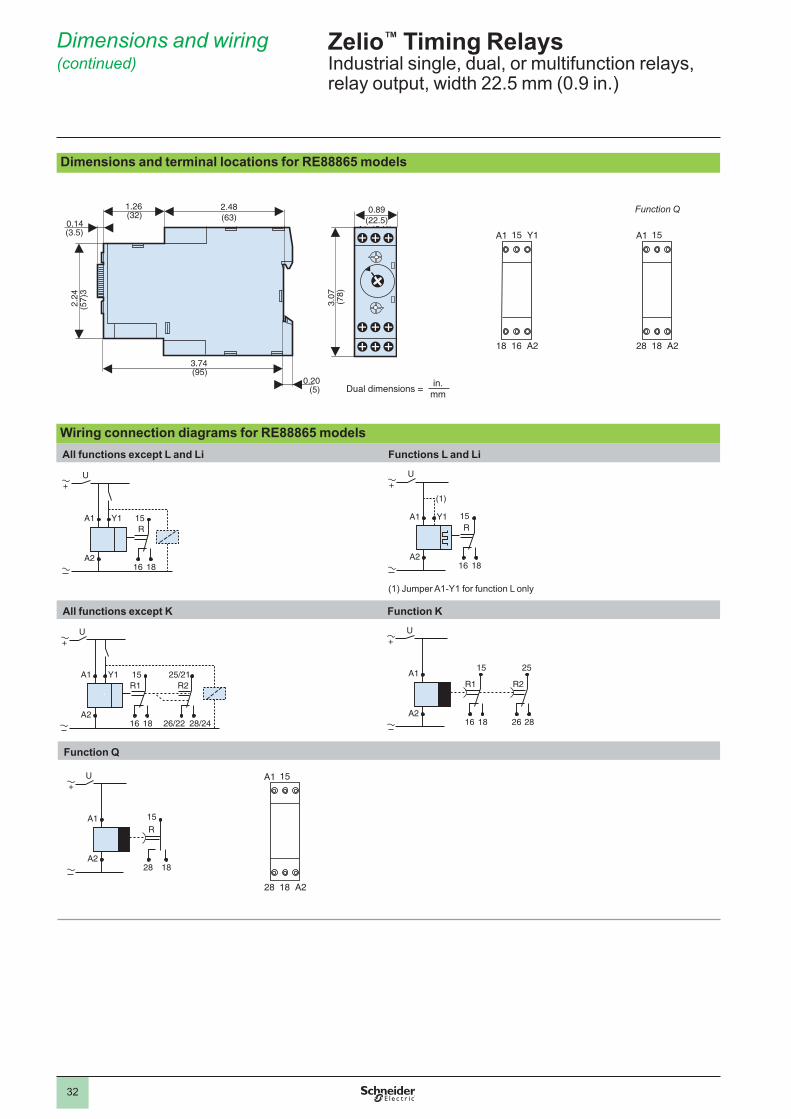
32
Dimensions and terminal locations for RE88865 models
Wiring connection diagrams for RE88865 modelsAll functions except L and Li Functions L and Li
U
A1R
15
A21816
Y1
+U
A1R
15
(1)
A21816
Y1
+
(1) Jumper A1-Y1 for function L only
All functions except K Function K
U
A1R1 R215
A21816
25/21
28/2426/22
Y1
+U
A1
A2
R1 R2
15
1816
25
2826
+
Function Q
U
A1R
15
A21828
+
A1 15
28 18 A2
Zelio™ Timing RelaysIndustrial single, dual, or multifunction relays, relay output, width 22.5 mm (0.9 in.)
Dimensions and wiring (continued)
A1 15 Y1
18 16 A2
1.26(32)
0.14(3.5)
3.74(95)
0.20(5)
2.24
(57)
3
3.07
(78)
2.48(63)
0.89(22.5)
A1 15 Y1
18 16 A2
Dual dimensions = in.mm
A1 15
28 18 A2
Function Q
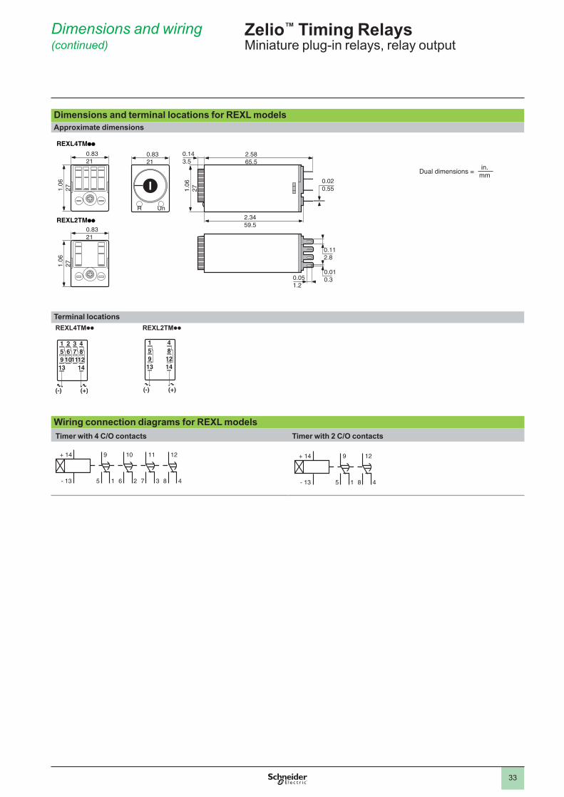
33
Dimensions and terminal locations for REXL modelsApproximate dimensions
REXL4TMpp
1.06
27
0.8321
1.06
27
0.8321
REXL2TMpp
R Un
0.8321
2.5865.5
0.143.5
1.06
27
2.3459.5
0.020.55
0.112.8
0.010.30.05
1.2
Terminal locationsREXL4TMpp
15913
(-)
26
10
37
11
481214
(+)
REXL2TMpp
15913
(-)
481214
(+)
Wiring connection diagrams for REXL modelsTimer with 4 C/O contacts Timer with 2 C/O contacts
- 13
9
5 1
+ 14
6
10
2
11
7 3
12
8 4 - 13
9
5 1
+ 14
8
12
4
Zelio™ Timing RelaysMiniature plug-in relays, relay output
Dual dimensions = in.mm
Dimensions and wiring (continued)
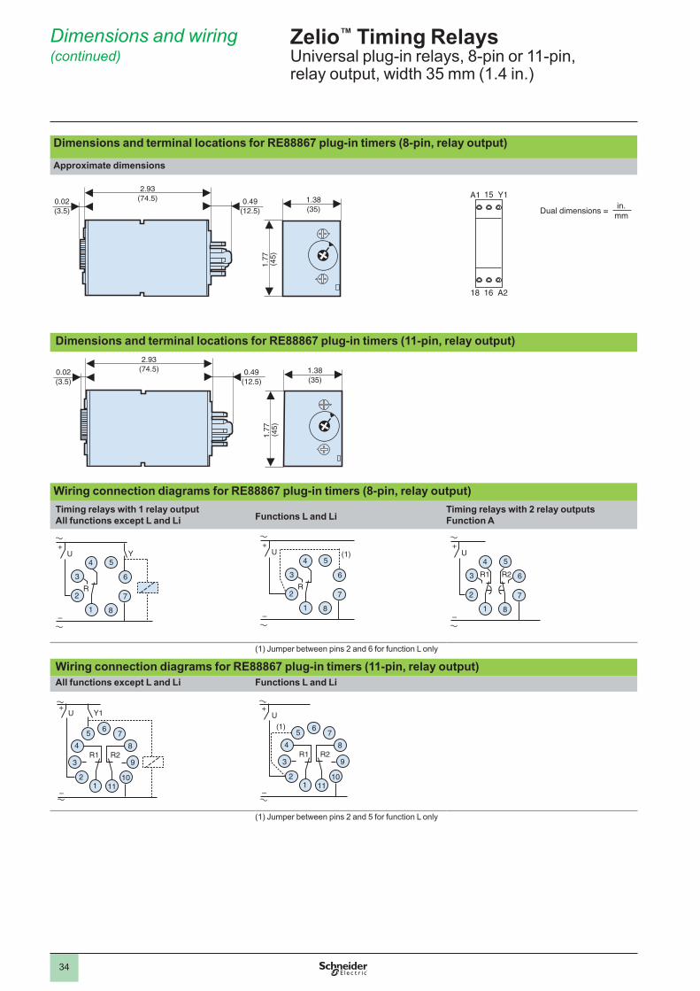
34
Dimensions and terminal locations for RE88867 plug-in timers (8-pin, relay output)
Approximate dimensions
1.77
(45)
0.02(3.5)
0.49(12.5)
2.93(74.5) 1.38
(35)
A1 15 Y1
18 16 A2
Dimensions and terminal locations for RE88867 plug-in timers (11-pin, relay output)
1.77
(45)
0.02(3.5)
0.49(12.5)
2.93(74.5) 1.38
(35)
Wiring connection diagrams for RE88867 plug-in timers (8-pin, relay output)Timing relays with 1 relay outputAll functions except L and Li Functions L and Li
Timing relays with 2 relay outputsFunction A
U4
R
+
–
5
6
7
81
2
3
Y U (1)4
R
+
–
5
6
7
81
2
3
U4
R1 R2
+
–
5
6
7
81
2
3
(1) Jumper between pins 2 and 6 for function L only
Wiring connection diagrams for RE88867 plug-in timers (11-pin, relay output)All functions except L and Li Functions L and Li
U
4R1
Y1
R2
+
–
56
7
8
9
10111
2
3
U
(1)
4R1 R2
+
–
56
7
8
9
10111
2
3
(1) Jumper between pins 2 and 5 for function L only
Zelio™ Timing RelaysUniversal plug-in relays, 8-pin or 11-pin, relay output, width 35 mm (1.4 in.)
Dimensions and wiring (continued)
Dual dimensions = in.mm
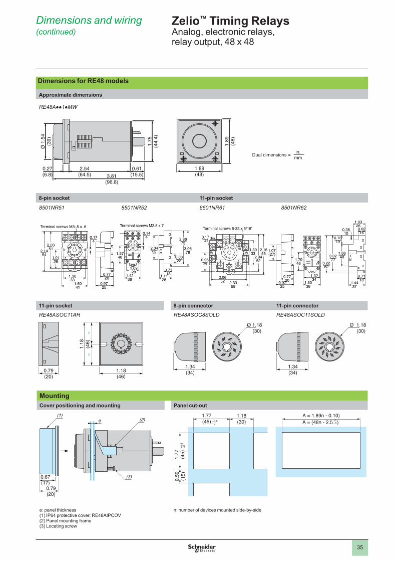
35
Dimensions and wiring (continued)
Dimensions for RE48 models
Approximate dimensions
RE48App1pMW
1.89
(48)
1.75
(44.
4)
Ø 1
.54
(39)
0.27(6.8)
2.54(64.5)
0.61(15.5)
1.89(48)3.81
(96.8)
8-pin socket 11-pin socket
8501NR51 8501NR52 8501NR61 8501NR62
0.7720
0.9725
Terminal screws M3 .5 x .6
2.1454
2.0351
1.3033
1.6041
0.174
1.0126
1.0928
1.4236
3.0678
2.8673
0.8822
0.7118
1.1128
0.144
1.5740
2.0452
Terminal screws M3.5 x 7
1.07(27)
0.7720
0.9725
Terminal screws 6-32 x 5/16"
dia.0.174
2.0652 2.33
59
0.9624
1.3033
2.1655
2.0452
3.2282
3.0277
1.8848
0.7619
0.3810
0.7118
1.4437
0.6216
1.0326
1.3234
1.5038
1.7946
11-pin socket 8-pin connector 11-pin connectorRE48ASOC11AR RE48ASOC8SOLD RE48ASOC11SOLD
==
1.18
(46)
1.18(46)
0.79(20)
Ø 1.18 (30)
1.34(34)
Ø 1.18 (30)
1.34(34)
MountingCover positioning and mounting Panel cut-out
e (2)
(3)0.67(17)
0.79(20)
(1) 1.77(45)
1.18(30)
1.77
(45)
0.59
(15)
A = (48n - 2.5 )A = 1.89n - 0.10)
e: panel thickness(1) IP64 protective cover: RE48AIPCOV(2) Panel mounting frame(3) Locating screw
n: number of devices mounted side-by-side
Zelio™ Timing RelaysAnalog, electronic relays, relay output, 48 x 48
Dual dimensions = in.mm

36
Wiring connection diagrams for RE48 panel-mount timersRE48ATM12MW
1
U
R2
3
4 5
8
7
6
RE48ACV12MW
6 75 84
93
111
102
U
R
Gate
RE48AML12MW
6 75 84
93
111
102
U
R
Gate
Reset
Start
RE48AMH13MW
1
U
R1 R22
3
4 5
8
7
6
Zelio™ Timing RelaysAnalog, electronic relays, relay output, 48 x 48
Dimensions and wiring (continued)


The information and dimensions in this catalog are provided for the convenience of our customers. While this information is believed to be accurate, Schneider Electric reserves the right to make updates and changes without prior notification and assumes no liability for any errors or omissions.
Zelio, Schneider Electric and logo, and “Make the most of your energy” are trademarks or registered trademarks of Schneider Electric or its affiliates in the United States and other countries. Other trademarks used herein are the property of their respective owners.
Design: Schneider ElectricPhotos: Schneider Electric
© 2010–2013 Schneider Electric. All rights reserved. 7/20139050CT0001R04/13
www.schneider-electric.comSchneider Electric USA, Inc.8001 Knightdale Blvd. Knightdale, NC 27545
USA Customer Care CenterTel: 888-778-2733
Schneider Electric Canada5985 McLaughlin Rd.Missassauga, Ontario, Canada L5R 1B8
Canada Customer Care CenterTel: 800-565-6699