Selection guide Zelio Time - timing relays - Trinet · PDF fileSelection guide Zelio Time -...
66
0249Q-EN_Ver1.0.fm/2 Schneider Electric Selection guide Zelio Time - timing relays 0 Applications These timing relays enable simple automation cycles to be set up using wired logic. They can also be used to complement the functions of PLCs. Output Solid state Timing relays with solid state output reduce the amount of wiring required (wired in series). The durability of these timing relays is independent of the number of operating cycles. Relay Relay outputs provide complete isolation between the supply and outut circuits. It is possible to have several output circuits. Type Modular Industrial Modular Industrial Timing ranges 7 ranges : 1 s, 10 s, 1 min, 10 min, 1 h, 10 h, 100 h 1 or 2 ranges, depending on model : 10 s, 30 s, 300 s, 60 min 7 ranges : 1 s, 10 s, 1 min, 10 min, 1 h, 10 h, 100 h Depending on model : 4 ranges : 0.6 s, 2.5 s, 20 s, 160 s 7 ranges : 1 s, 10 s, 1 min, 10 min, 1 h, 10 h, 100 h 7 ranges : 1 s, 3 s, 10 s, 30 s, 100 s, 300 s, 10 min 10 ranges : 1 s, 3 s, 10 s, 30 s, 100 s, 300 s, 30 min, 300 min, 30 h, 300 h Relay type RE 88 826 0// RE9 RE 88 826 1// RE 88 826 503 RE 88 865 /// RE7 Pages 28501/4 and 28501/5 28503/2 28502/4 and 28502/5 28509/4 to 28510/5 and 28504/2 to 28505/ 3
Transcript of Selection guide Zelio Time - timing relays - Trinet · PDF fileSelection guide Zelio Time -...

0249Q-EN_Ver1.0.fm/2 Schneider Electric
Selection guide Zelio Time - timing relays 0
Applications These timing relays enable simple automation cycles to be set up using wired logic.They can also be used to complement the functions of PLCs.
Output Solid stateTiming relays with solid state output reduce the amount of wiring required (wired in series). The durability of these timing relays is independent of the number of operating cycles.
RelayRelay outputs provide complete isolation between the supply and outut circuits.It is possible to have several output circuits.
Type Modular Industrial Modular Industrial
Timing ranges 7 ranges :1 s, 10 s, 1 min, 10 min, 1 h, 10 h, 100 h
1 or 2 ranges,depending on model :10 s, 30 s, 300 s, 60 min
7 ranges :1 s, 10 s, 1 min, 10 min, 1 h, 10 h, 100 h
Depending on model :4 ranges :0.6 s, 2.5 s, 20 s, 160 s7 ranges :1 s, 10 s, 1 min, 10 min, 1 h, 10 h, 100 h7 ranges :1 s, 3 s, 10 s, 30 s, 100 s, 300 s, 10 min10 ranges :1 s, 3 s, 10 s, 30 s, 100 s, 300 s, 30 min, 300 min, 30 h, 300 h
Relay type RE 88 826 0 RE9 RE 88 826 1RE 88 826 503
RE 88 865
RE7
Pages 28501/4 and 28501/5 28503/2 28502/4 and 28502/5 28509/4 to 28510/5and 28504/2 to 28505/3

0249Q-EN_Ver1.0.fm/3Schneider Electric
Selection guide (continued) Zelio Time - timing relays 0
These timing relays enable simple automation cycles to be set up using wired logic.They can also be used to complement the functions of PLCs.
RelayRelay outputs provide complete isolation between the supply and output circuits.It is possible to have several output circuits.
Optimum Plug-in Panel-mounted
Universal Miniature Analogue Digital Electromechanical
1 range,depending on model :0.5 s, 3 s, 10 s, 30 s, 300 s, 30 min
7 ranges :1 s, 10 s, 1 min, 10 min, 1 h, 10 h, 100 h
7 ranges :1 s, 10 s, 1 min, 10 min, 1 h, 10 h, 100 h
Depending on model :6 ranges :1 s, 10 s, 1 min, 10 min, 1 h, 10 h8 ranges :1 s, 10 s, 1 min, 4 min, 10 min, 1 h, 10 h, 60 h
Depending on model :7 ranges :99.99 s, 999.99 s, 99 min 59 s, 99.99 min, 999.9 min, 99 h 59 min, 999.9 h11 ranges :99.99 s, 999.99 s, 9999 s, 99 min 59 s, 99.99 min, 999.9 min, 9999 min, 99 h 59 min, 99,99 h, 999.9 h, 9999 h
Depending on model :3 ranges :6 s, 60 s, 12 min3 ranges :6 min, 60 min, 12 h
RE8 RE 88 867 RE 88 896 20 RE 88 875
RE 88 896
RE 88 857 RE 88 226
28507/2 to 28508/3 28511/4 to 28512/5 28513/3 28516/3, 28515/3 28517/5, 28518/5and 28519/3
28520/3

28501-EN_Ver2.0.fm/2 Schneider Electric
Characteristics Zelio Time - timing relays 0
Modular relays, solid state outputwidth 17.5 mm
Timing characteristicsRepeat accuracy(with constant parameters)
Conforming to IEC 1812-1 ± 0.5 %
Drift Temperature ± 0.05 % / °C
Voltage ± 0.2 % / V
Setting accuracy at full scale Conforming to IEC 1812-1 ± 10 % at 25 °CMinimum duration ofcontrol impulse
Typical ms 50
Maximum reset timeby de-energisation
Typical ms 350
Immunity timeto microbreaks
Typical ms > 10
Supply characteristicsMultivoltage supply Depending on version, see pages 24501/4 and 24501/5Frequency Hz 50/60
Operating range 85…110 % Un
On-load factor 100 %Maximum powerconsumption
Dependingon model
c 24 V W 0.6
c 240 V W 1.5
a 240 V VA 32
Output characteristicsOutput type Solid stateBreaking capacity A a/c 0.7 at 20° C (0.5 A UL)
Derating mA 5 / °C
Maximum permissible current A 20 10 ms Minimum breaking current mA 10
Leakage current mA < 5
Maximum switching voltage V a/c 250Typical voltage drop at terminals 3-wire 4V - 2-wire 8V
Electrical life 108 operations
Mechanical life 108 operationsDielectric strength conforming to IEC 664, IEC 255-5 kV 2.5 at 1 mA / 1 min
Display characteristicsState indicationby 1 LED
Green Operating status indication:Pulsing : relay energised, no timing in progress
(except Di-D and Li-L)Flashing : timing in progress
On steady : relay energised, no timing in progress
Input characteristicsInput type V Volt-free contact (no potential)
Control possible by 3-wire sensor with PNP output, maximum residual voltage : 0.4 V whatever the supply voltage of the timer
References :pages 28501/4 and 28501/5
Dimensions :page 28501/4
Schemes :page 28501/5

28501-EN_Ver2.0.fm/3Schneider Electric
Characteristics (continued) Zelio Time - timing relays 0
Modular relays, solid state outputwidth 17.5 mm
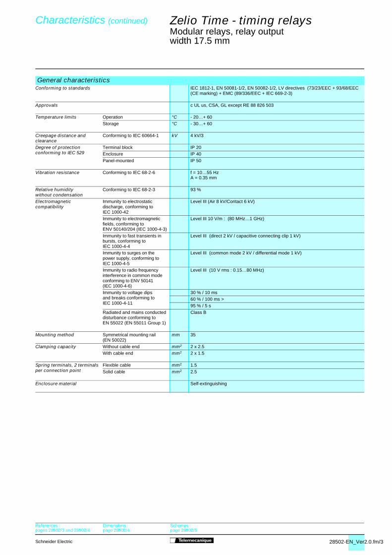
General characteristicsConforming to standards IEC 1812-1, EN 50081-1/2, EN 50082-1/2, LV directives (73/23/EEC + 93/68/EEC
(CE marking) + EMC (89/336/EEC + IEC 669-2-3)Approvals c UL us, CSA
Temperature limits Operation °C - 20…+ 60
Storage °C - 30…+ 60
Creepage distanceand clearance
Conforming to IEC 60664-1 kV 4 kV/3
Degree of protectionconforming to IEC 529
Terminal block IP 20
Enclosure IP 40Panel-mounted IP 50
Vibration resistance Conforming to IEC 68-2-6 f = 10…55 HzA = 0.35 mm
Relative humiditywithout condensation
Conforming to IEC 68-2-3 93 %
Electromagneticcompatibility
Immunity to electrostatic discharge, conforming toIEC 1000-42
Level III (Air 8 kV/Contact 6 kV)
Immunity to electromagnetic fields, conforming toENV 50140/204 (IEC 1000-4-3)
Level III 10 V/m : (80 MHz…1 GHz)
Immunity to fast transients in bursts, conforming toIEC 1000-4-4
Level III (direct 2 kV / capacitive connecting clip 1 kV)
Immunity to surgeson the power supplyconforming to IEC 1000-4-5
Level III (common mode 2 kV / differential mode 1 kV)
Immunity to radio frequency interference in common modeconforming to ENV 50141(IEC 1000-4-6)
Level III (10 V rms : 0.15…80 MHz)
Immunity to voltage dips and breaks conforming toIEC 1000-4-11
30 % / 10 ms60 % / 100 ms >
95 % / 5 s
Radiated and mains conducted disturbance conforming toEN 55022 (EN 55011 Group 1)
Class B
Mounting method Symmetrical mounting rail (EN 50022)
mm 35
Clamping capacity Without cable end mm2 2 x 2.5
With cable end mm2 2 x 1.5
Spring terminals, 2 terminalsper connection point
Flexible cable mm2 1.5
Solid cable mm2 2.5
Enclosure material Self-extinguishing
References :pages 28501/4 and 28501/5
Dimensions :page 28501/4
Schemes :page 28501/5

28501-EN_Ver2.0.fm/4 Schneider Electric
References,dimensions,schemes
Zelio Time - timing relays 0
Modular relays, solid state outputwidth 17.5 mm
Solid state outputb Multifunction or single functionb Multi-range (7 switchable ranges)b Multivoltageb Solid state output : 0.7 A - 250 V (0.5 A UL)b Screw terminals b State indication by 1 LED
Function diagramsFunction A Function H Function Li
Delay on energisation
Timing on energisationPulse-on energisation
Asymmetrical recycler Pulse start
Function B Function L Function DiTiming on impulse, one shot
Asymmetrical recycler Start after pause
Symmetrical flasher, start with output in operating position
References
Connection Screw terminals p pFunctions Multifunction Single function
A - At - B - C - H - Ht - Di - D - Ac - Bw ATiming ranges 7 ranges 1 s - 10 s - 1 min - 10 min - 1 h - 10 h - 100 h
Rated current 0.7 A 0.7 A
Voltages 24…240 V a 50/60 Hz RE 88 826 004 –24…240 V a/c 50/60 Hz – RE 88 826 014
Weight (kg) 0.060 0.060
Dimensions and connection schemesDimensions
U
RT T
R
U
T1R
U
T2
U
C
R∞ T
T1R
T2
U U
RT T
5608
47
560
848
5,5
81
17,5
60
45
443,5
Characteristics :pages 28501/2 and 28501/3
Schemes :page 28501/5

28501-EN_Ver2.0.fm/5Schneider Electric
0
Function C Function At Function Ht Function D Function BwOff-delay, with control contact
Timing on energisationwith memory
Delay on energisationwith memory
Symmetrical flasher, start with output in rest position
Pulse output (adjustable)
Function AcTiming after closing/opening of control contact
p pSingle function Dual function
H Li - L1 s - 10 s - 1 min - 10 min - 1 h - 10 h - 100 h
0.7 A 0.7 A
RE 88 826 044 RE 88 826 054– –
0.060 0.060
Connection schemesFunctions A, H Function U Functions L, Li
(1) Link A2-Y1 for function L only.
U
C
R∞ T
U
C
Rt1 t2
T = t1+t2t1
R
C
U
t2T = t1+t2
U
T TR
U
C
RT T
U
C
RT T
560
848
5608
49
U
R
A1
A2
±
±
U
R
A1
18
MULTI
A2 Y1
Y1
U
R
A1
18
A2 Y1
(1)
Characteristics :pages 28501/2 and 28501/3
Dimensions :page 28501/4

28465_Ver3.00-EN.fm/2 Schneider Electric
References : page 28503/2
Dimensions:page 28503/2
Schemes : page 28503/3
Zelio Time - timing relaysIndustrial relays, solid state outputwidth 22.5 mm
Presentation
The RE9 range of relays is designed for simple, repetitive applications with short and intensive cycles because theirsolid state output provides very high electrical durability.
Each relay has a single timing range.
Each relay has a wide voltage range from 24 to 240 V.The range comprises 9 references with 3 model types :- RE9-TA : function A- RE9-RA : function C,- RE9-MS : multifunction A, H, L, Li.
These products have a transparent, hinged flap on their front face to avoid any accidental alteration of the settings. Thisflap can be directly sealed.
Environment
Conforming to standards IEC 61812-1, EN 61812-1
Approvals CSA, GL pending, UL
marking Zelio Time timing relays conform to European regulations relating to marking
Ambient air temperature around the device
Storage °C - 40…+ 85Operation °C - 20…+ 60
Permissible relative humidity range Conforming to IEC 60721-3-3 15…85 % Environmental class 3K3
Vibration resistance Conforming to IEC 6068-2-6, 10 to 55 Hz a = 0.35 ms
Shock resistance Conforming to IEC 6068-2-27 15 gn - 11 ms
Degree of protection Casing IP 50Terminals IP 20
Degree of pollution Conforming to IEC 60664-1 3
Overvoltage category Conforming to IEC 60664-1 III
Rated insulation voltage Conforming to IEC V 250Conforming to CSA V 300
Test voltage for insulation tests Dielectric test kV 2.5 Shock wave kV 4.8
Voltage limits Power supply circuit 0.85…1.1 Uc
Frequency limits Power supply circuit Hz 50/60 ± 5 %
Disconnection value Power supply circuit > 0.1 Uc
Mounting position In relation to normal vertical mounting plane
Any positionwithout derating
Connection Maximum c.s.a. Flexible cable without cable end mm2 2 x 2.5 Flexible cable with cable end mm2 2 x 1.5
Tightening torque N.m 0.6…1.1
Immunity to electromagnetic interference (EMC) (Application class 2 conforming to EN 61812-1)
Electrostatic discharge Conforming to IEC 61000-2-6 Level 3 (6 kV contact, 8 kV air)
Electromagnetic fields Conforming to IEC 61000-4-3 Level 3 (10 V/m)
Fast transients Conforming to IEC 61000-4-4 Level 3 (2 kV)
Shock waves Conforming to IEC 61000-4-5 Level 3 (2 kV)
Radiated and conducted CISPR11 Group 1 class Aemissions CISPR22 Class A
5608
53General characteristics

28465_Ver3.00-EN.fm/3Schneider Electric
Zelio Time - timing relaysIndustrial relays, solid state outputwidth 22.5 mm
Timing relay type RE9-TA RE9-RA RE9-MSOn-delay Off-delay Multifunction
Supply characteristics
Supply voltage V 24…240 24…240 24…240. See page28467/2
Voltage limits Power supply circuit 0.85…1.1 Un
Frequency Hz 50…60 ± 5 %
Control contact Mechanical only In series Between Y2 and A2 In series
Max. length of connecting cable From contact to RE9 m – 20 –
Control input consumption Input Y2 mA – 5 –
Timing characteristics
Setting accuracy < ± 20 %
Repeat accuracy < 1 %
Minimum reset time After the time delay period ms 100
Minimum switching time time ms – 40 –
Maximum immunity to microbreaks During the time delay period ms 100 2 70
After the time delay period ms 2 – 2
Temperature drift ≤ 0.1 % per degree centigrade
Switching characteristics (solid state type)
Maximum continuous current At ambient temperature : 20 °C A 0.7 (minimum 10 mA)
Maximum overload current VDE 0435 part. 303, 4.8.3/Class II A 15 for 10 ms
Maximum voltage drop Closed state V A 0.7 A : 3
Leakage current Open state mA ≤ 6 ≤ 1 ≤ 6
Maximum dissipated power W 2.5 4 2.5
Derating For temperature > 20 °C mA Without
Electrical durability In millions of operating cycles > 100
General characteristics (continued)
References : page 28503/2
Dimensions:page 28503/2
Schemes : page 28503/3

28503-EN_Ver3.0.fm/2 Schneider Electric
Functions,references,dimensions
Zelio Time - timing relays 0
Industrial relays, solid state outputwidth 22.5 mm
Output 1 C/O contact Function diagramsFunction A Function C Function H
Delay on energisation
Off-delay
Timing on energisation Pulse-on energisation
Function Di Function DSymmetrical flasher, start with output in operating position
Symmetrical flasher, start start with output in rest position
References
Functions A C A, H, D, DiVoltages c or a 24…240 V p – p (A)
a 24…240 V – p p (H, D, Di)Timing ranges 0.1 s…10 s RE9 TA11MW RE9 RA11MW7 RE9 MS21MW
0.3 s…30 s RE9 TA31MW RE9 RA31MW7 –3 s…300 s RE9 TA21MW RE9 RA21MW7 RE9 MS21MW40 s…60 min RE9 TA51MW RE9 RA51MW7 –
Weight (kg) 0.110 0.110 0.110
DimensionsRail mounting Screw fixing
t
Supply
Load
t
Supply
Control contact K
Loadt
Supply
Load
=t
=t
Supply
Control contact K
Load
=t
=t
Supply
Control contact K
Load
5608
54
5608
55
5608
55
89,5
82
78
80
66
78
Characteristics :pages 28465/2 and 28465/3
Schemes :page 28503/3

28503-EN_Ver3.0.fm/3Schneider Electric
Schemes Zelio Time - timing relays 0
Industrial relays, solid state outputwidth 22.5 mm
Terminal blocksRE9 TA RE9 RA RE9 MS
Recommended application schemesRE9 TA
The timing relay is placed in series, with the load whose de-energisation is to be delayed on one side and switch K on the other side. The mains supply may be a.c. or d.c. and the voltage may be between 24 V and 240 V. See function diagram on page opposite.
RE9 RA
The timing relay is placed in series with the load whose de-energisation is to be delayed. Switch K is connected to terminals Y2 and A2 of the timing relay, and terminal A2 is connected to the mains supply, as indicated in the diagram opposite. The device is operated from an a.c. mains supply whose voltage is between 24 V and 240 V. See function diagram on page opposite.
RE9 MSDelay on energisationFunction A
Pulse-on energisationFunction H Selection of the timing range
X3-X4 not linked : range 3 s…300 s(factory configuration)
X3-X4 linked : range 0.1 s…10 s
Link to be made between terminals X1 and X4
Symmetrical flasherStart with output in the rest positionFunction D
Symmetrical flasherStart with output in the operating positionFunction Di
Link to be made between terminals X2 and X4 on one side and between X1 and X2 on the other side
Link to be made between terminals X1 and X4
Note : For supply voltages greater than 30 V, the rated voltage of the load is equal to the supply voltage. For a supply voltage of 24 V, the voltage drop within the RE9 relay must be taken into account (about 3 V); a coil with a nominal voltage of 21 V must therefore be selected for the load.
A1 L A1 L
Y2 A2
A1 L
X1 X3X2
X4
LA1KRE9-TA
Supply a or c
Load
LA1
K A2Y2
RE9-RA
Supply a or c
Load
A2L A1A1KX3 X4
RE9-MS
Supply a or c
Load
A2L A1A1KX1 X3 X4
RE9-MS
Supply a
Load
A2L A1A1KX2 X3X1 X4
RE9-MS
Supply a
Load
A2L A1A1KX2 X3 X4
RE9-MS
Supply a
Load
Characteristics :pages 28465/2 and 28465/3
Dimensions :page 28503/2

28502-EN_Ver2.0.fm/2 Schneider Electric
Characteristics Zelio Time - timing relays 0
Modular relays, relay outputwidth 17.5 mm
Timing characteristicsRepeat accuracy(with constant parameters)
Conforming to IEC 1812-1 ± 0.5 %
Drift Temperature ± 0.05 % / °CVoltage ± 0.2 % / V
Setting accuracy at full scale Conforming to IEC 1812-1 ± 10 % at 25 °CMinimum duration ofcontrol impulse
Typical ms 30Typical under load ms 100
Maximum reset timeby de-energisation
Typical ms 100
Immunity timeto microbreaks
Typical ms > 10
Supply characteristicsMultivoltage supply Depending on version, see pages 28503/4 and 28503/5Frequency Hz 50/60Operating range 85…110 % of Un
On-load factor 100 %Maximumpower consumption
Dependingon model
c 24 V W 0.6
c 240 V W 1.5 a 240 V VA 32
Output characteristicsOutput type Relay, 1 C/O contact, AgNi (cadmium-free)
Breaking capacity a 2000 VA, c 80 WMaximum breaking current A a 8, c 8
Minimum breaking current mA 10 /c 5 V Maximum switching voltage V a/c 250Electrical life 105 operations 8 A 250 V resistive
Mechanical life 5 x 10⁶ operationsDielectric strength Conforming to IEC 1812-1 kV 2.5/1min/1 mA/50 HzImpulse voltage Conforming to IEC 664-1,
IEC 1812-1kV 5, wave 1.2/50 µs
Display characteristicsState indication by 1 LED Green Operating status indication
Pulsing : relay energised, no timing in progress (except Di-D and Li-L)
Flashing : timing in progress
On steady : relay energised, no timing in progress
Input characteristicsInput type V Volt-free contact (no potential)
Control possible by 3-wire sensor with PNP output, maximum residual voltage : 0.4 V whatever the supply voltage of the relay
References :pages 28502/3 and 28502/4
Dimensions :page 28502/4
Schemes :page 28502/5
28502-EN_Ver2.0.fm/3Schneider Electric
Characteristics (continued) Zelio Time - timing relays 0
Modular relays, relay outputwidth 17.5 mm
General characteristicsConforming to standards IEC 1812-1, EN 50081-1/2, EN 50082-1/2, LV directives (73/23/EEC + 93/68/EEC
(CE marking) + EMC (89/336/EEC + IEC 669-2-3)
Approvals c UL us, CSA, GL except RE 88 826 503
Temperature limits Operation °C - 20…+ 60 Storage °C - 30…+ 60
Creepage distance and clearance
Conforming to IEC 60664-1 kV 4 kV/3
Degree of protectionconforming to IEC 529
Terminal block IP 20Enclosure IP 40
Panel-mounted IP 50
Vibration resistance Conforming to IEC 68-2-6 f = 10…55 HzA = 0.35 mm
Relative humiditywithout condensation
Conforming to IEC 68-2-3 93 %
Electromagneticcompatibility
Immunity to electrostatic discharge, conforming toIEC 1000-42
Level III (Air 8 kV/Contact 6 kV)
Immunity to electromagnetic fields, conforming toENV 50140/204 (IEC 1000-4-3)
Level III 10 V/m : (80 MHz…1 GHz)
Immunity to fast transients in bursts, conforming toIEC 1000-4-4
Level III (direct 2 kV / capacitive connecting clip 1 kV)
Immunity to surges on thepower supply, conforming toIEC 1000-4-5
Level III (common mode 2 kV / differential mode 1 kV)
Immunity to radio frequency interference in common modeconforming to ENV 50141(IEC 1000-4-6)
Level III (10 V rms : 0.15…80 MHz)
Immunity to voltage dipsand breaks conforming toIEC 1000-4-11
30 % / 10 ms60 % / 100 ms >95 % / 5 s
Radiated and mains conducted disturbance conforming toEN 55022 (EN 55011 Group 1)
Class B
Mounting method Symmetrical mounting rail(EN 50022)
mm 35
Clamping capacity Without cable end mm2 2 x 2.5With cable end mm2 2 x 1.5
Spring terminals, 2 terminals per connection point
Flexible cable mm2 1.5
Solid cable mm2 2.5
Enclosure material Self-extinguishing
References :pages 28502/3 and 28502/4
Dimensions :page 28502/4
Schemes :page 28502/5

28502-EN_Ver2.0.fm/4 Schneider Electric
References,dimensions,schemes
Zelio Time - timing relays 0
Modular relays, relay outputwidth 17.5 mm
Output 1 C/O contactb Multifunction or single functionb Multi-range (7 switchable ranges)b Multivoltageb 1 relay output : 8 A - 250 V (10 A UL)b Screw or spring terminalsb State indication by 1 LEDb Option of supplying a load in parallelb 3-wire sensor control option
Function diagramsFunction A Function H Function Li
Delay on energisation
Timing on energisationPulse-on energisation
Asymmetrical recycler Pulse start
Function B Function L Function DiTiming on impulse, one shot
Asymmetrical recycler Start after pause
Symmetrical flasher, start with output in operating position
References
Connection Screw terminals p p pSpring terminals – – –
Functions Multifunction Dual function Single functionA - At - B - C - H - Ht - Di - D Ac - Bw
A - At B
Timing ranges 7 ranges 1 s - 10 s - 1 min - 10 min - 1 h - 10 h - 100 h
Rated current 8 A 8 A 8 AVoltages c 24 V / a 24…240 V RE 88 826 105 RE 88 826 115 RE 88 826 125
a/c 12…240 V – – –
Weight (kg) 0.060 0.060 0.060
Dimensions and connection schemesDimensions
U
RT T
R
U
T1R
U
T2
U
C
R∞ T
T1R
T2
U U
RT T
5608
50
5608
51
5608
51
5,5
81
17,5
60
45
443,5
Characteristics :pages 28502/2 and 28502/3
Schemes :page 28502/5

28502-EN_Ver2.0.fm/5Schneider Electric
0
Function C Function At Function Ht Function D Function BwOff-delay, with control contact
Timing on energisation with memory
Delay on energisation with memory
Symmetrical flasher, start with output in rest position
Pulse output (adjustable)
Function AcTiming after closing/opening of control contact
p p p p –– – – – pSingle function Dual function Dual function Multifunction Multifunction
C H - Ht Li - L A - At - B - C - H - Ht - Di -D - Ac - Bw
A - At - B - C - H - Ht - Di -D - Ac - Bw
1 s - 10 s - 1 min - 10 min - 1 h - 10 h - 100 h8 A 8 A 8 A 8 A 8 ARE 88 826 135 RE 88 826 145 RE 88 826 155 – –
– – – RE 88 826 103 RE 88 826 5030.060 0.060 0.060 0.060 0.060
ConnectionsAll functions except L and Li
Functions L and Li
(1) Link A1-Y1 for function L only.
U
C
R∞ T
U
C
Rt1 t2
T = t1+t2t1
R
C
U
t2T = t1+t2
U
T TR
U
C
RT T
U
C
RT T
5608
51
5608
51
5608
52
5608
50
5608
50
U
A1R
15
A21816
Y1
+U
A1R
15
(1)
A21516
Y1
+
Characteristics :pages 28502/2 and 28502/3
Dimensions :page 28502/4
28509_Ver1.00-EN.fm/2 Schneider Electric
Characteristics Zelio Time - timing relays 0
Industrial multifunction relays,relay output, width 22.5 mm
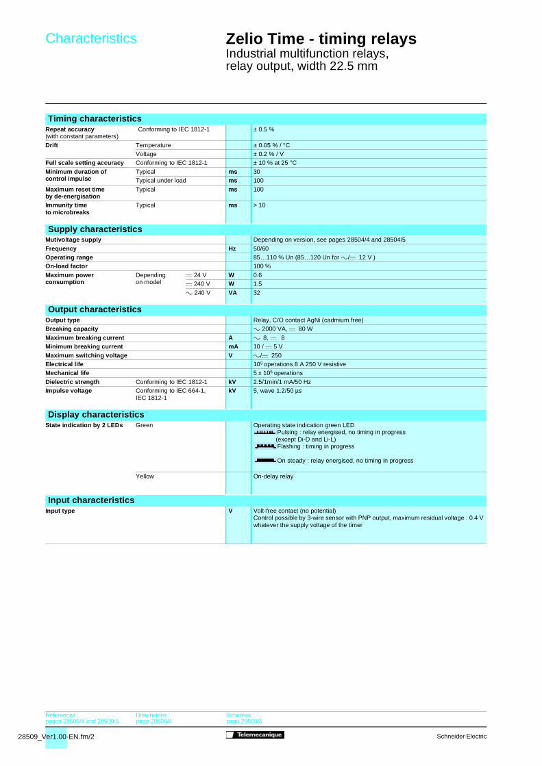
Timing characteristicsRepeat accuracy(with constant parameters)
Conforming to IEC 1812-1 ± 0.5 %
Drift Temperature ± 0.05 % / °CVoltage ± 0.2 % / V
Full scale setting accuracy Conforming to IEC 1812-1 ± 10 % at 25 °C
Minimum duration ofcontrol impulse
Typical ms 30Typical under load ms 100
Maximum reset timeby de-energisation
Typical ms 100
Immunity timeto microbreaks
Typical ms > 10
Supply characteristicsMutivoltage supply Depending on version, see pages 28504/4 and 28504/5
Frequency Hz 50/60Operating range 85…110 % Un (85…120 Un for a/c 12 V )On-load factor 100 %
Maximum powerconsumption
Dependingon model
c 24 V W 0.6c 240 V W 1.5
a 240 V VA 32
Output characteristicsOutput type Relay, C/O contact AgNi (cadmium free)Breaking capacity a 2000 VA, c 80 W
Maximum breaking current A a 8, c 8Minimum breaking current mA 10 / c 5 V
Maximum switching voltage V a/c 250Electrical life 105 operations 8 A 250 V resistiveMechanical life 5 x 10⁶ operations
Dielectric strength Conforming to IEC 1812-1 kV 2.5/1min/1 mA/50 HzImpulse voltage Conforming to IEC 664-1,
IEC 1812-1kV 5, wave 1.2/50 µs
Display characteristicsState indication by 2 LEDs Green Operating state indication green LED
Pulsing : relay energised, no timing in progress(except Di-D and Li-L)Flashing : timing in progress
On steady : relay energised, no timing in progress
Yellow On-delay relay
Input characteristicsInput type V Volt-free contact (no potential)
Control possible by 3-wire sensor with PNP output, maximum residual voltage : 0.4 Vwhatever the supply voltage of the timer
References :pages 28509/4 and 28509/5
Dimensions :page 28509/4
Schemes :page 28509/5
28509_Ver1.00-EN.fm/3Schneider Electric
Characteristics Zelio Time - timing relays 0
Industrial multifunction relays,relay output, width 22.5 mm
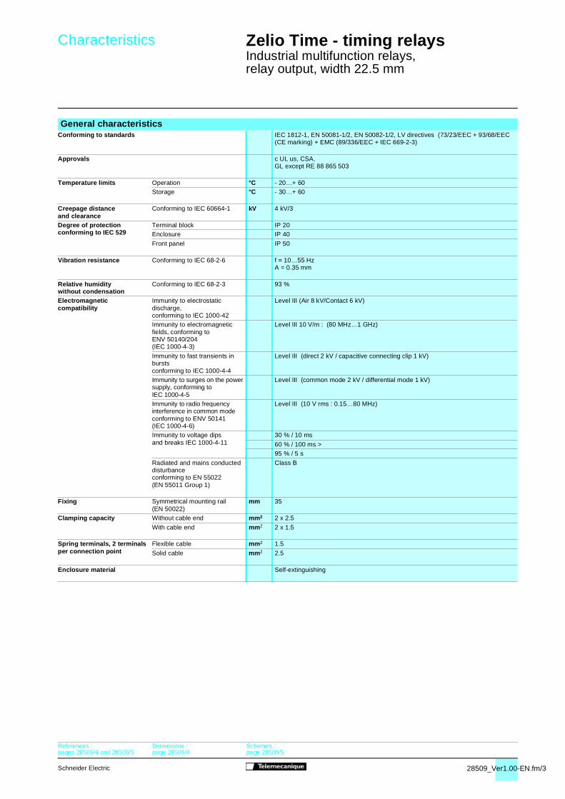
General characteristicsConforming to standards IEC 1812-1, EN 50081-1/2, EN 50082-1/2, LV directives (73/23/EEC + 93/68/EEC
(CE marking) + EMC (89/336/EEC + IEC 669-2-3)
Approvals c UL us, CSA,GL except RE 88 865 503
Temperature limits Operation °C - 20…+ 60Storage °C - 30…+ 60
Creepage distanceand clearance
Conforming to IEC 60664-1 kV 4 kV/3
Degree of protectionconforming to IEC 529
Terminal block IP 20Enclosure IP 40
Front panel IP 50
Vibration resistance Conforming to IEC 68-2-6 f = 10…55 HzA = 0.35 mm
Relative humiditywithout condensation
Conforming to IEC 68-2-3 93 %
Electromagneticcompatibility
Immunity to electrostaticdischarge,conforming to IEC 1000-42
Level III (Air 8 kV/Contact 6 kV)
Immunity to electromagneticfields, conforming toENV 50140/204(IEC 1000-4-3)
Level III 10 V/m : (80 MHz…1 GHz)
Immunity to fast transients inburstsconforming to IEC 1000-4-4
Level III (direct 2 kV / capacitive connecting clip 1 kV)
Immunity to surges on the powersupply, conforming toIEC 1000-4-5
Level III (common mode 2 kV / differential mode 1 kV)
Immunity to radio frequencyinterference in common modeconforming to ENV 50141(IEC 1000-4-6)
Level III (10 V rms : 0.15…80 MHz)
Immunity to voltage dipsand breaks IEC 1000-4-11
30 % / 10 ms
60 % / 100 ms >95 % / 5 s
Radiated and mains conducteddisturbanceconforming to EN 55022(EN 55011 Group 1)
Class B
Fixing Symmetrical mounting rail(EN 50022)
mm 35
Clamping capacity Without cable end mm2 2 x 2.5
With cable end mm2 2 x 1.5
Spring terminals, 2 terminalsper connection point
Flexible cable mm2 1.5
Solid cable mm2 2.5
Enclosure material Self-extinguishing
References :pages 28509/4 and 28509/5
Dimensions :page 28509/4
Schemes :page 28509/5

28509_Ver1.00-EN.fm/4 Schneider Electric
References,dimensions,schemes
Zelio Time - timing relays 0
Industrial multifunction relays,relay output, width 22.5 mm
Relay output, 1 C/O contactb Multifunction or single functionb Multi-range (7 switchable ranges)b Multivoltageb 1 relay output : 8 A - 250 V (10 A UL)b Screw or spring terminalsb State indication by 1 LEDb Option of supplying a load in parallelb 3-wire sensor control option
Function diagramsFunction A Function H Function Li
Delay on energisation Timing on energisation Asymmetrical recyclerPulse start
Function B Function L Function DiTiming on impulse, one shot Asymmetrical recycler
Start after pauseFlashing relayPulse start
References
Connection Screw terminals p p pSpring terminals – – –
Functions Multifunction Dual function Single functionA - At - B - C - H - Ht - Di - DAc - Bw
A - At B
Timing ranges 7 ranges 1 s - 10 s - 1 min - 10 min - 1 h - 10 h - 100 hSelectable interswitching time – – –
Rated current 8 A 8 A 8 AVoltages c 24 V / a 24…240 V RE 88 865 105 RE 88 865 115 RE 88 865 125
a/c 12 V – – –a/c 12…240 V – – –
a 230 / 380 V – – –Weight (kg) 0.090 0.090 0.090
Dimensions and connection schemesDimensions
U
RT T
R
U
T1R
U
T2
U
C
R∞ T
T1R
T2
U U
RT T
5611
71
5611
72
5611
72
32
3,5
95
5
57 78
63 22,5
A1 15 Y1
18 16 A2
Characteristics :pages 28509/2 and 28509/3
Schemes :page 28509/5

28509_Ver1.00-EN.fm/5Schneider Electric
0
Function C Function At Function Ht Function D Function BwOff-delay Timing on energisation
with memoryDelay on energisation withmemory
Flashing relayStart after pause
Pulse output (adjustable)
Function Ac Function QTiming after closing/openingof control contact
Star-delta starting
p p p p p p –– – – – – – pSingle function Dual function Dual function Single function Single function Multifunction Multifunction
C H - Ht Li - L Q Q A - At - B - C - H -Ht - Di - D - Ac - Bw
A - At - B - C - H -Ht - Di - D - Ac - Bw
1 s - 10 s - 1 min - 10 min - 1 h - 10 h - 100 h– – – 20 - 40 - 60 - 80 -
100 - 120 - 140 ms20 - 40 - 60 - 80 -100 - 120 - 140 ms
– –
8 A 8 A 8 A 8 A 8 A 8 A 8 ARE 88 865 135 RE 88 865 145 RE 88 865 155 RE 88 865 175 – – –
– – – – – – –– – – – – RE 88 865 103 RE 88 865 503– – – – RE 88 865 176 – –0.090 0.090 0.090 0.090 0.090 0.090 0.090
Connection schemesAll functions except L and Li Functions L and Li
(1) Link A1-Y1 for function L only.
Function Q
U
C
R∞ T
U
C
Rt1 t2
T = t1+t2t1
R
C
U
t2T = t1+t2
U
T TR
U
C
RT T
U
C
RT T
TR
U
Ti
5611
72
5611
72
5611
73
5611
72
5611
72
5611
71
5611
74
U
A1R
15
A21816
Y1
+U
A1R
15
(1)
A21516
Y1
+U
A1R
15
A21828
+
Characteristics :pages 28509/2 and 28509/3
Dimensions :page 28509/4

28510_Ver1.00-EN.fm/2 Schneider Electric
Characteristics Zelio Time - timing relays 0
Industrial multifunction relays,relay output, width 22.5 mm
Timing characteristicsRepeat accuracy(with constant parameters)
Conforming to IEC 1812-1 ± 0.5 %
Drift Temperature ± 0.05 % / °C
Voltage ± 0.2 % / VFull scale setting accuracy Conforming to IEC 1812-1 ± 10 % at 25 °C
Minimum duration of control impulse
Typical ms 30
Typical under load ms 100
Maximum reset time by de-energisation
Typical ms 100
Immunity timeto microbreaks
Typical ms > 10
Supply characteristicsMultivoltage supply Depending on version, see pages 28508/4 and 28508/5Frequency Hz 50/60
Operating range 85…110 % Un (85…120 Un for /12 V )
On-load factor 100 %
Maximum powerconsumption
Dependingon model
24 V W 0.6
240 V W 1.5
240 V VA 32
Output characteristicsOutput type Relay, C/O contacts, AgNi (cadmium-free)
Breaking capacity 2000 VA, 80 W
Maximum breaking current A 8, 8Minimum breaking current mA 10 / 5 V
Maximum switching voltage V /250
Electrical life 105 operations 8 A 250 V resistive
Mechanical life 5 x 10⁶ operations
Dielectric strength Conforming to IEC 1812-1 kV 2.5/1min/1 mA/50 Hz
Impulse voltage Conforming to IEC 664-1,IEC 1812-1
kV 5, wave 1.2/50 µs
Display characteristicsState indication by 2 LEDs Green Operating state indication green LED
Pulsing : relay energised, no timing in progress (except Di-D and Li-L)
Flashing : timing in progress
On steady : relay energised, no timing in progress
Yellow On-delay relay
Input characteristicsInput type V Volt-free contact (no potential)
Control possible by 3-wire sensor with PNP output, maximum residual voltage : 0.4 V whatever the supply voltage of the timer
References :pages 28510/4 and 28510/5
Dimensions :page 28510/4
Schemes :page 28510/5

28510_Ver1.00-EN.fm/3Schneider Electric
Characteristics Zelio Time - timing relays 0
Industrial multifunction relays,relay output, width 22.5 mm
General characteristicsConforming to standards IEC 1812-1, EN 50081-1/2, EN 50082-1/2, LV directives (73/23/EEC + 93/68/EEC
(CE marking) + EMC (89/336/EEC + IEC 669-2-3)
Approvals c UL us, CSAGL except RE 88 865 265
Temperature limits Operation °C - 20…+ 60
Storage °C - 30…+ 60
Creepage distanceand clearance
Conforming to IEC 60664-1 kV 4 kV/3
Degree of protectionconforming to IEC 529
Terminal block IP 20
Enclosure IP 40Front panel IP 50 except RE 88 865 265
Vibration resistance Conforming to IEC 68-2-6 f = 10…55 HzA = 0.35 mm
Relative humiditywithout condensation
Conforming to IEC 68-2-3 93 %
Electromagneticcompatibility
Immunity to electrostatic discharge, conforming to IEC 1000-42
Level III (Air 8 kV/Contact 6 kV)
Immunity to electromagnetic fields, conforming to ENV 50140/204 (IEC 1000-4-3)
Level III 10 V/m : (80 MHz…1 GHz)
Immunity to fast transients in bursts conforming toIEC 1000-4-4
Level III (direct 2 kV / capacitive connecting clip 1 kV)
Immunity to surges on the power supply, conforming toIEC 1000-4-5
Level III (common mode 2 kV / differential mode 1 kV)
Immunity to radio frequency interference in common mode conforming to ENV 50141 (IEC 1000-4-6)
Level III (10 V rms : 0.15…80 MHz)
Immunity to voltage dips and breaks, conforming toIEC 1000-4-11
30 % / 10 ms
60 % / 100 ms >
95 % / 5 sRadiated and mains conducted disturbanceconforming to EN 55022(EN 55011 Group 1)
Class B
Fixing Symmetrical mounting rail (EN 50022)
mm 35
Clamping capacity Without cable end mm2 2 x 2.5
With cable end mm2 2 x 1.5
Enclosure material Self-extinguishing
Weight : 22.5 mm enclosure g 90
References :pages 28510/4 and 28510/5
Dimensions :page 28510/4
Schemes :page 28510/5
28510_Ver1.00-EN.fm/4 Schneider Electric
References, dimensions,schemes
Zelio Time - timing relays 0
Industrial multifunction relays,relay output, width 22.5 mm
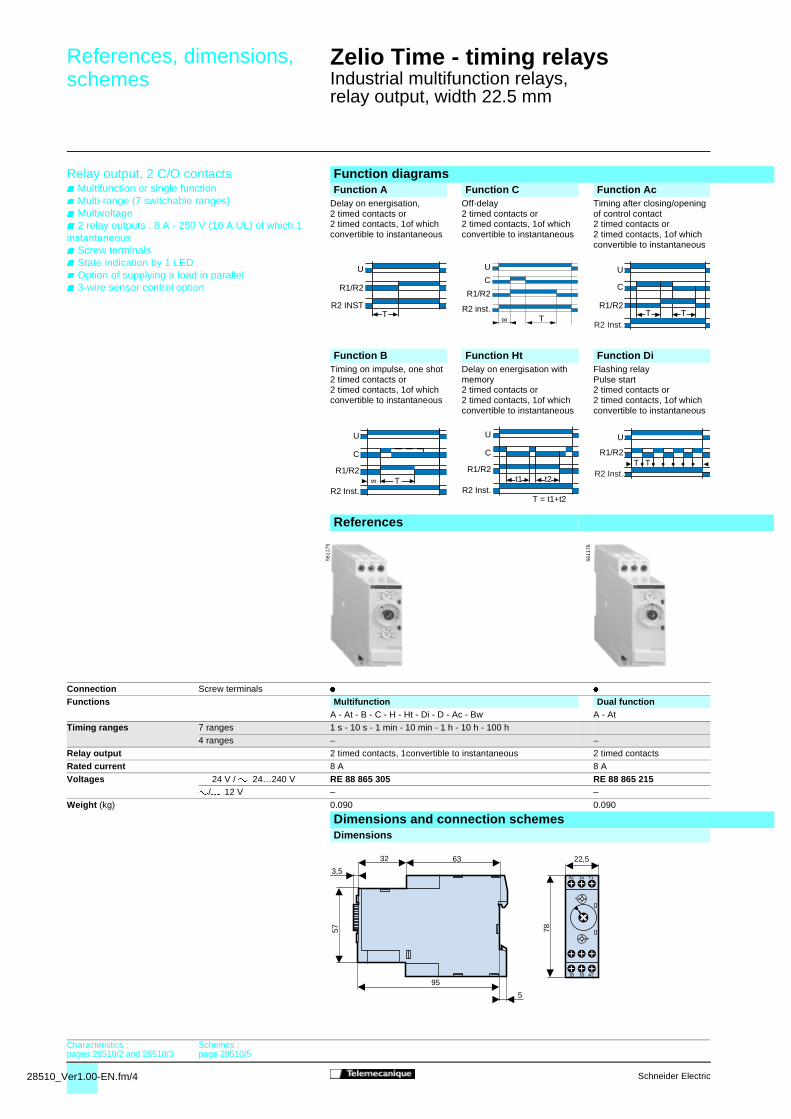
Relay output, 2 C/O contacts Multifunction or single function Multi-range (7 switchable ranges) Multivoltage 2 relay outputs : 8 A - 250 V (10 A UL) of which 1 instantaneous Screw terminals State indication by 1 LED Option of supplying a load in parallel 3-wire sensor control option
Function diagramsFunction A Function C Function Ac
Delay on energisation, 2 timed contacts or 2 timed contacts, 1of which convertible to instantaneous
Off-delay2 timed contacts or 2 timed contacts, 1of which convertible to instantaneous
Timing after closing/opening of control contact2 timed contacts or 2 timed contacts, 1of which convertible to instantaneous
Function B Function Ht Function DiTiming on impulse, one shot2 timed contacts or 2 timed contacts, 1of which convertible to instantaneous
Delay on energisation with memory2 timed contacts or 2 timed contacts, 1of which convertible to instantaneous
Flashing relay Pulse start2 timed contacts or 2 timed contacts, 1of which convertible to instantaneous
References
Connection Screw terminals
Functions Multifunction Dual functionA - At - B - C - H - Ht - Di - D - Ac - Bw A - At
Timing ranges 7 ranges 1 s - 10 s - 1 min - 10 min - 1 h - 10 h - 100 h
4 ranges – –
Relay output 2 timed contacts, 1convertible to instantaneous 2 timed contacts
Rated current 8 A 8 A
Voltages 24 V / 24…240 V RE 88 865 305 RE 88 865 215/12 V – –
Weight (kg) 0.090 0.090
Dimensions and connection schemesDimensions
U
R1/R2
R2 INSTT
U
C
R1/R2
∞ TR2 inst.
U
C
R1/R2T T
R2 Inst.
U
C
R1/R2∞ T
R2 Inst.t1
R1/R2
C
U
t2
T = t1+t2R2 Inst.
U
R1/R2T T
R2 Inst.
5611
75
5611
76
32
3,5
95
5
57 78
63 22,5
18 16 A2
A1 15 Y1
Characteristics :pages 28510/2 and 28510/3
Schemes :page 28510/5

28510_Ver1.00-EN.fm/5Schneider Electric
0
Function K Function At Function H Function D Function BwDelay on de-energisationTrue off-delay(without auxiliary supply)2 timed contacts
Timing on energisationwith memory2 timed contacts or 2 timed contacts, 1of which convertible to instantaneous
Timing on energisation2 timed contacts or 2 timed contacts, 1of which convertible to instantaneous
Flashing relayStart after pause2 timed contacts or 2 timed contacts, 1of which convertible to instantaneous
Pulse output (adjustable)2 timed contacts or 2 timed contacts, 1of which convertible to instantaneous
Single function MultifunctionK A - At - B - C - H - Ht - Di - D - Ac - Bw
– 1 s - 10 s - 1 min - 10 min - 1 h - 10 h - 100 h
0.6 s - 2.5 s - 20 s - 160 s –
2 timed contacts 2 timed contacts, 1convertible to instantaneous
8 A 8 A
RE 88 865 265 –– RE 88 865 3030.090 0.090
Connection schemesAll functions except K Function K
TR1/R2
U U
C
R1/R2t1 t2
T = t1+t2R2 Inst.
TR1/R2
U
R2 Inst.
U
T TR1/R2
R2 Inst.
U
C
T TR1/R2
R2 Inst.
5611
76
5611
76
U
A1R1 R215
A21816
25/21
28/2426/22
Y1
+U
A1
A2
R1 R2
15
1816
25
2826
+
Characteristics :pages 28510/2 and 28510/3
Dimensions :page 28510/4

28450-EN_Ver5.0.fm/2 Schneider Electric
References :pages 28504/2 to 28505/
3
Zelio Time - timing relaysIndustrial relays, relay output,width 22.5 mm
The RE7 range of relays, with only 23 references, covers all timing applications.
These relays offer multi-range timing from 50 ms to 300 h.
They are multivoltage.
Three models combine several different functions : multifunction relays.
These products have a transparent, hinged flap on their front face to avoid any accidental alteration of the settings. This flapcan be directly sealed.
(1) RE7-RBppMW : current peak on energisation = 1 A / 30 ms.
Presentation
Environment
Conforming to standards IEC 61812-1, EN 61812-1Approvals CSA, GL pending, ULe marking Zelio Time timing relays conform to
European regulations relating to e marking
Ambient air temperature Storage °C - 40…+ 85around the device Operation °C - 20…+ 60
Permissible relative humidity range Conforming to IEC 60721-3-3 15…85 % Environmental class 3K3
Vibration resistance Conforming to IEC 6068-2-6, 10 to 55 Hz a = 0.35 msShock resistance Conforming to IEC 6068-2-27 15 gn - 11 ms
Degree of protection Casing IP 50Terminals IP 20
Degree of pollution Conforming to IEC 60664-1 3
Overvoltage category Conforming to IEC 60664-1 III
Rated insulation voltage Conforming to IEC V 250Between contact circuit and power supply or between contact circuit and control inputs
Conforming to CSA V 300
Test voltage for insulation tests Dielectric test kV 2.5d'isolement Shock wave kV 4.8
Voltage limits Power supply circuit 0.85…1.1 Uc
Frequency limits Power supply circuit Hz 50/60 ± 5 %
Disconnection value Power supply circuit > 0.1 UcMounting position In relation to normal vertical mounting
planeAny position
without derating
Connection Maximum c.s.a. Flexible cable without cable end mm2 2 x 2.5 Flexible cable with cable end mm2 2 x 1.5
Tightening torque N.m 0.6…1.1
Immunity to electromagnetic interference (EMC) (Application class 2 conforming to EN 61812-1)
Electrostatic discharge Conforming to IEC 61000-2-6 Level 3 (6 kV contact, 8 kV air)Electromagnetic fields Conforming to IEC 61000-4-3 Level 3 (10 V/m)Fast transients Conforming to IEC 61000-4-4 Level 3 (2 kV)Shock waves Conforming to IEC 61000-4-5 Level 3 (2 kV)Radiated and conducted CISPR11 Group 1 class Aemissions CISPR22 Class A
Consumption
a 50/60 Hz cAverage consumption 24 V 48 V 110 V 240 V 24 V 48 V 110 V 240 V
RE7-pp11BU VA 0.7 1.6 1.8 8.5 W 0.5 1.2 – –RE7-pp12BU and RE7-pp13BU VA 1.2 2 2.8 12.5 W 0.8 1.6 – –RE7-ppppMW (1) VA 2 2.5 3.2 6 W 2 1 3.2 2
5608
72General characteristics

28450-EN_Ver5.0.fm/3Schneider Electric
10
1
0,1
0,010 1 2 3 4 5 6 7 8
A
1
0,6
0,5
0,9
0,8
0,7
0,4
0,31 0,8 0,6 0,5 0,4 0,3 0,2
300
40
30
200
100
50
20
100,1 0,2 0,5 1 2 5 2010
1
2
3
A
RE7
K
+
–
Red
uctio
n fa
ctor
k
References :pages 28504/2 to 28505/
3
Current broken in A Power factor on breaking (cos ) Current in A
Mill
ions
of o
pera
ting
cycl
es
Vol
tage
in V
Zelio Time - timing relaysIndustrial relays, relay output,width 22.5 mm
consumption equal to 0.1 A and cos = 0.3For 0.1 A, curve 1 indicates a durability of approximately 1.5 million operating cycles.As the load is inductive, it is necessary to apply a reduction coefficient k to this number of cyclesas indicted by curve 2.
For cos = 0.3 : k = 0.6The electrical durability therefore becomes :1.5 106 operating cycles x 0.6 = 900 000 operating cycles
Timing characteristics
Setting accuracy As % of the full-scale value ± 10 %Repeat accuracy ± 0.2 %
Influence of voltage In the voltage range, 0.85…1.1 Un < 0.2 %Influence of temperature < 0.07 %/°CImmunity timeto microbreaks
ms 3
Minimum control pulse ms 20 (except RE7-RB1pMW : 1 s)Reset time ms 50
Output circuit characteristics
Maximum switching voltage V z 250
Mechanical durability In millions of operating cycles 20
Current limit Ith A 8 (except RE7-RBppMW : 5 A)
Rated operational limits at 70 °C 24 V 115 V 250 VConforming to IEC 60947-5-1/1991 AC-15 A 3 3 3and VDE 0660 DC-13 A 2 0.2 0.1
Minimum switching capacity 12 V/10 mAContact material 90/10 nickel silver
(except RE7-RBppMU : gold flashed silver alloy)
Remote control input characteristics
Maximum voltage Applicable to inputs V 60Y1Z2, X1Z2, X2Z2
Signal delivered by control inputs Switching current mA < 1Y1Z2, X1Z2, X2Z2 Maximum distance m 50 No galvanic insulation between Compatibility 3/4-wire PNP and NPN Telemecanique sensors or otherthese inputs and the supply sensors without an internal load
Potentiometer for connection between terminals Z1Z2, Z3Z2
Type Linear at ± 20 %Resistance k 47 ± 20 %Power W 0.2Maximum distance m 25 by shielded cable : shielding linked to terminal Z2
a.c. load d.c. loadCurve 1 Curve 2 Load limit curveElectrical durability of contacts on resistive loadin millions of operating cycles
Reduction factor k for inductive loads(applies to values taken fromthe durability curve opposite)
A RE7-RBppMW A RE7-RBppMW1 L/R = 20 ms
Example : 2 L/R with load protection diode3 Resistive load
An LC1-F185 contactor supplied with 115 V/50 Hz for a consumption of 55 VA or a current
General characteristics (continued)

28505-EN_Ver2.0.fm/2 Schneider Electric
Functions,references
Zelio Time - timing relays 0
Industrial multifunction relays,relay output, width 22.5 mm
Output 2 C/O contactsMultiple timing ranges
Function diagramsFunction A Function Ac Function C
Start on energisation
External control for start of time delay
Off-delay with external control for start of time delay
Function KOff-delay
(1) If the device has been stored, de-energised, for more than a month, it must be energised for about 15 seconds in order to activate it. Subsequently, it only takes 1 second to start the time delay. d If this time is not complied with, the relay remains energised indefinitely.
References
Functions A Ac C KTiming ranges 0.05 s...300 h
10 ranges0.05 s...300 h10 ranges
0.05 s...300 h10 ranges
0.05 s…10 min7 ranges
Voltages c or a 24 V p p p –a 110…240 V p p p –
a or c 42…48 V p p p –c or a 24…240 V – – – p
References RE7 TP13BU RE7 MA13BU symmetrical
RE7 RL13BU low level contact
RE7 RB13MW
Weight (kg) 0.150 0.150 0.150 0.150
Dimensions and connection schemesDimensions
Rail mounting Screw fixing
15/18 (25/28)
15/16 (25/26)
t
Supply
C/O
15/18 (25/28)
Y1Z2
15/16 (25/26)
trta
Supply
Start
C/O15/1815/16
t
Supply
C/O
Start
15/18 (25/28)15/16 (25/26)
t
> 1 s (1)Supply
C/O
5609
02
5609
03
5609
04
5609
04
89,5
80
82
22,5
78
66
78
Ø4
Characteristics :pages 28450/2 and 28450/3
Schemes :pages 28506/2 and 28506/3

28505-EN_Ver2.0.fm/3Schneider Electric
0
Function H Function Hi Function Qt Function Qg Function DPulse-on energisation.Start on energisation
Start on opening of external control contact
Timing relays for star-delta starters
Timing relays for star-delta starters
Symmetrical flasher, start with output in rest position
Function DiSymmetrical flasher start with output in operating position
H Hi D Qt Qg A, C, H, Hi, D, Di A, C, H, Hi, D, Di, Qg, Qt0.05 s...300 h10 ranges
0.05 s...300 h10 ranges
0.05 s...300 h10 ranges
0.05 s...300 h10 ranges
0.05 s...300 h10 ranges
0.05 s...300 h10 ranges
0.05 s...300 h10 ranges
p p p p p p p –p p p p p p p –
p p p p p p p –– – – – – – – pRE7 PP13BU RE7 PD13BU RE7 CP13BU RE7 YA12BU RE7 YR12BU RE7 ML11BU RE7 MY13BU RE7 MY13MW
0.150 0.150 0.150 0.150 0.150 0.150 0.150 0.150
ConnectionsRE7 TP13BU
RE7 RB13MW
RE7 YA
RE7 RL13BU, RE7 MA13BURE7 PD13BU
RE7 PP13BURE7 CP13BU
RE7 YR RE7 MY13BU RE7 MY13MW
15/18 (25/28)15/16 (25/26)
t
Supply
C/O
15/18
Y1Z2
15/16
t
Supply
Start
C/O
t 50 ms
15/18
15/16
25/28
25/26
K1
K3
Supply
C/O1
star
delta
C/O2
t 50 ms
17/18
17/28
K1
K3
Supply
C/O1
star
delta
C/O2
15/18 (25/28)15/16 (25/26)
t t
Supply
C/O
t t
Supply
C/O
5609
05
5609
05
5609
06
5609
07
5609
07
5609
08
5609
08
A1 15 B125 (21)Z1 B2
28 (24) Z218
26 (22)16 A2
1815B
1
A1
B2
A2
16 2825 (2
1)
26
(24)
(22)
A1 1525Z1
26 Z22818 16 A2
1815A
1A
2
16 2825
26
A1 15 B125 B2
28 26 Z218 16 A2
1815B
1
A1
B2
A2
16 2825
26
A1 15 B125 (21)Y1 B2
26 (22)28 (24) Z218 16 A2
1815B
1
A1
B2
A2
16 2825
26 (24)
(21)
(22)
A1 15 B125 (21)Z1 B2
26 (22)28 (24) Z218 16 A2
1815B
1
A1
B2
A2
16 2825
26 (24)
(21)
(22)
B11717
A1B2
28 26 Z218 16 A2
18
B1
A1
B2
A2
16 28
1726
A1 15 B125 (21)Z1 Y1
26 (22)28 (24) Z218 16 A2
1815B
1
A1
A2
16 28 (24)
25 (21)
26 (22)
A1 15 Y125 (21)Z1 X1
26 (22)28 (24) Z218 16 A2
1815A
1A
2
16 2825
26 (24)
(21)
(22)
Characteristics :pages 28450/2 and 28450/3
Schemes :pages 28506/2 and 28506/3
Dimensions :page 28505/3

28506-EN_Ver1.1.fm/2 Schneider Electric
Schemes Zelio Time - timing relays 0
Industrial relays, relay output,width 22.5 mm
Recommended application schemesRE7 TL, TM, TP, CL, CP, ML, MY
Start on energisation
RE7 TM, MA, MV, RM, RL, PM, PD, ML, MYStart by external control
RE7 TM, PM, ML, MY
External control of partial stop
RE7 MA, MV, RA, RM
Start by external control
RE7 RBStart on de-energisation
RE7 RAStart by external control
RE7 PPStart on energisation
RE7 PEStart on energisation
RE7 CVSelection of starting phase
RE7 TM, TP, MA, RA, RM, PP, PM, ML, MYConnection of potentiometer
RE7 MV
Connection of potentiometers to asymmetrical timing relays
RE7 CV
Connection of potentiometers
Connection precautions
No galvanic isolation between supply terminals A1, A2, B1, B2 and control inputs X1, Y1, Z1, Z2.
(1) a 110…240 V except RE7 MY13MW : z 24…240 V.(2) z 12…48 V (3) z 24 V(4) Adjustment of the On-delay period(5) Adjustment of the Off-delay period(6) Start during the On-delay period : X2, Z2 linked. Start during the Off-delay period : X2, Z2 not linked.(7) Off-delay adjustment (tr) (contact 15/16 closed).(8) On-delay adjustment (ta) (contact 15/18 closed).
B1 A1B2
A2(1)
(2)
(3) B1 A1B2
A2
Y1
Z2(1)
(2)
(3)
B1 A1B2
A2
X1
Z2(1)
(2)
(3) B1 A1B2
A2
X1
Z2(1)
(2)
(3)
A1
A2A1
A2
Y1 B2
A2
Y1
+
–
B1
A2
Y1
+
–
B1 A1B2
A2
(1)
(2)
(3) B1 B3B2
A2
(1)
(3) B1 A1B2
A2
X2
Z2(6)(1
)(2
)
(3)
Z1Z2
A2Z1Z3 (4) (5)
Z2A2
Z1Z3 (7) (8)
Z2A2A2 Z2
Sup
ply
X1 or Y1 or Z1
Characteristics :pages 28450/2 and 28450/3
References :pages 28504/2 to 28505/3

28506-EN_Ver1.1.fm/3Schneider Electric
Schemes (continued) Zelio Time - timing relays 0
Industrial relays, relay output,width 22.5 mm
Recommended application schemes (continued)
Power schemeRE7 YA12BU
Control schemesStar-delta function with double On-delay timing Qt
Power schemeRE7 YR12BU
Control schemesStar-delta function with contact for switching to star connection Q
No galvanic isolation between supply terminals A1, A2, B1, B2 and supply terminal Z2.This terminal must therefore never be used (factory setting)
Control of several relays with a single external control contact Connection of a Telemecanique 3-wire NPN or PNP sensor
It is advisable to follow the recommended wiring schemes detailed above and on previous pages. However, the connections below are possibleif the restrictions given are taken into account.
Connection of an external control contact without using terminal Z2 : Connection of a Telemecanique 3-wire NPN or PNP sensor without using terminal Z2 :
- possible on all RE7 relays with external control option except RE7 RA11BU,- d.c. supply only.
- only possible on relay RE7ppppBU,- d.c. supply only.
V2
U2
W2
W1
V1
U1
F2
K2
12
34
56
K11
2
34
56
M1
K3
12
34
56
L1 L2 L3
12
34
56
3K1
A1
A2
96
F2
1516
K1T
2122
K3
2122
1314
S1
S2
K1T
A1
A2
1314 K1
K2
A1
A2
K3
A1
A2
2528
K1T
2122
K1
1413
K2
A1 15 B125 B2
28 26 Z218 16 A2
1815B
1
A1
B2
A2
16 2825
26
Y N ∆
95
F3 Terminal block
K1T = relay RE7 YA
V2
U2
W2
W1
V1
U1
F2
K2
12
34
56
K1
12
34
56
M1
K3
12
34
56
L1 L2 L3
12
34
56
3K1
A1
A2
9596
F2
2122
K3
F3
2122
1314
S1
S2
K1T
A1
A2
K3
A1
A2
K2
A1
A2
1413
5354
K2
2817
2122
K1
1817
K1T K2
1413
K1
B11717
A1B2
28 26 Z218 16 A2
18
B1
A1
B2
A2
16 28
1726
Y N∆
Terminal block
K1T = relay RE7 YR
Z2A2Z2A2 Z2A2
Sup
ply
A1,B1 or B12Y1 or X1
A1,B1 or B12Y1 or X1
A1,B1 or B12Y1 or X1
BNBK NPN
PNPBU
+
Z2A2
Sup
ply
A1,B1 or B12Y1 or X1
+
Z2A2
A1,B1 or B12Y1 or X1
+
Z2A2
A1,B1 or B12Y1 or X1
BNBK NPNBU
Y1
+
B1B2
Z2A2
24or48 V
BNBK PNPBU
Y1
+
B1B2
Z2A2
24or48 V
Characteristics :pages 28450/2 and 28450/3
References :pages 28504/2 to 28505/3

28504-EN_Ver2.0.fm/2 Schneider Electric
Functions,references
Zelio Time - timing relays 0
Industrial, single-function relays,relay output, width 22.5 mm
Output 1 C/O contactMultiple timing ranges
Function diagramsFunction A Function Wt Function At
Delay on energisation
External control for start of time delay
External control for partial stop of time delay (with memory)
Function H Function Hi Function HtPulse-on energisationStart on energisation
Start on opening of external control contact
External control for partial stop of time delay (with memory)
References
Functions A A, Wt, At Ac Ae, AfTiming ranges 0.05 s...300 h
10 ranges0.05 s...300 h10 ranges
0.05 s...300 h10 ranges
0.05 s...300 h10 ranges
Voltages c or a 24 V p p p pa 110…240 V p p p pa or c 42…48 V – p p pc or a 24…240 V – – – –
References RE7 TL11BU RE7 TM11BU RE7 MA11BU
RE7 MV11BU
Weight (kg) 0.150 0.150 0.150 0.150
Dimensions and connection schemesDimensions
Rail mounting Screw fixing
15/18 (25/28)
15/16 (25/26)
t
Supply
C/O
15/1815/16
(Y1Z2)
t
Supply
Partialstop
C/O
15/1815/16
(X1Z2)
t t = t1 + t2 + t3
t3t2
t1
Supply
Partialstop
C/O
15/18 (25/28)15/16 (25/26)
t
Supply
C/O
15/18
Y1Z2
15/16
t
Supply
Start
C/O
15/18
X1Z2
15/16
tt = t1 + t2 + t3
t1 t2 t3
Supply
Partialstop
C/O
5608
73
5608
73
5608
74
5608
74
89,5
80
82
22,5
78
66
78
Ø4
Characteristics :pages 28450/2 and 28450/3
Schemes :pages 28506/2 and 28506/3

28504-EN_Ver2.0.fm/3Schneider Electric
0
Function Ac Function Ae Function Af Function K Function HfRemote control for partial stop of time delay
External control for start of time delay
Asymmetrical On-delay and Off-delay with external control
Off-delay
Remote control for stop of time delay
Function D Function L Function Li Function LtSymmetrical flasher, start with output in rest position
Start with output in rest position (X2Z2 not linked)
Asymmetrical flasher. Start with output in operating position(X2Z2 linked)
External control for partial stop of time delay
(1) If the device has been stored, de-energised, for more than a month, it must be energised for about 15 seconds in order to activate it. Subsequently, it only takes 1 second to start the time delay. d If this time is not complied with, the relay remains energised indefinitely.
K Hf H Hi, Ht D L, Li, Lt0.05 s…10 min7 ranges
0.05 s...300 h10 ranges
0.05 s...300 h10 ranges
0.05 s...300 h10 ranges
0.05 s...300 h10 ranges
0.05 s...300 h10 ranges
– p p p p p– p p p p p– p – p – pp – – – – –
RE7 RB11MW RE7 RA11BURE7 RM11BU low level contact
RE7 PE11BU RE7 PM11BU RE7 CL11BU RE7 CV11BU
0.150 0.150 0.150 0.150 0.150 0.150
ConnectionsRE7 TL11BU
RE7 RB11MW
RE7 PE11BU
RE7 TM11BU, RE7 RA11BURE7 RM11BU, RE7 PM11BU
RE7 MA11BURE7 MV11BU
RE7 CL11BU RE7 CV11BU
15/1815/16
X1Z2
Y1Z2
t2t1 ts t4t3 ts
Partial stoptime delay
Start
C/O
15/18 (25/28)
Y1Z2
15/16 (25/26)
trta
Supply
Start
C/O t1 t2 t3 t4
t1 + t2 = tat3 + t4 = tr
Supply
C/O
External control
15/18 (25/28)15/16 (25/26)
t
> 1 s (1)
Supply
C/O 15/18
X1Z2
Y1Z2
15/16
tst1 t2
Start
C/O
Partialstop
15/18 (25/28)15/16 (25/26)
t t
Supply
C/O
tatr
Supply
C/O 15/18 (25/28)15/16 (25/26)
ta tr
Supply
C/O15/18 (25/28)
X1Z2
15/16 (25/26)
t1 t3 t4t2ts ts
Supply
C/O
Partialstop
5608
75
5608
75
5608
76
5608
76
5608
77
5608
77
A1 15 B1
18 16 A2
1815B
1
A1
A2
16
A1 15
18 16 A2
1815A
1A
2
16
A1 15 B1
18 16 A2
1815B
1
A1
A2
16
A1 15 B1Z1 B2
Y1X1 Z218 16 A2
1815B
1
A1
B2
A2
16
A1 15 B1Z1 B2
Y1X1 Z218 16 A2
1815B
1
A1
B2
A2
16
A1 15 B1
18 16 A2
1815B
1
A1
A2
16
A1 15 B1Z3Z1 B2
X2X1 Z218 16 A2
1815B
1
A1
B2
A2
16
Characteristics :pages 28450/2 and 28450/3
Dimensions :page 28504/2
Schemes :pages 28506/2 and 28506/3

28461-EN_Ver4.0.fm/2 Schneider Electric
The RE8 range of relays is designed for simple and repetitive applications, providing basic functions.
Each relay comprises :- a single timing range,- a C/O output relay
These products have a transparent, hinged flap on their front face to avoid any accidental alteration of the settings. Thisflap can be directly sealed.
Presentation
5609
53
Environment
Conforming to standards IEC 61812-1, EN 61812-1
Approvals CSA, GL pending, ULemarking Zelio Time timing relays conform to European regulations
relating to e markingAmbient air temperaturearound the device
Storage °C - 40…+ 85Operation °C - 20…+ 60
Permissible relative humidity range Conforming to IEC 60721-3-3 15…85 % Environmental class 3K3
Vibration resistance Conforming to IEC 6068-2-6, 10 to 55 Hz a = 0.35 ms
Shock resistance Conforming to IEC 6068-2-27 15 gn - 11 msDegree of protection Casing IP 50
Terminals IP 20
Degree of pollution Conforming to IEC 60664-1 3
Overvoltage category Conforming to IEC 60664-1 IIIRated insulation voltage Conforming to IEC V 250
Conforming to CSA V 300Test voltage for insulation tests Dielectric test kV 2.5
Shock wave kV 4.8
Voltage limits Power supply circuit 0.9…1.1 Uc
Frequency limits Power supply circuit Hz 50/60 ± 5 %
Disconnection value Power supply circuit > 0.1 UcMounting position In relation to normal
vertical mounting planeAny position
without deratingConnection Flexible cable without cable end mm2 2 x 2.5maximum c.s.a. Flexible cable with cable end mm2 2 x 1.5
Tightening torque N.m 0.6…1.1
Immunity to electromagnetic interference (EMC) (Application class 2 conforming to EN 61812-1)
Electrostatic discharge Conforming to IEC 61000-2-6 Level 3 (6 kV contact, 8 kV air)
Electromagnetic fields Conforming to IEC 61000-4-3 Level 3 (10 V/m)
Fast transients Conforming to IEC 61000-4-4 Level 3 (2 kV)
Shock waves Conforming to IEC 61000-4-5 Level 3 (2 kV)
Radiated and conducted emissions CISPR11 Group 1 class ACISPR22 Class A
Consumption
Consumption a c24 V 110 V 240 V 380 V 415 V 24 V
RE8-TA, RA, CL, PE, PU, PT VA 0.7 1.8 8.5 – – W 0.5RE8-YG, RB VA 0.9 2.5 13 – – W 0.5RE8-YA VA 0.9 2.5 13 8 9 W 0.7
Zelio Time - timing relaysIndustrial single-function relays,relay output, width 22.5 mm, optimum
General characteristics
References :pages 28507/2 to 28508/3
Dimensions:pages 28507/2 and
28508/2Schemes :
pages 28507/2 and 28507/3

28461-EN_Ver4.0.fm/3Schneider Electric
1
0,6
0,5
0,9
0,8
0,7
0,4
0,31 0,8 0,6 0,5 0,4 0,3 0,2
RE8
K
+
–
10
1
0,1
0,010 1 2 3 4 5 6 7 8
A
300
40
30
200
100
50
20
100,1 0,2 0,5 1 2 5 2010
1
2
3
A
Zelio Time - timing relaysIndustrial single-function relays,relay output, width 22.5 mm, optimum
An LC1-F185 contactor supplied with 115 V/50 Hz for a consumption of 55 VA or a currentconsumption equal to 0.1 A and cos = 0.3For 0.1 A, curve 1 indicates a durability of approximately 1.5 million operating cycles.As the load is inductive, it is necessary to apply a reduction coefficient k to this number of cyclesas indicated by curve 2.
For cos = 0.3 : k = 0.6The electrical durability therefore becomes :1.5 106 operating cycles x 0.6 = 900 000 operating cycles
Timing characteristics
Setting accuracy As % of the full-scale value ± 20 %
Repeat accuracy < 1 %
Influence of voltage In the voltage range, 0.9…1.1 Un < 2.5 %
Influence of temperature <0.2 %/°C
Immunity to microbreaksms 3
Minimum control pulse ms 26 (except RE8-YG : 60)
Reset time ms 50
Output circuit characteristics
Maximum switching voltage V z 250
Mechanical durability In millions of operating cycles 20
Current limit Ith A 8
Rated operational limits at 70 °C 24 V 115 V 250 VConforming to IEC 60947-5-1/1991 AC-15 A 3 3 3and VDE 0660 DC-13 A 2 0.2 0.1
Minimum switching capacity 12 V/10 mA
Contact material 90/10 nickel silver
Remote control input characteristics
Signal delivered by No-load voltage Supply voltagecontrol input Y1 Switching current mA < 10 No galvanic insulation between Maximum distance m 50this input and the supply Compatibility 2-wire sensors c with leakage current < 1 mAa.c. load d.c. loadCurve 1 Curve 2 Load limit curveElectrical durability of contacts on resistive loadin millions of operating cycles
Reduction factor k for inductive loads (applies to values taken from the durability curve opposite)
A RE8-RBppBUTQ A RE8-RBppBUTQ1 L/R = 20 ms
Example : 2 L/R with load protection diode3 Resistive load
General characteristics (continued)
Current broken in A Power factor on breaking (cos ) Current in A
Mill
ions
of o
pera
ting
cycl
es
Red
uctio
n fa
ctor
k
Vol
tage
in V
References :pages 28507/2 to 28508/3
Dimensions:pages 28507/2 and
28508/2Schemes :
pages 28507/2 and 28507/3

28507-EN_Ver3.0.fm/2 Schneider Electric
Functions,references
Zelio Time - timing relays 0
Industrial single-function relays, optimumrelay output, width 22.5 mm
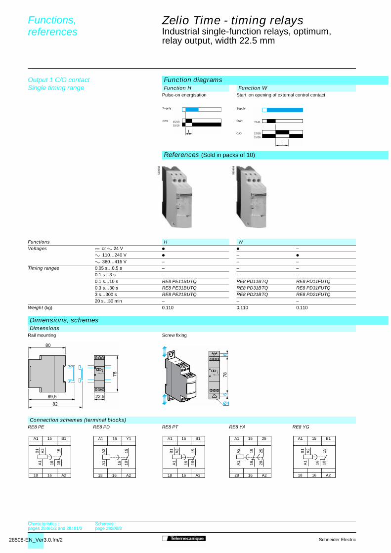
Output 1 C/O contactSingle timing range
Function diagramsFunction A Function C
Start on energisation With control contact
References (Sold in packs of 10)
Functions A CVoltages c or a 24 V p p –
a 110…240 V p – pa 380…415 V – – –
Timing ranges 0.05 s…0.5 s – – –0.1 s…3 s RE8 TA61BUTQ – –0.1 s…10 s RE8 TA11BUTQ RE8 RA11BTQ RE8 RA11FUTQ0.3 s…30 s RE8 TA31BUTQ RE8 RA31BTQ RE8 RA31FUTQ3 s…300 s RE8 TA21BUTQ RE8 RA21BTQ RE8 RA21FUTQ20 s…30 min RE8 TA41BUTQ – RE8 RA41FUTQ
Weight (kg) 0.110 0.110 0.110
DimensionsDimensions
Rail mounting Screw fixing
15/1815/16
t
Supply
C/O
15/1815/16
t
Supply
Start
C/O
5609
54
5609
54
89,5
80
82
22,5
78
Ø4
66
78
Characteristics :pages 28461/2 and 28461/3
Schemes :page 28507/3

28507-EN_Ver3.0.fm/3Schneider Electric
0
Function K Function DOff-delay
Symmetrical
K Dp pp p– –
RE8 RB51BUTQ –– –RE8 RB11BUTQ RE8 CL11BUTQRE8 RB31BUTQ –– –– –
0.110 0.110
SchemesConnection schemes Recommended application schemes
RE8 TA, CL
RE8 RA
RE8 RB
RE8 TA, CL
RE8 RA
Control of several relays with a single external control contact Connection of a c 2-wire sensorRE8 RA, RE8 PD
The external control contact C may be an electronic control device, for example a 2-wire sensor. In this case A1-A2 = c 24 V and the control device can only control up to a maximum of 4 relays.
Leakage current (open state) If < 1 mA.
15/1815/16
t > 80 ms
Supply
C/O 15/1815/16
t t
Supply
C/O
5609
54
5609
54
A1 15 B1
18 16 A2
1815B
1
A2
A1
16
A1 15 Y1
18 16 A2
1815A
2A
1
16
A1 15 B1
18 16 A2
1815B
1
A2
A1
16
B1 A2
A1
A1
A2
Y1
start
Y1A2
Y1A2
Y1A2
A1A1 A1C
Y1
–
+
A1
A2
If
Characteristics :pages 28461/2 and 28461/3
Dimensions :page 28507/2
28508-EN_Ver3.0.fm/2 Schneider Electric
Functions,references
Zelio Time - timing relays 0
Industrial single-function relays, optimum,relay output, width 22.5 mm
Output 1 C/O contactSingle timing range
Function diagramsFunction H Function W
Pulse-on energisation Start on opening of external control contact
References (Sold in packs of 10)
Functions H WVoltages c or a 24 V p p –
a 110…240 V p – pa 380…415 V – – –
Timing ranges 0.05 s…0.5 s – – –0.1 s…3 s – – –
0.1 s…10 s RE8 PE11BUTQ RE8 PD11BTQ RE8 PD11FUTQ0.3 s…30 s RE8 PE31BUTQ RE8 PD31BTQ RE8 PD31FUTQ3 s…300 s RE8 PE21BUTQ RE8 PD21BTQ RE8 PD21FUTQ20 s…30 min – – –
Weight (kg) 0.110 0.110 0.110
Dimensions, schemesDimensions
Rail mounting
Screw fixing
Connection schemes (terminal blocks)RE8 PE
RE8 PD
RE8 PT
RE8 YA
RE8 YG
15/1815/16
t
Supply
C/O
15/18
Y1A1
15/16
t
Supply
Start
C/O
5609
68
5609
68
89,5
80
82
22,5
78
Ø4
66
78
A1 15 B1
18 16 A2
1815
16
B1
A2
A1
A1 15 Y1
18 16 A2
1815A
2A
1
16
A1 15 B1
18 16 A2
1815
16
B1
A2
A1
A1 15 25
28 16 A2
1615A
2A
1
2825
A1 15 B1
18 16 A2
1815B
1A
2A
1
16
Characteristics :pages 28461/2 and 28461/3
Schemes :page 28508/3

28508-EN_Ver3.0.fm/3Schneider Electric
0
Function He Function Qc Function QePulse-on energisation, start on de-energisation
Timing relay for star-delta starters
Timing relay for star-delta starters
He Qc Qep p p – –p p – p –
– – – – pRE8 PT01BUTQ – – – –– – – – –
– RE8 YG11BUTQ – – –– RE8 YG31BUTQ RE8 YA32BTQ RE8 YA32FUTQ RE8 YA32QTQ– RE8 YG21BUTQ – – –
– – – – –0.110 0.110 0.110 0.110 0.110
Recommended application schemesPulse-on energisation relaysRE8 PE, RE8 PT RE8 PD
Timing relays for star-delta startersRE8 YG, RE8 YA RE8 YG RE8 YA
(1) K1T : RE8-YGp1ppTQ (1) K1T : RE8-YA32ppTQNote : Correct operation of the star-delta starter associated with the RE8 YG is only possible if the wiring scheme is strictly complied with.
15/1815/16
t < t
> 80 ms
Supply
C/O
t 50 ms
15/18
15/16
Supply
Star
Deltat 80 ms
15/16
25/28
Supply
C/O
N/O
5609
68
5609
69
5609
69
B1 A2
A1
A1
A2
Y1
+
start
– KM2 – KM3 – KM1
U1
V1
W1
U2
V2
W2
– Q1
L1 L2 L3
– Rth
Y
(1)
Y
A1
A2
A1
A2
A1
A2
A1
A2
16 15
L
(1)
Y
A1
A2
A1
A2
A1
A2
A1
A2
1516
2528
L
Characteristics :pages 28461/2 and 28461/3
Dimensions :page 28508/2

28511_Ver1.00-EN.fm/2 Schneider Electric
Characteristics Zelio Time - timing relays 0
Universal plug-in relays, 8-pin,relay output, width 35 mm
Timing characteristicsRepeat accuracy(with constant parameters)
Conforming to IEC 1812-1 ± 0.5 %
Drift Temperature ± 0.05 % / °C
Voltage ± 0.2 % / VFull scale setting accuracy Conforming to IEC 1812-1 ± 10 % at 25 °C
Minimum duration of control impulse
Typical ms 30
Typical under load ms 100
Maximum reset time by de-energisation
Typical ms 100
Immunity timeto microbreaks
Typical ms > 10
Supply characteristicsMultivoltage supply Depending on version, see pages 28511/4 and 28511/5
Frequency Hz 50/60
Operating range 85…110 Un % (85…120 Un for /12 V )On-load factor 100 %
Maximum power consumption
Depending on model
24 V W 0.6
240 V W 1.5
240 V VA 32
Output characteristicsOutput type Relay, 1 or 2 C/O contacts, AgNi (cadmium -free)Breaking capacity 2000 VA, 80 W
Maximum breaking current A 8, 8
Minimum breaking current mA 10/ 5 V
Maximum switching voltage V /250
Electrical life 105 operations 8 A 250 V resistive
Mechanical life 5 x 10⁶ operationsDielectric strength Conforming to IEC 1812-1 kV 2.5/1min/1 mA/50 Hz
Impulse voltage Conforming to IEC 664-1,IEC 1812-1
kV 5, wave 1.2/50 µs
Display characteristicsState indication by 1 LED Green Operating status indication
Pulsing : relay energised, no timing in progress (except Di-D and Li-L)
Flashing : timing in progress
On steady : relay energised, no timing in progress
Input characteristicsInput type V Volt-free contact (no potential)
Control possible by 3-wire sensor with PNP output, maximum residual voltage : 0.4 V whatever the supply voltage of the timer
References :pages 28511/4 and 28511/5
Dimensions :page 28511/4
Schemes :page 28511/5

28511_Ver1.00-EN.fm/3Schneider Electric
Characteristics Zelio Time - timing relays 0
Universal plug-in relays, 8-pin,relay output, width 35 mm
General characteristicsConforming to standards IEC 1812-1, EN 50081-1/2, EN 50082-1/2, LV directives (73/23/EEC + 93/68/EEC
(CE marking) + EMC (89/336/EEC + IEC 669-2-3)
Approvals c UR us, CSA, GL
Temperature limits Operation °C - 20…+ 60
Storage °C - 30…+ 60
Creepage distanceand clearance
Conforming to IEC 60664-1 kV 4 kV/3
Degree of protectionconforming to IEC 529
Terminal block IP 20
Enclosure IP 40Front panel IP 50
Vibration resistance f = 10…55 HzA = 0.35 mm
Relative humiditywithout condensation
Conforming to IEC 68-2-3 93 %
Electromagneticcompatibility
Immunity to electrostatic discharge, conforming to IEC 1000-42
Level III (Air 8 kV/Contact 6 kV)
Immunity to electromagnetic fields, conforming toENV 50140/204 (IEC 1000-4-3)
Level III 10 V/m : (80 MHz…1 GHz)
Immunity to fast transientsin bursts conforming to IEC 1000-4-4
Level III (direct 2 kV / capacitive connecting clip 1 kV)
Immunity to surges on the power supply, conforming toIEC 1000-4-5
Level III (common mode 2 kV / differential mode 1 kV)
Immunity to radio frequency interference in common mode conforming to ENV 50141(IEC 1000-4-6)
Level III (10 V rms : 0.15…80 MHz)
Immunity to voltage dips and breaks conforming to IEC 1000-4-11
30 % / 10 ms
60 % / 100 ms >
95 % / 5 sRadiated and mains conducted disturbanceconforming to EN 55022(EN 55011 Group 1)
Class B
Fixing Plug-in socket 8-pin
Enclosure material Self-extinguishing
References :pages 28511/4 and 28511/5
Dimensions :page 28511/4
Schemes :page 28511/5

28511_Ver1.00-EN.fm/4 Schneider Electric
References,dimensions,schemes
Zelio Time - timing relays 0
Universal plug-in relays, 8-pinrelay output, width 35 mm
Relay output, 1 or 2 C/O contacts Multifunction of single function Multi-range (7 switchable ranges) Multivoltage Output 1 or 2 relay : 8 A - 250 V (10 A UL) Plug-in State indication by 1 LED Option of supplying a load in parallel 3-wire sensor control option
Function diagramsFunction A Function C
Delay on energisation1 contact
2 timed contacts
Off-delay1 timed contact
Function Di Function B Function HtFlashing relayPulse start
Timing on impulse, one shot
Delay on energisation with memory
References
Connection Plug-in sub-base
Functions Multifunction Single function Single functionA - At - B - C - H - Ht - Di - D Ac - Bw
A C
Timing ranges 7 ranges 1 s - 10 s - 1 min - 10 min - 1 h - 10 h - 100 hRelay output 1 timed contact 2 timed contacts 1 timed contact
Rated current 8 A 8 A 8 A
Voltages 24 V / 24…240 V RE 88 867 105 RE 88 867 215 RE 88 867 135/12 V – – –
/12…240 V – – –
Weight (kg) 0.080 0.080 0.080Socket (1) 8-pin RUZ 1D RUZ 1D RUZ 1D
Weight (kg) 0.067 0.067 0.067
(1) These products are sold in packs of 10
Dimensions and connection schemesDimensions
U
RT
U
R1/R2T
U
C
R∞ T
U
RT T
U
C
R∞ T t1
R
C
U
t2T = t1+t2
5611
77
5611
78
5611
78
45
3,5 12,5
74,535
Characteristics :pages 28511/2 and 28511/3
Schemes :page 28511/5

28511_Ver1.00-EN.fm/5Schneider Electric
0
Function L Function D Function At Function H Function LiAsymmetrical recyclerStart after pause
Flashing relayStart after pause
Timing on energisationwith memory
Timing on energisation
Asymmetrical recyclerPulse start
Function Ac Function BwTiming after closing/opening of control contact
Pulse output (adjustable)
Dual function Multifunction MultifunctionLi - L A - At - B - C - H - Ht - Di - D - Ac - Bw A - At - B - C - H - Ht - Di - D - Ac - Bw
1 s - 10 s - 1 min - 10 min - 1 h - 10 h - 100 h1 timed contact 1 timed contact 1 timed contact
8 A 8 A 8 A
RE 88 867 155 – –
– RE 88 867 100 –
– – RE 88 867 1030.080 0.080 0.080RUZ 1D RUZ 1D RUZ 1D0.067 0.067 0.067
Connection schemesTiming relays with 1 relay outputAll functions except L and Li Functions L and Li
(1) Link between pins 2 and 6 for function L only.
Timing relays with 2 relay outputsFunction A
T1R
T2
U U
T TR
U
C
Rt1 t2
T = t1+t2
TR
U
T1R
U
T2
U
C
RT T
U
C
RT T
5611
79
5611
78
5611
78
U4
R
+
–
5
6
7
81
2
3
Y U (1)4
R
+
–
5
6
7
81
2
3
U4
R1 R2
+
–
5
6
7
81
2
3
Characteristics :pages 28511/2 and 28511/3
Dimensions :page 28511/4

28512_Ver1.00-EN.fm/2 Schneider Electric
Characteristics Zelio Time - timing relays 0
Universal plug-in relays, 11-pin,relay output, width 35 mm
Timing characteristicsRepeat accuracy(with constant parameters)
Conforming to IEC 1812-1 ± 0.5 %
Drift Temperature ± 0.05 % / °C
Voltage ± 0.2 % / VFull scale setting accuracy Conforming to IEC 1812-1 ± 10 % at 25 °C
Minimum duration of control impulse
Typical ms 30
Typical under load ms 100
Maximum reset timeby de-energisation
Typical ms 100
Immunity timeto microbreaks
Typical ms > 10
Supply characteristicsMultivoltage supply Depending on version, see pages 28512/4 and 28512/5Frequency Hz 50/60
Operating range 85…110 % Un (85…120 Un for /12 V )
On-load factor 100 %
Maximum powerconsumption
Dependingon model
24 V W 0.6
240 V W 1.5
240 V VA 32
Output characteristicsOutput type Relay, C/O contacts, AgNi (cadmium free)
Breaking capacity 2000 VA, 80 W
Maximum breaking current A 8, 8
Minimum breaking current mA 10 / 5 V
Maximum switching voltage V /250Electrical life 105 operations 8 A 250 V resistive
Mechanical life 5 x 10⁶ operations
Dielectric strength Conforming to IEC 1812-1 kV 2.5/1min/1 mA/50 Hz
Impulse voltage Conforming toIEC 664-1, IEC 1812-1
kV 5, wave 1.2/50 µs
Display characteristicsState indication by 1 LED Green Operating status indication
Pulsing : relay energised, no timing in progress (except Di-D and Li-L)
Flashing : timing in progress
On steady : relay energised, no timing in progress
Input characteristicsInput type V Volt-free contact (no potential)
Control possible by 3-wire sensor with PNP output, maximum residual voltage : 0.4 V whatever the supply voltage of the timer
References :pages 28512/4 and 28512/5
Dimensions :page 28512/4
Schemes :page 28512/5

28512_Ver1.00-EN.fm/3Schneider Electric
Characteristics Zelio Time - timing relays 0
Universal plug-in relays, 11-pin,relay output, width 35 mm
General characteristicsConforming to standards IEC 1812-1, EN 50081-1/2, EN 50082-1/2, LV directives (73/23/EEC + 93/68/EEC
(CE marking) + EMC (89/336/EEC + IEC 669-2-3)
Approvals c UR us, CSA, GL
Temperature limits Operation °C - 20…+ 60
Storage °C - 30…+ 60
Creepage distanceand clearance
Conforming to IEC 60664-1 kV 4 kV/3
Degree of protectionconforming to IEC 529
Terminal block IP 20
Enclosure IP 40Front panel IP 50
Vibration resistance Conforming to IEC 68-2-6 f = 10…55 HzA = 0.35 mm
Relative humiditywithout condensation
Conforming to IEC 68-2-3 93 %
Electromagneticcompatibility
Immunity to electrostatic discharge, conforming to IEC 1000-42
Level III (Air 8 kV/Contact 6 kV)
Immunity to electromagnetic fields, conforming to ENV 50140/204 (IEC 1000-4-3)
Level III 10 V/m : (80 MHz…1 GHz)
Immunity to fast transients in bursts, conforming to IEC 1000-4-4
Level III (direct 2 kV / capacitive connecting clip 1 kV)
Immunity to surges on the power supply, conforming to IEC 1000-4-5
Level III (common mode 2 kV / differential mode 1 kV)
Immunity to radio frequency interference in common mode conforming toENV 50141 (IEC 1000-4-6)
Level III (10 V rms : 0.15…80 MHz)
Immunity to voltage dips and breaks, conforming to IEC 1000-4-11
30 % / 10 ms
60 % / 100 ms >
95 % / 5 sRadiated and mains conducted disturbance,conforming to EN 55022 (EN 55011 Group 1)
Class B
Fixing Plug-in socket 11-pin
Enclosure material Self-extinguishing
References :pages 28512/4 and 28512/5
Dimensions :page 28512/4
Schemes :page 28512/5

28512_Ver1.00-EN.fm/4 Schneider Electric
References,dimensions,schemes
Zelio Time - timing relays 0
Universal plug-in relays, 11-pin,relay output, width 35 mm
Relay output, 2 C/O contacts Multifunction or single function Multi-range (7 switchable ranges) Multivoltage Output 2 relay : 8 A - 250 V (10 A UL) Plug-in State indication by 1 LED Option of supplying a load in parallel 3-wire sensor control possible
Function diagramsFunction A Function C Function Ac
Delay on energisation2 timed contacts or 2 timed contacts, 1of which convertible to instantaneous
Off-delay2 timed contacts or 2 timed contacts, 1of which convertible to instantaneous
Timing after closing/opening of control contact2 timed contacts or 2 timed contacts, 1of which convertible to instantaneous
Function B Function Ht Function DiTiming on impulse, one shot2 timed contacts or 2 timed contacts, 1of which convertible to instantaneous
Delay on energisation wih memory2 timed contacts or 2 timed contacts, 1of which convertible to instantaneous
Flashing relayPulse start2 timed contacts or 2 timed contacts, 1of which convertible to instantaneous
References
Connection Plug-in sub-base
Functions Multifunction Dual function Single functionA - At - B - C - H - Ht - Di - D Ac - Bw
A - At C
Timing ranges 7 ranges 1 s - 10 s - 1 min - 10 min - 1 h - 10 h - 100 hRelay output 2 timed contacts,
1convertible to instantaneous2 timed contacts 2 timed contacts
Rated current 8 A 8 A 8 A
Voltages 24 V / 24…240 V RE 88 867 305 RE 88 867 415 RE 88 867 435/12 V – – –/12…240 V – – –
Weight (kg) 0.080 0.080 0.080
Socket (1) 11-pin, RUZ 1A RUZ 1A RUZ 1AWeight (kg) 0.067 0.067 0.067
(1) These products are sold in packs of 10
Dimensions and connection schemesDimensions
U
R1/R2
R2 INSTT
U
C
R1/R2
∞ TR2 inst.
U
C
R1/R2T T
R2 Inst.
U
C
R1/R2∞ T
R2 Inst.t1
R1/R2
C
U
t2
T = t1+t2R2 Inst.
U
R1/R2T T
R2 Inst.
5611
80
5611
81
5611
81
45
3,5 12,5
74,535
Characteristics :pages 28512/2 and 28512/3
Schemes :page 28512/5

28512_Ver1.00-EN.fm/5Schneider Electric
0
Function Bw Function At Function H Function D Function LPulse output (adjustable)2 timed contacts or 2 timed contacts, 1of which convertible to instantaneous
Timing on energisation with memory2 timed contacts or 2 timed contacts, 1of which convertible to instantaneous
Timing on energisation2 timed contacts or 2 timed contacts, 1of which convertible to instantaneous
Flashing relayStart after pause2 timed contacts or 2 timed contacts, 1of which convertible to instantaneous
Asymmetrical recyclerStart after pause2 timed contacts
Function LiAsymmetrical recyclerPulse start2 timed contacts
Dual function Multifunction MultifunctionLi - L A - At - B - C - H - Ht - Di - D - Ac - Bw A - At - B - C - H - Ht - Di - D - Ac - Bw
1 s - 10 s - 1 min - 10 min - 1 h - 10 h - 100 h
2 timed 2 timed contacts,1 convertible to instantaneous
2 timed contacts,1 convertible to instantaneous
8 A 8 A 8 A
RE 88 867 455 – –
– RE 88 867 300 –
– – RE 88 867 3030.080 0.080 0.080RUZ 1A RUZ 1A RUZ 1A0.067 0.067 0.067
Connection schemesAll functions except L and Li Functions L and Li
U
C
RT T
U
C
R1/R2t1 t2
T = t1+t2R2 Inst.
TR1/R2
U
R2 Inst.
U
T TR1/R2
R2 Inst.T1
R1/R2T2
U
T1R1/R2
U
T2
5611
80
5611
82
5611
82
U
4R1
Y1
R2
+
–
56
7
8
9
10111
2
3
U
(1)
4R1 R2
+
–
56
7
8
9
10111
2
3
Characteristics :pages 28512/2 and 28512/3
Dimensions :page 28512/4
(1) Link between pins 2 and 5 for function L only.

28513_Ver1.00-EN.fm/2 Schneider Electric
Characteristics Zelio Time - timing relays 0
Miniature plug-in relays,relay output
Timing characteristicsRepeat accuracy (with constant parameters) ± 0.5 %
Full scale setting accuracy Conforming to IEC/EN 61812-1 10 % at 25 °C
Temperature drift 0.05 %/ °C
Maximum reset timeby de-energisation
During time delay period ms 50
After time delay period ms 250Immunity to microbreaks ms ≤ 5
Voltage drift ± 0.2 % / V
Output characteristicsOutput type Relay 4 cadmium-free C/O contacts
Rated current A 3
Rated insulation voltage V 250
Maximum breaking capacity (resistive) A 4 x 5Maximum permissible current A 10 < 0.01 s
Minimum breaking current mA 100
Electrical life at I max 250 V resistive 105 operating cycles
Mechanical life 107 operations
Dielectric strength To IEC/EN 61812-1 and 60601-1 2 kV at 1 mA for 1 min at 50 Hz
General characteristicsState indication by LED Output in operation Red LED
Power on Green LEDPermissible voltage variation 12 V ± 10 %
24 V ± 10 %
24 V ± 15 %
120 V ± 15 %
230 V ± 15 %
Frequency Hz 50/60 ± 1Maximum power consumption 12 V W 1.5
24 V W 1.2
24 V VA 1.6
120 V VA 2.6
230 V VA 3
Temperature limits Operation °C - 20…+ 60
Storage °C - 40…+ 70Insulation voltage To standard VDE 0010
IEC 255 Group CV / 250
Degree of protection Conforming to IEC 60529 IP 50
Conforming to standards IEC/EN 61812-1, 60601-1, 60601-2, EN 50081-2, 61000-6-2, LV (73/23/EEC + 93/68/EEC) + EMC (89/336/EEC) directives
Overvoltage protection joules 2
Approvals UL-cUL (pending)
Printed circuit board base
DIN screw terminal base
Vibration resistance Conforming to IEC 60068-2-6,10 to 55 Hz
a = 0.35 mm
Relative humidity Conforming to IEC 60068-2-3without condensation
95 % max
Immunity to electromagnetic interference (EMC) (application class 2 conforming to EN 61812-1/A11)Electrostatic discharge Conforming to IEC/EN 61000-4-2 Level 3 (Air 8 kV contact, 6 kV)
Electromagnetic fields Conforming to IEC/EN 61000-4-3 Level 3 (10 V/m)Fast transients Conforming to IEC/EN 61000-4-4 Level 3 (2 kV)
Shock waves Conforming to IEC/EN 61000-4-5 Level 3 (2 kV)
Radio frequenciesin common mode
Conforming to IEC/EN 61000-4-6 Level 3 (10 V rms from 0.15 MHz to 80 MHz)
Voltage dips and breaks Conforming to IEC/EN 61000-4-11 30 %/10 ms, 60 %/100 ms and 1 s, > 95 %/5 sRadiated and conducted emissions
Conforming to EN 55022(EN 55011 group 1)
Class B
Creepage distanceand clearance
Conforming to IEC 60664-1 kV 4 kV/3
Internal schemesRelay with 4 C/O contacts
- 13
9
5 1
+ 14
6
10
2
11
7 3
12
8 4
References :page 28513/3
Dimensions :page 28513/3

28513_Ver1.00-EN.fm/3Schneider Electric
References Zelio Time - timing relays 0
Miniature plug-in relays,relay output
Relay output Miniature and plug-in (21 x 27 mm) Function A : on-delay 7 timing ranges : 0.1 s to 100 h Excellent immunity to interference Relay outputs with 4 C/O contacts, 5 A 250 V Power on and relay energised indication by 2 LEDs
Function diagramsFunction A
4 relay
References
Functions Single function A
Timing ranges 7 switchable ranges 0.1 s…1 s - 1 s…10 s - 0.1 min…1 min - 1 min…10 min - 0.1 h…1 h - 1 h…10 h - 10 h…100 h
Relay output 4 timed C/O contacts
Rated current 5 AVoltages 12 V RE 88 896 201
24 V (1) RE 88 896 20224 V 50/60 Hz (1) RE 88 896 203120 V 50/60 Hz RE 88 896 206230 V 50/60 Hz RE 88 896 207
Weight (kg) 0.050Socket (2) RXZ E15114M
Weight (kg) 0.055
(1) For 48 V supply, additional resistor 560 Ω 2 W / 24 V,For c 48 V supply, additional resistor 390 Ω 4 W / c 24 V.
(2) These products are sold in lots of 10.
Dimensions and terminal referencingDimensions
Terminal referencing
13-14
1-5-92-6-103-7-114-8-12
13-14
1-5-9
4-8-12T
2-6-10
3-7-11
5614
62
R Un
21 65,53,5
27
59,5
0,55
27
21
2,8
0,31,2
159
13
(-)
26
10
37
11
48
1214
(+)
Characteristics :page 28513/2
Schemes :page 28513/2

28515_Ver1.00-EN.fm/2 Schneider Electric
Characteristics,schemes
Zelio Time - timing relays 0
Panel-mounted electronic relayswith analogue setting
Timing characteristicsRelay type RE 88 886 00 RE 88 886 104 RE 88 886 506
Repeat accuracy (with constant parameters) ± 0.5 % ± 0.2 %
Temperature driftconforming to VDE 0435
0…40 °C ± 3 % ± 1 %
- 20…+ 60 °C ± 5 % ± 1.5 %
Full scale setting accuracy ± 5 % ± 10 %Minimum duration of control impulse s 0.02 –
Maximumreset time
By de-energisation ms 100 –
After time delay period ms – 50
During time delay period ms – 100
Immunity to microbreaks s 0.02 0.02
Output characteristicsRated current A 8, 1 8,1Rated insulation voltage V / 250 / 250
Breaking capacity 1100 VA/30 W 2000 VA/30 W
Maximum permissible current A 15 < 0.01 s 15 < 0.01 s
Minimum current mA / 50 / 50
Electrical life at I max - 250 V resistive 105 operating cycles 2 x 10⁵ operating cycles
Permissible number of operationsat I max - 250 V resistive
600 operations 600 operations
Mechanical life 107 operations 2 x 10⁷ operations
General characteristicsState indicationby LED
“UP” relay energised Green LED Green LED
“ON” power on Red LED Red LED
Permissiblevoltage variation
/24 V ± 15 % – ± 15 %
110…127 V - 15…+ 10 % – –220…240 V - 15…+ 10 % - 15…+ 10 % - 15…+ 10 %
Maximumpower consumption
24 V W 1.5 – 0.6
110…127 V VA 5 – –
220…240 V VA 10 20 7
Temperature limits Operation °C - 20…+ 60 - 20…+ 60
Storage °C - 25…+ 70 - 25…+ 70
Insulation voltage Conforming to standard VDE 0110 - IEC 255 Group C
V /250 / 250
Dielectric strength Conforming to standard IEC 255 or VDE 0435
V – Un ≤ 60 V : 500Un ≤ 60 V : 2000
Protection class Conforming to NFC 20010 - IEC 529 - DIN 40050
IP 40 IP 50
Conforming to standards IEC 255 - VDE 0435 - 2021 IEC 255 - VDE 0435 - 2021
Approvals c UR us, CSA c UR us, CSA
Fixing Panel-mounted By clip By clip
Base-mounted On socket On socket
Internal schemesRelay RE 88 886 00 Relay RE 88 886 104 Relay RE 88 886 504
Terminal referencingRelay RE 88 886 00 Relay RE 88 886 104 Relay RE 88 886 506
2-10 Supply –
Bridge (7-10) for 24 V supply – –
Bridge (10-11) for 24 V supply – –
Control contact (6-2) – –
1-3-4 Timed relay output –
11-8-9 Timed relay output – –
2-7 Supply – –
1-3-4 Instantaneous relay output – –
8-5-6 Timed relay output – –
2+
1011 -
1
3 42+
1011 -
1
3 4
Function L
Function La
6 789
111
234
5
+ -
01
6 789
111
234
5
- +
10
References :page 28515/3
Dimensions :page 28515/3

28515_Ver1.00-EN.fm/3Schneider Electric
References, dimensions
Zelio Time - timing relays 0
Panel-mounted electronic relayswith analogue setting
Relay output Multifunction or single function Multirange Multivoltage or single voltage 1 or 2 C/O contacts State indication by 2 LEDs Connection by 8-pin or 11-pin base fitting Enclosure 48 x 48 mm
Function diagramsFunction A Function B
RE 88 886 00Delay on energisation
RE 88 886 104
Timing on impulse, one shot
Function C Function H Function AtOff-delay
Timing on energisation
Timing on energisation with memory
Function Ht Function L Function LaDelay on energisation with memory
Asymmetrical recycler
Asymmetrical recycler
References
Functions Multifunction Single function MultifunctionA, B, C, H, At, Ht A L, La
Timing ranges 8 switchable ranges 0.1 s…1 s, 1 s…10 s, 6 s…60 s, 0.4… 4 min, 1 min…10 min, 6 min…60 min, 1 h…10 h, 6 h…60 h
–
6 switchable ranges – – 00.1 s…1 s, 1 s…10 s, 0.1 min…1 min, 1 min…10 min, 0.1 h…1 h, 1 h…10 h,
Relay output 2 timed C/O contacts 1 timed C/O contact 1 instantaneous C/O contact
1 timed C/O contact
Rated current 5 A, 1 A V 5 A, 1 A V 8 A
Voltages /24 V and 100…127 V 50/60 Hz RE 88 886 005 – – /24 V and 220…240 V 50/60 Hz RE 88 886 006 – RE 88 886 506220…240 V 50/60 Hz – RE 88 886 104 –
Weight (kg) 0.110 0.110 0.110
Sockets (1) 8-pin – RUZ 1D –
11-pin RUZ 1A – RUZ 1AWeight (kg) 0.067 0.067 0.067
(1) These products are sold in packs of 10
DimensionsRelays RE 88 886 00 and RE 88 886 104 Relay RE 88 886 506 Panel cut-out
T2 T1 T2
2-10
1-3-4
T1
2-10
1-3-4T1T2T1
5611
84
5611
85
5611
86
35
8017
48 45 52
85
30
Characteristics :page 28515/2
Scheme :page 28515/2

28516_Ver1.00-EN.fm/2 Schneider Electric
Characteristics,schemes
Zelio Time - timing relays 0
Panel-mounted electronic relayswith analogue setting
Timing characteristicsRepeat accuracy (with constant parameters) ± 0.2 %
Temperature driftconforming to VDE 0435
0…+ 40°C ± 1.5 %
- 20…+ 60 °C ± 1.5 %
Full scale setting accuracy ± 10 %
Minimum duration of control impulse for relays RE 88 875 40 ms 20Max. reset timeby de-energisation
During time delay period ms 100
After time delay period ms 50
Immunity to microbreaks s 0.02
Output characteristicsRated current A 8, 8Rated insulation voltage V / 250
Breaking capacity 2000 VA/80 W
Maximum permissible current A 15 < 0.01s
Minimum current mA 50
Electrical life at I max - 250 V resistive 2 x 10⁵ operating cycles
Mechanical life 2 x 10⁷ operating cycles
Operating characteristicsState indicationby LED
“UP” : output in operation Red LED
“ON” : power on Green LED
Permissiblevoltage variation
or 24 V ± 15 %
or 48 V ± 15 %
110 V ± 15 %220…240 V - 15…+ 10 %
Maximum powerconsumption
24 V W 0.6
24 V VA 1
48 V W 1.2
48 V VA 1.2
110 V VA 3.5220 V VA 7
Temperature limits Operation °C - 20…+ 60
Storage °C - 25…+ 70
Insulation voltage Conforming to standardVDE 0110 - IEC255 Group C
V / 250
Degree of protection Conforming to NFC 20010 -IEC 529 - DIN 40050
IP 50
Conforming to standards IEC 255 - VDE 0435 - 2021
Approvals c UR us, CSA
Fixing Panel-mounted By clip
Base-mounted On socketMaterial Enclosure Self-extinguishing ABS, UL 94 V0
Internal schemesRelay RE 88 875 40
Relay RE 88 875 008
5
11
1
3 4
+2
-10 11
1
3 4
+2
-10
References :page 28516/3
Dimensions :page 28516/3

28516_Ver1.00-EN.fm/3Schneider Electric
References,dimensions
Zelio Time - timing relays 0
Panel-mounted electronic relayswith analogue setting
Relay output Multifunction or single function Multirange Multivoltage 1 C/O contact State indication by 2 LEDs Connection by 11-pin base fitting Enclosure 48 x 48 mm
Function diagramsFunction A Function B Function C
Delay on energisation
Timing on impulse, one shot
Off-delay
Function HTiming on energisation
References
Functions Multifunction Multifunction A, B, C, H A
Timing ranges 6 ranges 0.1 s…1 s - 1 s…10 s - 0,1 min…1 min - 1 min…10 min - 0.1 h…1 h - 1 h…10 h
Relay output 1 timed C/O contact 1 timed C/O contact
Rated current 8 A 8 A
Voltages /24 V, /48 V 50/60 Hz RE 88 875 403 –/24 V, 110 V 50/60 Hz RE 88 875 406 –
/24 V, 220…240 V 50/60 Hz RE 88 875 408 RE 88 875 008Weight (kg) 0.100 0.100
Socket (1) 11-pin RUZ 1A RUZ 1AWeight (kg) 0.067 0.067
(1) These products are sold in packs of 10
Terminal referencingRelay RE 88 875 40
(1) Link 10-11 for or 24 V.
Relay RE 88 875 008
2-10 Supply
Link 10-11 for 24 V or supply
2-5 Control contact –1-3-4 Timed output contact
Dimensions Panel cut-out
2-10
1-3-4
T
2-10
2-5
T
1-3-4
2-10
2-5
1-3-4∞ T
2-10
1-3-4
T
5611
87
5611
88
9
U
6 78
10111
234
5
~+
~(1)
Start
9
U
6 78
10111
234
5
~
+~
(1)
1
23
4 5 67
89
10
Un R
85
17
45 48
48
80
1.5 to 4 max.
Characteristics :page 28516/2
Schemes :page 28516/2

28517-EN_Ver2.0.fm/2 Schneider Electric
Characteristics Zelio Time - timing relays 0
Panel-mounted, plug-in, universal relays
Display characteristicsNumber of digits 4
Digit height mm 8
Timing characteristicsRepeat accuracy(including temperature drift)
± 0.005 % ± 20 ms (± 0.005 % ± 50 ms, if timing starts with ON)
Full scale setting accuracy ± 0.05 % ± 20 ms
Reset time By de-energisation s 0.05
By control contact s 0.05
By manual reset s 0.05
Input characteristicsControl and resetinput by contact
Solid state PNP Level 0 V 0…1 Level 1 V 4…30
Impedance K 10, ± 10 %
Minimum duration of control impulse ms 50
Output characteristicsRated current A a 5, c 1
Rated insulation voltage V a/c 250
Maximum breaking capacity (on a resistive load) a 1350 VA / c 30 W
Electrical life at I max a 250 V resistive 100 000 operating cycles
Mechanical life 20 million operating cycles
Functions :page 28517/4
References :page 28517/5
Dimensions :page 28517/5
Scheme :page 28517/5

28517-EN_Ver2.0.fm/3Schneider Electric
Characteristics (continued) Zelio Time - timing relays 0
Panel-mounted, plug-in, universal relays
General characteristicsFunctions and EEPROM configuration memory years 10
Permissible voltage variation + 10 …- 15 %
Immunity to microbreaks ms 3
Maximum power consumption
c 12 V W 0.5
c 24 V W 1
a 24 V VA 1.3
a 48 V VA 4
a 115 V VA 8
a 230 V VA 17
Temperature limits Operation °C - 10…+ 50
Storage °C - 25…+ 70
Front panel protection class Conforming to NFC 20010 - IEC 529 - DIN 40050
Insulation voltage Conforming to standardVDE 0110 andIEC 225 Group C
V a/c 250
Dielectric strength Conforming to IEC 255-5 kV 3
Test on power supply Conforming to IEC 801-4 level 3 kV 2
Test on input signal Conforming to IEC 801-4 level 3 kV 1
Damped oscillatory wave Conforming to IEC 255-4 kV 3
Impulse voltage Conforming to IEC 255-5 kV 5
Electrostatic discharge on front panel kV 15
Front panel degree of protection IP 65
Fixing Panel-mounted By clip
Base-mounted On socket
Approvals c UR us, CSA
Functions :page 28517/4
References :page 28517/5
Dimensions :page 28517/5
Scheme :page 28517/5

28517-EN_Ver2.0.fm/4 Schneider Electric
Functions Zelio Time - timing relays 0
Panel-mounted, plug-in, universal relays
Relay outputb Multifunction b Multirange 0.01 s to 999.9 hb Multivoltage (voltage range)b 1 C/O contactb Elapsed time can be saved in the event of a break in supplyb Optional locking, via keypad, of Reset key and of access to timing valuesb Connection by 11-pin base fittingb Enclosure 48 x 48 mm
Function diagramsWithout memory With memory
Function A Delay on energisation
Function Ab Cyclic timing, single cycle
Function B Timing on impulse, one shot
Function C Off-delay
Function D Cyclic timing, repetitive cycles
Function Di Cyclic timing, repetitive cycles
Function H Timing on energisation
Function T Timing on energisation with memory T = t1 + t2
2-10
2-5
2-7
431
t
2-10
2-5
2-7
431
ttt1 t2
2-10
2-5
2-7
431
t t t
2-10
2-5
2-7
431
tt2t1 t
2-10
2-5
2-7
431
t
2-10
2-5
2-7
431
t2t1t2
2-10
2-5
2-7
431
t t t
1
2-10
2-5
2-7
43
t1 t2 t t
2-10
2-5
2-7
431
t t
2-10
2-5
2-7
431
t1 t2 tt t
2-10
2-5
2-7
431
t t
2-10
2-5
2-7
431
t1 t2 tt t
2-10
2-5
2-7
431
t
2-10
2-5
2-7
431
tt1 t2
2-10
2-5
2-7
431
t1 t1 t1t2 t2 t2
2-10
2-5
2-7
431
t1 t2 t1 t2
Characteristics :pages 28517/2 and 28517/3
References :page 28517/5
Dimensions :page 28517/5
Scheme :page 28517/5

28517-EN_Ver2.0.fm/5Schneider Electric
References,dimensions,scheme
Zelio Time - timing relaysPanel-mounted, plug-in, universal relays
References
Functions Multifunction A, Ab, B, C, D, Di, H, T
Timing ranges 7 programmable ranges 99.99 s, 999.99 s, 99 min 59 s, 99.99 min, 999.9 min, 99 h 59 min, 999.9 h
Relay output 1 timed C/O contactRated current 5 AVoltages c 12 or 24 V RE 88 857 502
a 24 or 42…48 V, 50/60 Hz (1) RE 88 857 504a 110…127 or 220…240 V, 50/60 Hz
RE 88 857 508
Weight (kg) 0.100Socket (2) 11-pin RUZ 1A
Weight (kg) 0.067(1) For c 48V or c 24 V supply, additional 560 2 W resistor(2) These products are sold in packs of 10.
Dimensions and connection schemeDimensions
Panel cut-out
Connection scheme
(1) Link between pins 10 and 11 for c 12 V, a 24 V and a 110…127 V only.
(2) Link to pin 10 for c 24 V only.
5611
89
CHECK
RSTENT PR
TOP 948
48
48
5,514,569,2
45+0.6 0
45+
0.6
0
65 789
10111
234
RSTStart
++
+u
(1)
(2)
V a or + V c
V a or + V c
Characteristics :pages 28517/2 and 28517/3
Functions :page 28517/4

28518-EN-Ver2.0.fm/2 Schneider Electric
Characteristics Zelio Time - timing relays 0
Panel-mounted, plug-in, universal relays
Display characteristicsNumber of digits 4Digit height mm 8
Timing characteristicsRepeat accuracy (with constant parameters) ± 0.03 % ± 20 msFull scale setting accuracy ± 0.03 % ± 20 msMinimum duration of control impulse ms 50
Maximum reset time byde-energisation
During time delay period ms 50After time delay period ms 50
Output characteristicsRelay type RE 88 857 40p RE 88 857 10p
RE 88 857 00p RE 88 857 30p
Rated current A a 5, c 5 a 8, c 8 a 8, c 8
Maximum switching voltage V a 250, c 30 a 250, c 30 a 250, c 30Maximum breaking capacity on resistive load
a VA 1250 2000 2000c W 120 190 190
Maximum permissible current A 15 < 0.01 sMinimum current mA 100Electrical life at Imax, a 250 V resistive 105 cycles
Mechanical life 5 million operating cycles
General characteristicsPermissible voltage variation - 15…+ 10 % - 15…+ 10 % - 15…+ 10 %Immunity to microbreaks s 0.03 < 0.03 < 0.03
Maximum powerconsumption
c 12 V W – 0.5 0.c 24 V W 0.5 0.5 0.5
c 48 V W – 1 1a 24 V VA 1 1 1a 48 V VA – 2 2
a 110 V VA 3.5 3.5 3.5a 220 V VA 11 11 11
Temperature limits Operation °C - 10…+ 60
Storage °C - 30…+ 70Front panel degree of protection IP 65Insulation Conforming to standard VDE 0110 and IEC 225 Group C
Protection class Conforming to UTE C 20010, IEC 529, DIN 40050Conforming to standards IEC 255, VDE 0435-2021Approvals c UR us, CSA
Fixing Panel-mounted By clipBase-mounted On socket
Material Self-extinguishing UL 94 grade Vo
Functions :page 28518/4
Schemes :page 28518/3
References :page 28518/5
Dimensions :page 28518/5

28518-EN-Ver2.0.fm/3Schneider Electric
Schemes Zelio Time - timing relays 0
Panel-mounted, plug-in, universal relays
Internal schemesRelay RE 88 857 40p
Relay RE 88 857 10p
Relay RE 88 857 00p
Relay RE 88 857 30p
Terminal referencingRelayRE 88 57 40p
RE 88 857 10p
RE 88 857 00p
RE 88 557 30p
Supply 2-10 – p – pSupply 2-7 p – p –
Link 2-11 : c 12 V or a/c 24 V – p – –Link 2-7 : c 12 V or a/c 24 V – – – pLink 2-8 : c 12 V or a/c 24 V – – p –
2-5 or 2-6 control or reset contact – p p p1-3-4 timed output contact p p p p8-5-6 timed output contact p – – –
8-9-11 timed or instantaneous output contact – – – p
7
2 1
3 4
8
6 5
1
10 3 4
5 2
-
+
11 1
7 3 4
6 2
-
+
8 1
10 3 4
11
9 8
2
-
+
7
6
781
2
34 5
~+U
~
+~
9
U
6 78
10111
234
5
-~
Start
(1) 6
7
812
34 5
~+U
~
Start
(1) 9
U
6 78
10111
234
5
~+
~
(1)
Reset
Characteristics :page 28518/2
Functionspage 28518/4
References :page 28518/5
Dimensions :page 28518/5

28518-EN-Ver2.0.fm/4 Schneider Electric
Functions Zelio Time - timing relays 0
Panel-mounted, plug-in, universal relays
Relay outputb LCD displayb Multifunction or single functionb Multirangeb Multivoltage b 1 or 2 relay outputs :b Reset function on front panel (RE 88 857 30p)b Memory in the event of mains power failure (RE 88 857 30p)b Locking of access to programming(RE 88 857 10p and RE 88 857 00p)b Upcount or downcount modeb Internal supply by lithium battery (10 years at 20 °C)
Function diagramsFunction A Function A1 Function A2
Delay on energisation1 timed contact
Delay on energisation1 timed contact1 instantaneous contact
Delay on energisation2 timed contacts
Function AM Function AMt Function BDelay on energisationMemory during the time delay period. Reset
Delay on energisationMemory during and after the time delay period. Reset
Timing on impulse, one shot
Function C Function D Function DiOff-delay
Flashing relay
Flashing relay
Function HTiming on energisation
2-10
1-3-4
T
2-10
8-9-11
Tt1<T t2<T
1-3-4
2-10
1-3-4
8-9-11
Tt1<T t2<T
2-5
Tt1 T=t1+t2
1-3-4
8-9-11
t
2-10
t2
2-5
Tt1 T=t1+t2
1-3-4
8-9-11
2-10
t2
2-10
2-5
T
1-3-4∞
2-10
2-5
1-3-4∞ T
2-10
1-3-4
T T T T T
2-10
1-3-4
T T T T T
2-10
1-3-4
T
Characteristics :page 28518/2
Schemes :page 28518/3
References :page 28518/5
Dimensions :page 28518/5

28518-EN-Ver2.0.fm/5Schneider Electric
References,dimensions
Zelio Time - timing relays 0
Panel-mounted, plug-in, universal relays
References
Plug-in 8-pin 11-pin 8-pin 11-pinFunctions Single function Multifunction Multifunction Multifunction
A A, B, C, D, Di, H A, B, C, D, Di, H A1, A2, AM, AMt
Timing ranges 99.99 s, 999.9 s, 9999 s, 99 min 59 s, 99.99 min, 999.9 min, 9999 min, 99 h 59 min, 99.99 h, 999.9 h, 9999 h
Relay output 2 timed C/O contacts
1 timed C/O contact 1 timed C/O contact 1 timed C/O contact 1 timed or instantaneousC/O contact
Rated current 2 x 5 A 8 A 8 A 2 x 8 AVoltages c 12 V and a or c 24…48 V – RE 88 857 103 RE 88 857 003 –
c 12 V and a or c 42…48 V – – – RE 88 857 302a or c 24 V RE 88 857 409 – – –a or c 24 V and a 110 V – – – RE 88 857 307a or c 24 V and a 110…240 V – RE 88 57 05 RE 88 857 005 –a or c 24 V and a 220…240 V – – – RE 88 857 301a 110 V RE 88 857 406 – – –
a 220…240 V RE 88 857 400 – – –Weight (kg) 0.140 0.100 0.100 0.140Socket (1) 8-pin RUZ 1D – RUZ 1D –
11-pin – RUZ 1A – RUZ 1AWeight (kg) 0.067 0.067 0.067 0.067
(1) These products are sold in packs of 10
Dimensions
Panel cut-out
5611
90
5611
91
5611
91
5611
92
48
48
9,71674,2
VALID MODE
45+0.6 0
45+
0.6
0
Characteristics :page 28518/2
Schemes :page 28518/3
Functions :page 28518/4

28519_Ver1.00-EN.fm/2 Schneider Electric
Characteristics,schemes
Zelio Time - timing relays 0
Panel-mounted, plug-in, universal relays
Display characteristicsNumber of digits 4
Digit height mm 7
Timing characteristicsRepeat accuracy (with constant parameters) ± 0.03 % ± 20 ms
Full scale setting accuracy ± 0.03 % ± 20 ms
Minimum duration of control impulse ms 50Maximum reset timeby de-energisation
During time delay period ms 50
After time delay period ms 50
Output characteristicsRated current A 8, 8
Maximum switching voltage V 250, 30
Maximum breaking capacity on a resistive load VA 2000
W 190
Maximum permissible current A 15 < 0.01 sMinimum current mA 100
Electrical life at I max 250 V resistive 100 000 operating cycles
Mechanical life 5 million operating cycles
General characteristicsPermissible voltage variation - 15 …+ 10 %
Immunity to microbreaks s < 0.03
Maximum powerconsumption
24 V W 0.5
48 V W 1.524 V VA 1
48 V VA 1.5
110 V VA 4
230 V VA 12
Temperature limits Operation °C - 10…+ 60
Storage °C - 30…+ 70Front panel degree of protection IP 65
Insulation Conforming to standards VDE 0110 and IEC 225 Group C
Protection class Conforming to standards UTE C 20010, IEC 529, DIN 40050
Conforming to standards IEC 255, VDE 0435-2021
Approvals u UR cs, CSA
Fixing Panel-mounting By clipBase-mounted On socket
Material Self-extinguishing UL 94 grade Vo
Internal schemesTerminal referencing
(1) Another load may be connected.
8-pin relay
11-pin relay
2-10 or 2-7 supply
Link (2-11) or (2-8) / 24 V supply
2-5 or 2-6 control or reset contact
1-3-4 timed output contact
1
7 3 4
6 2 8
-
+
1
10 3 4
5 2 11
-
+
6
7
812
34 5
~+
U
~
Start
(1)
+~
9
U
6 78
10111
234
5
-~
Start
(1)
References :page 28519/3
Dimensions :page 28519/3

28519_Ver1.00-EN.fm/3Schneider Electric
References Zelio Time - timing relays 0
Panel-mounted, plug-in, universal relays
Relay output Red illuminated display Multifunction Multirange Multivoltage 1 relay output Locking of access to programming Upcount or downcount mode Internal supply by lithium battery (10 years at 20 °C)
Function diagramsFunction A Function B Function C
Delay on energisation1 timed contact
Timing on impulse, one shot
Off-delay
Function D Function Di Function HFlashing relay
Flashing relay
Timing on energisation
References
Plug-in 8-pin 11-pin
Functions Multifunction Multifunction A, B, C, D, Di, H A, B, C, D, Di, H
Timing ranges 99.99 s, 999.99 s, 9999 s, 99 min 59 s, 99.99 min, 999.9 min, 9999 min, 99 h 59 min, 99.99 h,999.9 h, 9999 h
Relay output 1 timed C/O contact 1 timed C/O contact
Rated current 8 A 8 AVoltages or 24 V and or 48 V RE 88 857 604 RE 88 857 704
or 24 V and 110 V, 50/60 Hz
RE 88 857 607 RE 88 857 707
or 24 V and 24…240 V, 50/60 Hz
RE 88 857 601 RE 88 857 701
Weight (kg) 0.100 0.100
Socket (1) 8-pin RUZ 1D –
11-pin – RUZ 1AWeight (kg) 0.067 0.067
(1) These products are sold in packs of 10
Dimensions
Panel cut-out
2-10
1-3-4
T
2-10
2-5/6
T
1-3-4
∞
2-10
2-5/6
1-3-4∞ T
2-10
1-3-4
T T T T T
2-10
1-3-4
T T T T T
2-10
1-3-4
T
5614
61
MODEVALID
9,7
74,2 16
48
48
45+ 0,6 0
45+
0,6
0
Characteristics :page 28519/2
Schemes :page 28519/2

28520_Ver1.00-EN.fm/2 Schneider Electric
Characteristics,schemes
Zelio Time - timing relays 0
Panel-mounted electromechanical relays
Timing characteristicsFull scale setting accuracy ± 2 % (± 5 % / 6 s)
Repeat accuracy ± 1.5 % (± 4 % / 6 s)
Selection precision See table "timing range scale graduation" on page opposite
Max. reset time s 0.20
Output characteristicsOutput type 1 timed C/O contact and + 1 N/O instantaneous contact
Thermal current A 6.3
Breaking capacity (cos ϕ = 0.41)10 000 operating cycles
5 A - 230 V
General characteristicsPermissible voltagevariations at maximumtemperature of 55 °Cconforming to standardIEC 255-100
24 V + 10 %42…48 V - 15…+ 10 %
110…127 V - 20…0 %
220…240 V - 20…0 %
Motor power consumption VA 3 for Cos ϕ 0.8
On-load factor 100 %
Temperature limits Operation °C - 10…+ 55
Storage °C - 20…+ 70Environmental protection Tropicalisation conforming to standard IEC 68-2-10
Vibration withstand on 3 axes (Veritas standards) 4 gn - 55 Hz
Dielectric test voltageconforming to standards IEC 255-5 or VDE 0435
V Un ≤ 60 : 1000Un > 60 : 2000
Insulation voltage Conforming to standardVDE 0110 Group C
V 380, 440
Degree of protection Enclosure IP 40
Terminal block IP 10
Conforming to standards NFC 45250-VDE 0110-0435-0660 or IEC 529
Approvals CSA, UR only for RE 88 826 011, RE 88 826 014, RE 88 826 504 and RE 88 826 508
Connection Screw clamps
Clamping capacity 1 or 2 single-strand wires mm2 0.75…2.5
1 or 2 multi-strand wires mm2 0.5…1
Fixing Base-mounting on 8-pin socket
Internal schemes
Terminal referencingRelay RE 88 226 0
Relay RE 88 226 50
A1-A2 supply –
15-16-18 timed contact –
23-24 instantaneous contact –
2-7 supply –
8-5-6 timed contact –
3-1 instantaneous contact –
References :page 28520/3
Dimensions :page 28520/3
Schemes :page 28520/3

28520_Ver1.00-EN.fm/3Schneider Electric
References,dimensions,schemes
Zelio Time - timing relays 0
Panel-mounted electromechanical relays
Relay output Multifunction Multirange Single voltage 1 timed C/O contact and 1 instantaneous contact Elapsed time can be saved mechanicallyin the event of a power failure Indication of cycle progress Enclosure 48 x 48 mm Connection by screw terminal block or 8-pin base fitting
Function diagramsFunction n° 2 Function n° 3 Function n° 4
References
Functions Multifunction Multifunction Multifunction Multifunction 2, 3, 4 (1) 2, 3, 4 (1) 2, 3, 4 (1) 2, 3, 4 (1)
(1) Function n° 4 : on energisation, chance of contact bounce on instantaneous contact for250 ms
Timing ranges 3 ranges 6 s, 60 s, 12 min 6 min, 60 min, 12 h 6 s, 60 s, 12 min 6 min, 60 min, 12 h
Max. timing 12 min 12 h 12 min 12 h
Dial graduations 0.1 s, 1 s, 12 s 6 s, 1 min, 12 min 0.1 s, 1 s, 12 s 6 s, 1 min, 12 min
Relay output 1 timed C/O contact, 5 A1 inst. contact
1 timed C/O contact, 5 A1 inst. contact
1 timed C/O contact, 5 A1 inst. contact
1 timed C/O contact, 5 A1 inst. contact
Voltages 24 V 50 Hz RE 88 226 013 RE 88 226 016 RE 88 226 501 RE 88 226 50542…48 V 50 Hz RE 88 226 019 RE 88 226 017 RE 88 226 502 RE 88 226 506110…127 V 50 Hz RE 88 226 012 RE 88 226 015 RE 88 226 503 RE 88 226 507220…240 V 50 Hz RE 88 226 011 RE 88 226 014 RE 88 226 504 RE 88 226 508
Weight (kg) 0.185 0.185 0.185 0.185
Dimensions and connection schemesDimensions
Relay RE 88 226 0
Relay RE 88 226 50
Panel cut-out
Connection schemesFunction n° 2
Function n° 3
Function n° 4
5611
93
5611
94
Maximum panel thickness 10 mm
M3
nut
Maximum panel thickness 10 mm
MAA1
A2
23 15
24 18 16MS
MI
A1
A2
MS
AR
2324
23
15
18
MI
16
MS
AR24
Characteristics :page 28520/2
Schemes :page 28520/2

28521_Ver1.00-EN.fm/2 Schneider Electric
Characteristics,scheme
Zelio Time - timing relays 0
Panel-mounted electromechanical relays,with manual reset
Timing characteristicsFull scale setting accuracy ± 4 %
Selection precision See table "timing range scale graduation" on page opposite
Output characteristicsRelay type 2 C/O contacts
Thermal current A 20
Mechanical life > 10 million operating cycles
Breaking capacity(cos ϕ = 0.41)
10 000 operations 16 A - 230 V
General characteristicsPermissible voltage variations at max. temperature of 55 °C conforming to standard IEC 255-1-00
-15…+10 % Un
Motor power consumption VA 3.1 for Cos ϕ 0.8On-load factor 100 %
Temperature limits Operation °C - 5…+ 70
Storage °C - 40…+ 80
Environmental protection Metal parts protectedInsulated motor coil
Vibration withstand on 3 axes (Veritas standards) 4 gn - 55 Hz
Dielectric test voltageconforming to standards IEC 255-5 or VDE 0435
V Un ≤ 60 : 1000
V Un > 60 : 2000
Insulation voltage conforming to standard VDE 0110 Group C V 380, 440
Degree of protection Terminal block IP 10
Connection Tag connector 6.35 mmMotor wires mm 250
Fixing Screw 2 x M3 - 2 x M4
Internal scheme
Red
White
Blue
References :page 28521/3
Dimensions :page 28521/3
Schemes :page 28521/3

28521_Ver1.00-EN.fm/3Schneider Electric
References,dimensions,schemes
Zelio Time - timing relays 0
Panel-mounted electromechanical relays,with manual reset
Relay output Single function Single range Single voltage Manual reset Indication of cycle progress 2 C/O contact output(16 A max per contact) Multi-fixing
Function2-pole
References
Functions Single function Timing ranges 1 model per range 5 min, 15 min, 30 min, 60 min, 120 min, 5 h, 15 h, 30 h
Maximum timing 4 min 40 s, 14 min, 28 min, 56 min, 1 h 53 min, 4 h 43 min, 14 h 10 min, 28 h 20 min
Dial graduations 15 s, 30 s, 1 min, 2 min 30 s, 5 min, 5 min, 30 min, 1 h
Average duration of pulse between changeover of the 2 timed contacts : 3 % of the maximum timing
Relay output 2 timed relays
Breaking capacity per contact 16 A
Voltages : 127…230 V 50 Hz
5 min RE 88 256 50615 min RE 88 256 50730 min RE 88 256 50860 min RE 88 256 509120 min RE 88 256 5105 h RE 88 256 51115 h RE 88 256 51230 h RE 88 256 513
Weight (kg) 0.225/245
Dimensions and connection schemesDimensions
Panel cut-out
Connection schemes
5611
95
2xM4 2xM3
MS U1
1
U2
2
MS
1 2
U
Characteristics :page 28521/2
Scheme :page 28521/2
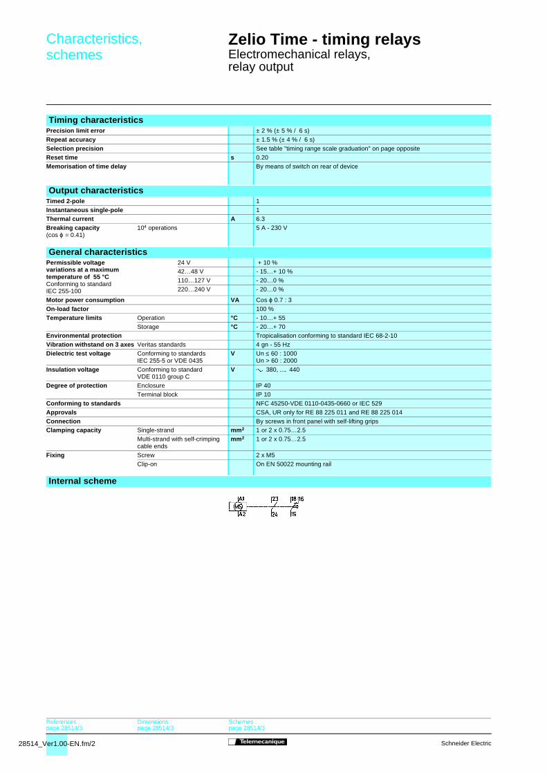
28514_Ver1.00-EN.fm/2 Schneider Electric
Characteristics,schemes
Zelio Time - timing relays 0
Electromechanical relays,relay output
Timing characteristicsPrecision limit error ± 2 % (± 5 % / 6 s)
Repeat accuracy ± 1.5 % (± 4 % / 6 s)
Selection precision See table "timing range scale graduation" on page opposite
Reset time s 0.20
Memorisation of time delay By means of switch on rear of device
Output characteristicsTimed 2-pole 1
Instantaneous single-pole 1Thermal current A 6.3
Breaking capacity(cos ϕ = 0.41)
104 operations 5 A - 230 V
General characteristicsPermissible voltage variations at a maximum temperature of 55 °CConforming to standard IEC 255-100
24 V + 10 %42…48 V - 15…+ 10 %
110…127 V - 20…0 %
220…240 V - 20…0 %
Motor power consumption VA Cos ϕ 0.7 : 3
On-load factor 100 %
Temperature limits Operation °C - 10…+ 55
Storage °C - 20…+ 70Environmental protection Tropicalisation conforming to standard IEC 68-2-10
Vibration withstand on 3 axes Veritas standards 4 gn - 55 Hz
Dielectric test voltage Conforming to standardsIEC 255-5 or VDE 0435
V Un ≤ 60 : 1000Un > 60 : 2000
Insulation voltage Conforming to standard VDE 0110 group C
V 380, 440
Degree of protection Enclosure IP 40
Terminal block IP 10
Conforming to standards NFC 45250-VDE 0110-0435-0660 or IEC 529
Approvals CSA, UR only for RE 88 225 011 and RE 88 225 014
Connection By screws in front panel with self-lifting gripsClamping capacity Single-strand mm2 1 or 2 x 0.75…2.5
Multi-strand with self-crimping cable ends
mm2 1 or 2 x 0.75…2.5
Fixing Screw 2 x M5
Clip-on On EN 50022 mounting rail
Internal scheme
References :page 28514/3
Dimensions :page 28514/3
Schemes :page 28514/3
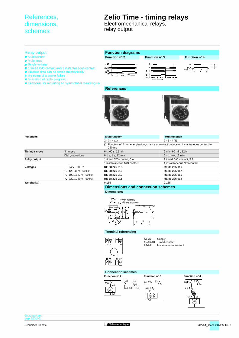
28514_Ver1.00-EN.fm/3Schneider Electric
References,dimensions,schemes
Zelio Time - timing relays 0
Electromechanical relays,relay output
Relay output Multifunction Multirange Single voltage 1 timed C/O contact and 1 instantaneous contact Elapsed time can be saved mechanicallyin the event of a power failure Indication of cycle progress Enclosure for mounting on symmetrical mounting rail
Function diagramsFunction n° 2 Function n° 3 Function n° 4
References
Functions Multifunction Multifunction 2 - 3 - 4 (1) 2 - 3 - 4 (1)(1) Function n° 4 : on energisation, chance of contact bounce on instantaneous contact for
250 ms
Timing ranges 3 ranges 6 s, 60 s, 12 min 6 min, 60 min, 12 h
Dial graduations 0.1 s, 1 s, 12 min 6s, 1 min, 12 min
Relay output 1 timed C/O contact, 5 A 1 timed C/O contact, 5 A1 instantaneous N/O contact 1 instantaneous N/O contact
Voltages 24 V - 50 Hz RE 88 225 013 RE 88 225 01642…48 V - 50 Hz RE 88 225 019 RE 88 225 017100…127 V - 50 Hz RE 88 225 012 RE 88 225 015220…240 V - 50 Hz RE 88 225 011 RE 88 225 014
Weight (kg) 0.185 0.185
Dimensions and connection schemesDimensions
Terminal referencing
A1-A2 Supply15-16-18 Timed contact23-24 Instantaneous contact
Connection schemesFunction n° 2 Function n° 3 Function n° 4
5611
83
5611
83
With memoryWithout memory
MAA1
A2
23 15
24 18 16MS
MI
A1
A2
MS
AR
2324
23
15
18
MI
16
MS
AR
24
Characteristics :page 28514/2