XCell Furion 450 Assembly Manual R1 - RVMHC - Websitervmhc.com/manuals/ma/furion450manual2.pdf ·...
89
Created: 8/27/2008 Copyright Miniature Aircraft US This document may not be distributed without permission of Miniature Aircraft USA X-Cell Furion 450 Assembly Manual Version 1.1 Last Revised: 08/10/2008
Transcript of XCell Furion 450 Assembly Manual R1 - RVMHC - Websitervmhc.com/manuals/ma/furion450manual2.pdf ·...
Created: 8/27/2008 Copyright Miniature Aircraft US This document may not be distributed without permission of Miniature Aircraft USA
X-Cell Furion 450 Assembly Manual
Version 1.1 Last Revised: 08/10/2008

X-Cell Furion 450 Assembly Manual
Page 2 of 89 Copyright Miniature Aircraft USA Created: 8/27/2008 This document may not be distributed without permission of Miniature Aircraft USA
For More Information contact:
Miniature Aircraft USA 31713 Long Acres Drive Sorrento, FL 32776 USA Phone 352-383-3201 Fax 352-383-3204 Email: [email protected]

X-Cell Furion 450 Assembly Manual
Created: 8/27/2008 Copyright Miniature Aircraft USA Page 3 of 89 This document may not be distributed without permission of Miniature Aircraft USA
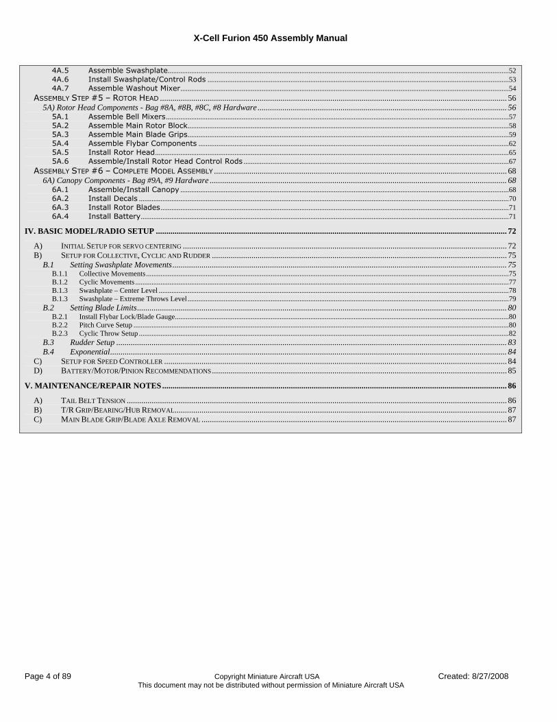
Table of Contents
REVISIONS TO THIS MANUAL ................................................................................................................................................................................5 ERRATA .........................................................................................................................................................................................................................5 I. KIT INTRODUCTION ..............................................................................................................................................................................................6
R/C HELICOPTER SAFETY ..............................................................................................................................................................................................6 GUIDELINES FOR SAFE R/C HELICOPTER FLIGHT............................................................................................................................................................6 X-CELL LIMITED WARRANTY ......................................................................................................................................................................................7 WARRANTY PROCEDURES..............................................................................................................................................................................................7 X-CELL FURION 450 WARRANTY REGISTRATION...........................................................................................................................................................7
II. KIT PREREQUISITES ............................................................................................................................................................................................8 SUPPLIES NEEDED FOR ASSEMBLY.................................................................................................................................................................................8
Adhesives Used ........................................................................................................................................................................................................8 TOOLS NEEDED FOR ASSEMBLY.....................................................................................................................................................................................9 ADDITIONAL COMPONENTS NEEDED (AS SHOWN OR COMPATIBLE) .................................................................................................................................9 DOCUMENTATION........................................................................................................................................................................................................10
III. KIT ASSEMBLY PROCESS ................................................................................................................................................................................11 ASSEMBLY TIPS...........................................................................................................................................................................................................11 FASTENER GUIDE ........................................................................................................................................................................................................11 ASSEMBLY COMPONENTS – UNBAGGED PARTS ............................................................................................................................................................13 LOCATE CARBON FIBER PARTS BAG ............................................................................................................................................................................14
Carbon Fiber Parts - Bag #1 .................................................................................................................................................................................14 ASSEMBLY STEP #1 – CHASSIS...............................................................................................................................................................................15
1A) Frame Components - Bags #2A, #2B, #2 Hardware .......................................................................................................................................15 1A.1 - Assemble Tail Boom Clamp/Pulleys........................................................................................................................................................................16 1B.1 - Assemble Left Frame Components .........................................................................................................................................................................18 1C.1 – Install Right Frame/Landing Gear ..........................................................................................................................................................................21 1D.1 – Install Pitch/Aileron Servos ......................................................................................................................................................................................23
ASSEMBLY STEP #2 – PRIMARY DRIVE ...................................................................................................................................................................24 2A) Drive Train Components - Bag #3A, #3 Hardware.........................................................................................................................................24
2A.1 - Assemble T/R Pulley .....................................................................................................................................................................................................25 2B.1 - Assemble Main Gear .....................................................................................................................................................................................................26 2C.1 – Install Drive System ....................................................................................................................................................................................................27 2D.1 – Install Motor ....................................................................................................................................................................................................................28
LOCATE LONG PARTS BAG ..........................................................................................................................................................................................29 Long Parts - Bag #4...............................................................................................................................................................................................29
ASSEMBLY STEP #3 – TAIL ROTOR/TAIL BOOM.....................................................................................................................................................30 3A) Tail Rotor Components - Bag #5A, 5B, 5C, #5 Hardware ..............................................................................................................................30
3A.1 - Assemble T/R Fin ...........................................................................................................................................................................................................31 3A.2 – Assemble/Install T/R Bellcrank................................................................................................................................................................................32 3A.3 – Assemble/Install Tail Boom ......................................................................................................................................................................................33 3A.4 – Assemble T/R Transmission ......................................................................................................................................................................................34 3A.5 – Set T/R Belt Tension ....................................................................................................................................................................................................35 3A.6 – Assemble T/R Pitch Change Mechanism ..............................................................................................................................................................36 3A.7 – Assemble T/R Hub ........................................................................................................................................................................................................38 3A.8 – Install T/R Pitch Change Mechanism.....................................................................................................................................................................40 3A.9 – Install Tail Rotor Assembly........................................................................................................................................................................................40
3B) Tail Rotor Control - Bag #6A, #6 Hardware...................................................................................................................................................41 3B.1 Install T/R Servo................................................................................................................................................................................................................41 3B.2 Assemble T/R Pushrod ....................................................................................................................................................................................................43 3B.3 Assemble/Install Tail Boom Supports .......................................................................................................................................................................44
ASSEMBLY STEP #4 – CONTROL SYSTEMS .............................................................................................................................................................46 4A) Electronics Installation/Main Control Components - Bag #7A, #7B, #7 Hardware .......................................................................................46
4A.1 Install Elevator Servo.............................................................................................................................................................................................47 4A.2 Install Electronics.....................................................................................................................................................................................................47 4A.3 Install Servo Arms...................................................................................................................................................................................................50 4A.4 Assemble Cyclic Control Rods.............................................................................................................................................................................51
X-Cell Furion 450 Assembly Manual
Page 4 of 89 Copyright Miniature Aircraft USA Created: 8/27/2008 This document may not be distributed without permission of Miniature Aircraft USA
4A.5 Assemble Swashplate.............................................................................................................................................................................................52 4A.6 Install Swashplate/Control Rods .......................................................................................................................................................................53 4A.7 Assemble Washout Mixer......................................................................................................................................................................................54
ASSEMBLY STEP #5 – ROTOR HEAD ....................................................................................................................................................................... 56 5A) Rotor Head Components - Bag #8A, #8B, #8C, #8 Hardware........................................................................................................................ 56
5A.1 Assemble Bell Mixers..............................................................................................................................................................................................57 5A.2 Assemble Main Rotor Block..................................................................................................................................................................................58 5A.3 Assemble Main Blade Grips..................................................................................................................................................................................59 5A.4 Assemble Flybar Components ............................................................................................................................................................................62 5A.5 Install Rotor Head....................................................................................................................................................................................................65 5A.6 Assemble/Install Rotor Head Control Rods ...................................................................................................................................................67
ASSEMBLY STEP #6 – COMPLETE MODEL ASSEMBLY ............................................................................................................................................. 68 6A) Canopy Components - Bag #9A, #9 Hardware ............................................................................................................................................... 68
6A.1 Assemble/Install Canopy ......................................................................................................................................................................................68 6A.2 Install Decals .............................................................................................................................................................................................................70 6A.3 Install Rotor Blades.................................................................................................................................................................................................71 6A.4 Install Battery............................................................................................................................................................................................................71
IV. BASIC MODEL/RADIO SETUP ......................................................................................................................................................................... 72 A) INITIAL SETUP FOR SERVO CENTERING ............................................................................................................................................................ 72 B) SETUP FOR COLLECTIVE, CYCLIC AND RUDDER .............................................................................................................................................. 75
B.1 Setting Swashplate Movements................................................................................................................................................................. 75 B.1.1 Collective Movements.........................................................................................................................................................................................................75 B.1.2 Cyclic Movements ...............................................................................................................................................................................................................77 B.1.3 Swashplate – Center Level ..................................................................................................................................................................................................78 B.1.3 Swashplate – Extreme Throws Level ..................................................................................................................................................................................79
B.2 Setting Blade Limits.................................................................................................................................................................................. 80 B.2.1 Install Flybar Lock/Blade Gauge.........................................................................................................................................................................................80 B.2.2 Pitch Curve Setup ................................................................................................................................................................................................................80 B.2.3 Cyclic Throw Setup .............................................................................................................................................................................................................82
B.3 Rudder Setup ............................................................................................................................................................................................ 83 B.4 Exponential............................................................................................................................................................................................... 84
C) SETUP FOR SPEED CONTROLLER ..................................................................................................................................................................... 84 D) BATTERY/MOTOR/PINION RECOMMENDATIONS.............................................................................................................................................. 85
V. MAINTENANCE/REPAIR NOTES...................................................................................................................................................................... 86 A) TAIL BELT TENSION ....................................................................................................................................................................................... 86 B) T/R GRIP/BEARING/HUB REMOVAL................................................................................................................................................................ 87 C) MAIN BLADE GRIP/BLADE AXLE REMOVAL ................................................................................................................................................... 87
X-Cell Furion 450 Assembly Manual
Created: 8/27/2008 Copyright Miniature Aircraft USA Page 5 of 89 This document may not be distributed without permission of Miniature Aircraft USA
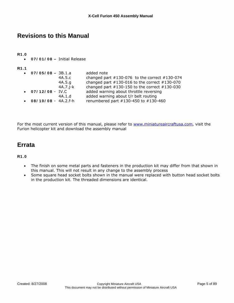
Revisions to this Manual
R1.0
• 07/01/08 – Initial Release R1.1
• 07/05/08 – 3B.1.a added note 4A.5.c changed part #130-076 to the correct #130-074 4A.5.g changed part #130-016 to the correct #130-070 4A.7.j-k changed part #130-150 to the correct #130-030
• 07/12/08 - IV.C added warning about throttle reversing 4A.1.d added warning about t/r belt routing
• 08/10/08 - 4A.2.f-h renumbered part #130-450 to #130-460
For the most current version of this manual, please refer to www.miniatureaircraftusa.com, visit the Furion helicopter kit and download the assembly manual
Errata R1.0
• The finish on some metal parts and fasteners in the production kit may differ from that shown in this manual. This will not result in any change to the assembly process
• Some square head socket bolts shown in the manual were replaced with button head socket bolts in the production kit. The threaded dimensions are identical.
X-Cell Furion 450 Assembly Manual
Page 6 of 89 Copyright Miniature Aircraft USA Created: 8/27/2008 This document may not be distributed without permission of Miniature Aircraft USA
I. Kit Introduction
R/C Helicopter Safety A radio controlled model helicopter is a technically complex device that must be built and operated with care. It is also a fascinating and challenging part of the R/C sport, the mastery of which is very rewarding. A model helicopter must be built exactly in accordance with the building instructions. The kit manufacturer has spent much time and effort refining his product to make it reliable in operation and easy to build. The essentially bolt together construction can proceed quite rapidly, giving the builder a strong sense of accomplishment that encourages hasty progress from one construction phase to the next, so that the completed model can be more quickly seen and enjoyed. It is essential to recognize and guard against this tendency. Follow building instructions exactly. Vibration and stress levels are high and all fasteners and attachments must be secure for safe operation. Note that this is the first use of the word SAFETY in these comments. Previously the kit manufacturer’s efforts to ensure reliable operation were mentioned. That is ALL that he can do. Safe operation is the responsibility of the builder/flyer and starts with careful construction and continues with selection and installation of reliable radio equipment and engine. The need for safety is nowhere greater than at the flying field. A number of guidelines for safe flight have been developed by experienced flyers and are set down here. It is urged that they be read, understood and followed.
Guidelines for Safe R/C Helicopter Flight
• Fly only at approved flying fields and obey field regulations. • Follow frequency control procedures. Interference can be dangerous to all. • Know your radio. Check all transmitter functions before each flight. • Be aware that rotating blades are very dangerous and can cause serious injury. • Never fly near or above spectators or other modelers. • If a beginner, get help trimming the model first and flight training later. • Don’t “track” the main blades by holding the tail boom. This is a temptation to builders who cannot
hover yet and is very dangerous. • Follow all recommended maintenance procedures for model, radio and engine.
WARNING! This helicopter is not a toy, but a complex flying machine that must be assembled with care by a responsible individual. Failure to exert care in assembly, or radio or accessory installation, may result in a model incapable of safe flight or ground operation. Rotating components are an ever present danger and source of injury to operators and spectators. Since the manufacturer and his agents have no control over the proper assembly and operation of his products, no responsibility or liability can be assumed for their use.

X-Cell Furion 450 Assembly Manual
Created: 8/27/2008 Copyright Miniature Aircraft USA Page 7 of 89 This document may not be distributed without permission of Miniature Aircraft USA
X-CELL Limited Warranty The warranty covers defects in material or workmanship or missing components to the original purchaser for 30 days from the date of purchase. Miniature Aircraft, USA will replace or repair, at our discretion, the defective or missing component. Defective components must be returned to us prior to replacement. Any part, which has been improperly installed, abused, crash damaged or altered by unauthorized agencies, is not covered. Under no circumstances will the buyer be entitled to consequential or incidental damages. The components used in this kit are made form special materials designed for special applications and design strengths. We recommend that all replacement parts be original parts manufactured by Miniature Aircraft, USA, to ensure proper and safe operation of your model. Any part used which was manufactured by any firm other than Miniature Aircraft, USA, VOIDS all warrantees of this product by Miniature Aircraft, USA.
Warranty Procedures Mail all warranty information within 15 days of original purchase date. If service is required, send the component in question (if not missing) together with a photocopy of your bill of sale and an accurate description of the problem and part. Ship components fully insured and prepaid. Miniature Aircraft, USA is not responsible for any shipping damages. We will, at our discretion, notify you of any costs involved, or ship it COD. You are required to pay all postage, shipping and insurance charges.
X-Cell Furion 450 Warranty Registration Please print or type, filling in the information listed below and mail immediately Model No:____________ Serial No:____________ Price paid:___________________
Owners name:______________________________ Age_______________________
Address:____________________________________ Phone:___________________
City:_______________________ State:____________ Zip:___________________
Purchased from: ________________________________________________________
Dealer’s address ________________________________________________________
Comments: ____________________________________________________________ ______________________________________________________________________ _________________________________________________________________________ _________________________________________________________________________ _________________________________________________________________________
MINIATURE AIRCRAFT USA 31713 Long Acres Drive Sorrento, FL 32776 USA
Phone (352) 383-3201 FAX (352) 383-3204
X-Cell Furion 450 Assembly Manual
Page 8 of 89 Copyright Miniature Aircraft USA Created: 8/27/2008 This document may not be distributed without permission of Miniature Aircraft USA
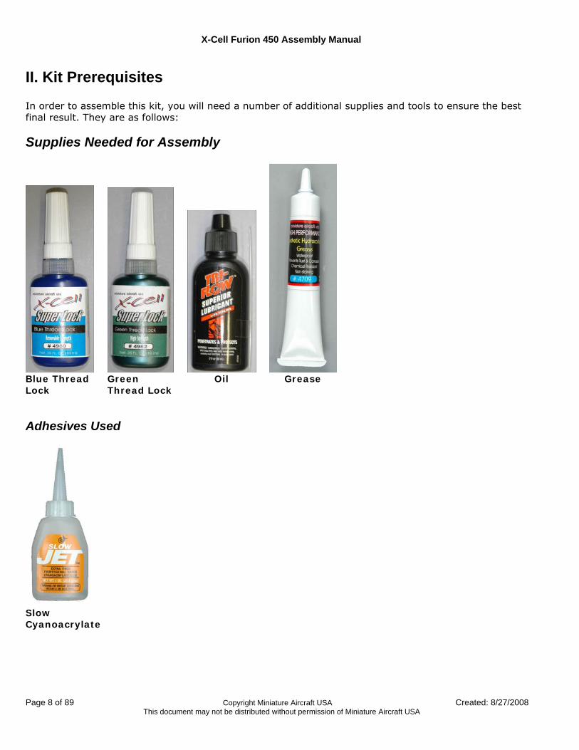
II. Kit Prerequisites In order to assemble this kit, you will need a number of additional supplies and tools to ensure the best final result. They are as follows:
Supplies Needed for Assembly
Blue Thread Lock
Green Thread Lock
Oil Grease
Adhesives Used
Slow Cyanoacrylate
X-Cell Furion 450 Assembly Manual
Created: 8/27/2008 Copyright Miniature Aircraft USA Page 9 of 89 This document may not be distributed without permission of Miniature Aircraft USA
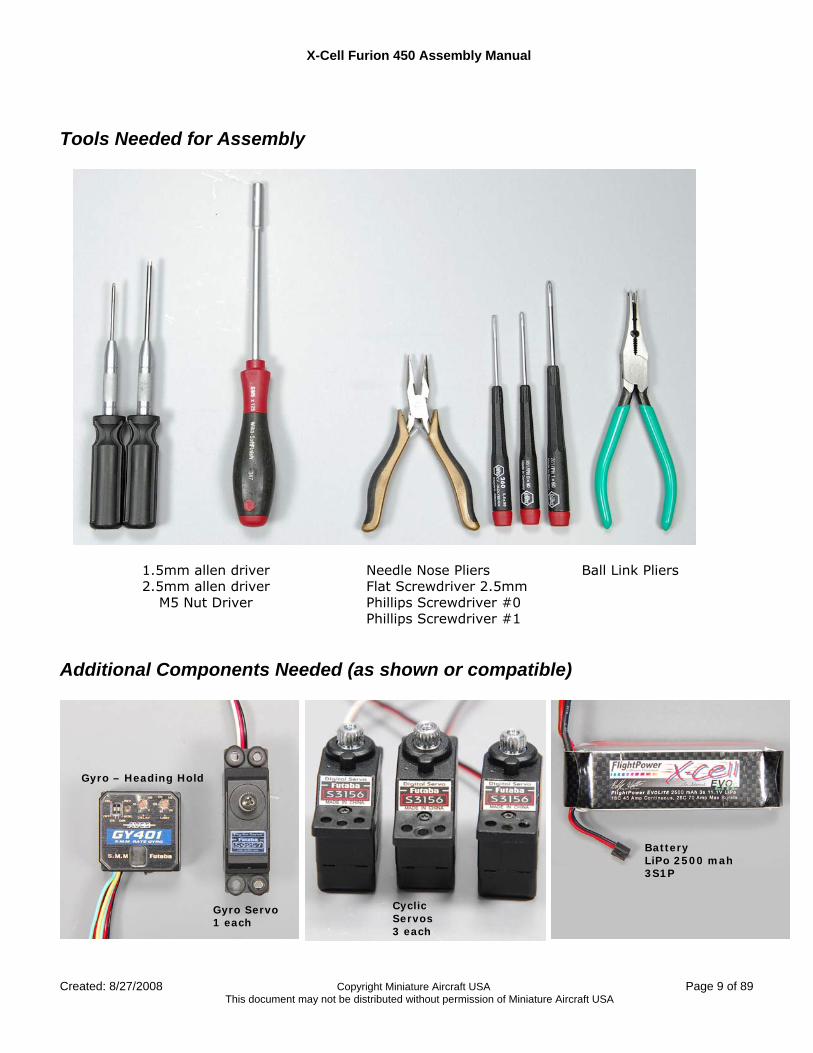
Tools Needed for Assembly
1.5mm allen driver 2.5mm allen driver
M5 Nut Driver
Needle Nose Pliers Flat Screwdriver 2.5mm Phillips Screwdriver #0 Phillips Screwdriver #1
Ball Link Pliers
Additional Components Needed (as shown or compatible)
Gyro – Heading Hold
Gyro Servo 1 each
Cyclic Servos 3 each
Battery LiPo 2500 mah 3S1P

X-Cell Furion 450 Assembly Manual
Page 10 of 89 Copyright Miniature Aircraft USA Created: 8/27/2008 This document may not be distributed without permission of Miniature Aircraft USA
Documentation
The most recent version of all of the documentation can be found on the website: www.miniatureaircraftusa.com
Receiver
Minimum 45 amp ESC With BEC Or a separate BEC is required
Motor
Rotor Blades SAB 320-325mm
Paddle/Pitch gauge tools
X-Cell Furion 450 Assembly Manual
Created: 8/27/2008 Copyright Miniature Aircraft USA Page 11 of 89 This document may not be distributed without permission of Miniature Aircraft USA
III. Kit Assembly Process
Assembly Tips
1. Please note that this assembly manual consists of a photographic journal of the steps necessary to construct this helicopter. The builder is encouraged to pay close attention to the "building notes" and other details noted in the pictures and to carefully review all the photo’s in a given step. The placement of a given part may be better understood when viewing another view of the assembly.
2. Follow the order of assembly. The instructions have been organized into major sections and have been developed in such a way that each step builds upon the work done in the previous step. Changing the order of assembly may result in unnecessary steps
3. The photos in this manual are organized within each step to correspond with the order of assembly. The sequence of the photos within a step is from top to bottom and from left to right.
4. Clean all metal parts: All of the steel parts in this kit are coated with a lubricant to prevent them from rusting. This coating can interfere with the adhesives and thread locks needed for assembly. Use a solvent such as alcohol or acetone to clean the various metal parts, especially threads
5. Use only the formula of thread lock as indicated. Model helicopters are subject to vibration and failing to use the correct formula of thread lock on any non-locking assembly may result in a part becoming loose or falling off.
6. Sand sharp edges on any frame plate that Velcro® or wires may rub against to prevent them from being damaged over time by vibration
7. Make sure every bearing runs smoothly after component assembly. If it does not find out why. A rough running bearing will fail prematurely.
8. As a general rule any bolt that threads into a metal part should have thread lock applied and any screw or bolt that threads into a plastic part should have thick (ONLY) Cyanoacrylate adhesive applied
9. Assembly sections contain the following content: a. The contents of each bag b. An overview of part relationships c. Assembly overview
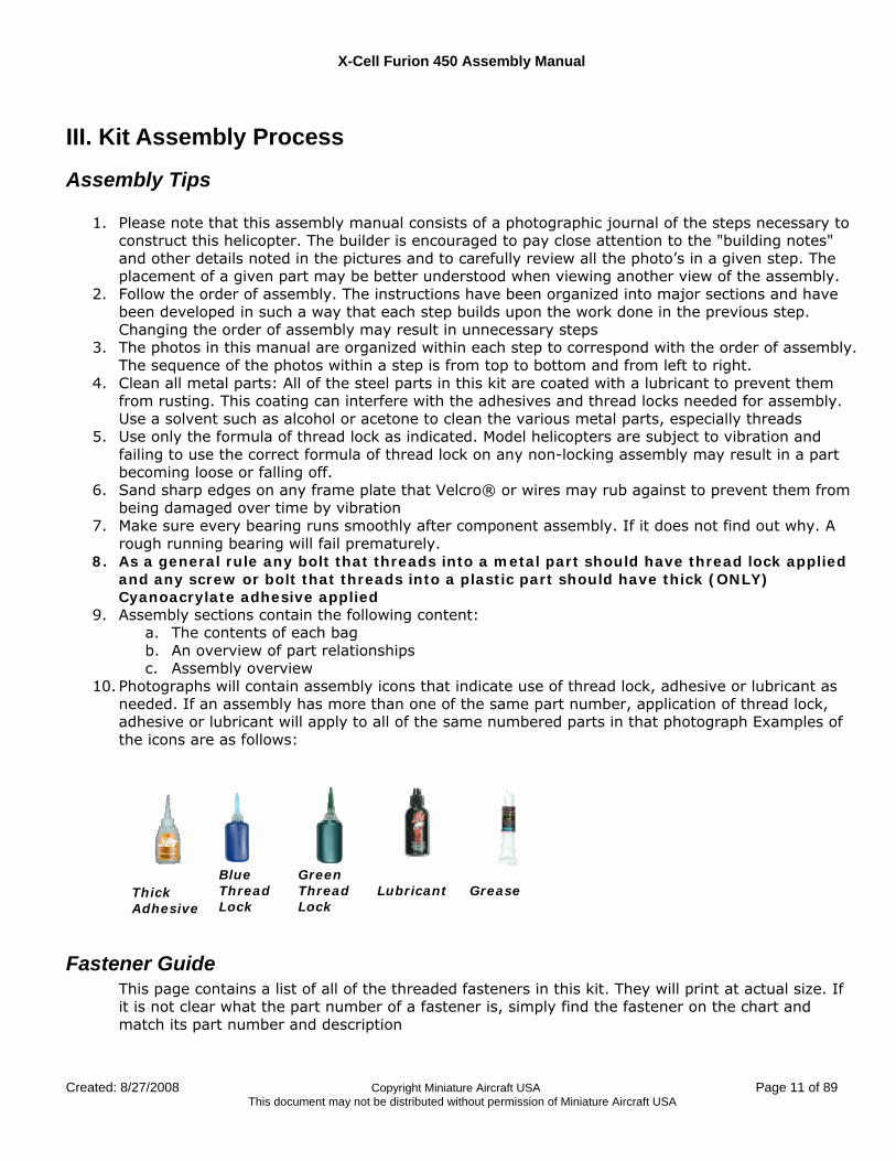
10. Photographs will contain assembly icons that indicate use of thread lock, adhesive or lubricant as needed. If an assembly has more than one of the same part number, application of thread lock, adhesive or lubricant will apply to all of the same numbered parts in that photograph Examples of the icons are as follows:
Thick Adhesive
Blue Thread Lock
Green Thread Lock
Lubricant
Grease
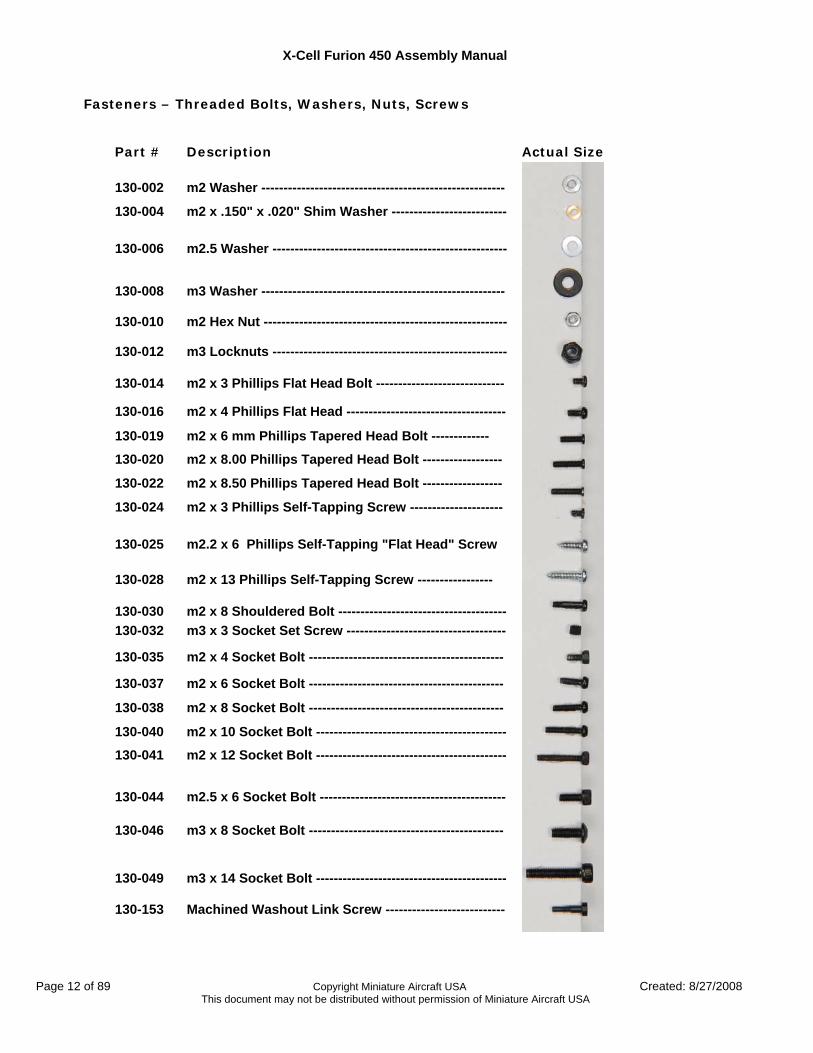
Fastener Guide This page contains a list of all of the threaded fasteners in this kit. They will print at actual size. If it is not clear what the part number of a fastener is, simply find the fastener on the chart and match its part number and description
X-Cell Furion 450 Assembly Manual
Page 12 of 89 Copyright Miniature Aircraft USA Created: 8/27/2008 This document may not be distributed without permission of Miniature Aircraft USA
Fasteners – Threaded Bolts, Washers, Nuts, Screws
Part # Description Actual Size
130-002 m2 Washer -------------------------------------------------------
130-004 m2 x .150" x .020" Shim Washer --------------------------
130-006 m2.5 Washer -----------------------------------------------------
130-008 m3 Washer -------------------------------------------------------
130-010 m2 Hex Nut -------------------------------------------------------
130-012 m3 Locknuts -----------------------------------------------------
130-014 m2 x 3 Phillips Flat Head Bolt -----------------------------
130-016 m2 x 4 Phillips Flat Head ------------------------------------
130-019 m2 x 6 mm Phillips Tapered Head Bolt -------------
130-020 m2 x 8.00 Phillips Tapered Head Bolt ------------------
130-022 m2 x 8.50 Phillips Tapered Head Bolt ------------------
130-024 m2 x 3 Phillips Self-Tapping Screw ---------------------
130-025 m2.2 x 6 Phillips Self-Tapping "Flat Head" Screw
130-028 m2 x 13 Phillips Self-Tapping Screw -----------------
130-030 m2 x 8 Shouldered Bolt -------------------------------------- 130-032 m3 x 3 Socket Set Screw ------------------------------------
130-035 m2 x 4 Socket Bolt --------------------------------------------
130-037 m2 x 6 Socket Bolt --------------------------------------------
130-038 m2 x 8 Socket Bolt --------------------------------------------
130-040 m2 x 10 Socket Bolt -------------------------------------------
130-041 m2 x 12 Socket Bolt -------------------------------------------
130-044 m2.5 x 6 Socket Bolt ------------------------------------------
130-046 m3 x 8 Socket Bolt --------------------------------------------
130-049 m3 x 14 Socket Bolt -------------------------------------------
130-153 Machined Washout Link Screw ---------------------------
X-Cell Furion 450 Assembly Manual
Created: 8/27/2008 Copyright Miniature Aircraft USA Page 13 of 89 This document may not be distributed without permission of Miniature Aircraft USA
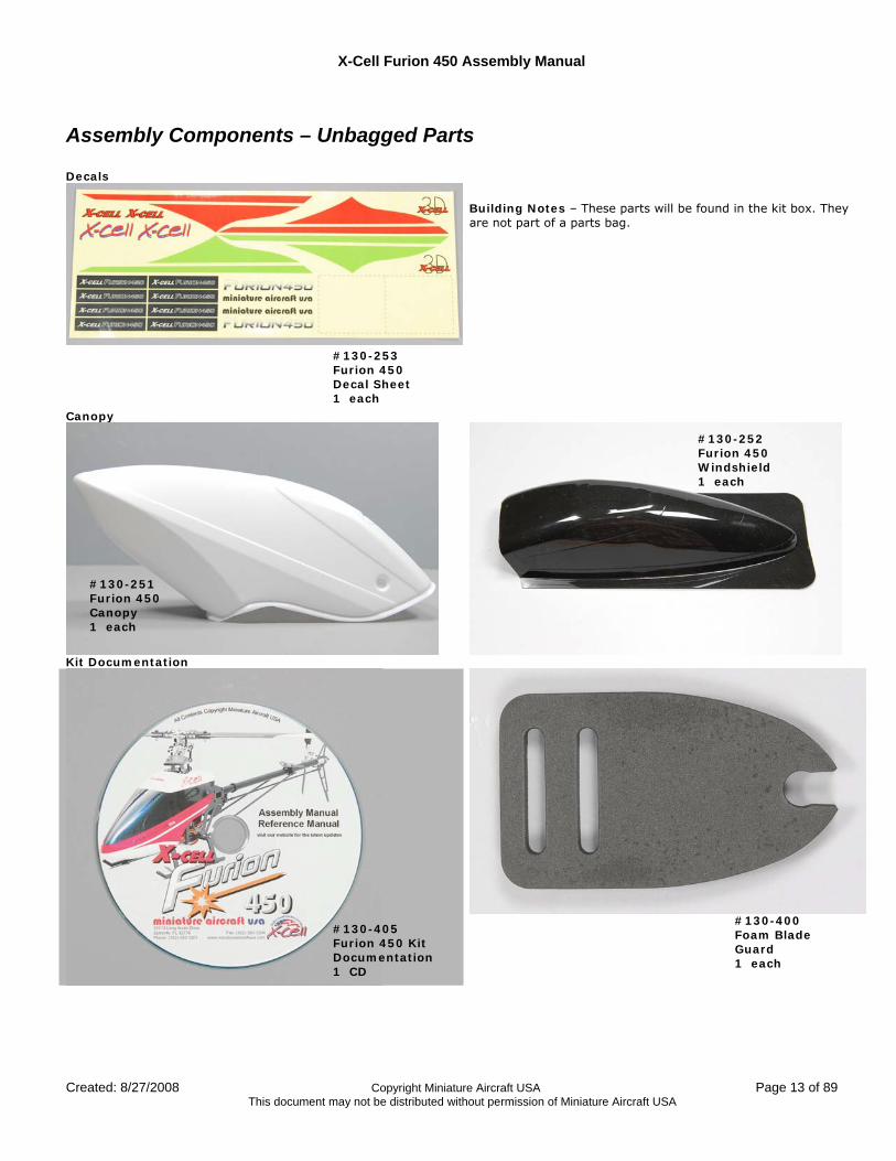
Assembly Components – Unbagged Parts Decals
Building Notes – These parts will be found in the kit box. They are not part of a parts bag.
Canopy
Kit Documentation
#130-251 Furion 450 Canopy 1 each
#130-253 Furion 450 Decal Sheet 1 each
#130-252 Furion 450 Windshield 1 each
#130-405 Furion 450 Kit Documentation 1 CD
#130-400 Foam Blade Guard 1 each
X-Cell Furion 450 Assembly Manual
Page 14 of 89 Copyright Miniature Aircraft USA Created: 8/27/2008 This document may not be distributed without permission of Miniature Aircraft USA
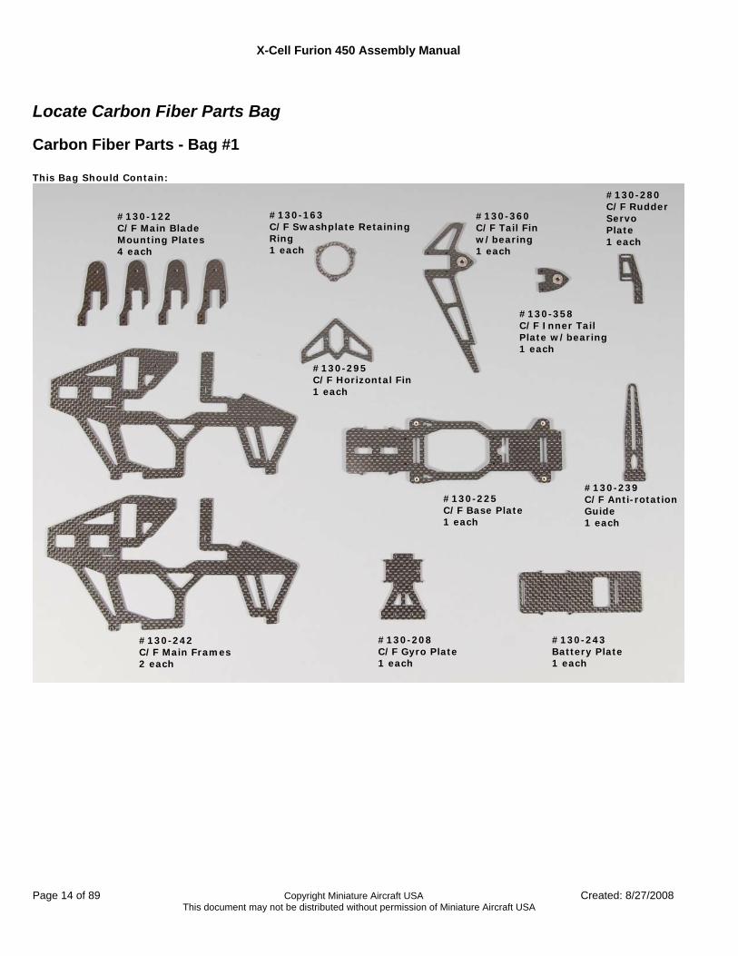
Locate Carbon Fiber Parts Bag
Carbon Fiber Parts - Bag #1 This Bag Should Contain:
#130-242 C/F Main Frames 2 each
#130-122 C/F Main Blade Mounting Plates 4 each
#130-243 Battery Plate 1 each
#130-239 C/F Anti-rotation Guide 1 each
#130-280 C/F Rudder Servo Plate 1 each
#130-163 C/F Swashplate Retaining Ring 1 each
#130-208 C/F Gyro Plate 1 each
#130-225 C/F Base Plate 1 each
#130-295 C/F Horizontal Fin 1 each
#130-358 C/F Inner Tail Plate w/bearing 1 each
#130-360 C/F Tail Fin w/bearing 1 each
X-Cell Furion 450 Assembly Manual
Created: 8/27/2008 Copyright Miniature Aircraft USA Page 15 of 89 This document may not be distributed without permission of Miniature Aircraft USA
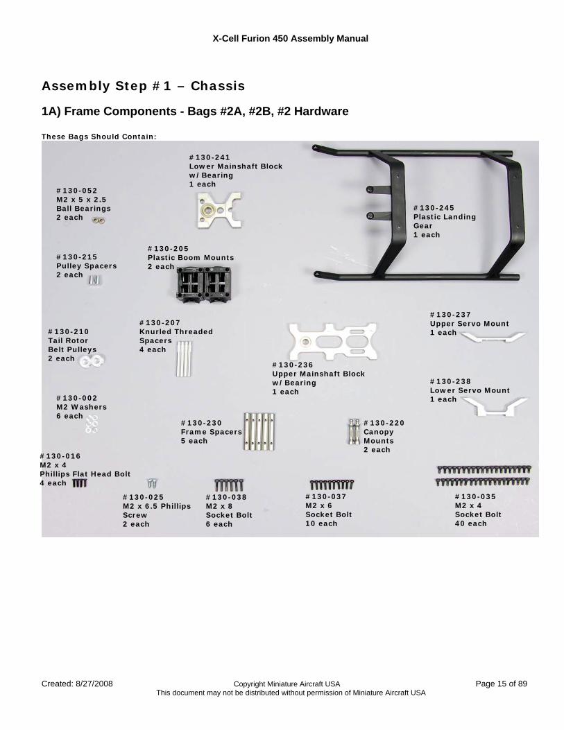
Assembly Step #1 – Chassis
1A) Frame Components - Bags #2A, #2B, #2 Hardware These Bags Should Contain:
#130-245 Plastic Landing Gear 1 each
#130-052 M2 x 5 x 2.5 Ball Bearings 2 each
#130-205 Plastic Boom Mounts 2 each
#130-207 Knurled Threaded Spacers 4 each
#130-210 Tail Rotor Belt Pulleys 2 each
#130-215 Pulley Spacers 2 each
#130-236 Upper Mainshaft Block w/Bearing 1 each
#130-238 Lower Servo Mount 1 each
#130-237 Upper Servo Mount 1 each
#130-241 Lower Mainshaft Block w/Bearing 1 each
#130-220 Canopy Mounts 2 each
#130-230 Frame Spacers 5 each
#130-002 M2 Washers 6 each
#130-016 M2 x 4 Phillips Flat Head Bolt 4 each
#130-025 M2 x 6.5 Phillips Screw 2 each
#130-038 M2 x 8 Socket Bolt 6 each
#130-037 M2 x 6 Socket Bolt 10 each
#130-035 M2 x 4 Socket Bolt 40 each
X-Cell Furion 450 Assembly Manual
Page 16 of 89 Copyright Miniature Aircraft USA Created: 8/27/2008 This document may not be distributed without permission of Miniature Aircraft USA
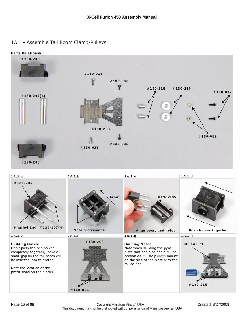
1A.1 - Assemble Tail Boom Clamp/Pulleys Parts Relationship
1A.1.a 1A.1.b 1A.1.c 1A.1.d
1A.1.e 1A.1.f 1A.1.g 1A.1.h Building Notes: Don’t push the two halves completely together, leave a small gap as the tail boom will be inserted into this later Note the location of the protrusions on the blocks
Building Notes: Note when building the gyro plate that one side has a milled section on it. The pulleys mount on the side of the plate with the milled flat.
#130-205
#130-205
#130-207(4)
#130-208
#130-025
#130-025
#130-035
#130-035
#130-215 #130-210
#130-052
#130-037
#130-205
#130-207(4) Knurled End
Front #130-205
Push halves together Align posts and holes Note protrusions
#130-208
#130-035
#130-215
Milled Flat
X-Cell Furion 450 Assembly Manual
Created: 8/27/2008 Copyright Miniature Aircraft USA Page 17 of 89 This document may not be distributed without permission of Miniature Aircraft USA
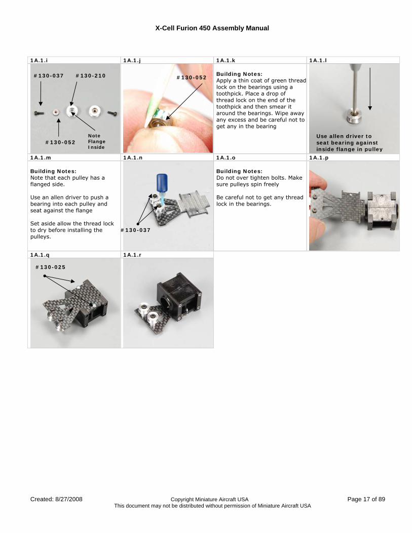
1A.1.i 1A.1.j 1A.1.k 1A.1.l
Building Notes: Apply a thin coat of green thread lock on the bearings using a toothpick. Place a drop of thread lock on the end of the toothpick and then smear it around the bearings. Wipe away any excess and be careful not to get any in the bearing
1A.1.m 1A.1.n 1A.1.o 1A.1.p Building Notes: Note that each pulley has a flanged side. Use an allen driver to push a bearing into each pulley and seat against the flange Set aside allow the thread lock to dry before installing the pulleys.
Building Notes: Do not over tighten bolts. Make sure pulleys spin freely Be careful not to get any thread lock in the bearings.
1A.1.q 1A.1.r
#130-037
#130-052
#130-210
Note Flange Inside
#130-052
Use allen driver to seat bearing against inside flange in pulley
#130-037
#130-025
X-Cell Furion 450 Assembly Manual
Page 18 of 89 Copyright Miniature Aircraft USA Created: 8/27/2008 This document may not be distributed without permission of Miniature Aircraft USA
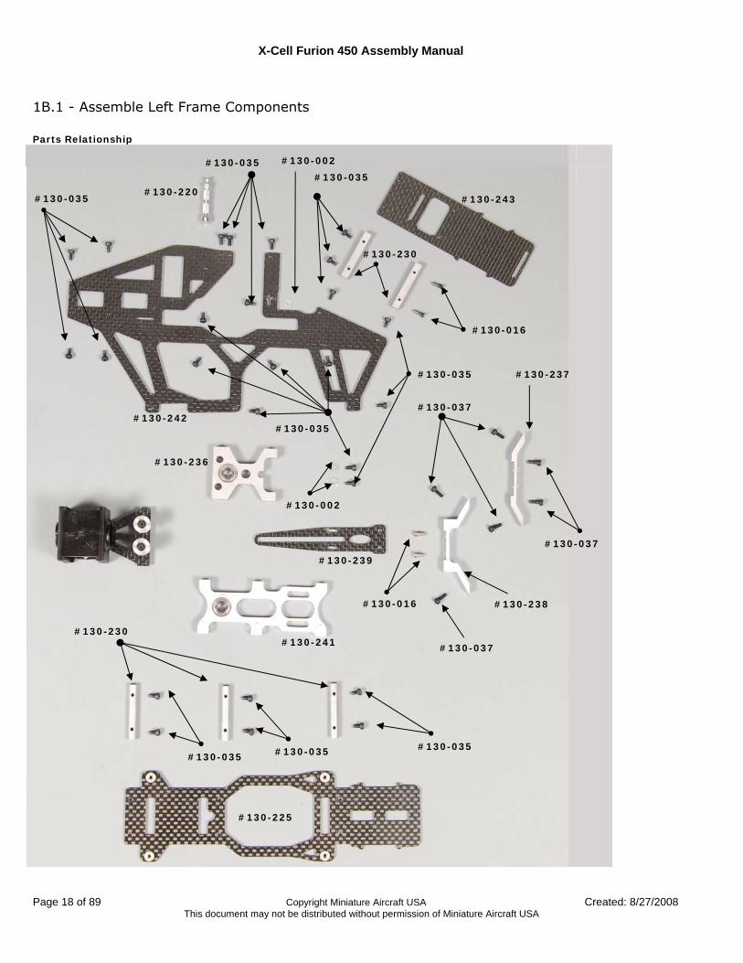
1B.1 - Assemble Left Frame Components Parts Relationship
#130-220
#130-035
#130-035 #130-242
#130-243
#130-230
#130-035
#130-016
#130-037
#130-236
#130-239
#130-241
#130-225
#130-230
#130-035 #130-035 #130-035
#130-237
#130-002
#130-037
#130-238 #130-016
#130-002
#130-035 #130-035
#130-037
X-Cell Furion 450 Assembly Manual
Created: 8/27/2008 Copyright Miniature Aircraft USA Page 19 of 89 This document may not be distributed without permission of Miniature Aircraft USA
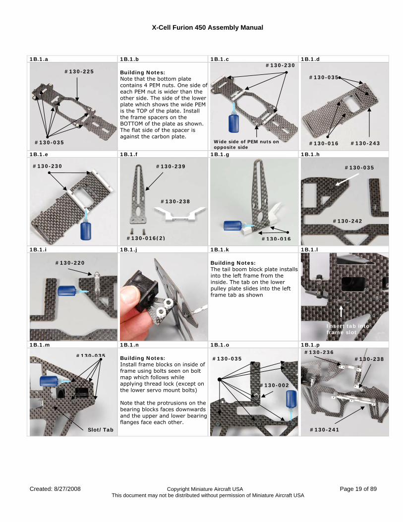
1B.1.a 1B.1.b 1B.1.c 1B.1.d
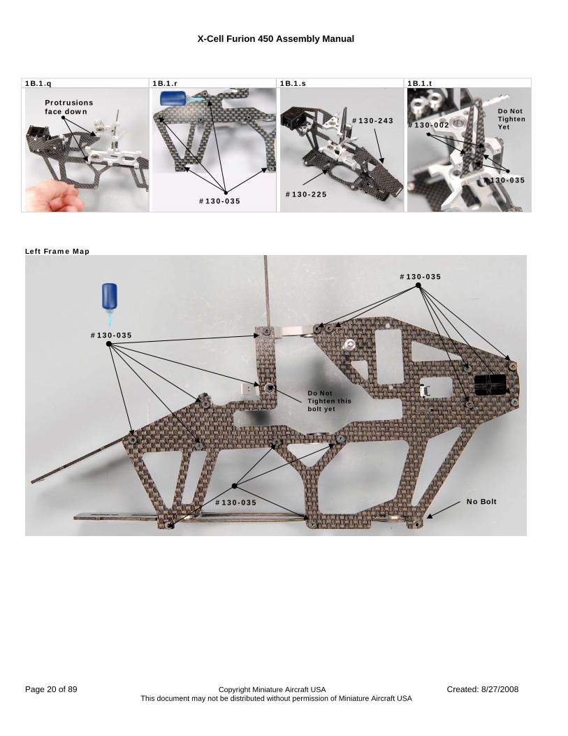
Building Notes: Note that the bottom plate contains 4 PEM nuts. One side of each PEM nut is wider than the other side. The side of the lower plate which shows the wide PEM is the TOP of the plate. Install the frame spacers on the BOTTOM of the plate as shown. The flat side of the spacer is against the carbon plate.
1B.1.e 1B.1.f 1B.1.g 1B.1.h
1B.1.i 1B.1.j 1B.1.k 1B.1.l Building Notes: The tail boom block plate installs into the left frame from the inside. The tab on the lower pulley plate slides into the left frame tab as shown
1B.1.m 1B.1.n 1B.1.o 1B.1.p Building Notes: Install frame blocks on inside of frame using bolts seen on bolt map which follows while applying thread lock (except on the lower servo mount bolts) Note that the protrusions on the bearing blocks faces downwards and the upper and lower bearing flanges face each other.
#130-230 #130-225
#130-035
#130-236
#130-220
Insert tab into frame slot
#130-035
#130-242
#130-016
#130-239
#130-238
#130-016(2)
#130-230
#130-035
#130-016 #130-243 Wide side of PEM nuts on opposite side
#130-035
Slot/Tab #130-241
#130-238 #130-035
#130-002
X-Cell Furion 450 Assembly Manual
Page 20 of 89 Copyright Miniature Aircraft USA Created: 8/27/2008 This document may not be distributed without permission of Miniature Aircraft USA
1B.1.q 1B.1.r 1B.1.s 1B.1.t
Left Frame Map
#130-035
#130-035
#130-035
Do Not Tighten this bolt yet
#130-035
Do Not Tighten Yet
#130-225
#130-243
Protrusions face down
#130-035
#130-002
No Bolt
X-Cell Furion 450 Assembly Manual
Created: 8/27/2008 Copyright Miniature Aircraft USA Page 21 of 89 This document may not be distributed without permission of Miniature Aircraft USA
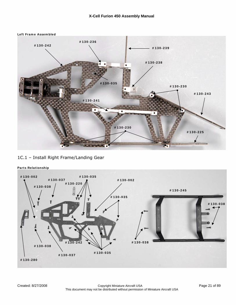
Left Frame Assembled
1C.1 – Install Right Frame/Landing Gear Parts Relationship
#130-245
#130-038
#130-038
#130-220
#130-280
#130-242
#130-002
#130-035
#130-002
#130-038
#130-038
#130-037
#130-035
#130-037
#130-035
#130-242
#130-243
#130-225
#130-239
#130-236
#130-035
#130-238
#130-230
#130-230
#130-241
X-Cell Furion 450 Assembly Manual
Page 22 of 89 Copyright Miniature Aircraft USA Created: 8/27/2008 This document may not be distributed without permission of Miniature Aircraft USA
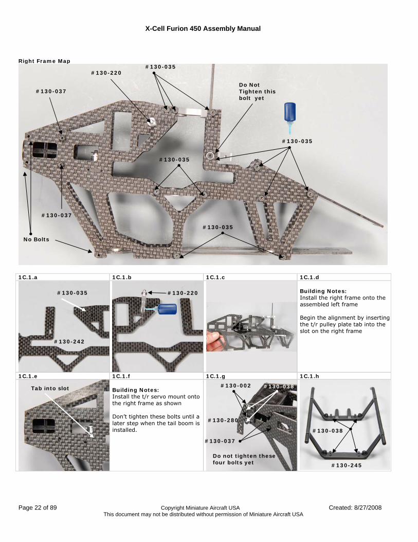
Right Frame Map
1C.1.a 1C.1.b 1C.1.c 1C.1.d
Building Notes: Install the right frame onto the assembled left frame Begin the alignment by inserting the t/r pulley plate tab into the slot on the right frame
1C.1.e 1C.1.f 1C.1.g 1C.1.h Building Notes: Install the t/r servo mount onto the right frame as shown Don’t tighten these bolts until a later step when the tail boom is installed.
#130-037
#130-035
#130-220
#130-037
#130-035
#130-035
#130-035
Do Not Tighten this bolt yet
#130-035 #130-220
#130-245
#130-038
#130-280
Do not tighten these four bolts yet
#130-037
#130-002 #130-038 Tab into slot
#130-242
No Bolts
X-Cell Furion 450 Assembly Manual
Created: 8/27/2008 Copyright Miniature Aircraft USA Page 23 of 89 This document may not be distributed without permission of Miniature Aircraft USA
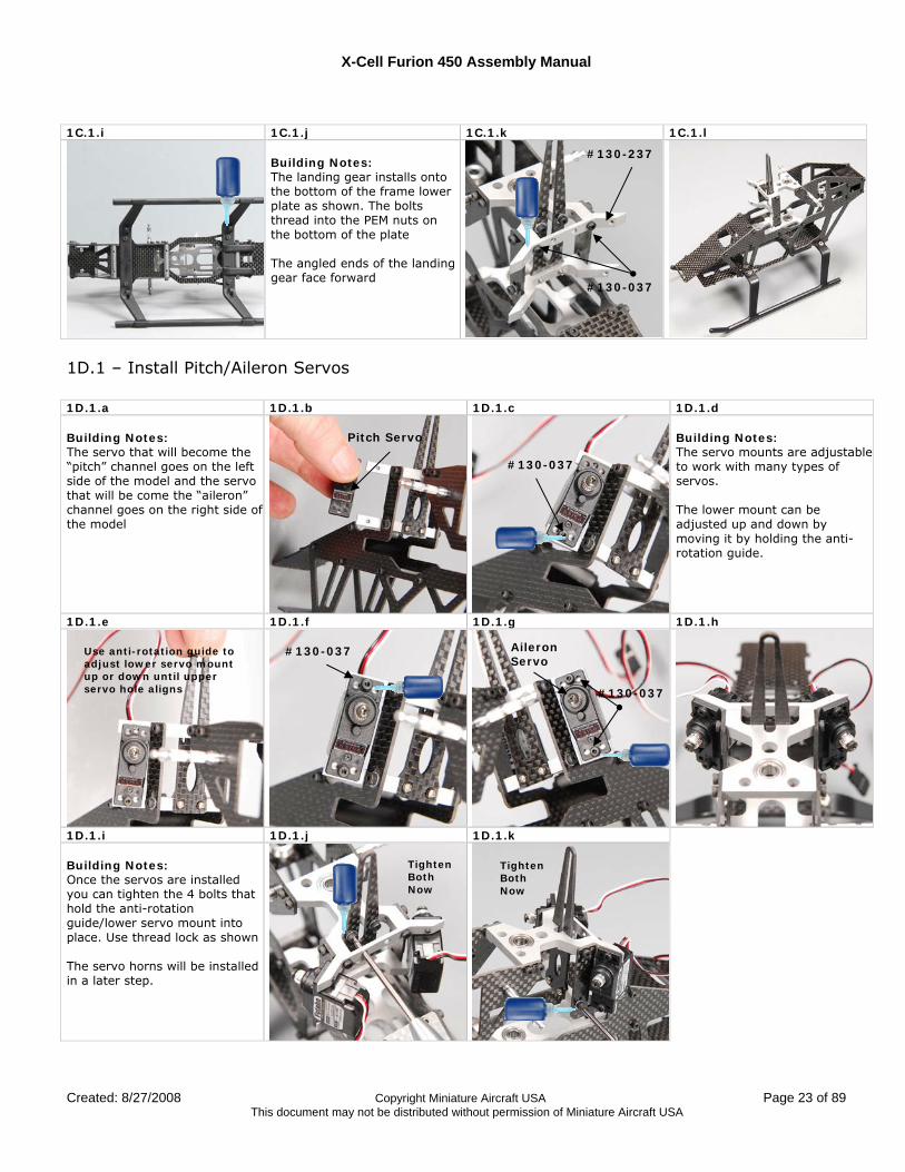
1C.1.i 1C.1.j 1C.1.k 1C.1.l
Building Notes: The landing gear installs onto the bottom of the frame lower plate as shown. The bolts thread into the PEM nuts on the bottom of the plate The angled ends of the landing gear face forward
1D.1 – Install Pitch/Aileron Servos 1D.1.a 1D.1.b 1D.1.c 1D.1.d Building Notes: The servo that will become the “pitch” channel goes on the left side of the model and the servo that will be come the “aileron” channel goes on the right side of the model
Building Notes: The servo mounts are adjustable to work with many types of servos. The lower mount can be adjusted up and down by moving it by holding the anti-rotation guide.
1D.1.e 1D.1.f 1D.1.g 1D.1.h
1D.1.i 1D.1.j 1D.1.k Building Notes: Once the servos are installed you can tighten the 4 bolts that hold the anti-rotation guide/lower servo mount into place. Use thread lock as shown The servo horns will be installed in a later step.
#130-037
Pitch Servo
Use anti-rotation guide to adjust lower servo mount up or down until upper servo hole aligns
#130-037 Aileron Servo
#130-037
Tighten Both Now
Tighten Both Now
#130-237
#130-037
X-Cell Furion 450 Assembly Manual
Page 24 of 89 Copyright Miniature Aircraft USA Created: 8/27/2008 This document may not be distributed without permission of Miniature Aircraft USA
Assembly Step #2 – Primary Drive
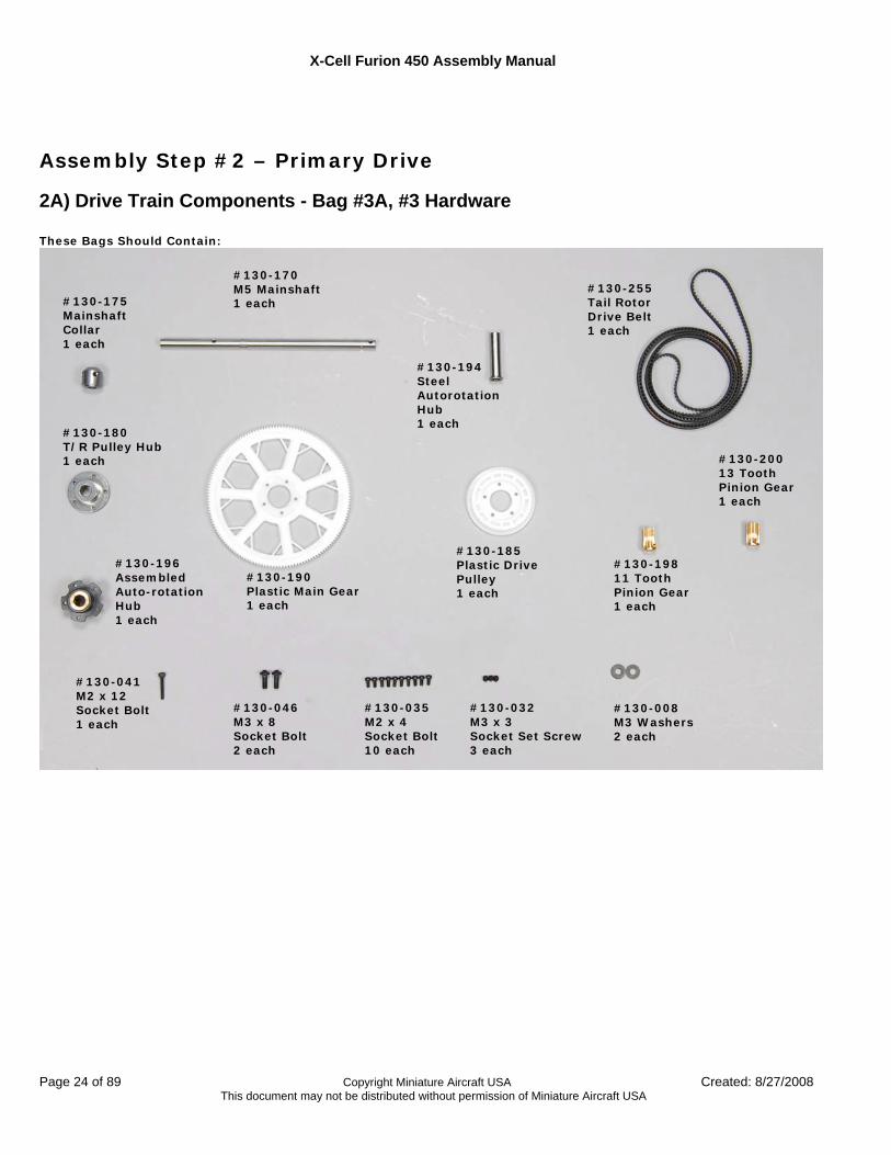
2A) Drive Train Components - Bag #3A, #3 Hardware These Bags Should Contain:
#130-170 M5 Mainshaft 1 each
#130-008 M3 Washers 2 each
#130-041 M2 x 12 Socket Bolt 1 each
#130-046 M3 x 8 Socket Bolt 2 each
#130-035 M2 x 4 Socket Bolt 10 each
#130-032 M3 x 3 Socket Set Screw 3 each
#130-175 Mainshaft Collar 1 each
#130-180 T/R Pulley Hub 1 each
#130-185 Plastic Drive Pulley 1 each
#130-190 Plastic Main Gear 1 each
#130-194 Steel Autorotation Hub 1 each
#130-196 Assembled Auto-rotation Hub 1 each
#130-198 11 Tooth Pinion Gear 1 each
#130-200 13 Tooth Pinion Gear 1 each
#130-255 Tail Rotor Drive Belt 1 each
X-Cell Furion 450 Assembly Manual
Created: 8/27/2008 Copyright Miniature Aircraft USA Page 25 of 89 This document may not be distributed without permission of Miniature Aircraft USA
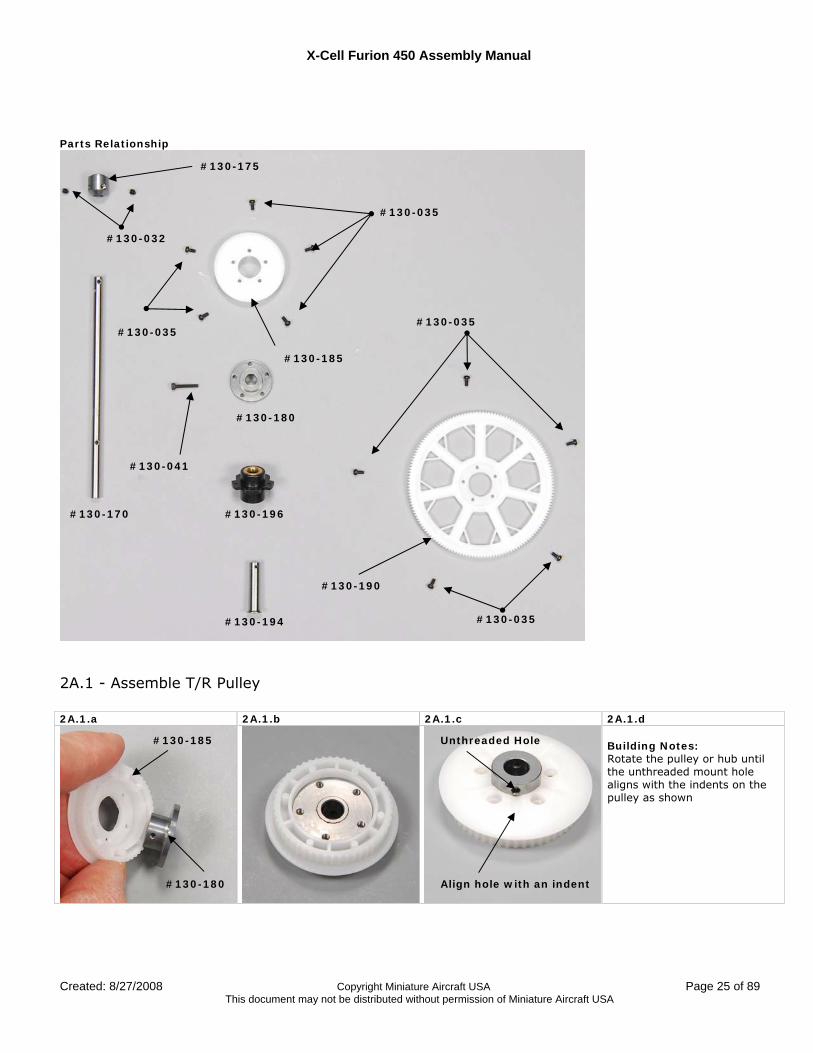
Parts Relationship
2A.1 - Assemble T/R Pulley 2A.1.a 2A.1.b 2A.1.c 2A.1.d
Building Notes: Rotate the pulley or hub until the unthreaded mount hole aligns with the indents on the pulley as shown
#130-035
#130-041
#130-035
#130-032
#130-194
#130-196
#130-180
#130-190
#130-185
#130-170
#130-175
#130-035
#130-035
#130-185
#130-180
Unthreaded Hole
Align hole with an indent
X-Cell Furion 450 Assembly Manual
Page 26 of 89 Copyright Miniature Aircraft USA Created: 8/27/2008 This document may not be distributed without permission of Miniature Aircraft USA
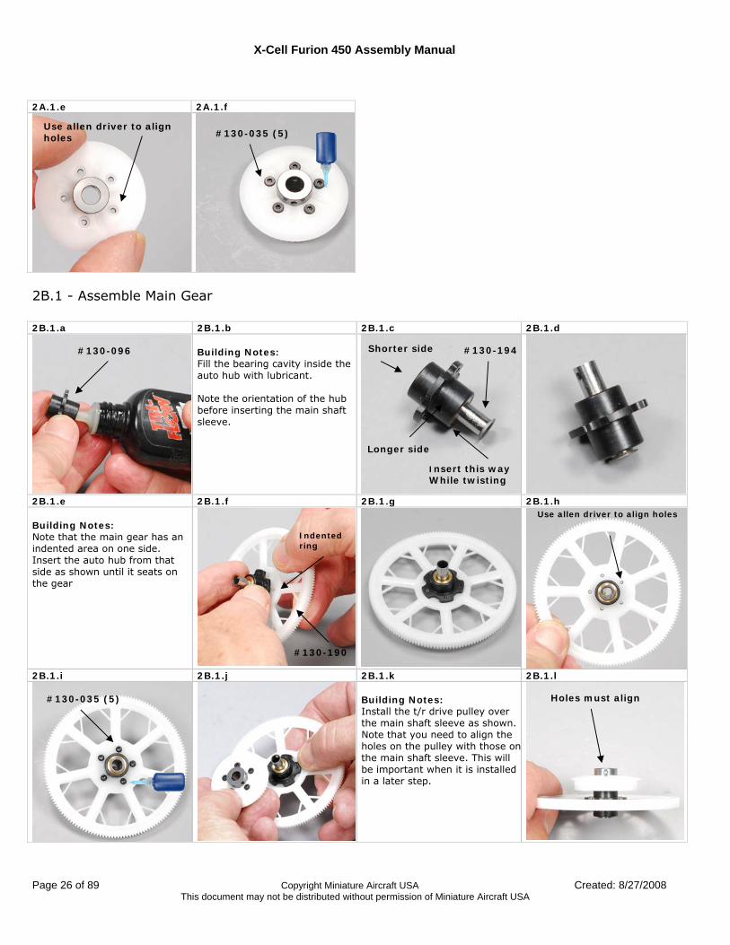
2A.1.e 2A.1.f
2B.1 - Assemble Main Gear 2B.1.a 2B.1.b 2B.1.c 2B.1.d
Building Notes: Fill the bearing cavity inside the auto hub with lubricant. Note the orientation of the hub before inserting the main shaft sleeve.
2B.1.e 2B.1.f 2B.1.g 2B.1.h Building Notes: Note that the main gear has an indented area on one side. Insert the auto hub from that side as shown until it seats on the gear
2B.1.i 2B.1.j 2B.1.k 2B.1.l
Building Notes: Install the t/r drive pulley over the main shaft sleeve as shown. Note that you need to align the holes on the pulley with those onthe main shaft sleeve. This will be important when it is installed in a later step.
#130-096
Longer side
Shorter side #130-194
Insert this way While twisting
Use allen driver to align holes
#130-190
Indented ring
#130-035 (5) Holes must align
#130-035 (5)
Use allen driver to align holes
X-Cell Furion 450 Assembly Manual
Created: 8/27/2008 Copyright Miniature Aircraft USA Page 27 of 89 This document may not be distributed without permission of Miniature Aircraft USA
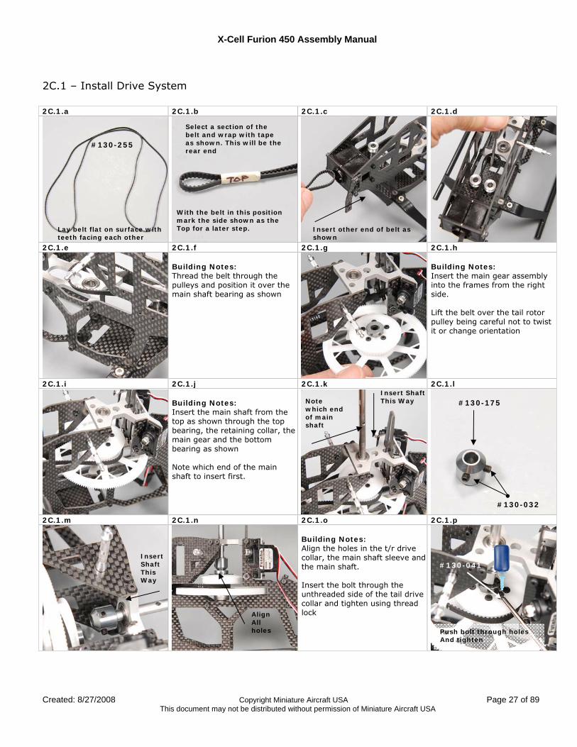
2C.1 – Install Drive System 2C.1.a 2C.1.b 2C.1.c 2C.1.d
2C.1.e 2C.1.f 2C.1.g 2C.1.h Building Notes: Thread the belt through the pulleys and position it over the main shaft bearing as shown
Building Notes: Insert the main gear assembly into the frames from the right side. Lift the belt over the tail rotor pulley being careful not to twist it or change orientation
2C.1.i 2C.1.j 2C.1.k 2C.1.l Building Notes: Insert the main shaft from the top as shown through the top bearing, the retaining collar, the main gear and the bottom bearing as shown Note which end of the main shaft to insert first.
2C.1.m 2C.1.n 2C.1.o 2C.1.p Building Notes: Align the holes in the t/r drive collar, the main shaft sleeve and the main shaft. Insert the bolt through the unthreaded side of the tail drive collar and tighten using thread lock
#130-255
Select a section of the belt and wrap with tape as shown. This will be the rear end
With the belt in this position mark the side shown as the Top for a later step. Insert other end of belt as
shown Lay belt flat on surface with teeth facing each other
Insert Shaft This Way Note
which end of main shaft
#130-175
#130-032
Push bolt through holes And tighten
Insert Shaft This Way
#130-041
Align All holes
X-Cell Furion 450 Assembly Manual
Page 28 of 89 Copyright Miniature Aircraft USA Created: 8/27/2008 This document may not be distributed without permission of Miniature Aircraft USA
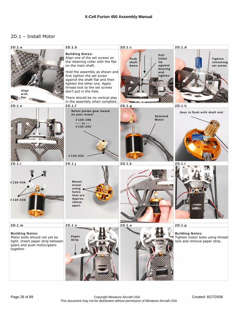
2D.1 – Install Motor 2D.1.a 2D.1.b 2D.1.c 2D.1.d
Building Notes: Align one of the set screws on the retaining collar with the flat on the main shaft.
Hold the assembly as shown and first tighten the set screw against the shaft flat and then tighten the other one. Apply thread lock to the set screws don’t put in the hole.
There should be no vertical play in the assembly when complete.
2D.1.e 2D.1.f 2D.1.g 2D.1.h
2D.1.i 2D.1.j 2D.1.k 2D.1.l
2D.1.m 2D.1.n 2D.1.o 2D.1.p Building Notes: Motor bolts should not yet be tight. Insert paper strip between gears and push motor/gears together
Building Notes: Tighten motor bolts using thread lock and remove paper strip.
#130-046
#130-008
Mount motor using holes that are Approx. 18mm apart
Gear is flush with shaft end Selected
Motor
#130-032
#130-198 ---- or --- #130-200
Tighten remaining set screw
Push shaft down
Pull Collar Up against bearing and tighten
Align with flat
Paper Strip
Select pinion gear based on your motor
X-Cell Furion 450 Assembly Manual
Created: 8/27/2008 Copyright Miniature Aircraft USA Page 29 of 89 This document may not be distributed without permission of Miniature Aircraft USA
2D.1.q 2D.1.r
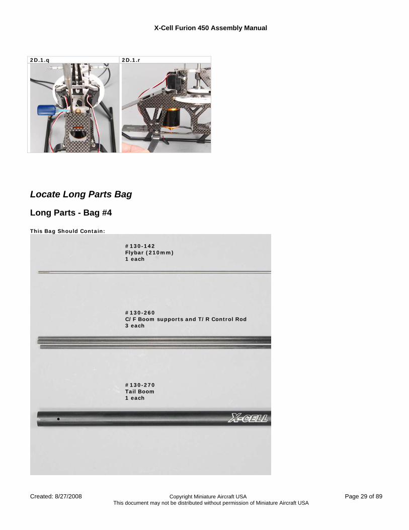
Locate Long Parts Bag
Long Parts - Bag #4 This Bag Should Contain:
#130-142 Flybar (210mm) 1 each
#130-260 C/F Boom supports and T/R Control Rod 3 each
#130-270 Tail Boom 1 each
X-Cell Furion 450 Assembly Manual
Page 30 of 89 Copyright Miniature Aircraft USA Created: 8/27/2008 This document may not be distributed without permission of Miniature Aircraft USA
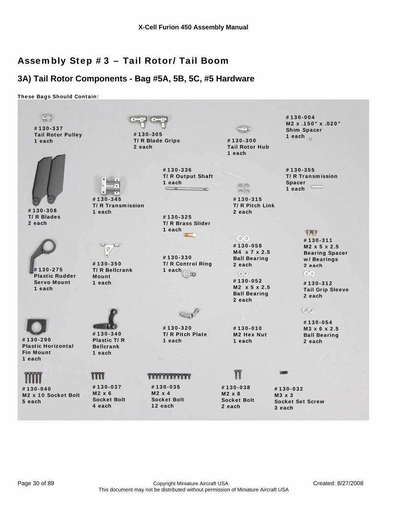
Assembly Step #3 – Tail Rotor/Tail Boom
3A) Tail Rotor Components - Bag #5A, 5B, 5C, #5 Hardware These Bags Should Contain:
#130-305 T/R Blade Grips 2 each
#130-058 M4 x 7 x 2.5 Ball Bearing 2 each
#130-290 Plastic Horizontal Fin Mount 1 each
#130-340 Plastic T/R Bellcrank 1 each
#130-320 T/R Pitch Plate 1 each
#130-330 T/R Control Ring 1 each
#130-337 Tail Rotor Pulley 1 each
#130-308 T/R Blades 2 each
#130-325 T/R Brass Slider 1 each
#130-350 T/R Bellcrank Mount 1 each
#130-300 Tail Rotor Hub 1 each
#130-275 Plastic Rudder Servo Mount 1 each
#130-054 M3 x 6 x 2.5 Ball Bearing 2 each
#130-345 T/R Transmission 1 each
#130-004 M2 x .150” x .020” Shim Spacer 1 each
#130-336 T/R Output Shaft 1 each
#130-315 T/R Pitch Link 2 each
#130-355 T/R Transmission Spacer 1 each
#130-311 M2 x 5 x 2.5 Bearing Spacer w/Bearings 2 each
#130-052 M2 x 5 x 2.5 Ball Bearing 2 each
#130-312 Tail Grip Sleeve 2 each
#130-040 M2 x 10 Socket Bolt 5 each
#130-037 M2 x 6 Socket Bolt 4 each
#130-035 M2 x 4 Socket Bolt 12 each
#130-038 M2 x 8 Socket Bolt 2 each
#130-032 M3 x 3 Socket Set Screw 3 each
#130-010 M2 Hex Nut 1 each
X-Cell Furion 450 Assembly Manual
Created: 8/27/2008 Copyright Miniature Aircraft USA Page 31 of 89 This document may not be distributed without permission of Miniature Aircraft USA
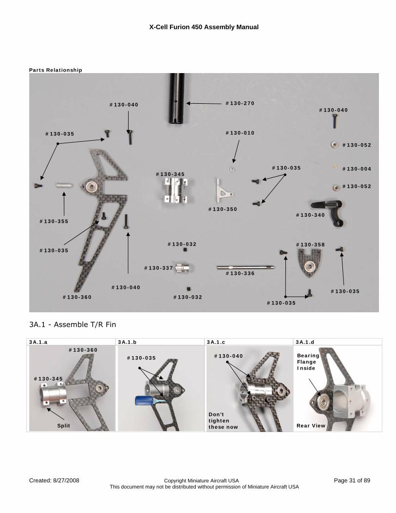
Parts Relationship
3A.1 - Assemble T/R Fin 3A.1.a 3A.1.b 3A.1.c 3A.1.d
#130-270
#130-035
#130-035
#130-336 #130-337
#130-355
#130-360
#130-358
#130-035
#130-040 #130-040
#130-010
#130-345
#130-350
#130-040
#130-004
#130-052
#130-052
#130-340
#130-032
#130-032 #130-035
#130-360
#130-345
#130-035
#130-035 #130-040
Don’t tighten these now Split
Bearing Flange Inside
Rear View
X-Cell Furion 450 Assembly Manual
Page 32 of 89 Copyright Miniature Aircraft USA Created: 8/27/2008 This document may not be distributed without permission of Miniature Aircraft USA
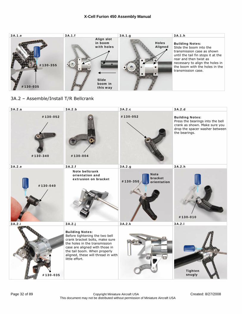
3A.1.e 3A.1.f 3A.1.g 3A.1.h
Building Notes: Slide the boom into the transmission case as shown until the tail fin stops it at the rear and then twist as necessary to align the holes in the boom with the holes in the transmission case.
3A.2 – Assemble/Install T/R Bellcrank 3A.2.a 3A.2.b 3A.2.c 3A.2.d
Building Notes: Press the bearings into the bell crank as shown. Make sure you drop the spacer washer between the bearings.
3A.2.e 3A.2.f 3A.2.g 3A.2.h
3A.2.i 3A.2.j 3A.2.k 3A.2.l
Building Notes: Before tightening the two bell crank bracket bolts, make sure the holes in the transmission case are aligned with those in the tail boom. When properly aligned, these will thread in with little effort.
#130-340
#130-052
#130-004
#130-052
#130-040
Tighten snugly #130-035
#130-010
#130-350
Note bracket orientation
Note bellcrank orientation and extrusion on bracket
Align slot in boom with holes
Slide boom in this way #130-035
#130-355
Holes Aligned
X-Cell Furion 450 Assembly Manual
Created: 8/27/2008 Copyright Miniature Aircraft USA Page 33 of 89 This document may not be distributed without permission of Miniature Aircraft USA
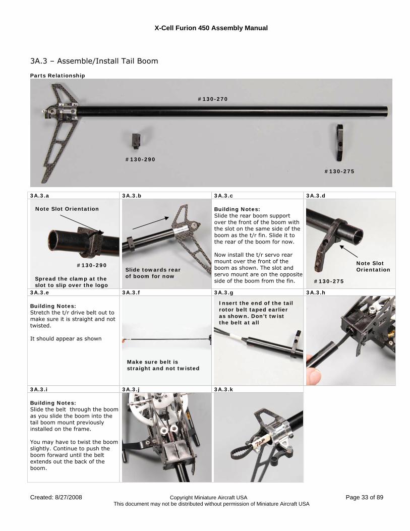
3A.3 – Assemble/Install Tail Boom
Parts Relationship
3A.3.a 3A.3.b 3A.3.c 3A.3.d Building Notes: Slide the rear boom support over the front of the boom with the slot on the same side of the boom as the t/r fin. Slide it to the rear of the boom for now. Now install the t/r servo rear mount over the front of the boom as shown. The slot and servo mount are on the opposite side of the boom from the fin.
3A.3.e 3A.3.f 3A.3.g 3A.3.h Building Notes: Stretch the t/r drive belt out to make sure it is straight and not twisted. It should appear as shown
3A.3.i 3A.3.j 3A.3.k Building Notes: Slide the belt through the boom as you slide the boom into the tail boom mount previously installed on the frame. You may have to twist the boom slightly. Continue to push the boom forward until the belt extends out the back of the boom.
#130-270
#130-275
#130-290
#130-290
Note Slot Orientation
Slide towards rear of boom for now Spread the clamp at the
slot to slip over the logo
Insert the end of the tail rotor belt taped earlier as shown. Don’t twist the belt at all
Make sure belt is straight and not twisted
#130-275
Note Slot Orientation
X-Cell Furion 450 Assembly Manual
Page 34 of 89 Copyright Miniature Aircraft USA Created: 8/27/2008 This document may not be distributed without permission of Miniature Aircraft USA
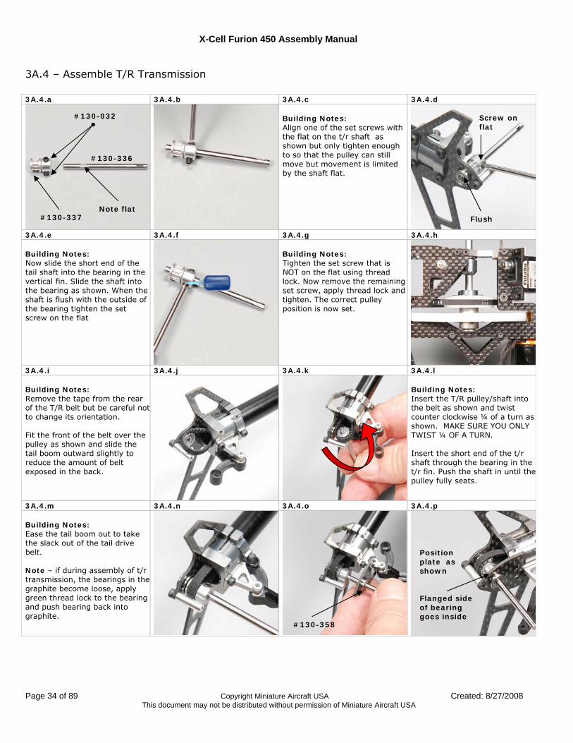
3A.4 – Assemble T/R Transmission 3A.4.a 3A.4.b 3A.4.c 3A.4.d
Building Notes: Align one of the set screws with the flat on the t/r shaft as shown but only tighten enough to so that the pulley can still move but movement is limited by the shaft flat.
3A.4.e 3A.4.f 3A.4.g 3A.4.h Building Notes: Now slide the short end of the tail shaft into the bearing in the vertical fin. Slide the shaft into the bearing as shown. When the shaft is flush with the outside of the bearing tighten the set screw on the flat
Building Notes: Tighten the set screw that is NOT on the flat using thread lock. Now remove the remaining set screw, apply thread lock and tighten. The correct pulley position is now set.
3A.4.i 3A.4.j 3A.4.k 3A.4.l Building Notes: Remove the tape from the rear of the T/R belt but be careful not to change its orientation. Fit the front of the belt over the pulley as shown and slide the tail boom outward slightly to reduce the amount of belt exposed in the back.
Building Notes: Insert the T/R pulley/shaft into the belt as shown and twist counter clockwise ¼ of a turn as shown. MAKE SURE YOU ONLY TWIST ¼ OF A TURN. Insert the short end of the t/r shaft through the bearing in the t/r fin. Push the shaft in until the pulley fully seats.
3A.4.m 3A.4.n 3A.4.o 3A.4.p Building Notes: Ease the tail boom out to take the slack out of the tail drive belt. Note – if during assembly of t/r transmission, the bearings in the graphite become loose, apply green thread lock to the bearing and push bearing back into graphite.
#130-336
#130-337
#130-032
Note flat Flush
Screw on flat
#130-358
Position plate as shown Flanged side of bearing goes inside
X-Cell Furion 450 Assembly Manual
Created: 8/27/2008 Copyright Miniature Aircraft USA Page 35 of 89 This document may not be distributed without permission of Miniature Aircraft USA
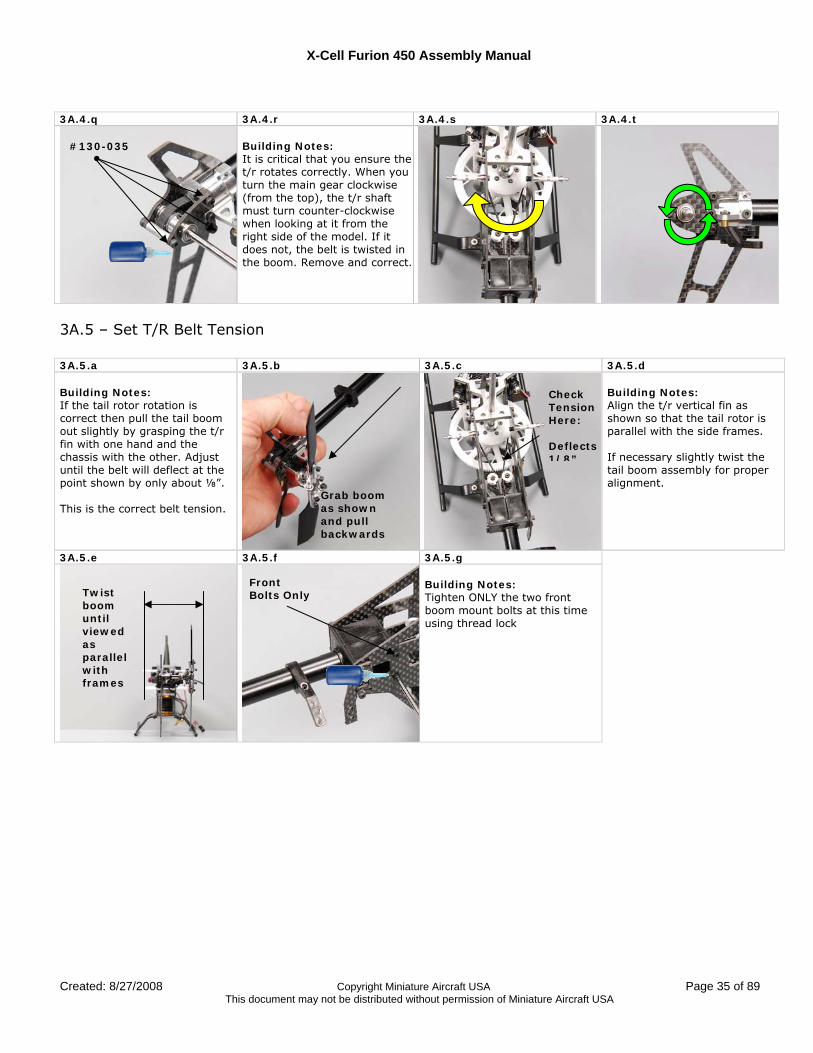
3A.4.q 3A.4.r 3A.4.s 3A.4.t
Building Notes: It is critical that you ensure the t/r rotates correctly. When you turn the main gear clockwise (from the top), the t/r shaft must turn counter-clockwise when looking at it from the right side of the model. If it does not, the belt is twisted in the boom. Remove and correct.
3A.5 – Set T/R Belt Tension 3A.5.a 3A.5.b 3A.5.c 3A.5.d Building Notes: If the tail rotor rotation is correct then pull the tail boom out slightly by grasping the t/r fin with one hand and the chassis with the other. Adjust until the belt will deflect at the point shown by only about ⅛”. This is the correct belt tension.
Building Notes: Align the t/r vertical fin as shown so that the tail rotor is parallel with the side frames. If necessary slightly twist the tail boom assembly for proper alignment.
3A.5.e 3A.5.f 3A.5.g Building Notes: Tighten ONLY the two front boom mount bolts at this time using thread lock
Check Tension Here: Deflects 1/8”
Grab boom as shown and pull backwards
Twist boom until viewed as parallel with frames
#130-035
Front Bolts Only
X-Cell Furion 450 Assembly Manual
Page 36 of 89 Copyright Miniature Aircraft USA Created: 8/27/2008 This document may not be distributed without permission of Miniature Aircraft USA
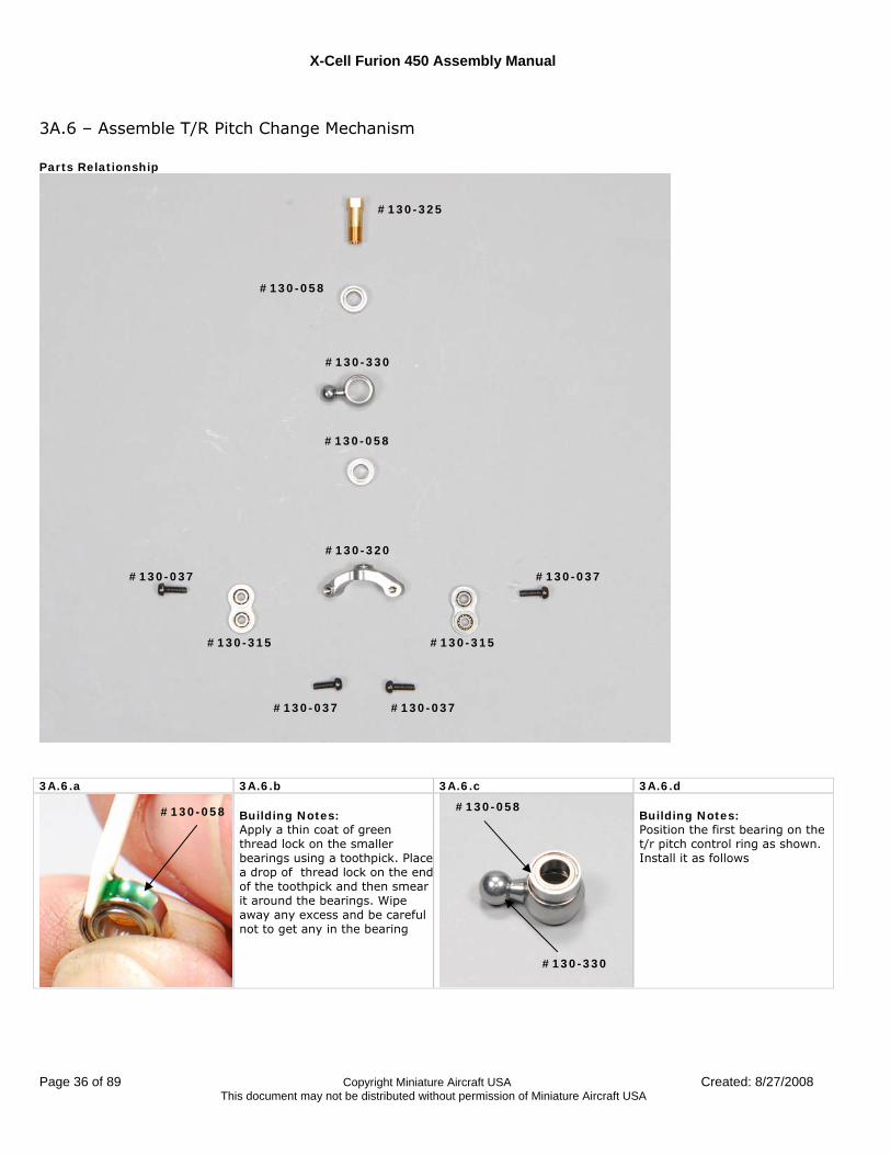
3A.6 – Assemble T/R Pitch Change Mechanism Parts Relationship
3A.6.a 3A.6.b 3A.6.c 3A.6.d
Building Notes: Apply a thin coat of green thread lock on the smaller bearings using a toothpick. Place a drop of thread lock on the endof the toothpick and then smear it around the bearings. Wipe away any excess and be careful not to get any in the bearing
Building Notes: Position the first bearing on the t/r pitch control ring as shown. Install it as follows
#130-325
#130-058
#130-058
#130-330
#130-037 #130-037
#130-315 #130-315
#130-320
#130-037 #130-037
#130-058 #130-058
#130-330
X-Cell Furion 450 Assembly Manual
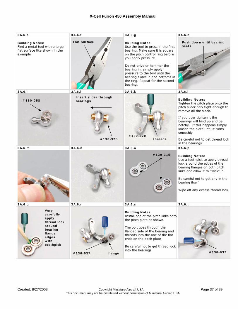
Created: 8/27/2008 Copyright Miniature Aircraft USA Page 37 of 89 This document may not be distributed without permission of Miniature Aircraft USA
3A.6.e 3A.6.f 3A.6.g 3A.6.h Building Notes: Find a metal tool with a large flat surface like shown in the example
Building Notes: Use the tool to press in the first bearing. Make sure it is square on the pitch control ring before you apply pressure. Do not drive or hammer the bearing in, simply apply pressure to the tool until the bearing slides in and bottoms in the ring. Repeat for the second bearing.
3A.6.i 3A.6.j 3A.6.k 3A.6.l
Building Notes: Tighten the pitch plate onto the pitch slider only tight enough to remove all the slack.
If you over tighten it the bearings will bind up and be notchy. If this happens simply loosen the plate until it turns smoothly
Be careful not to get thread lock in the bearings
3A.6.m 3A.6.n 3A.6.o 3A.6.p
Building Notes: Use a toothpick to apply thread lock around the edges of the bearing flanges on both pitch links and allow it to “wick” in. Be careful not to get any in the bearing itself Wipe off any excess thread lock.
3A.6.q 3A.6.r 3A.6.s 3A.6.t
Building Notes: Install one of the pitch links ontothe pitch plate as shown. The bolt goes through the flanged side of the bearing and threads into the one of the flat ends on the pitch plate Be careful not to get thread lock into the bearings
Flat Surface Push down until bearing seats
#130-058
#130-325
Insert slider through bearings
#130-320 threads
#130-315
#130-037
Very carefully apply thread lock around bearing flange edges with toothpick
#130-037
flange
X-Cell Furion 450 Assembly Manual
Page 38 of 89 Copyright Miniature Aircraft USA Created: 8/27/2008 This document may not be distributed without permission of Miniature Aircraft USA
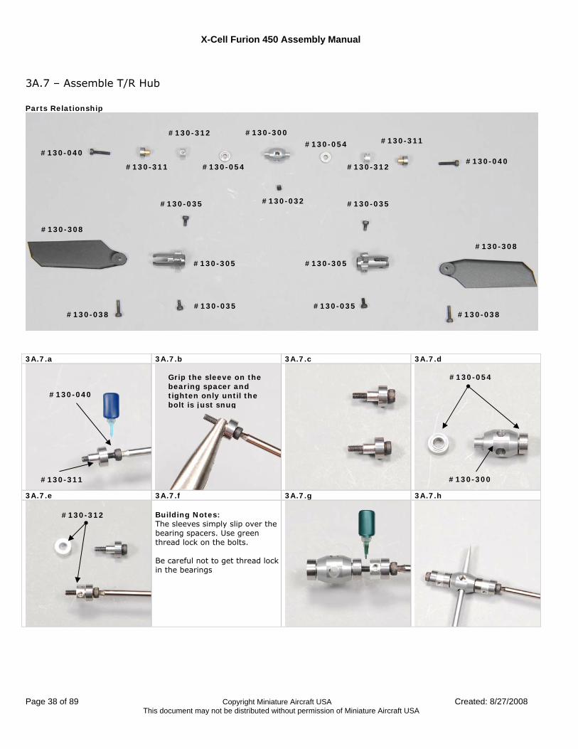
3A.7 – Assemble T/R Hub Parts Relationship
3A.7.a 3A.7.b 3A.7.c 3A.7.d
3A.7.e 3A.7.f 3A.7.g 3A.7.h Building Notes: The sleeves simply slip over the bearing spacers. Use green thread lock on the bolts. Be careful not to get thread lock in the bearings
#130-040 #130-040
#130-311
#130-311 #130-312
#130-312 #130-054
#130-054
#130-300
#130-032 #130-035 #130-035
#130-035 #130-035
#130-305 #130-305
#130-308
#130-308
#130-038 #130-038
#130-300 #130-311
Grip the sleeve on the bearing spacer and tighten only until the bolt is just snug
#130-040
#130-054
#130-312

X-Cell Furion 450 Assembly Manual
Created: 8/27/2008 Copyright Miniature Aircraft USA Page 39 of 89 This document may not be distributed without permission of Miniature Aircraft USA
3A.7.i 3A.7.j 3A.7.k 3A.7.l
Building Notes: Install the blade grip over the bearing stack as shown. The mount holes on the blade grip must align with the holes in the bearing sleeve as shown. Use a small allen tool to align if necessary. Push the t/r grip towards the center of the hub until it bottoms out. Then install the mount bolts.
3A.7.m 3A.7.n 3A.7.o 3A.7.p Building Notes: If the grips and spacer are properly aligned, the mount bolts will install with little effort. If they do not thread in easily re-check the alignment and repeat.
3A.7.q 3A.7.r 3A.7.s 3A.7.t Building Notes: Install the t/r blades as shown. The leading edge of the blades should install as shown. Look closely at the blade arms, one side of the hole is threaded and the other is not. The bolts pass through the side that is not threaded, through the blade and then thread into the other side
3A.7.u 3A.7.v
Building Notes: Partially thread the set screw into the threaded hole on the t/r hub. It should not protrude into the inside of the t/r hub. Do not use thread lock at this time.
Aligned #130-305
Slides over bearings Align holes
Slides over bearings
#130-032
Note relationship of leading edge to blade control arm
Note relationship of leading edge to blade control arm
Insert This way
#130-308
#130-038
Unthreaded hole
#130-035
#130-035
X-Cell Furion 450 Assembly Manual
Page 40 of 89 Copyright Miniature Aircraft USA Created: 8/27/2008 This document may not be distributed without permission of Miniature Aircraft USA
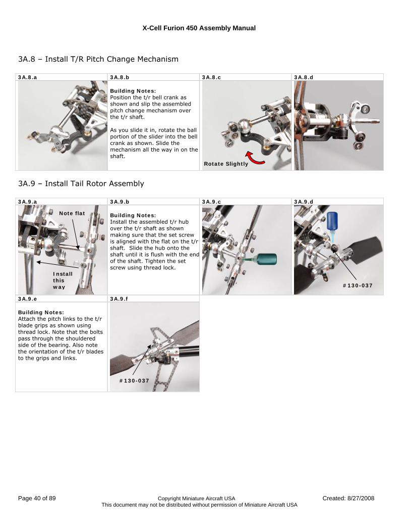
3A.8 – Install T/R Pitch Change Mechanism 3A.8.a 3A.8.b 3A.8.c 3A.8.d
Building Notes: Position the t/r bell crank as shown and slip the assembled pitch change mechanism over the t/r shaft. As you slide it in, rotate the ball portion of the slider into the bell crank as shown. Slide the mechanism all the way in on the shaft.
3A.9 – Install Tail Rotor Assembly 3A.9.a 3A.9.b 3A.9.c 3A.9.d
Building Notes: Install the assembled t/r hub over the t/r shaft as shown making sure that the set screw is aligned with the flat on the t/r shaft. Slide the hub onto the shaft until it is flush with the endof the shaft. Tighten the set screw using thread lock.
3A.9.e 3A.9.f Building Notes: Attach the pitch links to the t/r blade grips as shown using thread lock. Note that the bolts pass through the shouldered side of the bearing. Also note the orientation of the t/r blades to the grips and links.
#130-037
Install this way
Note flat
Rotate Slightly
#130-037
X-Cell Furion 450 Assembly Manual
Created: 8/27/2008 Copyright Miniature Aircraft USA Page 41 of 89 This document may not be distributed without permission of Miniature Aircraft USA
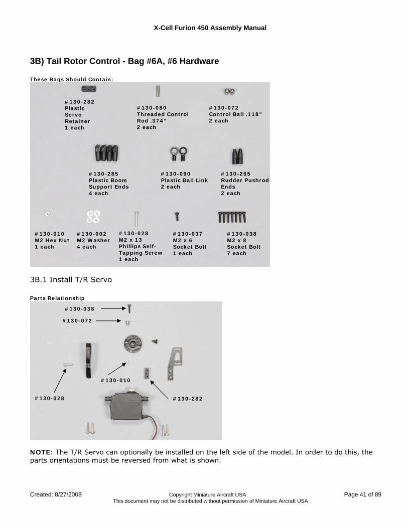
3B) Tail Rotor Control - Bag #6A, #6 Hardware These Bags Should Contain:
3B.1 Install T/R Servo Parts Relationship
NOTE: The T/R Servo can optionally be installed on the left side of the model. In order to do this, the parts orientations must be reversed from what is shown.
#130-282 Plastic Servo Retainer 1 each
#130-080 Threaded Control Rod .374” 2 each
#130-072 Control Ball .118” 2 each
#130-285 Plastic Boom Support Ends 4 each
#130-090 Plastic Ball Link 2 each
#130-265 Rudder Pushrod Ends 2 each
#130-038 M2 x 8 Socket Bolt 7 each
#130-037 M2 x 6 Socket Bolt 1 each
#130-028 M2 x 13 Phillips Self- Tapping Screw 1 each
#130-002 M2 Washer 4 each
#130-010 M2 Hex Nut 1 each
#130-282
#130-038
#130-072
#130-028
#130-010
X-Cell Furion 450 Assembly Manual
Page 42 of 89 Copyright Miniature Aircraft USA Created: 8/27/2008 This document may not be distributed without permission of Miniature Aircraft USA
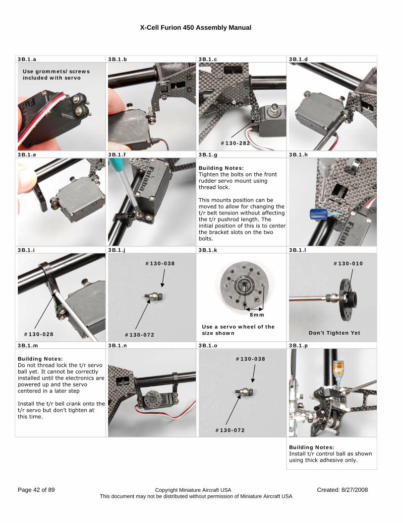
3B.1.a 3B.1.b 3B.1.c 3B.1.d
3B.1.e 3B.1.f 3B.1.g 3B.1.h Building Notes: Tighten the bolts on the front rudder servo mount using thread lock. This mounts position can be moved to allow for changing the t/r belt tension without affecting the t/r pushrod length. The initial position of this is to center the bracket slots on the two bolts.
3B.1.i 3B.1.j 3B.1.k 3B.1.l
3B.1.m 3B.1.n 3B.1.o 3B.1.p Building Notes: Do not thread lock the t/r servo ball yet. It cannot be correctly installed until the electronics are powered up and the servo centered in a later step Install the t/r bell crank onto the t/r servo but don’t tighten at this time.
Building Notes: Install t/r control ball as shown using thick adhesive only.
#130-282
#130-028 #130-072
#130-038 #130-010
Use a servo wheel of the size shown
8mm
Don’t Tighten Yet
#130-072
#130-038
Use grommets/screws included with servo
X-Cell Furion 450 Assembly Manual
Created: 8/27/2008 Copyright Miniature Aircraft USA Page 43 of 89 This document may not be distributed without permission of Miniature Aircraft USA
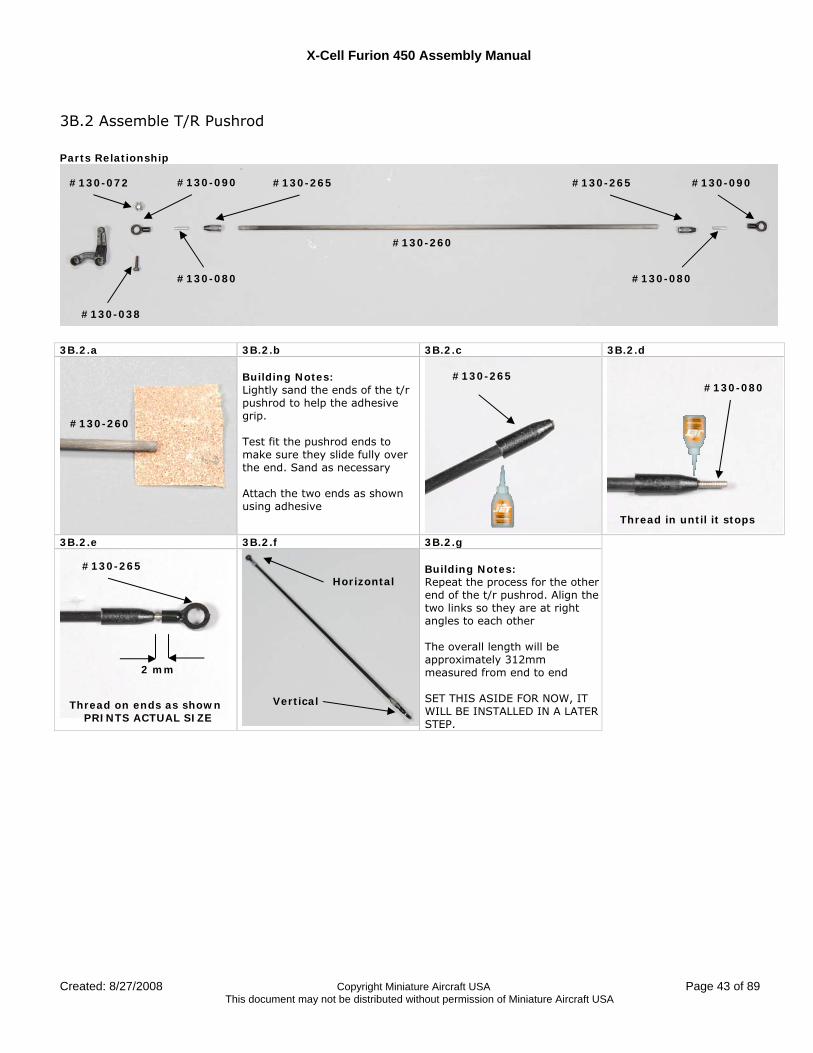
3B.2 Assemble T/R Pushrod Parts Relationship
3B.2.a 3B.2.b 3B.2.c 3B.2.d
Building Notes: Lightly sand the ends of the t/r pushrod to help the adhesive grip. Test fit the pushrod ends to make sure they slide fully over the end. Sand as necessary Attach the two ends as shown using adhesive
3B.2.e 3B.2.f 3B.2.g
Building Notes: Repeat the process for the other end of the t/r pushrod. Align the two links so they are at right angles to each other The overall length will be approximately 312mm measured from end to end SET THIS ASIDE FOR NOW, IT WILL BE INSTALLED IN A LATER STEP.
#130-072
#130-038
#130-090
#130-080
#130-265
#130-260
#130-265
#130-080
#130-090
#130-265
#130-080
Thread in until it stops
#130-260
#130-265
Thread on ends as shown PRINTS ACTUAL SIZE
Horizontal
Vertical
2 mm
X-Cell Furion 450 Assembly Manual
Page 44 of 89 Copyright Miniature Aircraft USA Created: 8/27/2008 This document may not be distributed without permission of Miniature Aircraft USA
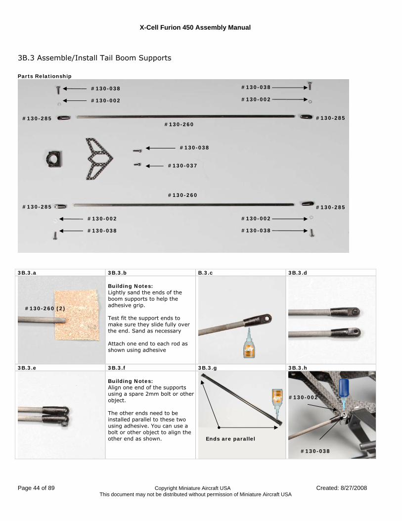
3B.3 Assemble/Install Tail Boom Supports Parts Relationship
3B.3.a 3B.3.b B.3.c 3B.3.d
Building Notes: Lightly sand the ends of the boom supports to help the adhesive grip. Test fit the support ends to make sure they slide fully over the end. Sand as necessary Attach one end to each rod as shown using adhesive
3B.3.e 3B.3.f 3B.3.g 3B.3.h Building Notes: Align one end of the supports using a spare 2mm bolt or other object. The other ends need to be installed parallel to these two using adhesive. You can use a bolt or other object to align the other end as shown.
#130-038
#130-037
#130-038
#130-002
#130-285
#130-285
#130-002
#130-038
#130-038
#130-002
#130-285
#130-285
#130-002
#130-038
#130-260
#130-260
#130-260 (2)
Ends are parallel
#130-038
#130-002
X-Cell Furion 450 Assembly Manual
Created: 8/27/2008 Copyright Miniature Aircraft USA Page 45 of 89 This document may not be distributed without permission of Miniature Aircraft USA
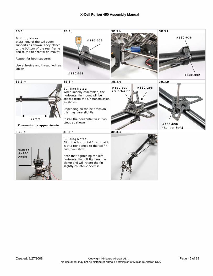
3B.3.i 3B.3.j 3B.3.k 3B.3.l Building Notes: Install one of the tail boom supports as shown. They attach to the bottom of the rear frame and to the horizontal fin mount Repeat for both supports Use adhesive and thread lock as shown
3B.3.m 3B.3.n 3B.3.o 3B.3.p Building Notes: When initially assembled, the horizontal fin mount will be spaced from the t/r transmission as shown. Depending on the belt tension this may vary slightly Install the horizontal fin in two steps as shown
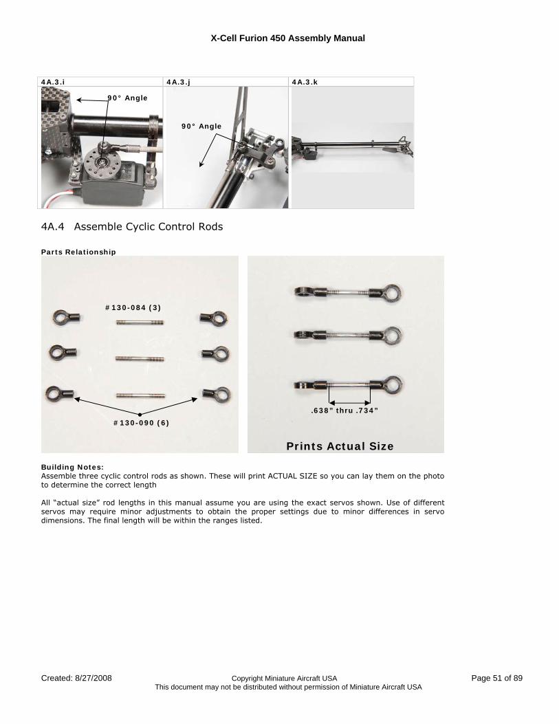
3B.3.q 3B.3.r 3B.3.s Building Notes: Align the horizontal fin so that it is at a right angle to the tail fin and main shaft. Note that tightening the left horizontal fin bolt tightens the clamp and will rotate the fin slightly counter-clockwise.
#130-038
#130-002
77mm
#130-037 (Shorter Bolt)
#130-038 (Longer Bolt)
Viewed As 90° Angle
#130-295
#130-002
#130-038
Dimension is approximate

X-Cell Furion 450 Assembly Manual
Page 46 of 89 Copyright Miniature Aircraft USA Created: 8/27/2008 This document may not be distributed without permission of Miniature Aircraft USA
Assembly Step #4 – Control Systems
4A) Electronics Installation/Main Control Components - Bag #7A, #7B, #7 Hardware These Bags Should Contain:
#130-282 Plastic Servo Retainer 2 each
#130-076 Control Ball .198” 3 each
#130-074 Control Ball .157” 2 each
#130-070 Control Ball .118” 7 each
#130-165 Anti-rotation Pin 1 each
#130-155 Plastic Washout Link 2 each
#130-150 Aluminum Washout Arms 2 each
#130-145 Washout Hub 1 each
#130-168 Assembled Swashplate 1 each
#130-090 Plastic Ball Link 6 each
#130-084 Control Rod 1.013” 3 each
#130-052 M2 x 5 x 2.5 Ball Bearings 4 each
#130-010 M2 Hex Nut 3 each
#130-040 M2 x 10 Socket Bolt 1 each
#130-038 M2 x 8 Socket Bolt 2 each
#130-153 Machined Washout Link Screw 2 each
#130-020 M2 x 8 Phillips Tapered Head Screw 2 each
#130-019 M2 x 6 Phillips Tapered Head Screw 5 each
#130-022 M2 x 8.50 Phillips Tapered Head Screw 2 each
#130-004 M2 x .150” x .020” Shim Washer 2 each
#130-030 M2 x 8 Shouldered Bolt 2 each
#130-041 M2 x 12 Socket Bolt 1 each
#130-035 M2 x 4 Socket Bolt 3 each
X-Cell Furion 450 Assembly Manual
Created: 8/27/2008 Copyright Miniature Aircraft USA Page 47 of 89 This document may not be distributed without permission of Miniature Aircraft USA
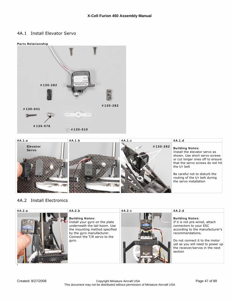
4A.1 Install Elevator Servo Parts Relationship
4A.1.a 4A.1.b 4A.1.c 4A.1.d
Building Notes: Install the elevator servo as shown. Use short servo screws or cut longer ones off to ensure that the servo screws do not hitthe t/r belt Be careful not to disturb the routing of the t/r belt during the servo installation
4A.2 Install Electronics 4A.2.a 4A.2.b 4A.2.c 4A.2.d
Building Notes: Install your gyro on the plate underneath the tail boom. Use the mounting method specified by the gyro manufacturer. Connect the T/R servo to the gyro.
Building Notes: If it is not pre-wired, attach connectors to your ESC according to the manufacturer’s recommendations. Do not connect it to the motor yet as you will need to power up the receiver/servos in the next section
‘
#130-282
#130-282 #130-041
#130-010 #130-076
Elevator Servo
#130-282
X-Cell Furion 450 Assembly Manual
Page 48 of 89 Copyright Miniature Aircraft USA Created: 8/27/2008 This document may not be distributed without permission of Miniature Aircraft USA
4A.2.e 4A.2.f 4A.2.g 4A.2.h
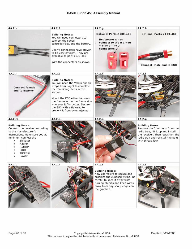
Building Notes: You will need connectors to connect the speed controller/BEC and the battery. Dean’s connectors have proven to be very efficient. They are available as part #130-460 Wire the connectors as shown
4A.2.i 4A.2.j 4A.2.k 4A.2.l Building Notes: You will need the Velcro and tie wraps from Bag 9 to complete the remaining steps in this section. Mount the ESC either between the frames or on the frame side wherever it fits better. Secure the ESC with a tie wrap to prevent it from being ejected.
4A.2.m 4A.2.n 4A.2.o 4A.2.p Building Notes: Connect the receiver according to the manufacturer’s instructions. Make sure you at minimum connect the
• Elevator • Aileron • Rudder • Pitch • Throttle • Power
Building Notes: Remove the front bolts from the radio tray, lift it up and install the receiver. Then reposition the radio tray and reinstall the bolts with thread lock
4A.2.q 4A.2.r 4A.2.s 4A.2.t Building Notes: Now use Velcro to secure and organize the exposed wiring. Be careful to keep it away from turning objects and keep wires away from any sharp edges on the graphite.
Red power wires connect to the marked + side of the connectors
Optional Parts #130-460 Optional Parts #130-460
Connect male end to ESC
Connect female end to Battery

X-Cell Furion 450 Assembly Manual
Created: 8/27/2008 Copyright Miniature Aircraft USA Page 49 of 89 This document may not be distributed without permission of Miniature Aircraft USA
4A.2.u 4A.2.v 4A.2.w 4A.2.x
Building Notes: Secure gyro using Velcro as shown. You will need to slightly trim the Velcro width so that it fits into the slots on each side of the front boom support as shown.
4A.2.y 4A.2.z 4A.2.aa 4A.2.bb Building Notes: Refer to the Initial Setup for Servo Centering procedure found in the Model Setup section of this manual For each servo select a servo arm and find the position that the arms are nearly perpendicular to the servo. Trim and mount the arms as shown in the following steps
Building Notes: In the following steps you will assemble the servo arms. Select arms that will allow the control balls to be placed at distance from the servo center shown.
4A.2.cc 4A.2.dd 4A.2.ee
4A.2.ff
Building Notes: Although the plastic links can be installed on either side, one side is molded differently and will install easier with less effort. Note the differences on the photo. The side of the link with the beveled edge should be installed first over a ball or should face inside on a ball. The side of the link with no bevel should face outside on a ball.
13mm
Ball Link Orientation
No Bevel
No Ring
Beveled Edge
Mold Ring
Faces Inside Faces Outside
Antenna Routing
X-Cell Furion 450 Assembly Manual
Page 50 of 89 Copyright Miniature Aircraft USA Created: 8/27/2008 This document may not be distributed without permission of Miniature Aircraft USA
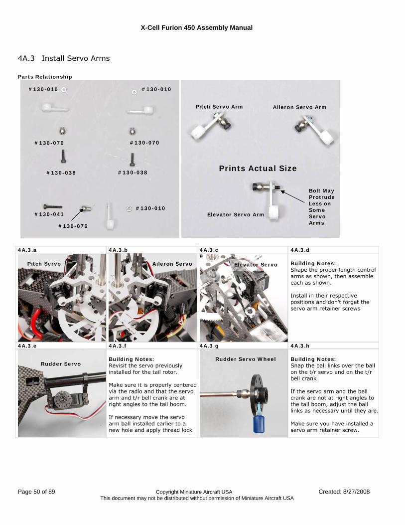
4A.3 Install Servo Arms Parts Relationship
4A.3.a 4A.3.b 4A.3.c 4A.3.d
Building Notes: Shape the proper length control arms as shown, then assemble each as shown. Install in their respective positions and don’t forget the servo arm retainer screws
4A.3.e 4A.3.f 4A.3.g 4A.3.h Building Notes: Revisit the servo previously installed for the tail rotor. Make sure it is properly centered via the radio and that the servo arm and t/r bell crank are at right angles to the tail boom. If necessary move the servo arm ball installed earlier to a new hole and apply thread lock
Building Notes: Snap the ball links over the ball on the t/r servo and on the t/r bell crank If the servo arm and the bell crank are not at right angles to the tail boom, adjust the ball links as necessary until they are. Make sure you have installed a servo arm retainer screw.
#130-076
#130-010
#130-038 #130-038
#130-041
#130-070 #130-070
#130-010 #130-010
Pitch Servo Arm Aileron Servo Arm
Elevator Servo Arm
Pitch Servo Aileron Servo Elevator Servo
Rudder Servo
Rudder Servo Wheel
Prints Actual Size
Bolt May Protrude Less on Some Servo Arms
X-Cell Furion 450 Assembly Manual
Created: 8/27/2008 Copyright Miniature Aircraft USA Page 51 of 89 This document may not be distributed without permission of Miniature Aircraft USA
4A.3.i 4A.3.j 4A.3.k
4A.4 Assemble Cyclic Control Rods Parts Relationship
Building Notes: Assemble three cyclic control rods as shown. These will print ACTUAL SIZE so you can lay them on the phototo determine the correct length All “actual size” rod lengths in this manual assume you are using the exact servos shown. Use of different servos may require minor adjustments to obtain the proper settings due to minor differences in servo dimensions. The final length will be within the ranges listed.
.638” thru .734”
#130-084 (3)
#130-090 (6)
Prints Actual Size
90° Angle
90° Angle
X-Cell Furion 450 Assembly Manual
Page 52 of 89 Copyright Miniature Aircraft USA Created: 8/27/2008 This document may not be distributed without permission of Miniature Aircraft USA
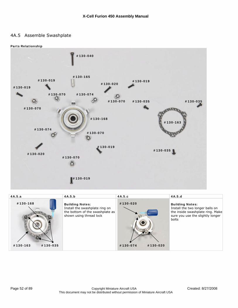
4A.5 Assemble Swashplate Parts Relationship
4A.5.a 4A.5.b 4A.5.c 4A.5.d
Building Notes: Install the swashplate ring on the bottom of the swashplate as shown using thread lock
Building Notes: Install the two longer balls on the inside swashplate ring. Make sure you use the slightly longer bolts
#130-019
#130-019
#130-019
#130-019
#130-019
#130-020
#130-020
#130-040
#130-070
#130-070
#130-070
#130-070
#130-070
#130-074
#130-074
#130-165
#130-035
#130-035 #130-035
#130-163 #130-168
#130-168
#130-163 #130-035 #130-074 #130-020
#130-020
X-Cell Furion 450 Assembly Manual
Created: 8/27/2008 Copyright Miniature Aircraft USA Page 53 of 89 This document may not be distributed without permission of Miniature Aircraft USA
4A.5.e 4A.5.f 4A.5.g 4A.5.h
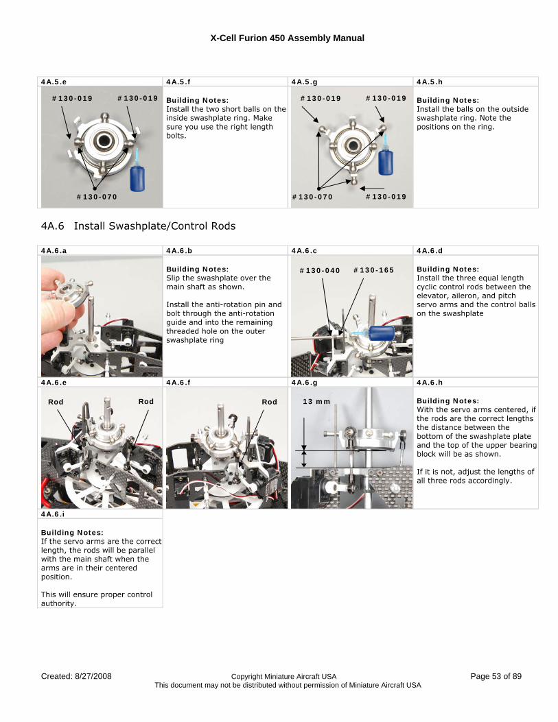
Building Notes: Install the two short balls on the inside swashplate ring. Make sure you use the right length bolts.
Building Notes: Install the balls on the outside swashplate ring. Note the positions on the ring.
4A.6 Install Swashplate/Control Rods 4A.6.a 4A.6.b 4A.6.c 4A.6.d
Building Notes: Slip the swashplate over the main shaft as shown. Install the anti-rotation pin and bolt through the anti-rotation guide and into the remaining threaded hole on the outer swashplate ring
Building Notes: Install the three equal length cyclic control rods between the elevator, aileron, and pitch servo arms and the control balls on the swashplate
4A.6.e 4A.6.f 4A.6.g 4A.6.h Building Notes: With the servo arms centered, if the rods are the correct lengths the distance between the bottom of the swashplate plate and the top of the upper bearing block will be as shown. If it is not, adjust the lengths of all three rods accordingly.
4A.6.i Building Notes: If the servo arms are the correct length, the rods will be parallel with the main shaft when the arms are in their centered position. This will ensure proper control authority.
#130-070
#130-019 #130-019
#130-019
#130-070
#130-019
#130-019
#130-040 #130-165
Rod Rod Rod 13 mm
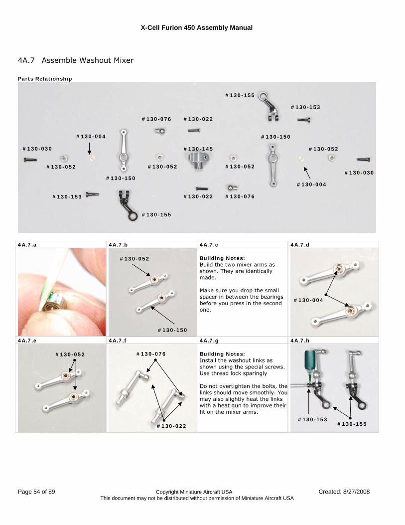
X-Cell Furion 450 Assembly Manual
Page 54 of 89 Copyright Miniature Aircraft USA Created: 8/27/2008 This document may not be distributed without permission of Miniature Aircraft USA
4A.7 Assemble Washout Mixer Parts Relationship
4A.7.a 4A.7.b 4A.7.c 4A.7.d
Building Notes: Build the two mixer arms as shown. They are identically made. Make sure you drop the small spacer in between the bearings before you press in the second one.
4A.7.e 4A.7.f 4A.7.g 4A.7.h Building Notes: Install the washout links as shown using the special screws. Use thread lock sparingly Do not overtighten the bolts, the links should move smoothly. You may also slightly heat the links with a heat gun to improve their fit on the mixer arms.
#130-145
#130-150
#130-150
#130-155
#130-155
#130-030
#130-030
#130-052
#130-052
#130-153
#130-153
#130-004
#130-004
#130-076 #130-022
#130-022 #130-076
#130-052 #130-052
#130-004
#130-150
#130-052
#130-052 #130-076
#130-022 #130-153
#130-155
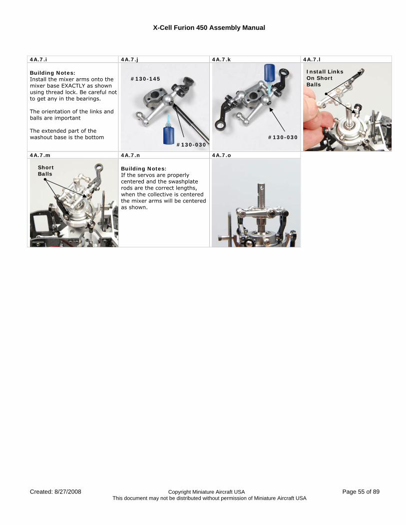
X-Cell Furion 450 Assembly Manual
Created: 8/27/2008 Copyright Miniature Aircraft USA Page 55 of 89 This document may not be distributed without permission of Miniature Aircraft USA
4A.7.i 4A.7.j 4A.7.k 4A.7.l Building Notes: Install the mixer arms onto the mixer base EXACTLY as shown using thread lock. Be careful not to get any in the bearings. The orientation of the links and balls are important The extended part of the washout base is the bottom
4A.7.m 4A.7.n 4A.7.o
Building Notes: If the servos are properly centered and the swashplate rods are the correct lengths, when the collective is centered the mixer arms will be centered as shown.
#130-145
#130-030 #130-030
Install Links On Short Balls
Short Balls
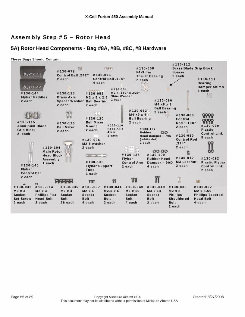
X-Cell Furion 450 Assembly Manual
Page 56 of 89 Copyright Miniature Aircraft USA Created: 8/27/2008 This document may not be distributed without permission of Miniature Aircraft USA
Assembly Step #5 – Rotor Head
5A) Rotor Head Components - Bag #8A, #8B, #8C, #8 Hardware These Bags Should Contain:
#130-144 Flybar Paddles 2 each
#130-062 M4 x9 x 4 Ball Bearing 2 each
#130-052 M2 x 5 x 2.5 Ball Bearing 7 each
#130-078 Control Ball .242” 2 each
#130-076 Control Ball .198” 4 each
#130-113 Brass Axle Spacer Washer 2 each
#130-004 M2 x .150” x .020” Shim Washer 2 each
#130-068 F4-9mm Thrust Bearing 2 each
#130-092 Plastic Flybar Control Link 2 each
#130-104 Main Rotor Head Block Assembly 1 each #130-130
Flybar Support Tube 1 each
#130-140 Flybar Control Bar 2 each
#130-120 Bell Mixer Mount 2 each
#130-125 Bell Mixer 2 each
#130-060 M4 x8 x 3 Ball Bearing 2 each
#130-080 Control Rod .374” 2 each
#130-086 Control Rod 1.198” 2 each #130-090
Plastic Control Link 8 each
#130-107 Rubber Head Damper – 70D (white dot) 2 each
#130-109 Rubber Head Damper – 90D 4 each
#130-110 Head Axle 4mm 1 each
#130-111 Bearing Damper Shims 4 each
#130-112 Brass Blade Grip Block Spacer 2 each
#130-115 Aluminum Blade Grip Block 2 each
#130-135 Flybar Control Arm 2 each
#130-006 M2.5 washer 2 each
#130-012 M3 Locknut 2 each
#130-014 M2 x 3 Phillips Flat Head Bolt 2 each
#130-022 M2 x 8.50 Phillips Tapered Head Bolt 4 each
#130-030 M2 x 8 Phillips Shouldered Bolt 2 each
#130-032 M3 x 3 Socket Set Screw 2 each
#130-035 M2 x 4 Socket Bolt 26 each
#130-037 M2 x 6 Socket Bolt 4 each
#130-040 M2 x 10 Socket Bolt 4 each
#130-044 M2.5 x 6 Socket Bolt 2 each
#130-049 M3 x 14 Socket Bolt 2 each
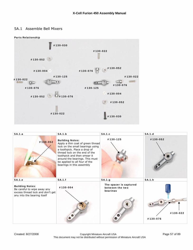
X-Cell Furion 450 Assembly Manual
Created: 8/27/2008 Copyright Miniature Aircraft USA Page 57 of 89 This document may not be distributed without permission of Miniature Aircraft USA
5A.1 Assemble Bell Mixers Parts Relationship
5A.1.a 5A.1.b 5A.1.c 5A.1.d
Building Notes: Apply a thin coat of green thread lock on the small bearings using a toothpick. Place a drop of thread lock on the end of the toothpick and then smear it around the bearings. This must be applied to all four of the bearings in this assembly
5A.1.e 5A.1.f 5A.1.g 5A.1.h Building Notes: Be careful to wipe away any excess thread lock and don’t get any into the bearing itself
#130-030
#130-030
#130-022
#130-022
#130-052
#130-052
#130-052
#130-052
#130-076
#130-076 #130-076
#130-076 #130-004
#130-004
#130-125
#130-125
#130-022 #130-022
#130-052 #130-052 #130-125
#130-004 The spacer is captured between the two bearings
#130-076
#130-022
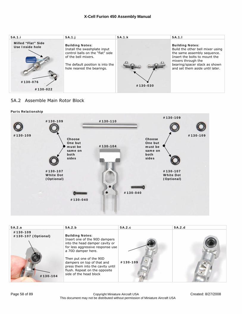
X-Cell Furion 450 Assembly Manual
Page 58 of 89 Copyright Miniature Aircraft USA Created: 8/27/2008 This document may not be distributed without permission of Miniature Aircraft USA
5A.1.i 5A.1.j 5A.1.k 5A.1.l
Building Notes: Install the swashplate input control balls on the “flat” side of the bell mixers. The default position is into the hole nearest the bearings.
Building Notes: Build the other bell mixer using the same assembly sequence. Insert the bolts to mount the mixers through the bearing/spacer stack as shown and set them aside until later.
5A.2 Assemble Main Rotor Block Parts Relationship
5A.2.a 5A.2.b 5A.2.c 5A.2.d
Building Notes: Insert one of the 90D dampers into the head damper cavity or for less aggressive response use a 70D damper here. Then put one of the 90D dampers on top of that and press them into the cavity until flush. Repeat on the opposite side of the head block
#130-110 #130-109
#130-109
#130-040
#130-040
#130-109
#130-104
#130-109
#130-104
#130-107 (Optional)
#130-109
#130-076
#130-022 #130-030
Milled “Flat” Side Use Inside hole
#130-107 White Dot (Optional)
#130-107 White Dot (Optional)
#130-109
Choose One but must be same on both sides
Choose One but must be same on both sides
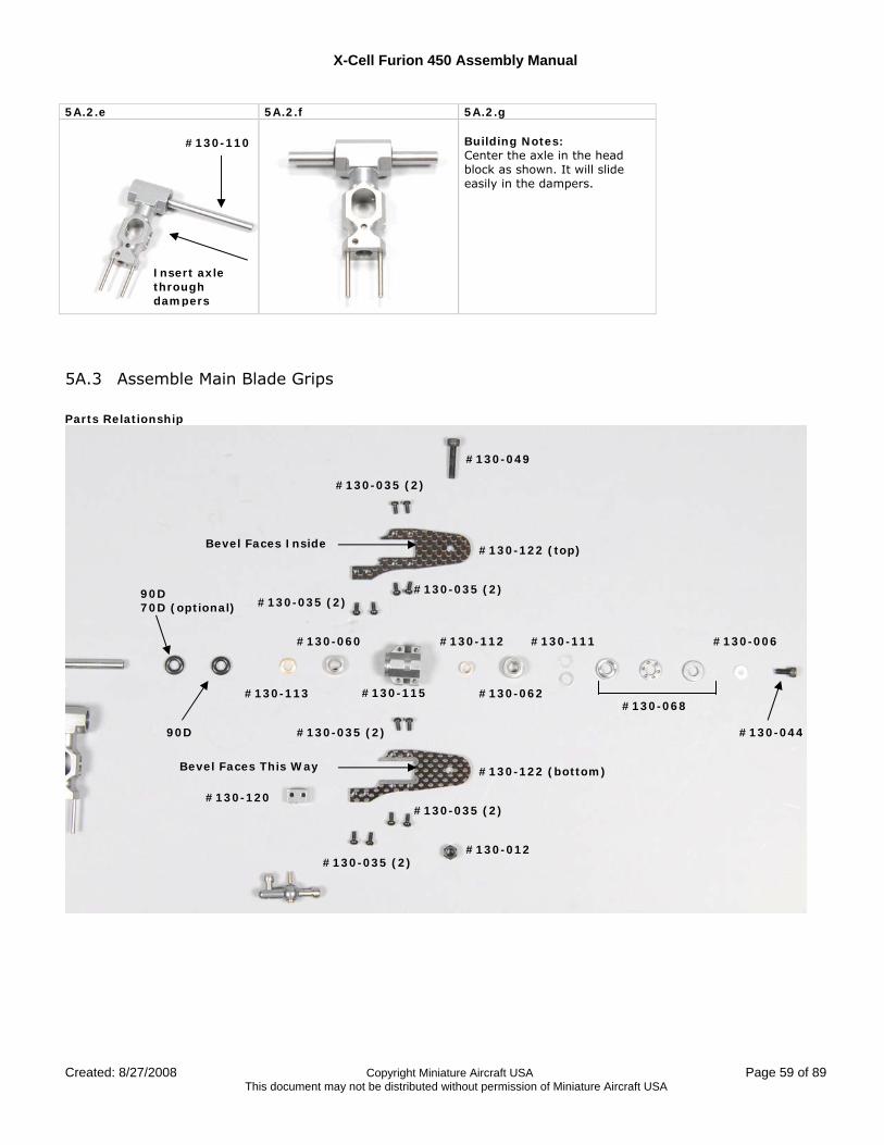
X-Cell Furion 450 Assembly Manual
Created: 8/27/2008 Copyright Miniature Aircraft USA Page 59 of 89 This document may not be distributed without permission of Miniature Aircraft USA
5A.2.e 5A.2.f 5A.2.g Building Notes: Center the axle in the head block as shown. It will slide easily in the dampers.
5A.3 Assemble Main Blade Grips Parts Relationship
#130-035 (2)
#130-035 (2) #130-035 (2)
#130-122 (top)
#130-122 (bottom)
#130-035 (2)
#130-035 (2)
#130-035 (2)
#130-049
#130-012
#130-113
#130-060
#130-115
#130-112
#130-062
#130-111
#130-068
#130-120
#130-006
#130-044
90D 70D (optional)
90D
Bevel Faces This Way
Bevel Faces Inside
#130-110
Insert axle through dampers
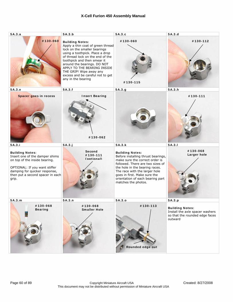
X-Cell Furion 450 Assembly Manual
Page 60 of 89 Copyright Miniature Aircraft USA Created: 8/27/2008 This document may not be distributed without permission of Miniature Aircraft USA
5A.3.a 5A.3.b 5A.3.c 5A.3.d
Building Notes: Apply a thin coat of green thread lock on the smaller bearings using a toothpick. Place a drop of thread lock on the end of the toothpick and then smear it around the bearings. DO NOT APPLY TO THE BEARING INSIDE THE GRIP! Wipe away any excess and be careful not to get any in the bearing
5A.3.e 5A.3.f 5A.3.g 5A.3.h
5A.3.i 5A.3.j 5A.3.k 5A.3.l Building Notes: Insert one of the damper shims on top of the inside bearing. OPTIONAL: If you want stiffer damping for quicker response, then put a second spacer in each grip.
Building Notes: Before installing thrust bearings, make sure the correct order is followed. There are two sizes of the hole in the bearing races. The race with the larger hole goes in first. Make sure the orientation of each bearing part matches the photos.
5A.3.m 5A.3.n 5A.3.o 5A.3.p
Building Notes: Install the axle spacer washers so that the rounded edge faces outward
#130-060 #130-060
#130-115
#130-112
Spacer goes in recess
#130-062
Insert Bearing #130-111
Second #130-111 (optional)
#130-068 Larger hole
#130-068 Bearing
#130-068 Smaller Hole
#130-113
Rounded edge out
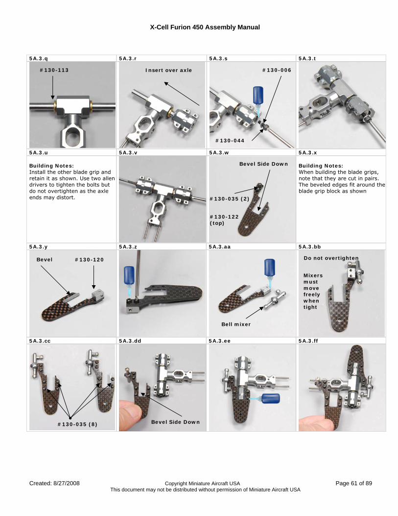
X-Cell Furion 450 Assembly Manual
Created: 8/27/2008 Copyright Miniature Aircraft USA Page 61 of 89 This document may not be distributed without permission of Miniature Aircraft USA
5A.3.q 5A.3.r 5A.3.s 5A.3.t
5A.3.u 5A.3.v 5A.3.w 5A.3.x Building Notes: Install the other blade grip and retain it as shown. Use two allen drivers to tighten the bolts but do not overtighten as the axle ends may distort.
Building Notes: When building the blade grips, note that they are cut in pairs. The beveled edges fit around the blade grip block as shown
5A.3.y 5A.3.z 5A.3.aa 5A.3.bb
5A.3.cc 5A.3.dd 5A.3.ee 5A.3.ff
#130-113 Insert over axle
#130-044
#130-006
#130-122 (top)
#130-035 (2)
Bevel #130-120
Bell mixer
#130-035 (8)
Bevel Side Down
Bevel Side Down
Do not overtighten
Mixers must move freely when tight
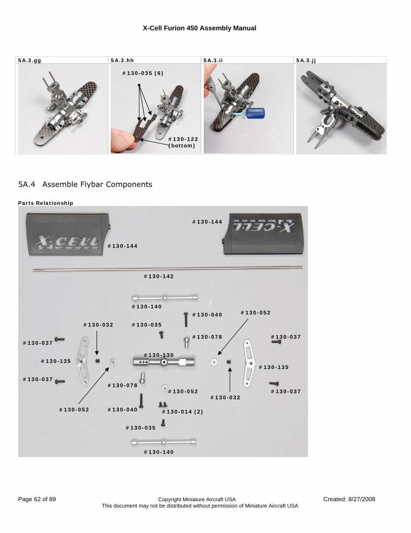
X-Cell Furion 450 Assembly Manual
Page 62 of 89 Copyright Miniature Aircraft USA Created: 8/27/2008 This document may not be distributed without permission of Miniature Aircraft USA
5A.3.gg 5A.3.hh 5A.3.ii 5A.3.jj
5A.4 Assemble Flybar Components Parts Relationship
#130-144
#130-144
#130-142
#130-140
#130-140
#130-040
#130-040
#130-035
#130-035
#130-078
#130-078 #130-052
#130-037
#130-037
#130-037
#130-037
#130-135 #130-135
#130-130
#130-032
#130-032
#130-052
#130-052
#130-035 (6)
#130-122 (bottom)
#130-014 (2)
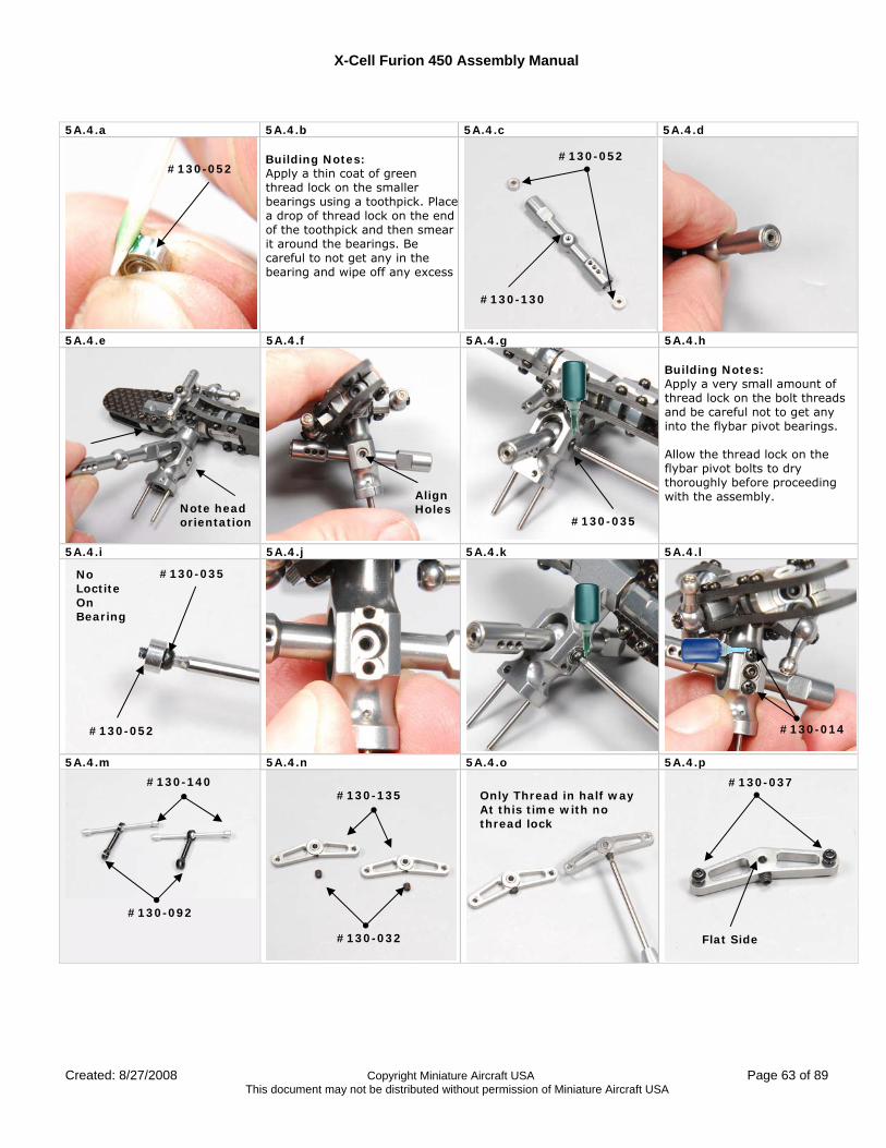
X-Cell Furion 450 Assembly Manual
Created: 8/27/2008 Copyright Miniature Aircraft USA Page 63 of 89 This document may not be distributed without permission of Miniature Aircraft USA
5A.4.a 5A.4.b 5A.4.c 5A.4.d
Building Notes: Apply a thin coat of green thread lock on the smaller bearings using a toothpick. Placea drop of thread lock on the end of the toothpick and then smear it around the bearings. Be careful to not get any in the bearing and wipe off any excess
5A.4.e 5A.4.f 5A.4.g 5A.4.h
Building Notes: Apply a very small amount of thread lock on the bolt threads and be careful not to get any into the flybar pivot bearings. Allow the thread lock on the flybar pivot bolts to dry thoroughly before proceeding with the assembly.
5A.4.i 5A.4.j 5A.4.k 5A.4.l
5A.4.m 5A.4.n 5A.4.o 5A.4.p
#130-052 #130-052
#130-130
Align Holes
#130-035
#130-035
#130-052
No Loctite On Bearing
#130-014
#130-140
#130-092
#130-135
#130-032
Only Thread in half way At this time with no thread lock
#130-037
Note head orientation
Flat Side
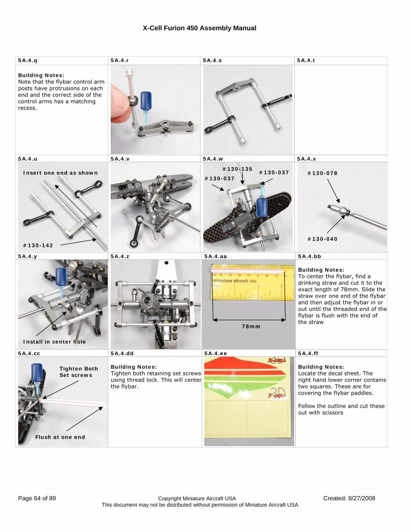
X-Cell Furion 450 Assembly Manual
Page 64 of 89 Copyright Miniature Aircraft USA Created: 8/27/2008 This document may not be distributed without permission of Miniature Aircraft USA
5A.4.q 5A.4.r 5A.4.s 5A.4.t
Building Notes: Note that the flybar control arm posts have protrusions on each end and the correct side of the control arms has a matching recess.
5A.4.u 5A.4.v 5A.4.w 5A.4.x
5A.4.y 5A.4.z 5A.4.aa 5A.4.bb
Building Notes: To center the flybar, find a drinking straw and cut it to the exact length of 78mm. Slide the straw over one end of the flybar and then adjust the flybar in or out until the threaded end of the flybar is flush with the end of the straw
5A.4.cc 5A.4.dd 5A.4.ee 5A.4.ff Building Notes: Tighten both retaining set screws using thread lock. This will centerthe flybar.
Building Notes: Locate the decal sheet. The right hand lower corner contains two squares. These are for covering the flybar paddles. Follow the outline and cut these out with scissors
Insert one end as shown
#130-142
#130-135
#130-037 #130-037 #130-078
#130-040
Install in center hole
Flush at one end
78mm
Tighten Both Set screws
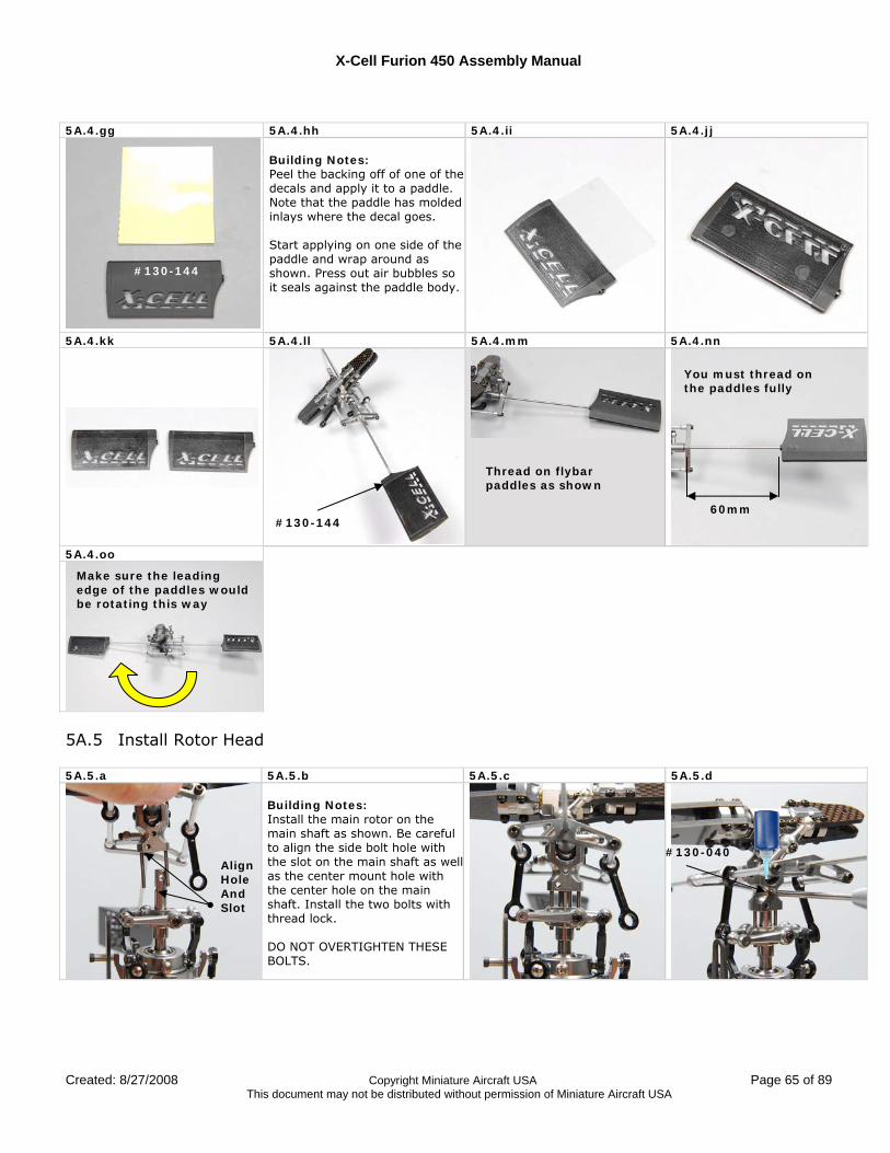
X-Cell Furion 450 Assembly Manual
Created: 8/27/2008 Copyright Miniature Aircraft USA Page 65 of 89 This document may not be distributed without permission of Miniature Aircraft USA
5A.4.gg 5A.4.hh 5A.4.ii 5A.4.jj
Building Notes: Peel the backing off of one of the decals and apply it to a paddle. Note that the paddle has molded inlays where the decal goes. Start applying on one side of the paddle and wrap around as shown. Press out air bubbles so it seals against the paddle body.
5A.4.kk 5A.4.ll 5A.4.mm 5A.4.nn
5A.4.oo
5A.5 Install Rotor Head 5A.5.a 5A.5.b 5A.5.c 5A.5.d
Building Notes: Install the main rotor on the main shaft as shown. Be careful to align the side bolt hole with the slot on the main shaft as wellas the center mount hole with the center hole on the main shaft. Install the two bolts with thread lock. DO NOT OVERTIGHTEN THESE BOLTS.
Align Hole And Slot
#130-040
#130-144
Thread on flybar paddles as shown
#130-144 60mm
You must thread on the paddles fully
Make sure the leading edge of the paddles would be rotating this way
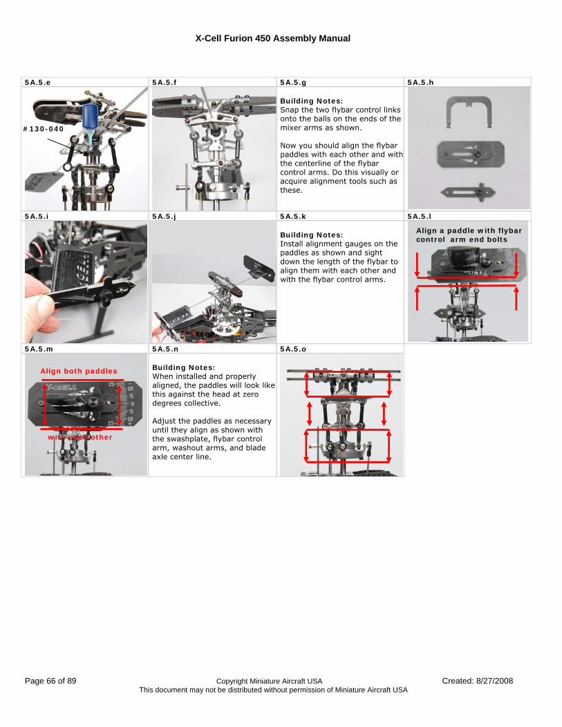
X-Cell Furion 450 Assembly Manual
Page 66 of 89 Copyright Miniature Aircraft USA Created: 8/27/2008 This document may not be distributed without permission of Miniature Aircraft USA
5A.5.e 5A.5.f 5A.5.g 5A.5.h
Building Notes: Snap the two flybar control links onto the balls on the ends of the mixer arms as shown. Now you should align the flybar paddles with each other and with the centerline of the flybar control arms. Do this visually or acquire alignment tools such as these.
5A.5.i 5A.5.j 5A.5.k 5A.5.l
Building Notes: Install alignment gauges on the paddles as shown and sight down the length of the flybar to align them with each other and with the flybar control arms.
5A.5.m 5A.5.n 5A.5.o
Building Notes: When installed and properly aligned, the paddles will look like this against the head at zero degrees collective. Adjust the paddles as necessary until they align as shown with the swashplate, flybar control arm, washout arms, and blade axle center line.
#130-040
Align a paddle with flybar control arm end bolts
Align both paddles
with each other
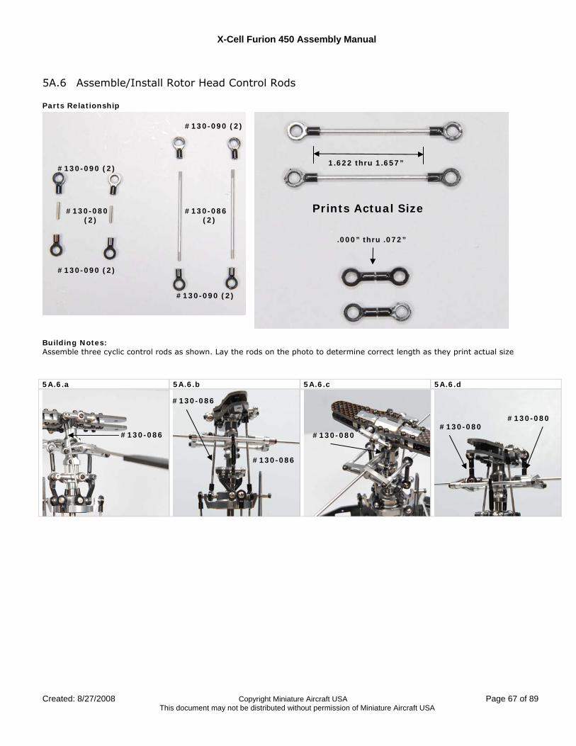
X-Cell Furion 450 Assembly Manual
Created: 8/27/2008 Copyright Miniature Aircraft USA Page 67 of 89 This document may not be distributed without permission of Miniature Aircraft USA
5A.6 Assemble/Install Rotor Head Control Rods Parts Relationship
Building Notes: Assemble three cyclic control rods as shown. Lay the rods on the photo to determine correct length as they print actual size 5A.6.a 5A.6.b 5A.6.c 5A.6.d
#130-086
#130-086
#130-086
#130-080 #130-080
#130-080
#130-086 (2)
#130-080 (2)
#130-090 (2)
#130-090 (2)
#130-090 (2)
#130-090 (2)
1.622 thru 1.657”
Prints Actual Size
.000” thru .072”
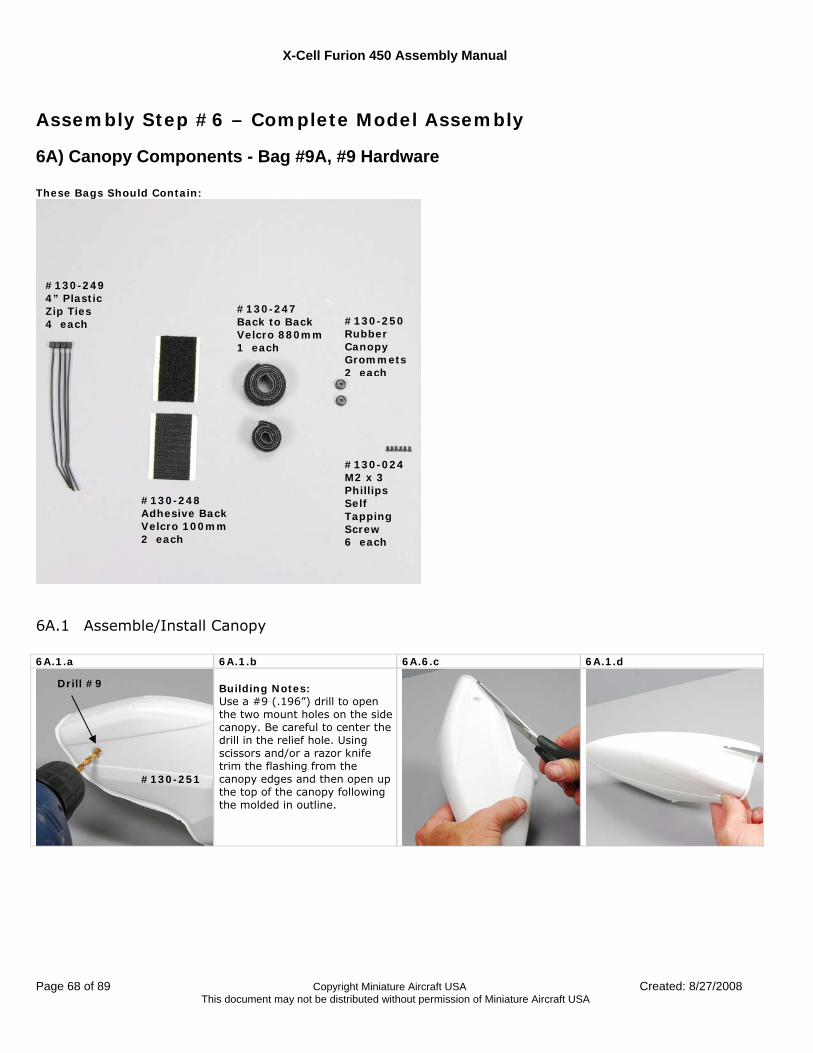
X-Cell Furion 450 Assembly Manual
Page 68 of 89 Copyright Miniature Aircraft USA Created: 8/27/2008 This document may not be distributed without permission of Miniature Aircraft USA
Assembly Step #6 – Complete Model Assembly
6A) Canopy Components - Bag #9A, #9 Hardware These Bags Should Contain:
6A.1 Assemble/Install Canopy 6A.1.a 6A.1.b 6A.6.c 6A.1.d
Building Notes: Use a #9 (.196”) drill to open the two mount holes on the side canopy. Be careful to center the drill in the relief hole. Using scissors and/or a razor knife trim the flashing from the canopy edges and then open up the top of the canopy following the molded in outline.
#130-249 4” Plastic Zip Ties 4 each
#130-248 Adhesive Back Velcro 100mm 2 each
#130-247 Back to Back Velcro 880mm 1 each
#130-250 Rubber Canopy Grommets 2 each
#130-024 M2 x 3 Phillips Self Tapping Screw 6 each
#130-251
Drill #9
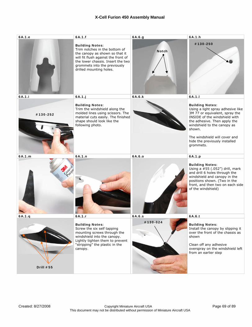
X-Cell Furion 450 Assembly Manual
Created: 8/27/2008 Copyright Miniature Aircraft USA Page 69 of 89 This document may not be distributed without permission of Miniature Aircraft USA
6A.1.e 6A.1.f 6A.6.g 6A.1.h
Building Notes: Trim notches in the bottom of the canopy as shown so that it will fit flush against the front of the lower chassis. Insert the two grommets into the previously drilled mounting holes.
6A.1.i 6A.1.j 6A.6.k 6A.1.l
Building Notes: Trim the windshield along the molded lines using scissors. The material cuts easily. The finished shape should look like the following photo.
Building Notes: Using a light spray adhesive like 3M 77 or equivalent, spray the INSIDE of the windshield with the adhesive. Then apply the windshield to the canopy as shown. The windshield will cover and hide the previously installed grommets.
6A.1.m 6A.1.n 6A.6.o 6A.1.p
Building Notes: Using a #55 (.052”) drill, mark and drill 6 holes through the windshield and canopy in the positions shown. (Two in the front, and then two on each side of the windshield)
6A.1.q 6A.1.r 6A.6.s 6A.6.t Building Notes: Screw the six self tapping mounting screws through the windshield into the canopy. Lightly tighten them to prevent “stripping” the plastic in the canopy.
Building Notes: Install the canopy by slipping it over the front of the chassis as shown Clean off any adhesive overspray on the windshield left from an earlier step
Notch
#130-250
#130-252
Drill #55
#130-024
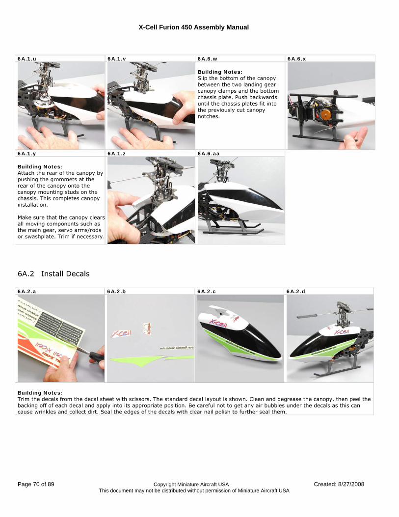
X-Cell Furion 450 Assembly Manual
Page 70 of 89 Copyright Miniature Aircraft USA Created: 8/27/2008 This document may not be distributed without permission of Miniature Aircraft USA
6A.1.u 6A.1.v 6A.6.w 6A.6.x
Building Notes: Slip the bottom of the canopy between the two landing gear canopy clamps and the bottom chassis plate. Push backwards until the chassis plates fit into the previously cut canopy notches.
6A.1.y 6A.1.z 6A.6.aa Building Notes: Attach the rear of the canopy by pushing the grommets at the rear of the canopy onto the canopy mounting studs on the chassis. This completes canopy installation. Make sure that the canopy clearsall moving components such as the main gear, servo arms/rods or swashplate. Trim if necessary.
6A.2 Install Decals 6A.2.a 6A.2.b 6A.2.c 6A.2.d
Building Notes: Trim the decals from the decal sheet with scissors. The standard decal layout is shown. Clean and degrease the canopy, then peel the backing off of each decal and apply into its appropriate position. Be careful not to get any air bubbles under the decals as this can cause wrinkles and collect dirt. Seal the edges of the decals with clear nail polish to further seal them.
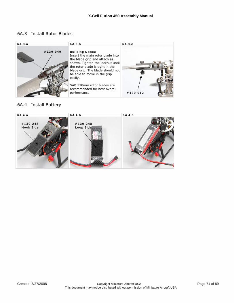
X-Cell Furion 450 Assembly Manual
Created: 8/27/2008 Copyright Miniature Aircraft USA Page 71 of 89 This document may not be distributed without permission of Miniature Aircraft USA
6A.3 Install Rotor Blades 6A.3.a 6A.3.b 6A.3.c
Building Notes: Insert the main rotor blade into the blade grip and attach as shown. Tighten the locknut until the rotor blade is tight in the blade grip. The blade should not be able to move in the grip easily. SAB 320mm rotor blades are recommended for best overall performance.
6A.4 Install Battery 6A.4.a 6A.4.b 6A.4.c
#130-049
#130-012
#130-248 Hook Side
#130-248 Loop Side
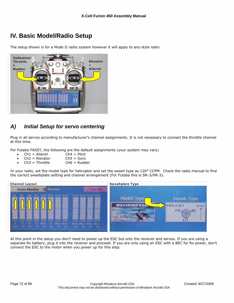
X-Cell Furion 450 Assembly Manual
Page 72 of 89 Copyright Miniature Aircraft USA Created: 8/27/2008 This document may not be distributed without permission of Miniature Aircraft USA
IV. Basic Model/Radio Setup The setup shown is for a Mode II radio system however it will apply to any style radio
A) Initial Setup for servo centering Plug in all servos according to manufacturer’s channel assignments. It is not necessary to connect the throttle channel at this time. For Futaba FASST, the following are the default assignments (your system may vary)
• Ch1 = Aileron Ch4 = Pitch • Ch2 = Elevator Ch5 = Gyro • Ch3 = Throttle Ch6 = Rudder
In your radio, set the model type for helicopter and set the swash type as 120° CCPM. Check the radio manual to find the correct swashplate setting and channel arrangement (For Futaba this is SR-3/HR-3). Channel Layout Swashplate Type
At this point in the setup you don’t need to power up the ESC but only the receiver and servos. If you are using a separate Rx battery, plug it into the receiver and proceed. If you are only using an ESC with a BEC for Rx power, don’t connect the ESC to the motor when you power up for this step.
Collective/ Throttle + Rudder
Elevator + Aileron
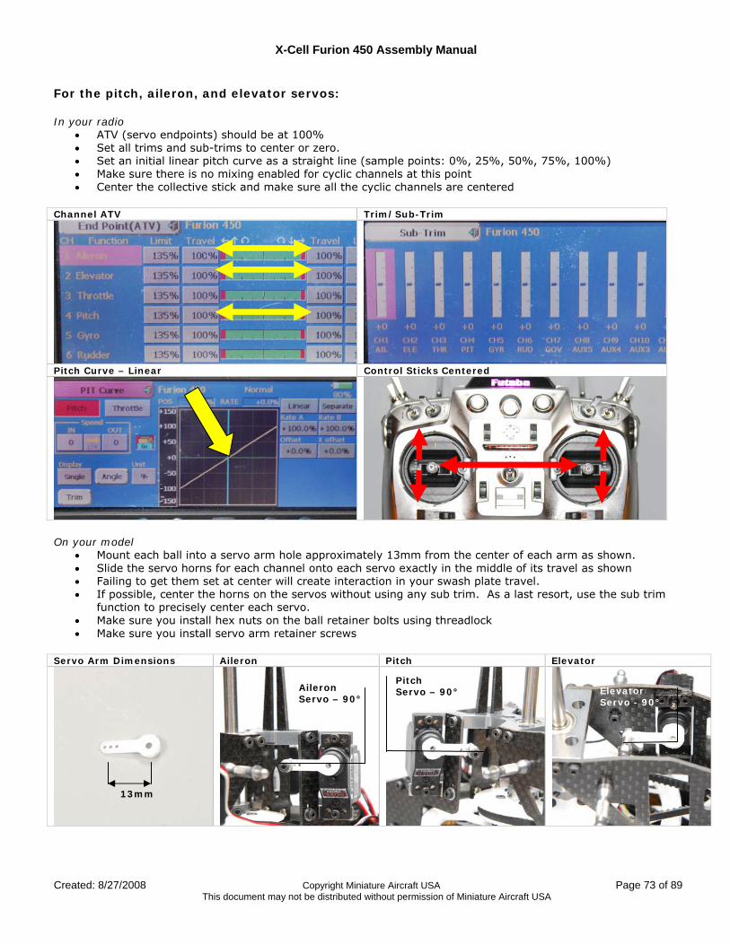
X-Cell Furion 450 Assembly Manual
Created: 8/27/2008 Copyright Miniature Aircraft USA Page 73 of 89 This document may not be distributed without permission of Miniature Aircraft USA
For the pitch, aileron, and elevator servos: In your radio
• ATV (servo endpoints) should be at 100% • Set all trims and sub-trims to center or zero. • Set an initial linear pitch curve as a straight line (sample points: 0%, 25%, 50%, 75%, 100%) • Make sure there is no mixing enabled for cyclic channels at this point • Center the collective stick and make sure all the cyclic channels are centered
Channel ATV Trim/Sub-Trim
Pitch Curve – Linear Control Sticks Centered
On your model
• Mount each ball into a servo arm hole approximately 13mm from the center of each arm as shown. • Slide the servo horns for each channel onto each servo exactly in the middle of its travel as shown • Failing to get them set at center will create interaction in your swash plate travel. • If possible, center the horns on the servos without using any sub trim. As a last resort, use the sub trim
function to precisely center each servo. • Make sure you install hex nuts on the ball retainer bolts using threadlock • Make sure you install servo arm retainer screws
Servo Arm Dimensions Aileron Pitch Elevator
13mm
Aileron Servo – 90°
Pitch Servo – 90° Elevator
Servo - 90°
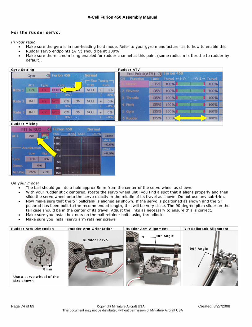
X-Cell Furion 450 Assembly Manual
Page 74 of 89 Copyright Miniature Aircraft USA Created: 8/27/2008 This document may not be distributed without permission of Miniature Aircraft USA
For the rudder servo: In your radio
• Make sure the gyro is in non-heading hold mode. Refer to your gyro manufacturer as to how to enable this. • Rudder servo endpoints (ATV) should be at 100% • Make sure there is no mixing enabled for rudder channel at this point (some radios mix throttle to rudder by
default).
Gyro Setting Rudder ATV
Rudder Mixing
On your model
• The ball should go into a hole approx 8mm from the center of the servo wheel as shown. • With your rudder stick centered, rotate the servo wheel until you find a spot that it aligns properly and then
slide the servo wheel onto the servo exactly in the middle of its travel as shown. Do not use any sub-trim. • Now make sure that the t/r bellcrank is aligned as shown. If the servo is positioned as shown and the t/r
pushrod has been built to the recommended length, this will be very close. The 90 degree pitch slider on the tail case should be in the center of its travel. Adjust the links as necessary to ensure this is correct.
• Make sure you install hex nuts on the ball retainer bolts using threadlock • Make sure you install servo arm retainer screws
Rudder Arm Dimension Rudder Arm Orientation Rudder Arm Alignment T/R Bellcrank Alignment
Use a servo wheel of the size shown
8mm
Rudder Servo 90° Angle
90° Angle
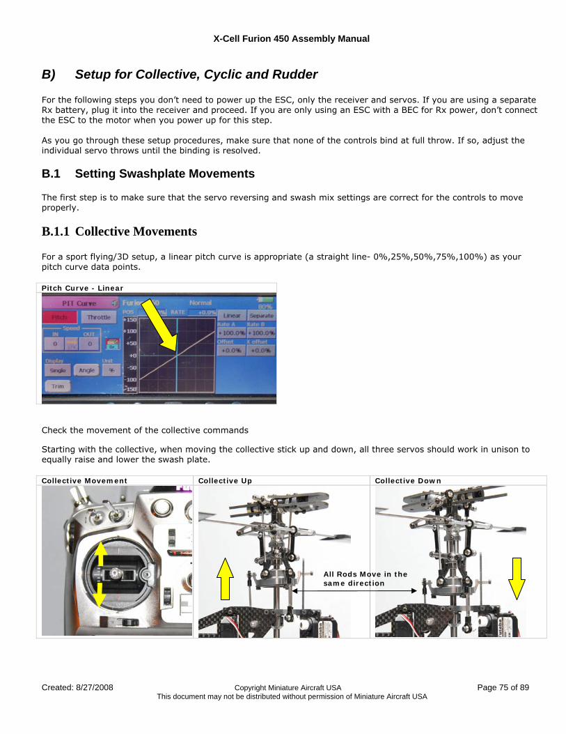
X-Cell Furion 450 Assembly Manual
Created: 8/27/2008 Copyright Miniature Aircraft USA Page 75 of 89 This document may not be distributed without permission of Miniature Aircraft USA
B) Setup for Collective, Cyclic and Rudder For the following steps you don’t need to power up the ESC, only the receiver and servos. If you are using a separate Rx battery, plug it into the receiver and proceed. If you are only using an ESC with a BEC for Rx power, don’t connect the ESC to the motor when you power up for this step. As you go through these setup procedures, make sure that none of the controls bind at full throw. If so, adjust the individual servo throws until the binding is resolved.
B.1 Setting Swashplate Movements The first step is to make sure that the servo reversing and swash mix settings are correct for the controls to move properly.
B.1.1 Collective Movements For a sport flying/3D setup, a linear pitch curve is appropriate (a straight line- 0%,25%,50%,75%,100%) as your pitch curve data points. Pitch Curve - Linear
Check the movement of the collective commands Starting with the collective, when moving the collective stick up and down, all three servos should work in unison to equally raise and lower the swash plate. Collective Movement Collective Up Collective Down
All Rods Move in the same direction
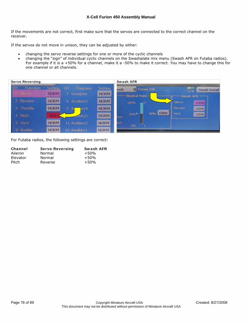
X-Cell Furion 450 Assembly Manual
Page 76 of 89 Copyright Miniature Aircraft USA Created: 8/27/2008 This document may not be distributed without permission of Miniature Aircraft USA
If the movements are not correct, first make sure that the servos are connected to the correct channel on the receiver. If the servos do not move in unison, they can be adjusted by either:
• changing the servo reverse settings for one or more of the cyclic channels • changing the “sign” of individual cyclic channels on the Swashplate mix menu (Swash AFR on Futaba radios).
For example if it is a +50% for a channel, make it a -50% to make it correct. You may have to change this for one channel or all channels.
Servo Reversing Swash AFR
For Futaba radios, the following settings are correct: Channel Servo Reversing Swash AFR Aileron Normal +50% Elevator Normal +50% Pitch Reverse +50%
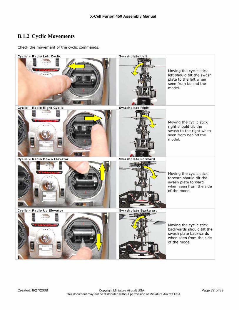
X-Cell Furion 450 Assembly Manual
Created: 8/27/2008 Copyright Miniature Aircraft USA Page 77 of 89 This document may not be distributed without permission of Miniature Aircraft USA
B.1.2 Cyclic Movements Check the movement of the cyclic commands. Cyclic – Radio Left Cyclic Swashplate Left
Moving the cyclic stick left should tilt the swash plate to the left when seen from behind the model.
Cyclic – Radio Right Cyclic Swashplate Right
Moving the cyclic stick right should tilt the swash to the right when seen from behind the model.
Cyclic – Radio Down Elevator Swashplate Forward
Moving the cyclic stick forward should tilt the swash plate forward when seen from the side of the model
Cyclic – Radio Up Elevator Swashplate Backward
Moving the cyclic stick backwards should tilt the swash plate backwards when seen from the side of the model
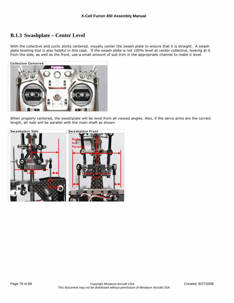
X-Cell Furion 450 Assembly Manual
Page 78 of 89 Copyright Miniature Aircraft USA Created: 8/27/2008 This document may not be distributed without permission of Miniature Aircraft USA
B.1.3 Swashplate – Center Level With the collective and cyclic sticks centered, visually center the swash plate to ensure that it is straight. A swash plate leveling tool is also helpful in this case. If the swash plate is not 100% level at center collective, looking at it from the side, as well as the front, use a small amount of sub trim in the appropriate channel to make it level. Collective Centered
When properly centered, the swashplate will be level from all viewed angles. Also, if the servo arms are the correct length, all rods will be parallel with the main shaft as shown Swashplate Side Swashplate Front
Level
Rod Is Parallel
Level
Rods Are Parallel
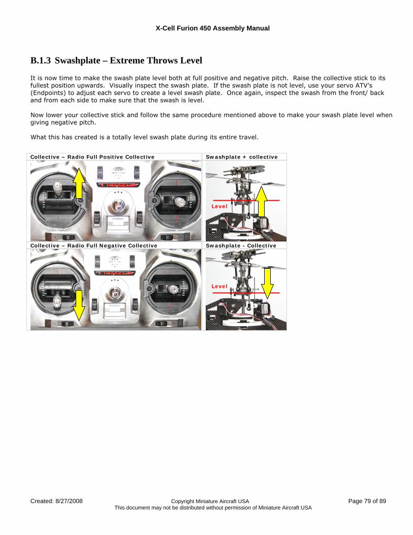
X-Cell Furion 450 Assembly Manual
Created: 8/27/2008 Copyright Miniature Aircraft USA Page 79 of 89 This document may not be distributed without permission of Miniature Aircraft USA
B.1.3 Swashplate – Extreme Throws Level It is now time to make the swash plate level both at full positive and negative pitch. Raise the collective stick to its fullest position upwards. Visually inspect the swash plate. If the swash plate is not level, use your servo ATV’s (Endpoints) to adjust each servo to create a level swash plate. Once again, inspect the swash from the front/ back and from each side to make sure that the swash is level. Now lower your collective stick and follow the same procedure mentioned above to make your swash plate level when giving negative pitch. What this has created is a totally level swash plate during its entire travel.
Collective – Radio Full Positive Collective Swashplate + collective
Collective – Radio Full Negative Collective Swashplate - Collective
Level
Level
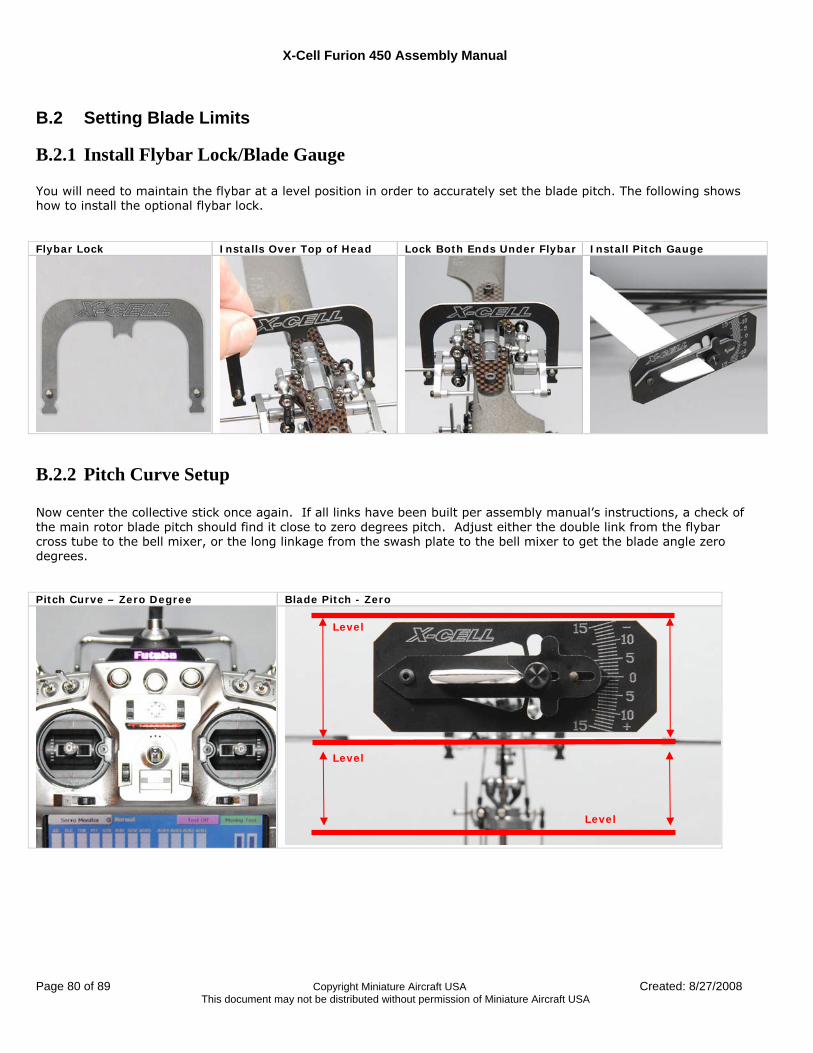
X-Cell Furion 450 Assembly Manual
Page 80 of 89 Copyright Miniature Aircraft USA Created: 8/27/2008 This document may not be distributed without permission of Miniature Aircraft USA
B.2 Setting Blade Limits
B.2.1 Install Flybar Lock/Blade Gauge You will need to maintain the flybar at a level position in order to accurately set the blade pitch. The following shows how to install the optional flybar lock. Flybar Lock Installs Over Top of Head Lock Both Ends Under Flybar Install Pitch Gauge
B.2.2 Pitch Curve Setup Now center the collective stick once again. If all links have been built per assembly manual’s instructions, a check of the main rotor blade pitch should find it close to zero degrees pitch. Adjust either the double link from the flybar cross tube to the bell mixer, or the long linkage from the swash plate to the bell mixer to get the blade angle zero degrees. Pitch Curve – Zero Degree Blade Pitch - Zero
Level
Level
Level
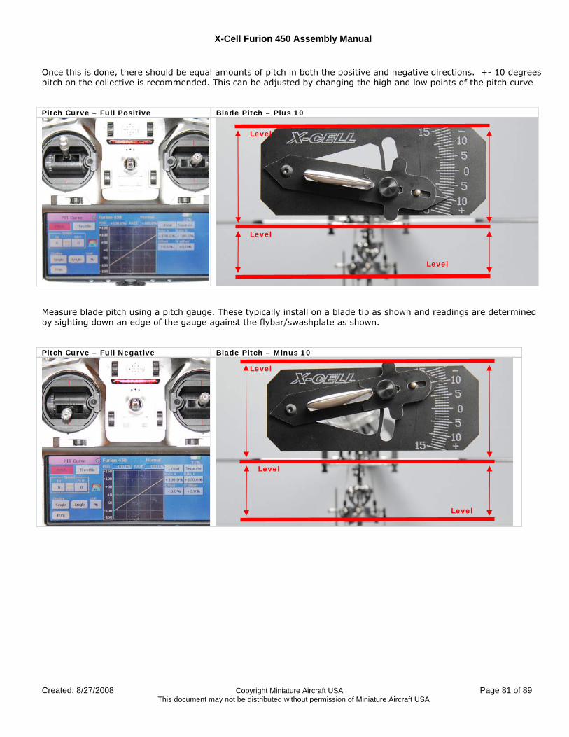
X-Cell Furion 450 Assembly Manual
Created: 8/27/2008 Copyright Miniature Aircraft USA Page 81 of 89 This document may not be distributed without permission of Miniature Aircraft USA
Once this is done, there should be equal amounts of pitch in both the positive and negative directions. +- 10 degrees pitch on the collective is recommended. This can be adjusted by changing the high and low points of the pitch curve Pitch Curve – Full Positive Blade Pitch – Plus 10
Measure blade pitch using a pitch gauge. These typically install on a blade tip as shown and readings are determined by sighting down an edge of the gauge against the flybar/swashplate as shown. Pitch Curve – Full Negative Blade Pitch – Minus 10
Level
Level
Level
Level
Level
Level
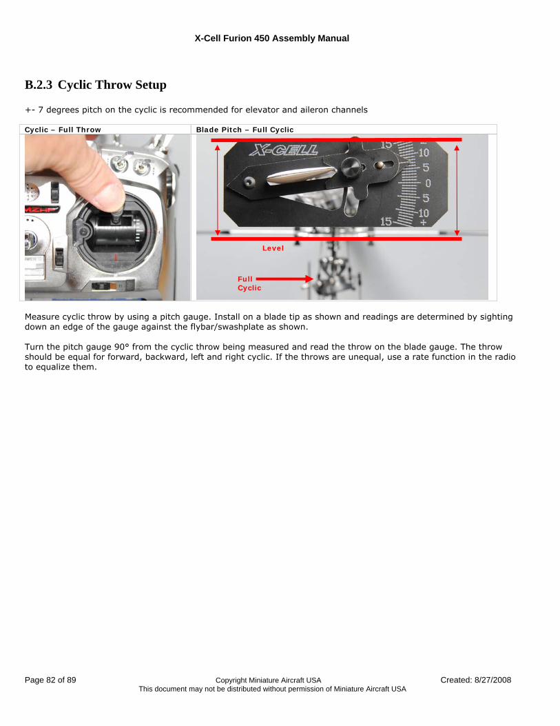
X-Cell Furion 450 Assembly Manual
Page 82 of 89 Copyright Miniature Aircraft USA Created: 8/27/2008 This document may not be distributed without permission of Miniature Aircraft USA
B.2.3 Cyclic Throw Setup +- 7 degrees pitch on the cyclic is recommended for elevator and aileron channels Cyclic – Full Throw Blade Pitch – Full Cyclic
Measure cyclic throw by using a pitch gauge. Install on a blade tip as shown and readings are determined by sighting down an edge of the gauge against the flybar/swashplate as shown. Turn the pitch gauge 90° from the cyclic throw being measured and read the throw on the blade gauge. The throw should be equal for forward, backward, left and right cyclic. If the throws are unequal, use a rate function in the radio to equalize them.
Level
Full Cyclic
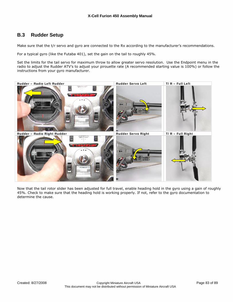
X-Cell Furion 450 Assembly Manual
Created: 8/27/2008 Copyright Miniature Aircraft USA Page 83 of 89 This document may not be distributed without permission of Miniature Aircraft USA
B.3 Rudder Setup Make sure that the t/r servo and gyro are connected to the Rx according to the manufacturer’s recommendations. For a typical gyro (like the Futaba 401), set the gain on the tail to roughly 45%. Set the limits for the tail servo for maximum throw to allow greater servo resolution. Use the Endpoint menu in the radio to adjust the Rudder ATV’s to adjust your pirouette rate (A recommended starting value is 100%) or follow the instructions from your gyro manufacturer. Rudder – Radio Left Rudder Rudder Servo Left T/R – Full Left
Rudder – Radio Right Rudder Rudder Servo Right T/R – Full Right
Now that the tail rotor slider has been adjusted for full travel, enable heading hold in the gyro using a gain of roughly 45%. Check to make sure that the heading hold is working properly. If not, refer to the gyro documentation to determine the cause.
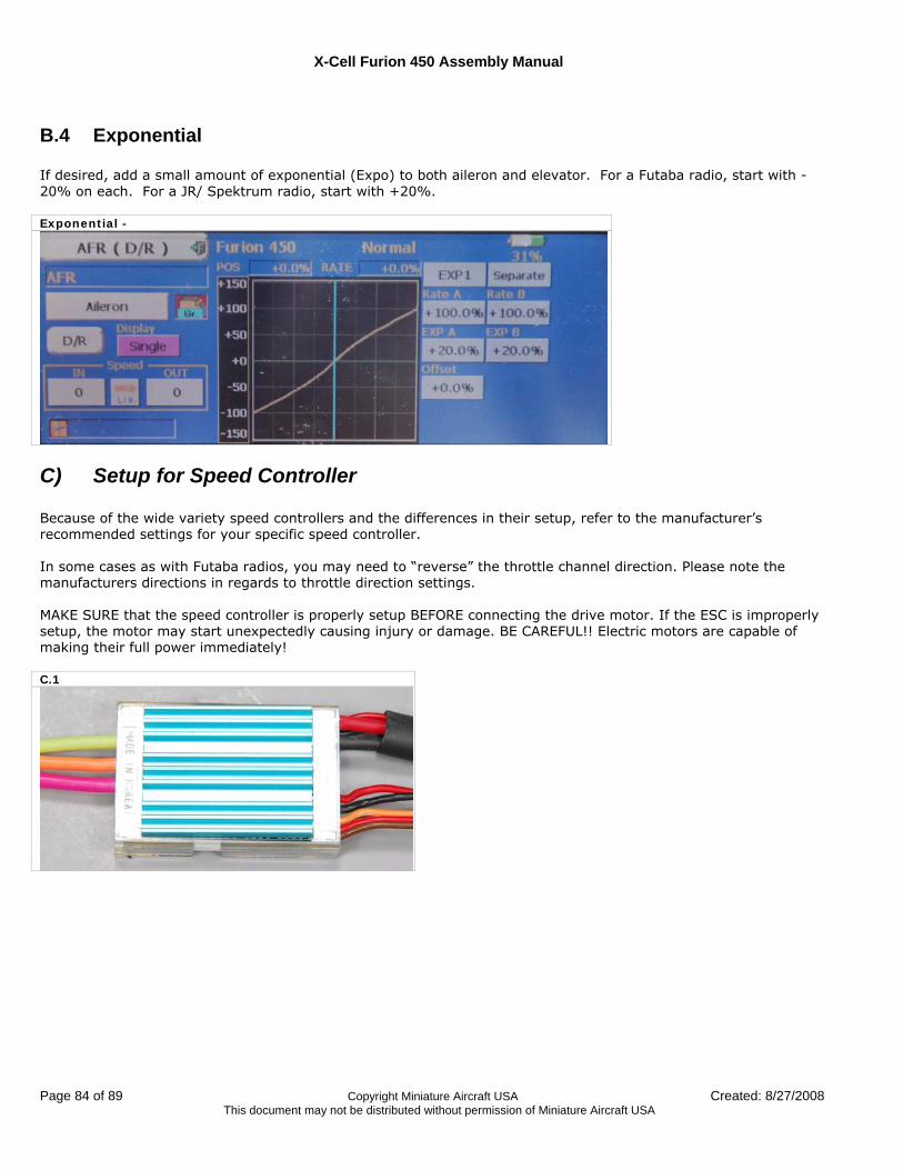
X-Cell Furion 450 Assembly Manual
Page 84 of 89 Copyright Miniature Aircraft USA Created: 8/27/2008 This document may not be distributed without permission of Miniature Aircraft USA
B.4 Exponential If desired, add a small amount of exponential (Expo) to both aileron and elevator. For a Futaba radio, start with -20% on each. For a JR/ Spektrum radio, start with +20%. Exponential -
C) Setup for Speed Controller Because of the wide variety speed controllers and the differences in their setup, refer to the manufacturer’s recommended settings for your specific speed controller. In some cases as with Futaba radios, you may need to “reverse” the throttle channel direction. Please note the manufacturers directions in regards to throttle direction settings. MAKE SURE that the speed controller is properly setup BEFORE connecting the drive motor. If the ESC is improperly setup, the motor may start unexpectedly causing injury or damage. BE CAREFUL!! Electric motors are capable of making their full power immediately! C.1
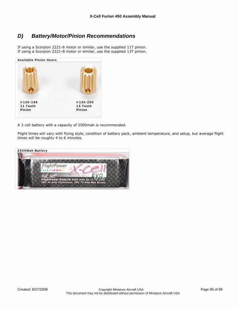
X-Cell Furion 450 Assembly Manual
Created: 8/27/2008 Copyright Miniature Aircraft USA Page 85 of 89 This document may not be distributed without permission of Miniature Aircraft USA
D) Battery/Motor/Pinion Recommendations If using a Scorpion 2221-6 motor or similar, use the supplied 11T pinion. If using a Scorpion 2221-8 motor or similar, use the supplied 13T pinion. Available Pinion Gears
A 3 cell battery with a capacity of 2500mah is recommended. Flight times will vary with flying style, condition of battery pack, ambient temperature, and setup, but average flight times will be roughly 4 to 6 minutes. 2500Mah Battery
#130-198 11 Tooth Pinion
#130-200 13 Tooth Pinion
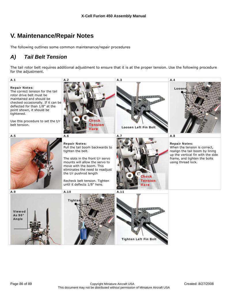
X-Cell Furion 450 Assembly Manual
Page 86 of 89 Copyright Miniature Aircraft USA Created: 8/27/2008 This document may not be distributed without permission of Miniature Aircraft USA
V. Maintenance/Repair Notes The following outlines some common maintenance/repair procedures
A) Tail Belt Tension The tail rotor belt requires additional adjustment to ensure that it is at the proper tension. Use the following procedure for the adjustment. A.1 A.2 A.3 A.4 Repair Notes: The correct tension for the tail rotor drive belt must be maintained and should be checked occasionally. If it can be deflected for than 1/8” at the point shown, it should be tightened. Use this procedure to set the t/r belt tension.
A.5 A.6 A.7 A.8
Repair Notes: Pull the tail boom backwards to tighten the belt. The slots in the front t/r servo mounts will allow the servo to move with the boom. This eliminates the need to readjust the t/r pushrod length Recheck belt tension. Tighten until it deflects 1/8” here.
Repair Notes: When the tension is correct, realign the tail boom by lining up the vertical fin with the side frame, and tighten the bolts using thread lock.
A.9 A.10 A.11
Loosen Left Fin Bolt
Loosen
Check Tension Here
Viewed As 90° Angle
Tighten Left Fin Bolt
Tighten
Check Tension Here
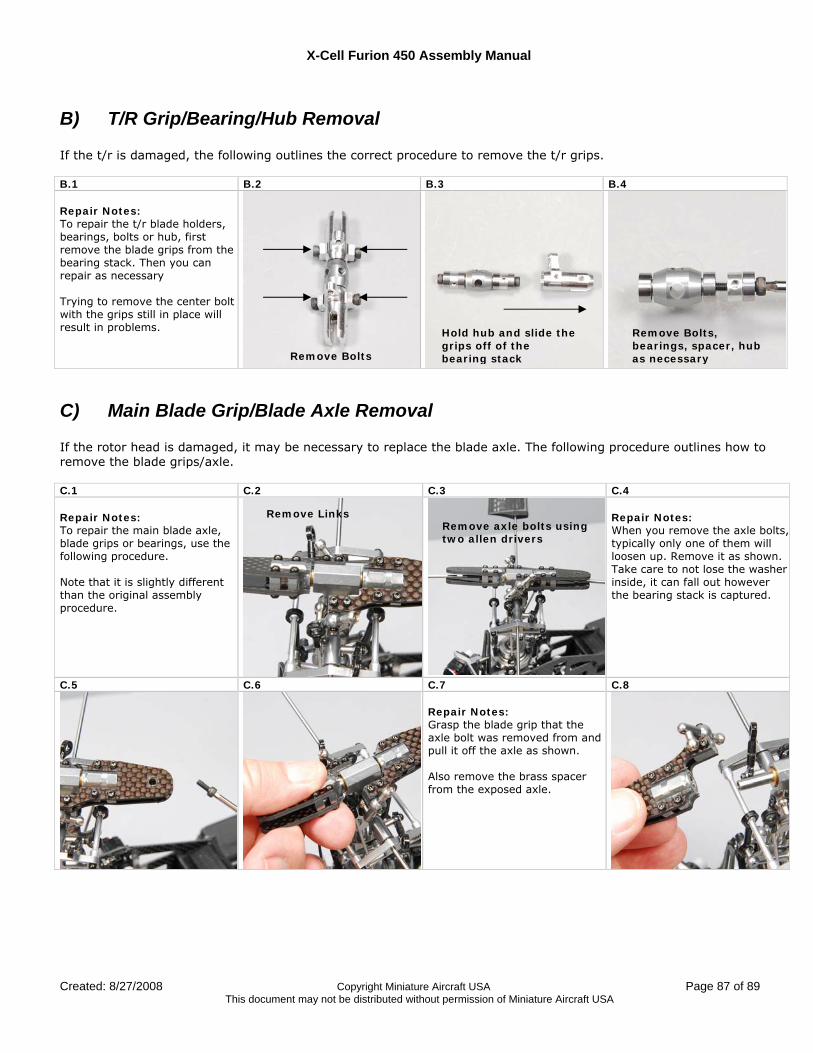
X-Cell Furion 450 Assembly Manual
Created: 8/27/2008 Copyright Miniature Aircraft USA Page 87 of 89 This document may not be distributed without permission of Miniature Aircraft USA
B) T/R Grip/Bearing/Hub Removal If the t/r is damaged, the following outlines the correct procedure to remove the t/r grips. B.1 B.2 B.3 B.4 Repair Notes: To repair the t/r blade holders, bearings, bolts or hub, first remove the blade grips from the bearing stack. Then you can repair as necessary Trying to remove the center bolt with the grips still in place will result in problems.
C) Main Blade Grip/Blade Axle Removal If the rotor head is damaged, it may be necessary to replace the blade axle. The following procedure outlines how to remove the blade grips/axle. C.1 C.2 C.3 C.4 Repair Notes: To repair the main blade axle, blade grips or bearings, use the following procedure. Note that it is slightly different than the original assembly procedure.
Repair Notes: When you remove the axle bolts, typically only one of them will loosen up. Remove it as shown. Take care to not lose the washer inside, it can fall out however the bearing stack is captured.
C.5 C.6 C.7 C.8
Repair Notes: Grasp the blade grip that the axle bolt was removed from and pull it off the axle as shown. Also remove the brass spacer from the exposed axle.
Remove Bolts
Hold hub and slide the grips off of the bearing stack
Remove Bolts, bearings, spacer, hub as necessary
Remove Links Remove axle bolts using two allen drivers
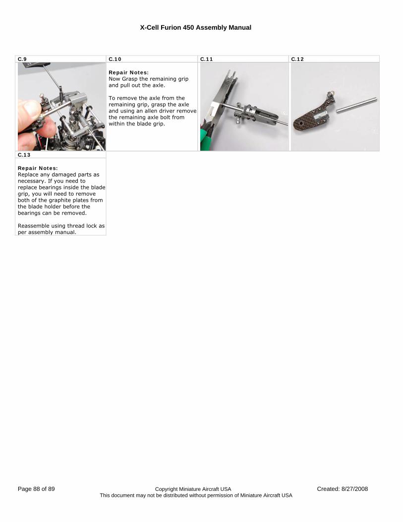
X-Cell Furion 450 Assembly Manual
Page 88 of 89 Copyright Miniature Aircraft USA Created: 8/27/2008 This document may not be distributed without permission of Miniature Aircraft USA
C.9 C.10 C.11 C.12
Repair Notes: Now Grasp the remaining grip and pull out the axle. To remove the axle from the remaining grip, grasp the axle and using an allen driver remove the remaining axle bolt from within the blade grip.
C.13 Repair Notes: Replace any damaged parts as necessary. If you need to replace bearings inside the blade grip, you will need to remove both of the graphite plates from the blade holder before the bearings can be removed. Reassemble using thread lock as per assembly manual.

X-Cell Furion 450 Assembly Manual
Created: 8/27/2008 Copyright Miniature Aircraft USA Page 89 of 89 This document may not be distributed without permission of Miniature Aircraft USA