WP2.5.1 Correlator and Central Beamformer€¦ok, or join forces/collaborate on recommendations. –...
44
1 WP2.5.1 Correlator and Central Beamformer B. Carlson
Transcript of WP2.5.1 Correlator and Central Beamformer€¦ok, or join forces/collaborate on recommendations. –...

1
WP2.5.1Correlator and Central Beamformer
B. Carlson

2
Overview• Contributors.• Requirements, challenges.• Task Plan.• CoDR documents, timeline, and requirements.• Institute status
– S/W correlator.– JIVE + Astron.– MeerKAT/CASPER.– SKADS.– CSIRO.– NRC/DRAO.

3
Contributors• S/W Correlator
– Jongsoo Kim• JIVE+Astron
– Arpad Szomoru• MeerKAT/CASPER
– Francois Kapp, SA• SKADS
– Andy Faulkner• CSIRO/ICT
– John Bunton• NRC/DRAO
– Brent Carlson

4
Requirements1 & Challenges• SAA
– 250 antennas, 0.4 GHz/pp, 1200 beams/pp, ~100k chan/basl• DAA
– 250 antennas, 0.6 GHz/pp, 1200 beams/pp, ~100k chan/basl• PAFs
– ~2000 antennas, 0.6 GHz/pp, ~30 beams/pp, ~100k chan/basl• WBSPFs
– ~3000 antennas, ~9 GHz/pp, 1 beam, ~100k chan/basl.• Tied-array/central beamformer output
– Ideally, enough beams to fill in each “antenna” beam…but practically limited by compute cost/architecture…and hardware to do something with it!
1 SKA memo 126, Table 1, Bunton

5
• Flexibilities?– Common arch? Configurable tradeoffs of various parameters if
“all” not possible?– (Reasonably) rapid technology upgrades?
• Reliability/interoperability.– Requires stepped-up rigour in all aspects of the design life cycle
due to high volume, remote locations.– Develop/adhere to standards; standards testing, margin testing.
Will pay dividends in interoperability/system integration and test. – Reliability requirements; reliability analysis and testing.
Production model accelerated life testing(?)

6
Task Plan
• WP2.5.1.• SPDO support (DS: Wallace Turner):
– Organization/direction.– Doc standards, dissemination of information.– Requirements, direction.– Standards organization(?)– Timelines and milestones (schedule, DRs, DR requirements).– Organized, evidence-based decision making via review
committees.– Feedback/consultation.

7
• Internationally diverse set of DSP/digital electronics engineers with:– Different experiences.– Different methodologies.– Different motivations.– Different limitations/resources.– Different ideas.
• Many bright individuals with lots of different ideas.– Don’t think it will be possible to “all get together” and decide now
on how to build the correlator(s).• Don’t limit/constrain thinking; but provide framework and
timelines for decision making and vetting of proposals.– Set common and fair standards of evaluation.– Foster spirit of intellectual buy-in into final chosen
architecture(s)…many small groups…a lot of work to do!

8
CoDR
• SPDO documentation:– 01-WP2-040.030.010-TD-001-B_HighLevelDescr.docx– 07-WP2-040.030.000.SRS-001-B_SKASPReqSpec.pdf– 02-WP2-040.030.011.TD-001-A_SKATechnologyRoadmap.pdf– Requirements for CoDR (?) + spreadsheet.
• CoDR:– ~spring of 2011.– External review committee.– Invite all interested institutes to present proposals; reqs for CoDR
doc defines requirements, what is required, how evaluation is performed.
9
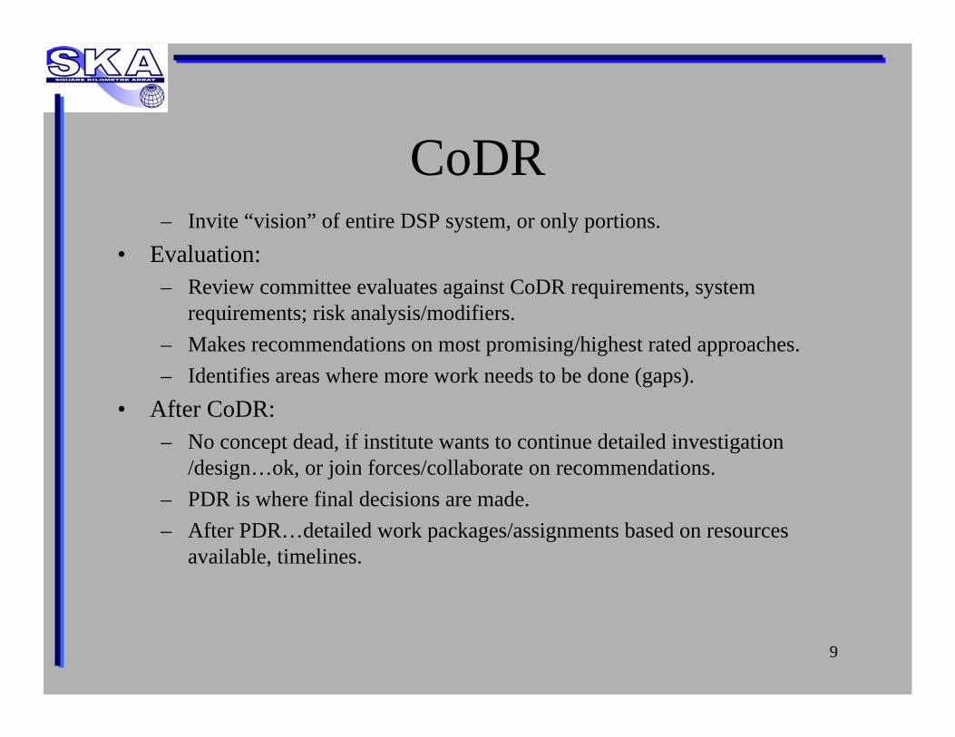
CoDR– Invite “vision” of entire DSP system, or only portions.
• Evaluation:– Review committee evaluates against CoDR requirements, system
requirements; risk analysis/modifiers.– Makes recommendations on most promising/highest rated approaches.– Identifies areas where more work needs to be done (gaps).
• After CoDR:– No concept dead, if institute wants to continue detailed investigation
/design…ok, or join forces/collaborate on recommendations.– PDR is where final decisions are made.– After PDR…detailed work packages/assignments based on resources
available, timelines.

10
S/W Correlator
Jongsoo Kim

11
• We designed a software correlator for SKA1 Mid (dishes)
• Assumed specifications (Memo 125)– 250 15m antennas– 4GHz bandwidth– 4 bits sampling
• Used technologies– 100 Gigabit Ethernet– many-core processing units (CPUs/GPUs)– high-performance interconnect (infiniband)
Software Correlator for SKA1 Mid (dishes)

12
CPUs+(GPUs)
CPUs+(GPUs)
CPUs+(GPUs)
CPUs+(GPUs)
CPUs+(GPUs)
CPUs+(GPUs)
InfinibandOr
Other options
100 Gb/s Ethernet
Software Correlator for SKA1
1x4x2x4GHz =32Gb/s1 pols, 4bit sampling, Nyquist, BW
500 nodes
>8 TFLOPS
CPUs+(GPUs)1x4x2x4GHz =32Gb/s
CPUs+(GPUs)
>4 PFLOPS

13
Milestones
• Design of a software correlator for the SKA1sparse aperture array
• Do benchmark tests of FX correlation using currently available high-performance many-core clusters
• Write a SKA memo on software correlators for the SKA1
• Look at technology options of a software correlator for the SKA2 sparse aperture array

14
JIVE + Astron
Arpad Szomoru (JIVE)

15
The UniBoard • A RadioNet FP7 Joint Research Activity, 9
partners• Multi-purpose, scalable, high performance, generic
interfaces (10GE, DDR3)• Per board: 8 Altera Stratix IV FPGAs (40 nm), 2 × 16
× 10 Gbps, each front node to all back node mesh (more info: see poster)
• JIVE: project lead, ASTRON: hardware development
• KASI, INAF, ShAO, Universities of Bordeaux, Orléans, Manchester, Oxford: various applications
• Prototype undergoing tests now
• Currently under development: VLBI correlator (JIVE), digital receiver (INAF, BORD), pulsar binning machine + RFI mitigation (UMAN, UORL)
• Coming soon: APERTIF correlator + beam former (ASTRON), all-station LOFAR correlator (ASTRON + University of Amsterdam, Oxford), more applications on the way
QuickTime™ and a decompressor
are needed to see this picture.
QuickTime™ and a decompressor
are needed to see this picture.
Contract no. 227290

16
SKA-like configurations
• Corner turning done in network
• 256 telescope correlator, 1GHz, 2 pol, 8 bits
• Could be built now using existing hardware (infinibandswitches)
• 320 UniBoards, 16 switches
• Future scalability depends on capacity of future switches

17
SKA-like configurations (2)• Combination of UniBoards into
larger systems via backplane
• Will be developed through NWO-funded ExBox project (JIVE-ASTRON collaboration)
• Application in APERTIF (ASTRON)– Correlator for 12 dual pol dishes,
300 MHz bandwidth, 37 beams– 32 UniBoards
• Application in AARTFAAC (University of Amsterdam-ASTRON collaboration)
– Correlator for 576 signal paths, ~ 17.5 MHz bandwidth
– 12 UniBoards
24*2*4
X-subbands
BF-subbands
backplane
24*2*2
All beams with each 24 dual pol BF-subbands from 12 telescopes
24*2*12
Empty slot
Full Stokes visibilities of 24 BF-subbands bandwidth and for all beamsto the post processing via 1 GbE control links
UniBoard
Back nodeFront node
Correlator
Filterbank
transpose
4
8
24
APERTIF correlator

18
Next: UniBoard2
• Possible Joint Research Activity in RadioNet3, follow-up of current project, start date 2012 (if approved by EC...)
• Received strong support from RadioNet community• Same basic idea, development of generic hardware complemented by a number of
applications• Consolidate and build on expertise obtained through UniBoard project• Strong emphasis on power efficiency (green computing)• Production-ready in 2015/2016
• Complete re-design, using the next generation 28 nm FPGAs, possibly one generation beyond that (some slack in start date of project)
• Non-leaded components• Possible use of 40GE, 100GE• Investigation into effects of hard-copy and partial hard-copy• Tuning of algorithms and firmware design to minimize power consumption• Balancing of system parameters and performance to minimize power
consumption• Standardized interfaces and coding conventions to facilitate sharing and re-use of
firmware blocks among developers of different applications

19
• End of 2010, a well-documented power-consumption budget for the UniBoard
• Mid-2011 (after implementation of correlation and digital receiver design) , a report on the suitability of the specific FPGAs we have chosen (size, number of DSPs, amount of logic) and implications for a SKA implementation
• Report on the computing demands posed by different configurations and implications for hardware platform (length of baseline, frequency, number of bits, field of view vs. frequency smearing, bandwidth smearing)

20
MeerKAT/CASPER
Francois Kapp
21
• XDM, 15m dish – handed over to HartRAOfor Science use.
• Fringe Finder running since Q4 2009 –Commissioning of KAT-7 dishes.
• KAT-7 Correlator to be installed on-site Q4 2010 – Interferometric Commissioning, then Science/Engineering Test
• MeerKAT Requirements Analysis has started. Science proposals being distilled into Engineering Requirements.
SA Status and Direction

22
KAT-7 Aerial View

23
MeerKAT• What we do “know” for phase 1:
– Sampling close to/at feed (no RF over Fibre, but sampling clock to be distributed)
– L-band direct sampling– 64 Antenna system– “DFX” architecture with multiple
simultaneous modes– Planned future upgrades– Many TBD's...

24
CASPER and SKA?• CASKAR ;-)
– How much can SKA benefit from the flexibility and inherent scalability?
– How far does CASPER scale?– Can the roll-out of SKA be synchronised
with a continuous upgrade of the back end processing?
– Proposed road map to SKA

25
The Road to CASKAR

26
SKADS
Andy Faulkner

27
Requirements: SKA1 SKA2
No. of Stations 50 250Data rate/stn, Tb/s ~5? 16Correlator/b’former
“Shape” vs. dishes.. Few stations.. High Data Rate.. Extremely modular
... AA slice
... AA slice... AA slice
...D
ish & AA+D
ishC
orrelation
......
Data sw
itch
AA
Stations
Dishes
Correlator/Beamformer
Beams Visibilities/Beams
250 x 16Tb/s~4.8 Pb/s
2400 x 80Gb/s~200Tb/s
Tb/sPb/s
...
...
..........
To cluster processors: UV
or de-dis[pertion+spectralseparation
Consider an AA “slice”:.. 8 Gb/s/station ≈ 2x500MHz beams
.. 250 stns, 4-bit samples => 63T CMACs
.. Core b’former for 3deg2 ~1T CMAC/slice
.. Use e.g. 15 x 20TMAC chips
.. Build on one board
AA Correlator & AA Correlator & BeamformerBeamformer

28
Implementation......Implementation......Optical beam inputs
16 cards each: 16inputs of 8x10Gb/s8 AA slices
8 cards each: 256 inputs of 10Gb/s
........
........
256 Fibres.. 1 per station.. 16 per card.. 8 x 10Gb/s ea
Optical 1:8 demux Optical Rx Midplane
AA Slices: Correlator/Beamformer
Data Rx & “corner turner”
Shelf of 8 AA SlicesShelf of 8 AA Slices
Beams
Visibilities/
Timeseries

29
SKASKA2 2 AA AA Correlator/Correlator/BeamformerBeamformer
SKA2 Requires 16Tb/s:
.. Each Slice: 8 Gb/s
.. Each Shelf: 64 Gb/s⇒ 256 Shelves
3 Shelves per rack⇒ 80 Racks for SKA2
Processing device spec :
.. 20 TMAC processing
.. Programmable
.. 128 x 10 Gb/s i/p
.. 128 x 10 Gb/s o/p
.. 25-40 watt power reqt.
An AA Correlator/Beamformer
with ~5Pb/s data input is entirely
Feasible

30
CSIRO
John Bunton

31
ASKAP Requirements and technology
• ASKAP is a pathfinder for Dish with PAF technology• Each antenna generates 36 beam with a BW 0.3GHz
– Total BW processed 36 beams x 2 Pol x 0.3GHz = 21.6GHz– About half of bandwidth required for SKA
• 36 antennas ~1% SKA• Also building CABB, SKAMP and MWA correlators
• Technology Based on– FPGAs flexibility to explore options – fast prototyping– Time reordering of data to correlator. Process part of data at one time,
For ASKAP• 1 dual pol beam and 1MHz BW at any one time• Reduces memory requirements in correlator FPGA
– Full cross connect routing of data• Two data routing stages in correlator – low data transfer cost• Each FPGA does all baselines for limited bandwidth data

32
Redback DSP boards• ASKAP correlator uses Redback-2
processing boards• Based on industry standard
AdvancedTCA shelf with fully cross connected back plane
• 12 10G inputs to RTM• To Crosspoint Switch to backplane
– Data from single 4 port digitiser distributed to 16 Redback2 –19MHz each
• 4 LX240T processing FPGAs per board. • Separate smaller FPGA for command
and control (no microcontroller/DSP)• 8 x10G and dual 1GE ports for output
RTM Redback-2
AdvancedTCAshelf with full cross connect backplane

33
ASKAP Correlator
Correlator shelf (1 of 16)
• 36 beamformer– 16 Redback-2 each
• Corresponding board to 1 of 16 correlator shelf– 4 x 10 Gb/s– Decoded to 14 x 3Gb/s
• Distributed by ATCA back plane to 14 Redback-2 correlator boards
• Received by single FPGA on board. – Redistibuted by LVDS amongst
4 processing FPGA• All correlation for a given
frequency band in a single FPGA• 36 Tied array beams in same FPGA
Board N
Board N
Four x 10G
14 x 3G1.357MHz each
1 of 36 sets
Beamformers
Board N
0.34MHz processed in each FPGA
Cross point switch and backplane

34
SKA Data Flow• Data flow in the SKA correlator is a major
problem.• 100s of Gb/s per antenna• Tens of fibres per antenna fibres per antennas using
10G technology• SKA 50,000 fibres in 10G technology
– Need 100GE technology to reduce fibre number to reasonable value.
– Probably available for Phase 2• SKA memo 126 describes possible correlator
data flow.• For WBSPF and PAF Separate cross connection
system needed between correlator and antenna
This is what data for one antenna looks like currently
Rear of ASKAP beamformer

35
SKAMP/MWA Correlator Cell• SKAMP/MWA use a efficient 4-bit correlator cell
– One 18-bit multiplier and one 18kbit RAM– Processes 256 correlation for 1MHz bandwidth
• L. De Souza et al, ‘A Radioastronomy Correlator Optimised for the Virtex-4 SX FPGA’, IEEE FPL 2007, Amsterdam Aug 27-29,
– With 2012 FPGA – 4000 cells or 1,000,000 correlations at one time– In 2020 expect 16 times as much – 16M correlation for 1.5MHz
• 4M baselines full stokes – equivalent to 2830 antennas• Single large FPGA close to handling all antennas for 1.5MHz
– Or two midrange FPGAs for 3000 inputs– Input data rate 3000 antennas x 2 pol x1.5MS/s x 4+4bit = 72Gb/s
• 2012 FPGAs can handle 66Gb/s– 1300 FPGAs per GHz of bandwidth
• 8 per board and 16 boards per shelf = 10 shelves/GHz = 4-5 cabinets

36
NRC/DRAO
Brent Carlson
National Research CouncilCanada
Conseil national de recherchesCanada

37
Current Status/Dev.
• EVLA correlator—nearly complete:– Production complete, all boards shipped, installed; observing now.– Warranty, documentation, handover, troubleshooting + support as
needed.
• Multi-purpose FPGA Board (Ljusic, Zhang)– ATCA form factor.– 8 Virtex-6 FPGAs.– Use for APHAD, adaptive optics, possible industry collaboration
for BSP, other SKA DSP processing testing.– Currently in detailed layout…1st prototype ~Q1 2011.

38

39
Giant Systolic Array (GSA)• SKA Memo 127 sets baseline design concept. Poly-phase FX.• Looking forward to full scale SKA correlator…in a concrete way that is
realizable using just emerging technologies (10G/diff pair).• Distributed partial corner turner in the F-part—no monolithic corner turner.
– 1 10G stream contains ~ 8 ants, 50 MHz/pp, ~1000 channels. Numbers subject to change.
– Single insertion point-to-point F to X part (fiber).• Nearest-neighbour 10G connections between chips and
boards…fundamentally highest bandwidth, lowest cost.– No cable within X part…nearest neighbour board-to-board connections
established with “printed wiring” connections.– Tied array conveniently formed from row outputs in X part.
• Conducive to staged SKA deployment, technology upgrades without replacing system infrastructure.

40
16384baseline100 MHz
corr
Antenna Inputs
10G RX 10G RX
10G TX 10G TX
256 baseline100 MHz
4-bit correlator
8 ants
8 ants
8 ants8 ants
128 ants
Repeaters
128 ants
Repeaters
GSA Concept
23
23
23
Example: 2944 antennas50 MHz/pol’n; 4-bits complex4096 chans/baseline1 beam4.3 M-baseline correlator
23x24/2=276 GSA cards
Pizza Box (16384 baselines, 100 MHz correlator)
10% SKA

41
Inputs from F-part
Inputs from F-partB
and
1
Ban
d 2

42
~6.9
m
~13
m
2944
ant
enna
s, 1
GH
z/po
l’n, 1
bea
m c
orre
lato
r
10%
SK
A(3
84 a
nten
nas)
43
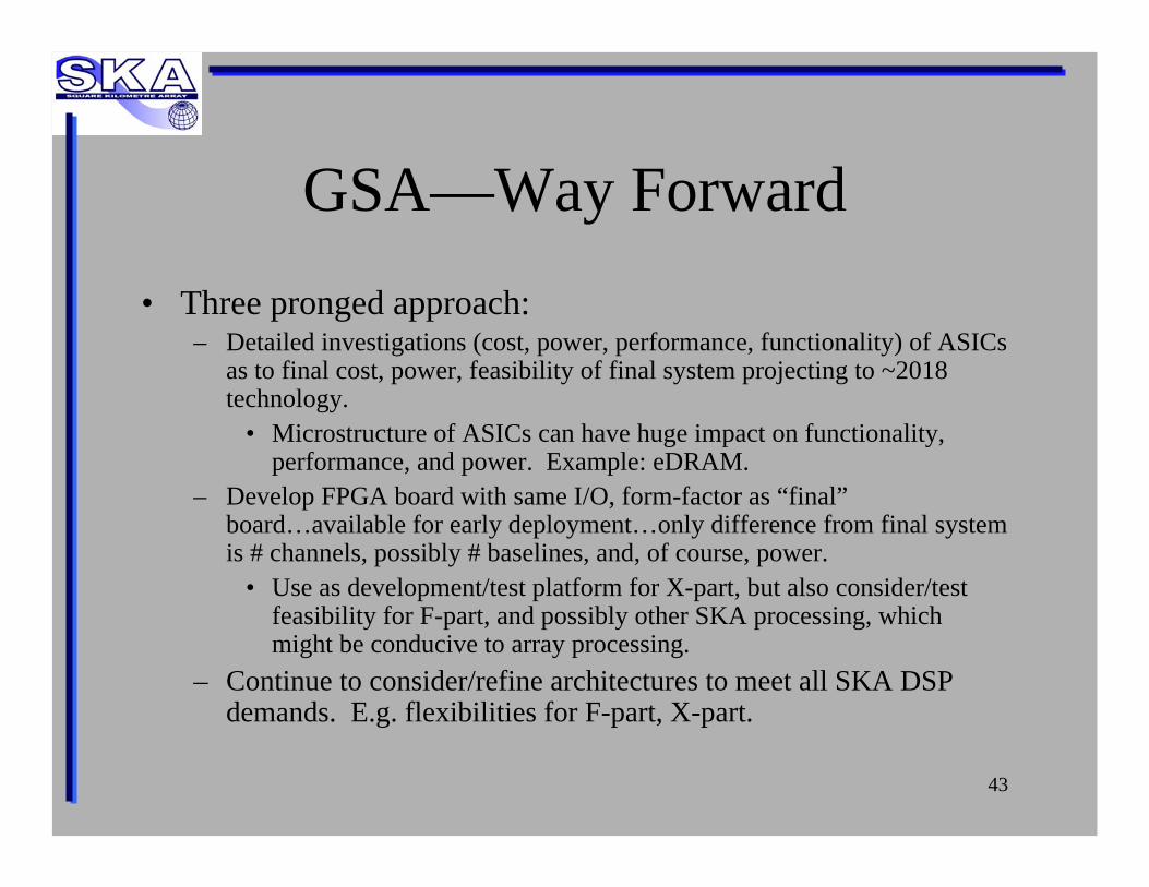
GSA—Way Forward• Three pronged approach:
– Detailed investigations (cost, power, performance, functionality) of ASICsas to final cost, power, feasibility of final system projecting to ~2018 technology.
• Microstructure of ASICs can have huge impact on functionality, performance, and power. Example: eDRAM.
– Develop FPGA board with same I/O, form-factor as “final”board…available for early deployment…only difference from final system is # channels, possibly # baselines, and, of course, power.
• Use as development/test platform for X-part, but also consider/test feasibility for F-part, and possibly other SKA processing, which might be conducive to array processing.
– Continue to consider/refine architectures to meet all SKA DSP demands. E.g. flexibilities for F-part, X-part.

44
Summary• Contributors.• Requirements, challenges.• Task Plan.• CoDR documents, timeline, and requirements.• Institute status
– S/W correlator.– JIVE + ASTRON.– MeerKAT/CASPER.– SKADS.– CSIRO.– NRC/DRAO.