Cobalt: A GPU-based correlator and beamformer for LOFAR · Cobalt: A GPU-based correlator and...
15
Cobalt: A GPU-based correlator and beamformer for LOFAR P. Chris Broekema *1 , J. Jan David Mol 1 , Ronald Nijboer 1 , Alexander S. van Amesfoort 1 , Michiel A. Brentjens 1 , G. Marcel Loose 1 , Wouter F. A. Klijn 1 , and John W. Romein 1 1 ASTRON, the Netherlands Institute for Radio Astronomy, Postbus 2, 7990 AA, Dwingeloo, the Netherlands Abstract For low-frequency radio astronomy, software correlation and beamforming on general purpose hardware is a viable al- ternative to custom designed hardware. LOFAR, a new- generation radio telescope centered in the Netherlands with international stations in Germany, France, Ireland, Poland, Sweden and the UK, has successfully used software real-time processors based on IBM Blue Gene technology since 2004. Since then, developments in technology have allowed us to build a system based on commercial off-the-shelf compo- nents that combines the same capabilities with lower oper- ational cost. In this paper we describe the design and imple- mentation of a GPU-based correlator and beamformer with the same capabilities as the Blue Gene based systems. We focus on the design approach taken, and show the challenges faced in selecting an appropriate system. The design, im- plementation and verification of the software system shows the value of a modern test-driven development approach. Operational experience, based on three years of operations, demonstrates that a general purpose system is a good al- ternative to the previous supercomputer-based system or custom-designed hardware. 1 Introduction The LOw Frequency ARray (LOFAR) [1] radio telescope is often described as one of the first of a new generation of software telescopes. LOFAR has pioneered the use of a com- bined software correlator and beamformer in an operational radio telescope since 2004 [2, 3, 4]. One key characteristic of a software telescope is the ability to ride the technology wave to increase functionality and/or reduce operational cost by leveraging new developments. In this paper we dis- cuss the hardware design of the third generation Graph- ics Processing Unit (GPU) based LOFAR software correla- tor and beamformer: Cobalt (COrrelator and Beamformer Application for the LOFAR Telescope), as well as the de- sign and development of the associated software. Since the tasks of this real-time central processor are * Corresponding author: [email protected] well known and clearly defined, this application is an ex- cellent candidate for a focused hardware/software co-design approach. In this paper we describe the following concepts that in combination led to the success of Cobalt: • A data flow-driven design philosophy; • Hardware/software co-design; • Data flow analysis and task mapping to identify po- tential weaknesses in available HPC solutions for our streaming application; • Close public-private collaboration in the hardware de- sign, which showed the clear advantages of such a part- nership in this kind of project; • A simplified system engineering approach in the design and implementation phases of the project; • An agile software engineering methodology to ensure timely delivery within budget; • A Test-driven software development process to improve the robustness of our system. 2 Related work The Cobalt project built on previous experience with com- bined software correlator and beamformer systems in the LOFAR telescope [2, 3, 4]. We discuss some aspects of these in more detail in Section 3.1. Cobalt shared common ancestry with the AARTFAAC correlator [5], although the radically different I/O ratio led to different design decisions. There are several other software correlators in use in radio astronomy. Here we briefly discuss some of these in relation to the Cobalt system. We limit ourselves to FX-correlators, that combine a filter- and Fourier transform (F) stage with a cross-correlation (X) stage The correlators used by the Murchison Widefield Array (MWA) [6], the Large Aperture Experiment to Detect the Dark Ages (LEDA) [7], and PAPER [8] all share the same general architecture. Whereas Cobalt implements both the filter (F-stage) and the correlator (X-stage) in GPUs, the above mentioned instruments employ a hybrid FPGA-GPU approach. The F-stage is implemented in FPGA, the X- 1 arXiv:1801.04834v3 [astro-ph.IM] 30 Apr 2018
Transcript of Cobalt: A GPU-based correlator and beamformer for LOFAR · Cobalt: A GPU-based correlator and...

Cobalt:
A GPU-based correlator and beamformer for LOFAR
P.Chris Broekema∗1, J. Jan David Mol1, Ronald Nijboer1, Alexander S. van Amesfoort1, Michiel A.Brentjens1, G.Marcel Loose1, Wouter F.A. Klijn1, and JohnW. Romein1
1ASTRON, the Netherlands Institute for Radio Astronomy, Postbus 2, 7990 AA, Dwingeloo, the Netherlands
Abstract
For low-frequency radio astronomy, software correlation andbeamforming on general purpose hardware is a viable al-ternative to custom designed hardware. LOFAR, a new-generation radio telescope centered in the Netherlands withinternational stations in Germany, France, Ireland, Poland,Sweden and the UK, has successfully used software real-timeprocessors based on IBM Blue Gene technology since 2004.Since then, developments in technology have allowed us tobuild a system based on commercial off-the-shelf compo-nents that combines the same capabilities with lower oper-ational cost. In this paper we describe the design and imple-mentation of a GPU-based correlator and beamformer withthe same capabilities as the Blue Gene based systems. Wefocus on the design approach taken, and show the challengesfaced in selecting an appropriate system. The design, im-plementation and verification of the software system showsthe value of a modern test-driven development approach.Operational experience, based on three years of operations,demonstrates that a general purpose system is a good al-ternative to the previous supercomputer-based system orcustom-designed hardware.
1 Introduction
The LOw Frequency ARray (LOFAR) [1] radio telescopeis often described as one of the first of a new generation ofsoftware telescopes. LOFAR has pioneered the use of a com-bined software correlator and beamformer in an operationalradio telescope since 2004 [2, 3, 4]. One key characteristicof a software telescope is the ability to ride the technologywave to increase functionality and/or reduce operationalcost by leveraging new developments. In this paper we dis-cuss the hardware design of the third generation Graph-ics Processing Unit (GPU) based LOFAR software correla-tor and beamformer: Cobalt (COrrelator and BeamformerApplication for the LOFAR Telescope), as well as the de-sign and development of the associated software.
Since the tasks of this real-time central processor are
∗Corresponding author: [email protected]
well known and clearly defined, this application is an ex-cellent candidate for a focused hardware/software co-designapproach.
In this paper we describe the following concepts that incombination led to the success of Cobalt:
• A data flow-driven design philosophy;
• Hardware/software co-design;
• Data flow analysis and task mapping to identify po-tential weaknesses in available HPC solutions for ourstreaming application;
• Close public-private collaboration in the hardware de-sign, which showed the clear advantages of such a part-nership in this kind of project;
• A simplified system engineering approach in the designand implementation phases of the project;
• An agile software engineering methodology to ensuretimely delivery within budget;
• A Test-driven software development process to improvethe robustness of our system.
2 Related work
The Cobalt project built on previous experience with com-bined software correlator and beamformer systems in theLOFAR telescope [2, 3, 4]. We discuss some aspects ofthese in more detail in Section 3.1. Cobalt shared commonancestry with the AARTFAAC correlator [5], although theradically different I/O ratio led to different design decisions.
There are several other software correlators in use in radioastronomy. Here we briefly discuss some of these in relationto the Cobalt system. We limit ourselves to FX-correlators,that combine a filter- and Fourier transform (F) stage witha cross-correlation (X) stage
The correlators used by the Murchison Widefield Array(MWA) [6], the Large Aperture Experiment to Detect theDark Ages (LEDA) [7], and PAPER [8] all share the samegeneral architecture. Whereas Cobalt implements both thefilter (F-stage) and the correlator (X-stage) in GPUs, theabove mentioned instruments employ a hybrid FPGA-GPUapproach. The F-stage is implemented in FPGA, the X-
1
arX
iv:1
801.
0483
4v3
[as
tro-
ph.I
M]
30
Apr
201
8

stage is implemented in GPUs using the xGPU library [9].A high bandwidth switch connects the F- and X-stages.
The Giant Metrewave Radio Telescope (GMRT) real-timesoftware backend [10] uses a structure similar to the MWAcorrelator, with nodes dedicated to three specific tasks. Inthis case the software backend relies on conventional CPUsonly, with heavy use of off-the-shelf performance optimizedlibraries.
For Very Long Baseline Interferometry (VLBI) a numberof software correlators have been developed. Examples ofthese are SFXC, developed by JIVE [11], and DiFX [12,13]. These perform tasks similar to Cobalt, although DiFXdoes not include a beamformer. However, data rates areusually modest compared to those generated by the LOFARstations.
A real-time software correlator has been developed anddeployed for the Canadian Hydrogen Intensity Mapping Ex-periment (CHIME) pathfinder [14]. The correlator stage ofthis system is very similar in concept and size to Cobalt,but implements the F-stage in FPGAs, requiring additionalcommunication from the F to the X stage. In Cobalt the Fand X stage use the same hardware.
3 LOFAR: the Low Frequency Ar-ray
LOFAR, the LOw Frequency ARay, is a new-generation ra-dio telescope, built in the northern part of the Netherlands,with international stations distributed across Europe. Asthe name suggests, it is designed to observe in the relativelylow and unexplored frequency range of 10 to 250 MHz. Thearray consists of 40 stations: 24 core and 16 remote, in theNetherlands, with an additional 13 international stations, 6in Germany, 3 in Poland and one each in France, Ireland,Sweden, and the UK.
Each station consists of two receiver types, low banddipole antennas and high band antenna tiles, covering ei-ther side of the commercial FM band. A LOFAR stationconsists of 96 Low Band Antennas (LBAs), operating from10 to 90 MHz. In addition, Dutch core stations have 48High Band Antenna (HBA) tiles in two clusters that coverthe frequency range from 110 to 250 MHz. Remote stationsin the Netherlands have the same number of HBA tiles, in asingle cluster. International stations provide a single clusterof 96 HBA tiles.
At each LOFAR station dedicated processing equipmentsamples, digitises and digitally filters data using a polyphasefilter bank. This filterbank produces 512 frequency bandswith a spectral bandwidth of 195 kHz. By coherently addingthe same frequency bands of individual antennas or tiles,station beams are created. Such a beamformed frequencyblock is referred to as a subband, 488 of which may be se-lected per observation, giving a total spectral bandwidth of95 MHz (in the most common 8-bit mode). Spectral band-width may be exchanged for beams, essentially allowing upto 488 independent (narrow-band) pointings to be made.Core stations may be split, allowing the two HBA clustersto be treated as smaller, but fully independent, stations.
To distinguish them from physical stations, these are calledantenna fields, 77 of which currently make up the LOFARarray. Subbands produced by these antenna fields are trans-ported to the central processing facility, hosted by the Uni-versity of Groningen, about 50 kilometers from the LOFARcore area, using UDP/IP over many 10 Gigabit Ethernetlinks.
The central processor can be divided into three distinctcomponents: the real-time processor, the post-processingcluster, and the archive. The real-time processor (Cobalt),which implements a correlator and beamformer, is a softreal-time system that collects data from the antenna fields,conditions this data, applies a second polyphase filter,and subsequently combines all antenna fields (beamformermode) or all antenna field pairs (correlator mode) to pro-duce intermediate results. Although there is no hard dead-line in the sub-second range as in a classic real-time system,it is required that the central processor keeps up with theantenna field data streams, otherwise data is irretrievablylost. In Section 3.2 we discuss the processing steps thatmake up the real-time system.
Output from the real-time processor is stored on the post-processing cluster. This is a conventional Linux cluster,with significant disk capacity to store intermediate prod-ucts and facilitate further processing. Here, instrument cal-ibration is performed, possible interference is identified andremoved, and final products (images, pulse profiles, sourcelists) are created.
Final products are exported to the LOFAR long-termarchive, which is currently distributed over three sites: Am-sterdam hosted by SURFsara in the Netherlands, Julichhosted by Forschungszentrum Julich in Germany, and Poz-nan hosted by PSNC in Poland. Astronomers retrieve theirdata from one of these archive sites, no end-user interac-tion with the LOFAR system is required. Figure 1 shows atop-level overview of the LOFAR system.
The remainder of this paper will focus on the LOFARreal-time processor.
3.1 The LOFAR real-time processor
The LOFAR project decided early on to employ generalpurpose computing for the real-time processor, both to ex-ploit the fact continued developments in general purposeprocessor technology had made this feasible, and to saveprecious FPGA development resources for the station pro-cessing boards. Initially, the requirements for the LOFARreal-time processor were quite challenging for a general pur-pose compute system. The only feasible option availablewas to use a supercomputer. In 2004, an IBM Blue Gene/Lwas installed at the LOFAR central processor. At the time,the LOFAR real-time processor was the fastest supercom-puter in the Netherlands, and the second fastest in Europe1.Although compute performance of the Blue Gene/L was suf-ficient, significant research and development was required toachieve the required I/O performance [2, 15].
In 2008 the six rack Blue Gene/L system was upgradedto a slightly more powerful, but much smaller and more
1https://www.top500.org/lists/2005/06/
2

Figure 1: Top-level overview of the LOFAR system.
energy-efficient three rack Blue Gene/P system. While asignificant improvement over its predecessor in terms of pro-gramming environment and general hardware features, con-siderable research was again required to achieve the I/Operformance required [16, 17, 18].
While the Blue Gene real-time processors were opera-tional, research continued into various other software alter-natives [3, 19]. The advent of many-core architectures forhigh performance computing, in particular Graphics Pro-cessing Units (GPUs), allowed us to move away from su-percomputers, and instead build the third-generation cor-relator and beamformer based on general-purpose serverhardware and accelerators. In this paper we discuss thedesign approach taken, we show some of the problems en-countered and how these were tackled, and we concludewith the successful commissioning into operational serviceof a new, GPU-based, LOFAR correlator and beamformer.Several years of operational statistics are presented in Sec-tion 9.
3.2 Processing steps
The LOFAR real-time processor receives data from LOFARantenna fields as continuous UDP/IP data streams. Missingand out-of-order packets are identified and, where possible,corrected. Data that has not arrived after a short deadlineis considered lost. Each incoming data stream contains allfrequency data from a single antenna field, while each pro-cessing node for a given frequency range requires data fromall antenna fields. Therefore, a transpose is required on theincoming data, before further processing.
The processing component is complex and involves anumber of optional sub-components, as shown in Figure2. Data is converted from fixed to floating point to bet-ter match the hardware available in a general purpose com-puter. The current LOFAR real-time processor uses singleprecision complex floating point throughout, with one ex-ception: calculating delays for delay compensation. Twomain pipelines are implemented that can run in parallel.The correlator pipeline implements an FX-style correlator,the components of which were described in more detail inearlier work [3]. The beamformer pipeline consist of co-herent and incoherent components, as well as a complexvoltage pipeline, details of which were previously publishedas well [4]. In Section 7.5 we describe how these processingsteps are implemented in Cobalt.
4 Development process
The relatively modest scale of the project allowed us to usea slightly simplified system engineering approach in the de-sign of this system. First, the system requirements, bothfunctional and non-functional, were identified (see Section5). From these, a high-level architecture was derived (Sec-tion 6). This, combined with a detailed analysis of the var-ious aspects of the application performance profile, such asnetwork data flow (Section 6.3), memory footprint (Sec-tion 6.3.1) and computational load (Section 6.1 and Sec-tion 6.3.2) led to a detailed design of the system hard-ware (Section 6.5). During the hardware implementationphase, a single prototype node was used to verify that theselected hardware implementation met the performance re-quirements (Section 6.4). Finally, the fully deployed systemwas verified against the system requirements (Section 8).This process closely mirrors a traditional systems engineer-ing approach, but the relatively small project size meant wecould simplify the process by eliminating most of the formaldocumentation.
Before the start of the Cobalt project the feasibility ofa GPU-based solution was researched and optimized GPUkernels had been developed. Moreover, a highly optimizedand proven Blue Gene implementation of all required func-tionality was available. However, a different hardware archi-tecture and steep performance, maintenance and reliabilityrequirements, necessitated redesign of our on-line process-ing software, except for wrapper and support libraries. Thebeamformer pipeline was redesigned, so several GPU ker-nels had to be adapted or rewritten.
The development process was paramount to obtain cor-rect output and adequate performance within a limitedtime frame. We used the Agile/Scrum development pro-cess [20, 21] to focus a small software team on a commongoal, divide and plan remaining work, and periodically triedto improve our practices.
5 System requirements
The following hard and soft requirements were put on theCobalt system. In terms of functional requirements, theCobalt system must :
• be able to correlate 64 antenna fields in 16 bit modeand in 8 bit mode at full bandwidth (for a single beam),i.e. with 244 resp. 488 subbands, down to 1 sec timeresolution and at maximum 256 channels per subband
3

Int to FloatFine Delay
Compensation
Transposed antenna field data in CPU memory Correlated subband data and beam data in CPU memory
FFT 64-512FIR 16BandpassCorrection
CorrelationTime
Averagingto 0.25-1 s
Correlator Pipeline
Int to Float FFT 256Fine Delay
CompensationBandpassCorrection
CoherentBeamforming1-222 beams
IFFT 256FIR 16
(optional)FFT 16-64(optional)
ComputeStokes
I or IQUV(optional)
TimeAveragingby 2-8x
(optional)
IFFT 256FIR 16
(optional)FFT 16-64(optional)
ComputeStokes
I or IQUV
TimeAveragingby 2-8x
(optional)
Sum overAntenna Fields
(1 beam)
Beamformer Pipeline
T
TT T
S
S
ST
T
T
T or SData reorder (Transpose or(FFT) Shift) in a GPU kernel
Two pipeline steps and a datatranspose in one GPU kernel
Coherent Stokes orComplex Voltages
IncoherentStokes
Figure 2: Signal processing steps in the correlator and beamformer pipelines.
frequency resolution. In this mode up to 8 indepen-dent beams can be made, in which case the numberof beams, the total bandwidth and the number of bitshave to be traded against each other.
• be able to create 127 time domain data streams usingall 48 core antenna fields in 16-bit mode at full band-width. These can be recorded in one of three modes:1) coherent addition (Stokes I only or Stokes IQUV,referred to as a coherent tied-array beam), 2) incoher-ent addition (Stokes I only or Stokes IQUV, referredto as an incoherent tied-array beam), or 3) coherentcomplex voltage (XX, XY, YX, YY). Time resolutioncan be traded against frequency resolution, within theresolution of a subband.
In addition, there were the following non-functional require-ments. The system must be delivered in time and withinbudget. It must have hardware, software, and data in-put/output connections installed, tested, and debugged in astaged approach. The system must have a design that allowsto scale up and be prepared for future planned modes andfunctionality. Furthermore, the system must have an op-erational availability greater than 95% (excluding plannedservice), while having a system maintenance staff effort ofless than 0.25 FTE, delivered during business hours only.The total operating costs per year must be lower than 50%of the (one-time) capital investment costs.
The non-functional requirements on Scalability, Opera-tional Availability (i.e. robustness) and Maintenance Ef-fort (i.e. maintainability) translated into software quality,programming environment, software support, test environ-ment, non-monolithic design, etc.
In addition to the hard requirements there were the fol-lowing soft requirements, i.e. nice-to-haves. The Cobalt sys-tem should be able to handle more LOFAR data, such as e.g.doing parallel LBA and HBA observing (doubling the num-ber of available subbands, and doubles the required Cobalt
capacity for a given observation), correlating more antennafields (up to 80), correlating longer baselines (up to 3500km), creating more beams (up to 200), or operating in 4-bitmode (which would double the number of available sub-bands, at the cost of some dynamic range, again doublingrequired Cobalt capacity for a given observation).
It should have the capacity to handle additional onlinetasks, e.g. Fly’s-eye mode in which we store antenna fielddata without central beamforming, handling of more than8 independent beams in correlator mode, online flagging,and beamforming the six central stations (”superterp”) be-fore correlation. Cobalt should also have the capacity tohandle additional offline processing tasks including auto-matic flagging, (self-) calibration and averaging, coherentde-dispersion of pulsar data and production of dynamicspectra and additional parts of the pulsar pipeline: onlinefolding and online searching.
Finally, Cobalt should prepare for future extensions, suchas commensal observing, parallel observing with sub-arrays,responsiveness to triggers and interrupts, and additional ob-serving modes.
6 Hardware design and implemen-tation
In the design process we focused on data flow rather thancompute requirements. One of the key characteristics of theLOFAR real-time processor is a relatively high data rate.While making sufficient compute capacity available was akey requirement, efficient use of this capacity critically de-pends on efficient data flow through the system. Further-more, previous many-core correlator research meant thatthe computational requirements and challenges were rela-tively well understood. We therefore made the conscious, ifsomewhat counter-intuitive, decision to focus our hardwaredesign for the Cobalt system on data flow, with computa-
4

Component Requirement Design target
Input bandwidth ∼192 Gbps (64 antenna fields) ∼240 Gbps (80 antenna fields)Output bandwidth 80 Gbps ≥80 GbpsInterconnect input + output bandwidth >2 * (input + output bandwidth)Correlator 64 antenna fields, 244 (16-bit) - 488 (8-bit) subbands 80 antenna fields, 244 (16-bit) - 488 (8-bit) subbandsBeamformer 127 beams, 48 antenna fields, 244 (16-bit) subbands 200 beams, 48 antenna fields, 244 (16-bit) subbands
Table 1: Top-level hardware requirements for Cobalt
tional capacity a crucial but secondary design goal.
6.1 Hardware requirements and design pri-orities
Cobalt was intended to be a drop-in replacement for theexisting Blue Gene based correlator and beamformer forLOFAR. As such, the primary requirement for Cobalt wasto provide performance equal to the previous system. Inaddition, the desire to increase the number of antenna fieldsthat can be correlated from 64 to 80 was expressed. Table 1summarizes the top-level hardware requirements for Cobalt.
In order to translate these requirements into a systemdesign, we estimated the required compute capacity. Themain contributors were expected to be:
• correlator
• polyphase filter bank (essentially many Finite ImpulseResponse (FIR) filters, feeding into a Fast FourierTransform (FFT))
• bandpass and clock corrections
Figure 3a shows how we expected the compute load toscale with the number of LOFAR antenna fields. This fig-ure takes the theoretical compute load of each of the con-tributors, and takes into account a rough estimate of theachievable computational efficiency2. Extensive prototyp-ing, as well as experience with previous software correla-tors, showed that the correlator itself can be highly opti-mized [2, 3, 19]. Computational efficiencies well above 90%of theoretical peak performance have been observed. TheFFT on the other hand is notoriously inefficient. So whilethe computational complexity of the correlator is O(N2),compared to O(N logN) for the FFT3, the effective con-tribution to the computational load of both is much closerthan these theoretical computational complexities suggest.For the purposes of this estimate, we assumed a computa-tional efficiency of 90% for the correlator and 15% for theFFT, based on the published performance of the CuFFTlibrary. The other components were not expected to con-tribute much to the required compute resources, thereforea computational efficiency of 50% for all other contributorswas used.
In Figure 3b we show measured performance scaling ofthe operational Cobalt system. While the total consumed
2Computational efficiency is defined as the percentage of the theo-retically peak performance that is obtained in practice.
3To complicate matters further, note that in these complexity mea-sures N may not necessarily refer to the same parameter.
resources are very close to the estimate in Figure 3a, thereare some marked differences. The cost of the FFT wassignificantly overestimated, due a the conservatively cho-sen complexity. Both correlation and FIR filters are closeto the estimate, but bandpass correction consumes muchmore compute resources than estimated. This is due to theaddition of delay compensation, compensating earth rota-tion, but more importantly due to a performance regressiondiscussed in more detail in Section 8. However, Figure 3bshows that the current implementation fits within the avail-able system resources, and therefore further optimisation isnot necessary. We also note the value of conservative scal-ing estimates, to account for unexpected regressions duringthe implementation phase.
6.2 Design
Having identified the top-level requirements of the system,we derived detailed requirements and identified possiblesuitable implementations. While several options were con-sidered, analysis showed that a highly integrated systemwhere a single node type will handle all tasks, was the mostattractive solution. Each node will therefore need to
• receive data from LOFAR antenna fields
• transpose this data
• run a GPU correlator and/or beamformer
• send the resulting data to the post-processing cluster
6.3 Data flow
A much simplified representation of the data flowingthrough the Cobalt system is presented in Figure 4. Sta-tion data streams into the system at up to 240 Gbps, usingUDP/IP over Ethernet. Output data is sent to the storagecluster, also using Ethernet, but here we are free to choosea reliable protocol such as TCP/IP instead.
Within the Cobalt system we need to fully reorder thedata. The data from antenna fields contains all frequencybands for a single antenna field, while the correlator requiresdata from all antenna fields for a single frequency band.
The LOFAR core network is based on 10 Gigabit Ethernet(GbE) technology. Data from up to three LOFAR antennafields is sent through each 10 GbE link. Combined withthe required number of supported antenna fields, this givesa lower bound on the number of 10 GbE ports we requirein Cobalt (a minimum of 22, we designed for at least 27).At this stage of the design process we considered 40 Gigabit
5

(a) Predicted compute scaling (assumed computational effi-ciency in parentheses).
(b) Measured compute performance (November 2017).
Figure 3: Predicted and measured scaling of required compute capacity against number of processed LOFAR antennafields.
Input BufferingSubband
ProcessingStorage Cluster
Input transpose:all-to-all @ 240 Gbps
Station data:1-to-1 @ 240 Gbps
Correlator: 1-to-1 @ 80 GbpsBeamformer: all-to-all @ 80 Gbps
Cobalt
Figure 4: Data flow from and to external systems, as wellas within Cobalt.
Ethernet a viable and more dense alternative to four 10 GbEports.
The reordering of large volumes of data was considereda risk. The efficiency of such a transpose, and the achiev-able bandwidth of the required low-latency interconnect,are difficult to estimate. To mitigate this risk, we con-siderably over-dimensioned the network intended for thisoperation. The transpose bandwidth is the same as theinput bandwidth. Our design target was to provide doublethe input Ethernet bandwidth specifically for the transpose.Each Fourteen Data Rate (FDR) Infiniband Host ChannelAdapter (HCA) provides a theoretical maximum achievablebandwidth of 54.54 Gbps. We therefore designed our systemto provide one FDR Infiniband port for every two 10 GbEports, noting that this ratio needs to apply for every node.
6.3.1 Memory bandwidth
The Cobalt system is characterized by a sustained and highrate of data streaming into the system. This data streamneeds to be received, conditioned and processed withoutloss. Modern general-purpose operating systems are inher-ently inefficient at receiving data, due to the need to copydata several times before an application can access it4. Thisputs a considerable load on the memory subsystem, in par-ticular on the available memory bandwidth. Figure 5 shows
4While this is an essential security feature, avoiding this potentialbottleneck, for instance by the use of Remote Direct Memory Access(RDMA), is an active area of research.
the way the various tasks described in Section 6.2 were ex-pected to be mapped on hardware. We noted that the mainmemory bus was a potential bottleneck.
CPU GPU
Infiniband
HCA
Ethernet
NIC
Node
memory
1. Receive, buffer and
condition data
2. Transpose
3. Process
4. Send to storage
3.
1, 4.
2.
Figure 5: Mapping of the various Cobalt tasks onto nodehardware. This shows that node main memory, and in par-ticular the memory bus, is used for each task, highlightinga possible bottleneck.
An analysis of the memory bandwidth requirements wasundertaken to estimate the system requirements in this re-spect, based on the input bandwidth and the number oftimes data is expected to be copied. Handling of input wasexpected to drive this requirement, all other tasks combinedwere estimated to take less memory bandwidth. The impactof hitting a memory bandwidth bottleneck was estimatedto be high, we therefore took a conservative approach andlimited maximum memory bandwidth use to 50%. Cachingeffects may positively affect used memory bandwidth, butare exceptionally unpredictable and were therefore not con-sidered. This, combined with the available memory band-width in the most recent Intel Xeon generation available atthe time, gave us a lower bound on the minimum number ofprocessors, and thus nodes, needed in the system. Cobaltwould require a minimum of six dual socket nodes in orderto provide the required memory bandwidth, and our design
6

Nvidia Tesla K10 Nvidia Tesla K20X AMD FirePro S9000 AMD FirePro S10000
Architecture Kepler Kepler Tahiti PRO Tahiti PROGPU 2x GK104 1x GK110 Tahiti PRO GL 2x ZaphodSingle Precision (GFLOPS) 4577 3935 3225.6 5913.6Double Precision (GFLOPS) 190.7 1312 806.4 1478.4Memory (MB) 2x 4096 6144 6144 2x 3072PCIe PCIe 3.0 x16 PCIe 2.0 x16 PCIe 3.0 x16 PCIe 3.0 x16Programming Cuda Cuda OpenCL OpenCL
Table 2: Considered GPU options.
target required eight dual socket nodes.
6.3.2 Selecting the accelerator
In selecting a suitable accelerator, we evaluated device spec-ifications, performance of prototype code (per Watt andper Euro), software quality and programming environment.Three vendors were evaluated: Nvidia, AMD and Intel, witha total of four devices investigated in more detail.
Although Intel’s Xeon Phi was commercially availableat the time, prototype code on this accelerator performedpoorly due to the early state of the software stack. It wastherefore not considered further. Both Nvidia and AMDhad two devices available that would suit our applications.The AMD FirePro S9000 and S10000, as well as the NvidiaTesla K10 and K20X were evaluated in more detail, shownin Table 2.
Experience with prototype code showed that AMD de-vices generally performed better, but software and driversstability for these devices was a potential problem. Thiswas considered unacceptable for a system that is an inte-gral part of an operational instrument. The Nvidia devices,although providing less computational performance, weresuperior in terms of stability, software quality and program-ming environment. The Cobalt system does not require ex-tensive double precision floating point support. The data-driven nature of the processing made support for PCIe v3a secondary requirement, which K20X does not support.Coupled with the superior single precision performance andlower energy consumption, Nvidia’s Tesla K10 was selectedas the accelerator of choice. Cuda was selected over OpenCLas a programming model to take advantage of the superiordebugging and profiling tools available, at the cost of havingto rewrite the OpenCL based prototype code. This selec-tion, combined with the analysis in Section 6.1, gives a lowerbound on the number of accelerators required for Cobalt.A minimum of 10 K10s (42.8 TFLOPS / 4.577 TFLOPS= 9.6) were needed. Our design target required at least 14K10s (61.3 TFLOPS / 4.577 TFLOPS = 13.4).
6.4 Prototyping
In Table 3 we show a summary of the detailed lower boundson the Cobalt system. Based on the lower bounds discussedin the previous Sections, and a first order approximation ofwhat may be a suitable node design, a list of componentsfor Cobalt was proposed.
Minimum Design target Proposed Cobalt
Nodes 6 8 810 GbE ports 22 27 32FDR HCAs 11 14 16Nvidia Tesla K10s 10 14 16
Table 3: Detailed lower bounds for the Cobalt system.
Based on the lower bounds identified above, we proposeda baseline Cobalt system that consisted of at least 8 nodes.Each of these nodes would have four 10 GbE ports (or equiv-alent), two FDR Infiniband ports and two accelerators. Wenoted that dual-port FDR Infiniband HCAs are inherentlybottlenecked by their limited PCI-express bandwidth, sotwo single-port HCAs were required. Our task next task wasto find a suitable commercially available node, and evaluatea representative sample for performance. The entire prod-uct line of all major vendors was evaluated, based on suit-ability, availability and maintainability.. Having surveyed alarge number of nodes from a variety of vendors, we selectedour initial prototype based on a Dell R720 chassis. Thisnode had a single 40 GbE port instead of the four 10 GbEports, but matches all other requirements.
6.4.1 PCI-express balancing
The primary data transport interfaces in Cobalt nodes isPCI-express (PCIe). Our system consists of many inter-communicating components, so a well balanced PCI-expressinfrastructure is vital to an efficiently operating correlatorand beamformer. We investigated the configuration of aprototype Cobalt node, the standard Dell HPC node at thetime, a Dell R720 (shown in Figure 6a). In this figure, aclear imbalance can be seen, as the vast majority of PCIeconnectivity is provided by a single CPU. All data for theother CPU, or the accelerator attached to that CPU, hadto cross the Quick Path Interface (QPI) boundary betweenCPUs at least twice. Based on experimental data, it wasconsidered highly likely that this would be a significant bot-tleneck.
Finding a system that exposes next to all the availablePCIe lanes in a more balanced manner, turned out to bequite difficult. Figure 6b shows the configuration of a DellT620 workstation node. Even though these nodes werenot specifically designed for HPC use, the balanced PCIeconfiguration shown led to this being selected as our basenode type. These nodes also allowed for the installation of
7

CPU 1 CPU 2
QPI 8.0 GT/s
QPI 8.0 GT/sL1
L1
L0
L0
PC
Ie g
en3
x1
6
PC
Ie g
en3
x1
640 GbE
FDR IB
FDR IB
K10(2 GPUs)
K10(2 GPUs)
PC
Ie g
en3
x8
PCIe gen3 x8
PCIe gen3 x8
(a) Dell R720
CPU 1 CPU 2
QPI 8.0 GT/s
QPI 8.0 GT/sL1
L1
L0
L0
PC
Ie g
en
3 x1
6
PCIe gen3 x16
PC
Ie g
en3
x16
PCIe gen3 x16
K10(2 GPUs)
PC
Ie g
en3
x8
2x 10 GbE
FDR IB FDR IB
K10(2 GPUs)
2x 10 GbE
PC
Ie g
en
3 x8
(b) Dell T620
Figure 6: PCIe configurations encountered in the two prototype systems.
two dual-port 10 GbE Network Interface Controllers (NICs),in place of the single port 40 GbE NIC in the R720 thatwas found to be unsuitable in the existing 10 GbE network.In Section 7.1 we leverage the symmetrical architecture ofthese nodes by essentially using them as two mostly inde-pendent nodes, one for each CPU socket, both for clarityand performance.
6.4.2 Cooling the GPUs
The Dell T620 chassis was designed as a workstation, ratherthan a HPC node. The Nvidia Tesla K10 was only avail-able as a passively cooled unit, which relies on the chas-sis to provide sufficient cooling. These two facts combinedmeant that we ran into serious cooling issues for the se-lected GPUs. Early tests showed that the K10s ran at ap-proximately 70◦C while idle, with an optional fan-bar in-stalled. No load tests could be performed, since the GPUswould overheat and switch off before any meaningful testresults could be obtained. Improvised cardboard and duc-tape airflow baffles showed that sufficient cooling could beprovided to the GPUs. Better fitting baffles were designedand 3D printed in-house at ASTRON. By directing the air-flow generated by the fan bar through the Nvidia Tesla K10GPUs, we successfully reduce the operating temperature ofthe GPUs to acceptable levels. Using these custom baffles,shown in Figure 7, the Dell T620 and Nvidia Tesla K10combination ran about 10◦C cooler than a comparable DellR720 system, probably due to the additional space in the(large) Dell T620 chassis. We outsourced the production oftwenty of these baffles by injection molding rather than 3Dprinting, sufficient for ten Cobalt nodes.
6.5 The Cobalt system
Apart from the issues described above, no other perfor-mance limitations were identified with the Dell T620 nodes.The fully deployed Cobalt system consists of ten of thesenodes, eight production and two hot spare and developmentnodes, fitted with two Nvidia Tesla K10 GPUs each. Each
node contains two dual-port Intel X520 10 GbE NICs andtwo single-port Mellanox ConnectX-3 FDR HCAs.
7 Software design
The software part of Cobalt consists of two applicationsthat manage the data flow through networks and GPUs,and store correlated and/or beamformed data products onpersistent storage as shown in Figure 4. Cobalt also inter-faces with several other subsystems for control, monitoring,logging, and metadata. No data is fed back from post-processing into Cobalt.
The following Subsections describe the Cobalt softwarearchitecture and considerations for parallelism at differentlayers.
7.1 Software architecture
The component diagram in Figure 8 shows high-level LO-FAR Cobalt components (here named in typewriter font),dependencies and data flow.
Observation control starts Output processes on all allo-cated nodes in the storage cluster. It then uses MPI (Mes-sage Passing Interface) to start two processing applications(MPI ranks) per GPU cluster node, one per CPU socket.Each data processing instance connects to Output processesit needs to send data to, and opens sockets for its two10 GbE interfaces to receive antenna field data. Just af-ter the observation start time, data flows through Cobaltproducing data products on the storage cluster. On late es-tablishment or failure of network connections, Cobalt retriesuntil the observation stop time. Then, observation metadata such as LOFAR system health statistics are gatheredfrom databases and written into the data products. Beforeshutting down, Cobalt gives its vote for the observation endstatus to LOFAR control.
All software components along the data flow path for-ward data blocks of about 1 second using MPI, thread-safebounded FIFO queues or TCP/IP. We allocate block space
8

Figure 7: 3D render of the production Cobalt airflow baffle(top) and a Cobalt node with custom baffle installed (bot-tom). Note the fan at the top of the image, providing forcedair cooling to the Nvidia Tesla K10 via the installed customduct.
once during initialization and keep pools of free blocks. Theblock size is a trade-off: efficient network transfers and pro-cessing favor larger blocks, but the size is limited by GPUmemory (4 GiB), and affects how many beams the beam-former can form, as well as main memory footprint andoverall latency. The exact block size is a multiple of allwork unit sizes in each signal processing step to limit thenumber of edge cases to implement, test and debug.
Each AntennaFieldInput receives UDP datagrams ontwo 10 GbE network interfaces and forwards valid data tothe TransposeSender. Transpose uses a circular buffer toperform coarse delay compensation by shifting the samplestreams by an integer number of samples (∼5.12 µs). Thesedelays are computed by GeometricalDelays in a separateCPU thread, and are used to compensate for different signalarrival times at different antenna fields and to form beams.The remaining (sub-sample) delay is compensated for laterusing phase rotation on the GPU.
TransposeSender also deals with (rare) out-of-orderUDP datagrams and drops data that arrives after a dead-line. TransposeReceiver in the GPUPipeline componenttransposes data per antenna field to data per subband us-ing MPI over Infiniband. The GPUPipeline componentpushes subband data through the signal processing pipelineon GPUs, producing correlated and/or beam data, as ex-
plained later. Each correlated subband is sent to an Output
component on a single host using TCP/IP, but beam dataneeds to be transposed over the network to collect all sub-bands for each beam, produced at different GPUs, to becombined in a single storage host. The Output componentstores correlated data in the MeasurementSet format usingcasacore5 and beam data in the LOFAR HDF5 format6.
7.2 Dealing with jitter and hardware fail-ure
Cobalt is part of a large, operational system and as suchuses the LOFAR Common library to communicate with sev-eral monitoring and control systems, and to reuse othercommon functionality. Antenna fields send data at a fixedrate, but contention on computing and especially on net-work and storage resources may vary. As a complex sys-tem with different sites, jitter, hardware failures and mis-configurations do sometimes occur. We therefore designedCobalt to conceivably drop data rather than fail or waitin several key places. The network or operating systemmay drop incoming UDP data, the TransposeSender’s cir-cular buffer may drop data if not read out in time. BothCorrelatedSubbandSender and BeamPartsSupplier havebounded queues that drop when full. Any overload or fail-ure in the pipeline will fill the previous component’s queue,propagating until such a dropping point is reached. Cobaltencodes lost or dropped data in metadata that is aggregatedand written into the data product for post-Cobalt process-ing to interpret.
We routinely correlate 488 subbands (about 96 MHzwide) from up to 78 antenna fields (230 Gbps input) orproduce 222 beams (37 Gbps) from 12 antenna fields (ora compromise of both) using 80 storage and 8 GPU nodes.Correlation is GPU compute-bound, but for beamformingoutput bandwidth to the storage cluster is the limiting fac-tor, which is not bound by Cobalt. Most beamforming sci-ence needs high time resolution and as many beams as wecan form, up to the available capacity. Measurements showthat up we can form up to 146 beams for 288 16-bit sub-bands, which is well in excess of our original requirement,even if we cannot store the resulting beams at the desiredtime resolution.
7.3 Workload distribution
The Cobalt hardware is fundamentally different from itspredecessor, the IBM Blue Gene/P supercomputer. In BlueGene/P we needed several cores to process a single subband,but in Cobalt a single GPU is powerful enough to processseveral subbands. In Blue Gene we designed a complexround-robin work-distribution scheme to avoid contentionon the internal torus network [3]. In Cobalt a static assign-ment of subbands to GPUs is sufficient. Table 4 shows thelevels of hardware parallelism in Cobalt.
Table 5 indicates application data dimensions that wemust map to hardware parallelism. The independence
5https://github.com/casacore/casacore6https://www.hdfgroup.org/HDF5/
9
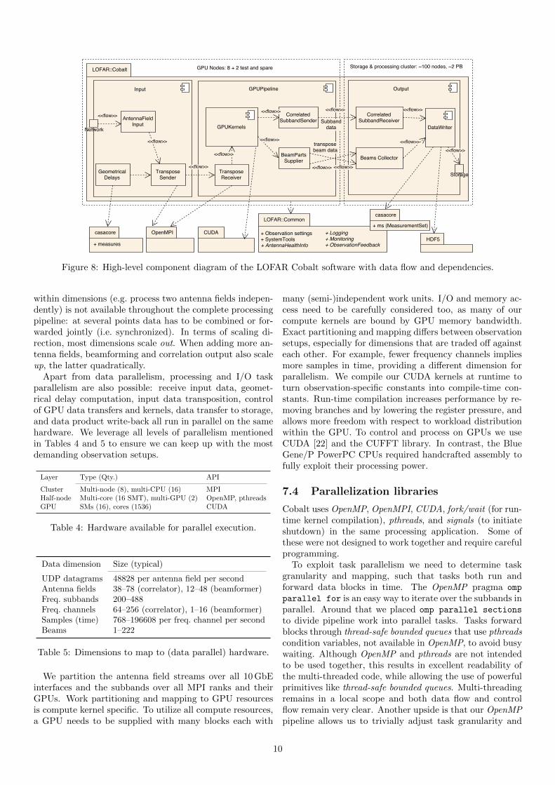
Figure 8: High-level component diagram of the LOFAR Cobalt software with data flow and dependencies.
within dimensions (e.g. process two antenna fields indepen-dently) is not available throughout the complete processingpipeline: at several points data has to be combined or for-warded jointly (i.e. synchronized). In terms of scaling di-rection, most dimensions scale out. When adding more an-tenna fields, beamforming and correlation output also scaleup, the latter quadratically.
Apart from data parallelism, processing and I/O taskparallelism are also possible: receive input data, geomet-rical delay computation, input data transposition, controlof GPU data transfers and kernels, data transfer to storage,and data product write-back all run in parallel on the samehardware. We leverage all levels of parallelism mentionedin Tables 4 and 5 to ensure we can keep up with the mostdemanding observation setups.
Layer Type (Qty.) API
Cluster Multi-node (8), multi-CPU (16) MPIHalf-node Multi-core (16 SMT), multi-GPU (2) OpenMP, pthreadsGPU SMs (16), cores (1536) CUDA
Table 4: Hardware available for parallel execution.
Data dimension Size (typical)
UDP datagrams 48828 per antenna field per secondAntenna fields 38–78 (correlator), 12–48 (beamformer)Freq. subbands 200–488Freq. channels 64–256 (correlator), 1–16 (beamformer)Samples (time) 768–196608 per freq. channel per secondBeams 1–222
Table 5: Dimensions to map to (data parallel) hardware.
We partition the antenna field streams over all 10 GbEinterfaces and the subbands over all MPI ranks and theirGPUs. Work partitioning and mapping to GPU resourcesis compute kernel specific. To utilize all compute resources,a GPU needs to be supplied with many blocks each with
many (semi-)independent work units. I/O and memory ac-cess need to be carefully considered too, as many of ourcompute kernels are bound by GPU memory bandwidth.Exact partitioning and mapping differs between observationsetups, especially for dimensions that are traded off againsteach other. For example, fewer frequency channels impliesmore samples in time, providing a different dimension forparallelism. We compile our CUDA kernels at runtime toturn observation-specific constants into compile-time con-stants. Run-time compilation increases performance by re-moving branches and by lowering the register pressure, andallows more freedom with respect to workload distributionwithin the GPU. To control and process on GPUs we useCUDA [22] and the CUFFT library. In contrast, the BlueGene/P PowerPC CPUs required handcrafted assembly tofully exploit their processing power.
7.4 Parallelization libraries
Cobalt uses OpenMP, OpenMPI, CUDA, fork/wait (for run-time kernel compilation), pthreads, and signals (to initiateshutdown) in the same processing application. Some ofthese were not designed to work together and require carefulprogramming.
To exploit task parallelism we need to determine taskgranularity and mapping, such that tasks both run andforward data blocks in time. The OpenMP pragma omp
parallel for is an easy way to iterate over the subbands inparallel. Around that we placed omp parallel sections
to divide pipeline work into parallel tasks. Tasks forwardblocks through thread-safe bounded queues that use pthreadscondition variables, not available in OpenMP, to avoid busywaiting. Although OpenMP and pthreads are not intendedto be used together, this results in excellent readability ofthe multi-threaded code, while allowing the use of powerfulprimitives like thread-safe bounded queues. Multi-threadingremains in a local scope and both data flow and controlflow remain very clear. Another upside is that our OpenMPpipeline allows us to trivially adjust task granularity and
10

count, without requiring a direct mapping to CPU cores.Downsides include the non-portability of our combined useof OpenMP and pthreads and that this use favors to have asmany threads as tasks, as otherwise some tasks have no ded-icated thread and thus may not empty their input queue,causing deadlock. As a result, some observation setups endup with an order of magnitude more threads than (logical)CPU cores. While there is room for CPU task management,the current OpenMP code is well readable and further op-timizations will not improve system capability, since CPUpower has never turned out to be a bottleneck in our system.
The Infiniband and GPU cards need the same CPU mem-ory used for DMA (Direct Memory Access) to be pinned andregistered with their driver. Pinning and registering comewith an overhead, which we have mitigated by allocatingall of these buffer during initialization. Both the MPI andGPU library offer interfaces to explicitly allocate memoryfor DMA, but only CUDA can mark an existing allocationas such, so we allocate shared buffers via MPI and thenregister them with CUDA.
Cobalt deals with a lot of mostly independent datastreams that are handled in parallel without interdepen-dencies. To optimally utilize the available hardware, everylevel of available parallelism needs to be exploited. However,none of the MPI libraries we looked into offered good multi-threading support, they were either not thread-safe, used aglobal lock, or failed to compile or run with fine grainedthread synchronization. We therefore wrap our MPI callswith a global lock, which turns out to be efficient enoughin combination with non-blocking sends and receives usingMPI Isend and MPI Irecv. We do need a separate pollingthread to frequently check for completion of pending trans-fers using MPI Testsome, otherwise MPI throughput suffers.
On the storage cluster, we distribute all subbands andbeams over the nodes. Some beamforming observationsneed full resolution, both spectral as well as temporal, whichlimits the number of beams that can be sent to storage dueto limited network bandwidth. In such setups, we have tostore each beam across multiple storage nodes. This split isless convenient for post-Cobalt processing, to be executedon the same cluster.
7.5 Signal processing with GPU kernels
This Subsection focuses on the digital signal processingGPU kernels shown in Figure 2 as executed within theGPUKernels component.
The correlator pipeline first channelizes subbands in apolyphase filter using FIR filters and FFT kernels. We carryFIR filter history samples across to the next block. Thepipeline then applies fine delay compensation and bandpasscorrection. This marks the end of processing per antennafield. To efficiently operate across antenna fields, the de-lay and bandpass kernel transposes data on write-back toGPU device memory. The last kernel computes the corre-lations of all pairs of antenna fields and averages in time toapproximately 1 s.
The beamformer pipeline forms many coherent and/orincoherent beam(s). Both beam types have the first four
kernels in common. Cobalt performs delay compensation,bandpass correction and beamforming at 256 channels persubband as a good compromise between time and frequencyresolution, and then transforms to the requested output res-olution, often 1 or 16 channels per subband. After bandpasscorrection, the coherent and/or incoherent specific steps ofthe beamforming pipeline execute. Coherent beamformingfirst adjusts the beam direction with a phase shift and sumsover antenna fields, then optionally computes Stokes param-eters, while incoherent beamforming first computes Stokesparameters and then sums over antenna fields. Coherentlyformed beams are more sensitive but cover a much smallersky area. During an observation many adjacent beams canbe formed to mosaic a somewhat larger sky area, althoughsome projects also add an incoherent beam to quickly searchfor bright signals [23]. If we do not convert to coherentStokes I (intensity only) or IQUV (full polarization), weretain complex voltage data with phase information allow-ing coherent dedispersion (after Cobalt). However, complexvoltages cannot be time averaged.
Due to differences in required frequency/time resolutionand averaging, the beamformer and correlator pipelines di-verge quickly in how they transform the incoming signal.This means that our beamformer cannot share initial stepswith the correlator and needs to reorder data often as shownin Figure 2.
All kernels operate on single-precision complex floating-point data, except for delay compensation, which usesmixed precision. Fine delay compensation (i.e. subsam-ple) uses the residual delay from coarse delay compensationby the TransposeSender. From the residual delays at thestart and end of a block, we compute the channel-dependentphase angles in double precision. Within a 1 s block theseangles can be interpolated linearly to obtain the angle foreach sample. Then back in single precision, we determinethe phase shift factor (sin/cos) and rotate back the phaseof each sample (complex multiplication). The beamformingkernel operates in a similar way to form beams with an off-set from the center. The Tesla K10 GPU has low doubleprecision throughput, but as long as the kernel is memorybound, the limited use of double precision has little impact.
Most kernel parameters are fixed throughout an obser-vation. We avoid using registers for these parameters andobtain more efficient kernel binaries by using runtime com-pilation supplying fixed parameters as C-style defines. Theresulting code is also more readable. We reduce GPU mem-ory usage by using a small number of buffers that the CUDAkernels alternate between as their in- and output.
The number of observation parameters supported byCobalt is large. This affects kernel complexity, kernel exe-cution configuration (CUDA block and grid dimensions), aswell as input/output data dimensions and some transposealternatives. This complexity cannot lead to observationfailures. To deal with execution configuration, GPU buffersizes and performance counters, we use a wrapper class foreach kernel. This also wraps the type unsafe argument pass-ing when launching a CUDA kernel. Each kernel unit testcovers the wrapped kernel. Furthermore, we centrally docu-ment which buffers are (re)used by which kernels and what
11
the array dimension order and sizes are.Although the development of highly optimized GPU ker-
nels is a critical Cobalt ingredient, the details are outside thescope of this article. For more insight into radio astronomysignal processing for Cobalt and beyond on various acceler-ator platforms, we refer the interested reader elsewhere [24].
8 Verification and validation
Before Cobalt could be taken into operational use it neededto be extensively tested and tuned. Regression testing andintegration happened continuously during (software) devel-opment. We determined science readiness during commis-sioning, a phase in the last part of development wheredomain experts and instrument engineers work closely to-gether towards system-wide integration, validation, tuningand performance characterization. Some of these tests arestill performed on one Cobalt node and LOFAR station be-fore deploying a new software release at full scale.
During Cobalt development we added about 400 tests in100 test programs. Some are unit tests, others test a feature,uncommon observation settings, across an interface, or acomplete Cobalt pipeline on a tiny amount of data. Aboutanother 100 unit tests were already in place for the LOFAR
Common package.Incrementally developing tests was a substantial amount
of work. Extending the test set and updating documenta-tion are part of delivering a new feature. What added to theeffort was dealing with tests that generally pass, but occa-sionally fail due to race conditions or non-real-time testingof real-time code. We used the Jenkins7 continuous integra-tion service to manage regression test builds. The extensiveuse of testing was critical for Cobalt to minimize regressions,both on component and on system level. Furthermore, testskept the code maintainable, by providing confidence andfreedom to improve or even refactor the Cobalt code.
Cobalt needs various non-default system settings to per-form well. System firmware (BIOS/EFI) and Linux kernelsettings needed to be tuned for performance and predictabil-ity, such as (minimum) network buffer sizes, CPU frequencyscaling, and mapping GPU and NIC interrupts to the CPUthey are linked to. We do not need to bind threads tocores within a socket, as long as we raise the CPU andI/O priority of threads receiving UDP input and writing tostorage. We also do not need to run a PREEMPT RT (real-time) patched Linux kernel. Our multi-homed network andVLANs to international stations required changes to ARPand routing settings to function correctly.
To get good performance for the input transpose via MPI,we needed to tune OpenMPI RDMA settings, for whichwe used the point-to-point tests from the SKaMPI bench-mark [25]. We also send transfers between CPU socketsover infiniband instead of directly between the CPUs viathe on-board QuickPath Interconnect.
Due to a performance regression that couldn’t be resolvedby reverting code commits, we had to rework the MPI trans-fer scheme. Instead of supporting all surrounding tasks in-
7https://jenkins.io/
dependently by scheduling their many point-to-point trans-fers, we applied message combining to send fewer but largermessages. While the new implementation solved the per-formance regression, this came at the cost of increased useof memory/cache bandwidth, and it introduced more de-pendencies between producers and consumers of MPI data.This is an example where we sacrificed an over-dimensionedresource (CPU cache/memory bandwidth) for a scarce re-source (development effort).
We have more examples of unexpected regressions dur-ing development and operations, but in general, debuggingperformance issues silently introduced with system softwareupdates, changed system & network settings, or replacedhardware was time consuming and difficult. To alleviatethis risk, we used performance and configuration verifica-tion scripts. This operational readiness check was especiallyuseful when the line between responsibilities for high per-formance software and system and network administrationblurred. When major hardware/software functionality hadpassed verification, the project scientist (i.e. an Observa-tory astronomer) was responsible for the validation effortto deliver a science capable instrument.
Radio telescopes essentially sample electromagnetic noise,including radio interference, and then perform stochasticsignal processing. Thus there was no reference output tobit-wise compare our output to. Moreover, the existingBlueGene-based system used double precision and a dif-ferent beamformer DSP filter chain. We therefore choseto analyze Cobalt output to comply with signal and noiseproperties required for the most demanding science cases.This proved the validity of the Cobalt output without hav-ing to be bit-wise equal to its Blue Gene predecessor.
In total, we planned and performed about 30 experimentsand worked with astronomers and software developers toget issues resolved and the system tuned and characterized.This effort took several months. Several experiments re-quired custom tools or software hooks and resolving issuescan be time consuming. This was a substantial project riskthat had to be mitigated with a solid development processand extensive and early testing.
During commissioning we observed no perceptible in-crease in system noise between the Blue Gene/P based cor-relator and beamformer and the new Cobalt implementa-tion. Considering the difference in numerical precision used– double precision in Blue Gene, single precision in Cobalt– this warrants some discussion. We note that these choiceswere driven primarily by the selected hardware, not by ne-cessity. Blue Gene was designed for double precision pro-cessing. There was no advantage in using lower precisionarithmetic. In contrast, the selected Nvidia K10 GPU isoptimised for single precision processing. As shown in Ta-ble 2, this GPU has abysmal double precision performance.Only delay compensation was considered vulnerable to thisloss of precision. Comparative analysis showed that singleprecision delay compensation led to an insignificant increaseof the total noise [26]. Calculating the delays themselvesdoes require double precision, this is the only part of theCobalt pipeline to do so.
12

9 Operational experience
Cobalt has been LOFAR’s secondary correlator since Jan-uary 2014 and its primary since March 2014. In May 2014,Cobalt also took over for beamformer observations.
We have collected statistics from three years of operationswith the Cobalt system. Figure 9 shows the relative numberof failed observations, with a break down into four failuremodes (N ≈ 23000). On average, 97.3% of submitted ob-servations were successful, clearly exceeding the requiredoperational availability of > 95% described in Section 5.
0
2
4
6
8
10
12
14
2014-Q1
2014-Q2
2014-Q3
2014-Q4
2015-Q1
2015-Q2
2015-Q3
2015-Q4
2016-Q1
2016-Q2
2016-Q3
2016-Q4
Faile
d o
bserv
ations (
%)
COBALT software failureOS/hardware failure
deployment errorsspecification errors
Figure 9: Failure modes of the Cobalt system over threeyears, and their occurrence in percentages.
Observations may start at any moment (24/7), but nor-mally, issue investigation starts the next working day. Ob-servations scheduled between the occurrence of an issue andthe start of the next working day may be adversely af-fected. The availabilities of other LOFAR sub-systems arenot shown, but were generally lower than that of Cobalt.However, these generally work on non-volatile data wherefailures do not automatically result in irretrievable data loss.
There was a noteworthy increase in availability after sixmonths in operations that can be attributed both to burn-in, as well as bug fixes in the Cobalt software and inthe scheduling system. Current operational Cobalt failuresmostly originate in network configuration or services, or innon-standard observation settings. Hardening and moni-toring the network and settings have reduced their impact(until such monitoring services fail). We have run into sev-eral Linux kernel bugs, unexpectedly exposed with new soft-ware releases or changes in work load. This includes a failuremode that caused occasional Linux kernel panics in our sys-tem, due to a memory allocation bug that was fixed with anewer kernel release. While this shows the value of keepinglow-level software updated and patched, we note that theregression mentioned in Section 8 may in part have beencaused by similar updates.
10 Summary and discussion
In this paper we presented the Cobalt GPU-based correla-tor and beamformer system for the LOFAR radio telescope.This system has successfully replaced the earlier Blue Genebased systems and has been in operations for almost fouryears now. We introduced the hardware design, as well asthe data flow-driven simplified system engineering processthat led to the final implementation. The challenges thatwere faced during prototyping were described, as well assome of the engineering efforts that were necessary to keepthe GPUs at an acceptable operating temperature. Finally,we showed some of the details of the software design, theverification process, and we discussed the operational expe-rience with the Cobalt system.
All nodes in Cobalt are identical and perform all neces-sary processing, there are no dedicated nodes for a task.This requires careful programming, as was shown in Sec-tions 7 and 8, but also makes for a highly efficient systemwith few idle components.
In contrast to similar papers describing software corre-lators, we focused heavily on the development process ofthe system design. We showed how hardware/software co-design, in close collaboration with a commercial partner,can lead to an efficient and affordable system. None of thesystems aimed at the HPC market were, for various rea-sons, suitable for our application. Close interaction betweenhardware vendor, hardware system designer and softwarearchitect in the design and prototyping phases was instru-mental in finding a suitable node design.
An Agile test-driven development process was introducedto ensure timely delivery of a system that is fit for pur-pose and meets the requirements described in Section 5.We also noted in Section 8 that the test-driven aspect hadgreat advantages in a system that cannot be completelydeterministic. As another example of co-design, the expe-riences with previous LOFAR beamformer systems showedthat a redesign of this component would better match therequirements of the majority of the science users. Whilethis delayed the delivery of the Cobalt beamformer slightly,we took this opportunity to improve LOFAR non-imagingcapability.
11 Impact
This project has generated a surprising amount of inter-est. Discussions with the University of Cambridge HPCteam, showed that they faced very similar issues, althoughtheir applications are very different. The University of Cam-bridge used our Cobalt hardware design as the basis for theirWilkes general purpose cluster8, which reached #2 on theNovember 2013 edition of the Green5009 list. The size ofthis cluster made this decision particularly note-worthy. Itwas a 128 node cluster, with just 8 nodes per rack, takingup 16 racks in total. At 4U per node, this was not a par-ticularly dense solution, but the, at the time, unique andabundant PCIe structure in these nodes was judged suffi-
8http://www.hpc.cam.ac.uk/services/wilkes.html9https://www.top500.org/green500/
13

ciently desirable to justify the additional expense in termsof rack space.
Informal presentations of the Cobalt design to several in-dustry partners, including senior Dell management, haveresulted in an increased awareness of radio astronomy asan eScience. It was difficult to find a chassis from any oneof the major vendors that could meet the requirements ofthe Cobalt project. It is hoped that our discussions withindustry, using this project as an example, will improve thesuitability of future HPC system designs for the next gen-eration of radio telescopes.
The initial design approach taken in this project, wherethe hardware is closely matched to the software require-ments, has since been successfully employed in the SKAScience Data Processor preliminary design [27].
12 Acknowledgements
The authors would like to thank the Center for Informa-tion Technology (CIT) at the University of Groningen andin particular Wietze Albers for his indispensable efforts inthe design and prototyping phase and Hopko Meijering andArjen Koers for their system and network administrationduring the development of Cobalt and its operational use.We thank Dell Netherlands, and Patrick Wolffs in particu-lar, for their close involvement in the prototyping phase ofthis project and their help in getting our custom cooling so-lution supported and certified. We would like to express ourappreciation to the anonymous reviewers for their detailedcomments on an earlier version of this manuscript.
ASTRON is an institute of NWO, the Netherlands Or-ganisation for Scientific Research.
References
[1] M.P. van Haarlem, M.W. Wise, and others Gunst. LO-FAR: The LOw-Frequency ARray. Astronomy and As-trophysics, 556, August 2013.
[2] John W. Romein, P. Chris Broekema, Ellen van Mei-jeren, Kjeld van der Schaaf, and Walther H. Zwart. As-tronomical Real-Time Streaming Signal Processing ona Blue Gene/L Supercomputer. In ACM Symposiumon Parallel Algorithms and Architectures (SPAA’06),pages 59–66, Cambridge, MA, July 2006.
[3] John W. Romein, P. Chris Broekema, Jan David Mol,and Rob V. van Nieuwpoort. The LOFAR Correlator:Implementation and Performance Analysis. In ACMSymposium on Principles and Practice of Parallel Pro-gramming (PPoPP’10), pages 169–178, Bangalore, In-dia, January 2010.
[4] Jan David Mol and John W. Romein. The LOFARBeam Former: Implementation and Performance Anal-ysis. In EuroPar’11, volume LNCS 6853, Part II, pages328–339, Bordeaux, France, August 2011.
[5] Peeyush Prasad, Folkert Huizinga, Eric Kooistra, et al.The AARTFAAC All Sky Monitor: System Design and
Implementation. Journal of Astronomical Instrumen-tation, 05(04), December 2016.
[6] S. M. Ord, B. Crosse, D. Emrich, et al. The MurchisonWidefield Array Correlator. Publications of the Astro-nomical Society of Australia, 32, 2015.
[7] J. Kocz, L. J. Greenhill, B. R. Barsdell, et al. Digi-tal Signal Processing Using Stream High PerformanceComputing: A 512-Input Broadband Correlator forRadio Astronomy. Journal of Astronomical Instrumen-tation, 4, March 2015.
[8] A. R. Parsons, D. C. Backer, G. S. Foster, et al.The Precision Array for Probing the Epoch of Re-ionization: Eight Station Results. The AstronomicalJournal, 139:1468–1480, April 2010.
[9] M. A. Clark, P. C. La Plante, and L. J. Greenhill.Accelerating Radio Astronomy Cross-Correlation withGraphics Processing Units. The International Journalof High Performance Computing Applications, 27:178–192, May 2012.
[10] Jayanta Roy, Yashwant Gupta, Ue-Li Pen, et al. A real-time software backend for the GMRT. ExperimentalAstronomy, 28(1):25–60, August 2010.
[11] A. Keimpema, M. M. Kettenis, S. V. Pogrebenko, et al.The SFXC software correlator for Very Long BaselineInterferometry: algorithms and implementation. Ex-perimental Astronomy, 39(2):259–279, 2015.
[12] A.T. Deller, S.J. Tingay, M. Bailes, and C. West.DiFX: A software correlator for very long baseline in-terferometry using multi-processor computing environ-ments. Publications of the Astronomical Society of thePacific, 119:318–336, February 2007.
[13] A. T. Deller, W. F. Brisken, C. J. Phillips, et al. DiFX-2: A More Flexible, Efficient, Robust, and PowerfulSoftware Correlator. Publications of the AstronomicalSociety of the Pacific, 123:275–287, March 2011.
[14] N. Denman, Mandana Amiri, Kevin Bandura, et al. AGPU-based Correlator X-engine Implemented on theCHIME Pathfinder. In 6th International Conference onApplication-specific Systems, Architectures and Proces-sors (ASAP), pages 35–40. IEEE, July 2015.
[15] Kamil Iskra, John W. Romein, Kazutomo Yoshii, andPete Beckman. ZOID: I/O-Forwarding Infrastruc-ture for Petascale Architectures. In ACM Sympo-sium on Principles and Practice of Parallel Program-ming (PPoPP’08), pages 153–162, Salt Lake City, UT,February 2008.
[16] John W. Romein. FCNP: Fast I/O on the BlueGene/P. In Parallel and Distributed Processing Tech-niques and Applications (PDPTA’09), volume 1, pages225–231, Las Vegas, NV, July 2009.
[17] Kazutomo Yoshii, Kamil Iskra, Harish Naik, Pete
14

Beckman, and P. Chris Broekema. Characterizing theperformance of “Big Memory” on Blue Gene Linux. InParallel Processing Workshops, 2009. ICPPW’09. In-ternational Conference on, pages 65–72. IEEE, 2009.
[18] Kazutomo Yoshii, Kamil Iskra, Harish Naik, PeteBeckman, and P. Chris Broekema. Performance andScalability Evaluation of “Big Memory” on Blue GeneLinux. International Journal of High PerformanceComputing Applications, 25:148–160, May 2011.
[19] R. V. van Nieuwpoort and J. W. Romein. CorrelatingRadio Astronomy Signals with Many-Core Hardware.International Journal of Parallel Processing, 1(39):88–114, February 2011.
[20] Ken Schwaber. Scrum development process. In JeffSutherland, Cory Casanave, Joaquin Miller, Philip Pa-tel, and Glenn Hollowell, editors, Business Object De-sign and Implementation, pages 117–134. Springer Lon-don, 1997.
[21] Ken Schwaber and Mike Beedle. Agile Software Devel-opment with Scrum. Prentice Hall PTR, Upper SaddleRiver, NJ, USA, 1st edition, 2001.
[22] John Nickolls, Ian Buck, Michael Garland, and KevinSkadron. Scalable parallel programming with CUDA.Queue, 6(2):40–53, March 2008.
[23] Thijs Coenen, Joeri van Leeuwen, Jason W. T. Hessels,et al. The LOFAR Pilot Surveys for Pulsars and FastRadio Transients. Astronomy and Astrophysics, 570,08 2014.
[24] John W. Romein. A Comparison of Accelerator Archi-tectures for Radio-Astronomical Signal-Processing Al-gorithms. In International Conference on Parallel Pro-cessing (ICPP’16), pages 484–489, Philadelphia, PA,August 2016.
[25] Ralf Reussner, Peter Sanders, and Jesper LarssonTraff. SKaMPI: A comprehensive benchmark for pub-lic benchmarking of MPI. Scientific Programming,10(1):55–65, 2002.
[26] Michiel A. Brentjens. Cobalt commissioning report.Technical report, ASTRON, September 2014.
[27] P. Chris Broekema, Rob V. van Nieuwpoort, andHenri E. Bal. The Square Kilometre Array ScienceData Processor. Preliminary compute platform design.Journal of Instrumentation, 10(07):C07004, 2015.
15