
Weld-in Valve Type EDR - Berkon Proses · General Description of the Weld-in Valve Type EDR The EDR...
16
Weld-in Valve Type EDR
Transcript of Weld-in Valve Type EDR - Berkon Proses · General Description of the Weld-in Valve Type EDR The EDR...
Weld-in Valve
Type EDR
2
EDR
Technical Description
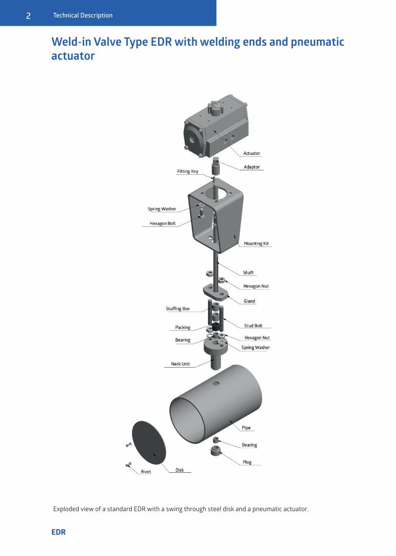
Weld-in Valve Type EDR with welding ends and pneumatic actuator
Exploded view of a standard EDR with a swing through steel disk and a pneumatic actuator.
Technische Beschreibung
3
EDR
Technical Description
Advantages at a glanceHandling Easy, depending on the accessories
Impermeability 99%, 99,5% and 99,95% compared to fully opened disk
Operating Temperature -100°C to +1100°C
Medium Compatibility Design and material selection according to your medium and further operating conditions, including: (aggressive) flue gas, dust-laden mediums, biogas or exhaust gases from biomass burning
Reliability Very low possibility of failure
Maintenance Characteristics Low maintenance
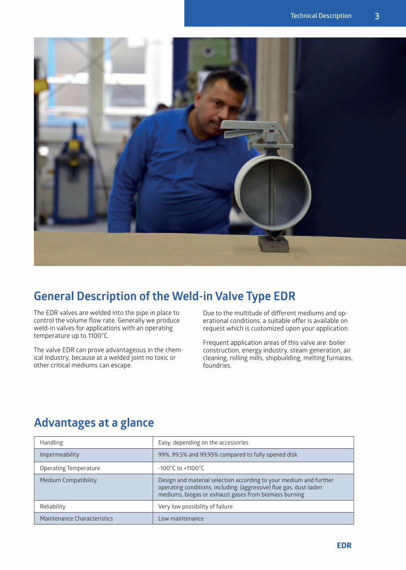
General Description of the Weld-in Valve Type EDRThe EDR valves are welded into the pipe in place to control the volume flow rate. Generally we produce weld-in valves for applications with an operating temperature up to 1100°C.
The valve EDR can prove advantageous in the chem-ical industry, because at a welded joint no toxic or other critical mediums can escape.
Due to the multitude of different mediums and op-erational conditions, a suitable offer is available on request which is customized upon your application.
Frequent application areas of this valve are: boiler construction, energy industry, steam generation, air cleaning, rolling mills, shipbuilding, melting furnaces, foundries.

4
EDR
Basic Information
Technical Description
Sizes: DN 17,3 - DN 533 (intermediate sizes viable) � Up to DN 2000 possible as a custom order
EDR as a weld-in valve
� With welding ends
Operation � With free shaft-end � Manual operation with a grid handle with locking mechanism or continuously variable fine adjustment � A corresponding shaft adaption with a DIN ISO 5211 mounting kit
� With a mounted actuator (pneumatic, electric or hydraulic)
Shaft Seal � Gland seal (Graphite, PTFE, Al-Si) � O-Rings or shaft seals (EPDM, FPM, NBR, PTFE) � Smooth running seal (Al-Si spring-loaded) � TA-Luft
Shaft Bearing � Sliding bearing (RG7, Rhyolite, PTFE, DU) � External fitting through flange bearings for smooth operating � External fitting over a friction bearing (EN-GJL-250CrNi) for high temperatures up to 1100°C
Impermeability Classes
� Approx. 99% impermeability in a disk swing through design
� Approx. 99,5% impermeability (metallic sealing) compared to fully opened valve disk in a design with a stop bar in the body
� Approx. 99,95% impermeability (with flexible seal) in designs with a stop bar and three sided jacketed gasket in the body
Operating Temperature � From -100°C up to +1100°C
Material � Steel (e.g. S235JR, S355JR) � Stainless steel (e.g. X5CrNi18-10, X6CrNiTi18-10, X6CrNiMoTi17-12-2, NiMo16Cr16Ti) � Heat resistant steel (e.g. X15CrNiSi20-12, X15CrNiSi25-21)

Technische Beschreibung
5
EDR
Material CombinationsTemperature up to 350°C up to 550°C up to 750°C up to 850°C up to 1100°CBody S235JR; S355JR X5CrNi18-10 X6CrNiMoTi17-12-2 X15CrNiSi20-12 X15CrNiSi25-21Disk S235JR; X5CrNi18-10 X5CrNi18-10 X6CrNiMoTi17-12-2 X15CrNiSi20-12 X15CrNiSi25-21Shaft MS (bis 150°C);
S235JR; X20Cr13X8CrNiS18-9; X6CrNiTi18-10; X20Cr13
X6CrNiMoTi17-12-2 X15CrNiSi20-12 X15CrNiSi25-21
Subject to modification
Closing TypesDisk swing through 99% impermeability compared to fully opened disk
With a stop bar in the body 99,5% impermeability compared to fully opened disk
With stop bar and gasket seal 99,95% impermeability compared to fully opened disk
With sealing air Up to 100% impermeability
Actuators and Actuator AccessoriesOperation AccessoryManual operation Grid handle, fine adjustment, worm gearPneumatic actuator Magnet valve, electro-mechanical end switch, inductive proximity switch
positioner 4...20mA, PROFIBUS, HART, etc.Elektric actuator End switch, revolution off-switch, position encoder 4…20mA, positioner,
PROFIBUS, HARTSecurity functions Fast closing and opening <1 sec through express airing or drop weightsCylinder Magnet valve, End position control
Subject to modification
Technical Description
Note: The material combinations listed here are standard combinations. The exact selection is made for customized designs and special requests in accordance with specifications or after consulting with you.
� Our valves are individually produced according to your needs. They are adjusted one hundred percent accord-ing to the operational conditions. That includes the specifications, material choice and operation.
� The Kv-values, impermeability and dynamic torque were tested in an FEM simulation.
� The valve EDR is simply welded with both ends in an existing pipeline.
Advantages of the EDR
6
EDR
Technical Data
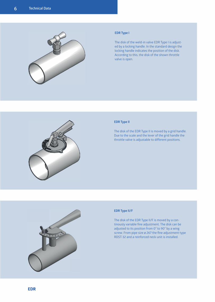
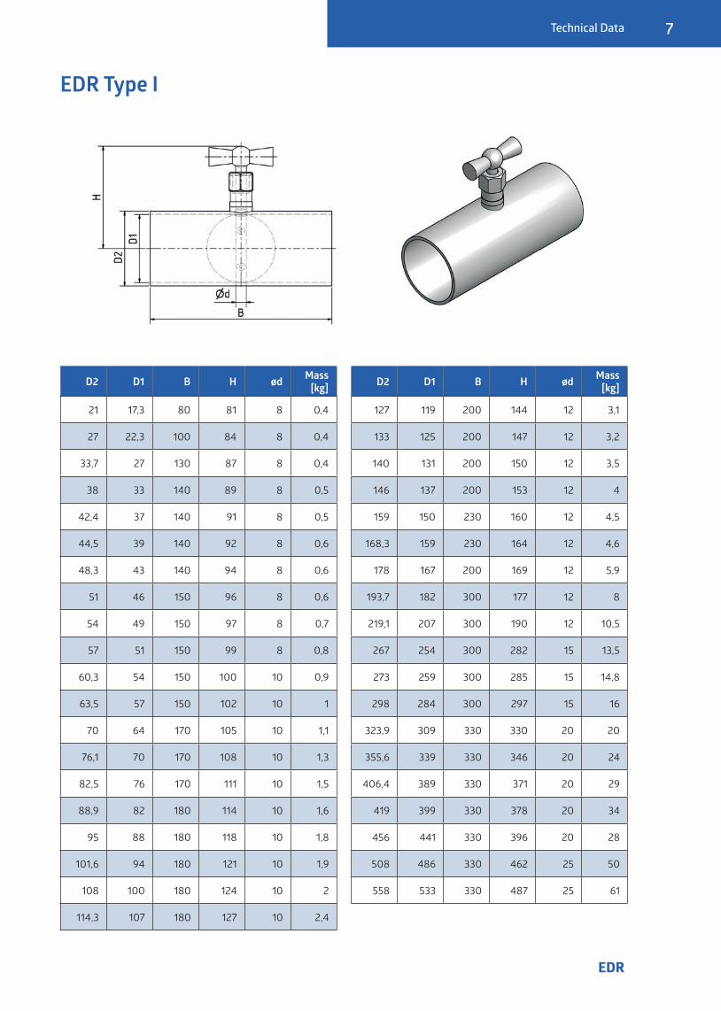
The disk of the weld-in valve EDR Type I is adjust-ed by a locking handle. In the standard design the locking handle indicates the position of the disk. According to this, the disk of the shown throttle valve is open.
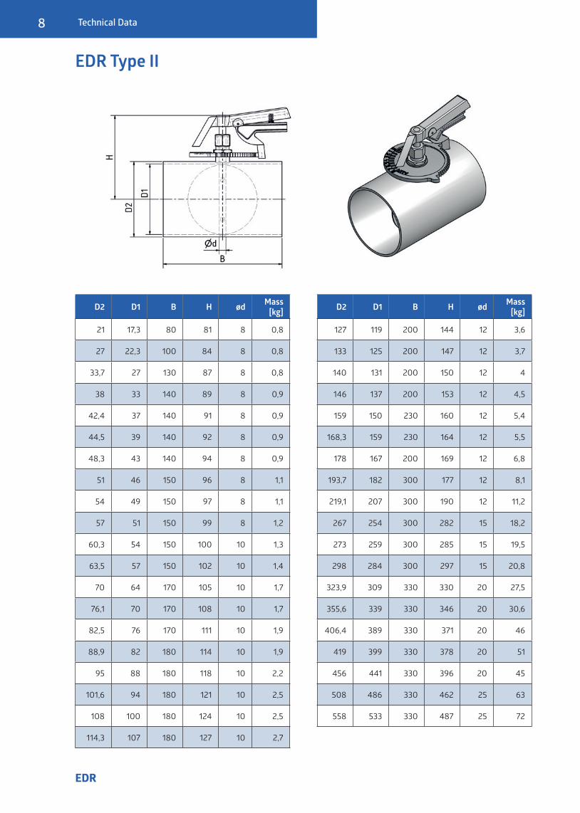
The disk of the EDR Type II is moved by a grid handle. Due to the scale and the lever of the grid handle the throttle valve is adjustable to different positions.
The disk of the EDR Type II/F is moved by a con-tinously variable fi ne adjustment. The disk can be adjusted to its position from 0° to 90° by a wing screw. From pipe size ø 267 the fi ne adjustment type RDST-32 and a reinforced neck-unit is installed.
EDR Type I
EDR Type II
EDR Type II/F
Technische Beschreibung
7
EDR
Technical Data
EDR Type I
D2 D1 B H ød Mass [kg]
21 17,3 80 81 8 0,4
27 22,3 100 84 8 0,4
33,7 27 130 87 8 0,4
38 33 140 89 8 0,5
42,4 37 140 91 8 0,5
44,5 39 140 92 8 0,6
48,3 43 140 94 8 0,6
51 46 150 96 8 0,6
54 49 150 97 8 0,7
57 51 150 99 8 0,8
60,3 54 150 100 10 0,9
63,5 57 150 102 10 1
70 64 170 105 10 1,1
76,1 70 170 108 10 1,3
82,5 76 170 111 10 1,5
88,9 82 180 114 10 1,6
95 88 180 118 10 1,8
101,6 94 180 121 10 1,9
108 100 180 124 10 2
114,3 107 180 127 10 2,4
D2 D1 B H ød Mass [kg]
127 119 200 144 12 3,1
133 125 200 147 12 3,2
140 131 200 150 12 3,5
146 137 200 153 12 4
159 150 230 160 12 4,5
168,3 159 230 164 12 4,6
178 167 200 169 12 5,9
193,7 182 300 177 12 8
219,1 207 300 190 12 10,5
267 254 300 282 15 13,5
273 259 300 285 15 14,8
298 284 300 297 15 16
323,9 309 330 330 20 20
355,6 339 330 346 20 24
406,4 389 330 371 20 29
419 399 330 378 20 34
456 441 330 396 20 28
508 486 330 462 25 50
558 533 330 487 25 61
8
EDR
Technical Data
EDR Type II
D2 D1 B H ød Mass [kg]
21 17,3 80 81 8 0,8
27 22,3 100 84 8 0,8
33,7 27 130 87 8 0,8
38 33 140 89 8 0,9
42,4 37 140 91 8 0,9
44,5 39 140 92 8 0,9
48,3 43 140 94 8 0,9
51 46 150 96 8 1,1
54 49 150 97 8 1,1
57 51 150 99 8 1,2
60,3 54 150 100 10 1,3
63,5 57 150 102 10 1,4
70 64 170 105 10 1,7
76,1 70 170 108 10 1,7
82,5 76 170 111 10 1,9
88,9 82 180 114 10 1,9
95 88 180 118 10 2,2
101,6 94 180 121 10 2,5
108 100 180 124 10 2,5
114,3 107 180 127 10 2,7
D2 D1 B H ød Mass [kg]
127 119 200 144 12 3,6
133 125 200 147 12 3,7
140 131 200 150 12 4
146 137 200 153 12 4,5
159 150 230 160 12 5,4
168,3 159 230 164 12 5,5
178 167 200 169 12 6,8
193,7 182 300 177 12 8,1
219,1 207 300 190 12 11,2
267 254 300 282 15 18,2
273 259 300 285 15 19,5
298 284 300 297 15 20,8
323,9 309 330 330 20 27,5
355,6 339 330 346 20 30,6
406,4 389 330 371 20 46
419 399 330 378 20 51
456 441 330 396 20 45
508 486 330 462 25 63
558 533 330 487 25 72

Technische Beschreibung
9
EDR
Technical Data
EDR Type II/F
D2 D1 B H ød Mass [kg]
21 17,3 80 81 8 0,7
27 22,3 100 84 8 0,7
33,7 27 130 87 8 0,7
38 33 140 89 8 0,7
42,4 37 140 91 8 0,8
44,5 39 140 92 8 0,8
48,3 43 140 94 8 0,9
51 46 150 96 8 0,9
54 49 150 97 8 0,9
57 51 150 99 8 1
60,3 54 150 100 10 1,1
63,5 57 150 102 10 1,2
70 64 170 105 10 1,3
76,1 70 170 108 10 1,4
82,5 76 170 111 10 1,6
88,9 82 180 114 10 1,8
95 88 180 118 10 1,9
101,6 94 180 121 10 2,2
108 100 180 124 10 2,4
114,3 107 180 127 10 2,4
D2 D1 B H ød Mass [kg]
127 119 200 144 12 3,2
133 125 200 147 12 3,4
140 131 200 150 12 3,7
146 137 200 153 12 4
159 150 230 160 12 4,9
168,3 159 230 164 12 5,3
178 167 200 169 12 6,6
193,7 182 300 177 12 7,9
219,1 207 300 190 12 11
267 254 300 282 15 20
273 259 300 285 15 22
298 284 300 297 15 23
323,9 309 330 330 20 29,4
355,6 339 330 346 20 32,5
406,4 389 330 371 20 47,9
419 399 330 378 20 53
456 441 330 396 20 47
508 486 330 462 25 65
558 533 330 487 25 74
10
EDR
Custom Designs
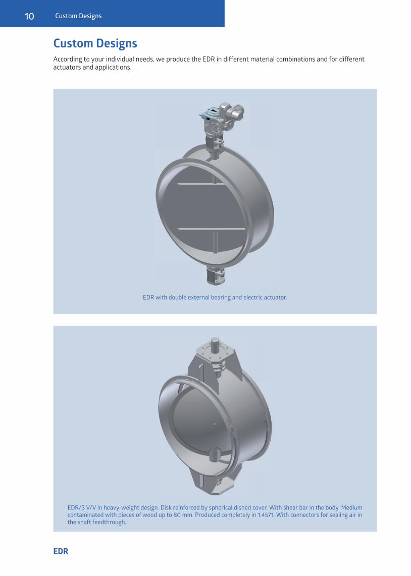
Custom DesignsAccording to your individual needs, we produce the EDR in different material combinations and for differentactuators and applications.
EDR with double external bearing and electric actuator.
EDR/S V/V in heavy-weight design. Disk reinforced by spherical dished cover. With shear bar in the body. Medium contaminated with pieces of wood up to 80 mm. Produced completely in 1.4571. With connectors for sealing air in the shaft feedthrough..
Technische Beschreibung
11
EDR
Custom Designs
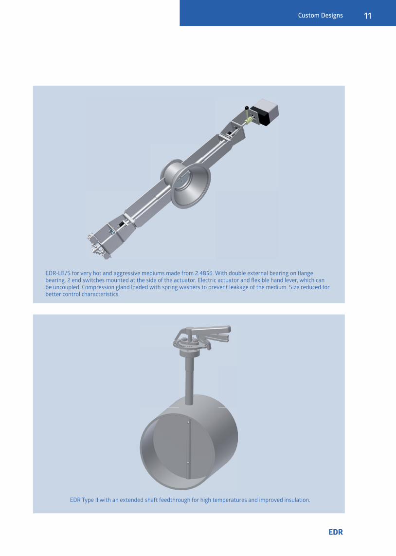
EDR-LB/S for very hot and aggressive mediums made from 2.4856. With double external bearing on fl ange bearing. 2 end switches mounted at the side of the actuator. Electric actuator and fl exible hand lever, which can be uncoupled. Compression gland loaded with spring washers to prevent leakage of the medium. Size reduced for better control characteristics.
EDR Type II with an extended shaft feedthrough for high temperatures and improved insulation.
12
EDR
References
References
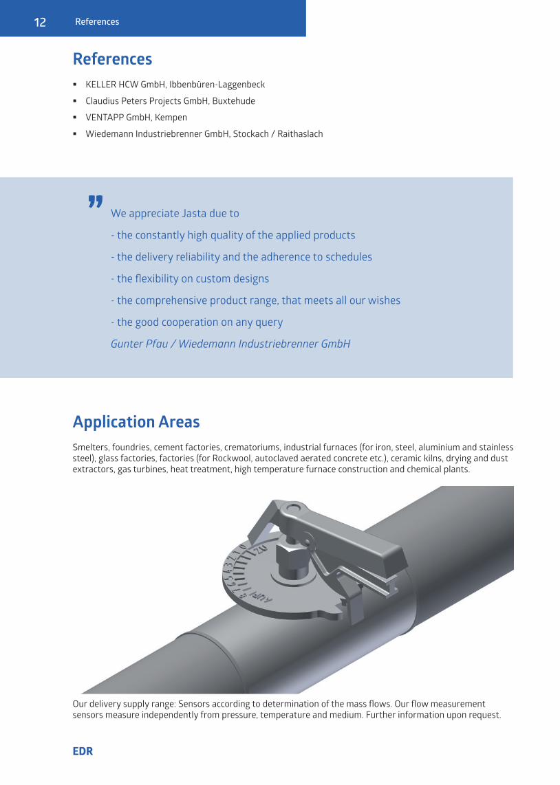
Application AreasSmelters, foundries, cement factories, crematoriums, industrial furnaces (for iron, steel, aluminium and stainlesssteel), glass factories, factories (for Rockwool, autoclaved aerated concrete etc.), ceramic kilns, drying and dust extractors, gas turbines, heat treatment, high temperature furnace construction and chemical plants.
� KELLER HCW GmbH, Ibbenbüren-Laggenbeck
� Claudius Peters Projects GmbH, Buxtehude
� VENTAPP GmbH, Kempen
� Wiedemann Industriebrenner GmbH, Stockach / Raithaslach
We appreciate Jasta due to
- the constantly high quality of the applied products
- the delivery reliability and the adherence to schedules
- the flexibility on custom designs
- the comprehensive product range, that meets all our wishes
- the good cooperation on any query
Gunter Pfau / Wiedemann Industriebrenner GmbH
„
Our delivery supply range: Sensors according to determination of the mass flows. Our flow measurementsensors measure independently from pressure, temperature and medium. Further information upon request.
Technische Beschreibung
13
EDR
Technical Data
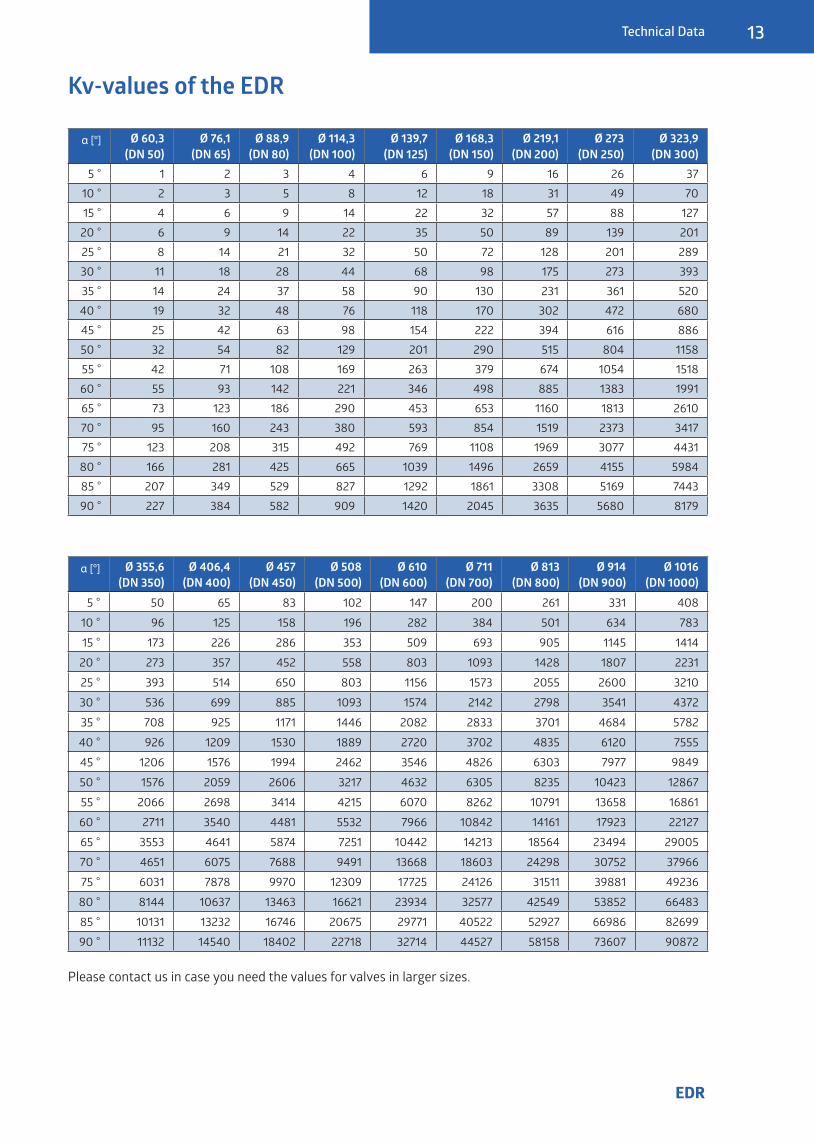
Kv-values of the EDR
α [°] Ø 355,6(DN 350)
Ø 406,4(DN 400)
Ø 457(DN 450)
Ø 508(DN 500)
Ø 610(DN 600)
Ø 711(DN 700)
Ø 813(DN 800)
Ø 914(DN 900)
Ø 1016(DN 1000)
5 ° 50 65 83 102 147 200 261 331 408
10 ° 96 125 158 196 282 384 501 634 783
15 ° 173 226 286 353 509 693 905 1145 1414
20 ° 273 357 452 558 803 1093 1428 1807 2231
25 ° 393 514 650 803 1156 1573 2055 2600 3210
30 ° 536 699 885 1093 1574 2142 2798 3541 4372
35 ° 708 925 1171 1446 2082 2833 3701 4684 5782
40 ° 926 1209 1530 1889 2720 3702 4835 6120 7555
45 ° 1206 1576 1994 2462 3546 4826 6303 7977 9849
50 ° 1576 2059 2606 3217 4632 6305 8235 10423 12867
55 ° 2066 2698 3414 4215 6070 8262 10791 13658 16861
60 ° 2711 3540 4481 5532 7966 10842 14161 17923 22127
65 ° 3553 4641 5874 7251 10442 14213 18564 23494 29005
70 ° 4651 6075 7688 9491 13668 18603 24298 30752 37966
75 ° 6031 7878 9970 12309 17725 24126 31511 39881 49236
80 ° 8144 10637 13463 16621 23934 32577 42549 53852 66483
85 ° 10131 13232 16746 20675 29771 40522 52927 66986 82699
90 ° 11132 14540 18402 22718 32714 44527 58158 73607 90872
α [°] Ø 60,3(DN 50)
Ø 76,1(DN 65)
Ø 88,9(DN 80)
Ø 114,3(DN 100)
Ø 139,7(DN 125)
Ø 168,3(DN 150)
Ø 219,1(DN 200)
Ø 273(DN 250)
Ø 323,9(DN 300)
5 ° 1 2 3 4 6 9 16 26 3710 ° 2 3 5 8 12 18 31 49 7015 ° 4 6 9 14 22 32 57 88 12720 ° 6 9 14 22 35 50 89 139 20125 ° 8 14 21 32 50 72 128 201 28930 ° 11 18 28 44 68 98 175 273 39335 ° 14 24 37 58 90 130 231 361 52040 ° 19 32 48 76 118 170 302 472 68045 ° 25 42 63 98 154 222 394 616 88650 ° 32 54 82 129 201 290 515 804 115855 ° 42 71 108 169 263 379 674 1054 151860 ° 55 93 142 221 346 498 885 1383 199165 ° 73 123 186 290 453 653 1160 1813 261070 ° 95 160 243 380 593 854 1519 2373 341775 ° 123 208 315 492 769 1108 1969 3077 443180 ° 166 281 425 665 1039 1496 2659 4155 598485 ° 207 349 529 827 1292 1861 3308 5169 744390 ° 227 384 582 909 1420 2045 3635 5680 8179
Please contact us in case you need the values for valves in larger sizes.
14
EDR
Glossary
Glossary
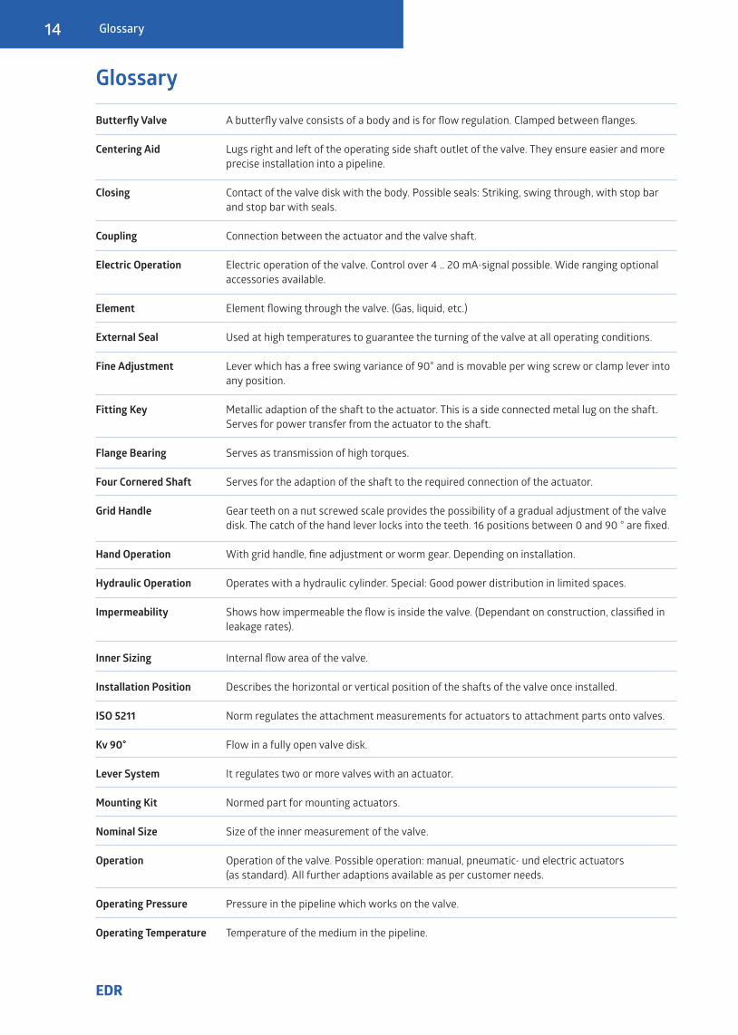
Butterfly Valve A butterfly valve consists of a body and is for flow regulation. Clamped between flanges.
Centering Aid Lugs right and left of the operating side shaft outlet of the valve. They ensure easier and more precise installation into a pipeline.
Closing Contact of the valve disk with the body. Possible seals: Striking, swing through, with stop bar and stop bar with seals.
Coupling Connection between the actuator and the valve shaft.
Electric Operation Electric operation of the valve. Control over 4 .. 20 mA-signal possible. Wide ranging optional accessories available.
Element Element flowing through the valve. (Gas, liquid, etc.)
External Seal Used at high temperatures to guarantee the turning of the valve at all operating conditions.
Fine Adjustment Lever which has a free swing variance of 90° and is movable per wing screw or clamp lever into any position.
Fitting Key Metallic adaption of the shaft to the actuator. This is a side connected metal lug on the shaft. Serves for power transfer from the actuator to the shaft.
Flange Bearing Serves as transmission of high torques.
Four Cornered Shaft Serves for the adaption of the shaft to the required connection of the actuator.
Grid Handle Gear teeth on a nut screwed scale provides the possibility of a gradual adjustment of the valve disk. The catch of the hand lever locks into the teeth. 16 positions between 0 and 90 ° are fixed.
Hand Operation With grid handle, fine adjustment or worm gear. Depending on installation.
Hydraulic Operation Operates with a hydraulic cylinder. Special: Good power distribution in limited spaces.
Impermeability Shows how impermeable the flow is inside the valve. (Dependant on construction, classified in leakage rates).
Inner Sizing Internal flow area of the valve.
Installation Position Describes the horizontal or vertical position of the shafts of the valve once installed. ISO 5211 Norm regulates the attachment measurements for actuators to attachment parts onto valves.
Kv 90° Flow in a fully open valve disk.
Lever System It regulates two or more valves with an actuator.
Mounting Kit Normed part for mounting actuators.
Nominal Size Size of the inner measurement of the valve.
Operation Operation of the valve. Possible operation: manual, pneumatic- und electric actuators (as standard). All further adaptions available as per customer needs.
Operating Pressure Pressure in the pipeline which works on the valve.
Operating Temperature Temperature of the medium in the pipeline.

Technische Beschreibung
15
EDR
Glossary
Packing Gasket Serves as the seal between the valve and shaft exit from the valve body. Can be produced in various ways. (EPDM, PTFE, TA-Luft eg.)
Pneumatic Operation Opening of the disk in the valve with a pneumatic actuator. With or without a spring setting. Control possible with a positioner.
RDST-32 Infinitely adjustable fine adjustment for larger valves.
Safety Position This is decided by the customer. Defines the position of the valve in an emergency.
Seal Flexible material in the valve. To improve the impermeability.
Sealing Air Used to seal the shaft up to 100%.
Service Defines the regular necessary readjustments (readjustment of the packaging, etc.). For the maintenance plan please see operating and maintenance manual.
SFD-6 Infinitely adjustable fine adjustment with a manual handle, used in smaller valves.
Shaft Bearing Bears of the shafts in the body.
Slide Bearing Turned sleeve, e.g. from red brass.
Step-seated Disk valve fitted in the body of the valve and stops the flow.
Stop bar Metallic valve stop in the valve. Serves to seal the valve.
Swing-through Valve without seals between the disk and body with defined ring gap.
TA-Luft German Clean Air Act (§48 BImSchG). Using a TA-Luft packing ensures 100% seal of the shaft bushing to the outside.

16
EDR
Test station at JASTA-ARMATUREN
CertificatesWe are certified for the following processes:
� ISO 9001
� AD 2000 HP0
� EN 3834-2
� SIL
� ATEX
Services for the Valves
We are happy to support you with various services to optimize the use of the valve.
� Determination of sound level
� Expertise on earthquake safety
� Strength calculation
� FEM calculation
� Leakage calculation
� Flow simulations
� Assembly and test run of your actuator
� Lacquering to your liking
JASTA-ARMATUREN GmbH & Co. KG
Levinstr. 156-16045356 EssenGermany
Phone: +49 - (0)201 - 86602-0Fax: +49 - (0)201 - 86602-21