Water and Sanitary Sewer Standard Specifications · City of Perry, Georgia Water and Sanitary Sewer...
136
City of Perry, Georgia Water and Sanitary Sewer Standard Specifications Revised October 16, 2012
Transcript of Water and Sanitary Sewer Standard Specifications · City of Perry, Georgia Water and Sanitary Sewer...
City of Perry, Georgia
Water and Sanitary Sewer
Standard Specifications
Revised October 16, 2012

TABLE OF CONTENTS
Clearing for Utilities 1-1
Water Distribution 2-1
Services 3-1
Sanitary Sewer 4-1
Sewer Manholes 5-1
Force Main and Related Piping 6-1
Pump Stations 7-1
Electrical 8-1
Removal and Replacement of Pavement 9-1
Water and Sewer Tapping Guidelines 10-1
SECTION NO. 1
CLEARING FOR UTILITIES
1.01 SCOPE
The work under this section of the Specifications consists of the furnishing of all materials and
equipment and performing all labor required for clearing of utility corridors.
1.02 CLEARING
The Contractor shall clear the corridor of only those items necessary to install the utility. These
shall include but not be limited to trees, stumps, brush, shrubs, rubbish and debris with the
exception of items designated to be left in place. Items outside the installation area shall not be
damaged.
A. Any trees, brush, stumps, wood and other debris must be disposed of by removing from
the site. Burning will be permitted only after a burn permit number is obtained
from the Environmental Protection Division of the Georgia Department of Natural
Resources and approval is granted by the Perry Fire Chief. The burn permit
number must be given to the fire chief prior to any burning.
PERRY, GEORGIA – WATER AND SANITARY SEWER SPECIFICATIONS 1-1

SECTION NO. 2
WATER DISTRIBUTION
2.01 PURPOSE
This section of the Specifications describes products to be incorporated into the water mains and
requirements for the installation and use of these items. The word “City” used herein shall
mean City of Perry or a designated representative.
2.02 GENERAL
A. Applicable Standards: Supply all products and perform all work in accordance with
applicable American Society for Testing and Material (ASTM), American Water Works
Association (AWWA), American National Standards Institute (ANSI), or other
recognized standards. Latest revisions of all standards are applicable. If requested by
the City of Perry, submit evidence that manufacturers have consistently produced
products of satisfactory quality and performance for a period of at least two (2) years.
B. Substitutions: Whenever a product is identified in the Specifications by reference to
manufacturer’s or vendor’s names, trade names, catalog numbers, etc., the Contractor
may freely choose from those referenced products which ones he wishes to provide.
Any item or product other than those so designated shall be considered a substitution.
The Contractor shall obtain prior approval from the City of Perry for all substitutions.
C. Warranty: Water distribution systems installed by Contractors which are accepted by
the City of Perry for ownership, operation and maintenance shall be warranted and
guaranteed for a period of one (1) year from the date of final acceptance that the
completed system is free from all defects due to faulty products or workmanship and
that the Contractor shall make such corrections as may be necessary by reason of such
defects upon notice by the Owner.
D. City of Perry representatives shall inspect all fittings, valves, fire hydrants and
thrust blocks before backfilling. Contractor shall notify the City in advance of
inspections.
2.03 CONSTRUCTION DRAWINGS
The term “construction drawings” shall mean drawings, prints, descriptive literature, test
reports, samples, calculations, schedules, material lists, information and items of similar
meaning.
PERRY, GEORGIA – WATER AND SANITARY SEWER SPECIFICATIONS 2-1
A. Submittals Required: The Contractor shall furnish to the City of Perry, for review
in accordance with the procedure outlined below, drawings and descriptive

literature for all manufactured or fabricated products. Additional information, such
as special drawings, schedules, calculations and tests, shall be provided as specifically
requested by the City.
B. Contractor’s Review: The Contractor shall review and check drawings and
submittals. He shall indicate his review by initials and date. The Contractor shall
furnish the City with a minimum of three (3) copies of all submittals. A transmittal
form shall accompany each submittal or group of submittals.
C. Review: All submittals will be reviewed, stamped and dated by the City before they are
returned to the Contractor.
One (1) copy of reviewed submittals will be returned to the Contractor and the
remaining copies retained by the City.
Submittals requiring minor corrections will be so noted. Drawings must be resubmitted
for review prior to installation or use of products.
D. Drawings for Construction: The Contractor shall maintain at the job site a
complete set of construction drawings. The Contractor shall maintain
throughout the project a set of “As-Built” mark-up plans indicating the
locations of valves, tees, etc. with field measurements. The developer/owner is
to provide the City of Perry with one full printed set of as-built construction
plans and an electronic copy of the as-built construction plans on CD-ROM
in the AutoCad 14 format or a later version. The printed set and CD-ROM
are to be provided upon completion of the project and before final
acceptance.
2.04 MATERIALS
Furnish all pipe, fittings, valves, tapping sleeves and valves, hydrants and all other materials
required for completion of the work. All materials shall be made in AMERICA. Furnish
materials in accordance with the following:
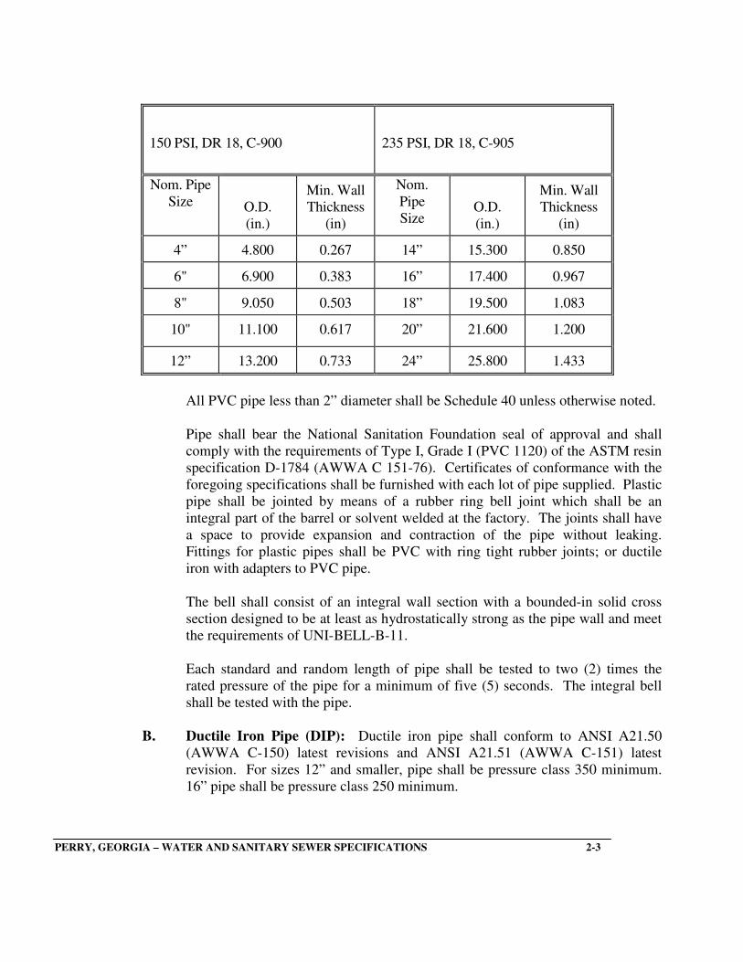
A. Polyvinyl Chloride Pipe: Pipe shall be PVC Class 150, DR 18, C-900 for 12” and
smaller and Class 235, DR 18, C-905 for 14” and larger. All pipe shall conform to
ASTM D-2241 and be installed in accordance with ASTM-D-2321. Joints shall be in
accordance with ASTM D-3036. Sizes and dimensions shall be as follows:
PERRY, GEORGIA – WATER AND SANITARY SEWER SPECIFICATIONS 2-2
150 PSI, DR 18, C-900
235 PSI, DR 18, C-905
Nom. Pipe
Size
O.D.
(in.)
Min. Wall
Thickness
(in)
Nom.
Pipe
Size
O.D.
(in.)
Min. Wall
Thickness
(in)
4” 4.800 0.267 14” 15.300 0.850
6" 6.900 0.383 16” 17.400 0.967
8" 9.050 0.503 18” 19.500 1.083
10" 11.100 0.617 20” 21.600 1.200
12” 13.200 0.733 24” 25.800 1.433
All PVC pipe less than 2” diameter shall be Schedule 40 unless otherwise noted.
Pipe shall bear the National Sanitation Foundation seal of approval and shall
comply with the requirements of Type I, Grade I (PVC 1120) of the ASTM resin
specification D-1784 (AWWA C 151-76). Certificates of conformance with the
foregoing specifications shall be furnished with each lot of pipe supplied. Plastic
pipe shall be jointed by means of a rubber ring bell joint which shall be an
integral part of the barrel or solvent welded at the factory. The joints shall have
a space to provide expansion and contraction of the pipe without leaking.
Fittings for plastic pipes shall be PVC with ring tight rubber joints; or ductile
iron with adapters to PVC pipe.
The bell shall consist of an integral wall section with a bounded-in solid cross
section designed to be at least as hydrostatically strong as the pipe wall and meet
the requirements of UNI-BELL-B-11.
Each standard and random length of pipe shall be tested to two (2) times the
rated pressure of the pipe for a minimum of five (5) seconds. The integral bell
shall be tested with the pipe.
B. Ductile Iron Pipe (DIP): Ductile iron pipe shall conform to ANSI A21.50
(AWWA C-150) latest revisions and ANSI A21.51 (AWWA C-151) latest
revision. For sizes 12” and smaller, pipe shall be pressure class 350 minimum.
16” pipe shall be pressure class 250 minimum.
PERRY, GEORGIA – WATER AND SANITARY SEWER SPECIFICATIONS 2-3

Joints shall be push-on type for pipe and standard mechanical or flanged joints
for fittings unless otherwise noted. Push-on and mechanical joints shall conform
to AWWA C111. Restrained joint pipe (RJP) shall be either the bolted joint type
or modified push-on type with joint restraint using ductile iron components.
Restrained joint pipe where required shall be American, U.S. Pipe, McWane, or
equal.
Provide the appropriate gaskets for mechanical or flange joints. Gaskets for
flange joints shall be made of 1/8-inch thick cloth reinforced rubber; gaskets may
be ring type or full-face type.
Provide the necessary bolts for mechanical or flange connections. Bolts for
flange connections shall be steel with American Regular unfinished square or
hexagon heads. Nuts shall be steel with American Standard Regular hexagonal
dimensions, as all specified in ANSI B 17.2. All bolts and all nuts shall be
threaded in accordance with ANSI B.1.1. Coarse Thread Series, Class 2A and 2B
fit.
All pipe shall be furnished in lengths of at least 18 feet.
Acceptance will be on the basis of the Engineer’s review and the manufacturer’s
written certification that the pipe was manufactured and tested in accordance
with the applicable standards.
C. Ductile Iron Fittings: Ductile iron fittings shall be compact weight, short body
ductile iron fittings for 350 psi water pressure plus water hammer, conforming to
ASA Specification A21.10 with mechanical joints conforming to ASA
Specification A21.11, cement lined.
D. Gate Valves (GV): Gate valves shall be mechanical joint end, resilient seat,
parallel seat, iron body, bronze mounted, non-rising stem with O-ring stem seals,
open left. Gate valves 2” through 12” shall be designated for a working pressure
of 200 psi and a test pressure of 400 psi. Valves 14” and larger shall be designed
for a water working pressure of 150 psi and a test pressure of 300 psi. Valves 2”
through 12” will be designed for installing in a vertical position. Valves larger
than 14” will be designed for a horizontal installation and equipped with bevel
gearing, gear case, tracks, rollers, scrapers and by-pass valves. Gate valves shall
conform to AWWA Standard Specification C-500, latest revision for “Ordinary
Water Works Service” and shall be Mueller No. A2370-20, American Darling
No. 85, or an approved equal.
Resilient seat gate valves conform to AWWA Standard Specification C-509.
PERRY, GEORGIA – WATER AND SANITARY SEWER SPECIFICATIONS 2-4

E. Valve Boxes (VB): All gate valves shall be equipped with valve boxes. Valve
boxes shall be heavy roadway type. The valve boxes shall be cast iron two-piece
slip or screw type with drop covers. The valve boxes shall be adjustable to six
inches (6”) up or down from the nominal required cover over the pipe.
F. Tapping Sleeves and Valves (TS&V): Tapping sleeves shall be ductile iron
of the split sleeve mechanical joint type or fabricated stainless steel
according to application. All tapping saddles shall be pressure tested after
installation and before main is cored. Valves shall be gate valves furnished in
accordance with the specifications shown above with flanged connection to the
tapping sleeve and mechanical joint connection the branch pipe. The necessary
bolts, glands and gaskets shall be furnished.
G. Fire Hydrants (FH): All new fire hydrants shall conform to the requirements of
AWWA C-502 for 150 psi working pressure. Hydrants shall be the compression
type closing with line pressure. The valve opening shall be five and one-
quarter inches (5 ¼”).
In the event of a traffic accident, the hydrant barrel shall break away from the
standpipe at a point above grade and in a manner which will prevent damage to
the barrel and stem, preclude opening of the valve and permit rapid and
inexpensive restoration without digging or cutting off the water. The means for
attaching the barrel to the standpipe shall permit facing the hydrant a minimum
of eight different directions.
New hydrants shall be fully bronze mounted with all working pars of bronze.
Valve seat shall be bronze and shall screw into a bronze retainer.
All working parts, including the seat ring, shall be removable through the top
without disturbing the barrel of the hydrant.
The operating nut shall match those on the existing hydrants. The operating
threads shall be totally enclosed in an operating chamber separated from the
hydrant barrel by a rubber O-ring stem seal and lubricated by a grease or oil
reservoir. A stop nut shall be positioned in the top operating mechanism so that
the valve cannot contact the bottom of the shoe when fully open.
New hydrants shall be a non-freezing design and provided with a simple,
positive and automatic drain which shall be fully closed whenever the main valve
is opened.
PERRY, GEORGIA – WATER AND SANITARY SEWER SPECIFICATIONS 2-5
Hose and pumper connections shall be breech-locked, pinned and then caulked
with lead; or threaded and pinned to seal them permanently into the hydrant
barrel. Each hydrant shall have two (2) each 2 ½” hose connections using
Perry Standard threads and one (1) each 4” pumper connection with
National Standard threads. Equip each connection with cap and chain.
New hydrants shall be furnished with a mechanical joint shoe connection to the
spigot of the six inch (6”) hydrant lead.
Minimum depth of bury shall be four feet (4’) on vertical riser stem. Provide extension section where necessary for vertical installation and in
accordance with manufacturer’s recommendations.
Provide where indicated or directed, an adjustable six inch (6”) fire hydrant lead
pipe equivalent to GRADELOK. Adjustable lead pipe shall adjust to a
maximum of 24 vertical inches. Pipe shall be ductile iron and meet the
requirements of AWWA C-153/ANSI A21.53. Pipe shall be tar coated outside
and cement-lined inside as per AWWA C-104/ANSI A21.4.
All new and relocated fire hydrants shall be painted. All outside surfaces of the
barrel above grade shall be painted as follows:
BASE: Safety Yellow equal to Martin Senour Tough Coat, High Gloss
Alkyd, Gloss Yellow, #727-1819.
TOP: Silver equal to Martin Senour Tough Coat, Chrome Aluminum,
#727-1316.
New hydrants shall be Mueller Centurion or M & H.
H. Polyethylene Film Encasement: Each location of a ductile iron fitting within
ten feet (10’) of a natural gas line with cathodic protection will require
polyethylene encasement.
The polyethylene film shall be manufactured of virgin polyethylene material
conforming to the requirements of ASTM Standard Specifications D-1248-78.
Polyethylene film shall have a minimum thickness of 0.008 inches.
The polyethylene encasement shall prevent contact between the pipe and the
surrounding backfill and/or bedding material but it is not intended to be a
completely airtight and watertight enclosure. Overlaps shall be secured by the
use of adhesive tape, plastic string or other material capable of holding the
polyethylene encasement in place until backfilling operations are complete.
PERRY, GEORGIA – WATER AND SANITARY SEWER SPECIFICATIONS 2-6

I. Pipeline Casing Spacers: Each pipeline casing spacers shall be two (2) piece
14 gauge T-304 stainless steel with corrosion resistant clamps for carrier pipe.
The runners shall be ultra high molecular weight polymer to resist abrasion and
sliding wear and configured to center the carrier pipe in the casing pipe with
adequate support.
Spacing shall be as recommended by the manufacturer. Spacers shall be
Cascade or an approved equal.
J. Tie Rods, Bolts and Washers
1. Minimum rod size shall be __” in diameter. Table below gives
numbers of various diameter rods required for a given pipe size. When
using bolting rods, the diameter of mechanical joint bolts limits the size
of rods to ¾.
Rod Number – Diameter Combinations
NUMBER OF RODS
Pipe Size 5/8 Inches ¾ Inches 7/8 Inches 1 Inch
4" 2 -- -- --
6" 2 -- -- --
8" 3 2 -- --
10" 4 3 2 --
12" 6 4 3 2
14" 8 5 4 3
16" 10 7 5 4
Table has been derived using pressure of 225 psi and design stress of 25,000 psi.
2.05 HANDLING MATERIALS
A. Unloading: Furnish equipment and facilities for unloading, handling, distributing and
storing pipe, fittings, valves and accessories. Make equipment available at all times for use in unloading. Do not drop or dump materials. All materials dropped or dumped will be subject to rejection without additional justification.
B. Handling: Handle pipe, fittings, valves and accessories carefully to prevent shock or
damage. Handle pipe by rolling on skids, forklift or front loader. Do not use material
damaged in handling.
C. Distribution: Distribute and place pipe and materials to not interfere with traffic. Do
not string pipe more than 1,000 feet beyond the area where pipe is being laid. Do not
obstruct drainage ditches.
PERRY, GEORGIA – WATER AND SANITARY SEWER SPECIFICATIONS 2-7

D. Storage: Store all pipe which cannot be distributed along the route. Make
arrangements for the use of suitable storage areas. Do not interfere with other
contractors right to access.
2.06 CONSTRUCTION ALONG HIGHWAYS, STREETS AND ROADWAYS
Install pipe lines and accessories along highways, streets and roadways in accordance with the
applicable regulations of the City of Perry, Houston County and/or the Department of
Transportation with reference to construction operations, safety, traffic control, road
maintenance and repair.
A. Protection of Traffic: Provide and maintain suitable signs, barricades and lights for
protection of traffic.
Replace all highway signs removed for construction as soon as possible. Do not close or
block any highway, street, or roadway without first obtaining permission from the
proper authorities.
Provide flagmen to direct and expedite the flow of traffic.
B. Construction Operations: Perform all work along highways, streets and roadways to
least interfere with traffic.
1. Stripping: Where the pipe line is laid along road shoulders, strip and stockpile
all sod, topsoil and other material suitable for shoulder restoration.
2. Trenching, Laying and Backfilling: Do not open the trench any further ahead
of pipe laying operations than is necessary. Backfill and remove excess material
immediately behind laying operations. Complete excavation and backfill for any
portion of the trench in the same day.
3. Shaping: Reshape damaged slopes, side ditches and ditch lines immediately
after completing backfilling operations. Replace topsoil, sod and any other
materials removed from shoulders.
C. Excavated Materials: Do not place excavated material along highways, streets and
roadways in a manner which obstructs traffic. Sweep all scattered excavated material
off of the pavement.
D. Drainage Structures: Keep all side ditches, culverts, cross drains and other drainage
structures clear of excavated material and free to drain at all times.
PERRY, GEORGIA – WATER AND SANITARY SEWER SPECIFICATIONS 2-8

E. Maintaining Highways, Streets, Roadways and Driveways: Maintain streets,
highways and roadways in suitable condition for movement of traffic until completion
and final acceptance of the work. Use steel running plate to maintain traffic until
pavement replacement is completed.
Note: Traffic must be maintained at all times. When one lane is closed, flagmen must
be utilized to maintain traffic flow.
Repair all driveways that are cut or damaged immediately. Maintain them in a suitable
condition for use until completion and final acceptance of the work.
2.07 EXISTING UNDERGROUND UTILITIES AND OBSTRUCTIONS
It is the responsibility of the Contractor to locate all existing utilities along the path of his
construction. His drawings shall indicate underground utilities or obstructions that are known to
exist. Where these or unforeseen underground utilities are encountered, the location and
alignment of the water main may be changed upon written approval of the Engineer and the
Owner to avoid interference.
2.08 CONNECTIONS TO EXISTING PIPE LINE
Before laying pipe, the Contractor shall locate the points of connection to existing pipe lines and
uncover as necessary for the City to confirm the nature of the connection to be made. The
Contractor shall furnish materials and made the connection to all existing pipe lines. The
Contractor will be observed by the City during construction of tie-ins. The Contractor shall
use all available practices and resources to minimize the time the customers are without water.
The Contractor shall notify the City of water outages at least 24 hours in advance.
2.09 LAYING PVC PIPE
A. General: Unless specifically indicated on the plans or called for in the specifications,
PVC water lines shall be constructed of rubber gasket joint pipe with mechanical joint
fittings and valves.
B. Construction Methods
1. Field Inspections: All pipe and accessories shall be laid, jointed, tested for
defects and for leakage with pressure and chlorinated in the manner herein
specified. The City’s representative shall inspect all fittings, valves and hydrants
before backfilling. Thrust block shall also be inspected. The Contractor shall be
responsible for notifying the City in advance of each inspection.
PERRY, GEORGIA – WATER AND SANITARY SEWER SPECIFICATIONS 2-9
2. Handling Pipe and Accessories
a. Care: PVC pipe, fittings, valves and other accessories shall be unloaded
at the point of delivery, hauled to and distributed at the site of the project
by the Contractor; they shall at all times be handled with care to avoid
damage. In loading and unloading they shall be lifted by hoists or slid or
towed on skidways in such a manner as to avoid shock. Under no
circumstances shall they be dropped. Pipe handled on skidways must not
be skidded or rolled against pipe already on the ground.
b. At Site of Work: In distributing the material at the site of the work, each
piece shall be unloaded opposite or near the place where it is to be laid in
the trench and shall be laid on high ground so that it will not be in a
drainage way.
c. Bell Ends, How Faced: Pipe shall be placed on the site of the work
parallel with the trench alignment and with the bell ends facing the
direction in which the work will proceed, unless otherwise directed by the
Engineer.
d. Pipe Kept Clean: The interior of all pipe, fittings and other accessories
shall be kept free from dirt and foreign matter at all times.
3. Alignment and Grade
a. General: All pipe shall be laid and maintained in the required lines and
grades with fittings and valves at the required locations, joints centered
and spigots home, and with all valve stems plumb.
b. Depth of Pipe: The top of the barrel of the pipe shall have a
minimum cover of forty-eight inches (48”).
Whenever water mains cross existing sanitary sewer lines, a minimum
vertical separation of eighteen inches (18”) must be maintained between
the two pipes.
4. Excavation and Preparation of Trench
a. Description: The trench shall be dug to the alignment and depth
requirement and not to exceed 200 feet in advance of the pipe laying.
The trench shall be braced if work therein safely and efficiently. It is
essential that the discharge from any pumps be led to natural drainage
channels, drains or storm sewers.
PERRY, GEORGIA – WATER AND SANITARY SEWER SPECIFICATIONS 2-10

b. Width: Minimum width of trench shall be eighteen inches (18”) or six
inches (6”) outside the barrel of the pope on each side of pipe. Maximum
width of trench shall be nine inches (9”) outside the barrel of the pipe on
each side of pipe. Sides of trench shall be dug and maintained
substantially vertical to a height of twelve inches (12”) above the pipe.
c. Pipe Foundation: The pipe shall be laid upon a sound earthen
foundation cut true and even so that the barrel of the pipe will have a
bearing for its full length. If unsuitable foundation material is
encountered, crushed stone stabilization will be required. Crushed stone
trench stabilization shall be No. 57 stone.
d. Correcting Faulty Grade: Any part of the trench excavated below
grade shall be corrected with approved materials, thoroughly compacted.
e. Bell Holes, Required: Bell holes of ample dimensions shall be dug in
trenches at each joint to permit the joint to be made properly.
f. Braced and Sheeted Trenches: Wherever necessary to prevent caving,
excavations shall be adequately sheeted and braced. Where sheeting and
bracing are used, the trench width shall be increased accordingly. Trench
sheeting shall remain in place until the pipe has been laid, tested for
defects and repaired if necessary, and the earth around it compacted to a
depth of two feet (2’) over the top of the pipe. All methods shall comply
with latest OSHA standards.
g. Care of Surface Materials for Re-Use: If local conditions permit their
re-use, all surface materials suitable for re-use in restoring the surface
shall be kept separate from the general excavation material.
h. Manner of Piling Excavated Materials: All excavated materials shall
be piled in a manner that will not endanger the work and that will avoid
obstructing sidewalks and driveways. Gutters shall be kept clear or other
provisions made for street drainage.
i. Trenching by Machine or by Hand: The use of trench digging
machinery will be permitted except in places where operation of same
will cause damage to existing structures above or below ground; in which
case hand methods shall be employed. Excavation shall be made by
ladder type machine or backhoe.
PERRY, GEORGIA – WATER AND SANITARY SEWER SPECIFICATIONS 2-11

5. Pipe Handling
a. Manner of Hauling Pipe and Accessories: Proper implements, tools
and facilities shall be provided and used by the Contractor for the safe
and convenient execution of the work. All pipe, fittings and valves shall
be carefully lowered into the trench piece by piece by means of derrick
ropes or other suitable tools or equipment in such a manner as to prevent
damage to pipe or pipe coating. Under no circumstances shall pipe or
accessories be dropped or dumped into the trench.
b. Inspection: Before lowering and while still suspended, the pipe shall be
inspected for defects. Any defective, damaged or unsound pipe shall be
rejected.
c. Pipe Kept Clean: All foreign matter or dirt shall be removed from the
pipe and shall be kept clean by approved means during and after laying.
d. Laying of the Pipe: The spigot shall be centered in the bell, the pipe
forced “home” and brought into true alignment; it shall be secured there
by earth carefully tamped under and on each side of it, except at the bell
holes. Care shall be taken to prevent dirt from entering the joint space.
No “blocking up” of pipe or joints will be permitted. The joint shall be
made as hereinafter described.
e. Trench Water Entering Pipe: At times when pipe laying is not in
progress, the open ends of the pipe shall be closed by approved means
and no trench water shall be permitted to enter the pipe.
f. Cutting Pipe: Cutting of pipe for inserting valves, fittings closure pieces
shall be done in a neat workmanlike manner without damage to the pipe.
g. Bell Ends Face Direction of Laying: Unless otherwise directed, pipe
shall be laid with bell ends facing in the direction of laying; and for lines
on an appreciable slope, bells shall, at the direction of the Engineer, face
up-grade.
h. Permissible Deflections at Joints: Wherever necessary to deflect pipe
from a straight line either in the vertical or horizontal plane to avoid
obstructions, mechanical joint fittings shall be used. Bending the pipe
will not be allowed.
PERRY, GEORGIA – WATER AND SANITARY SEWER SPECIFICATIONS 2-12

i. Unsuitable Conditions for Laying Pipe: No pipe shall be laid in
water or when the trench conditions or weather is unsuitable for
such work.
6. Jointing Pipe – Mechanical Joints: The following steps shall be taken in
making mechanical joints:
a. All lumps, blisters and excess coal-tar enamel shall be removed from
socket and spigot of the pipe.
b. Wash socket and plain end with soapy water containing chloride solution;
then slip gland and gasket over plain end. The small side of gasket and
lip gland shall face bell.
c. Paint gasket and pipe with a lubricant recommended by the manufacturer.
d. Push gasket into position being sure it is evenly seated in socket.
e. Slide gland into position; insert bolts and run nuts up finger tight.
f. Tighten bolts to uniform tightness with correct ratchet wrench. The first
bolt tightened shall be the bottom bolt, then top. All other bolts shall be
tightened in sequenced at 180 degrees apart.
7. Setting Valves, Valve Boxes and Fittings
a. General: Gate valves and pipe fittings shall be set and joined to new
pipe in the manner heretofore specified for cleaning, laying and joining
pipe.
b. Valve Boxes:
Cast iron valve boxes shall be firmly supported centered and plumb
over the wrench nut of the gate valve. Mechanical compaction shall
be utilized to eliminate settlement of concrete collar.
A concrete collar shall be poured around all valve boxes flush with
grade. Collars shall be formed with 24” diameter round “Sonotube”
forms or equal. These forms may be left in place.
Wood forms may also be sued to form collars with dimensions of
18”x18”x6”. Forms shall be removed after concrete has sufficiently
cured.
PERRY, GEORGIA – WATER AND SANITARY SEWER SPECIFICATIONS 2-13

8. Cul-de-sac Streets: Water mains terminating on cul-de-sac streets shall be
installed in accordance with the drawing entitled “Cul-de-sac Water Line Detail”. Note that all 2” gate valves shall be wheel operated, manufactured of brass and made in America. . Two-inch double strap tapping saddles shall be used when tapping the 2” line.
PERRY, GEORGIA – WATER AND SANITARY SEWER SPECIFICATIONS 2-14
Cul-de-sac W ater Line Detail
Main Line Valve
2" PVC Pipe
Hydrant Valve
4" PVC Casing
Main Line Tapped Plug
2" Valves
Hydrant

9. Blow-off Hydrant: Blow-off hydrants shall be installed on the end of any main
not requiring a fire hydrant. On cul-de-sac streets the blow-off shall be positioned in the location of the hydrant on the drawing entitled “Cul-de-sac Water Line Detail”. In this case the blow-off shall be installed on the 2” line and all valves shown on the detail will be 2”. Note that all 2” gate valves shall be wheel operated, manufactured of brass and made in America. Blow-off hydrants shall be non-freezing, self-draining type, with an overall bury depth of 48”. Set underground in a standard, rectangular, plastic water meter box with a cast iron lid. The top of the hydrant shall be set 6” below the top of the meter box. Minimum opening in meter box should be 10”. These hydrants will be furnished with a 2” FIP, 90 degree inlet, a non-turning operating rod and shall open to the left. All the working parts shall be of bronze-to-bronze design and be serviceable from above grade with no digging. The outlet shall also be bronze and be 2-1/2” NST. Hydrants shall be lockable to prevent unauthorized use as manufactured by Kupferle Foundary Co., St. Louis MO, model number 78, or approved equal. Metal connections and pipe to the inlet shall be brass. PVC
or galvanized steel will not be acceptable. See drawing entitled “Blow-off
hydrant detail”.
PERRY, GEORGIA – WATER AND SANITARY SEWER SPECIFICATIONS 2-15
Ground Line
Meter Box
2" Blow-off Hydrant
Crushed Rock
2" Brass Street "L"
Undisturbed Earthor Thrust Block
Blow-off Hydrant Detail

10. Water Main Sizes: Water mains on streets less than 500 feet in length may be
6” in diameter. If the possibility exists that the line will be extended or looped in
the future an 8” diameter line is required. Any line over 500’ will require an 8”
diameter main.
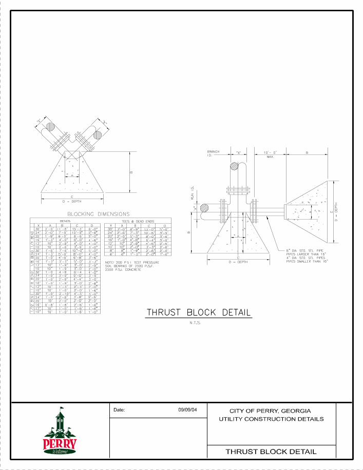
11. Thrust Blocking: Ready-mixed concrete having compressive strength of not
less than 2,500 psi shall be used as a cradle or thrust blocking where shown
on the plans or where directed by the Engineer. Bends exceeding 11 ¼
degrees, crosses with one opening plugged and all tees shall be backed with
concrete as a thrust block. Blocking shall be placed between solid ground and
the fitting to be anchored; the area of bearing on the pipe and on ground in each
instance shall be that shown on the plans. The blocking shall be so placed that
the pipe fitting joints will be accessible for repair.
12. Detection Tape: Plastic marking tape shall be installed over all water pipe.
Tape shall be blue in color and at least two inches (2”) wide and shall bear the
printed identification “Caution: Buried Water Line Below”. Marking tape shall
be buried one foot (1’-0”) below the ground surface above the water line.
13. Tracer Wire: All non-metallic water main pipe and water service tubing shall
have 12 gauge, insulated, copper wire placed on each pipe crown for detection
purposes.
14. Pressure and Leakage Tests
a. Pressure During Test: Immediately after the pipe has been laid and
backfilled, but prior to the placement of pavement, each valved section of
newly laid pipe shall be subjected to a leakage and pressure test. For any
section being tested, the pressure applied shall be such that at the
highest point in the section, the pressure shall be 150 psi or at least 50
psi above the normal operating pressure at this point, whichever is
greater. The test shall be witnessed by representatives of the City
and recorded on a circular chart recorder provided by the City.
b. Duration of Test: The duration of each pressure test shall be two (2)
hours.
c. Procedures: Each valved section of pipe shall be slowly filled with
water and the specified test pressure measured at the point of highest
elevation shall be supplied by means of a pump connected to the pipe in a
satisfactory manner. The pump, pipe connection and all necessary
apparatus, gauges and meters shall be furnished by the Contractor. The
Contractor shall furnish all necessary labor
PERRY, GEORGIA – WATER AND SANITARY SEWER SPECIFICATIONS 2-16

and assistance in conducting the tests. The Owner will furnish, through
connections made by the Contractor to existing mains, water for filling
the lines for making the test.
d. Expelling Air Before Tests: Before applying the specified test
pressure, all air shall be expelled from the pipe. To accomplish this,
taps shall be made, if necessary, at points of highest elevation and
afterwards tightly plugged.
e. Examination Under Pressure: At intervals during the test, the route of
the pipe line shall be inspected to locate any leaks or breaks. Any
cracked or defective joints, cracked or defective pipe, fittings or valves
discovered in consequence of this pressure test shall be removed and
replaced with sound material in the manner provided and the test shall be
repeated until satisfactory results are obtained.
f. Permissible Leakage: Leakage shall be defined as the quantity of water
that must be supplied into the newly laid pipe of any valved section
thereof, to maintain the specified leakage test pressure after the pipe has
been filled with water and the air in the pipeline has been expelled. No
installation will be accepted if leakage is greater than that determined by
the following formula:
L = SD(P)0.5
7400 Where: L is the allowable leakage in gallons per hour; S is the number
of joints in the length of pipeline tested; D is the nominal diameter of the
pipe in inches; and P is the average test pressure during the leakage test
in pounds per square inch (psi) gauge. Leakage values determined by the
above formula are to be found in the following tables:
ALLOWABLE LEAKAGE FOR PVC PLASTIC
WITH ELASTOMERIC JOINTS IN GALLONS PER HOUR
Nominal Pipe Size Average Pressure in Line - PSI
Inches 150 200
ALLOWABLE LEAKAGE PER 1,000 FEET
4" .33 .38 6" .50 .57 8" .66 .76 10" .83 .96 12" .99 1.15
PERRY, GEORGIA – WATER AND SANITARY SEWER SPECIFICATIONS 2-17
15. Backfilling, Cleaning Up and Maintaining Surfaces
a. Time of Backfilling: As soon as practicable after the completion of
laying and jointing of the pipe, the trench shall be backfilled and at no
time shall the completed backfilling of the trench be more than 300
feet behind the pipe laying.
b. Backfill Procedure at Pipe Zone: Select backfill material free from
rock fragments shall be deposited in the trench simultaneously on both
sides of the pope for the full width of the trench and to an elevation of six
inches (6”) above the top of the barrel of the pipe. The backfill material
shall be moistened, if necessary, tamped in thin (about four inch (4”)
layers and thoroughly compacted under and on each side of the pipe to
provide solid backing against the external surface of the pipe.
c. Backfill Procedure Above the Pipe Zone: Succeeding layers of backfill
may contain coarser materials and shall be compacted thoroughly to the
natural ground surface.
d. Procedure Where Settlement is Important: Where it is important that
the surface of the backfill be made safe for vehicular traffic at unpaved
street crossings and along existing unpaved streets, the entire backfill
shall be approved moist material, thoroughly compacted in six inch (6”)
layers by tamping and shall be brought to the required surface grade. All
backfill for trenches in these areas be compacted to 98% to the
Standard Proctor Maximum Density (ASTM D-698).
e. Procedure Where Settlement is Unimportant: Where pipe is laid
outside city streets or drives, hand tamping may be omitted in the layers
above six inches (6”) of the pipe crown. However, backfill shall be
compacted by other means to the surface and left neatly rounded over the
trench to a sufficient height to allow for the settlement to grade after
consolidation.
f. Compaction Test: Where settlement is important, the Contractor shall
furnish the City proof of compaction at pavement subgrade. Test shall be
at each street or drive crossing or at intervals not exceeding 400 feet in
continuous pavement areas. Contractor shall incur all costs for
compaction tests performed by a testing laboratory selected by the
Contractor and approved by the City.
PERRY, GEORGIA – WATER AND SANITARY SEWER SPECIFICATIONS 2-18

g. Deficiency of Backfill by Whom Supplied: Any deficiency in the
quantity of material for backfilling the trenches or for filling depressions
caused by settlement shall be supplied by the Contractor.
h. Restoration of Surfaces: The Contractor shall replace all curbing,
sidewalks, gutters, shrubbery, fences, sod, grass and other surfaces
disturbed to a condition equal to that before the work began,
furnishing all labor and materials incidental thereto and complete
the work in a manner satisfactory to the Engineer. Replacement of
street base and surface removed to permit installation of pipe lines shall
be provided for elsewhere in these specifications.
i. Backfill Under Paved Streets: Backfill under paved streets shall be
thoroughly compacted and as shown on the detailed drawings.
j. Surplus Earth: Surplus excavated materials from trenches in streets or
at railroad crossings shall be disposed of by the Contractor at his expense
and in a manner satisfactory to the City.
k. Cleaning Up: Surplus pipe line materials, tools, surplus excavated
materials, rubbish and temporary structures shall be removed by the
Contractor and the construction site shall be left clean to the satisfaction
of the Engineer. The line shall be cleaned up immediately after
satisfactory pressure tests have been made.
l. Maintenance of Surfaces: Following the certification of completion by
the Engineer, the Contractor shall maintain the surface of the unpaved
trenches, adjacent curbs, sidewalks, gutters and other surfaces disturbed
for a period of three (3) months thereafter.
All materials and labor required for the maintenance of the trenches and
adjacent structures shall be supplied by the Contractor and the work shall
be done in a manner satisfactory to the Engineer.
16. Disinfection of Mains: Disinfection and flushing of water mains shall be done
in accordance with AWWA C651 “Standard for Disinfecting Water Mains”. The
Contractor shall disinfect all new mains, furnishing all labor, equipment and
material necessary for the complete disinfection of the mains as hereinafter
provided. Mains shall be disinfected by the application of a chlorinating agent
into the water used for the initial filling of the mains. The chlorinating agent
may be chlorine gas-water mixture,
PERRY, GEORGIA – WATER AND SANITARY SEWER SPECIFICATIONS 2-19

calcium hypochlorite in water, or chlorinated lime of known chlorine content in
water and shall be fed through a suitable solution feed device. The chlorinating
agent shall be applied at or near the beginning point from which the main is
being filled and shall be injected into the main through a corporation cock tapped
into the horizontal exit of the newly laid main. The water being used to fill the
line shall be controlled to flow into the section to be sterilized very slowly and
the rate of application of the chlorinating agent shall be in such proportion to the
rate of the water entering the pipe that the chlorine dose applied to the water
shall be at least 50-ppm. The chlorine treated water shall be retained in the new
main at least 24 hours and a 10-ppm of residual chlorine shall remain after the 24
hour period. Following chlorination all treated water shall be flushed from the
mains until replacement water shall have a chlorine content of not more than 0.1-
ppm in excess of the residual in water from the supplying main and in any event
not less than 0.2-ppm. Samples of the water shall be taken by City of Perry
representatives and delivered to a state approved lab for bacteriological analysis.
The Contractor shall contact the City of Perry 48 hours prior to sampling
time. Should the analysis show contamination, the system shall be re-
chlorinated and further samples taken and submitted for analysis until no
contamination is indicated.
2.10 BORING
Furnish and install steel casing pipe by jacking and boring through whatever material may be
encountered. Construction shall be as described in Department of Transportation State of
Georgia Standard Specification Section 615.
A. General: Where groundwater is encountered, operate well points or drainage systems
in the vicinity of the casing to prevent the accumulation of flood water in the casing and
to maintain the groundwater table below the casing invert.
B. Pipe Casing: Furnish all material and equipment and perform all labor required to
install steel pipe casing at locations indicated on the drawings and as specified.
1. Boring: The steel casing pipe shall be Schedule 30 steel pipe manufactured
from steel conforming to ASTM A-139, Grade B. Size and thickness is as
follows:
PERRY, GEORGIA – WATER AND SANITARY SEWER SPECIFICATIONS 2-20
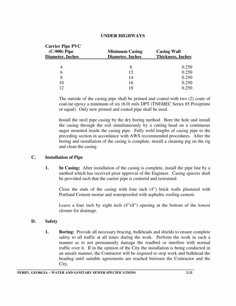
UNDER HIGHWAYS
Carrier Pipe PVC
(C-900) Pipe Minimum Casing Casing Wall Diameter, Inches Diameter, Inches Thickness, Inches
4 8 0.250 6 12 0.250 8 14 0.250 10 16 0.250 12 18 0.250
The outside of the casing pipe shall be primed and coated with two (2) coats of
coal-tar epoxy a minimum of six (6.0) mils DPT (TNEMEC Series 65 Poxiprime
or equal). Only new primed and coated pipe shall be used.
Install the steel pipe casing by the dry boring method. Bore the hole and install
the casing through the soil simultaneously by a cutting head on a continuous
auger mounted inside the casing pipe. Fully weld lengths of casing pipe to the
preceding section in accordance with AWS recommended procedures. After the
boring and installation of the casing is complete, install a cleaning pig on the rig
and clean the casing.
C. Installation of Pipe
1. In Casing: After installation of the casing is complete, install the pipe line by a
method which has received prior approval of the Engineer. Casing spacers shall
be provided such that the carrier pipe is centered and restrained.
Close the ends of the casing with four inch (4”) brick walls plastered with
Portland Cement mortar and waterproofed with asphaltic roofing cement.
Leave a four inch by eight inch (4”x8”) opening at the bottom of the lowest
closure for drainage.
D. Safety
1. Boring: Provide all necessary bracing, bulkheads and shields to ensure complete
safety to all traffic at all times during the work. Perform the work in such a
manner as to not permanently damage the roadbed or interfere with normal
traffic over it. If in the opinion of the City the installation is being conducted in
an unsafe manner, the Contractor will be required to stop work and bulkhead the
heading until suitable agreements are reached between the Contractor and the
City.
PERRY, GEORGIA – WATER AND SANITARY SEWER SPECIFICATIONS 2-21

2.11 STREAM AND DITCH CROSSING
At all points where banks of streams of drainage ditches are disturbed by excavation or where
natural vegetation is removed, carefully compact backfill and place rip-rap to prevent
subsequent settlement and erosion.
This requirement applies equally to construction along side a stream or drainage ditch as well as
crossing a stream or drainage ditch. Place rip-rap a distance of not less than ten feet (10’)
upstream and ten feet (10’) downstream from any disturbed area. Extend rip-rap from one foot
(1’) below streambed to top of bank. Place to conform with the natural slope of the stream
bank.
A. Stone Rip-Rap: Use sound, tough, durable stones resistant to the action of air and
water. Slabby or shaley pieces will not be acceptable. Specific gravity shall be two
(2.0) or higher.
Minimum weight of individual stones shall be fifty (50) pounds. The maximum
allowable dimension for an individual stone is 24 inches. The minimum allowable
dimension for an individual stone is six inches (6”). At least fifty percent (50%) of the
stones shall have a minimum dimension of twelve inches (12”).
Embed stone rip-rap by and so as to form a compact layer at least twelve inches (12”)
thick. Place rip-rap in such a way that the smaller stones are not segregated but evenly
distributed. Place chinking stones in the crevices between the larger stones so that a
dense, well graded mass is produced.
PERRY, GEORGIA – WATER AND SANITARY SEWER SPECIFICATIONS 2-22
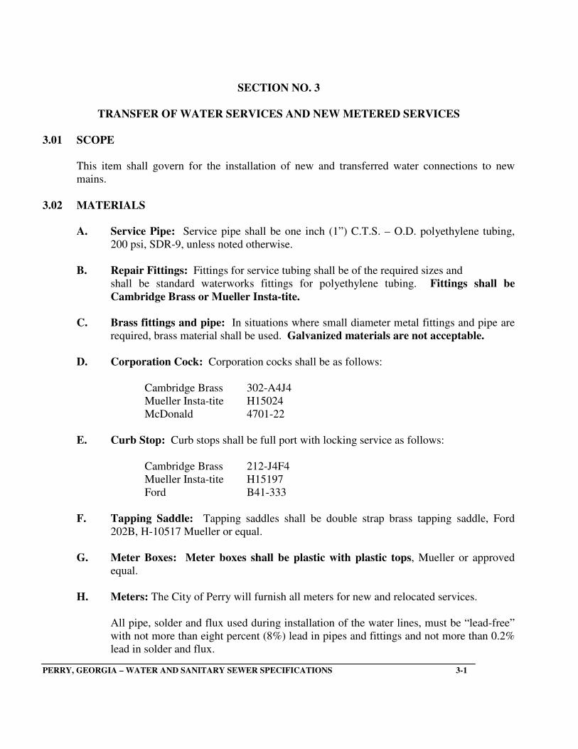
SECTION NO. 3
TRANSFER OF WATER SERVICES AND NEW METERED SERVICES
3.01 SCOPE
This item shall govern for the installation of new and transferred water connections to new
mains.
3.02 MATERIALS
A. Service Pipe: Service pipe shall be one inch (1”) C.T.S. – O.D. polyethylene tubing,
200 psi, SDR-9, unless noted otherwise.
B. Repair Fittings: Fittings for service tubing shall be of the required sizes and
shall be standard waterworks fittings for polyethylene tubing. Fittings shall be
Cambridge Brass or Mueller Insta-tite.
C. Brass fittings and pipe: In situations where small diameter metal fittings and pipe are
required, brass material shall be used. Galvanized materials are not acceptable.
D. Corporation Cock: Corporation cocks shall be as follows:
Cambridge Brass 302-A4J4
Mueller Insta-tite H15024
McDonald 4701-22
E. Curb Stop: Curb stops shall be full port with locking service as follows:
Cambridge Brass 212-J4F4
Mueller Insta-tite H15197
Ford B41-333
F. Tapping Saddle: Tapping saddles shall be double strap brass tapping saddle, Ford
202B, H-10517 Mueller or equal.
G. Meter Boxes: Meter boxes shall be plastic with plastic tops, Mueller or approved
equal.
H. Meters: The City of Perry will furnish all meters for new and relocated services.
All pipe, solder and flux used during installation of the water lines, must be “lead-free”
with not more than eight percent (8%) lead in pipes and fittings and not more than 0.2%
lead in solder and flux.
PERRY, GEORGIA – WATER AND SANITARY SEWER SPECIFICATIONS 3-1
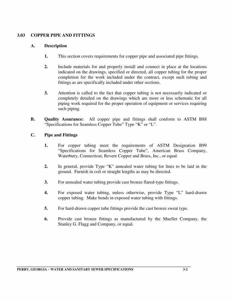
3.03 COPPER PIPE AND FITTINGS
A. Description
1. This section covers requirements for copper pipe and associated pipe fittings.
2. Include materials for and properly install and connect in place at the locations
indicated on the drawings, specified or directed, all copper tubing for the proper
completion for the work included under the contract, except such tubing and
fittings as are specifically included under other sections.
3. Attention is called to the fact that copper tubing is not necessarily indicated or
completely detailed on the drawings which are more or less schematic for all
piping work required for the proper operation of equipment or services requiring
such piping.
B. Quality Assurance: All copper pipe and fittings shall conform to ASTM B88
“Specifications for Seamless Copper Tube” Type “K” or “L”.
C. Pipe and Fittings
1. For copper tubing meet the requirements of ASTM Designation B99
“Specifications for Seamless Copper Tube”, American Brass Company,
Waterbury, Connecticut, Revere Copper and Brass, Inc., or equal.
2. In general, provide Type “K” annealed water tubing for lines to be laid in the
ground. Furnish in coil or straight lengths as may be directed.
3. For annealed water tubing provide cast bronze flared-type fittings.
4. For exposed water tubing, unless otherwise, provide Type “L” hard-drawn
copper tubing. Make bends in exposed water tubing with fittings.
5. For hard-drawn copper tube fittings provide the cast bronze sweat type.
6. Provide cast bronze fittings as manufactured by the Mueller Company, the
Stanley G. Flagg and Company, or equal.
PERRY, GEORGIA – WATER AND SANITARY SEWER SPECIFICATIONS 3-2

D. Installation
1. Carefully place tubing to proper lines and grades and run true and plumb to
surfaces in an approved workmanlike manner.
2. Cut annealed “Type K” water copper tube square, preferably with a hacksaw,
ream ends and flare using suitable tools. Use bending tools for making ends.
3. Assemble hard drawn “Type L” copper using solder and flux as recommended
by the manufacturer of the tubing. Cut tubing square, preferably with hacksaw,
then ream ends and polish both fitting and tube with steel wool before fluxing.
Properly heat taking care not to over heat. After running solder, wipe joint clean.
Install copper tubing only in accordance with the manufacturer’s instructions.
4. Install pipe in such a manner and at such times as will require no cutting and
repairing of work in place. In case such cut and repair is necessary, do only with
the permission of the Engineer. Perform cutting and repairing by the mechanics
who originally installed the work. Make repairs match the original condition.
Follow the pipe practices in the installation of copper tubing and fittings, insofar
as applicable, as follows:
a. Where copper tubing is connected to ferrous piping or equipment with
ferrous fittings, provide approved insulating bushings to be used.
b. Where copper lines pass through exterior wall, carry “Type K” through a
pipe sleeve provided for this purpose and connect “Type L” inside the
building by use of adapter fittings.
3.04 CONSTRUCTION METHODS
All service connections shall be made before the new main has been tested and sterilized.
Installation of corporation cocks on pipe shall be made with the use of a service clamp of the
proper size to fit the main. Water taps shall be ten feet (10’) apart minimum.
A. Transfer of an existing water service shall consist of digging down to the existing main,
closing the corporation cock, cutting/plugging the existing service, tapping the new
main, installing a new corporation cock, running new service pipe to the existing or
relocated meter, tying the new pipe into the existing meter and backfilling all ditches.
B. New services shall consist of tapping the new main, installation of corporation cock,
installation of service pipe to meter location and installation of curb stop.
PERRY, GEORGIA – WATER AND SANITARY SEWER SPECIFICATIONS 3-3

C. Location of Services: Services shall be located in the center of proposed
residential lots. In other cases the intent is to avoid a location that places the
service under a proposed driveway or other permanent structure. Ten foot (10’)
separation is required between the water service and sanitary sewer service.
D Marking for Future Reference: New water service lines shall be marked for future
reference with six foot (6’) 4”x4” pressure-treated posts installed plumb. Four feet
(4’) of the post shall be above finish grade and painted “blue”.
E. All one inch (1”) water service lines under pavement shall be installed in a two inch
(2”) diameter Schedule 40 PVC casing. The casing shall extend beyond the
pavement edge or back of curb two feet (2’) on each end.
F. Where required, the Contractor shall relocate existing meter and box.
G. The Contractor shall free bore or open cut paved driveways, sidewalks and curbing for
the placement of services; however, the Contractor must bore services under all city
streets and federal or state highways.
H. Where services are to be transferred to the new main and the existing main lies within a
paved street, a new water service shall be run from the new main to the existing meter
box and terminate with a curb stop. The existing service pipe shall then be abandoned
by shutting it off at its source.
I. Whenever sanitary sewers cross existing or proposed water mains, a minimum
vertical separation of eighteen inches (18”) must be maintained between the two (2)
pipes (measured edge to edge).
PERRY, GEORGIA – WATER AND SANITARY SEWER SPECIFICATIONS 3-4
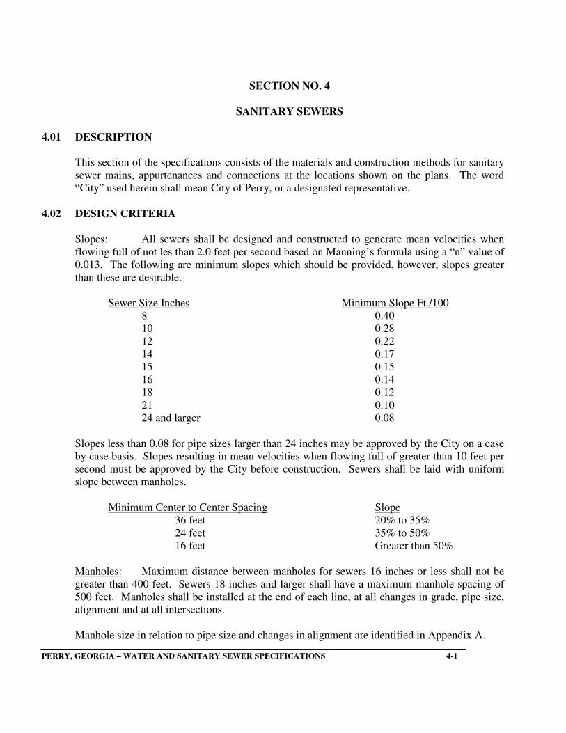
SECTION NO. 4
SANITARY SEWERS
4.01 DESCRIPTION
This section of the specifications consists of the materials and construction methods for sanitary
sewer mains, appurtenances and connections at the locations shown on the plans. The word
“City” used herein shall mean City of Perry, or a designated representative.
4.02 DESIGN CRITERIA
Slopes: All sewers shall be designed and constructed to generate mean velocities when
flowing full of not les than 2.0 feet per second based on Manning’s formula using a “n” value of
0.013. The following are minimum slopes which should be provided, however, slopes greater
than these are desirable.
Sewer Size Inches Minimum Slope Ft./100
8 0.40
10 0.28
12 0.22
14 0.17
15 0.15
16 0.14
18 0.12
21 0.10
24 and larger 0.08
Slopes less than 0.08 for pipe sizes larger than 24 inches may be approved by the City on a case
by case basis. Slopes resulting in mean velocities when flowing full of greater than 10 feet per
second must be approved by the City before construction. Sewers shall be laid with uniform
slope between manholes.
Minimum Center to Center Spacing Slope
36 feet 20% to 35%
24 feet 35% to 50%
16 feet Greater than 50%
Manholes: Maximum distance between manholes for sewers 16 inches or less shall not be
greater than 400 feet. Sewers 18 inches and larger shall have a maximum manhole spacing of
500 feet. Manholes shall be installed at the end of each line, at all changes in grade, pipe size,
alignment and at all intersections.
Manhole size in relation to pipe size and changes in alignment are identified in Appendix A.
PERRY, GEORGIA – WATER AND SANITARY SEWER SPECIFICATIONS 4-1

4.03 CONSTRUCTION DRAWINGS
The term “construction drawings” shall mean drawings, prints, descriptive literature, test
reports, samples, calculations, schedules, material lists, information and items of similar
meaning.
A. Submittals Required: The Contractor shall furnish to the City of Perry, for review in
accordance with the procedure outlined below, drawings and descriptive literature for all
manufactured or fabricated products. Additional information, such as special drawings,
schedules, calculations and tests, shall be provided as specifically requested by the City.
B. Contractor’s Review: The Contractor shall review and check drawings and submittals.
He shall indicate his review by initials and date. The Contractor shall furnish the City
with a minimum of three (3) copies of all submittals. A transmittal form shall
accompany each submittal or group of submittals.
C. Review: All submittals will be reviewed, stamped and dated by the City before they are
returned to the Contractor.
One (1) copy of reviewed submittals will be returned to the Contractor and the
remaining copies retained by the City.
Submittals requiring minor corrections will be so noted. Drawings must be resubmitted
for review prior to installation or use of products.
D. Drawings for Construction: The Contractor shall maintain at the job site a
complete set of construction drawings. The Contractor shall maintain throughout
the project a set of “As-Built” mark-up plans indicating the locations of
manholes, taps, etc., and changes to the original plans with field measurements.
At project completion, the developer/owner is to provide the City of Perry a
survey of the sanitary sewer system prepared by a land surveyor licensed by
the State of Georgia. The survey shall include the elevation(s) of the
invert(s)of each manhole, the elevation of the top of each manhole, the
location of each manhole and the length of each pipeline between manholes.
The survey shall be tied to the State Plane Coordinate System. This
information is to be incorporated into the final as-built drawings prepared by the
design engineer. The developer/owner is to provide the City of Perry with
one full printed set of as-built construction plans and an electronic copy of the as-
built construction plans on CD-ROM in the AutoCad 14 format or a later version.
The printed set and CD-ROM are to be provided upon completion of the project
and before final acceptance. (Note: Dimension each sewer service from the
downstream manhole along the centerline of the sewer main).
PERRY, GEORGIA – WATER AND SANITARY SEWER SPECIFICATIONS 4-2

4.04 MATERIALS
A. Pipe: Sewer pipe shall conform to the requirements of the specifications as follows:
1. General: All pipe shall be subject to inspection at the pipe plant, trench or other
point of delivery for the purpose of culling and rejecting pipe which does not
conform to the requirements of these specifications. The manufacturer of the
pipe shall submit evidence of having consistently produced both pipe and joints
of satisfactory quality and performance results in service over a period of at least
two (2) years.
2. Polyvinyl Chloride (PVC) – pipe shall conform to the following specifications:
Polyvinyl chloride (PVC) plastic sewer pipe shall be unplasturized polyvinyl
chloride with integral wall bell and spigot joints with a rubber ring gasket. Pipe
and fittings shall meet all the requirements of ASTM D-3034 SDR 35 or use as a
gravity sewer main conduit. Provisions must be made for contraction and
expansion at each joint with a rubber ring. The bell shall consist of an integral
wall section stiffened with two (2) PVC retainer rings which securely lock the
solid section rubber ring into position or shall be equal to the confined rubber
gasket joint that meets the requirements of AWWA C-302, ASTM D-443 and
ASTM D-3212. Standard lengths shall not exceed twenty feet (20’). Sizes and
dimensions shall be as shown in the table as follows:
Outside Diameter Minimum Wall
Nominal Size Average Tolerance Thickness SDR-
35
4”
6”
8”
10”
12”
15”
4.215
6.275
8.400
10.500
12.500
15.300
±0.007
±0.009
±0.010
±0.013
±0.016
±0.210
0.120
0.180
0.240
0.300
0.360
0.437
PERRY, GEORGIA – WATER AND SANITARY SEWER SPECIFICATIONS 4-3

Minimum “pipe stiffness” (F/Y) at 5% deflection shall be 46 for all sizes when
tested in accordance with ASTM Designation D-2412. External loading
properties of plastic pipe by Parallel Plate loading.
Installation of PVC sewer pipe shall be in accordance with the provisions of
ASTM-2321, “Underground Installation of Flexible Thermoplastic Sewer Pipe”
with additional bedding as required in these specifications.
a. Detection Tape: Plastic marking tape shall be installed over all
sewer pipe. Tape shall be green in color and at least two inches (2”)
wide and shall bear the printed identification “Caution: Buried
Sewer Line Below”. Marking tape shall be buried one foot (1’-0”)
below the ground surface above the sewer line.
b. Tracer Wire: All non-metallic sewer main pipe and sewer service
pipe shall have 12 gauge, insulated, copper wire placed on each pipe
crown for detection purposes.
3. Ductile Iron Pipe (DIP): Ductile iron pipe shall conform to AWWA C151 and
shall be a minimum of Pressure Class 350. Sizes will be as shown on the
drawings. Pipe and fittings shall be cement lined in accordance with AWWA
C104. Joints shall be push-on type for pipe and standard mechanical or flanged
joints for fittings unless otherwise noted. Push-on and mechanical joints shall
conform to AWWA C111. Restrained joint pipe (RJP) shall be either the bolted
joint type or modified push-on type with joint restraint using ductile iron
components. Restrained joint pipe where required shall be American, U.S. Pipe,
McWane or equal.
a. Ductile iron pipe shall be used when the cover over the pipe is less
than three feet, when the sanitary sewer line crosses under a storm
drain line and the vertical separation between the two lines is less
than 3 feet, and when the depth of cover over the pipe is greater than
25 feet.
b. Detection Tape: Plastic marking tape shall be installed over all
sewer pipe. Tape shall be green in color and at least two inches (2”)
wide and shall bear the printed identification “Caution: Buried
Sewer Line Below”. Marking tape shall be buried one foot (1’-0”)
below the ground surface above the sewer line.
PERRY, GEORGIA – WATER AND SANITARY SEWER SPECIFICATIONS 4-4

B. Pipe Joints
1. Polyvinyl Chloride (PVC): Flexible gasketed joints for PVC sewer main pipe
shall be compression type conforming to ASTM D-3212. The gasket shall
comply with ASTM F-477. Joints shall be tested for tightness as follows:
Assemble two (2) sections of pipe in accordance with the manufacturer’s
recommendations. Subject the joints to an internal hydrostatic pressure of 25 psi
for one (1) hour. Consider any leakage a failure of the test requirements.
2. Ductile Iron Sewer Pipe: Flexible rubber gasket joint Type II, or mechanical
joint Type III, conforming to ASA Specifications A21.11.
3. Transition Joints: The transition between sewer pipes of different materials
shall be made in accordance with the detail for concrete collars. The transition
between clay pipe and cast iron pipe shall be by clay double bell cast iron
adapters with compression joints conforming to ASTM Specifications C-425
(latest). Adapters between iron pipe and pipe of materials other than clay will be
accepted upon approval of the City. In most cases where special adapters are not
available or not approved by the City, concrete collars will be used.
C. Pipeline Casing Spacers: Each pipeline casing spacer shall be two (2) piece 14
gauge T-304 stainless steel with corrosion resistant clamps for carrier pipe. The runners
shall be ultra high molecular weight polymer to resist abrasion and sliding wear and
configured to center the carrier pipe in the casing pipe with adequate support. Spacing
shall be as recommended by the manufacturer. Spacers shall be Cascade or an approved
equal.
4.05 CONSTRUCTION METHODS
A. General: The Contractor shall excavate the trenches and manholes to the required
dimensions; excavate the bell holes; construct and maintain all bridges required for
traffic control; sheet, brace and support the adjoining ground or structures where
necessary; replace all damaged water services, drains, sewers or other structures; backfill
trenches; restore the roadway surfaces; remove surplus excavated materials; clean the
site of the work and maintain the street or other surfaces of the trenches.
PERRY, GEORGIA – WATER AND SANITARY SEWER SPECIFICATIONS 4-5

B. Manholes shall be constructed at the locations shown on the plans. Manholes shall be
the type as specified in Section 5.
C. Where inlet leads and main or lateral pipe sewers enter a manhole, such pipes shall be
cut-off flush with the inside of the manhole and any irregularities shall be pointed up
with mortar.
D. The inverts of the sewer lines entering manholes at or near the flow line elevation of the
manhole shall be shaped and routed across the floor of the manhole using concrete and
mortar to obtain the proper contour.
E. Where the sewers enter a new manhole, an appropriate seal (neoprene boot) shall be
used to positively seal against infiltration or exfiltration.
F. Where sewers enter existing manholes, the wall of the manhole shall be core drilled
and an appropriate seal (boot) shall be used as shown on the drawings to positively
seal against infiltration or exfiltration.
G. Location of Services: Services shall be located in the center of proposed
residential lots. In other cases the intent is to avoid a location that places the
service under a proposed driveway or other permanent structure. Ten foot (10’)
separation is required between the water service and sanitary sewer service.
H. Location of Service Fittings: All tees and other fittings shall be placed at the points
indicated on the plans. Tee branches shall be laid to correspond with the sewers and
house service lines entering them. When service lines are installed and short runs of
service lines are constructed to a point for future extension, they shall be closed with
caps made for the same pipe material and sealed with like joint material as used for
jointing bell and sockets of regular sewer pipe.
Each service connection shall be referenced on the as-built drawings with a
dimension measured from the downstream manhole.
I. Inspection
1. Of Materials at Delivery Point: During the process of unloading all pipe and
accessories, each shall be inspected by the Contractor for loss or damage in
transit.
2. Field Inspection: All pipe and accessories shall be laid and jointed in the
manner herein specified in the presence of the City’s authorized inspector.
3. Disposition of Defective Material: All material found during the process of the
work to have cracks, flaws or other defects will be rejected and the Contractor
shall promptly remove such material from the job site.
PERRY, GEORGIA – WATER AND SANITARY SEWER SPECIFICATIONS 4-6

J. Contractor’s Responsibility for Materials: The Contractor shall be responsible for all
material furnished to him and he shall replace at his own expense all such materials that
have become damaged in handling after delivery. The Contractor shall be responsible
for the safe storage of materials furnished by or to him and accepted by him, intended
for the work until it has been incorporated in the completed project.
K. Alignment and Grade
1. General: All pipe shall be laid and maintained in the required lines and grades
with wyes or tees at the required locations and with joints centered and spigots
home. The Contractor shall at his own expense, furnish and place in position all
necessary stakes and batter boards for locating the work. The Contractor must
also furnish at his own expense, good spun twilled lines or wire for use in giving
lines and grades and the necessary plummets and grade poles. The laser beam
method may be employed.
2. Protecting Underground and Surface Structures: Temporary support,
adequate protection and maintenance of all underground and surface utility
structures, water services, gas services, poles, guy wires, drains, sewers and other
obstructions encountered in the progress of the work shall be furnished by the
Contractor at his own expense.
a. Protection of Water Supplies
(1) Water Supply Interconnections: There shall be no physical
connection between a public or private potable water supply
system and a sewer, or an appurtenance thereto, which would
permit the passage of any sewage or polluted water into the
potable supply.
(2) Relation to Water Works Structures: While no general
statement can be made to cover all conditions, it is generally
recognized that sewers shall meet the requirements of the
approving agency with respect to minimum distances from public
water supply wells or other water supply sources and structures.
PERRY, GEORGIA – WATER AND SANITARY SEWER SPECIFICATIONS 4-7

(3) Relation to Water Mains
(a) Horizontal Separation: Whenever possible, sewers
should be laid at least ten feet (10’), horizontally, from
an existing or proposed water main. Should local
conditions prevent a lateral separation of ten feet (10’), a
sewer may be laid closer than ten feet (10’) to a water
main if:
(1) It is laid in a separate trench.
(2) It is laid in the same trench with the water mains
located at one side on a bench of undisturbed earth.
(3) In either case, the elevation of the crown of the
sewer is at least eighteen inches (18”) below the
invert of the water main.
(b) Vertical Separation: Whenever sewers must cross under
water mains, the sewer laid at such an elevation that the
top of the sewer is at least eighteen inches (18”) below the
bottom of the water main.
When the elevation of the sewer cannot be buried to
meet the above requirement, the water main shall be
relocated to provide this separation or reconstructed
with slip-on or mechanical joint ductile iron pipe, or
pre-stressed concrete cylinder pipe for a distance of ten
feet (10’) on each side of the sewer. One (1) full length
of water main should be centered over the sewer so
that both joints will be as far from the sewer as
possible.
3. Deviations Occasioned by Other Utility Structures: Wherever existing utility
structures or branch connections leading to main sewers or storm sewers, or
other conduits, ducts, pipes or structures present, obstructions to the grade and
alignment of the pipe, they shall be permanently supported, removed, relocated
or reconstructed by the Contractor through cooperation with the Owner of the
utility structures or obstructions. Wherever necessary to move service poles, guy
wires, pipe lines or other obstructions, the Contractor shall notify and cooperate
with the utility owner. In those instances where their location or reconstruction
is impracticable, a deviation from line and grade will be ordered and the change
shall be made in the manner directed.
PERRY, GEORGIA – WATER AND SANITARY SEWER SPECIFICATIONS 4-8
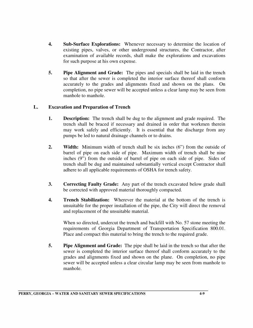
4. Sub-Surface Explorations: Whenever necessary to determine the location of
existing pipes, valves, or other underground structures, the Contractor, after
examination of available records, shall make the explorations and excavations
for such purpose at his own expense.
5. Pipe Alignment and Grade: The pipes and specials shall be laid in the trench
so that after the sewer is completed the interior surface thereof shall conform
accurately to the grades and alignments fixed and shown on the plans. On
completion, no pipe sewer will be accepted unless a clear lamp may be seen from
manhole to manhole.
L. Excavation and Preparation of Trench
1. Description: The trench shall be dug to the alignment and grade required. The
trench shall be braced if necessary and drained in order that workmen therein
may work safely and efficiently. It is essential that the discharge from any
pumps be led to natural drainage channels or to drains.
2. Width: Minimum width of trench shall be six inches (6”) from the outside of
barrel of pipe on each side of pipe. Maximum width of trench shall be nine
inches (9”) from the outside of barrel of pipe on each side of pipe. Sides of
trench shall be dug and maintained substantially vertical except Contractor shall
adhere to all applicable requirements of OSHA for trench safety.
3. Correcting Faulty Grade: Any part of the trench excavated below grade shall
be corrected with approved material thoroughly compacted.
4. Trench Stabilization: Wherever the material at the bottom of the trench is
unsuitable for the proper installation of the pipe, the City will direct the removal
and replacement of the unsuitable material.
When so directed, undercut the trench and backfill with No. 57 stone meeting the
requirements of Georgia Department of Transportation Specification 800.01.
Place and compact this material to bring the trench to the required grade.
5. Pipe Alignment and Grade: The pipe shall be laid in the trench so that after the
sewer is completed the interior surface thereof shall conform accurately to the
grades and alignments fixed and shown on the plane. On completion, no pipe
sewer will be accepted unless a clear circular lamp may be seen from manhole to
manhole.
PERRY, GEORGIA – WATER AND SANITARY SEWER SPECIFICATIONS 4-9
6. Rock Excavation
a. Definition of Rock: Any material which cannot be excavated with a
backhoe having a bucket curling force rated at not less that 18,300
pounds (Caterpillar Model 215 or equal) and occupying an original
volume of at least one-half (1/2) cubic yard.
b. Excavation: Where rock is encountered in trenches, excavate to the
minimum depth which will provide clearance below the pipe barrel of
four inches (4”) plus required bedding depth for pipe and manholes.
Remove boulders and stones to provide a minimum of six inches (6”)
clearance between the rock and any part of the pipe of manhole.
c. Blasting: Provide experienced workmen to perform blasting. Conduct
blasting operations in accordance with all existing ordinances and
regulations. Protect all structures from the effects of the blast. Repair
any resulting damage.
If the Contractor persistently uses excessive blasting charges or blasts in
an unsafe or improper manner, the City may direct the Contractor to
employ an independent blasting consultant to supervise the preparation
for each blast and approve the quantity of each charge.
d. Removal or Rock: Do not use excavated rock as backfill material.
Dispose of rock which is surplus or not suitable for use as rip-rap.
7. Haunching of Sewer: Haunch pipelines in accordance with detail drawings and
the following specifications. Haunching will be required for all gravity sewers.
Haunching material shall be No. 57 stone.
8. Bedding of Sewer: Bed pipelines in accordance with the following
specifications:
a. Bedding Materials
(1) Ductile Iron Sewer: All bedding materials shall be crushed stone
unless shown or specified otherwise. Crushed stone bedding
material shall meet the requirements of Georgia Department of
Transportation Specification 800.01 for No. 57 stone.
PERRY, GEORGIA – WATER AND SANITARY SEWER SPECIFICATIONS 4-10
(2) PVC Sewer: All bedding materials shall be crushed stone
bedding material shall meet the requirements of Georgia
Department of Transportation Specification 800.01 for No. 57
stone.
(3) Sewer Laterals: The bedding requirement for laterals from the
sewer to the edge of the road right-of-way or easement shall be
the same as applicable to the main sewer and as explained above
in (2).
(4) Manholes: All bedding materials shall be crushed stone unless
shown or specified otherwise. Crushed stone bedding material
shall meet the requirements of Georgia Department of
Transportation Specification 800.01 for No. 57 stone.
b. General: Compact stone bedding material by tamping or slicing with a
flatblade shovel. Prepare the trench bottom to support the pipe uniformly
throughout its length. Provide bell holes to relieve pipe bells of all load.
If the trench is excavated to excessive width or depth, provide the next
better class of bedding. In rock trenches, bed pipe in at least six inches
(6”) of bedding material.
(1) PVC Pipe: Excavate the bottom of the trench flat at a minimum
depth shown on the drawings below the bottom of the pipe barrel.
Place the compacted bedding and haunching material to the
proper grade. Bedding and haunching shall then be carefully
placed by hand and compacted to provide full support under
and on each side of the pipe to six inches (6”) above the top of
the barrel.
(2) Sewer Laterals: The bedding requirement for the laterals from
the main sewer to the edge of the road right-of-way or easement
shall be the same as applicable to the main sewer and as
explained above in (2).
(3) Manholes: Excavate to a minimum of eight inches (8”) below
the planned elevation of the base of the manhole. Place and
compact stone bedding material to the required grade before
constructing the manhole.
PERRY, GEORGIA – WATER AND SANITARY SEWER SPECIFICATIONS 4-11

(5) Compaction: Bedding under pipe and manholes shall be
compacted to a minimum of 85 percent of the maximum dry
density as determined by the Standard Proctor Compaction
Test, ASTM D-698.
9. Care of Surface Material for Reuse: If local conditions permit their reuse, all
surface materials suitable for reuse in restoring the surface shall be kept separate
from the general excavation material.
10. Manner of Piling Excavated Materials: All excavated materials shall be piled
so that it will not endanger the work and so that it will avoid obstructing roads
and driveways. Drainage channels shall be kept clear or other satisfactory
provisions made for drainage.
11. Trenching by Machine or by Hand: The use of trench digging machinery will
be permitted except in places where operation of same will cause damage to
existing structures above or below the ground; in which case hand methods shall
be employed.
M. Pipe Handling
1. Manner of Handling Pipe: Proper implements, tools and facilities shall be
provided and used by the Contractor for convenient prosecution of the work. All
pipe shall be carefully lowered into the trench piece by piece by means of
suitable tools or equipment in such a manner as to prevent damage to pipe.
Under no circumstances shall pipe be dropped or dumped into the trench.
2. Inspection: Before lowering and while suspended, the pipe shall be inspected
for defects. Any defective, damaged or unsound pipe shall be rejected.
3. Pipe Kept Clean: All foreign matter or dirt shall be removed from the pipe and
it shall be kept clean by approved means during and after laying.
4. Laying of Pipe: The laying of pipes in finished trenches shall commence at the
lowest point so that spigot ends point in the direction of flow. All pipe shall be
laid with ends abutting the true to line and grade. They shall be fitted and
matched so that when laid in the work they will form a sewer with a smooth and
uniform invert. All possible care shall be taken when shoving the pipes together
so that the joints will not be unnecessarily large. Sockets and spigots shall be
carefully cleaned before pipes are jointed.
PERRY, GEORGIA – WATER AND SANITARY SEWER SPECIFICATIONS 4-12
5. Unsuitable Conditions for Laying Pipe: No pipe shall be laid in water or when
the trench conditions or weather is unsuitable for such work except in an
emergency.
6. Encasement and Blocking of Sewer Pipes: Where specifically indicated on the
plans, the Contractor shall encase of block sewer pipes in conformity with details
and type of concrete specified. Sewer lines to be encased shall be encased in
3,000 psi concrete a minimum of six inches (6”) on all sides of the pipe.
N. Backfilling Trenches
1. Time of Backfilling: As soon as practicable after the completion of laying and
jointing of the pipe, the trench shall be backfilled and at no time shall the
completed backfilled trench be more than 200 feet behind the pipe laying.
2. Backfill Procedure at Pipe Zone: Haunching material shall be deposited in the
trench simultaneously on both sides of the pipe for the full width of the trench to
an elevation as shown on the detail for type pipe selected. Initial backfill
material shall be moistened if necessary, tamped in thin six inch (6”) layers and
thoroughly compacted on each side of the pipe as shown on the Typical Sewer
Pipe Bedding Detail. Walking or working on the completed pipe line, except as
may be necessary in tamping or backfilling, will not be permitted until the trench
has been compacted or a height of at least two-and-one-half feet (2 ½’) over the
barrel of the pipe for PVC pipe and two feet (2’) over the barrel of the pipe for
ductile iron (DI) pipe.
3. Compaction Requirements: All backfill for trenches under paved or
roadway areas shall be compacted to 98 percent of the Standard Proctor
maximum density (ASTM D-698). Backfill for trenches other than under
pavement areas shall be compacted to 95 percent of the Standard Proctor
maximum density (ASTM D-698) to eighteen inches (18”) above the crown
of the pipe. The remainder shall be compacted to 93 percent of the Standard
Proctor maximum density (ASTM D-698).
The Contractor shall furnish the City proof of compaction at a point
eighteen inches (18”) above the crown of the sewer pipe at all pavement,
driveway or roadway crossings. Additional compaction tests are required at
each crossing eight inches (8”) below the surface of the pavement or on the
pavement subgrade before pavement placement. Contractor shall incur all
costs for compaction tests performed by a testing laboratory approved by the
City and selected by the Contractor.
PERRY, GEORGIA – WATER AND SANITARY SEWER SPECIFICATIONS 4-13

4. Rock and Rock Fragment Exclusion: No rock or rock fragments shall be used
in the backfill for at least eighteen inches (18”) above the top of the pipe and no
stone larger than eight inches (8”) in its greatest dimension shall be used in the
backfill.
5. Deficiency of Backfill: Any deficiency in the quantity of material for
backfilling the trenches or for filling depressions caused by settlement shall be
supplied by the Contractor.
O. Boring: Furnish and install steel casing pipe by jacking and boring through whatever
material may be encountered. Construction shall be as described in State of Georgia
Department of Transportation Standard Specification Section 615.
1. General: Where groundwater is encountered, operate well points or drainage
systems in the vicinity of the casing to prevent the accumulation of flood water
in the casing and to maintain the groundwater table below the casing invert.
2. Pipe Casing: Furnish all material and equipment and perform all labor required
to install steel pipe casing at locations indicated on the drawings and as specified.
a. Boring: The steel casing pipe shall be Schedule 30 steel pipe
manufactured from steel conforming to ASTM A-139, Grade B. Size and
thickness shall be as follows:
UNDER HIGHWAYS
Carrier Pipe PVC
Pipe Minimum Steel Casing Casing Wall Diameter, Inches Diameter, Inches Thickness, Inches
4 8 0.250 6 12 0.250 8 14 0.250 10 16 0.250 12 18 0.250
PERRY, GEORGIA – WATER AND SANITARY SEWER SPECIFICATIONS 4-14

UNDER RAILROADS
Pipe Casing Wall
Diameter, Inches Diameter, Inches Thickness, Inches
6 14 0.250 8 18 0.250 10 20 0.281 12 22 0.312
The outside of the casing pipe shall be primed and coated with two (2) coats of coal tar epoxy a minimum of six (6) mils DFT (TNEMEC Series 65 Poxiprime or equal). Only new primed and coated pipe shall be used.
Install the steel pipe casing by the dry boring method. Bore the hole and
install the casing through the soil simultaneously by a cutting head on a
continuous auger mounted inside the casing pipe. Fully weld lengths of
casing pipe to the preceding section in accordance with AWS
recommended procedures. After the boring and installation of the casing
is complete, install a cleaning pig on the rig and clean the casing.
3. Installation of Pipe
a. In Casing: After installation of the casing is complete, install the pipe
line by a method which has received prior approval of the engineer.
Casing spacers shall be provided such that the carrier pipe is centered and
restrained.
Close the ends of the casing with four inch (4”) brick walls, plastered
with Portland Cement mortar and waterproofed with asphaltic roofing
cement.
Leave a four inch by eight inch (4” x 8”) opening at the bottom of the
lowest closure for drainage.
4. Safety
a. Boring: Provide all necessary bracing, bulkheads and shields to ensure
complete safety to all traffic at all times during the work. Perform the
work in such a manner as to not permanently damage the roadbed or
interfere with normal traffic over it. If in the opinion of the City the
installation is being conducted in an unsafe manner, the Contractor will
be required to stop work and bulkhead the heading until suitable
agreements are reached between the Contractor and the City.
PERRY, GEORGIA – WATER AND SANITARY SEWER SPECIFICATIONS 4-15
P. Stream and Ditch Crossing: At all points where banks of streams or drainage
ditches are disturbed by excavation or where natural vegetation is removed, carefully
compact backfill and place rip rap to prevent subsequent settlement and erosion.
This requirement applies equally to construction alongside a stream or drainage ditch as
well as crossing stream or drainage ditch. Place rip rap a distance of not less than 10
feet upstream and 10 feet downstream from any disturbed area. Extend rip rap from 1
foot below streambed to top of bank. Place to conform with the natural slope of the
stream bank. The pipe material for stream and ditch crossing shall be ductile iron pipe.
A geotextile fabric shall be placed over the entire ditch and extend outward on either
side a minimum of (10) ft.
Use only one method, either (a) or (b), throughout the job.
(a) Stone Rip Rap: Use sound, tough, durable stones resistant to the action of
air and water. Slabby or shaley pieces will not be acceptable. Specific gravity
shall be 2.0 or higher.
Minimum weight of individual stones shall be 50 pounds. The maximum
allowable dimension for an individual stone is 24 inches. The minimum
allowable dimension for an individual stone is 6 inches. At least 50% of the
stones shall have a minimum dimension of 12 inches. A geotextile fabric shall
be placed over the entire ditch and extend outward on either side a minimum of
10 feet.
Rip rap shall be placed on a (6) inch layer of soil, crushed stone, or sand
overlaying the fabric. Rip rap shall be placed with its top elevation conforming
with the finished grade or the natural existing slope of the stream bank and
stream bottom. The stone shall be dropped no more than three feet during
construction.
Imbed stone rip rap by hand so as to form a compact layer at least 12 inches
thick. Place rip rap in such a way that the smaller stones are not segregated but
evenly distributed. Place chinking stones in the crevices between the larger
stones so that a dense, well graded mass is produced.
PERRY, GEORGIA – WATER AND SANITARY SEWER SPECIFICATIONS 4-16
(b) Sand-Cement Bag Rip Rap: Use cement snacks or burlap bags having a
capacity of from 1 to 2 cubic feet. Do not use bags previously used for sugar or
chemicals. Fill bags with a mixture of one part Portland Cement to five parts
sand.
Imbed bags by hand to form a compact layer at lest 12 inches thick. Place with
overlapping joints. The finished surface shall not deviate from that specified by
more than 3 inches at any point.
Q. Concrete Piers: Construct piers as shown on the Drawings and in accordance with
the following requirements:
(a) Material: Concrete shall have a compressive strength of not less than 3000
psi, with not less than 5.5 bags of cement per cubic yard and a slump between 3 and 5
inches. For job mixed concrete, submit the concrete mix design for approval by the
Engineer. Ready-mixed concrete shall be mixed and transported in accordance with
ASTM C 94. Reinforcing steel shall conform to the requirements of ASTM A 615,
grade 40.
(b) Bearing:
(1) Earth: Where excavation reveals undisturbed earth subsurface,
construct piers with spread footing foundations as shown in the
Appendix.
(2) Rock: Where excavation reveals level or benched rock having a
minimum safe bearing value of 20,000 psf, construct piers with
foundations bearing directly on rock. Drill a minimum of four holes into
the rock under each pier and grout dowels into place to anchor the pier to
the rock. Hole and dowel sizes shall be in accordance with the
requirements of the table at the end of this section.
Grout holes from the bottom up using a group pump. Take extreme care
to ensure that the entire hole is filled with grout prior to inserting the
dowel.
PERRY, GEORGIA – WATER AND SANITARY SEWER SPECIFICATIONS 4-17

(c) Installation: Employ experienced from work carpenters to construct
forms. Build formwork sufficiently strong to resist movement and distortion
during pouring and to protect the pier from caving in or lateral movement.
Before placing concrete, dewater the bottom of the hole and clean out all mud,
loose earth, and extraneous matter.
Pour concrete as soon as possible after the forms have been approved. Do not
leave the excavation open for prolonged periods of time. Protect the excavation
from surface water. Do not allow water to accumulate in the excavation or in
surrounding areas.
Take all necessary precautions to protect the work and personnel on the site.
Cover open holes when work is not in progress. Examine all surrounding
excavations and embankments for possible hazards.
ANCHORAGE REQUIREMENTS FOR PIERS ON ROCK
Carrier Pipe Size Grout Hole Diam. In Grout Hole Depth, Ft. Reinforcing Bar Dowell Size
8-24 2.5 8 5
27-36 4 8 6
42-48 4 8 6
54 4 8 6
(d) Inspection: Select and, with the approval of the Engineer, employ a
consulting soil and foundation Engineer to perform the following:
(1) Inspect the bearing material and evaluate its suitability.
(2) Inspect pneumatically drilled grout holes where applicable.
(3) Check dimensions and plumbness of forms to ensure conformity
with Drawing and Specifications.
(4) Evaluate material penetrated by excavation with regard to lateral
stability and uplift resistance.
(5) Recommend remedial measures should insufficient lateral stability
or uplift resistance exists.
R. Restoration of Surfaces: The Contractor shall replace all curbing, sidewalks,
pavements, gutters, shrubbery, fences, sod and other surfaces disturbed to a condition
equal to that before the work began, furnishing all labor and materials incidental thereto.
PERRY, GEORGIA – WATER AND SANITARY SEWER SPECIFICATIONS 4-18

S. Unsuitable Soil Conditions: Where the subgrade is too soft or mucky for the proper
installation of the sewer pipe, the Contractor shall undercut the trench and backfill with
crushed stone. The stone shall be brought to grade and thoroughly compacted to
conform to the outside of the pipe barrel.
T. Dewatering Trenches: Where quicksand is encountered, dewatering shall be done by
well pointing. If soil conditions are not suitable for well points, trench drains or crushed
stone or gravel shall be constructed to carry the water to sumps and the water removed
by pumps or bailing.
U. Cleaning Up: Surplus pipe line materials, tools, rubbish and temporary structures shall
be removed by the Contractor and the construction site shall be left clean.
V. Marking for Future Reference: New sewer service lines shall be marked for future
reference with 4” x 4” pressure-treated posts extending to the sewer service
installed plumb. Four feet (4’) of the post shall be above finish grade and painted
“green”.
W. A cleanout shall be placed at the property line in all new sewer service installations
to facilitate the removal of stoppages on the City owned portion of the line.
X. Inspection and Testing: The City of Perry reserves the right to inspect construction
methods to insure compliance with these specifications. Sewer lines and related
facilities will be inspected and tested by the City before acceptance or tie-in to the City’s
system is permitted. All lines must be clean and all obstructions removed prior to
requesting inspection and testing. When requested by the City, flush out lines and
manholes before testing and inspection.
1. Testing Requirements
Gravity Sewers: Pipe lines shall be straight and show a uniform grade between
manholes. Correct any discrepancies discovered during inspection.
a. Pipe Deflection Testing: Each section of sewer shall be checked for
deflection by internal television inspection. A copy of the VCR tape in
suitable format shall be provided to the City of Perry Engineering
Department. As an option a mandrel with dimensions suitable for the
pipe being tested may be pulled through the pipe. Any sections of pipe
where the deflection exceeds the allowable amount of deflection shall
either be removed or corrected such that the deflection is within the
allowable limits as recommended by pipe manufacturer, but shall not
exceed 5%.
PERRY, GEORGIA – WATER AND SANITARY SEWER SPECIFICATIONS 4-19
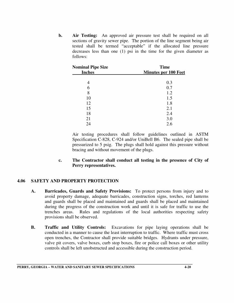
b. Air Testing: An approved air pressure test shall be required on all
sections of gravity sewer pipe. The portion of the line segment being air
tested shall be termed “acceptable” if the allocated line pressure
decreases less than one (1) psi in the time for the given diameter as
follows:
Nominal Pipe Size Time
Inches Minutes per 100 Feet
4 0.3 6 0.7 8 1.2 10 1.5 12 1.8 15 2.1 18 2.4 21 3.0 24 2.6
Air testing procedures shall follow guidelines outlined in ASTM Specification C-828, C-924 and/or UniBell B6. The sealed pipe shall be pressurized to 5 psig. The plugs shall hold against this pressure without bracing and without movement of the plugs.
c. The Contractor shall conduct all testing in the presence of City of Perry representatives.
4.06 SAFETY AND PROPERTY PROTECTION
A. Barricades, Guards and Safety Provisions: To protect persons from injury and to
avoid property damage, adequate barricades, construction signs, torches, red lanterns and guards shall be placed and maintained and guards shall be placed and maintained during the progress of the construction work and until it is safe for traffic to use the trenches areas. Rules and regulations of the local authorities respecting safety provisions shall be observed.
B. Traffic and Utility Controls: Excavations for pipe laying operations shall be
conducted in a manner to cause the least interruption to traffic. Where traffic must cross open trenches, the Contractor shall provide suitable bridges. Hydrants under pressure, valve pit covers, valve boxes, curb stop boxes, fire or police call boxes or other utility controls shall be left unobstructed and accessible during the construction period.
PERRY, GEORGIA – WATER AND SANITARY SEWER SPECIFICATIONS 4-20
C. Flow of Drains and Sewers Maintained: Provisions shall be made for the flow of
storm and sanitary sewers, drains and water courses encountered during construction, and the structures which may have been disturbed shall be satisfactorily restored upon completion of work.
D. Protection
1. General: Return all items and all areas disturbed, directly or indirectly by work
under these specifications, to their original condition or better as quickly as possible after work is started.
2. Man-Made Improvements: Protect or remove and replace with the Owner’s
approval, all fences, piers, docks, walkways, mailboxes, pipe lines, drain culverts, power and telephone lines and cables, and other improvements that may be encountered in the work.
3. Cultivated Growth: Do not disturb cultivated trees or shrubbery unless
approved by the Owner. Any such trees or shrubbery which must be removed shall be heeled in and replanted under the direction of an experienced nurseryman.
4. Cutting of Trees: Do not cut trees for the performance of the work except as
absolutely necessary. Protect trees that remain in the vicinity of the work from damage from equipment. Do not store spoil from excavation against the trunks. Remove excavated materials stored over the root system of trees within thirty (30) days to allow proper natural watering of the root system. Repair any damaged trees over three inches (3”) in diameter, not to be removed under the direction of an experienced nurseryman. All trees and brush that require removal shall be promptly and completely removed from the work area and disposed of by the Contractor. No stumps, wood piles, or trash piles will be permitted on the work site. The fruit trees encountered in the line right-of-way must be either transplanted or replaced and guaranteed to live for twelve (12) months.
5. Erosion Control: Plan excavation work to prevent erosion and the washing of
soil into adjacent streams. Limit the amount of open excavation at any one time. Place spoil in the proper place and keep natural water routes open. All erosion control procedures must comply with the Georgia Erosion and Sedimentation Control Act.
6. Disposal of Rubbish: Dispose of all materials cleaned and grubbed during the
construction of the project in accordance with the applicable codes and rules of the appropriate regulatory agencies; county, state and federal.
PERRY, GEORGIA – WATER AND SANITARY SEWER SPECIFICATIONS 4-21

SECTION NO. 5
SEWER MANHOLES
5.01 DESCRIPTION
This item shall govern the construction, manholes and manhole drop connections, complete in
place including the furnishing, adjustment to grade and installation of manhole frames and
covers.
5.02 MATERIALS
A. Cast Iron: Cast iron manhole frames, covers and steps shall conform to the shape and
dimensions shown on the detailed drawings and shall be clean and perfect, free from
sand and blow holes or other defects. Cast iron shall conform to ASTM Designation A-
48 for Class No. 20 gray cast iron. No casting will be accepted which weighs less than
95 percent of design weight. Shop drawings shall indicate design weight and provide
sufficient dimensions for checking. Cast iron manhole steps shall be coated with a non-
corrosive material such as plastic or they shall be manufactured of a non-corrosive
material such as aluminum, galvanized metal or other material approved by the engineer.
All castings shall be thoroughly cleaned in the shop and given two (2) coats of approved
bituminous paint before rusting occurs.
Design Manufacturer’s Type Weight Reference_______
Traffic 450 # Neenah R-1712B
Watertight Traffic 400 # Neenah R-1916F1
Vented 410 # Neenah R-1781
All frames and covers shall have machined horizontal bearing surfaces.
Bolt-down covers shall be equipped with four (4) each one-half-inch (1/2”) stainless
steel bolts and a one-eighth-inch (1/8”) neoprene O-ring gasket. Cover shall be rotatable
and interchangeable. Bolt holes shall be bore through so that debris entering the bolt
hole will fall into the manhole.
B. Brick: Bricks for manholes shall be first quality, sound, hard-burned, perfect shaped
brick presenting a smooth regular shape. Bricks shall not absorb more than 16 percent of water by weight when submerged in water for 24 hours, having been in a thoroughly dry state prior to placing in water. Concrete brick for manholes will be accepted only for adjustment of frame to grade (eight inch (8”) maximum) and filler for manhole table contouring.
PERRY, GEORGIA – WATER AND SANITARY SEWER SPECIFICATIONS 5-1

C. Sewer Pipe and Fittings: All sewer pipe and fittings shall meet the requirements as
specified in Section No. 4, Sanitary Sewers. D. Mortar: All cement used in mortar shall conform to ASTM Designation C-150 and the
latest revision thereof. All mortar used shall be comprised of one (1) part Portland Cement and two (2) parts fine sand.
E. Concrete: Concrete shall be Class “A” and shall conform to the applicable provisions
of ASTM Designation C-150, C-175, C-33 (Aggregates). Class “A” concrete shall have a minimum 28-day compressive strength of 3,000 psi.
F. Joint Gasket: Preformed plastic gasket with primer to meet Federal Specification SS-
S-00210, “RAM-NEK” or approved equal. G. Waterproofing: Where called for on the plans, the Contractor shall apply exterior
waterproofing to concrete surfaces. Waterproofing shall be an Asphalt Base Coating TNEMEC 47-461 or an approved equal (10-12 mils DFT minimum thickness).
5.03 CONSTRUCTION METHODS A. All bedding materials shall be crushed stone unless shown or specified otherwise.
Crushed stone bedding material shall meet the requirements of Georgia Department of Transportation Specification 800.01 for No. 57 stone and be eight inches (8”) thick.
B. Manhole and manhole drop connections shall be constructed at the locations shown on
the plans. Manholes shall be to the depth shown on the plans or as directed by the engineer. Details of manholes and drop connections are shown on the plans and construction shall be in accordance with these details.
C. Where inlet leads and mains or lateral pipe sewers enter a manhole, such pipes shall be
cut off flush with the inside of the manhole and any irregularities shall be pointed up with mortar. All pre-cast manhole joints, both inside and outside, shall be wiped with mortar for a smooth surface.
D. The inverts of the sewer lines entering manholes at or near the flow line elevation of the
manhole shall be shaped and routed across the floor of the manhole using concrete and mortar to obtain a minimum of 1” drop across the manhole.
E. After the manhole construction has been completed to the proper elevation, the cast iron
manhole frame shall be set in a full bed of mortar and adjusted to the elevation established by the engineer.
PERRY, GEORGIA – WATER AND SANITARY SEWER SPECIFICATIONS 5-2

F. The two sides of the concrete encasement on standard drop connections which are
adjacent to the manhole shall extend four inches (4”) outside the bells of the pipe in the drop connection. The side of the encasement opposite the manhole shall be flush with the pipe bells. The entire drop connection shall be joined with the wall of the manhole in a solid mass of concrete. Drop connections shall be constructed at the time the manhole is constructed. Unless a lateral is to be immediately connected into the drop connection, it shall be plugged at the outer end of the wye or tee with a standard concrete pipe plug. A drop manhole shall be required if the invert of sewer entering manhole is 24” or more than the manhole invert.
G. Waterproofing: Waterproofing shall be applied to the outside of below grade concrete
surfaces of all manholes indicated on the plans. The bituminous waterproofing shall be applied according to manufacturing recommendations to a minimum thickness of 10-12 mils DFT.
H. Backfilling around manholes and drop connections shall be in accordance with the
applicable provisions for backfilling trenches specified in Section No. 4, Sanitary Sewers.
5.04 PRECAST SEWER MANHOLES AND WET WELLS
The Contractor shall furnish and install precast reinforced concrete manholes meeting all requirements of ASTM Designation C478-69. Reinforcing shall meet all requirements of ASTM A-185.
A. Types: Precast risers and grade rings shall be the eccentric cone type for manhole top
sections. B. Joints: The reinforced concrete manhole in riser sections, excepting grade rings, shall
be formed with male and female ends with rubber gasket rings between the male and female end to reduce infiltration and leakage.
C. Manhole Steps: Manhole steps that are cast or mortared into the walls of risers or
conical top sections shall be aligned in each section so as to form a continuous ladder with rungs equally spaced vertically not more than twelve inch (12”) centers. Steps shall be installed in manholes to within two feet (2’) of crown of lowest pipe.
D. Finished Grade: Precast manholes shall be furnished and set with proper allowance for
the cast iron frame and cover to be set at the correct finished grade as shown on the plans.
E. Dimensions: All precast manholes shall be a standard four feet (4’) inside diameter for
pipe sizes eight inch (8”) to twelve inch (12”), and five feet (5’) inside diameter for pipe sizes fifteen inch (15”) to thirty-six inch (36”).
PERRY, GEORGIA – WATER AND SANITARY SEWER SPECIFICATIONS 5-3
F. Brick: Bed bottom and sides of any bricks used with mortar. Apply a smooth coat of
mortar three-quarter-inch (3/4”) thick on the inside and outside.
G. Manhole Boots: Provide neoprene boot seals where sewer enters the manhole and wet
well. Holes for pipe entering or leaving shall be core-drilled at the factory.
H. Testing:
1. Vacuum Tests: The manhole, after proper preparation as noted above, shall be
vacuum tested prior to backfilling. The test head shall be placed at the inside of the
top of the cone section and the compression head inflated to 40psi to effect a seal
between the vacuum base and the manhole structure. Connect the vacuum pump to
the outlet port with the valve open. A vacuum of 10 inches of mercury shall be
measured for the vacuum to drop to 9 inches. The manhole shall pass if the time is
greater than 60 seconds for 48 inch diameter manholes. If the manhole fails the
initial test, necessary repairs shall be made and the manhole re-tested. Re-testing
shall proceed until a satisfactory test is obtained. All the tests shall be witnessed by
City of Perry inspectors.
2. Exfiltration Tests: The manhole, after proper preparation as noted above,
shall be filled with water. The maximum allowable leakage shall not exceed 8
gallons per foot of depth per 24 hours for 48 inch diameter manholes. Tests shall
last a minimum of eight hours. The manholes may be backfilled prior to testing.
PERRY, GEORGIA – WATER AND SANITARY SEWER SPECIFICATIONS 5-4

SECTION NO. 6
FORCE MAIN AND RELATED PIPING
6.01 SCOPE
This section of the Specifications describes products to be incorporated into the force main and
requirements for the installation and use of these items. The Contractor shall furnish all products and perform all labor necessary to fulfill the requirements of these Specifications.
6.02 GENERAL 1. Applicable Standards: Supply all products and perform all work in accordance with
applicable American Society for Testing and Material (ASTM), American Water Works Association (AWWA), American National Standards Institute (ANSI), or other recognized standards. Latest revisions of all standards are applicable. If requested by the Engineer, submit evidence that manufacturers have consistently produced products of satisfactory quality and performance for a period of at least two (2) years.
6.03 MATERIALS
Furnish all pipe, fittings, valves and all other materials required for completion of the work. All
materials shall be made in AMERICA. Furnish materials in accordance with the following: A. Ductile Iron Pipe (DIP): Ductile iron pipe shall conform to AWWA C151 and shall be
a minimum of Class 50. Sizes will be as shown on the drawings. Pipe and fittings shall be cement lined in accordance with AWWA C104. Fittings shall conform to AWWA C110 with rated working pressure of 250 psi. Pipe and fittings shall be furnished with a bituminous outside coating.
Joints shall be push-on type for pipe and standard mechanical or flanged joints for
fittings. Push-on and mechanical joints shall conform to AWWA C111. Restrained joint pipe (RJP) shall be either the bolted joint type, or modified push-on type with joint retrained using ductile iron components. Restrained joint pipe on piers shall have bolted joints and shall be specifically designed for clear spans of at least 36 feet. Restrained joint pipe where required shall be American, U.S. Pipe, Clow or equal.
Provide the appropriate gaskets for mechanical or flange joints. Gaskets for flange
joints shall be made of 1/8-inch thick cloth reinforced rubber; gaskets may be ring type or full face type.
PERRY, GEORGIA – WATER AND SANITARY SEWER SPECIFICATIONS 6-1
Provide the necessary bolts for mechanical of flange connections. Bolts for flange
connections shall be steel with American Regular unfinished square or hexagon heads.
Nuts shall be steel with American Standard Regular hexagonal dimensions, all as
specified in ANSI B 17.2. All bolts and all nuts shall be threaded in accordance with
ANSI B.1.1 Coarse Thread Series, Class 2A and 2B fit.
All pipe shall be furnished in lengths of at least 18 feet.
Acceptance will be on the basis of the Engineer’s review and the manufacturer’s written
certification that the pipe was manufactured and tested in accordance with the applicable
standards.
B. PVC Pipe: For sizes four inch (4”) through twelve inch (12”), PVC pipe shall meet all
requirements of AWWA C900, Class 100, DR 25 with single rubber gasket push-on
joint conforming to ASTM D-3139.
C. Fittings: Fittings shall be ductile iron fittings in accordance with ANSI/AWWA
C110/A21.10. Working pressure shall be a minimum of 250 psi. Fittings shall have a
nominal wall thickness of Class 54 Ductile Iron Pipe. Cement lining and seal coating
shall be in accordance with ANSI/AWWA C104/A21.4. Provide the necessary bolts and
gaskets for mechanical joint fittings. RUSCO fittings are not acceptable.
D. Polyethylene Film Encasement: Each location of a ductile iron fitting within ten feet
(10’) of a natural gas line with Cathodic Protection will require polyethylene
encasement.
The polyethylene film shall be manufactured of virgin polyethylene material conforming
to the requirements of ASTM Standard Specifications D-12448-78. Polyethylene film
shall have a minimum thickness of 0.008 in.
The polyethylene encasement shall prevent contact between the pipe and the
surrounding backfill and/or bedding material but it is not intended to be a completely
airtight and watertight enclosure. Overlaps shall be secured by the use of adhesive tape,
plastic string or other material capable of holding the polyethylene encasement in pace
until backfilling operations are complete.
E. Pipeline Casing Spacers: Each pipeline casing spacer shall be two (2) piece 14 gauge
T-304 stainless steel with corrosion resistant clamps for carrier pipe. The runners shall
be ultra high molecular weight polymer to resist abrasion and sliding wear and
configured to center the carrier pipe in the casing pipe with adequate support. Spacing
shall be as recommended by the manufacturer. Spacers shall be Cascade or an approved
equal.
PERRY, GEORGIA – WATER AND SANITARY SEWER SPECIFICATIONS 6-2

6.04 HANDLING MATERIALS
A. Unloading: Furnish equipment and facilities for unloading, handling, distributing and
storing pipe, fittings, valves and accessories. Make equipment available at all times for
use in unloading. Do not drop or dump materials. All materials dropped or dumped will
be subject to rejection without additional justification.
B. Handling: Handle pipe, fittings, valves and accessories carefully to prevent shock or
damage. Handle pipe by rolling on skids, forklift or front loader. Do not use material
damaged in handling.
C. Distribution: Distribute and place pipe and materials to not interfere with traffic. Do
not string pipe more than 1,000 feet beyond the area where pipe is being laid. Do no
obstruct drainage ditches.
D. Storage: Store all pipe which cannot be distributed along the route. Make
arrangements for the use of suitable storage areas. Do not interfere with other
contractors right to access.
6.05 CONSTRUCTION ALONG HIGHWAYS, STREETS AND ROADWAYS
Install pipe lines and accessories along highways, streets and roadways in accordance with the
applicable regulations of the Georgia Department of Transportation with reference to
construction operations, safety, traffic control, road maintenance and repair. Boring of casing
pipe shall meet the minimum specifications as described in Section “Sanitary Sewers”.
A. Protection of Traffic: Provide and maintain suitable signs, barricades and lights for
protection of traffic. Replace all highway signs removed for construction as soon as
possible. Do not close or block any highway, street or roadway without first obtaining
permission from the proper authorities.
Provide flagmen to direct and expedite the flow of traffic.
B. Construction Operations: Perform all work along highways, streets and roadways to
least interfere with traffic.
(1) Stripping: Where the pipe line is laid along the road shoulders, strip and
stockpile all sod, topsoil and other material suitable for shoulder restoration.
(2) Trenching, Laying and Backfilling: Do not open the trench any further ahead
of pipe laying operations than is necessary. Backfill and remove excess material
immediately behind laying operations. Complete excavation and backfill for any
portion of the trench in the same day.
PERRY, GEORGIA – WATER AND SANITARY SEWER SPECIFICATIONS 6-3
(3) Shaping: Reshape damaged slopes, side ditches and ditch lines immediately
after completing backfilling operations. Replace topsoil, sod and any other
materials removed from shoulders.
C. Excavated Materials: Do not place excavated material along highways, streets and
roadways in a manner which obstructs traffic. Sweep all scattered excavated material
off the pavement.
D. Drainage Structures: Keep all side ditches, culverts, cross drains and other drainage
structures clear of excavated material and free to drain at all times.
E. Maintaining Highways, Streets, Roadways and Driveways: Maintain streets,
highways and roadways in suitable condition for movement of traffic until completion
and final acceptance of the work. Use steel running plate to maintain traffic until
pavement replacement is completed.
Note: Traffic must be maintained at all times. When one lane is closed, flagmen
must be utilized to maintain traffic flow.
Repair all driveways that are cut or damaged immediately. Maintain them in a suitable
condition for use until completion and final acceptance of the work.
6.06 EXISTING UNDERGROUND UTILITIES AND OBSTRUCTIONS
It is the responsibility of the Contractor to locate all existing utilities along the path of his
construction. The drawings shall indicate underground utilities or obstructions that are known
to exist. Where these or unforeseen underground utilities are encountered, the location and
alignment force main may be changed, upon written approval of the Engineer and the Owner, to
avoid interference. The Contractor shall record the location of all underground utilities which
are encountered and are not shown on the drawings. These locations will be incorporated into
the “Drawings of Record”.
6.07 LAYING PVC PIPE
A. General: Unless specifically indicated on the plans or called for in the specifications,
PVC lines shall be constructed of rubber gasket joint pipe, with mechanical joint fittings.
B. Construction Methods:
(1) Field Inspection: All pipe and accessories shall be laid, jointed, tested for
defects and for leakage with pressure in the manner herein specified in the
presence of the Engineer or his authorized representative and subject to their
approval.
PERRY, GEORGIA – WATER AND SANITARY SEWER SPECIFICATIONS 6-4

(2) Handling Pipe and Accessories:
(a) Care: PVC pipe, fittings, valves and other accessories shall be unloaded
at the point of delivery, hauled to and distributed at the site of the project
by the contractor; they shall at all times be handled with care to avoid
damage. In loading and unloading they shall be lifted by hoists or slid or
towed on skid-ways in such a manner as to avoid shock. Under no
circumstances shall they be dropped. Pipe handled on skid-ways must
not be skidded or rolled against pipe already on the ground.
(b) At Site of Work: In distributing the material at the site of the work, each
piece shall be unloaded opposite or near the place where it is to be laid in
the trench and shall be laid on high ground so that it will not be in a
drainage way.
(c) Bell Ends, How Faced: Pipe shall be placed on the site of the work
parallel with the trench alignment and with the bell ends facing the
direction in which the work will proceed unless otherwise directed by the
Engineer.
(d) Pipe Kept Clean: The interior of all pipe, fittings and other accessories
shall be kept free from dirt and foreign matter at all times.
(e) Detecting PVC Pipe: All PVC force main pipe shall have 12 gauge
stranded, insulated, copper wire placed on each pipe crown for
detection purposes. Detectible metalized tape shall also be installed over
all PVC pipe. Tape will be equal to “Terra Tape” Type D for force main
as manufactured by Griffolyn Company, Inc. of Houston, Texas
(distributed by Corrosion Specialties, Inc., Tucker, Georgia). Detection
tape shall be buried 2’ – 0” below the ground surface above the force
main.
(3) Alignment and Grade:
(a) General: All pipe shall be laid and maintained in the required lines and
grades, with fittings and valves at the required locations, with joints
centered and spigots home, and with all valve stems plumb. Unless
shown otherwise grade shall be positive in the direction of flow.
(b) Depth of Pipe: The top of the barrel of the pipe shall have a
minimum cover of forty-eight inches (48”).
PERRY, GEORGIA – WATER AND SANITARY SEWER SPECIFICATIONS 6-5

(4) Excavation and Preparation of Trench:
(a) Description: The trench shall be dug to the alignment and depth
required and not to exceed 200 feet in advance of the pipe laying. The
trench shall be braced if necessary and drained in order that workmen
therein, may work safely and efficiently. It is essential that the discharge
from any pumps be led to natural drainage channels, to drains or to storm
sewers.
(b) Width: Minimum width of trench shall be six inches (6”) outside the
barrel of the pipe on each side of pipe. Maximum width of trench shall
be nine inches (9”) outside the barrel of the pipe on each side of pipe.
Sides of trench shall be dug and maintained substantially vertically to a
height of twelve inches (12”) above the pipe.
(c) Pipe Foundation: The pipe shall be laid upon a sound earthen
foundation cut true and even so that the barrel of the pipe will have a
bearing for its full length. If unsuitable foundation material is
encountered, crushed stone stabilization if directed by the Engineer will
be required. Crushed stone trench stabilization shall be #57 stone paid
for at the unit price bid per ton in the Proposal.
(d) Correcting Faulty Grade: Any part of the trench excavated below
grade shall be corrected with approved materials, thoroughly compacted.
(e) Bell Holes, Required: Bell holes of ample dimensions shall be dug in
trenches at each joint to permit the joint to be made properly.
(f) Braced and Sheeted Trenches: Wherever necessary to prevent caving,
excavations shall be adequately sheeted and braced. Where sheeting and
bracing are used, the trench width shall be increased accordingly. Trench
sheeting shall remain in place until the pipe has been laid, tested for
defects and repaired if necessary, and the earth around it compacted to a
depth of two feet (2’) over the top of the pipe.
(g) Care of Surface Materials for Re-Use: If local conditions permit their
re-use, all surface materials suitable for re-use in restoring the surface
shall be kept separate from the general excavation material.
PERRY, GEORGIA – WATER AND SANITARY SEWER SPECIFICATIONS 6-6

(h) Manner of Piling Excavated Materials: All excavated materials shall
be piled in a manner that will not endanger the work and that will avoid
obstructing sidewalks and driveways. Gutters shall be kept clear or other
provisions made for street drainage.
(i) Trenching by Machine or by Hand: The use of trench digging
machinery will be permitted except in places where operation of same
will cause damage to existing structures above or below ground; in which
case hand methods shall be employed. Excavation shall be made by
ladder type machine or backhoe.
(5) Pipe Handling:
(a) Manner of Hauling Pipe and Accessories: Proper implements, tools
and facilities shall be provided and used by the Contractor for the safe
and convenient prosecution of the work. All pipe, fittings and valves
shall be carefully lowered into the trench piece by piece by means of
derrick ropes or other suitable tools or equipment, in such manner as to
prevent damage to pipe or pipe coating. Under no circumstances shall
pipe or accessories be dropped or dumped into the trench.
(b) Inspection: Before lowering and while still suspended, the pipe shall be
inspected for defects. Any defective, damaged or unsound pipe shall be
rejected.
(c) Pipe Kept Clean: All foreign matter or dirt shall be removed from the
pipe, and it shall be kept clean by approved means during and after
laying.
(d) Laying of the Pipe: The spigot shall be centered in the bell, the pipe
forced “home” and brought into true alignment; it shall be secured there
by earth carefully tamped under and on each side of it, excepting at the
bell holes. Care shall be taken to prevent dirt from entering the joint
space. No “blocking up” of pipe or joints will be permitted. The joint
shall be made as hereinafter described.
(e) Trench Water Entering Pipe: At times when pipe laying is not in
progress, the open ends of the pipe shall be closed by approved means
and no trench water shall be permitted to enter the pipe.
(f) Cutting Pipe: Cutting of pipe for inserting valves, fittings or closure
pieces shall be done in a neat workmanlike manner without damage to the
pipe.
PERRY, GEORGIA – WATER AND SANITARY SEWER SPECIFICATIONS 6-7

(g) Bell Ends Face Direction of Laying: Unless otherwise directed, pipe
shall be laid with bell ends facing in the direction of laying; and for lines
on an appreciable slope, bells shall, at the discretion of the Engineer, face
up-grade.
(h) Permissible Deflections at Joints: Wherever necessary to deflect pipe
from a straight line, either in the vertical or horizontal plane to avoid
obstructions, the degree of deflection shall be approved by the Engineer.
(i) Unsuitable Conditions for Laying Pipe: No pipe shall be laid in water,
or when the trench conditions or the weather is unsuitable for such work
except in an emergency.
(6) Jointing Pipe-Mechanical Joints: The following steps shall be taken in making
mechanical joints:
(a) All lumps, blisters and excess coal-tar enamel shall be removed from
socket and spigot of the pipe.
(b) Wash socket and plain end with soapy water containing chloride solution;
then slip gland and gasket over plain end. The small side of gasket and
lip gland shall face bell.
(c) Paint gasket with soapy solution containing chlorine.
(d) Push gasket into position, being sure it is evenly seated in socket.
(e) Slide gland into position; insert bolts and run nuts up finger tight.
(f) Tighten bolts to uniform tightness with correct ratchet wrench. The first
bolt tightened shall be the bottom bolt, then top. All other bolts shall be
tightened in sequence at 180 degrees apart.
(7) Setting Fittings:
(a) General: Pipe fittings shall be set and joined to new pipe in the manner
heretofore specified for cleaning, laying and jointing pipe.
(8) Concrete Backing: Concrete having compressive strength of not less than 1,500
psi shall be used as a cradle or backing where shown on the plans. Bends
exceeding 11 ¼ degrees shall be backed with concrete as a thrust backing.
Backing shall be placed between solid ground and the fitting to be anchored.
The backing shall be so placed that the pipe fitting joints will be accessible for
repair. No extra payment will be made for the concrete backing.
PERRY, GEORGIA – WATER AND SANITARY SEWER SPECIFICATIONS 6-8

(9) Backfilling, Cleaning Up and Maintaining Surfaces:
(a) Time of Backfilling: As soon as practicable after the completion of
laying and jointing of the pipe, the trench shall be backfilled, and at no
time shall the completed backfilling of the trench be more than 300 feet
behind the pipe laying.
(b) Backfill Procedure at Pipe Zone: Select backfill material free from
rock fragments shall be deposited in the trench simultaneously on both
sides of the pipe for the full width of the trench and to an elevation of six
inches (6”) above the top of the barrel of the pipe. The backfill material
shall be moistened if necessary, tamped in thin (about four inches (4”)
layers and thoroughly compacted under and on each side of the pipe to
provide solid backing against the external surface of the pipe.
(c) Backfill Procedure Above the Pipe Zone: Succeeding layers of backfill
may contain coarser materials, and shall be compacted thoroughly to the
natural ground surface.
(d) Procedure Where Settlement is Important: Where it is important that
the surface of the backfill be made safe for vehicular traffic at unpaved
street crossings and along existing unpaved streets, the upper thirty-six
inches (36”) of backfill shall be approved moist material, thoroughly
compacted in eight inch (8”) layers by tamping, and shall be brought to
the required surface grade.
(e) Procedure Where Settlement is Unimportant: Where pipe is laid
behind curbs or outside city streets, tamping may be omitted in the layers
above those described under Paragraph (a) and (b) and the backfill shall
be neatly rounded over the trench to a sufficient height to allow for the
settlement to grade after consolidation.
(f) Compaction Test: Where settlement is important, the Contractor shall
furnish the City of Perry proof of compaction at pavement subgrade.
Test shall be at each street or drive crossing or at intervals not exceeding
400 feet in continuous pavement areas. Contractor shall incur all cost for
compaction test performed by a testing laboratory selected by the
Contractor and approved by the City of Perry.
(g) Deficiency of Backfill, by Whom Supplied: Any deficiency in the
quantity of material for backfilling the trenches, or for filling depressions
caused by settlement, shall be supplied by the Contractor.
PERRY, GEORGIA – WATER AND SANITARY SEWER SPECIFICATIONS 6-9

(h) Restoration of Surfaces: The Contractor shall replace all curbing,
sidewalks, gutters, shrubbery, fences, sod and other surfaces disturbed to
a condition equal to or better than that before the work began, furnishing
all labor and materials incidental thereto and complete the work in a
manner satisfactory to the Engineer. Replacement of street base and
surface removed to permit installation of pipe lines shall be provided for
elsewhere in these Specifications.
(i) Backfill Under Paved Streets: Backfill under paved streets shall be
thoroughly compacted, and as shown on the detailed drawings.
(j) Surplus Earth: Surplus excavated materials from trenches in streets or
at railroad crossings shall be disposed of by the Contractor at his expense
and in a manner satisfactory to the Engineer.
(k) Cleaning Up: Surplus pipe line materials, tools, surplus excavated
materials, rubbish and temporary structures shall be removed by the
Contractor and the construction site shall be left clean to the satisfaction
of the Engineer. The line shall be cleaned up immediately after
satisfactory pressure test has been made.
(l) Maintenance of Surfaces: Following the Certification of Completion by
the Engineer, the Contractor shall maintain the surface of the unpaved
trenches, adjacent curbs, sidewalks, gutters and other surfaces disturbed
for a period of three (3) months thereafter.
All materials and labor required for the maintenance of the trenches and
adjacent structures shall be supplied by the Contractor and the work shall
be done in a manner satisfactory to the Engineer.
6.08 HYDROSTATIC TESTING
A. Pressure and Leakage Tests:
(1) Pressure During Test: Immediately after the force main pipe has been laid and
backfilled, but prior to the placement of pavement, each section of newly laid
pipe shall be subjected to a leakage and pressure test. For any section being
tested the pressure applied shall be such that at the highest point in the section,
the pressure shall be 75 pounds per square inch (psi) or at least two-thirds (2/3)
of pipe rated pressure whichever is greater.
(2) Duration of Test: The duration of each pressure test shall be two (2) hours.
PERRY, GEORGIA – WATER AND SANITARY SEWER SPECIFICATIONS 6-10

(3) Procedures: Each valved section of pipe shall be slowly filled with water and
the specified test pressure, measured at the point of highest elevation shall be
supplied by means of a pump connected to the pipe in a satisfactory manner.
The pump, pipe connection and all necessary apparatus, gauges and meters shall
be furnished by the Contractor. The Contractor shall furnish all necessary labor
and assistance in conducting the tests. The Owner will furnish, through
connections made by the Contractor to existing mains, water for filling the lines
for making the test.
(4) Expelling Air Before Tests: Before applying the specified test pressure, all air
shall be expelled from the pipe. To accomplish this, taps shall be made, if
necessary, at points of highest elevation and afterwards tightly plugged.
(5) Examination Under Pressure: At intervals during the test, the route of the pipe
line shall be inspected to locate any leaks or breaks. Any cracked or defective
joints, cracked or defective pipe, fittings or valves discovered in consequence of
this pressure test shall be removed and replaced with sound material in the
manner provided and the test shall be repeated until satisfactory results are
obtained.
(6) Permissible Leakage: Leakage shall be defined as the quantity of water that
must be supplied into the newly laid pipe, of any valved section thereof, to
maintain the specified leakage test pressure after the pipe has been filled with
water and the air in the pipeline has been expelled. No installation will be
accepted if leakage is greater than that determined by the formula:
L = SD(P)0.5
7400
Where: L is the allowable leakage, in gallons per hour; S is the number of joints in the length of pipeline tested; D is the nominal diameter of the pipe, in inches; and P is the average test pressure during the leakage test, in pounds per square inch gauge. Leakage values determined by the above formula are to be found in the following table:
ALLOWABLE LEAKAGE
WITH ELASTOMETRIC JOINTS IN GALLONS PER HOUR PER 1000 FEET OF PIPE AT 75 PSI
Nominal Pipe Size (Inches) Allowable Leakage 4" .23 6" .35 8" .46
PERRY, GEORGIA – WATER AND SANITARY SEWER SPECIFICATIONS 6-11
6.09 STREAM AND DITCH CROSSING
At all points where banks of streams or drainage ditches are disturbed by excavation or where
natural vegetation is removed, carefully compact backfill. Place rip-rap to prevent subsequent
settlement and erosion as shown on the plans or as directed by the Engineer.
This requirement applies equally to construction beside a stream or drainage ditch as well as
crossing stream or drainage ditch. Place rip-rap as shown on the plans or as directed by the
Engineer, a distance of not less than ten feet (10’) upstream and ten feet (10’) downstream from
any disturbed area. Extend rip-rap from one foot (1’) below stream-bed to top of bank. Place to
conform with the natural slope of the stream bank.
A. Stone Rip-Rap: Use sound, tough, durable stones resistant to the action of air and
water. Slabby or shaley pieces will not be acceptable Specific gravity shall be 2.0 or
higher.
Minimum weight of individual stones shall be fifty pounds (50#). The maximum
allowable dimension for an individual stone is 24 inches. The minimum allowable
dimension for an individual stone is six inches (6”). At least 50 percent of the stones
shall have a minimum dimension of twelve inches (12”).
Embed stone rip-rap by and so as to form a compact layer at least twelve inches (12”)
thick. Place rip-rap in such a way that the smaller stones are not segregated but evenly
distributed. Place chinking stones in the crevices between the larger stones so that a
dense, well graded mass is produced.
6.10 MEASUREMENT AND PAYMENT
Force mains shall be measured and paid based on the linear foot measure from centerline of
fittings for the various sizes shown in the Proposal. Pipe installation in casing shall be
measured and paid based on the linear foot measure from end of casing to end of casing and
include casing spacers. Other items shall be measured and paid based on the contract unit price
for each complete item installed and tested. Fittings shall be measured and paid based on the
weight of a standard cast iron mechanical joint fitting (AWWA C110) (body only).
Trench stabilization materials (#57 stone) shall be measured by the ton based upon tickets
provided by the material supplier and verified by the Owner. Stabilization material will be used
only in areas where necessary as approved by the Engineer.
Steel casing pipe based under highways or roadways shall be measured from end of casing to
end of casing and based on the linear foot measure.
PERRY, GEORGIA – WATER AND SANITARY SEWER SPECIFICATIONS 6-12

SECTION 7
WETWELL MOUNTED PUMP STATIONS
7.01 GENERAL
The contractor shall furnish and install one factory-built, automatic pumping station as manufactured
by Smith & Loveless, Inc., Lenexa, Kansas. The station shall be complete with all needed equipment,
factory-installed on a welded steel base with fiberglass cover.
The principal items of equipment shall include two vertical, close-coupled, motor driven, vacuum
primed, non-clog pumps; valves; internal piping; central control panel with circuit breakers; motor
starters and automatic pumping level controls; heater; ventilating blower; priming pumps and
appurtenances; and all internal wiring.
Each pump station installation shall be enclosed within a chain link fence. Also to be provided will be
a 1” waterline with yard hydrant and work light.
7.02 CONSTRUCTION
The station shall be constructed in one complete, factory-built assembly. It shall be sized to rest on the
top of the wet well as detailed in the construction drawings. The supporting floor plate shall be
minimum 3/8” thick steel with reinforcing, as required, to prevent deflection and ensure an absolutely
rigid support. Steel plate shall meet or exceed ASTM A-36 specifications.
The pump station shall be enclosed by a hinged fiberglass cover made of molded reinforced
orthophthalic polyester resins with a minimum of 30% glass fibers with a minimum average length of
1-¼”. The outside of the enclosure shall be coated with a polyester protective in-mold coating for
superior resistance to weathering, ultra-violet radiation, yellowing and chalking. The completed
fiberglass enclosure shall be resistant to mold, mildew, fungus and corrosive liquids and gasses
normally found in pump station environments. The dimensions of the enclosure shown on the drawings
shall be considered a minimum, for internal component clearances and accessibility, and nothing
smaller will be acceptable. The cover shall have a suitable drip-lip around the edge and shall be
provided with a hasp and staple connection to the floor plate to allow the pump chamber to be locked
with a padlock.
The cover shall be attached with a multi segment stainless steel hinge, constructed of 7 gauge
(minimum) type 304 stainless steel with a 3/8” diameter stainless steel pin and supporting at least 75%
of the width of one end. Stainless steel bolts with tamperproof heads and a full width 3/8” thick
anodized aluminum backing plate shall anchor the hinge to the fiberglass cover.
PERRY, GEORGIA – WATER AND SANITARY SEWER SPECIFICATIONS 7-1
Dual high pressure gas struts shall be provided to counteract the dead weight of the cover assembly and
limit the maximum lifting force required for opening to less than 20 pounds. The cover shall be self-
latching upon opening, with a manually operated release for closing. Duplex heavy gauge safety chains
shall be provided to prevent over-extension. All hardware and components of the cover assembly
which are exposed to the weather shall be constructed of corrosion resistant materials.
Heavy extruded aluminum, adjustable ventilating louvers shall be provided on each end of the
fiberglass cover, which are capable of being closed during cold weather operation.
An aluminum manway cover fabricated of ¼” treadplate, located exterior to the fiberglass pump
chamber shall be provided, complete with padlocking provisions. The manway shall be an integral part
of the station floor plate and provide access to the wet well. The minimum open area of the manway
access into the wetwell shall be at least 4.2 square feet.
The manway cover shall have a three color 7” x 10” (minimum) corrosion resistant sign permanently
affixed to it, reading “DANGER – Before Entering, Test For Explosive Gasses. Test For Oxygen
Deficiency. Supply Fresh Air To Work Area”.
Enclosures utilized to house the valve train and/or controls, which are defined under OSHA Article
29CFR, Parts 1910 as a Confined Space shall not be acceptable.
To allow on-site maintenance of the pumps, a stanchion with lifting arm shall be provided to lift each
pump. The lifting arm shall have a hook over the center of the motor to support a hoist (provided by
others) for removal of the motors, impellers and pumps from the station.
The pump casings and discharge piping shall be mounted in relation to the floor plate as detailed in the
construction drawings. The suction and discharge connections, where they pass through the floor, shall
be sealed by gaskets, rather than being welded, to allow adjustment and replacement.
7.03 WELDING
All steel structural members shall be joined by electric arc welding with welds of adequate section for
the joint involved. Structural welding shall be preformed in accordance with AWS standards and
procedures.
PERRY, GEORGIA – WATER AND SANITARY SEWER SPECIFICATIONS 7-2

7.04 PROTECTION AGAINST CORROSION
All structural steel surfaces shall be factory blasted with steel grit, in an environmentally controlled
booth, to remove rust, mill scale, weld slag, etc. Sandblasting is specifically prohibited. All weld
spatter and surface roughness shall be removed by grinding. Surface preparation shall comply with
SSPC-SP6 specifications. Immediately following cleaning, a single 6-mil dry film thickness of
VERSAPOX®
, a self-priming Cycloaliphatic Amine Epoxy, shall be factory applied. This coating shall
be as formulated by Smith & Loveless for abrasion and corrosion resistance.
Stainless steel, aluminum and other corrosion-resistant surfaces shall not be coated. Carbon steel
surfaces not otherwise protected shall be coated with a suitable non-hardening rust preventative
compound. Auxiliary components such as the electrical enclosure, ventilating blower and vacuum
pumps shall be furnished with the original manufacturer’s coating.
Finish coating shall be accomplished prior to shipment of the station from the factory and shall comply
fully with the intent of these specifications. A touch-up kit shall be provided by the pump station
manufacturer for repair of any mars or scratches occurring during shipping and installation. This kit
shall contain detailed instructions for use and shall be the same material as the original coating.
7.05 MAIN PUMPS
The pumps shall be vertical, centrifugal non-clog type of heavy cast iron construction, especially
designed for the use of mechanical seals and vacuum priming. In order to minimize seal wear caused
by linear movement of the shaft, the shaft bearing nearest the pump impeller shall be locked in place so
that end play is limited to the clearance within the bearing. To minimize seal wear resulting from shaft
deflection caused by the radial thrust of the pump, the shaft from the top of the impeller to the lower
bearing supporting the impeller shall have a minimum diameter of 1-7/8” for motor frame sizes 213
through 286; 2-1/8” for motor frame sizes 324 and 326; and 3” for frame 364 and larger. The
dimension from the lowest bearing to the top of the impeller shall not exceed 6”. The motor shaft shall
be directly connected to the impeller without the use of drive belts or couplings, which require
alignment and maintenance, and which increase power consumption due to their inherent energy losses.
Pumps with less than a standard 4” suction or 4” discharge connection, or with less than a 3” spherical
solids handling capacity will be rejected for this application.
The oversized shaft incorporating oversized bearings and heavier bearing frame construction provides
for extended mechanical seal, bearing and overall pump/motor life. Since the larger shaft with the
specified minimum overhang is the key to heavier, more rigid construction throughout, no deviation
from the specified shaft diameter or tolerances will be allowed.
The bearing nearest the impeller shall be designed for the combined thrust and radial load. The upper
bearing shall be free to move in a linear direction with the thermal expansion of the shaft and shall
carry only radial loads.
PERRY, GEORGIA – WATER AND SANITARY SEWER SPECIFICATIONS 7-3

The shaft shall be solid stainless steel through the mechanical seal to eliminate corrosion and abrasive
rust particles. Removable shaft sleeves will not be acceptable if the shaft under the sleeve does not meet
the specified minimum diameter.
The pump shall have an integral adapter providing a large water reservoir above the impeller to provide
for positive exclusion of air from the impeller. The seal shall be inside this area to assure lubrication.
Pumps which do not use hollow priming adapters for positive lubrication of the seal will not be
acceptable. Self priming pumps are specifically unacceptable due to the need for suction check valves,
air vent piping and the possibility of overheating and damaging the pump or producing steam or high
temperatures in the pump, which may be a hazard to the operator, when the pump is run dry. The pump
controls must be set so that the main pumps cannot be turned on unless they are filled with liquid, and
the pump is completely primed.
The pump shall be constructed so as to permit priming from the lower pressure area behind the
impeller. Priming from high pressure connections, which tends to cause solids to enter and clog the
priming system, will not be acceptable. The priming bowl shall be transparent, enabling the operator to
monitor the priming level.
The pump shall be arranged so that the rotating element can easily be removed from the casing without
disconnecting the electrical wiring or disassembling the motor, impeller, backhead or seal, so that any
foreign object may be removed from the pump or suction line. Enclosed impellers must be used to
avoid the necessity of wear plates and the associated costs of replacement and maintenance of wear
plate clearances with semi-open impellers.
The pump shaft shall be sealed against leakage by a single mechanical seal constructed so as to be
automatically drained and primed each time the pump is drained and primed. Water which lubricates
the mechanical seal shall be automatically drained from around the seal if the pump loses prime in
order to allow both the pump and the seal to be drained, thereby preventing freezing and breakage of
the seal during power outages in sub-freezing temperatures.
The seal shall be of carbon and ceramic materials with the mating surfaces lapped to a flatness
tolerance of one light band. The rotating ceramic shall be held in mating position with the stationary
carbon by a stainless steel spring. The entire seal assembly shall be held in place by a bronze seal
housing to prevent excessive heat build-up. Use of cast iron or other ferrous material for the seal
housing which will rust and damage the seal, shortening its life, will not be acceptable.
The pump volute shall be furnished with mounting lugs and bolted to the station floor plate, forming a
gas-tight seal.
PERRY, GEORGIA – WATER AND SANITARY SEWER SPECIFICATIONS 7-4

7.06 NON-CLOG TWO-POT IMPELLER
The pump impeller shall be of the enclosed two-port type made of close-grained cast iron and shall be
balanced. The eye of the impeller as well as the ports shall be large enough to permit the passage of a
sphere 3” in diameter in accordance with nationally recognized codes. The impeller shall be keyed
with a stainless steel key and secured to the motor shaft by a stainless steel cap screw equipped with a
Nylock or other suitable self-locking device. The impeller shall not be screwed or pinned to the motor
pump shaft and shall be readily removable without the use of special tools. To prevent the buildup of
stringy materials, grit and other foreign particles around the pump shaft, all impellers less than full
diameter shall be trimmed inside the impeller shrouds. The shrouds shall remain full diameter so that
close minimum clearance from shrouds to volute is maintained. Both the end of the shaft and the bore
of the impeller shall be tapered to permit easy removal of the impeller from the shaft.
7.07 MOTORS
The pump motors shall be vertical, solid shaft, NEMA P-base, squirrel-cage induction type, suitable for
3 phase, 60 cycle, 230 or 460 volt electric current. They shall have Class F insulation. Insulation
temperature shall, however, be limited to Class B. The motors shall have normal starting torque and
low-starting current, as specified by NEMA Design B characteristics. They shall be open drip-proof
design with forced air circulation by integral fan. Openings for ventilation shall be uniformly spaced
around the motor frame. Leads shall be terminated in a cast connection box and shall be clearly
identified.
The motors shall have 1.15 service factor. The service factor shall be reserved for the owner’s
protection. The motors shall not be overloaded beyond their nameplate rating, at the design conditions,
nor at any head in the operating range as specified under Operating Conditions.
The motor-pump shaft shall be centered, in relation to the motor base, within .005”. The shaft runout
shall not exceed .003”.
The motor shaft shall equal or exceed the diameter specified under Main Pumps at all points from
immediately below the top bearing to the top of the impeller hub.
A bearing cap shall be provided to hold the bottom motor bearing in a fixed position. Bearing housings
shall be provided with fittings for lubrication as well as purging old lubricant.
The motor shall be fitted with heavy lifting eyes or lugs, each capable of supporting the entire weight of
the pump and motor.
PERRY, GEORGIA – WATER AND SANITARY SEWER SPECIFICATIONS 7-5

7.08 CONTROLS
The control equipment shall be mounted in a NEMA Type 1 steel enclosure with a removable access
cover. The circuit breakers, starter reset buttons, and control switches shall be operable without
removing the access cover, for deadfront operation. The electrical equipment in the panel shall be
protected by a lightning arrestor and a surge suppression capacitor.
A grounding type convenience outlet shall be provided on the side of the cabinet for operation of 120
volt AC devices.
Thermal magnetic air circuit breakers shall be provided for branch disconnect service and short circuit
protection of all motor control and auxiliary circuits.
Magnetic across-the-line starters with under-voltage release and overload coils for each phase shall be
provided for each pump motor to give positive protection. Each single-phase auxiliary motor shall be
equipped with an over-current protection device in addition to the branch circuit breaker, or shall be
impedance protected. All switches shall be labeled and a coded wiring diagram shall be provided.
To control the operation of the pumps with variations of liquid level in the wet well, a minimum of
three (3) displacement switches shall be provided. A 30’ cord shall be provided with each switch. The
cord shall have a corrosion-resistant vinyl jacket and be multi-stranded in order to prevent fatigue.
An automatic alternator with manual switch shall be provided to change the sequence of operation of
the pumps every eight hours. Alternating the pumps at less than eight-hour intervals will not be
acceptable.
Provisions shall also be made for the pumps to operate in parallel should the level in the wet well
continue to rise above the starting level for the low level pump.
An adjustable displacement switch shall be provided to sense a high water level condition. The switch
shall hang into the wet well and shall activate a contact to indicate the high water condition.
7.09 SINGLE PHASE 120 VOLT POWER TRANSFORMER
A (5) KVA insulating-type transformer shall be provided to supply power for lights, controls and
auxiliary devices. The transformer shall have 240/480 volt primary, 120/240 volt secondary, Class F
insulation, with temperature rise not to exceed 115o C above 40
o C ambient. The core and coil
assembly shall be given a double dip and bake. The coil shall be protected by a metal housing to
prevent damage. The transformer shall be protected by a separate circuit breaker on the supply side.
PERRY, GEORGIA – WATER AND SANITARY SEWER SPECIFICATIONS 7-6

7.10 VACUUM-PRIMING SYSTEM
A vacuum priming system shall be furnished to prime the main pumps. The system shall be as shown
on the vacuum priming schematic and shall include two vacuum pumps, providing 100 percent standby.
Vacuum pumps shall have corrosion-resistant internal components. The vacuum priming system shall
be complete with large port vacuum control solenoid valves, vapor filters to protect the solenoid valves,
solid stainless steel prime level sensing probes, float-operated check valves to protect the vacuum
pumps, and all necessary shut-off valves as shown on the piping schematic. The float-operated check
valves shall have a transparent body for visual inspection. All hoses and tubing used in the priming
system shall be at least 3/8” nominal diameter.
The solenoid valves used in the vacuum priming system shall be of the high flow, direct acting brass
body type, with threaded ports, NBR seals and 300 Series stainless steel plunger, rod, plate and springs.
The minimum orifice diameter shall be 5/16”. The solenoid valves shall be UL Listed, with Class F
coil rating and of suitable voltage and thermal capacity for the application.
Each solenoid valve shall be protected by a vapor filter, installed in the vacuum line between the valve
and the priming dome. The vapor filter shall be constructed of corrosion resistant materials and shall
have a minimum filtration area of 2.74 square inches and be suitable for operation from 25” Hg to 100
PSI. They shall be readily replaceable without the use of special tools.
Liquid level in the pump priming chamber shall be sensed by an electrode system, rather than
mechanical means such as a float, to avoid moving parts inside the chamber which may accumulate
debris, bind or fail. Only an electrical level sensing system, proven in over 20,000 pump installations
and with no moving parts in the priming chamber shall be used.
The priming system shall automatically provide positive lubrication of the mechanical seal each time a
main pump is primed. To prevent excessive stoppage due to grease accumulation, no passageway in the
priming system through which the pumped liquid must pass shall be smaller than the equivalent of a 2-
1/2” opening.
7.12 ENVIRONMENTAL EQUIPMENT
A ventilating blower capable of delivering 250 CFM at 0.1” static water pressure shall be provided in
order to remove the heat generated by continuous motor operation. The ventilating blower shall be
turned on and off automatically by a preset thermostat. A heavy extruded aluminum louvered grille
with adjustable openings shall cover the discharge of the blower. A similar grille shall be provided in
the other end of the station enclosure for air intake. A 500 watt electric heater controlled by a preset
thermostat shall be furnished. The heater shall be rigidly mounted in the station to prevent removal.
PERRY, GEORGIA – WATER AND SANITARY SEWER SPECIFICATIONS 7-7
7.13 MAIN PIPING
The pump suction shall be drilled and tapped for a 125 pound American Standard flange for easy
connection of the suction riser. The discharge line from each pump shall be fitted with a clapper-type
check valve and eccentric plug valve. Size, location and quantity of check valves and plug valves shall
be as shown on the construction drawing. The check valve shall be of the spring-loaded type with
external lever arm and an easily replaced resilient seat for added assurance against vacuum leaks.
Check valves shall have stainless steel shaft with replaceable bronze shaft bushings and shall be sealed
with an adjustable Teflon seal. Ball type check valves are specifically unacceptable for this application
An operating wrench shall be provided for the plug valves.
Protrusions through the floor plate shall be gas-tight where necessary to effect sealing between the
equipment chamber and the wet well. Bolted and sealed joints shall be provided at the pump casings or
suction pipes in order to prevent corrosive, noxious fumes from entering the station. Welded joints that
do not allow adjustment or replacement will not be considered for this application. The pump station
manufacturer shall extend the suction and discharge connections below the floor plate at the factory so
that field connections can be made without disturbing the gas-tight seals.
The manufacturer of the pump station shall provide a compression-type sleeve coupling for installation
in the common discharge pipe.
The pump and pump station specifications and the following checklist must be met in total. There are
many reasons for incorporating a good pump specification. For example, the stainless steel shaft with
tapered impeller attachment is provided to minimize corrosion, extend seal life, and provide ease of
impeller removal and seal replacement without use of a wheel puller. All items specified are for long
life, durability and maintainability of the pumping equipment. Deviations from the pump specification
will not be allowed.
The checklist is also provided to insure that the proper pumping system is provided to the owner.
7.14 FACTORY TESTS
All components of the pump station shall be given an operational test at the pump station
manufacturer’s facility to check for excessive vibration or leaks in the piping or seals, and to correct
operation of the automatic control and vacuum priming systems and all auxiliary equipment. Installed
pumps shall take suction from a deep wet well, simulating actual service conditions. The control panel
shall undergo both a dry logic test and a full operational test with all systems operating.
Factory test instrumentation must include flow measuring with indicator; compound suction gauge;
bourdon tube type discharge pressure gauge; electrical meters to measure amperes, volts, kilowatts and
power factor; speed indicator; and a Vibrometer capable of measuring both amplitude and frequency.
PERRY, GEORGIA – WATER AND SANITARY SEWER SPECIFICATIONS 7-8
7.15 SPARE PARTS
A complete replacement pump shaft seal assembly shall be furnished with each pump station. The spare
seal shall be packed in a suitable container and shall include complete installation instructions. A spare
casing gasket and seal gasket shall be provided.
7.16 INSTALLATION AND OPERATING INSTRUCTIONS
Installation of the pump chamber shall be done in accordance with the written instructions provided by
the manufacturer.
Operation and maintenance manuals shall be furnished which will include parts lists of components and
complete service procedures and troubleshooting guide.
7.17 START-UP
The Manufacturer shall provide the services of a factory-trained representative for a maximum period
of one day on-site to perform initial start-up of the pump station and to instruct the owner’s operating
personnel in the operation and maintenance of the equipment.
7.18 WARRANTY
The manufacturer of the station shall warrant for one year from date of start-up, not to exceed eighteen
months from date of shipment, that the structure and all equipment he provides will be free from
defects in material and workmanship. Warranties and guarantees of the suppliers of various
components in lieu of a single source responsibility by the Manufacturer will not be accepted. The
Manufacturer shall assume prime responsibility for the warranty of the station and all components.
In the event a component fails to perform as specified or is proven defective in service during the
warranty period, the Manufacturer shall repair or replace, at his discretion, such defective part. He shall
further provide, without cost, such labor as may be required to replace, repair or modify major
components such as the steel structure, main pumps, main pump motors and main piping manifold.
After start-up service has been performed, the labor to replace accessory items, such as the blower,
priming pumps, alternator, etc., shall be the responsibility of others.
The repair or replacement of those items normally consumed in service, such as seals, grease, light
bulbs, etc., shall be considered as part of routine maintenance and upkeep.
It is not intended that the Manufacturer assume responsibility for contingent liabilities or consequential
damages of any nature resulting from defects in design, material, workmanship or delays in delivery,
replacement or otherwise.
PERRY, GEORGIA – WATER AND SANITARY SEWER SPECIFICATIONS 7-9

7.19 MANUFACTURED EQUIPMENT
The specifications and drawings detail Smith & Loveless equipment and represent the minimum
standard of quality for both equipment and materials of construction. The contractor shall prepare his
bid on the basis of the particular equipment and materials specified for the purpose of determining the
low bid.
The owner has standardized on the named equipment in order to optimize their operation, facilitate
maintenance and safety programs, provide for interchangeability of costly equipment items, reduce
stocking levels required for necessary spare parts and provide increased flexibility in the utilization of
their pumping equipment. Equipment substitutions, since incompatible with the district's
standardization program, will not be considered.
7.20 ADDITIONAL ACCESSORIES
Three-Phase Power Failure – A relay with double pole, double throw contacts to monitor and protect
against phase loss (single phasing), under voltage (brownouts) and phase reversal (improper sequence).
Automatically resets when three-phase service returns to normal.
Adjustable Operating
Voltage
Drop Out Voltage
158 – 224 171 – 243
430 – 480 387 - 432
Alarm Light 120 Volts VAC – A vapor-proof light fixture with 50 watt lamp for outdoor pole mounting
with red globe and guard.
Alarm Horn 120 Volts VAC – A vibratone-type horn mounted on a weather-tight box suitable for pole
mounting.
Silence Switch – An On/Off switch to disable the audible alarm mounted in the station control panel.
Running Time Meters - A running time meter shall be supplied for each pump to show the number of
hours of operation. The meter shall be enclosed in a dust and moisture-proof molded plastic case. The
flush mounted dial shall register in hours and tenths of hours up to 9999.9 hours before repeating. The
meter shall be suitable for operation from a 115 volt, 60 cycle supply.
Pressure Gauges – Provide compound pressure gauges for each pump
PERRY, GEORGIA – WATER AND SANITARY SEWER SPECIFICATIONS 7-10

SUBMERSIBLE PUMPS
7.21 GENERAL
Each pump station installation shall be enclosed within a chain link fence. Also to be provided will be
a 1” waterline with yard hydrant and work light.
7.22 PUMP DESIGN
The pump(s) shall be automatically and firmly connected to the discharge connection, guided by no less
than two guide bars extending from the top of the station to the discharge connection. There shall be no
need for personnel to enter the wet-well. Sealing of the pumping unit to the discharge connection shall
be accomplished by a machined metal to metal watertight contact. Sealing of the discharge interface
with a diaphragm, O-ring or profile gasket will not be acceptable. No portion of the pump shall bear
directly on the sump floor.
7.23 PUMP CONSTRUCTION
Major pump components shall be of grey cast iron, ASTM A-48, Class 35B, with smooth surfaces
devoid of blow holes or other irregularities. All exposed nuts or bolts shall be AISI type 304 stainless
steel construction. All metal surfaces coming into contact with the pumpage, other than stainless steel
or brass, shall be protected by a factory applied spray coating of acrylic dispersion zinc phosphate
primer with a polyester resin paint finish on the exterior of the pump.
Sealing design shall incorporate metal-to-metal contact between machined surfaces. Critical mating
surfaces where watertight sealing is required shall be machined and fitted with Nitrile or Viton rubber
O-rings. Fittings will be the result of controlled compression of rubber O-rings in two planes and O-
ring contact of four sides without the requirement of a specific torque limit.
Rectangular cross sectioned gaskets requiring specific torque limits to achieve compression shall not be
considered as adequate or equal. No secondary sealing compounds, elliptical O-rings, grease or other
devices shall be used.
PERRY, GEORGIA – WATER AND SANITARY SEWER SPECIFICATIONS 7-11
7.24 COOLING SYSTEM
Motors are sufficiently cooled by the surrounding environment or pumped media. A water jacket is not
required.
7.25 CABLE ENTRY SEAL
The cable entry seal design shall preclude specific torque requirements to insure a watertight and
submersible seal. The cable entry shall consist of a single cylindrical elastomer grommet, flanked by
washers, all having a close tolerance fit against the cable outside diameter and the entry inside diameter
and compressed by the body containing a strain relief function, separate from the function of sealing
the cable. The assembly shall provide ease of changing the cable when necessary using the same entry
seal. The cable entry junction chamber and motor shall be separated by a stator lead sealing gland or
terminal board, which shall isolate the interior from foreign material gaining access through the pump
top. Epoxies, silicones, or other secondary sealing systems shall not be considered acceptable.
7.26 MOTOR
The pump motor shall be a NEMA B design, induction type with a squirrel cage rotor, shell type
design, housed in an air filled, watertight chamber. The stator windings shall be insulated with moisture
resistant Class H insulation rated for 180oC (356oF). The stator shall be insulated by the trickle
impregnation method using Class H monomer-free polyester resin resulting in a winding fill factor of at
least 95%. The motor shall be inverter duty rated in accordance with NEMA MG1, Part 31.The stator
shall be heat-shrink fitted into the cast iron stator housing. The use of multiple step dip and bake-type
stator insulation process is not acceptable. The use of bolts, pins or other fastening devices requiring
penetration of the stator housing is not acceptable. The motor shall be designed for continuous duty
handling pumped media of 40°C (104°F) and capable of up to 15 evenly spaced starts per hour. The
rotor bars and short circuit rings shall be made of cast aluminum. Thermal switches set to open at
125°C (260°F) shall be embedded in the stator lead coils to monitor the temperature of each phase
winding. These thermal switches shall be used in conjunction with and supplemental to external motor
overload protection and shall be connected to the control panel. The junction chamber containing the
terminal board, shall be hermetically sealed from the motor by an elastomer compression seal.
Connection between the cable conductors and stator leads shall be made with threaded compression
type binding posts permanently affixed to a terminal board. The motor and the pump shall be produced
by the same manufacturer.
PERRY, GEORGIA – WATER AND SANITARY SEWER SPECIFICATIONS 7-12

The combined service factor (combined effect of voltage, frequency and specific gravity) shall be a
minimum of 1.15. The motor shall have a voltage tolerance of plus or minus 10%. The motor shall be
designed for operation up to 40°C (104°F) ambient and with a temperature rise not to exceed 80°C. A
performance chart shall be provided upon request showing curves for torque, current, power factor,
input/output kW and efficiency. This chart shall also include data on starting and no-load
characteristics.
The power cable shall be sized according to the NEC and ICEA standards and shall be of sufficient
length to reach the junction box without the need of any splices. The outer jacket of the cable shall be
oil resistant chloroprene rubber. The motor and cable shall be capable of continuous submergence
underwater without loss of watertight integrity to a depth of 65 feet.
The motor horsepower shall be adequate so that the pump is non-overloading throughout the entire
pump performance curve from shut-off through run-out.
7.27 BEARINGS
The pump shaft shall rotate on two bearings. Motor bearings shall be permanently grease lubricated.
The upper bearing shall be a single deep groove ball bearing. The lower bearing shall be a two row
angular contact bearing to compensate for axial thrust and radial forces. Single row lower bearings are
not acceptable.
7.28 MECHANICAL SEAL
Each pump shall be provided with a tandem mechanical shaft seal system consisting of two totally
independent seal assemblies. The seals shall operate in an lubricant reservoir that hydrodynamically
lubricates the lapped seal faces at a constant rate. The lower, primary seal unit, located between the
pump and the lubricant chamber, shall contain one stationary and one positively driven rotating,
corrosion resistant tungsten-carbide ring. The upper, secondary seal unit, located between the lubricant
chamber and the motor housing, shall contain one stationary and one positively driven rotating,
corrosion resistant tungsten-carbide seal ring. Each seal interface shall be held in contact by its own
spring system. The seals shall require neither maintenance nor adjustment nor depend on direction of
rotation for sealing. The position of both mechanical seals shall depend on the shaft. Mounting of the
lower mechanical seal on the impeller hub will not be acceptable. For special applications, other seal
face materials shall be available.
The following seal types shall not be considered acceptable nor equal to the dual independent seal
specified: shaft seals without positively driven rotating members, or conventional double mechanical
seals containing either a common single or double spring acting between the upper and lower seal
faces. No system requiring a pressure differential to offset pressure and to effect sealing shall be used.
PERRY, GEORGIA – WATER AND SANITARY SEWER SPECIFICATIONS 7-13
Each pump shall be provided with an lubricant chamber for the shaft sealing system. The lubricant
chamber shall be designed to prevent overfilling and to provide lubricant expansion capacity. The drain
and inspection plug, with positive anti-leak seal shall be easily accessible from the outside. The seal
system shall not rely upon the pumped media for lubrication. The motor shall be able to operate dry
without damage while pumping under load.
Seal lubricant shall be FDA Approved, nontoxic.
7.29 PUMP SHAFT
Pump and motor shaft shall be the same unit. The pump shaft is an extension of the motor shaft.
Couplings shall not be acceptable. The shaft shall be AISI type 431 stainless steel.
If a shaft material of lower quality than 431 stainless steel is used, a shaft sleeve of 431 stainless steel is
used to protect the shaft material. However, shaft sleeves only protect the shaft around the lower
mechanical seal. No protection is provided in the oil housing and above. Therefore, the use of stainless
steel sleeves will not be considered equal to stainless steel shafts.
7.30 IMPELLER
The impeller(s) shall be of gray cast iron, Class 35B, dynamically balanced, double shrouded non-
clogging design having a long throughlet without acute turns. The impeller(s) shall be capable of
handling solids, fibrous materials, heavy sludge and other matter found in wastewater. Whenever
possible, a full vaned, not vortex, impeller shall be used for maximum hydraulic efficiency; thus,
reducing operating costs. Impeller(s) shall be keyed to the shaft, retained with an Allen head bolt and
shall be capable of passing a minimum inch diameter solid. All impellers shall be coated with an acrylic
dispersion zinc phosphate primer.
7.31 WEAR RINGS
A wear ring system shall be used to provide efficient sealing between the volute and suction inlet of the
impeller. Each pump shall be equipped with a brass, or nitrile rubber coated steel ring insert that is
drive fitted to the volute inlet.
7.32 VOLUTE
Pump volute(s) shall be single-piece grey cast iron, Class 35B, non-concentric design with smooth
passages large enough to pass any solids that may enter the impeller. Minimum inlet and discharge size
shall be as specified.
PERRY, GEORGIA – WATER AND SANITARY SEWER SPECIFICATIONS 7-14

7.33 PROTECTION
All stators shall incorporate thermal switches in series to monitor the temperature of each phase
winding. The thermal switches shall open at 125°C (260°F), stop the motor and activate an alarm.
A leakage sensor shall be available as an option to detect water in the stator chamber. The Float
Leakage Sensor (FLS) is a small float switch used to detect the presence of water in the stator chamber.
When activated, the FLS will stop the motor and send an alarm both local and/or remote. USE OF
VOLTAGE SENSITIVE SOLID STATE SENSORS AND TRIP TEMPERATURE ABOVE 125°C
(260°F) SHALL NOT BE ALLOWED.
The thermal switches and FLS shall be connected to a Mini CAS (Control and Status) monitoring unit.
The Mini CAS shall be designed to be mounted in any control panel.
7.34 CONTROL PANEL
The control system shall be designed to operate the required number of pumps specified on the drawing
at the power characteristics shown on the plans. The control function shall provide for the operation of
the pumps under normal conditions, and shall alternate the pumps on each pump down cycle to
equalize the run time. In the event the incoming flow exceeds the capacity of the lead pump, subsequent
pumps shall automatically startup to handle the increased flow. As the flow decreases the pump shall
cut off at the elevations as shown on the plans.
The control shall function as described below. The equipment listed below is a guide and does not
relieve the supplier from supplying a system that will function as required.
(A). Enclosure: The enclosure shall be a 14 gauge, NEMA 4X rated enclosure manufactured
from 304 stainless steel. The enclosure shall be a wall mounted type with a minimum
depth of 12”, sized to adequately house all the components. The door gasket shall be
rubber composition with a retainer to assure a positive weatherproof seal. The door shall
open a minimum of 180 degrees.
(B) Inner dead front door: A polished, aluminum dead front shall be mounted on a
continuous aircraft type hinge. It shall contain cutouts for mounted equipment, and
provide protection of personnel from live, internal wiring. Cutouts for breaker handles
shall be provided to allow operation of breakers without entering the compartment. All
control switches, indicator pilot lights, elapsed time meters, duplex receptacle, and other
operational devices shall be mounted on the external surface of the dead front. The dead
front shall open a minimum of 150 degrees to allow access to equipment for
maintenance. A 3/4” break shall be formed around the perimeter of the dead front to
provide rigidity.
PERRY, GEORGIA – WATER AND SANITARY SEWER SPECIFICATIONS 7-15

(C) Back plate: The back plate shall be manufactured of 12 gauge steel and be finished with
a primer coat and two (2) coats of baked on, white enamel. All hardware mounted to the
subpanel shall be attached with machine thread, tapped holes. Sheet metal screws are not
acceptable. All devices shall be permanently identified.
(D) Power distribution: The panel power distribution shall include necessary components
and be completely wired stranded copper conductors rated at 90 degrees C. All
conductor terminations shall be as recommended by the device manufacturer.
(E) Circuit breakers: All circuit breakers shall be heavy duty thermal magnetic or motor
circuit protectors similar and equal to Square D Type FAL. Each motor breaker shall be
adequately sized to meet the pump motor operating characteristics and shall have a
minimum of 14,000 amps interrupting capacity at 480 VAC. The control circuit shall be
controlled by heavy duty breakers.
(F) Circuit breakers shall be indicating type, providing “on-off-trip” positions of the
operating handle. When the breaker is tripped automatically, the handle shall assume a
middle position indicating “trip.”
Thermal magnetic breakers shall be quick-make and quick-break on manual and
automatic operation and have inverse time characteristics secured through the use of
bimetallic tripping elements supplemented by a magnetic trip.
Breakers shall be designed so that an overload on one pole automatically trips and opens
all legs. Field installed handle ties shall not be acceptable.
(G) Motor starters: Motor starters shall be open frame, across-the-line, NEMA rated with
individual overload protection in each leg. Motor starter contacts and coil shall be
replaceable from the front of the starter without removal from its mounted position.
Overload heaters shall be block type, utilizing melting alloy spindles and shall have
visual trip indication. Overloads shall be sized for the full load amperage draw of the
pumps. Adjustable type overloads, definite purpose contactors, fractional size starters
and horsepower rated contactors or relays shall not be acceptable.
(H) Probe controller system: A conductance actuated MultiTrode control system shall be
provided. The system shall utilize a one-piece multi-sensored probe and an indicating
controller with necessary intrinsic barriers to both operate pumps at designated levels
and actuate alarms as required.
The MultiTrode MT2PC is a self-contained switchboard device used to control two
pumps and two alarms. Status information for pumps, pump fault, mode of operation,
next pump to start, and level alarms are clearly indicated on the front display.
PERRY, GEORGIA – WATER AND SANITARY SEWER SPECIFICATIONS 7-16

The MT2PC incorporates the main control components of standard pump panels. It
allows all essential operating parameters to be adjusted via the front keypad or
communication port. This includes setting levels, time delays, sensitivities, pump
alternation, hand-off-automatic selection, and fault resets. It will accept level
information from a MultiTrode probe or an analog device (4 - 20 mA or 0-10 V).
Provide extra probe with specified cable length as a spare.
The MT2PC keypad can be disabled to prevent unauthorized keyboard entry. The
MT2PC also provides a communication link for the connection of other MultiTrode
equipment or “smart” monitoring and control equipment.
(I) Level control systems: The control system shall provide for the automatic and manual
control and alternation of the pumps to maintain a pumped down condition of the wet
well. Levels shall be sensed through a measurement device adjusted to the specified
levels. The device shall sense the “off”, “lead”, “lag”, and “alarm” levels. As the level in
the wet well rises, the lead pump, as determined by the alternator, shall start and pump
the station to the “off” level. In the event the incoming flow exceeds the capacity of the
lead pump, the lag pump shall start and both pumps shall run to the “off” level. If the
level continues to rise, alarm functions shall be activated. The control system shall
include, but not be limited to, the ancillary equipment listed below.
7.34 Ancillary equipment:
(A) BOM (Bypass/Off/MT2PC) switches: A three-position BOM switch shall be provided
for each motor. The switch shall be NEMA 4X rated with 10 amp contacts. A position
indicating legend plate shall be provided. The BOM switches shall be mounted on the
dead front door.
The BOM in the bypass position will allow the pump to run and bypass all safety
shutdowns except for the overloads. In the MT2PC position the MT2PC will control the
pumps while monitoring all shutdowns and stop the pump.
(B) Run indicators: A green run pilot indicator shall be mounted on the dead front door.
(C) Elapsed time meter: An elapsed time meter shall be mounted on the dead front door.
The meter shall operate on 120 VAC, shall indicate in hours (6 digits) and tenths and
shall not be re-setable.
(D) Moisture and thermal measurement: A plug-in, solid state control and status relay with
indicating LED’s shall be provided to measure motor thermal overload and moisture in
the pump housing. Any moisture or thermal condition shall signal failure and stop the
pump. The failure mode shall also be indicated by an illuminated light on the MT2PC
controller.
PERRY, GEORGIA – WATER AND SANITARY SEWER SPECIFICATIONS 7-17

(E) Heater: An internal 100 watt heater shall be provided to maintain temperature above the
dew point. The unit shall be thermostatically controlled.
(F) Trouble light: An internal trouble light shall be installed to illuminate the internal
portion of the enclosure.
(G) Alarm system: The alarm light shall be a weatherproof, shatterproof, red light fixture
with a 40 watt bulb to indicate alarm conditions. The alarm light shall be turned on by
the alarm relay.
(H) Lightning-transient protection: Each complete suppression unit shall be UL listed as a
secondary surge arrestor and bear CSA certification and meet ANSI/IEEE C62-11-1987;
suitable for indoor and outdoor applications; suitable for use in service entrance
location; meet requirements of NEC Article 280; rated at 650V phase-to-ground
maximum.
(I) Optional: Main and emergency circuit breakers shall be interlocked using a walking
beam type interlock. This will not allow both breakers to be in the “on” position. Both
breakers may be in the “off” position. There shall be a lockable handle on the main and
emergency breakers. This handle must be in the “off” position to open the dead front
door.
(J) Transformers: Control transformers shall be provided to produce the 120 VAC and/or
24 VAC for control circuits. Transformers shall be fused on the primary and secondary
circuits. The secondary circuits shall be grounded.
(K) Phase monitor: A line voltage rated, adjustable phase monitor shall be installed to sense
low voltage, loss of power, reverse phase, and loss of phase. Control circuit shall de-
energize upon sensing any of the faults and shall automatically restore service upon
return to normal power.
(L) Drawings: A final, “as built” drawing encapsulated in Mylar shall be attached to the
inside of the front door. A list of all legends shall be included.
(M) Panel markings: All component parts in the control panel shall be permanently marked
and identified as they are indicated on the drawing. Marking shall be on the back plate
adjacent to the component. All control conductors shall be identified with wire markers
at each end, as close as practical to the end of the conductor.
(N) Testing: All panels shall be tested to the power requirements as shown on the plans to
assure proper operation of all components. Each control function shall be activated to
check for proper indication.
PERRY, GEORGIA – WATER AND SANITARY SEWER SPECIFICATIONS 7-18

Warranty:
Flygt offers a warranty for a period of three (3) years from date of shipment. The warranty is effective
against all defects in workmanship and/or defective components. The warranty is limited to
replacement or repair of the defective equipment.
Manufacturer: The manufacturer shall be a UL listed shop for industrial control systems and shall
serialization evidence of such on the control panel enclosure.
7.35 SHOP DRAWING SUBMITTAL
Initial submittal of Shop or Setting Drawings shall consist of one (1) paper copy of all items. Upon
notification by the Engineer of Approval, One (1) additional paper copy and an electronic file in an
acceptable format shall be submitted to the Engineer. Acceptable formats shall include Microsoft
Word, and AutoCAD.
Warranty:
Warrant all parts to be free from defects in materials and workmanship for a period of one year after
first beneficial use of the system. Furnish replacement parts to the Owner for any items found to be
defective within the one year warranty period.
PERRY, GEORGIA – WATER AND SANITARY SEWER SPECIFICATIONS 7-19

SECTION 8 - ELECTRICAL
8.01 EQUIPMENT AND MATERIALS
Electrical equipment and materials shall be furnished and installed in accordance with the latest IEEE,
NEC, ASA, and NEMA Standards. All materials used shall be approved by the National Board of Fire
Underwriters and samples shall be submitted upon request to the Engineer for approval. Electrical
equipment shall at all times during construction be adequately protected against mechanical injury or
damage by water. If any apparatus has been damaged, such damage shall be made good by the
Contractor at his own expense. If any apparatus has been subject to possible injury by water, it shall be
thoroughly dried and put through such special tests as will be directed by the Engineer, at the expense
of the Contractor, or shall be replaced by the Contractor at his own expense.
8.02 RATINGS APPROXIMATE
The ratings of motors and other electrically operated devices together with the size shown for their
branch circuit conductors and conduits are approximate only and are indicative of the probable power
requirements insofar as they can be determined in advance of the purchase of equipment. The ratings
shown for motor branch circuit protective devices are the maximum ratings permitted. Lower ratings
may be used where approved as being proper for the dynamic characteristic of the motor and its
connected load.
It shall be the responsibility of the Contractor to verify the exact rating of each item of equipment
before performing the work required under the Contract. Motor ratings are given for determination of
wire and equipment sizes only. The Contractor shall determine the ratings of overload and other
protective devices in accordance with motor nameplate or other data furnished with the motors.
8.03 LOCATIONS APPROXIMATE
The locations of equipment, fixtures, outlets and similar devices shown on the Plans are approximate
only. The Contractor shall determine the exact locations of the equipment, outlets, box-outs, sleeves,
and similar items required for the coordination of electrical work with the structural, architectural,
mechanical or other work.
PERRY, GEORGIA – WATER AND SANITARY SEWER SPECIFICATIONS 8-1

The Contractor shall submit to the Engineer for approval, shop drawings showing the locations and
arrangement of electrical work, including electrical equipment, conduit and cable runs, details of
conduit and cable supports, location of sleeves, box-outs, concrete inserts or other work required for the
proper coordination of the various trades.
8.04 DRAWINGS DIAGRAMMATIC
Circuit diagrams shown are diagrammatic and functional only and are not intended to show exact
circuit layouts, number of fittings, or other installation details. The Contractor shall furnish all labor
and materials necessary to install and place in satisfactory operation all power, lighting and other
electrical systems shown.
Conduits beyond first pushbutton and control device and conduits containing lighting circuits beyond
panel boards are not scheduled. The number of conductors shown is not necessarily the correct number
required. As many conductors as required in each case shall be installed.
8.05 TESTING
When all wires and cables are in place, but before the final connections have been made, a high
potential test voltage shall be applied and maintained for a period of one minute between all conductors
in the same enclosure and between each conductor and the ground. The test voltage for high potential
tests shall be not less than 1,000 volts in excess of the rated circuit voltage, or it shall be 1,500 volts,
whichever is greater. Grounding systems shall be tested for continuity.
After the final connections have been made, the equipment and controls shall be tested to demonstrate
capacity and performance.
If damage occurs during any of the test, the Contractor shall make it good without additional payment.
The Contractor shall furnish all necessary testing equipment and all tests shall be at the expense of the
Contractor. All testing equipment shall be subject to the Engineer's approval and all tests shall be made
in the presence of the engineer. The Contractor shall give the Engineer at least three days written
notice in advance of the time when equipment will be ready for tests. A list of test instruments shall
also be submitted.
8.06 INSPECTION
All workmanship and materials shall be in accordance with the provisions of the National Electrical
Code; the work shall be subject to inspection by a representative of the National Board of Fire
Underwriters and by the local authorities having jurisdiction; and all work shall pass inspection.
PERRY, GEORGIA – WATER AND SANITARY SEWER SPECIFICATIONS 8-2

The Contractor shall furnish to the Engineer a Certificate of compliance of the completed installation
with the requirements of the National Board of Fire Underwriters.
8.07 FASTENING METHODS
Acceptable fastening methods include wood screws on wood construction, toggle bolts on hollow
masonry, expansion bolts with lead anchors in brick or concrete, and machine screws on metal surfaces.
Explosive fasteners may be used in steel and concrete in accordance with the manufacturer's
recommendations. All fastenings and supports shall result in a permanent and rigid installation except
where a flexible or swivel arrangement is specifically required. Wire, perforated metal strap, nails, and
wooden plugs are not acceptable as fastening material.
GROUNDING SYSTEMS
8.08 GENERAL
This section shall include the system and equipment grounding, and the grounding grid where shown
on the Plans. Grounding systems are intended to protect personnel and equipment from abnormal over-
voltages and the effects of ground faults. Grounding grid conductors shall be placed as shown prior to
the backfill of structures unless otherwise specified.
8.09 SYSTEM AND EQUIPMENT GROUNDING
All equipment enclosures, motor and transformer frames, neutral transformer taps, conduit systems,
cable armor, exposed structural steel and similar items shall be grounded effectively and in strict
accordance with the National Electric Code, except as modified herein.
Grounding conductors shall be bare copper conductors, not less than 4/0 AWG. They shall be
embedded in backfill material around the structure.
Copper grounding conductors shall be provided for all transformer frames, neutral transformer taps,
frames of electric motors 10 horsepower and larger, and for the grounding of conduit systems and
exposed structural steel. Copper grounding conductors shall be included in all non-metallic conduits.
The sizes of copper grounding conductors shall be as shown on the Plans. Where no size is shown,
copper grounding conductors shall be as required by the NEC. Copper grounding conductors may be
buried in the floor finish and require no conduit enclosure except where exposed to severe mechanical
injury. Exposed connections shall be made by means of approved pressure clamps. Exposed
connections between different metals shall be sealed with No-Oxide Paint, Grade A or approved equal.
All buried connections shall be made by a welding process equal to Cadweld.
PERRY, GEORGIA – WATER AND SANITARY SEWER SPECIFICATIONS 8-3

All control circuits shall be grounded on the non-fused side of the control transformer, where used.
Where permitted under these Specifications, galvanized steel conduit may be used as the grounding
conductor and shall conform to the requirements of the NEC.
Where grounding conductors pass through the foundation walls, there shall be provided copper bars 2"
x 3/8" passing through and welded to 1/2' x 6" square steel plate waterstops. Steel plate shall be welded
to a horizontal and vertical reinforcing bar.
The Contractor shall exercise care to insure good ground continuity, in particular between the
conduit system and equipment frames and enclosures. Where necessary, bonding jumpers shall be
installed.
8.10 GROUND GRID
The Contractor shall furnish and install a system of ground conductors and driven electrodes which
hereinafter is called the grounding grid. The grid is intended to connect together the various grounding
systems.
Grounding electrodes shall be copper-weld or equal rods of not less than 5/8-inch diameter and not less
than 16 feet long, except as otherwise shown or specified. They shall be driven as shown.
The grounding grid conductors shall be bare tin-plated copper conductors, not less than 250 MCM; they
shall be embedded in backfill material around the structures.
All underground conductors shall be laid slack and where exposed to mechanical injury shall be
protected by pipes or other substantial guards. If guards are iron pipe or other magnetic material,
conductors shall be electrically connected to both ends of the guard to prevent the inductive choke
effect. Connections shall be made as specified in the preceding paragraph.
PERRY, GEORGIA – WATER AND SANITARY SEWER SPECIFICATIONS 8-4

WIRES AND CABLES
8.11 GENERAL
This section shall include the wires and cables as shown, specified or required for the complete power,
lighting, control and other systems of the work of the Contract. Except as hereinafter modified, the
materials and construction of the wires and cables shall be in accordance with the following standards
and specifications:
Tin and Lead Copper Conductors: ASTM B33 and B189, respectively.
Stranded Copper: Class B, ASTM B8.
Rubber Insulations: I.P.C.E.A. "General Specifications for Wire and Cable with Rubber and
Rubber-like Insulations".
Thermoplastic Insulations of the Polyvinyl Type: ASTM D734.
Neoprene Jackets: Heavy Duty, ASTM D752.
Wires and cables shall be as manufactured by General Cable, Southwire, Okonite, Pirelli, Anaconda, or
approved equal. As far as possible, all wires and cables of like type shall be the product of one
manufacturer.
The Contractor shall submit to the Engineer, in accordance with the provisions of General Conditions,
detailed layout drawings showing all wires and cables to be installed. Such drawings shall identify the
equipment and routes to be followed. Samples of wires and cables shall be furnished at the request of
the Engineer.
8.12 GENERAL WIRING
Unless otherwise shown or specified, all power lighting and control circuits shall have conductors with
600 volt insulation, enclosed in conduit. Conductors larger than Number 8 AWG shall be stranded.
Insulated conductors shall be legibly marked along their entire length indicating size and insulation
type. Insulation shall be Type THW for conductors
No. 8 AWG and larger and Type TW for conductors smaller than No. 8 AWG, except that connections
to lighting fixtures shall be Type TW, THW, THWN, or AF as required to marking on fixtures; and
conductors run through continuous rows of fluorescent fixtures shall be Type THW-MTW or THWN.
PERRY, GEORGIA – WATER AND SANITARY SEWER SPECIFICATIONS 8-5

Lighting branch circuits shall be wires with conductors not smaller than Number 12 AWG, except that
where runs exceed 50 feet from the panelboard to the first outlet, or where ratings of branch circuit
protective devices exceed 20 amp conductors not smaller than Number 10 AWG or of the size shown
on the Plans shall be used.
Conductors smaller than Number 14 AWG shall not be used except for control and signal circuits and
then only when specifically permitted by the Engineer in writing.
Color code shall be as follows:
208Y/120 Volt 480Y/277 Volts
Phase A Black Brown
Phase B Red Orange
Phase C Blue Yellow
Neutral White Gray
Ground Green Green
Switch legs shall be the same color as the circuit conductor. Phase sequence shall be A-B-C from left
to right, top to bottom and rear to front. Services and feeders shall be color coded as above, using
Scotch tape of proper colors at terminations of the larger conductors. Final connections to unbalanced
loads shall be made so as to obtain a load balance in the feeder, modifying conductor colors where
necessary, with Scotch tape at termination.
All control circuit conductors connected to identified terminal boards shall be coded with the number or
letter and number designation, which shall be the same as the coding of the terminal boards. Coding
shall be by means of self adhesive printing plastic tape.
All conductors shall be carefully handled to avoid kinks or damage to insulation. Lubricants shall not
be used to assist in pulling conductors into conduits, unless approved for this purpose as non-damaging
to insulation. No splicing or connections shall be made except in junction boxes. Splices and
connections shall be made with approved lugs and connectors and insulation of the connected
conductors.
8.13 CONTROL CABLES
At the option of the Contractor, multi-conductor control cables may be used where separate control
circuits, having a number of conductors greater than three, are shown on the Plans. Such control cables
shall have PVC insulation and sheath.
PERRY, GEORGIA – WATER AND SANITARY SEWER SPECIFICATIONS 8-6

CONDUITS
8.14 GENERAL
This section shall include standard weight and heavy wall metallic conduit, and heavy wall non-
metallic conduit, and the support systems for conduits. The Contractor shall submit shop drawings
showing the proposed layout of all conduits to be installed in the work and the details or hangers,
sleeves, and inserts therefore.
8.15 CONDUIT MATERIAL AND INSTALLATION
Standard weight rigid metal conduit shall be zinc coated steel with threaded couplings and fittings.
Termination at sheet metal enclosures shall consist of double locknuts and insulating bushings. Rigid
steel standard weight conduit shall be used for all exposed and concealed work except where other
raceways are indicated, specified, or permitted.
Electrical metallic tubing shall be zinc coated steel of 1 inch maximum size. All fittings shall be of steel
or malleable iron, U.L. approved for concrete tight construction. Connectors to sheet metal enclosures
shall be the insulated throat type. Electrical metallic tubing may be used for concealed work in lieu of
rigid metal conduit only for 120 volt branch circuits run above suspended ceilings or within interior
partitions.
Flexible metal conduit shall be zinc coated steel of 1/2 inch minimum size of minimum length; and
shall be used for connections to moving or vibrating apparatus, recessed lighting fixtures, dry-type
transformers, and motors. Flexible metal conduit may be used where rigid connections are impractical
due to obstructions or space limitations. Connectors shall be the insulated throat type. Flexible metal
conduit used in damp or corrosive locations, or for motor connections, shall be PVC jacketed liquid-
tight complete with liquid-tight connectors.
Rigid Polyvinyl chloride conduit, U.L. approved as non-metallic conduit for use above or below ground
shall be used in lieu of steel conduit underground, in gravel or earth under a concrete slab on grade, and
in exposed corrosive locations indicated on the drawings. An equipment grounding conductor of TW
insulated copper shall be included in all runs of non-metallic conduit.
PERRY, GEORGIA – WATER AND SANITARY SEWER SPECIFICATIONS 8-7

Underground conduits shall be installed a minimum of 2 feet below grade except installed in contact
with earth to connect to non-metallic conduit shall be protected from corrosion by encasement in
concrete with a minimum cover of 3 inches in all directions.
Conduits shall be of a quality as made by Allied, Triangle Conduit and Cable Company, or approved
equal. Condulets, couplings, boxes, hangers and similar devices shall be hot-dipped galvanized or
protected against corrosion by other approved means. Condulets shall be Crouse-Hinds cast feraloy or
approved equal. Sufficient condulets shall be used to permit ready fishing and withdrawing the wires.
Except as otherwise shown and specified, all conduit work shall be installed exposed, runs shall be
parallel to walls, beams, columns and horizontal planes and shall be neatly aligned. Elbows and offsets
shall be used wherever possible. For bends made in the field, an approved conduit bending machine
shall be used. Field bends shall be symmetrical and carefully made so as to prevent damage or
deformation of conduit. Any conduit which has been crushed or deformed in any way shall not be
installed. Routing of conduits shall be the shortest possible and compatible with good layout. The
number of bends, offsets and crossovers shall be kept to a minimum. The Contractor shall exercise the
necessary precautions to prevent lodgement of dirt or plaster in conduits, boxes and fittings during
installation. A run of conduit which has become clogged shall be swabbed to remove all foreign matter
or shall be replaced.
All conduit threads shall be given a coat of zinc dust in oil or other approved compound and shall be
made up watertight.
Where practicable, conduit runs shall be slightly pitched to facilitate draining the condensate or shall be
otherwise installed to prevent trapping of condensation. At low points in trapped conduits, except
where buried below grade, Appleton Type EDC or equal drain valves shall be installed.
Pull boxes of an approved type shall be provided on conduit systems where shown and where required
to assist in pulling wires or cables into conduits.
Conduit sizes shall be as shown on the Contract Drawings.
PERRY, GEORGIA – WATER AND SANITARY SEWER SPECIFICATIONS 8-8
8.16 CONDUIT HANGERS, SLEEVES, AND INSERTS
Conduit supports shall be spaced at intervals of 8 feet or less, as required to obtain rigid construction.
Single conduits shall be supported by means of one-hole pipe clamps in combination with one-screw
clamp backs, to raise conduits from the surface.
Multiple runs of conduits shall be supported to trapeze hangers with steel or aluminum horizontal
members and threaded hanger rods. The rods shall be not less than 3/8 inches in diameter.
Conduit hangers shall be attached to structural steel by means of beam or channel clamps. Where
attached to concrete surfaces, concrete inserts of the spot type or the continuous slot type shall be
provided.
Hangers and supports for conduits shall be of an approved design and shall be adequate to support
conduit systems with a factor of safety of at least 10. All steel parts of the conduit support systems shall
be galvanized or cadmium plated. Conduit supports shall be as manufactured by Appleton, Kindorf, or
approved equal. Perforated strap hangers will not be accepted.
Where conduits pass through the walls or floors of structures, they shall be installed in suitable sleeves.
Sleeves installed in the outside walls of structures or elsewhere where water-tightness is required, shall
be cast iron and shall be caulked at both ends. All other sleeves shall be galvanized steel pipe.
MOTOR CONTROL CENTERS
8.17 GENERAL
This section shall include standard prefabricated motor control and distribution assemblies, designed
for operation at voltages not exceeding 600 volts.
All control centers furnished under one Contract shall be the product of one manufacturer. Control
centers shall be in accordance with the applicable NEMA Standards, except as modified herein.
PERRY, GEORGIA – WATER AND SANITARY SEWER SPECIFICATIONS 8-9

8.18 MECHANICAL CONSTRUCTION
Control centers shall consist of the required number of standard vertical sections, each 90 inches high
and 20 inches deep, unless otherwise specified. Each vertical section shall comprise a rigid steel
enclosure, fabricated from formed sheet steel of not less than 14 gauge thickness, adequately
reinforced.
Control centers shall be furnished by the manufacturer as completely assembled units where
transportation and installation requirements permit. Each assembly shipped as a unit shall be joined
together with a pair of mounting channels at the bottom and with a lifting angle at the top. Each
installed assembly shall be joined together to form a rigid, free standing structure. Overall length of
each installed assembly shall not exceed the dimensions shown on the Plans.
Each vertical section shall be provided with horizontal bus and wire spaces, separate from each other.
Bus and wire spaces shall line up with the similar spaces in adjacent sections. A vertical wire space
with suitable wiring clamps shall extend the full height of each section and shall connect with the
horizontal wire spaces. The horizontal wire spaces shall be located at top or bottom as required to suit
the layout. of the connected conduits and cables. All wiring shall be accessible from the front.
Each individual control or distribution unit shall be contained in a separate compartment which shall be
fully isolated from the adjacent sections and compartments by means of horizontal and vertical baffles.
Each compartment shall be provided with a hinged door on the front and a door opening of sufficient
size to permit rem oval intact, of the unit in the compartment. Units shall have guide rails for accurate
horizontal and vertical alignment within the structure, to eliminate possibility of damage to busses or
stabs.
All units except circuit breakers larger than 225 amperes and motor starters NEMA Size 4 and larger
shall be of draw-out design, having all components mounted on a removable chassis, and stab-on
pressure connectors to engage the vertical buses. Compartment doors shall be mechanically interlocked
with the circuit breaker and disconnect switch mechanisms to prevent opening of the door when
breakers or switches are in the closed position. Means of locking circuit breakers and switches in the
"off" position shall be provided.
All sections shall have the same structural design with provisions for adding similar sections at either
end. Units of similar size shall be interchangeable. Unless otherwise specified, motor control center
enclosures shall be of NEMA Type I design indoors, NEMA Type 4X outdoors.
PERRY, GEORGIA – WATER AND SANITARY SEWER SPECIFICATIONS 8-10

8.19 ELECTRICAL CONSTRUCTION
Except as otherwise indicated on the drawings, the main horizontal buses shall have the capacity of 600
amperes and shall be supported with insulating blocks to withstand mechanical stresses that can be set
up by short circuit currents. Bus bars shall extend across all sections of the assembly with provisions
for connections to similar bus bars in additional sections at both ends. Short circuit rating shall be as
shown on the drawings.
A vertical bus having the capacity of 300 amperes shall extend the full height of each vertical sections.
A ground bus shall be provided across the assembly. Neutral transformer taps and control circuits
having individual control transformers shall be grounded.
The service entrance compartments shall be provided with lugs capable of accommodating the
incoming service cable of a size shown on the Plans.
Electrical construction shall be of the NEMA Class and Type as shown on the Plans. Where no Class
and Type are shown, motor control centers shall be furnished in Class I, Type "B" construction.
8.20 SHOP DRAWINGS
In addition to the descriptive material required to demonstrate detail compliance with the Plans and
Specifications, shop drawings and data shall include the following for all NEMA Classes and Types of
motor control centers:
Elementary Control Diagrams
Unit Wiring Diagrams
Assembly Outline Drawings
Summary Sheets
Where a control center assembly is shipped in more than one section, shop drawings shall clearly show
all field interwiring required to maintain circuit continuity upon reassembly.
At the option of the manufacturer, the first submittal may include only the property identified
elementary control diagrams, outline drawings, and summary sheets. Following approval of this
material, a full submittal shall be prepared for final approval.
PERRY, GEORGIA – WATER AND SANITARY SEWER SPECIFICATIONS 8-11
8.21 COMPONENTS
Control centers shall provide equipment of the type and capacity and trip ratings shown or otherwise
specified. The arrangement of the equipment in the control center shown on the drawings is
diagrammatic only and is shown for the purpose of indicating the service requirements at the control
center.
Control center components shall meet the detail provisions of the applicable Technical Specification
Sections.
8.22 IDENTIFICATION OF COMPONENTS
Control centers shall be provided with engraved nameplates on the door of each compartment.
Each compartment containing a motor controller, relay panel or similar equipment, shall have an
approved elementary diagram pasted inside the compartment door. Other compartments shall have
approved unit wiring diagrams pasted inside the door. Compartments containing panelboards shall
have a circuit directory mounted inside the door. In addition, each compartment containing a motor
controller shall have an overload heater selection table pasted inside the door.
All control components such as relays, timers, etc., shall be identified by means of durable tags or
painted symbols which shall bear the same code letters or numbers which appear on the shop drawings
as device identification code.
All terminal boards shall bear numbers which shall be the same as the wire numbers used on the shop
drawings. All shop and field wires shall be tagged to show clearly the number designation of each end
of each wire.
8.23 SHOP PAINTING
Control centers shall be given rust-resisting treatment by the manufacturer before the shop coats of
paint are applied. Shop painting shall consist of a primer coat of paint followed by a finish coat of
enamel.
At least one pint of tough-up enamel, matching the finish coat of the control center, shall be furnished
with each assembly. Where the assembly exceeds 4 vertical sections, one quart of tough-up enamel
shall be furnished.
PERRY, GEORGIA – WATER AND SANITARY SEWER SPECIFICATIONS 8-12
8.24 INSTALLATION
Connections to external equipment and connections of the incoming services shall be as shown on the
Contract Drawings. Any adjustment due to selected equipment shall be made to the shop drawings by
the Owner's coordinator. After installation, performance shall be checked and any additional
adjustments shall be made by the manufacturer's representative before placing control centers in
service. The supplier shall include one day (8 hours) plus travel time and expense in his bid for his
qualified representative to check this equipment and make any necessary adjustments.
CIRCUIT PROTECTIVE DEVICES
8.25 GENERAL
This section includes branch circuit protective devices intended for service at 600 volts or less.
8.26 MOLDED CASE CIRCUIT BREAKERS
The circuit breakers shall be of the air-break type and shall be designed for 240 or 460 volt service as
applicable. They shall be provided with thermal time-limit tripping elements and with instantaneous
magnetic tripping elements. Circuit breaker mechanism shall be so designed that an overload or a fault
on any one pole shall trip all poles simultaneously. All poles shall be effectively isolated from one
another. Circuit breaker handles shall be trip-free and shall be so interlocked with the door-latching
mechanism that the door of the circuit breaker enclosure cannot be opened unless the circuit breaker
therein contained is in the open position. Number of poles and trip ratings of circuit breakers shall be
as shown or specified.
Where shown on the Plans, circuit breakers shall have interchangeable thermal and adjustable magnetic
tripping elements; where furnished for separate mounting, circuit breakers shall be NEMA type
enclosures as shown for each location.
All circuit breakers where included as part of panelboards shall have ratings of 20 amperes and
interrupting rating of 10,000 amperes unless otherwise shown. Branch circuit breakers shall be General
Electric or approved equal.
PERRY, GEORGIA – WATER AND SANITARY SEWER SPECIFICATIONS 8-13

8.27 DISCONNECT SWITCHES
Disconnect switches shall be heavy duty, visible blade type, single throw, horsepower rated in
accordance with NEMA Standards. Switches shall be General Electric Type HCI or approved equal
with quick-make and quick-break mechanism.
Where required, or where furnished, as a part of combination motor starters, disconnect switches shall
be provided with NEC dual-element fuses having the current ratings as shown or as specified for the
motor horsepower shown, except that where connected to the main bus of control centers, disconnect
switches shall be provided with current-limiting fuses.
Where required for the running protection of small motors which are not equipped with magnetic
starters, disconnect means shall be manual starting switches with integral overload relays.
Disconnect switches installed outdoors shall have NEMA 3R or 4 enclosures.
MOTOR CONTROLLERS
8.28 GENERAL
This section shall include motor controllers for three-phase and single-phase induction motors
operating at voltages not in excess of 600 volts.
8.29 MAGNETIC MOTOR CONTROLLERS
Controllers shall be of the combination type, consisting of a circuit protective device and a motor
starter, assembled and wires into a self-contained unit.
Circuit Protective Devices shall be molded case circuit breakers or fusible disconnect switches, as
shown on the Plans. In general, circuit breakers shall be provided where the motor full load current is 6
amperes or more and fusible switches shall be provided for motors having lower values of full load
current
PERRY, GEORGIA – WATER AND SANITARY SEWER SPECIFICATIONS 8-14

Motors starters shall be 3-pole, 60 cycle magnetic starters and shall be of NEMA size appropriate for
the motor horsepower and voltage shown.
Unless otherwise specifically shown or specified, all motor starters shall be provided with:
The operating coil rated for 115 volts.
An overload relay in each of the three legs of the starter. Overload relays shall be so selected that their
thermal characteristics shall parallel closely the motor thermal characteristics. Overload relays shall be
hand reset.
Individual motor starters shall be provided with any or all of the following modifications required to
perform the control requirements as shown or specified:
Single phase control transformers of ratings suitable for the VA burden of the control circuit as actually
installed and with fused secondary rated 120 volts.
Pushbutton stations or selector switches with suitable legend plates.
Indicating lights and interchangeable covers.
Control circuit fuse where a separate control circuit is shown.
Extra electrical interlocks or special control relays.
Motor starter shall in each case by of a type suitable to perform the control function shown, and 6/92l
be in accordance with one of the following:
Constant speed, full voltage, non-reversing starters shall be General Electric Type CR-28log or
approved equal.
Constant speed, full voltage, reversing starters shall provide basic contactors for the forward and
reverse speed. Mechanical and electrical interlocks shall be provided to preclude the possibility of both
contactors being closed at the same time.
Constant speed, reduced voltage starters shall be of the closed transition, auto transformer type and
shall include the required 3-pole and 5-pole contactors, auto transformers, timing relays and
appurtenances. Starting circuit inrush shall not exceed the value shown on the Plans.
PERRY, GEORGIA – WATER AND SANITARY SEWER SPECIFICATIONS 8-15
Multi-speed motor starters shall provide the basic contactors for each speed, suitably interlocked.
Where shown, sequence compelling relays shall be provided which shall require the lowest speed
pushbutton to be operated first, followed by each succeeding higher speed button until the top speed is
reached. Other starter modification shall be as specified under "Magnetic Motor Controllers" above,
except that separate overload relays for each speed shall be provided.
Overload relays shall be bimetallic, isothermic type, General Electric Type CR-2824 or approved equal.
Starters for single phase motors shall be similar to 3-phase starters except that only one overload relay
will be required.
8.30 MANUAL STARTING SWITCHES
Manual starting switches shall be provided for the control and protection of single phase motors where
shown; they shall provide thermal overload protection including trip-free operation and a manual reset
on overload. Overload relays shall be selected for the motor characteristics as actually installed, and
shall be of melt-alloy type. Integral on-off toggle switches shall be provided. Manual starting switches
shall be Square D Class 2510 or approved equal. Where single phase motors are provided with integral
overload protectors, toggle switches will be acceptable in lieu of manual starting switches.
8.31 ENCLOSURES
Where included as a part of control centers, motor controllers shall be open type. Where mounted
indoors, separately from control centers, motor controllers shall be in NEMA Type I enclosures unless
otherwise shown or specified. Enclosures shall be rust-proofed and painted with the manufacturer's
standard finish. Where mounted outdoors, motor controllers shall be in NEMA 3R or 4 enclosures.
LIGHTING AND DISTRIBUTION EQUIPMENT
8.32 GENERAL
This section shall include lighting transformers, panelboards, switches, receptacles, fixtures, and
accessories required for a complete installation as shown and as specified.
PERRY, GEORGIA – WATER AND SANITARY SEWER SPECIFICATIONS 8-16

8.33 LIGHTING TRANSFORMERS
Lighting transformers shall be two-winding, dry type, air cooled of KVA and voltage ratings as shown,
designed for indoor service. Except where ratings are less than 3 KVA, two 5% FCBN taps shall be
provided in the primary windings. Transformers shall be General Electric type QHT or approved
equal.
8.34 PANEL BOARDS
Panelboards shall be furnished and installed as shown. In general, circuit schedules shall be as shown.
Subject to the Engineer's approval, such schedules may be revised to obtain more convenient grouping
or a better balance of the actual connected load.
Panelboards shall be 3-wire, 125/250 volts AC or 4-wire, 120/208 volts, AC circuit breaker type
panelboards, as shown with solid neutral and lugs in the main, suitable for control and protection of
lighting and small power circuits.
Panelboards shall have single or double pole branch circuit breakers as required. Branch circuit
breakers shall be quick-made, quick-break, trip free, trip indicating with thermal-magnetic tripping
elements and shall be rated 20 amperes unless other ratings are shown.
Boxes shall be provided with ample wiring space and with a single door having steel hinges, cylinder
lock and a card holder on the inside of the door. Cards with a clear circuit identification shall be
provided.
Outlets for lighting circuits shall be of the type required for the fixture or outlet shown. Surface
mounted switch and convenience outlets shall be in Crouse-Hinds FS or FD Series condulets or other
approved equivalent with sheet steel covers. Where weatherproof or vapor-tight work is specified or
shown, suitable gasketed covers shall be provided for all outlets, and gasketed covers with hinged or
threaded caps shall be provided for convenience outlets. When two or more switches and/or
convenience outlets are located adjacently, they shall be installed in gang condulets with one cover
plate.
The Contractor shall submit to the Engineer, manufacturer's illustrations and other data showing
lighting fixtures which he proposes to use. The engineer will not approve any fixtures which do not
provide distribution curves equivalent to those specified and which are, in the opinion of the Engineer,
not as desirable architecturally as those specified.
Mounting height for fixtures shall be as shown. Where no mounting height is shown, fixtures shall be
mounted so as to give the minimum of shading from pipes, beams, and other obstructions, but in no
case less than approximately 7 feet, 6 inches above the finished floor. Where pendant type fixtures are
required, they shall be suspended by means of 1/2 inch galvanized conduit stems and ball hangers from
outlet boxes.
PERRY, GEORGIA – WATER AND SANITARY SEWER SPECIFICATIONS 8-17
8.35 SWITCHES AND RECEPTACLES
Lighting switches shall be rated 20 amperes at 277 volts, toggle operated, plastic enclosed, single pole,
double pole, or three way as shown. Switches shall be Hubbell Catalog Number 1201, 1202 and 1203
for single and double pole, and three way respectively.
Plug receptacles shall be of the two wire, three-pole type. They shall be suitable for use with a three-
pole polarized plug having two parallel blades and shall have the third leg grounded to the conduit
system. All plug receptacles shall be duplex, Hubbell Catalog Number 5262 or approved equal.
Cover plates shall be provided for all devices, including wall switches and wall receptacles. Cover
plates shall be standard size with ivory color. Cover plates shall be Hubbell, Pass & Seymour, or
Leviton. Cover plates for condulet boxes shall be galvanized steel with same dimensions as boxes.
8.36 FIXTURES
Lighting fixtures shall be provided as shown and lamps shall be placed in all fixtures. Incandescent
lamps shall be frosted and equal to General Electric Type A or Type PS. Fluorescent lamps shall be as
specified. The Contractor shall be responsible for all lamps broken or stolen up to the date of
acceptance of the work. Lamp wattage shall be as shown.
The Contractor shall submit to the Engineer, manufacturer's Illustrations and other data showing
lighting fixtures which he proposes to use. The engineer will not approve any fixtures which do not
provide distribution curves equivalent to those specified and which are, in the opinion of the Engineer,
not as desirable architecturally as those specified.
Mounting height for fixtures shall be as shown. Where no mounting height is shown, fixtures shall be
mounted so as to give the minimum of shading from pipes, beams, and other obstructions, but in no
case less than approximately 7 feet, 6 inches above the finished floor. Where pendant type fixtures are
required, they shall be suspended by means of 1/2 inch galvanized conduit stems and ball hangers from
outlet boxes.
PERRY, GEORGIA – WATER AND SANITARY SEWER SPECIFICATIONS 8-18

CONTROL STATIONS
8.37 GENERAL
Control stations shall include the pushbuttons, selector switches, indicating lights and similar devices.
Control stations shall be heavy duty oil-tight, General Electric CR 2940, Westinghouse Type 0T2,
Square D Class 99001 or approved equal, having the continuous contact rating of note less than 6 amps
at 115 volts, 60 cycles.
8.38 PUSHBUTTONS
Unless otherwise shown or required, pushbuttons shall be of the momentary contact type. Number and
arrangement of buttons and contacts shall be as shown or indicated by control requirements.
Stop lockout pushbuttons shall be provided for all motors located out of sight of the controller or at a
distance in excess of 50 feet from the controller. Such pushbuttons shall be located within reach of the
equipment which they control and shall be so connected that while in the engaged position, it shall not
be possible to start the equipment from any other control station or any automatic device. Stop-lockout
pushbuttons shall be equipped with locking bars, which shall maintain contacts in the open position and
shall be designed to accommodate padlocks.
8.39 SELECTOR SWITCHES
Selector switches shall be control stations of the maintained contact type having the number of contacts
and the arrangement of contact as shown.
8.40 INDICATING LIGHTS
Indicating lights installed in motor control centers, switchgear, meter and control panels and similar
panel installations shall be of the push-to-test transformer type, General Electric Type UX 224 or
approved equal. Indicating lights furnished as part of remotely mounted control stations shall be of the
transformer type, General Electric Type UE 212 or approved equal.
Indicating lights shall be suitable for 115 volt, single phase, 60 cycle power supply. Color caps shall be
provided for the lamps shown.
PERRY, GEORGIA – WATER AND SANITARY SEWER SPECIFICATIONS 8-19

8.41 ENCLOSURES
Enclosures for the control stations shall be of the type appropriate for each location as specified under
the Materials and Performance Section headed "Electrical, General". Where installed in motor control
centers, panels, or other major control assemblies, the control stations may be of the open type,
installed in suitable cutouts.
MISCELLANEOUS CONTROLS
8.42 GENERAL
Miscellaneous controls shall include electric indicating instruments, instrument transformers, elapsed
time meters, automatic alternators and the control switches and appurtenances as shown or specified.
Control switch contacts shall be rated not less than 5 amp at 115 volts, 60 cycles.
8.43 ELECTRIC INSTRUMENTS
Where shown, electric indicating instruments of the required type shall be provided. All instruments
furnished shall be the product of one manufacturer, similar in size, performance and appearance. They
shall be General Electric type AB-l8 or approved equal, having an accuracy of 1% of full scale deflec-
tion.
Instruments and instrument transformer ratios shall be selected to provide a full load reading of
approximately 75% of full scale deflection.
Instrument transformers shall be of the dry type, rated and insulated as shown or required. Current
transformers shall be capable of carrying continuously the rated primary current without damage to the
insulation. Terminals of instrument transformers shall be properly identified.
Three phase selector switches for instruments shall be provided where shown. Such switches shall be
General Electric Type SB-l or approved equal.
Westinghouse "Teleductors" or approved equal shall be provided where ammeters are shown at a
remote location from the current transformers. Teleductors shall each consist of a two-winding toroidal
transformer, a full wave bridge rectifier, and loading and calibrating resistors. Input current of 0-5
amperes AC shall produce outputs of 0-3 MA DC into a 10,000 ohm load. The indicating instruments
shall be DC millimeters calibrated in AC amperes.
PERRY, GEORGIA – WATER AND SANITARY SEWER SPECIFICATIONS 8-20

8.44 ELAPSED TIME METERS
Elapsed time meters shall be provided where shown on the Plans. The time meters shall have
synchronous clock motor movements for service at 115 volts, 60 cycles, and 3-1/2 inch dials with 6
digits, calibrated in hours and tenths of an hour.
8.45 PRESSURE SWITCHES
Pressure switches shall be of the tilting mercury switch type with Bourdon tube power elements, having
outside adjustments for both the "on" and "off" operating points.
Switch contacts shall be rated not less than 5 amperes at 115 volts, 60 cycles. Pressure switches shall
be Mercoid Series D-20 or D-30 or approved equal having pressure ranges, enclosures, operating
differentials, and contact arrangements as shown or specified.
8.46 LIMIT SWITCHES
Limit switches shall be provided where specified and where it is required to convert a mechanical
motion into the control or an electric circuit. Contacts shall be silver-to-silver snap-acting where
practicable and in all cases where the motion is slow. Limit switches shall be operated by levers,
plungers or pushrods, depending on the application. Rollers shall be provided where excessive wear
due to a sliding action would result. Limit switches shall be General Electric Class CR 9440 or
approved equal. Enclosures shall be as specified for each location.
8.47 CONTROL RELAYS
Control relays shall be of the heavy duty, 600 volt, machine-tool type, designed for rapid cycling duty
or for continuous operation.
Number and arrangement of contacts shall be as shown on the Plans; all con-tacts shall be rated not less
than 10 amperes at 115 volts, 60 cycles. Unless otherwise shown, relay coils shall be for operation at
115 volts, 60 cycles plus or minus 10%.
Control relays shall be of a type shown in accordance with the following:
General Purpose Relays (CR) shall have contacts convertible in the field from normally open to
normally closed and vice versa, without additional parts. Relay armatures shall be operable manually
without power for testing.
PERRY, GEORGIA – WATER AND SANITARY SEWER SPECIFICATIONS 8-21

Pneumatic Timing Relays (TR) shall have the timing range of up to 3 minutes and repetitive accuracy
of plus or minus 20%. Timing mechanism shall be convertible in the field from on-delay to of delay
and vice versa without additional parts. Instantaneous contacts shall be furnished as required.
Design of pneumatic timing relays shall be such that relays shall be operable manually without power
for testing.
Motor Driven Timing Relays (MTR) shall be driven by synchronous motors and shall provide a
calibrated dial adjustment of time setting, as well as an indication of the unexpired time during the
entire time cycle. Each relay shall consist of the motor, clutch and appurtenances and shall provide one
normally open and one normally closed time contact with a common wire (SPDT). At least one
normally open instantaneous contact shall also be provided. Timing ranges shall be as shown.
PERRY, GEORGIA – WATER AND SANITARY SEWER SPECIFICATIONS 8-22

SECTION NO. 9
REMOVAL AND REPLACEMENT OF PAVEMENT
9.01 DESCRIPTION
This item shall govern for the removal, salvaging, disposal of excess materials and
replacement of base and surface paving removed in connection with the construction pipe
lines and appurtenances.
9.02 TYPES OF PAVEMENT AND SIDEWALKS
There are several types of pavement and sidewalks which are cut and replaced; Asphalt
Pavement, Concrete Pavement and Concrete Sidewalks.
9.03 CONSTRUCTION METHODS
A. Asphalt Pavement – Class “A”: Where the installation of pipe involves the
cutting of a street or driveway, such cutting shall be within the limits shown on
the detailed drawings. All cutting of streets or driveways shall be done by a
pavement saw. Backfill shall be thoroughly compacted prior to concrete
placement. Concrete shall be eight inch (8”) Class “A” Portland Cement concrete
with twelve inch (12”) minimum support on undisturbed earth. Asphalt topping
shall then be applied. The asphalt paving shall be two inch (2”) Type “F” and
shall be equal or better than the original pavement. Asphalt patches shall be
thoroughly rolled or tamped with a mechanical roller or tamper. Rolling of
patches with truck tires will not be permitted.
B. Concrete Pavement: Concrete pavement shall be eight inches (8”) on all roads
and driveways and four inches (4”) on all sidewalks. All cutting concrete
pavement shall be done by a pavement saw. Backfill shall be thoroughly
compacted and all broken concrete disposed of by the Contractor. Where the
installation of pipe involves the cutting of concrete curb and gutter, the material
removed shall be disposed of properly and the section replaced shall be equal to
or better than that which was removed. Concrete shall have a minimum
compressive strength of 3,000 psi in 28 days.
PERRY, GEORGIA – WATER AND SANITARY SEWER SPECIFICATIONS 9-1

SECTION NO. 10
WATER AND SANITARY SEWER TAPPING GUIDELINES
10.01 BACKFLOW PREVENTIOIN
A. Backflow Prevention Devices: Effective January 5, 1999 the City of Perry
began implementing a Backflow Prevention Program as required by the Clean
Water Act passed by the Georgia Legislature. This law requires the installation of
backflow prevention devices on all connections to the City of Perry Water
System. As mandated, the City of Perry will install and maintain backchecks
(equal to a Watts No. 7-10-U-2) on all new 1” services immediately past the water
meter. The customer shall install and maintain all other backflow prevention
devices which include isolation valves on the inlet and outlet of the device. All
costs associated with the installation shall be the responsibility of the customer.
In those instances where it is determined by the City of Perry Utilities Director
that a reduced pressure zone (RPZ) type backflow preventer is required, the
customer shall be responsible for installation and maintenance. This applies to all
sizes of water taps.
Customers planning backflow prevention installations greater that 1” shall meet
with the City of Perry Utilities to discuss the proper design and installation of the
backflow preventer assembly before work can begin.
Customers shall contact the City of Perry Utilities Director to inspect the
installation of the backflow prevention device before water service can be
activated. If the assembly does not meet required specifications, water usage
cannot begin.
B. Thermal Expansion: As mandated by Section 613.2 of the State of Georgia
Plumbing Code (1994 Standard Plumbing Code), a thermal expansion control
device is required in addition to the backflow device due to the system now being
a closed system. The customer is responsible for installation and maintenance
of the thermal expansion device. The logical location for this device is at the
water heater.
Failure to install the required thermal expansion device will result in denial of
permanent power and delay in issuing a Certificate of Occupancy to the location. Any questions you have regarding the City of Perry Backflow Program
should be directed to the Utilities Director at 478-988-2732.
PERRY, GEORGIA – WATER AND SANITARY SEWER SPECIFICATIONS 10-1

10.02 CUSTOMER WATER SERVICE VALVE
In accordance with the City of Perry Water and Sewer Specifications all water service
lines up to 1” in size must have an American made bronze gate valve installed
immediately past the backflow preventer on the customer’s side. The City is
responsible for installation and maintenance of the gate valve installed in a standard
plastic valve box. This valve will serve as the customer’s water service isolation valve
as required by Section 610.1 of the aforementioned code. The valve and all piping
downstream of the backflow preventer shall become the property of the customer. The
customer will be responsible for maintenance of these materials. Water Service will not
be established until the gate valve and valve box have been permanently installed as
outlined above.
10.03 WATER METERS
The City of Perry will be responsible for all water meter installations in sizes from
1” to 2”. The customer shall be responsible for the installation of all water meters
above 2”. All costs associated with the installation shall be the responsibility of the
customer.
Customers planning water meter installations greater than 2” shall meet with the City of
Perry Utilities Director to discuss the proper design and installation of the meter
assembly before work can begin. The City of Perry will provide the water meter and
strainer only on these installations.
The customer shall use an experienced contractor to make any water tap. The
tapping contractor shall provide evidence of his competency to perform the work
and have pre-approval from the City of Perry Utilities Director before any tap on a
City main can begin.
The customer shall provide 24 hours advance notice to the City of Perry Utilities
Director prior to any installation. A City of Perry representative shall inspect all
materials and tapping equipment prior to commencement of work to verify
compliance with specifications and be present during the installation procedure.
The City of Perry periodically contracts with a certified testing company to test all water
meters 2” and larger for accuracy. The water supply is turned off for a period of thirty
(30) minutes or more to test and/or repair the meters. If in the opinion of the Utilities
Director this procedure will create a hardship for the customer, a locking by pass of
adequate size shall be required.
Inspection of the complete water meter assembly and pit by the City of Perry Utilities
Director is required before water service can be activated. If the assembly does not meet
specifications, water usage cannot begin.
PERRY, GEORGIA – WATER AND SANITARY SEWER SPECIFICATIONS 10-2
In accordance with City of Perry Specifications, the customer is responsible for the repair
of all pavement cuts.
10.04 OWNERSHIP OF FACILITIES
A. ¾” to 1” Installations:
The City of Perry owns all material and equipment from the water main up to
and including the backflow preventer. The customer owns all material on the
customer’s side of the backflow preventer. Testing and maintenance is the
responsibility of the respective owner. In the event an RPZ is required, the
customer shall own the RPZ and be responsible for testing and maintenance.
The customer also owns all piping on the customer’s side of the RPZ.
B. 1 ½” and Larger Installations:
The City of Perry owns all material and equipment from the water main up to the
outlet side of the water meter including the meter box. The customer owns all
material and equipment on the customer’s side of the water meter including the
backflow preventer and backflow preventer vault/cabinet. Testing and
maintenance is the responsibility of the respective owner.
10.05 SANITARY SEWER TAPS
The City of Perry is responsible for sanitary sewer connections to City sewer mains
involving single family residences only.
The customer is responsible for sanitary sewer connections to City sewer mains involving
commercial sewer connections. All costs associated with the connection shall be the
responsibility of the customer.
Customers planning commercial sewer connections shall meet with the City of Perry
Utilities Director to discuss the proper design and installation of the connection before
work can begin.
The customer shall use an experienced contractor to make any sewer tap. The
tapping contractor shall provide evidence of his competency to perform the work
and have pre-approval from the City of Perry Utilities Director before any tap on a
City main can begin.
The customer shall provide 24 hours advance notice to the City of Perry Utilities
Director prior to any installation. A City of Perry representative shall inspect all
materials and tapping equipment prior to commencement of work to verify
compliance with specifications and be present during the installation procedure.
PERRY, GEORGIA – WATER AND SANITARY SEWER SPECIFICATIONS 10-3

All sewer connections into existing manholes must be made by core drilling the wall of
the manhole and installing the appropriate neoprene boot.
In accordance with City of Perry Specifications, the customer is responsible for the repair
of all pavement cuts.
A Certificate of Occupancy for any residential or commercial location will not be
issued until all work associated with the sewer connection is completed.
In all references above, the word “customer” shall refer to the owner, contractor, developer or
other responsible party associated with the project requesting utility services from the City of
Perry.
PERRY, GEORGIA – WATER AND SANITARY SEWER SPECIFICATIONS 10-4

SECTION NO. 11
FENCING
11.01 GENERAL
The work under this Section of the Specifications covers chain link type fencing, complete in
place, as shown on the drawings and hereinafter specified.
11.02 FENCE STRUCTURE
Corner and swing gate posts shall be hot-dip galvanized, basic open hearth copper bearing steel
pipe 3 inches O.D., weighing not less than 5.79 pounds per foot. Posts shall be set full 3 feet in
concrete footings, crowned to shed water. Tops of posts shall be fitted with galvanized
malleable iron fittings designed to exclude water from the post interior.
Line posts shall not be less than 2-1/4” O.D. standard pipe or 2 ¼” x 1.78” H-beams of high
carbon steel, hot galvanized. Posts shall be spaced not more than 10 feet apart and be a full 3
feet in bell shaped concrete footings, crowned at the top to shed water. Concrete for footings
shall be as specified under Section 3. Line post tops shall be heavy malleable iron, designed to
fit over the post top and shall include provisions for accommodating a top rail or wire.
(A) Top rail: Fence top rail shall be 1-5/8” O.C. standard steel pipe, hot
galvanized and shall be furnished in lengths not less than 18 feet, except where
shorter lengths are necessary. Lengths of pipe shall be joined, using extra long,
hot galvanized pressed steel sleeves.
(B) Coil tension wire: A number 7 gauge coiled spring tension wire having a zinc
coating of 1.6 oz. of zinc per square foot of surface area shall be provided along
bottom of fence. Fabric shall be fastened to tension wire at intervals of 2’0” with
pig rings.
11.03 BRACING AND TENSIONING
To prevent climbing, bands shall be beveled edge type, secured with 3/8” diameter, square
shouldered aluminum carriage bolts, non-removable from outside of fence enclosure. Bracing:
All terminal posts shall be braced by means of 1-5/8” O.D. horizontal compressive member,
securely attached to terminal and first line posts with malleable iron fittings and bevel edge
bands, truss braced from first line post to bottom of terminal with 3/8” diameter rod and
turnbuckle. Corner posts shall be braced in each direction.
Tension bars for attaching fence fabric to terminal posts shall be ¼” x ¾”, high carbon steel, and
shall be attached to terminal posts by means of beveled edge bands.
PERRY, GEORGIA – WATER AND SANITARY SEWER SPECIFICATIONS 11-1

Barbed wire extension arms: Intermediate and corner posts shall be equipped with extension
arms for the support of barbed wire. The arm base shall be malleable iron and the extension
shall be pressed steel, the complete units being hot galvanized after fabrication. Intermediate
post arms shall have provision for accommodating the top rail and the corner post arms shall
have a set screw. Ants shall slope to the outside at a 45-degree angle.
11.04 FABRIC
Fencing fabric shall consist of individual wire pickets, helically wound, and interwoven from No.
11W&M gauge copper bearing steel wire to form a continuous chain link fabric in 2” mesh. Top
and bottom edges of fabric shall have a twisted and barbed finish and fabric shall be 6 feet in
height between top and bottom edges, exclusive of barbed wire brackets. Fabric shall comply
with ASTM A239.
(A) Finish: Fabric shall be hot dip galvanized after weaving and the zinc coating
shall not be less than Class I, ASX A392. The coating shall withstand six one-
minute dips by the Preece Test, ASTM A239.
(B) Tensile Strength: The wire in the completed fabric, after galvanizing, shall have
a tensile strength of not less than 80,000 pounds per square inch.
(C) Fabric Ties: Fabric shall be attached to line posts and top rail with aluminum
strip or wire of an approved gauge or design, at intervals of not more than 14
inches on line posts, and 24 inches on top rails.
(D) Barbed wire: Barbed wire shall be of 2 strands of galvanized No. 12 gauge wire
conforming to ASTM A121 for copper bearing wire with zinc coating, Class 3.
Barbs shall be of 14 gauge full round wire with 4 points, wound at 4” intervals.
11.05 GATES
Swing gate frames shall be minimum 2 inches, O.D. standard weight steel pipe with interval
bracing of 1-5/8” O.D. standard weight steel pipe. Frame members shall be welded at all joints
to insure a watertight construction.
Fabric for gates shall be as specified for line fence.
Hinges shall be standard offset type which will allow gates to swing back parallel with line
fence. Hinge material shall be malleable iron or steel forgings.
Double latches shall be drop-bar type, securely bolted to gate frames and designed to engage
heavy malleable iron gate stops anchored in concrete footings.
PERRY, GEORGIA – WATER AND SANITARY SEWER SPECIFICATIONS 11-2
Single latches for gate frames up to and including 10 feet wide, shall be malleable iron, gravity
type, designed to automatically engage in pin welded to the gate frame and to be secured with an
approved type padlock.
Gate Keepers: Gate shall be equipped with a gate keeper designed to engage with the gates
when opened wide to secure them in this position.
Each gate shall be furnished with a Yale and Town stainless steel cylinder padlock with two keys
per lock and all locks keyed alike.
11.06 MISCELLANEOUS FITTINGS
All fence fittings as above or other wise necessary for complete installation shall be malleable
iron, pressed steel, aluminum or forgings. All miscellaneous ferrous metals used in the work
shall be hot-dip galvanized.
PERRY, GEORGIA – WATER AND SANITARY SEWER SPECIFICATIONS 11-3