PROJECT NO. 16107 CONTRACT SPECIFICATIONS FOR SANITARY SEWER … · project no. 16107 . contract...
203
PROJECT NO. 16107 CONTRACT SPECIFICATIONS FOR SANITARY SEWER AND APPURTENANCES FOR 2016 SANITARY SEWER REHABILITATION PROGRAM FOR OAK CREEK WATER AND SEWER UTILITY OCTOBER 27, 2016 170 W. Drexel Avenue Telephone: (414) 570 - 8200 Oak Creek, WI 53154 www.water.oak-creek.wi.us
Transcript of PROJECT NO. 16107 CONTRACT SPECIFICATIONS FOR SANITARY SEWER … · project no. 16107 . contract...

PROJECT NO. 16107
CONTRACT SPECIFICATIONS FOR SANITARY SEWER AND APPURTENANCES
FOR
2016 SANITARY SEWER REHABILITATION PROGRAM
FOR
OAK CREEK WATER AND SEWER UTILITY
OCTOBER 27, 2016
170 W. Drexel Avenue Telephone: (414) 570 - 8200 Oak Creek, WI 53154 www.water.oak-creek.wi.us
PROJECT NO. 16107
CONTRACT SPECIFICATIONS FOR SANITARY SEWER AND APPURTENANCES
FOR
2016 SANITARY SEWER REHABILIATION PROGRAM
OAK CREEK WATER & SEWER UTILITY
OCTOBER 27, 2016 Project Design & Construction Coordination Ron J. Pritzlaff, P.E. Utility Engineer Phone: (414) 570-8210

TABLE OF CONTENTS
Notice to Bidders ............................................................................................................................ A - B Instruction to Bidders ............................................................................................................ IB-1 - IB-5 Bid Proposal ............................................................................................................................. P-1 - P-5 Bid Bond ............................................................................................................................. Not Included Contract ............................................................................................................................... Not Included Performance Bond .............................................................................................................. Not Included Detailed Specifications ........................................................................................................ D-1 - D-121 General Specifications .................................................................................................... Eng. Dept. File Standard Specifications for Sewer and Water Construction in Wisconsin, Sixth Edition ................................................................................................................... Eng. Dept. File Highway and Structure Construction - Std. Specs. Dept. of Trans., Division of Highways, State of Wis. ............................................................................. Eng. Dept. File Manual on Uniform Traffic Control Devices ................................................................ Eng. Dept. File Appendix ..................................................................................... At the rear of Detailed Specifications
State of Wisconsin Wage Rate Determination Certificate of Subtantial Completion Notice of Final Acceptance and Correction Period Contractor’s Application for Payment Summary of Work City of Oak Creek Public Right-of-Way Excavation Permit Application [blank]
Drawings …………………………………………………… At the rear of Detailed Specifications Note: Any addenda and plans are a part of this contract volume.

A
NOTICE TO BIDDERS
OWNER
The Oak Creek Water & Sewer Utility hereby gives notice that sealed proposals will be received in the Utility’s office at 170 W. Drexel Avenue, Oak Creek, Wisconsin, 53154.
PROJECT
The work, officially known as Project No. 16107, 2016 SANITARY SEWER REHABILITATION PROGRAM, consists of constructing the following approximate quantities: ITEM DESCRIPTION QUANTITY Sanitary Sewer Spot Repair 7 EA 6” Sanitary Lateral Relay 55 LF 8” to 21” CIPP Liner (MH to MH) 3,599 LF 8” to 12” CIPP Spot Lining 2,859 LF 8” to 12” Sanitary Sewer Relay 856 LF Test and Seal Lateral Connections 60 EA
TIME
Proposals must be received by the office of the Utility, 170 W. Drexel Avenue, no later than 9:00 a.m., Friday, November 11, 2016, at which time and place the proposals will be publicly opened and read aloud.
CONTRACT DOCUMENTS
Bid documents may be obtained at the Utility’s website: www.water.oak-creek.wi.us under the public contracts section after October 27, 2016.
STATUTORY PROVISIONS
The Contract letting shall be subject to the provisions of Section 62.15, 66.0901, 66.0903, and 779.16 Wisconsin Statutes. The minimum wage scale to be paid on this project shall be in accordance with the prevailing minimum wage as determined by federal or state law, whichever applies, and such wage is incorporated by reference, as it may be amended from time to time. If the United States Department of Housing and Urban Development or State of Wisconsin, Department of Workforce Development has issued a wage rate determination, then it shall apply.
BID GUARANTEE
A certified check or bank draft payable to the Oak Creek Water & Sewer Utility, or a satisfactory bid bond, in an amount not less than 5% of the bid shall accompany each bid as a guarantee that if the bid is accepted, the bidder will execute and file the proposed contract and bond within 10 days after the award of the contract. In case the bidder fails to file such contract and bond within the time set by the Utility, the check or bid bond shall be forfeited to the Utility as liquidated damages pursuant to SS.62.15(3).
B
EQUAL OPPORTUNITY
The Oak Creek Water & Sewer Utility hereby notifies all bidders that it will affirmatively insure that in any contract entered into pursuant to this advertisement, minority business enterprises will be afforded full opportunity to submit bids in response to this invitation and will not be discriminated against on the ground of race, color, sex, or national origin in consideration for an award.
BID REJECTION The Oak Creek Water & Sewer Utility Commission reserves the right to reject any and all bids, waive any informalities in bidding, or to accept the bid or bids, which best serves the interest of the Utility.
BID WITHDRAWAL
No bid shall be withdrawn for a period of 30 days after the scheduled opening of the bids without the consent of the Oak Creek Water & Sewer Utility Commission.

IB-1
INSTRUCTIONS TO BIDDERS
1. Proposal Forms
No bid will be considered which is not submitted on forms furnished by the Utility Engineer.
2. Quantities
The estimated quantities of the work are the result of careful calculations but are considered approximate. The quantity shown will be used as a basis for determining the lowest bidder. After the contract is awarded, the quantity of work listed under any item, or all items, may be increased or decreased according to the specifications at the discretion of the Utility Engineer, without invalidating the bid price.
The general description of bid items is provided to give bidders a brief description of the work covered under this contract, but is not meant to be all inclusive of the work and materials required to complete each item. All miscellaneous items required by the plans and specifications, although not expressly listed on the bid form, are assumed to be included on the unit prices of each general bid item. Bids will be compared on the basis of the quantities listed in the Bidding Schedule. Payment on the contract will be based on the actual, field-measured units installed.
3. Prior Examination of Contract Documents and Worksite
Bidders shall inform themselves of the conditions under which work is to be performed by examining the contract documents, site, ground conditions and obstacles to be encountered in the field, and by such other means necessary. After proposal submittal, the Utility will not accept a claim that there was any misunderstanding as to the quantities, conditions, nature of the work, or extra compensation for items the Contractor failed to inform himself of prior to bidding.
4. Inadequacies and Omissions
Any verbal information obtained from or statement made by representatives of the Utility at the time of the examination of the contract documents or the site for the purpose of bidding, which apparently corrects or in any way amends the contract documents shall be invalid. The Oak Creek Water and Sewer Utility will not be responsible for such verbal information or statements. Bidders shall bring any inadequacies, omissions, or conflicts to the Utility Engineer's attention at least seven days before the due date of bids. Prompt clarification will be immediately supplied to all bidders by addenda, and each addendum shall be acknowledged on the proposal form. Failure to so request clarification of any inadequacy, omission or conflict will not relieve the contractor of responsibility. The

IB-2
signing of the contract will be considered as implicitly denoting that the contractor has a thorough comprehension of the full intent and scope of the specifications and drawings.
5. Subcontractors
Bidders shall be required to submit a list of subcontractors with their proposal in accordance with Section 66.0901(7), Wisconsin Statutes.
This list of subcontractors shall not be added to nor altered without the written consent of the Utility Engineer. The Utility Engineer may reject proposals if the list of subcontractors and the class of work to be performed is omitted. The omission shall be considered inadvertent or a representation that the bidder will perform the work himself. If such an omission is inadvertent, the bidder shall provide the list of subcontractors within two working days from the date and time of the bid opening.
6. Time of Performance
When not otherwise specified, the bidder must state in the proposal the least number of calendar days (including Saturdays, Sundays and holidays) after the date to commence work given in the Notice to Proceed, in which he will start construction and the number of calendar days (including Saturdays, Sundays and holidays) after date to commence work given in the Notice to Proceed in which he will fully complete the work as specified.
In stating time, the bidder should make due allowance for all probable difficulties which may be encountered.
In the event of failure to complete the work within the time stated or otherwise specified, liquidated damages will be assessed as provided in the specifications. The bidder may not begin work on the project until permits are received from the City of Oak Creek and the Notice to Proceed is received from the Utility.
7. Proposal Guaranty
The Oak Creek Water and Sewer Utility requires either a bid bond or a certified check of at least 5% of the bid.
8. Requirements for Signing Proposals
A. The full name and business address of each bidder must be entered on the proposal submitted. The proposal shall be signed in the space provided by written signature of the person or persons properly authorized to sign it.
B. A proposal submitted by an individual shall be signed by the bidder or by an
authorized agent.

IB-3
C. A proposal submitted by a firm or partnership shall be signed by a member or by an authorized agent; if by joint adventurers, the proposal shall be signed by each of their authorized agent(s).
D. Proposals which are signed by an attorney-in-fact for individuals, firms,
partnerships or joint adventurers shall have attached a power-of-attorney evidencing authority to sign the bid.
E. A proposal submitted by a corporation shall be signed by an authorized officer or
agent of such corporation. Such corporation must be licensed to do business in the State of Wisconsin before a proposal to do the work can be received. If a foreign corporation, the state under which it is incorporated must be named.
9. Submission of Proposal
The proposal and the proposal guaranty shall be placed in an envelope or in separate envelopes and shall be sealed. On the envelope or envelopes shall be plainly written the PROJECT NUMBER, DATE OF OPENING BIDS, NAME OF BIDDER, AND THE TYPE AND LOCATION OF THE WORK. Such envelope(s) shall be addressed and delivered to the office of the office of the Utility before the time specified in the Notice to Bidders for opening bids.
10. Withdrawal of Proposal
A bidder may withdraw a proposal, provided the Utility Engineer receives a written request prior to the deadline for accepting proposals. The proposal will be returned to the bidder unopened.
11. Bid Prices
Bidders must submit a bid price, in accordance with the specifications, for each item of the job or branch, in compliance with the bidding units specified for the quantities listed in the proposal. Bid prices must be written out in words and also entered in figures. In case of variation, the written prices will prevail.
12. Double Bidding
Two proposals under different names will not be accepted from one firm or association. 13. Disqualifying of Bid Proposal
A bid proposal will be disqualified because of gross errors in computation which cannot be resolved by mathematical correction without resorting to information not contained in the bid.
IB-4
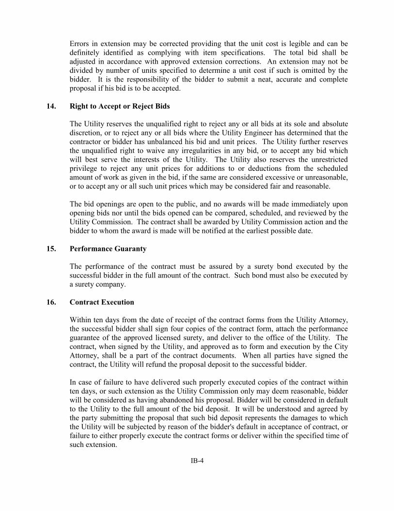
Errors in extension may be corrected providing that the unit cost is legible and can be definitely identified as complying with item specifications. The total bid shall be adjusted in accordance with approved extension corrections. An extension may not be divided by number of units specified to determine a unit cost if such is omitted by the bidder. It is the responsibility of the bidder to submit a neat, accurate and complete proposal if his bid is to be accepted.
14. Right to Accept or Reject Bids
The Utility reserves the unqualified right to reject any or all bids at its sole and absolute discretion, or to reject any or all bids where the Utility Engineer has determined that the contractor or bidder has unbalanced his bid and unit prices. The Utility further reserves the unqualified right to waive any irregularities in any bid, or to accept any bid which will best serve the interests of the Utility. The Utility also reserves the unrestricted privilege to reject any unit prices for additions to or deductions from the scheduled amount of work as given in the bid, if the same are considered excessive or unreasonable, or to accept any or all such unit prices which may be considered fair and reasonable.
The bid openings are open to the public, and no awards will be made immediately upon opening bids nor until the bids opened can be compared, scheduled, and reviewed by the Utility Commission. The contract shall be awarded by Utility Commission action and the bidder to whom the award is made will be notified at the earliest possible date.
15. Performance Guaranty
The performance of the contract must be assured by a surety bond executed by the successful bidder in the full amount of the contract. Such bond must also be executed by a surety company.
16. Contract Execution
Within ten days from the date of receipt of the contract forms from the Utility Attorney, the successful bidder shall sign four copies of the contract form, attach the performance guarantee of the approved licensed surety, and deliver to the office of the Utility. The contract, when signed by the Utility, and approved as to form and execution by the City Attorney, shall be a part of the contract documents. When all parties have signed the contract, the Utility will refund the proposal deposit to the successful bidder.
In case of failure to have delivered such properly executed copies of the contract within ten days, or such extension as the Utility Commission only may deem reasonable, bidder will be considered as having abandoned his proposal. Bidder will be considered in default to the Utility to the full amount of the bid deposit. It will be understood and agreed by the party submitting the proposal that such bid deposit represents the damages to which the Utility will be subjected by reason of the bidder's default in acceptance of contract, or failure to either properly execute the contract forms or deliver within the specified time of such extension.

IB-5
17. Starting Work Before Notification
No work shall be performed under the contract and no materials or equipment shall be delivered to the site of the work prior to the date in the Utility Engineer's written Notice to Proceed.
18. Refund of Bid Deposit to Unsuccessful Bidders
The bid deposit of all except the two lowest bidders will be refunded after the Utility Commission has determined the lowest responsible bidder. The remaining bid deposit will be refunded upon execution of the contract.

P-1
November 11, 2016 To: The Oak Creek Water & Sewer Utility Commission Re: Bid Proposal In conformity with the notice to bidders, the undersigned bidder, having examined the site of the work and the contract, submits the following proposal for furnishing the material, equipment, labor and everything necessary for the completion of the work listed hereunder, and agrees to execute the proposed contract and furnish the required bond for the completion of said work, at the locations and for the prices set forth in the attached Schedule One. The undersigned bidder deposits herewith a certified check payable to the order of the Oak Creek Water and Sewer Utility, or an approved bid bond, in the sum designated in said notice, and hereby agrees that in the event the undersigned bidder shall fail to execute the contract with surety bond thereto and return the same to the Utility within ten calendar days after transmittal by the Utility, then said certified check shall be retained by and become the property of the Oak Creek Water & Sewer Utility as fixed and liquidated damages or the penalty as provided by said bond shall be recovered as liquidated damages. It is further understood that construction on this contract shall commence and be completed as specified in the Detail Specifications. This proposal submitted by: _________________________________ ______________________________________ Bidder Address _________________________________ ____________________________________ Phone City, State, Zip Code Operating as: Sole Trader ______ Partnership ______ Corporation ______ Under the laws of the State of _____________________________ By: ___________________________________ (Signature)
___________________________________ (Title) ADDENDUM RECEIPT: We acknowledge the receipt of Addenda ___________ inclusive.

P-2
SWORN STATEMENT OF BIDDER PURSUANT TO SECTION 66.0901 (7) WISCONSIN STATUTES
I, being duly sworn at ________________________________________________(City), ______________________________ (State), on oath, do hereby state on behalf of said bidder that I have examined and carefully prepared this proposal from the plans, specifications, the work site including surface and underground conditions, and other contract documents and have checked the same in detail before submitting this proposal; and that this sworn statement is hereby made an integral part of this proposal. By: ___________________________________________
(Signature)
___________________________________________ (Title)
Subscribed and sworn to before me this ________ day of _________________, 2016. ________________________________________ Notary Public, ___________________________ County State of ______________________________________ My commission expires:__________________________ Affix corporate seal below.
P-3
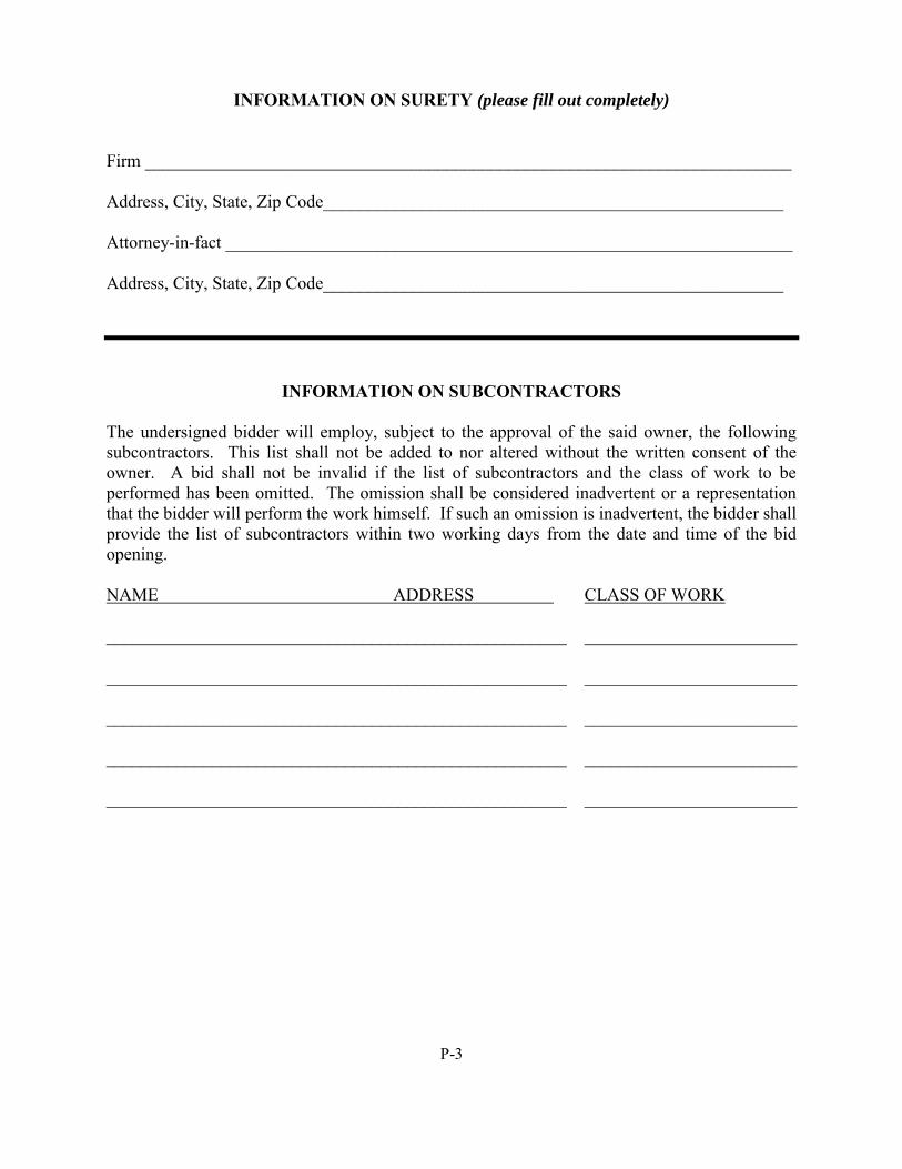
INFORMATION ON SURETY (please fill out completely) Firm _________________________________________________________________________ Address, City, State, Zip Code____________________________________________________ Attorney-in-fact ________________________________________________________________ Address, City, State, Zip Code____________________________________________________
INFORMATION ON SUBCONTRACTORS The undersigned bidder will employ, subject to the approval of the said owner, the following subcontractors. This list shall not be added to nor altered without the written consent of the owner. A bid shall not be invalid if the list of subcontractors and the class of work to be performed has been omitted. The omission shall be considered inadvertent or a representation that the bidder will perform the work himself. If such an omission is inadvertent, the bidder shall provide the list of subcontractors within two working days from the date and time of the bid opening. NAME ADDRESS CLASS OF WORK ____________________________________________________ ________________________ ____________________________________________________ ________________________ ____________________________________________________ ________________________ ____________________________________________________ ________________________ ____________________________________________________ ________________________
P-4
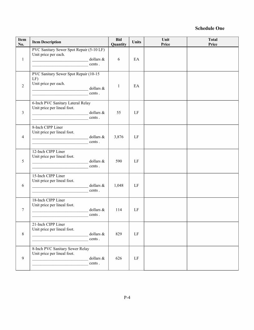
Schedule One
Item No. Item Description Bid
Quantity Units Unit Price
Total Price
1
PVC Sanitary Sewer Spot Repair (5-10 LF) Unit price per each. ___________________________ dollars & ___________________________ cents .
6 EA
2
PVC Sanitary Sewer Spot Repair (10-15 LF) Unit price per each. ___________________________ dollars & ___________________________ cents .
1 EA
3
6-Inch PVC Sanitary Lateral Relay Unit price per lineal foot. ___________________________ dollars & ___________________________ cents .
55 LF
4
8-Inch CIPP Liner Unit price per lineal foot. ___________________________ dollars & ___________________________ cents .
3,876 LF
5
12-Inch CIPP Liner Unit price per lineal foot. ___________________________ dollars & ___________________________ cents .
590 LF
6
15-Inch CIPP Liner Unit price per lineal foot. ___________________________ dollars & ___________________________ cents .
1,048 LF
7
18-Inch CIPP Liner Unit price per lineal foot. ___________________________ dollars & ___________________________ cents .
114 LF
8
21-Inch CIPP Liner Unit price per lineal foot. ___________________________ dollars & ___________________________ cents .
829 LF
9
8-Inch PVC Sanitary Sewer Relay Unit price per lineal foot. ___________________________ dollars & ___________________________ cents .
626 LF
P-5
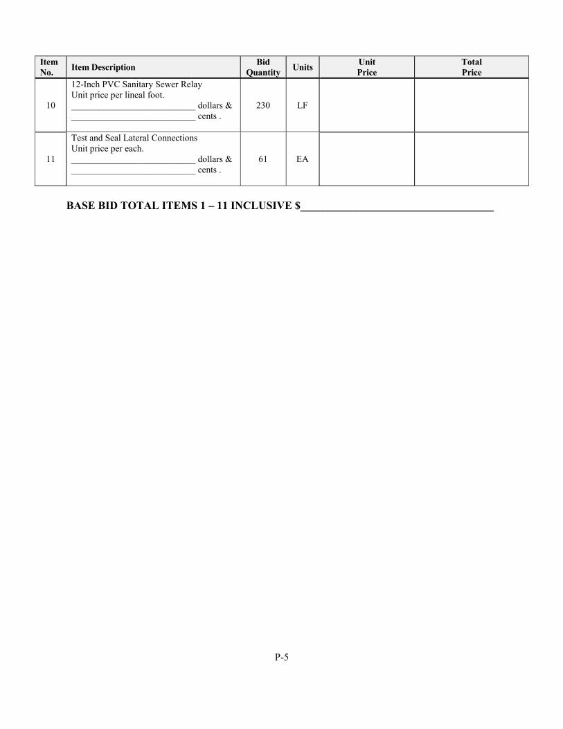
Item No. Item Description Bid
Quantity Units Unit Price
Total Price
10
12-Inch PVC Sanitary Sewer Relay Unit price per lineal foot. ___________________________ dollars & ___________________________ cents .
230 LF
11
Test and Seal Lateral Connections Unit price per each. ___________________________ dollars & ___________________________ cents .
61 EA
BASE BID TOTAL ITEMS 1 – 11 INCLUSIVE $___________________________________

DETAILED
SPECIFICATIONS
P.N. 16107 SECTION 01010 OCTOBER 2016 D-1 DESCRIPTION OF WORK
SECTION 01010
DESCRIPTION OF WORK PART 1 - GENERAL
The requirements of the Contract Documents, including the General Conditions, the Supplementary Conditions and Division I - General Requirements apply to this Section except as modified herein.
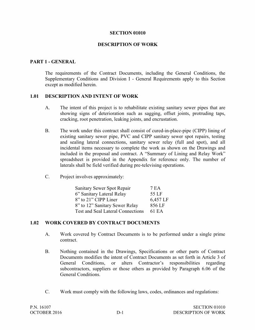
1.01 DESCRIPTION AND INTENT OF WORK
A. The intent of this project is to rehabilitate existing sanitary sewer pipes that are showing signs of deterioration such as sagging, offset joints, protruding taps, cracking, root penetration, leaking joints, and encrustation.
B. The work under this contract shall consist of cured-in-place-pipe (CIPP) lining of
existing sanitary sewer pipe, PVC and CIPP sanitary sewer spot repairs, testing and sealing lateral connections, sanitary sewer relay (full and spot), and all incidental items necessary to complete the work as shown on the Drawings and included in the proposal and contract. A “Summary of Lining and Relay Work” spreadsheet is provided in the Appendix for reference only. The number of laterals shall be field verified during pre-televising operations.
C. Project involves approximately:
Sanitary Sewer Spot Repair 7 EA 6” Sanitary Lateral Relay 55 LF 8” to 21” CIPP Liner 6,457 LF 8” to 12” Sanitary Sewer Relay 856 LF Test and Seal Lateral Connections 61 EA
1.02 WORK COVERED BY CONTRACT DOCUMENTS
A. Work covered by Contract Documents is to be performed under a single prime contract.
B. Nothing contained in the Drawings, Specifications or other parts of Contract
Documents modifies the intent of Contract Documents as set forth in Article 3 of General Conditions, or alters Contractor’s responsibilities regarding subcontractors, suppliers or those others as provided by Paragraph 6.06 of the General Conditions.
C. Work must comply with the following laws, codes, ordinances and regulations:
P.N. 16107 SECTION 01010 OCTOBER 2016 D-2 DESCRIPTION OF WORK
1. “Standard Specifications for Highway and Structure Construction,” State
of Wisconsin, Edition of 2016, and all Subsequent Supplemental Specifications, except Sections 101 through 109 and as may be modified by the Contract Documents, known as the “State Specifications”.
2. “Standard Specifications for Sewer and Water Construction in Wisconsin,” Sixth Edition dated December 22, 2003, including Addendum No. 1 and Addendum No. 2, except Part I – General Conditions, known as “Standard Specifications.”
3. State of Wisconsin Administrative Code and Wisconsin State Statutes.
4. Local Codes and Ordinances. Copies are on file at the Engineering
Department of the City of Oak Creek for use and reference on the premises.
5. The “Manual of Uniform Traffic Control Devices Latest Edition” shall
apply to all traffic control, signing, and barricading under this project with the exception that such specifications are modified and/or supplemented as set forth in these Specifications.
6. These Detailed Specifications and Drawings.
1.03 CONTRACTOR USE OF SITES
A. Confine operations at sites to areas permitted by:
1. Law.
2. Ordinances.
3. Permits.
4. Contract Documents.
B. Contractor shall assume full responsibility for protection and safekeeping of material and products stored on and off premises.
C. Contractor shall obtain and pay for use of additional storage or Work area if
needed for construction operations. D. Standard Hours for Performing Work:
1. During normal weekday working hours: 7:00 A.M. to 6:00 P.M. 2. During Saturdays: 8:00 A.M. to 5:00 P.M.
P.N. 16107 SECTION 01010 OCTOBER 2016 D-3 DESCRIPTION OF WORK
3. No Work shall be performed on Sundays or Holidays; however, emergency Work during these hours may be done without prior permission.
4. No Work shall be done outside of the standard hours unless otherwise approved by the Owner.
5. Work may extend beyond these hours because of cure time on larger diameter pipes. Verify acceptable working hours with Engineer prior to beginning work.
6. Check permit conditions for possible work hour restrictions on State and County Highways.
E. Construction activities shall only take place within the public right-of-way unless
otherwise noted on the Drawings or within these Special Provisions.
1.04 WORK SCHEDULE AND SEQUENCE
A. The Contractor shall complete the work in accordance with the schedule specified in the Agreement.
B. Contractor is responsible for establishing a schedule to be approved by the Owner for the sequence and progress of the Work that is designed to meet the completion date. Contractor shall be solely responsible for coordination of all Work to ensure completion of the Work within the time limits specified in these Contract Documents.
C. Repairs to damaged structures, if any, shall be completed within the same
calendar week in which the structure was damaged. D. All traffic control and erosion control devices shall be installed prior to
commencement of any Work.
E. When public interest necessitates, the Owner may determine the starting place and the work section sequence.
F. At least one lane of traffic must be maintained and open to through traffic at all
points in time. No road shall be closed without approval by the Engineer. G. It is the OWNER’s intent to complete all work, including restoration, in a
continuous manner, as quickly as possible, to minimize disruption and inconvenience to the public.
H. Substantial completion is defined as “such time as the sanitary sewer lining and
relays are completed to a point that surface restoration may be completed.”
P.N. 16107 SECTION 01010 OCTOBER 2016 D-4 DESCRIPTION OF WORK
I. The Contractor will not be permitted to start new phases of the project until previously started phases are fully completed or continuous work, in the opinion of the Utility Engineer, is being done to fully complete the previously started phases. However, the Contractor may with the approval of the Utility Engineer, start a second crew with a second foreman on other portions of the project. At any time during the execution of the contract that the Contractor either suspends or returns to work, he must notify the Utility Engineer of his intentions at least three working days in advance of said suspension or return to work.
1.05 FIELD VERIFICATION OF DRAWING INFORMATION
A. It is the responsibility of the Contractor to acquaint himself with the location of all
underground and overhead utilities and structures which may be encountered or which may be affected by Work under the contract. Where the construction is in an area serviced by an underground or overhead utility, the Contractor shall notify such service three (3) working days prior to commencing his operations.
B. The Contractor shall field verify site conditions, the size and location of existing
structures, equipment, and piping. Information on the Drawings is based upon available data at the time of preparation and is not guaranteed to be complete or correct.
1.06 SAFETY, HEALTH, AND SANITATION
A. The Contractor is responsible for safe work practices, including excavation, sheeting, and shoring; scaffolding; materials handling and drilling; safe operation of equipment; and safety of employees and other persons or organizations during progress of work on-site.
B. Work at the project site may place Contractor's personnel in potentially hazardous
situations due to Contractor's personnel's exposure to hazardous materials and hazardous conditions.
C. Contractor shall plan for and ensure personnel comply with the basic provisions
of OSHA Safety and Health Standards (29 CFR 1910), and General Construction Standards (29 CFR 1926), as applicable to specific tasks.
D. The Contractor shall comply with all Federal, State, and local laws governing
safety, health, and sanitation; shall provide all safeguards, safety devices, and protective equipment; shall be responsible for initiating, maintaining, and supervising all safety precautions; and shall take any other actions necessary to protect the life and health of employees on the job, the safety of the public, and property in connection with the performance of work on this project.
E. The Contractor shall meet the confined space requirements of the Wisconsin
Administrative Code.

P.N. 16107 SECTION 01010 OCTOBER 2016 D-5 DESCRIPTION OF WORK
F. The Contractor shall the secure the site by suitable protective methods which
include, but are not limited to barricades, signal lights, fences, or watch personnel. This shall be done in order to protect their work, persons, animals and property. The cost of this protection is incidental to the contract.
G. Contractor's duties and responsibilities for safety in connection with Work shall
continue until such time as all work is complete. H. The Contractor shall be responsible for the construction means, methods,
techniques or procedures, equipment, and for safety precautions or programs, unless such means and equipment are specified in these Contract Documents, utilized in the performance of work on this project. The Contractor shall comply with Section 108.7, Methods and Equipment, of the “State Specifications”.
1.07 MATERIALS - GENERAL
A. In accordance with Utility purchasing policy, the Contractor is requested to use American products in the performance of the contract whenever the quality and the price are comparable with other goods.
1.08 MATERIALS ENCOUNTERED
A. No variation from the price named in the proposal will be made or allowed whether the material through which excavations must be made are hard or soft, and wet or dry. It is the Contractor's responsibility to determine for himself the character, nature, type and condition of materials likely to be encountered in the proposed work. The submission of a proposal for the work herein shall in itself be accepted as evidence that the Contractor has examined the site of all work, made borings, investigations and studies of all conditions and provided for all such conditions in his proposal.
END OF SECTION

P.N. 16107 SECTION 01020 OCTOBER 2016 D-6 PROJECT SCHEDULE AND LIQUIDATED DAMAGES
SECTION 01020
PROJECT SCHEDULE AND LIQUIDATED DAMAGES PART 1 - GENERAL
The requirements of the Contract Documents, including the General Conditions, the Supplementary Conditions and Division I - General Requirements apply to this Section except as modified herein.
1.01 TIME OF COMPLETION
A. The starting date for work under this contract shall be at the discretion of the Contractor, subject to the following:
1. Preconstruction meeting as arranged by the Utility Engineer.
2. Issuance of the Notice to Proceed by the Utility Engineer.
3. Completion of the sanitary sewer rehabilitation and ready to use by May 19,
2017. 4. The entire project, including surface restoration shall be completed no later
than June 2, 2017.
B. It shall be understood by the Contractor that the date of starting construction and the date of completion of the work to be done hereunder are ESSENTIAL CONDITIONS of this con-tract, and it is further understood and agreed that the work shall be commenced as aforementioned.
C. The Contractor agrees that the work shall be pursued regularly, diligently, and
uninterruptedly at such rate of progress as will assure completion of the work on the dates as stated in the proposal.
1.02 EXTENSIONS OF TIME
A. Extensions of time may be allowed by the Utility for reasonable delays due exclusively to causes beyond the control and without the fault of the Contractor including but not restricted to owner purchased material delivery delays, extra work or supplemental contract work added to the original contract, fires, strikes, unusual floods, accidents and unreasonable delays in receiving ordered materials and equipment. It should be understood by the Contractor that rain events occur and fluctuate from year to year and shall not be considered cause for a time extensions.
B. All requests for extensions of time shall be presented in writing to the Utility
Engineer within ten calendar days after the occurrence of the claimed delay, accompanied by all necessary supporting data, and, if based on valid grounds will be
P.N. 16107 SECTION 01020 OCTOBER 2016 D-7 PROJECT SCHEDULE AND LIQUIDATED DAMAGES
considered by the Utility and such extensions of time shall be granted as may seem to be fair and reasonable. However, no claims will be considered when based on delays caused by conditions existing at the time bids were received and of which the Contractor might be reasonably expected to have knowledge at the time of bidding, or upon delays caused by failure on the part of the Contractor to anticipate properly the requirements of the work contracted for as to the securing of needed materials, labor and equipment.
1.03 LIQUIDATED DAMAGES
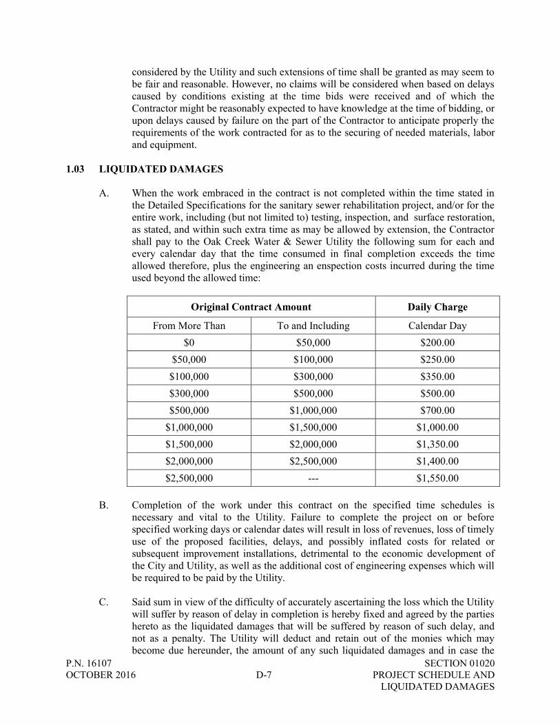
A. When the work embraced in the contract is not completed within the time stated in the Detailed Specifications for the sanitary sewer rehabilitation project, and/or for the entire work, including (but not limited to) testing, inspection, and surface restoration, as stated, and within such extra time as may be allowed by extension, the Contractor shall pay to the Oak Creek Water & Sewer Utility the following sum for each and every calendar day that the time consumed in final completion exceeds the time allowed therefore, plus the engineering an enspection costs incurred during the time used beyond the allowed time:
Original Contract Amount Daily Charge
From More Than To and Including Calendar Day $0 $50,000 $200.00
$50,000 $100,000 $250.00 $100,000 $300,000 $350.00 $300,000 $500,000 $500.00 $500,000 $1,000,000 $700.00
$1,000,000 $1,500,000 $1,000.00 $1,500,000 $2,000,000 $1,350.00 $2,000,000 $2,500,000 $1,400.00 $2,500,000 --- $1,550.00
B. Completion of the work under this contract on the specified time schedules is
necessary and vital to the Utility. Failure to complete the project on or before specified working days or calendar dates will result in loss of revenues, loss of timely use of the proposed facilities, delays, and possibly inflated costs for related or subsequent improvement installations, detrimental to the economic development of the City and Utility, as well as the additional cost of engineering expenses which will be required to be paid by the Utility.
C. Said sum in view of the difficulty of accurately ascertaining the loss which the Utility
will suffer by reason of delay in completion is hereby fixed and agreed by the parties hereto as the liquidated damages that will be suffered by reason of such delay, and not as a penalty. The Utility will deduct and retain out of the monies which may become due hereunder, the amount of any such liquidated damages and in case the

P.N. 16107 SECTION 01020 OCTOBER 2016 D-8 PROJECT SCHEDULE AND LIQUIDATED DAMAGES
amount which may become due hereunder shall be less than the amount of liquidated damages suffered, the Contractor shall be liable to pay the difference upon demand by the Utility.
END OF SECTION

P.N. 16107 SECTION 01040 OCTOBER 2016 D-9 COORDINATION
SECTION 01040
COORDINATION PART 1 - GENERAL
The requirements of the Contract Documents, including the General Conditions, the Supplementary Conditions and Division I - General Requirements apply to this Section, except as modified herein.
1.01 COOPERATION WITH OTHER CONTRACTORS
A. The Contractor shall work in harmony with other contractors, utilities, or Owner's forces engaged in collateral work. In case of dispute, the decision of the Engineer shall be final and binding upon the parties affected.
1.02 UTILITY PROTECTION
A. It shall be the responsibility of the Contractor to protect all utilities that are encountered in his work operations. The Contractor shall contact utilities to determine their procedure and schedule for resolving any conflicts. All costs of protecting existing utilities; such as tunneling, sheathing, bracing or relocation including utility company bracing and relocation charges, shall be considered incidental to utility construction.
1.03 UTILITY NOTIFICATION
A. The locations of utilities shown on the Drawings are from existing records and/or field locations and may not be complete or accurate.
B. The Contractor shall contact Digger’s Hotline at (800) 242-8511, as well as other utilities not served by Digger’s Hotline but having facilities in the work area, at least three (3) full business days prior to construction to notify the utilities to locate their underground facilities.
C. The Contractor has primary responsibility for coordinating their work with utilities after contract award and to resolve any conflicts that may exist. The Contractor shall communicate directly with the utilities regarding any utility work necessary to maintain the contractor’s schedule and prevent project construction delays. The contractor shall notify the residents of any issues.

P.N. 16107 SECTION 01040 OCTOBER 2016 D-10 COORDINATION
D. Utility Contacts. 1. Digger’s Hotline (800) 242-8511
a. WE Energies – Electric Operations 4800 W. Rawson Avenue Franklin, Wisconsin 53132 Phone: (414) 423-6112 in advance of construction
Phone: (414) 221-3700 during construction
b. WE Energies – Gas Operations
4800 W. Rawson Avenue Franklin, Wisconsin 53132 Phone: (414) 423-5062 in advance of construction Phone: (414) 221-3700 during construction
c. AT&T
Cable Location Point 435 S. 95th Street Milwaukee, Wisconsin (262) 896-7434
d. Time Warner Cable 5475 West Abbott Avenue Greenfield, Wisconsin 53220 (414) 277-4280
2. Oak Creek Water and Sewer Utility 170 West Drexel Avenue Oak Creek, Wisconsin 53154
Attn: Seth Ricker, Construction Coordinator (414) 570-8200, Ext. 38
3. City of Oak Creek Parks 800 W. Puetz Road Oak Creek, Wisconsin 53154 Attn: Jeffery Wendt (414) 570-5682
E. Please note: Section 66.0831 of Wisconsin Statutes makes it mandatory that:
"66.0831 Interference with public service structure. A contractor with a contract for work upon, over, along or under a public street or highway may not interfere with, destroy or disturb the structures of a public utility, including a telecommunications carrier as defined in s. 196.01 (8m), encountered in the performance of the work in a manner that interrupts,

P.N. 16107 SECTION 01040 OCTOBER 2016 D-11 COORDINATION
impairs or affects the public service for which the structures may be used, without first obtaining written authority from the commissioner of public works or other appropriate authority. A public utility, if given reasonable notice by the contractor of the need for temporary protection of, or a temporary change in, the utility's structures, determined by the commissioner of public works or other appropriate authority to be reasonably necessary to enable the work, shall temporarily protect or change its structures located upon, over, along or under the surface of a public street or highway. The contractor shall pay or assure to the public utility the reasonable cost of the temporary structure or change, unless the public utility is otherwise liable. If work is done by or for the state or by or for any county, city, village, town sanitary district, metropolitan sewerage district created under ss. 200.01 to 200.15 or 200.21 to 200.65 or town, the cost of the temporary protection or temporary change shall be borne by the public utility."
F. The Contractor shall refer to Chapter 1.2.0 (Pages 1-9) of the Standard Specifica-
tions, in regard to necessary notices and permits required. These provisions shall be strictly adhered to at the start of any part of the project.
1.04 NOTIFICATION TO CITY’S STREET, FIRE AND POLICE DEPARTMENTS, AND PUBLIC SCHOOLS
A. Prior to starting construction within any street, three (3) days’ written notice shall
be given to the following departments: 1. Street Division, 800 W. Puetz Road, (414) 768-6553 2. Fire Department, 7000 S. 6th Street, (414) 570-5630 3. Police Department, 301 W. Ryan Road, (414) 768-8200 4. Oak Creek Public Schools, 7630 South Tenth Street (414) 768-5880
1.05 HOMEOWNER AND BUSINESS NOTIFICATION
A. The Contractor shall notify all residents and businesses affected by this construction
at least 48 hours prior to any service disruption affecting their service connection. The Contractor shall make every effort to maintain service usage throughout the duration of the project. The Contractor may need to adjust their schedule to accommodate businesses that require a service connection during normal business hours. The contractor shall notify the residents of any issues.
1.06 COORDINATION OF WORK
A. The Contractor shall be responsible for the general coordination of the entire project. The Contractor shall be responsible to advise and coordinate the phases of Work with their subcontractors and their suppliers.
P.N. 16107 SECTION 01040 OCTOBER 2016 D-12 COORDINATION
1.07 NOTICE OF INTENT TO START WORK
A. Contractor shall notify all appropriate governmental and regulatory units, including emergency services departments, at least three (3) working days prior to his commencing operations of his intent to start Work.
B. Contractor shall notify the Owner, the Engineer, and all utilities and/or underground
facilities locators whose property may be affected by the Contractor's operations at least three (3) working days prior to his commencing operations of his intent to start Work. Continuing notice shall be given to the Owner each time construction is resumed after shutdown.
1.08 EXISTING CONDITIONS – CCTV REVIEW
A. Televising of the Utility’s sanitary sewer main was completed on various dates by the Utility. This information is available upon request, 48 hours notice, and $20 refundable deposit. Videos will be in the form of a flash drive to be picked up at the Oak Creek Water and Sewer Utility, 170 W. Drexel Avenue, Oak Creek, Wisconsin, 53154.
B. Failure of the Contractor to review the available data prior to the time of bidding
shall not constitute grounds for a change order during construction. C. If the existing conditions video reveals conditions substantially different than those
used in the design of the wall thickness, tube construction, tube length, and resin system, the Contracor shall advise the Engineer. No work shall be completed until written clarification is provided by the Engineer.
1.09 WORK IN EASEMENTS
A. The work will be performed in an easement or by right-of-entry upon private lands. The requirements of Sections 1.7.13 and 1.7.14 (Pages 1-35 and 1-36) of the Standard Specifications and these detailed specifications, if any, shall be adhered to.
B. The requirements of Section 1.7.14 of such Standard Specifications shall also apply
to the public right-of-way between the pavement and the property line where the installation is in the public right-of-way or in an easement abutting public right-of-way.
END OF SECTION

P.N. 16107 SECTION 01045 OCTOBER 2016 D-13 CONTRACTOR’S INSURANCE, BOND REQUIREMENTS, AND PAYMENT METHOD
SECTION 01045
CONTRACTOR’S INSURANCE, BOND REQUIREMENTS, AND PAYMENT METHOD
1.01 GENERAL
A. The Contractor shall not commence work under this contract until he has obtained all
insurance required under this paragraph and such insurance has been approved by the Utility and insurance certificates have been filed with the Utility, nor shall the Contractor allow any Subcontractor to commence work on his subcontract until all similar insurance required of the Subcontractor has been so obtained and approved in accordance with Section 1.8.4 of the Standard Specifications and these Detailed Specification provisions.
1.02 COMPENSATION INSURANCE
A. The Contractor shall take out and maintain during the life of this contract, Worker's Compensation Insurance for all of his employees at the site of the project and in case any work is sublet, the Contractor shall require the Subcontractor similarly to provide Worker's Compensation Insurance for all of the latter's employees, unless such employees are covered by the protection afforded by the Contractor. In case any class of employees engaged in hazardous work under this contract at the site of the project is not protected under the Worker's Compensation Statute, the Contractor shall provide and shall cause each Subcontractor to provide adequate insurance coverage for the protection of his employees not otherwise protected.
1.03 PUBLIC LIABILITY, PROPERTY DAMAGE, AND CONTRACTUAL LIABILITY
INSURANCE A. The Contractor shall take out and maintain during the life of this contract, public
liability, property damage, and contractual liability insurance in the following minimum amounts:
1. Bodily Injury $1,000,000 per occurrence $1,000,000 aggregate
2. Property Damage $500,000 per occurrence $500,000 aggregate B. These policies shall protect the Contractor and any Subcontractor performing work
covered by this contract from the claims and damages for personal injury, including accidental death, as well as claims for property damage, which may arise from the performance of the work or under the hold-harmless and indemnifying clauses which are a part of this contract. The said policies are to cover not only the Contractor or

P.N. 16107 SECTION 01045 OCTOBER 2016 D-14 CONTRACTOR’S INSURANCE, BOND REQUIREMENTS, AND PAYMENT METHOD
Subcontractor but also any other directly or indirectly employed by either of them.
1.04 INSURANCE AGAINST THE FOLLOWING SPECIAL HAZARDS
A. The following respective amounts shall be procured by the Contractor or Subcontractor before the commencement of any operation by the Contractor, or the happening of any circumstance creating or tending to create the particular special hazard:
Kind Amount Operating of elevators or hoists....................................................................$25,000.00 Use and operation of automobiles and truck................................................$25,000.00 Structural alterations or demolitions ............................................................$25,000.00 Undermining adjacent structures..................................................................$10,000.00 Blasting operations .......................................................................................$10,000.00 Operation of excavating machinery in streets and highways.......................$10,000.00 Operation within other public or private right-of-way (including railroad right-of-way) .................................................................................As Required
1.05 PERFORMANCE BOND AND GUARANTEE
A. Where the contract is over $10,000.00, the contractor will be required to furnish a satisfactory performance bond in the amount of 100% of the contract. The Contractor shall pay the total cost of this bond. Such bond shall be executed by an authorized surety company and shall remain in full force and effect for a period of one year after the final payment for the work to guarantee workmanship and materials. A performance bond shall not be required for public works contracts below $10,000.00 regardless of bond requirement.
B. The Contractor shall agree and guarantee that the material and workmanship supplied
by him shall be free from all defects, and strictly in accordance with the plans and specifications, at the time of its completion and acceptance by the municipality, and for a time of one year thereafter, the Contractor agrees to forthwith repair the same upon notification by the municipality using the same material required by these specifications. In case the Contractor shall fail to make such repairs or cause the same to be made, the Contractor agrees and guarantees to pay on demand the cost thereof, to said municipality upon the completion of such repairs, and the Contractor further agrees and guarantees to pay for all labor and material used in or about the construction of said work in his contract, which may become a lien or a claim against the municipality.
1.06 METHOD OF PAYMENTS
A. Payments will normally be made monthly throughout the progress of the work,
provided the work completed is substantial enough in the opinion of the Utility
P.N. 16107 SECTION 01045 OCTOBER 2016 D-15 CONTRACTOR’S INSURANCE, BOND REQUIREMENTS, AND PAYMENT METHOD
Engineer. B. Substantial completion of water main construction shall be considered to include all
flushing and testing of the mains including pressure tests and safe water samples. Partial and final payments will not be made until such time that all work is substantially completed including testing and accepted by the approving agencies.
C. Such payments shall be in accord with Section 66.0901 (9) b, of the State Statutes
which states that the City,
“(b) Retained percentages. As the work progresses under a contract involving $1,000 or more for the construction, execution, repair, remodeling or improvement of a public work or building or for the furnishing of supplies or materials, regardless of whether proposals for the contract are required to be advertised by law, the municipality, from time to time, shall grant to the contractor an estimate of the amount and proportionate value of the work done, which entitles the contractor to receive the amount of the estimate, less the retainage, from the proper fund. The retainage shall be an amount equal to not more than 5% of the estimate until 50% of the work has been completed. At 50% completion, further partial payments shall be made in full to the contractor and no additional amounts may be retained unless the architect or engineer certifies that the job is not proceeding satisfactorily, but amounts previously retained shall not be paid to the contractor. At 50% completion or any time after 50% completion when the progress of the work is not satisfactory, additional amounts may be retained but the total retainage may not be more than 10% of the value of the work completed. Upon substantial completion of the work, an amount retained may be paid to the contractor. When the work has been substantially completed except for work which cannot be completed because of weather conditions, lack of materials or other reasons which in the judgment of the municipality are valid reasons for noncompletion, the municipality may make additional payments, retaining at all times an amount sufficient to cover the estimated cost of the work still to be completed or may pay out the entire amount retained and receive from the contractor guarantees in the form of a bond or other collateral sufficient to ensure completion of the job. For the purposes of this section, estimates may include any fabricated or manufactured materials and components specified, previously paid for by the contractor and delivered to the work or properly stored and suitable for incorporation in the work embraced in the contract. "
END OF SECTION
P.N. 16107 SECTION 01050 OCTOBER 2016 D-16 FIELD ENGINEERING
SECTION 01050
FIELD ENGINEERING PART 1 - GENERAL The requirements of the Contract Documents, including the General Conditions, the
Supplementary Conditions and Division I - General Requirements apply to this Section except as modified herein.
1.01 SURVEYING AND STAKING
A. The Contractor shall be responsible for all lines, elevations and measurements of all Work executed under the Contract. Contractor must exercise proper precaution to verify figures before laying out Work and will be held responsible for any error resulting from their failure to exercise such precaution.
B. If staking is requested, Contractor shall submit for consideration or retain their own
forces at Contractor’s cost. Contractor shall give at least 48 hours’ notice to Engineer to request staking, take measurements, check grades and inspect items of Work.
C. The Contractor must protect all stakes and benchmarks from disturbances until
permission is given to remove them. A width of not less than 2' on each side of the line on which stakes are located shall be kept free from obstruction. Additional staking required due to damage or removal shall be at the Contractor's expense.
1.02 CONSTRUCTION MONITORING
A. The Contractor shall comply with the specifications and ably perform all operations to the extent that the first-class work will be obtained. A representative of the Oak Creek Water & Sewer Utility will inspect the work as it progresses to determine full compliance with the specifications. The Inspector shall notify the Utility Engineer of any noncompliance and have authority to stop any work not being performed in accordance with the specifications, in order that an Engineer may investigate such noncompliance.
B. Any work performed after the work has been ordered stopped by the Inspector shall
not be considered as work performed under the contract, and consequently will not be accepted by the Utility nor allowed in any monthly or final payment until corrected to the satisfaction of the Utility Engineer.
C. The "Standard Specifications for Sewer and Water Construction in Wisconsin",
(herein referred to as The Standard Specifications), shall apply for all sewer and water main construction unless otherwise noted in these Detail Specifications or on the construction plans. The Highway and Structure Construction - Standard Specifications Department of Transportation, Division of Highways, State of Wisconsin and
P.N. 16107 SECTION 01050 OCTOBER 2016 D-17 FIELD ENGINEERING
Supplemental Specifications (herein referred to as the State Specifications), shall apply for pavement restoration. The MUTCD and State Specifications shall apply to all traffic control.
D. All services rendered by the Engineer will consist of professional opinions and
recommendations in accordance with the generally accepted construction engineering practices. Under no circumstances is it the intent of the Engineer’s representative to directly control the physical activities of the Contractor’s or subcontractor’s accomplishment of Work on this project. The purpose of the Engineer’s representative at the site is to provide observation and monitoring of the Contractor's Work, and does not include any superintending, supervising or direction of the actual Work.
END OF SECTION

P.N. 16107 SECTION 01060 OCTOBER 2016 D-18 REGULATORY REQUIREMENTS
SECTION 01060
REGULATORY REQUIREMENTS PART 1 - GENERAL The requirements of the Contract Documents, including the General Conditions, the
Supplementary Conditions and Division I - General Requirements apply to this Section except as modified herein.
1.01 PERMITS, EASEMENTS, AND LICENSES
A. The Contractor shall procure all necessary permits and easements, pay all charges and fees and give all notices necessary and incidental to the due and lawful prosecution of the Work.
B. All Work requiring permits or easements shall abide by the governing
permit/easement specifications where they exceed the requirements stated in these specifications.
C. All required permits, easements, and/or local, state, and federal permits must be
obtained prior to construction commencement. D. Known permits and approvals required for this project are specified below.
1. City of Oak Creek Public Right-of-Way Excavation Permit.
E. Possible permits and licenses for this project are specified below.
1. A fill permit is required if surplus excavated material and/or removed pavement
is placed within the City of Oak Creek outside of the project limits. If disposing material outside of the City’s municipal boundary, the Contractor shall obtain necessary local and state land disturbance and grading permits. The Contractor shall supply the Engineer with the location(s) of disposal sites.
2. Construction Pit Dewatering Discharge Permit.
a. Any and all necessary dewatering shall be in accordance with Chapter
2.2.13 of the Standard Specifications.
b. The Contractor shall also comply with the provisions of Chapter 283.35, Wisconsin Statutes, regulating the discharge of effluent from construction pit (trench) dewatering. These provisions provide for the removal of suspended solids from dewatering effluent prior to the direct discharge to surface waters or wetlands.

P.N. 16107 SECTION 01060 OCTOBER 2016 D-19 REGULATORY REQUIREMENTS
c. The Contractor shall apply to the Department of Natural Resources for a permit to discharge effluent from construction pit dewatering. This discharge may be covered by an existing General Permit for discharging Contaminated Storm Water Runoff/Or construction Pit Dewatering. Application forms for this permit(s) may be obtained at:
http://dnr.wi.gov/topic/wastewater/GeneralPermits.html 1.02 COMPLIANCE WITH LAWS
A. The Contractor, his agents and employees, shall at all times observe and comply with all Federal and State Laws, local laws, ordinances, codes and regulations which in any manner affect the conduct of the Work and all such orders or decrees as exist at the present and which may be enacted later, of bodies or tribunals having jurisdiction or authority over the Work. Contractor shall protect and hold harmless the Owner, the Engineer and their representatives, against any claim or liability arising from the violation of any such law, ordinance, code, regulation or order.
B. In particular, Contractor shall comply with all local ordinances regulating noise
levels, dust, mud, roadway load limits and barricades/warning devices required at the site.
1.03 CONSTRUCTION MEANS, METHODS, SAFETY, ETC…
A. The Contractor shall be responsible for compliance with all Federal, State and local laws including OSHA Standards, and with any other applicable laws, ordinances, rules regulations and orders of any public body having jurisdiction for the safety of persons or property or to protect them from damage, injury or loss. The Contractor shall provide all safeguards, safety devices and protective equipment and shall be responsible for initiating, maintaining and supervising all safety precautions and programs utilized by the Contractor and his sub-contractors in the performance of their work and shall take any other actions necessary to protect the life and health of employees on the job and safety of the public and to protect property in connection with the performance of work on this project.
B. The Contractor shall be responsible for the construction means, methods,
techniques or procedures, equipment, and for safety precautions or programs, unless such means and equipment are specified in these Contract Documents, utilized in the performance of work on this project. The Contractor shall comply with Section 108.5, Equipment, Methods and Materials, of the “State Specifications”.
1.04 POLLUTION CONTROL
A. Observe Laws and Regulations for environmental pollution and protection of environment. Do not pollute any wetland, lake, river, stream or other watercourse by dumping refuse, rubbish, debris or dredged material therein.

P.N. 16107 SECTION 01060 OCTOBER 2016 D-20 REGULATORY REQUIREMENTS
B. Protect sewers. Prevent construction materials, earth and debris from entering
facilities. C. Prevent contamination and the impairment of existing potable water facilities and
piping both public and private. D. Legally dispose of surplus excavated material and other waste material resulting
from work. Make arrangements and pay costs in connection with disposal of such materials. Do not burn material or trash on site.
1.05 EROSION CONTROL AND GROUND COVER
A. Pursuant to City of Oak Creek Code, construction activities are required to comply with erosion control and ground cover requirements. For public works construction, specifically, the following construction activity requirements are applicable.
1. Those involving grading, removal of protective ground cover or vegetation,
excavation, landfilling or other land disturbing activity affecting a surface area of 4,000 square feet or more;
2. Those involving excavation or filling or a combination of excavation and
filling affecting 400 cubic yards or more of dirt, sand or other excavation or fill material;
3. Those involving street, highway, road, or bridge construction, enlargement,
relocation or reconstruction; 4. Those involving the laying, repairing, replacing or enlarging of an
underground pipe facility for a distance of 300' or more.
B. To address the requirements, the Contractor shall provide for the implementation of the control measures as may be needed.
1.06 DISTRIBUTION OF EXCESS EXCAVATED MATERIAL
A. The disposal of all surplus excavated materials shall be the responsibility of the Contractor, shall be at the Contractor's expense and if disposed of within the limits of the City of Oak Creek, shall comply with the following regulations. The Contractor prior to the start of construction shall indicate the location at which the surplus excavated material will be disposed of.
B. The placement of fill on private lands located in the City of Oak Creek is under City
regulation, in accordance with the Municipal Code. The disposal of surplus excavated materials, including that derived from public works construction, is subject to compliance with this code. Basically, the Code provides for only the following forms of landfilling:
P.N. 16107 SECTION 01060 OCTOBER 2016 D-21 REGULATORY REQUIREMENTS
1. When the fill comprises of less than 1,000 cubic yards and is to be placed on a parcel of land of one acre or less in size. An application shall be made to the City Engineer for a permit, on a one-time-only basis. A $300.00 fee, plus an applicable erosion control permit and fee, is required.
2. Shoreline erosion control, whereby a license must be applied for and granted
prior to landfilling activity being undertaken. 3. On a site, where fill may be needed in conjunction with building construction
and where a building permit is in effect. 4. On City-owned property, subject to plans approved by the Common Council. 5. On a site where a landfill license is in effect.
END OF SECTION
P.N. 16107 SECTION 01200 OCTOBER 2016 D-22 PROJECT MEETINGS
SECTION 01150
MEASUREMENT AND PAYMENT PART 1 - GENERAL 1.01 DESCRIPTION
A. The items listed below beginning with Paragraph 1.05, correspond to and are the same pay items listed in the Bid Schedule. They constitute all of the pay items for the completion of the Work. No direct or separate payment will be made for mobilization, providing miscellaneous temporary or accessory works, services, field offices, job signs, sanitary requirements, dewatering, testing, safety devices, water supplies, power, maintaining traffic, bonds, insurance and all other requirements of the General Conditions and Supplementary Conditions.
B. The total Contract Amount shall cover the Work required by the Contract
Documents. All costs in connection with the successful completion of the Work, including furnishing all materials, equipment, supplies, and appurtenances; providing all construction, equipment, and tools; and performing all necessary labor and supervision to fully complete the Work, shall be included in the unit prices bid. All Work not specifically set forth as a pay item in the Bid Form shall be considered a subsidiary obligation of the Contractor and all costs in connection therewith shall be included in the prices bid.
C. The unit prices listed in the Bid Schedule shall include all services, obligations,
responsibilities, labor, materials, devices, equipment, royalties and license fees, supervision, temporary facilities, construction equipment, bonds, insurance, taxes, clean up, erosion control, traffic control, control surveys, field offices, close out, overhead and profit and all connections, appurtenances and any other incidental items of any kind or nature, as are necessary to complete the Work in accordance with the Contract Documents.
D. All schedules and inventories included in the Contract Documents are given for
convenience and are not guaranteed to be complete. The Contractor shall assume all responsibility for the making of estimates of the size, kind, and quantity of materials and equipment included in work to be done under this Contract.
E. Where pipe fittings and connections are noted on the Drawings, such notation is
for the Contractor's convenience and does not relieve the Contractor from laying and jointing different or additional items where required.
1.02 ENGINEER’S ESTIMATE OF QUANTITIES
A. Engineer’s estimated quantities for unit price pay items, as listed in the Bid Schedule, are approximate only and are included solely for the purpose of
P.N. 16107 SECTION 01200 OCTOBER 2016 D-23 PROJECT MEETINGS
comparison of Bids. The Bid Schedule does not expressly or by implication agree that the nature of the materials encountered below the surface of the ground or the actual quantities of material encountered or required will correspond therewith and Owner reserves the right to increase or decrease any quantity or to eliminate any quantity as the Owner may deem necessary. Contractor will not be entitled to any adjustment in a unit bid price as a result of any change in an estimated quantity and agrees to accept the aforesaid unit bid prices as complete and total compensation for any additions or deductions caused by a variation in quantities as a result of more accurate measurement, or by any changes or alterations in the Work ordered by the Bid Schedule, and for use in the computation of the value of the Work performed for progress payments.
1.03 WORK NOT PAID FOR SEPARATELY
A. Delivery: Payment for equipment delivery, storage or freight shall be included in the pay items including their installation and no other separate payment will be made therefore.
B. Bonds: Payment for bonds required by the Contract shall be included in the pay
items for the Work covered by the required bonds and no separate payment will be made.
C. Preparation of Site: Unless specified otherwise, payment for preparation of site
shall be included in pay items proposed for the various items of Work and no separate payment will be made therefore. Preparation of site includes temporary erosion control, traffic control, setting up equipment and storage areas, sanitary and other facilities required by the specifications or state law or regulations; providing access to the site; obtaining necessary permits and licenses; payments of fees; general protection, temporary heat and utilities including electrical power; providing shop and working drawings, certificates and schedules; providing required insurance; preconstruction photographs and videos; trench excavation, sheeting, shoring and bracing; dewatering and disposal of surplus water; pipe insulation; structural fill, backfill, compaction and grading; disposal of excess excavated material; testing materials and apparatus; close-out documentation; cleaning up; restoration of Contractor storage areas; disposal of trash and rubbish, demobilization, and any other post-construction work necessary for the proper conclusion of the Work and all other work regardless of its nature which may not be specifically referred to in a Bid Item but is necessary for the complete construction of the project set forth by the Contract.
D. Permit Conditions: Payment for work and fees required to comply with permits
shall be included in other pay items unless otherwise specified in Section 1.05 below.

P.N. 16107 SECTION 01200 OCTOBER 2016 D-24 PROJECT MEETINGS
1.04 MEASUREMENT FOR PAYMENT
A. Methods of Measurement - Generally:
1. Units of measurement shall be defined in general terms as follows:
a. Linear Feet (LF) b. Each (EA)
2. Unit Price Contracts/Items:
a. Linear Feet (LF) shall be measured along the horizontal length of the centerline of the installed material, unless otherwise specified. Pipe shall be measured along the length of the completed pipeline, regardless of the type of joint required.
c. Each (EA) shall be measured as the amount of the unit of measure
installed within the limits specified and shown in the Specifications and Drawings. Contractor shall provide supporting documentation to verify actual installed quantities.
1.05 CONTRACT BID ITEMS
A. ITEM NO. 1 AND ITEM NO. 2: PVC SANITARY SEWER SPOT REPAIR, 5-10 LF AND 10-15 LF 1. Description: The bid item for PVC Sanitary Sewer Spot Repair shall include
labor, materials, tools, and equipment needed to excavate, remove and dispose of the existing defective sanitary sewer pipe section(s), and relay with new sanitary sewer pipe as specified. This bid item includes all mobilization, saw-cutting pavement, removing and disposing pavement, excavation, sheeting, shoring and bracing, diking, bailing, draining, well pointing and dewatering; the protection of existing utilities and structures; removing and disposing pipes; abandoning inactive laterals, wyes, and tees; inspecting lines; furnishing and installing new sewer pipe; the furnishing and placing of bedding materials; the furnishing and placing of all new sewer pipe, wye fittings, and joint materials; all work necessary for the water tight reconnection to existing sanitary sewer main, laterals, and manholes; televising; testing; all backfilling including the furnishing, placing and compacting of granular backfill in all excavations made for sewer construction; all pavement and other surface restoration required; and all other work required for complete sanitary sewer installation.
2. Measurement: PVC Sanitary Sewer Spot Repair shall be measured per each 5-
10 LF and 10-15 LF section of PVC sanitary sewer repaired.

P.N. 16107 SECTION 01200 OCTOBER 2016 D-25 PROJECT MEETINGS
3. Payment: At the contract unit price for each 5-10 LF and 10-15 LF section of
PVC Sanitary Sewer Spot Repair as measured. B. ITEM NO. 3: PVC SANITARY LATERAL RELAY, 6-INCH
1. Description: The bid item for PVC Sanitary Lateral Relay shall include labor, materials, tools, and equipment needed to excavate, remove and dispose of the existing defective sanitary lateral pipe section(s), and relay with new sanitary lateral pipe as specified. This bid item includes all mobilization, saw-cutting pavement, removing and disposing pavement, excavation, sheeting, shoring and bracing, diking, bailing, draining, well pointing and dewatering; the protection of existing utilities and structures; removing and disposing pipes; inspecting lines; the furnishing and placing of bedding materials; the furnishing and placing of all new sewer pipe, wye fittings, and joint materials; all work necessary for the water tight reconnection to existing sanitary sewer main and manholes; televising; testing; all backfilling including the furnishing, placing and compacting of granular backfill in all excavations made for sewer construction; all pavement and other surface restoration required (including concrete appurtenances and lawn restoration); and all other work required for complete sanitary lateral installation.
2. Measurement: PVC Sanitary Lateral Relay shall be measured along the length of the new sanitary lateral.
3. Payment: At the contract unit price per lineal foot of PVC Sanitary Lateral Relay as measured.
C. ITEM NO. 4 THROUGH ITEM NO. 8: CIPP LINER, 8-INCH THROUGH 21-
INCH
1. Description: The bid item for CIPP Liner shall include all materials, equipment, tools, labor, preparation, installation, cleaning, pre and post construction televising in NASSCO PACP standard file structure, mobilization and demobilization, water use, service lateral reinstatements; all work required for the submittal of the Performance Work Statement, product data, the Safety Plan, the Quality Control Plan, and As-Built Drawings; sampling and testing, and all quality assurance for this item as specified. This bid item shall also include removal and disposal of debris from sewer line prior to installation. Debris removal includes mineral deposits, roots, and other debris.
2. Measurement: CIPP Liner shall be measured along the length of the sanitary sewer main from center of manhole to center of manhole for each size of sewer lined.

P.N. 16107 SECTION 01200 OCTOBER 2016 D-26 PROJECT MEETINGS
3. Payment: At the contract unit price per lineal foot of each size of CIPP Liner as measured.
D. ITEM NO. 9 AND ITEM NO. 10: PVC SANITARY SEWER RELAY, 8-INCH
AND 12-INCH
1. Description: The bid item for PVC Sanitary Sewer Relay shall include labor, materials, tools, and equipment needed to excavate, remove and dispose of the existing defective sanitary sewer pipe section(s), and relay with new sanitary sewer pipe as specified. This bid item includes all mobilization, saw-cutting pavement, removing and disposing pavement, excavation, sheeting, shoring and bracing, diking, bailing, draining, well pointing and dewatering; the protection of existing utilities and structures; removing and disposing pipes; abandoning inactive laterals, wyes, and tees; inspecting lines; furnishing and installing new sewer pipe; the furnishing and placing of bedding materials; the furnishing and placing of all new sewer pipe, wye fittings, and joint materials; all work necessary for the water tight reconnection to existing sanitary sewer main, laterals, and manholes; televising; testing; all backfilling including the furnishing, placing and compacting of granular backfill in all excavations made for sewer construction; all pavement and other surface restoration required (including concrete appurtenances and lawn restoration); and all other work required for complete sanitary sewer installation.
2. Measurement: PVC Sanitary Sewer Relay shall be measured along the length of the new sanitary sewer main for each size of sewer pipe relayed.
3. Payment: At the contract unit price per lineal foot of PVC Sanitary Sewer Relay for each size of sewer relayed as measured.
E. ITEM NO. 11: TEST AND SEAL LATERAL CONNECTIONS
1. Description: The bid item for test and seal lateral connection shall include all
materials, equipment, tools, and labor necessary to complete all work as specified. Cleaning and re-testing lateral connections shall be considered incidental to the Work.
2. Measurement: Test and Seal Lateral Connections shall be measured per each lateral connection successfully tested and sealed.
3. Payment: At the contract unit price for each lateral successfully tested and sealed as measured.
END OF SECTION

P.N. 16107 SECTION 01200 OCTOBER 2016 D-27 PROJECT MEETINGS
SECTION 01200
PROJECT MEETINGS
PART 1 - GENERAL The requirements of the Contract Documents, including the General Conditions, the
Supplementary Conditions and Division I - General Requirements apply to this Section except as modified herein.
1.01 PRECONSTRUCTION MEETING
A preconstruction conference shall be held after the time of the contract award and before the notice to proceed to discuss the responsibility of each party in the project and to clarify any questions. A representative of the resident inspection staff shall preside over the conference. A. The Contractor, subcontractors, and utility and railroad representatives shall attend
a preconstruction meeting at the Utility prior to commencing work on the site. The Contractor will be advised of the exact date, time and location of the meeting by the Engineer, and will be moderated by the Engineer.
B. The meeting shall be attended by someone having the authority to make informed
commitments for the Contractor.
C. The agenda will include, but not be limited to:
1. Review of bonds and insurance certificates.
2. Submission of list of Subcontractors, list of products, proposed construction schedule, traffic control plan, erosion control plan, equipment and material storage plan, and emergency contact list.
3. Designation of personnel representing the parties in Contract and the
Engineer.
4. Procedures and processing of field decisions, submittals, and substitutions, applications for payments, proposal request, Change Orders and Contract closeout procedures.
5. Tentative construction schedule setting out target dates for completion of
key elements.
6. Use of premises by Owner and Contractor.
P.N. 16107 SECTION 01200 OCTOBER 2016 D-28 PROJECT MEETINGS
7. Security and housekeeping procedures.
8. Procedures for maintaining record documents.
9. Liquidated damages.
10. Project safety.
11. Project coordination meeting schedule.
12. Location(s) of the Contractor’s material storage points.
13. Name of the foreman who will be staffing the project for the Contractor, and a name and telephone number of a 24-hour contact in case of an after-hours emergency
1.02 COORDINATION MEETINGS
A. The Contractor shall attend project coordination meetings, which shall be held throughout the progress of the work at intervals set during the preconstruction conference. There are no pre-planned coordination meetings scheduled.
B. Project meetings shall be attended by all contractors and major subcontractors.
The purpose of the meetings will be to coordinate work schedule, review the project progress and address any other matters that may need to be discussed.
C. A suggested agenda would include but not be limited to the following subjects:
1. Review of work progress. 2. Review of submittals schedule and status of submittals. 3. Maintenance of progress schedule. 4. Other business.
1.03 FINAL WALK THROUGH
A. The Contractor shall schedule final walk through with the Engineer and Owner at the site upon substantial completion and also upon final completion.
B. Interim walk-throughs should be scheduled at key points in the construction
process.
END OF SECTION

P.N. 16107 SECTION 01210 OCTOBER 2016 D-29 ALLOWANCES
SECTION 01210
ALLOWANCES PART 1 - GENERAL The requirements of the Contract Documents, including the General Conditions, the
Supplementary Conditions and Division I - General Requirements apply to this Section except as modified herein.
1.01 EXAMINATION OF SITE A. The contractor, prior to submitting this proposal, shall visit the site of the said work
and familiarize himself with the location and conditions affecting the work thereon and/or therein. No allowance will be granted because of lack of knowledge of such conditions.
B. The Contractor shall take photographs and/or videos of the project area prior to
beginning Work for restoration purposes. 1.02 INCIDENTAL WORK A. Incidental work shall include all work not particularly specified or that which may
be specified and not provided for in a basis for payment, that is of an incidental or temporary nature, and required in order to safely and satisfactorily carry out the intent of the work as indicated on the drawings and in the specifications. The cost of such work shall be merged with and included in the prices bid under all items of work.
1.03 BID ALLOWANCES A. It is understood that the Contractor has included in the Contract Price all allowances
so named in the Contract Documents and shall cause the Work so covered to be furnished and performed for such sums as may be acceptable to Owner and Engineer. Contractor agrees that: 1. The unit price for extras and credits includes all costs for materials and
installation, complete, and ready for use by Owner. 2. Prior to final payment, an appropriate Change Order will be issued as
recommended by Engineer to reflect actual quantities and amounts due Contractor according to the Unit Price Schedule. The Contract Price shall be correspondingly adjusted.
END OF SECTION
P.N. 16107 SECTION 01300 OCTOBER 2016 D-30 SUBMITTALS
SECTION 01300
SUBMITTALS PART 1 - GENERAL The requirements of the Contract Documents, including the General Conditions, the
Supplementary Conditions and Division I - General Requirements apply to this Section except as modified herein.
1.01 PRODUCT SUBMITTALS
A. Submit information requested under each specific section where applicable.
B. Contractor shall submit copy to the Engineer for review and approval. The Contractor shall not proceed until the Owner’s approval is given.
C. In the event a substitution is approved, the Owner will require from the Contractor a
credited deduction from the Contract amount equal to any savings in material cost resulting from use of the proposed substitute.
1.02 SHOP DRAWINGS
A. Shop drawings and/or Manufacturer's Product Data Submittals are required only if the product or method of construction is different from that specified or shown in the Drawings.
B. Contractor shall submit four (4) copies to the Engineer for review and approval.
Number each submittal with its associated Specification section number. For subsequent resubmittals add a decimal. The Contractor shall not proceed until the Owner's approval is given.
C. In the event a substitution is approved, the Owner will require from the Contractor a
credited deduction from the contract amount equal to any savings in material cost resulting from use of the proposed substitute.
1.03 TRAFFIC CONTROL PLAN
A. Contractor shall submit a traffic control plan to the Engineer for approval two
weeks prior to beginning construction. 1.04 ALTERNATE MATERIALS
A. The Contractor may furnish alternate materials in place of those specified in these Special Provisions where “or equal” is stated and when the following provisions have been complied with.
P.N. 16107 SECTION 01300 OCTOBER 2016 D-31 SUBMITTALS
B. If the Contractor wishes to substitute an alternate material as an “equal” to the
material specified, he shall first submit a detailed description of such to the Engineer and Owner for their review and approval/disapproval. The Contractor shall not install any alternate materials prior to receiving Owner approval for their use. Only those materials listed in these Special Provisions or approved as alternates may be used on the project.
END OF SECTION
P.N. 16107 SECTION 01400 OCTOBER 2016 D-32 QUALITY CONTROL
SECTION 01400
QUALITY CONTROL PART 1 - GENERAL The requirements of the Contract Documents, including the General Conditions the
Supplementary Conditions and Division I - General Requirements apply to this Section except as modified herein.
1.01 CONTRACTOR’S RESPONSIBILITY
A. The Contractor shall assume complete and sole responsibility for the quality of Work. If changes or adjustments are recommended by the Contractor, they may be made only upon written approval of the Engineer.
B. The Contractor shall assume full responsibility for the furnishing of uniform and
satisfactory materials. C. Contractor is responsible for the accuracy, fitting and protection of all Work. Verify
measurements, locations, and quantities before proceeding with installations. D. As a condition of acceptance, Contractor shall arrange, conduct, and pay for tests
necessary to demonstrate satisfactory performance of equipment and materials installed under the Contract Documents. Make adjustments, repairs and corrections necessary to meet the requirements of the Specifications including the instructions of the supplier of any piece of equipment or material.
E. Follow manufacturer’s installation instructions.
1.02 AUTHORITY AND DUTIES OF ENGINEER AND INSPECTORS
A. All Work shall be done in compliance with the Contract Documents. The Engineer shall decide all questions which shall arise as to the quality and acceptability of materials furnished, Work performed, workmanship, rate of progress of Work, interpretation of the Drawings and specifications, acceptable fulfillment of the Contract, compensation and disputes, and mutual rights between Contractors under the Specifications. The Engineer shall determine the amount of Work performed and materials furnished.
B. Failure or negligence on the part of the Engineer to condemn or reject substandard
or inferior work or materials shall not be construed to imply an acceptance of such Work or materials, if it becomes evident at any time prior to the final acceptance of the Work by the Owner. Neither shall it be construed as barring the Owner, at any subsequent time, from the recovery of damages or of such a sum of money as may

P.N. 16107 SECTION 01400 OCTOBER 2016 D-33 QUALITY CONTROL
be needed to build anew all portions of the substandard or inferior Work or replacement of improper materials wherever found.
C. Inspectors employed by the Owner shall be authorized to inspect all work done and
all material furnished. Such inspection may extend to all or any part of the work and to the preparation, fabrication or manufacture of the materials to be used. The Inspector is not authorized to revoke, alter or waive any requirements of the specifications, nor is he authorized to approve or accept any portion of the completed project. He shall call the attention of the Contractor to any failure of the work or materials to conform to the specifications and contract, and shall have the authority to reject materials. Any dispute between the Inspector and Contractor shall be referred to the Engineer. Any advice which the Inspector may give the Contractor shall in no way be construed as binding the Engineer in any way or releasing the Contractor from fulfilling any of the terms of the Contract.
1.03 INSPECTION
A. All materials and each part of detail of the Work shall be subject at all times to inspection by the Owner or his authorized representative and the Contractor will be held strictly to the true intent of the Specifications in regard to quality of materials, workmanship and the diligent execution of the Contract. Such inspection may include mill, plant or shop inspection and any material furnished under these specifications is subject to such inspection. The Owner or his representatives shall be allowed access to all part of the Work and shall be furnished with such information and assistance by the Contractor as is determined by the Owner or his representative to make a complete and detailed inspection.
1.04 WORKMANSHIP
A. Use adequate numbers of skilled workmen who are thoroughly trained and experienced in the necessary crafts and who are completely familiar with the specified requirements and the methods needed for proper performance of the work required to complete this project. The Contractor shall use skilled workers specifically trained, and certified as required by law, to perform this work.
B. All workmanship shall conform to the best standard practice. Unless otherwise
specified, the Specifications or recognized association of manufacturers and contractors or industrial manufacturers shall be used as guides for the standards of workmanship.
C. All exposed items of Work shall present a neat workmanlike appearance and shall
be as true to shape and alignment as possible to obtain with measuring or leveling instruments generally used in the respective types of Work. Items of Work shall be sound and fully protected against damage and premature deterioration. It is specifically understood that in all questions of quality and acceptability of workmanship, the Contractor agrees to abide by the decision of the Engineer.
P.N. 16107 SECTION 01400 OCTOBER 2016 D-34 QUALITY CONTROL
1.05 DEFECTIVE MATERIALS
A. All materials and workmanship not conforming to the requirements of the Contract Documents shall be considered as defective, and all such materials, whether in-place or not, shall be rejected and shall be removed from the Work by the Contractor at his expense. Upon failure on the part of the Contractor to comply with any order of the Owner relative to the provisions of this article, the Owner shall have the authority to remove and replace such defective material and to deduct the cost of removal and replacement from any monies due or which may become due the Contractor.
1.06 SPECIFICATIONS TO BE AVAILABLE
A. The Contractor shall keep a legible copy of the Drawings, Specifications and all permits at the site of the work at all times. Specifications shall include:
1. R.A. Smith National, Inc. Project Manual for 2016 SANITARY SEWER
REHABILITATION PROGRAM 2. OAK CREEK WATER AND SEWER UTILITY Standard Special Provisions; 3. “Standard Specifications”; 4. “State Specifications”; and 5. Other documents pertaining to the project.
B Utility Construction.
1. The “Standard Specifications for Sewer and Water Construction in Wisconsin”, Sixth Edition, December 22, 2003, with Addendum No. 1and Addendum No. 2, will govern all utility work performed on this project and hereinafter will be referred to as the “Standard Specifications”.
a. Delete Part I, General Conditions, from the “Standard Specifications”.
C. Miscellaneous Construction.
1. The State of Wisconsin, Department of Transportation, “Standard
Specifications for Highway and Structure Construction”, 2016 Edition, and all “Interim Supplemental Specifications”, will govern all road work performed on this project and hereinafter will be referred to as the “State Specifications”. a. Delete Part I, General Requirements and Covenants, from the “State
Specifications”, except those sections specifically referenced in these Special Provisions.
P.N. 16107 SECTION 01400 OCTOBER 2016 D-35 QUALITY CONTROL
b. All references to metric unit(s) shall be converted to their nearest whole
equivalent English unit(s) (U.S. Standard) in accordance with the conversion tables shown on pages 665 through 668 of the “State Specifications”. Any necessary adjustments or interpretations shall be made by the Engineer.
D. In the event of a discrepancy between these “Specifications” and either the
“Standard Specifications” or the “State Specifications”, these “Specifications” shall govern.
E. Copies of the “Standard Specifications for Sewer and Water Construction in
Wisconsin”, Sixth Edition, may be obtained for $45.00 each, plus $7.50 shipping, upon request to:
Public Works Industry Improvement Program 2835 N. Mayfair Road, Suite 35 Milwaukee, WI 53222 Phone: (414) 778-1050
F. The “Standard Specifications for Highway and Structure Construction”, Current
Edition, may be viewed for free via the internet at the following website:
http://roadwaystandards.dot.wi.gov/standards/stndspec/index.htm
1.07 ADAPTION OF EQUIPMENT AND MATERIALS
A. Any and all changes to specified products shall be approved by the ENGINEER. Equipment and materials shall be designed and constructed for installation and operation as shown on the Drawings. It is the responsibility of the Contractor to familiarize himself with the layout, available space, required operation and associated piping and structures. No responsibility for alteration of a planned structure to accommodate other types of equipment will be assumed by the OWNER. Equipment or materials which requires alteration of the structures will be considered only if the Contractor assumes all responsibility and costs for making and coordinating all necessary alterations.
B. In the event of a conflict between the project Drawings and these Specifications,
the Contractor shall contact the ENGINEER immediately for a resolution before continuing with construction of project.
END OF SECTION
P.N. 16107 SECTION 01500 OCTOBER 2016 D-36 CONSTRUCTION FACILITIES
SECTION 01500
CONSTRUCTION FACILITIES PART 1 - GENERAL The requirements of the Contract Documents, including the General Conditions the
Supplementary Conditions and Division I - General Requirements apply to this Section except as modified herein.
1.01 MAINTAINING OPERATIONS OF EXISTING FACILITIES
A. During the scheduling and progress of Work, conduct operations to not impair the operations of existing facilities. Allow the Owners to maintain normal operation of their facilities.
B. Where any existing facility or portion thereof is to be connected to or modified as
a part of Work, take measures necessary to maintain existing facility in proper continuous operation. Where existing facilities are scheduled to be abandoned or replaced in connection with Work, keep such facilities in service until new facilities are completed and approved for operation.
C. Provide safe and appropriate access at all times.
D. Exercise care to preserve and protect trees, shrubs, lawns, fencing and other existing features designated to remain. Pay for reparations.
1.02 CONSTRUCTION DEBRIS
A. The Contractor shall at all times keep the site of the Work, including all private or public property involved in or adjacent to the Work, free from any rubbish, surplus or waste materials deposited by persons engaged in the Work or which have accumulated as a result of the Work.
B. The Contractor shall remove all surplus materials, tools, equipment or plant,
leaving the site of the Work and all portions of the finished Work clean, unobstructed and ready for use before the Work will be considered completed. After written notification, the Engineer may have removed from the site of the Work all rubbish, surplus or waste materials which the Contractor has neglected or refused to remove and deduct the costs of such removal from any monies due the Contractor.
C. The Owner or his representative shall have the right to regulate the Work in order to
control objectionable dust, mud or other nuisances in or adjacent to the area of the development site.
P.N. 16107 SECTION 01500 OCTOBER 2016 D-37 CONSTRUCTION FACILITIES
D. The Contractor shall be responsible for immediate removal of snow from those sections of the work that are under this control.
1.03 STORAGE OF MATERIALS AND EQUIPMENT
A. Materials and equipment are to be neatly and compactly placed along or near the site in such manner as to cause the least inconvenience to the property owners and insure the safety of the general public. Materials shall not be placed within 20 feet of any hydrant, pedestrian crossing or intersection.
1.04 ACCESS
A. The Owner and his representatives shall have access to the site all times. Other contractors, subcontractors and material suppliers shall have access to the site at all times.
B. Where such permanent access must be disrupted by this Contractor's operations,
temporary access shall be provided by the Contractor in such a manner as to allow construction equipment and materials to ingress and egress the site.
C. The Contractor shall neither shut off nor unnecessarily interfere with either
pedestrian or vehicular access to adjacent property without the consent of the Engineer. Contractor shall notify residential property owners at least 24 hours, and business owner at least 48 hours in advance of an access restriction.
D. If absolutely necessary, after obtaining approval from the Engineer, and giving
notice to adjacent properties, appropriate governmental units and emergency services, public roads may be closed to through-traffic only during actual working hours. The roads shall be opened to vehicular traffic with temporary measures if necessary, during evening hours and over weekends/holidays. Emergency vehicle access shall be maintained at all times.
1.05 PROTECTION FROM DAMAGE AND CORRECTION
A. During performance and up to the completion date of Work, the Contractor shall be under an absolute obligation to safeguard from and be solely responsible for all damage resulting from his Work operations to water, gas, steam or drain pipes, street and house sewers, house services, catch basins, manholes, septic system drain lines, field tiles, conduits, cables, hydrants, valves and stop boxes, light poles, street lighting, cables and transformers, traffic signals, traffic and street signs, fire and police alarm boxes, fences, mail boxes or any other privately or publicly owned existing installation or structure. He shall also safeguard from and be solely responsible for damage to pavements, driveways, shoulders, landscaping, sidewalks, curbs, gutter, trees, shrubbery, ditches, culverts, headwalls, or lawns which are scheduled to remain.

P.N. 16107 SECTION 01500 OCTOBER 2016 D-38 CONSTRUCTION FACILITIES
B. The Contractor shall be required to replace any and all damaged pavement, stone shoulders, concrete curb and gutter, driveways, sidewalks, mail boxes, privately owned shrubs and trees, septic system drain lines, field tiles, etc., as a result of his construction operation, unless otherwise indicated on the Drawings.
1. All material for restoration shall be of at least equal quality and/or workmanship
to that which was damaged unless specifically required otherwise by the Drawings or other sections of the specifications.
2. Damaged concrete pavements and driveways, sidewalks and curb and gutter
shall be removed and replaced to existing joints unless otherwise approved by the Owner.
3. Restoration of pavements damaged by normal truck hauling operations; i.e.,
hauling within approved weight and speed limits and exercising reasonable care while starting, stopping or turning vehicles, will not be the responsibility of the Contractor. This provision does not apply to pavement damaged by truck wheels during loading or unloading operations.
4. The Contractor shall relocate all mailboxes that are damaged or disturbed by his
operations to meet U.S. Postal Service Requirements.
C. The Contractor will be required to protect from damage or dislocation all manhole and inlet frames, valve boxes and hydrants, until final completion of his scheduled Work. Upon completion, the Contractor shall request the Engineer to join him in a final inspection to verify the condition of all frames and boxes. No claims for extra compensation will be entertained as a result of broken or dislocated frames, boxes or hydrants prior to the final inspection.
D. Correction of Minor Replacement Problems.
1. Any minor construction related replacement or restoration problems, brought to the Contractor’s attention, shall be corrected within 24 hours or this work may be done by Utility personnel with the cost deducted from monies owed the Contractor.
2. Minor problems might include: driveway access restrictions, damaged or
removed mailboxes, blockage of surface drainage, and erosion problems. E. Culverts.
1. Amend Section 2.1.2 of the “Standard Specifications” to include the following:
“The Contractor shall remove and protect culverts conflicting with the utility work and shall replace the culverts to their original line and grade upon completion of utility installation in the immediate area.”
P.N. 16107 SECTION 01500 OCTOBER 2016 D-39 CONSTRUCTION FACILITIES
F. Survey Monuments.
1. Contractor’s attention is directed to Section 2.1.4 of the “Standard Specifications” requiring the Contractor to protect survey monuments, excluding those monuments within or adjacent to trench excavations or road grading limits, from being damaged. The Contractor shall notify the Engineer at least 48 hours prior to removing or disturbing any survey monuments within these construction limits, to allow the Engineer to tie in the location of these monuments prior to their removal.
a. The Engineer will replace all damaged monuments previously tied in as
stated above.
b. All damaged survey monuments shall be replaced by a Registered Land Surveyor at the Contractors expense if the monument is:
i. Located within the construction limits, but not tied in by the
Engineer due to the Contractor’s failure to notify the Engineer as stated above; or
ii. Damaged due to careless operations outside of the excavation
limits.
2. Public Land Survey System (PLSS) and All Other Survey Monuments.
a. The Contractor shall notify the Engineering Department of the City of Oak Creek at least 48 hours prior to removing or disturbing any PLSS monuments within his construction limits and shall coordinate with the County Surveyor regarding the tying in, removal, and salvaging of these monuments.
b. For all other survey related monuments, other than property corner
monuments, the Contractor shall contact the appropriate agency responsible for the installation and perpetuation of these monuments at least 48 hours prior to removing or disturbing any monument within his construction limits and shall coordinate with the appropriate agency regarding the tying in, removal, and salvaging of these monuments.
c. The Contractor shall confirm that all such monuments have been tied in
prior to removal shall be replaced by a Land Surveyor Registered in the State of Wisconsin at the Contractors expense.
P.N. 16107 SECTION 01500 OCTOBER 2016 D-40 CONSTRUCTION FACILITIES
1.06 DRAINAGE
A. The Contractor must provide for the flow of existing surface drainage in existing sewer, water courses, culverts, gutters, catch basins, drains, etc., which are affected by the prosecution of the Work. Any diversion of existing water courses shall be done solely on the land of the Owners unless proper rights for diversion on other land have been procured.
B. Excessive ponding of drainage due to grading shall be avoided. Temporary
facilities shall be provided by the Contractor to handle “trapped” water until such time that permanent drainage facilities are constructed.
1.07 HANDLING AND PROTECTION
A. Protect materials against damage during shipping and until the time of OWNER’s possession of Work. After installation, protect materials from damage during subsequent construction activities. Repair or replace damaged Work as requested by ENGINEER.
END OF SECTION
P.N. 16107 SECTION 01700 OCTOBER 2016 D-41 CONTRACT CLOSEOUT
SECTION 01700
CONTRACT CLOSEOUT PART 1 - GENERAL
The requirements of the Contract Documents, including the General Conditions, the Supplementary Conditions and Division I - General Requirements apply to this Section except as modified herein.
1.01 CLEAN-UP AND FINAL INSPECTION
A. The Contractor shall have thorough and systematic clean-up operations follow closely behind the construction Work. He shall, at his own expense, remove and properly dispose of all water, dirt, rubbish, or any other foreign substances. The Contractor shall contact the Engineer to schedule a walk through prior to leaving the site. Any defects of any nature whatsoever shall be promptly corrected at his own expense. Notice to begin final cleaning and repairs, if such is needed, will be given by the Engineer and shall be complied with by the Contractor. The Engineer will make an inspection of the Work during the progress of final cleaning and repairing of any Work so inspected shall be kept clean by the Contractor until the final inspection by the Engineer and the acceptance of the entire Work. When the Contractor has finally cleaned and repaired the Work, he shall notify the Engineer that he is ready for a final inspection and the Engineer will thereupon inspect the Work. If the Work is not found satisfactory, the Engineer may require further cleaning and repairing and when these are completed, will again inspect the Work. In no case will the final payment be made until the Contractor has complied with all the requirements set forth and the Engineer has made his final inspection of the entire Work and is satisfied that the entire Work is properly and satisfactorily constructed in accordance with the Drawings and specifications and contract, and that such Work is ready for acceptance by the Owners.
B. The routing of all punch lists on items that remain needing attention shall be between
the Engineer and the Contractor or his authorized project coordinator. 1.02 RESTORATION
A. The Contractor is responsible for lawn replacement and landscaping repairs arising from damage due to their work. All such areas encountered shall be replaced in kind and considered incidental to the Contract.
1.03 PROTECTION OF FINISHED CONSTRUCTION
A. The Contractor shall assume the responsibility for the protection of all finished construction until accepted by the Owner. The Contractor shall repair and restore any and all damage to finished work to the satisfaction of the Engineer.

P.N. 16107 SECTION 01700 OCTOBER 2016 D-42 CONTRACT CLOSEOUT
1.04 GUARANTEE
A. The Contractor shall be liable for the acceptable condition of all Work, both during construction and throughout the guarantee period. The guarantee period to be for a period of one (1) year shall commence on the date of completion as evidenced by final payment by the Owner. Should any defect appear either during construction or the guarantee period, the Contractor shall, in conformance to a written order from the Owners, make the required repairs or replacement at his own expense.
1.05 PARTIAL PAYMENT A. In accordance with the STANDARD GENERAL CONDITIONS OF THE
CONSTRUCTION CONTRACT, the Contractor shall submit to the Owner or his designated representative, an application for partial (progress) payment.
B. The basis for the payment shall be the unit prices contained in the Contractor's
proposal or such other schedule of values agreed upon between the Owner and the Contractor as applied to the actual quantities of Work installed.
C. The payment amount shall be reduced by the amount of the retainage set forth in
the contract agreement. 1.06 FINAL PAYMENT
A. When the project has been finally accepted by the Owner, the Contractor shall submit to the Owner or his designated representative, an application for final payment in accordance with the STANDARD GENERAL CONDITIONS OF THE CONSTRUCTION CONTRACT.
B. The Contractor's application shall include the final estimate of the quantities and the
various classes of work. When the Engineer has verified and accepted the quantities of Work, the Contractor shall be paid the entire sum found to be due after deducting all previous payments and all amounts to be deducted under the provisions of the Contract. The final quantities will be determined by the Engineer.
C. All prior partial estimates and payments shall be subject to correction in the final
estimate and payment. D. The acceptance by the Contractor of the "Final Payment" provided for in the
contract shall operate as, and shall be, a release to the Owner and its representatives from all claims by the Contractor for anything done or furnished for or relating to the Work, or for any act or neglect of the Owner or of any person relating to or affecting the Work.
E. Contractor must provide a copy of insurance for correction period duration.

P.N. 16107 SECTION 01700 OCTOBER 2016 D-43 CONTRACT CLOSEOUT
F. Contractor must provide surety of payment. G. Contractor must provide original copies of final waivers of liens from both
suppliers and sub-contractors. G. Contractor must provide copy of Wage Rate Affidavit supplied in these Contract
Documents.
END OF SECTION
P.N. 16107 SECTION 02110 OCTOBER 2016 D-44 REMOVING PAVEMENT AND MISCELLANEOUS STRUCTURES
SECTION 02110
REMOVING PAVEMENT AND MISCELLANEOUS STRUCTURES PART 1 - GENERAL 1.01 SECTION INCLUDES
A. Asphalt and concrete pavement removals. B. Concrete curb and gutter removal. C. Concrete sidewalk and curb ramp removals. D. Disposal of pavement and concrete structures.
1.02 QUALITY ASSURANCE
A. Regulatory requirements:
1. Conform to applicable local code for disposal of debris. 2. Coordinate Work with utility companies.
PART 2 – MATERIALS
A. Not Used.
PART 3 – EXECUTION 3.01 REMOVING PAVEMENT AND MISCELLANEOUS STRUCTURES
A. If saw-cutting is necessary, it shall be done in accordance with Section 02820 – Pavement Restoration.
B. Pavement and concrete structures removal work shall comply with Section 204 of
the “State Specifications”. C. The Contractor shall remove and dispose of all pavement and concrete sections of
the existing concrete curb and gutter, curb ramp, and sidewalk that will interfere with the Work as shown on the Drawings and as ordered by the Engineer.

P.N. 16107 SECTION 02110 OCTOBER 2016 D-45 REMOVING PAVEMENT AND MISCELLANEOUS STRUCTURES
D. Pavement, curb, gutter, curb ramp, sidewalk and similar structures shall be removed to existing joints or as marked in the field. If removal to an existing joint is not practical, the Contractor may saw and chip the structure to a true line with a face perpendicular to the surface of the existing structure. Remove enough of the pavement and/or structure to provide proper grades and connection to the new work. Maintain positive drainage during construction.
3.02 DISPOSAL OF PAVEMENT AND CONCRETE STRUCTURES
A. All removed pavement and concrete structures shall be disposed of by the Contractor at his option and cost, and in places provided by him outside of the right-of-way and/or project site.
END OF SECTION
P.N. 16107 SECTION 02200 OCTOBER 2016 D-46 SURFACE REPLACEMENT AND SITE RESTORATION
SECTION 02200
SURFACE REPLACEMENT AND SITE RESTORATION
PART 1 – GENERAL
The requirements of the Contract Documents, including the General Conditions the Supplementary Conditions and Division I - General Requirements apply to this Section except as modified herein.
1.01 DESCRIPTION
All damaged surfaces within the project work area resulting from the Work completed shall be replaced and/or restored to their original condition.
1.02 WORK INCLUDES
A. Open field restoration B. Clearing and grubbing C. Field tile repair(s) D. Waterway restoration
E. Trench surface maintenance
1.03 UTILITY’S RIGHT TO RESTORE SURFACE
A. If the Contractor shall have failed to restore the surface to its specified condition upon the expiration of the time fixed by such contract or shall otherwise have failed to complete the excavation work covered by the contract, the Utility Engineer, if he deems it advisable, shall have the right to use Utility forces to do all the work necessary to restore the work area. The Contractor shall be liable for the actual cost thereof plus 25% for general overhead and administrative expenses. Compensation for the amount of such costs shall become due to the Utility and credit for such amount shall be applied against any funds that may be due to the Contractor. If final payment under the contract has already been made, the Contractor shall be directly billed for the amount due. As a last resort, the Utility will enforce compensation for costs it has incurred through collection from the Contractor's surety.
PART 2 – PRODUCTS
None

P.N. 16107 SECTION 02200 OCTOBER 2016 D-47 SURFACE REPLACEMENT AND SITE RESTORATION
PART 3 – EXECUTION 3.01 PAVEMENT REPLACEMENT
A. See Section 02820 – Pavement Restoration of these Specifications.
3.02 CONRETE APPURTENANCE REPLACEMENT
A. See Section 02810 – Concrete Appurtenance Restoration of these Specifications. 3.03 LAWN REPLACEMENT
A. See Section 02830 – Lawn Restoration of these Specifications.
3.04 FIELD RESTORATION
A. All trenches crossing fields (croplands) shall be restored as follows:
1. Strip all topsoil from over trenches, stockpile within easement areas and replace over trenches after backfill materials have been compacted.
3.05 CLEARING AND GRUBBING
A. Amend Sections 2.1.3 and 2.2.15 of the “Standard Specifications” to read in part:
“The Contractor shall cut down and remove all trees, stumps, bushes, shrubs and brush interfering with construction of utilities as shown on the Drawings and as approved by the Engineer. No trees may be removed without the Engineer’s approval. The Engineer will field verify and mark all trees to be removed from within easement areas. The cost of tree clearing and grubbing shall be included in the unit price(s) bid for utilities.”
B. Tree Trimming and Protection.
1. The Contractor shall carefully trim tree limbs or branches interfering with
work operations, from trees to be saved, as approved by the Engineer. Such trimming shall be performed in accordance with generally accepted horticultural practices. The cost of tree trimming shall be included in the unit price(s) bid for utilities.
2. The Contractor’s attention is directed to Section 2.1.3 of the “Standard
Specifications” requiring the Contractor to neatly cut perpendicular to the direction of growth all tree roots one inch or greater in diameter.
3. Trees and shrubs to be preserved shall be protected from scarring or other injury. The Contractor shall compensate the Owner for damage to protected trees caused by the Contractor’s operations.

P.N. 16107 SECTION 02200 OCTOBER 2016 D-48 SURFACE REPLACEMENT AND SITE RESTORATION
C. The Contractor’s attention is directed to Section 2.1.3 of the “Standard
Specifications” requiring the Contractor to neatly cut perpendicular to the direction of growth all tree roots one inch or greater in diameter.
D. Any tree removals, trimming, or damage to trees without City approval will be handled and paid for according to the Tree Preservation document in the Appendix.
3.06 FIELD TILE
A. Contractor is responsible to reconnect existing field tiles that may be encountered during excavation. Existing tiles must be repaired and connected to a storm sewer or have positive outfall provided.
B. Field tile lines crossed and damaged by trenches shall be replaced with polyvinyl
chloride (PVC) sewer pipe meeting the requirements of ASTM D-3034, SDR-35, with rubber gasket joints. The PVC pipe shall extend for a minimum distance of 2 feet outside of the edge of the trench wall. The tile to PVC pipe connection shall be made with compatible fittings, adapters or encased in concrete. The size of the new pipe shall be equal to or greater than the tile line being replaced. The cost of repairing field tile shall be included in the unit price(s) bid for utilities.
1. Damaged field tile shall be repaired the same day as the damage occurs so
that the flow of water will not be unreasonably restricted. 2. Damaged tile shall be connected to new storm sewers wherever possible.
The cost of tile connections shall be incidental to the cost of new storm sewers.
3.07 WATERWAY RESTORATION
A. Lawn areas adjacent to waterways (creeks or drainage ditches), including stream banks, shall be restored immediately upon completion of trench backfilling and compaction operations.
B. Lawn restoration shall include topsoil, fertilizer, seed, mulch and erosion control
fabric as specified in these Special Provisions. C. Restoration of banks shall include placing an erosion control fabric over all
seeded areas. The fabric shall be installed in accordance with the manufacturer’s specifications. The cost of erosion control fabric shall be included in the unit price(s) bid for utilities.
D. Care shall be taken during construction to minimize erosion into waterways. Temporary erosion control measures including bales or silt fences shall be used to prevent sediment-laden runoff from entering waterways.

P.N. 16107 SECTION 02200 OCTOBER 2016 D-49 SURFACE REPLACEMENT AND SITE RESTORATION
3.08 TRENCH SURFACE MAINTENANCE
A. The Contractor’s attention is directed to Section 2.6.16 of the “Standard Specifications”, requiring the Contractor to maintain trench surfaces for the duration of the Contract and for one (1) year after acceptance.
B. Replacement/Restoration Costs.
1. All replacement and restoration costs shall be included in unit prices bid for other items.
END OF SECTION

P.N. 16107 SECTION 02535 OCTOBER 2016 D-50 SANITARY SEWER RELAY
SECTION 02535
SANITARY SEWER RELAY PART 1 - GENERAL The requirements of the Contract Documents, including the General Conditions the
Supplementary Conditions and Division I - General Requirements apply to this Section except as modified herein.
1.01 DESCRIPTION
A. The work to be performed in this Section includes the furnishing of all materials, parts, labor, tools, equipment, incidentals and supervision necessary for removing and relaying existing sanitary sewer.
B. All work performed and material supplied shall conform to the “Standard
Specifications” unless otherwise noted. 1.02 QUALITY ASSURANCE A. Comply with the following laws, codes, ordinances and regulations: 1. SWS: Standard Specifications for Sewer and Water Construction in
Wisconsin, Sixth Edition. 2. Local Codes and Ordinances. 3. Wisconsin State Administrative Code. 1.03 REFERENCES
A. SWS: Standard Specifications for Sewer and Water Construction in Wisconsin, Sixth Edition.
B. “State Specifications”: Standard Specifications for Highway and Structure
Construction, State of Wisconsin Department of Transportation, 2016 Edition. C. Oak Creek Water and Sewer Utility Standard Specifications.
1.04 MANUFACTURER’S REPRESENTATIVE
A. The pipe manufacturer shall have a representative available to the Contractor and Engineer for the purpose of advising them in the proper method of laying pipe and making watertight joints. It is the intent of this requirement that the representative spend only such time on the job as will accomplish the desired result of satisfactory installation practice. The presence of such representative, however, or
P.N. 16107 SECTION 02535 OCTOBER 2016 D-51 SANITARY SEWER RELAY
the partial payment made for pipe as delivered, shall not relieve the Contractor of his responsibility under these Specifications. All pipe laying and making of all joints shall be done strictly in accordance with the manufacturer’s directions; however, the Contractor shall be responsible for the watertightness specified.
1.05 HANDLING PIPE AND ACCESSORIES
A. Proper equipment, tools and facilities shall be provided and used by the Contractor for the safe and convenient prosecution of the work. Pipe, fittings, and other accessories shall at all times be handled with care to avoid damage. In loading and unloading they shall be lifted by hoist or derrick or rolled on skidways in such manner as to avoid shock. Pipe unloaded by skidding shall be protected from bumping contact with other pipe or the ground. Under no circumstances shall pipe be dropped.
B. The Contractor shall carefully examine all pipes and other materials immediately
before placing in the trench, and if any such pipes or materials are found to be defective they shall be rejected and removed from the work site.
PART 2 - MATERIALS 2.01 BEDDING AND COVER MATERIAL
A. Sanitary sewer bedding and cover material shall conform to the appropriate sections of the “Standard Specifications”, as specified and/or modified below:
1. PVC pipe - Section 3.2.6(i), as modified below (Note that the bedding
section is essentially Class “B” Bedding including placing a minimum of 12 inches of cover material over the top of the pipe.): (i) Crushed pea gravel will not be allowed for use as bedding material.
Cover material shall be the same material as used for bedding and shall conform to Section 8.43.2(a).
2. Delete the following sentence from Paragraphs 3.2.6(b)2 and 3.2.6(i)1:
“If crushed stone chips or other materials conforming to Section 8.43.2(a) are used as cover material, no compaction or staging is required.”
3. Limestone Bedding Material.
a. Amend Section 8.43.2(a) of the “Standard Specifications” to read in part:
“Crushed stone chips, bedding material, shall be made from crushing sound limestone only.”

P.N. 16107 SECTION 02535 OCTOBER 2016 D-52 SANITARY SEWER RELAY
2.02 SANITARY SEWER PIPE A. Sanitary sewer and lateral pipe material shall be polyvinyl chloride (PVC)
conforming to the following:
1. Polyvinyl chloride (PVC) sewer pipe (4 inch through 15 inch diameter) meeting the requirements of ASTM D3034, SDR 35, with a minimum pipe stiffness of 46 psi and having integral bell type flexible elastomeric joints meeting the requirements of ASTM D3212. Gaskets shall meet the requirements of ASTM F477. PVC material shall have a cell classification of 12454B, 12454C, 12364C or 13364B, except that 12364C and 13364B shall have a minimum modulus of elasticity of 500,000 psi. (Option: SDR 26 with a minimum pipe stiffness of 115 psi.)
2. Polyvinyl chloride (PVC) large diameter solid wall sewer pipe (18 inch
through 42 inch diameter) meeting the requirements of ASTM F679, wall thickness T-1 (SDR 35), with a minimum pipe stiffness of 46 psi and having integral bell type flexible elastomeric joints meeting the requirements of ASTM D3212. Gaskets shall meet the requirements of ASTM F477. PVC material shall have a minimum cell classification of 12454C or 12364C and a minimum modulus of elasticity of 500,000 psi.
2.03 LATERAL CONNECTIONS
A. All lateral connections to the new flexible pipe shall be made with factory fabricated or injection molded in-line wyes unless otherwise approved by the Utility.
2.04 RISERS
A. Shallow Sewers.
1. Use the following materials for risers up to 6 feet in height and/or for mains not exceeding 16 feet in depth measured from the flowline of the sewer.
a. Flexible Riser to Flexible Sewer Main 8 Through 18 Diameter
(Shallow Sewers). 1) Riser connections shall be made with factory fabricated or
injection molded in-line tees. Do not use saddles for riser connections.
b. Flexible Riser to Flexible Sewer Main 21 Diameter and Larger
(Shallow Sewers). 1) Risers on shallow flexible gravity sewer shall be connected
to the main with INSERTA-TEE brand three-piece service
P.N. 16107 SECTION 02535 OCTOBER 2016 D-53 SANITARY SEWER RELAY
connection or approved equal. The service connection shall include a PVC hub conforming to the requirements of ASTM D3034-SDR 26, rubber sleeve conforming to ASTM C477, and stainless steel band.
B. Deep Sewers.
1. Use the following materials for constructing risers greater than 6 feet in
height and/or for mains exceeding 16 feet in depth measured from the flowline of the sewer.
a. Flexible Riser to Flexible Sewer Main (Deep Sewers).
1) Risers on deep flexible gravity sewer mains shall be
constructed of flexible gravity sewer, ASTM 3034-SDR 26, encased within a corrugated polyethylene drainage tubing conforming to ASTM F405 in accordance with the details in the Appendix.
a) On sewer sizes 8 through 18, riser connections
shall be made with factory fabricated or injection molded in-line tees. The use of saddles is not allowed.
b) On sewer 21 in diameter and larger riser
connections shall be made with INSERTA-TEE brand service connection. The service connection shall include a PVC hub conforming to the requirements of ASTM D3034-SDR 26, rubber sleeve conforming to ASTM C477 and stainless steel band.
b. Flexible Pressure Pipe Riser to Rigid Tee Installed on Flexible
Main (Deep Sewers). 1) Risers on deep flexible gravity sewer mains shall be
constructed of flexible pressure pipe connected to a rigid tee.
c. Flexible Riser to Flexible Main (Deep Sewers).
1) Risers on deep flexible gravity sewer mains (diameters of
15, 18, 21 and 27) shall be constructed of flexible gravity sewer pipe encased within a corrugated polyethylene drainage tubing conforming to ASTM F405.

P.N. 16107 SECTION 02535 OCTOBER 2016 D-54 SANITARY SEWER RELAY
2) Riser connections shall be made with injection molded in-line tees (if available) or with factory fabricated PVC tees where injection molded tees are not available.
2.05 TRACER WIRE
A. Tracer wire shall be at a minimum 10-gauge PVC coated.
2.06 BACKFILL
A. Granular Backfill.
1. Granular backfill used to backfill trenches shall be 1-1/4” T.B. (traffic bond), in accordance with City of Oak Creek standards.
PART 3 - EXECUTION 3.01 SAW-CUTTING PAVEMENT
A. Saw-cutting pavement shall be done in accordance with Section 02740 – Pavement Restoration.
3.02 PAVEMENT PROTECTION A. The Contractor shall take all precautions necessary to protect road pavements,
including shoulders, from being damaged. Sheathing and bracing or the use of a portable trench box, if required, shall be in accordance with Chapter 2.3.0 of the “Standard Specifications”.
B. Backfill or excavated material spilled or tracked onto pavements or shoulders
shall be removed at the completion of each working day or as directed by the Engineer. Any such materials interfering with traffic shall immediately be swept off with power brooming equipment.
3.03 BEDDING AND COVER MATERIAL
A. Placement and Compaction.
1. Place bedding material to the springline of the pipe and compact prior to
placing cover material. Compaction of bedding material at the level of the pipe springline shall include working bedding material under the haunches of the pipe using shovels or other suitable methods. The Contractor shall take care to completely work bedding material under the haunches of the pipe to provide adequate side support.

P.N. 16107 SECTION 02535 OCTOBER 2016 D-55 SANITARY SEWER RELAY
2. Place and compact cover material in one or more lifts after compacting bedding material. Place a minimum of 12 inches of cover material over the pipe.
3.04 PREVENTION OF PIPE FLOTATION
A. The Contractor shall at all times prevent the possibility of pipe flotation, i.e.: the lifting of pipes by buoyancy as water rises in the trench by proper bracing or by loading to overcome buoyancy. All pipe damaged by flotation shall be removed and relaid at the Contractor’s expense.
3.05 PORTABLE TRENCH BOX
A. The use of portable trench boxes and sliding trench shields shall conform to Section 2.3.6. of the “Standard Specifications”, as modified below:
1. Trench boxes or shields used within trenches in which the pipe is installed
with Class “B” or Equivalent Bedding shall ride on a shelf excavated in the trench to ensure that the proper bedding section is achieved and maintained.
a. 4 Through 16 I.D. Pipe. The shelf shall be located no lower than
the top of the pipe, except that it shall not be placed more than 24 inches above the trench bottom.
b. 18" Through 30" I.D. Pipe. The shelf shall be located no lower
than the springline of the pipe, except that it shall not be placed more than 24 inches above the trench bottom unless the provisions of Paragraph 2 below are met.
2. Current OSHA standards allow placing trench boxes or shields on a shelf
located no more than 24 inches above the bottom of the trench if the following conditions are met: a. The trench walls consist of reasonably stable soils. b. The trench bottom is not wet. (Note that all standing water shall be
pumped or removed from the trench in order to meet this condition.)
B. Recompaction of Class B or Equivalent Bedding.
1. If a trench box or shield is supported or rides within bedding or cover
material located below the top of a pipe in trenches in which the pipe is installed with Class “B” or Equivalent Bedding, the Contractor shall recompact bedding and cover material to the top of the pipe after removing the box or shield as follows:
P.N. 16107 SECTION 02535 OCTOBER 2016 D-56 SANITARY SEWER RELAY
a. First, thoroughly compact bedding and cover material per the provisions of Paragraph 3.02 of this Section before moving the trench shield; then
b. lift the trench shield so that it rides on top of the cover material;
c. recompact the bedding and cover material so that there are no
voids between the pipe and trench walls; and
d. pull the trench shield ahead.
2. Alternate method(s) of recompacting bedding and cover material disturbed by the trench box or shield may be used if approved by the Engineer.
3.06 SUPPORT OF UNDERGROUND STRUCTURES A. General.
1. Delete Subsection 2.6.5 of the "Standard Specifications" and replace with the following requirements.
2. The Contractor shall support utilities crossing trenches. Utilities requiring
support include: sanitary sewers and laterals, storm sewers including catch basin leads and sump pump leads, water mains including services greater than 2 inch size, field tile lines, gas lines and telephone conduits. Generally, only utilities greater than 2 inches in size require support.
B. Means of Support.
1. The Contractor shall use Option One to support utilities unless the Engineer approves the use of Option Two.
2. Option One (Typical):
a. Backfill below the utility with compacted granular backfill. Place granular backfill to one foot minimum beyond the edge of the crossing utility and place at a maximum 1:1 slope.
3. Option Two (With Engineer's Approval):
a. Support the utility using reinforced concrete beams conforming with File No. 2 of the "Standard Specifications".
3.07 SANITARY SEWER RELAY
A. The Contractor shall excavate and expose sections of sewers to be relayed as shown on the Drawings. For spot relays, the Contractor shall carefully expose (by hand) and break into the damaged sewer pipe as directed by the Engineer. After
P.N. 16107 SECTION 02535 OCTOBER 2016 D-57 SANITARY SEWER RELAY
the sewer line has been broken into, the Engineer, aided by the Contractor, will lamp the sewer line in both directions to determine the length of sewer pipe to be replaced. The Contractor shall provide suitable lighting equipment to allow inspection of sewer lines. The plan quantity of sewer pipe replacement is approximate and the final payment length will be determined in the field.
B. Lateral Reconnections.
1. The Contractor shall reconnect all existing live sanitary sewer laterals,
plus laterals to vacant lots, to the new sewer line. The Contractor is responsible for insuring that all live laterals, plus laterals to vacant lots, are reconnected.
2. The Engineer, assisted by the Contractor, will lamp the lateral to
determine the length of lateral pipe to be replaced. 3. Connections of new sewer relay sections to existing sewer pipes and
laterals shall be made with “Fernco” flexible non-shear couplings or equal approved by the Engineer. The ends of sewer pipes shall be saw-cut in a straight line perpendicular to the pipe, unless the spigot or bell end is in good condition. The maximum distance between pipes joined with flexible couplings shall be ½-inch.
a. Flexible non-shear couplings shall be “strong back” couplings or
approved equal. Clamps shall be stainless steel.
4. Place wyes at a typical vertical angle of 45° to the horizontal. 5. The Contractor shall relay existing laterals found to be defective to the
edge of trench, unless otherwise directed by the Engineer during construction.
C. Connections to Existing Sewers and Manholes.
1. Sewer Connections.
a. Existing sanitary sewers are constructed of vitrified clay, concrete, asbestos cement, and PVC pipe. Connections of new sewers to existing sewer pipes shall be made with flexible non-shear couplings or approved adaptors. The ends of sewer pipes shall be saw-cut in a straight line perpendicular to the pipe, unless the spigot or bell end is in good condition. The maximum distance between pipes joined with flexible couplings shall be 1/2 inch.
(1) Flexible non-shear couplings shall be “strong back”
couplings or approved equal. Clamps shall be stainless steel.
P.N. 16107 SECTION 02535 OCTOBER 2016 D-58 SANITARY SEWER RELAY
2. Manhole Connections.
a. Sewer connections to existing manholes shall be made in accordance with Section 3.5.7 of the “Standard Specifications”. Field tapped holes for connecting sewer pipe to manholes shall be made by coring the manhole except that connections to brick or block manholes may be made by punching out the opening. All clamps, bolts, etc. of pipe to manhole seals shall be stainless steel. If Link-Seal connectors are used, the bolt heads shall be placed on the inside of manholes.
b. Form a new flow line(s) in the existing manhole(s) in accordance
with File No. 13 of the “Standard Specifications”.
D. Removing Sewers and Abandoning Laterals.
1. Removing Sanitary Sewer Lines.
a. Where the new sewer line coincides with the existing sewer, the existing sewer shall be removed and disposed of by the Contractor.
2. Abandoning Sewer Wyes/Tees/Laterals.
a. All inactive (dead) sewer laterals and tees or wyes, except laterals
to vacant lots, shall be abandoned. Plug the ends of abandoned laterals with a minimum 6 inch thick concrete bulkhead.
E. Bypass Pumping/Fluming. See Section 02760.
F. Televising Sewers.
1. The Contractor is responsible for cleaning (including heavy cleaning) and televising all new sanitary sewers, at no cost to the Owner.
a. Heavy cleaning is defined as requiring more than 2 passes for the
cleaning equipment to clean the line segment.
2. Televising personnel shall be NASSCO certified. 3. Televising is required for pre- and post-construction. 4. The Contractor is responsible to make sanitary sewer accessible to
perform cleaning and televising operations. 5. The debris removed from the sewers will be the responsibility of the
Contractor to dispose of.

P.N. 16107 SECTION 02535 OCTOBER 2016 D-59 SANITARY SEWER RELAY
6. All defects (i.e., bad joints, cracked pipe, infiltration, standing water, etc.) shall be corrected and any dirt, gravel, or foreign material removed from the sewer prior to acceptance by the Owner.
7. All lines that were either repaired or cleaned prior to acceptance by the
Owner must be re-televised. 8. The Contractor must pay for all costs associated with the re-televising of
the sewers.
G. Sanitary Sewer Service Disruption.
1. Sanitary sewer service to properties directly affected by construction shall not be shut down or interrupted: 1) for a period longer than eight (8) hours; 2) between the hours of 4:30 p.m. to 8:00 a.m.; or 3) on weekends without the Owner’s permission.
a. The Contractor shall notify homeowners and businesses at least 48
hours prior to shutting off sewage flow.
2. The Contractor shall verify that all adjacent buildings have been reconnected to the new sanitary sewer. It shall be the Contractor’s responsibility to reconnect any sanitary sewer laterals which were not reconnected during the initial relay construction.
H. Testing.
a. Deflection testing is required for sewer relays. b. Leakage testing is not required for sewer spot relays; but is
required for full sewer relays. I. Tracer Wire.
1. Tracer wire shall be installed on all non-metallic sanitary sewer in accordance with section 8.23.4, and File No. 24A and 24B of the Standard Specifications for Sewer & Water Construction in Wisconsin.
3.08 BACKFILL PLACEMENT
A. Backfilling work shall be done in such a way as to prevent dropping of material directly on top of any conduit or pipe.
B. No frozen material shall be used for backfilling. Lumps shall be broken up or
removed. C. Granular Backfill.
P.N. 16107 SECTION 02535 OCTOBER 2016 D-60 SANITARY SEWER RELAY
1. Granular backfill shall be used for backfilling all trenches within pavement and within three (3) feet of pavements, including driveways. The area for granular b ackfill shall extend downward and outward from the surface at a slope of 1 horizontal to 2 vertical.
2. Granular backfill shall be used under and around all existing underground
structures, tunnels, conduits, and pipes crossing the excavation. This backfill shall be used in an area below a line 12 inches above the pipe, tunnel, conduit, etc. and by 1 horizontal to 2 vertical slopes extending outward and downward from that line to 1 foot beyond both outer edges of the pipe, tunnel, conduit, etc.
3. The backfill material shall be mechanically compacted in 6 inch layers from
a distance of one foot above the pipe to the surface. The degree of compaction shall be at least to the original density of the undisturbed soil or 95 percent of Standard Proctor Density.
D. If there is a question as to whether or not the specified density has been
achieved, a soil testing firm selected by the Engineer will be brought in to determine the backfill density. The cost of this testing will be paid for by the Owner if the test results are satisfactory, however, if the backfill is found to be inadequately compacted, the Contractor shall pay for all testing costs.
3.09 CONSOLIDATION
A. Amend Section 2.6.14 of the “Standard Specifications” to read in part:
“All granular and excavated material backfill shall be consolidated through mechanical compaction by means of a backhoe boom-mounted compactor. A vibratory compactor is acceptable if it can meet the densities specified below. The backhoe used for compaction shall be equal in reach to the backhoe used for excavating the trench; i.e., capable of reaching the bottom of the trench with no additional shelf excavation. Backfill shall be compacted in eighteen (18) inch maximum lifts, before compaction, unless noted otherwise below, except that the first lift shall be two (2) feet in depth. The Contractor shall take all precautions necessary to protect utilities from being damaged during backfilling and compaction operations.” 1. Granular backfill shall be compacted to a minimum of 95% Standard Proctor
Density. 2. Excavated material backfill shall be compacted to a density equal to 100% of
the density of the undisturbed material in adjacent trench walls.
END OF SECTION

P.N. 16107 SECTION 02550 OCTOBER 2016 D-61 SANITARY SEWER LINING
SECTION 02550
SANITARY SEWER LINING PART 1 – GENERAL
A. This Section includes the minimum requirements for the rehabilitation of sanitary sewer pipelines by the installation of sanitary sewer lining, hereinafter referred to as Cured-In-Place Pipe (CIPP), within the existing defective pipe as shown on the Drawings that are included as part of these contract documents. A “Summary of Work” is provided in the Appendix for reference only.
B. The rehabilitation of pipelines shall be done by the installation of a resin-
impregnated flexible tube which, when cured, shall be continuous and tight-fitting throughout the entire length of the original pipe. The CIPP shall extend the full length of the original pipe and provide a structurally sound, joint-less and water-tight new pipe within a pipe. The Contractor is responsible for proper, accurate and complete installation of the CIPP using the system selected by the Contractor.
C. Neither the CIPP system, nor its installation, shall cause adverse effects to any of
the Owner’s processes or facilities. The use of the product shall not result in the formation or production of any detrimental compounds or by-products at the receiving wastewater treatment plant. The Contractor shall notify the Owner and identify any by-products produced as a result of the installation operations, test and monitor the levels, and comply with any and all local waste discharge requirements. The Contractor shall cleanup, restore existing surface conditions and structures, and repair any of the CIPP system determined to be defective. The Contractor shall conduct installation operations and schedule cleanup in a manner to cause the least possible obstruction and inconvenience to traffic, pedestrians, businesses, and property owners or tenants.
1.01 DESCRIPTION OF WORK AND PRODUCT DELIVERY
A. This Section covers all work necessary to furnish and install, the (CIPP). The Contractor shall provide all materials, labor, equipment, and services necessary for cleaning and television inspection of sewers to be lined, liner installation, reconnection of service connections, all quality controls, provide samples for performance of required material tests, final television inspection, testing of lined pipe system and warranty work, all as specified herein.
B. The product furnished shall be a complete CIPP system including all materials,
applicable equipment and installation procedures. All CIPP systems or multi-component products will be required to meet the submittal requirements as contained herein.

P.N. 16107 SECTION 02550 OCTOBER 2016 D-62 SANITARY SEWER LINING
C. The CIPP shall be continuous and joint-less from manhole to manhole or access point to access point and shall be free of all defects that will affect the long term life and operation of the pipe.
D. The CIPP shall fit sufficiently tight within the existing pipe so as to not leak at the
manholes, at the service connections, at the ends of sectional liners, or through the wall of the installed pipe. Hydrophilic end seals shall be installed at all junctions to prevent leakage from occuring at the manholes, the service connections, and the ends of sectional liners. If leakage occurs through the wall of the pipe the liner shall be repaired or removed as recommended by the CIPP manufacturer. Final approval of the liner installation will be based on a leak tight pipe.
E. The CIPP shall be designed for a life of 50 years or greater. F. The CIPP shall be designed as a fully structural stand-alone pipe-within-a-pipe.
The installed CIPP shall meet or exceed all contract specified physical properties, fitting tightly within the existing pipe all within the tolerances specified. The installed CIPP shall withstand all applicable surcharge loads (soil overburden, live loads, etc.) and external hydrostatic (groundwater) pressure, if present, for each specific installation location.
G. The installed CIPP shall have a long term (50 year) corrosion resistance to the
typical chemicals found in domestic sewage. H. All existing and confirmed active lateral connections to be reinstated as directed
by the Owner shall be re-opened robotically to their original shape and to 95% of their original capacity. All over-cut service connections will be properly repaired to meet the requirements of these specifications.
I. All materials furnished, as part of this contract shall be marked with detailed
product information, stored in a manner specified by the manufacturer and tested to the requirement of this contract.
J. Testing and warranty inspections shall be executed by the Engineer and Owner.
Any defects found shall be repaired or replaced by the Contractor. K. The Contractor shall furnish all samples for product testing at the request of the
Engineer and Owner. The Owner shall take possession of the samples for testing and shall maintain the chain of custody, deliver the samples to an approved laboratory and pay for all material and product testing performed under this contract.
1.02 REFERENCES
A. The following documents form a part of this specification to the extent stated herein and shall be the latest editions thereof. Where differences exist between codes and standards, the requirements of these specifications shall apply. Where these specifications do not address Contractor’s questions, the ASTM Standard
P.N. 16107 SECTION 02550 OCTOBER 2016 D-63 SANITARY SEWER LINING
shall govern. All references to codes and standards shall be to the latest revised version.
ASTM F2019 Standard Practice for Rehabilitation of Existing Pipelines and Conduits by the Pulled in Place Installation of Glass Reinforced Plastic (GRP) Cured-in-Place Resin Pipe (CIPP) ASTM - F1216 Standard Practice for Rehabilitation of Existing Pipelines and Conduits by the Inversion and Curing of a Resin-Impregnated Tube ASTM - F1743 Standard Practice for Rehabilitation of Existing Pipelines and Conduits by the Pull in and inflate and Curing of a Resin-Impregnated Tube ASTM - D543 Standard and Practice for Evaluating the Resistance of Plastics to Chemical Reagents ASTM D578 Standard Specification Glass Fiber Strands ASTM - D638 Standard Test Method for Tensile Properties of Plastics ASTM - D790 Standard Test Methods for Flexural Properties of Un-reinforced and Reinforced Plastics and Electrical Insulating Materials ASTM - D792 Standard Test Methods for Density and Specific Gravity of Plastics by displacement. ASTM - D2122-98(2004) Standard Test Method for Determining Dimensions of Thermoplastic Pipe and Fittings ASTM - D2990 Standard Test Methods for Tensile, Compressive, and Flexural Creep and Creep-Rupture of Plastics ASTM - D3567-97(2002) Standard Practice for Determining Dimensions of Fiberglass (Glass-Fiber-Reinforced Thermosetting Resin) Pipe and Fittings ASTM - D3681 Standard Test Method for Chemical Resistance of “Fiberglass (Glass Fiber Reinforced Thermosetting Resin) Pipe in a Deflected Condition ASTM - D5813 Standard Specification for Cured-in Place Thermosetting Resin Sewer Pipe
1.03 PROJECT CONDITIONS
A. View site prior to bid opening to determine obstructions or site conditions which may affect Work. A copy of the existing sanitary sewer televising can be obtained from the Utility. This information is available upon request, 48 hours notice, and $20 refundable deposit. Videos will be in the form of a flash drive to be picked up

P.N. 16107 SECTION 02550 OCTOBER 2016 D-64 SANITARY SEWER LINING
at the Oak Creek Water and Sewer Utility, 170 W. Drexel Avenue, Oak Creek, Wisconsin, 53154.
1.04 PERFORMANCE WORK STATEMENT (PWS) SUBMITTAL
A. The Contractor shall submit to the Owner, a Performance Work Statement (PWS) at the pre-construction meeting, which clearly defines the CIPP product delivery in conformance with the requirements of these contract documents. Unless otherwise directed by the Engineer and Owner, the PWS shall at a minimum contain the following:
1. Clearly indicate that the CIPP will conform to the project requirements as
outlined in the Description of Work and as delineated in these specifications.
2. A detailed installation plan describing all preparation work, cleaning
operations, pre-CCTV inspections, by-pass pumping, traffic control, installation procedure, method of curing, service reconnection, quality control, testing to be performed, final CCTV inspection, warrantees furnished and all else necessary and appropriate for a complete CIPP liner installation. A detailed installation schedule shall be prepared, submitted and conform to the requirements of this contract.
3. Contractor’s description of the proposed CIPP lining technology,
including a detailed plan for identifying all active service connections maintaining service, during mainline installation, to each home connected to the section of pipe being lined, including temporary service if needed.
4. A description of the CIPP materials to be furnished for the project.
Materials shall be fully detailed in the submittals and conform to these specifications and/or shall conform to the pre-approved product submission.
5. A statement of the Contractors experience. The Contractor shall be
NASSCO and ISO certified and have a minimum of five (5) years of continuous experience installing CIPP liners in pipe of a similar size, length and configuration as contained in this contract. A minimum of 150,000 linear feet of shop wet-out liner installation is required and minimum of 6 onsite wet-out installations are required as specifically applicable to this contract. The lead personnel including the superintendent, the foreman and the lead crew personnel for the CCTV inspection, resin wet-out, the CIPP liner installation, liner curing and the robotic service reconnections each must have a minimum of five (5) years of total experience with the CIPP technology proposed for this contract and must have demonstrated competency and experience to perform the scope of work contained in this contract. The name and experience of each lead individual performing work on this contract shall be submitted with the PWS. Personnel replaced by the contractor, on this contract, shall have

P.N. 16107 SECTION 02550 OCTOBER 2016 D-65 SANITARY SEWER LINING
similar, verifiable experience as the personnel originally submitted for the project.
6. Engineering design calculations, in accordance with the Appendix of
ASTM F-1216, for each length of liner to be installed including the thickness of each proposed CIPP. It will be acceptable for the Contractor to submit a design for the most severe line condition and apply that design to all of the line sections. These calculations shall be performed and certified by a qualified Professional Engineer. All calculations shall include data that conforms to the requirements of these specifications or has been pre-approved by the Engineer.
7. Proposed manufacturers technology data shall be submitted for all CIPP
products and all associated technologies to be furnished. 8. Submittals shall include information on the cured-in-place pipe intended
for installation and all tools and equipment required for a complete installation. The PWS shall identify which tools and equipment will be redundant on the job site in the event of equipment breakdown. All equipment, to be furnished for the project, including proposed back-up equipment, shall be clearly described. The Contractor shall outline the mitigation procedure to be implemented in the event of key equipment failure during the installation process.
9. A detailed description of the Contractor’s proposed procedures for
removal of any existing blockages in the pipeline that may be encountered during the cleaning process.
10. A detailed public notification plan shall be prepared and submitted
including detailed staged notification to residences affected by the CIPP installation.
11. An odor control plan shall be submitted by the contractor that will ensure
that project specific odors will be minimized at the project site and surrounding area.
12. Proposed plan for bypassing sewage during liner installation.
1.05 SUBMITTALS
A. Certified test results from the manufacturers that indicate all materials conform to the applicable requirements as specified within these Specifications.
B. Fabric Tube – including the manufacturer and description of product components. C. Flexible membrane (coating) material – including recommended repair (patching)
procedure if applicable.
P.N. 16107 SECTION 02550 OCTOBER 2016 D-66 SANITARY SEWER LINING
D. Raw Resin Data - including the manufacturer and description of product components.
E. Manufacturers’ shipping, storage and handling recommendations for all
components of the CIPP System. F. All MSDS sheets for all materials to be furnished for the project. G. Residential Informational Handout – The Contractor shall submit an
informational hand out that describes the materials, processes, installation, pressures, temperature limitations, and odors associated with the lining process that shall be provided at the request of concerned residents.
H. Pre and Post-lining submittals:
1. Testing results. 2. CCTV portable hard drives and reports (pre and post-lining). Submit two
portable hard drives with the video and image along with two copies of the written report of findings. All forms of media shall include the location and testing date(s), manhole numbers, lateral locations including distance from manholes and referenced to lot numbers and street addresses, and any defects that were found. The portable hard drive shall be capable of being played without specialized software.
I. Tube wet-out and cure method including:
1. A complete description of the proposed wet-out procedure for the proposed technology.
2. The Manufacturer’s recommended cure method - for each diameter and
thickness of CIPP liner to be installed. The PWS shall contain a detailed curing procedure detailing the curing medium and the method of application.
J. Safety Plan in accordance with Subsection 1.06.C. K. Bypass Plan in accordance with Section 02760. L. Traffic Control Plan in accordance with Section 02860.
1.06 SAFETY
A. The Contractor shall conform to all work safety requirements of pertinent regulatory agencies, and shall secure the site for the working conditions in compliance with the same. The Contractor shall erect such signs and other devices as are necessary for the safety of the work site.
P.N. 16107 SECTION 02550 OCTOBER 2016 D-67 SANITARY SEWER LINING
B. The Contractor shall perform all of the Work in accordance with applicable OSHA standards. Emphasis shall be placed upon the requirements for entering confined spaces and with the equipment being utilized for pipe renewal.
C. The Contractor shall submit a proposed Safety Plan to the Owner, prior to
beginning any work, identifying all competent persons. The plan shall include a description of a daily safety program for the job site and all emergency procedures to be implemented in the event of a safety incident. All work shall be conducted in accordance with the Contractor’s submitted Safety Plan.
1.07 QUALITY CONTROL PLAN (QCP)
A. A detailed quality control plan (QCP) shall be submitted to the Owner that fully represents and conforms to the requirements of these specifications. At a minimum the QCP shall include the following:
B. A detailed discussion of the proposed quality controls to be performed by the
Contractor. C. Defined responsibilities, of the Contractor’s personnel, for assuring that all quality
requirements, for this contract, are met. These shall be assigned, by the Contractor, to specific personnel.
D. Proposed procedures for quality control, product sampling and testing shall be
defined and submitted as part of the plan. E. Proposed methods for product performance controls, including method of and
frequency of product sampling and testing both in raw material form and cured product form.
F. A scheduled performance and product test result reviews between the Contractor
and the Engineer and Owner at a regularly scheduled job meeting. G. Inspection forms and guidelines for quality control inspections shall be prepared
in accordance with the standards specified in this contract and submitted with the QCP.
H. The system manufacturer shall furnish a check list containing key elements of the
CIPP installation criteria that is important for the Owners inspector to ensure that quality control and testing requirements are performed in accordance with the contract documents.
1.08 CIPP REPAIR/REPLACEMENT
A. Occasionally installations will result in the need to repair or replace a defective CIPP. The Contractor shall outline specific repair or replacement procedures for potential defects that may occur in the installed CIPP. Repair/replacement
P.N. 16107 SECTION 02550 OCTOBER 2016 D-68 SANITARY SEWER LINING
procedures shall be as recommended by the CIPP system manufacturer and shall be submitted as part of the PWS.
B. Defects in the installed CIPP that will not affect the operation and long term life
of the product shall be identified and defined. C. Repairable defects that may occur in the installed CIPP shall be specifically
defined by the Contractor based on manufacturer’s recommendations, including a detailed step-by-step repair procedure, resulting in a finished product meeting the requirements of these contract specifications.
D. Un-repairable defects that may occur to the CIPP shall be clearly defined by the
Contractor based on the manufacturer’s recommendations, including a recommended procedure for the removal and replacement of the CIPP.
1.09 AS-BUILT DRAWINGS AND PRE/POST INSPECTION VIDEOS
A. As-Built drawings and pre and post inspection portable hard drives shall be submitted to the Owner by the Contractor within 2 weeks of final acceptance of said work. As-Built drawings will include the identification of the work completed by the Contractor and shall be prepared on one set of Contract Drawings provided to the Contractor at the onset of the project.
B. As-Built drawings shall be kept on the project site at all times, shall include all
necessary information as outlined in the PWS and shall be updated as the work is being completed, and shall be clearly legible.
1.10 WARRANTY
A. The materials used for the project shall be certified by the manufacturer for the specified purpose. The Contractor shall warrant the liner material and installation for a period of one (1) year. During the Contractor warranty period, any defect which may materially affect the integrity, strength, function and/or operation of the pipe, shall be repaired at the Contractor’s expense in accordance with procedures included in Section 1.08 CIPP Repair/Replacement and as recommended by the manufacturer.
B. On any work completed by the contractor that is defective and/or has been
repaired, the contractor shall warrant this work for (1) year in addition to the warranty required by the contract.
C. After a pipe section has been lined and for a period of time up to one (1) year
following completion of the project, the Owner may inspect all or portions of the lined system. If it is found that any of the CIPP has developed abnormalities since the time of "Post Construction Television Inspection," the abnormalities shall be repaired and/or replaced as defined in Section 1.08 CIPP Repair/Replacement and as recommended by the manufacturer. All verified defects shall be repaired and/or replaced by the Contractor and shall be performed in accordance with Section

P.N. 16107 SECTION 02550 OCTOBER 2016 D-69 SANITARY SEWER LINING
1.08 CIPP Repair/Replacement and per the original specifications, all at no additional cost to the Owner.
PART 2 - PRODUCTS 2.01 MATERIALS
A. The CIPP System must meet the chemical resistance requirements of these contract documents.
B. All materials, shipped to the project site, shall be accompanied by test reports
certifying that the material conforms to the ASTM standards listed herein. Materials shall be shipped, stored, and handled in a manner consistent with written recommendations of the CIPP system manufacturer to avoid damage. Damage includes, but is not limited to, gouging, abrasion, flattening, cutting, puncturing, or ultra-violet (UV) degradation. On site storage locations, shall be approved by the Engineer and Owner. All damaged materials shall be promptly removed from the project site at the Contractor’s expense and disposed of in accordance with all current applicable agency regulations.
2.02 FABRIC TUBE
A. CIPP liner material shall be manufactured by National Liner, Inliner Technologies, LLC or Insituform Inc., or approved equal, and shall be free from tears, holes, cuts, foreign materials and other surface defects.
B. The fabric tube shall consist of one or more layers of absorbent non-woven felt
fabric, E-CR Glass, felt/fiberglass or fiberglass and meet the requirements of ASTM F 1216, ASTM F 1743, ASTM D 5813 and ASTM F2019. The glass fibers must extend in a longitudinal direction. The fabric tube shall be capable of absorbing and carrying resins, constructed to withstand installation pressures and curing temperatures and have sufficient strength to bridge missing pipe segments, and stretch to fit irregular pipe sections. The contractor shall submit certified information from the felt manufacturer on the nominal void volume in the felt fabric that will be filled with resin.
C. The wet-out fabric tube shall have a uniform thickness and excess resin
distribution that when compressed at installation pressures will meet or exceed the design thickness after cure.
D. The fabric tube shall be manufactured to a size and length that when installed will
tightly fit the internal circumference, meeting applicable ASTM standards or better, of the original pipe. Allowance shall be made for circumferential stretching during installation. The tube shall be properly sized to the diameter of the existing pipe and the length to be rehabilitated and be able to stretch to fit irregular pipe sections and negotiate bends. The Contractor shall determine the minimum tube length necessary to effectively span the designated run between manholes. The
P.N. 16107 SECTION 02550 OCTOBER 2016 D-70 SANITARY SEWER LINING
Contractor shall verify the lengths in the field prior to ordering and prior to impregnation of the tube with resin, to ensure that the tube will have sufficient length to extend the entire length of the run. The Contractor shall also measure the inside diameter of the existing pipelines in the field prior to ordering liner so that the liner can be installed in a tight-fitted condition.
E. The outside and/or inside layer of the fabric tube (before inversion/pull-in, as
applicable) shall be coated with an impermeable, flexible membrane that will contain the resin and facilitate, if applicable, vacuum impregnation and monitoring of the resin saturation during the resin impregnation (wetout) procedure.
F. No material shall be included in the fabric tube that may cause de-lamination in
the cured CIPP. No dry or unsaturated layers shall be acceptable upon visual inspection as evident by color contrast between the tube fabric and the activated resin containing a colorant.
G. The wall color of the interior pipe surface of CIPP after installation shall be a
light reflective color so that a clear detailed examination with closed circuit television inspection equipment may be made. The hue of the color shall be dark enough to distinguish a contrast between the fully resin saturated felt fabric and dry or resin lean areas.
H. Seams in the fabric tube, if applicable, shall meet the requirements of ASTM
D5813. I. The outside of the fabric tube shall be marked every 5 feet with the name of the
manufacturer or CIPP system, manufacturing lot and production footage.
J. The minimum length of the fabric tube shall be that deemed necessary by the installer to effectively span the distance from the starting manhole to the terminating manhole or access point, plus that amount required to run-in and run-out for the installation process.
K. The nominal fabric tube wall thickness shall be constructed, as a minimum, to the
nearest 0.5 mm increment, rounded up from the design thickness for that section of installed CIPP. Wall thickness transitions, in 0.5 mm increments or greater as appropriate, may be fabricated into the fabric tube between installation entrance and exit access points. The quantity of resin used in the impregnation shall be sufficient to fill all of the felt voids for the nominal felt thickness.
L. Reinforcing material: Material shall be a non-woven, needle interlocked
polyester felt formed into sheets of required thickness. M. Interior and exterior plastics shall be styrene resistant to protect and contain the
resin used in the fabric tube.

P.N. 16107 SECTION 02550 OCTOBER 2016 D-71 SANITARY SEWER LINING
2.03 RESIN
A. The resin shall be a corrosion resistant polyester or vinyl ester resin and catalyst system or epoxy and hardener system that, when properly cured within the tube composite, meets the requirements of ASTM F1216, ASTM F1743 or F2019, the physical properties herein, and those, which are to be utilized in the design of the CIPP for this project. The resin shall produce CIPP which will comply with or exceed the structural and chemical resistance requirements of this specification.
B. The resin to tube ratio, by volume, shall be furnished as recommended by the
manufacturer. C. No fillers except those required for viscosity control unless approved by Engineer. D. Viscosity control: Up to 5 percent by mass thixotropic agent, which will not
interfere with visual inspection.
2.04 STRUCTURAL REQUIREMENTS
A. The physical properties and characteristics of the finished liner will vary considerably, depending on the types and mixing proportions of the materials used, and the degree of cure executed. It shall be the responsibility of the Contractor to control these variables and to provide a CIPP system which meets or exceeds the minimum properties specified herein.
B. The CIPP shall be designed as per ASTM F1216 Appendixes. The CIPP design
shall assume no bonding to the original pipe wall. C. The design engineer shall set the long term (50 year extrapolated) Creep
Retention Factor at 50% of the initial design flexural modulus as determined by ASTM D-790 test method. This value shall be used unless the Contractor submits long term test data (ASTM D2990) to substantiate a higher retention factor.
D. The cured pipe material (CIPP) shall, at a minimum, meet or exceed the structural
properties, as listed below. 2.05 MINIMUM PHYSICAL PROPERTIES Property Test
Method Cured Composite Per ASTM F1216
Cured Composite Per Design
Flexural Modulus of ElastiUtility (Short Term) (Felt Tubes) Felt/Fiberglass, Fiberglass as recommended by the Manufacturer
ASTM D-790
250,000 psi
Contractor Value
Flexural Strength (Short Term) (Felt Tubes) Felt/Fiberglass, Fiberglass as
ASTM D-790
4,500 psi
Contractor Value
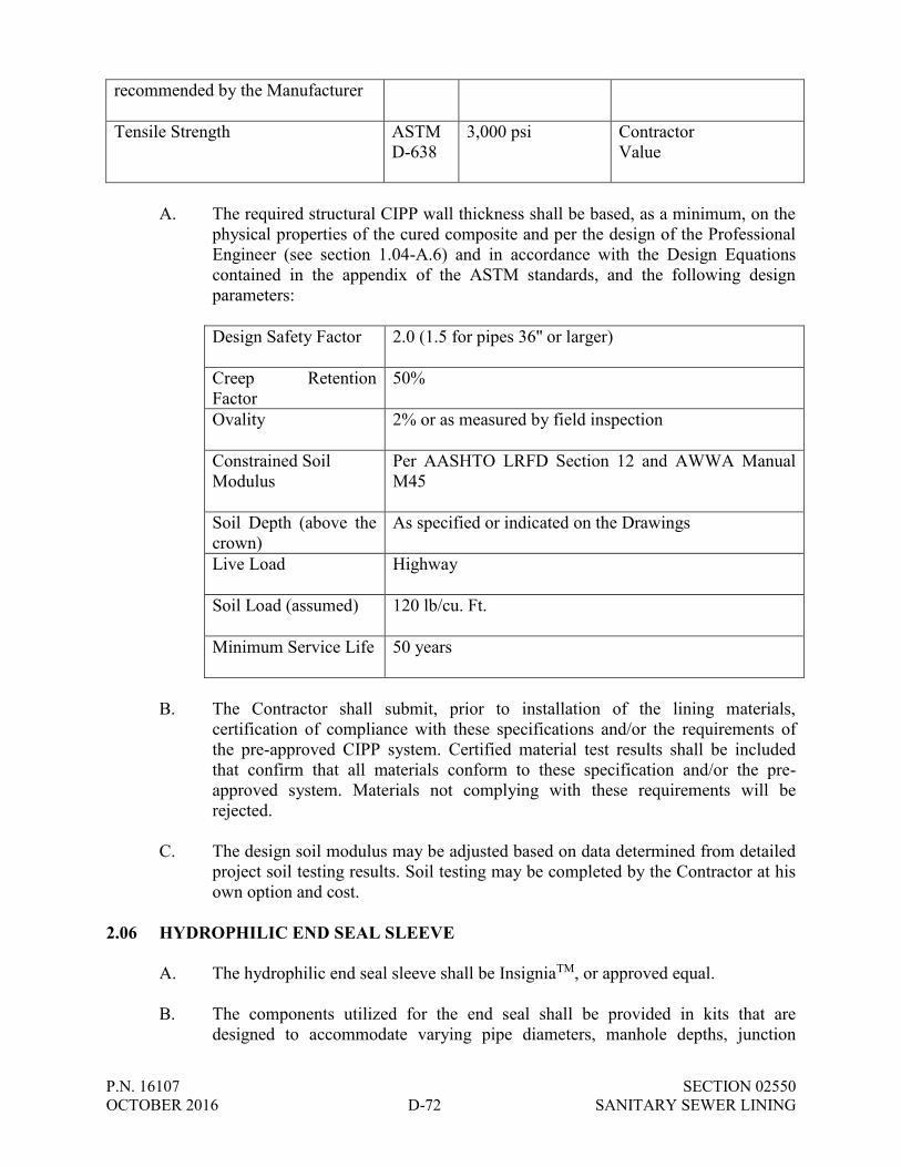
P.N. 16107 SECTION 02550 OCTOBER 2016 D-72 SANITARY SEWER LINING
recommended by the Manufacturer Tensile Strength ASTM
D-638 3,000 psi Contractor
Value
A. The required structural CIPP wall thickness shall be based, as a minimum, on the
physical properties of the cured composite and per the design of the Professional Engineer (see section 1.04-A.6) and in accordance with the Design Equations contained in the appendix of the ASTM standards, and the following design parameters:
Design Safety Factor 2.0 (1.5 for pipes 36'' or larger)
Creep Retention Factor
50%
Ovality 2% or as measured by field inspection
Constrained Soil Modulus
Per AASHTO LRFD Section 12 and AWWA Manual M45
Soil Depth (above the crown)
As specified or indicated on the Drawings
Live Load Highway
Soil Load (assumed) 120 lb/cu. Ft.
Minimum Service Life 50 years
B. The Contractor shall submit, prior to installation of the lining materials,
certification of compliance with these specifications and/or the requirements of the pre-approved CIPP system. Certified material test results shall be included that confirm that all materials conform to these specification and/or the pre-approved system. Materials not complying with these requirements will be rejected.
C. The design soil modulus may be adjusted based on data determined from detailed
project soil testing results. Soil testing may be completed by the Contractor at his own option and cost.
2.06 HYDROPHILIC END SEAL SLEEVE
A. The hydrophilic end seal sleeve shall be InsigniaTM, or approved equal. B. The components utilized for the end seal shall be provided in kits that are
designed to accommodate varying pipe diameters, manhole depths, junction
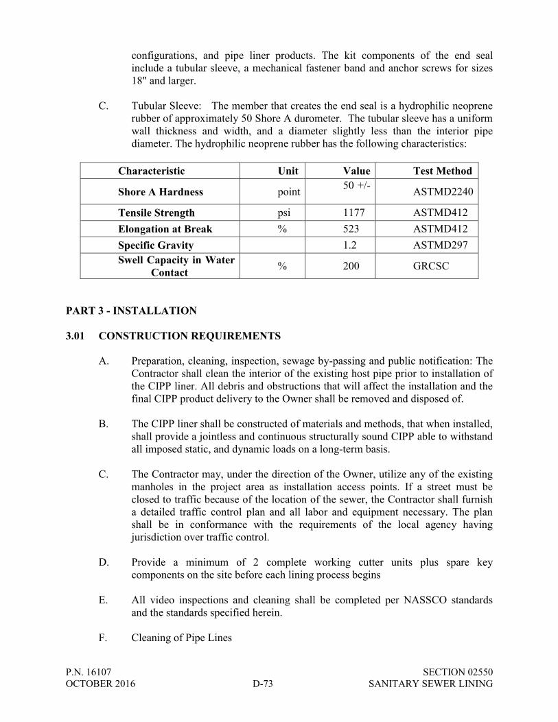
P.N. 16107 SECTION 02550 OCTOBER 2016 D-73 SANITARY SEWER LINING
configurations, and pipe liner products. The kit components of the end seal include a tubular sleeve, a mechanical fastener band and anchor screws for sizes 18" and larger.
C. Tubular Sleeve: The member that creates the end seal is a hydrophilic neoprene
rubber of approximately 50 Shore A durometer. The tubular sleeve has a uniform wall thickness and width, and a diameter slightly less than the interior pipe diameter. The hydrophilic neoprene rubber has the following characteristics:
Characteristic Unit Value Test Method
Shore A Hardness point 50 +/- 5 ASTMD2240
Tensile Strength psi 1177 ASTMD412 Elongation at Break % 523 ASTMD412 Specific Gravity 1.2 ASTMD297 Swell Capacity in Water
Contact % 200 GRCSC
PART 3 - INSTALLATION 3.01 CONSTRUCTION REQUIREMENTS
A. Preparation, cleaning, inspection, sewage by-passing and public notification: The Contractor shall clean the interior of the existing host pipe prior to installation of the CIPP liner. All debris and obstructions that will affect the installation and the final CIPP product delivery to the Owner shall be removed and disposed of.
B. The CIPP liner shall be constructed of materials and methods, that when installed,
shall provide a jointless and continuous structurally sound CIPP able to withstand all imposed static, and dynamic loads on a long-term basis.
C. The Contractor may, under the direction of the Owner, utilize any of the existing
manholes in the project area as installation access points. If a street must be closed to traffic because of the location of the sewer, the Contractor shall furnish a detailed traffic control plan and all labor and equipment necessary. The plan shall be in conformance with the requirements of the local agency having jurisdiction over traffic control.
D. Provide a minimum of 2 complete working cutter units plus spare key
components on the site before each lining process begins E. All video inspections and cleaning shall be completed per NASSCO standards
and the standards specified herein. F. Cleaning of Pipe Lines

P.N. 16107 SECTION 02550 OCTOBER 2016 D-74 SANITARY SEWER LINING
1. Line Obstructions - It shall be the responsibility of the Contractor to clear
the line of obstructions that will interfere with the installation and long-term performance of the CIPP. The sewer shall be cleaned and debris removed to the industry standard of 95% of the pipe diameter to provide for proper installation of product. Moving material from manhole section to manhole section shall not be allowed. Obstructions include, but are not limited to, protruding taps, mineral deposits, roots, and other debris. If pre-installation inspection reveals an obstruction, misalignment, broken or collapsed section or sag that was not identified as part of the original scope of work and will prohibit proper installation of the CIPP, the Contractor may be directed by the Engineer and Owner to correct the problem(s) prior to lining by utilizing open cut repair methods. Do not proceed with repair in areas of discrepancy unless directed to do so.
2. As applicable the contractor shall either plug or install a flow bypass
pumping system to properly clean the pipe lines. Precaution shall be taken, by the Contractor in the use of cleaning equipment to avoid damage to the existing pipe. The repair of any damage caused by the cleaning equipment shall be the responsibility of the Contractor.
3. Solid debris and deposits shall be removed from the system and disposed
of properly by the Contractor at an offsite location at his own option and cost at an offsite location.
4. Contractor shall perform post-cleaning video inspections of the pipelines.
Only PACP certified personnel trained in locating breaks, obstacles and service connections by closed circuit television shall perform the inspection. The Contractor shall provide the Owner a copy of the pre-cleaning and post-cleaning video and suitable log, and/or in digital format for review prior to installation of the CIPP and for later reference by the Owner.
G. By-passing Existing Sewage Flows – Refer to Section 02760. H. The Contractor shall be responsible for confirming the locations of all branch
service connections prior to installing and curing the CIPP. In the event the status of a service connection cannot be adequately defined, the Engineer and Owner will make the final decision, prior to installation and curing of the liner, as to the status. Typically only service connections deemed “active” shall be reopened by the Contractor.
3.02 WATER FOR CONSTRUCTION
A. The Contractor will be permitted to use the Utility water supply where available for incidental uses providing a permit is first obtained from the Oak Creek Water and Sewer Utility, 170 West Drexel Avenue, Oak Creek, Wisconsin. There will be no charge for this water use unless the amount is determined to be excessive as

P.N. 16107 SECTION 02550 OCTOBER 2016 D-75 SANITARY SEWER LINING
defined by the Utility Engineer. If an invoice is issued and said bill is not paid by completion of the project, the amount of said bill will be deducted from the final contract payment. Any attempt to obtain water without the Utility’s approval will result in fines and penalties.
B. The Contractor shall contact the Utility at least 3 days prior to the expected need
for municipal water at (414) 570-8200, Ext. 38. C. All costs for water use will be considered incidental to other bid items.
3.03 INSTALLATION AND CURING OF LINER
A. The CIPP Liner shall be installed and cured in the host pipe per the manufacturer’s specifications as described and submitted in the PWS.
B. Installation of the liner shall not begin until the Contractor has installed the
required plugs or a sewage by-pass system as specified in Section 02760. C. CIPP installation shall be in accordance with the applicable ASTM standards with
the following modification:
1. The wet-out tube shall be positioned in the pipeline using the method specified by the manufacturer. Care should be exercised not to damage the tube as a result of installation. The tube should be pulled-in or inverted through an existing manhole or approved access point and fully extend to the next designated manhole or termination point.
D. Prior to installation and as recommended by the manufacturer remote temperature
gauges or sensors shall be placed inside the host pipe to monitor the temperatures during the cure cycle. Liner and/or host pipe interface temperature shall be monitored and logged during curing of the liner.
E. To monitor the temperature of the liner wall and to verify correct curing and
where specified by the contract documents, temperature sensors shall be placed between the host pipe and the liner in the bottom of the host pipe (invert) throughout its length to monitor the temperature on the outside of the liner during the curing process. The temperature sensors shall be placed at intervals as recommended by the sensor manufacturer. Additional sensors shall be placed where significant heat sinks are likely or anticipated. The sensors, if installed, shall be monitored by a computer using a tamper proof data base that is capable of recording temperatures at the interface of the liner and the host pipe.
F. Provide water stops in manholes as required to prevent infiltration into the
system. G. Curing shall be accomplished by utilizing the appropriate medium in accordance
with the manufacturer’s recommended cure schedule. The curing source, or in and output temperatures, shall be monitored and logged during the cure cycles if
P.N. 16107 SECTION 02550 OCTOBER 2016 D-76 SANITARY SEWER LINING
applicable. The manufacturer’s recommended cure method and schedule shall be used for each line segment installed, and the liner wall thickness and the existing ground conditions with regard to temperature, moisture level, and thermal conductivity of soil, per ASTM as applicable, shall be taken into account by the Contractor.
H. For heat cured liners, if any temperature sensor or multiple sensors do not reach
the temperature as specified by the manufacturer to achieve proper curing or cooling, the installer shall make necessary adjustments to comply with the manufacturer’s recommendations. The system computer should have an output report that specifically identifies each installed sensor station in the length of pipe, indicates the maximum temperature achieved and the sustained temperature time. Each sensor should record both the maximum temperature and the minimum cool down temperature and comply with the manufacturers recommendations. The cure procedure shall be in accordance with the manufacturer’s recommendation as included in the PWS submission by the contractor.
3.04 COOL DOWN
A. The Contractor shall cool the CIPP in accordance with the approved CIPP manufacturer’s recommendations as described and outlined in the PWS.
B. Temperatures and curing data shall be monitored and recorded by the Contractor
throughout the installation process to ensure that each phase of the process is achieved as approved in accordance with the CIPP System manufacturer’s recommendations.
3.05 FINISH
A. The installed CIPP shall be continuous over the entire length of a sewer line section and be free from visual defects such as foreign inclusions, dry spots, pinholes, major wrinkles and de-lamination. The CIPP shall be impervious and free of any leakage from the pipe to the surrounding ground or from the ground to inside the lined pipe.
B. Any defect, which will or could affect the structural integrity or strength of the linings, shall be repaired at the Contractor’s expense in accordance with the procedures submitted under Section 1.08 CIPP Repair/Replacement.
C. The beginning and end of the CIPP shall be sealed to the existing host pipe. The
sealing material shall be compatible with the pipe end and shall provide a watertight seal.
D. If any of the service connections leak water between the host pipe and the
installed liner, the connection mainline interface shall be sealed to provide a water tight connection.
E. If the wall of the CIPP leaks, it shall be repaired or removed and replaced with a
watertight pipe as recommended by the manufacture of the CIPP system.

P.N. 16107 SECTION 02550 OCTOBER 2016 D-77 SANITARY SEWER LINING
F. Liner shall conform to shape of pipe existing before installation and not be out of
round by more than 15%.
3.06 MANHOLE CONNECTIONS, RECONNECTIONS OF EXISTING LATERALS, AND SECTIONAL LINERS
A. The InsigniaTM hydrophilic end seal compatible with the installed CIPP shall be
applied at manhole/wall interface, existing lateral reconnections, and at the ends of all sectional liners in accordance with the CIPP System and hydrophilic end seal manufacturer’s recommendations. Reconstruct benches and channels in manholes with hydraulic cement or equal to match new invert elevations.
B. Immediately after the sewer lining is complete and any in situ testing is complete,
the Contractor shall re-establish the required service connections before any adverse effect is experienced by residents. This shall generally be done from the interior of the pipe by means of a television camera and a remotely controlled cutting device.
C. Reconnections of existing services shall be made after the CIPP has been
installed, fully cured, and cooled down. It is the CONTRACTOR’S responsibility to make sure that all active service connections are reconnected. Inactive laterals that are not in service shall not be reconnected unless they provide future service to a vacant lot. Service connection locations shall be determined from CCTV inspection completed prior to lining.
D. External reconnections are to be made with a tee fitting in accordance with CIPP
System manufacturer’s recommendations. Saddle connections shall be seated and sealed to the new CIPP using grout or resin compatible with the CIPP.
E. A CCTV camera and remote cutting tool shall be used for internal reconnections.
The machined opening shall be at least 90 percent of the service connection opening and the bottom of both openings must match. The opening shall not be more than 100 percent of the service connection opening. The edges of the opening shall not have pipe fragments or liner fragments, which may obstruct flow or snag debris. In all cases the invert of the sewer connection shall be cut flush with the invert entering the mainline.
F. In the event that service reinstatements result in openings that are greater than 100
percent of the service connection opening, the Contractor shall install a CIPP type repair, sufficiently in size to completely cover the over-cut service connection. No additional compensation will be paid for the repair of over-cut service connections.
G. Coupons of pipe material resulting from service tap cutting shall be collected at
the next manhole downstream of the pipe rehabilitation operation prior to leaving the site. Coupons may not be allowed to pass through the system.

P.N. 16107 SECTION 02550 OCTOBER 2016 D-78 SANITARY SEWER LINING
H. Sewer service lines to individual users may be disconnected for a period of time not to exceed more than 8 hours. The Contractor will be responsible for providing temporary service to facilities that are out of service for more than 8 hours. The Contractor shall be ready and immediately available for any property owner backup issues that arise from the work being done and/or disconnected service. For example, the Contractor may need to provide emergency contact information to the property owner so that the owner knows who to contact in the event of an emergency/backup situation.
I. If excavation is necessary to re-establish connections, the cost and liability shall
be the responsibility of the Contractor, including any additional landscaping or turf establishment.
J. Maintain a record of each service re-connection as follows:
a. Type of service re-connection.
b. Distance from downstream manhole. c. Furnish to Engineer weekly at a minimum.
K. Lateral Connection Testing:
1. Proof via air test or other approved method each reinstated service lateral
connection (if Owner elects to accept alternate method).
2. Active leaks at reinstated service lateral connections and reinstated service connections which do not pass a proof test shall be sealed by chemical grout or other method approved by the Engineer (if Owner elects to accept alternate method).
3.07 TESTING OF INSTALLED CIPP
A. The physical properties of the installed CIPP shall be verified through field sampling and laboratory testing. All materials for testing shall be furnished by the Contractor to the Owner for testing. All materials testing shall be performed at the Owner’s expense, by an independent third party laboratory selected by the Owner as recommended by the CIPP manufacturer. All tests shall be in accordance with applicable ASTM test methods to confirm compliance with the requirements specified in these contract documents.
B. The Contractor shall provide samples for testing to the Owner from the actual
installed CIPP liner. Samples shall be provided, at a minimum from one location per 1000 linear feet of CIPP installed or as required by the Owner. The sample shall be cut from a section of cured CIPP that has been inverted or pulled through a like diameter pipe which has been held in place by a suitable heat sink, such as sandbags. All curing, cutting and identification of samples will be witnessed by the Engineer and Owner and transmitted by the Owner to the testing laboratory.
P.N. 16107 SECTION 02550 OCTOBER 2016 D-79 SANITARY SEWER LINING
The Opening produced from the sample shall be repaired in accordance with manufacturers recommended procedures.
C. The laboratory results shall identify the test sample location as referenced to the
nearest manhole and station. Final payment for the project shall be withheld pending receipt and approval of the test results. If properties tested do not meet the minimum physical and thickness requirements, the CIPP shall be repaired or replaced by the Contractor unless the actual physical properties and the thickness of the sample tested meet the design requirements as required in the contract.
D. Chemical resistance - The CIPP system installed shall meet the chemical
resistance requirements of ASTM D5813. CIPP samples tested shall be of fabric tube and the specific resin proposed for actual construction. It is required that CIPP samples without plastic coating meet these chemical testing requirements. A certification may be submitted by the contractor, from the manufacturer, verifying that the chemical resistance of the CIPP meets the contract requirements.
E. Hydraulic Capacity - Overall, the hydraulic capacity shall be maintained as large
as possible. The installed CIPP shall at a minimum be equal to the full flow capacity of the original pipe before rehabilitation. Calculated capacities may be derived using a commonly accepted roughness coefficient for the existing pipe material taking into consideration its age and condition.
F. The installed CIPP thickness shall be measured for each line section installed. If
the CIPP thickness does not meet that specified in the contract and submitted as the approved design by the Contractor then the liner shall be repaired or removed unless the tested physical properties and the thickness of the sample tested meet the design requirements as required in the contract. The liner thickness shall have tolerance of minus 5% plus 10%.
3.08 FINAL ACCEPTANCE
A. All CIPP sample testing and repairs to the installed CIPP as applicable, shall be completed, before final acceptance, meeting the requirements of these specifications and documented in written form.
B. The Contractor shall perform a detailed closed-circuit television inspection in
accordance with ASTM standards, in the presence of the Engineer and Owner after installation of the CIPP liner and reconnection of the side sewers. A radial view (pan and tilt) TV camera shall be used. The finished liner shall be continuous over the entire length of the installation and shall be free of significant visual defects, damage, deflection, holes, leaks and other defects. Unedited digital documentation of the inspection shall be provided to the Owner within ten (10) working days of the liner installation. The data shall note the inspection date, location of all reconnected side sewers, debris, as well as any other defects in the liner, including, but not limited to, gouges, cracks, bumps, or bulges. If post installation inspection documentation is not submitted within Ten (10) working days of the liner installation, the Owner may at its discretion suspend any further
P.N. 16107 SECTION 02550 OCTOBER 2016 D-80 SANITARY SEWER LINING
installation of CIPP until the post-installation documentation is submitted. As a result of this suspension, no additional work completion time will be added to the contract, nor will any adjustment be made for increase in cost. Immediately prior to conducting the closed circuit television inspection, the Contractor shall thoroughly clean the newly installed liner removing all debris and build-up that may have accumulated.
C. After installation and prior to televising, the Contractor shall bypass pump from
the upstream manhole and plug both ends of the pipe to ensure a clean line during the CCTV inspection. The intent is to be able to clearly see the bottom of the pipe. In the case of sags in the line, the pipe shall be cleared of any standing water to provide continuous visibility during the inspection.
D. Where leakage is observed through the wall of the pipe, the contractor shall
institute additional testing including but not limited to air testing, localized testing and any other testing that will verify that the leakage rate of the installed CIPP does not exceed acceptable tolerances specified in the contract.
3.09 POST-INSTALLATION CLEANING AND RESTORATION
A. At completion of daily operations, remove rubbish, debris, dirt, equipment, and excess material from site. Clean and restore adjacent surfaces soiled by and during course of work.
B. After sewer rehabilitation is complete, leave all sanitary sewers in completely
cleaned condition. Remove all mortar, construction debris and asphalt from all lid slots, between the manhole lid and frame, as well as on the manhole walls and bench to the sewer flow line. Clean all flow lines, allowing flow without obstructions.
a. If the Public Works Department has to remove any debris that is left in
structures and/or sewer lines after the sewer rehabilitation has been completed, time and equipment costs will be billed to the Contractor.
3.10 SEWAGE SPILL PROCEDURES
A. Immediately notify the Engineer and Owner. B. Take immediate action to prevent sewage from entering any water body or storm
sewer by directing sewage flow into the existing sanitary sewer system. 3.11 CCTV INSPECTION OF SEWER PIPELINES
A. General
1. Televise sanitary sewer after pipe lining work and provide two copies of a portable hard drive and report to Engineer and Owner.

P.N. 16107 SECTION 02550 OCTOBER 2016 D-81 SANITARY SEWER LINING
2. Notify the Engineer and Owner at least three (3) days prior to completing televising. Do not complete televising unless an Owner’s representative is present or if this requirement is waived by the Owner or Engineer.
3. Clean the sewer prior to televising.
4. All defects shall be corrected and any dirt, gravel, or foreign material removed from the sewer prior to acceptance by the Owner.
5. Re-televise all lines that were either repaired or cleaned. If debris is still found, it shall be removed and the sewer re-televised until it is clean.
B. CCTV Examination
1. Use pan and tilt color 3-lux camera to view the sewer service lateral connections.
2. The camera used for the inspection shall be one specifically designed and constructed for such inspection. The camera shall be capable of radial view for inspection of the top, bottom, and sides of the pipe and for looking up leteral connections. The camera shall be mounted on adjustable skids or self-propelled. High intensity lighting for the camera shall be supplied by a lamp on the camera. The lighting system shall be capable of lighting the entire periphery of the pipe at a distance of 5 feet. The camera shall be capable of operating in 100% humidity conditions and shall have a minimum of 650 lines of resolution.
3. The camera shall be moved through the main in either direction at a uniform rate, stopping when necessary to insure proper documentation of the sewer condition but in no case will the camera be pulled at a speed greater than 30 fpm. At all defects and service connections, the camera shall be stopped and the pan and tilt features used to obtain a clear picture.
4. If the camera will not pass through the entire sewer section, the Contractor shall re-setup his equipment in a manner so that the inspection can occur from the other manhole. If the camera fails to pass through the entire sewer section from the opposite end, the Engineer will determine if a blocikage previously occurred based on the most recent televising completed. If a blockage did not previously occur, the Contractor shall be responsible for removing such blockage and re-televising the line.
5. The camera shall be kept clean at all times during the televising process. Remove the camera as necessary to obtain clear video.
END OF SECTION

P.N. 16107 SECTION 02760 OCTOBER 2016 D-82 BYPASS PUMPING
SECTION 02760
BYPASS PUMPING
PART 1 – GENERAL
A. This Section includes the minimum requirements necessary for bypass pumping and/or diversion of existing sewage flows during the sanitary sewer lining and relaying process.
PART 2 – PRODUCTS
None. PART 3 – EXECUTION
A. The Contractor shall be responsible for maintaining sewage flow during sewer
lining, and relay. Sewage flow may be maintained by bypass pumping from upstream manholes or by other suitable means provided by the Contractor. The Contractor shall be responsible for damage to property resulting from sewer backups caused by his sewage bypass operations.
B. All bypassed sewage shall be discharged into downstream sanitary sewers.
Sewage shall not be bypassed into storm sewers, ditches, or waterways. C. The Contractor shall provide for the flow of existing mainline and service
connection effluent around the section or sections of pipe designated for lining and relay.
D. With most small diameter pipelines, particularly on terminal sewers, plugging will
be adequate but must be monitored on a regular basis to prevent backup of sewage into adjacent homes. Service connection effluent may be plugged only after proper notification to the affected residence and may not remain plugged overnight.
E. Installation of the liner and relay segments shall not begin until the Contractor has
installed the required plugs or a sewage by-pass system and all pumping facilities have been installed and tested under full operating conditions including the bypass of mainline and side sewer flows.
F. Once the lining process has begun, existing sewage flows shall be maintained,
until the resin/felt tube composite is fully cured, cooled down, televised, and the CIPP ends finished. Once the pipe relay has begun, existing flows shall be maintained until the new pipe is fully installed and tested.

P.N. 16107 SECTION 02760 OCTOBER 2016 D-83 BYPASS PUMPING
G. The Contractor shall coordinate sewer bypass and flow interruptions at least 14 days in advance with the Owner and at least 48 hours day in advance with the property owners and businesses.
H. The pump and bypass lines shall be of adequate capacity and size to handle peak
flows at each proposed location. The existing level of service of the OAK CREEK WATER AND SEWER UTILITY sanitary sewer system should not be adversely affected throughout the project. If the Contractor feels that bypass pumping will affect the level of service in the OAK CREEK WATER AND SEWER UTILITY system, the Contractor must notify the Owner and Engineer before proceeding with the work.
I. The Contractor shall submit a detail of the bypass plan and design to the Owner
and Engineer before proceeding with any CIPP installation or pipe relay. The bypass plan shall identify the bypass pumping locations that will be used to complete the sanitary sewer lining and relay work in the project. The bypass plans will need to be approved by the Owner and Engineer prior to work and shall include:
1. Location of upstream and downstream manholes where sanitary sewer
flow will be diverted around pipes to be lined and relayed. 2. Length of time that the bypass equipment is planned to be in service. 3. Size and type of pump and piping equipment used in each bypass
application to maintain existing level of service in the sewer system. 4. Steps the Contractor will take to prevent flooding in the event that the
bypass facilities fail or their capacity is exceeded.
J. Under no circumstances shall the Contractor permit bypasses sewage onto or into the ground.
END OF SECTION

P.N. 16107 SECTION 02770 OCTOBER 2016 D-84 TEST AND SEAL LATERAL CONNECTIONS
SECTION 02770
TEST AND SEAL LATERAL CONNECTIONS PART I – GENERAL
1.01 DESCRIPTION
A. Provide all labor, materials, tools, equipment and incidentals required for testing
active lateral connections located in the lengths of sewer lining segments designated on the Drawings by applying a positive air pressure to the connection, monitoring and recording the pressure in the void. The intent of connection testing is to identify those lateral connections that are not watertight and that can be successfully sealed by packer injection grouting. It the Utility’s intent to only test at the connection and not at any other joints inside of the lateral.
B. Provide all labor, materials, tools, equipment, and incidentals required to grout
lateral connections to the mains using the packer injection method. C. Packer injection grouting is used to seal annular space between liners and host
pipes at lateral connections. Packer injection grouting shall be accomplished by pressure injection of chemical grout into the soils encompassing the exterior of lateral connection. Chemical grouts shall be designed to be injected into the soil surrounding the pipe, which stabilizes the soil and forms a permanent impermeable seal called a grout/soil ring, and into the annular space between liners and host pipes. Adequate volumes of grout must be injected to form an effective seal. Adequate amounts of grout are based generally upon pipe size and field conditions. This application will be through lateral connections through penetrations from within the pipe by using the packer method in tandem with a closed circuit television (CCTV) inspection system.
1.02 REQUIREMENTS
A. Contract requires work in active sewers. CONTRACTOR shall follow all federal, state and local requirements for safety in confined spaces and uniform traffic controls.
B. Additional safety considerations including safely handling, mixing, and
transporting of chemical grouts should be provided by the grout manufacturer/supplier, and should include safe operating practices and procedures, appropriate personal protective equipment (PPE) for the various grouting operations, and proper storage, transportation, mixing, and disposal of grouts, additives, and their associated containers.
C. Require completion of grout handling and mixing training certification from the
grout manufacturer/supplier for personnel working with chemical grouts and additives.

P.N. 16107 SECTION 02770 OCTOBER 2016 D-85 TEST AND SEAL LATERAL CONNECTIONS
1.03 SUBMITTALS
A. The CONTRACTOR shall provide a minimum 48-hour advance written notice of proposed testing schedules and testing procedures for review and concurrence of the ENGINEER.
B. Equipment operating procedures and systems. C. Chemical grout information:
1. Description of chemical grout materials to be used per section 2.03. 2. Description of proposed additives to be used per section 2.04. 3. Manufacturers recommended procedures for storing, mixing, testing and
handling of chemical grouts. 4. MSDS sheets for all materials to be used.
D. Identify the manufacturer(s) and model(s) of the packers to be utilized on the
project. E. Upon completion of each pipe segment, submit to ENGINEER a report showing
the following data for each lateral connection tested, grouted or attempted to be grouted.
1. Identification of each lateral connection tested by assigned manhole-to-
manhole ID, including location stationing of each connection tested and location of any connections not tested with an explanation for not testing.
2. Type of pipe material and diameter. 3. Test pressure used and duration of test. 4. Pass/fail results for each connection tested. 5. Volume of grout material used on each connection. 6. Gel set time used (cup test results from tanks) 7. Grout mix record of the batches mixed including amount of grout and
catalyst, additives, temperature of the grout solution in tanks. 8. Name of operator conducting testing and sealing shall be noted on the
reports.
P.N. 16107 SECTION 02770 OCTOBER 2016 D-86 TEST AND SEAL LATERAL CONNECTIONS
9. Video recordings
a. Video recording shall include testing and sealing operations for each lateral (including inflation and deflation over the lateral) displaying the final air test of laterals.
b. Additional final recording, if specified, shall include inspection of
the lateral after all grouting work is complete. 1.04 REFERENCE STANDARDS TO BE USED
A. National Association of Sewer Service Companies (NASSCO) prepared Pipeline Assessment and Certification Program (PACP), TV inspection form and sewer condition codes
B. ASTM F2304 Standard Practice for Rehabilitation of Sewers using Chemical
Grouting (latest revision) C. ASTM F2454 Standard Practice for Sealing Lateral Connections and lines from
the Mainline Sewer Systems by Lateral Packer Method, Using Chemical Grouting (latest revision)
PART II – PRODUCTS 2.01 TESTING EQUIPMENT AND GROUTING EQUIPMENT
A. The basic equipment used for laterals connected to the mainline shall consist of a remotely operated color television camera capable of pan and tilt, lateral connection testing device (referred to hereafter as a packer), and test monitoring equipment. The equipment shall be constructed in such a way as to provide means for introducing air under pressure into the void area created by the expanded ends of the packer against the host pipe and a means for continuously measuring, viewing and recording the actual static pressure of the test medium and grout within the void area only. The packer shall be of a size less than the diameter of the host pipe, with the cables at either end used to pull it through the line and may be constructed in such a manner as to allow a restricted amount of sewage to flow at all times. Packer shall be expanded by air pressure. Packers shall be of low void space construction with void volume given by the packer manufacturer.
B. The device for testing lateral connections shall consist of inflatable mainline end
elements and a lateral grouting plug that creates a void area extending beyond the main connection. Whenever possible, use a lateral grouting plug sized to match the diameter of the lateral being grouted. Where the lateral is capped, utilize alternate lateral grouting plug or equipment sized appropriately for the capped lateral. In cases were the lateral transitions from 6” to 4” in diameter, use a 4”
P.N. 16107 SECTION 02770 OCTOBER 2016 D-87 TEST AND SEAL LATERAL CONNECTIONS
lateral grouting plug. However, it is possible that due to physical restrictions the lateral plug may not launch and thus the service may not be able to be grouted.
C. Void pressure data shall be transmitted from the void area to the monitoring
equipment or video picture of a pressure gauge mounted on the packer and connected to the void area. All test monitoring shall be above ground and in a location to allow for simultaneous and continuous observation of the televising monitor and test monitoring equipment.
D. Grouting equipment shall consist of the packer, appropriate pumping and hosing
systems capable of supplying an uninterrupted flow of sealing materials to completely fill the voids. Grout pumping system shall be sized to deliver a mixed volume of grout at a minimum of 3 gpm and 30 gallons of uninterrupted flow within 10 minutes.
E. Volume of mixed grout pumped must be capable of being measured and recorded
for each grouted connection. Generally, the equipment shall be capable of performing the specified operations in sewers where flows do not exceed 25 percent of pipe diameter unless permitted by ENGINEER.
F. Connection and lateral service sealing shall be accomplished using the lateral
grouting plugs and push packers specified above. Provide back-up bladders for each packer on-site at all times during grouting procedures.
G. Equipment for cleaning lateral blockages shall be readily available while any
lateral grouting work is being performed. 2.02 GROUTS - GENERAL
A. All grout materials must have the following characteristics:
1. While being injected, the grout must be able to react /perform in the presence of water (groundwater).
2. The ability to increase grout mix viscosity, density and gel strength by increased concentration of constituents or the use of approved additives.
3. The cured grout must withstand submergence in water without
degradation. 4. The resultant grout formation must be homogeneous and prevent the
passage of water (infiltration) through the lateral connection. 5. The grout must not be biodegradable. 6. The cured grout should be chemically stable and resistant to organics
found in sewage.

P.N. 16107 SECTION 02770 OCTOBER 2016 D-88 TEST AND SEAL LATERAL CONNECTIONS
7. Residual grout shall be easily removable from the sewer line to prevent blockage of the sewage flow.
B. Handle, mix, and store grout in accordance with the manufacturer’s
recommendations. The materials shall be delivered to the site in unopened original manufacturer’s containers.
2.03 CHEMICAL GROUTS
A. Water based chemical grouts shall have the following characteristics:
1. A minimum of 10% acrylamide base material by weight in the total grout mix. A higher concentration of acrylamide base material is recommended to increase strength or offset dilution during injection.
2. The ability to tolerate some dilution and react in moving water during
injection. 3. A viscosity of approximately 2 centipoise, which can be increased with
approved additives. 4. A controllable reaction time from 10 seconds to 1 hour. 5. A reaction (curing) that produces a homogenous, chemically stable,
nonbiodegradable, firm, flexible gel. 6. The ability to increase mix viscosity, density and gel strength by increased
concentrations of the mix constituents or by the use of approved additives. 7. Product Manufacturer:
a. Avanti AV-100, Avanti AV-118; or equal.
B. Acrylate base grout shall have the following characteristics:
1. A minimum of 10% acrylate base material by weight in the total grout mix.
2. The ability to tolerate some dilution and react in moving water during
injection. 3. A viscosity of approximately 1-3 centipoise, which can be increased with
approved additives. 4. A controllable reaction time from 10 seconds to 1 hour. 5. A reaction (curing) that produces a homogenous, chemically stable,
nonbiodegradable, firm, flexible gel.

P.N. 16107 SECTION 02770 OCTOBER 2016 D-89 TEST AND SEAL LATERAL CONNECTIONS
6. The ability to increase mix viscosity, density and gel strength by the use of
approved additives. 7. Product Manufacturer:
a. DeNeef AC-400, DeNeef Gelacryl SR, Avanti AV-160; or equal. 2.04 ADDITIVES
A. At the CONTRACTOR'S discretion and according to field conditions, additives may be selected and used within the manufacturers recommended quantities.
B. Strengthening Agents
1. For lateral connections, a latex or “diatomaceous earth” additive may be added to increase compressive and tensile strength. The quantity of strengthening agent additive shall be as recommended by the manufacturer and approved by ENGINEER. Product Manufacturer:
a. Avanti AV-257 Icoset, DeNeef Reinforcing Agent; or equal.
C. Root Inhibitor
1. When roots are present, for lateral connection grouting, a root deterrent chemical shall be added to control root re-growth. The quantity of inhibitor shall be as recommended by the manufacturer and approved by ENGINEER.
2. Product Manufacturer:
a. Avanti AC-50W; or equal. D. Dye - A manufacturer approved water soluble dye without trace metals may be
added to the grout tank(s) for visual confirmation. E. Gel Time Modifier - A gel time extending agent may be used in accordance with
the manufacturer’s recommendations to extend gel time as necessary. F. Freeze/Thaw - In those lines where the grouting material may be exposed to a
freeze-thaw cycle, ethylene glycol or other ENGINEER approved additive shall be used to prevent chemical grout cracking once set.
G. When using non soluble additives the grout tanks must have mechanical mixing
devices to keep the additives in suspension and maintain a uniform solution of grout and additive.
P.N. 16107 SECTION 02770 OCTOBER 2016 D-90 TEST AND SEAL LATERAL CONNECTIONS
PART 3 – EXECUTION 3.01 FLOW CONTROL
A. To effectively conduct sealing operations, it may be necessary to provide for flow control or pumping of sewage flows. The Contractor shall be responsible for providing the means and equipment for such flow control or pumping. The Contractor shall be responsible for damages to property due to sewer backup while controlling sewage flow. All costs for flow control, temporary pumping, etc., shall be considered incidental and included in the unit prices bid for other items.
B. When sewer line flows are above the minimum requirements (generally not more
than 1/4 of the pipe diameter) or inspection of the complete periphery of the pipe is necessary to effectively conduct the sealing operations, one or more of the following methods of flow control shall be used at no extra cost to the Owner.
1. Plugging or Blocking. A sewer line plug shall be inserted into the line at a
manhole upstream from the section to be tested and/or sealed. The plug shall be so designed that all or any portion of the sewage flows can be released. Flows shall be restored to normal or not more than 1/3 of the pipe diameter during the joint testing and joint sealing operation.
2. Pumping and Bypassing. Where pumping is required, in the opinion of the
Engineer, to assure completion of the sealing work, the Contractor will be required to furnish pumping equipment, conduits, etc. in accordance with Section 02760. Under no circumstances will bypassing of untreated wastewater to any storm drainage facility or surface watercourse be allowed.
3.02 CONTROL TESTS
A. Packer Tests - Demonstrate the acceptable performance of air test.
1. To insure the accuracy, integrity and performance capabilities of the testing equipment, a demonstration test will be performed in an above-ground 8” nominal diameter test cylinder suitable to contain the full length of the packer and sustain the void test pressure. The test cylinder shall be equipped with a void release valve to exercise a controlled release of pressurized air from the void area to test the packer under both sound and leaking conditions. The test cylinder shall also be equipped with a local pressure gauge (0-25 psi) within the void space.
a. With the void release valve sealed, inflate the packer and air test
void at 7-10 psi. The observed void pressure at the test cylinder pressure gauge must be within ±1.0 psi of the reading in the
P.N. 16107 SECTION 02770 OCTOBER 2016 D-91 TEST AND SEAL LATERAL CONNECTIONS
control center/studio void pressure gauge and follow both up and down pressure changes (allowing time for pressure equalization).
b. If above test is passed, crack the release valve to simulate a very
small leak.
The cylinder shall be equipped with a void release valve to exercise a controlled release of the test media with the associated pressure drop to be equally displayed ±1.0 psi of the cylinder gauge and test monitoring equipment.
2. After entering each pipeline segment with the test equipment, but prior to
the commencement of lateral connection testing, position the packer on a section of sound sewer pipe between pipe joints, and perform a test as specified. The equipment shall hold a 7-10 psi test pressure for a period of 15 seconds with a pressure drop of less than 1 psi. In the event of a failed test, repair any defective equipment and re-test to verify proper operation of all equipment at no additional compensation. Should it be found that the surface or porosity conditions of the barrel of the sewer pipe cannot meet the joint test requirements, then the performance testing shall be waived or modified as determined by the ENGINEER.
3. If air testing cannot be performed successfully, repair or otherwise modify
air test equipment and repeat the tests. This test may be required at any other time during the performance of joint testing work if the ENGINEER suspects the testing equipment is not functioning properly.
B. Pump Tests - At the beginning of the contract, prior to application of grout,
perform a pump test to determine if proper ratios are being pumped from the grout component tanks at the proper rates and to measure pump rates. Use separate containers to capture the discharges from each of the grout component hoses, to simulate the actual volumes of each component through the interconnect hoses, hose reel and length of grout hose and confirm accuracy of grout pump totalizer. Take corrective action if ratios or rates are not within manufacturer’s recommended standards.
C. Grout Tests - Perform and record a grout gel test in the presence of the
ENGINEER by recording the grout tank solution temperature, catalyst tank solution temperature, ambient air temperature in truck, and gel time of the sample whenever the following conditions occur:
1. At the beginning of each day; the material in the hoses shall be recycled to
the tanks and a sample shall be taken. 2. When new batches of grout are mixed. 3. Whenever the temperature in the tanks or ambient temperature have
changed by more than +/- 10°F from the previous gel test.

P.N. 16107 SECTION 02770 OCTOBER 2016 D-92 TEST AND SEAL LATERAL CONNECTIONS
3.03 PIPE PREPARATION
A. Prior to the application of the chemical grouting materials, the CONTRACTOR shall thoroughly clean the sewer designated to receive the chemical grouting. Cleaning shall constitute removal of all mineral deposits, protruding taps, loose debris, and solids which inhibit proper seating of the packer.
3.04 ROOTS AND LOOSE DEBRIS IN LATERAL CONNECTIONS
A. Remove all roots and loose debris from laterals connected to manholes for the length of lateral to be tested/grouted.
B. During mainline sewer cleaning or lateral connection testing, document all lateral
connections containing roots, mineral deposits or obstructive conditions that are either (a) greater than fine roots or (b) of a nature to prevent testing and sealing of connection. For each such connection, submit a screen shot image clearly showing the extent of roots or obstructive condition to the ENGINEER. Submit images in electronic format, labeled and organized in a manner to easily retrieve the image for the lateral connection in question. The list of lateral connections with roots shall include upstream and downstream manhole numbers and stationing. ENGINEER will review the list of lateral connections containing roots and obstructions and direct CONTRACTOR as to which laterals are to be (a) cleaned and grouted, (b) grouted without cleaning – in which case such lateral connection would be excluded from warranty testing, or (c) removed from the scope of work.
3.05 GROUT PREPARATION
A. Follow the manufacturer’s recommendations for the mixing and safety procedures.
B. Adjust gel time as necessary to compensate for changes in temperature in grout
component tanks or hoses. The addition of dilution water to extend gel times is not acceptable unless resulting base grout tank only material exceeds 20% by weight for solution grouts.
C. During the grouting process, the Grouting Technician shall monitor the grout
component tanks to make sure that proper ratios are being pumped. If unequal levels are noted in the tanks, repeat the pump test as described above and correct any defective equipment.
D. Gel times shall be calculated using the following formula unless CONTRACTOR
experience and/or field conditions dictate otherwise. Any alterations of the gel time formula shall be approved by the ENGINEER.

P.N. 16107 SECTION 02770 OCTOBER 2016 D-93 TEST AND SEAL LATERAL CONNECTIONS
E. Packer/Pipe void shall be defined as the volume between the inflated packer and the inside pipe wall when the packer is inflated per manufacturer recommendations. For example: an 8” pipe with a packer void space of 0.3 gallons and a 3 gpm pumping rate would provide
3.06 TESTING AND GROUTING DEFECTS
A. Any structurally undamaged lateral connection that structurally fails (breaks) during testing and grouting that are documented on video to have been done under normal pressure conditions shall be the OWNER’s responsibility and cost to repair.
B. Any structurally failed lateral connection that is grouted at the ENGINEER’s
direction that further fails/breaks during testing and grouting that are documented on video to have been done under normal pressure conditions shall be the OWNER’s responsibility and cost to repair. Promptly repair any other sewer damage resulting from the CONTRACTOR’s operations at no additional compensation.
3.07 LATERAL CONNECTION TESTING PROCEDURE
A. Lateral connection testing pressure shall be equal to 0.5 psi per vertical foot of pipe depth plus 2 psi; however, test pressure shall not exceed 10 psi without approval of the ENGINEER.
B. Air testing lateral connections shall be accomplished by isolating the area to be
tested with the lateral connection packer and by applying positive pressure into the isolated void area. A pan and tilt camera shall be used to position the lateral packer for laterals directly connected to the mainline sewer. The lateral bladder shall be inverted from the mainline assembly into the lateral pipe and inflated. The mainline elements shall then be inflated to isolate the lateral connection and the portion of the lateral to be tested. A sensing unit shall monitor the pressure of the packer void and will accurately transmit a continuous readout of the void pressure to the control panel at the grouting truck or to a pressure gauge on the packer recorded by the CCTV camera.
C. The test procedure will consist of applying a controlled air pressure into each
isolated void area. Air shall then be slowly introduced into the void area until a pressure equal to or greater than the required test pressure, but in no cases greater than 2 psi above the required test pressure, is observed on the pressure monitoring equipment. Once the designated pressure in the isolated void is displayed on the

P.N. 16107 SECTION 02770 OCTOBER 2016 D-94 TEST AND SEAL LATERAL CONNECTIONS
meter of the control panel, the application of air pressure will be stopped and a 15 second waiting period will commence. The void pressure will be observed during this period. If the void pressure drop is greater than 2.0 psi within 15 seconds, the lateral shall be considered to have failed the air test and shall be grouted and retested.
D. After completing the air test for each individual lateral specified herein, deflate
the lateral packer, with the void pressure meter continuing to display void pressure. If the void pressure does not drop to 0.0 +/- 0.5 psi, the equipment shall be adjusted to provide a zero void pressure reading at the monitor.
3.08 GROUTING GENERAL
A. Grout all lateral connections that failed the pressure test by the injection method. This shall be accomplished by forcing grout through a system of pumps and hoses into and through the joints of the lateral connection from the packer within the sewer pipe. Remove excess grout from pipe and laterals. Excess grout shall be defined as a thickness of grout that given its location, size and geometry, could cause a blockage. Flush or push forward to the next downstream manhole, remove from the sewer system, and properly dispose of excess grout.
3.09 LATERAL CONNECTION SEALING FROM THE MAINLINE BY PACKER
INJECTION GROUTING
A. Lateral connection sealing begins if the lateral connection does not pass the air test, shows evidence of leakage, has been successfully cleaned to remove roots, or where CONTRACTOR has been directed. The lateral packer shall remain in position during the pressure test, thus maintaining the isolated void. Pressure inject grout through the lateral packer into the annular space between the lateral grouting plug and the lateral pipe.
B. When pumping grout, operate the pumps until the mixed grout has flowed
through any joint failure, through any annular space, and into the surrounding soil; gelled or filled the available void space; formed a cohesive seal stopping further grout flow; and minimum of 8 psi back pressure is achieved while pumping. As grout pumping continues the void pressure will slowly rise to a range of about 2 to 4 psi, continue pumping until a point where there is a sudden increase in the void pressure. This increase from 2 to 4 psi to over 8 to 10 psi takes place in a matter of a few seconds. If the grout pumped exceeds 1 gallon per foot of lateral bladder plus 3 gallons, it will be suspected that there are significant voids on the outside of the pipe or that the packer is not properly sealed. Check that the packer is sealed properly. If it is, modify grouting procedure to stage grouting by pumping additional grout equivalent to1 gallon plus 0.25 gallon per foot of lateral bladder, waiting 1 full minute, and retesting. The maximum number of stages shall not exceed two stages unless authorized by ENGINEER.
C. Upon completion of the lateral connection sealing procedure, deflate the lateral
bladder, re-inflate and air test the lateral connection a second time to confirm the
P.N. 16107 SECTION 02770 OCTOBER 2016 D-95 TEST AND SEAL LATERAL CONNECTIONS
sealing of the connection in accordance with the air testing procedure. If the lateral connection fails this air test, repeat the grouting procedure at no additional cost to the OWNER, except for the additional grout used. Air tests after grouting laterals containing roots is not required.
D. Confirm lateral flow after sealing of each lateral connection. If a grout blockage
exists, the CONTRACTOR shall immediately clear the lateral at no additional cost to the OWNER. Blockages in the lateral that are not the result of grouting operations shall not be the responsibility of the CONTRACTOR.
E. After grouting lateral connections (with the appropriate size lateral bladder), a
thin residual grout film may be present inside the lateral wall. The amount of residual grout film present is dependent on the lateral bladder used, geometry of the lateral and positioning of the packer. This thin layer of cured grout is normal and will eventually peel off the sidewall of the pipe. The residual chemical grout film is not “sandwiched” between two structures and will eventually peel off the sidewall of the pipe. This residual chemical grout film is not considered excess grout.
3.10 JOINT SEALING VERIFICATION
A. Record grouting of joints in conjunction with the testing of joints. Record the void pressure drop continuously on video and in writing immediately before sealing, and immediately after grouting. After the packer is deflated and moved, record on video the visual inspection of the joint.
B. Use of standardized test and seal data sheets and PACP data codes is highly
recommended. 3.11 DISPOSAL
A. Collect and properly dispose of cleaning materials used in the cleaning of the grouting equipment.
3.12 POST-CONSTRUCTION INSPECTION
A. After grouting is complete, all pipe sections shall be final inspected by means of a color CCTV system. The inspection shall be conducted as per the NASSCO Pipeline Assessment and Certification Program. One set of DVD’s and reports shall be submitted.
3.13 WARRANTY
A. All lateral connection sealing work performed shall be guaranteed against faulty
workmanship and/or materials for a period of one year after the completion of the work. The OWNER may conduct warranty CCTV inspection of mainline sewers on all of the pipe sections which contain lateral connection grouting. This work shall be completed during conditions of high ground water and shall be completed

P.N. 16107 SECTION 02770 OCTOBER 2016 D-96 TEST AND SEAL LATERAL CONNECTIONS
within 12 months after project completion. Any lateral connections which were originally sealed and are observed to be leaking shall be re-sealed at no cost to the OWNER.
END OF SECTION

P.N. 16107 SECTION 02810 OCTOBER 2016 D-97 CONCRETE APPURTENANCE CONSTRUCTION
SECTION 02810
CONCRETE APPURTENANCE RESTORATION
PART 1 – GENERAL
The requirements of the Contract Documents, including the General Conditions shall apply to this section except as modified herein.
1.01 DESCRIPTION
A. Work Included
1. Concrete Curb and Gutter, Spot Replacement
2. Concrete Driveway Apron Replacement
3. Concrete Sidewalk Spot Replacement
4. Concrete Curb Ramp Replacement
1.02 REFERENCES
A. All work performed and material supplied shall conform to Sections 415, 416, 601, and 602 of the “State Specifications” unless otherwise called for on the Drawings and Specifications.
1.03 QUALITY ASSURANCE
A. Contractor shall make compression test cylinders in accordance with ASTM D-31. Four test cylinders shall be taken from representative portion of the concrete being placed for every 150 cubic yards of concrete pavement placed, but in no case shall less than two sets of cylinders be taken from any one day’s placement.
B. The Contractor will be responsible for pick-up and delivery of the cylinders to the testing laboratory. Contractor shall protect these cylinders from heat, cold, damage or theft until they are removed from the site. Contractor shall cause cylinders to be tested and have test reports provided to the Engineer.
C. It shall be the Contractor’s responsibility to responsibility to repair faults in the concrete construction such as settling and cracking during the one-year guarantee period.
P.N. 16107 SECTION 02810 OCTOBER 2016 D-98 CONCRETE APPURTENANCE CONSTRUCTION
PART 2 - MATERIALS
2.01 FORMWORK
A. The Contractor shall provide all formwork and shoring required to construct the concrete structures to the exact sizes, shapes, lines and grades, shown.
B. The design and engineering of the formwork, formwork accessories, and shoring shall be the responsibility of the Contractor. Formwork shall be designed, erected, supported, braced and maintained by the Contractor until such loads can be supported by the concrete structure. The Contractor shall perform this work in accordance with the recommendations and guidelines of ACI 347.
2.02 CONCRETE
A. Concrete shall be Grade A, air entrained and shall conform to Section 415 of the “State Specifications,” and in particular meet the following requirements:
Minimum cement content – sack per cubic yard 6.0 Compressive strength after 28 days cured 3,500 psi Maximum amount of water per sack of cement 6.0 gallons Size of coarse aggregate required No. 1 plus No. 2 Slump 2.5 inches or less Air Content 4.5% - 7.5% No admixtures (flyash, etc.)
B. Existing concrete curb and gutter, concrete driveway apron, concrete sidewalk, and
concrete curb ramp shall be replaced “in kind” except where the existing thicknesses are less than the following minimum thicknesses. Then the minimum concrete sections shall be placed.
1. Curb and gutter: 31-inch, Type E with 7-inch thick head
2. Sidewalk: 5 inches thick 3. Driveway apron: 6 inches thick
C. Curing membrane meeting the requirements for Type 2 of the “STANDARD
SPECIFICATIONS FOR LIQUID MEMBRANE FORMING COMPOUNDS FOR CURING CONCRETE AASHTO DESIGNATION M148” shall be used to cover all finished concrete. Do not add calcium chloride.
D. All concrete surfaces poured after September 1st shall be cured with “Sealtight Line
– Seal White,” curing and anti-spalling compound manufactured by W.R. Meadows, Inc. or approved equal.
P.N. 16107 SECTION 02810 OCTOBER 2016 D-99 CONCRETE APPURTENANCE CONSTRUCTION
E. Delivery Tickets.
1. With each load of concrete delivered to the job there shall be furnished by the ready-mixed concrete producer duplicate delivery tickets, one for the Contractor and one for the Engineer. Delivery tickets shall provide the following information:
- Date and serial number of ticket - Name of ready-mixed concrete plant - Contractor - Type and brand name of cement - Specified cement content in bags per cubic yard of concrete - Truck number - Time dispatched, stamped by a time clock - Amount of concrete in load in cubic yards - Admixtures in concrete - Water added at job, if any.
2.03 TIE BARS
A. Lateral and longitudinal tie bars shall be in accordance with Section 505.2.6 of the “State Specifications” and Wisconsin Department of Transportation Standard Detail Drawings for pavement design.
2.04 DENSE GRADED BASE
A. The base shall conform to Section 305 of the “State Specifications” and shall be crushed limestone, 1-1/4 inch.
PART 3 - EXECUTION 3.01 FORMWORK
A. The formwork shall be constructed and braced per the requirements of 2.01 above. B. All forms shall be cleaned and rubbed smooth prior to placing concrete. C. Removal of forms shall be accomplished in such a manner as will prevent injury to
the concrete. Once the forms have been removed, all stone pockets, honeycombs, tie plug holes greater than 1/4 inch in any direction shall be filled with non-shrink grout. All protrusions 1/4 inch or greater shall be ground off.

P.N. 16107 SECTION 02810 OCTOBER 2016 D-100 CONCRETE APPURTENANCE CONSTRUCTION
3.02 CONCRETE CURB AND GUTTER SPOT REPLACEMENT
A. Concrete curb and gutter spot replacement shall be constructed in accordance with Section 601 of the State Specifications and/or as specified in the City of Oak Creek Public Right-of-Way Excavation Permit.
B. Contraction Joints.
1. Transverse contraction joints in curb and gutter adjoining asphaltic pavement shall be formed or sawed at a minimum 10-foot intervals or as approved by the Owner.
2. If the Contractor elects to saw-cut the joints, the joints shall be saw-cut the
same day when normal or rapid concrete setting conditions prevail. If conditions exist that retard the setting of the concrete, the saw-cutting of the joints shall be delayed until the concrete has set sufficiently to preclude raveling during the sawing. If shrinkage cracks develop prior to saw-cutting, the cracked sections of concrete shall be removed to such an extent that the normal joint spacing will still exist. Contraction joints constructed by saw-cutting shall be a minimum of 2 inches in depth.
C. Expansion Joints.
1. Expansion joints shall be placed as outlined in Subsection 601.3.6 of the “State Specifications” at intervals not to exceed 300 feet on both tangents and curves, with preferred locations being at radius or angle points, and matching abutting concrete joints, and three (3) feet from each side of drainage structures.
2. Joint filler shall be ¾” expansion fiber material.
D. The transverse joints in the curb and gutter shall match the transverse joints in the
pavement. E. Use cast-in-place tie bars in construction joints between concrete driveway aprons
and curb and gutter. Tie bars shall be spaced 30-inches on center. Use drilled tie bars at locations where new curb ties into existing concrete driveways.
E. Tie bars shall be placed in curb head centered on the edge of the storm catch basin
frame. F. The curb and gutter shall receive a brush finish. G. Contractor shall place an impervious curing compound over all exposed surfaces
within one hour of placement. Coat all sides of curb including exposed surface after forms removed. Apply two coats in perpendicular directions.

P.N. 16107 SECTION 02810 OCTOBER 2016 D-101 CONCRETE APPURTENANCE CONSTRUCTION
H. After the curbs have been placed, and the Engineer has approved the concrete work,
the Contractor shall immediately backfill behind the curbs with clean soil or granular material, free of large stones and debris to preclude any erosion and undermining of the work. Contractor shall leave the backfilling of the curbs 4 inches low for topsoil placement. The Contractor shall immediately restore any backfill that settles.
I. Roadways shall not be open to any traffic until curb and gutter until backfilling has
been completed. Traffic shall not be allowed on curb and gutter for a period of at least 7 days after placing or until the concrete has attained a compressive strength of at least 3,000 pounds per square inch in accordance with Subsection 415.3.17 of the “State Specifications”.
3.03 CONCRETE DRIVEWAY APRON REPLACEMENT
A. Concrete driveway apron replacements shall be constructed in accordance with Section 416 of the “State Specifications” and/or as specified in the City of Oak Creek Public Right-of-Way Excavation Permit.
B. Joints.
1. Expansion Joints abutting curb or walk: Use 1/2 inch expansion joint filler. 2. Contraction Joints: Locate at midpoint of drive, perpendicular to curb.
a. Minimum spacing 6 feet. b. Maximum spacing 12 feet.
3. Curing.
a. Follow State Specifications 415.3.12 and 415.3.15. b. Apply impervious coating within one hour of placement. c. Coat all sides of concrete drive approach including exposed surface
after forms removed. d. Apply two coats in perpendicular directions.
C. The finish for the concrete driveways shall receive the same finish as the existing
remnant or adjacent concrete panels.

P.N. 16107 SECTION 02810 OCTOBER 2016 D-102 CONCRETE APPURTENANCE CONSTRUCTION
3.04 CURB RAMP AND CONCRETE SIDEWALK REPLACEMENT A. Curb ramps and concrete sidewalk spot replacements shall be constructed in
accordance with Section 602 of the State Specifications and/or as specified in the City of Oak Creek Public Right-of-Way Excavation Permit.
B. Curb ramp detectable warning fields are to be yellow in accordance with the
WisDOT Standard Detail Drawings.
END OF SECTION
P.N. 16107 SECTION 02820 OCTOBER 2016 D-103 PAVEMENT RESTORATION
SECTION 02820
PAVEMENT RESTORATION
PART 1 – GENERAL 1.01 SUMMARY
A. The requirements of the Contract Documents, including the General Conditions, the Supplementary Conditions and Division I - General Requirements apply to this Section except as modified herein.
B. The Work covered by this Section shall included restoring and/or replacing all pavement, shoulders, driveways, and parking lots that are damaged or removed from within the project work area during construction. All pavement restoration shall be completed “in kind”, or as specified.
C. Construction by other trades may be occurring concurrently with work described in this Section. Cooperation in the scheduling of work, delivery of materials and storage of same will be required.
1.02 WORK INCLUDED
A. Saw cutting
B. Pavement removal
C. Crushed limestone base course
D. Temporary and permanent surfacing
E. Pavement marking
1.03 SUBMITTALS
A. A current sieve analysis shall be submitted to the Engineer prior to the placement of any base course material. The base course must conform to the gradation requirements found in Section 305.2.2.1. of the State Specifications. Any nonconforming base material shall be removed.
B. HMA mixture design and asphaltic material (PG Grade) tickets are required.
1. At least one week prior to the start of the paving construction, the Contractor shall submit the proposed bituminous concrete mix design to the Engineer for approval. Once approved, no changes in the mix design will be allowed without written approval of the Engineer.

P.N. 16107 SECTION 02820 OCTOBER 2016 D-104 PAVEMENT RESTORATION
1.04 QUALITY ASSURANCE – ASPHALT
A. Plant Acceptance
1. Bituminous mixtures for paving shall be produced in a plant approved by the Wisconsin Department of Transportation.
2. Prior to placing bituminous mixtures, submit to the Engineer for approval the name of the plant proposed for use and the names of the approving agencies.
B. Testing
1. When directed by the Engineer, test specimens of surface course shall be cut from finished work with a core drill, diameter approximately 4 inches. Holes caused by removal of specimens shall be refilled immediately with bituminous material meeting these specifications and compacted and finished to the satisfaction of the Engineer.
1.05 QUALITY ASSURANCE – CONCRETE
A. Contractor shall make compression test cylinders in accordance with ASTM D-31. Four test cylinders shall be taken from representative portion of the concrete being placed for every 150 cubic yards of concrete pavement placed, but in no case shall less than two sets of cylinders be taken from any one day’s placement.
B. The Contractor will be responsible for pick-up and delivery of the cylinders to the testing laboratory. Contractor shall protect these cylinders from damage or theft until they are removed from the site. Contractor shall cause cylinders to be tested and have test reports provided to the Engineer.
C. It shall be the Contractor’s responsibility to responsibility to repair faults in the concrete construction such as settling and cracking during the one-year guarantee period.
PART 2 - MATERIALS 2.01 CRUSHED LIMESTONE BASE COURSE
A. The crushed limestone base course under the asphalt and concrete pavement shall consist of 1¼-inch dense graded base as defined in Subsection 305.2.2 of the “State Specifications”.
2.02 ASPHALT PAVEMENT
A. Bituminous concrete pavement shall comply with Sections 450,455, and 460 of the
“State Specifications” as modified below. The HMA pavement mix shall be Type LT for roadways and mailbox aprons, and Type LT for the driveway aprons as
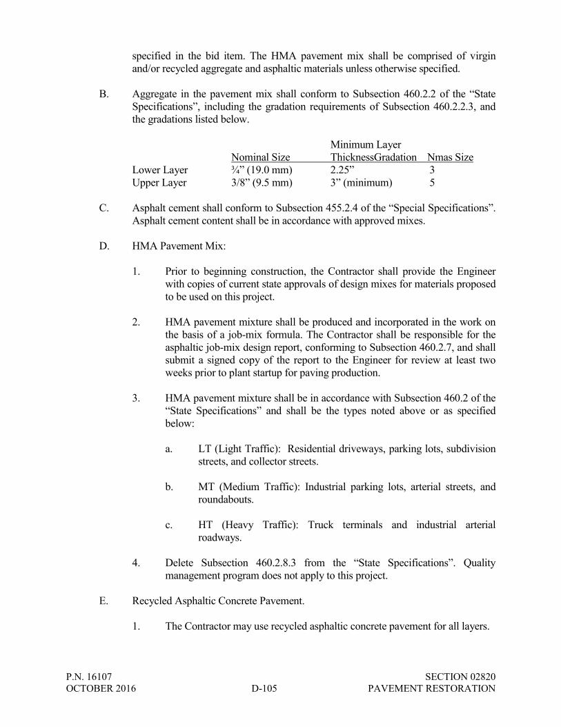
P.N. 16107 SECTION 02820 OCTOBER 2016 D-105 PAVEMENT RESTORATION
specified in the bid item. The HMA pavement mix shall be comprised of virgin and/or recycled aggregate and asphaltic materials unless otherwise specified.
B. Aggregate in the pavement mix shall conform to Subsection 460.2.2 of the “State
Specifications”, including the gradation requirements of Subsection 460.2.2.3, and the gradations listed below.
Minimum Layer Nominal Size ThicknessGradation Nmas Size Lower Layer ¾” (19.0 mm) 2.25” 3 Upper Layer 3/8” (9.5 mm) 3” (minimum) 5 C. Asphalt cement shall conform to Subsection 455.2.4 of the “Special Specifications”.
Asphalt cement content shall be in accordance with approved mixes. D. HMA Pavement Mix:
1. Prior to beginning construction, the Contractor shall provide the Engineer with copies of current state approvals of design mixes for materials proposed to be used on this project.
2. HMA pavement mixture shall be produced and incorporated in the work on
the basis of a job-mix formula. The Contractor shall be responsible for the asphaltic job-mix design report, conforming to Subsection 460.2.7, and shall submit a signed copy of the report to the Engineer for review at least two weeks prior to plant startup for paving production.
3. HMA pavement mixture shall be in accordance with Subsection 460.2 of the
“State Specifications” and shall be the types noted above or as specified below:
a. LT (Light Traffic): Residential driveways, parking lots, subdivision
streets, and collector streets. b. MT (Medium Traffic): Industrial parking lots, arterial streets, and
roundabouts. c. HT (Heavy Traffic): Truck terminals and industrial arterial
roadways.
4. Delete Subsection 460.2.8.3 from the “State Specifications”. Quality management program does not apply to this project.
E. Recycled Asphaltic Concrete Pavement.
1. The Contractor may use recycled asphaltic concrete pavement for all layers.

P.N. 16107 SECTION 02820 OCTOBER 2016 D-106 PAVEMENT RESTORATION
a. The recycled pavement shall consist of a mix of salvaged asphaltic pavement materials, presently stockpiled for use by the Contractor, and the required amounts of aggregate and asphalt cement. The recycled pavement shall be in accordance with a State approved mix calculated for the stockpiled material and comply with Section 460 of the “State Specifications”. The Contractor shall submit a copy of the job-mix formula to the Engineer.
F. Tack coat:
1. Material shall be an asphalt emulsion, conforming to Subsection 455.2.5 of the “State Specifications”, diluted with an equal amount of water and applied at a rate of 0.025 to 0.05 gallons per square yard or at a rate required to effectively bond the overlaying material.
2. Contractor shall prime (tack) the newly placed asphaltic pavement if it is
more than 3 hours between the base course and surface course; surfaces and edges of existing asphaltic pavement and surfaces and edges of existing concrete pavement immediately prior to placement of bituminous concrete pavement.
3. Contractor shall furnish the Engineer official receipts indicating the gallons
of bituminous tack coat used for each road. 2.03 CONCRETE PAVEMENT
A. Concrete pavement shall comply with Section 415 of the “State Specifications”, as modified below:
1. Concrete shall be Grade A, air entrained and shall conform to Section 415 of
the “State Specifications,” and in particular meet the following requirements:
Minimum cement content – sack per cubic yard 6.0 Compressive strength after 28 days cured 3,500 psi Maximum amount of water per sack of cement 6.0 gallons Size of coarse aggregate required No. 1 plus No. 2 Slump 2.5 inches or less Air Content 4.5% - 7.5% No admixtures (flyash, etc.)
2. Curing membrane meeting the requirements for Type 2 of the “STANDARD
SPECIFICATIONS FOR LIQUID MEMBRANE FORMING COMPOUNDS FOR CURING CONCRETE AASHTO DESIGNATION M148” shall be used to cover all finished concrete.

P.N. 16107 SECTION 02820 OCTOBER 2016 D-107 PAVEMENT RESTORATION
3. All concrete surfaces poured after September 1st shall be cured with “Sealtight Line – Seal White,” curing and anti-spalling compound manufactured by W.R. Meadows, Inc. or approved equal.
2.04 TRAFFIC BOND
A. Traffic bond for restoring graveled surfaces shall conform to Section 304 of the State Specifications.
2.05 PAVEMENT MARKING
A. Pavement marking material shall be epoxy conforming to Subsection 646.2.4.
PART 3 - EXECUTION 3.01 SAW-CUTTING PAVEMENTS
A. The edges of trenches crossing road pavements and driveways shall be saw-cut in neat straight lines, with no zigzags, perpendicular to the street or driveway centerline. All concrete and asphalt pavements, shoulders and driveways shall be saw-cut to a minimum depth of three (3) inches prior to being shattered and removed. Where concrete pavements are covered with an asphalt overlay, both the asphalt and concrete shall be saw-cut. Pavements shall be saw-cut in neat straight lines perpendicular or parallel to the road centerline to produce a clean joint for pavement restoration. If the saw-cut edge is damaged during construction, the Contractor shall saw-cut the pavement again immediately prior to paving.
B. All concrete and asphalt pavements within state highway right-of-ways shall be
saw-cut full depth prior to being shattered and removed.
C. The saw-cut shall be made through the widest point of damaged pavement. D. Concrete Pavement.
1. If the saw-cut edge of a trench through a concrete pavement outside of
state highway right-of-ways is closer than 4 feet to an existing joint or pavement edge, the pavement shall be removed and replaced to such joint or pavement edge.
2. State Highways.
a. A minimum width of 10 feet of concrete pavement shall be removed and replaced on state highways.
b. If the saw-cut edge of a trench through a concrete pavement within
a state highway right-of-way is closer than 10 feet to an existing

P.N. 16107 SECTION 02820 OCTOBER 2016 D-108 PAVEMENT RESTORATION
joint or pavement edge, the pavement shall be removed and replaced to such joint or pavement edge.
3.02 TEMPORARY SURFACING
A. The Contractor shall provide at least a temporary bituminous resurfacing of all
arterial or collector street pavement within two weeks of completion and backfill of sewer that required the removal of all or part of such arterial or collector street pavement. The replacement of the pavement shall not be delayed due to any service lateral construction on the segment of sewer and/or water main in the arterial or collector street pavement area that the Contractor may have remaining after the two-week period elapses.
B. Cold Patch.
1. The Contractor may be required to place a temporary surface over openings made in paved traffic lanes. Except when the pavement is to be replaced before the opening of the cut to traffic, the fill above the bottom of the paving slab shall be made with suitable material well tamped into place and this fill shall be topped with a minimum of at least 3" of bituminous mixture which is suitable to maintain the opening in good condition until permanent restoration can be made. The crown of the temporary restorations shall not exceed one inch above the adjoining pavement. The Contractor shall exercise special care in making such restorations and must maintain such restorations in safe travelling condition until such time as permanent restorations are made. In the event it becomes necessary for City forces to provide emergency maintenance of the Contractor's trenches, the cost of such work shall be billed to the Contractor. The asphalt which is used shall be in accordance with the specifications. If in the judgment of the City Engineer, it is not expedient to replace the pavement over any cut or excavation made in the street upon completion of the work under contract by reason of the looseness of the earth or weather conditions he may direct the Contractor to lay a temporary pavement of suitable material designated by him over such cut or excavation and maintain it until such time as the repair of the original pavement may be properly made.
3.03 CRUSHED LIMESTONE BASE COURSE
A. Crushed limestone base course shall be constructed in accordance with Section 305 of the “State Specifications”, and in kind. The Contractor shall furnish and place base material, in kind, as required to construct the base to grade. 1. Moisture Content.
a. Base material shall have a maximum moisture content of seven (7) percent before being weighed. Moisture content in excess of 7 percent will be deducted from the measured weight. Moisture content will be expressed as a percent of dry weight.

P.N. 16107 SECTION 02820 OCTOBER 2016 D-109 PAVEMENT RESTORATION
B. Standard Compaction. 1. Crushed limestone base course shall be compacted in accordance with
Subsection 207.3.6.2 of the “State Specifications” for standard compaction, as modified below.
a. Crushed limestone base course shall be placed and compacted in two
(2) or more layers in accordance with Section 305.3 of the “State Specifications”. Compacted layers shall be 6 inches or less, unless the Engineer approves thicker layers.
b. Moisture shall be added by tank wagon as required for maximum
compaction. c. Standard compaction shall consist of compacting each layer of the
base course to the degree that no further appreciable consolidation is evidenced under the action of the compaction equipment.
d. Compaction shall be performed by specialized compaction
equipment including tamping rollers, pneumatic tire rollers, vibratory rollers or other approved compaction equipment.
C. The Owner requires inspection of the base course before the asphalt and concrete
can be placed. The finished stone base elevation shall be above the approved final subgrade ± 0.10 foot. The gravel base shall be dry before the first layer of asphalt or concrete can be placed.
D. The Contractor responsible for the base course installation shall notify the
Engineer for inspection.
3.04 PERMANENT SURFACING – ASPHALT
A. Existing asphaltic pavement shall be replaced “in kind” except where the existing pavement thickness is less than the following minimum pavement thickness(es). Then the minimum pavement section shall be placed.
1. 8 inches of dense graded base and 4 inches of asphaltic concrete
pavement. The pavement shall consist of a minimum 1-3/4 inch thick upper layer and a minimum 2-1/4 inch thick lower layer.
B. Binder Course
1. Binder course construction shall be placed in one (1) lift. Construction shall be in accordance with Section 460 of the “State Specifications”.
2. The binder course shall be swept and all vegetation removed prior to
laying of any material.

P.N. 16107 SECTION 02820 OCTOBER 2016 D-110 PAVEMENT RESTORATION
C. Surface Course and Tack Coat:
1. A bituminous concrete surface course shall be constructed over the bituminous concrete binder course. Construction shall be in accordance with Section 450 and 460 of the “State Specifications”.
2. A tack coat shall be applied to the surface of the binder course in all restoration areas. Apply the tack coat the same day that the next layer is placed.
3. For compaction of the surface follow Section 465 of the “State
Specifications.” 4. Maximum variations:
a. 1/8 inch across a 5 foot straight edge. b. Thickness: Within 1/4 inch of design. c. Finish elevation: Within 1/4 inch of design.
5. Temperatures:
a. The asphalt delivered to the job site shall arrive at a temperature of 275 degrees plus or minus 25 degrees. Any truck loads which do not meet this requirement shall be rejected.
b. All asphalt shall be placed at a temperature of 250°F or higher. c. Asphaltic pavement shall not be placed when the air temperature in
the shade is less than 35°F unless approved by the Engineer. d. Remove Subsections 450.3.2.1, 450.3.2.1(4), and 450.3.2.1(5) of
the “State Specification” and replace with the following:
“If the Engineer allows placing asphaltic mixtures below the specified minimum temperature, either at the Contractor’s request or to complete the work to the stage the contract requires, the work will be performed at the Contractor’s risk. Final inspection of the HMA paving or asphaltic surfacing work will be deferred until May of the following year. Before final acceptance, restore all pavement damage or defects the Engineer attributes to temperature or other weather conditions. Repair or replace areas of pavement as identified by the Engineer.”
6. Prior to placing asphaltic surface course, all required corrections of filling
potholes, sags, and depressions shall be made.

P.N. 16107 SECTION 02820 OCTOBER 2016 D-111 PAVEMENT RESTORATION
7. In the event of sudden or impending rain, material in transit will be permitted to be laid at the Contractor’s risk providing the pavement is free of standing water and the proper temperature of the asphalt is maintained. Approval to unload the trucks in transit in no way relax the requirements of quality, density, or smoothness of the asphalt being placed.
8. All rolling shall be performed during daylight hours or as approved by the Engineer.
D. Pavement Compaction.
1. All pavements shall be built in accordance with the Maximum Density Method per Subsection 460.3.3 of “State Specifications”. The maximum specific gravity value shall be indicated on the asphaltic job-mix design report.
2. Pavements shall be compacted to a density not less than that shown in the table below:
Minimum Required Density
LOCATION LAYER PERCENT OF TARGET LT, MT HT SMA
Traffic Lanes (1) Lower Upper
91.5 (2) 91.5
92.0 (2) 92.0
94.0 94.0
Shoulders and Appurtenances
Lower Upper
89.5 90.5
89.5 90.5
91.0 (3) 91.0 (3)
(1) Included parking lanes as determined by the Engineer. (2) Minimum reduced by 2 percent for ˂3 million ESALs and one percent for ˃3
million ESALs, when the first lift of lower layer constructed on crushed limestone base course or recycled base courses.
(3) Minimum density will be 94.0 when the shoulders are paved integrally with the mainline pavement.
3. Delete Subsection 460.5.2.3 from the “State Specifications”. Pavement density
incentives do not apply to this project. 4. The Contractor shall verify degree of compaction and submit a report to the
Engineer as to date paved, date tested, location, and degree of compaction. All costs for the tests and report shall be included in the unit price(s) for other items.
E. Permanent Pavement Restoration Timetable.
1. Permanent asphaltic pavement shall be placed in accordance with the
requirements of Subsection 450.3 and concrete pavement shall be placed
P.N. 16107 SECTION 02820 OCTOBER 2016 D-112 PAVEMENT RESTORATION
in accordance with the requirements of Subsection 415.3.16 of the “State Specifications”.
2. Weather permitting, permanent pavement replacement shall be completed
within 30 calendar days after completing utility construction work or within the time allowed in the Agreement.
3. Permanent pavement replacement work in areas constructed during winter
months shall be completed by the following June 1st. All pavement replacement in areas constructed after June 1st shall be completed in accordance with Paragraphs 1 and 2, above.
F. Trench Surface Maintenance.
1. The Contractor’s attention is directed to Section 2.6.16 of the “Standard
Specifications”, requiring the Contractor to maintain trench surfaces for the duration of the Contract and for one (1) year after acceptance.
G. Butt Joints.
1. The Contractor shall construct butt joints wherever the new pavement overlay butts up to existing pavements; including at intersecting streets, project ends and as shown on the Drawings.
2. Butt joints may be constructed by removing a section of pavement or by
milling or grinding down 1-1/2 inches of pavement. Saw cuts shall be in neat straight lines at right angles to the street.
3.05 PERMANENT SURFACING – CONCRETE
A. Existing concrete pavement shall be replaced “in kind” except where the existing pavement thickness is less than the following minimum pavement thickness(es). Then the minimum pavement section shall be placed.
1. 8 inches of dense graded base and 7 inches of concrete pavement.
B. Concrete pavement shall be constructed in accordance with Sections 405, 415 and 501 of the “State Specifications.”
C. Longitudinal joints shall be constructed in accordance with Section 415.3.7 of the “State Specifications” in the location shown on the Drawings.
E. Transverse joints shall be constructed in accordance with Section 415.3.7 of the “State Specifications” in the locations shown on the Drawings.
F. Where forms are used, forms shall be of equal height to the prescribed thickness of the concrete immediately in contact. They shall be free from warps and kinks and of sufficient strength and rigidity, when staked, to resist pressure or load to which they

P.N. 16107 SECTION 02820 OCTOBER 2016 D-113 PAVEMENT RESTORATION
may be subjected. The Contractor shall have a sufficient quantity of forms to set at least 200 lineal feet in advance of placing concrete.
1. Kinds of Forms – Metal forms shall be used upon all standard mainline work. Only in special cases such irregular shapes and shirt sections will wood forms be permitted.
2. Metal Forms – Metal forms shall be of substantial section, having a flat
top surface not less than 1-3/4 inches wide, and shall be equipped with devices to hold them to proper grade and alignment during the consolidation and finishing of the concrete. Form sections shall be tightly joined by a locking device to prevent movement in any direction.
3. Wood Forms – Wood forms when used for special work shall be
commercial two inch surfaced plank. Lumber of less thickness will be permitted only on irregular shapes and short curves.
4. Separator Plates– Separator plates for walk, curbs, and gutters shall be of
metal 5/16 inch thick. They shall be cut to the cross section of the work upon which they are used. Only straight plates shall be used.
5. Oiling Forms and Plates – All forms and plates shall be free from dirt and
mortar, and shall be oiled each time they are used.
G. Construction joints shall be constructed at the formed edges of all pavement slabs. Use cast-in-place tie bars in longitudinal construction joints between concrete pavement pours. Tie bars shall be epoxy coated No. 4 tie bars in accordance with Section 505.2.6 of the State Specifications. Tie bars shall be 24-inches in length (12-inches on each side of joint) at ½ the pavement depth and spaced 30-inches on center.
H. Sealing Joints. Before opening the pavement to traffic, the top of all joints shall be
thoroughly cleaned and filled to the surface of the slab with Joint Sealer. Joint sealing may be done by hand pouring pots or mechanical methods in such manner that its sealer will not be spilled on the surface of the concrete. Any excess shall be removed immediately. Sufficient sealer shall be poured into the joints so that the sealer is flush with the surface of the pavement when the work is completed. When filling joints on slopes, pouring shall start at the lowest point and progress toward the high point. Traffic shall not be permitted over the poured joint until the sealer has hardened sufficiently to resist pickup.
I. Condition for Placing Concrete. Just before concrete is placed, the subgrade shall
be sprinkled with sufficient water to thoroughly dampen it, but not enough to form muddy areas. An approved subgrade template shall be used continually between the mixer and the point where concrete is being placed. Contact surfaces of catch basins and manhole frames, or other fixed objects within the pavement area, shall be brushed clean before the concrete is placed.

P.N. 16107 SECTION 02820 OCTOBER 2016 D-114 PAVEMENT RESTORATION
J. Placing mainline pavements must be placed using an approved self-propelled paving machine with vibration and strike-off abilities. No jitterbug bridge machines will be permitted to place the mainline portions of the pavement unless otherwise authorized by the Engineer.
K. All concrete shall receive a brush finish.
L. Concrete shall be cured by the Impervious Coating Method in accordance with
Subsection 415.3.12.2 of the “State Specifications”.
M. Pavement Ties.
1. All joints between existing and new pavements shall be constructed using tie bars conforming to Subsection 505.2.6 of the “State Specifications”.
3.06 RESTORATION OF GRAVELED SURFACES
A. The Contractor shall be required to restore all graveled surfaces to a drivable condition, which were removed for the underground installation with traffic bound granular materials. Materials and installation shall conform to Section 304 of the State Specifications.
3.07 PAVEMENT MARKING REPLACEMENT
A. Pavement markings shall be replaced in-kind in accordance with Section 646 of
the “State Specifications”. 3.08 PAVEMENT RESTORATION TIMETABLE
A. Weather permitting, pavement replacement shall be completed within 30 calendar days after completing utility construction work.
B. Pavement replacement work in areas constructed during winter months shall be
completed by the substantial completion date.
END OF SECTION

P.N. 16107 SECTION 02830 OCTOBER 2016 D-115 LAWN RESTORATION
SECTION 02830
LAWN RESTORATION PART 1 – GENERAL
The requirements of the Contract Documents, including the General Conditions, the Supplementary Conditions and Division I - General Requirements apply to this Section except as modified herein.
1.01 DESCRIPTION
A. The contractor shall repair and reseed all established lawns damaged during the course of construction to a condition equal to or better than the condition at the commencement of his work.
B. The Work to be performed under this section includes the furnishing of all labor,
materials, parts, tools, equipment, supervision and incidentals necessary for the restoration of disturbed lawn areas located within the project limits as designated on the Drawings.
PART 2 – MATERIALS 2.01 SALVAGED TOPSOIL
A. All salvaged topsoil materials, processing and placement shall conform to Section 625 of the State Specifications.
B. The Contractor has the option to use topsoil instead of salvaged topsoil; however, no adjustment in unit price will be allowed for changes in use of salvaged topsoil or topsoil.
2.02 SEED
A. All seed mixtures shall meet the requirements of Sections 630.2.1.2 and 630.2.1.3 of the “State Specifications” for purity, germination, and inoculation. The Contractor shall supply the vendor’s certificate to the Engineer prior to seeding in order to verify that the seed used meets the project specifications.
B. The seed shall be as specified and delivered to the project site in tagged bags with
certified labels indicating the percentage of purity and germination. The seed shall have been tested within one (1) year prior to the date of seeding and shall conform to the latest State and Federal seed laws.
C. All grass seed shall be fresh, clean, new-crop seed. Grass seed shall not have been
exposed to weather prior to delivery to the project site, and after delivery, until used, it shall be completely protected from the weather at all times. It shall not be
P.N. 16107 SECTION 02830 OCTOBER 2016 D-116 LAWN RESTORATION
sotred in direct contact with the ground or in areas of excessive heat, cold, or moisture.
D. Grass seed shall meet the requirements of Subsection 630.2.1.5.1.1.1 (Seed Mixture
No. 40). E. The Contractor shall furnish all empty seed bags to the Owner.
2.03 FERTILIZER
A. Fertilizer shall comply with Section 629 of the “State Specifications”. 2.04 MULCH
A. Mulching shall comply with Section 627 of the “State Specifications”. 2.05 TACKIFIER
A. Select tackifier from the WisDOT erosion control product acceptability list (PAL).
2.06 EROSION MAT
A. Class I Urban erosion mat utilizing all biodegradable materials.
PART 3 – CONSTRUCTION
3.01 SALVAGED TOPSOIL REPLACEMENT
A. At the completion of grading activities, the Contractor shall spread salvaged topsoil to a minimum uniform depth of 4 inches over all disturbed areas and as shown on the Drawings. All sticks, stones and other debris in excess of 2-inches in diameter shall be removed.
B. Harrowing or disking or both will be required as necessary to assist in breaking
down clods and lumps and to provide a uniform texture to this soil.
C. All Work shall be trimmed, shaped and restored to the finished grade by means of a grader and other equipment, supplemented by hand work where necessary to produce smooth surfaces and slopes and uniform sections.
3.02 HYDROSEEDING (SEED, FERTILIZER, MULCH, AND TACKIFIER)
A. Mix seed, fertilizer, mulch, and tackifier together with water in a hydroseeder machine and apply in a one step process in accordance with Method B (Tackifier) of Subsection 627.3.2.2 of the “State Specifications.”
P.N. 16107 SECTION 02830 OCTOBER 2016 D-117 LAWN RESTORATION
B. The hydroseeder machine shall have a built-in agitation system and operating capacity sufficient to agitate, suspend, and homogeneously mix a slurry containing sufficient materials to meet or exceed minimum application rates. All materials shall be compatible with the hydroseeding process.
C. Replace cover by means of seeding with grass seed at the rate of not less than six
pounds per thousand square feet on leveled topsoil. 3.03 EROSION MAT
A. The contractor shall place Class I Urban erosion mat on all areas of the restored lawns and ditches.
3.04 SEED
A. Sow grass seed by hydroseeding at a rate of four (4) pounds per 1,000 square feet.
3.05 FERTILIZER
A. Apply Type A fertilizer at 7 pounds per 1,000 square feet. 3.06 MULCH
A. All seeded areas shall be mulched in accordance with Method B (Tackifier) of Subsection 627.3.2.2 of the “State Specifications.”
3.07 LAWN RESTORATION TIMETABLE
A. Seeding may be done at any time during the growing season when soil conditions are suitable.
B. All lawn restoration work shall be completed by the final completion date.
3.08 MAINTENANCE AND MONITORING
A. The Contractor shall maintain all seeded areas performed under this contract which includes the destroying of noxious weeds within the seeded areas by cutting or by other means and prevent the weed plants from maturing to the bloom or flower stage. The term “noxious weeds” as defined here shall constitute plant life other than those included within the seed mixture specified. The Contractor shall maintain and monitor seeded areas upon initial seeding and throughout the correction period to assure uniform and consistent growth of the specified seed as determined by the Owner. The cost for providing maintenance will be considered incidental to other bid items.
P.N. 16107 SECTION 02830 OCTOBER 2016 D-118 LAWN RESTORATION
3.09 WATERING
A. The Contractor shall be responsible for daily watering all restored areas for a minimum of three weeks, until established dense growth and first mow, following the final completion.
END OF SECTION
P.N. 16107 SECTION 02900 OCTOBER 2016 D-119 TRAFFIC CONTROL AND PROTECTION
SECTION 02900
TRAFFIC CONTROL AND PROTECTION PART 1 – GENERAL
The requirements of the Contract Documents, including the General Conditions the Supplementary Conditions and Division I - General Requirements apply to this Section except as modified herein.
1.01 DESCRIPTION
A. The Contractor shall provide all traffic control as is necessary to assure the safety of
the public. PART 2 – PRODUCTS 2.01 MATERIALS
A. All equipment necessary to complete this item shall be in accordance with all
applicable parts of the Wisconsin Manual on Uniform Traffic Control Devices for Streets, and the requirements of the OAK CREEK WATER AND SEWER UTILITY and the City of Oak Creek.
PART 3 – EXECUTION 3.01 INSTALLATION
A. The Contractor is responsible for obtaining a Public Right-of-Way Excavation
Permit from the City of Oak Creek to complete work within the right-of-way, and to provide a Traffic Control Plan for review and approval by the ENGINEER as stated in Section 01300 – Submittals. A copy of the blank permit application is found in the Appendix of this Project Manual and can also be found online at http://www.oakcreekwi.org/discover-oak-creek/forms-permits/.
B. At least one lane of traffic must be maintained and open to through traffic at all points in time. No road shall be closed without approval by the Engineer.
C. The Contractor shall obtain, erect, maintain and remove all signs, barricades, flagmen and other traffic control devices as may be necessary for the purpose of regulating, warning, or guiding traffic. The Contractor shall patrol the work site on a daily basis to ensure that all traffic control devices are properly located and visible to traffic.
P.N. 16107 SECTION 02900 OCTOBER 2016 D-120 TRAFFIC CONTROL AND PROTECTION
D. As a minimum, the provisions of the FHWA “Manual for Uniform Traffic Control Devices” shall be met. All traffic control procedures shall be subject to the approval of the ENGINEER.
E. The Contractor shall provide the Engineer the names and telephone number of two
(2) individuals who will be available 24 hours a day, 7 days a week, to respond to calls from the Engineer or Owner to correct traffic control deficiencies.
F. Temporary traffic control devices shall include barricades, barrels, warning lights,
flaggers, signs and posts required to direct vehicles and pedestrians in accordance with Section 643.2 of the State Specifications.
G. The Contractor shall be responsible for maintaining, up-righting, sandbagging and
operating temporary traffic signs. The Contractor shall secure restricted areas at the end of the workday. All temporary traffic control devices shall be highly visible and in good condition.
H. The Contractor shall be responsible for the erection and maintenance of all drums,
barricades, lights and signs necessary for public safety and convenience in accordance with all applicable requirements. In general, all hazards within the limits of the work or on detours around the work must be marked with well-painted, well-maintained drums, barricades, reflectors, electric lights, flashers and warning and directional signs in sufficient quantity and size adequate to protect life and property. These safeguards shall be moved, changed, increased or removed as required during the progress of the work to meet changing conditions. Homemade signs will not be allowed.
I. When a street is closed to through traffic, barricades shall be placed at the adjacent
intersections as well as at the location of the obstruction. Detour signs shall be attached to the barricades at the adjacent intersections. Detour signs shall be adequately illuminated and/or reflectorized so as to be clearly visible at all times.
J. The ENGINEER reserves the right to require that “snow fence” be installed at
locations where streets are closed for the full width of the roadway. Barricades shall be maintained in rigidly assembled condition. All warning devices shall be kept clean and in good repair so as to be readily discernible at all times.
K. Whenever the Contractor's operations obstruct or endanger a traffic lane, and no
marked detour has been provided, the Contractor shall furnish a flagman to direct traffic through or around the congested area. The ENGINEER shall have the right to require additional flagmen, as he may deem necessary.
L. Adequate protection shall be provided around all openings wherever required to
safeguard the Work or the public. All openings and surface obstructions shall be protected with drums, barricades, signs, lights and warning devices in accordance with local requirements.
P.N. 16107 SECTION 02900 OCTOBER 2016 D-121 TRAFFIC CONTROL AND PROTECTION
M. The Contractor shall notify the applicable police and fire departments if one or
more lanes of traffic is to be obstructed and any time during construction. N. The Contractor shall make provisions for garbage collection. O. The Contractor shall make provisions to provide full time access to residences with
handicapped persons, nursing and retirement homes, hospitals, and other facilities unless other arrangements are made and approved by the Owner.
P. The Contractor shall provide full time access to businesses and industries. Access
may be provided by constructing temporary drives or other accepted methods approved by the Owner.
Q. The Contractor is responsible for insuring that mail can be delivered to properties
affected by the construction. If the Contractor’s operations restrict or prohibit mail delivery, the Contractor shall take measures to provide alternated methods for mail pickup. These methods should be coordinated and approved by the USPS.
R. When driveway access is to be blocked, the Contractor shall be responsible for
notifying all affected property owners at east 24 hours prior to restricting access. The Contractor shall provide temporary ramps at all driveways to provide access during road construction.
S. If parking lanes will be restricted, the Contractor shall furnish and install parking
restriction signs at least 36 hours in advance of the restriction. The Contractor shall indicate the applicable days of the parking restriction on the sign.
T. The Contractor must allow for local traffic and must maintain access for emergency
vehicles at all times.
END OF SECTION

APPENDIX
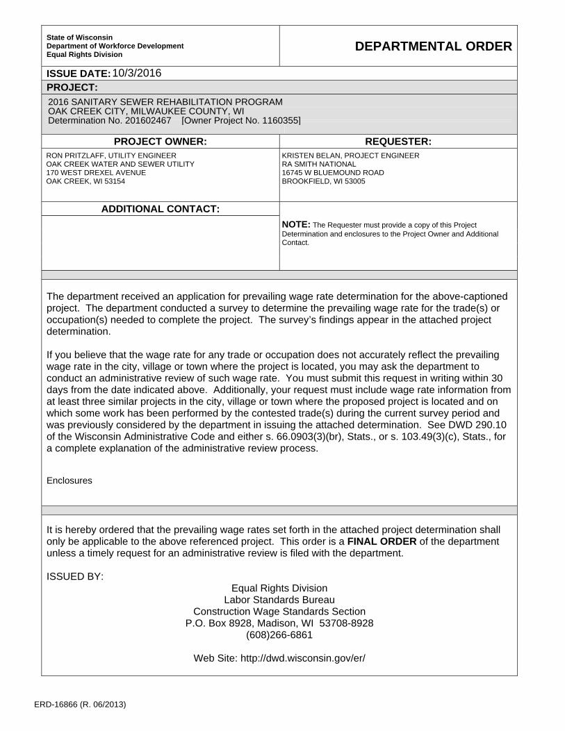
ERD-16866 (R. 06/2013)
State of Wisconsin Department of Workforce Development Equal Rights Division
DEPARTMENTAL ORDER
ISSUE DATE:
PROJECT:
PROJECT OWNER: REQUESTER:
ADDITIONAL CONTACT:
The department received an application for prevailing wage rate determination for the above-captioned project. The department conducted a survey to determine the prevailing wage rate for the trade(s) or occupation(s) needed to complete the project. The survey’s findings appear in the attached project determination. If you believe that the wage rate for any trade or occupation does not accurately reflect the prevailing wage rate in the city, village or town where the project is located, you may ask the department to conduct an administrative review of such wage rate. You must submit this request in writing within 30 days from the date indicated above. Additionally, your request must include wage rate information from at least three similar projects in the city, village or town where the proposed project is located and on which some work has been performed by the contested trade(s) during the current survey period and was previously considered by the department in issuing the attached determination. See DWD 290.10 of the Wisconsin Administrative Code and either s. 66.0903(3)(br), Stats., or s. 103.49(3)(c), Stats., for a complete explanation of the administrative review process. Enclosures
It is hereby ordered that the prevailing wage rates set forth in the attached project determination shall only be applicable to the above referenced project. This order is a FINAL ORDER of the department unless a timely request for an administrative review is filed with the department. ISSUED BY:
Equal Rights Division Labor Standards Bureau
Construction Wage Standards Section P.O. Box 8928, Madison, WI 53708-8928
(608)266-6861
Web Site: http://dwd.wisconsin.gov/er/
RON PRITZLAFF, UTILITY ENGINEEROAK CREEK WATER AND SEWER UTILITY170 WEST DREXEL AVENUEOAK CREEK, WI 53154
KRISTEN BELAN, PROJECT ENGINEERRA SMITH NATIONAL16745 W BLUEMOUND ROADBROOKFIELD, WI 53005
NOTE: The Requester must provide a copy of this ProjectDetermination and enclosures to the Project Owner and AdditionalContact.
10/3/2016
2016 SANITARY SEWER REHABILITATION PROGRAMOAK CREEK CITY, MILWAUKEE COUNTY, WIDetermination No. 201602467 [Owner Project No. 1160355]

2016 SANITARY SEWER REHABILITATION PROGRAM
PROJECT NO: 1160355
Contractors are responsible for correctly classifying their workers. Either call the Department ofWorkforce Development (DWD) with trade or classification questions or consult DWD’s Dictionary ofOccupational Classifications & Work Descriptions on the DWD website at:dwd.wisconsin.gov/er/prevailing_wage_rate/Dictionary/dictionary_main.htm.
Time and one-half must be paid for all hours worked:- over 10 hours per day on prevailing wage projects- over 40 hours per calendar week- Saturday and Sunday- on all of the following holidays: January 1; the last Monday in May; July 4;
the 1st Monday in September; the 4th Thursday in November; December25;
- The day before if January 1, July 4 or December 25 falls on a Saturday;- The day following if January 1, July 4 or December 25 falls on a Sunday.
Apply the time and one-half overtime calculation to whichever is higher between the Hourly Basic Ratelisted on this project determination or the employee's regular hourly rate of pay. Add any applicablePremium or DOT Premium to the Hourly Basic Rate before calculating overtime.
A DOT Premium (discussed below) may supersede this time and one-half requirement.
When a specific trade or occupation requires a future increase, you MUST add the full hourly increaseto the "TOTAL" on the effective date(s) indicated for the specific trade or occupation.
If indicated for a specific trade or occupation, the full amount of such pay MUST be added to the"HOURLY BASIC RATE OF PAY" indicated for such trade or occupation, whevenever such pay isapplicable.
This premium only applies to highway and bridge projects owned by the Wisconsin Department ofTransportation and to the project type heading "Airport Pavement or State Highway Construction." DONOT apply the premium calculation under any other project type on this determination.
Pay apprentices a percentage of the applicable journeyperson's hourly basic rate of pay and hourlyfringe benefit contributions specified in this determination. Obtain the appropriate percentage fromeach apprentice’s contract or indenture.
Subjourney wage rates may be available for some of the trades or occupations indicated below withthe exception of laborers, truck drivers and heavy equipment operators. Any employer interested inusing a subjourney classification on this project MUST complete Form ERD-10880 and request theapplicable wage rate from the Department of Workforce Development PRIOR to using the subjourneyworker on this project.
PREVAILING WAGE RATE DETERMINATIONIssued by the State of Wisconsin
Department of Workforce DevelopmentPursuant to s. 66.0903, Wis. Stats.
Issued On: 10/3/2016
DETERMINATION NUMBER: 201602467
EXPIRATION DATE: Prime Contracts MUST Be Awarded or Negotiated On Or Before4/1/2017. If NOT, You MUST Reapply.
PROJECT NAME:
PROJECT LOCATION: OAK CREEK CITY, MILWAUKEE COUNTY, WI
CONTRACTING AGENCY: OAK CREEK WATER AND SEWER UTILITY
CLASSIFICATION:
OVERTIME:
FUTURE INCREASE:
PREMIUM PAY:
DOT PREMIUM:
APPRENTICES:
SUBJOURNEY:
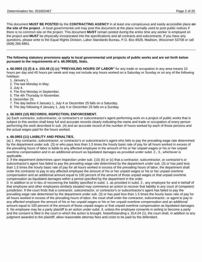
This document MUST BE POSTED by the CONTRACTING AGENCY in at least one conspicuous and easily accessible place onthe site of the project . A local governmental unit may post this document at the place normally used to post public notices ifthere is no common site on the project. This document MUST remain posted during the entire time any worker is employed onthe project and MUST be physically incorporated into the specifications and all contracts and subcontracts. If you have anyquestions, please write to the Equal Rights Division, Labor Standards Bureau, P.O. Box 8928, Madison, Wisconsin 53708 or call(608) 266-6861.
The following statutory provisions apply to local governmental unit projects of public works and are set forth belowpursuant to the requirements of s. 66.0903(8), Stats.
s. 66.0903 (1) (f) & s. 103.49 (1) (c) "PREVAILING HOURS OF LABOR" for any trade or occupation in any area means 10hours per day and 40 hours per week and may not include any hours worked on a Saturday or Sunday or on any of the followingholidays:
1. January 1.2. The last Monday in May.3. July 4.4. The first Monday in September.5. The 4th Thursday in November.6. December 25.7. The day before if January 1, July 4 or December 25 falls on a Saturday.8. The day following if January 1, July 4 or December 25 falls on a Sunday.
s. 66.0903 (10) RECORDS; INSPECTION; ENFORCEMENT.(a) Each contractor, subcontractor, or contractor's or subcontractor's agent performing work on a project of public works that issubject to this section shall keep full and accurate records clearly indicating the name and trade or occupation of every personperforming the work described in sub. (4) and an accurate record of the number of hours worked by each of those persons andthe actual wages paid for the hours worked.
s. 66.0903 (11) LIABILITY AND PENALTIES.(a) 1. Any contractor, subcontractor, or contractor's or subcontractor's agent who fails to pay the prevailing wage rate determinedby the department under sub. (3) or who pays less than 1.5 times the hourly basic rate of pay for all hours worked in excess ofthe prevailing hours of labor is liable to any affected employee in the amount of his or her unpaid wages or his or her unpaidovertime compensation and in an additional amount as liquidated damages as provided under subd. 2., 3., whichever isapplicable.2. If the department determines upon inspection under sub. (10) (b) or (c) that a contractor, subcontractor, or contractor's orsubcontractor's agent has failed to pay the prevailing wage rate determined by the department under sub. (3) or has paid lessthan 1.5 times the hourly basic rate of pay for all hours worked in excess of the prevailing hours of labor, the department shallorder the contractor to pay to any affected employee the amount of his or her unpaid wages or his or her unpaid overtimecompensation and an additional amount equal to 100 percent of the amount of those unpaid wages or that unpaid overtimecompensation as liquidated damages within a period specified by the department in the order.3. In addition to or in lieu of recovering the liability specified in subd. 1. as provided in subd. 2., any employee for and in behalf ofthat employee and other employees similarly situated may commence an action to recover that liability in any court of competentjurisdiction. If the court finds that a contractor, subcontractor, or contractor's or subcontractor's agent has failed to pay theprevailing wage rate determined by the department under sub. (3) or has paid less than 1.5 times the hourly basic rate of pay forall hours worked in excess of the prevailing hours of labor, the court shall order the contractor, subcontractor, or agent to pay toany affected employee the amount of his or her unpaid wages or his or her unpaid overtime compensation and an additionalamount equal to 100 percent of the amount of those unpaid wages or that unpaid overtime compensation as liquidated damages.5. No employee may be a party plaintiff to an action under subd. 3. unless the employee consents in writing to become a partyand the consent is filed in the court in which the action is brought. Notwithstanding s. 814.04 (1), the court shall, in addition to anyjudgment awarded to the plaintiff, allow reasonable attorney fees and costs to be paid by the defendant.
Determination No. 201602467 Page 2 of 20
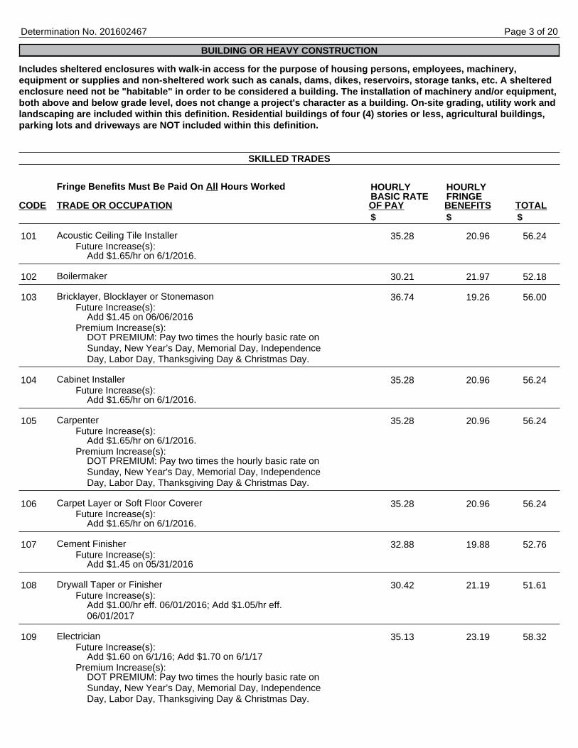
Includes sheltered enclosures with walk-in access for the purpose of housing persons, employees, machinery,equipment or supplies and non-sheltered work such as canals, dams, dikes, reservoirs, storage tanks, etc. A shelteredenclosure need not be "habitable" in order to be considered a building. The installation of machinery and/or equipment,both above and below grade level, does not change a project's character as a building. On-site grading, utility work andlandscaping are included within this definition. Residential buildings of four (4) stories or less, agricultural buildings,parking lots and driveways are NOT included within this definition.
Fringe Benefits Must Be Paid On All Hours Worked
CODE TRADE OR OCCUPATION OF PAY BENEFITS TOTAL
Acoustic Ceiling Tile InstallerFuture Increase(s):
Add $1.65/hr on 6/1/2016.
Boilermaker
Bricklayer, Blocklayer or StonemasonFuture Increase(s):
Add $1.45 on 06/06/2016Premium Increase(s):
DOT PREMIUM: Pay two times the hourly basic rate onSunday, New Year’s Day, Memorial Day, IndependenceDay, Labor Day, Thanksgiving Day & Christmas Day.
Cabinet InstallerFuture Increase(s):
Add $1.65/hr on 6/1/2016.
CarpenterFuture Increase(s):
Add $1.65/hr on 6/1/2016.Premium Increase(s):
DOT PREMIUM: Pay two times the hourly basic rate onSunday, New Year's Day, Memorial Day, IndependenceDay, Labor Day, Thanksgiving Day & Christmas Day.
Carpet Layer or Soft Floor CovererFuture Increase(s):
Add $1.65/hr on 6/1/2016.
Cement FinisherFuture Increase(s):
Add $1.45 on 05/31/2016
Drywall Taper or FinisherFuture Increase(s):
Add $1.00/hr eff. 06/01/2016; Add $1.05/hr eff.06/01/2017
ElectricianFuture Increase(s):
Add $1.60 on 6/1/16; Add $1.70 on 6/1/17Premium Increase(s):
DOT PREMIUM: Pay two times the hourly basic rate onSunday, New Year’s Day, Memorial Day, IndependenceDay, Labor Day, Thanksgiving Day & Christmas Day.
Determination No. 201602467
BUILDING OR HEAVY CONSTRUCTION
SKILLED TRADES
HOURLY HOURLYBASIC RATE FRINGE
$ $ $
101 35.28 20.96 56.24
102 30.21 21.97 52.18
103 36.74 19.26 56.00
104 35.28 20.96 56.24
105 35.28 20.96 56.24
106 35.28 20.96 56.24
107 32.88 19.88 52.76
108 30.42 21.19 51.61
109 35.13 23.19 58.32
Page 3 of 20
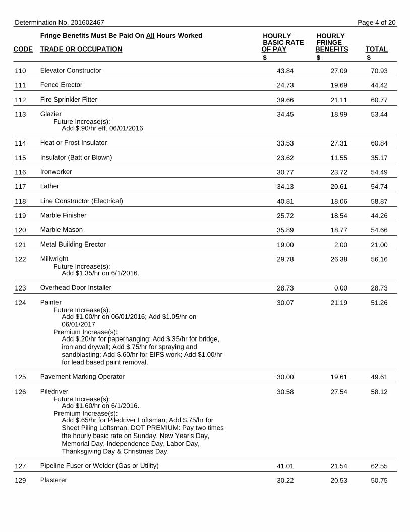
Fringe Benefits Must Be Paid On All Hours Worked
CODE TRADE OR OCCUPATION OF PAY BENEFITS TOTAL
Elevator Constructor
Fence Erector
Fire Sprinkler Fitter
GlazierFuture Increase(s):
Add $.90/hr eff. 06/01/2016
Heat or Frost Insulator
Insulator (Batt or Blown)
Ironworker
Lather
Line Constructor (Electrical)
Marble Finisher
Marble Mason
Metal Building Erector
MillwrightFuture Increase(s):
Add $1.35/hr on 6/1/2016.
Overhead Door Installer
PainterFuture Increase(s):
Add $1.00/hr on 06/01/2016; Add $1.05/hr on06/01/2017
Premium Increase(s):Add $.20/hr for paperhanging; Add $.35/hr for bridge,iron and drywall; Add $.75/hr for spraying andsandblasting; Add $.60/hr for EIFS work; Add $1.00/hrfor lead based paint removal.
Pavement Marking Operator
PiledriverFuture Increase(s):
Add $1.60/hr on 6/1/2016.Premium Increase(s):
Add $.65/hr for Piledriver Loftsman; Add $.75/hr forSheet Piling Loftsman. DOT PREMIUM: Pay two timesthe hourly basic rate on Sunday, New Year's Day,Memorial Day, Independence Day, Labor Day,Thanksgiving Day & Christmas Day.
Pipeline Fuser or Welder (Gas or Utility)
Plasterer
Determination No. 201602467
HOURLY HOURLYBASIC RATE FRINGE
$ $ $
110 43.84 27.09 70.93
111 24.73 19.69 44.42
112 39.66 21.11 60.77
113 34.45 18.99 53.44
114 33.53 27.31 60.84
115 23.62 11.55 35.17
116 30.77 23.72 54.49
117 34.13 20.61 54.74
118 40.81 18.06 58.87
119 25.72 18.54 44.26
120 35.89 18.77 54.66
121 19.00 2.00 21.00
122 29.78 26.38 56.16
123 28.73 0.00 28.73
124 30.07 21.19 51.26
125 30.00 19.61 49.61
126 30.58 27.54 58.12
127 41.01 21.54 62.55
129 30.22 20.53 50.75
Page 4 of 20
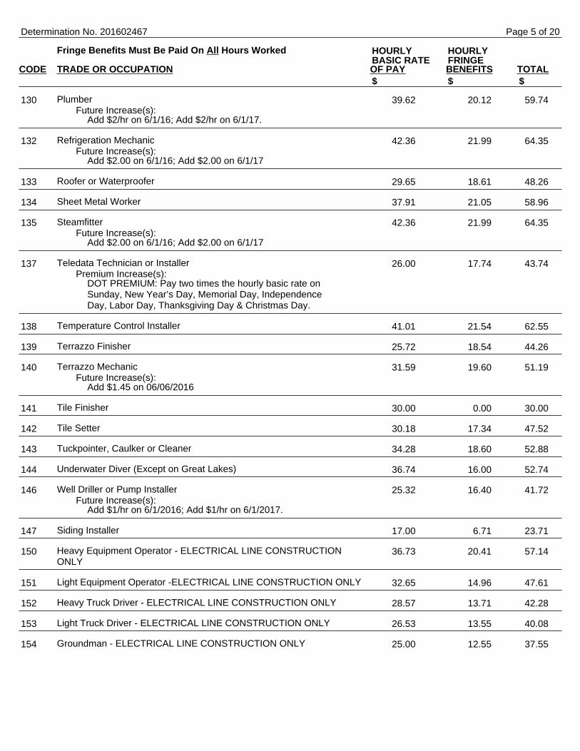
Fringe Benefits Must Be Paid On All Hours Worked
CODE TRADE OR OCCUPATION OF PAY BENEFITS TOTAL
PlumberFuture Increase(s):
Add $2/hr on 6/1/16; Add $2/hr on 6/1/17.
Refrigeration MechanicFuture Increase(s):
Add $2.00 on 6/1/16; Add $2.00 on 6/1/17
Roofer or Waterproofer
Sheet Metal Worker
SteamfitterFuture Increase(s):
Add $2.00 on 6/1/16; Add $2.00 on 6/1/17
Teledata Technician or InstallerPremium Increase(s):
DOT PREMIUM: Pay two times the hourly basic rate onSunday, New Year’s Day, Memorial Day, IndependenceDay, Labor Day, Thanksgiving Day & Christmas Day.
Temperature Control Installer
Terrazzo Finisher
Terrazzo MechanicFuture Increase(s):
Add $1.45 on 06/06/2016
Tile Finisher
Tile Setter
Tuckpointer, Caulker or Cleaner
Underwater Diver (Except on Great Lakes)
Well Driller or Pump InstallerFuture Increase(s):
Add $1/hr on 6/1/2016; Add $1/hr on 6/1/2017.
Siding Installer
Heavy Equipment Operator - ELECTRICAL LINE CONSTRUCTIONONLY
Light Equipment Operator -ELECTRICAL LINE CONSTRUCTION ONLY
Heavy Truck Driver - ELECTRICAL LINE CONSTRUCTION ONLY
Light Truck Driver - ELECTRICAL LINE CONSTRUCTION ONLY
Groundman - ELECTRICAL LINE CONSTRUCTION ONLY
Determination No. 201602467
HOURLY HOURLYBASIC RATE FRINGE
$ $ $
130 39.62 20.12 59.74
132 42.36 21.99 64.35
133 29.65 18.61 48.26
134 37.91 21.05 58.96
135 42.36 21.99 64.35
137 26.00 17.74 43.74
138 41.01 21.54 62.55
139 25.72 18.54 44.26
140 31.59 19.60 51.19
141 30.00 0.00 30.00
142 30.18 17.34 47.52
143 34.28 18.60 52.88
144 36.74 16.00 52.74
146 25.32 16.40 41.72
147 17.00 6.71 23.71
150 36.73 20.41 57.14
151 32.65 14.96 47.61
152 28.57 13.71 42.28
153 26.53 13.55 40.08
154 25.00 12.55 37.55
Page 5 of 20

Fringe Benefits Must Be Paid On All Hours Worked
CODE TRADE OR OCCUPATION OF PAY BENEFITS TOTAL
Single Axle or Two Axle
Three or More Axle
Articulated, Euclid, Dumptor, Off Road Material HaulerFuture Increase(s):
Add $1.60/hr on 5/30/2016.
Pavement Marking Vehicle
Truck Mechanic
Fringe Benefits Must Be Paid On All Hours Worked
CODE TRADE OR OCCUPATION OF PAY BENEFITS TOTAL
General Laborer
Asbestos Abatement Worker
Landscaper
Gas or Utility Pipeline Laborer (Other Than Sewer and Water)
Fiber Optic Laborer (Outside, Other Than Concrete Encased)
Railroad Track Laborer
Final Construction Clean-Up Worker
Determination No. 201602467
TRUCK DRIVERS
HOURLY HOURLYBASIC RATE FRINGE
$ $ $
201 34.47 18.70 53.17
203 20.00 18.19 38.19
204 33.02 19.15 52.17
205 20.00 18.19 38.19
207 20.00 18.19 38.19
LABORERS
HOURLY HOURLYBASIC RATE FRINGE
$ $ $
301 29.01 17.39 46.40
302 19.00 0.00 19.00
303 14.00 11.63 25.63
310 20.83 18.39 39.22
311 18.53 0.00 18.53
314 17.00 5.43 22.43
315 29.01 17.39 46.40
Page 6 of 20
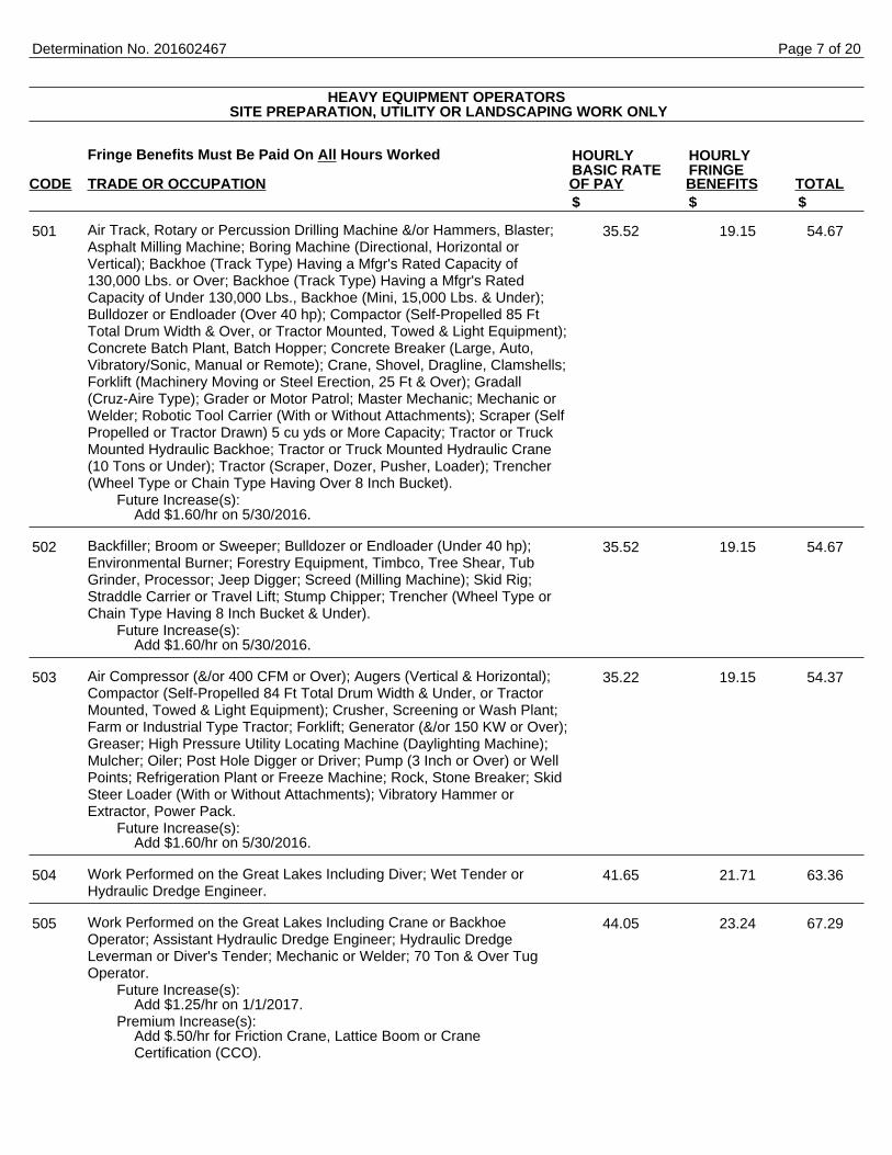
Fringe Benefits Must Be Paid On All Hours Worked
CODE TRADE OR OCCUPATION OF PAY BENEFITS TOTAL
Air Track, Rotary or Percussion Drilling Machine &/or Hammers, Blaster;Asphalt Milling Machine; Boring Machine (Directional, Horizontal orVertical); Backhoe (Track Type) Having a Mfgr's Rated Capacity of130,000 Lbs. or Over; Backhoe (Track Type) Having a Mfgr's RatedCapacity of Under 130,000 Lbs., Backhoe (Mini, 15,000 Lbs. & Under);Bulldozer or Endloader (Over 40 hp); Compactor (Self-Propelled 85 FtTotal Drum Width & Over, or Tractor Mounted, Towed & Light Equipment);Concrete Batch Plant, Batch Hopper; Concrete Breaker (Large, Auto,Vibratory/Sonic, Manual or Remote); Crane, Shovel, Dragline, Clamshells;Forklift (Machinery Moving or Steel Erection, 25 Ft & Over); Gradall(Cruz-Aire Type); Grader or Motor Patrol; Master Mechanic; Mechanic orWelder; Robotic Tool Carrier (With or Without Attachments); Scraper (SelfPropelled or Tractor Drawn) 5 cu yds or More Capacity; Tractor or TruckMounted Hydraulic Backhoe; Tractor or Truck Mounted Hydraulic Crane(10 Tons or Under); Tractor (Scraper, Dozer, Pusher, Loader); Trencher(Wheel Type or Chain Type Having Over 8 Inch Bucket).
Future Increase(s):Add $1.60/hr on 5/30/2016.
Backfiller; Broom or Sweeper; Bulldozer or Endloader (Under 40 hp);Environmental Burner; Forestry Equipment, Timbco, Tree Shear, TubGrinder, Processor; Jeep Digger; Screed (Milling Machine); Skid Rig;Straddle Carrier or Travel Lift; Stump Chipper; Trencher (Wheel Type orChain Type Having 8 Inch Bucket & Under).
Future Increase(s):Add $1.60/hr on 5/30/2016.
Air Compressor (&/or 400 CFM or Over); Augers (Vertical & Horizontal);Compactor (Self-Propelled 84 Ft Total Drum Width & Under, or TractorMounted, Towed & Light Equipment); Crusher, Screening or Wash Plant;Farm or Industrial Type Tractor; Forklift; Generator (&/or 150 KW or Over);Greaser; High Pressure Utility Locating Machine (Daylighting Machine);Mulcher; Oiler; Post Hole Digger or Driver; Pump (3 Inch or Over) or WellPoints; Refrigeration Plant or Freeze Machine; Rock, Stone Breaker; SkidSteer Loader (With or Without Attachments); Vibratory Hammer orExtractor, Power Pack.
Future Increase(s):Add $1.60/hr on 5/30/2016.
Work Performed on the Great Lakes Including Diver; Wet Tender orHydraulic Dredge Engineer.
Work Performed on the Great Lakes Including Crane or BackhoeOperator; Assistant Hydraulic Dredge Engineer; Hydraulic DredgeLeverman or Diver's Tender; Mechanic or Welder; 70 Ton & Over TugOperator.
Future Increase(s):Add $1.25/hr on 1/1/2017.
Premium Increase(s):Add $.50/hr for Friction Crane, Lattice Boom or CraneCertification (CCO).
Determination No. 201602467
HEAVY EQUIPMENT OPERATORS SITE PREPARATION, UTILITY OR LANDSCAPING WORK ONLY
HOURLY HOURLYBASIC RATE FRINGE
$ $ $
501 35.52 19.15 54.67
502 35.52 19.15 54.67
503 35.22 19.15 54.37
504 41.65 21.71 63.36
505 44.05 23.24 67.29
Page 7 of 20
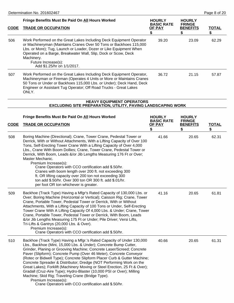
Fringe Benefits Must Be Paid On All Hours Worked
CODE TRADE OR OCCUPATION OF PAY BENEFITS TOTAL
Work Performed on the Great Lakes Including Deck Equipment Operatoror Machineryman (Maintains Cranes Over 50 Tons or Backhoes 115,000Lbs. or More); Tug, Launch or Loader, Dozer or Like Equipment WhenOperated on a Barge, Breakwater Wall, Slip, Dock or Scow, DeckMachinery.
Future Increase(s):Add $1.25/hr on 1/1/2017.
Work Performed on the Great Lakes Including Deck Equipment Operator,Machineryman or Fireman (Operates 4 Units or More or Maintains Cranes50 Tons or Under or Backhoes 115,000 Lbs. or Under); Deck Hand, DeckEngineer or Assistant Tug Operator; Off Road Trucks - Great LakesONLY.
Fringe Benefits Must Be Paid On All Hours Worked
CODE TRADE OR OCCUPATION OF PAY BENEFITS TOTAL
Boring Machine (Directional); Crane, Tower Crane, Pedestal Tower orDerrick, With or Without Attachments, With a Lifting Capacity of Over 100Tons, Self-Erecting Tower Crane With a Lifting Capacity of Over 4,000Lbs., Crane With Boom Dollies; Crane, Tower Crane, Pedestal Tower orDerrick, With Boom, Leads &/or Jib Lengths Measuring 176 Ft or Over;Master Mechanic.
Premium Increase(s):Crane Operators with CCO certification add $.50/hr.Cranes with boom length over 200 ft. not exceeding 300ft. OR lifting capacity over 200 ton not exceeding 300ton add $.50/hr. Over 300 ton OR 300 ft. add $.01/hr.per foot OR ton whichever is greater.
Backhoe (Track Type) Having a Mfgr's Rated Capacity of 130,000 Lbs. orOver; Boring Machine (Horizontal or Vertical); Caisson Rig; Crane, TowerCrane, Portable Tower, Pedestal Tower or Derrick, With or WithoutAttachments, With a Lifting Capacity of 100 Tons or Under, Self-ErectingTower Crane With A Lifting Capacity Of 4,000 Lbs. & Under; Crane, TowerCrane, Portable Tower, Pedestal Tower or Derrick, With Boom, Leads&/or Jib Lengths Measuring 175 Ft or Under; Pile Driver; Versi Lifts,Tri-Lifts & Gantrys (20,000 Lbs. & Over).
Premium Increase(s):Crane Operators with CCO certification add $.50/hr.
Backhoe (Track Type) Having a Mfgr.'s Rated Capacity of Under 130,000Lbs., Backhoe (Mini, 15,000 Lbs. & Under); Concrete Bump Cutter,Grinder, Planing or Grooving Machine; Concrete Laser/Screed; ConcretePaver (Slipform); Concrete Pump (Over 46 Meter), Concrete Conveyor(Rotec or Bidwell Type); Concrete Slipform Placer Curb & Gutter Machine;Concrete Spreader & Distributor; Dredge (NOT Performing Work on theGreat Lakes); Forklift (Machinery Moving or Steel Erection, 25 Ft & Over);Gradall (Cruz-Aire Type); Hydro-Blaster (10,000 PSI or Over); MillingMachine; Skid Rig; Traveling Crane (Bridge Type).
Premium Increase(s):Crane Operators with CCO certification add $.50/hr.
Determination No. 201602467
HOURLY HOURLYBASIC RATE FRINGE
$ $ $
506 39.20 23.09 62.29
507 36.72 21.15 57.87
HEAVY EQUIPMENT OPERATORS EXCLUDING SITE PREPARATION, UTILITY, PAVING LANDSCAPING WORK
HOURLY HOURLYBASIC RATE FRINGE
$ $ $
508 41.66 20.65 62.31
509 41.16 20.65 61.81
510 40.66 20.65 61.31
Page 8 of 20

Fringe Benefits Must Be Paid On All Hours Worked
CODE TRADE OR OCCUPATION OF PAY BENEFITS TOTAL
Air, Track, Rotary or Percussion Drilling Machine &/or Hammers, Blaster;Bulldozer or Endloader (Over 40 hp); Compactor (Self-Propelled 85 FtTotal Drum Width & Over, or Tractor Mounted, Towed & Light Equipment);Concrete Pump (46 Meter & Under), Concrete Conveyor (Rotec or BidwellType); Crane (Carry Deck, Mini) or Truck Mounted Hydraulic Crane (10Tons or Under); Environmental Burner; Gantrys (Under 20,000 Lbs.);Grader or Motor Patrol; High Pressure Utility Locating Machine(Daylighting Machine); Manhoist; Material or Stack Hoist; Mechanic orWelder; Railroad Track Rail Leveling Machine, Tie Placer, Extractor,Tamper, Stone Leveler or Rehabilitation Equipment; Roller (Over 5 Ton);Scraper (Self Propelled or Tractor Drawn) 5 cu yd or More Capacity;Screed (Milling Machine); Sideboom; Straddle Carrier or Travel Lift; Tiningor Curing Machine; Tractor (Scraper, Dozer, Pusher, Loader); Tractor orTruck Mounted Hydraulic Backhoe; Tractor or Truck Mounted HydraulicCrane (10 Tons or Under); Trencher (Wheel Type or Chain Type HavingOver 8-Inch Bucket).
Backfiller; Broom or Sweeper; Bulldozer or Endloader (Under 40 hp);Compactor (Self-Propelled 84 Ft Total Drum Width & Under, or TractorMounted, Towed & Light Equipment); Concrete Batch Plant, BatchHopper; Concrete Breaker (Large, Auto, Vibratory/Sonic, Manual orRemote); Concrete Conveyor System; Concrete Finishing Machine (RoadType); Fireman (Pile Driver & Derrick NOT Performing Work on the GreatLakes); Grout Pump; Hoist (Tugger, Automatic); Industrial Locomotives;Jeep Digger; Lift Slab Machine; Mulcher; Roller (Rubber Tire, 5 Ton orUnder); Screw or Gypsum Pumps; Stabilizing or Concrete Mixer(Self-Propelled or 14S or Over); Stump Chipper; Trencher (Wheel Type orChain Type Having 8-Inch Bucket & Under); Winches & A-Frames.
Air Compressor (&/or 400 CFM or Over); Air, Electric or Hydraulic JackingSystem; Augers (Vertical & Horizontal); Boatmen (NOT Performing Workon the Great Lakes); Boiler (Temporary Heat); Crusher, Screening orWash Plant; Elevator; Farm or Industrial Type Tractor; Fireman (AsphaltPlant NOT Performing Work on the Great Lakes); Forklift; Generator (&/or150 KW or Over); Greaser; Heaters (Mechanical); Loading Machine(Conveyor); Oiler; Post Hole Digger or Driver; Prestress Machine; Pump(3 Inch or Over) or Well Points; Refrigeration Plant or Freeze Machine;Robotic Tool Carrier (With or Without Attachments); Rock, Stone Breaker;Skid Steer Loader (With or Without Attachments); Vibratory Hammer orExtractor, Power Pack.
Gas or Utility Pipeline, Except Sewer & Water (Primary Equipment).Future Increase(s):
Add $1/hr on 5/30/2016.
Gas or Utility Pipeline, Except Sewer & Water (Secondary Equipment).
Fiber Optic Cable Equipment
Determination No. 201602467
HOURLY HOURLYBASIC RATE FRINGE
$ $ $
511 39.97 20.65 60.62
512 38.09 20.65 58.74
513 32.94 20.65 53.59
514 37.04 22.44 59.48
515 34.76 20.30 55.06
516 21.00 0.00 21.00
Page 9 of 20
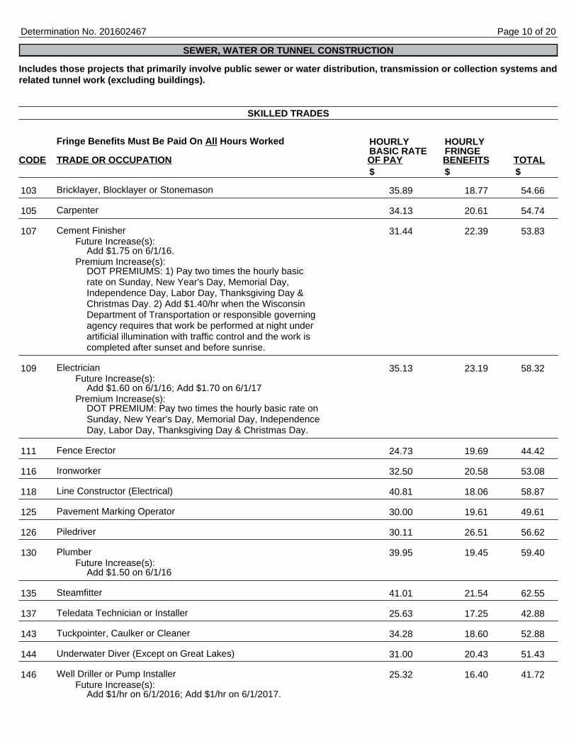
Includes those projects that primarily involve public sewer or water distribution, transmission or collection systems andrelated tunnel work (excluding buildings).
Fringe Benefits Must Be Paid On All Hours Worked
CODE TRADE OR OCCUPATION OF PAY BENEFITS TOTAL
Bricklayer, Blocklayer or Stonemason
Carpenter
Cement FinisherFuture Increase(s):
Add $1.75 on 6/1/16.Premium Increase(s):
DOT PREMIUMS: 1) Pay two times the hourly basicrate on Sunday, New Year's Day, Memorial Day,Independence Day, Labor Day, Thanksgiving Day &Christmas Day. 2) Add $1.40/hr when the WisconsinDepartment of Transportation or responsible governingagency requires that work be performed at night underartificial illumination with traffic control and the work iscompleted after sunset and before sunrise.
ElectricianFuture Increase(s):
Add $1.60 on 6/1/16; Add $1.70 on 6/1/17Premium Increase(s):
DOT PREMIUM: Pay two times the hourly basic rate onSunday, New Year’s Day, Memorial Day, IndependenceDay, Labor Day, Thanksgiving Day & Christmas Day.
Fence Erector
Ironworker
Line Constructor (Electrical)
Pavement Marking Operator
Piledriver
PlumberFuture Increase(s):
Add $1.50 on 6/1/16
Steamfitter
Teledata Technician or Installer
Tuckpointer, Caulker or Cleaner
Underwater Diver (Except on Great Lakes)
Well Driller or Pump InstallerFuture Increase(s):
Add $1/hr on 6/1/2016; Add $1/hr on 6/1/2017.
Determination No. 201602467
SEWER, WATER OR TUNNEL CONSTRUCTION
SKILLED TRADES
HOURLY HOURLYBASIC RATE FRINGE
$ $ $
103 35.89 18.77 54.66
105 34.13 20.61 54.74
107 31.44 22.39 53.83
109 35.13 23.19 58.32
111 24.73 19.69 44.42
116 32.50 20.58 53.08
118 40.81 18.06 58.87
125 30.00 19.61 49.61
126 30.11 26.51 56.62
130 39.95 19.45 59.40
135 41.01 21.54 62.55
137 25.63 17.25 42.88
143 34.28 18.60 52.88
144 31.00 20.43 51.43
146 25.32 16.40 41.72
Page 10 of 20
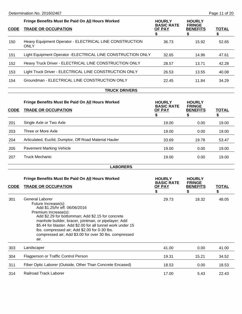
Fringe Benefits Must Be Paid On All Hours Worked
CODE TRADE OR OCCUPATION OF PAY BENEFITS TOTAL
Heavy Equipment Operator - ELECTRICAL LINE CONSTRUCTIONONLY
Light Equipment Operator -ELECTRICAL LINE CONSTRUCTION ONLY
Heavy Truck Driver - ELECTRICAL LINE CONSTRUCTION ONLY
Light Truck Driver - ELECTRICAL LINE CONSTRUCTION ONLY
Groundman - ELECTRICAL LINE CONSTRUCTION ONLY
Fringe Benefits Must Be Paid On All Hours Worked
CODE TRADE OR OCCUPATION OF PAY BENEFITS TOTAL
Single Axle or Two Axle
Three or More Axle
Articulated, Euclid, Dumptor, Off Road Material Hauler
Pavement Marking Vehicle
Truck Mechanic
Fringe Benefits Must Be Paid On All Hours Worked
CODE TRADE OR OCCUPATION OF PAY BENEFITS TOTAL
General LaborerFuture Increase(s):
Add $1.25/hr eff. 06/06/2016Premium Increase(s):
Add $2.29 for bottomman; Add $2.15 for concretemanhole builder, bracer, jointman, or pipelayer; Add$5.44 for blaster. Add $2.00 for all tunnel work under 15lbs. compressed air; Add $2.00 for 0-30 lbs.compressed air; Add $3.00 for over 30 lbs. compressedair.
Landscaper
Flagperson or Traffic Control Person
Fiber Optic Laborer (Outside, Other Than Concrete Encased)
Railroad Track Laborer
Determination No. 201602467
HOURLY HOURLYBASIC RATE FRINGE
$ $ $
150 36.73 15.92 52.65
151 32.65 14.96 47.61
152 28.57 13.71 42.28
153 26.53 13.55 40.08
154 22.45 11.84 34.29
TRUCK DRIVERS
HOURLY HOURLYBASIC RATE FRINGE
$ $ $
201 19.00 0.00 19.00
203 19.00 0.00 19.00
204 33.69 19.78 53.47
205 19.00 0.00 19.00
207 19.00 0.00 19.00
LABORERS
HOURLY HOURLYBASIC RATE FRINGE
$ $ $
301 29.73 18.32 48.05
303 41.00 0.00 41.00
304 19.31 15.21 34.52
311 18.53 0.00 18.53
314 17.00 5.43 22.43
Page 11 of 20
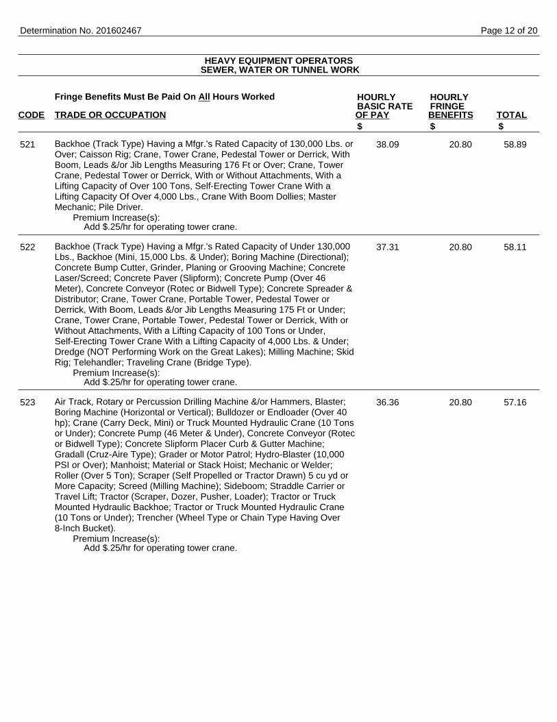
Fringe Benefits Must Be Paid On All Hours Worked
CODE TRADE OR OCCUPATION OF PAY BENEFITS TOTAL
Backhoe (Track Type) Having a Mfgr.'s Rated Capacity of 130,000 Lbs. orOver; Caisson Rig; Crane, Tower Crane, Pedestal Tower or Derrick, WithBoom, Leads &/or Jib Lengths Measuring 176 Ft or Over; Crane, TowerCrane, Pedestal Tower or Derrick, With or Without Attachments, With aLifting Capacity of Over 100 Tons, Self-Erecting Tower Crane With aLifting Capacity Of Over 4,000 Lbs., Crane With Boom Dollies; MasterMechanic; Pile Driver.
Premium Increase(s):Add $.25/hr for operating tower crane.
Backhoe (Track Type) Having a Mfgr.'s Rated Capacity of Under 130,000Lbs., Backhoe (Mini, 15,000 Lbs. & Under); Boring Machine (Directional);Concrete Bump Cutter, Grinder, Planing or Grooving Machine; ConcreteLaser/Screed; Concrete Paver (Slipform); Concrete Pump (Over 46Meter), Concrete Conveyor (Rotec or Bidwell Type); Concrete Spreader &Distributor; Crane, Tower Crane, Portable Tower, Pedestal Tower orDerrick, With Boom, Leads &/or Jib Lengths Measuring 175 Ft or Under;Crane, Tower Crane, Portable Tower, Pedestal Tower or Derrick, With orWithout Attachments, With a Lifting Capacity of 100 Tons or Under,Self-Erecting Tower Crane With a Lifting Capacity of 4,000 Lbs. & Under;Dredge (NOT Performing Work on the Great Lakes); Milling Machine; SkidRig; Telehandler; Traveling Crane (Bridge Type).
Premium Increase(s):Add $.25/hr for operating tower crane.
Air Track, Rotary or Percussion Drilling Machine &/or Hammers, Blaster;Boring Machine (Horizontal or Vertical); Bulldozer or Endloader (Over 40hp); Crane (Carry Deck, Mini) or Truck Mounted Hydraulic Crane (10 Tonsor Under); Concrete Pump (46 Meter & Under), Concrete Conveyor (Rotecor Bidwell Type); Concrete Slipform Placer Curb & Gutter Machine;Gradall (Cruz-Aire Type); Grader or Motor Patrol; Hydro-Blaster (10,000PSI or Over); Manhoist; Material or Stack Hoist; Mechanic or Welder;Roller (Over 5 Ton); Scraper (Self Propelled or Tractor Drawn) 5 cu yd orMore Capacity; Screed (Milling Machine); Sideboom; Straddle Carrier orTravel Lift; Tractor (Scraper, Dozer, Pusher, Loader); Tractor or TruckMounted Hydraulic Backhoe; Tractor or Truck Mounted Hydraulic Crane(10 Tons or Under); Trencher (Wheel Type or Chain Type Having Over8-Inch Bucket).
Premium Increase(s):Add $.25/hr for operating tower crane.
Determination No. 201602467
HEAVY EQUIPMENT OPERATORS SEWER, WATER OR TUNNEL WORK
HOURLY HOURLYBASIC RATE FRINGE
$ $ $
521 38.09 20.80 58.89
522 37.31 20.80 58.11
523 36.36 20.80 57.16
Page 12 of 20
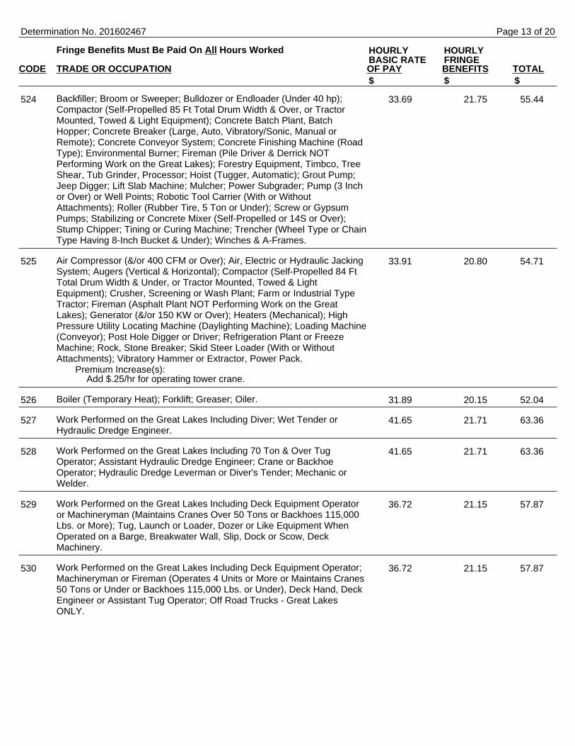
Fringe Benefits Must Be Paid On All Hours Worked
CODE TRADE OR OCCUPATION OF PAY BENEFITS TOTAL
Backfiller; Broom or Sweeper; Bulldozer or Endloader (Under 40 hp);Compactor (Self-Propelled 85 Ft Total Drum Width & Over, or TractorMounted, Towed & Light Equipment); Concrete Batch Plant, BatchHopper; Concrete Breaker (Large, Auto, Vibratory/Sonic, Manual orRemote); Concrete Conveyor System; Concrete Finishing Machine (RoadType); Environmental Burner; Fireman (Pile Driver & Derrick NOTPerforming Work on the Great Lakes); Forestry Equipment, Timbco, TreeShear, Tub Grinder, Processor; Hoist (Tugger, Automatic); Grout Pump;Jeep Digger; Lift Slab Machine; Mulcher; Power Subgrader; Pump (3 Inchor Over) or Well Points; Robotic Tool Carrier (With or WithoutAttachments); Roller (Rubber Tire, 5 Ton or Under); Screw or GypsumPumps; Stabilizing or Concrete Mixer (Self-Propelled or 14S or Over);Stump Chipper; Tining or Curing Machine; Trencher (Wheel Type or ChainType Having 8-Inch Bucket & Under); Winches & A-Frames.
Air Compressor (&/or 400 CFM or Over); Air, Electric or Hydraulic JackingSystem; Augers (Vertical & Horizontal); Compactor (Self-Propelled 84 FtTotal Drum Width & Under, or Tractor Mounted, Towed & LightEquipment); Crusher, Screening or Wash Plant; Farm or Industrial TypeTractor; Fireman (Asphalt Plant NOT Performing Work on the GreatLakes); Generator (&/or 150 KW or Over); Heaters (Mechanical); HighPressure Utility Locating Machine (Daylighting Machine); Loading Machine(Conveyor); Post Hole Digger or Driver; Refrigeration Plant or FreezeMachine; Rock, Stone Breaker; Skid Steer Loader (With or WithoutAttachments); Vibratory Hammer or Extractor, Power Pack.
Premium Increase(s):Add $.25/hr for operating tower crane.
Boiler (Temporary Heat); Forklift; Greaser; Oiler.
Work Performed on the Great Lakes Including Diver; Wet Tender orHydraulic Dredge Engineer.
Work Performed on the Great Lakes Including 70 Ton & Over TugOperator; Assistant Hydraulic Dredge Engineer; Crane or BackhoeOperator; Hydraulic Dredge Leverman or Diver's Tender; Mechanic orWelder.
Work Performed on the Great Lakes Including Deck Equipment Operatoror Machineryman (Maintains Cranes Over 50 Tons or Backhoes 115,000Lbs. or More); Tug, Launch or Loader, Dozer or Like Equipment WhenOperated on a Barge, Breakwater Wall, Slip, Dock or Scow, DeckMachinery.
Work Performed on the Great Lakes Including Deck Equipment Operator;Machineryman or Fireman (Operates 4 Units or More or Maintains Cranes50 Tons or Under or Backhoes 115,000 Lbs. or Under), Deck Hand, DeckEngineer or Assistant Tug Operator; Off Road Trucks - Great LakesONLY.
Determination No. 201602467
HOURLY HOURLYBASIC RATE FRINGE
$ $ $
524 33.69 21.75 55.44
525 33.91 20.80 54.71
526 31.89 20.15 52.04
527 41.65 21.71 63.36
528 41.65 21.71 63.36
529 36.72 21.15 57.87
530 36.72 21.15 57.87
Page 13 of 20
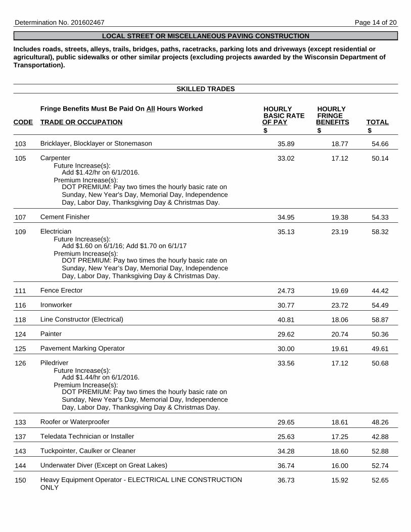
Includes roads, streets, alleys, trails, bridges, paths, racetracks, parking lots and driveways (except residential oragricultural), public sidewalks or other similar projects (excluding projects awarded by the Wisconsin Department ofTransportation).
Fringe Benefits Must Be Paid On All Hours Worked
CODE TRADE OR OCCUPATION OF PAY BENEFITS TOTAL
Bricklayer, Blocklayer or Stonemason
CarpenterFuture Increase(s):
Add $1.42/hr on 6/1/2016.Premium Increase(s):
DOT PREMIUM: Pay two times the hourly basic rate onSunday, New Year's Day, Memorial Day, IndependenceDay, Labor Day, Thanksgiving Day & Christmas Day.
Cement Finisher
ElectricianFuture Increase(s):
Add $1.60 on 6/1/16; Add $1.70 on 6/1/17Premium Increase(s):
DOT PREMIUM: Pay two times the hourly basic rate onSunday, New Year’s Day, Memorial Day, IndependenceDay, Labor Day, Thanksgiving Day & Christmas Day.
Fence Erector
Ironworker
Line Constructor (Electrical)
Painter
Pavement Marking Operator
PiledriverFuture Increase(s):
Add $1.44/hr on 6/1/2016.Premium Increase(s):
DOT PREMIUM: Pay two times the hourly basic rate onSunday, New Year's Day, Memorial Day, IndependenceDay, Labor Day, Thanksgiving Day & Christmas Day.
Roofer or Waterproofer
Teledata Technician or Installer
Tuckpointer, Caulker or Cleaner
Underwater Diver (Except on Great Lakes)
Heavy Equipment Operator - ELECTRICAL LINE CONSTRUCTIONONLY
Determination No. 201602467
LOCAL STREET OR MISCELLANEOUS PAVING CONSTRUCTION
SKILLED TRADES
HOURLY HOURLYBASIC RATE FRINGE
$ $ $
103 35.89 18.77 54.66
105 33.02 17.12 50.14
107 34.95 19.38 54.33
109 35.13 23.19 58.32
111 24.73 19.69 44.42
116 30.77 23.72 54.49
118 40.81 18.06 58.87
124 29.62 20.74 50.36
125 30.00 19.61 49.61
126 33.56 17.12 50.68
133 29.65 18.61 48.26
137 25.63 17.25 42.88
143 34.28 18.60 52.88
144 36.74 16.00 52.74
150 36.73 15.92 52.65
Page 14 of 20

Fringe Benefits Must Be Paid On All Hours Worked
CODE TRADE OR OCCUPATION OF PAY BENEFITS TOTAL
Light Equipment Operator -ELECTRICAL LINE CONSTRUCTION ONLY
Heavy Truck Driver - ELECTRICAL LINE CONSTRUCTION ONLY
Light Truck Driver - ELECTRICAL LINE CONSTRUCTION ONLY
Groundman - ELECTRICAL LINE CONSTRUCTION ONLY
Fringe Benefits Must Be Paid On All Hours Worked
CODE TRADE OR OCCUPATION OF PAY BENEFITS TOTAL
Single Axle or Two Axle
Three or More Axle
Articulated, Euclid, Dumptor, Off Road Material HaulerFuture Increase(s):
Add $1.60/hr on 6/3/2016.
Pavement Marking Vehicle
Shadow or Pilot Vehicle
Truck Mechanic
Fringe Benefits Must Be Paid On All Hours Worked
CODE TRADE OR OCCUPATION OF PAY BENEFITS TOTAL
General Laborer
LandscaperFuture Increase(s):
Add $1.00/hr eff. 06/01/2016; Add $1.00/hr eff.06/01/2017
Premium Increase(s):DOT PREMIUMS: 1) Pay two times the hourly basicrate on Sunday, New Year's Day, Memorial Day,Independence Day, Labor Day, Thanksgiving Day &Christmas Day. 2) Add $1.25/hr for work on projectsinvolving temporary traffic control setup, for lane andshoulder closures, when work under artificial illuminationconditions is necessary as required by the projectprovisions (including prep time prior to and/or cleanupafter such time period).
Flagperson or Traffic Control Person
Fiber Optic Laborer (Outside, Other Than Concrete Encased)
Determination No. 201602467
HOURLY HOURLYBASIC RATE FRINGE
$ $ $
151 32.65 14.96 47.61
152 28.57 13.71 42.28
153 26.53 13.55 40.08
154 22.45 11.84 34.29
TRUCK DRIVERS
HOURLY HOURLYBASIC RATE FRINGE
$ $ $
201 19.00 0.00 19.00
203 19.00 0.00 19.00
204 34.69 20.38 55.07
205 19.00 0.00 19.00
206 19.00 0.00 19.00
207 19.00 0.00 19.00
LABORERS
HOURLY HOURLYBASIC RATE FRINGE
$ $ $
301 29.01 17.39 46.40
303 27.51 20.63 48.14
304 19.31 15.21 34.52
311 18.53 0.00 18.53
Page 15 of 20
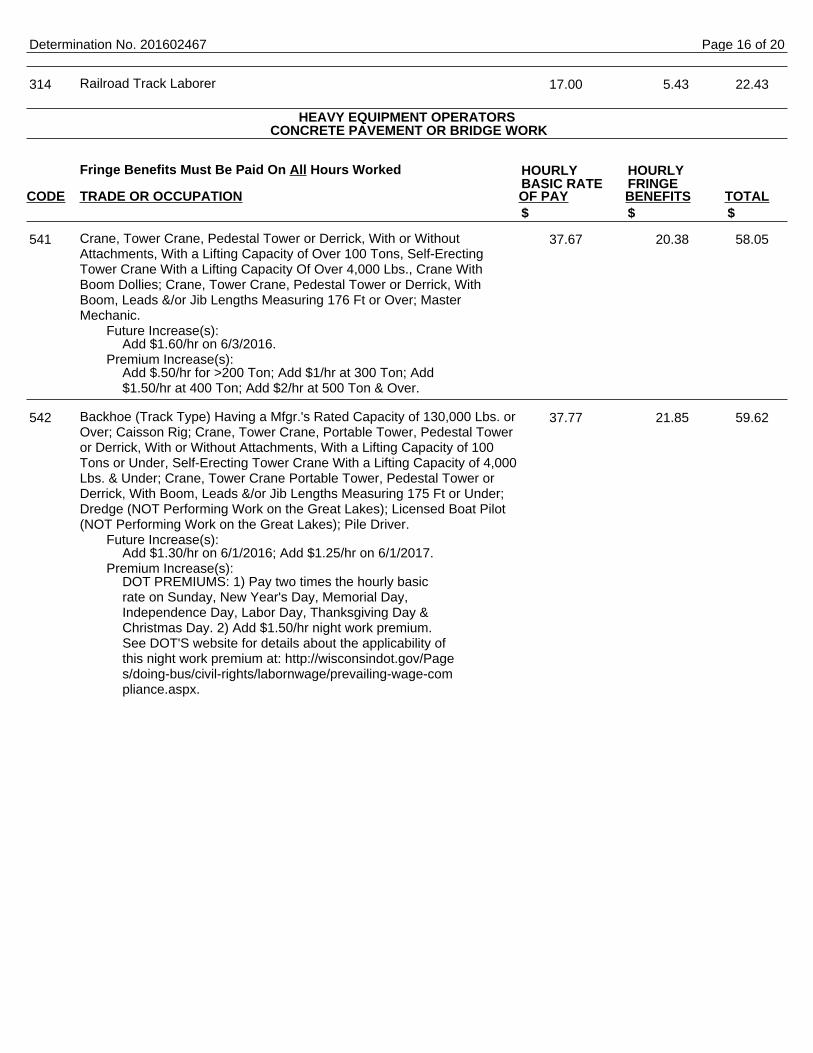
Railroad Track Laborer
Fringe Benefits Must Be Paid On All Hours Worked
CODE TRADE OR OCCUPATION OF PAY BENEFITS TOTAL
Crane, Tower Crane, Pedestal Tower or Derrick, With or WithoutAttachments, With a Lifting Capacity of Over 100 Tons, Self-ErectingTower Crane With a Lifting Capacity Of Over 4,000 Lbs., Crane WithBoom Dollies; Crane, Tower Crane, Pedestal Tower or Derrick, WithBoom, Leads &/or Jib Lengths Measuring 176 Ft or Over; MasterMechanic.
Future Increase(s):Add $1.60/hr on 6/3/2016.
Premium Increase(s):Add $.50/hr for >200 Ton; Add $1/hr at 300 Ton; Add$1.50/hr at 400 Ton; Add $2/hr at 500 Ton & Over.
Backhoe (Track Type) Having a Mfgr.'s Rated Capacity of 130,000 Lbs. orOver; Caisson Rig; Crane, Tower Crane, Portable Tower, Pedestal Toweror Derrick, With or Without Attachments, With a Lifting Capacity of 100Tons or Under, Self-Erecting Tower Crane With a Lifting Capacity of 4,000Lbs. & Under; Crane, Tower Crane Portable Tower, Pedestal Tower orDerrick, With Boom, Leads &/or Jib Lengths Measuring 175 Ft or Under;Dredge (NOT Performing Work on the Great Lakes); Licensed Boat Pilot(NOT Performing Work on the Great Lakes); Pile Driver.
Future Increase(s):Add $1.30/hr on 6/1/2016; Add $1.25/hr on 6/1/2017.
Premium Increase(s):DOT PREMIUMS: 1) Pay two times the hourly basicrate on Sunday, New Year's Day, Memorial Day,Independence Day, Labor Day, Thanksgiving Day &Christmas Day. 2) Add $1.50/hr night work premium.See DOT'S website for details about the applicability ofthis night work premium at: http://wisconsindot.gov/Pages/doing-bus/civil-rights/labornwage/prevailing-wage-compliance.aspx.
Determination No. 201602467
314 17.00 5.43 22.43
HEAVY EQUIPMENT OPERATORS CONCRETE PAVEMENT OR BRIDGE WORK
HOURLY HOURLYBASIC RATE FRINGE
$ $ $
541 37.67 20.38 58.05
542 37.77 21.85 59.62
Page 16 of 20

Fringe Benefits Must Be Paid On All Hours Worked
CODE TRADE OR OCCUPATION OF PAY BENEFITS TOTAL
Air Track, Rotary or Percussion Drilling Machine &/or Hammers, Blaster;Automatic Subgrader (Concrete); Backhoe (Track Type) Having a Mfgr.'sRated Capacity of Under 130,000 Lbs., Backhoe (Mini, 15,000 Lbs. &Under); Boring Machine (Directional, Horizontal or Vertical); Bridge(Bidwell) Paver; Bulldozer or Endloader; Concrete Batch Plant, BatchHopper; Concrete Breaker (Large, Auto, Vibratory/Sonic, Manual orRemote); Concrete Bump Cutter, Grinder, Planing or Grooving Machine;Concrete Conveyor System; Concrete Laser/Screed; Concrete Paver(Slipform); Concrete Pump, Concrete Conveyor (Rotec or Bidwell Type);Concrete Slipform Placer Curb & Gutter Machine; Concrete Spreader &Distributor; Crane (Carry Deck, Mini) or Truck Mounted Hydraulic Crane(10 Tons or Under); Crane With a Lifting Capacity of 25 Tons or Under;Forestry Equipment, Timbco, Tree Shear, Tub Grinder, Processor; Gradall(Cruz-Aire Type); Grader or Motor Patrol; Grout Pump; Hydro-Blaster(10,000 PSI or Over); Loading Machine (Conveyor); Manhoist; Material orStack Hoist; Mechanic or Welder; Milling Machine; Post Hole Digger orDriver; Scraper (Self Propelled or Tractor Drawn) 5 cu yds or MoreCapacity; Shoulder Widener; Sideboom; Skid Rig; Stabilizing or ConcreteMixer (Self-Propelled or 14S or Over); Straddle Carrier or Travel Lift;Tractor (Scraper, Dozer, Pusher, Loader); Tractor or Truck MountedHydraulic Backhoe; Trencher (Wheel Type or Chain Type); Tube Finisher;Tugger (NOT Performing Work on the Great Lakes); Winches &A-Frames.
Future Increase(s):Add $1.30/hr on 6/1/2016; Add $1.25/hr on 6/1/2017.
Premium Increase(s):DOT PREMIUMS: 1) Pay two times the hourly basicrate on Sunday, New Year's Day, Memorial Day,Independence Day, Labor Day, Thanksgiving Day &Christmas Day. 2) Add $1.50/hr night work premium.See DOT'S website for details about the applicability ofthis night work premium at: http://wisconsindot.gov/Pages/doing-bus/civil-rights/labornwage/prevailing-wage-compliance.aspx.
Backfiller; Belting, Burlap, Texturing Machine; Broom or Sweeper;Compactor (Self-Propelled or Tractor Mounted, Towed & LightEquipment); Concrete Finishing Machine (Road Type); EnvironmentalBurner; Farm or Industrial Type Tractor; Fireman (Pile Driver & DerrickNOT Performing Work on the Great Lakes); Forklift; Greaser; Jeep Digger;Joint Sawer (Multiple Blade); Launch (NOT Performing Work on the GreatLakes); Lift Slab Machine; Mechanical Float; Mulcher; Power Subgrader;Robotic Tool Carrier (WIth or Without Attachments); Self Propelled ChipSpreader; Shouldering Machine; Skid Steer Loader (With or WithoutAttachments); Telehandler; Tining or Curing Machine.
Future Increase(s):Add $1.30/hr on 6/1/2016; Add $1.25/hr on 6/1/2017.
Premium Increase(s):DOT PREMIUMS: 1) Pay two times the hourly basicrate on Sunday, New Year's Day, Memorial Day,Independence Day, Labor Day, Thanksgiving Day &Christmas Day. 2) Add $1.50/hr night work premium.See DOT'S website for details about the applicability ofthis night work premium at: http://wisconsindot.gov/Pages/doing-bus/civil-rights/labornwage/prevailing-wage-compliance.aspx.
Determination No. 201602467
HOURLY HOURLYBASIC RATE FRINGE
$ $ $
543 37.27 21.85 59.12
544 37.27 21.85 59.12
Page 17 of 20
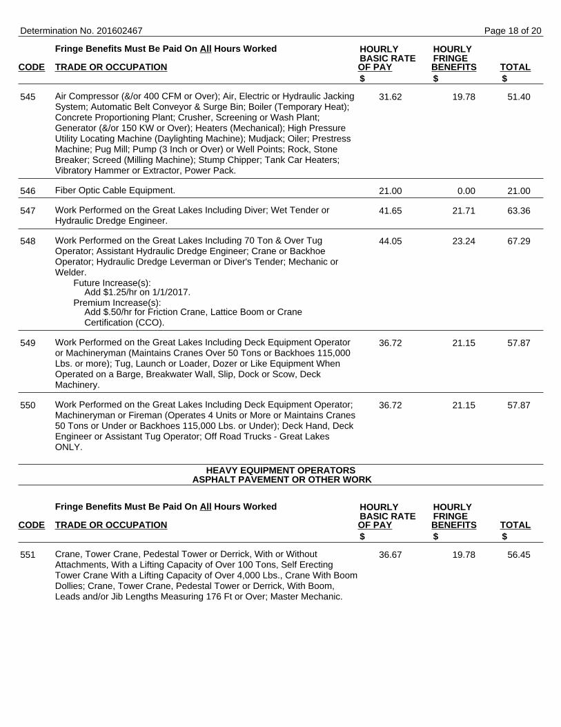
Fringe Benefits Must Be Paid On All Hours Worked
CODE TRADE OR OCCUPATION OF PAY BENEFITS TOTAL
Air Compressor (&/or 400 CFM or Over); Air, Electric or Hydraulic JackingSystem; Automatic Belt Conveyor & Surge Bin; Boiler (Temporary Heat);Concrete Proportioning Plant; Crusher, Screening or Wash Plant;Generator (&/or 150 KW or Over); Heaters (Mechanical); High PressureUtility Locating Machine (Daylighting Machine); Mudjack; Oiler; PrestressMachine; Pug Mill; Pump (3 Inch or Over) or Well Points; Rock, StoneBreaker; Screed (Milling Machine); Stump Chipper; Tank Car Heaters;Vibratory Hammer or Extractor, Power Pack.
Fiber Optic Cable Equipment.
Work Performed on the Great Lakes Including Diver; Wet Tender orHydraulic Dredge Engineer.
Work Performed on the Great Lakes Including 70 Ton & Over TugOperator; Assistant Hydraulic Dredge Engineer; Crane or BackhoeOperator; Hydraulic Dredge Leverman or Diver's Tender; Mechanic orWelder.
Future Increase(s):Add $1.25/hr on 1/1/2017.
Premium Increase(s):Add $.50/hr for Friction Crane, Lattice Boom or CraneCertification (CCO).
Work Performed on the Great Lakes Including Deck Equipment Operatoror Machineryman (Maintains Cranes Over 50 Tons or Backhoes 115,000Lbs. or more); Tug, Launch or Loader, Dozer or Like Equipment WhenOperated on a Barge, Breakwater Wall, Slip, Dock or Scow, DeckMachinery.
Work Performed on the Great Lakes Including Deck Equipment Operator;Machineryman or Fireman (Operates 4 Units or More or Maintains Cranes50 Tons or Under or Backhoes 115,000 Lbs. or Under); Deck Hand, DeckEngineer or Assistant Tug Operator; Off Road Trucks - Great LakesONLY.
Fringe Benefits Must Be Paid On All Hours Worked
CODE TRADE OR OCCUPATION OF PAY BENEFITS TOTAL
Crane, Tower Crane, Pedestal Tower or Derrick, With or WithoutAttachments, With a Lifting Capacity of Over 100 Tons, Self ErectingTower Crane With a Lifting Capacity of Over 4,000 Lbs., Crane With BoomDollies; Crane, Tower Crane, Pedestal Tower or Derrick, With Boom,Leads and/or Jib Lengths Measuring 176 Ft or Over; Master Mechanic.
Determination No. 201602467
HOURLY HOURLYBASIC RATE FRINGE
$ $ $
545 31.62 19.78 51.40
546 21.00 0.00 21.00
547 41.65 21.71 63.36
548 44.05 23.24 67.29
549 36.72 21.15 57.87
550 36.72 21.15 57.87
HEAVY EQUIPMENT OPERATORSASPHALT PAVEMENT OR OTHER WORK
HOURLY HOURLYBASIC RATE FRINGE
$ $ $
551 36.67 19.78 56.45
Page 18 of 20
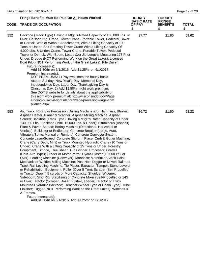
Fringe Benefits Must Be Paid On All Hours Worked
CODE TRADE OR OCCUPATION OF PAY BENEFITS TOTAL
Backhoe (Track Type) Having a Mfgr.'s Rated Capacity of 130,000 Lbs. orOver; Caisson Rig; Crane, Tower Crane, Portable Tower, Pedestal Toweror Derrick, With or Without Attachments, With a Lifting Capacity of 100Tons or Under, Self-Erecting Tower Crane With a Lifting Capacity Of4,000 Lbs. & Under; Crane, Tower Crane, Portable Tower, PedestalTower or Derrick, With Boom, Leads &/or Jib Lengths Measuring 175 Ft orUnder; Dredge (NOT Performing Work on the Great Lakes); LicensedBoat Pilot (NOT Performing Work on the Great Lakes); Pile Driver.
Future Increase(s):Add $1.30/hr on 6/1/2016; Add $1.25/hr on 6/1/2017.
Premium Increase(s):DOT PREMIUMS: 1) Pay two times the hourly basicrate on Sunday, New Year's Day, Memorial Day,Independence Day, Labor Day, Thanksgiving Day &Christmas Day. 2) Add $1.50/hr night work premium.See DOT'S website for details about the applicability ofthis night work premium at: http://wisconsindot.gov/Pages/doing-bus/civil-rights/labornwage/prevailing-wage-compliance.aspx.
Air, Track, Rotary or Percussion Drilling Machine &/or Hammers, Blaster;Asphalt Heater, Planer & Scarifier; Asphalt Milling Machine; AsphaltScreed; Backhoe (Track Type) Having a Mfgr.'s Rated Capacity of Under130,000 Lbs., Backhoe (Mini, 15,000 Lbs. & Under); Bituminous (Asphalt)Plant & Paver, Screed; Boring Machine (Directional, Horizontal orVertical); Bulldozer or Endloader; Concrete Breaker (Large, Auto,Vibratory/Sonic, Manual or Remote); Concrete Conveyor System;Concrete Laser/Screed; Concrete Slipform Placer Curb & Gutter Machine;Crane (Carry Deck, Mini) or Truck Mounted Hydraulic Crane (10 Tons orUnder); Crane With a Lifting Capacity of 25 Tons or Under; ForestryEquipment, Timbco, Tree Shear, Tub Grinder, Processor; Gradall(Cruz-Aire Type); Grader or Motor Patrol; Hydro-Blaster (10,000 PSI orOver); Loading Machine (Conveyor); Manhoist; Material or Stack Hoist;Mechanic or Welder; Milling Machine; Post Hole Digger or Driver; RailroadTrack Rail Leveling Machine, Tie Placer, Extractor, Tamper, Stone Leveleror Rehabilitation Equipment; Roller (Over 5 Ton); Scraper (Self Propelledor Tractor Drawn) 5 cu yds or More Capacity; Shoulder Widener;Sideboom; Skid Rig; Stabilizing or Concrete Mixer (Self-Propelled or 14Sor Over); Tractor (Scraper, Dozer, Pusher, Loader); Tractor or TruckMounted Hydraulic Backhoe; Trencher (Wheel Type or Chain Type); TubeFinisher; Tugger (NOT Performing Work on the Great Lakes); Winches &A-Frames.
Future Increase(s):Add $1.30/hr on 6/1/2016; Add $1.25/hr on 6/1/2017.
Determination No. 201602467
HOURLY HOURLYBASIC RATE FRINGE
$ $ $
552 37.77 21.85 59.62
553 36.72 21.50 58.22
Page 19 of 20

Fringe Benefits Must Be Paid On All Hours Worked
CODE TRADE OR OCCUPATION OF PAY BENEFITS TOTAL
Backfiller; Broom or Sweeper; Compactor (Self-Propelled or TractorMounted, Towed & Light Equipment); Concrete Finishing Machine (RoadType); Environmental Burner; Farm or Industrial Type Tractor; Fireman(Asphalt Plant, Pile Driver & Derrick NOT Performing Work on the GreatLakes); Forklift; Greaser; Hoist (Tugger, Automatic); Jeep Digger; JointSawer (Multiple Blade); Launch (NOT Performing Work on the GreatLakes); Lift Slab Machine; Mechanical Float; Mulcher; Power Subgrader;Robotic Tool Carrier (With or Without Attachments); Roller (Rubber Tire, 5Ton or Under); Self-Propelled Chip Spreader; Shouldering Machine; SkidSteer Loader (With or Without Attachments); Telehandler.
Future Increase(s):Add $1.30/hr on 6/1/2016; Add $1.25/hr on 6/1/2017.
Air Compressor (&/or 400 CFM or Over); Air, Electric or Hydraulic JackingSystem; Augers (Vertical & Horizontal); Automatic Belt Conveyor & SurgeBin; Boiler (Temporary Heat); Crusher, Screening or Wash Plant;Generator (&/or 150 KW or Over); Heaters (Mechanical); High PressureUtility Locating Machine (Daylighting Machine); Mudjack; Oiler; PrestressMachine; Pug Mill; Pump (3 Inch or Over) or Well Points; Rock, StoneBreaker; Screed (Milling Machine); Stump Chipper; Tank Car Heaters;Vibratory Hammer or Extractor, Power Pack.
Future Increase(s):Add $1.60/hr on 6/3/2016.
Fiber Optic Cable Equipment.
Determination No. 201602467
HOURLY HOURLYBASIC RATE FRINGE
$ $ $
554 36.72 21.50 58.22
555 32.62 20.38 53.00
556 21.00 0.00 21.00
*************************************************************** END OF RATES ***************************************************************
Page 20 of 20


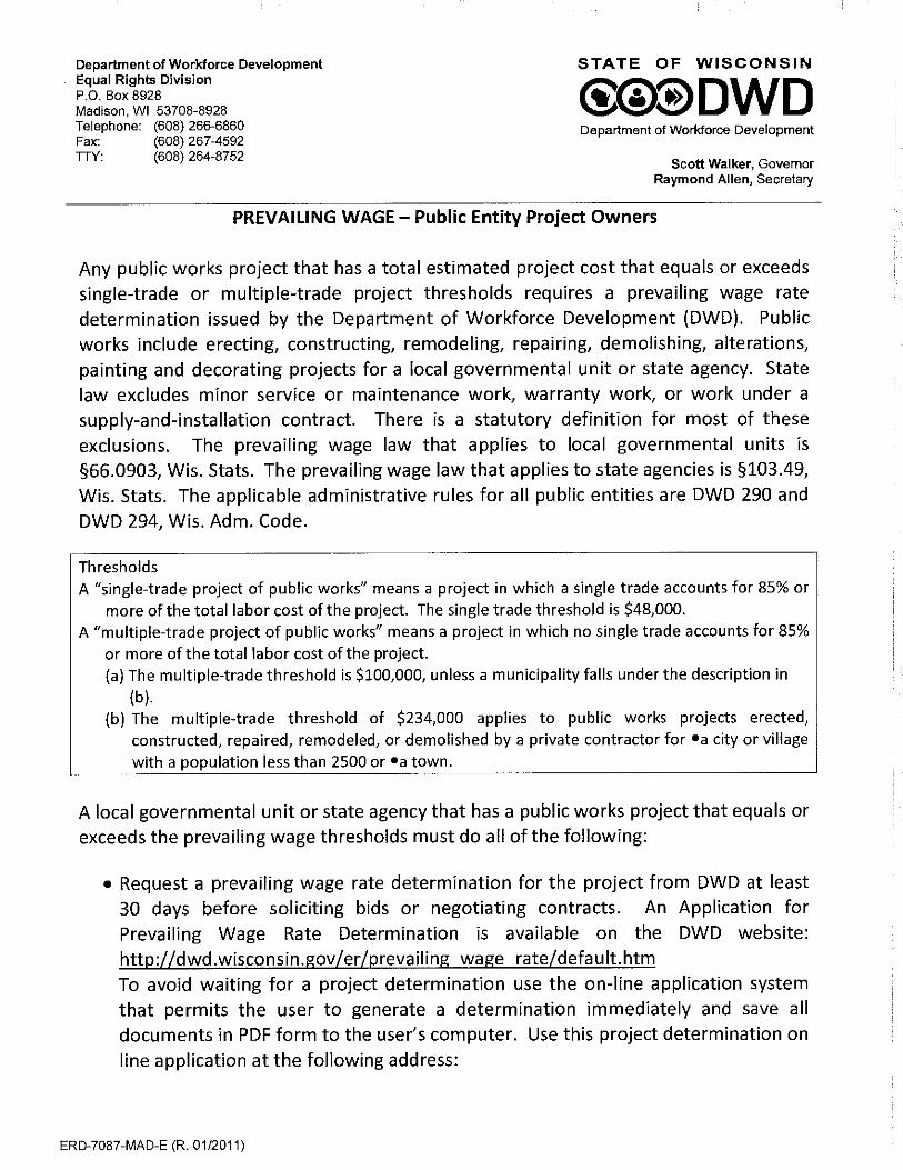
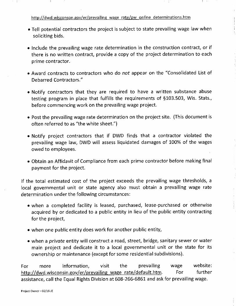


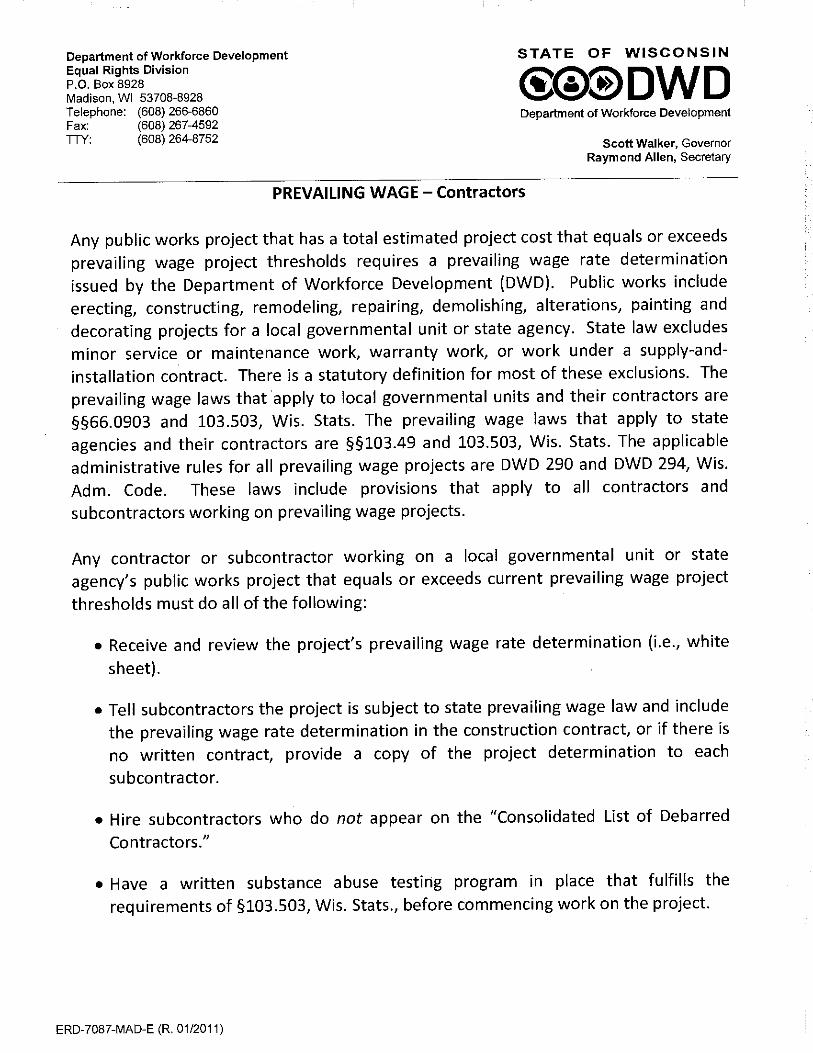


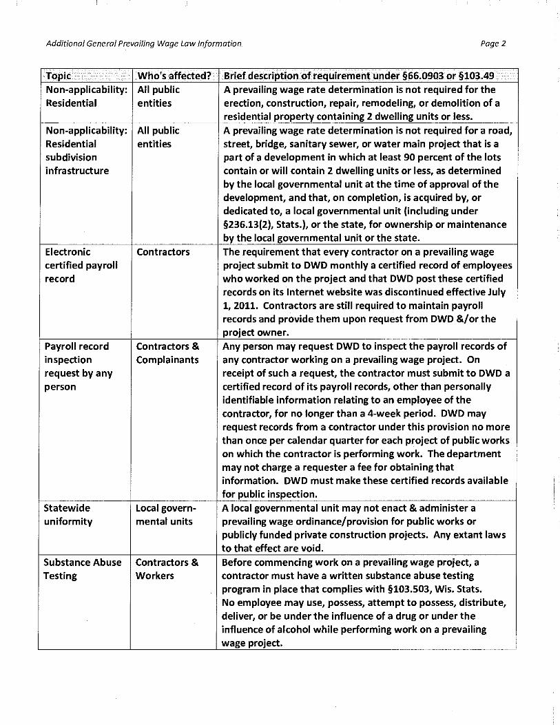
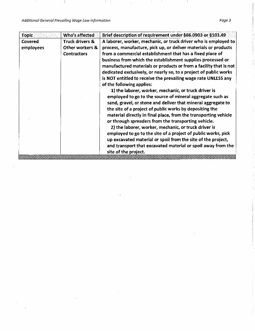

Certificate of Substantial Completion
Project: 2016 SANITARY SEWER REHABILITATION PROGRAM
Engineer’s Project No.: 16107
Owner: OAK CREEK WATER AND SEWER UTILITY
Owner’s Contract No.:
Contractor: Contract: This Certificate of Substantial Completion applies to: All Work under the Contract Documents: The following specified portions of the Work: ________________________________________________________________________________ ________________________________________________________________________________ ________________________________________________________________________________
May 19, 2017 Date of Substantial Completion
The Work to which this Certificate applies has been inspected by authorized representatives of Owner, Contractor, and Engineer, and found to be substantially complete in accordance with the Contract Documents. A list of items to be completed was previously provided to the Contractor. The list may not be all-inclusive, and the failure to include any items on such list does not alter the responsibility of the Contractor to complete all Work in accordance with the Contract Documents. The responsibilities between Owner and Contractor for security, operation, safety, maintenance, heat, utilities, insurance and warranties shall be as provided in the Contract Documents except as amended as follows: Amended Responsibilities Not Amended Owner’s Amended Responsibilities: ________________________________________________________________________________ ________________________________________________________________________________ ________________________________________________________________________________ Contractor’s Amended Responsibilities: ________________________________________________________________________________ ________________________________________________________________________________ ________________________________________________________________________________ The following documents are attached to and made part of this Certificate: ________________________________________________________________________________ ________________________________________________________________________________ ________________________________________________________________________________
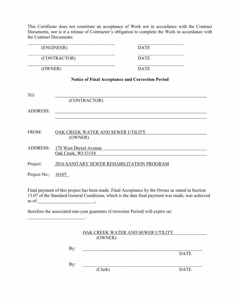
This Certificate does not constitute an acceptance of Work not in accordance with the Contract Documents, nor is it a release of Contractor’s obligation to complete the Work in accordance with the Contract Documents: ______________________________________ ____________________
(ENGINEER) DATE ______________________________________ ____________________
(CONTRACTOR) DATE ______________________________________ ____________________
(OWNER) DATE
Notice of Final Acceptance and Correction Period TO: (CONTRACTOR) ADDRESS: FROM: OAK CREEK WATER AND SEWER UTILITY (OWNER) ADDRESS: 170 West Drexel Avenue Oak Creek, WI 53154 Project: 2016 SANITARY SEWER REHABILITATION PROGRAM Project No.: 16107 Final payment of this project has been made. Final Acceptance by the Owner as stated in Section 13.07 of the Standard General Conditions, which is the date final payment was made, was achieved as of:_________________________, therefore the associated one-year guarantee (Correction Period) will expire on: _________________________. OAK CREEK WATER AND SEWER UTILITY (OWNER)
By: ____________________________________________________ DATE
By: ____________________________________________________ (Clerk) DATE

Contractor's Application for Payment No.Application Period: Application Date:
To (Owner): From (Contractor): Via (Engineer):
Project: Contract:
Owner's Contract No.: Contractor's Project No.: Engineer's Project No.:
1. ORIGINAL CONTRACT PRICE................................................................... $
2. Net change by Change Orders.......................................................................... $
3. Current Contract Price (Line 1 ± 2)................................................................. $
4. TOTAL COMPLETED AND STORED TO DATE
(Column F on Progress Estimate)..................................................................... $
5. RETAINAGE:
a. 5% X Work Completed.......... $
b. X Stored Material............ $
c. Total Retainage (Line 5a + Line 5b)..................................... $
6. AMOUNT ELIGIBLE TO DATE (Line 4 - Line 5c)...................................... $
7. LESS PREVIOUS PAYMENTS (Line 6 from prior Application).................. $
8. AMOUNT DUE THIS APPLICATION.......................................................... $
9. BALANCE TO FINISH, PLUS RETAINAGE
(Column G on Progress Estimate + Line 5 above)............................................ $
Contractor's Certification
Payment of: $
is recommended by:
Payment of: $
is approved by:
By: Date: Approved by:
Number Deductions
Change Order Summary
NET CHANGE BY
Approved Change Orders
TOTALS
CHANGE ORDERS
Additions
Application For Payment
Endorsed by the Construction Specifications Institute.
(Line 8 or other - attach explanation of the other amount)
(Date)
Funding Agency (if applicable) (Date)
(Line 8 or other - attach explanation of the other amount)
(Engineer)
(Owner)
(Date)
thru
The undersigned Contractor certifies that to the best of its knowledge: (1) all previous progress payments received from Owner on account of Work done under the Contract have been applied on account to discharge Contractor's legitimate obligations incurred in connection with Work covered by prior Applications for Payment; (2) title of all Work, materials and equipment incorporated in said Work or otherwise listed in or covered by this Application for Payment will pass to Owner at time of payment free and clear of all Liens, security interests and encumbrances (except such as are covered by a Bond acceptable to Owner indemnifying Owner against any such Liens, security interest or encumbrances); and (3) all Work covered by this Application for Payment is in accordance with the Contract Documents and is not defective.
EJCDC C-620 Contractor's Application for Payment© 2007 National Society of Professional Engineers for EJCDC. All rights reserved.
Page 1

Progress EstimateFor (contract): Application Number:
Application Period: Application Date:
Item C D Materials Presently Total Completed Balance to FinishThis Period Stored (not in C or D) and Stored to Date (B - F)
(C + D + E)From Previous Application
(C+D)
Work CompletedB F
Scheduled Value
Contractor's Application
Totals
% (F) B
A GE
Specification Section No. Description
EJCDC C-620 Contractor's Application for Payment© 2007 National Society of Professional Engineers for EJCDC. All rights reserved.
Page 2
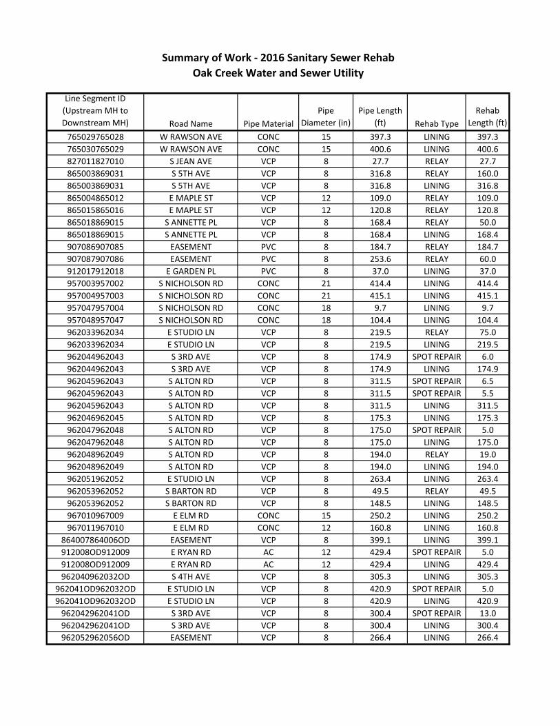
Line Segment ID
(Upstream MH to
Downstream MH) Road Name Pipe Material
Pipe
Diameter (in)
Pipe Length
(ft) Rehab Type
Rehab
Length (ft)
765029765028 W RAWSON AVE CONC 15 397.3 LINING 397.3
765030765029 W RAWSON AVE CONC 15 400.6 LINING 400.6
827011827010 S JEAN AVE VCP 8 27.7 RELAY 27.7
865003869031 S 5TH AVE VCP 8 316.8 RELAY 160.0
865003869031 S 5TH AVE VCP 8 316.8 LINING 316.8
865004865012 E MAPLE ST VCP 12 109.0 RELAY 109.0
865015865016 E MAPLE ST VCP 12 120.8 RELAY 120.8
865018869015 S ANNETTE PL VCP 8 168.4 RELAY 50.0
865018869015 S ANNETTE PL VCP 8 168.4 LINING 168.4
907086907085 EASEMENT PVC 8 184.7 RELAY 184.7
907087907086 EASEMENT PVC 8 253.6 RELAY 60.0
912017912018 E GARDEN PL PVC 8 37.0 LINING 37.0
957003957002 S NICHOLSON RD CONC 21 414.4 LINING 414.4
957004957003 S NICHOLSON RD CONC 21 415.1 LINING 415.1
957047957004 S NICHOLSON RD CONC 18 9.7 LINING 9.7
957048957047 S NICHOLSON RD CONC 18 104.4 LINING 104.4
962033962034 E STUDIO LN VCP 8 219.5 RELAY 75.0
962033962034 E STUDIO LN VCP 8 219.5 LINING 219.5
962044962043 S 3RD AVE VCP 8 174.9 SPOT REPAIR 6.0
962044962043 S 3RD AVE VCP 8 174.9 LINING 174.9
962045962043 S ALTON RD VCP 8 311.5 SPOT REPAIR 6.5
962045962043 S ALTON RD VCP 8 311.5 SPOT REPAIR 5.5
962045962043 S ALTON RD VCP 8 311.5 LINING 311.5
962046962045 S ALTON RD VCP 8 175.3 LINING 175.3
962047962048 S ALTON RD VCP 8 175.0 SPOT REPAIR 5.0
962047962048 S ALTON RD VCP 8 175.0 LINING 175.0
962048962049 S ALTON RD VCP 8 194.0 RELAY 19.0
962048962049 S ALTON RD VCP 8 194.0 LINING 194.0
962051962052 E STUDIO LN VCP 8 263.4 LINING 263.4
962053962052 S BARTON RD VCP 8 49.5 RELAY 49.5
962053962052 S BARTON RD VCP 8 148.5 LINING 148.5
967010967009 E ELM RD CONC 15 250.2 LINING 250.2
967011967010 E ELM RD CONC 12 160.8 LINING 160.8
864007864006OD EASEMENT VCP 8 399.1 LINING 399.1
912008OD912009 E RYAN RD AC 12 429.4 SPOT REPAIR 5.0
912008OD912009 E RYAN RD AC 12 429.4 LINING 429.4
962040962032OD S 4TH AVE VCP 8 305.3 LINING 305.3
962041OD962032OD E STUDIO LN VCP 8 420.9 SPOT REPAIR 5.0
962041OD962032OD E STUDIO LN VCP 8 420.9 LINING 420.9
962042962041OD S 3RD AVE VCP 8 300.4 SPOT REPAIR 13.0
962042962041OD S 3RD AVE VCP 8 300.4 LINING 300.4
962052962056OD EASEMENT VCP 8 266.4 LINING 266.4
Summary of Work - 2016 Sanitary Sewer Rehab
Oak Creek Water and Sewer Utility

***OFFICE USE ONLY***
Approved by: __________________________________________________________________ Date: ___________________________ City Engineer
Permit Fee $_______________ + Administrative Fee $5 = Total Fee $_______________
Name and Address of Applicant Address of Proposed Work
Starting Date Completion Date
Applicant Phone number
Email of Applicant Project number (if any)
Description of work (type of construction, lineal feet of excavation, etc.)
It is understood and agreed that this approval shall be subject to the applicant’s full compliance with the pertinent statutes and law, as well as the codes, rules, and regulations of jurisdictional agencies, and with all standard and special provisions, attached drawings, and notes. Accomplishment of any part of the permitted work shall evidence the applicant’s agreement to fully comply with and be bound by the permit in all its parts.
By: ______________________________________________________ _________________________________________ _______________________ Signature of applicant Title Date
PERMIT CONDITIONS AND PROVISIONS
This permit is granted to allow performance of the specific work described below. The following standard provisions and included special provisions shall govern.
1. All operations shall be performed without closing any street traffic lane, except as may be specifically sanctioned by the City. Unless otherwise authorized, full two-way traffic shall be maintained at all times. Signs which conform in design and location to the specifications and details in the current Wisconsin Manual of Traffic Control Devices shall be erected and in place at all times while operations are in progress which will affect traffic. Such signing shall be supplemented by proper barricades, light and/or flagmen when the natures of the operation or the conditions of visibility are such that these further safety precautions are necessary.
2. All roadways, shoulders, paved areas, driveways, grassed areas, etc. in public or private ways shall be replaced equal to or better than the condition existingbefore the work commenced.
3. All refuse, excess dirt, and materials shall be removed from the site and the site restored to original condition as the work progresses or immediately upon itscompletion.
4. Private drives and roadways shall not remain closed overnight, over weekends, or holidays. Before obstructing or closing any private drives or roadways, owner, or occupant shall be notified.
5. The holder of this permit shall assume all liability and responsibility for any and all damage resulting from this work, and shall maintain suitable barriers and warning devices along the work until the work is completed.
6. Gutters and drainage ditches shall remain open at all times, or provision to permit proper drainage during work progress, and shall be restored to their original condition as the work progresses or immediately upon its completion.
7. Final approval and release shall not be granted until the Engineering Division grants approval.
8. The permittee shall provide his supervisor with a copy of this permit, and shall assure the supervisor’s familiarity with all details and requirements thereof. Such permit copy shall be in the keeping of the supervisor and at the site of the work at all times while work operations are in active process, and shall be provided for examination by City inspection personnel upon request.
9. If work is not commenced within 60 days of permit issuance, the permit shall automatically expire, and a new permit shall be obtained, and additional fee charged.
10. No excavation shall remain open in excess of 3 calendar days.
11. The permittee shall guarantee and maintain the site of the excavation for 1 year after restoring it to its original condition.
Parcel No. __________________________
Permit No. __________________________ PUBLIC RIGHT-OF-WAY EXCAVATION PERMIT

DRAWINGS
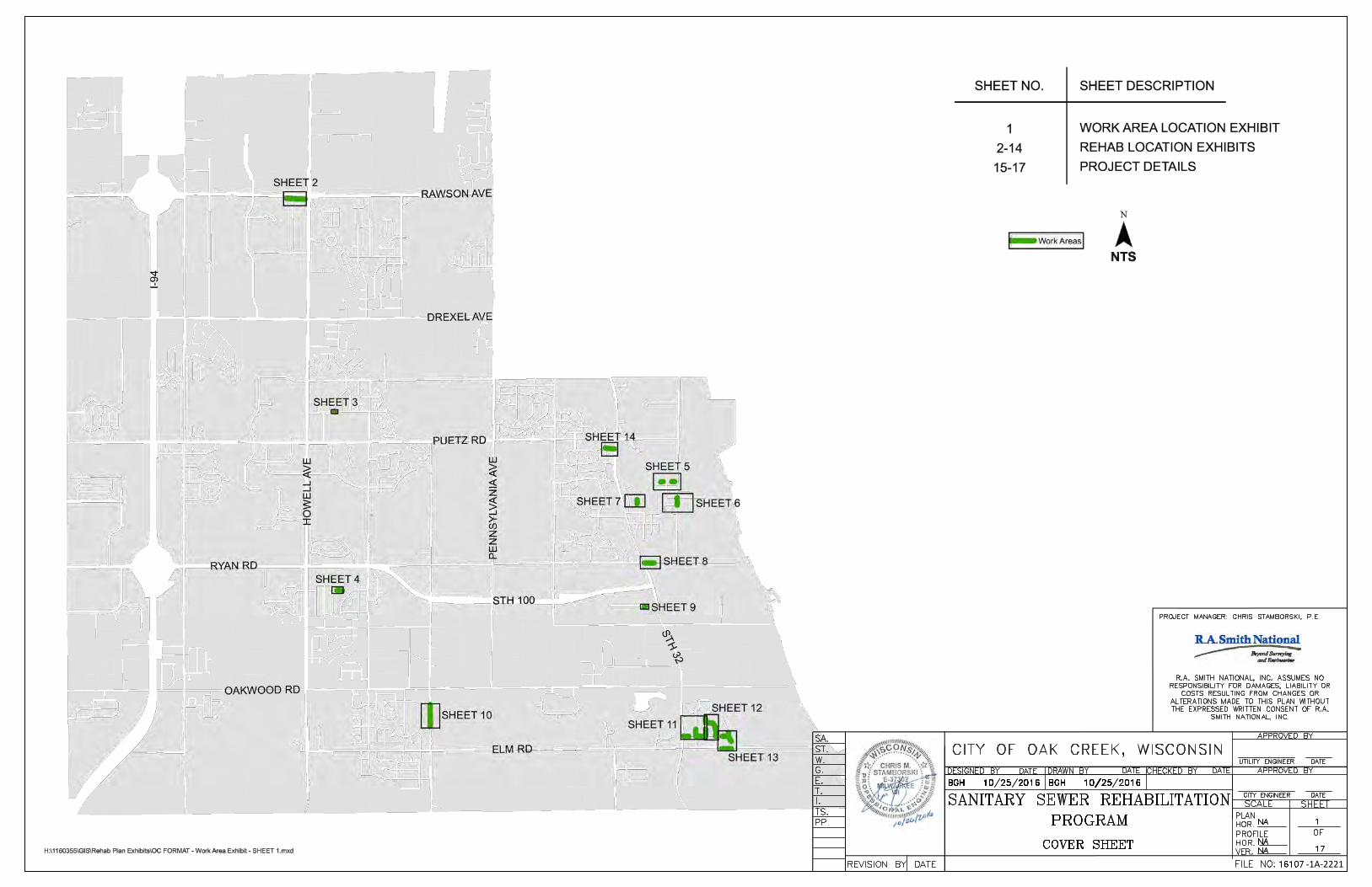
-1A-2221
AutoCAD SHX Text
FILE NO:
AutoCAD SHX Text
OF
AutoCAD SHX Text
VER.
AutoCAD SHX Text
HOR.
AutoCAD SHX Text
PROFILE
AutoCAD SHX Text
HOR.
AutoCAD SHX Text
PLAN
AutoCAD SHX Text
DATE
AutoCAD SHX Text
CITY ENGINEER
AutoCAD SHX Text
SHEET
AutoCAD SHX Text
SCALE
AutoCAD SHX Text
APPROVED BY
AutoCAD SHX Text
DATE
AutoCAD SHX Text
CHECKED BY
AutoCAD SHX Text
DATE
AutoCAD SHX Text
DRAWN BY
AutoCAD SHX Text
DATE
AutoCAD SHX Text
DESIGNED BY
AutoCAD SHX Text
DATE
AutoCAD SHX Text
REVISION BY
AutoCAD SHX Text
PP.
AutoCAD SHX Text
TS.
AutoCAD SHX Text
I.
AutoCAD SHX Text
T.
AutoCAD SHX Text
E.
AutoCAD SHX Text
G.
AutoCAD SHX Text
ST.
AutoCAD SHX Text
W.
AutoCAD SHX Text
SA.
AutoCAD SHX Text
CITY OF OAK CREEK, WISCONSIN
AutoCAD SHX Text
SANITARY SEWER REHABILITATION
AutoCAD SHX Text
1
AutoCAD SHX Text
17
AutoCAD SHX Text
NA
AutoCAD SHX Text
16107
AutoCAD SHX Text
BGH 10/25/2016
AutoCAD SHX Text
BGH 10/25/2016
AutoCAD SHX Text
NA
AutoCAD SHX Text
NA
AutoCAD SHX Text
APPROVED BY
AutoCAD SHX Text
UTILITY ENGINEER
AutoCAD SHX Text
DATE
AutoCAD SHX Text
PROGRAM
AutoCAD SHX Text
COVER SHEET
AutoCAD SHX Text
PROJECT MANAGER: CHRIS STAMBORSKI, P.E.
AutoCAD SHX Text
R.A. SMITH NATIONAL, INC. ASSUMES NO RESPONSIBILITY FOR DAMAGES, LIABILITY OR COSTS RESULTING FROM CHANGES OR ALTERATIONS MADE TO THIS PLAN WITHOUT THE EXPRESSED WRITTEN CONSENT OF R.A. SMITH NATIONAL, INC.
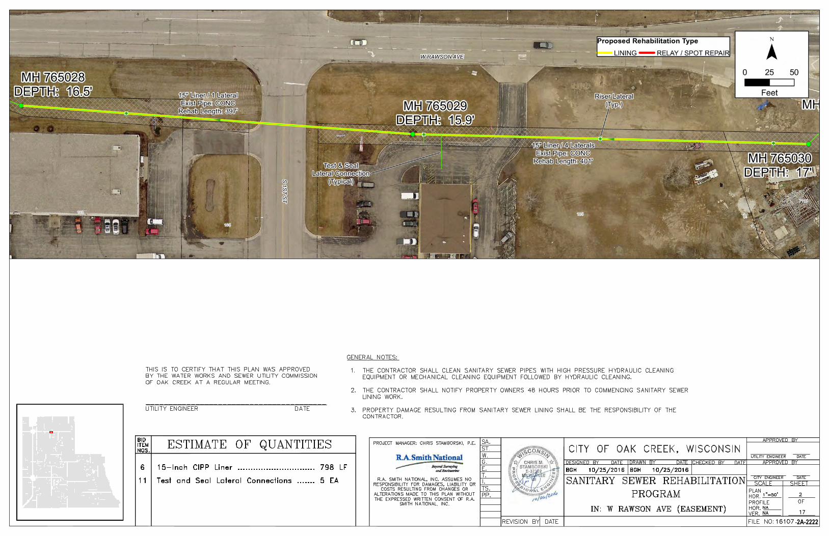
-2A-2222
AutoCAD SHX Text
FILE NO:
AutoCAD SHX Text
OF
AutoCAD SHX Text
VER.
AutoCAD SHX Text
HOR.
AutoCAD SHX Text
PROFILE
AutoCAD SHX Text
HOR.
AutoCAD SHX Text
PLAN
AutoCAD SHX Text
DATE
AutoCAD SHX Text
CITY ENGINEER
AutoCAD SHX Text
SHEET
AutoCAD SHX Text
SCALE
AutoCAD SHX Text
APPROVED BY
AutoCAD SHX Text
DATE
AutoCAD SHX Text
CHECKED BY
AutoCAD SHX Text
DATE
AutoCAD SHX Text
DRAWN BY
AutoCAD SHX Text
DATE
AutoCAD SHX Text
DESIGNED BY
AutoCAD SHX Text
DATE
AutoCAD SHX Text
REVISION BY
AutoCAD SHX Text
PP.
AutoCAD SHX Text
TS.
AutoCAD SHX Text
I.
AutoCAD SHX Text
T.
AutoCAD SHX Text
E.
AutoCAD SHX Text
G.
AutoCAD SHX Text
ST.
AutoCAD SHX Text
W.
AutoCAD SHX Text
SA.
AutoCAD SHX Text
CITY OF OAK CREEK, WISCONSIN
AutoCAD SHX Text
SANITARY SEWER REHABILITATION
AutoCAD SHX Text
2
AutoCAD SHX Text
17
AutoCAD SHX Text
1"=50'
AutoCAD SHX Text
BGH 10/25/2016
AutoCAD SHX Text
BGH 10/25/2016
AutoCAD SHX Text
NA
AutoCAD SHX Text
NA
AutoCAD SHX Text
APPROVED BY
AutoCAD SHX Text
UTILITY ENGINEER
AutoCAD SHX Text
DATE
AutoCAD SHX Text
PROGRAM
AutoCAD SHX Text
IN: W RAWSON AVE (EASEMENT)
AutoCAD SHX Text
ITEM
AutoCAD SHX Text
BID
AutoCAD SHX Text
NOS.
AutoCAD SHX Text
ESTIMATE OF QUANTITIES
AutoCAD SHX Text
6
AutoCAD SHX Text
15-Inch CIPP Liner .............................. 798 LF
AutoCAD SHX Text
THIS IS TO CERTIFY THAT THIS PLAN WAS APPROVED BY THE WATER WORKS AND SEWER UTILITY COMMISSION OF OAK CREEK AT A REGULAR MEETING. ________________________________________ UTILITY ENGINEER DATE
AutoCAD SHX Text
PROJECT MANAGER: CHRIS STAMBORSKI, P.E.
AutoCAD SHX Text
R.A. SMITH NATIONAL, INC. ASSUMES NO RESPONSIBILITY FOR DAMAGES, LIABILITY OR COSTS RESULTING FROM CHANGES OR ALTERATIONS MADE TO THIS PLAN WITHOUT THE EXPRESSED WRITTEN CONSENT OF R.A. SMITH NATIONAL, INC.
AutoCAD SHX Text
16107
AutoCAD SHX Text
11
AutoCAD SHX Text
Test and Seal Lateral Connections ....... 5 EA
AutoCAD SHX Text
GENERAL NOTES: 1.THE CONTRACTOR SHALL CLEAN SANITARY SEWER PIPES WITH HIGH PRESSURE HYDRAULIC CLEANING THE CONTRACTOR SHALL CLEAN SANITARY SEWER PIPES WITH HIGH PRESSURE HYDRAULIC CLEANING EQUIPMENT OR MECHANICAL CLEANING EQUIPMENT FOLLOWED BY HYDRAULIC CLEANING. 2.THE CONTRACTOR SHALL NOTIFY PROPERTY OWNERS 48 HOURS PRIOR TO COMMENCING SANITARY SEWER THE CONTRACTOR SHALL NOTIFY PROPERTY OWNERS 48 HOURS PRIOR TO COMMENCING SANITARY SEWER LINING WORK. 3.PROPERTY DAMAGE RESULTING FROM SANITARY SEWER LINING SHALL BE THE RESPONSIBILITY OF THE PROPERTY DAMAGE RESULTING FROM SANITARY SEWER LINING SHALL BE THE RESPONSIBILITY OF THE CONTRACTOR.
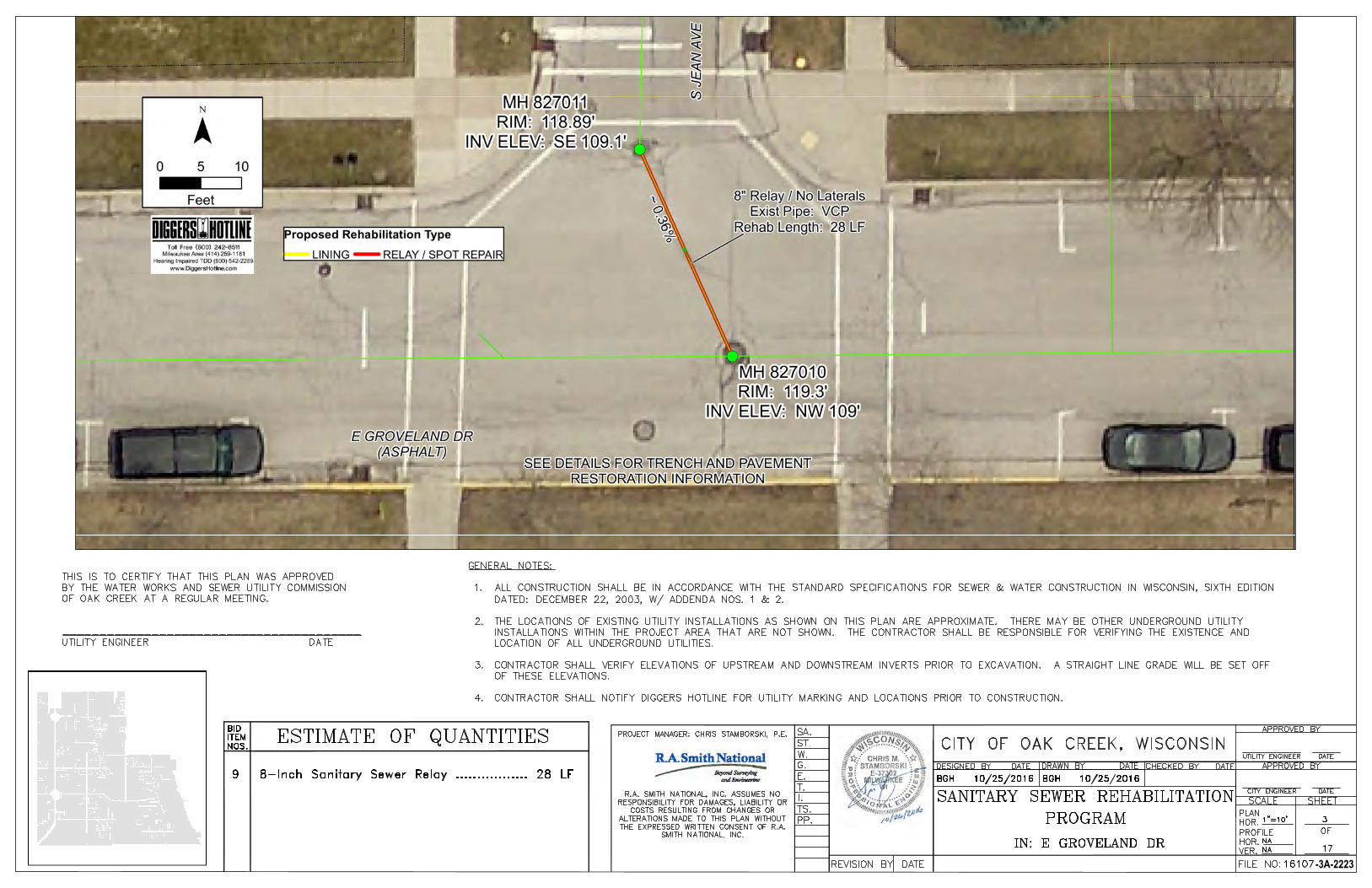
-3A-2223
AutoCAD SHX Text
FILE NO:
AutoCAD SHX Text
OF
AutoCAD SHX Text
VER.
AutoCAD SHX Text
HOR.
AutoCAD SHX Text
PROFILE
AutoCAD SHX Text
HOR.
AutoCAD SHX Text
PLAN
AutoCAD SHX Text
DATE
AutoCAD SHX Text
CITY ENGINEER
AutoCAD SHX Text
SHEET
AutoCAD SHX Text
SCALE
AutoCAD SHX Text
APPROVED BY
AutoCAD SHX Text
DATE
AutoCAD SHX Text
CHECKED BY
AutoCAD SHX Text
DATE
AutoCAD SHX Text
DRAWN BY
AutoCAD SHX Text
DATE
AutoCAD SHX Text
DESIGNED BY
AutoCAD SHX Text
DATE
AutoCAD SHX Text
REVISION BY
AutoCAD SHX Text
PP.
AutoCAD SHX Text
TS.
AutoCAD SHX Text
I.
AutoCAD SHX Text
T.
AutoCAD SHX Text
E.
AutoCAD SHX Text
G.
AutoCAD SHX Text
ST.
AutoCAD SHX Text
W.
AutoCAD SHX Text
SA.
AutoCAD SHX Text
CITY OF OAK CREEK, WISCONSIN
AutoCAD SHX Text
SANITARY SEWER REHABILITATION
AutoCAD SHX Text
3
AutoCAD SHX Text
17
AutoCAD SHX Text
1"=10'
AutoCAD SHX Text
BGH 10/25/2016
AutoCAD SHX Text
BGH 10/25/2016
AutoCAD SHX Text
NA
AutoCAD SHX Text
NA
AutoCAD SHX Text
APPROVED BY
AutoCAD SHX Text
UTILITY ENGINEER
AutoCAD SHX Text
DATE
AutoCAD SHX Text
PROGRAM
AutoCAD SHX Text
IN: E GROVELAND DR
AutoCAD SHX Text
ITEM
AutoCAD SHX Text
BID
AutoCAD SHX Text
NOS.
AutoCAD SHX Text
ESTIMATE OF QUANTITIES
AutoCAD SHX Text
9
AutoCAD SHX Text
8-Inch Sanitary Sewer Relay ................. 28 LF
AutoCAD SHX Text
GENERAL NOTES: 1.ALL CONSTRUCTION SHALL BE IN ACCORDANCE WITH THE STANDARD SPECIFICATIONS FOR SEWER & WATER CONSTRUCTION IN WISCONSIN, SIXTH EDITION ALL CONSTRUCTION SHALL BE IN ACCORDANCE WITH THE STANDARD SPECIFICATIONS FOR SEWER & WATER CONSTRUCTION IN WISCONSIN, SIXTH EDITION DATED: DECEMBER 22, 2003, W/ ADDENDA NOS. 1 & 2. 2.THE LOCATIONS OF EXISTING UTILITY INSTALLATIONS AS SHOWN ON THIS PLAN ARE APPROXIMATE. THERE MAY BE OTHER UNDERGROUND UTILITY THE LOCATIONS OF EXISTING UTILITY INSTALLATIONS AS SHOWN ON THIS PLAN ARE APPROXIMATE. THERE MAY BE OTHER UNDERGROUND UTILITY INSTALLATIONS WITHIN THE PROJECT AREA THAT ARE NOT SHOWN. THE CONTRACTOR SHALL BE RESPONSIBLE FOR VERIFYING THE EXISTENCE AND LOCATION OF ALL UNDERGROUND UTILITIES. 3.CONTRACTOR SHALL VERIFY ELEVATIONS OF UPSTREAM AND DOWNSTREAM INVERTS PRIOR TO EXCAVATION. A STRAIGHT LINE GRADE WILL BE SET OFF CONTRACTOR SHALL VERIFY ELEVATIONS OF UPSTREAM AND DOWNSTREAM INVERTS PRIOR TO EXCAVATION. A STRAIGHT LINE GRADE WILL BE SET OFF OF THESE ELEVATIONS. 4.CONTRACTOR SHALL NOTIFY DIGGERS HOTLINE FOR UTILITY MARKING AND LOCATIONS PRIOR TO CONSTRUCTION.CONTRACTOR SHALL NOTIFY DIGGERS HOTLINE FOR UTILITY MARKING AND LOCATIONS PRIOR TO CONSTRUCTION.
AutoCAD SHX Text
THIS IS TO CERTIFY THAT THIS PLAN WAS APPROVED BY THE WATER WORKS AND SEWER UTILITY COMMISSION OF OAK CREEK AT A REGULAR MEETING. ________________________________________ UTILITY ENGINEER DATE
AutoCAD SHX Text
PROJECT MANAGER: CHRIS STAMBORSKI, P.E.
AutoCAD SHX Text
R.A. SMITH NATIONAL, INC. ASSUMES NO RESPONSIBILITY FOR DAMAGES, LIABILITY OR COSTS RESULTING FROM CHANGES OR ALTERATIONS MADE TO THIS PLAN WITHOUT THE EXPRESSED WRITTEN CONSENT OF R.A. SMITH NATIONAL, INC.
AutoCAD SHX Text
16107
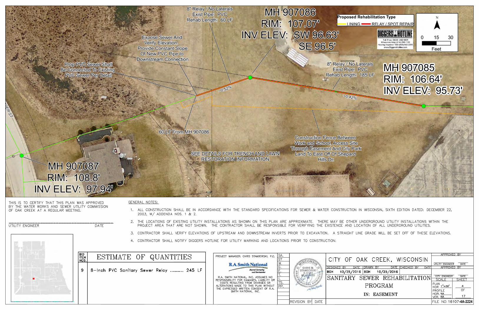
-4A-2224
AutoCAD SHX Text
FILE NO:
AutoCAD SHX Text
OF
AutoCAD SHX Text
VER.
AutoCAD SHX Text
HOR.
AutoCAD SHX Text
PROFILE
AutoCAD SHX Text
HOR.
AutoCAD SHX Text
PLAN
AutoCAD SHX Text
DATE
AutoCAD SHX Text
CITY ENGINEER
AutoCAD SHX Text
SHEET
AutoCAD SHX Text
SCALE
AutoCAD SHX Text
APPROVED BY
AutoCAD SHX Text
DATE
AutoCAD SHX Text
CHECKED BY
AutoCAD SHX Text
DATE
AutoCAD SHX Text
DRAWN BY
AutoCAD SHX Text
DATE
AutoCAD SHX Text
DESIGNED BY
AutoCAD SHX Text
DATE
AutoCAD SHX Text
REVISION BY
AutoCAD SHX Text
PP.
AutoCAD SHX Text
TS.
AutoCAD SHX Text
I.
AutoCAD SHX Text
T.
AutoCAD SHX Text
E.
AutoCAD SHX Text
G.
AutoCAD SHX Text
ST.
AutoCAD SHX Text
W.
AutoCAD SHX Text
SA.
AutoCAD SHX Text
CITY OF OAK CREEK, WISCONSIN
AutoCAD SHX Text
SANITARY SEWER REHABILITATION
AutoCAD SHX Text
4
AutoCAD SHX Text
17
AutoCAD SHX Text
1"=30'
AutoCAD SHX Text
BGH 10/25/2016
AutoCAD SHX Text
BGH 10/25/2016
AutoCAD SHX Text
NA
AutoCAD SHX Text
NA
AutoCAD SHX Text
APPROVED BY
AutoCAD SHX Text
UTILITY ENGINEER
AutoCAD SHX Text
DATE
AutoCAD SHX Text
PROGRAM
AutoCAD SHX Text
IN: EASEMENT
AutoCAD SHX Text
ITEM
AutoCAD SHX Text
BID
AutoCAD SHX Text
NOS.
AutoCAD SHX Text
ESTIMATE OF QUANTITIES
AutoCAD SHX Text
9
AutoCAD SHX Text
8-Inch PVC Sanitary Sewer Relay ......... 245 LF
AutoCAD SHX Text
GENERAL NOTES: 1.ALL CONSTRUCTION SHALL BE IN ACCORDANCE WITH THE STANDARD SPECIFICATIONS FOR SEWER & WATER CONSTRUCTION IN WISCONSIN, SIXTH EDITION DATED: DECEMBER 22, ALL CONSTRUCTION SHALL BE IN ACCORDANCE WITH THE STANDARD SPECIFICATIONS FOR SEWER & WATER CONSTRUCTION IN WISCONSIN, SIXTH EDITION DATED: DECEMBER 22, 2003, W/ ADDENDA NOS. 1 & 2. 2.THE LOCATIONS OF EXISTING UTILITY INSTALLATIONS AS SHOWN ON THIS PLAN ARE APPROXIMATE. THERE MAY BE OTHER UNDERGROUND UTILITY INSTALLATIONS WITHIN THE THE LOCATIONS OF EXISTING UTILITY INSTALLATIONS AS SHOWN ON THIS PLAN ARE APPROXIMATE. THERE MAY BE OTHER UNDERGROUND UTILITY INSTALLATIONS WITHIN THE PROJECT AREA THAT ARE NOT SHOWN. THE CONTRACTOR SHALL BE RESPONSIBLE FOR VERIFYING THE EXISTENCE AND LOCATION OF ALL UNDERGROUND UTILITIES. 3.CONTRACTOR SHALL VERIFY ELEVATIONS OF UPSTREAM AND DOWNSTREAM INVERTS PRIOR TO EXCAVATION. A STRAIGHT LINE GRADE WILL BE SET OFF OF THESE ELEVATIONS. CONTRACTOR SHALL VERIFY ELEVATIONS OF UPSTREAM AND DOWNSTREAM INVERTS PRIOR TO EXCAVATION. A STRAIGHT LINE GRADE WILL BE SET OFF OF THESE ELEVATIONS. 4.CONTRACTOR SHALL NOTIFY DIGGERS HOTLINE FOR UTILITY MARKING AND LOCATIONS PRIOR TO CONSTRUCTION.CONTRACTOR SHALL NOTIFY DIGGERS HOTLINE FOR UTILITY MARKING AND LOCATIONS PRIOR TO CONSTRUCTION.
AutoCAD SHX Text
THIS IS TO CERTIFY THAT THIS PLAN WAS APPROVED BY THE WATER WORKS AND SEWER UTILITY COMMISSION OF OAK CREEK AT A REGULAR MEETING. ________________________________________ UTILITY ENGINEER DATE
AutoCAD SHX Text
PROJECT MANAGER: CHRIS STAMBORSKI, P.E.
AutoCAD SHX Text
R.A. SMITH NATIONAL, INC. ASSUMES NO RESPONSIBILITY FOR DAMAGES, LIABILITY OR COSTS RESULTING FROM CHANGES OR ALTERATIONS MADE TO THIS PLAN WITHOUT THE EXPRESSED WRITTEN CONSENT OF R.A. SMITH NATIONAL, INC.
AutoCAD SHX Text
16107

-5A-2225
AutoCAD SHX Text
FILE NO:
AutoCAD SHX Text
OF
AutoCAD SHX Text
VER.
AutoCAD SHX Text
HOR.
AutoCAD SHX Text
PROFILE
AutoCAD SHX Text
HOR.
AutoCAD SHX Text
PLAN
AutoCAD SHX Text
DATE
AutoCAD SHX Text
CITY ENGINEER
AutoCAD SHX Text
SHEET
AutoCAD SHX Text
SCALE
AutoCAD SHX Text
APPROVED BY
AutoCAD SHX Text
DATE
AutoCAD SHX Text
CHECKED BY
AutoCAD SHX Text
DATE
AutoCAD SHX Text
DRAWN BY
AutoCAD SHX Text
DATE
AutoCAD SHX Text
DESIGNED BY
AutoCAD SHX Text
DATE
AutoCAD SHX Text
REVISION BY
AutoCAD SHX Text
PP.
AutoCAD SHX Text
TS.
AutoCAD SHX Text
I.
AutoCAD SHX Text
T.
AutoCAD SHX Text
E.
AutoCAD SHX Text
G.
AutoCAD SHX Text
ST.
AutoCAD SHX Text
W.
AutoCAD SHX Text
SA.
AutoCAD SHX Text
CITY OF OAK CREEK, WISCONSIN
AutoCAD SHX Text
SANITARY SEWER REHABILITATION
AutoCAD SHX Text
5
AutoCAD SHX Text
17
AutoCAD SHX Text
1"=40'
AutoCAD SHX Text
BGH 10/25/2016
AutoCAD SHX Text
BGH 10/25/2016
AutoCAD SHX Text
NA
AutoCAD SHX Text
NA
AutoCAD SHX Text
APPROVED BY
AutoCAD SHX Text
UTILITY ENGINEER
AutoCAD SHX Text
DATE
AutoCAD SHX Text
PROGRAM
AutoCAD SHX Text
IN: MAPLE ST
AutoCAD SHX Text
ITEM
AutoCAD SHX Text
BID
AutoCAD SHX Text
NOS.
AutoCAD SHX Text
ESTIMATE OF QUANTITIES
AutoCAD SHX Text
3
AutoCAD SHX Text
6-Inch PVC Sanitary Lateral Relay .......... 30 LF
AutoCAD SHX Text
GENERAL NOTES: 1.ALL CONSTRUCTION SHALL BE IN ACCORDANCE WITH THE STANDARD SPECIFICATIONS FOR SEWER & WATER CONSTRUCTION IN WISCONSIN, ALL CONSTRUCTION SHALL BE IN ACCORDANCE WITH THE STANDARD SPECIFICATIONS FOR SEWER & WATER CONSTRUCTION IN WISCONSIN, SIXTH EDITION DATED: DECEMBER 22, 2003, W/ ADDENDA NOS. 1 & 2. 2.THE LOCATIONS OF EXISTING UTILITY INSTALLATIONS AS SHOWN ON THIS PLAN ARE APPROXIMATE. THERE MAY BE OTHER UNDERGROUND THE LOCATIONS OF EXISTING UTILITY INSTALLATIONS AS SHOWN ON THIS PLAN ARE APPROXIMATE. THERE MAY BE OTHER UNDERGROUND UTILITY INSTALLATIONS WITHIN THE PROJECT AREA THAT ARE NOT SHOWN. THE CONTRACTOR SHALL BE RESPONSIBLE FOR VERIFYING THE EXISTENCE AND LOCATION OF ALL UNDERGROUND UTILITIES. 3.CONTRACTOR SHALL VERIFY ELEVATIONS OF UPSTREAM AND DOWNSTREAM INVERTS PRIOR TO EXCAVATION. A STRAIGHT LINE GRADE WILL CONTRACTOR SHALL VERIFY ELEVATIONS OF UPSTREAM AND DOWNSTREAM INVERTS PRIOR TO EXCAVATION. A STRAIGHT LINE GRADE WILL BE SET OFF OF THESE ELEVATIONS. 4.CONTRACTOR SHALL NOTIFY DIGGERS HOTLINE FOR UTILITY MARKING AND LOCATIONS PRIOR TO CONSTRUCTION.CONTRACTOR SHALL NOTIFY DIGGERS HOTLINE FOR UTILITY MARKING AND LOCATIONS PRIOR TO CONSTRUCTION.
AutoCAD SHX Text
THIS IS TO CERTIFY THAT THIS PLAN WAS APPROVED BY THE WATER WORKS AND SEWER UTILITY COMMISSION OF OAK CREEK AT A REGULAR MEETING. ________________________________________ UTILITY ENGINEER DATE
AutoCAD SHX Text
PROJECT MANAGER: CHRIS STAMBORSKI, P.E.
AutoCAD SHX Text
R.A. SMITH NATIONAL, INC. ASSUMES NO RESPONSIBILITY FOR DAMAGES, LIABILITY OR COSTS RESULTING FROM CHANGES OR ALTERATIONS MADE TO THIS PLAN WITHOUT THE EXPRESSED WRITTEN CONSENT OF R.A. SMITH NATIONAL, INC.
AutoCAD SHX Text
16107
AutoCAD SHX Text
10
AutoCAD SHX Text
12-Inch PVC Sanitary Sewer Relay ........ 230 LF

-6A-2226
AutoCAD SHX Text
FILE NO:
AutoCAD SHX Text
OF
AutoCAD SHX Text
VER.
AutoCAD SHX Text
HOR.
AutoCAD SHX Text
PROFILE
AutoCAD SHX Text
HOR.
AutoCAD SHX Text
PLAN
AutoCAD SHX Text
DATE
AutoCAD SHX Text
CITY ENGINEER
AutoCAD SHX Text
SHEET
AutoCAD SHX Text
SCALE
AutoCAD SHX Text
APPROVED BY
AutoCAD SHX Text
DATE
AutoCAD SHX Text
CHECKED BY
AutoCAD SHX Text
DATE
AutoCAD SHX Text
DRAWN BY
AutoCAD SHX Text
DATE
AutoCAD SHX Text
DESIGNED BY
AutoCAD SHX Text
DATE
AutoCAD SHX Text
REVISION BY
AutoCAD SHX Text
PP.
AutoCAD SHX Text
TS.
AutoCAD SHX Text
I.
AutoCAD SHX Text
T.
AutoCAD SHX Text
E.
AutoCAD SHX Text
G.
AutoCAD SHX Text
ST.
AutoCAD SHX Text
W.
AutoCAD SHX Text
SA.
AutoCAD SHX Text
CITY OF OAK CREEK, WISCONSIN
AutoCAD SHX Text
SANITARY SEWER REHABILITATION
AutoCAD SHX Text
6
AutoCAD SHX Text
17
AutoCAD SHX Text
1"=50'
AutoCAD SHX Text
BGH 10/25/2016
AutoCAD SHX Text
BGH 10/25/2016
AutoCAD SHX Text
NA
AutoCAD SHX Text
NA
AutoCAD SHX Text
APPROVED BY
AutoCAD SHX Text
UTILITY ENGINEER
AutoCAD SHX Text
DATE
AutoCAD SHX Text
PROGRAM
AutoCAD SHX Text
IN: 5 AVE
AutoCAD SHX Text
ITEM
AutoCAD SHX Text
BID
AutoCAD SHX Text
NOS.
AutoCAD SHX Text
ESTIMATE OF QUANTITIES
AutoCAD SHX Text
3
AutoCAD SHX Text
6-Inch PVC Sanitary Lateral Relay .......... 15 LF
AutoCAD SHX Text
GENERAL NOTES: 1.ALL CONSTRUCTION SHALL BE IN ACCORDANCE WITH ALL CONSTRUCTION SHALL BE IN ACCORDANCE WITH THE STANDARD SPECIFICATIONS FOR SEWER & WATER CONSTRUCTION IN WISCONSIN, SIXTH EDITION DATED: DECEMBER 22, 2003, W/ ADDENDA NOS. 1 & 2. 2.THE LOCATIONS OF EXISTING UTILITY INSTALLATIONS AS THE LOCATIONS OF EXISTING UTILITY INSTALLATIONS AS SHOWN ON THIS PLAN ARE APPROXIMATE. THERE MAY BE OTHER UNDERGROUND UTILITY INSTALLATIONS WITHIN THE PROJECT AREA THAT ARE NOT SHOWN. THE CONTRACTOR SHALL BE RESPONSIBLE FOR VERIFYING THE EXISTENCE AND LOCATION OF ALL UNDERGROUND UTILITIES. 3.CONTRACTOR SHALL VERIFY ELEVATIONS OF UPSTREAM CONTRACTOR SHALL VERIFY ELEVATIONS OF UPSTREAM AND DOWNSTREAM INVERTS PRIOR TO EXCAVATION. A STRAIGHT LINE GRADE WILL BE SET OFF OF THESE ELEVATIONS. 4.CONTRACTOR SHALL NOTIFY DIGGERS HOTLINE FOR CONTRACTOR SHALL NOTIFY DIGGERS HOTLINE FOR UTILITY MARKING AND LOCATIONS PRIOR TO CONSTRUCTION. 5.THE CONTRACTOR SHALL CLEAN SANITARY SEWER THE CONTRACTOR SHALL CLEAN SANITARY SEWER PIPES WITH HIGH PRESSURE HYDRAULIC CLEANING EQUIPMENT OR MECHANICAL CLEANING EQUIPMENT FOLLOWED BY HYDRAULIC CLEANING. 6.THE CONTRACTOR SHALL NOTIFY PROPERTY OWNERS THE CONTRACTOR SHALL NOTIFY PROPERTY OWNERS 48 HOURS PRIOR TO COMMENCING SANITARY SEWER LINING WORK. 7.PROPERTY DAMAGE RESULTING FROM SANITARY SEWER PROPERTY DAMAGE RESULTING FROM SANITARY SEWER LINING SHALL BE THE RESPONSIBILITY OF THE CONTRACTOR.
AutoCAD SHX Text
THIS IS TO CERTIFY THAT THIS PLAN WAS APPROVED BY THE WATER WORKS AND SEWER UTILITY COMMISSION OF OAK CREEK AT A REGULAR MEETING. ________________________________________ UTILITY ENGINEER DATE
AutoCAD SHX Text
PROJECT MANAGER: CHRIS STAMBORSKI, P.E.
AutoCAD SHX Text
R.A. SMITH NATIONAL, INC. ASSUMES NO RESPONSIBILITY FOR DAMAGES, LIABILITY OR COSTS RESULTING FROM CHANGES OR ALTERATIONS MADE TO THIS PLAN WITHOUT THE EXPRESSED WRITTEN CONSENT OF R.A. SMITH NATIONAL, INC.
AutoCAD SHX Text
16107
AutoCAD SHX Text
4
AutoCAD SHX Text
8-Inch CIPP LINER ................................. 317 LF
AutoCAD SHX Text
9
AutoCAD SHX Text
8-Inch PVC Sanitary Sewer Relay .......... 160 LF
AutoCAD SHX Text
11
AutoCAD SHX Text
Test and Seal Lateral Connections ............ 8 EA

-7A-2227
AutoCAD SHX Text
FILE NO:
AutoCAD SHX Text
OF
AutoCAD SHX Text
VER.
AutoCAD SHX Text
HOR.
AutoCAD SHX Text
PROFILE
AutoCAD SHX Text
HOR.
AutoCAD SHX Text
PLAN
AutoCAD SHX Text
DATE
AutoCAD SHX Text
CITY ENGINEER
AutoCAD SHX Text
SHEET
AutoCAD SHX Text
SCALE
AutoCAD SHX Text
APPROVED BY
AutoCAD SHX Text
DATE
AutoCAD SHX Text
CHECKED BY
AutoCAD SHX Text
DATE
AutoCAD SHX Text
DRAWN BY
AutoCAD SHX Text
DATE
AutoCAD SHX Text
DESIGNED BY
AutoCAD SHX Text
DATE
AutoCAD SHX Text
REVISION BY
AutoCAD SHX Text
PP.
AutoCAD SHX Text
TS.
AutoCAD SHX Text
I.
AutoCAD SHX Text
T.
AutoCAD SHX Text
E.
AutoCAD SHX Text
G.
AutoCAD SHX Text
ST.
AutoCAD SHX Text
W.
AutoCAD SHX Text
SA.
AutoCAD SHX Text
CITY OF OAK CREEK, WISCONSIN
AutoCAD SHX Text
SANITARY SEWER REHABILITATION
AutoCAD SHX Text
7
AutoCAD SHX Text
17
AutoCAD SHX Text
1"=30'
AutoCAD SHX Text
BGH 10/25/2016
AutoCAD SHX Text
BGH 10/25/2016
AutoCAD SHX Text
NA
AutoCAD SHX Text
NA
AutoCAD SHX Text
APPROVED BY
AutoCAD SHX Text
UTILITY ENGINEER
AutoCAD SHX Text
DATE
AutoCAD SHX Text
PROGRAM
AutoCAD SHX Text
IN: ANNETTE PL
AutoCAD SHX Text
ITEM
AutoCAD SHX Text
BID
AutoCAD SHX Text
NOS.
AutoCAD SHX Text
ESTIMATE OF QUANTITIES
AutoCAD SHX Text
3
AutoCAD SHX Text
6-Inch PVC Sanitary Lateral Relay .......... 10 LF
AutoCAD SHX Text
GENERAL NOTES: 1.ALL CONSTRUCTION SHALL BE IN ALL CONSTRUCTION SHALL BE IN ACCORDANCE WITH THE STANDARD SPECIFICATIONS FOR SEWER & WATER CONSTRUCTION IN WISCONSIN, SIXTH EDITION DATED: DECEMBER 22, 2003, W/ ADDENDA NOS. 1 & 2. 2.THE LOCATIONS OF EXISTING UTILITY THE LOCATIONS OF EXISTING UTILITY INSTALLATIONS AS SHOWN ON THIS PLAN ARE APPROXIMATE. THERE MAY BE OTHER UNDERGROUND UTILITY INSTALLATIONS WITHIN THE PROJECT AREA THAT ARE NOT SHOWN. THE CONTRACTOR SHALL BE RESPONSIBLE FOR VERIFYING THE EXISTENCE AND LOCATION OF ALL UNDERGROUND UTILITIES. 3.CONTRACTOR SHALL VERIFY ELEVATIONS CONTRACTOR SHALL VERIFY ELEVATIONS OF UPSTREAM AND DOWNSTREAM INVERTS PRIOR TO EXCAVATION. A STRAIGHT LINE GRADE WILL BE SET OFF OF THESE ELEVATIONS. 4.CONTRACTOR SHALL NOTIFY DIGGERS CONTRACTOR SHALL NOTIFY DIGGERS HOTLINE FOR UTILITY MARKING AND LOCATIONS PRIOR TO CONSTRUCTION. 5.THE CONTRACTOR SHALL CLEAN THE CONTRACTOR SHALL CLEAN SANITARY SEWER PIPES WITH HIGH PRESSURE HYDRAULIC CLEANING EQUIPMENT OR MECHANICAL CLEANING EQUIPMENT FOLLOWED BY HYDRAULIC CLEANING. 6.THE CONTRACTOR SHALL NOTIFY THE CONTRACTOR SHALL NOTIFY PROPERTY OWNERS 48 HOURS PRIOR TO COMMENCING SANITARY SEWER LINING WORK. 7.PROPERTY DAMAGE RESULTING FROM PROPERTY DAMAGE RESULTING FROM SANITARY SEWER LINING SHALL BE THE RESPONSIBILITY OF THE CONTRACTOR.
AutoCAD SHX Text
THIS IS TO CERTIFY THAT THIS PLAN WAS APPROVED BY THE WATER WORKS AND SEWER UTILITY COMMISSION OF OAK CREEK AT A REGULAR MEETING. ________________________________________ UTILITY ENGINEER DATE
AutoCAD SHX Text
PROJECT MANAGER: CHRIS STAMBORSKI, P.E.
AutoCAD SHX Text
R.A. SMITH NATIONAL, INC. ASSUMES NO RESPONSIBILITY FOR DAMAGES, LIABILITY OR COSTS RESULTING FROM CHANGES OR ALTERATIONS MADE TO THIS PLAN WITHOUT THE EXPRESSED WRITTEN CONSENT OF R.A. SMITH NATIONAL, INC.
AutoCAD SHX Text
16107
AutoCAD SHX Text
4
AutoCAD SHX Text
8-Inch CIPP LINER ................................. 169 LF
AutoCAD SHX Text
9
AutoCAD SHX Text
8-Inch PVC Sanitary Sewer Relay ............ 50 LF
AutoCAD SHX Text
11
AutoCAD SHX Text
Test and Seal Lateral Connections ............ 4 EA
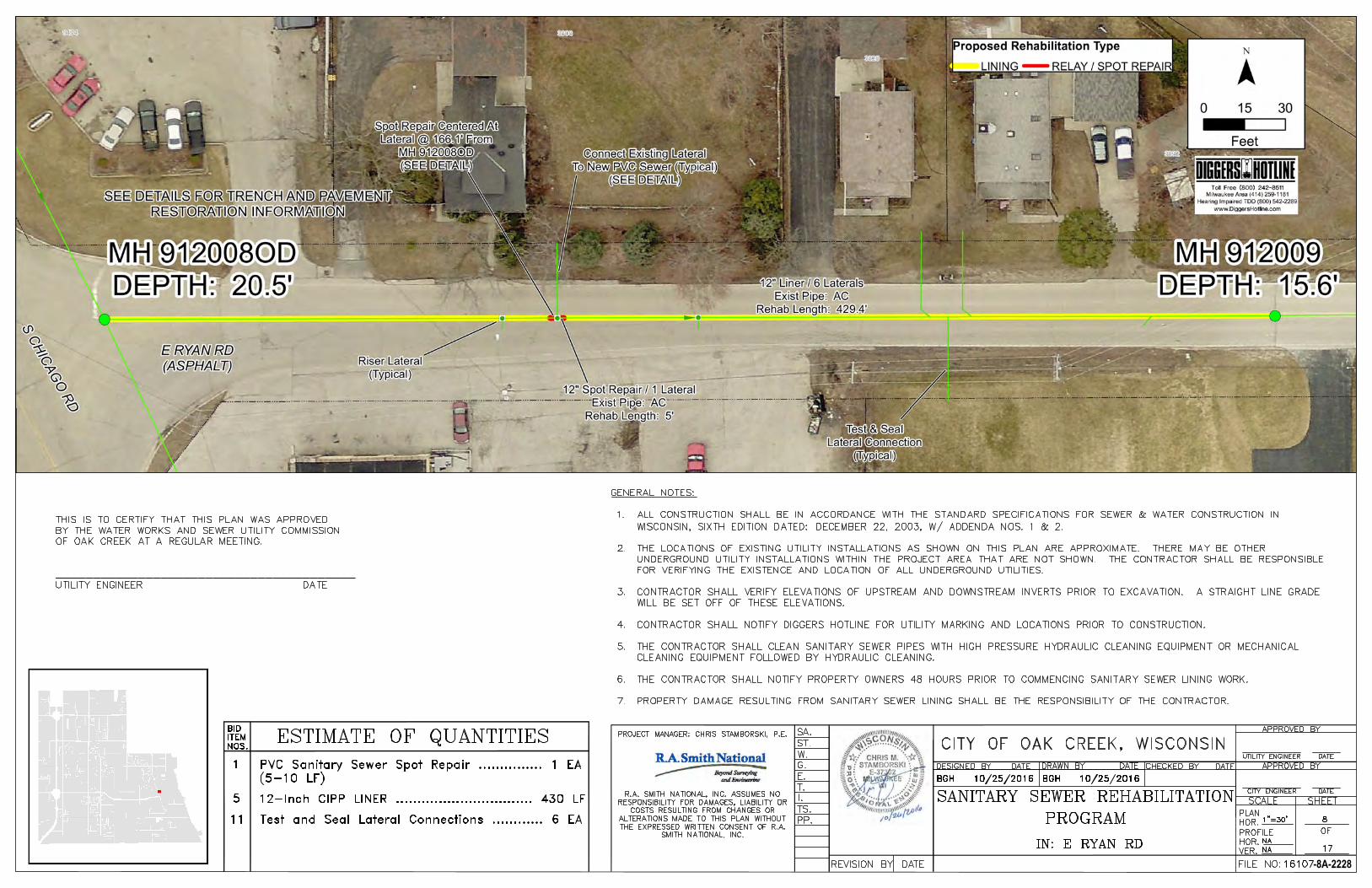
-8A-2228
AutoCAD SHX Text
FILE NO:
AutoCAD SHX Text
OF
AutoCAD SHX Text
VER.
AutoCAD SHX Text
HOR.
AutoCAD SHX Text
PROFILE
AutoCAD SHX Text
HOR.
AutoCAD SHX Text
PLAN
AutoCAD SHX Text
DATE
AutoCAD SHX Text
CITY ENGINEER
AutoCAD SHX Text
SHEET
AutoCAD SHX Text
SCALE
AutoCAD SHX Text
APPROVED BY
AutoCAD SHX Text
DATE
AutoCAD SHX Text
CHECKED BY
AutoCAD SHX Text
DATE
AutoCAD SHX Text
DRAWN BY
AutoCAD SHX Text
DATE
AutoCAD SHX Text
DESIGNED BY
AutoCAD SHX Text
DATE
AutoCAD SHX Text
REVISION BY
AutoCAD SHX Text
PP.
AutoCAD SHX Text
TS.
AutoCAD SHX Text
I.
AutoCAD SHX Text
T.
AutoCAD SHX Text
E.
AutoCAD SHX Text
G.
AutoCAD SHX Text
ST.
AutoCAD SHX Text
W.
AutoCAD SHX Text
SA.
AutoCAD SHX Text
CITY OF OAK CREEK, WISCONSIN
AutoCAD SHX Text
SANITARY SEWER REHABILITATION
AutoCAD SHX Text
8
AutoCAD SHX Text
17
AutoCAD SHX Text
1"=30'
AutoCAD SHX Text
BGH 10/25/2016
AutoCAD SHX Text
BGH 10/25/2016
AutoCAD SHX Text
NA
AutoCAD SHX Text
NA
AutoCAD SHX Text
APPROVED BY
AutoCAD SHX Text
UTILITY ENGINEER
AutoCAD SHX Text
DATE
AutoCAD SHX Text
PROGRAM
AutoCAD SHX Text
IN: E RYAN RD
AutoCAD SHX Text
ITEM
AutoCAD SHX Text
BID
AutoCAD SHX Text
NOS.
AutoCAD SHX Text
ESTIMATE OF QUANTITIES
AutoCAD SHX Text
GENERAL NOTES: 1.ALL CONSTRUCTION SHALL BE IN ACCORDANCE WITH THE STANDARD SPECIFICATIONS FOR SEWER & WATER CONSTRUCTION IN ALL CONSTRUCTION SHALL BE IN ACCORDANCE WITH THE STANDARD SPECIFICATIONS FOR SEWER & WATER CONSTRUCTION IN WISCONSIN, SIXTH EDITION DATED: DECEMBER 22, 2003, W/ ADDENDA NOS. 1 & 2. 2.THE LOCATIONS OF EXISTING UTILITY INSTALLATIONS AS SHOWN ON THIS PLAN ARE APPROXIMATE. THERE MAY BE OTHER THE LOCATIONS OF EXISTING UTILITY INSTALLATIONS AS SHOWN ON THIS PLAN ARE APPROXIMATE. THERE MAY BE OTHER UNDERGROUND UTILITY INSTALLATIONS WITHIN THE PROJECT AREA THAT ARE NOT SHOWN. THE CONTRACTOR SHALL BE RESPONSIBLE FOR VERIFYING THE EXISTENCE AND LOCATION OF ALL UNDERGROUND UTILITIES. 3.CONTRACTOR SHALL VERIFY ELEVATIONS OF UPSTREAM AND DOWNSTREAM INVERTS PRIOR TO EXCAVATION. A STRAIGHT LINE GRADE CONTRACTOR SHALL VERIFY ELEVATIONS OF UPSTREAM AND DOWNSTREAM INVERTS PRIOR TO EXCAVATION. A STRAIGHT LINE GRADE WILL BE SET OFF OF THESE ELEVATIONS. 4.CONTRACTOR SHALL NOTIFY DIGGERS HOTLINE FOR UTILITY MARKING AND LOCATIONS PRIOR TO CONSTRUCTION. CONTRACTOR SHALL NOTIFY DIGGERS HOTLINE FOR UTILITY MARKING AND LOCATIONS PRIOR TO CONSTRUCTION. 5.THE CONTRACTOR SHALL CLEAN SANITARY SEWER PIPES WITH HIGH PRESSURE HYDRAULIC CLEANING EQUIPMENT OR MECHANICAL THE CONTRACTOR SHALL CLEAN SANITARY SEWER PIPES WITH HIGH PRESSURE HYDRAULIC CLEANING EQUIPMENT OR MECHANICAL CLEANING EQUIPMENT FOLLOWED BY HYDRAULIC CLEANING. 6.THE CONTRACTOR SHALL NOTIFY PROPERTY OWNERS 48 HOURS PRIOR TO COMMENCING SANITARY SEWER LINING WORK. THE CONTRACTOR SHALL NOTIFY PROPERTY OWNERS 48 HOURS PRIOR TO COMMENCING SANITARY SEWER LINING WORK. 7.PROPERTY DAMAGE RESULTING FROM SANITARY SEWER LINING SHALL BE THE RESPONSIBILITY OF THE CONTRACTOR.PROPERTY DAMAGE RESULTING FROM SANITARY SEWER LINING SHALL BE THE RESPONSIBILITY OF THE CONTRACTOR.
AutoCAD SHX Text
THIS IS TO CERTIFY THAT THIS PLAN WAS APPROVED BY THE WATER WORKS AND SEWER UTILITY COMMISSION OF OAK CREEK AT A REGULAR MEETING. ________________________________________ UTILITY ENGINEER DATE
AutoCAD SHX Text
PROJECT MANAGER: CHRIS STAMBORSKI, P.E.
AutoCAD SHX Text
R.A. SMITH NATIONAL, INC. ASSUMES NO RESPONSIBILITY FOR DAMAGES, LIABILITY OR COSTS RESULTING FROM CHANGES OR ALTERATIONS MADE TO THIS PLAN WITHOUT THE EXPRESSED WRITTEN CONSENT OF R.A. SMITH NATIONAL, INC.
AutoCAD SHX Text
16107
AutoCAD SHX Text
5
AutoCAD SHX Text
12-Inch CIPP LINER ................................ 430 LF
AutoCAD SHX Text
1
AutoCAD SHX Text
PVC Sanitary Sewer Spot Repair ............... 1 EA
AutoCAD SHX Text
11
AutoCAD SHX Text
Test and Seal Lateral Connections ............ 6 EA
AutoCAD SHX Text
(5-10 LF)

-9A-2229
AutoCAD SHX Text
FILE NO:
AutoCAD SHX Text
OF
AutoCAD SHX Text
VER.
AutoCAD SHX Text
HOR.
AutoCAD SHX Text
PROFILE
AutoCAD SHX Text
HOR.
AutoCAD SHX Text
PLAN
AutoCAD SHX Text
DATE
AutoCAD SHX Text
CITY ENGINEER
AutoCAD SHX Text
SHEET
AutoCAD SHX Text
SCALE
AutoCAD SHX Text
APPROVED BY
AutoCAD SHX Text
DATE
AutoCAD SHX Text
CHECKED BY
AutoCAD SHX Text
DATE
AutoCAD SHX Text
DRAWN BY
AutoCAD SHX Text
DATE
AutoCAD SHX Text
DESIGNED BY
AutoCAD SHX Text
DATE
AutoCAD SHX Text
REVISION BY
AutoCAD SHX Text
PP.
AutoCAD SHX Text
TS.
AutoCAD SHX Text
I.
AutoCAD SHX Text
T.
AutoCAD SHX Text
E.
AutoCAD SHX Text
G.
AutoCAD SHX Text
ST.
AutoCAD SHX Text
W.
AutoCAD SHX Text
SA.
AutoCAD SHX Text
CITY OF OAK CREEK, WISCONSIN
AutoCAD SHX Text
SANITARY SEWER REHABILITATION
AutoCAD SHX Text
9
AutoCAD SHX Text
17
AutoCAD SHX Text
1"=20'
AutoCAD SHX Text
BGH 10/25/2016
AutoCAD SHX Text
BGH 10/25/2016
AutoCAD SHX Text
NA
AutoCAD SHX Text
NA
AutoCAD SHX Text
APPROVED BY
AutoCAD SHX Text
UTILITY ENGINEER
AutoCAD SHX Text
DATE
AutoCAD SHX Text
PROGRAM
AutoCAD SHX Text
IN: E GARDEN PL
AutoCAD SHX Text
ITEM
AutoCAD SHX Text
BID
AutoCAD SHX Text
NOS.
AutoCAD SHX Text
ESTIMATE OF QUANTITIES
AutoCAD SHX Text
THIS IS TO CERTIFY THAT THIS PLAN WAS APPROVED BY THE WATER WORKS AND SEWER UTILITY COMMISSION OF OAK CREEK AT A REGULAR MEETING. ________________________________________ UTILITY ENGINEER DATE
AutoCAD SHX Text
PROJECT MANAGER: CHRIS STAMBORSKI, P.E.
AutoCAD SHX Text
R.A. SMITH NATIONAL, INC. ASSUMES NO RESPONSIBILITY FOR DAMAGES, LIABILITY OR COSTS RESULTING FROM CHANGES OR ALTERATIONS MADE TO THIS PLAN WITHOUT THE EXPRESSED WRITTEN CONSENT OF R.A. SMITH NATIONAL, INC.
AutoCAD SHX Text
16107
AutoCAD SHX Text
GENERAL NOTES: 1.THE CONTRACTOR SHALL CLEAN THE CONTRACTOR SHALL CLEAN SANITARY SEWER PIPES WITH HIGH PRESSURE HYDRAULIC CLEANING EQUIPMENT FOLLOWED BY HYDRAULIC CLEANING. 2.THE CONTRACTOR SHALL NOTIFY THE CONTRACTOR SHALL NOTIFY PROPERTY OWNERS 48 HOURS PRIOR TO COMMENCING SANITARY SEWER LINING WORK. 3.PROPERTY DAMAGE RESULTING FROM PROPERTY DAMAGE RESULTING FROM SANITARY SEWER LINING SHALL BE THE RESPONSIBILITY OF THE CONTRACTOR.
AutoCAD SHX Text
4
AutoCAD SHX Text
8-Inch CIPP Liner ................................... 37 LF

-10A-2230
AutoCAD SHX Text
FILE NO:
AutoCAD SHX Text
OF
AutoCAD SHX Text
VER.
AutoCAD SHX Text
HOR.
AutoCAD SHX Text
PROFILE
AutoCAD SHX Text
HOR.
AutoCAD SHX Text
PLAN
AutoCAD SHX Text
DATE
AutoCAD SHX Text
CITY ENGINEER
AutoCAD SHX Text
SHEET
AutoCAD SHX Text
SCALE
AutoCAD SHX Text
APPROVED BY
AutoCAD SHX Text
DATE
AutoCAD SHX Text
CHECKED BY
AutoCAD SHX Text
DATE
AutoCAD SHX Text
DRAWN BY
AutoCAD SHX Text
DATE
AutoCAD SHX Text
DESIGNED BY
AutoCAD SHX Text
DATE
AutoCAD SHX Text
REVISION BY
AutoCAD SHX Text
PP.
AutoCAD SHX Text
TS.
AutoCAD SHX Text
I.
AutoCAD SHX Text
T.
AutoCAD SHX Text
E.
AutoCAD SHX Text
G.
AutoCAD SHX Text
ST.
AutoCAD SHX Text
W.
AutoCAD SHX Text
SA.
AutoCAD SHX Text
CITY OF OAK CREEK, WISCONSIN
AutoCAD SHX Text
SANITARY SEWER REHABILITATION
AutoCAD SHX Text
10
AutoCAD SHX Text
17
AutoCAD SHX Text
1"=150'
AutoCAD SHX Text
BGH 10/25/2016
AutoCAD SHX Text
BGH 10/25/2016
AutoCAD SHX Text
NA
AutoCAD SHX Text
NA
AutoCAD SHX Text
APPROVED BY
AutoCAD SHX Text
UTILITY ENGINEER
AutoCAD SHX Text
DATE
AutoCAD SHX Text
PROGRAM
AutoCAD SHX Text
IN: S NICHOLSON RD
AutoCAD SHX Text
ITEM
AutoCAD SHX Text
BID
AutoCAD SHX Text
NOS.
AutoCAD SHX Text
ESTIMATE OF QUANTITIES
AutoCAD SHX Text
THIS IS TO CERTIFY THAT THIS PLAN WAS APPROVED BY THE WATER WORKS AND SEWER UTILITY COMMISSION OF OAK CREEK AT A REGULAR MEETING. ________________________________________ UTILITY ENGINEER DATE
AutoCAD SHX Text
PROJECT MANAGER: CHRIS STAMBORSKI, P.E.
AutoCAD SHX Text
R.A. SMITH NATIONAL, INC. ASSUMES NO RESPONSIBILITY FOR DAMAGES, LIABILITY OR COSTS RESULTING FROM CHANGES OR ALTERATIONS MADE TO THIS PLAN WITHOUT THE EXPRESSED WRITTEN CONSENT OF R.A. SMITH NATIONAL, INC.
AutoCAD SHX Text
16107
AutoCAD SHX Text
GENERAL NOTES: 1.THE CONTRACTOR SHALL CLEAN SANITARY SEWER PIPES WITH HIGH THE CONTRACTOR SHALL CLEAN SANITARY SEWER PIPES WITH HIGH PRESSURE HYDRAULIC CLEANING EQUIPMENT FOLLOWED BY HYDRAULIC CLEANING. 2.THE CONTRACTOR SHALL NOTIFY PROPERTY OWNERS 48 HOURS PRIOR THE CONTRACTOR SHALL NOTIFY PROPERTY OWNERS 48 HOURS PRIOR TO COMMENCING SANITARY SEWER LINING WORK. 3.PROPERTY DAMAGE RESULTING FROM SANITARY SEWER LINING SHALL PROPERTY DAMAGE RESULTING FROM SANITARY SEWER LINING SHALL BE THE RESPONSIBILITY OF THE CONTRACTOR.
AutoCAD SHX Text
7
AutoCAD SHX Text
18-Inch CIPP Liner ................................ 114 LF
AutoCAD SHX Text
8
AutoCAD SHX Text
21-Inch CIPP Liner ................................ 829 LF
AutoCAD SHX Text
11
AutoCAD SHX Text
Test and Seal Lateral Connections ............ 6 EA
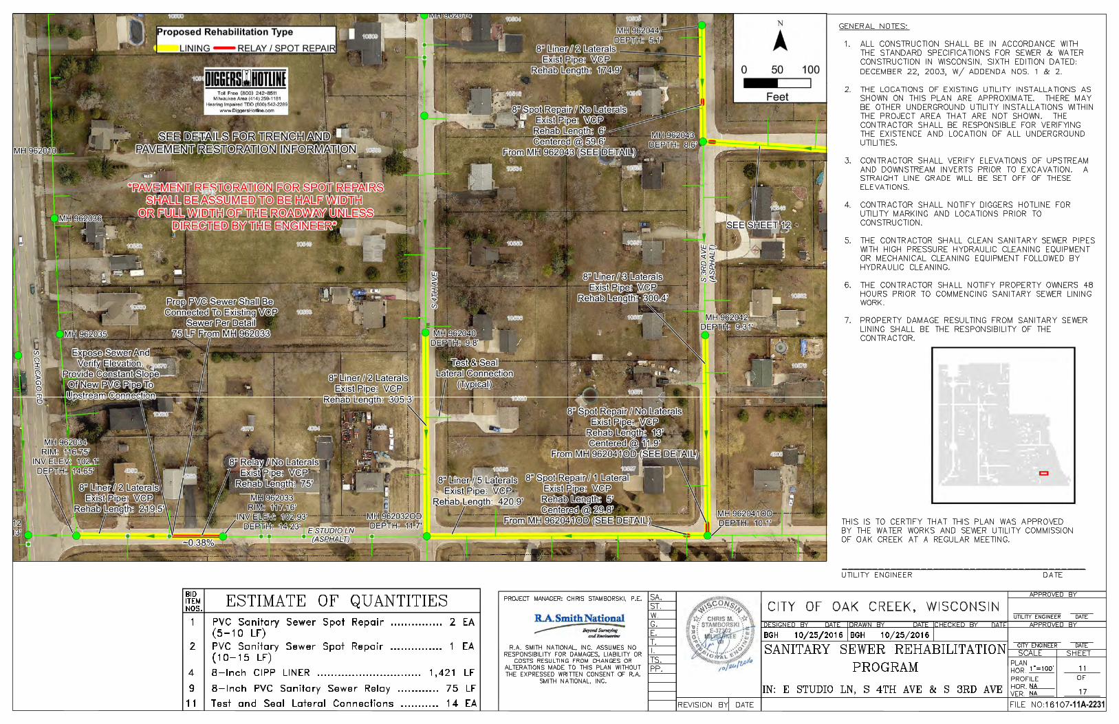
-11A-2231
AutoCAD SHX Text
FILE NO:
AutoCAD SHX Text
OF
AutoCAD SHX Text
VER.
AutoCAD SHX Text
HOR.
AutoCAD SHX Text
PROFILE
AutoCAD SHX Text
HOR.
AutoCAD SHX Text
PLAN
AutoCAD SHX Text
DATE
AutoCAD SHX Text
CITY ENGINEER
AutoCAD SHX Text
SHEET
AutoCAD SHX Text
SCALE
AutoCAD SHX Text
APPROVED BY
AutoCAD SHX Text
DATE
AutoCAD SHX Text
CHECKED BY
AutoCAD SHX Text
DATE
AutoCAD SHX Text
DRAWN BY
AutoCAD SHX Text
DATE
AutoCAD SHX Text
DESIGNED BY
AutoCAD SHX Text
DATE
AutoCAD SHX Text
REVISION BY
AutoCAD SHX Text
PP.
AutoCAD SHX Text
TS.
AutoCAD SHX Text
I.
AutoCAD SHX Text
T.
AutoCAD SHX Text
E.
AutoCAD SHX Text
G.
AutoCAD SHX Text
ST.
AutoCAD SHX Text
W.
AutoCAD SHX Text
SA.
AutoCAD SHX Text
CITY OF OAK CREEK, WISCONSIN
AutoCAD SHX Text
SANITARY SEWER REHABILITATION
AutoCAD SHX Text
11
AutoCAD SHX Text
17
AutoCAD SHX Text
1"=100'
AutoCAD SHX Text
BGH 10/25/2016
AutoCAD SHX Text
BGH 10/25/2016
AutoCAD SHX Text
NA
AutoCAD SHX Text
NA
AutoCAD SHX Text
APPROVED BY
AutoCAD SHX Text
UTILITY ENGINEER
AutoCAD SHX Text
DATE
AutoCAD SHX Text
PROGRAM
AutoCAD SHX Text
IN: E STUDIO LN, S 4TH AVE & S 3RD AVE
AutoCAD SHX Text
ITEM
AutoCAD SHX Text
BID
AutoCAD SHX Text
NOS.
AutoCAD SHX Text
ESTIMATE OF QUANTITIES
AutoCAD SHX Text
1
AutoCAD SHX Text
PVC Sanitary Sewer Spot Repair ............... 2 EA
AutoCAD SHX Text
GENERAL NOTES: 1.ALL CONSTRUCTION SHALL BE IN ACCORDANCE WITH ALL CONSTRUCTION SHALL BE IN ACCORDANCE WITH THE STANDARD SPECIFICATIONS FOR SEWER & WATER CONSTRUCTION IN WISCONSIN, SIXTH EDITION DATED: DECEMBER 22, 2003, W/ ADDENDA NOS. 1 & 2. 2.THE LOCATIONS OF EXISTING UTILITY INSTALLATIONS AS THE LOCATIONS OF EXISTING UTILITY INSTALLATIONS AS SHOWN ON THIS PLAN ARE APPROXIMATE. THERE MAY BE OTHER UNDERGROUND UTILITY INSTALLATIONS WITHIN THE PROJECT AREA THAT ARE NOT SHOWN. THE CONTRACTOR SHALL BE RESPONSIBLE FOR VERIFYING THE EXISTENCE AND LOCATION OF ALL UNDERGROUND UTILITIES. 3.CONTRACTOR SHALL VERIFY ELEVATIONS OF UPSTREAM CONTRACTOR SHALL VERIFY ELEVATIONS OF UPSTREAM AND DOWNSTREAM INVERTS PRIOR TO EXCAVATION. A STRAIGHT LINE GRADE WILL BE SET OFF OF THESE ELEVATIONS. 4.CONTRACTOR SHALL NOTIFY DIGGERS HOTLINE FOR CONTRACTOR SHALL NOTIFY DIGGERS HOTLINE FOR UTILITY MARKING AND LOCATIONS PRIOR TO CONSTRUCTION. 5.THE CONTRACTOR SHALL CLEAN SANITARY SEWER PIPES THE CONTRACTOR SHALL CLEAN SANITARY SEWER PIPES WITH HIGH PRESSURE HYDRAULIC CLEANING EQUIPMENT OR MECHANICAL CLEANING EQUIPMENT FOLLOWED BY HYDRAULIC CLEANING. 6.THE CONTRACTOR SHALL NOTIFY PROPERTY OWNERS 48 THE CONTRACTOR SHALL NOTIFY PROPERTY OWNERS 48 HOURS PRIOR TO COMMENCING SANITARY SEWER LINING WORK. 7.PROPERTY DAMAGE RESULTING FROM SANITARY SEWER PROPERTY DAMAGE RESULTING FROM SANITARY SEWER LINING SHALL BE THE RESPONSIBILITY OF THE CONTRACTOR.
AutoCAD SHX Text
THIS IS TO CERTIFY THAT THIS PLAN WAS APPROVED BY THE WATER WORKS AND SEWER UTILITY COMMISSION OF OAK CREEK AT A REGULAR MEETING. ________________________________________ UTILITY ENGINEER DATE
AutoCAD SHX Text
PROJECT MANAGER: CHRIS STAMBORSKI, P.E.
AutoCAD SHX Text
R.A. SMITH NATIONAL, INC. ASSUMES NO RESPONSIBILITY FOR DAMAGES, LIABILITY OR COSTS RESULTING FROM CHANGES OR ALTERATIONS MADE TO THIS PLAN WITHOUT THE EXPRESSED WRITTEN CONSENT OF R.A. SMITH NATIONAL, INC.
AutoCAD SHX Text
16107
AutoCAD SHX Text
4
AutoCAD SHX Text
8-Inch CIPP LINER .............................. 1,421 LF
AutoCAD SHX Text
9
AutoCAD SHX Text
8-Inch PVC Sanitary Sewer Relay ............ 75 LF
AutoCAD SHX Text
11
AutoCAD SHX Text
Test and Seal Lateral Connections ........... 14 EA
AutoCAD SHX Text
(5-10 LF)
AutoCAD SHX Text
2
AutoCAD SHX Text
PVC Sanitary Sewer Spot Repair ............... 1 EA
AutoCAD SHX Text
(10-15 LF)

-11A-2231
-12A-2232
AutoCAD SHX Text
FILE NO:
AutoCAD SHX Text
OF
AutoCAD SHX Text
VER.
AutoCAD SHX Text
HOR.
AutoCAD SHX Text
PROFILE
AutoCAD SHX Text
HOR.
AutoCAD SHX Text
PLAN
AutoCAD SHX Text
DATE
AutoCAD SHX Text
CITY ENGINEER
AutoCAD SHX Text
SHEET
AutoCAD SHX Text
SCALE
AutoCAD SHX Text
APPROVED BY
AutoCAD SHX Text
DATE
AutoCAD SHX Text
CHECKED BY
AutoCAD SHX Text
DATE
AutoCAD SHX Text
DRAWN BY
AutoCAD SHX Text
DATE
AutoCAD SHX Text
DESIGNED BY
AutoCAD SHX Text
DATE
AutoCAD SHX Text
REVISION BY
AutoCAD SHX Text
PP.
AutoCAD SHX Text
TS.
AutoCAD SHX Text
I.
AutoCAD SHX Text
T.
AutoCAD SHX Text
E.
AutoCAD SHX Text
G.
AutoCAD SHX Text
ST.
AutoCAD SHX Text
W.
AutoCAD SHX Text
SA.
AutoCAD SHX Text
CITY OF OAK CREEK, WISCONSIN
AutoCAD SHX Text
SANITARY SEWER REHABILITATION
AutoCAD SHX Text
12
AutoCAD SHX Text
17
AutoCAD SHX Text
1"=80'
AutoCAD SHX Text
BGH 10/25/2016
AutoCAD SHX Text
BGH 10/25/2016
AutoCAD SHX Text
NA
AutoCAD SHX Text
NA
AutoCAD SHX Text
APPROVED BY
AutoCAD SHX Text
UTILITY ENGINEER
AutoCAD SHX Text
DATE
AutoCAD SHX Text
PROGRAM
AutoCAD SHX Text
IN: E ALTON RD & S ALTON RD
AutoCAD SHX Text
ITEM
AutoCAD SHX Text
BID
AutoCAD SHX Text
NOS.
AutoCAD SHX Text
ESTIMATE OF QUANTITIES
AutoCAD SHX Text
1
AutoCAD SHX Text
PVC Sanitary Sewer Spot Repair ............... 3 EA
AutoCAD SHX Text
GENERAL NOTES: 1.ALL CONSTRUCTION SHALL BE IN ACCORDANCE WITH ALL CONSTRUCTION SHALL BE IN ACCORDANCE WITH THE STANDARD SPECIFICATIONS FOR SEWER & WATER CONSTRUCTION IN WISCONSIN, SIXTH EDITION DATED: DECEMBER 22, 2003, W/ ADDENDA NOS. 1 & 2. 2.THE LOCATIONS OF EXISTING UTILITY INSTALLATIONS AS THE LOCATIONS OF EXISTING UTILITY INSTALLATIONS AS SHOWN ON THIS PLAN ARE APPROXIMATE. THERE MAY BE OTHER UNDERGROUND UTILITY INSTALLATIONS WITHIN THE PROJECT AREA THAT ARE NOT SHOWN. THE CONTRACTOR SHALL BE RESPONSIBLE FOR VERIFYING THE EXISTENCE AND LOCATION OF ALL UNDERGROUND UTILITIES. 3.CONTRACTOR SHALL VERIFY ELEVATIONS OF UPSTREAM CONTRACTOR SHALL VERIFY ELEVATIONS OF UPSTREAM AND DOWNSTREAM INVERTS PRIOR TO EXCAVATION. A STRAIGHT LINE GRADE WILL BE SET OFF OF THESE ELEVATIONS. 4.CONTRACTOR SHALL NOTIFY DIGGERS HOTLINE FOR CONTRACTOR SHALL NOTIFY DIGGERS HOTLINE FOR UTILITY MARKING AND LOCATIONS PRIOR TO CONSTRUCTION. 5.THE CONTRACTOR SHALL CLEAN SANITARY SEWER PIPES THE CONTRACTOR SHALL CLEAN SANITARY SEWER PIPES WITH HIGH PRESSURE HYDRAULIC CLEANING EQUIPMENT OR MECHANICAL CLEANING EQUIPMENT FOLLOWED BY HYDRAULIC CLEANING. 6.THE CONTRACTOR SHALL NOTIFY PROPERTY OWNERS 48 THE CONTRACTOR SHALL NOTIFY PROPERTY OWNERS 48 HOURS PRIOR TO COMMENCING SANITARY SEWER LINING WORK. 7.PROPERTY DAMAGE RESULTING FROM SANITARY SEWER PROPERTY DAMAGE RESULTING FROM SANITARY SEWER LINING SHALL BE THE RESPONSIBILITY OF THE CONTRACTOR.
AutoCAD SHX Text
THIS IS TO CERTIFY THAT THIS PLAN WAS APPROVED BY THE WATER WORKS AND SEWER UTILITY COMMISSION OF OAK CREEK AT A REGULAR MEETING. ________________________________________ UTILITY ENGINEER DATE
AutoCAD SHX Text
PROJECT MANAGER: CHRIS STAMBORSKI, P.E.
AutoCAD SHX Text
R.A. SMITH NATIONAL, INC. ASSUMES NO RESPONSIBILITY FOR DAMAGES, LIABILITY OR COSTS RESULTING FROM CHANGES OR ALTERATIONS MADE TO THIS PLAN WITHOUT THE EXPRESSED WRITTEN CONSENT OF R.A. SMITH NATIONAL, INC.
AutoCAD SHX Text
16107
AutoCAD SHX Text
4
AutoCAD SHX Text
8-Inch CIPP LINER ................................. 856 LF
AutoCAD SHX Text
9
AutoCAD SHX Text
8-Inch PVC Sanitary Sewer Relay ............ 19 LF
AutoCAD SHX Text
11
AutoCAD SHX Text
Test and Seal Lateral Connections ........... 10 EA
AutoCAD SHX Text
(5-10 LF)

-13A-2233
AutoCAD SHX Text
FILE NO:
AutoCAD SHX Text
OF
AutoCAD SHX Text
VER.
AutoCAD SHX Text
HOR.
AutoCAD SHX Text
PROFILE
AutoCAD SHX Text
HOR.
AutoCAD SHX Text
PLAN
AutoCAD SHX Text
DATE
AutoCAD SHX Text
CITY ENGINEER
AutoCAD SHX Text
SHEET
AutoCAD SHX Text
SCALE
AutoCAD SHX Text
APPROVED BY
AutoCAD SHX Text
DATE
AutoCAD SHX Text
CHECKED BY
AutoCAD SHX Text
DATE
AutoCAD SHX Text
DRAWN BY
AutoCAD SHX Text
DATE
AutoCAD SHX Text
DESIGNED BY
AutoCAD SHX Text
DATE
AutoCAD SHX Text
REVISION BY
AutoCAD SHX Text
PP.
AutoCAD SHX Text
TS.
AutoCAD SHX Text
I.
AutoCAD SHX Text
T.
AutoCAD SHX Text
E.
AutoCAD SHX Text
G.
AutoCAD SHX Text
ST.
AutoCAD SHX Text
W.
AutoCAD SHX Text
SA.
AutoCAD SHX Text
CITY OF OAK CREEK, WISCONSIN
AutoCAD SHX Text
SANITARY SEWER REHABILITATION
AutoCAD SHX Text
13
AutoCAD SHX Text
17
AutoCAD SHX Text
1"=80'
AutoCAD SHX Text
BGH 10/25/2016
AutoCAD SHX Text
BGH 10/25/2016
AutoCAD SHX Text
NA
AutoCAD SHX Text
NA
AutoCAD SHX Text
APPROVED BY
AutoCAD SHX Text
UTILITY ENGINEER
AutoCAD SHX Text
DATE
AutoCAD SHX Text
PROGRAM
AutoCAD SHX Text
IN: E STUDIO LN, S BARTON RD, & E ELM RD
AutoCAD SHX Text
ITEM
AutoCAD SHX Text
BID
AutoCAD SHX Text
NOS.
AutoCAD SHX Text
ESTIMATE OF QUANTITIES
AutoCAD SHX Text
GENERAL NOTES: 1.ALL CONSTRUCTION SHALL BE IN ACCORDANCE WITH THE STANDARD SPECIFICATIONS ALL CONSTRUCTION SHALL BE IN ACCORDANCE WITH THE STANDARD SPECIFICATIONS FOR SEWER & WATER CONSTRUCTION IN WISCONSIN, SIXTH EDITION DATED: DECEMBER 22, 2003, W/ ADDENDA NOS. 1 & 2. 2.THE LOCATIONS OF EXISTING UTILITY INSTALLATIONS AS SHOWN ON THIS PLAN ARE THE LOCATIONS OF EXISTING UTILITY INSTALLATIONS AS SHOWN ON THIS PLAN ARE APPROXIMATE. THERE MAY BE OTHER UNDERGROUND UTILITY INSTALLATIONS WITHIN THE PROJECT AREA THAT ARE NOT SHOWN. THE CONTRACTOR SHALL BE RESPONSIBLE FOR VERIFYING THE EXISTENCE AND LOCATION OF ALL UNDERGROUND UTILITIES. 3.CONTRACTOR SHALL VERIFY ELEVATIONS OF UPSTREAM AND DOWNSTREAM INVERTS CONTRACTOR SHALL VERIFY ELEVATIONS OF UPSTREAM AND DOWNSTREAM INVERTS PRIOR TO EXCAVATION. A STRAIGHT LINE GRADE WILL BE SET OFF OF THESE ELEVATIONS. 4.CONTRACTOR SHALL NOTIFY DIGGERS HOTLINE FOR UTILITY MARKING AND LOCATIONS CONTRACTOR SHALL NOTIFY DIGGERS HOTLINE FOR UTILITY MARKING AND LOCATIONS PRIOR TO CONSTRUCTION. 5.THE CONTRACTOR SHALL CLEAN SANITARY SEWER PIPES WITH HIGH PRESSURE THE CONTRACTOR SHALL CLEAN SANITARY SEWER PIPES WITH HIGH PRESSURE HYDRAULIC CLEANING EQUIPMENT OR MECHANICAL CLEANING EQUIPMENT FOLLOWED BY HYDRAULIC CLEANING. 6.THE CONTRACTOR SHALL NOTIFY PROPERTY OWNERS 48 HOURS PRIOR TO COMMENCING THE CONTRACTOR SHALL NOTIFY PROPERTY OWNERS 48 HOURS PRIOR TO COMMENCING SANITARY SEWER LINING WORK. 7.PROPERTY DAMAGE RESULTING FROM SANITARY SEWER LINING SHALL BE THE PROPERTY DAMAGE RESULTING FROM SANITARY SEWER LINING SHALL BE THE RESPONSIBILITY OF THE CONTRACTOR.
AutoCAD SHX Text
THIS IS TO CERTIFY THAT THIS PLAN WAS APPROVED BY THE WATER WORKS AND SEWER UTILITY COMMISSION OF OAK CREEK AT A REGULAR MEETING. ________________________________________ UTILITY ENGINEER DATE
AutoCAD SHX Text
PROJECT MANAGER: CHRIS STAMBORSKI, P.E.
AutoCAD SHX Text
R.A. SMITH NATIONAL, INC. ASSUMES NO RESPONSIBILITY FOR DAMAGES, LIABILITY OR COSTS RESULTING FROM CHANGES OR ALTERATIONS MADE TO THIS PLAN WITHOUT THE EXPRESSED WRITTEN CONSENT OF R.A. SMITH NATIONAL, INC.
AutoCAD SHX Text
16107
AutoCAD SHX Text
4
AutoCAD SHX Text
8-Inch CIPP LINER ................................. 678 LF
AutoCAD SHX Text
9
AutoCAD SHX Text
8-Inch PVC Sanitary Sewer Relay ............ 50 LF
AutoCAD SHX Text
11
AutoCAD SHX Text
Test and Seal Lateral Connections ............ 7 EA
AutoCAD SHX Text
(EASEMENT)
AutoCAD SHX Text
5
AutoCAD SHX Text
12-Inch CIPP LINER ................................ 161 LF
AutoCAD SHX Text
6
AutoCAD SHX Text
15-Inch CIPP LINER ................................ 250 LF

-14A-2234
AutoCAD SHX Text
FILE NO:
AutoCAD SHX Text
OF
AutoCAD SHX Text
VER.
AutoCAD SHX Text
HOR.
AutoCAD SHX Text
PROFILE
AutoCAD SHX Text
HOR.
AutoCAD SHX Text
PLAN
AutoCAD SHX Text
DATE
AutoCAD SHX Text
CITY ENGINEER
AutoCAD SHX Text
SHEET
AutoCAD SHX Text
SCALE
AutoCAD SHX Text
APPROVED BY
AutoCAD SHX Text
DATE
AutoCAD SHX Text
CHECKED BY
AutoCAD SHX Text
DATE
AutoCAD SHX Text
DRAWN BY
AutoCAD SHX Text
DATE
AutoCAD SHX Text
DESIGNED BY
AutoCAD SHX Text
DATE
AutoCAD SHX Text
REVISION BY
AutoCAD SHX Text
PP.
AutoCAD SHX Text
TS.
AutoCAD SHX Text
I.
AutoCAD SHX Text
T.
AutoCAD SHX Text
E.
AutoCAD SHX Text
G.
AutoCAD SHX Text
ST.
AutoCAD SHX Text
W.
AutoCAD SHX Text
SA.
AutoCAD SHX Text
CITY OF OAK CREEK, WISCONSIN
AutoCAD SHX Text
SANITARY SEWER REHABILITATION
AutoCAD SHX Text
14
AutoCAD SHX Text
17
AutoCAD SHX Text
1"=30'
AutoCAD SHX Text
BGH 10/25/2016
AutoCAD SHX Text
BGH 10/25/2016
AutoCAD SHX Text
NA
AutoCAD SHX Text
NA
AutoCAD SHX Text
APPROVED BY
AutoCAD SHX Text
UTILITY ENGINEER
AutoCAD SHX Text
DATE
AutoCAD SHX Text
PROGRAM
AutoCAD SHX Text
IN: EASEMENT
AutoCAD SHX Text
ITEM
AutoCAD SHX Text
BID
AutoCAD SHX Text
NOS.
AutoCAD SHX Text
ESTIMATE OF QUANTITIES
AutoCAD SHX Text
4
AutoCAD SHX Text
8-Inch CIPP Liner .............................. 399 LF
AutoCAD SHX Text
THIS IS TO CERTIFY THAT THIS PLAN WAS APPROVED BY THE WATER WORKS AND SEWER UTILITY COMMISSION OF OAK CREEK AT A REGULAR MEETING. ________________________________________ UTILITY ENGINEER DATE
AutoCAD SHX Text
PROJECT MANAGER: CHRIS STAMBORSKI, P.E.
AutoCAD SHX Text
R.A. SMITH NATIONAL, INC. ASSUMES NO RESPONSIBILITY FOR DAMAGES, LIABILITY OR COSTS RESULTING FROM CHANGES OR ALTERATIONS MADE TO THIS PLAN WITHOUT THE EXPRESSED WRITTEN CONSENT OF R.A. SMITH NATIONAL, INC.
AutoCAD SHX Text
16107
AutoCAD SHX Text
11
AutoCAD SHX Text
Test and Seal Lateral Connections ....... 1 EA
AutoCAD SHX Text
GENERAL NOTES: 1.THE CONTRACTOR SHALL CLEAN SANITARY SEWER PIPES WITH HIGH PRESSURE HYDRAULIC CLEANING THE CONTRACTOR SHALL CLEAN SANITARY SEWER PIPES WITH HIGH PRESSURE HYDRAULIC CLEANING EQUIPMENT OR MECHANICAL CLEANING EQUIPMENT FOLLOWED BY HYDRAULIC CLEANING. 2.THE CONTRACTOR SHALL NOTIFY PROPERTY OWNERS 48 HOURS PRIOR TO COMMENCING SANITARY SEWER THE CONTRACTOR SHALL NOTIFY PROPERTY OWNERS 48 HOURS PRIOR TO COMMENCING SANITARY SEWER LINING WORK. 3.PROPERTY DAMAGE RESULTING FROM SANITARY SEWER LINING SHALL BE THE RESPONSIBILITY OF THE PROPERTY DAMAGE RESULTING FROM SANITARY SEWER LINING SHALL BE THE RESPONSIBILITY OF THE CONTRACTOR.

SANITARY SEWER TRENCH
DETAIL
(NON-PAVEMENT AREAS)
SANITARY SEWER TRENCH
DETAIL
(PAVEMENT AREAS)
SANITARY SEWER SPOT REPAIR - TOP VIEW
(NO LATERAL)
-15A-2235
AutoCAD SHX Text
N. T. S.
AutoCAD SHX Text
6" MIN.
AutoCAD SHX Text
DIA.
AutoCAD SHX Text
PIPE
AutoCAD SHX Text
PIPE DIA.
AutoCAD SHX Text
4" MIN.
AutoCAD SHX Text
6" MIN.
AutoCAD SHX Text
6" MIN.
AutoCAD SHX Text
EXISTING GRADE
AutoCAD SHX Text
PROPOSED SANITARY SEWER
AutoCAD SHX Text
N. T. S.
AutoCAD SHX Text
6" MIN.
AutoCAD SHX Text
DIA.
AutoCAD SHX Text
PIPE
AutoCAD SHX Text
PIPE DIA.
AutoCAD SHX Text
4" MIN.
AutoCAD SHX Text
6" MIN.
AutoCAD SHX Text
6" MIN.
AutoCAD SHX Text
EXISTING PAVEMENT
AutoCAD SHX Text
PROPOSED SANITARY SEWER
AutoCAD SHX Text
PAVEMENT SAWING REQUIRED FOR ALL TRENCHES (TYP.)
AutoCAD SHX Text
FILE NO:
AutoCAD SHX Text
OF
AutoCAD SHX Text
VER.
AutoCAD SHX Text
HOR.
AutoCAD SHX Text
PROFILE
AutoCAD SHX Text
HOR.
AutoCAD SHX Text
PLAN
AutoCAD SHX Text
DATE
AutoCAD SHX Text
CITY ENGINEER
AutoCAD SHX Text
SHEET
AutoCAD SHX Text
SCALE
AutoCAD SHX Text
APPROVED BY
AutoCAD SHX Text
DATE
AutoCAD SHX Text
CHECKED BY
AutoCAD SHX Text
DATE
AutoCAD SHX Text
DRAWN BY
AutoCAD SHX Text
DATE
AutoCAD SHX Text
DESIGNED BY
AutoCAD SHX Text
DATE
AutoCAD SHX Text
REVISION BY
AutoCAD SHX Text
PP.
AutoCAD SHX Text
TS.
AutoCAD SHX Text
I.
AutoCAD SHX Text
T.
AutoCAD SHX Text
E.
AutoCAD SHX Text
G.
AutoCAD SHX Text
ST.
AutoCAD SHX Text
W.
AutoCAD SHX Text
SA.
AutoCAD SHX Text
CITY OF OAK CREEK, WISCONSIN
AutoCAD SHX Text
SANITARY SEWER REHABILITATION
AutoCAD SHX Text
15
AutoCAD SHX Text
17
AutoCAD SHX Text
NA
AutoCAD SHX Text
BGH 10/25/2016
AutoCAD SHX Text
BGH 10/25/2016
AutoCAD SHX Text
NA
AutoCAD SHX Text
NA
AutoCAD SHX Text
APPROVED BY
AutoCAD SHX Text
UTILITY ENGINEER
AutoCAD SHX Text
DATE
AutoCAD SHX Text
PROGRAM
AutoCAD SHX Text
STANDARD DETAILS
AutoCAD SHX Text
FLOW
AutoCAD SHX Text
EXISTING SANITARY SEWER
AutoCAD SHX Text
EXISTING SANITARY SEWER
AutoCAD SHX Text
2"X6" HARDWOOD BLOCKING (TYP.)
AutoCAD SHX Text
PIPE CONNECTOR (FERNCO STAINLESS STEEL 5000 SERIES RC OR EQUAL)
AutoCAD SHX Text
1' MIN. (TYP.)
AutoCAD SHX Text
1' MIN. (TYP.)
AutoCAD SHX Text
1' MIN. (TYP.)
AutoCAD SHX Text
N. T. S.
AutoCAD SHX Text
PROJECT MANAGER: CHRIS STAMBORSKI, P.E.
AutoCAD SHX Text
R.A. SMITH NATIONAL, INC. ASSUMES NO RESPONSIBILITY FOR DAMAGES, LIABILITY OR COSTS RESULTING FROM CHANGES OR ALTERATIONS MADE TO THIS PLAN WITHOUT THE EXPRESSED WRITTEN CONSENT OF R.A. SMITH NATIONAL, INC.
AutoCAD SHX Text
16107
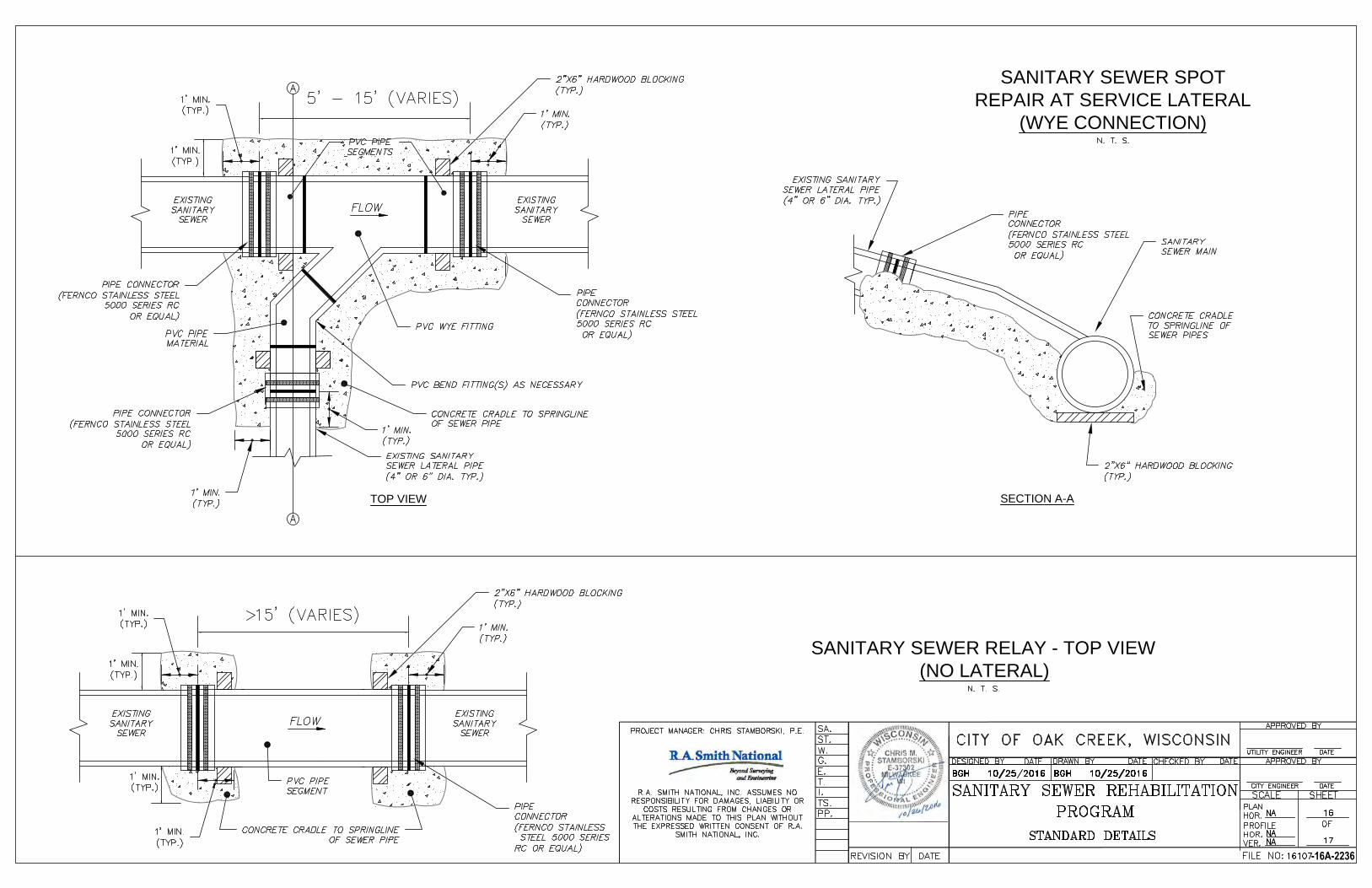
SECTION A-A
SANITARY SEWER SPOT
REPAIR AT SERVICE LATERAL
(WYE CONNECTION)
SANITARY SEWER RELAY - TOP VIEW
(NO LATERAL)
TOP VIEW
-16A-2236
AutoCAD SHX Text
A
AutoCAD SHX Text
A
AutoCAD SHX Text
FLOW
AutoCAD SHX Text
PVC BEND FITTING(S) AS NECESSARY
AutoCAD SHX Text
EXISTING SANITARY SEWER LATERAL PIPE (4" OR 6" DIA. TYP.)
AutoCAD SHX Text
EXISTING SANITARY SEWER
AutoCAD SHX Text
EXISTING SANITARY SEWER
AutoCAD SHX Text
2"X6" HARDWOOD BLOCKING (TYP.)
AutoCAD SHX Text
PIPE CONNECTOR (FERNCO STAINLESS STEEL 5000 SERIES RC OR EQUAL)
AutoCAD SHX Text
PIPE CONNECTOR (FERNCO STAINLESS STEEL 5000 SERIES RC OR EQUAL)
AutoCAD SHX Text
1' MIN. (TYP.)
AutoCAD SHX Text
EXISTING SANITARY SEWER LATERAL PIPE (4" OR 6" DIA. TYP.)
AutoCAD SHX Text
2"X6" HARDWOOD BLOCKING (TYP.)
AutoCAD SHX Text
PIPE CONNECTOR (FERNCO STAINLESS STEEL 5000 SERIES RC OR EQUAL)
AutoCAD SHX Text
CONCRETE CRADLE TO SPRINGLINE OF SEWER PIPES
AutoCAD SHX Text
1' MIN. (TYP.)
AutoCAD SHX Text
SANITARY SEWER MAIN
AutoCAD SHX Text
1' MIN. (TYP.)
AutoCAD SHX Text
1' MIN. (TYP.)
AutoCAD SHX Text
1' MIN. (TYP.)
AutoCAD SHX Text
PIPE CONNECTOR (FERNCO STAINLESS STEEL 5000 SERIES RC OR EQUAL)
AutoCAD SHX Text
N. T. S.
AutoCAD SHX Text
PVC PIPE SEGMENTS
AutoCAD SHX Text
FLOW
AutoCAD SHX Text
EXISTING SANITARY SEWER
AutoCAD SHX Text
EXISTING SANITARY SEWER
AutoCAD SHX Text
2"X6" HARDWOOD BLOCKING (TYP.)
AutoCAD SHX Text
PIPE CONNECTOR (FERNCO STAINLESS STEEL 5000 SERIES RC OR EQUAL)
AutoCAD SHX Text
1' MIN. (TYP.)
AutoCAD SHX Text
1' MIN. (TYP.)
AutoCAD SHX Text
1' MIN. (TYP.)
AutoCAD SHX Text
N. T. S.
AutoCAD SHX Text
1' MIN. (TYP.)
AutoCAD SHX Text
1' MIN. (TYP.)
AutoCAD SHX Text
FILE NO:
AutoCAD SHX Text
OF
AutoCAD SHX Text
VER.
AutoCAD SHX Text
HOR.
AutoCAD SHX Text
PROFILE
AutoCAD SHX Text
HOR.
AutoCAD SHX Text
PLAN
AutoCAD SHX Text
DATE
AutoCAD SHX Text
CITY ENGINEER
AutoCAD SHX Text
SHEET
AutoCAD SHX Text
SCALE
AutoCAD SHX Text
APPROVED BY
AutoCAD SHX Text
DATE
AutoCAD SHX Text
CHECKED BY
AutoCAD SHX Text
DATE
AutoCAD SHX Text
DRAWN BY
AutoCAD SHX Text
DATE
AutoCAD SHX Text
DESIGNED BY
AutoCAD SHX Text
DATE
AutoCAD SHX Text
REVISION BY
AutoCAD SHX Text
PP.
AutoCAD SHX Text
TS.
AutoCAD SHX Text
I.
AutoCAD SHX Text
T.
AutoCAD SHX Text
E.
AutoCAD SHX Text
G.
AutoCAD SHX Text
ST.
AutoCAD SHX Text
W.
AutoCAD SHX Text
SA.
AutoCAD SHX Text
CITY OF OAK CREEK, WISCONSIN
AutoCAD SHX Text
SANITARY SEWER REHABILITATION
AutoCAD SHX Text
16
AutoCAD SHX Text
17
AutoCAD SHX Text
NA
AutoCAD SHX Text
16107
AutoCAD SHX Text
BGH 10/25/2016
AutoCAD SHX Text
BGH 10/25/2016
AutoCAD SHX Text
NA
AutoCAD SHX Text
NA
AutoCAD SHX Text
APPROVED BY
AutoCAD SHX Text
UTILITY ENGINEER
AutoCAD SHX Text
DATE
AutoCAD SHX Text
PROGRAM
AutoCAD SHX Text
STANDARD DETAILS
AutoCAD SHX Text
PROJECT MANAGER: CHRIS STAMBORSKI, P.E.
AutoCAD SHX Text
R.A. SMITH NATIONAL, INC. ASSUMES NO RESPONSIBILITY FOR DAMAGES, LIABILITY OR COSTS RESULTING FROM CHANGES OR ALTERATIONS MADE TO THIS PLAN WITHOUT THE EXPRESSED WRITTEN CONSENT OF R.A. SMITH NATIONAL, INC.
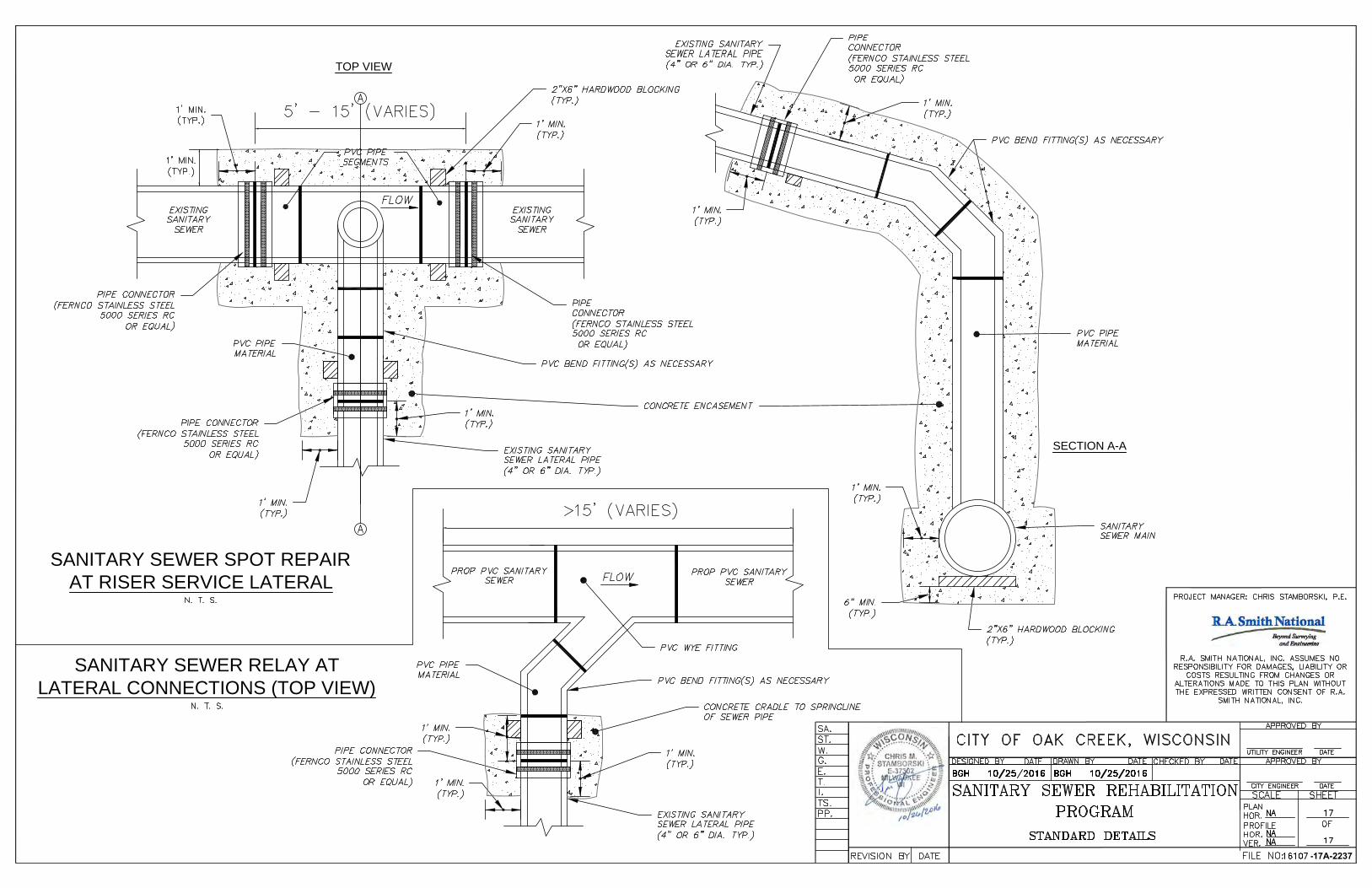
SECTION A-A
SANITARY SEWER SPOT REPAIR
AT RISER SERVICE LATERAL
SANITARY SEWER RELAY AT
LATERAL CONNECTIONS (TOP VIEW)
TOP VIEW
-17A-2237
AutoCAD SHX Text
A
AutoCAD SHX Text
A
AutoCAD SHX Text
FLOW
AutoCAD SHX Text
PVC BEND FITTING(S) AS NECESSARY
AutoCAD SHX Text
EXISTING SANITARY SEWER LATERAL PIPE (4" OR 6" DIA. TYP.)
AutoCAD SHX Text
EXISTING SANITARY SEWER
AutoCAD SHX Text
EXISTING SANITARY SEWER
AutoCAD SHX Text
2"X6" HARDWOOD BLOCKING (TYP.)
AutoCAD SHX Text
PIPE CONNECTOR (FERNCO STAINLESS STEEL 5000 SERIES RC OR EQUAL)
AutoCAD SHX Text
PIPE CONNECTOR (FERNCO STAINLESS STEEL 5000 SERIES RC OR EQUAL)
AutoCAD SHX Text
1' MIN. (TYP.)
AutoCAD SHX Text
EXISTING SANITARY SEWER LATERAL PIPE (4" OR 6" DIA. TYP.)
AutoCAD SHX Text
2"X6" HARDWOOD BLOCKING (TYP.)
AutoCAD SHX Text
PIPE CONNECTOR (FERNCO STAINLESS STEEL 5000 SERIES RC OR EQUAL)
AutoCAD SHX Text
1' MIN. (TYP.)
AutoCAD SHX Text
SANITARY SEWER MAIN
AutoCAD SHX Text
1' MIN. (TYP.)
AutoCAD SHX Text
1' MIN. (TYP.)
AutoCAD SHX Text
1' MIN. (TYP.)
AutoCAD SHX Text
PIPE CONNECTOR (FERNCO STAINLESS STEEL 5000 SERIES RC OR EQUAL)
AutoCAD SHX Text
N. T. S.
AutoCAD SHX Text
PVC PIPE SEGMENTS
AutoCAD SHX Text
PVC BEND FITTING(S) AS NECESSARY
AutoCAD SHX Text
1' MIN. (TYP.)
AutoCAD SHX Text
6" MIN. (TYP.)
AutoCAD SHX Text
1' MIN. (TYP.)
AutoCAD SHX Text
1' MIN. (TYP.)
AutoCAD SHX Text
FLOW
AutoCAD SHX Text
PVC BEND FITTING(S) AS NECESSARY
AutoCAD SHX Text
EXISTING SANITARY SEWER LATERAL PIPE (4" OR 6" DIA. TYP.)
AutoCAD SHX Text
PIPE CONNECTOR (FERNCO STAINLESS STEEL 5000 SERIES RC OR EQUAL)
AutoCAD SHX Text
1' MIN. (TYP.)
AutoCAD SHX Text
1' MIN. (TYP.)
AutoCAD SHX Text
PROP PVC SANITARY SEWER
AutoCAD SHX Text
PROP PVC SANITARY SEWER
AutoCAD SHX Text
1' MIN. (TYP.)
AutoCAD SHX Text
N. T. S.
AutoCAD SHX Text
FILE NO:
AutoCAD SHX Text
OF
AutoCAD SHX Text
VER.
AutoCAD SHX Text
HOR.
AutoCAD SHX Text
PROFILE
AutoCAD SHX Text
HOR.
AutoCAD SHX Text
PLAN
AutoCAD SHX Text
DATE
AutoCAD SHX Text
CITY ENGINEER
AutoCAD SHX Text
SHEET
AutoCAD SHX Text
SCALE
AutoCAD SHX Text
APPROVED BY
AutoCAD SHX Text
DATE
AutoCAD SHX Text
CHECKED BY
AutoCAD SHX Text
DATE
AutoCAD SHX Text
DRAWN BY
AutoCAD SHX Text
DATE
AutoCAD SHX Text
DESIGNED BY
AutoCAD SHX Text
DATE
AutoCAD SHX Text
REVISION BY
AutoCAD SHX Text
PP.
AutoCAD SHX Text
TS.
AutoCAD SHX Text
I.
AutoCAD SHX Text
T.
AutoCAD SHX Text
E.
AutoCAD SHX Text
G.
AutoCAD SHX Text
ST.
AutoCAD SHX Text
W.
AutoCAD SHX Text
SA.
AutoCAD SHX Text
CITY OF OAK CREEK, WISCONSIN
AutoCAD SHX Text
SANITARY SEWER REHABILITATION
AutoCAD SHX Text
17
AutoCAD SHX Text
17
AutoCAD SHX Text
NA
AutoCAD SHX Text
16107
AutoCAD SHX Text
BGH 10/25/2016
AutoCAD SHX Text
BGH 10/25/2016
AutoCAD SHX Text
NA
AutoCAD SHX Text
NA
AutoCAD SHX Text
APPROVED BY
AutoCAD SHX Text
UTILITY ENGINEER
AutoCAD SHX Text
DATE
AutoCAD SHX Text
PROGRAM
AutoCAD SHX Text
STANDARD DETAILS
AutoCAD SHX Text
PROJECT MANAGER: CHRIS STAMBORSKI, P.E.
AutoCAD SHX Text
R.A. SMITH NATIONAL, INC. ASSUMES NO RESPONSIBILITY FOR DAMAGES, LIABILITY OR COSTS RESULTING FROM CHANGES OR ALTERATIONS MADE TO THIS PLAN WITHOUT THE EXPRESSED WRITTEN CONSENT OF R.A. SMITH NATIONAL, INC.