Design Specifications & Requirements Manual SANITARY SEWER ... · Design Specifications &...
29
Design Specifications & Requirements Manual 3 SANITARY SEWER COLLECTION SYSTEM ..................... 1 3.1 DEFINITION ............................................................................................... 1 3.1.1 Public Sewage Systems ..................................................................... 1 3.1.2 Private Sewage Systems.................................................................... 1 3.2 NON-PERMITTED FLOWS ....................................................................... 1 3.3 LOCATION AND ALIGNMENT ................................................................. 1 3.3.1 Sanitary Sewers on Private Property .................................................. 1 3.4 DRAINAGE/SUB-DRAINAGE AREA PLANS ........................................... 1 3.5 EXTERNAL SEWERSHED LIMITS AND DRAINAGE AREAS ................. 2 3.6 DESIGN CHART ........................................................................................ 2 3.7 PEAKING FACTOR CALCULATION ........................................................ 2 3.8 DESIGN CRITERIA ................................................................................... 2 3.8.1 Tributary Areas Less Than 200 ha...................................................... 2 3.8.2 Tributary Area 200 ha and Larger ....................................................... 4 3.9 PEAK FLOW CALCULATION ................................................................... 4 3.10 MANNINGS ROUGHNESS COEFFICIENT ............................................... 5 3.11 PIPE SIZE .................................................................................................. 5 3.12 FLOW VELOCITY...................................................................................... 5 3.12.1 Minimum and Maximum Velocities ..................................................... 5 3.12.2 Minimum Grades ................................................................................ 5 3.13 PIPE MATERIAL ....................................................................................... 6 3.14 PIPE DEPTH AND BEDDING MATERIAL ................................................ 6 3.14.1 Minimums ........................................................................................... 6 3.14.2 Maximum Depth of Cover ................................................................... 6 3.14.3 Crossing Clearances .......................................................................... 7 3.14.4 Minimum Distance Between Sewers .................................................. 7 3.14.5 Trenchless Technologies.................................................................... 7
Transcript of Design Specifications & Requirements Manual SANITARY SEWER ... · Design Specifications &...

Design Specifications & Requirements Manual
3 SANITARY SEWER COLLECTION SYSTEM ..................... 1
3.1 DEFINITION ............................................................................................... 1
3.1.1 Public Sewage Systems ..................................................................... 1
3.1.2 Private Sewage Systems .................................................................... 1
3.2 NON-PERMITTED FLOWS ....................................................................... 1
3.3 LOCATION AND ALIGNMENT ................................................................. 1
3.3.1 Sanitary Sewers on Private Property .................................................. 1
3.4 DRAINAGE/SUB-DRAINAGE AREA PLANS ........................................... 1
3.5 EXTERNAL SEWERSHED LIMITS AND DRAINAGE AREAS ................. 2
3.6 DESIGN CHART ........................................................................................ 2
3.7 PEAKING FACTOR CALCULATION ........................................................ 2
3.8 DESIGN CRITERIA ................................................................................... 2
3.8.1 Tributary Areas Less Than 200 ha...................................................... 2
3.8.2 Tributary Area 200 ha and Larger ....................................................... 4
3.9 PEAK FLOW CALCULATION ................................................................... 4
3.10 MANNINGS ROUGHNESS COEFFICIENT ............................................... 5
3.11 PIPE SIZE .................................................................................................. 5
3.12 FLOW VELOCITY ...................................................................................... 5
3.12.1 Minimum and Maximum Velocities ..................................................... 5
3.12.2 Minimum Grades ................................................................................ 5
3.13 PIPE MATERIAL ....................................................................................... 6
3.14 PIPE DEPTH AND BEDDING MATERIAL ................................................ 6
3.14.1 Minimums ........................................................................................... 6
3.14.2 Maximum Depth of Cover ................................................................... 6
3.14.3 Crossing Clearances .......................................................................... 7 3.14.4 Minimum Distance Between Sewers .................................................. 7
3.14.5 Trenchless Technologies .................................................................... 7
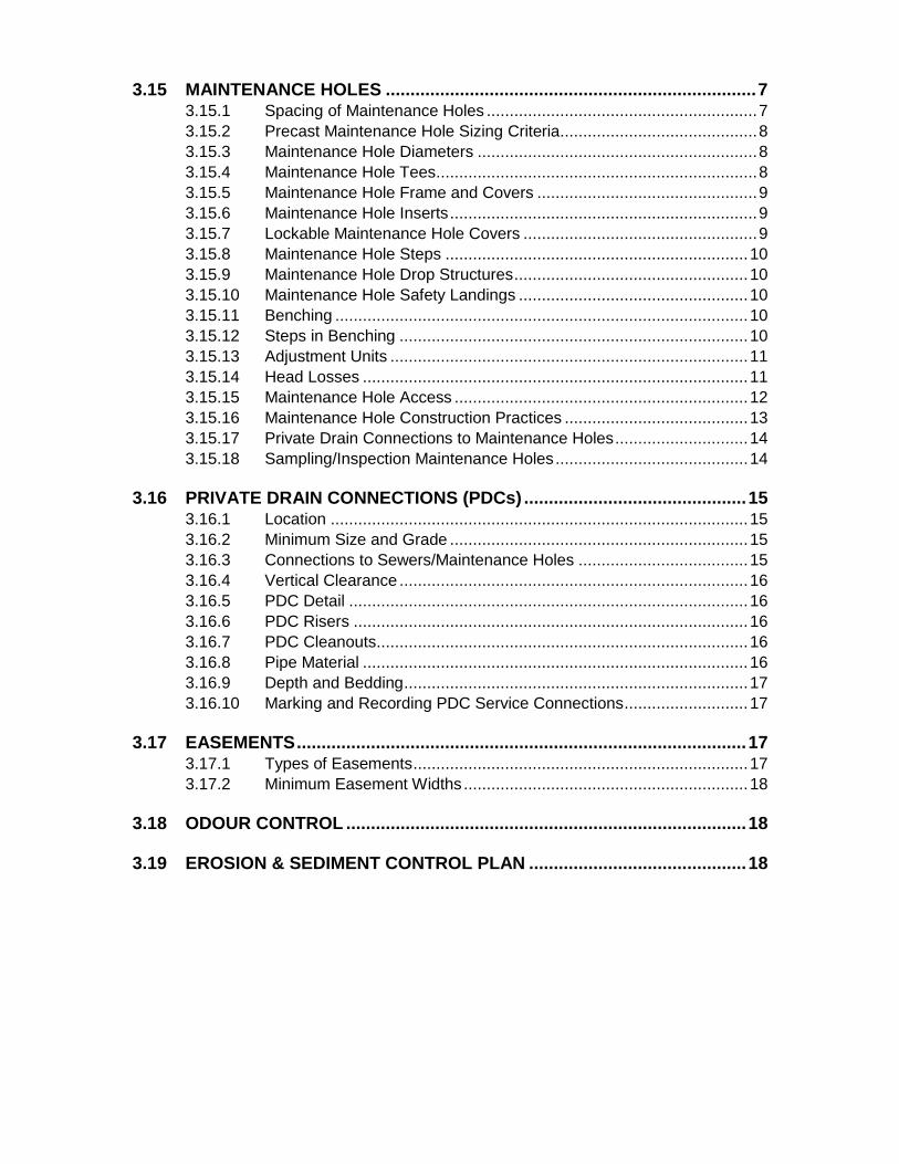
3.15 MAINTENANCE HOLES ........................................................................... 7
3.15.1 Spacing of Maintenance Holes ........................................................... 7
3.15.2 Precast Maintenance Hole Sizing Criteria ........................................... 8
3.15.3 Maintenance Hole Diameters ............................................................. 8
3.15.4 Maintenance Hole Tees ...................................................................... 8
3.15.5 Maintenance Hole Frame and Covers ................................................ 9
3.15.6 Maintenance Hole Inserts ................................................................... 9
3.15.7 Lockable Maintenance Hole Covers ................................................... 9
3.15.8 Maintenance Hole Steps .................................................................. 10
3.15.9 Maintenance Hole Drop Structures ................................................... 10
3.15.10 Maintenance Hole Safety Landings .................................................. 10
3.15.11 Benching .......................................................................................... 10
3.15.12 Steps in Benching ............................................................................ 10
3.15.13 Adjustment Units .............................................................................. 11
3.15.14 Head Losses .................................................................................... 11
3.15.15 Maintenance Hole Access ................................................................ 12
3.15.16 Maintenance Hole Construction Practices ........................................ 13
3.15.17 Private Drain Connections to Maintenance Holes ............................. 14
3.15.18 Sampling/Inspection Maintenance Holes .......................................... 14
3.16 PRIVATE DRAIN CONNECTIONS (PDCs) ............................................. 15
3.16.1 Location ........................................................................................... 15
3.16.2 Minimum Size and Grade ................................................................. 15
3.16.3 Connections to Sewers/Maintenance Holes ..................................... 15
3.16.4 Vertical Clearance ............................................................................ 16
3.16.5 PDC Detail ....................................................................................... 16
3.16.6 PDC Risers ...................................................................................... 16
3.16.7 PDC Cleanouts................................................................................. 16
3.16.8 Pipe Material .................................................................................... 16
3.16.9 Depth and Bedding ........................................................................... 17
3.16.10 Marking and Recording PDC Service Connections ........................... 17
3.17 EASEMENTS ........................................................................................... 17
3.17.1 Types of Easements ......................................................................... 17
3.17.2 Minimum Easement Widths .............................................................. 18
3.18 ODOUR CONTROL ................................................................................. 18
3.19 EROSION & SEDIMENT CONTROL PLAN ............................................ 18
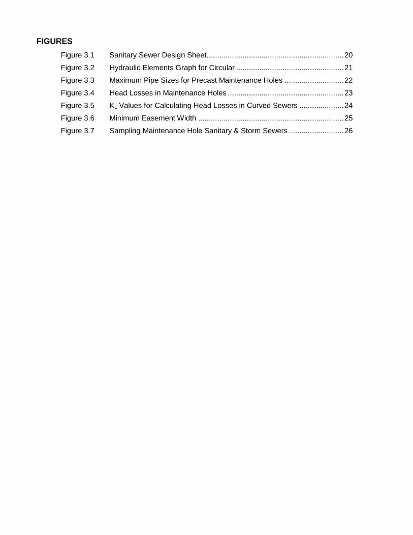
FIGURES
Figure 3.1 Sanitary Sewer Design Sheet ................................................................. 20
Figure 3.2 Hydraulic Elements Graph for Circular ................................................... 21
Figure 3.3 Maximum Pipe Sizes for Precast Maintenance Holes ............................ 22
Figure 3.4 Head Losses in Maintenance Holes ....................................................... 23
Figure 3.5 KL Values for Calculating Head Losses in Curved Sewers ..................... 24
Figure 3.6 Minimum Easement Width ..................................................................... 25
Figure 3.7 Sampling Maintenance Hole Sanitary & Storm Sewers .......................... 26

Design Specifications & Requirements Manual The Corporation of the City of London 3 - 1 Updated: August 2019
3 SANITARY SEWER COLLECTION SYSTEM
3.1 DEFINITION
3.1.1 Public Sewage Systems
A piped collection system that transports wastes of domestic origins which is human
body waste, toilet or bathroom waste, waste from other showers and tubs, liquid or water
borne culinary and sink water or laundry waste, and such other waste as is suitable for
treatment at a sewage treatment facility in accordance with City of London Waste
Discharge By-law WM-16 and Drainage By-law No. WM-4.
3.1.2 Private Sewage Systems
A sewage system (or systems), with a total design capacity of 10,000 litres per day or
less, shall be designed, constructed, operated and maintained in accordance with Part 8
of the Ontario Building Code.
A sewage system (or systems), with a total design capacity greater than 10,000 litres per
day, falls under the jurisdiction of the Ministry of the Environment, Conversation and
Parks.
3.2 NON-PERMITTED FLOWS
Connections from foundation, weeping tile drainage or roof drainage are not permitted to
enter the sanitary sewer system, in accordance with City of London Drainage By-law No.
WM-4, or any hazardous waste as defined under the EPA Regulation 347.
3.3 LOCATION AND ALIGNMENT
Generally sanitary sewers are to be located in front of, or are in locations accessible to
each lot and block facing a City Street. Sanitary sewers are to be located 1.5meters
from the centreline of the road (see DWG. U.C.C.-1M and U.C.C.-2M for details and
additional design information). Sanitary sewers are to be located on the inside loop of a
proposed crescent with the maintenance hole located at a 1.5 metre offset from the
centreline of the road.
Where a maintenance hole is designed to be located within the vicinity of a roundabout,
sanitary maintenance holes are not permitted to be located within the grassed area of
the roundabout. Sanitary maintenance holes must be located in the asphalt area of the
street, for maintenance purposes.
3.3.1 Sanitary Sewers on Private Property
Sanitary sewers on private property are regulated by the Ontario Building Code (OBC).
Where there are no specific regulations in the OBC, details from this manual will apply.
3.4 DRAINAGE/SUB-DRAINAGE AREA PLANS
Drainage/sub-drainage area limits for which sewers are to be designed for are to contain
and follow the lot/block lines to the proposed maintenance holes located on the R.O.W.
Note: All areas and populations are to be shown for each drainage/sub-drainage
areas.
Design Specifications & Requirements Manual The Corporation of the City of London 3 - 2 Updated: August 2019
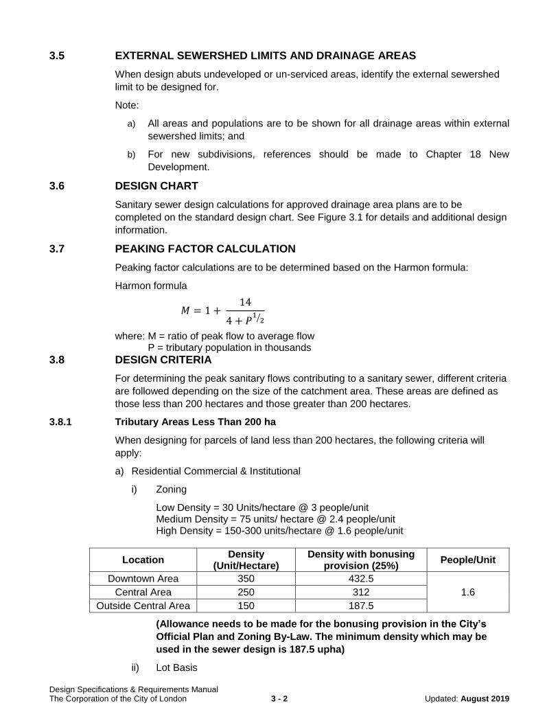
3.5 EXTERNAL SEWERSHED LIMITS AND DRAINAGE AREAS
When design abuts undeveloped or un-serviced areas, identify the external sewershed
limit to be designed for.
Note:
a) All areas and populations are to be shown for all drainage areas within external
sewershed limits; and
b) For new subdivisions, references should be made to Chapter 18 New
Development.
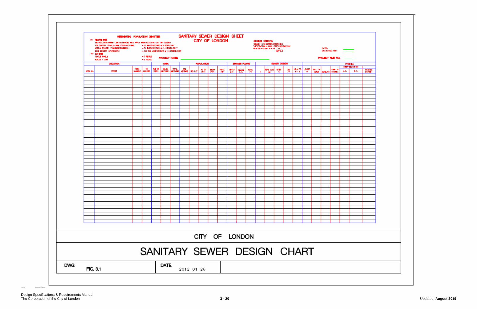
3.6 DESIGN CHART
Sanitary sewer design calculations for approved drainage area plans are to be
completed on the standard design chart. See Figure 3.1 for details and additional design
information.
3.7 PEAKING FACTOR CALCULATION
Peaking factor calculations are to be determined based on the Harmon formula:
Harmon formula
𝑀 = 1 + 14
4 + 𝑃1
2⁄
where: M = ratio of peak flow to average flow P = tributary population in thousands
3.8 DESIGN CRITERIA
For determining the peak sanitary flows contributing to a sanitary sewer, different criteria
are followed depending on the size of the catchment area. These areas are defined as
those less than 200 hectares and those greater than 200 hectares.
3.8.1 Tributary Areas Less Than 200 ha
When designing for parcels of land less than 200 hectares, the following criteria will
apply:
a) Residential Commercial & Institutional
i) Zoning
Low Density = 30 Units/hectare @ 3 people/unit Medium Density = 75 units/ hectare @ 2.4 people/unit High Density = 150-300 units/hectare @ 1.6 people/unit
Location Density
(Unit/Hectare) Density with bonusing
provision (25%) People/Unit
Downtown Area 350 432.5
1.6 Central Area 250 312
Outside Central Area 150 187.5
(Allowance needs to be made for the bonusing provision in the City’s
Official Plan and Zoning By-Law. The minimum density which may be
used in the sewer design is 187.5 upha)
ii) Lot Basis

Design Specifications & Requirements Manual The Corporation of the City of London 3 - 3 Updated: August 2019
Single Family = 3 people/unit Semi-detached = 6 people/unit
iii) Area Basis
Single Family = 30 units/hectare @ 3 people/unit Semi-detached = 30 units/hectare @ 3 people/unit Multi-family = 75 units/hectare @ 2.4 people/unit
iv) Commercial/Institutional = 100 people/hectare
v) Elementary School = maximum design number of students and employees,
with consumption at 30 Litres/person/day. In calculating the peak flow, it is
assumed that the total daily flow will occur over an 8 hour day and an
equivalent population will be determined by dividing the total flow by the
standard per capita flow of 230 Liters/day. If the design number is not known,
the population will be assumed to be 600.
vi) Secondary School = maximum design number of students and employees, with
consumption at 30 Litres/person/day. In calculating the peak flow, it is assumed
that the total daily flow will occur over an 8 hour day and an equivalent
population will be determined by dividing the total flow by the standard per
capita flow of 230 Liters/day. If the design number is not known, the population
will be assumed to be 1500.
vii) Church = 100 people/hectare
viii) Per Capita Flow = 230 litres/capita/day
ix) Uncertain Development Factor = 1.1
x) Peaking Factor = Harmon
xi) Infiltration = 8640 litres/hectare/day (0.100 l/s/ha)
NOTE: The above maximum densities under subsection i) Zoning correspond
to the maximum densities for each type of residential land use which
is permitted by the City of London Official Plan/London Plan (as
applicable). The density of residential land use for sanitary sewer
design purposes may be adjusted where deemed appropriate by the
City Engineer as more information becomes available in terms of the
development proposed for a specific parcel(s) of land and the
proposed residential land use densities. For specific development
applications, the above populations and/or per capita flow may be
adjusted where deemed appropriate by the City Engineer. In such
cases, the adjustment will be supported by alternate design standards
(e.g. Ontario Building Code, Ministry of the Environment,
Conservation and Parks)
b) Industrial
i) Flow Allowance – industrial = 25,000litres/hectare/day. This equals 100 pph.
NOTE: Industrial users with water consumption/sewage discharge design
criteria greater than this will be considered heavy water users. Heavy
water users should consult with the City of London with respect to
their specific requirements for water use and sewage discharge in

Design Specifications & Requirements Manual The Corporation of the City of London 3 - 4 Updated: August 2019
terms of confirming capacity is available within the municipal
infrastructure to meet their needs. Heavy water users should also
consult with the City of London prior to any upgrades which will
increase their discharge rates to the municipal sewer system.
ii) Uncertain Development Factor = 1.1
iii) Peaking Factor = 0.8 x Harmon
iv) Infiltration = 8640 litres/hectare/day (0.100 l/s/ha)
3.8.2 Tributary Area 200 ha and Larger
When designing for parcels of land 200 hectares and larger, the following criteria will apply:
a) Residential, Commercial and Institutional
i) Population Allowance = 55 people per hectare (gross area with any ESA areas
netted out)
Note: The above maximum density is from the City of London Official Plan. The
density may be adjusted by the City Engineer as more information
becomes available on a specific parcel of land.
ii) Per Capita Flow = 230 litres/capita/day
iii) Peaking Factor = Harmon
iv) Uncertain Development Factor = 1.0
v) Infiltration Allowance = 8640 litres/hectare/day (0.100 l/s/ha)
b) Industrial
i) Flow Allowance – industrial = 20,000 litres/hectare/day [for our internal
discussion as to whether this should be 20 or 25,000]
Note: Industrial users with water consumption/sewage discharge design
criteria greater than this will be considered heavy water users. Heavy
water users should consult with the City of London with respect to their
specific requirements for water use and sewage discharge in terms of
confirming capacity is available within the municipal infrastructure to
meet their needs. Heavy water users should also consult with the City of
London prior to any upgrades which will increase their discharge rates to
the municipal sewer system.
ii) Peaking Factor = 0.8 x Harmon
iii) Uncertain development factor = 1.0
iv) Infiltration allowance = 8640 litres/hectare/day (0.100 l/s/ha)
3.9 PEAK FLOW CALCULATION
Peak flow calculations are to be determined based on the following formula:
𝑄 (𝑝𝑒𝑎𝑘 𝑓𝑙𝑜𝑤 𝐿/𝑠) = (𝑝𝑜𝑝𝑢𝑙𝑎𝑡𝑖𝑜𝑛×𝑝𝑒𝑟 𝑐𝑎𝑝𝑖𝑡𝑎 𝑓𝑙𝑜𝑤 ×𝑝𝑒𝑎𝑘𝑖𝑛𝑔 𝑓𝑎𝑐𝑡𝑜𝑟×𝑢𝑛𝑐𝑒𝑟𝑡𝑎𝑖𝑛𝑡𝑦
24 ×60 ×60) + 𝑖𝑛𝑓𝑖𝑙𝑡𝑟𝑎𝑡𝑖𝑜𝑛
where: Peak Flow (Q) = L/s Per Capita Flow = 230 litres/capita/day Peaking Factor (H) = Harmon (section 3.7)
Design Specifications & Requirements Manual The Corporation of the City of London 3 - 5 Updated: August 2019
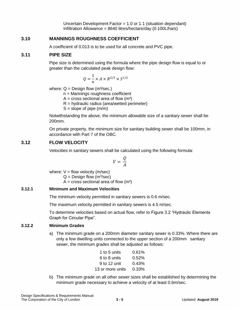
Uncertain Development Factor = 1.0 or 1.1 (situation dependant) Infiltration Allowance = 8640 litres/hectare/day (0.100L/ha/s)
3.10 MANNINGS ROUGHNESS COEFFICIENT
A coefficient of 0.013 is to be used for all concrete and PVC pipe.
3.11 PIPE SIZE
Pipe size is determined using the formula where the pipe design flow is equal to or
greater than the calculated peak design flow:
𝑄 =1
𝑛× 𝐴 × 𝑅2/3 × 𝑆1/2
where: Q = Design flow (m³/sec.) n = Mannings roughness coefficient A = cross sectional area of flow (m²) R = hydraulic radius (area/wetted perimeter) S = slope of pipe (m/m)
Notwithstanding the above, the minimum allowable size of a sanitary sewer shall be
200mm.
On private property, the minimum size for sanitary building sewer shall be 100mm, in
accordance with Part 7 of the OBC.
3.12 FLOW VELOCITY
Velocities in sanitary sewers shall be calculated using the following formula:
𝑉 = 𝑄
𝐴
where: V = flow velocity (m/sec) Q = Design flow (m3/sec) A = cross sectional area of flow (m²)
3.12.1 Minimum and Maximum Velocities
The minimum velocity permitted in sanitary sewers is 0.6 m/sec.
The maximum velocity permitted in sanitary sewers is 4.5 m/sec.
To determine velocities based on actual flow, refer to Figure 3.2 “Hydraulic Elements
Graph for Circular Pipe”.
3.12.2 Minimum Grades
a) The minimum grade on a 200mm diameter sanitary sewer is 0.33%. Where there are
only a few dwelling units connected to the upper section of a 200mm sanitary
sewer, the minimum grades shall be adjusted as follows:
1 to 5 units 0.61%
6 to 8 units 0.52%
9 to 12 unit 0.43%
13 or more units 0.33%
b) The minimum grade on all other sewer sizes shall be established by determining the
minimum grade necessary to achieve a velocity of at least 0.6m/sec.

Design Specifications & Requirements Manual The Corporation of the City of London 3 - 6 Updated: August 2019
3.13 PIPE MATERIAL
Both rigid and flexible pipe are permitted in the construction of sanitary sewer systems
including private drain connections. These materials include concrete and polyvinyl
chloride.
The criteria for these materials are described in City of London Standard Contract
Documents - Section 410.05.01.
On private property, materials for sanitary building sewers and private sewers shall
comply with Part 7 of the OBC.
3.14 PIPE DEPTH AND BEDDING MATERIAL
3.14.1 Minimums
The minimum depth of a sanitary sewer shall be 2.4 m from the finished ground
elevation to the obvert of the pipe unless otherwise approved by the City Engineer.
Note, where frost protection is warranted, insulation is required, as per the City of
London Drawing Standard W-CS-68.
3.14.2 Maximum Depth of Cover
a) Concrete Pipe
i) See City of London SW-1.0 and SW-1.1 for details and additional design
information for bedding standards for Class A, B and C beddings.
ii) Municipal Projects
The maximum allowable cover permitted on concrete pipe to be constructed
under a Municipal or Capital Works Project is to be based on OPSD 807.010,
807.030, 807.040 and 807.050.
Where the pipe required exceeds the OPSD charts, the Pipe Pac Program 2000
will be used, utilizing the following variables:
all units are in metric and conform to C.S.A. standards
wall thickness is based on C.S.A A257.2M, Type B wall
soil density = 2000 kg/m3
Ontario Highway Bridge Design Code (OHBDC)
live load magnitude = 25 tons
projection ratio = 0.70
lateral pressure ratio = 0.33
lateral pressure friction ‘m’ = 0.70
settlement ratio = 0.70
k-mu(μ) = 0.1924
variable bedding factors B - Lf = 1.9 C - Lf = 1.5
rsdp = 0.49 (calculated)
factors of safety
0.3mm crack D-load = 1.00
ultimate earth and live load = (ASTM C 76M)
DL.03 ≤ 100 N/m/mm = 1.50
DL.03 ≥ 140 N/m/mm = 1.25
DL.03 between 100 and 140 N/m/mm = interpolated
Design Specifications & Requirements Manual The Corporation of the City of London 3 - 7 Updated: August 2019
positive projection embankment installation
maximum depth of cover is based on transition width design
depth of ground is measured from the ultimate finished ground elevation to the outside top of pipe.
iii) New Subdivisions:
The maximum allowable cover permitted on concrete pipe to be constructed in a
new subdivision is to be designed based on transition width, and utilize
reinforced concrete pipe only, in accordance with OPSD 807.030 and 807.050
(Positive Projecting Embankment Installation only).
Where the pipe required exceeds the OPSD Charts, the Pipe Pac Program 2000
utilizing the variables noted in 3.14.2.ii) or 5.13.2.ii) above, or First Principles
(using City of London Variables) will be used.
b) Flexible Pipe
The maximum allowable cover permitted on flexible pipe is 10.5 m. The following
bedding types are to be used:
for up to 4.5 m - Type 1 (see City of London SW-1.0)
for up to 10.5 m Type 2 (see City of London SW-1.0)
c) Maximum Depth of Cover
Where trench conditions are expected to exhibit seeping ground water in silt or fine
sand, specified bedding will be defined as 19mm crushed stone entirely surrounded
by geotextile.
3.14.3 Crossing Clearances
There are minimum clearances required when sanitary sewers cross other services. In
all cases this is measured from outside wall diameter to outside wall diameter.
When crossing over or under a storm sewer, 230mm clearance is required.
For vertical clearances from the sanitary sewer to the watermain see Water Design
Standards Chapter 7 Section 7.4.7.2.
3.14.4 Minimum Distance Between Sewers
The minimum distance between sewers shall be 3.0m as per drawing UCC-1M and
UCC-2M. Special cases to be reviewed for site specific design choices and depths.
3.14.5 Trenchless Technologies
When trenchless installation methods are being considered for new works, please refer
to Section 17 – Trenchless Technologies (for New Construction).
3.15 MAINTENANCE HOLES
3.15.1 Spacing of Maintenance Holes
The maximum spacing between sanitary maintenance holes shall be 99 metres
measured horizontally or 110 metres measured vertically from the top of the
maintenance hole, to the springline of the pipe, along the springline to the next
maintenance hole and vertically to the top of the maintenance hole.
Design Specifications & Requirements Manual The Corporation of the City of London 3 - 8 Updated: August 2019
When spacing of a maintenance hole dictates that the maintenance hole should be
placed within the vicinity of a roundabout, sanitary maintenance holes are not permitted
to be located within the grassed area of the roundabout. Sanitary maintenance holes
must be located within the apron of the island, for maintenance purposes.
Required where there is a change in the direction of the flow, slopes, a change in the
diameter of sewers, and/or a lateral sewer connection. Note, a minimum 300mm
clearance is required between services within a maintenance hole.
3.15.2 Precast Maintenance Hole Sizing Criteria
All sizing of sanitary precast maintenance holes are based on incoming and outgoing
pipe sizes and should be sized and conform to Figure 3.3.
Note, a minimum 300mm clearance is required between services within a
maintenance hole.
3.15.3 Maintenance Hole Diameters
Precast maintenance hole diameter requirements are as follows:
a) 1200mm Diameter
See OPSD 701.010 and OPSD 701.030 for details and additional design information.
b) 1500mm Diameter
See OPSD 701.011 and OPSD 701.040 for details and additional design information.
c) 1800mm Diameter
See OPSD 701.012 and OPSD 701.050 for details and additional design information.
d) 2400mm Diameter
See OPSD 701.013 and OPSD 701.060 for details and additional design information.
e) 3000mm Diameter
See OPSD 701.014 and OPSD 701.070 for details and additional design information.
f) 3600mm Diameter
See OPSD 701.015 and OPSD 701.080 for details and additional design information.
Poured Maintenance Holes
Required for maintenance holes which exceed the above maximum pipe sizes for
precast maintenance holes. Note, certification by a Structural Engineer is required
for all poured maintenance holes.
3.15.4 Maintenance Hole Tees
Maintenance Hole tees are not allowed for any sanitary sewer less than 1200mm
diameter. For sanitary trunk sewers greater than 1200mm diameter, refer to the storm
sewer section 5.14.4. Ensure sewers which slope away from the maintenance hole, but
are not intended to take flows from the maintenance hole, have the inverts high enough
to not accept sewage.

Design Specifications & Requirements Manual The Corporation of the City of London 3 - 9 Updated: August 2019
3.15.5 Maintenance Hole Frame and Covers
Maintenance hole frames and covers are required for all maintenance holes and shall
conform with OPSD 401.01. See OPSD 401.01 for details and additional design
information.
a) Maintenance hole frames and covers are to be clear of curb and gutters on bends in
the road for new construction. Maintenance hole frames and covers may be located
in the curb and gutter on reconstruction projects, only as approved.
b) Maintenance hole frames and covers and by association steps must be aligned to
avoid being located in the wheel path of the street, and to be located above a
benching platform, i.e. to avoid conflict with an inletting or outletting sewer pipe,
respectively. Proposed location of maintenance hole frames and covers and by
association steps must be shown in plain view on the engineering drawings,
represented by a solid circle reflecting the above requirements.
3.15.6 Maintenance Hole Inserts
3.15.6.1 Use of Maintenance Hole Inserts Required During Construction
The use of inserts in sanitary maintenance holes will be required in areas of new
construction until such time as the roadway is paved with the top asphalt layer.
3.15.6.2 Watertight Maintenance Hole Lids/Covers
Watertight maintenance hole lids are required when sanitary maintenance holes are
located within overland storm flow routes. These locations are within flood plain areas,
within gutter locations and within an easement and/or open space area where overland
flow is directly over and or adjacent to the maintenance hole lids. Watertight
maintenance hole lids are also required under sanitary surcharge conditions. (See City
of London SW-5.3 for details and additional design information).
Watertight maintenance hole lids are not required under the following circumstances:
a) Where design dictates that the maintenance hole lids end up in the curb and
gutter and where it is possible to rotate the cone so that the maintenance hole lid
is clear of the gutter, the cone should be rotated such that a water tight lid would
not be required;
b) Where, in the profile design of the street, the maintenance hole is located in the
low point of an overland flow route, the maintenance hole may be in standard
location, but would be submerged under a greater than two year storm event.
Maintenance holes located in a standard location on streets that carry an
overland flow route with a continuous grade, or cascading grade (even though
some of these may be briefly submerged) do not require water tight lids.
3.15.7 Lockable Maintenance Hole Covers
Lockable maintenance hole covers are required to reduce access by the public. They
can be located through park blocks, open space blocks, pumping stations or pollution
control plants. See OPSD 401.06 for details and additional design information.
Design Specifications & Requirements Manual The Corporation of the City of London 3 - 10 Updated: August 2019
3.15.8 Maintenance Hole Steps
Maintenance hole steps are required for access and are to conform with one of the
following:
a) Maintenance Hole Steps - Hollow
See OPSD 405.010 for details and additional design information.
b) Maintenance Hole Steps - Solid
See OPSD 405.020 for details and additional design information.
Note:
i) All steps are to be galvanized steel or aluminium; and
ii) A detail or restoration plan is required for the relocation of maintenance hole
steps within existing maintenance holes, where applicable; and
iii) Maintenance hole steps shall be located to avoid conflict with an inletting or
outletting sewer pipe. Access to maintenance holes must be above the
benching platform.
c) Reference to Section 3.15.5 for alignment information for location requirements for
the maintenance hole frame and cover.
3.15.9 Maintenance Hole Drop Structures
Sanitary drop structures are required when the difference in invert elevations between
the upstream and outlet sewers in the maintenance hole is equal to or greater than 0.6
metres. (See City of London SW-2.0 for details and any additional design information).
3.15.10 Maintenance Hole Safety Landings
Maintenance hole safety landings are required at the mid-point depth of the maintenance
hole, when the depth of the maintenance hole is between 5.0 and 10.0 metres.
Additional safety landings are required at third-point depths, when the maintenance hole
is equal to or greater than 10.0m to 15.0m deep. See City of London SW-2.5 for details
and additional design information.
Note: Incoming pipes are to be below safety landings, where possible.
3.15.11 Benching
All maintenance holes require benching at the bottom of the maintenance hole and
should conform to OPSD 701.021. Benching height should be increased to obvert to
increase hydraulic benefit as required.
Note: Where benching is different from OPSD 701.021, a benching detail is
required.
3.15.12 Steps in Benching
Steps in maintenance hole benching are required when the pipe diameter is greater than
900mm and benched to springline, and when the pipe diameter is greater than 450mm
and benched to crown. See City of London SW-5.2 for details and additional design
information.
Design Specifications & Requirements Manual The Corporation of the City of London 3 - 11 Updated: August 2019
3.15.13 Adjustment Units
Maintenance hole adjustment units are required on all maintenance holes to ensure that
proper grade is provided between the top of the maintenance hole and the maintenance
hole lid. Ensure that the difference in grade between the maintenance hole lid and the
first ladder rung does not exceed 600mm. See City of London SW-5.0 for details and
additional design information. Clay brick will not be allowed for use as maintenance hole
adjustment units.
3.15.14 Head Losses
a) Generally, when velocities in the downstream pipe from a maintenance hole exceed
a velocity of 1.2 m/s, head losses must be accounted for in the design of the sewer
and larger PDC’s. In order to absorb head losses that may exist in maintenance
holes, it may be necessary to improve the benching in the maintenance hole or
increase the size of the downstream pipe where possible. Lowering the crown of the
outgoing sewer below the crown of the incoming sewer by the amount equal to the
head loss, however, is the most effective method of accounting for head loss in most
cases.
b) Drops in maintenance holes to compensate for Head Loss (HL) shall be calculated
using the following formula:
𝐻𝐿 = 𝐾𝐿 𝑉2
2𝑔
where: KL = Head loss coefficient V = downstream velocity (m/s) g = 9.8 m/sec2
Note: Also see Figure 5.6 for quick reference for head losses in maintenance holes,
and Section 5.14.10 for benching.
c) Head loss coefficients (KL) are to be applied as follows:
i) 90 degrees
No benching or deflector, or where they are only up to spring line.
KL =1.5
ii) 90 degrees
Benching or deflector to crown of sewers.
KL = 1.0
iii) Less than 90 degrees
Multiply the head loss coefficient for a 90 degree bend by a head loss ratio factor
from the following chart:
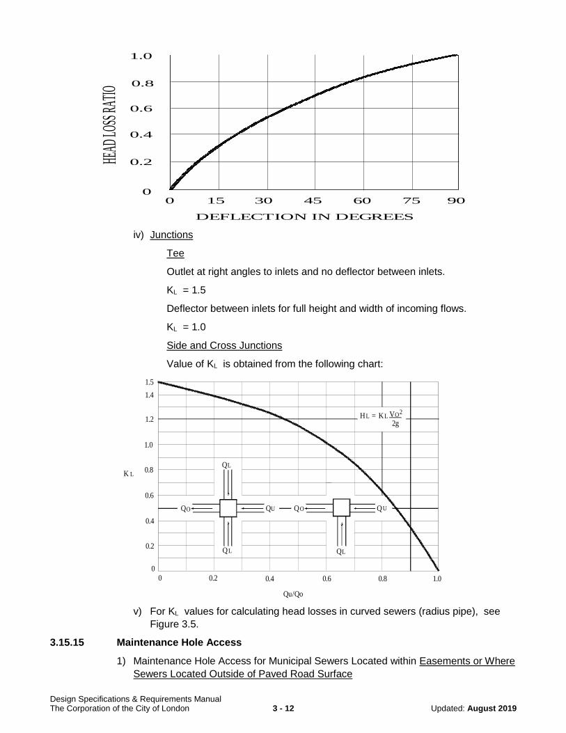
Design Specifications & Requirements Manual The Corporation of the City of London 3 - 12 Updated: August 2019
iv) Junctions
Tee
Outlet at right angles to inlets and no deflector between inlets.
KL = 1.5
Deflector between inlets for full height and width of incoming flows.
KL = 1.0
Side and Cross Junctions
Value of KL is obtained from the following chart:
v) For KL values for calculating head losses in curved sewers (radius pipe), see
Figure 3.5.
3.15.15 Maintenance Hole Access
1) Maintenance Hole Access for Municipal Sewers Located within Easements or Where
Sewers Located Outside of Paved Road Surface
DEFLECTION IN DEGREES
0 15 30 45 60 75 90
HEAD
LOSS
RATIO
1.0
0.8
0.6
0.4
0.2
0
Qu/Qo
0 0.2 0.4 0.6 0.8 1.0
K L
0
0.2
0.4
0.6
0.8
1.0
1.2
1.4
1.5
Q
Q Q
Q
Q
Q
Q
L
LL
O U UO
LLH = K V2gO2

Design Specifications & Requirements Manual The Corporation of the City of London 3 - 13 Updated: August 2019
a) Access to maintenance holes for the purpose of maintenance is to be provided in
all circumstances. When designing maintenance access roads for sewers,
generally the maintenance access road/path will have a 3.0 meter wide hard
asphalt surface with a 4.0 meter wide granular base.
Adequate curves and turn-around facilities are required for maintenance vehicles
to manoeuvre. Slopes (4% maximum), cross falls (2% minimum to 4.5%
maximum) and drainage of access roads are also to be addressed in the design.
b) Where sanitary sewer maintenance holes are installed below the flood line, the
engineer shall be consulted and access road alternatives may be considered in
this situation.
Note:
i. A 0.3m separation is required between the maintenance access and the
top/bottom of any slopes; fences; and property line(s); and
ii. The design and construction of sewer maintenance access roads in City
Parks and Open Spaces will require the review and approval of both
Parks Planning & Design and the Environmental & Engineering
Services Department. Wherever possible, sewer access roads in City
Parks and Open Spaces shall be integrated into the public open space
pathway networks and respect the City's natural heritage features.
See Section 3.17 for easement requirements.
2) Maintenance Hole Access Below Flood Line
Where sanitary sewer maintenance holes are installed below the 100 year flood line,
the engineer shall be consulted, and access road alternatives may be considered in
this situation.
In this situation, maintenance hole lids must conform to 3.15.6.
3.15.16 Maintenance Hole Construction Practices
a) The void between the sewer pipe and the cored hole of the precast maintenance hole
section shall be filled with cement bricks and approved non-shrinkable grout. Pre
booted maintenance holes will be allowed but only with previous approval by the City.
All joints between bricks are to be completely filled with concrete mortar. Bricks are to
be parged on the outside. Parging shall contain an approved bonding agent. All mortar
and approved non-shrinkable grout shall be mixed and placed in accordance with the
manufactures specifications.
b) All precast maintenance hole section joints shall contain an approved rubber gasket.
In areas of high groundwater, exterior joint collars or external wrapping (eg. ‘Cretex’
waterproofing or equivalent, installed as per manufacturer’s specifications) of the
maintenance hole joints will be required. This requirement may be waived if it can be
demonstrated that, based on specific groundwater conditions, the standard rubber
gasket is sufficient to prevent infiltration.
c) A minimum 300mm vertical/horizontal clearance between openings on the inside of
the maintenance hole is required for all sewer and PDC connections.
d) All maintenance hole frame and covers shall be adjusted to the finished road grade by
means of metal shims at each corner or by means of an approved precast adjustment

Design Specifications & Requirements Manual The Corporation of the City of London 3 - 14 Updated: August 2019
ring. Metal shims are to be at least 75mm x 200mm (3" x 8") and their thickness is to
be determined by the adjustment required. The space between the bottom of the
maintenance hole frame and cover and the top of the precast maintenance hole is to
be at minimum the thickness of one adjustment unit and at maximum 300mm. See
City of London SW-5.0 for details and additional design information.
e) Where adjacent maintenance holes are located in close proximity to one another, the area between the adjacent maintenance holes shall be backfilled in accordance with the specifications in the following table:
Distance Between Adjacent
Maintenance Holes Material
0.6 metres or less concrete or crushed stone
0.6 metres to 2.4 metres granular material
more than 2.4 metres approved native material or granular material
The above noted backfill shall be compacted to the standard Proctor Density
specified in the soils report, or as approved by the City Engineer.
3.15.17 Private Drain Connections to Maintenance Holes
Residential sanitary private drain connections are NOT to be constructed into any
sanitary maintenance holes.
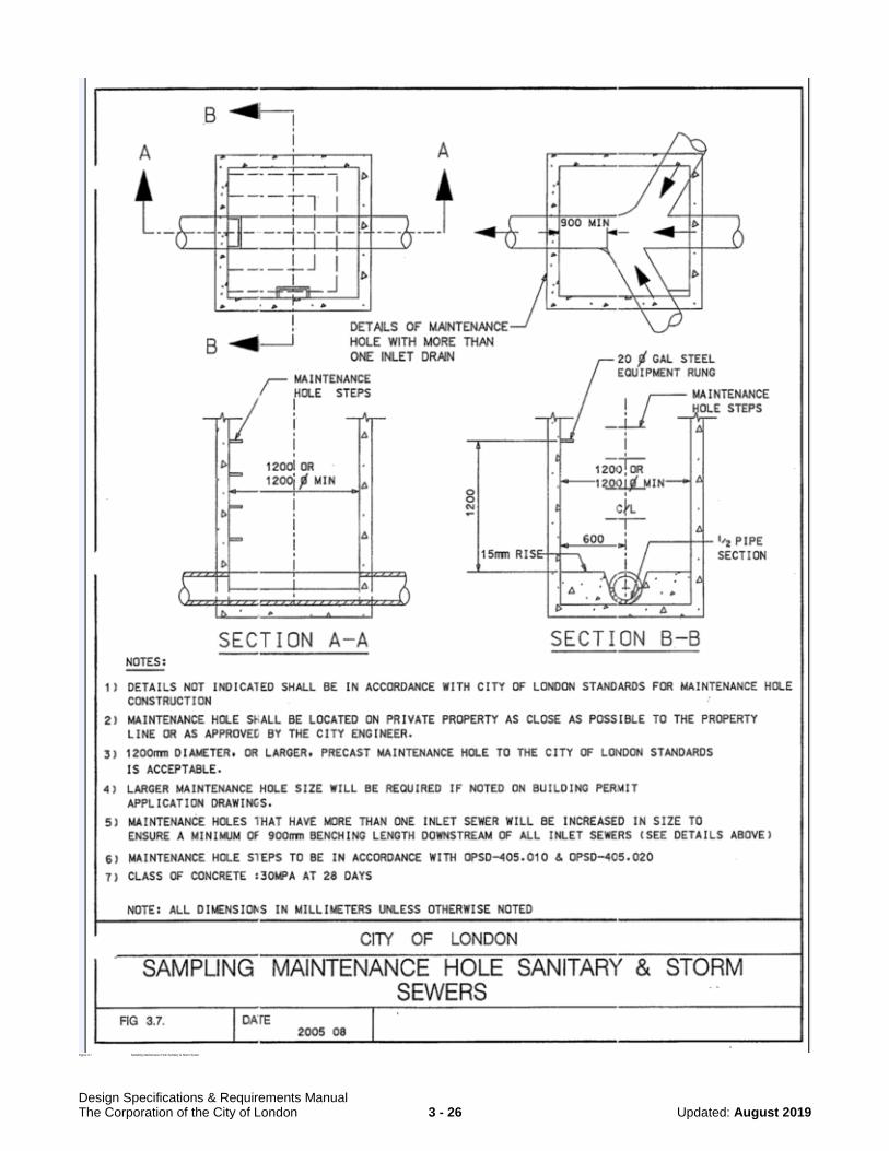
3.15.18 Sampling/Inspection Maintenance Holes
a) Requirements
Sampling/Inspection maintenance holes are typically required where Institutional,
Commercial and Industrial developments outlet to sanitary sewers owned and
maintained by the City. Sampling/inspection maintenance holes are required for all
industrial and commercial sites.
b) Location
If required, Sampling/Inspection Maintenance Holes shall be located on private
property as close as possible to the property line, or as approved by the City
Engineer.
c) Minimum Size
Sampling/Inspection Maintenance Holes shall be a minimum of 1200mm diameter.
A larger diameter Maintenance Hole may be required if noted on the Building Permit
Application Drawings.
Sampling/Inspection Maintenance Holes that have more than one inlet sewer shall
be increased in size to ensure that there is a minimum of 0.9m benching length
downstream of all inlet sewers.
There are to be no drop structures (internal or external) located at
sampling/inspection maintenance holes that are required for City sampling purposes.
Maintenance Holes shall be to OPSD standards – see Section 3.15.3, and Figure 3.7
for further details.

Design Specifications & Requirements Manual The Corporation of the City of London 3 - 15 Updated: August 2019
3.16 PRIVATE DRAIN CONNECTIONS (PDCS)
3.16.1 Location
PDCs to single family and semi-detached lots are to be located in accordance with City of
London SW-7.0.
PDCs to multi-family (town housing, row housing and apartments), commercial and
industrial blocks are to be connected to a maintenance hole on the R.O.W. See section
3.16.3 for further details.
PDC's shall be installed at 90° to the sewer main where possible. Under no circumstances
will flow from the PDC enter the main against the flow in the main. Where horizontal or
vertical bends are required, long radius sweeps shall be used. Short bends are not
acceptable. Single family and semi-detached lot Sanitary PDC's shall NOT be connected
to a maintenance hole.
Note: Where design constraints arise (ie: top end of cul-de-sac or crescent), PDCs may
have to be located in reverse location and identified as such on the servicing
drawings.
3.16.2 Minimum Size and Grade
a) The minimum diameter and grade of a PDC for residential, single family and semi-
detached lots is 100mm @ 2.0%.
b) The minimum diameter and grade of a PDC for a residential multi-family block is
150mm diameter @1.0%.
c) The minimum diameter and grade of a PDC for a non-residential block is 150mm
diameter @ 1.0%.
d) The minimum diameter and grade of a PDC for a commercial block is 150mm
diameter @ 1.0%.
e) The minimum diameter and grade of a PDC for an institutional block is 200mm
diameter @1.0%.
Note: The actual size of the PDC required for multi-family, non-residential, commercial
and institutional blocks is dependent on the flows.
All PDC’s must have a minimum slope of 1% at a constant gradient.
3.16.3 Connections to Sewers/Maintenance Holes
a) Residential
PDCs 100mm and 150mm in diameter must be connected to the main sewer.
Residential sanitary PDCs are not to be constructed into any sanitary maintenance
hole.
b) Multi-family, Commercial, Institutional and Industrial
PDCs 200mm in diameter and larger are to be connected to the main sewer at
maintenance holes.
c) Connections to Existing Sewers for Lot Infill Situations
i. In a situation where a lot severance or lot infill condition exists, and a new
sanitary service will be connected to an existing sanitary mainline, the advocate

Design Specifications & Requirements Manual The Corporation of the City of London 3 - 16 Updated: August 2019
of the severance/infill, or his agent, must determine if the existing sanitary sewer
is a combined or poorly separated sewer and is therefore at risk of surcharging,
or if the sewer is a dedicated sanitary sewer but has a history of surcharging.
This information can be obtained from Wastewater Engineering Division. If it is
determined that there is a surcharge risk, the development advocate must
provide surcharge protection to his development.
ii. When connecting PDC’s to existing sewers in a lot infill situation, connections must be made utilizing an approved saddle or premanufactured tee, in accordance with OPSS 410, as amended by the Supplemental Standards for Sewer and Water (SW) in the City of London Standard Contract documents for Municipal Connection Projects.
d) Maximum Depth of Sewer Where Direct PDC Connections Permitted
Direct connection of private drain connections to sanitary sewers greater than 8
meters in depth will not be permitted. Where a sanitary sewer is greater than 8
meters in depth, and local servicing is required, it will be required to provide a
shallower local sewer to which private drain connections may be made. Deviations
from this will require the approval of the Director of Wastewater and Treatment or the
City Engineer.
3.16.4 Vertical Clearance
For vertical clearances from the sanitary PDC to the watermain see Water Design
Standards Chapter 7 Section 7.4.7.2.
3.16.5 PDC Detail
Typical PDC connection to the main shall be as per City of London SW-6.0.
3.16.6 PDC Risers
a) Type I
Required for sewer depths greater than or equal to 4.5 m and for excavations in stable
bank conditions, see City of London SW-6.1 for details and additional design
information. When the PDC is installed between 45° and 67.5°, an approved
controlled settlement joint shall be installed at the tee.
b) Type II
Required for sewer depths greater than or equal to 4.5 m and for excavations in
unstable bank conditions, see City of London SW-6.2 for details and additional design
information. When the PDC is installed between 45° and 67.5°, an approved
controlled settlement joint shall be installed at the tee.
3.16.7 PDC Cleanouts
Where removal is requested and approval is granted by the City Engineer, the cleanout
and tee must be removed entirely. The owner may be required to install a new PDC.
Approval will be given on a case-by-case basis and will apply to the entire phase of
development.
3.16.8 Pipe Material
Refer to Section 3.13

Design Specifications & Requirements Manual The Corporation of the City of London 3 - 17 Updated: August 2019
3.16.9 Depth and Bedding
The minimum depth of a sanitary PDC shall be 2.4 metres from the finished property line
elevation to the obvert of the PDC. The maximum cover on a sanitary PDC shall be
based on the following:
a) Concrete Pipe
The maximum allowable cover permitted on concrete PDCs is to be as per Section
3.14.2 a).
b) Flexible Pipe
The maximum allowable cover permitted on flexible PDCs is to be as per Section
3.14.2 b).
3.16.10 Marking and Recording PDC Service Connections
Brown painted surface stakes 40mm X 90mm (standard 2” X 4”) shall be placed after
trench restoration to mark the termination of sanitary PDC’s. These stakes shall extend
from PDC invert to minimum 450mm above finished boulevard grade.
Plugged or capped service connections shall be marked on the top surface of the last
3m of the upstream end of the pipe with yellow PVC adhesive tape (50mm wide) labeled
continuously in black lettering (40mm wide) “CAUTION SANITARY SEWER”.
New PDCs to Existing Properties – To be constructed to 1.2m inside the road allowance.
PDCs to Parklands – Location, design and where warranted to be reviewed and approved
by Parks Planning & Design.
3.17 EASEMENTS
Easements are required for all sewers to be assumed by the municipality located outside
a road allowance on privately owned property.
An easement is required to ensure the municipal services and utilities crossing the site
can be properly installed and maintained by the appropriate authority (municipality or
private). An easement provides the right to use private land for a specific purpose which
is in the public’s interest.
All maintenance holes located within easements require hard surface access. Refer to
Section 3.15.15 for hard surface details.
3.17.1 Types of Easements
a) Multi-purpose Easement for Municipal Services
Are required for sanitary sewers and access roads that cross a site and which are
maintained by the City.
b) Utility Easement
Utility easements are required for telephone, hydro, gas and cable television services.
Each utility company should be consulted for their specific requirements.
c) Private Easements
Private easements are required for private sanitary sewers and access roads that
cross a parcel of land to service other private lands. A joint access and maintenance
agreement between the interested parties shall be entered into.

Design Specifications & Requirements Manual The Corporation of the City of London 3 - 18 Updated: August 2019
d) Temporary Easements and Working Easements
Temporary easements are required for sanitary sewers and access roads that cross a
site temporarily. The services in the easement are to be maintained by the owner of
the services.
Working easements are required, as necessary during construction, to allow for the
safe construction and finishing of the surface restoration. Once construction is
completed, the working easement is released.
3.17.2 Minimum Easement Widths
Easement widths are determined by the diameter of the pipe being installed and the
depth of cover from the centreline of the road/ground over the pipe to the invert of the
sewer or watermain. Fig 3.6 shows how an easement width is to be determined. The
minimum width of a sewer easement at a depth of up 2.4 metres, shall be 4.8 metres
(2.4 metres each side of sewer).
3.18 ODOUR CONTROL
Odour Control and Design Considerations for Sanitary Sewers/Systems to Reduce
Sewer Gas and H2S Creation
The MOE Design Guidelines for Sewage Works also provides information and guidelines
with respect to odours and corrosion in sewers.
In general, problems have been experienced with the development of sewer gases
which cause odours and corrosion of concrete sewer infrastructure due to:
a) hydraulic design which induce turbulence in flow and encourage the release of sewer
gases (i.e. sewer forcemains which jet into maintenance holes or chambers, poor
benching or transitions where sewers outlet into an existing sewer, high sewer
slopes which induce hydraulic jumps, elevation changes with poor transitions)
b) long residence time of sewage in sewer systems (i.e.: sewer systems, pumping
stations and forcemains which service new developments and have low flows
initially, pumping stations and forcemains with long forcemains)
It should be noted that effluent quality which exceeds Waste Discharge By-laws also
contributes to the potential to create sewer gases.
Every effort should be made to minimize the conditions or designs which may lead to the
creation of sewer gases (odours and corrosion). Where it is not possible to avoid these
types of situations, it will be a requirement to mitigate the impacts through the use of
means acceptable to the City of London. Examples of this may be:
1. The use of chemical dosing of City approved or accepted oxidizing agents to address
pumping stations and forcemains with long retention times, either on a short term or
long term basis.
2. The use of corrosion resistant materials (such as plastic pipe or liners) in situations
where it is not possible to improve hydraulic conditions which will introduce
turbulence and sewer gas creation.
3.19 EROSION & SEDIMENT CONTROL PLAN
The City of London requires an Erosion and Sediment Control Plan (E&SC Plan) be
designed for most Capital Works, Operational and Development Projects. The

Design Specifications & Requirements Manual The Corporation of the City of London 3 - 19 Updated: August 2019
complexity of the E&SC Plan is determined by the sensitivity of the area that is to be
protected.
For reconstruction or resurfacing of existing roads, or for infill sites less than 3.0 ha in
land area within existing urbanized areas, that are not in close proximity to an open
watercourse, woodlands, ESA’s, steep slopes or other natural area; an E&SC Plan is not
required, unless otherwise directed by the City Engineer. Where an E&SC Plan is not
required, all reasonable protective measures must be taken during construction to
control sediment and prevent erosion from occurring.
For further information on the requirements of the E&SC Plan, please refer to Section 10
– Erosion & Sediment Control, within this manual.
Design Specifications & Requirements Manual The Corporation of the City of London 3 - 20 Updated: August 2019
Figure 3.1 Sanitary Sewer Design Sheet

Design Specifications & Requirements Manual The Corporation of the City of London 3 - 21 Updated: August 2019
Figure 3.2 Hydraulic Elements Graph for Circular

Design Specifications & Requirements Manual The Corporation of the City of London 3 - 22 Updated: August 2019
Figure 3.3 Maximum Pipe Sizes for Precast Maintenance Holes

Design Specifications & Requirements Manual The Corporation of the City of London 3 - 23 Updated: August 2019
Figure 3.4 Head Losses in Maintenance Holes

Design Specifications & Requirements Manual The Corporation of the City of London 3 - 24 Updated: August 2019
Figure 3.5 KL Values for Calculating Head Losses in Curved Sewers

Design Specifications & Requirements Manual The Corporation of the City of London 3 - 25 Updated: August 2019
Figure 3.6 Minimum Easement Width
Design Specifications & Requirements Manual The Corporation of the City of London 3 - 26 Updated: August 2019
Figure 3.7 Sampling Maintenance Hole Sanitary & Storm Sewer