VPN Gateway 6.0 Application Guide for SSL Acceleration
212
4655 Great America Parkway Santa Clara, CA 95054 Phone 1-800-4Nortel http://www.nortel.com Nortel VPN Gateway 6.0 Application Guide for SSL Acceleration part number: 216370-D, April 2006
Transcript of VPN Gateway 6.0 Application Guide for SSL Acceleration

4655 Great America ParkwaySanta Clara, CA 95054Phone 1-800-4Nortelhttp://www.nortel.com
Nortel VPN Gateway 6.0
Application Guidefor SSL Acceleration
part number: 216370-D, April 2006
VPN Gateway 6.0 Application Guide for SSL Acceleration
2216370-D, April 2006
Copyright © 2006 Nortel Networks. All rights reserved.
The information in this document is subject to change without notice. The statements, configurations, technical data, and recommendations in this document are believed to be accurate and reliable, but are presented without express or implied warranty. Users must take full responsibility for their applications of any products specified in this document. The information in this document is proprietary to Nortel Networks.
Nortel Application Switch, Nortel 2208, Nortel 2216, Nortel 2224, Nortel 2424 Nortel 2424-SSL, Nortel 3408, Nortel 180, Nortel 180e, Nortel 184, Nortel AD3, Nortel AD4, and ACEswitch are trademarks of Nortel Networks, Inc. in the United States and certain other countries.
BEA, and WebLogic are registered trademarks of BEA Systems, Inc.Netegrity SiteMinder® is a trademark of Netegrity, Inc. CryptoSwift® HSM is a registered trademark of Rainbow Technologies, Inc.Portions of this manual are Copyright 2001 Rainbow Technologies, Inc. All rights reserved. Any other trademarks appearing in this manual are owned by their respective companies.
ExportThis product, software and related technology is subject to U.S. export control and may be subject to export or import regulations in other countries. Purchaser must strictly comply with all such laws and regulations. A license to export or reexport may be required by the U.S. Department of Commerce.
LicensingThis product includes software developed by the OpenSSL Project for use in the OpenSSL Toolkit(http://www.openssl.org/).
This product includes cryptographic software written by Eric Young ([email protected]).
This product includes software written by Tim Hudson ([email protected]).
This product includes software developed by the Apache Software Foundation (http://www.apache.org/).
This product includes a TAP-Win32 driver derived from the CIPE-Win32 kernel driver, Copyright © Damion K. Wilson, and is licensed under the GPL.
For more information on licensing, see the “License Information” appendix in the User’s Guide.

Contents
Preface .......................................................................................................... 7Who Should Use This Book ........................................................................................ 7Related Documentation ............................................................................................... 7Product Names............................................................................................................. 8How This Book Is Organized ...................................................................................... 9Typographic Conventions.......................................................................................... 10How to Get Help........................................................................................................ 11
Chapter 1: Public Key Infrastructure and SSL ........................................ 13Encryption ................................................................................................................. 13Public Key Encryption............................................................................................... 14Digital Signatures ...................................................................................................... 14Certificates................................................................................................................. 15
Certificate Authorities......................................................................................... 15Register Certificates............................................................................................ 15Chain Certificates................................................................................................ 15
Secure Sockets Layer (SSL) ...................................................................................... 16Example of an SSL Transaction ................................................................................ 16Basic Operation of NVG as Web Server Accelerator ............................................... 18Basic Operation of NVG as Web Server Accelerator with End to End Encryption . 20
Chapter 2: Basic Applications .................................................................. 23Web Server Accelerator............................................................................................. 24
Initial Setup of the NVGs.................................................................................... 24Add a Server Certificate to the NVG.................................................................. 24Configure the VPN Gateways............................................................................. 26Configure the Nortel Application Switch ........................................................... 29Apply, Save, and Verify the Configuration ........................................................ 35
216370-D, April 20063
VPN Gateway 6.0 Application Guide for SSL Acceleration
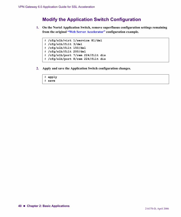
Web Server Accelerator, using Return to Sender (RTS) ...........................................36Modify the NVG Configuration ..........................................................................36Modify the Application Switch Configuration....................................................37
Web Server Accelerator, with NVGs in Non-Transparent Proxy Mode ...................38Modify the NVG Configuration ..........................................................................38Modify the Application Switch Configuration....................................................40
Content-Intelligent Switching for Secure Sessions....................................................41Redundant Active-Standby Configuration.................................................................42
Configure Application Switch 2..........................................................................43Configure Application Switch 1..........................................................................45Verify Failover ....................................................................................................47
Redundant Active-Standby Configuration with NVG Port Failover .........................48Configure Application Switch 1..........................................................................49Configure Application Switch 2..........................................................................50Configure the NVGs............................................................................................50
Mail Server Accelerator .............................................................................................53Initial Setup .........................................................................................................53Configure the NVGs............................................................................................53Configure the Application Switch .......................................................................58Apply and Save the Configuration ......................................................................66
Chapter 3: Web Server Accelerator with End to End Encryption.......... 67Concepts.....................................................................................................................68
SSL Connect........................................................................................................68Connection Pooling .............................................................................................68Load Balancing....................................................................................................69
Configuring End to End Encryption ..........................................................................70Initial Setup of NVGs..........................................................................................70Configure the NVGs............................................................................................70Configure the Application Switch .......................................................................76Verifying End to End Encryption........................................................................81
Chapter 4: Web Server Accelerator with Multiple Networks in Cluster 83Functional Description...............................................................................................85
NVG and Nortel Application Switch ..................................................................85Health Checks......................................................................................................85Trunked Interswitch Connection .........................................................................86
216370-D, April 20064 Contents
VPN Gateway 6.0 Application Guide for SSL Acceleration
Configuring Multiple Networks ................................................................................ 87Initial Setup of NVGs ......................................................................................... 87Configure the NVGs ........................................................................................... 87Configure Application Switch 1 ......................................................................... 97Configure Application Switch 2 ....................................................................... 104On Switch 1, Synchronize the Configuration to Application Switch 2......................................................................................... 107Configure Application Switch 3 ....................................................................... 108Configure Application Switch 4 ....................................................................... 117On Switch 3, Synchronize the Configuration to Application Switch 4......................................................................................... 121
Chapter 5: Configuring the NVG to Rewrite Client Requests .............. 123Setting up Rewrite of Weak Cipher Client Requests .............................................. 123
Chapter 6: HTTP to HTTPS Redirection ................................................. 127Configure HTTP to HTTPS Redirection ................................................................. 127
Application Switch Configuration .................................................................... 129
Chapter 7: Load Balancing of Backend Servers ................................... 131NVG-based Server Load Balancing ........................................................................ 131Metrics for Server Load Balancing ......................................................................... 133
Hash .................................................................................................................. 133Round Robin ..................................................................................................... 133Least Connections ............................................................................................. 134
Health Checks in Server Load Balancing................................................................ 134None .................................................................................................................. 134TCP Health Checks........................................................................................... 135SSL Health Checks ........................................................................................... 135Auto Health Checking....................................................................................... 135Script-Based Health Checking .......................................................................... 135
String Matching in Server Load Balancing ............................................................. 136Persistent Client Connections in Server Load Balancing........................................ 137
Cookie-Based Persistence ................................................................................. 138Configuring Cookie-Based Persistence ............................................................ 141SSL Session-Based Persistence ........................................................................ 149
216370-D, April 2006Contents 5
VPN Gateway 6.0 Application Guide for SSL Acceleration
Chapter 8: String-Based Load Balancing and Blocking....................... 151Creating Match Strings ............................................................................................151
Match String Configuration Examples..............................................................152Additional Match String Options.............................................................................161
Ignore Case in Match.........................................................................................161Negate Result in Match .....................................................................................161
Additional String Load Balancing Options..............................................................162
Chapter 9: Script-Based Health Checks ................................................ 163Customized Health Check Scripts............................................................................164
Script Commands ..............................................................................................164Extended POSIX Regular Expressions .............................................................166Script Configuration Examples .........................................................................167Script Example 1: Health Checking an Auxiliary Server..................................167
Built-In Health Check Scripts ..................................................................................174Verifying Script-Based Health Checks ....................................................................178
Chapter 10: Stand-Alone Web Server Accelerator................................ 179Configuration Example ............................................................................................181
Initial Setup .......................................................................................................181Add a Server Certificate ....................................................................................181Configure the Virtual SSL Server Parameters...................................................182Configure IP Address Migration .......................................................................183Add Load Balancing Support ............................................................................186Directing Traffic to Different SSL Servers .......................................................188Stand-alone Setup Using Two Networks ..........................................................189
Chapter 11: Global Server Load Balancing ........................................... 191Configuration Example ............................................................................................191
Introduction .......................................................................................................191Maintaining cookie persistence .........................................................................192Configuring the Servers at site A and B............................................................193
Glossary.................................................................................................... 201
Index.......................................................................................................... 209
216370-D, April 20066 Contents
Preface
This Application Guide contains example configurations and usage of the Nortel VPN Gate-way (NVG) when using it for SSL acceleration. For instructions on how to deploy the VPN feature, see the Application Guide for VPN (available for both CLI and BBI configuration).
Who Should Use This BookThis Application Guide is intended for network installers and system administrators engaged in configuring and maintaining a network. It assumes that you are familiar with Ethernet concepts and IP addressing. All IP addresses are examples and should not be used as-is.
Related DocumentationFor full documentation on installing, configuring and using the many features of the NVG, see the following manuals:
VPN Gateway 6.0 User’s Guide (part number 216368-D, April 2006)Describes the initial setup procedure, upgrades, operator user management, certificate management, troubleshooting and other general operations that apply to both SSL Accel-eration and VPN.
VPN Gateway 6.0 Command Reference (part number 216369-D April 2006)Describes each command in detail. The commands are listed per menu, according to the order they appear in the Command Line Interface (CLI).
VPN Gateway 6.0 CLI Application Guide for VPN(part number 216371-D April 2006)Provides examples on how to configure VPN deployment via the CLI.
216370-D, April 20067
VPN Gateway 6.0 Application Guide for SSL Acceleration
VPN Gateway 6.0 BBI Application Guide for VPN(part number 217239-C April 2006)Provides examples on how to configure VPN deployment via the BBI (Browser-Based Management Interface).
VPN Gateway 6.0 VPN Administrator’s Guide(part number 217238-C April 2006)VPN management guide intended for end-customers in a Secure Service Partitioning con-figuration.
VPN Gateway 3050/3070 Hardware Installation Guide(part number 216213-B, March 2005)Describes installation of the VPN Gateway 3050 and 3070 hardware models.
VPN Gateway 6.0 Release Notes (part number 216372-G, April 2006)Lists new features available in version 6.0 and provides up-to-date product information.
The above manuals are available for download (see “How to Get Help” on page 11).
Product NamesThe software described in this manual runs on several different hardware models. Whenever the generic terms Nortel VPN Gateway, VPN Gateway or NVG are used in the documentation, the following hardware models are implied:
Nortel VPN Gateway 3050 (NVG 3050)Nortel VPN Gateway 3070 (NVG 3070)Nortel SSL VPN Module 1000 (SVM 1000)Nortel SSL Accelerator 310 (ASA 310)Nortel SSL Accelerator 410 (ASA 410)Nortel SSL Accelerator 310-FIPS (ASA 310-FIPS)The integrated SSL Accelerator (SSL processor) on the Nortel 2424-SSL switch
Similarly, all references to the old product name – iSD-SSL or iSD – in commands or screen outputs should be interpreted as applying to the above hardware models.
NOTE – Manufacturing of the Nortel SSL Accelerator (formerly Alteon SSL Accelerator) has been discontinued.
8 Preface216370-D, April 2006
VPN Gateway 6.0 Application Guide for SSL Acceleration
How This Book Is OrganizedChapter 1, “Public Key Infrastructure and SSL,”provides a general overview of the basic concepts behind Secure Sockets Layer (SSL) transactions in general, as well as the SSL trans-actions involved when the VPN Gateway is used as a web server accelerator.
Chapter 2, “Basic Applications,” provides basic scenarios and configuration examples for using the VPN Gateway for web server acceleration (without end to end encryption), content intelligent switching for secure sessions, and in redundant active-standby configurations.
Chapter 3, “Web Server Accelerator with End to End Encryption,” describes how to con-figure the NVG for end to end encryption, where also the data transmitted between the VPN Gateway and the backend servers is encrypted.
Chapter 4, “Web Server Accelerator with Multiple Networks in Cluster,” describes how to configure multiple networks within a cluster consisting of two VPN Gateways, used in com-bination with four Nortel Application Switches.
Chapter 5, “Configuring the NVG to Rewrite Client Requests,” describes how to configure the VPN Gateway to rewrite client requests for the HTTPS service if the client browser does not meet the required cipher strength.
Chapter 6, “HTTP to HTTPS Redirection,” describes how to configure the VPN Gateway for redirection of http requests to https.
Chapter 7, “Load Balancing of Backend Servers,” describes how to configure the VPN Gateway to perform basic load balancing of real servers. Additional load balancing options such as metrics, health checks, string matching, and persistent client connections are also dis-cussed.
Chapter 8, “String-Based Load Balancing and Blocking,” describes how to create match strings used for load balancing or blocking. Configuration examples with detailed step-by-step instructions are provided in the chapter.
Chapter 9, “Script-Based Health Checks,” describes how to create a customized health check script that can be used when the VPN Gateway is configured to perform load balancing of backend servers.
Chapter 10, “Stand-Alone Web Server Accelerator,” describes how to set up the VPN Gate-way as a stand-alone web server accelerator, without using an Nortel Application Switch.
Chapter 11, “Global Server Load Balancing,” describes how to set up the VPN Gateway for Global server load balancing (GSLB), which allows you to balance server traffic load across multiple physical sites.
Preface 9216370-D, April 2006
VPN Gateway 6.0 Application Guide for SSL Acceleration
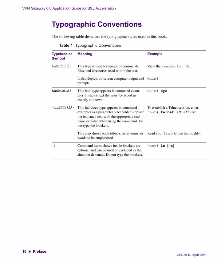
Typographic ConventionsThe following table describes the typographic styles used in this book.
Table 1 Typographic Conventions
Typeface or Symbol
Meaning Example
AaBbCc123 This type is used for names of commands, files, and directories used within the text.
View the readme.txt file.
It also depicts on-screen computer output and prompts.
Main#
AaBbCc123 This bold type appears in command exam-ples. It shows text that must be typed in exactly as shown.
Main# sys
<AaBbCc123> This italicized type appears in command examples as a parameter placeholder. Replace the indicated text with the appropriate real name or value when using the command. Do not type the brackets.
To establish a Telnet session, enter:host# telnet <IP address>
This also shows book titles, special terms, or words to be emphasized.
Read your User’s Guide thoroughly.
[] Command items shown inside brackets are optional and can be used or excluded as the situation demands. Do not type the brackets.
host# ls [-a]
10 Preface216370-D, April 2006
VPN Gateway 6.0 Application Guide for SSL Acceleration
How to Get HelpIf you purchased a service contract for your Nortel product from a distributor or authorized reseller, contact the technical support staff for that distributor or reseller for assistance.
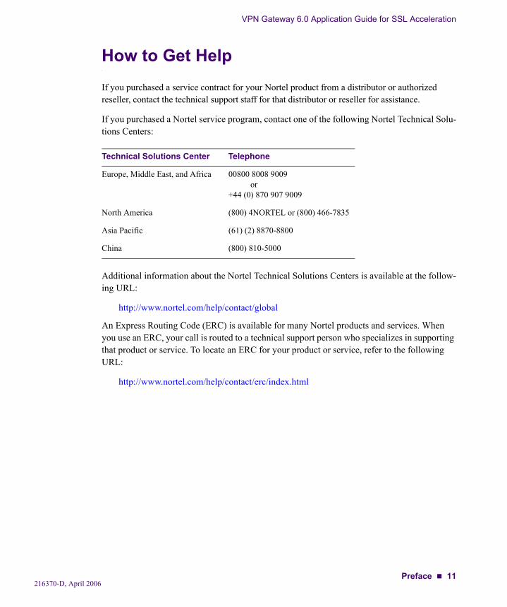
If you purchased a Nortel service program, contact one of the following Nortel Technical Solu-tions Centers:
Additional information about the Nortel Technical Solutions Centers is available at the follow-ing URL:
http://www.nortel.com/help/contact/global
An Express Routing Code (ERC) is available for many Nortel products and services. When you use an ERC, your call is routed to a technical support person who specializes in supporting that product or service. To locate an ERC for your product or service, refer to the following URL:
http://www.nortel.com/help/contact/erc/index.html
Technical Solutions Center Telephone
Europe, Middle East, and Africa 00800 8008 9009or
+44 (0) 870 907 9009
North America (800) 4NORTEL or (800) 466-7835
Asia Pacific (61) (2) 8870-8800
China (800) 810-5000
Preface 11216370-D, April 2006

VPN Gateway 6.0 Application Guide for SSL Acceleration
12 Preface216370-D, April 2006
CHAPTER 1Public Key Infrastructure and SSL
This chapter describes some of the fundamentals behind the Nortel VPN Gateway.
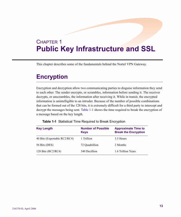
EncryptionEncryption and decryption allow two communicating parties to disguise information they send to each other. The sender encrypts, or scrambles, information before sending it. The receiver decrypts, or unscrambles, the information after receiving it. While in transit, the encrypted information is unintelligible to an intruder. Because of the number of possible combinations that can be formed out of the 128 bits, it is extremely difficult for a third party to intercept and decrypt the messages being sent. Table 1-1 shows the time required to break the encryption of a message based on the key length.
Table 1-1 Statistical Time Required to Break Encryption
Key Length Number of Possible Keys
Approximate Time to Break the Encryption
40 Bits (Exportable RC2/RC4) 1 Trillion 3.5 Hours
56 Bits (DES) 72 Quadrillion 2 Months
128 Bits (RC2/RC4) 340 Decillion 1.6 Trillion Years
216370-D, April 200613
VPN Gateway 6.0 Application Guide for SSL Acceleration
Public Key EncryptionPublic key encryption (also called asymmetric encryption) involves a pair of keys—a public key and a private key—associated with an entity that needs to authenticate its identity electron-ically or to sign or encrypt data. Each public key is published, and the corresponding private key is kept secret. Data encrypted with your public key can be decrypted only with your pri-vate key.
Public key cryptography facilitates the following tasks:
Tamper detection allows the recipient of information to verify that it has not been modi-fied in transit. Any attempt to modify data or substitute a false message will be detected.
Authentication allows the recipient of information to determine its origin— that is, to con-firm the sender's identity.
Non-repudiation prevents the sender of information from later claiming that the informa-tion was never sent.
Digital SignaturesIt is possible to use a private key for encryption and a public key for decryption. Although this is not desirable when encrypting sensitive information, it is a crucial part of digitally signing any data. Instead of encrypting the data itself, the signing software creates a one-way hash of the data and then uses a private key to encrypt the hash. The encrypted hash, along with other information, such as the hashing algorithm, is known as a digital signature.
When sending encrypted messages using public key encryption, digital signatures are used to ensure that the message originated with the person sending it, and that the message was not tampered with after the signature was applied.
Digital signatures are also used in digital certificates, where the certificate owner’s public key is digitally signed with the private key of a certificate authority. A server certificate, along with other data, is sent to the client during the SSL handshake. The client then uses this information, along with the public key of the certificate authority, in order to authenticate the server.
216370-D, April 200614 Chapter 1: Public Key Infrastructure and SSL
VPN Gateway 6.0 Application Guide for SSL Acceleration
CertificatesA certificate is an electronic document used to identify an individual, a server, a company, or some other entity and to associate that identity with a public key. A certificate provides recog-nized proof of a person's identity. Public key cryptography uses certificates to address the problem of impersonation. There are two kinds of certificates:
Register Certificates: certificates that have been authenticated by an authenticating ser-vice, such as a certificate authority.
Chain Certificates: certificates that have been authenticated by other certificates that have been authenticated by an authenticating service.
Certificate AuthoritiesA certificate authority (CA) is an entity that validates identities and issues certificates. They are issued by either independent third parties or independent organizations operating their own certificate-issuing server software (such as Netscape Certificate Server). The methods used to validate an identity vary, depending on the policies of a given CA. In general, before issuing a certificate, the CA must use its published verification procedures for that type of certificate to ensure that an entity requesting a certificate is authentic.
Register CertificatesThe certificate issued by the CA binds a particular public key to the name of the entity that the certificate identifies (such as the name of an employee or a server). Certificates help prevent the use of fake public keys for impersonation.
In addition to a public key, a certificate always includes the name of the entity it identifies, an expiration date, the name of the CA that issued the certificate, a serial number, and other infor-mation. Most importantly, a certificate always includes the digital signature of the issuing CA. The digital signature of the issuing CA allows the certificate to function as a “letter of intro-duction” for users who know and trust the CA.
Chain CertificatesChain certificate allows a chain of trust to be created. Each certificate in the chain attests to the identity of the previous certificate. The final certificate will be a certificate that has been authenticated by a trusted CA. For example, client A trusts the CA, and the CA trusts client B, therefore, client A trusts client B.
216370-D, April 2006Chapter 1: Public Key Infrastructure and SSL 15
VPN Gateway 6.0 Application Guide for SSL Acceleration
Secure Sockets Layer (SSL)The Secure Sockets Layer (SSL) protocol runs above the TCP/IP protocol and below higher-level protocols such as HTTP or IMAP. SSL uses TCP/IP on behalf of the higher-level protocols and, in the process, allows an SSL-enabled server to authenticate itself to an SSL-enabled client. The client then authenticates itself to the server, and both machines establish an encrypted connection. The current standard is TLS (Transport Layer Security) but the name SSL is still kept.
Example of an SSL TransactionThe steps involved in an SSL transaction can be done with a VPN Gateway (or an SSL-enabled server). The steps are summarized as follows:
1. The client sends the following information to the VPN Gateway: SSL version number, cipher settings, randomly generated data, and other information that the server needs to communicate with the SSL client.
2. The VPN Gateway sends the following information to the client: SSL version number, cipher settings, randomly generated data, and other information needed to communicate with the server over SSL. The server also sends its own certificate and, if the client is requesting a server resource that requires client authentication, requests the client's certificate.
3. The client uses some of the information sent by the VPN Gateway to authenticate it. If the VPN Gateway is not authenticated, the user is warned of the problem and informed that an encrypted and authenticated connection cannot be established. If the VPN Gateway is success-fully authenticated, the client goes on to Step 4.
4. The client (with the cooperation of the VPN Gateway, depending on the cipher being used) creates the premaster secret for the session, encrypts it with the NVG’s public key (obtained from the NVG’s certificate, sent in Step 2), and sends the encrypted premaster secret to the VPN Gateway.
5. If the VPN Gateway has requested client authentication (an optional step in the handshake), the client also signs another piece of data that is unique to this handshake and is known by both the client and the VPN Gateway. In this case the client sends both the signed data and the cli-ent's own certificate to the NVG along with the encrypted premaster secret.
216370-D, April 200616 Chapter 1: Public Key Infrastructure and SSL
VPN Gateway 6.0 Application Guide for SSL Acceleration
6. If the VPN Gateway has requested client authentication, it attempts to authenticate the client. If the client is not authenticated, the session is terminated. If the client can be successfully authenticated, the VPN Gateway uses its private key to decrypt the premaster secret, then per-forms a series of steps (which the client also performs, starting from the same premaster secret) to generate the master secret.
7. Both the client and the VPN Gateway use the master secret to generate the session key, which is a symmetric key. It is used to encrypt and decrypt information exchanged during the SSL session and to verify its integrity—that is, to detect any change in the data between the time it was sent and the time it is received over the SSL connection.
8. The client informs the VPN Gateway that future messages from the client will be encrypted with the session key. The client then sends a separate (encrypted) message indicating that the client portion of the handshake is finished.
9. The VPN Gateway informs the client that future messages will be encrypted with the session key. It then sends the client a separate (encrypted) message indicating that the NVG portion of the handshake is finished.
10. The SSL handshake is now complete, and the SSL session begins. The client and the VPN Gateway use the session keys to encrypt and decrypt the data they send to each other and to verify data integrity.
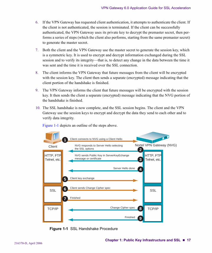
Figure 1-1 depicts an outline of the steps above.
Figure 1-1 SSL Handshake Procedure
Client connects to NVG using a Client Hello
NVG responds to Server Hello selectingthe SSL options
NVG sends Public Key in ServerKeyEchangemessage or certificate
Server Hello done
Client sends Change Cipher spec
Change Cipher spec
Client key exchange
Finished
Finished
Client Nortel VPN Gateway (NVG)
1
2
3
4
5
6
7
8
9
HTTP, FTPTelnet, etc.
SSL
TCP/IP
HTTP, FTPTelnet, etc.
SSL
TCP/IP
216370-D, April 2006Chapter 1: Public Key Infrastructure and SSL 17
VPN Gateway 6.0 Application Guide for SSL Acceleration
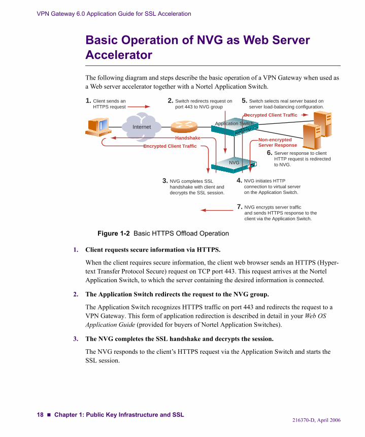
Basic Operation of NVG as Web Server AcceleratorThe following diagram and steps describe the basic operation of a VPN Gateway when used as a Web server accelerator together with a Nortel Application Switch.
Figure 1-2 Basic HTTPS Offload Operation
1. Client requests secure information via HTTPS.
When the client requires secure information, the client web browser sends an HTTPS (Hyper-text Transfer Protocol Secure) request on TCP port 443. This request arrives at the Nortel Application Switch, to which the server containing the desired information is connected.
2. The Application Switch redirects the request to the NVG group.
The Application Switch recognizes HTTPS traffic on port 443 and redirects the request to a VPN Gateway. This form of application redirection is described in detail in your Web OS Application Guide (provided for buyers of Nortel Application Switches).
3. The NVG completes the SSL handshake and decrypts the session.
The NVG responds to the client’s HTTPS request via the Application Switch and starts the SSL session.
Client sends anHTTPS request
1. Switch redirects request onport 443 to NVG group
2.
NVG completes SSLhandshake with client anddecrypts the SSL session.
3. NVG initiates HTTPconnection to virtual serveron the Application Switch.
4.
InternetApplication Switch
NVG
Encrypted Client Traffic
Handshake
NVG encrypts server trafficand sends HTTPS response to theclient via the Application Switch.
7.
Switch selects real server based onserver load-balancing configuration.
5.
Server response to clientHTTP request is redirected
to NVG.
6.
Decrypted Client Traffic
Non-encryptedServer Response
216370-D, April 200618 Chapter 1: Public Key Infrastructure and SSL

VPN Gateway 6.0 Application Guide for SSL Acceleration
4. The NVG initiates HTTP connection to the virtual server.
The NVG receives the client’s encrypted SSL traffic via the Application Switch. The NVG decrypts the secure traffic and forwards it as a regular HTTP request to a virtual server on the Application Switch.
5. The Application Switch selects a real server based on configured load-balancing options.
Based on criteria such as server health status and configured load-balancing distribution met-rics, the Application Switch selects a real server and forwards the client’s decrypted HTTP traffic.
6. The server processes the HTTP request and replies to the client.
The server sends the requested non-encrypted HTTP information intended for the client’s IP address. The Application Switch redirects this traffic to the VPN Gateway.
7. The NVG encrypts the server traffic and sends the HTTPS response to the client via the Application Switch.
216370-D, April 2006Chapter 1: Public Key Infrastructure and SSL 19
VPN Gateway 6.0 Application Guide for SSL Acceleration
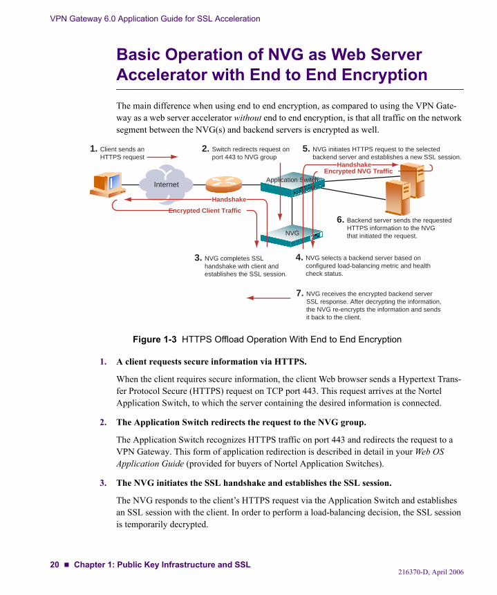
Basic Operation of NVG as Web Server Accelerator with End to End EncryptionThe main difference when using end to end encryption, as compared to using the VPN Gate-way as a web server accelerator without end to end encryption, is that all traffic on the network segment between the NVG(s) and backend servers is encrypted as well.
Figure 1-3 HTTPS Offload Operation With End to End Encryption
1. A client requests secure information via HTTPS.
When the client requires secure information, the client Web browser sends a Hypertext Trans-fer Protocol Secure (HTTPS) request on TCP port 443. This request arrives at the Nortel Application Switch, to which the server containing the desired information is connected.
2. The Application Switch redirects the request to the NVG group.
The Application Switch recognizes HTTPS traffic on port 443 and redirects the request to a VPN Gateway. This form of application redirection is described in detail in your Web OS Application Guide (provided for buyers of Nortel Application Switches).
3. The NVG initiates the SSL handshake and establishes the SSL session.
The NVG responds to the client’s HTTPS request via the Application Switch and establishes an SSL session with the client. In order to perform a load-balancing decision, the SSL session is temporarily decrypted.
Client sends anHTTPS request
1. Switch redirects request onport 443 to NVG group
2.
NVG completes SSLhandshake with client andestablishes the SSL session.
3. NVG selects a backend server based onconfigured load-balancing metric and healthcheck status.
4.
InternetApplication Switch
NVG
Encrypted Client Traffic
Handshake
NVG receives the encrypted backend serverSSL response. After decrypting the information,the NVG re-encrypts the information and sendsit back to the client.
7.
NVG initiates HTTPS request to the selectedbackend server and establishes a new SSL session.
5.
Backend server sends the requestedHTTPS information to the NVG that initiated the request.
6.
HandshakeEncrypted NVG Traffic
216370-D, April 200620 Chapter 1: Public Key Infrastructure and SSL
VPN Gateway 6.0 Application Guide for SSL Acceleration
4. The NVG selects a backend server based on the configured load-balancing options and health check status.
Based on criteria such as backend server health check status and configured load-balancing distribution metrics, the NVG selects a backend server.
5. The NVG establishes an SSL connection to the selected backend server.
After having re-encrypted the client’s request, the NVG initiates an HTTPS request over an SSL connection to the selected backend server on behalf of the client. On subsequent requests, the NVG will always reuse an existing SSL session in order to decrease the overhead involved in performing a full SSL handshake.
6. The backend server processes the HTTPS request and replies to the NVG.
The backend server sends the requested encrypted HTTPS information to the NVG that initi-ated the request.
7. The NVG receives the backend server traffic and sends the HTTPS response to the client via the Nortel Application Switch.
The NVG receives the backend server’s encrypted SSL traffic via the Application Switch. After decrypting the response from the backend server, the NVG re-encrypts the information using the initial encryption algorithm, and sends it back to the client.
216370-D, April 2006Chapter 1: Public Key Infrastructure and SSL 21

VPN Gateway 6.0 Application Guide for SSL Acceleration
216370-D, April 200622 Chapter 1: Public Key Infrastructure and SSL

CHAPTER 2Basic Applications
This chapter describes some basic network applications that make use of the VPN Gateway:
Web Server Accelerator, using a Nortel Application Switch configured with redirect fil-ters, and two or more load-balanced VPN Gateways for SSL offload configured to run in transparent proxy mode, on page 24.
Web Server Accelerator, using a Nortel Application Switch configured to use the Return To Sender feature, and two or more load-balanced VPN Gateways for SSL offload config-ured to run in transparent proxy mode, on page 36.
Web Server Accelerator, using two or more load-balanced VPN Gateways for SSL off-load, and where the NVGs are configured to run in non-transparent proxy mode, on page 38.
Content-Intelligent Switching for Secure Sessions, using single or multiple VPN Gate-ways for SSL offload with cookie processing, on page 41.
Redundant Active-Standby Configuration, using multiple VPN Gateways for high-avail-ability scenarios, on page 42.
Mail Server Accelerator, using two or more load-balanced VPN Gateways for SSL off-load, on page 53.
The sample configurations discussed are merely recommendations and are not required. The first five examples are based on the configuration described in “Web Server Accelera-tor” on page 24. Therefore, it is recommended that you read this chapter in sequence, and modify the base configuration as noted in each subsequent example.
In the Mail Server Accelerator example it is assumed that Web server acceleration has not been set up. However, it is possible to use mail server acceleration in parallel with Web server accel-erating using the same group of NVGs.
216370-D, April 200623
VPN Gateway 6.0 Application Guide for SSL Acceleration
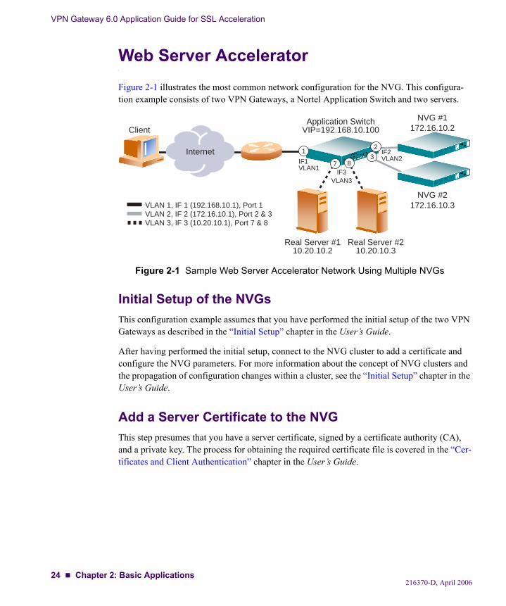
Web Server AcceleratorFigure 2-1 illustrates the most common network configuration for the NVG. This configura-tion example consists of two VPN Gateways, a Nortel Application Switch and two servers.
Figure 2-1 Sample Web Server Accelerator Network Using Multiple NVGs
Initial Setup of the NVGsThis configuration example assumes that you have performed the initial setup of the two VPN Gateways as described in the “Initial Setup” chapter in the User’s Guide.
After having performed the initial setup, connect to the NVG cluster to add a certificate and configure the NVG parameters. For more information about the concept of NVG clusters and the propagation of configuration changes within a cluster, see the “Initial Setup” chapter in the User’s Guide.
Add a Server Certificate to the NVGThis step presumes that you have a server certificate, signed by a certificate authority (CA), and a private key. The process for obtaining the required certificate file is covered in the “Cer-tificates and Client Authentication” chapter in the User’s Guide.
Internet
ClientApplication Switch
VIP=192.168.10.100
Real Server #110.20.10.2
Real Server #210.20.10.3
13
2
87
NVG #1172.16.10.2
NVG #2172.16.10.3
IF3VLAN3
IF2VLAN2IF1
VLAN1
VLAN 1, IF 1 (192.168.10.1), Port 1VLAN 2, IF 2 (172.16.10.1), Port 2 & 3VLAN 3, IF 3 (10.20.10.1), Port 7 & 8
216370-D, April 200624 Chapter 2: Basic Applications
VPN Gateway 6.0 Application Guide for SSL Acceleration
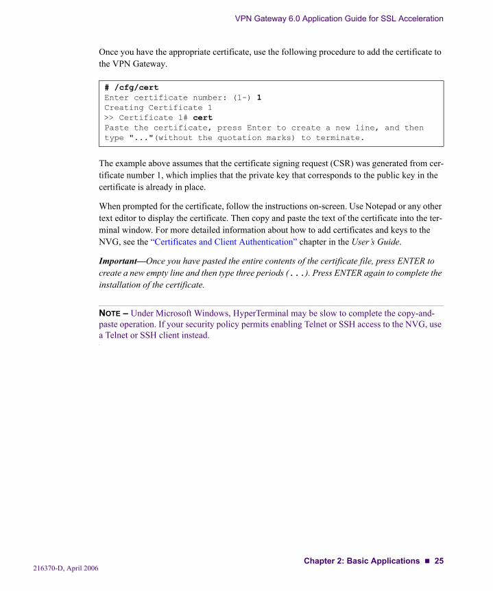
Once you have the appropriate certificate, use the following procedure to add the certificate to the VPN Gateway.
The example above assumes that the certificate signing request (CSR) was generated from cer-tificate number 1, which implies that the private key that corresponds to the public key in the certificate is already in place.
When prompted for the certificate, follow the instructions on-screen. Use Notepad or any other text editor to display the certificate. Then copy and paste the text of the certificate into the ter-minal window. For more detailed information about how to add certificates and keys to the NVG, see the “Certificates and Client Authentication” chapter in the User’s Guide.
Important—Once you have pasted the entire contents of the certificate file, press ENTER to create a new empty line and then type three periods (...). Press ENTER again to complete the installation of the certificate.
NOTE – Under Microsoft Windows, HyperTerminal may be slow to complete the copy-and-paste operation. If your security policy permits enabling Telnet or SSH access to the NVG, use a Telnet or SSH client instead.
# /cfg/certEnter certificate number: (1-) 1Creating Certificate 1>> Certificate 1# certPaste the certificate, press Enter to create a new line, and then type "..."(without the quotation marks) to terminate.
216370-D, April 2006Chapter 2: Basic Applications 25
VPN Gateway 6.0 Application Guide for SSL Acceleration
Configure the VPN GatewaysThe configuration changes will automatically be propagated to all VPN Gateways in the clus-ter.
Create and Configure a Virtual SSL Server
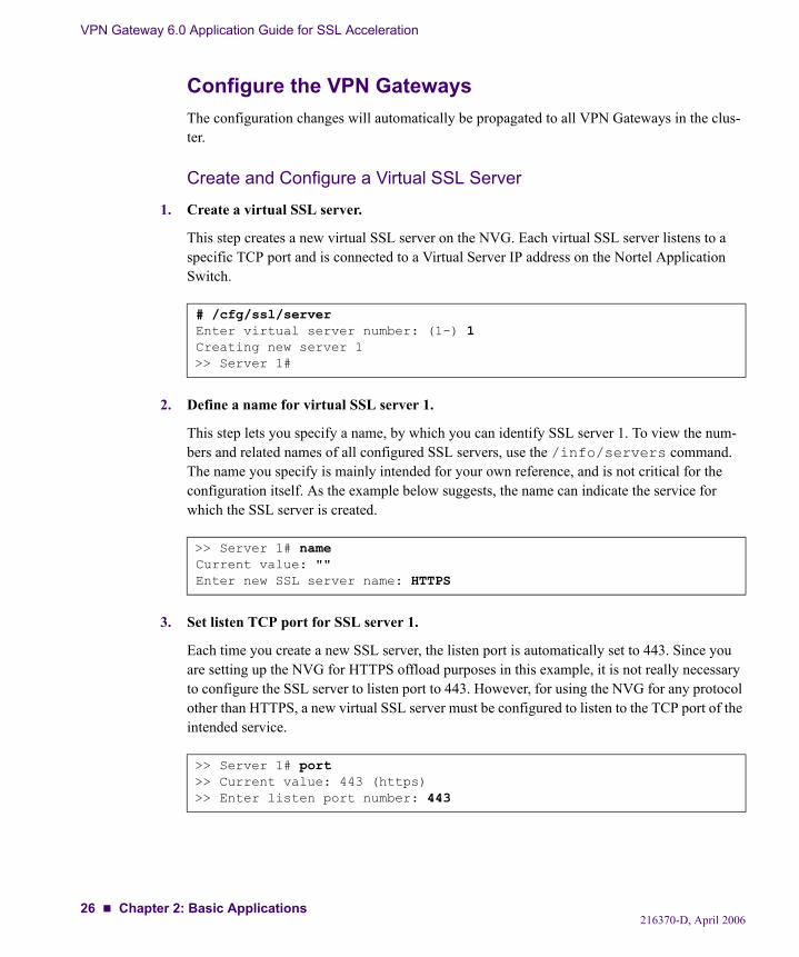
1. Create a virtual SSL server.
This step creates a new virtual SSL server on the NVG. Each virtual SSL server listens to a specific TCP port and is connected to a Virtual Server IP address on the Nortel Application Switch.
2. Define a name for virtual SSL server 1.
This step lets you specify a name, by which you can identify SSL server 1. To view the num-bers and related names of all configured SSL servers, use the /info/servers command. The name you specify is mainly intended for your own reference, and is not critical for the configuration itself. As the example below suggests, the name can indicate the service for which the SSL server is created.
3. Set listen TCP port for SSL server 1.
Each time you create a new SSL server, the listen port is automatically set to 443. Since you are setting up the NVG for HTTPS offload purposes in this example, it is not really necessary to configure the SSL server to listen port to 443. However, for using the NVG for any protocol other than HTTPS, a new virtual SSL server must be configured to listen to the TCP port of the intended service.
# /cfg/ssl/serverEnter virtual server number: (1-) 1Creating new server 1>> Server 1#
>> Server 1# nameCurrent value: ""Enter new SSL server name: HTTPS
>> Server 1# port>> Current value: 443 (https)>> Enter listen port number: 443
216370-D, April 200626 Chapter 2: Basic Applications
VPN Gateway 6.0 Application Guide for SSL Acceleration
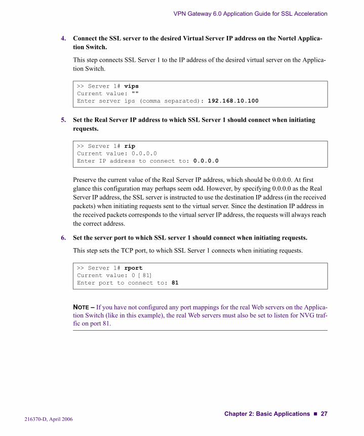
4. Connect the SSL server to the desired Virtual Server IP address on the Nortel Applica-tion Switch.
This step connects SSL Server 1 to the IP address of the desired virtual server on the Applica-tion Switch.
5. Set the Real Server IP address to which SSL Server 1 should connect when initiating requests.
Preserve the current value of the Real Server IP address, which should be 0.0.0.0. At first glance this configuration may perhaps seem odd. However, by specifying 0.0.0.0 as the Real Server IP address, the SSL server is instructed to use the destination IP address (in the received packets) when initiating requests sent to the virtual server. Since the destination IP address in the received packets corresponds to the virtual server IP address, the requests will always reach the correct address.
6. Set the server port to which SSL server 1 should connect when initiating requests.
This step sets the TCP port, to which SSL Server 1 connects when initiating requests.
NOTE – If you have not configured any port mappings for the real Web servers on the Applica-tion Switch (like in this example), the real Web servers must also be set to listen for NVG traf-fic on port 81.
>> Server 1# vipsCurrent value: ""Enter server ips (comma separated): 192.168.10.100
>> Server 1# ripCurrent value: 0.0.0.0Enter IP address to connect to: 0.0.0.0
>> Server 1# rportCurrent value: 0 [81]Enter port to connect to: 81
216370-D, April 2006Chapter 2: Basic Applications 27

VPN Gateway 6.0 Application Guide for SSL Acceleration
7. Specify the certificate to be used by SSL Server 1.
You are prompted to type the index number of an existing certificate. To view all certificates currently added to the NVG by index number and name, use the /info/certs command. For more information on how to add a certificate to the NVG, see the “Certificates and Client Authentication” chapter in the User’s Guide.
NOTE – If the certificate you specify is a chained certificate, you need to first add the CA cer-tificates up to and including the root CA certificate, and then specify the CA certificate chain of the server certificate. For more information on how to construct the server certificate chain, see the cachain command under “SSL Server SSL Configuration” in the Command Refer-ence.
8. Apply the changes.
>> Server 1# ssl>> SSL Settings for server 1# certCurrent value: <not set>Enter certificate number: (1-) 1
>> SSL Settings for Server 1# applyChanges applied successfully.
216370-D, April 200628 Chapter 2: Basic Applications
VPN Gateway 6.0 Application Guide for SSL Acceleration
Configure the Nortel Application Switch
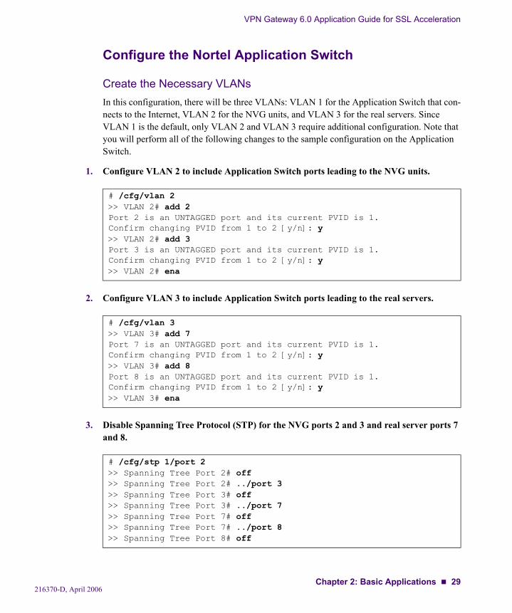
Create the Necessary VLANsIn this configuration, there will be three VLANs: VLAN 1 for the Application Switch that con-nects to the Internet, VLAN 2 for the NVG units, and VLAN 3 for the real servers. Since VLAN 1 is the default, only VLAN 2 and VLAN 3 require additional configuration. Note that you will perform all of the following changes to the sample configuration on the Application Switch.
1. Configure VLAN 2 to include Application Switch ports leading to the NVG units.
2. Configure VLAN 3 to include Application Switch ports leading to the real servers.
3. Disable Spanning Tree Protocol (STP) for the NVG ports 2 and 3 and real server ports 7 and 8.
# /cfg/vlan 2>> VLAN 2# add 2Port 2 is an UNTAGGED port and its current PVID is 1.Confirm changing PVID from 1 to 2 [y/n]: y>> VLAN 2# add 3Port 3 is an UNTAGGED port and its current PVID is 1.Confirm changing PVID from 1 to 2 [y/n]: y>> VLAN 2# ena
# /cfg/vlan 3>> VLAN 3# add 7Port 7 is an UNTAGGED port and its current PVID is 1.Confirm changing PVID from 1 to 2 [y/n]: y>> VLAN 3# add 8Port 8 is an UNTAGGED port and its current PVID is 1.Confirm changing PVID from 1 to 2 [y/n]: y>> VLAN 3# ena
# /cfg/stp 1/port 2>> Spanning Tree Port 2# off>> Spanning Tree Port 2# ../port 3>> Spanning Tree Port 3# off>> Spanning Tree Port 3# ../port 7>> Spanning Tree Port 7# off>> Spanning Tree Port 7# ../port 8>> Spanning Tree Port 8# off
216370-D, April 2006Chapter 2: Basic Applications 29
VPN Gateway 6.0 Application Guide for SSL Acceleration
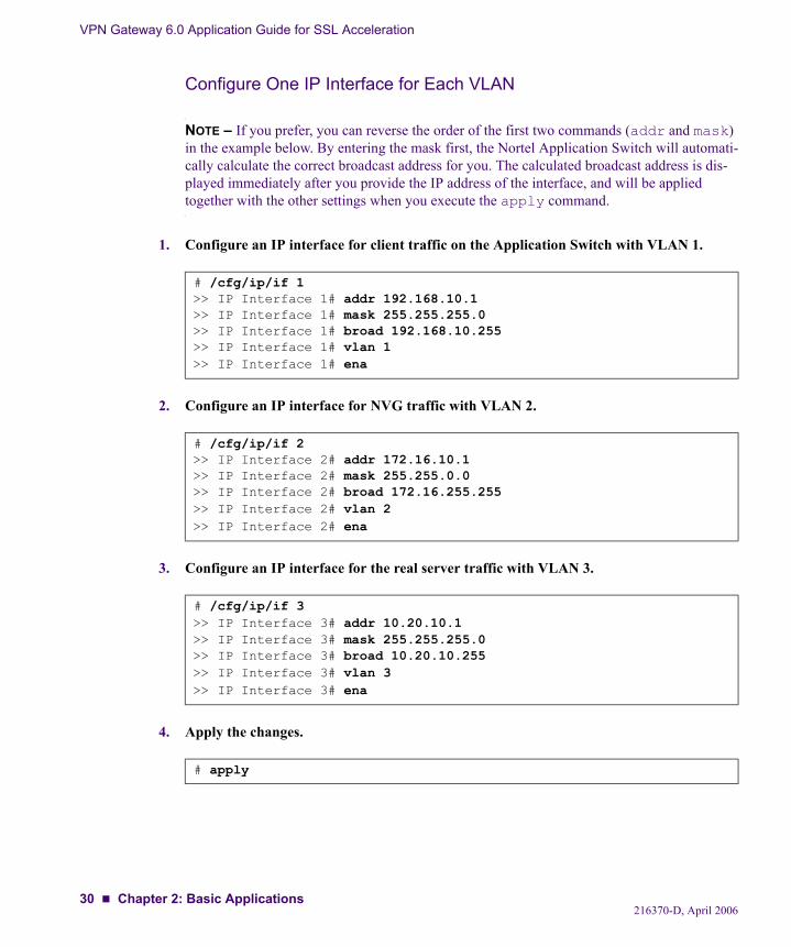
Configure One IP Interface for Each VLAN
NOTE – If you prefer, you can reverse the order of the first two commands (addr and mask) in the example below. By entering the mask first, the Nortel Application Switch will automati-cally calculate the correct broadcast address for you. The calculated broadcast address is dis-played immediately after you provide the IP address of the interface, and will be applied together with the other settings when you execute the apply command.
1. Configure an IP interface for client traffic on the Application Switch with VLAN 1.
2. Configure an IP interface for NVG traffic with VLAN 2.
3. Configure an IP interface for the real server traffic with VLAN 3.
4. Apply the changes.
# /cfg/ip/if 1>> IP Interface 1# addr 192.168.10.1>> IP Interface 1# mask 255.255.255.0>> IP Interface 1# broad 192.168.10.255>> IP Interface 1# vlan 1>> IP Interface 1# ena
# /cfg/ip/if 2>> IP Interface 2# addr 172.16.10.1>> IP Interface 2# mask 255.255.0.0>> IP Interface 2# broad 172.16.255.255>> IP Interface 2# vlan 2>> IP Interface 2# ena
# /cfg/ip/if 3>> IP Interface 3# addr 10.20.10.1>> IP Interface 3# mask 255.255.255.0>> IP Interface 3# broad 10.20.10.255>> IP Interface 3# vlan 3>> IP Interface 3# ena
# apply
216370-D, April 200630 Chapter 2: Basic Applications
VPN Gateway 6.0 Application Guide for SSL Acceleration
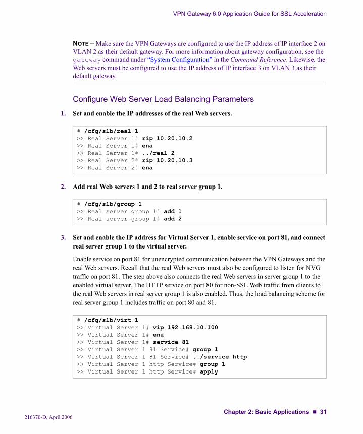
NOTE – Make sure the VPN Gateways are configured to use the IP address of IP interface 2 on VLAN 2 as their default gateway. For more information about gateway configuration, see the gateway command under “System Configuration” in the Command Reference. Likewise, the Web servers must be configured to use the IP address of IP interface 3 on VLAN 3 as their default gateway.
Configure Web Server Load Balancing Parameters
1. Set and enable the IP addresses of the real Web servers.
2. Add real Web servers 1 and 2 to real server group 1.
3. Set and enable the IP address for Virtual Server 1, enable service on port 81, and connect real server group 1 to the virtual server.
Enable service on port 81 for unencrypted communication between the VPN Gateways and the real Web servers. Recall that the real Web servers must also be configured to listen for NVG traffic on port 81. The step above also connects the real Web servers in server group 1 to the enabled virtual server. The HTTP service on port 80 for non-SSL Web traffic from clients to the real Web servers in real server group 1 is also enabled. Thus, the load balancing scheme for real server group 1 includes traffic on port 80 and 81.
# /cfg/slb/real 1>> Real Server 1# rip 10.20.10.2>> Real Server 1# ena>> Real Server 1# ../real 2>> Real Server 2# rip 10.20.10.3>> Real Server 2# ena
# /cfg/slb/group 1>> Real server group 1# add 1>> Real server group 1# add 2
# /cfg/slb/virt 1>> Virtual Server 1# vip 192.168.10.100>> Virtual Server 1# ena>> Virtual Server 1# service 81>> Virtual Server 1 81 Service# group 1>> Virtual Server 1 81 Service# ../service http>> Virtual Server 1 http Service# group 1>> Virtual Server 1 http Service# apply
216370-D, April 2006Chapter 2: Basic Applications 31
VPN Gateway 6.0 Application Guide for SSL Acceleration
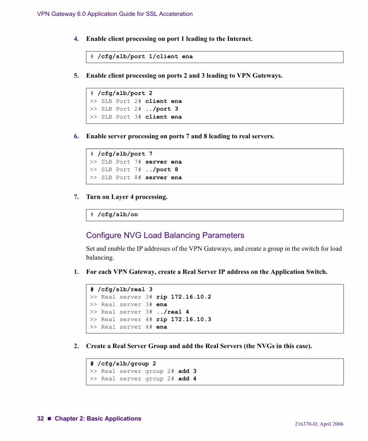
4. Enable client processing on port 1 leading to the Internet.
5. Enable client processing on ports 2 and 3 leading to VPN Gateways.
6. Enable server processing on ports 7 and 8 leading to real servers.
7. Turn on Layer 4 processing.
Configure NVG Load Balancing ParametersSet and enable the IP addresses of the VPN Gateways, and create a group in the switch for load balancing.
1. For each VPN Gateway, create a Real Server IP address on the Application Switch.
2. Create a Real Server Group and add the Real Servers (the NVGs in this case).
# /cfg/slb/port 1/client ena
# /cfg/slb/port 2>> SLB Port 2# client ena>> SLB Port 2# ../port 3>> SLB Port 3# client ena
# /cfg/slb/port 7>> SLB Port 7# server ena>> SLB Port 7# ../port 8>> SLB Port 8# server ena
# /cfg/slb/on
# /cfg/slb/real 3>> Real server 3# rip 172.16.10.2>> Real server 3# ena>> Real server 3# ../real 4>> Real server 4# rip 172.16.10.3>> Real server 4# ena
# /cfg/slb/group 2>> Real server group 2# add 3>> Real server group 2# add 4
216370-D, April 200632 Chapter 2: Basic Applications
VPN Gateway 6.0 Application Guide for SSL Acceleration
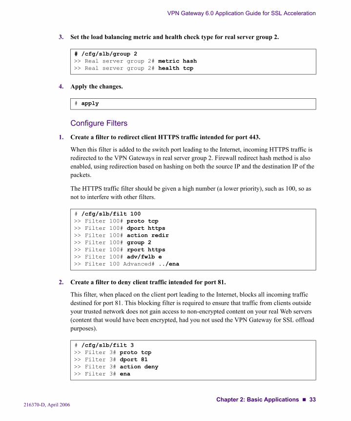
3. Set the load balancing metric and health check type for real server group 2.
4. Apply the changes.
Configure Filters
1. Create a filter to redirect client HTTPS traffic intended for port 443.
When this filter is added to the switch port leading to the Internet, incoming HTTPS traffic is redirected to the VPN Gateways in real server group 2. Firewall redirect hash method is also enabled, using redirection based on hashing on both the source IP and the destination IP of the packets.
The HTTPS traffic filter should be given a high number (a lower priority), such as 100, so as not to interfere with other filters.
2. Create a filter to deny client traffic intended for port 81.
This filter, when placed on the client port leading to the Internet, blocks all incoming traffic destined for port 81. This blocking filter is required to ensure that traffic from clients outside your trusted network does not gain access to non-encrypted content on your real Web servers (content that would have been encrypted, had you not used the VPN Gateway for SSL offload purposes).
# /cfg/slb/group 2>> Real server group 2# metric hash>> Real server group 2# health tcp
# apply
# /cfg/slb/filt 100>> Filter 100# proto tcp>> Filter 100# dport https>> Filter 100# action redir>> Filter 100# group 2>> Filter 100# rport https>> Filter 100# adv/fwlb e>> Filter 100 Advanced# ../ena
# /cfg/slb/filt 3>> Filter 3# proto tcp>> Filter 3# dport 81>> Filter 3# action deny>> Filter 3# ena
216370-D, April 2006Chapter 2: Basic Applications 33
VPN Gateway 6.0 Application Guide for SSL Acceleration
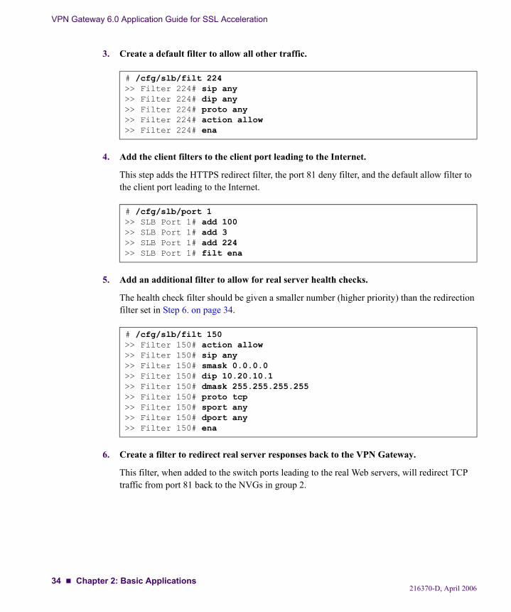
3. Create a default filter to allow all other traffic.
4. Add the client filters to the client port leading to the Internet.
This step adds the HTTPS redirect filter, the port 81 deny filter, and the default allow filter to the client port leading to the Internet.
5. Add an additional filter to allow for real server health checks.
The health check filter should be given a smaller number (higher priority) than the redirection filter set in Step 6. on page 34.
6. Create a filter to redirect real server responses back to the VPN Gateway.
This filter, when added to the switch ports leading to the real Web servers, will redirect TCP traffic from port 81 back to the NVGs in group 2.
# /cfg/slb/filt 224>> Filter 224# sip any>> Filter 224# dip any>> Filter 224# proto any>> Filter 224# action allow>> Filter 224# ena
# /cfg/slb/port 1>> SLB Port 1# add 100>> SLB Port 1# add 3>> SLB Port 1# add 224>> SLB Port 1# filt ena
# /cfg/slb/filt 150>> Filter 150# action allow>> Filter 150# sip any>> Filter 150# smask 0.0.0.0>> Filter 150# dip 10.20.10.1>> Filter 150# dmask 255.255.255.255>> Filter 150# proto tcp>> Filter 150# sport any>> Filter 150# dport any>> Filter 150# ena
216370-D, April 200634 Chapter 2: Basic Applications
VPN Gateway 6.0 Application Guide for SSL Acceleration
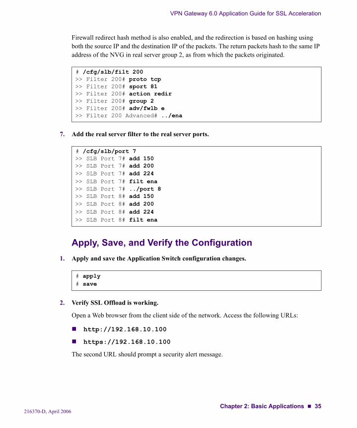
Firewall redirect hash method is also enabled, and the redirection is based on hashing using both the source IP and the destination IP of the packets. The return packets hash to the same IP address of the NVG in real server group 2, as from which the packets originated.
7. Add the real server filter to the real server ports.
Apply, Save, and Verify the Configuration1. Apply and save the Application Switch configuration changes.
2. Verify SSL Offload is working.
Open a Web browser from the client side of the network. Access the following URLs:
http://192.168.10.100
https://192.168.10.100
The second URL should prompt a security alert message.
# /cfg/slb/filt 200>> Filter 200# proto tcp>> Filter 200# sport 81>> Filter 200# action redir>> Filter 200# group 2>> Filter 200# adv/fwlb e>> Filter 200 Advanced# ../ena
# /cfg/slb/port 7>> SLB Port 7# add 150>> SLB Port 7# add 200>> SLB Port 7# add 224>> SLB Port 7# filt ena>> SLB Port 7# ../port 8>> SLB Port 8# add 150>> SLB Port 8# add 200>> SLB Port 8# add 224>> SLB Port 8# filt ena
# apply# save
216370-D, April 2006Chapter 2: Basic Applications 35
VPN Gateway 6.0 Application Guide for SSL Acceleration
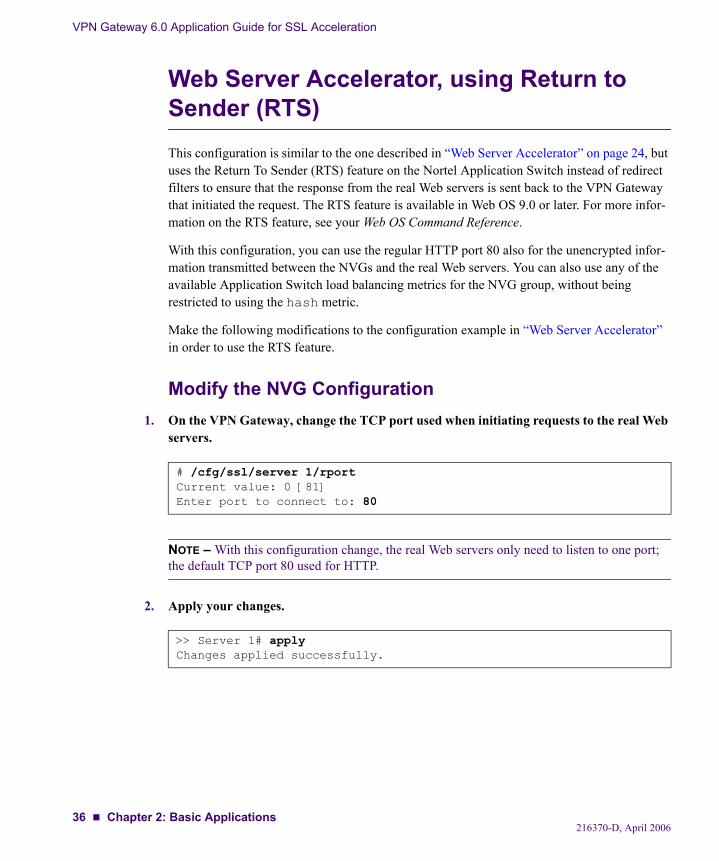
Web Server Accelerator, using Return to Sender (RTS)This configuration is similar to the one described in “Web Server Accelerator” on page 24, but uses the Return To Sender (RTS) feature on the Nortel Application Switch instead of redirect filters to ensure that the response from the real Web servers is sent back to the VPN Gateway that initiated the request. The RTS feature is available in Web OS 9.0 or later. For more infor-mation on the RTS feature, see your Web OS Command Reference.
With this configuration, you can use the regular HTTP port 80 also for the unencrypted infor-mation transmitted between the NVGs and the real Web servers. You can also use any of the available Application Switch load balancing metrics for the NVG group, without being restricted to using the hash metric.
Make the following modifications to the configuration example in “Web Server Accelerator” in order to use the RTS feature.
Modify the NVG Configuration1. On the VPN Gateway, change the TCP port used when initiating requests to the real Web
servers.
NOTE – With this configuration change, the real Web servers only need to listen to one port; the default TCP port 80 used for HTTP.
2. Apply your changes.
# /cfg/ssl/server 1/rportCurrent value: 0 [81]Enter port to connect to: 80
>> Server 1# applyChanges applied successfully.
216370-D, April 200636 Chapter 2: Basic Applications
VPN Gateway 6.0 Application Guide for SSL Acceleration
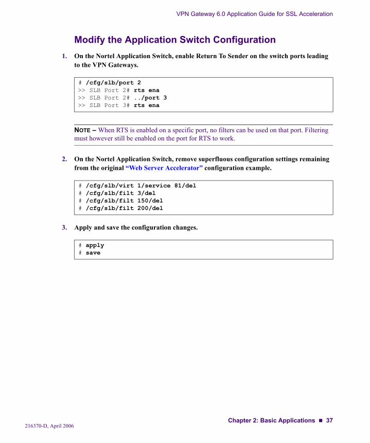
Modify the Application Switch Configuration1. On the Nortel Application Switch, enable Return To Sender on the switch ports leading
to the VPN Gateways.
NOTE – When RTS is enabled on a specific port, no filters can be used on that port. Filtering must however still be enabled on the port for RTS to work.
2. On the Nortel Application Switch, remove superfluous configuration settings remaining from the original “Web Server Accelerator” configuration example.
3. Apply and save the configuration changes.
# /cfg/slb/port 2>> SLB Port 2# rts ena>> SLB Port 2# ../port 3>> SLB Port 3# rts ena
# /cfg/slb/virt 1/service 81/del# /cfg/slb/filt 3/del# /cfg/slb/filt 150/del# /cfg/slb/filt 200/del
# apply# save
216370-D, April 2006Chapter 2: Basic Applications 37
VPN Gateway 6.0 Application Guide for SSL Acceleration
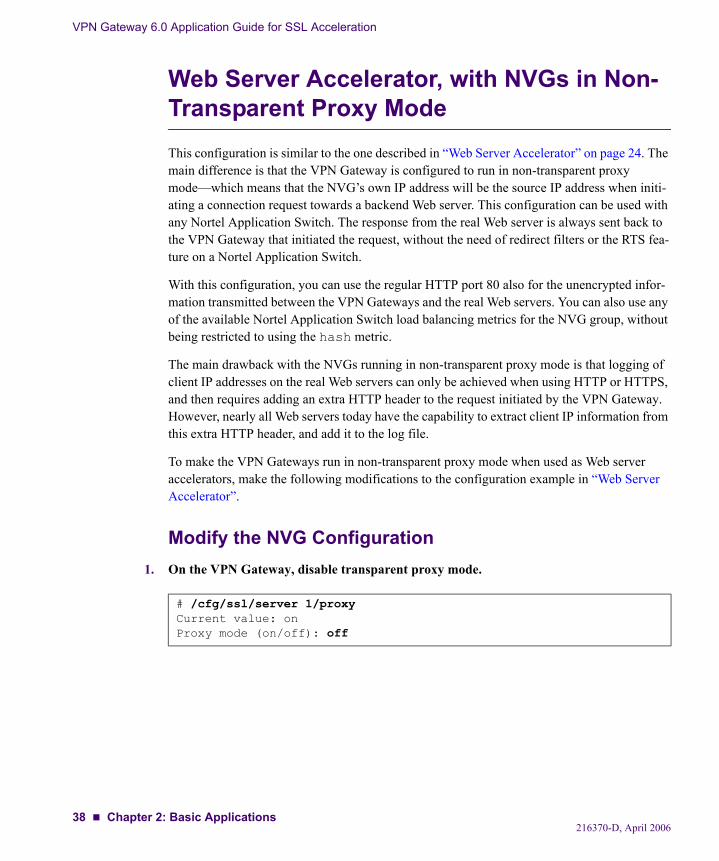
Web Server Accelerator, with NVGs in Non-Transparent Proxy ModeThis configuration is similar to the one described in “Web Server Accelerator” on page 24. The main difference is that the VPN Gateway is configured to run in non-transparent proxy mode—which means that the NVG’s own IP address will be the source IP address when initi-ating a connection request towards a backend Web server. This configuration can be used with any Nortel Application Switch. The response from the real Web server is always sent back to the VPN Gateway that initiated the request, without the need of redirect filters or the RTS fea-ture on a Nortel Application Switch.
With this configuration, you can use the regular HTTP port 80 also for the unencrypted infor-mation transmitted between the VPN Gateways and the real Web servers. You can also use any of the available Nortel Application Switch load balancing metrics for the NVG group, without being restricted to using the hash metric.
The main drawback with the NVGs running in non-transparent proxy mode is that logging of client IP addresses on the real Web servers can only be achieved when using HTTP or HTTPS, and then requires adding an extra HTTP header to the request initiated by the VPN Gateway. However, nearly all Web servers today have the capability to extract client IP information from this extra HTTP header, and add it to the log file.
To make the VPN Gateways run in non-transparent proxy mode when used as Web server accelerators, make the following modifications to the configuration example in “Web Server Accelerator”.
Modify the NVG Configuration1. On the VPN Gateway, disable transparent proxy mode.
# /cfg/ssl/server 1/proxyCurrent value: onProxy mode (on/off): off
216370-D, April 200638 Chapter 2: Basic Applications

VPN Gateway 6.0 Application Guide for SSL Acceleration
2. Specify the real server IP address.
Because transparent proxy is set to off, the real server IP address must explicitly be set to the virtual server IP address (as defined on the Nortel Application Switch).
3. Change the TCP port used by the NVG when initiating requests to the real Web servers.
NOTE – With this configuration change, the real Web servers only need to listen to one port; the default TCP port 80 used for HTTP.
4. Change the virtual SSL server type from generic to http.
This step is required in order to enable access to the HTTP Settings menu.
5. Configure the NVG to use the extra X-Forwarded-For HTTP header when initiating requests to the real Web servers.
6. Apply your configuration changes.
>> Server 1# ripCurrent value: 0.0.0.0Enter IP address to connect to: 192.168.10.100 (example virtual server IP
address)
>> Server 1# rportCurrent value: 0 [81]Enter port to connect to (0-65534): 80
>> Server 1# typeCurrent value: genericType (generic/http): http
>> Server 1# http>> HTTP Settings# addxforCurrent value: offAdd X-Forwarded-For header (on/off/anonymous/remove): on
>> HTTP Settings# apply
216370-D, April 2006Chapter 2: Basic Applications 39
VPN Gateway 6.0 Application Guide for SSL Acceleration
Modify the Application Switch Configuration1. On the Nortel Application Switch, remove superfluous configuration settings remaining
from the original “Web Server Accelerator” configuration example.
2. Apply and save the Application Switch configuration changes.
# /cfg/slb/virt 1/service 81/del# /cfg/slb/filt 3/del# /cfg/slb/filt 150/del# /cfg/slb/filt 200/del# /cfg/slb/port 7/rem 224/filt dis# /cfg/slb/port 8/rem 224/filt dis
# apply# save
216370-D, April 200640 Chapter 2: Basic Applications
VPN Gateway 6.0 Application Guide for SSL Acceleration
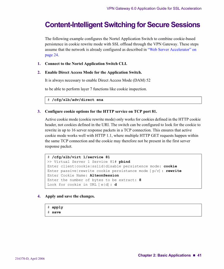
Content-Intelligent Switching for Secure SessionsThe following example configures the Nortel Application Switch to combine cookie-based persistence in cookie rewrite mode with SSL offload through the VPN Gateway. These steps assume that the network is already configured as described in “Web Server Accelerator” on page 24.
1. Connect to the Nortel Application Switch CLI.
2. Enable Direct Access Mode for the Application Switch.
It is always necessary to enable Direct Access Mode (DAM) 52
to be able to perform layer 7 functions like cookie inspection.
3. Configure cookie options for the HTTP service on TCP port 81.
Active cookie mode (cookie rewrite mode) only works for cookies defined in the HTTP cookie header, not cookies defined in the URI. The switch can be configured to look for the cookie to rewrite in up to 16 server response packets in a TCP connection. This ensures that active cookie mode works well with HTTP 1.1, where multiple HTTP GET requests happen within the same TCP connection and the cookie may therefore not be present in the first server response packet.
4. Apply and save the changes.
# /cfg/slb/adv/direct ena
# /cfg/slb/virt 1/service 81>> Virtual Server 1 Service 81# pbindEnter client|cookie|sslid|disable persistence mode: cookieEnter passive|rewrite cookie persistance mode [p/r]: rewriteEnter Cookie Name: AlteonSessionEnter the number of bytes to be extract: 8Look for cookie in URL [e|d]: d
# apply# save
216370-D, April 2006Chapter 2: Basic Applications 41
VPN Gateway 6.0 Application Guide for SSL Acceleration
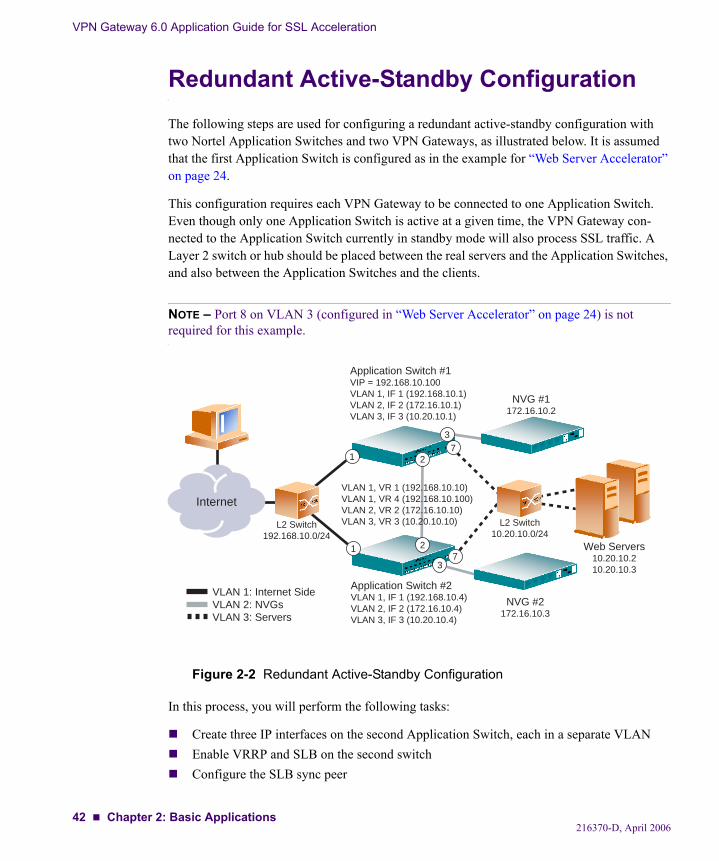
Redundant Active-Standby ConfigurationThe following steps are used for configuring a redundant active-standby configuration with two Nortel Application Switches and two VPN Gateways, as illustrated below. It is assumed that the first Application Switch is configured as in the example for “Web Server Accelerator” on page 24.
This configuration requires each VPN Gateway to be connected to one Application Switch. Even though only one Application Switch is active at a given time, the VPN Gateway con-nected to the Application Switch currently in standby mode will also process SSL traffic. A Layer 2 switch or hub should be placed between the real servers and the Application Switches, and also between the Application Switches and the clients.
NOTE – Port 8 on VLAN 3 (configured in “Web Server Accelerator” on page 24) is not required for this example.
Figure 2-2 Redundant Active-Standby Configuration
In this process, you will perform the following tasks:
Create three IP interfaces on the second Application Switch, each in a separate VLANEnable VRRP and SLB on the second switchConfigure the SLB sync peer
Internet
1
1
2
2
7
7
NVG #1172.16.10.2
Web Servers10.20.10.210.20.10.3
L2 Switch10.20.10.0/24
L2 Switch192.168.10.0/24
VLAN 1: Internet SideVLAN 2: NVGs VLAN 3: Servers
Application Switch #1VIP = 192.168.10.100VLAN 1, IF 1 (192.168.10.1)VLAN 2, IF 2 (172.16.10.1)VLAN 3, IF 3 (10.20.10.1)
Application Switch #2VLAN 1, IF 1 (192.168.10.4)VLAN 2, IF 2 (172.16.10.4)VLAN 3, IF 3 (10.20.10.4)
VLAN 1, VR 1 (192.168.10.10)VLAN 1, VR 4 (192.168.10.100)VLAN 2, VR 2 (172.16.10.10)VLAN 3, VR 3 (10.20.10.10)
NVG #2172.16.10.3
3
3
216370-D, April 200642 Chapter 2: Basic Applications
VPN Gateway 6.0 Application Guide for SSL Acceleration
Configure Application Switch 2
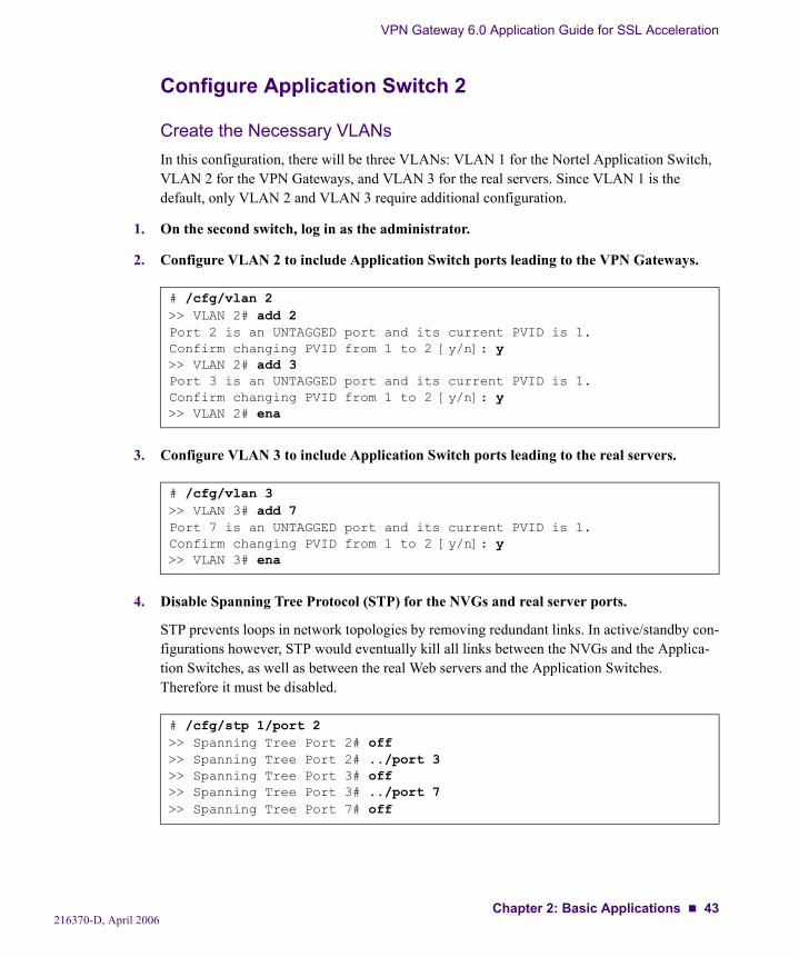
Create the Necessary VLANsIn this configuration, there will be three VLANs: VLAN 1 for the Nortel Application Switch, VLAN 2 for the VPN Gateways, and VLAN 3 for the real servers. Since VLAN 1 is the default, only VLAN 2 and VLAN 3 require additional configuration.
1. On the second switch, log in as the administrator.
2. Configure VLAN 2 to include Application Switch ports leading to the VPN Gateways.
3. Configure VLAN 3 to include Application Switch ports leading to the real servers.
4. Disable Spanning Tree Protocol (STP) for the NVGs and real server ports.
STP prevents loops in network topologies by removing redundant links. In active/standby con-figurations however, STP would eventually kill all links between the NVGs and the Applica-tion Switches, as well as between the real Web servers and the Application Switches. Therefore it must be disabled.
# /cfg/vlan 2>> VLAN 2# add 2Port 2 is an UNTAGGED port and its current PVID is 1.Confirm changing PVID from 1 to 2 [y/n]: y>> VLAN 2# add 3Port 3 is an UNTAGGED port and its current PVID is 1.Confirm changing PVID from 1 to 2 [y/n]: y>> VLAN 2# ena
# /cfg/vlan 3>> VLAN 3# add 7Port 7 is an UNTAGGED port and its current PVID is 1.Confirm changing PVID from 1 to 2 [y/n]: y>> VLAN 3# ena
# /cfg/stp 1/port 2>> Spanning Tree Port 2# off>> Spanning Tree Port 2# ../port 3>> Spanning Tree Port 3# off>> Spanning Tree Port 3# ../port 7>> Spanning Tree Port 7# off
216370-D, April 2006Chapter 2: Basic Applications 43

VPN Gateway 6.0 Application Guide for SSL Acceleration
Configure IP Interfaces for Each VLAN
1. Configure an IP interface for client traffic on the Application Switch.
2. Configure an IP interface for NVG traffic.
3. Configure an IP interface for the real server traffic.
4. Apply the changes.
# /cfg/ip/if 1>> IP Interface 1# addr 192.168.10.4>> IP Interface 1# mask 255.255.255.0>> IP Interface 1# ena
# /cfg/ip/if 2>> IP Interface 2# addr 172.16.10.4>> IP Interface 2# mask 255.255.255.0>> IP Interface 2# vlan 2>> IP Interface 2# ena
# /cfg/ip/if 3>> IP Interface 3# addr 10.20.10.4>> IP Interface 3# mask 255.255.255.0>> IP Interface 3# vlan 3>> IP Interface 3# ena
# apply
216370-D, April 200644 Chapter 2: Basic Applications
VPN Gateway 6.0 Application Guide for SSL Acceleration
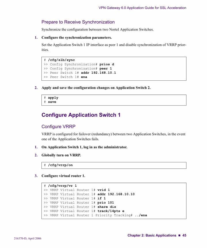
Prepare to Receive SynchronizationSynchronize the configuration between two Nortel Application Switches.
1. Configure the synchronization parameters.
Set the Application Switch 1 IP interface as peer 1 and disable synchronization of VRRP prior-ities.
2. Apply and save the configuration changes on Application Switch 2.
Configure Application Switch 1
Configure VRRPVRRP is configured for failover (redundancy) between two Application Switches, in the event one of the Application Switches fails.
1. On Application Switch 1, log in as the administrator.
2. Globally turn on VRRP.
3. Configure virtual router 1.
# /cfg/slb/sync>> Config Synchronization# prios d>> Config Synchronization# peer 1>> Peer Switch 1# addr 192.168.10.1>> Peer Switch 1# ena
# apply# save
# /cfg/vrrp/on
# /cfg/vrrp/vr 1>> VRRP Virtual Router 1# vrid 1>> VRRP Virtual Router 1# addr 192.168.10.10>> VRRP Virtual Router 1# if 1>> VRRP Virtual Router 1# prio 101>> VRRP Virtual Router 1# share dis>> VRRP Virtual Router 1# track/14pts e>> VRRP Virtual Router 1 Priority Tracking# ../ena
216370-D, April 2006Chapter 2: Basic Applications 45
VPN Gateway 6.0 Application Guide for SSL Acceleration
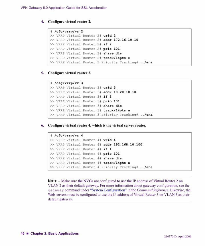
4. Configure virtual router 2.
5. Configure virtual router 3.
6. Configure virtual router 4, which is the virtual server router.
NOTE – Make sure the NVGs are configured to use the IP address of Virtual Router 2 on VLAN 2 as their default gateway. For more information about gateway configuration, see the gateway command under “System Configuration” in the Command Reference. Likewise, the Web servers must be configured to use the IP address of Virtual Router 3 on VLAN 3 as their default gateway.
# /cfg/vrrp/vr 2>> VRRP Virtual Router 2# vrid 2>> VRRP Virtual Router 2# addr 172.16.10.10>> VRRP Virtual Router 2# if 2>> VRRP Virtual Router 2# prio 101>> VRRP Virtual Router 2# share dis>> VRRP Virtual Router 2# track/14pts e>> VRRP Virtual Router 2 Priority Tracking# ../ena
# /cfg/vrrp/vr 3>> VRRP Virtual Router 3# vrid 3>> VRRP Virtual Router 3# addr 10.20.10.10>> VRRP Virtual Router 3# if 3>> VRRP Virtual Router 3# prio 101>> VRRP Virtual Router 3# share dis>> VRRP Virtual Router 3# track/14pts e>> VRRP Virtual Router 3 Priority Tracking# ../ena
# /cfg/vrrp/vr 4>> VRRP Virtual Router 4# vrid 4>> VRRP Virtual Router 4# addr 192.168.10.100>> VRRP Virtual Router 4# if 1>> VRRP Virtual Router 4# prio 101>> VRRP Virtual Router 4# share dis>> VRRP Virtual Router 4# track/14pts e>> VRRP Virtual Router 4 Priority Tracking# ../ena
216370-D, April 200646 Chapter 2: Basic Applications
VPN Gateway 6.0 Application Guide for SSL Acceleration
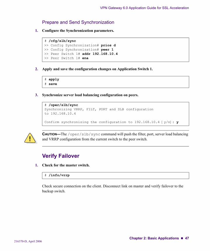
Prepare and Send Synchronization
1. Configure the Synchronization parameters.
2. Apply and save the configuration changes on Application Switch 1.
3. Synchronize server load balancing configuration on peers.
Verify Failover1. Check for the master switch.
Check secure connection on the client. Disconnect link on master and verify failover to the backup switch.
# /cfg/slb/sync>> Config Synchronization# prios d>> Config Synchronization# peer 1>> Peer Switch 1# addr 192.168.10.4>> Peer Switch 1# ena
# apply# save
# /oper/slb/syncSynchronizing VRRP, FILT, PORT and SLB configurationto 192.168.10.4
Confirm synchronizing the configuration to 192.168.10.4 [y/n]: y
!CAUTION—The /oper/slb/sync command will push the filter, port, server load balancing and VRRP configuration from the current switch to the peer switch.
# /info/vrrp
216370-D, April 2006Chapter 2: Basic Applications 47
VPN Gateway 6.0 Application Guide for SSL Acceleration
Redundant Active-Standby Configuration with NVG Port FailoverThe following steps are used for configuring a port failover solution, in which each VPN Gate-way is connected to two Nortel Application Switches by using two physical network ports on each NVG. Should one network port fail on a VPN Gateway, the active link is immediately switched over to the other port and the NVG continues to process SSL requests uninterrupted.
The port failover configuration example assumes that you already have a redundant active-standby configuration with two Nortel Application Switches and two VPN Gateways, as described in “Redundant Active-Standby Configuration” on page 42. Note that the Redundant Active-Standby configuration example in turn assumes that the first Application Switch is con-figured as in the example for “Web Server Accelerator” on page 24.
If your NVG cluster consists of more than two devices, you may want to place Layer 2 switches between the NVGs and the Application Switches in order to decrease the number of ports used on the Application Switches. In that case, port 1 on each VPN Gateway should be connected to one Layer 2 switch, and port 2 on each VPN Gateway connected to another Layer 2 switch. Both Layer 2 switches must in turn be connected to both Application Switches. With Layer 2 switches placed between the NVGs and the Application Switches, no primary port should be configured in the NVG cluster.
216370-D, April 200648 Chapter 2: Basic Applications
VPN Gateway 6.0 Application Guide for SSL Acceleration
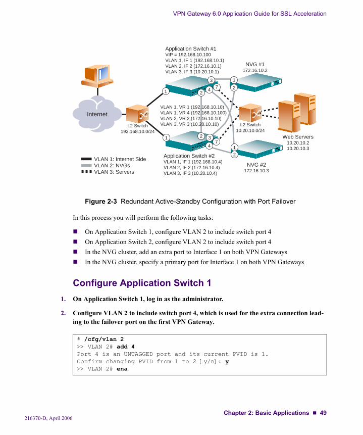
Figure 2-3 Redundant Active-Standby Configuration with Port Failover
In this process you will perform the following tasks:
On Application Switch 1, configure VLAN 2 to include switch port 4On Application Switch 2, configure VLAN 2 to include switch port 4In the NVG cluster, add an extra port to Interface 1 on both VPN GatewaysIn the NVG cluster, specify a primary port for Interface 1 on both VPN Gateways
Configure Application Switch 11. On Application Switch 1, log in as the administrator.
2. Configure VLAN 2 to include switch port 4, which is used for the extra connection lead-ing to the failover port on the first VPN Gateway.
# /cfg/vlan 2>> VLAN 2# add 4Port 4 is an UNTAGGED port and its current PVID is 1.Confirm changing PVID from 1 to 2 [y/n]: y>> VLAN 2# ena
Internet
1
1
2
2
7
7
NVG #1172.16.10.2
Web Servers10.20.10.210.20.10.3
L2 Switch10.20.10.0/24
L2 Switch192.168.10.0/24
VLAN 1: Internet SideVLAN 2: NVGsVLAN 3: Servers
Application Switch #1VIP = 192.168.10.100VLAN 1, IF 1 (192.168.10.1)VLAN 2, IF 2 (172.16.10.1)VLAN 3, IF 3 (10.20.10.1)
Application Switch #2VLAN 1, IF 1 (192.168.10.4)VLAN 2, IF 2 (172.16.10.4)VLAN 3, IF 3 (10.20.10.4)
VLAN 1, VR 1 (192.168.10.10)VLAN 1, VR 4 (192.168.10.100)VLAN 2, VR 2 (172.16.10.10)VLAN 3, VR 3 (10.20.10.10)
NVG #2172.16.10.3
3
3
1
2
4
4 1
2
216370-D, April 2006Chapter 2: Basic Applications 49

VPN Gateway 6.0 Application Guide for SSL Acceleration
3. Apply and save the configuration changes on Application Switch 1.
Configure Application Switch 21. On Application Switch 2, log in as the administrator.
2. Configure VLAN 2 to include switch port 4, which is used for the extra connection lead-ing to the failover port on the second VPN Gateway.
3. Apply and save the configuration changes on Application Switch 2.
Configure the NVGsAll configuration changes will automatically be propagated to all VPN Gateways in the cluster.
1. Log in as the administrator to the NVG cluster by using a Telnet or SSH connection to the Management IP address (MIP). You can also use a direct serial connection to one of the NVGs.
# apply# save
# /cfg/vlan 2>> VLAN 2# add 4Port 4 is an UNTAGGED port and its current PVID is 1.Confirm changing PVID from 1 to 2 [y/n]: y>> VLAN 2# ena
# apply# save
login: adminPassword:
216370-D, April 200650 Chapter 2: Basic Applications
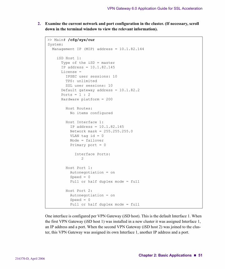
VPN Gateway 6.0 Application Guide for SSL Acceleration
2. Examine the current network and port configuration in the cluster. (If necessary, scroll down in the terminal window to view the relevant information).
One interface is configured per VPN Gateway (iSD host). This is the default Interface 1. When the first VPN Gateway (iSD host 1) was installed in a new cluster it was assigned Interface 1, an IP address and a port. When the second VPN Gateway (iSD host 2) was joined to the clus-ter, this VPN Gateway was assigned its own Interface 1, another IP address and a port.
>> Main# /cfg/sys/curSystem: Management IP (MIP) address = 10.1.82.144
iSD Host 1: Type of the iSD = master IP address = 10.1.82.145 License = IPSEC user sessions: 10 TPS: unlimited SSL user sessions: 10 Default gateway address = 10.1.82.2 Ports = 1 : 2 Hardware platform = 200
Host Routes: No items configured
Host Interface 1: IP address = 10.1.82.145 Network mask = 255.255.255.0 VLAN tag id = 0 Mode = failover Primary port = 0
Interface Ports: 2
Host Port 1: Autonegotiation = on Speed = 0 Full or half duplex mode = full
Host Port 2: Autonegotiation = on Speed = 0 Full or half duplex mode = full
216370-D, April 2006Chapter 2: Basic Applications 51
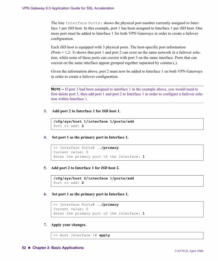
VPN Gateway 6.0 Application Guide for SSL Acceleration
The line Interface Ports: shows the physical port number currently assigned to Inter-face 1 per iSD host. In this example, port 1 has been assigned to Interface 1 per iSD host. One more port must be added to Interface 1 for both VPN Gateways in order to create a failover configuration.
Each iSD host is equipped with 3 physical ports. The host-specific port information (Ports = 1,2: 3) shows that port 1 and port 2 can exist on the same network in a failover solu-tion, while none of these ports can coexist with port 3 on the same interface. Ports that can coexist on the same interface appear grouped together separated by comma (,).
Given the information above, port 2 must now be added to Interface 1 on both VPN Gateways in order to create a failover configuration.
NOTE – If port 3 had been assigned to interface 1 in the example above, you would need to first delete port 3, then add port 1 and port 2 to Interface 1 in order to configure a failover solu-tion within Interface 1.
3. Add port 2 to Interface 1 for iSD host 1.
4. Set port 1 as the primary port in Interface 1.
5. Add port 2 to Interface 1 for iSD host 2.
6. Set port 1 as the primary port in Interface 1.
7. Apply your changes.
/cfg/sys/host 1/interface 1/ports/addPort to add: 2
>> Interface Ports# ../primaryCurrent value: 0Enter the primary port of the Interface: 1
/cfg/sys/host 2/interface 1/ports/addPort to add: 2
>> Interface Ports# ../primaryCurrent value: 0Enter the primary port of the Interface: 1
>> Host Interface 1# apply
216370-D, April 200652 Chapter 2: Basic Applications
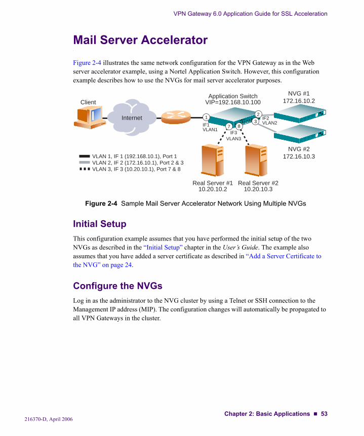
VPN Gateway 6.0 Application Guide for SSL Acceleration
Mail Server AcceleratorFigure 2-4 illustrates the same network configuration for the VPN Gateway as in the Web server accelerator example, using a Nortel Application Switch. However, this configuration example describes how to use the NVGs for mail server accelerator purposes.
Figure 2-4 Sample Mail Server Accelerator Network Using Multiple NVGs
Initial SetupThis configuration example assumes that you have performed the initial setup of the two NVGs as described in the “Initial Setup” chapter in the User’s Guide. The example also assumes that you have added a server certificate as described in “Add a Server Certificate to the NVG” on page 24.
Configure the NVGsLog in as the administrator to the NVG cluster by using a Telnet or SSH connection to the Management IP address (MIP). The configuration changes will automatically be propagated to all VPN Gateways in the cluster.
Internet
ClientApplication Switch
VIP=192.168.10.100
Real Server #110.20.10.2
Real Server #210.20.10.3
13
2
87
NVG #1172.16.10.2
NVG #2172.16.10.3
IF3VLAN3
IF2VLAN2IF1
VLAN1
VLAN 1, IF 1 (192.168.10.1), Port 1VLAN 2, IF 2 (172.16.10.1), Port 2 & 3VLAN 3, IF 3 (10.20.10.1), Port 7 & 8
216370-D, April 2006Chapter 2: Basic Applications 53
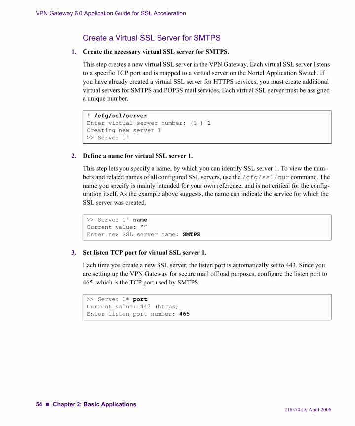
VPN Gateway 6.0 Application Guide for SSL Acceleration
Create a Virtual SSL Server for SMTPS
1. Create the necessary virtual SSL server for SMTPS.
This step creates a new virtual SSL server in the VPN Gateway. Each virtual SSL server listens to a specific TCP port and is mapped to a virtual server on the Nortel Application Switch. If you have already created a virtual SSL server for HTTPS services, you must create additional virtual servers for SMTPS and POP3S mail services. Each virtual SSL server must be assigned a unique number.
2. Define a name for virtual SSL server 1.
This step lets you specify a name, by which you can identify SSL server 1. To view the num-bers and related names of all configured SSL servers, use the /cfg/ssl/cur command. The name you specify is mainly intended for your own reference, and is not critical for the config-uration itself. As the example above suggests, the name can indicate the service for which the SSL server was created.
3. Set listen TCP port for virtual SSL server 1.
Each time you create a new SSL server, the listen port is automatically set to 443. Since you are setting up the VPN Gateway for secure mail offload purposes, configure the listen port to 465, which is the TCP port used by SMTPS.
# /cfg/ssl/serverEnter virtual server number: (1-) 1Creating new server 1>> Server 1#
>> Server 1# nameCurrent value: “”Enter new SSL server name: SMTPS
>> Server 1# portCurrent value: 443 (https)Enter listen port number: 465
216370-D, April 200654 Chapter 2: Basic Applications
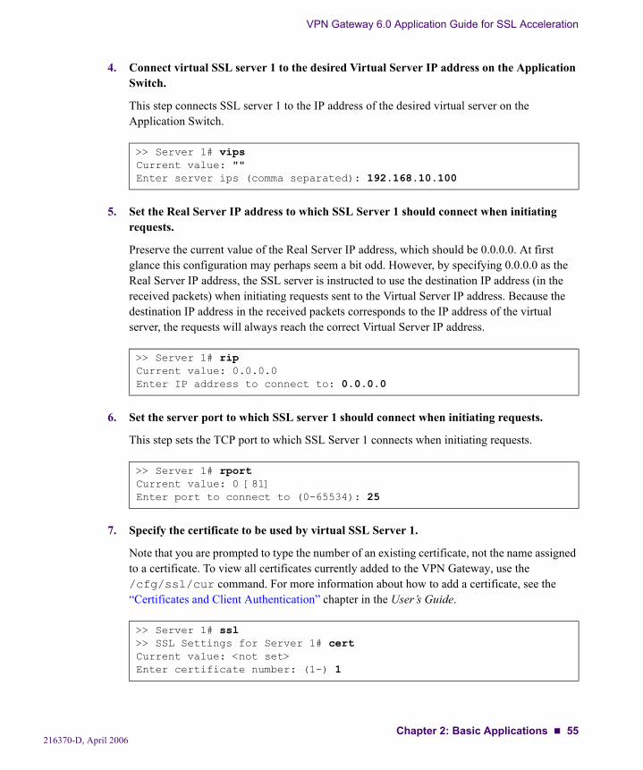
VPN Gateway 6.0 Application Guide for SSL Acceleration
4. Connect virtual SSL server 1 to the desired Virtual Server IP address on the Application Switch.
This step connects SSL server 1 to the IP address of the desired virtual server on the Application Switch.
5. Set the Real Server IP address to which SSL Server 1 should connect when initiating requests.
Preserve the current value of the Real Server IP address, which should be 0.0.0.0. At first glance this configuration may perhaps seem a bit odd. However, by specifying 0.0.0.0 as the Real Server IP address, the SSL server is instructed to use the destination IP address (in the received packets) when initiating requests sent to the Virtual Server IP address. Because the destination IP address in the received packets corresponds to the IP address of the virtual server, the requests will always reach the correct Virtual Server IP address.
6. Set the server port to which SSL server 1 should connect when initiating requests.
This step sets the TCP port to which SSL Server 1 connects when initiating requests.
7. Specify the certificate to be used by virtual SSL Server 1.
Note that you are prompted to type the number of an existing certificate, not the name assigned to a certificate. To view all certificates currently added to the VPN Gateway, use the /cfg/ssl/cur command. For more information about how to add a certificate, see the “Certificates and Client Authentication” chapter in the User’s Guide.
>> Server 1# vipsCurrent value: ""Enter server ips (comma separated): 192.168.10.100
>> Server 1# ripCurrent value: 0.0.0.0Enter IP address to connect to: 0.0.0.0
>> Server 1# rportCurrent value: 0 [81]Enter port to connect to (0-65534): 25
>> Server 1# ssl>> SSL Settings for Server 1# certCurrent value: <not set>Enter certificate number: (1-) 1
216370-D, April 2006Chapter 2: Basic Applications 55
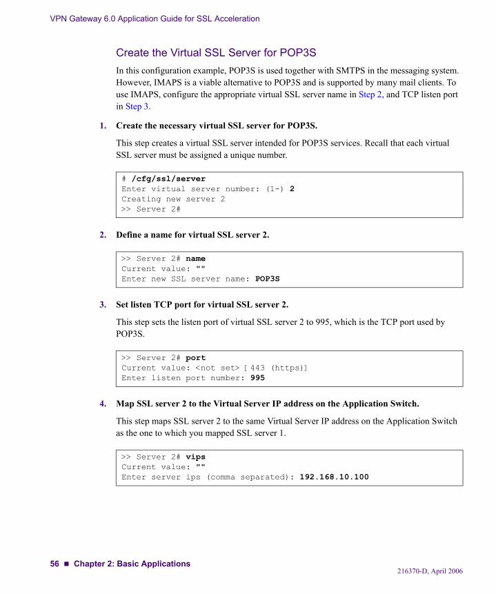
VPN Gateway 6.0 Application Guide for SSL Acceleration
Create the Virtual SSL Server for POP3SIn this configuration example, POP3S is used together with SMTPS in the messaging system. However, IMAPS is a viable alternative to POP3S and is supported by many mail clients. To use IMAPS, configure the appropriate virtual SSL server name in Step 2, and TCP listen port in Step 3.
1. Create the necessary virtual SSL server for POP3S.
This step creates a virtual SSL server intended for POP3S services. Recall that each virtual SSL server must be assigned a unique number.
2. Define a name for virtual SSL server 2.
3. Set listen TCP port for virtual SSL server 2.
This step sets the listen port of virtual SSL server 2 to 995, which is the TCP port used by POP3S.
4. Map SSL server 2 to the Virtual Server IP address on the Application Switch.
This step maps SSL server 2 to the same Virtual Server IP address on the Application Switch as the one to which you mapped SSL server 1.
# /cfg/ssl/serverEnter virtual server number: (1-) 2Creating new server 2>> Server 2#
>> Server 2# nameCurrent value: ""Enter new SSL server name: POP3S
>> Server 2# portCurrent value: <not set> [443 (https)]Enter listen port number: 995
>> Server 2# vipsCurrent value: ""Enter server ips (comma separated): 192.168.10.100
216370-D, April 200656 Chapter 2: Basic Applications
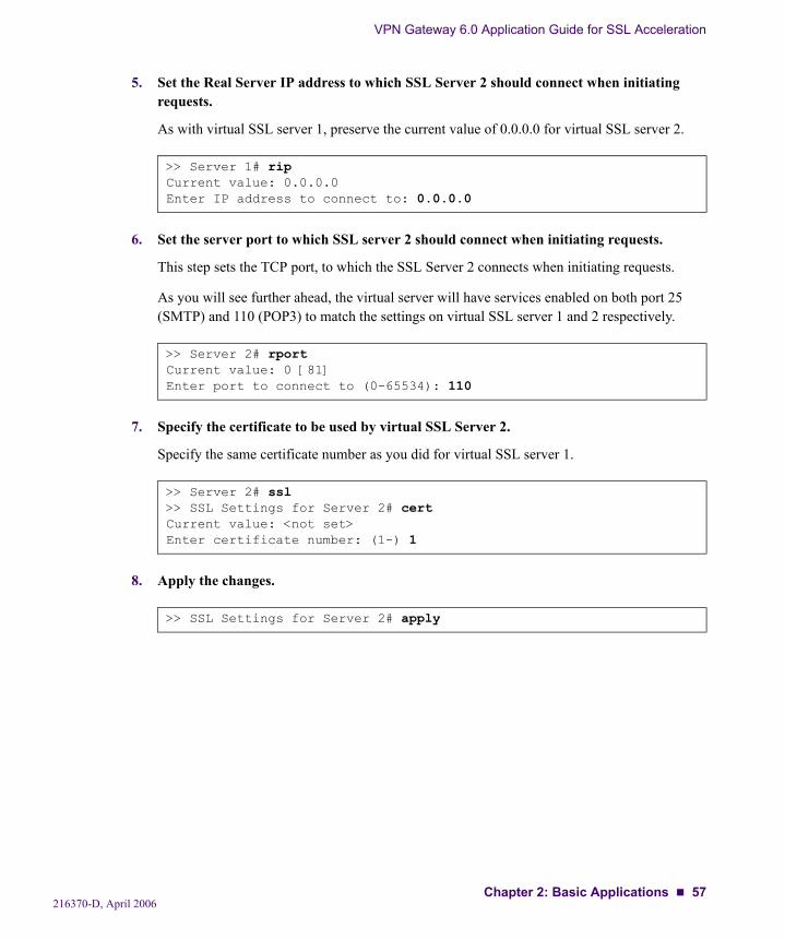
VPN Gateway 6.0 Application Guide for SSL Acceleration
5. Set the Real Server IP address to which SSL Server 2 should connect when initiating requests.
As with virtual SSL server 1, preserve the current value of 0.0.0.0 for virtual SSL server 2.
6. Set the server port to which SSL server 2 should connect when initiating requests.
This step sets the TCP port, to which the SSL Server 2 connects when initiating requests.
As you will see further ahead, the virtual server will have services enabled on both port 25 (SMTP) and 110 (POP3) to match the settings on virtual SSL server 1 and 2 respectively.
7. Specify the certificate to be used by virtual SSL Server 2.
Specify the same certificate number as you did for virtual SSL server 1.
8. Apply the changes.
>> Server 1# ripCurrent value: 0.0.0.0Enter IP address to connect to: 0.0.0.0
>> Server 2# rportCurrent value: 0 [81]Enter port to connect to (0-65534): 110
>> Server 2# ssl>> SSL Settings for Server 2# certCurrent value: <not set>Enter certificate number: (1-) 1
>> SSL Settings for Server 2# apply
216370-D, April 2006Chapter 2: Basic Applications 57
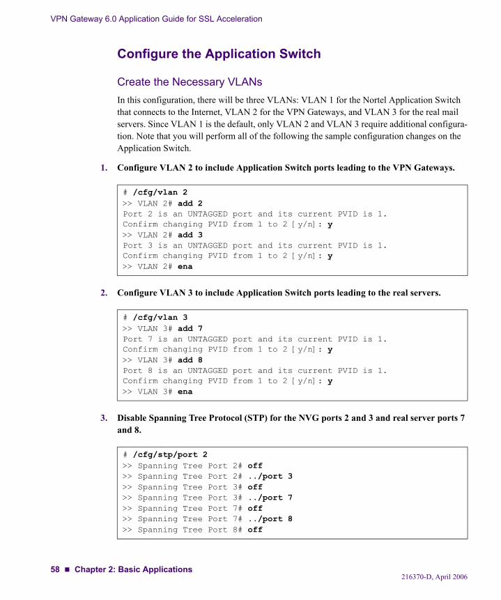
VPN Gateway 6.0 Application Guide for SSL Acceleration
Configure the Application Switch
Create the Necessary VLANsIn this configuration, there will be three VLANs: VLAN 1 for the Nortel Application Switch that connects to the Internet, VLAN 2 for the VPN Gateways, and VLAN 3 for the real mail servers. Since VLAN 1 is the default, only VLAN 2 and VLAN 3 require additional configura-tion. Note that you will perform all of the following the sample configuration changes on the Application Switch.
1. Configure VLAN 2 to include Application Switch ports leading to the VPN Gateways.
2. Configure VLAN 3 to include Application Switch ports leading to the real servers.
3. Disable Spanning Tree Protocol (STP) for the NVG ports 2 and 3 and real server ports 7 and 8.
# /cfg/vlan 2>> VLAN 2# add 2Port 2 is an UNTAGGED port and its current PVID is 1.Confirm changing PVID from 1 to 2 [y/n]: y>> VLAN 2# add 3Port 3 is an UNTAGGED port and its current PVID is 1.Confirm changing PVID from 1 to 2 [y/n]: y>> VLAN 2# ena
# /cfg/vlan 3>> VLAN 3# add 7Port 7 is an UNTAGGED port and its current PVID is 1.Confirm changing PVID from 1 to 2 [y/n]: y>> VLAN 3# add 8Port 8 is an UNTAGGED port and its current PVID is 1.Confirm changing PVID from 1 to 2 [y/n]: y>> VLAN 3# ena
# /cfg/stp/port 2>> Spanning Tree Port 2# off>> Spanning Tree Port 2# ../port 3>> Spanning Tree Port 3# off>> Spanning Tree Port 3# ../port 7>> Spanning Tree Port 7# off>> Spanning Tree Port 7# ../port 8>> Spanning Tree Port 8# off
216370-D, April 200658 Chapter 2: Basic Applications
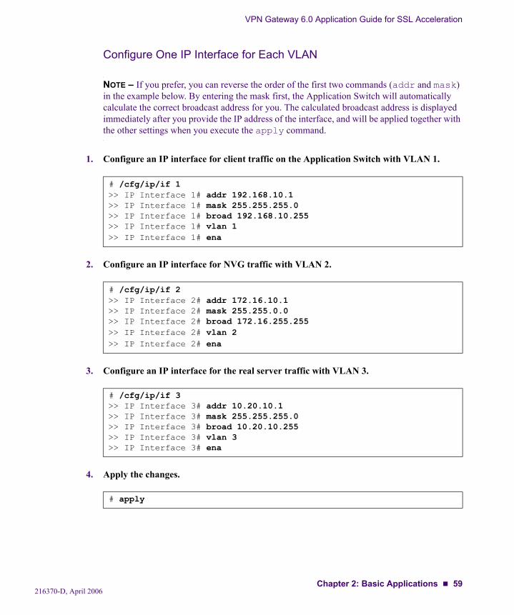
VPN Gateway 6.0 Application Guide for SSL Acceleration
Configure One IP Interface for Each VLAN
NOTE – If you prefer, you can reverse the order of the first two commands (addr and mask) in the example below. By entering the mask first, the Application Switch will automatically calculate the correct broadcast address for you. The calculated broadcast address is displayed immediately after you provide the IP address of the interface, and will be applied together with the other settings when you execute the apply command.
1. Configure an IP interface for client traffic on the Application Switch with VLAN 1.
2. Configure an IP interface for NVG traffic with VLAN 2.
3. Configure an IP interface for the real server traffic with VLAN 3.
4. Apply the changes.
# /cfg/ip/if 1>> IP Interface 1# addr 192.168.10.1>> IP Interface 1# mask 255.255.255.0>> IP Interface 1# broad 192.168.10.255>> IP Interface 1# vlan 1>> IP Interface 1# ena
# /cfg/ip/if 2>> IP Interface 2# addr 172.16.10.1>> IP Interface 2# mask 255.255.0.0>> IP Interface 2# broad 172.16.255.255>> IP Interface 2# vlan 2>> IP Interface 2# ena
# /cfg/ip/if 3>> IP Interface 3# addr 10.20.10.1>> IP Interface 3# mask 255.255.255.0>> IP Interface 3# broad 10.20.10.255>> IP Interface 3# vlan 3>> IP Interface 3# ena
# apply
216370-D, April 2006Chapter 2: Basic Applications 59
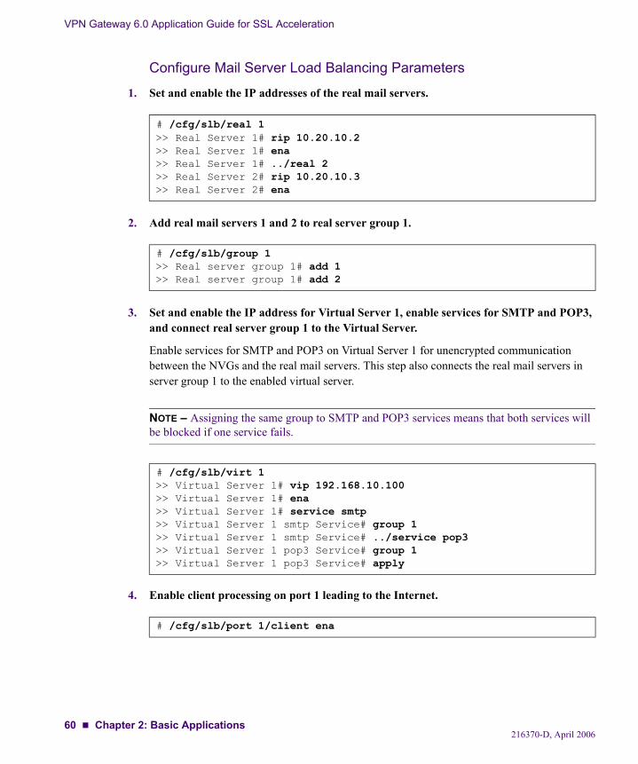
VPN Gateway 6.0 Application Guide for SSL Acceleration
Configure Mail Server Load Balancing Parameters
1. Set and enable the IP addresses of the real mail servers.
2. Add real mail servers 1 and 2 to real server group 1.
3. Set and enable the IP address for Virtual Server 1, enable services for SMTP and POP3, and connect real server group 1 to the Virtual Server.
Enable services for SMTP and POP3 on Virtual Server 1 for unencrypted communication between the NVGs and the real mail servers. This step also connects the real mail servers in server group 1 to the enabled virtual server.
NOTE – Assigning the same group to SMTP and POP3 services means that both services will be blocked if one service fails.
4. Enable client processing on port 1 leading to the Internet.
# /cfg/slb/real 1>> Real Server 1# rip 10.20.10.2>> Real Server 1# ena>> Real Server 1# ../real 2>> Real Server 2# rip 10.20.10.3>> Real Server 2# ena
# /cfg/slb/group 1>> Real server group 1# add 1>> Real server group 1# add 2
# /cfg/slb/virt 1>> Virtual Server 1# vip 192.168.10.100>> Virtual Server 1# ena>> Virtual Server 1# service smtp>> Virtual Server 1 smtp Service# group 1>> Virtual Server 1 smtp Service# ../service pop3>> Virtual Server 1 pop3 Service# group 1>> Virtual Server 1 pop3 Service# apply
# /cfg/slb/port 1/client ena
216370-D, April 200660 Chapter 2: Basic Applications
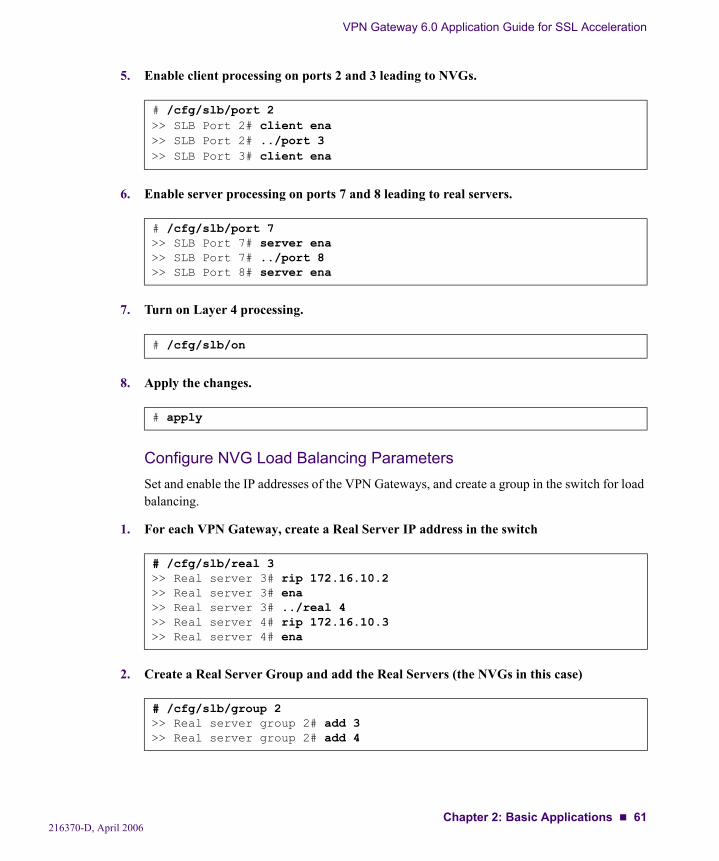
VPN Gateway 6.0 Application Guide for SSL Acceleration
5. Enable client processing on ports 2 and 3 leading to NVGs.
6. Enable server processing on ports 7 and 8 leading to real servers.
7. Turn on Layer 4 processing.
8. Apply the changes.
Configure NVG Load Balancing ParametersSet and enable the IP addresses of the VPN Gateways, and create a group in the switch for load balancing.
1. For each VPN Gateway, create a Real Server IP address in the switch
2. Create a Real Server Group and add the Real Servers (the NVGs in this case)
# /cfg/slb/port 2>> SLB Port 2# client ena>> SLB Port 2# ../port 3>> SLB Port 3# client ena
# /cfg/slb/port 7>> SLB Port 7# server ena>> SLB Port 7# ../port 8>> SLB Port 8# server ena
# /cfg/slb/on
# apply
# /cfg/slb/real 3>> Real server 3# rip 172.16.10.2>> Real server 3# ena>> Real server 3# ../real 4>> Real server 4# rip 172.16.10.3>> Real server 4# ena
# /cfg/slb/group 2>> Real server group 2# add 3>> Real server group 2# add 4
216370-D, April 2006Chapter 2: Basic Applications 61
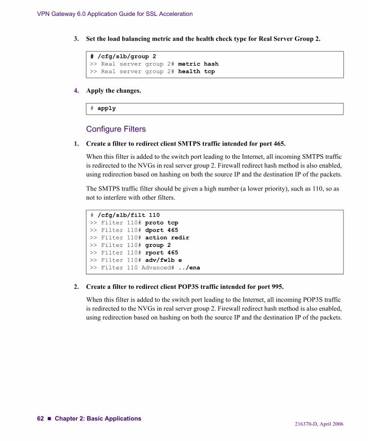
VPN Gateway 6.0 Application Guide for SSL Acceleration
3. Set the load balancing metric and the health check type for Real Server Group 2.
4. Apply the changes.
Configure Filters
1. Create a filter to redirect client SMTPS traffic intended for port 465.
When this filter is added to the switch port leading to the Internet, all incoming SMTPS traffic is redirected to the NVGs in real server group 2. Firewall redirect hash method is also enabled, using redirection based on hashing on both the source IP and the destination IP of the packets.
The SMTPS traffic filter should be given a high number (a lower priority), such as 110, so as not to interfere with other filters.
2. Create a filter to redirect client POP3S traffic intended for port 995.
When this filter is added to the switch port leading to the Internet, all incoming POP3S traffic is redirected to the NVGs in real server group 2. Firewall redirect hash method is also enabled, using redirection based on hashing on both the source IP and the destination IP of the packets.
# /cfg/slb/group 2>> Real server group 2# metric hash>> Real server group 2# health tcp
# apply
# /cfg/slb/filt 110>> Filter 110# proto tcp>> Filter 110# dport 465>> Filter 110# action redir>> Filter 110# group 2>> Filter 110# rport 465>> Filter 110# adv/fwlb e>> Filter 110 Advanced# ../ena
216370-D, April 200662 Chapter 2: Basic Applications
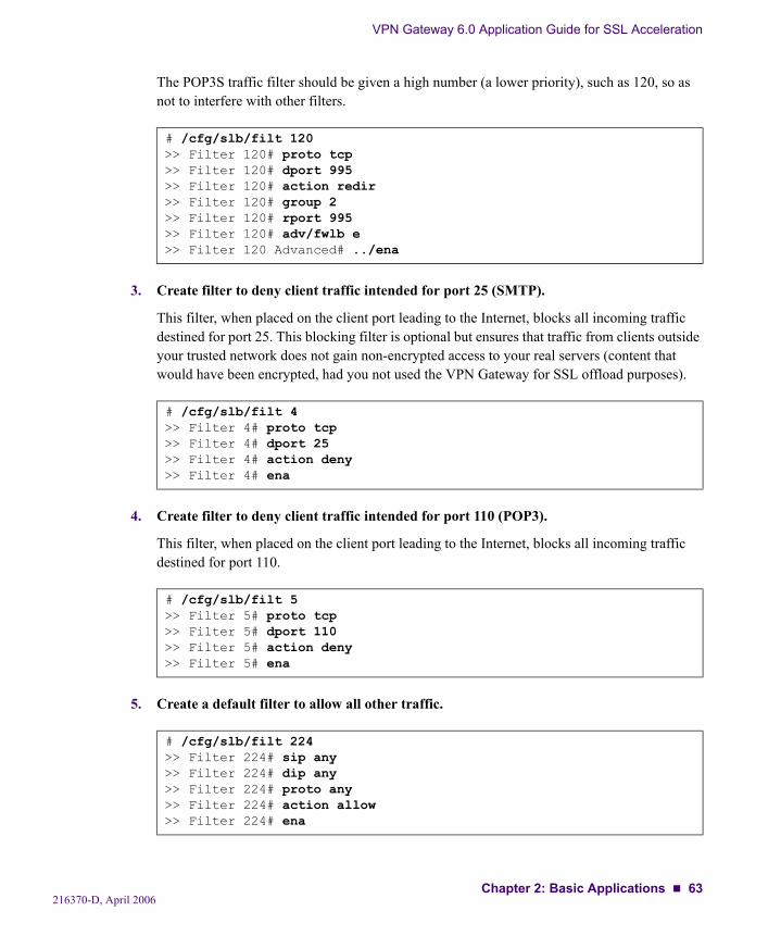
VPN Gateway 6.0 Application Guide for SSL Acceleration
The POP3S traffic filter should be given a high number (a lower priority), such as 120, so as not to interfere with other filters.
3. Create filter to deny client traffic intended for port 25 (SMTP).
This filter, when placed on the client port leading to the Internet, blocks all incoming traffic destined for port 25. This blocking filter is optional but ensures that traffic from clients outside your trusted network does not gain non-encrypted access to your real servers (content that would have been encrypted, had you not used the VPN Gateway for SSL offload purposes).
4. Create filter to deny client traffic intended for port 110 (POP3).
This filter, when placed on the client port leading to the Internet, blocks all incoming traffic destined for port 110.
5. Create a default filter to allow all other traffic.
# /cfg/slb/filt 120>> Filter 120# proto tcp>> Filter 120# dport 995>> Filter 120# action redir>> Filter 120# group 2>> Filter 120# rport 995>> Filter 120# adv/fwlb e>> Filter 120 Advanced# ../ena
# /cfg/slb/filt 4>> Filter 4# proto tcp>> Filter 4# dport 25>> Filter 4# action deny>> Filter 4# ena
# /cfg/slb/filt 5>> Filter 5# proto tcp>> Filter 5# dport 110>> Filter 5# action deny>> Filter 5# ena
# /cfg/slb/filt 224>> Filter 224# sip any>> Filter 224# dip any>> Filter 224# proto any>> Filter 224# action allow>> Filter 224# ena
216370-D, April 2006Chapter 2: Basic Applications 63
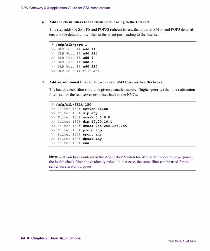
VPN Gateway 6.0 Application Guide for SSL Acceleration
6. Add the client filters to the client port leading to the Internet.
This step adds the SMTPS and POP3S redirect filters, the optional SMTP and POP3 deny fil-ters and the default allow filter to the client port leading to the Internet.
7. Add an additional filter to allow for real SMTP server health checks.
The health check filter should be given a smaller number (higher priority) than the redirection filters set for the real server responses back to the NVGs.
NOTE – If you have configured the Application Switch for Web server accelerator purposes, the health check filter above already exists. In that case, the same filter can be used for mail server accelerator purposes.
# /cfg/slb/port 1>> SLB Port 1# add 110>> SLB Port 1# add 120>> SLB Port 1# add 4>> SLB Port 1# add 5>> SLB Port 1# add 224>> SLB Port 1# filt ena
# /cfg/slb/filt 150>> Filter 150# action allow>> Filter 150# sip any>> Filter 150# smask 0.0.0.0>> Filter 150# dip 10.20.10.1>> Filter 150# dmask 255.255.255.255>> Filter 150# proto tcp>> Filter 150# sport any>> Filter 150# dport any>> Filter 150# ena
216370-D, April 200664 Chapter 2: Basic Applications
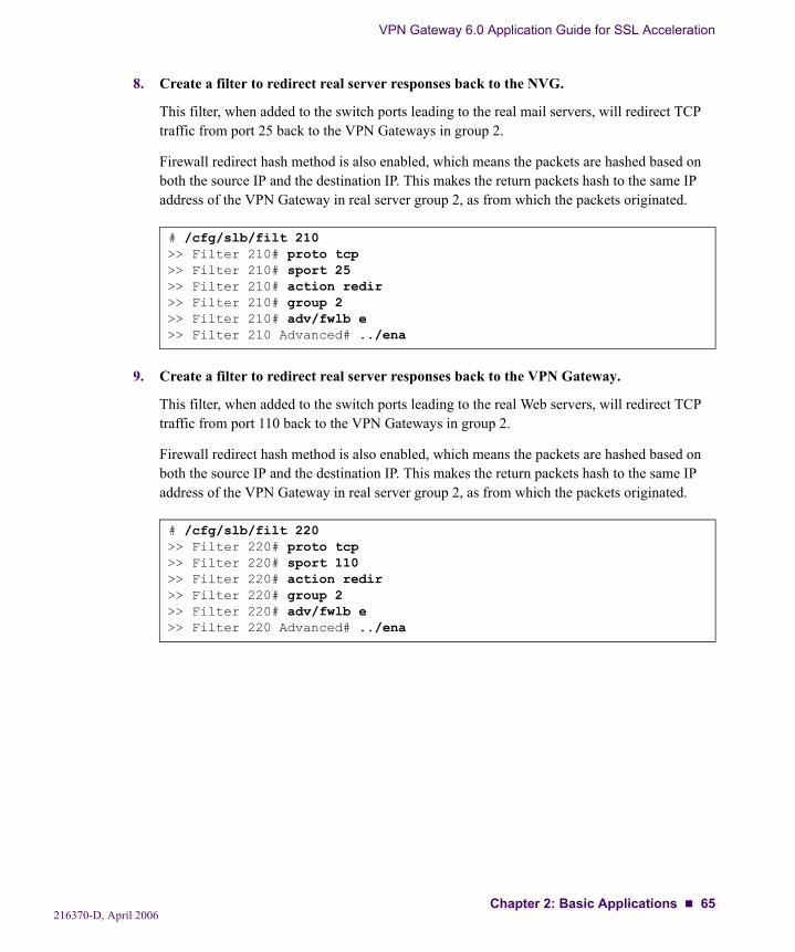
VPN Gateway 6.0 Application Guide for SSL Acceleration
8. Create a filter to redirect real server responses back to the NVG.
This filter, when added to the switch ports leading to the real mail servers, will redirect TCP traffic from port 25 back to the VPN Gateways in group 2.
Firewall redirect hash method is also enabled, which means the packets are hashed based on both the source IP and the destination IP. This makes the return packets hash to the same IP address of the VPN Gateway in real server group 2, as from which the packets originated.
9. Create a filter to redirect real server responses back to the VPN Gateway.
This filter, when added to the switch ports leading to the real Web servers, will redirect TCP traffic from port 110 back to the VPN Gateways in group 2.
Firewall redirect hash method is also enabled, which means the packets are hashed based on both the source IP and the destination IP. This makes the return packets hash to the same IP address of the VPN Gateway in real server group 2, as from which the packets originated.
# /cfg/slb/filt 210>> Filter 210# proto tcp>> Filter 210# sport 25>> Filter 210# action redir>> Filter 210# group 2>> Filter 210# adv/fwlb e>> Filter 210 Advanced# ../ena
# /cfg/slb/filt 220>> Filter 220# proto tcp>> Filter 220# sport 110>> Filter 220# action redir>> Filter 220# group 2>> Filter 220# adv/fwlb e>> Filter 220 Advanced# ../ena
216370-D, April 2006Chapter 2: Basic Applications 65
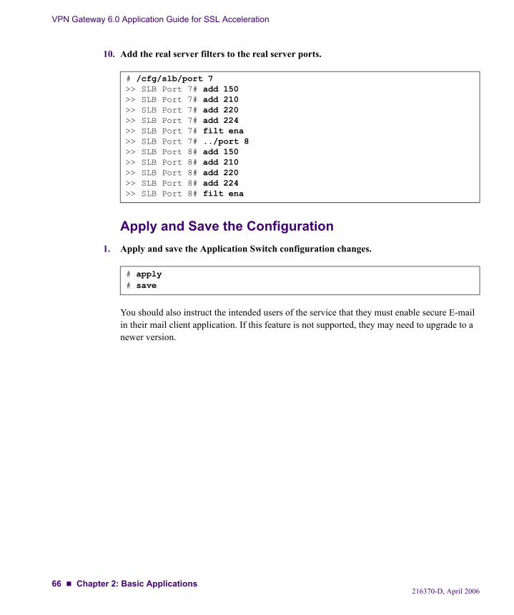
VPN Gateway 6.0 Application Guide for SSL Acceleration
10. Add the real server filters to the real server ports.
Apply and Save the Configuration1. Apply and save the Application Switch configuration changes.
You should also instruct the intended users of the service that they must enable secure E-mail in their mail client application. If this feature is not supported, they may need to upgrade to a newer version.
# /cfg/slb/port 7>> SLB Port 7# add 150>> SLB Port 7# add 210>> SLB Port 7# add 220>> SLB Port 7# add 224>> SLB Port 7# filt ena>> SLB Port 7# ../port 8>> SLB Port 8# add 150>> SLB Port 8# add 210>> SLB Port 8# add 220>> SLB Port 8# add 224>> SLB Port 8# filt ena
# apply# save
216370-D, April 200666 Chapter 2: Basic Applications
CHAPTER 3Web Server Accelerator with End to End Encryption
This chapter describes how to configure the Nortel VPN Gateway (NVG) to be used as a Web server accelerator, where the information exchanged on the network segment between the NVGs and the real Web servers is encrypted. Such a configuration can be desirable, or even required, in many high security environments such as the financial, medical, insurance, corpo-rate, or government sector. For a description of the basic operation of the VPN Gateway when used as a Web server accelerator with endpoint encryption, see page 20.
However, only setting up a new SSL connection between the VPN Gateway and the backend servers would degrade the performance of the backend servers considerably when end to end encryption is involved, and the benefits of using the NVG as an offload device would be impaired. In order to alleviate the performance degradation, three different methods that inter-act with each other are part of the NVG:
“SSL Connect” on page 68“Connection Pooling” on page 68“Load Balancing” on page 69
216370-D, April 200667
VPN Gateway 6.0 Application Guide for SSL Acceleration
Concepts
SSL ConnectSSL Connect enables the VPN Gateway to set up an SSL connection to the backend servers, while at the same time terminating the SSL connection to the client. This provides the means for authenticating the backend server and securing the information that is exchanged also on this network segment. Because a new SSL connection is established between the VPN Gate-way and the backend server, a lighter encryption algorithm can be used on this more protected network segment in order to improve performance. For server authentication purposes, you can generate a server certificate using the CLI on the VPN Gateway, and then install the certificate and the private key on the backend server. For client authentication purposes, you can generate a client certificate on the VPN Gateway, and then install the client certificate and the private key on the VPN Gateway. Provided the backend server is configured to require a client certifi-cate, the VPN Gateway will present the configured client certificate.
Furthermore, since the VPN Gateway will be acting as a client towards the backend server, the NVG will always try to reuse previously established SSL sessions. The SSL session reuse attempts will be successful, since the backend server recognizes the VPN Gateway as a client that connects repeatedly. SSL session reuse between the VPN Gateway and the backend server helps in lowering the overhead involved in performing a full SSL handshake.
Connection PoolingConnection Pooling enables the VPN Gateway to reuse the server side of a socket for a future client request. Sockets can be pooled and reused when either the client closes its end of the socket, or when a specific time frame with no traffic on the client socket has elapsed. Sockets are only pooled when all the HTTP requests that were received on the client side socket have been fully replied to on the server side socket. If these criteria are met, the pooling occurs when the proxy is just about to close the server side socket. The next time a client initiates a request, a server side socket available in the pool can be reused instead of establishing a new socket with all the overhead involved. One pool of server side sockets is maintained for each backend server that responds positively to the health checking performed at regular intervals. This mechanism improves performance and enables the VPN Gateway to handle more connections per second when SSL connect is enabled (for end to end encryption purposes).
216370-D, April 200668 Chapter 3: Web Server Accelerator with End to End Encryption
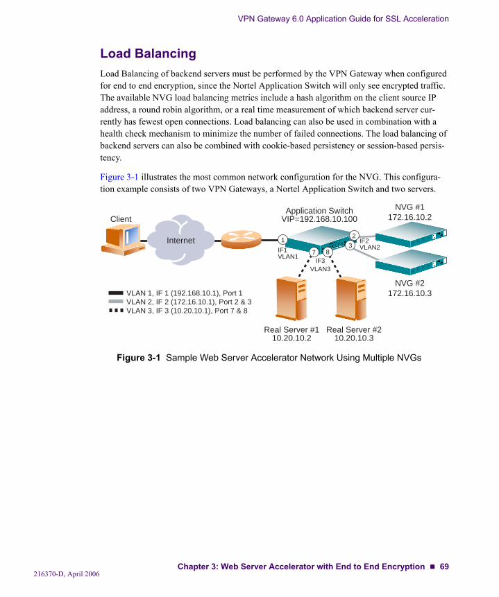
VPN Gateway 6.0 Application Guide for SSL Acceleration
Load BalancingLoad Balancing of backend servers must be performed by the VPN Gateway when configured for end to end encryption, since the Nortel Application Switch will only see encrypted traffic. The available NVG load balancing metrics include a hash algorithm on the client source IP address, a round robin algorithm, or a real time measurement of which backend server cur-rently has fewest open connections. Load balancing can also be used in combination with a health check mechanism to minimize the number of failed connections. The load balancing of backend servers can also be combined with cookie-based persistency or session-based persis-tency.
Figure 3-1 illustrates the most common network configuration for the NVG. This configura-tion example consists of two VPN Gateways, a Nortel Application Switch and two servers.
Figure 3-1 Sample Web Server Accelerator Network Using Multiple NVGs
Internet
ClientApplication Switch
VIP=192.168.10.100
Real Server #110.20.10.2
Real Server #210.20.10.3
13
2
87
NVG #1172.16.10.2
NVG #2172.16.10.3
IF3VLAN3
IF2VLAN2IF1
VLAN1
VLAN 1, IF 1 (192.168.10.1), Port 1VLAN 2, IF 2 (172.16.10.1), Port 2 & 3VLAN 3, IF 3 (10.20.10.1), Port 7 & 8
216370-D, April 2006Chapter 3: Web Server Accelerator with End to End Encryption 69
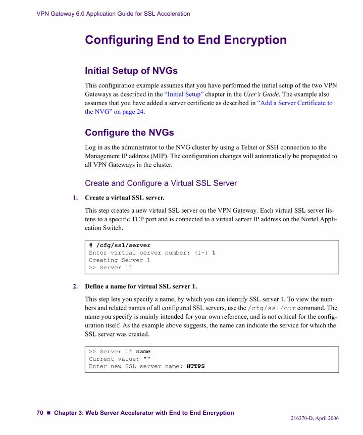
VPN Gateway 6.0 Application Guide for SSL Acceleration
Configuring End to End Encryption
Initial Setup of NVGsThis configuration example assumes that you have performed the initial setup of the two VPN Gateways as described in the “Initial Setup” chapter in the User’s Guide. The example also assumes that you have added a server certificate as described in “Add a Server Certificate to the NVG” on page 24.
Configure the NVGsLog in as the administrator to the NVG cluster by using a Telnet or SSH connection to the Management IP address (MIP). The configuration changes will automatically be propagated to all VPN Gateways in the cluster.
Create and Configure a Virtual SSL Server
1. Create a virtual SSL server.
This step creates a new virtual SSL server on the VPN Gateway. Each virtual SSL server lis-tens to a specific TCP port and is connected to a virtual server IP address on the Nortel Appli-cation Switch.
2. Define a name for virtual SSL server 1.
This step lets you specify a name, by which you can identify SSL server 1. To view the num-bers and related names of all configured SSL servers, use the /cfg/ssl/cur command. The name you specify is mainly intended for your own reference, and is not critical for the config-uration itself. As the example above suggests, the name can indicate the service for which the SSL server was created.
# /cfg/ssl/serverEnter virtual server number: (1-) 1Creating Server 1>> Server 1#
>> Server 1# nameCurrent value: ""Enter new SSL server name: HTTPS
216370-D, April 200670 Chapter 3: Web Server Accelerator with End to End Encryption
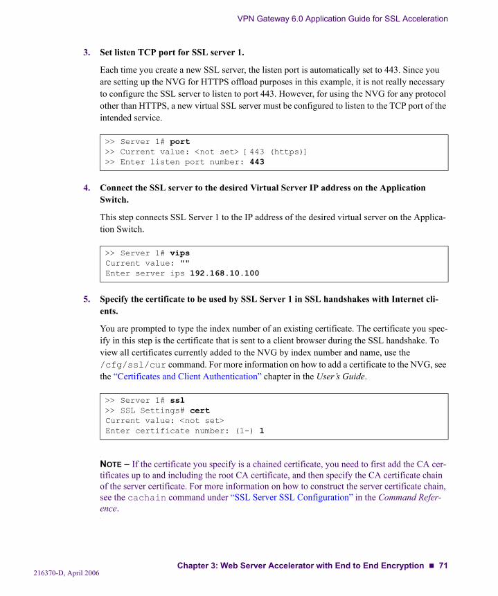
VPN Gateway 6.0 Application Guide for SSL Acceleration
3. Set listen TCP port for SSL server 1.
Each time you create a new SSL server, the listen port is automatically set to 443. Since you are setting up the NVG for HTTPS offload purposes in this example, it is not really necessary to configure the SSL server to listen to port 443. However, for using the NVG for any protocol other than HTTPS, a new virtual SSL server must be configured to listen to the TCP port of the intended service.
4. Connect the SSL server to the desired Virtual Server IP address on the Application Switch.
This step connects SSL Server 1 to the IP address of the desired virtual server on the Applica-tion Switch.
5. Specify the certificate to be used by SSL Server 1 in SSL handshakes with Internet cli-ents.
You are prompted to type the index number of an existing certificate. The certificate you spec-ify in this step is the certificate that is sent to a client browser during the SSL handshake. To view all certificates currently added to the NVG by index number and name, use the /cfg/ssl/cur command. For more information on how to add a certificate to the NVG, see the “Certificates and Client Authentication” chapter in the User’s Guide.
NOTE – If the certificate you specify is a chained certificate, you need to first add the CA cer-tificates up to and including the root CA certificate, and then specify the CA certificate chain of the server certificate. For more information on how to construct the server certificate chain, see the cachain command under “SSL Server SSL Configuration” in the Command Refer-ence.
>> Server 1# port>> Current value: <not set> [443 (https)]>> Enter listen port number: 443
>> Server 1# vipsCurrent value: ""Enter server ips 192.168.10.100
>> Server 1# ssl>> SSL Settings# certCurrent value: <not set>Enter certificate number: (1-) 1
216370-D, April 2006Chapter 3: Web Server Accelerator with End to End Encryption 71
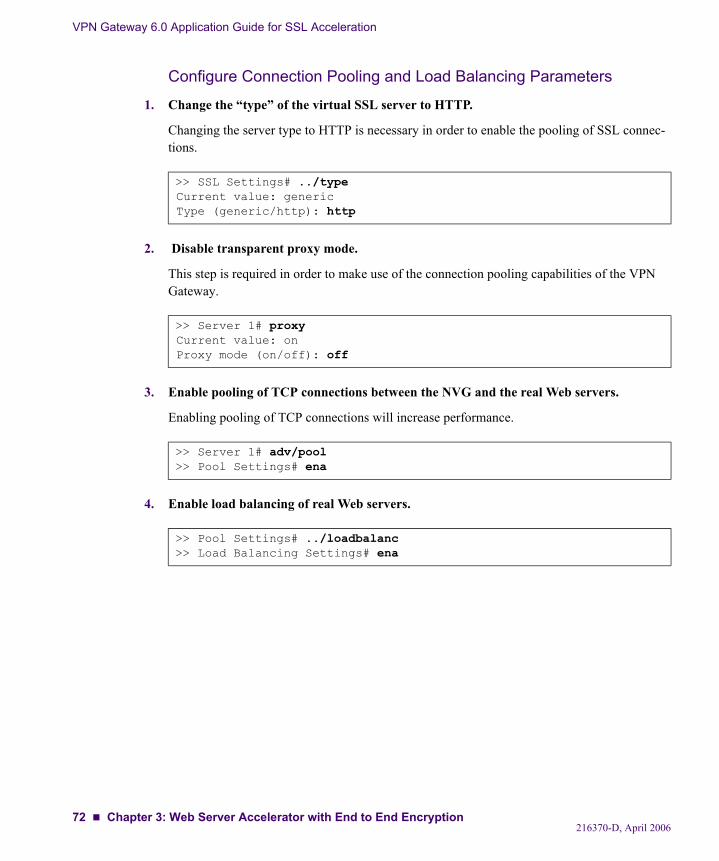
VPN Gateway 6.0 Application Guide for SSL Acceleration
Configure Connection Pooling and Load Balancing Parameters
1. Change the “type” of the virtual SSL server to HTTP.
Changing the server type to HTTP is necessary in order to enable the pooling of SSL connec-tions.
2. Disable transparent proxy mode.
This step is required in order to make use of the connection pooling capabilities of the VPN Gateway.
3. Enable pooling of TCP connections between the NVG and the real Web servers.
Enabling pooling of TCP connections will increase performance.
4. Enable load balancing of real Web servers.
>> SSL Settings# ../typeCurrent value: genericType (generic/http): http
>> Server 1# proxyCurrent value: onProxy mode (on/off): off
>> Server 1# adv/pool>> Pool Settings# ena
>> Pool Settings# ../loadbalanc>> Load Balancing Settings# ena
216370-D, April 200672 Chapter 3: Web Server Accelerator with End to End Encryption
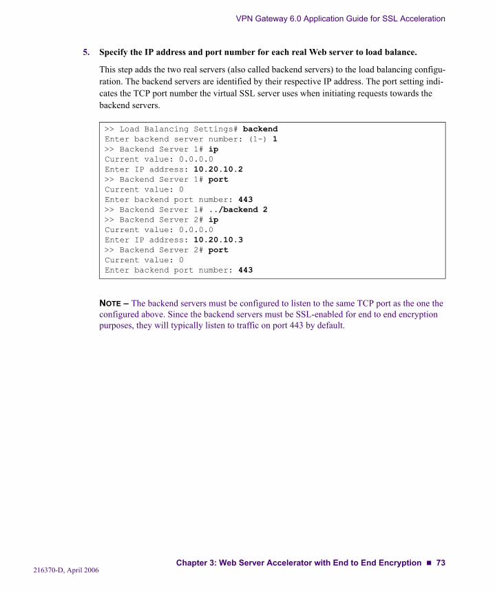
VPN Gateway 6.0 Application Guide for SSL Acceleration
5. Specify the IP address and port number for each real Web server to load balance.
This step adds the two real servers (also called backend servers) to the load balancing configu-ration. The backend servers are identified by their respective IP address. The port setting indi-cates the TCP port number the virtual SSL server uses when initiating requests towards the backend servers.
NOTE – The backend servers must be configured to listen to the same TCP port as the one the configured above. Since the backend servers must be SSL-enabled for end to end encryption purposes, they will typically listen to traffic on port 443 by default.
>> Load Balancing Settings# backendEnter backend server number: (1-) 1>> Backend Server 1# ipCurrent value: 0.0.0.0Enter IP address: 10.20.10.2>> Backend Server 1# portCurrent value: 0Enter backend port number: 443>> Backend Server 1# ../backend 2>> Backend Server 2# ipCurrent value: 0.0.0.0Enter IP address: 10.20.10.3>> Backend Server 2# portCurrent value: 0Enter backend port number: 443
216370-D, April 2006Chapter 3: Web Server Accelerator with End to End Encryption 73
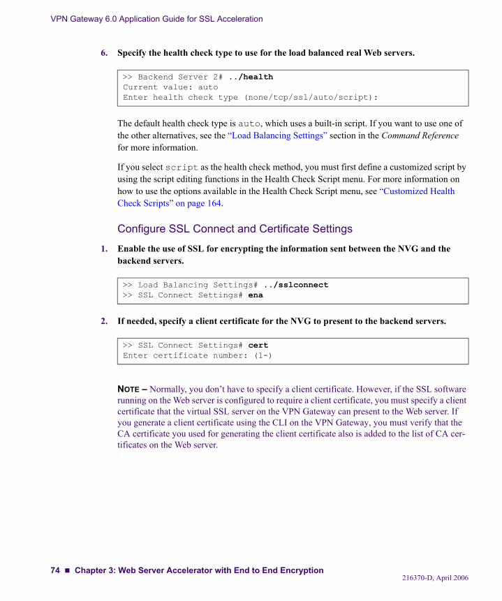
VPN Gateway 6.0 Application Guide for SSL Acceleration
6. Specify the health check type to use for the load balanced real Web servers.
The default health check type is auto, which uses a built-in script. If you want to use one of the other alternatives, see the “Load Balancing Settings” section in the Command Reference for more information.
If you select script as the health check method, you must first define a customized script by using the script editing functions in the Health Check Script menu. For more information on how to use the options available in the Health Check Script menu, see “Customized Health Check Scripts” on page 164.
Configure SSL Connect and Certificate Settings
1. Enable the use of SSL for encrypting the information sent between the NVG and the backend servers.
2. If needed, specify a client certificate for the NVG to present to the backend servers.
NOTE – Normally, you don’t have to specify a client certificate. However, if the SSL software running on the Web server is configured to require a client certificate, you must specify a client certificate that the virtual SSL server on the VPN Gateway can present to the Web server. If you generate a client certificate using the CLI on the VPN Gateway, you must verify that the CA certificate you used for generating the client certificate also is added to the list of CA cer-tificates on the Web server.
>> Backend Server 2# ../healthCurrent value: autoEnter health check type (none/tcp/ssl/auto/script):
>> Load Balancing Settings# ../sslconnect>> SSL Connect Settings# ena
>> SSL Connect Settings# certEnter certificate number: (1-)
216370-D, April 200674 Chapter 3: Web Server Accelerator with End to End Encryption
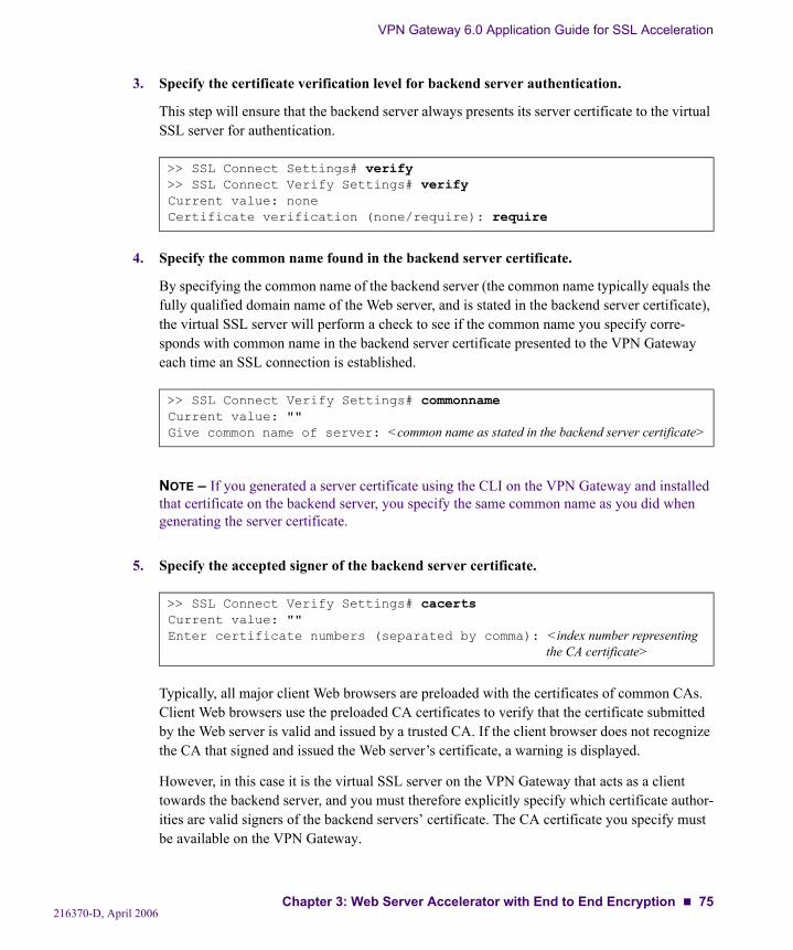
VPN Gateway 6.0 Application Guide for SSL Acceleration
3. Specify the certificate verification level for backend server authentication.
This step will ensure that the backend server always presents its server certificate to the virtual SSL server for authentication.
4. Specify the common name found in the backend server certificate.
By specifying the common name of the backend server (the common name typically equals the fully qualified domain name of the Web server, and is stated in the backend server certificate), the virtual SSL server will perform a check to see if the common name you specify corre-sponds with common name in the backend server certificate presented to the VPN Gateway each time an SSL connection is established.
NOTE – If you generated a server certificate using the CLI on the VPN Gateway and installed that certificate on the backend server, you specify the same common name as you did when generating the server certificate.
5. Specify the accepted signer of the backend server certificate.
Typically, all major client Web browsers are preloaded with the certificates of common CAs. Client Web browsers use the preloaded CA certificates to verify that the certificate submitted by the Web server is valid and issued by a trusted CA. If the client browser does not recognize the CA that signed and issued the Web server’s certificate, a warning is displayed.
However, in this case it is the virtual SSL server on the VPN Gateway that acts as a client towards the backend server, and you must therefore explicitly specify which certificate author-ities are valid signers of the backend servers’ certificate. The CA certificate you specify must be available on the VPN Gateway.
>> SSL Connect Settings# verify>> SSL Connect Verify Settings# verifyCurrent value: noneCertificate verification (none/require): require
>> SSL Connect Verify Settings# commonnameCurrent value: ""Give common name of server: <common name as stated in the backend server certificate>
>> SSL Connect Verify Settings# cacertsCurrent value: ""Enter certificate numbers (separated by comma): <index number representing
the CA certificate>
216370-D, April 2006Chapter 3: Web Server Accelerator with End to End Encryption 75
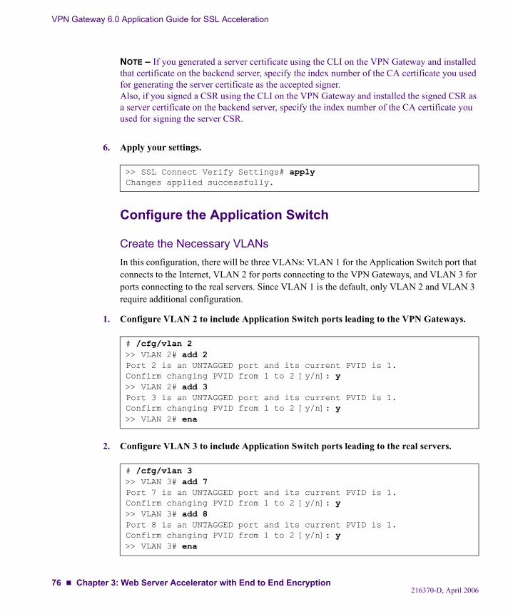
VPN Gateway 6.0 Application Guide for SSL Acceleration
NOTE – If you generated a server certificate using the CLI on the VPN Gateway and installed that certificate on the backend server, specify the index number of the CA certificate you used for generating the server certificate as the accepted signer.Also, if you signed a CSR using the CLI on the VPN Gateway and installed the signed CSR as a server certificate on the backend server, specify the index number of the CA certificate you used for signing the server CSR.
6. Apply your settings.
Configure the Application Switch
Create the Necessary VLANsIn this configuration, there will be three VLANs: VLAN 1 for the Application Switch port that connects to the Internet, VLAN 2 for ports connecting to the VPN Gateways, and VLAN 3 for ports connecting to the real servers. Since VLAN 1 is the default, only VLAN 2 and VLAN 3 require additional configuration.
1. Configure VLAN 2 to include Application Switch ports leading to the VPN Gateways.
2. Configure VLAN 3 to include Application Switch ports leading to the real servers.
>> SSL Connect Verify Settings# applyChanges applied successfully.
# /cfg/vlan 2>> VLAN 2# add 2Port 2 is an UNTAGGED port and its current PVID is 1.Confirm changing PVID from 1 to 2 [y/n]: y>> VLAN 2# add 3Port 3 is an UNTAGGED port and its current PVID is 1.Confirm changing PVID from 1 to 2 [y/n]: y>> VLAN 2# ena
# /cfg/vlan 3>> VLAN 3# add 7Port 7 is an UNTAGGED port and its current PVID is 1.Confirm changing PVID from 1 to 2 [y/n]: y>> VLAN 3# add 8Port 8 is an UNTAGGED port and its current PVID is 1.Confirm changing PVID from 1 to 2 [y/n]: y>> VLAN 3# ena
216370-D, April 200676 Chapter 3: Web Server Accelerator with End to End Encryption
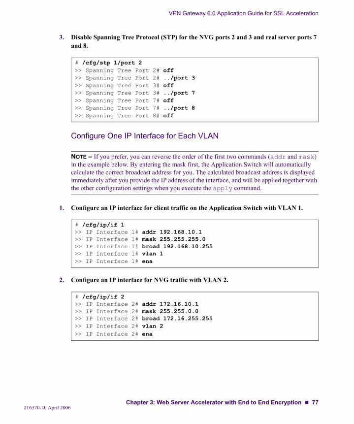
VPN Gateway 6.0 Application Guide for SSL Acceleration
3. Disable Spanning Tree Protocol (STP) for the NVG ports 2 and 3 and real server ports 7 and 8.
Configure One IP Interface for Each VLAN
NOTE – If you prefer, you can reverse the order of the first two commands (addr and mask) in the example below. By entering the mask first, the Application Switch will automatically calculate the correct broadcast address for you. The calculated broadcast address is displayed immediately after you provide the IP address of the interface, and will be applied together with the other configuration settings when you execute the apply command.
1. Configure an IP interface for client traffic on the Application Switch with VLAN 1.
2. Configure an IP interface for NVG traffic with VLAN 2.
# /cfg/stp 1/port 2>> Spanning Tree Port 2# off>> Spanning Tree Port 2# ../port 3>> Spanning Tree Port 3# off>> Spanning Tree Port 3# ../port 7>> Spanning Tree Port 7# off>> Spanning Tree Port 7# ../port 8>> Spanning Tree Port 8# off
# /cfg/ip/if 1>> IP Interface 1# addr 192.168.10.1>> IP Interface 1# mask 255.255.255.0>> IP Interface 1# broad 192.168.10.255>> IP Interface 1# vlan 1>> IP Interface 1# ena
# /cfg/ip/if 2>> IP Interface 2# addr 172.16.10.1>> IP Interface 2# mask 255.255.0.0>> IP Interface 2# broad 172.16.255.255>> IP Interface 2# vlan 2>> IP Interface 2# ena
216370-D, April 2006Chapter 3: Web Server Accelerator with End to End Encryption 77
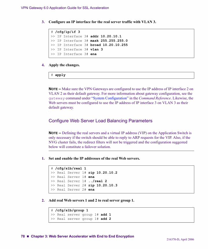
VPN Gateway 6.0 Application Guide for SSL Acceleration
3. Configure an IP interface for the real server traffic with VLAN 3.
4. Apply the changes.
NOTE – Make sure the VPN Gateways are configured to use the IP address of IP interface 2 on VLAN 2 as their default gateway. For more information about gateway configuration, see the gateway command under “System Configuration” in the Command Reference. Likewise, the Web servers must be configured to use the IP address of IP interface 3 on VLAN 3 as their default gateway.
Configure Web Server Load Balancing Parameters
NOTE – Defining the real servers and a virtual IP address (VIP) on the Application Switch is only necessary if the switch should be able to reply to ARP requests for the VIP. Also, if the NVG cluster fails, the redirect filters will not be triggered and the configuration suggested below will constitute a failover solution.
1. Set and enable the IP addresses of the real Web servers.
2. Add real Web servers 1 and 2 to real server group 1.
# /cfg/ip/if 3>> IP Interface 3# addr 10.20.10.1>> IP Interface 3# mask 255.255.255.0>> IP Interface 3# broad 10.20.10.255>> IP Interface 3# vlan 3>> IP Interface 3# ena
# apply
# /cfg/slb/real 1>> Real Server 1# rip 10.20.10.2>> Real Server 1# ena>> Real Server 1# ../real 2>> Real Server 2# rip 10.20.10.3>> Real Server 2# ena
# /cfg/slb/group 1>> Real server group 1# add 1>> Real server group 1# add 2
216370-D, April 200678 Chapter 3: Web Server Accelerator with End to End Encryption
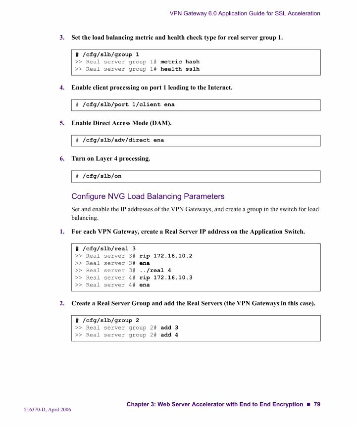
VPN Gateway 6.0 Application Guide for SSL Acceleration
3. Set the load balancing metric and health check type for real server group 1.
4. Enable client processing on port 1 leading to the Internet.
5. Enable Direct Access Mode (DAM).
6. Turn on Layer 4 processing.
Configure NVG Load Balancing ParametersSet and enable the IP addresses of the VPN Gateways, and create a group in the switch for load balancing.
1. For each VPN Gateway, create a Real Server IP address on the Application Switch.
2. Create a Real Server Group and add the Real Servers (the VPN Gateways in this case).
# /cfg/slb/group 1>> Real server group 1# metric hash>> Real server group 1# health sslh
# /cfg/slb/port 1/client ena
# /cfg/slb/adv/direct ena
# /cfg/slb/on
# /cfg/slb/real 3>> Real server 3# rip 172.16.10.2>> Real server 3# ena>> Real server 3# ../real 4>> Real server 4# rip 172.16.10.3>> Real server 4# ena
# /cfg/slb/group 2>> Real server group 2# add 3>> Real server group 2# add 4
216370-D, April 2006Chapter 3: Web Server Accelerator with End to End Encryption 79
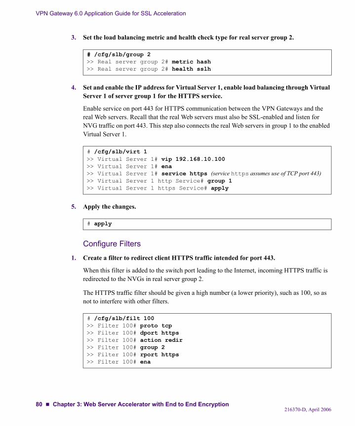
VPN Gateway 6.0 Application Guide for SSL Acceleration
3. Set the load balancing metric and health check type for real server group 2.
4. Set and enable the IP address for Virtual Server 1, enable load balancing through Virtual Server 1 of server group 1 for the HTTPS service.
Enable service on port 443 for HTTPS communication between the VPN Gateways and the real Web servers. Recall that the real Web servers must also be SSL-enabled and listen for NVG traffic on port 443. This step also connects the real Web servers in group 1 to the enabled Virtual Server 1.
5. Apply the changes.
Configure Filters
1. Create a filter to redirect client HTTPS traffic intended for port 443.
When this filter is added to the switch port leading to the Internet, incoming HTTPS traffic is redirected to the NVGs in real server group 2.
The HTTPS traffic filter should be given a high number (a lower priority), such as 100, so as not to interfere with other filters.
# /cfg/slb/group 2>> Real server group 2# metric hash>> Real server group 2# health sslh
# /cfg/slb/virt 1>> Virtual Server 1# vip 192.168.10.100>> Virtual Server 1# ena>> Virtual Server 1# service https (service https assumes use of TCP port 443)>> Virtual Server 1 http Service# group 1>> Virtual Server 1 https Service# apply
# apply
# /cfg/slb/filt 100>> Filter 100# proto tcp>> Filter 100# dport https>> Filter 100# action redir>> Filter 100# group 2>> Filter 100# rport https>> Filter 100# ena
216370-D, April 200680 Chapter 3: Web Server Accelerator with End to End Encryption
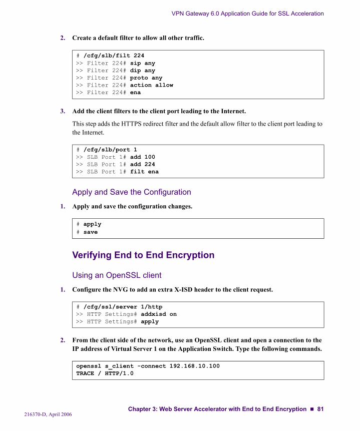
VPN Gateway 6.0 Application Guide for SSL Acceleration
2. Create a default filter to allow all other traffic.
3. Add the client filters to the client port leading to the Internet.
This step adds the HTTPS redirect filter and the default allow filter to the client port leading to the Internet.
Apply and Save the Configuration
1. Apply and save the configuration changes.
Verifying End to End Encryption
Using an OpenSSL client
1. Configure the NVG to add an extra X-ISD header to the client request.
2. From the client side of the network, use an OpenSSL client and open a connection to the IP address of Virtual Server 1 on the Application Switch. Type the following commands.
# /cfg/slb/filt 224>> Filter 224# sip any>> Filter 224# dip any>> Filter 224# proto any>> Filter 224# action allow>> Filter 224# ena
# /cfg/slb/port 1>> SLB Port 1# add 100>> SLB Port 1# add 224>> SLB Port 1# filt ena
# apply# save
# /cfg/ssl/server 1/http>> HTTP Settings# addxisd on>> HTTP Settings# apply
openssl s_client -connect 192.168.10.100TRACE / HTTP/1.0
216370-D, April 2006Chapter 3: Web Server Accelerator with End to End Encryption 81
VPN Gateway 6.0 Application Guide for SSL Acceleration
3. In the response, look for the X-ISD header. The output should resemble the following example.
Note that the type=https-https entry that appears at the end of the X-ISD header shows https both for the incoming client request, and for the request that VPN Gateway #1 (with IP address 172.16.10.2) initiated to backend server #2 (with IP address 10.20.10.3). This entry verifies that end to end encryption has been performed.
Using a Secure Telnet client
1. From the client side of the network, use a TelnetS (Secure Telnet) client and open a con-nection to the IP address of Virtual Server 1 on the Application Switch.
192.168.10.100
2. Type the following command in your TelnetS client.
3. In the response from the backend server, look for the Server header. The output should resemble the following example.
The Server header contains information about the SSL software running on the backend server, which enables the VPN Gateway to transmit encrypted requests.
Host: 192.168.10.100Via: 1.0 192.168.10.100 Alteon iSD-SSL/6.0 X-ISD: 172.16.10.2 10.20.10.3 index=1; pool=on; lb=all-roundrobin; type=https-httpsX-SSL: decrypted=true, ciphers="TLSv1/SSLv3 DES-CBC3-SHA"
GET / HTTP/1.0
HTTP/1.1 200 OKDate: Thu, 15 Dec 2006 10:40:06 GMTServer: Apache/1.3.20 (Unix) mod_ssl/2.8.4 OpenSSL/0.9.6Content-Type: message/httpConnection: closeVia: 1.1 192.168.10.100 Alteon iSD-SSL/6.0
216370-D, April 200682 Chapter 3: Web Server Accelerator with End to End Encryption
CHAPTER 4Web Server Accelerator with Multiple Networks in Cluster
This chapter provides the configuration details for creating a Web server accelerator solution with the following characteristics:
Fully redundant system with four Nortel Application Switches running in active-standby mode and a cluster of two Nortel VPN Gateways (NVGs). There is no single point-of-fail-ure.
Encrypted traffic that is separated from non-encrypted traffic and management traffic by configuring two different IP networks on the VPN Gateways.
Higher level of security for the NVG cluster, since management access is only allowed via the internal trusted IP network.
216370-D, April 200683
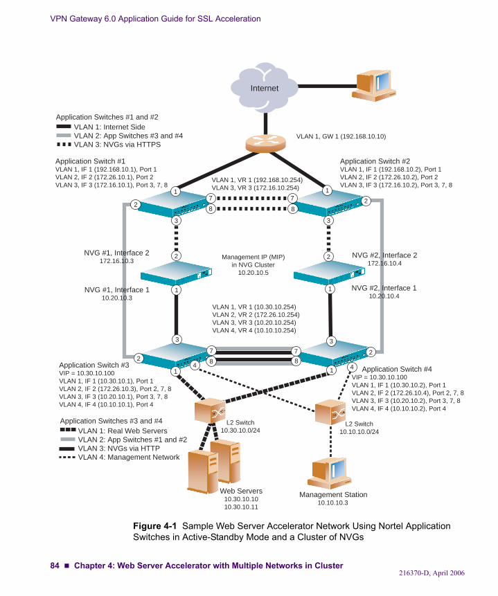
VPN Gateway 6.0 Application Guide for SSL Acceleration
Figure 4-1 Sample Web Server Accelerator Network Using Nortel Application Switches in Active-Standby Mode and a Cluster of NVGs
Application Switch #1VLAN 1, IF 1 (192.168.10.1), Port 1VLAN 2, IF 2 (172.26.10.1), Port 2VLAN 3, IF 3 (172.16.10.1), Port 3, 7, 8
Application Switch #2VLAN 1, IF 1 (192.168.10.2), Port 1VLAN 2, IF 2 (172.26.10.2), Port 2VLAN 3, IF 3 (172.16.10.2), Port 3, 7, 8
VLAN 1, VR 1 (192.168.10.254)VLAN 3, VR 3 (172.16.10.254)
L2 Switch10.30.10.0/24
Internet
Application Switch #3VIP = 10.30.10.100VLAN 1, IF 1 (10.30.10.1), Port 1VLAN 2, IF 2 (172.26.10.3), Port 2, 7, 8VLAN 3, IF 3 (10.20.10.1), Port 3, 7, 8VLAN 4, IF 4 (10.10.10.1), Port 4
Application Switch #4VIP = 10.30.10.100VLAN 1, IF 1 (10.30.10.2), Port 1VLAN 2, IF 2 (172.26.10.4), Port 2, 7, 8VLAN 3, IF 3 (10.20.10.2), Port 3, 7, 8VLAN 4, IF 4 (10.10.10.2), Port 4
VLAN 1, VR 1 (10.30.10.254)VLAN 2, VR 2 (172.26.10.254)VLAN 3, VR 3 (10.20.10.254)VLAN 4, VR 4 (10.10.10.254)
VLAN 1: Internet SideVLAN 2: App Switches #3 and #4VLAN 3: NVGs via HTTPS
Application Switches #1 and #2
VLAN 1, GW 1 (192.168.10.10)
Management IP (MIP)in NVG Cluster
10.20.10.5
VLAN 1: Real Web ServersVLAN 2: App Switches #1 and #2VLAN 3: NVGs via HTTPVLAN 4: Management Network
Application Switches #3 and #4
3
2
3
2
2
NVG #1, Interface 2172.16.10.3
NVG #1, Interface 110.20.10.3
2
2
NVG #2, Interface 2172.16.10.4
NVG #2, Interface 110.20.10.4
2
1
3 3
1
L2 Switch10.10.10.0/24
8
7
8
711
Web Servers10.30.10.1010.30.10.11
4 4
Management Station 10.10.10.3
1 1
7 7
88
216370-D, April 200684 Chapter 4: Web Server Accelerator with Multiple Networks in Cluster
VPN Gateway 6.0 Application Guide for SSL Acceleration
Functional Description
NVG and Nortel Application SwitchThe two VPN Gateways in Figure 4-1 are both connected to a pair of Nortel Application Switches: Application Switch 1 and 2 connect to the Internet, whereas Application Switch 3 and 4 connect to the real Web servers and the management network.
Application Switches 1 and 2 are configured to perform load balancing of the VPN Gateways, to which all HTTPS client connection requests are redirected via a filter on Application Switch port 1. Application Switches 3 and 4, on the other hand, are configured to perform load balanc-ing of the real Web servers which receive both regular HTTP requests from Internet clients, and requests from the VPN Gateways for content that would have been encrypted had not the NVGs served as SSL offload devices. All other traffic coming from the Internet is blocked, using a combination of filters on switch port 1 on the Internet side Application Switches.
Application Switches 1 and 2 will send regular HTTP traffic over a direct (crossover) link to the virtual server configured on Application Switches 3 and 4, which in turn forwards the traf-fic to the load balanced real Web servers.
Application Switches 3 and 4 are configured to use the Return To Sender (RTS) feature, which ensures that a Web server response is always sent back through the same VPN Gateway that forwarded the client request (and terminated the SSL session in the process).
Optionally, a firewall or reversed proxy server could be used to forward the regular HTTP traf-fic from the Internet side Application Switches to the real Web servers (via Application Switches 3 and 4). However, this requires a different configuration and is beyond the scope of this example.
Health ChecksHealth checking is critical in any redundant solution. In this configuration, Application Switches 1 and 2 will perform health checks of Application Switches 3 and 4, respectively, and the health checks are forwarded via two HTTP proxy servers configured to run in non-trans-parent proxy mode in the NVG cluster. Since each VPN Gateway has a link to both an Appli-cation Switch on the Internet side and an Application Switch on the Web server side simultaneously, the health checking of Application Switches 3 and 4 includes verifying that both of these links are active.
216370-D, April 2006Chapter 4: Web Server Accelerator with Multiple Networks in Cluster 85
VPN Gateway 6.0 Application Guide for SSL Acceleration
The HTTP proxy servers on the VPN Gateways are used only for transmitting health checks to the HTTP responders that are enabled on Application Switches 3 and 4. The “health check” proxy servers are in effect regular virtual SSL servers, but where SSL and transparent proxy mode have been disabled.
Each VPN Gateway is configured with a health check proxy server that:
Listens to the physical IP address as configured for one VPN Gateway on Interface 2, which connects to an Application Switch on the Internet side. This is the VIP configura-tion setting.Initiates requests to one Application Switch on the server side, using the Application Switch’s IP interface address that connects to VLAN 3. This is the RIP configuration set-ting.Uses port 80 when listening to and initiating HTTP requests. These are the PORT and RPORT configuration settings.
Thus, when one of the Internet side Application Switches initiates a HTTP health check, the health check is transmitted to one of the NVG proxy servers. The proxy server forwards the HTTP request to its server side Application Switch. The HTTP responder that is enabled on the Application Switch sends a “HEALTH CHECK OK” reply back to the initiating Internet side Application Switch, using the return path through the same VPN Gateway (achieved by con-figuring the proxy servers to run in non-transparent mode).
Trunked Interswitch ConnectionThe connection between each pair of Application Switches (over port 7 and 8) plays a key role in this network solution, especially when it comes to the connection between Application Switches 3 and 4. Because unexpected routing behavior will result from a failed connection, you are strongly recommended to use port trunking on port 7 and 8 between each pair of Appli-cation Switches.
216370-D, April 200686 Chapter 4: Web Server Accelerator with Multiple Networks in Cluster
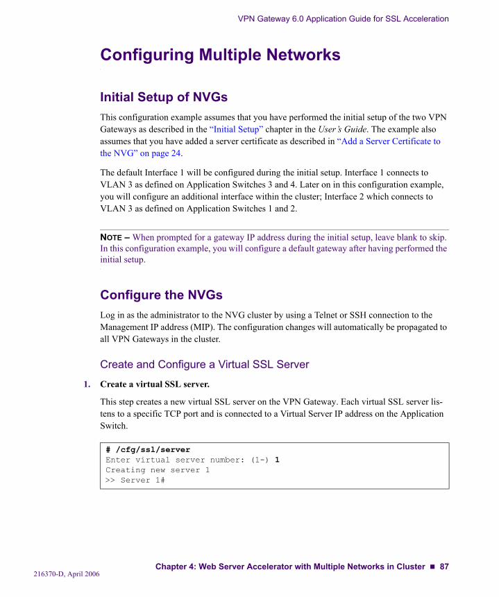
VPN Gateway 6.0 Application Guide for SSL Acceleration
Configuring Multiple Networks
Initial Setup of NVGsThis configuration example assumes that you have performed the initial setup of the two VPN Gateways as described in the “Initial Setup” chapter in the User’s Guide. The example also assumes that you have added a server certificate as described in “Add a Server Certificate to the NVG” on page 24.
The default Interface 1 will be configured during the initial setup. Interface 1 connects to VLAN 3 as defined on Application Switches 3 and 4. Later on in this configuration example, you will configure an additional interface within the cluster; Interface 2 which connects to VLAN 3 as defined on Application Switches 1 and 2.
NOTE – When prompted for a gateway IP address during the initial setup, leave blank to skip. In this configuration example, you will configure a default gateway after having performed the initial setup.
Configure the NVGsLog in as the administrator to the NVG cluster by using a Telnet or SSH connection to the Management IP address (MIP). The configuration changes will automatically be propagated to all VPN Gateways in the cluster.
Create and Configure a Virtual SSL Server
1. Create a virtual SSL server.
This step creates a new virtual SSL server on the VPN Gateway. Each virtual SSL server lis-tens to a specific TCP port and is connected to a Virtual Server IP address on the Application Switch.
# /cfg/ssl/serverEnter virtual server number: (1-) 1Creating new server 1>> Server 1#
216370-D, April 2006Chapter 4: Web Server Accelerator with Multiple Networks in Cluster 87
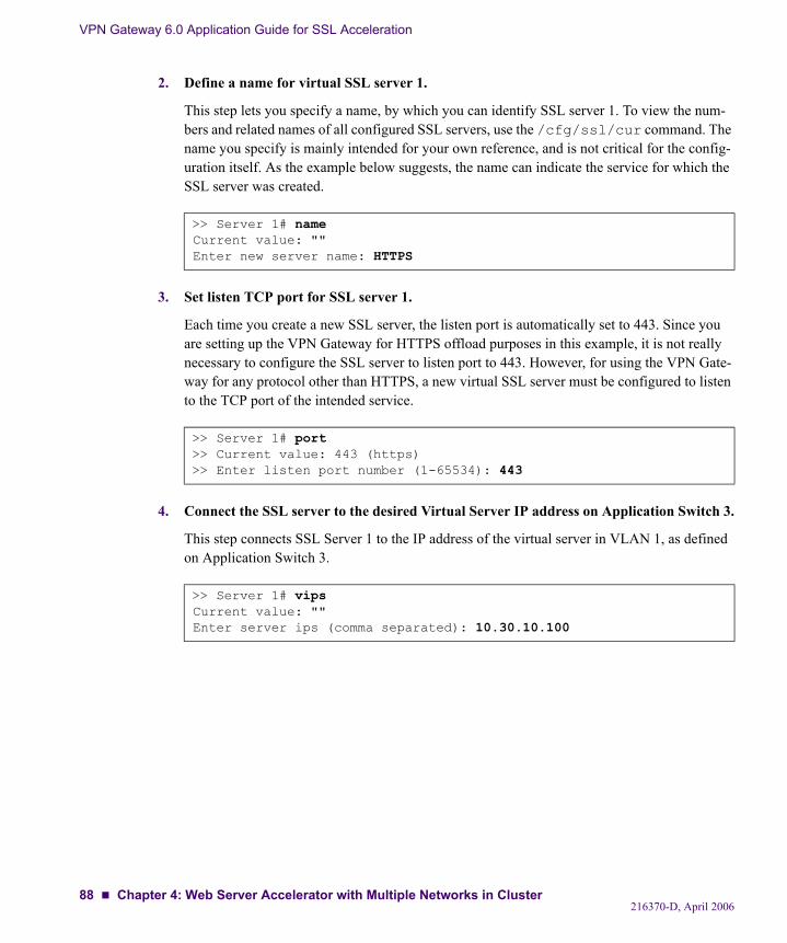
VPN Gateway 6.0 Application Guide for SSL Acceleration
2. Define a name for virtual SSL server 1.
This step lets you specify a name, by which you can identify SSL server 1. To view the num-bers and related names of all configured SSL servers, use the /cfg/ssl/cur command. The name you specify is mainly intended for your own reference, and is not critical for the config-uration itself. As the example below suggests, the name can indicate the service for which the SSL server was created.
3. Set listen TCP port for SSL server 1.
Each time you create a new SSL server, the listen port is automatically set to 443. Since you are setting up the VPN Gateway for HTTPS offload purposes in this example, it is not really necessary to configure the SSL server to listen port to 443. However, for using the VPN Gate-way for any protocol other than HTTPS, a new virtual SSL server must be configured to listen to the TCP port of the intended service.
4. Connect the SSL server to the desired Virtual Server IP address on Application Switch 3.
This step connects SSL Server 1 to the IP address of the virtual server in VLAN 1, as defined on Application Switch 3.
>> Server 1# nameCurrent value: ""Enter new server name: HTTPS
>> Server 1# port>> Current value: 443 (https)>> Enter listen port number (1-65534): 443
>> Server 1# vipsCurrent value: ""Enter server ips (comma separated): 10.30.10.100
216370-D, April 200688 Chapter 4: Web Server Accelerator with Multiple Networks in Cluster
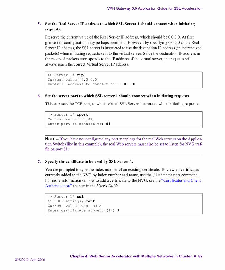
VPN Gateway 6.0 Application Guide for SSL Acceleration
5. Set the Real Server IP address to which SSL Server 1 should connect when initiating requests.
Preserve the current value of the Real Server IP address, which should be 0.0.0.0. At first glance this configuration may perhaps seem odd. However, by specifying 0.0.0.0 as the Real Server IP address, the SSL server is instructed to use the destination IP address (in the received packets) when initiating requests sent to the virtual server. Since the destination IP address in the received packets corresponds to the IP address of the virtual server, the requests will always reach the correct Virtual Server IP address.
6. Set the server port to which SSL server 1 should connect when initiating requests.
This step sets the TCP port, to which virtual SSL Server 1 connects when initiating requests.
NOTE – If you have not configured any port mappings for the real Web servers on the Applica-tion Switch (like in this example), the real Web servers must also be set to listen for NVG traf-fic on port 81.
7. Specify the certificate to be used by SSL Server 1.
You are prompted to type the index number of an existing certificate. To view all certificates currently added to the NVG by index number and name, use the /info/certs command. For more information on how to add a certificate to the NVG, see the “Certificates and Client Authentication” chapter in the User’s Guide.
>> Server 1# ripCurrent value: 0.0.0.0Enter IP address to connect to: 0.0.0.0
>> Server 1# rportCurrent value: 0 [81]Enter port to connect to: 81
>> Server 1# ssl>> SSL Settings# certCurrent value: <not set>Enter certificate number: (1-) 1
216370-D, April 2006Chapter 4: Web Server Accelerator with Multiple Networks in Cluster 89
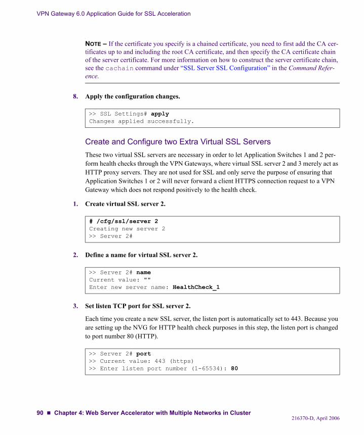
VPN Gateway 6.0 Application Guide for SSL Acceleration
NOTE – If the certificate you specify is a chained certificate, you need to first add the CA cer-tificates up to and including the root CA certificate, and then specify the CA certificate chain of the server certificate. For more information on how to construct the server certificate chain, see the cachain command under “SSL Server SSL Configuration” in the Command Refer-ence.
8. Apply the configuration changes.
Create and Configure two Extra Virtual SSL ServersThese two virtual SSL servers are necessary in order to let Application Switches 1 and 2 per-form health checks through the VPN Gateways, where virtual SSL server 2 and 3 merely act as HTTP proxy servers. They are not used for SSL and only serve the purpose of ensuring that Application Switches 1 or 2 will never forward a client HTTPS connection request to a VPN Gateway which does not respond positively to the health check.
1. Create virtual SSL server 2.
2. Define a name for virtual SSL server 2.
3. Set listen TCP port for SSL server 2.
Each time you create a new SSL server, the listen port is automatically set to 443. Because you are setting up the NVG for HTTP health check purposes in this step, the listen port is changed to port number 80 (HTTP).
>> SSL Settings# applyChanges applied successfully.
# /cfg/ssl/server 2Creating new server 2>> Server 2#
>> Server 2# nameCurrent value: ""Enter new server name: HealthCheck_1
>> Server 2# port>> Current value: 443 (https)>> Enter listen port number (1-65534): 80
216370-D, April 200690 Chapter 4: Web Server Accelerator with Multiple Networks in Cluster
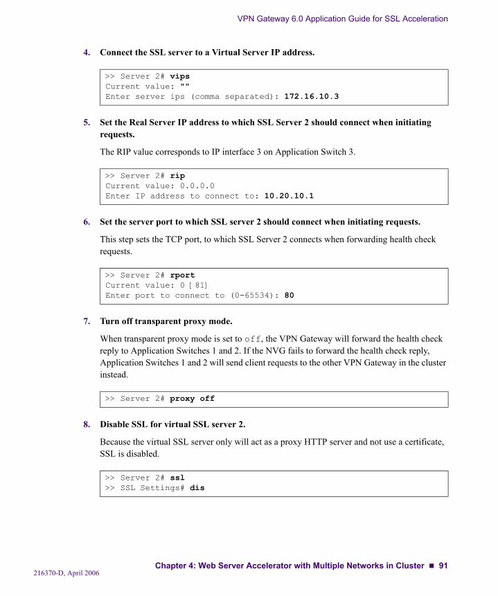
VPN Gateway 6.0 Application Guide for SSL Acceleration
4. Connect the SSL server to a Virtual Server IP address.
5. Set the Real Server IP address to which SSL Server 2 should connect when initiating requests.
The RIP value corresponds to IP interface 3 on Application Switch 3.
6. Set the server port to which SSL server 2 should connect when initiating requests.
This step sets the TCP port, to which SSL Server 2 connects when forwarding health check requests.
7. Turn off transparent proxy mode.
When transparent proxy mode is set to off, the VPN Gateway will forward the health check reply to Application Switches 1 and 2. If the NVG fails to forward the health check reply, Application Switches 1 and 2 will send client requests to the other VPN Gateway in the cluster instead.
8. Disable SSL for virtual SSL server 2.
Because the virtual SSL server only will act as a proxy HTTP server and not use a certificate, SSL is disabled.
>> Server 2# vipsCurrent value: ""Enter server ips (comma separated): 172.16.10.3
>> Server 2# ripCurrent value: 0.0.0.0Enter IP address to connect to: 10.20.10.1
>> Server 2# rportCurrent value: 0 [81]Enter port to connect to (0-65534): 80
>> Server 2# proxy off
>> Server 2# ssl>> SSL Settings# dis
216370-D, April 2006Chapter 4: Web Server Accelerator with Multiple Networks in Cluster 91
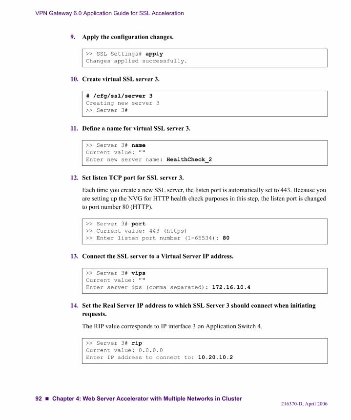
VPN Gateway 6.0 Application Guide for SSL Acceleration
9. Apply the configuration changes.
10. Create virtual SSL server 3.
11. Define a name for virtual SSL server 3.
12. Set listen TCP port for SSL server 3.
Each time you create a new SSL server, the listen port is automatically set to 443. Because you are setting up the NVG for HTTP health check purposes in this step, the listen port is changed to port number 80 (HTTP).
13. Connect the SSL server to a Virtual Server IP address.
14. Set the Real Server IP address to which SSL Server 3 should connect when initiating requests.
The RIP value corresponds to IP interface 3 on Application Switch 4.
>> SSL Settings# applyChanges applied successfully.
# /cfg/ssl/server 3Creating new server 3>> Server 3#
>> Server 3# nameCurrent value: ""Enter new server name: HealthCheck_2
>> Server 3# port>> Current value: 443 (https)>> Enter listen port number (1-65534): 80
>> Server 3# vipsCurrent value: ""Enter server ips (comma separated): 172.16.10.4
>> Server 3# ripCurrent value: 0.0.0.0Enter IP address to connect to: 10.20.10.2
216370-D, April 200692 Chapter 4: Web Server Accelerator with Multiple Networks in Cluster
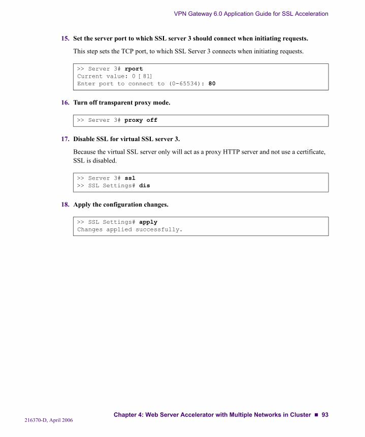
VPN Gateway 6.0 Application Guide for SSL Acceleration
15. Set the server port to which SSL server 3 should connect when initiating requests.
This step sets the TCP port, to which SSL Server 3 connects when initiating requests.
16. Turn off transparent proxy mode.
17. Disable SSL for virtual SSL server 3.
Because the virtual SSL server only will act as a proxy HTTP server and not use a certificate, SSL is disabled.
18. Apply the configuration changes.
>> Server 3# rportCurrent value: 0 [81]Enter port to connect to (0-65534): 80
>> Server 3# proxy off
>> Server 3# ssl>> SSL Settings# dis
>> SSL Settings# applyChanges applied successfully.
216370-D, April 2006Chapter 4: Web Server Accelerator with Multiple Networks in Cluster 93
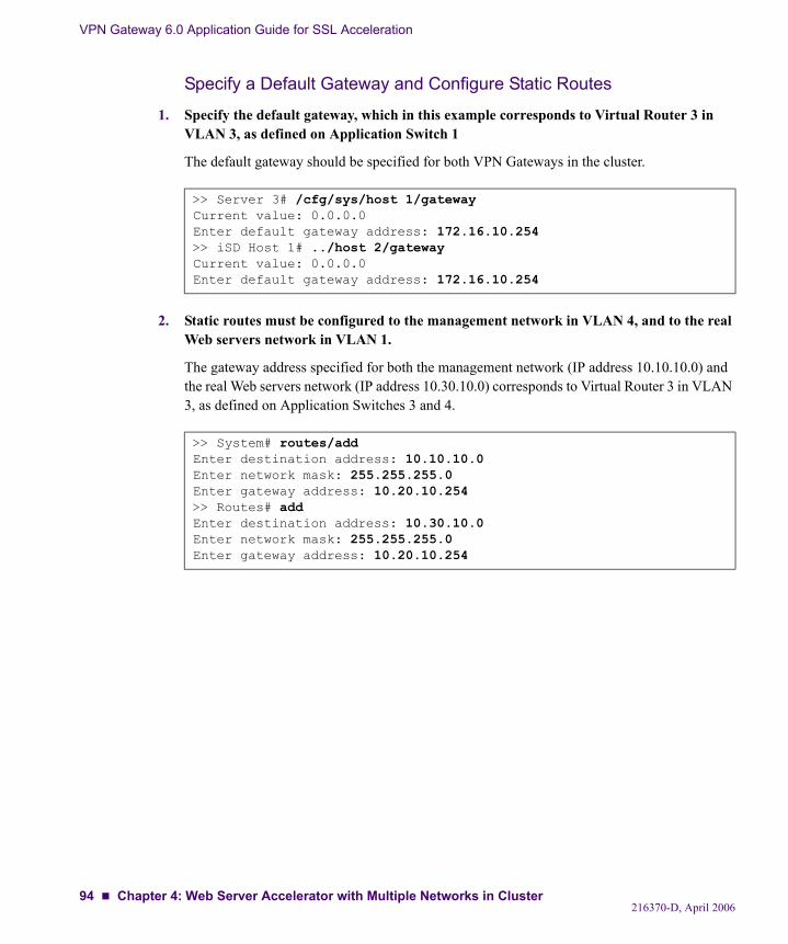
VPN Gateway 6.0 Application Guide for SSL Acceleration
Specify a Default Gateway and Configure Static Routes
1. Specify the default gateway, which in this example corresponds to Virtual Router 3 in VLAN 3, as defined on Application Switch 1
The default gateway should be specified for both VPN Gateways in the cluster.
2. Static routes must be configured to the management network in VLAN 4, and to the real Web servers network in VLAN 1.
The gateway address specified for both the management network (IP address 10.10.10.0) and the real Web servers network (IP address 10.30.10.0) corresponds to Virtual Router 3 in VLAN 3, as defined on Application Switches 3 and 4.
>> Server 3# /cfg/sys/host 1/gatewayCurrent value: 0.0.0.0Enter default gateway address: 172.16.10.254>> iSD Host 1# ../host 2/gatewayCurrent value: 0.0.0.0Enter default gateway address: 172.16.10.254
>> System# routes/addEnter destination address: 10.10.10.0Enter network mask: 255.255.255.0Enter gateway address: 10.20.10.254>> Routes# addEnter destination address: 10.30.10.0Enter network mask: 255.255.255.0Enter gateway address: 10.20.10.254
216370-D, April 200694 Chapter 4: Web Server Accelerator with Multiple Networks in Cluster
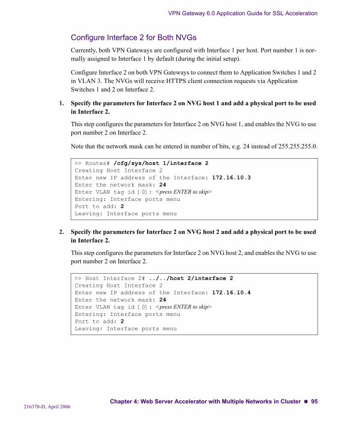
VPN Gateway 6.0 Application Guide for SSL Acceleration
Configure Interface 2 for Both NVGsCurrently, both VPN Gateways are configured with Interface 1 per host. Port number 1 is nor-mally assigned to Interface 1 by default (during the initial setup).
Configure Interface 2 on both VPN Gateways to connect them to Application Switches 1 and 2 in VLAN 3. The NVGs will receive HTTPS client connection requests via Application Switches 1 and 2 on Interface 2.
1. Specify the parameters for Interface 2 on NVG host 1 and add a physical port to be used in Interface 2.
This step configures the parameters for Interface 2 on NVG host 1, and enables the NVG to use port number 2 on Interface 2.
Note that the network mask can be entered in number of bits, e.g. 24 instead of 255.255.255.0.
2. Specify the parameters for Interface 2 on NVG host 2 and add a physical port to be used in Interface 2.
This step configures the parameters for Interface 2 on NVG host 2, and enables the NVG to use port number 2 on Interface 2.
>> Routes# /cfg/sys/host 1/interface 2Creating Host Interface 2Enter new IP address of the Interface: 172.16.10.3Enter the network mask: 24Enter VLAN tag id [0]: <press ENTER to skip>Entering: Interface ports menuPort to add: 2Leaving: Interface ports menu
>> Host Interface 2# ../../host 2/interface 2Creating Host Interface 2Enter new IP address of the Interface: 172.16.10.4Enter the network mask: 24Enter VLAN tag id [0]: <press ENTER to skip>Entering: Interface ports menuPort to add: 2Leaving: Interface ports menu
216370-D, April 2006Chapter 4: Web Server Accelerator with Multiple Networks in Cluster 95
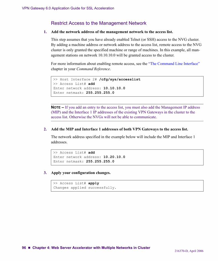
VPN Gateway 6.0 Application Guide for SSL Acceleration
Restrict Access to the Management Network
1. Add the network address of the management network to the access list.
This step assumes that you have already enabled Telnet (or SSH) access to the NVG cluster. By adding a machine address or network address to the access list, remote access to the NVG cluster is only granted the specified machine or range of machines. In this example, all man-agement stations on network 10.10.10.0 will be granted access to the cluster.
For more information about enabling remote access, see the “The Command Line Interface” chapter in your Command Reference.
NOTE – If you add an entry to the access list, you must also add the Management IP address (MIP) and the Interface 1 IP addresses of the existing VPN Gateways in the cluster to the access list. Otherwise the NVGs will not be able to communicate.
2. Add the MIP and Interface 1 addresses of both VPN Gateways to the access list.
The network address specified in the example below will include the MIP and Interface 1 addresses.
3. Apply your configuration changes.
>> Host Interface 2# /cfg/sys/accesslist>> Access List# addEnter network address: 10.10.10.0Enter netmask: 255.255.255.0
>> Access List# addEnter network address: 10.20.10.0Enter netmask: 255.255.255.0
>> Access List# applyChanges applied successfully.
216370-D, April 200696 Chapter 4: Web Server Accelerator with Multiple Networks in Cluster
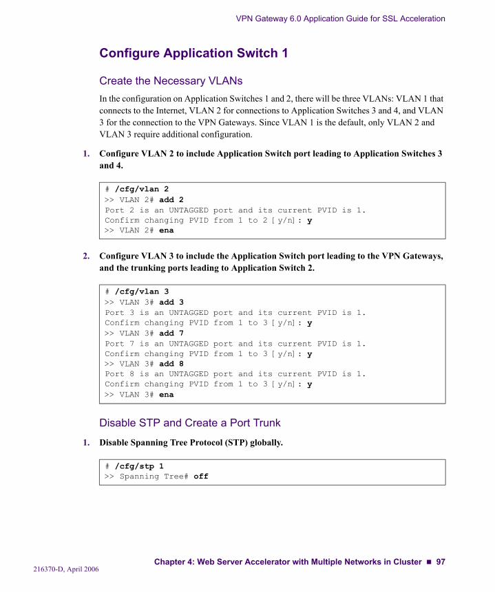
VPN Gateway 6.0 Application Guide for SSL Acceleration
Configure Application Switch 1
Create the Necessary VLANsIn the configuration on Application Switches 1 and 2, there will be three VLANs: VLAN 1 that connects to the Internet, VLAN 2 for connections to Application Switches 3 and 4, and VLAN 3 for the connection to the VPN Gateways. Since VLAN 1 is the default, only VLAN 2 and VLAN 3 require additional configuration.
1. Configure VLAN 2 to include Application Switch port leading to Application Switches 3 and 4.
2. Configure VLAN 3 to include the Application Switch port leading to the VPN Gateways, and the trunking ports leading to Application Switch 2.
Disable STP and Create a Port Trunk
1. Disable Spanning Tree Protocol (STP) globally.
# /cfg/vlan 2>> VLAN 2# add 2Port 2 is an UNTAGGED port and its current PVID is 1.Confirm changing PVID from 1 to 2 [y/n]: y>> VLAN 2# ena
# /cfg/vlan 3>> VLAN 3# add 3Port 3 is an UNTAGGED port and its current PVID is 1.Confirm changing PVID from 1 to 3 [y/n]: y>> VLAN 3# add 7Port 7 is an UNTAGGED port and its current PVID is 1.Confirm changing PVID from 1 to 3 [y/n]: y>> VLAN 3# add 8Port 8 is an UNTAGGED port and its current PVID is 1.Confirm changing PVID from 1 to 3 [y/n]: y>> VLAN 3# ena
# /cfg/stp 1>> Spanning Tree# off
216370-D, April 2006Chapter 4: Web Server Accelerator with Multiple Networks in Cluster 97
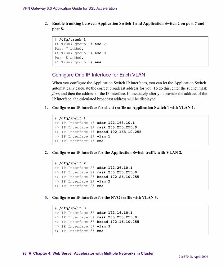
VPN Gateway 6.0 Application Guide for SSL Acceleration
2. Enable trunking between Application Switch 1 and Application Switch 2 on port 7 and port 8.
Configure One IP Interface for Each VLANWhen you configure the Application Switch IP interfaces, you can let the Application Switch automatically calculate the correct broadcast address for you. To do this, enter the subnet mask first, and then the address of the IP interface. Immediately after you provide the address of the IP interface, the calculated broadcast address will be displayed.
1. Configure an IP interface for client traffic on Application Switch 1 with VLAN 1.
2. Configure an IP interface for the Application Switch traffic with VLAN 2.
3. Configure an IP interface for the NVG traffic with VLAN 3.
# /cfg/trunk 1>> Trunk group 1# add 7Port 7 added.>> Trunk group 1# add 8Port 8 added.>> Trunk group 1# ena
# /cfg/ip/if 1>> IP Interface 1# addr 192.168.10.1>> IP Interface 1# mask 255.255.255.0>> IP Interface 1# broad 192.168.10.255>> IP Interface 1# vlan 1>> IP Interface 1# ena
# /cfg/ip/if 2>> IP Interface 2# addr 172.26.10.1>> IP Interface 2# mask 255.255.255.0>> IP Interface 2# broad 172.26.10.255>> IP Interface 2# vlan 2>> IP Interface 2# ena
# /cfg/ip/if 3>> IP Interface 3# addr 172.16.10.1>> IP Interface 3# mask 255.255.255.0>> IP Interface 3# broad 172.16.10.255>> IP Interface 3# vlan 3>> IP Interface 3# ena
216370-D, April 200698 Chapter 4: Web Server Accelerator with Multiple Networks in Cluster
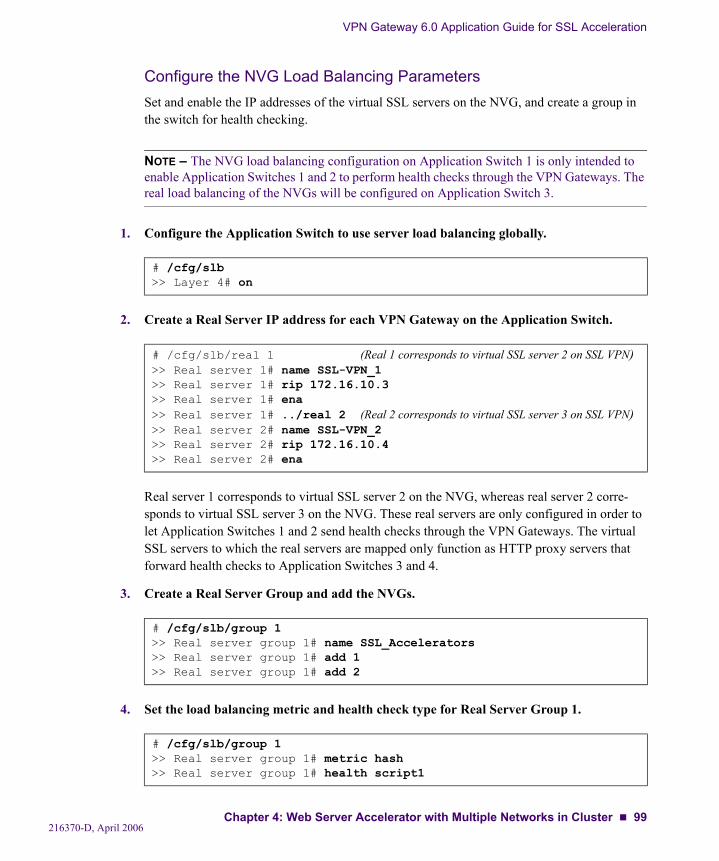
VPN Gateway 6.0 Application Guide for SSL Acceleration
Configure the NVG Load Balancing ParametersSet and enable the IP addresses of the virtual SSL servers on the NVG, and create a group in the switch for health checking.
NOTE – The NVG load balancing configuration on Application Switch 1 is only intended to enable Application Switches 1 and 2 to perform health checks through the VPN Gateways. The real load balancing of the NVGs will be configured on Application Switch 3.
1. Configure the Application Switch to use server load balancing globally.
2. Create a Real Server IP address for each VPN Gateway on the Application Switch.
Real server 1 corresponds to virtual SSL server 2 on the NVG, whereas real server 2 corre-sponds to virtual SSL server 3 on the NVG. These real servers are only configured in order to let Application Switches 1 and 2 send health checks through the VPN Gateways. The virtual SSL servers to which the real servers are mapped only function as HTTP proxy servers that forward health checks to Application Switches 3 and 4.
3. Create a Real Server Group and add the NVGs.
4. Set the load balancing metric and health check type for Real Server Group 1.
# /cfg/slb>> Layer 4# on
# /cfg/slb/real 1 (Real 1 corresponds to virtual SSL server 2 on SSL VPN)>> Real server 1# name SSL-VPN_1>> Real server 1# rip 172.16.10.3>> Real server 1# ena>> Real server 1# ../real 2 (Real 2 corresponds to virtual SSL server 3 on SSL VPN)>> Real server 2# name SSL-VPN_2>> Real server 2# rip 172.16.10.4>> Real server 2# ena
# /cfg/slb/group 1>> Real server group 1# name SSL_Accelerators>> Real server group 1# add 1>> Real server group 1# add 2
# /cfg/slb/group 1>> Real server group 1# metric hash>> Real server group 1# health script1
216370-D, April 2006Chapter 4: Web Server Accelerator with Multiple Networks in Cluster 99
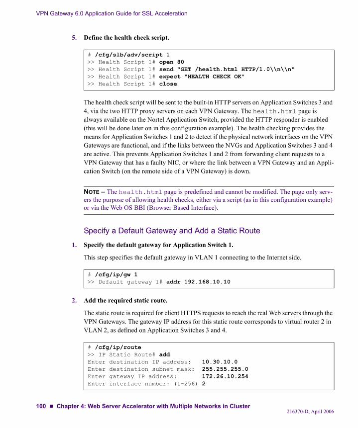
VPN Gateway 6.0 Application Guide for SSL Acceleration
5. Define the health check script.
The health check script will be sent to the built-in HTTP servers on Application Switches 3 and 4, via the two HTTP proxy servers on each VPN Gateway. The health.html page is always available on the Nortel Application Switch, provided the HTTP responder is enabled (this will be done later on in this configuration example). The health checking provides the means for Application Switches 1 and 2 to detect if the physical network interfaces on the VPN Gateways are functional, and if the links between the NVGs and Application Switches 3 and 4 are active. This prevents Application Switches 1 and 2 from forwarding client requests to a VPN Gateway that has a faulty NIC, or where the link between a VPN Gateway and an Appli-cation Switch (on the remote side of a VPN Gateway) is down.
NOTE – The health.html page is predefined and cannot be modified. The page only serv-ers the purpose of allowing health checks, either via a script (as in this configuration example) or via the Web OS BBI (Browser Based Interface).
Specify a Default Gateway and Add a Static Route
1. Specify the default gateway for Application Switch 1.
This step specifies the default gateway in VLAN 1 connecting to the Internet side.
2. Add the required static route.
The static route is required for client HTTPS requests to reach the real Web servers through the VPN Gateways. The gateway IP address for this static route corresponds to virtual router 2 in VLAN 2, as defined on Application Switches 3 and 4.
# /cfg/slb/adv/script 1>> Health Script 1# open 80>> Health Script 1# send "GET /health.html HTTP/1.0\\n\\n">> Health Script 1# expect "HEALTH CHECK OK">> Health Script 1# close
# /cfg/ip/gw 1>> Default gateway 1# addr 192.168.10.10
# /cfg/ip/route>> IP Static Route# addEnter destination IP address: 10.30.10.0Enter destination subnet mask: 255.255.255.0Enter gateway IP address: 172.26.10.254Enter interface number: (1-256) 2
216370-D, April 2006100 Chapter 4: Web Server Accelerator with Multiple Networks in Cluster
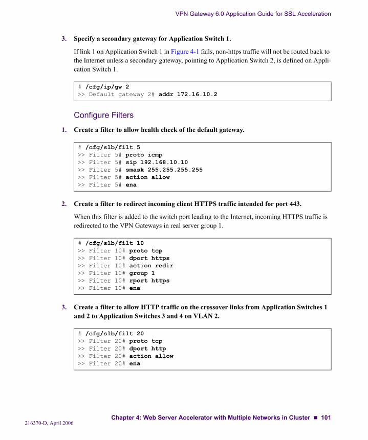
VPN Gateway 6.0 Application Guide for SSL Acceleration
3. Specify a secondary gateway for Application Switch 1.
If link 1 on Application Switch 1 in Figure 4-1 fails, non-https traffic will not be routed back to the Internet unless a secondary gateway, pointing to Application Switch 2, is defined on Appli-cation Switch 1.
Configure Filters
1. Create a filter to allow health check of the default gateway.
2. Create a filter to redirect incoming client HTTPS traffic intended for port 443.
When this filter is added to the switch port leading to the Internet, incoming HTTPS traffic is redirected to the VPN Gateways in real server group 1.
3. Create a filter to allow HTTP traffic on the crossover links from Application Switches 1 and 2 to Application Switches 3 and 4 on VLAN 2.
# /cfg/ip/gw 2>> Default gateway 2# addr 172.16.10.2
# /cfg/slb/filt 5>> Filter 5# proto icmp>> Filter 5# sip 192.168.10.10>> Filter 5# smask 255.255.255.255>> Filter 5# action allow>> Filter 5# ena
# /cfg/slb/filt 10>> Filter 10# proto tcp>> Filter 10# dport https>> Filter 10# action redir>> Filter 10# group 1>> Filter 10# rport https>> Filter 10# ena
# /cfg/slb/filt 20>> Filter 20# proto tcp>> Filter 20# dport http>> Filter 20# action allow>> Filter 20# ena
216370-D, April 2006Chapter 4: Web Server Accelerator with Multiple Networks in Cluster 101
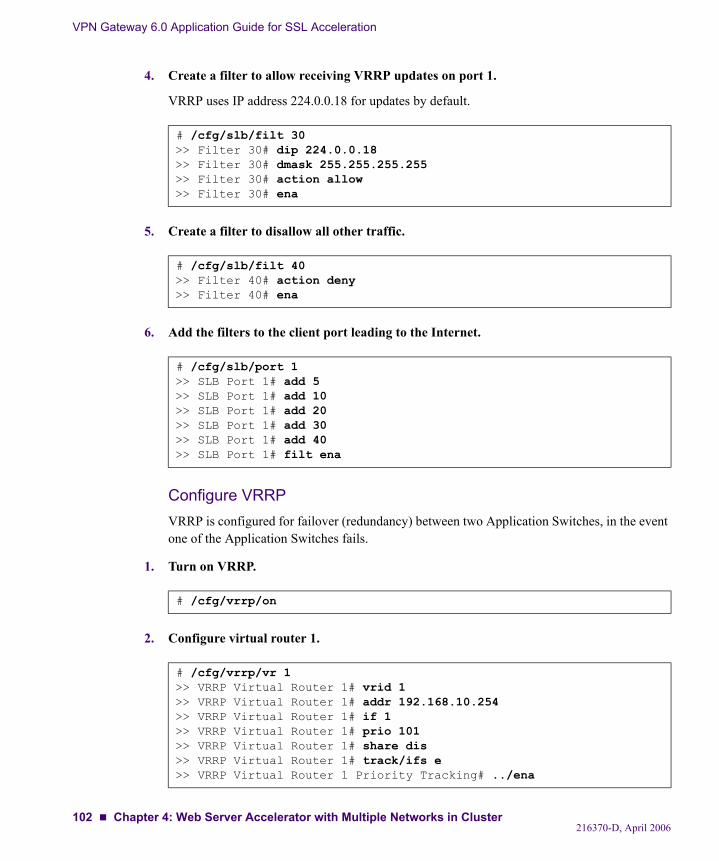
VPN Gateway 6.0 Application Guide for SSL Acceleration
4. Create a filter to allow receiving VRRP updates on port 1.
VRRP uses IP address 224.0.0.18 for updates by default.
5. Create a filter to disallow all other traffic.
6. Add the filters to the client port leading to the Internet.
Configure VRRPVRRP is configured for failover (redundancy) between two Application Switches, in the event one of the Application Switches fails.
1. Turn on VRRP.
2. Configure virtual router 1.
# /cfg/slb/filt 30>> Filter 30# dip 224.0.0.18>> Filter 30# dmask 255.255.255.255>> Filter 30# action allow>> Filter 30# ena
# /cfg/slb/filt 40>> Filter 40# action deny>> Filter 40# ena
# /cfg/slb/port 1>> SLB Port 1# add 5>> SLB Port 1# add 10>> SLB Port 1# add 20>> SLB Port 1# add 30>> SLB Port 1# add 40>> SLB Port 1# filt ena
# /cfg/vrrp/on
# /cfg/vrrp/vr 1>> VRRP Virtual Router 1# vrid 1>> VRRP Virtual Router 1# addr 192.168.10.254>> VRRP Virtual Router 1# if 1>> VRRP Virtual Router 1# prio 101>> VRRP Virtual Router 1# share dis>> VRRP Virtual Router 1# track/ifs e>> VRRP Virtual Router 1 Priority Tracking# ../ena
216370-D, April 2006102 Chapter 4: Web Server Accelerator with Multiple Networks in Cluster
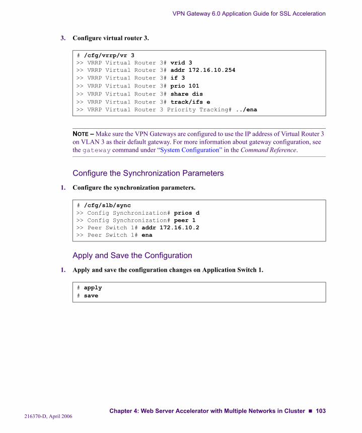
VPN Gateway 6.0 Application Guide for SSL Acceleration
3. Configure virtual router 3.
NOTE – Make sure the VPN Gateways are configured to use the IP address of Virtual Router 3 on VLAN 3 as their default gateway. For more information about gateway configuration, see the gateway command under “System Configuration” in the Command Reference.
Configure the Synchronization Parameters
1. Configure the synchronization parameters.
Apply and Save the Configuration
1. Apply and save the configuration changes on Application Switch 1.
# /cfg/vrrp/vr 3>> VRRP Virtual Router 3# vrid 3>> VRRP Virtual Router 3# addr 172.16.10.254>> VRRP Virtual Router 3# if 3>> VRRP Virtual Router 3# prio 101>> VRRP Virtual Router 3# share dis>> VRRP Virtual Router 3# track/ifs e>> VRRP Virtual Router 3 Priority Tracking# ../ena
# /cfg/slb/sync>> Config Synchronization# prios d>> Config Synchronization# peer 1>> Peer Switch 1# addr 172.16.10.2>> Peer Switch 1# ena
# apply# save
216370-D, April 2006Chapter 4: Web Server Accelerator with Multiple Networks in Cluster 103
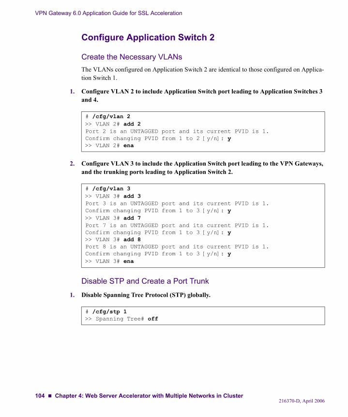
VPN Gateway 6.0 Application Guide for SSL Acceleration
Configure Application Switch 2
Create the Necessary VLANsThe VLANs configured on Application Switch 2 are identical to those configured on Applica-tion Switch 1.
1. Configure VLAN 2 to include Application Switch port leading to Application Switches 3 and 4.
2. Configure VLAN 3 to include the Application Switch port leading to the VPN Gateways, and the trunking ports leading to Application Switch 2.
Disable STP and Create a Port Trunk
1. Disable Spanning Tree Protocol (STP) globally.
# /cfg/vlan 2>> VLAN 2# add 2Port 2 is an UNTAGGED port and its current PVID is 1.Confirm changing PVID from 1 to 2 [y/n]: y>> VLAN 2# ena
# /cfg/vlan 3>> VLAN 3# add 3Port 3 is an UNTAGGED port and its current PVID is 1.Confirm changing PVID from 1 to 3 [y/n]: y>> VLAN 3# add 7Port 7 is an UNTAGGED port and its current PVID is 1.Confirm changing PVID from 1 to 3 [y/n]: y>> VLAN 3# add 8Port 8 is an UNTAGGED port and its current PVID is 1.Confirm changing PVID from 1 to 3 [y/n]: y>> VLAN 3# ena
# /cfg/stp 1>> Spanning Tree# off
216370-D, April 2006104 Chapter 4: Web Server Accelerator with Multiple Networks in Cluster
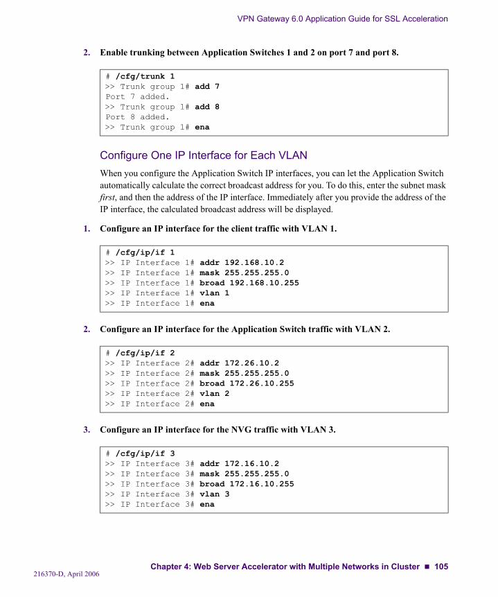
VPN Gateway 6.0 Application Guide for SSL Acceleration
2. Enable trunking between Application Switches 1 and 2 on port 7 and port 8.
Configure One IP Interface for Each VLANWhen you configure the Application Switch IP interfaces, you can let the Application Switch automatically calculate the correct broadcast address for you. To do this, enter the subnet mask first, and then the address of the IP interface. Immediately after you provide the address of the IP interface, the calculated broadcast address will be displayed.
1. Configure an IP interface for the client traffic with VLAN 1.
2. Configure an IP interface for the Application Switch traffic with VLAN 2.
3. Configure an IP interface for the NVG traffic with VLAN 3.
# /cfg/trunk 1>> Trunk group 1# add 7Port 7 added.>> Trunk group 1# add 8Port 8 added.>> Trunk group 1# ena
# /cfg/ip/if 1>> IP Interface 1# addr 192.168.10.2>> IP Interface 1# mask 255.255.255.0>> IP Interface 1# broad 192.168.10.255>> IP Interface 1# vlan 1>> IP Interface 1# ena
# /cfg/ip/if 2>> IP Interface 2# addr 172.26.10.2>> IP Interface 2# mask 255.255.255.0>> IP Interface 2# broad 172.26.10.255>> IP Interface 2# vlan 2>> IP Interface 2# ena
# /cfg/ip/if 3>> IP Interface 3# addr 172.16.10.2>> IP Interface 3# mask 255.255.255.0>> IP Interface 3# broad 172.16.10.255>> IP Interface 3# vlan 3>> IP Interface 3# ena
216370-D, April 2006Chapter 4: Web Server Accelerator with Multiple Networks in Cluster 105
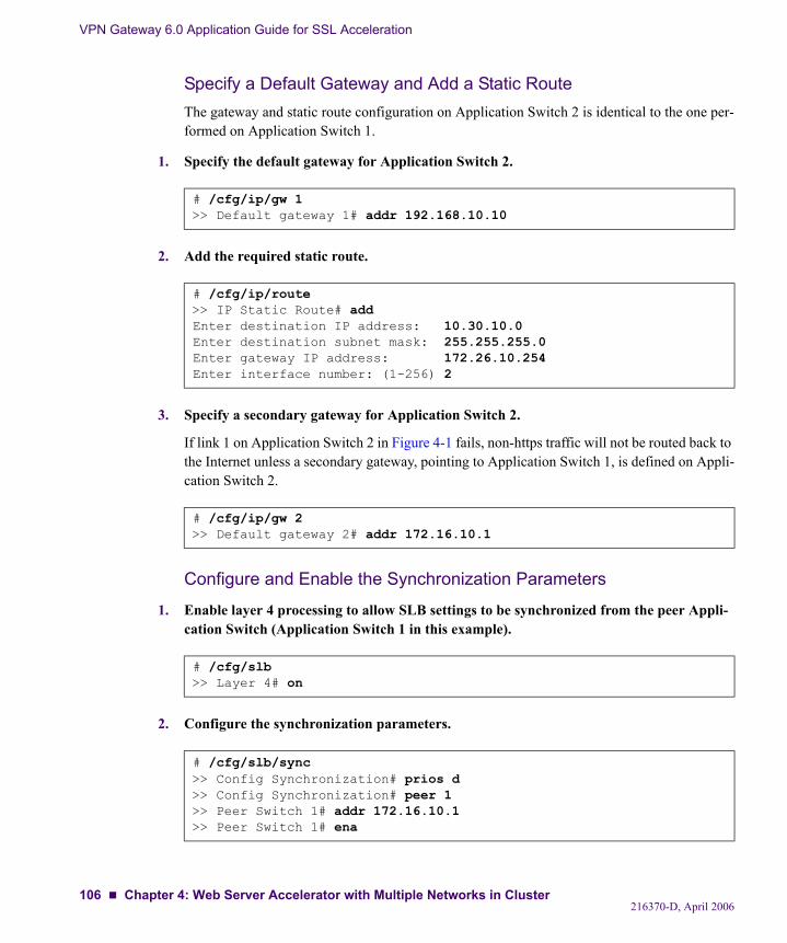
VPN Gateway 6.0 Application Guide for SSL Acceleration
Specify a Default Gateway and Add a Static RouteThe gateway and static route configuration on Application Switch 2 is identical to the one per-formed on Application Switch 1.
1. Specify the default gateway for Application Switch 2.
2. Add the required static route.
3. Specify a secondary gateway for Application Switch 2.
If link 1 on Application Switch 2 in Figure 4-1 fails, non-https traffic will not be routed back to the Internet unless a secondary gateway, pointing to Application Switch 1, is defined on Appli-cation Switch 2.
Configure and Enable the Synchronization Parameters
1. Enable layer 4 processing to allow SLB settings to be synchronized from the peer Appli-cation Switch (Application Switch 1 in this example).
2. Configure the synchronization parameters.
# /cfg/ip/gw 1>> Default gateway 1# addr 192.168.10.10
# /cfg/ip/route>> IP Static Route# addEnter destination IP address: 10.30.10.0Enter destination subnet mask: 255.255.255.0Enter gateway IP address: 172.26.10.254Enter interface number: (1-256) 2
# /cfg/ip/gw 2>> Default gateway 2# addr 172.16.10.1
# /cfg/slb>> Layer 4# on
# /cfg/slb/sync>> Config Synchronization# prios d>> Config Synchronization# peer 1>> Peer Switch 1# addr 172.16.10.1>> Peer Switch 1# ena
216370-D, April 2006106 Chapter 4: Web Server Accelerator with Multiple Networks in Cluster
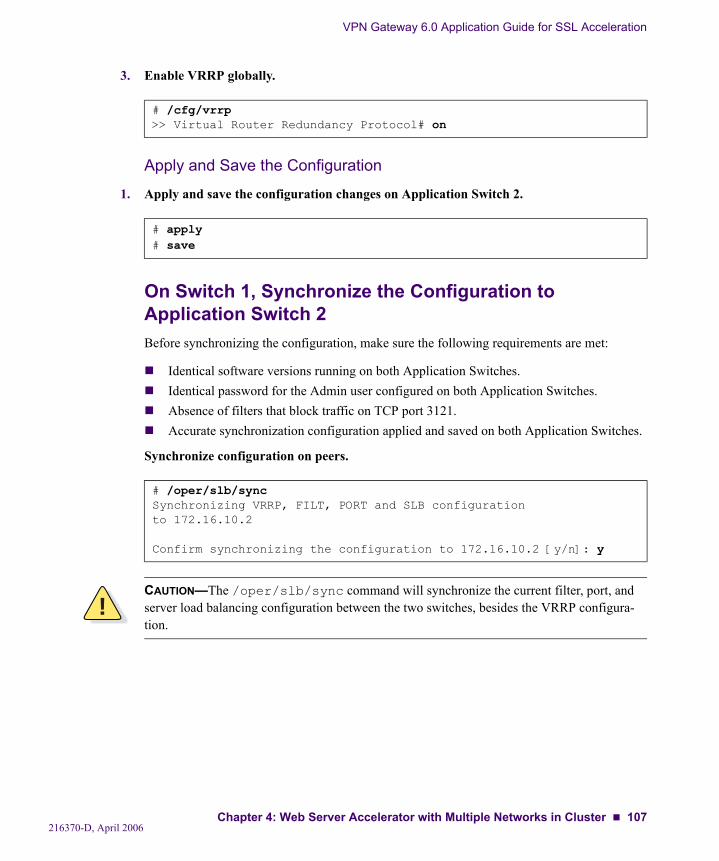
VPN Gateway 6.0 Application Guide for SSL Acceleration
3. Enable VRRP globally.
Apply and Save the Configuration
1. Apply and save the configuration changes on Application Switch 2.
On Switch 1, Synchronize the Configuration to Application Switch 2Before synchronizing the configuration, make sure the following requirements are met:
Identical software versions running on both Application Switches.Identical password for the Admin user configured on both Application Switches.Absence of filters that block traffic on TCP port 3121.Accurate synchronization configuration applied and saved on both Application Switches.
Synchronize configuration on peers.
# /cfg/vrrp>> Virtual Router Redundancy Protocol# on
# apply# save
# /oper/slb/syncSynchronizing VRRP, FILT, PORT and SLB configurationto 172.16.10.2
Confirm synchronizing the configuration to 172.16.10.2 [y/n]: y
!CAUTION—The /oper/slb/sync command will synchronize the current filter, port, and server load balancing configuration between the two switches, besides the VRRP configura-tion.
216370-D, April 2006Chapter 4: Web Server Accelerator with Multiple Networks in Cluster 107
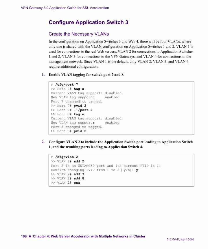
VPN Gateway 6.0 Application Guide for SSL Acceleration
Configure Application Switch 3
Create the Necessary VLANsIn the configuration on Application Switches 3 and Web 4, there will be four VLANs, where only one is shared with the VLAN configuration on Application Switches 1 and 2. VLAN 1 is used for connections to the real Web servers, VLAN 2 for connections to Application Switches 1 and 2, VLAN 3 for connections to the VPN Gateways, and VLAN 4 for connections to the management network. Since VLAN 1 is the default, only VLAN 2, VLAN 3, and VLAN 4 require additional configuration.
1. Enable VLAN tagging for switch port 7 and 8.
2. Configure VLAN 2 to include the Application Switch port leading to Application Switch 1, and the trunking ports leading to Application Switch 4.
# /cfg/port 7>> Port 7# tag eCurrent VLAN tag support: disabledNew VLAN tag support: enabledPort 7 changed to tagged.>> Port 7# pvid 2>> Port 7# ../port 8>> Port 8# tag eCurrent VLAN tag support: disabledNew VLAN tag support: enabledPort 8 changed to tagged.>> Port 8# pvid 2
# /cfg/vlan 2>> VLAN 2# add 2Port 2 is an UNTAGGED port and its current PVID is 1.Confirm changing PVID from 1 to 2 [y/n]: y>> VLAN 2# add 7>> VLAN 2# add 8>> VLAN 2# ena
216370-D, April 2006108 Chapter 4: Web Server Accelerator with Multiple Networks in Cluster
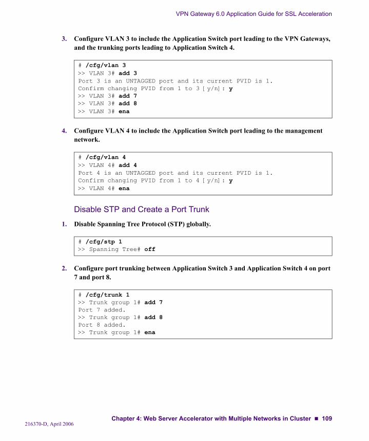
VPN Gateway 6.0 Application Guide for SSL Acceleration
3. Configure VLAN 3 to include the Application Switch port leading to the VPN Gateways, and the trunking ports leading to Application Switch 4.
4. Configure VLAN 4 to include the Application Switch port leading to the management network.
Disable STP and Create a Port Trunk
1. Disable Spanning Tree Protocol (STP) globally.
2. Configure port trunking between Application Switch 3 and Application Switch 4 on port 7 and port 8.
# /cfg/vlan 3>> VLAN 3# add 3Port 3 is an UNTAGGED port and its current PVID is 1.Confirm changing PVID from 1 to 3 [y/n]: y>> VLAN 3# add 7>> VLAN 3# add 8>> VLAN 3# ena
# /cfg/vlan 4>> VLAN 4# add 4Port 4 is an UNTAGGED port and its current PVID is 1.Confirm changing PVID from 1 to 4 [y/n]: y>> VLAN 4# ena
# /cfg/stp 1>> Spanning Tree# off
# /cfg/trunk 1>> Trunk group 1# add 7Port 7 added.>> Trunk group 1# add 8Port 8 added.>> Trunk group 1# ena
216370-D, April 2006Chapter 4: Web Server Accelerator with Multiple Networks in Cluster 109
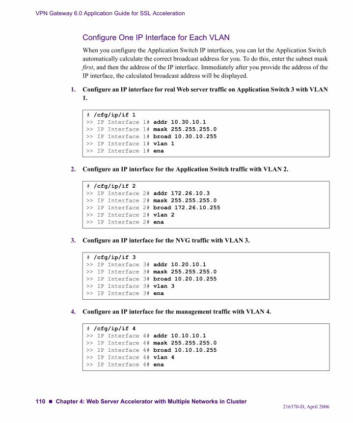
VPN Gateway 6.0 Application Guide for SSL Acceleration
Configure One IP Interface for Each VLANWhen you configure the Application Switch IP interfaces, you can let the Application Switch automatically calculate the correct broadcast address for you. To do this, enter the subnet mask first, and then the address of the IP interface. Immediately after you provide the address of the IP interface, the calculated broadcast address will be displayed.
1. Configure an IP interface for real Web server traffic on Application Switch 3 with VLAN 1.
2. Configure an IP interface for the Application Switch traffic with VLAN 2.
3. Configure an IP interface for the NVG traffic with VLAN 3.
4. Configure an IP interface for the management traffic with VLAN 4.
# /cfg/ip/if 1>> IP Interface 1# addr 10.30.10.1>> IP Interface 1# mask 255.255.255.0>> IP Interface 1# broad 10.30.10.255>> IP Interface 1# vlan 1>> IP Interface 1# ena
# /cfg/ip/if 2>> IP Interface 2# addr 172.26.10.3>> IP Interface 2# mask 255.255.255.0>> IP Interface 2# broad 172.26.10.255>> IP Interface 2# vlan 2>> IP Interface 2# ena
# /cfg/ip/if 3>> IP Interface 3# addr 10.20.10.1>> IP Interface 3# mask 255.255.255.0>> IP Interface 3# broad 10.20.10.255>> IP Interface 3# vlan 3>> IP Interface 3# ena
# /cfg/ip/if 4>> IP Interface 4# addr 10.10.10.1>> IP Interface 4# mask 255.255.255.0>> IP Interface 4# broad 10.10.10.255>> IP Interface 4# vlan 4>> IP Interface 4# ena
216370-D, April 2006110 Chapter 4: Web Server Accelerator with Multiple Networks in Cluster
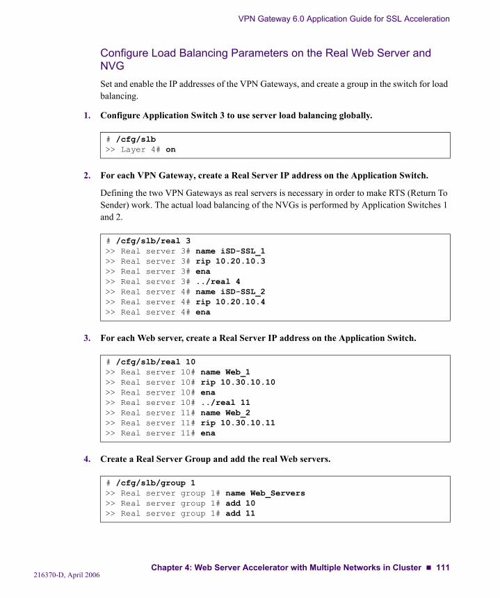
VPN Gateway 6.0 Application Guide for SSL Acceleration
Configure Load Balancing Parameters on the Real Web Server and NVG Set and enable the IP addresses of the VPN Gateways, and create a group in the switch for load balancing.
1. Configure Application Switch 3 to use server load balancing globally.
2. For each VPN Gateway, create a Real Server IP address on the Application Switch.
Defining the two VPN Gateways as real servers is necessary in order to make RTS (Return To Sender) work. The actual load balancing of the NVGs is performed by Application Switches 1 and 2.
3. For each Web server, create a Real Server IP address on the Application Switch.
4. Create a Real Server Group and add the real Web servers.
# /cfg/slb>> Layer 4# on
# /cfg/slb/real 3>> Real server 3# name iSD-SSL_1>> Real server 3# rip 10.20.10.3>> Real server 3# ena>> Real server 3# ../real 4>> Real server 4# name iSD-SSL_2>> Real server 4# rip 10.20.10.4>> Real server 4# ena
# /cfg/slb/real 10>> Real server 10# name Web_1>> Real server 10# rip 10.30.10.10>> Real server 10# ena>> Real server 10# ../real 11>> Real server 11# name Web_2>> Real server 11# rip 10.30.10.11>> Real server 11# ena
# /cfg/slb/group 1>> Real server group 1# name Web_Servers>> Real server group 1# add 10>> Real server group 1# add 11
216370-D, April 2006Chapter 4: Web Server Accelerator with Multiple Networks in Cluster 111
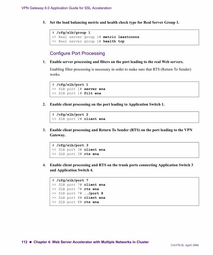
VPN Gateway 6.0 Application Guide for SSL Acceleration
5. Set the load balancing metric and health check type for Real Server Group 1.
Configure Port Processing
1. Enable server processing and filters on the port leading to the real Web servers.
Enabling filter processing is necessary in order to make sure that RTS (Return To Sender) works.
2. Enable client processing on the port leading to Application Switch 1.
3. Enable client processing and Return To Sender (RTS) on the port leading to the VPN Gateway.
4. Enable client processing and RTS on the trunk ports connecting Application Switch 3 and Application Switch 4.
# /cfg/slb/group 1>> Real server group 1# metric leastconns>> Real server group 1# health tcp
# /cfg/slb/port 1>> SLB port 1# server ena>> SLB port 1# filt ena
# /cfg/slb/port 2>> SLB port 2# client ena
# /cfg/slb/port 3>> SLB port 3# client ena>> SLB port 3# rts ena
# /cfg/slb/port 7>> SLB port 7# client ena>> SLB port 7# rts ena>> SLB port 7# ../port 8>> SLB port 8# client ena>> SLB port 8# rts ena
216370-D, April 2006112 Chapter 4: Web Server Accelerator with Multiple Networks in Cluster
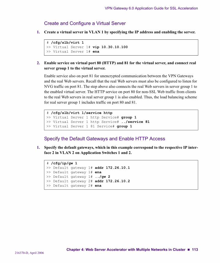
VPN Gateway 6.0 Application Guide for SSL Acceleration
Create and Configure a Virtual Server
1. Create a virtual server in VLAN 1 by specifying the IP address and enabling the server.
2. Enable service on virtual port 80 (HTTP) and 81 for the virtual server, and connect real server group 1 to the virtual server.
Enable service also on port 81 for unencrypted communication between the VPN Gateways and the real Web servers. Recall that the real Web servers must also be configured to listen for NVG traffic on port 81. The step above also connects the real Web servers in server group 1 to the enabled virtual server. The HTTP service on port 80 for non-SSL Web traffic from clients to the real Web servers in real server group 1 is also enabled. Thus, the load balancing scheme for real server group 1 includes traffic on port 80 and 81.
Specify the Default Gateways and Enable HTTP Access
1. Specify the default gateways, which in this example correspond to the respective IP inter-face 2 in VLAN 2 on Application Switches 1 and 2.
# /cfg/slb/virt 1>> Virtual Server 1# vip 10.30.10.100>> Virtual Server 1# ena
# /cfg/slb/virt 1/service http>> Virtual Server 1 http Service# group 1>> Virtual Server 1 http Service# ../service 81>> Virtual Server 1 81 Service# group 1
# /cfg/ip/gw 1>> Default gateway 1# addr 172.26.10.1>> Default gateway 1# ena>> Default gateway 1# ../gw 2>> Default gateway 2# addr 172.26.10.2>> Default gateway 2# ena
216370-D, April 2006Chapter 4: Web Server Accelerator with Multiple Networks in Cluster 113

VPN Gateway 6.0 Application Guide for SSL Acceleration
2. Enable the HTTP responder in order to respond to the health checking performed by Application Switch 1.
NOTE – When enabling the HTTP responder you may also enable the Web browser based switch management interface (Web OS BBI), depending on the Web OS version and the Nortel Application Switch model. You should therefore make sure that you are not using the default password for the Administrator user on the Application Switch. If you change the password on Application Switch 3, make sure that you configure Application Switch 4 to use the same pass-word or the configuration synchronization between the two Application Switches will fail.
Configure VRRPVRRP is configured for failover (redundancy) between Application Switches 3 and 4, in the event one of the Application Switches fails. In this configuration, Application Switch 3 will be the master (achieved by setting prio to 101).
1. Globally turn on the VRRP.
2. Configure and enable virtual router 1 for IP interface 1 on VLAN 1.
# /cfg/sys>> System# http ena
# /cfg/vrrp/on
# /cfg/vrrp/vr 1>> VRRP Virtual Router 1# vrid 1>> VRRP Virtual Router 1# addr 10.30.10.254>> VRRP Virtual Router 1# if 1>> VRRP Virtual Router 1# prio 101>> VRRP Virtual Router 1# share dis>> VRRP Virtual Router 1# track/ifs e>> VRRP Virtual Router 1 Priority Tracking# ../ena
216370-D, April 2006114 Chapter 4: Web Server Accelerator with Multiple Networks in Cluster
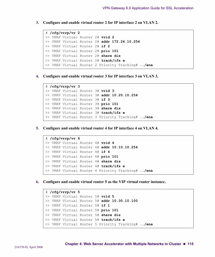
VPN Gateway 6.0 Application Guide for SSL Acceleration
3. Configure and enable virtual router 2 for IP interface 2 on VLAN 2.
4. Configure and enable virtual router 3 for IP interface 3 on VLAN 3.
5. Configure and enable virtual router 4 for IP interface 4 on VLAN 4.
6. Configure and enable virtual router 5 as the VIP virtual router instance.
# /cfg/vrrp/vr 2>> VRRP Virtual Router 2# vrid 2>> VRRP Virtual Router 2# addr 172.26.10.254>> VRRP Virtual Router 2# if 2>> VRRP Virtual Router 2# prio 101>> VRRP Virtual Router 2# share dis>> VRRP Virtual Router 2# track/ifs e>> VRRP Virtual Router 2 Priority Tracking# ../ena
# /cfg/vrrp/vr 3>> VRRP Virtual Router 3# vrid 3>> VRRP Virtual Router 3# addr 10.20.10.254>> VRRP Virtual Router 3# if 3>> VRRP Virtual Router 3# prio 101>> VRRP Virtual Router 3# share dis>> VRRP Virtual Router 3# track/ifs e>> VRRP Virtual Router 3 Priority Tracking# ../ena
# /cfg/vrrp/vr 4>> VRRP Virtual Router 4# vrid 4>> VRRP Virtual Router 4# addr 10.10.10.254>> VRRP Virtual Router 4# if 4>> VRRP Virtual Router 4# prio 101>> VRRP Virtual Router 4# share dis>> VRRP Virtual Router 4# track/ifs e>> VRRP Virtual Router 4 Priority Tracking# ../ena
# /cfg/vrrp/vr 5>> VRRP Virtual Router 5# vrid 5>> VRRP Virtual Router 5# addr 10.30.10.100>> VRRP Virtual Router 5# if 1>> VRRP Virtual Router 5# prio 101>> VRRP Virtual Router 5# share dis>> VRRP Virtual Router 5# track/ifs e>> VRRP Virtual Router 5 Priority Tracking# ../ena
216370-D, April 2006Chapter 4: Web Server Accelerator with Multiple Networks in Cluster 115

VPN Gateway 6.0 Application Guide for SSL Acceleration
Configure the Synchronization Parameters
1. Configure the synchronization parameters.
Apply and Save the Configuration
1. Apply and save the configuration changes on Application Switch 3.
# /cfg/slb/sync>> Config Synchronization# prios d>> Config Synchronization# peer 1>> Peer Switch 1# addr 172.26.10.4>> Peer Switch 1# ena
# apply# save
216370-D, April 2006116 Chapter 4: Web Server Accelerator with Multiple Networks in Cluster
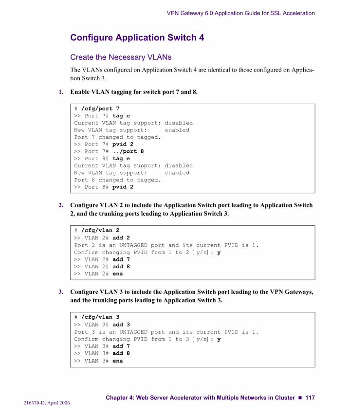
VPN Gateway 6.0 Application Guide for SSL Acceleration
Configure Application Switch 4
Create the Necessary VLANsThe VLANs configured on Application Switch 4 are identical to those configured on Applica-tion Switch 3.
1. Enable VLAN tagging for switch port 7 and 8.
2. Configure VLAN 2 to include the Application Switch port leading to Application Switch 2, and the trunking ports leading to Application Switch 3.
3. Configure VLAN 3 to include the Application Switch port leading to the VPN Gateways, and the trunking ports leading to Application Switch 3.
# /cfg/port 7>> Port 7# tag eCurrent VLAN tag support: disabledNew VLAN tag support: enabledPort 7 changed to tagged.>> Port 7# pvid 2>> Port 7# ../port 8>> Port 8# tag eCurrent VLAN tag support: disabledNew VLAN tag support: enabledPort 8 changed to tagged.>> Port 8# pvid 2
# /cfg/vlan 2>> VLAN 2# add 2Port 2 is an UNTAGGED port and its current PVID is 1.Confirm changing PVID from 1 to 2 [y/n]: y>> VLAN 2# add 7>> VLAN 2# add 8>> VLAN 2# ena
# /cfg/vlan 3>> VLAN 3# add 3Port 3 is an UNTAGGED port and its current PVID is 1.Confirm changing PVID from 1 to 3 [y/n]: y>> VLAN 3# add 7>> VLAN 3# add 8>> VLAN 3# ena
216370-D, April 2006Chapter 4: Web Server Accelerator with Multiple Networks in Cluster 117
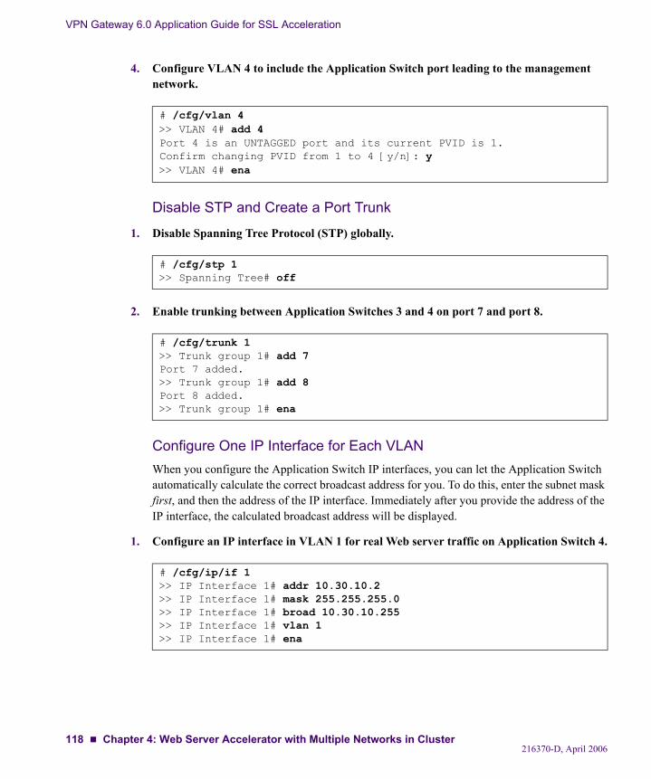
VPN Gateway 6.0 Application Guide for SSL Acceleration
4. Configure VLAN 4 to include the Application Switch port leading to the management network.
Disable STP and Create a Port Trunk
1. Disable Spanning Tree Protocol (STP) globally.
2. Enable trunking between Application Switches 3 and 4 on port 7 and port 8.
Configure One IP Interface for Each VLANWhen you configure the Application Switch IP interfaces, you can let the Application Switch automatically calculate the correct broadcast address for you. To do this, enter the subnet mask first, and then the address of the IP interface. Immediately after you provide the address of the IP interface, the calculated broadcast address will be displayed.
1. Configure an IP interface in VLAN 1 for real Web server traffic on Application Switch 4.
# /cfg/vlan 4>> VLAN 4# add 4Port 4 is an UNTAGGED port and its current PVID is 1.Confirm changing PVID from 1 to 4 [y/n]: y>> VLAN 4# ena
# /cfg/stp 1>> Spanning Tree# off
# /cfg/trunk 1>> Trunk group 1# add 7Port 7 added.>> Trunk group 1# add 8Port 8 added.>> Trunk group 1# ena
# /cfg/ip/if 1>> IP Interface 1# addr 10.30.10.2>> IP Interface 1# mask 255.255.255.0>> IP Interface 1# broad 10.30.10.255>> IP Interface 1# vlan 1>> IP Interface 1# ena
216370-D, April 2006118 Chapter 4: Web Server Accelerator with Multiple Networks in Cluster
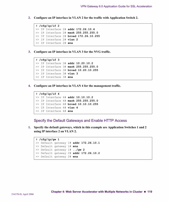
VPN Gateway 6.0 Application Guide for SSL Acceleration
2. Configure an IP interface in VLAN 2 for the traffic with Application Switch 2.
3. Configure an IP interface in VLAN 3 for the NVG traffic.
4. Configure an IP interface in VLAN 4 for the management traffic.
Specify the Default Gateways and Enable HTTP Access
1. Specify the default gateways, which in this example are Application Switches 1 and 2 using IP interface 2 on VLAN 2.
# /cfg/ip/if 2>> IP Interface 2# addr 172.26.10.4>> IP Interface 2# mask 255.255.255.0>> IP Interface 2# broad 172.26.10.255>> IP Interface 2# vlan 2>> IP Interface 2# ena
# /cfg/ip/if 3>> IP Interface 3# addr 10.20.10.2>> IP Interface 3# mask 255.255.255.0>> IP Interface 3# broad 10.20.10.255>> IP Interface 3# vlan 3>> IP Interface 3# ena
# /cfg/ip/if 4>> IP Interface 4# addr 10.10.10.2>> IP Interface 4# mask 255.255.255.0>> IP Interface 4# broad 10.10.10.255>> IP Interface 4# vlan 4>> IP Interface 4# ena
# /cfg/ip/gw 1>> Default gateway 1# addr 172.26.10.1>> Default gateway 1# ena>> Default gateway 1# ../gw 2>> Default gateway 2# addr 172.26.10.2>> Default gateway 2# ena
216370-D, April 2006Chapter 4: Web Server Accelerator with Multiple Networks in Cluster 119
VPN Gateway 6.0 Application Guide for SSL Acceleration
2. Enable the HTTP responder in order to respond to the health checking performed by Application Switch 2.
NOTE – When enabling the HTTP responder you may also enable the Web browser based switch management interface (Web OS BBI), depending on the Web OS version and the Nortel Application Switch model. You should therefore make sure that you are not using the default password for the Administrator user on the Application Switch. If you change the password, make sure that you specify the same password as on Application Switch 3 or the configuration synchronization between the two Application Switches will fail.
Configure the Synchronization Parameters
1. Enable layer 4 processing to allow SLB settings to be synchronized from the peer Appli-cation Switch (Application Switch 3 in this example).
2. Configure the synchronization parameters.
3. Enable VRRP globally.
Apply and Save the Configuration
1. Apply and save the configuration changes on Application Switch 4.
# /cfg/sys>> System# http ena
# /cfg/slb>> Layer 4# on
# /cfg/slb/sync>> Config Synchronization# prios d>> Config Synchronization# peer 1>> Peer Switch 1# addr 172.26.10.3>> Peer Switch 1# ena
# /cfg/vrrp>> Virtual Router Redundancy Protocol# on
# apply# save
216370-D, April 2006120 Chapter 4: Web Server Accelerator with Multiple Networks in Cluster

VPN Gateway 6.0 Application Guide for SSL Acceleration
On Switch 3, Synchronize the Configuration to Application Switch 4Before synchronizing the configuration, make sure the following requirements are met:
Identical software versions running on both Application Switches.Identical password for the Admin user configured on both Application Switches.Absence of filters that block traffic on TCP port 3121.
Accurate synchronization configuration applied and saved on both Application Switches.
Synchronize configuration on peers.
# /oper/slb/syncSynchronizing VRRP, FILT, PORT and SLB configurationto 172.26.10.4
Confirm synchronizing the configuration to 172.26.10.4 [y/n]: y
!CAUTION—The /oper/slb/sync command will synchronize the current filter, port, and server load balancing configuration between the two switches, besides the VRRP configura-tion.
216370-D, April 2006Chapter 4: Web Server Accelerator with Multiple Networks in Cluster 121

VPN Gateway 6.0 Application Guide for SSL Acceleration
216370-D, April 2006122 Chapter 4: Web Server Accelerator with Multiple Networks in Cluster
CHAPTER 5Configuring the NVG to Rewrite Client Requests
If the client’s Web browser is not capable of meeting the cipher list requirement you have spec-ified for a virtual SSL server on the Nortel VPN Gateway (NVG), you can enable the rewrite functionality in order to let the Web server display a customized error message. Without this functionality, the SSL session between the client and the VPN Gateway would simply be ter-minated during the SSL handshake.
Setting up Rewrite of Weak Cipher Client RequestsThis example assumes that you already have configured a virtual SSL server for the HTTPS service, as described in the Web Server Accelerator example on page 24.
Log in as the administrator to the NVG cluster by using a Telnet or SSH connection to the Management IP address (MIP). The configuration changes will automatically be propagated to all VPN Gateways in the cluster.
1. Decide which virtual SSL server to configure.
View the displayed information about certificates and virtual SSL servers. If you have config-ured more than one virtual SSL server, identify the server used for HTTPS by verifying that the Listen port value is set to 443 (HTTPS). In this example virtual SSL server 1 is used as an example for the configuration changes.
>> Main# cfg/ssl>> SSL# cur
216370-D, April 2006123
VPN Gateway 6.0 Application Guide for SSL Acceleration
2. Examine the current settings for the chosen virtual SSL server.
Examine the settings and make sure that the virtual SSL server is enabled. Take special notice of the SSL settings and the current cipher list, which denotes the cipher strength. If you have not modified the cipher list, it should correspond to the default value of ALL@STRENGTH.
3. Set the SSL server type to HTTP.
In order to make use of high-level HTTP capabilities, such as rewriting client requests, the vir-tual SSL server type needs to be changed to http. Also, without changing the type to http, the HTTP Settings menu and Rewrite menu are not even activated.
>> SSL# serverEnter virtual server number: (1-) 1 (example)>> Server 1# cur
Server 1: Server name = test_server IP addr(s) of server = 192.168.10.100 Standalone mode = off Listen port of server = 443 (https) Real server IP addr = 0.0.0.0 Real server port = 81 Type (generic/http/socks) = generic Transparent proxy mode (on/off) = on Enable virtual server = enabled
SSL Settings: Server certificate = 1 SSL cache size = 4000 SSL cache timeout = 5m List of accepted signers of client certificates = List of CA chain certificates = Protocol version = ssl3 Certificate verification level = none Cipher list = ALL@STRENGTH Enable SSL = enabled
TCP Settings: (continued on-screen)
>> Server 1# typeCurrent value: genericType (generic/http/socks): http
216370-D, April 2006124 Chapter 5: Configuring the NVG to Rewrite Client Requests
VPN Gateway 6.0 Application Guide for SSL Acceleration
4. Access the HTTP menu and the Rewrite menu, then enable the rewrite functionality.
5. Specify which cipher list to accept.
Specify the rewrite cipher list (in uppercase letters) that you actually require here, or accept the default rewrite cipher list (HIGH:MEDIUM). The cipher strength that you actually require must always be higher than the cipher strength provided by the cipher list specified under the SSL Settings menu (you viewed these settings in step 2). This way, clients using a Web browser that does not meet the actual cipher strength requirements can still establish an SSL session and get a customized error message from the Web server (or a default error message from the NVG), even if the actual requirements are not met.
The rewrite function is only triggered when a client browser can perform the lower cipher strength specified under the SSL Settings menu, but is unable to perform the higher cipher strength you specify in this step. When both cipher requirements are met, the SSL session is established transparently without the involvement of the rewrite function.
Again, verify that the cipher list you specify in this step provides higher cipher strength than the cipher list you took note of in step 2. For more information about ciphers, see the “Sup-ported Ciphers” appendix in the User’s Guide. If you find that you need to change the cipher list specified under the SSL Settings menu, use the command /cfg/ssl/server, specify the desired virtual SSL server, and then type the command ssl/ciphers.
>> Server 1# http>> HTTP Settings# rewrite>> Rewrite# rewriteCurrent value: offEnable rewrite (on/off): onYou may need to adjust the server #/ssl/cipher setting.For step-up certificates we recommend ALL:-RC2:-SHA1:@STRENGTH
>> Rewrite Menu for Server 1# ciphersCurrent value: HIGH:MEDIUMEnter cipher list: RC4:ALL:!EXPORT:!DH
216370-D, April 2006Chapter 5: Configuring the NVG to Rewrite Client Requests 125
VPN Gateway 6.0 Application Guide for SSL Acceleration
6. Configure the SSL server to let the Web server handle the client response.
In this example, configure the SSL server to let the Web server handle the response sent back to the client browser when the rewrite function is triggered. This configuration also requires specifying a valid URI, pointing to a resource on the Web server (described in the next step).
If you choose to let the NVG (iSD) handle the response, it returns a predefined error message to the client browser if the required cipher strength is not met. An example of such a pre-defined error message emanating from the NVG can be:
7. Specify the URI to add when rewriting the client request.
Specify a URI pointing to a resource on the Web server to which the client made its initial request. The URI can point to a static HTML page, or to a server-side script generating a dynamic error message. A dynamic error message can be based on the session specific infor-mation that the rewrite function automatically adds to the modified request that is passed on to the Web server.
If you specify MEDIUM as the cipher list (used only as an example) and /cipheralert.asp for the URI, the rewritten client request sent on to the Web server would look similar to this:
“GET /cipheralert.asp?c=TLSv1/SSLv3:RC4-MD5&cs=MEDIUM HTTP/1.0”Where c stands for client, and cs stands for (required) cipher suite.
8. Apply your settings.
>> Rewrite# responseCurrent value: iSDEnter the source of response (iSD/WebServer): WebServer
www.example.com requires stronger cryptography support of your browser.
Your browser used TLSv1/SSLv3, with the cipher suite RC4-MD5,which is not one of the accepted ones: NULL-SHA
>> Rewrite# URICurrent value: /cgi-bin/weakcipherEnter the URI address (WebServer response only): /cipheralert.asp
>> Rewrite# applyChanges applied successfully.
216370-D, April 2006126 Chapter 5: Configuring the NVG to Rewrite Client Requests
CHAPTER 6HTTP to HTTPS Redirection
This chapter describes how to configure the Nortel VPN Gateway (NVG) to automatically transform an HTTP client request into the required HTTPS request. By configuring such a redirect service on the NVG, the user can simply enter the fully qualified domain name in the web browser’s address field, without having to specify (or knowing) the protocol required to establish a secure connection.
The redirect service is configured by adding an additional virtual HTTP server. When the vir-tual HTTP server on the NVG receives a request, it will redirect the browser to the virtual HTTPS server by sending an HTTP Location header to the browser.
This configuration example assumes that you have already set up a working HTTPS server for web server acceleration. If not, see Chapter 2, “Basic Applications in this manual.
Configure HTTP to HTTPS RedirectionLog in as the administrator to the NVG cluster.
1. Create a virtual HTTP server.
This step creates a new virtual HTTP server on the NVG.
# /cfg/ssl/serverEnter virtual server number: (1-) 2Creating Server 2>> Server 2# typeCurrent value: genericType (generic/http/socks): http
216370-D, April 2006127
VPN Gateway 6.0 Application Guide for SSL Acceleration
2. Define a name for the virtual HTTP server.
This step lets you specify a name, by which you can identify the virtual HTTP server. To view the numbers and related names of all configured servers, use the /info/servers com-mand. The name you specify is mainly intended for your own reference, and is not critical for the configuration itself. As the example below suggests, the name can indicate the service for which the virtual server is created.
3. Set listen TCP port for the HTTP server.
Each time you create a new virtual server, the listen port is automatically set to 443. For the HTTP to HTTPS redirect service in this example, the virtual HTTP server must be set to listen to port 80 (the default port used for HTTP).
4. Assign the desired virtual server IP address to the HTTP server.
This is the address the HTTP client will connect to. It will typically be the same as the address of the virtual HTTPS server.
5. Disable SSL for the virtual HTTP server.
6. Enable HTTPS to HTTP redirection.
>> Server 2# nameCurrent value: ""Enter new server name: redirect service
>> Server 2# portCurrent value: <not set> [443 (https)]Enter listen port number: 80
>> Server 2# vipsCurrent value: ""Enter server ips (comma separated): 192.168.10.100
>> Server 2# ssl>> SSL Settings# dis
>> SSL Settings# ../http/httpsredirCurrent value: offPerform http to https redirect (on/off): on
216370-D, April 2006128 Chapter 6: HTTP to HTTPS Redirection
VPN Gateway 6.0 Application Guide for SSL Acceleration
7. Apply the changes.
Application Switch ConfigurationWhen using the NVG with a Nortel Application Switch, the Application Switch must be con-figured to redirect HTTP traffic to the NVG HTTP server.
1. Create a filter to redirect client HTTP traffic intended for port 80 on the virtual server IP (VIP) address to the NVG real server group.
When this filter is added to the switch port leading to the Internet, incoming HTTP traffic des-tined for the virtual server IP address is redirected to the VPN Gateways in real server group 2. Firewall redirect hash method is also enabled, using redirection based on hashing on both the source IP and the destination IP of the packets.
2. Add the filter to the client port leading to the Internet.
3. Apply and save the Application Switch configuration changes.
>> >> HTTP Settings# applyChanges applied successfully.
# /cfg/slb/filt 101>> Filter 101# dip 192.168.10.100>> Filter 101# dmask 255.255.255.255>> Filter 101# proto tcp>> Filter 101# dport http>> Filter 101# action redir>> Filter 101# group 2>> Filter 101# rport http>> Filter 101# adv/fwlb e>> Filter 101 Advanced# ../ena
# /cfg/slb/port 1>> SLB Port 1# add 101
# apply# save
216370-D, April 2006Chapter 6: HTTP to HTTPS Redirection 129

VPN Gateway 6.0 Application Guide for SSL Acceleration
216370-D, April 2006130 Chapter 6: HTTP to HTTPS Redirection

CHAPTER 7Load Balancing of Backend Servers
This section describes the steps for configuring the Nortel VPN Gateway (NVG) to perform load balancing of backend servers. The VPN Gateway can load balance both encrypted and unencrypted backend server connections. When the VPN Gateway is configured to perform end to end encryption, it must load balance the backend servers, as the Nortel Application Switch cannot load balance encrypted traffic. The Application Switch however, can still load balance ordinary client HTTP traffic to the backend servers, as well as client HTTPS requests handled by the VPN Gateways.
NVG-based Server Load BalancingIn the following procedure, many of the server load balancing options are left to their default values. For more configuration options, see these sections:
“Metrics for Server Load Balancing” on page 133“Health Checks in Server Load Balancing” on page 134“String Matching in Server Load Balancing” on page 136“Persistent Client Connections in Server Load Balancing” on page 137
A virtual SSL server must be configured on the VPN Gateway prior to configuring server load balancing.
NOTE – For details about any of the menu commands appearing in this configuration example, see the Command Reference.
1. Select a virtual SSL server, through which load balancing is performed.
# /cfg/ssl/serverEnter virtual server number: (1-) 1>> Server 1#
216370-D, April 2006131
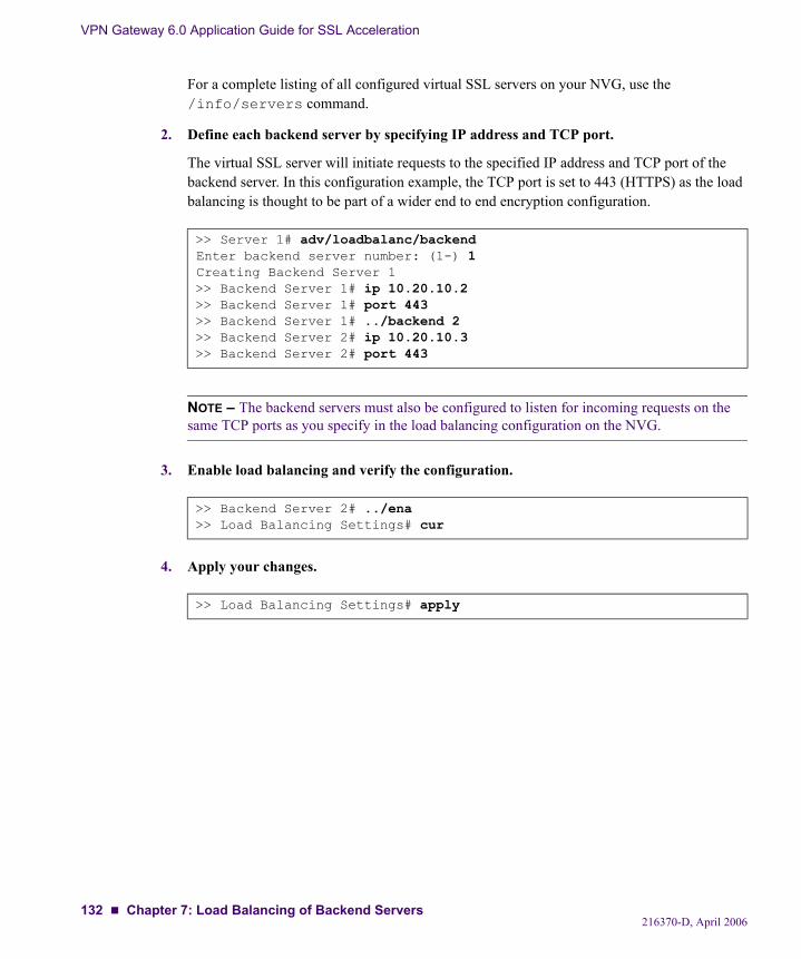
VPN Gateway 6.0 Application Guide for SSL Acceleration
For a complete listing of all configured virtual SSL servers on your NVG, use the /info/servers command.
2. Define each backend server by specifying IP address and TCP port.
The virtual SSL server will initiate requests to the specified IP address and TCP port of the backend server. In this configuration example, the TCP port is set to 443 (HTTPS) as the load balancing is thought to be part of a wider end to end encryption configuration.
NOTE – The backend servers must also be configured to listen for incoming requests on the same TCP ports as you specify in the load balancing configuration on the NVG.
3. Enable load balancing and verify the configuration.
4. Apply your changes.
>> Server 1# adv/loadbalanc/backendEnter backend server number: (1-) 1Creating Backend Server 1>> Backend Server 1# ip 10.20.10.2>> Backend Server 1# port 443>> Backend Server 1# ../backend 2>> Backend Server 2# ip 10.20.10.3>> Backend Server 2# port 443
>> Backend Server 2# ../ena>> Load Balancing Settings# cur
>> Load Balancing Settings# apply
216370-D, April 2006132 Chapter 7: Load Balancing of Backend Servers
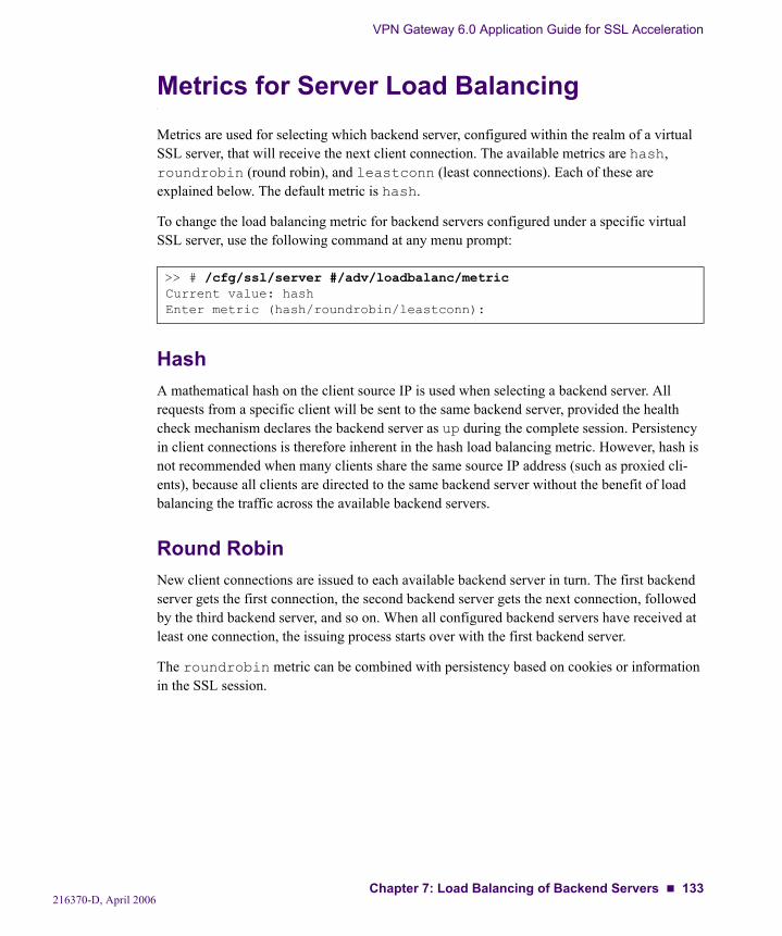
VPN Gateway 6.0 Application Guide for SSL Acceleration
Metrics for Server Load BalancingMetrics are used for selecting which backend server, configured within the realm of a virtual SSL server, that will receive the next client connection. The available metrics are hash, roundrobin (round robin), and leastconn (least connections). Each of these are explained below. The default metric is hash.
To change the load balancing metric for backend servers configured under a specific virtual SSL server, use the following command at any menu prompt:
HashA mathematical hash on the client source IP is used when selecting a backend server. All requests from a specific client will be sent to the same backend server, provided the health check mechanism declares the backend server as up during the complete session. Persistency in client connections is therefore inherent in the hash load balancing metric. However, hash is not recommended when many clients share the same source IP address (such as proxied cli-ents), because all clients are directed to the same backend server without the benefit of load balancing the traffic across the available backend servers.
Round RobinNew client connections are issued to each available backend server in turn. The first backend server gets the first connection, the second backend server gets the next connection, followed by the third backend server, and so on. When all configured backend servers have received at least one connection, the issuing process starts over with the first backend server.
The roundrobin metric can be combined with persistency based on cookies or information in the SSL session.
>> # /cfg/ssl/server #/adv/loadbalanc/metricCurrent value: hashEnter metric (hash/roundrobin/leastconn):
216370-D, April 2006Chapter 7: Load Balancing of Backend Servers 133
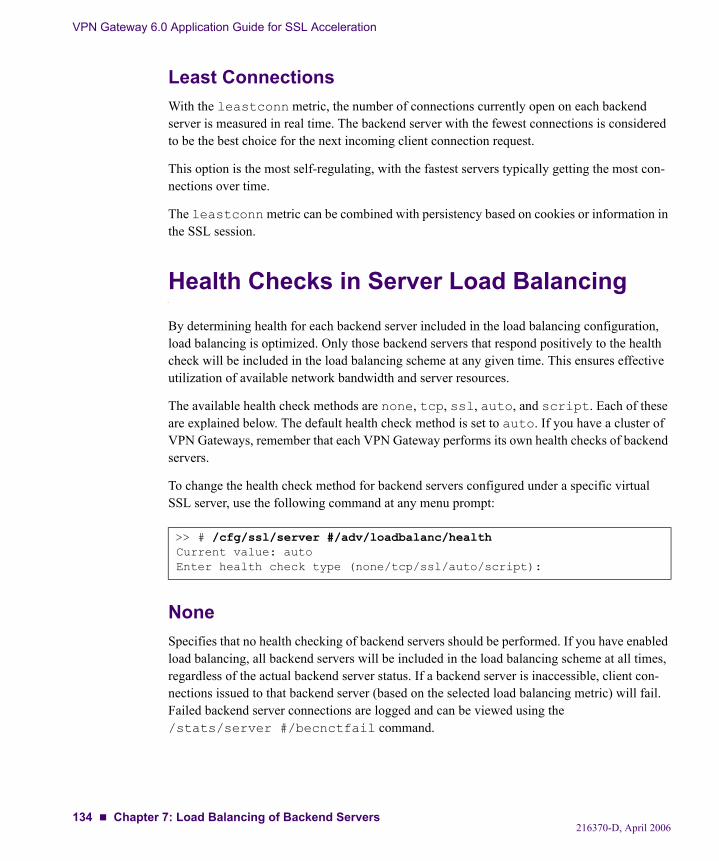
VPN Gateway 6.0 Application Guide for SSL Acceleration
Least ConnectionsWith the leastconn metric, the number of connections currently open on each backend server is measured in real time. The backend server with the fewest connections is considered to be the best choice for the next incoming client connection request.
This option is the most self-regulating, with the fastest servers typically getting the most con-nections over time.
The leastconn metric can be combined with persistency based on cookies or information in the SSL session.
Health Checks in Server Load BalancingBy determining health for each backend server included in the load balancing configuration, load balancing is optimized. Only those backend servers that respond positively to the health check will be included in the load balancing scheme at any given time. This ensures effective utilization of available network bandwidth and server resources.
The available health check methods are none, tcp, ssl, auto, and script. Each of these are explained below. The default health check method is set to auto. If you have a cluster of VPN Gateways, remember that each VPN Gateway performs its own health checks of backend servers.
To change the health check method for backend servers configured under a specific virtual SSL server, use the following command at any menu prompt:
NoneSpecifies that no health checking of backend servers should be performed. If you have enabled load balancing, all backend servers will be included in the load balancing scheme at all times, regardless of the actual backend server status. If a backend server is inaccessible, client con-nections issued to that backend server (based on the selected load balancing metric) will fail. Failed backend server connections are logged and can be viewed using the /stats/server #/becnctfail command.
>> # /cfg/ssl/server #/adv/loadbalanc/healthCurrent value: autoEnter health check type (none/tcp/ssl/auto/script):
216370-D, April 2006134 Chapter 7: Load Balancing of Backend Servers
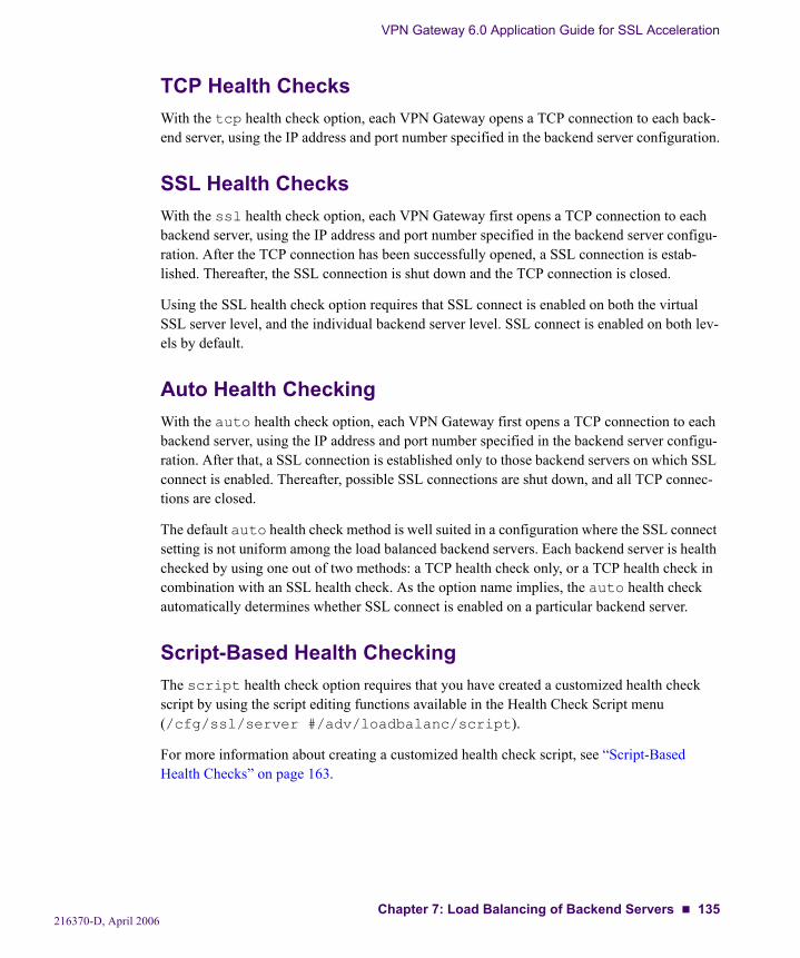
VPN Gateway 6.0 Application Guide for SSL Acceleration
TCP Health ChecksWith the tcp health check option, each VPN Gateway opens a TCP connection to each back-end server, using the IP address and port number specified in the backend server configuration.
SSL Health ChecksWith the ssl health check option, each VPN Gateway first opens a TCP connection to each backend server, using the IP address and port number specified in the backend server configu-ration. After the TCP connection has been successfully opened, a SSL connection is estab-lished. Thereafter, the SSL connection is shut down and the TCP connection is closed.
Using the SSL health check option requires that SSL connect is enabled on both the virtual SSL server level, and the individual backend server level. SSL connect is enabled on both lev-els by default.
Auto Health CheckingWith the auto health check option, each VPN Gateway first opens a TCP connection to each backend server, using the IP address and port number specified in the backend server configu-ration. After that, a SSL connection is established only to those backend servers on which SSL connect is enabled. Thereafter, possible SSL connections are shut down, and all TCP connec-tions are closed.
The default auto health check method is well suited in a configuration where the SSL connect setting is not uniform among the load balanced backend servers. Each backend server is health checked by using one out of two methods: a TCP health check only, or a TCP health check in combination with an SSL health check. As the option name implies, the auto health check automatically determines whether SSL connect is enabled on a particular backend server.
Script-Based Health CheckingThe script health check option requires that you have created a customized health check script by using the script editing functions available in the Health Check Script menu (/cfg/ssl/server #/adv/loadbalanc/script).
For more information about creating a customized health check script, see “Script-Based Health Checks” on page 163.
216370-D, April 2006Chapter 7: Load Balancing of Backend Servers 135

VPN Gateway 6.0 Application Guide for SSL Acceleration
String Matching in Server Load BalancingBy selecting string as the load balancing type, only those backend servers for which you have specified one or more match strings are included in the load balancing scheme. Further-more, load balancing of client connection requests among these backend servers occurs only if a match of the string definition is found in the specified location in a client connection request. If a match is found, the current load balancing metric (hash, round robin, or least connections) is applied. For more information about creating match strings and assigning them to individual backend servers, see “String-Based Load Balancing and Blocking” on page 151.
To change the load balancing method from all to string, use the following command at any menu prompt:
NOTE – String matching in load balancing overrides any persistency option (cookie or session), which are ignored.
>> # /cfg/ssl/server #/adv/loadbalanc/typeCurrent value: allEnter load balancing type (all/string): string
216370-D, April 2006136 Chapter 7: Load Balancing of Backend Servers
VPN Gateway 6.0 Application Guide for SSL Acceleration
Persistent Client Connections in Server Load BalancingWhen a virtual SSL server on the NVG is configured to perform load balancing of backend servers, a persistency strategy can be selected to ensure that all connections from a specific cli-ent reach the same backend server within the complete session. When a client initiates a con-nection request to establish a new session, the connection is issued to a backend server according to the load balancing metric you have selected (hash, round robin, or least connec-tions). For all subsequent client requests within an established session, however, the chosen persistency strategy comes into play and overrides the load balancing metric.
The available persistency options are none, cookie and session. Each of these are explained below. The default persistency option is set to none.
To change the persistency option for backend servers configured under a specific virtual SSL server, use the following command at any menu prompt:
>> # /cfg/ssl/server #/adv/loadbalanc/persistencCurrent value: noneEnter persistence (none/cookie/session):
216370-D, April 2006Chapter 7: Load Balancing of Backend Servers 137
VPN Gateway 6.0 Application Guide for SSL Acceleration
Cookie-Based PersistenceCookies are strings passed via HTTP from servers to browsers. Based on the mode of opera-tion, cookies are inserted by either the NVG or the backend server. After a client receives a cookie, a server can poll that cookie with a GET command, which allows the querying server to positively identify the client as the one that received the cookie earlier.
In the NVG, cookies are used to route client traffic back to the same physical backend server to maintain session persistence.
Permanent and Temporary CookiesCookies can be either permanent or temporary. A permanent cookie is stored on a client computer’s hard drive, with the cooperation of the client Web browser. On each subsequent request to the same site, the client Web browser will send the appropriate cookie. A permanent cookie may contain a user ID, or user preferences for a Web site that allows their pages to be customized.
A temporary cookie is only valid for a specific Web browser session, and expires as soon as the client Web browser is shut down. By default, the NVG uses temporary cookies, which are suf-ficient for maintaining persistency between clients and backend servers within a given session. You can however specify an expiration date or expiration time using the expires and expiresdel commands.
Client Browsers that do not Accept CookiesUnder normal conditions, most Web browsers are configured to accept cookies. However, if a client browser is configured to not accept cookies, you must use hash as the load-balancing metric to maintain session persistence.
With the persistence strategy set to cookie, session persistence for browsers that do not accept cookies will be based on the client source IP address instead.
Cookie FormatA cookie can be defined in the HTTP header or placed in the URL for hashing.
The NVG uses only cookies that are defined in the HTTP header. The cookie is defined as a “Name=Value” pair and can appear along with other parameters and cookies.
216370-D, April 2006138 Chapter 7: Load Balancing of Backend Servers
VPN Gateway 6.0 Application Guide for SSL Acceleration
Cookie PropertiesCookies are configured on the NVG by defining the following properties:
name (cookie name, maximum 254 bytes)
Identifies the cookie used by the virtual SSL server for persistence purposes. The maxi-mum length of a cookie name is restricted to 254 bytes.
domain (domain name)
Sets a domain name for the cookie (e.g. .example.com), to make sure the cookie gets returned to the server that initiated the cookie, even if the client browser sends the cookie to another server respond-ing to the same host name (e.g. www.example.com).
expires (date and time)
Sets an absolute expiration date for the cookie.
expiresdel (value in seconds)
Sets a time frame during which the cookie will be valid.
offset (integer value indicating number of bytes, 1-64)
Defines the starting point of the real cookie value within a longer string. The offset value directs the NVG to start looking for the real cookie value at the specified location in the string.
length (integer value indicating number of bytes, 0-64)
Defines the number of bytes to extract for the cookie value within a longer string. The specified length may vary depending on whether you want to include both backend server IP address and virtual server IP address (cookie length = 16) in the cookie information, or only backend server IP address (cookie length = 8).
Cookie properties are configured by using the related menu options in the Cookie Settings Menu:
>> Main# /cfg/ssl/server #/adv/loadbalanc/cookie[Cookie Settings Menu] mode - Set cookie mode name - Set cookie name domain - Set cookie domain expires - Set cookie expires expiresdel - Set cookie expires delta localvips - Configure other local VIPs offset - Set cookie value offset length - Set cookie value length cur - Display current settings
216370-D, April 2006Chapter 7: Load Balancing of Backend Servers 139
VPN Gateway 6.0 Application Guide for SSL Acceleration
Cookie Mode of OperationThe NVG supports the following modes of operation for cookie-based persistence:
insert
When a client sends a connection request without a cookie, the backend server responds with the requested data, and the NVG inserts a cookie into the data packet. The NVG embeds the IP address of the backend server that received the initial request into this cookie, and forwards the cookie to the client. The NVG then uses this cookie on all subse-quent connection requests from the same client (within a given session) to bind to the backend server that was first selected using the current load balancing metric.
Insert mode is the default mode of cookie operation.
passive
With passive mode, the backend server must be configured to embed a cookie in the response to the client request. The NVG will then look for this cookie in all subsequent connection requests (within a given session) from the same client, before establishing a connection to a backend server.
If you configure your backend server to include an IP address in hexadecimal form as the cookie value (requires a cookie length value of exactly 8 bytes), the NVG will use that IP address to direct all subsequent traffic within a given session to the same backend server.
If you configure your backend server to embed a string of characters as the cookie value, the NVG will perform a hash on the cookie value to direct all subsequent traffic within a given session to the same backend server.
rewrite
With rewrite mode, the backend server must be configured to return a special persistence cookie, which the NVG is configured to recognize. When recognized, the NVG intercepts the cookie and rewrites the value to include server-specific information before sending it on to the client. Subsequent connection requests (within a given session) from the same client are sent to the same backend server.
The cookie mode of operation can be changed by using the mode menu option in the Cookie Settings Menu:
>> Cookie Settings# modeCurrent value: iCookie mode (insert/passive/rewrite):
216370-D, April 2006140 Chapter 7: Load Balancing of Backend Servers
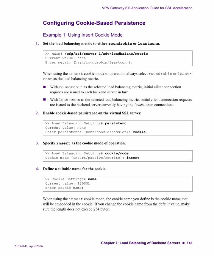
VPN Gateway 6.0 Application Guide for SSL Acceleration
Configuring Cookie-Based Persistence
Example 1: Using Insert Cookie Mode
1. Set the load balancing metric to either roundrobin or leastconn.
When using the insert cookie mode of operation, always select roundrobin or least-conn as the load balancing metric.
With roundrobin as the selected load balancing metric, initial client connection requests are issued to each backend server in turn.
With leastconn as the selected load balancing metric, initial client connection requests are issued to the backend server currently having the fewest open connections.
2. Enable cookie-based persistence on the virtual SSL server.
3. Specify insert as the cookie mode of operation.
4. Define a suitable name for the cookie.
When using the insert cookie mode, the cookie name you define is the cookie name that will be embedded in the cookie. If you change the cookie name from the default value, make sure the length does not exceed 254 bytes.
>> Main# /cfg/ssl/server 1/adv/loadbalanc/metricCurrent value: hashEnter metric (hash/roundrobin/leastconn):
>> Load Balancing Settings# persistencCurrent value: noneEnter persistence (none/cookie/session): cookie
>> Load Balancing Settings# cookie/modeCookie mode (insert/passive/rewrite): insert
>> Cookie Settings# nameCurrent value: ISDSSLEnter cookie name:
216370-D, April 2006Chapter 7: Load Balancing of Backend Servers 141

VPN Gateway 6.0 Application Guide for SSL Acceleration
5. Specify the offset value for the cookie.
With insert cookie mode, always set the cookie offset value to 1.
6. Specify the length value for the cookie.
To include only the backend server IP address, set the cookie length to 8 bytes (default value).
To include both the IP address of the backend server and the IP address of the Virtual server on the Application Switch, set the cookie length to 16 bytes.
7. Verify your cookie configuration.
8. Apply your settings.
>> Cookie Settings# offsetCurrent value: 1Enter starting point of cookie value [1-64]: 1
>> Cookie Settings# lengthCurrent value: 8Enter number of bytes to extract [0-64]:
>> Cookie Settings# curCollecting data, please wait...
Cookie Settings: Cookie mode = i <indicates "insert"> Cookie name = <your cookie name as embedded by the SSL VPN> Cookie value offset = 1 Cookie value length = <your specified extract length of 8 or 16>
>> Cookie Settings# applyChanges applied successfully.
216370-D, April 2006142 Chapter 7: Load Balancing of Backend Servers
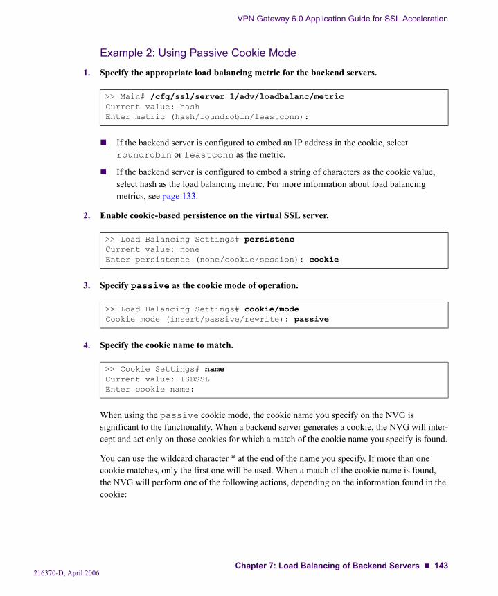
VPN Gateway 6.0 Application Guide for SSL Acceleration
Example 2: Using Passive Cookie Mode
1. Specify the appropriate load balancing metric for the backend servers.
If the backend server is configured to embed an IP address in the cookie, select roundrobin or leastconn as the metric.
If the backend server is configured to embed a string of characters as the cookie value, select hash as the load balancing metric. For more information about load balancing metrics, see page 133.
2. Enable cookie-based persistence on the virtual SSL server.
3. Specify passive as the cookie mode of operation.
4. Specify the cookie name to match.
When using the passive cookie mode, the cookie name you specify on the NVG is significant to the functionality. When a backend server generates a cookie, the NVG will inter-cept and act only on those cookies for which a match of the cookie name you specify is found.
You can use the wildcard character * at the end of the name you specify. If more than one cookie matches, only the first one will be used. When a match of the cookie name is found, the NVG will perform one of the following actions, depending on the information found in the cookie:
>> Main# /cfg/ssl/server 1/adv/loadbalanc/metricCurrent value: hashEnter metric (hash/roundrobin/leastconn):
>> Load Balancing Settings# persistencCurrent value: noneEnter persistence (none/cookie/session): cookie
>> Load Balancing Settings# cookie/modeCookie mode (insert/passive/rewrite): passive
>> Cookie Settings# nameCurrent value: ISDSSLEnter cookie name:
216370-D, April 2006Chapter 7: Load Balancing of Backend Servers 143

VPN Gateway 6.0 Application Guide for SSL Acceleration
If the backend server embeds an IP address in the cookie, the NVG will use the IP address information in the cookie to direct all subsequent traffic within a given session to the cor-responding backend server.
If the backend server embeds a string of characters as the cookie value, the NVG will per-form a hash on the cookie value. The NVG will then select a backend server and direct all subsequent traffic within a given session to the same backend server, based on the hashed cookie value. To perform the hash, the load balancing metric must be set to hash. If the load balancing metric is not set to hash, the cookie is ignored.
5. Specify the offset value for the cookie.
If an IP address is embedded in the cookie by the backend server, set the offset length to 1 byte.
If the backend server is configured to embed a string of characters as the cookie value, the offset value specifies at which point in the string the NVG should start to extract informa-tion used for the hashing key.
Example: For a cookie defined as sid=012345abcdef (sid being the cookie name, and 012345abcdef being the cookie value) and the offset value set to 5, the NVG will use information in the cookie value starting from the fifth byte (the character 4 in this example).
NOTE – The offset value (in bytes) must not exceed the byte length of the cookie value.
>> Cookie Settings# offsetCurrent value: 1Enter starting point of cookie value [1-64]:
216370-D, April 2006144 Chapter 7: Load Balancing of Backend Servers
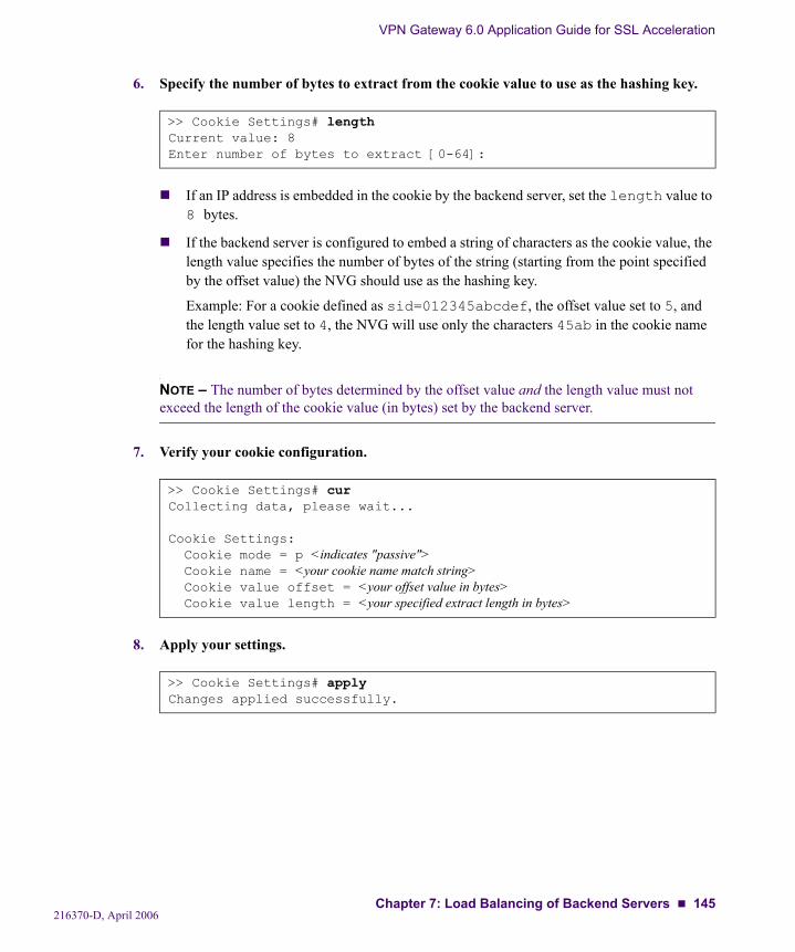
VPN Gateway 6.0 Application Guide for SSL Acceleration
6. Specify the number of bytes to extract from the cookie value to use as the hashing key.
If an IP address is embedded in the cookie by the backend server, set the length value to 8 bytes.
If the backend server is configured to embed a string of characters as the cookie value, the length value specifies the number of bytes of the string (starting from the point specified by the offset value) the NVG should use as the hashing key.
Example: For a cookie defined as sid=012345abcdef, the offset value set to 5, and the length value set to 4, the NVG will use only the characters 45ab in the cookie name for the hashing key.
NOTE – The number of bytes determined by the offset value and the length value must not exceed the length of the cookie value (in bytes) set by the backend server.
7. Verify your cookie configuration.
8. Apply your settings.
>> Cookie Settings# lengthCurrent value: 8Enter number of bytes to extract [0-64]:
>> Cookie Settings# curCollecting data, please wait...
Cookie Settings: Cookie mode = p <indicates "passive"> Cookie name = <your cookie name match string> Cookie value offset = <your offset value in bytes> Cookie value length = <your specified extract length in bytes>
>> Cookie Settings# applyChanges applied successfully.
216370-D, April 2006Chapter 7: Load Balancing of Backend Servers 145
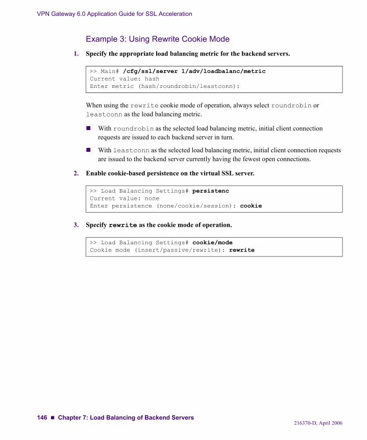
VPN Gateway 6.0 Application Guide for SSL Acceleration
Example 3: Using Rewrite Cookie Mode
1. Specify the appropriate load balancing metric for the backend servers.
When using the rewrite cookie mode of operation, always select roundrobin or leastconn as the load balancing metric.
With roundrobin as the selected load balancing metric, initial client connection requests are issued to each backend server in turn.
With leastconn as the selected load balancing metric, initial client connection requests are issued to the backend server currently having the fewest open connections.
2. Enable cookie-based persistence on the virtual SSL server.
3. Specify rewrite as the cookie mode of operation.
>> Main# /cfg/ssl/server 1/adv/loadbalanc/metricCurrent value: hashEnter metric (hash/roundrobin/leastconn):
>> Load Balancing Settings# persistencCurrent value: noneEnter persistence (none/cookie/session): cookie
>> Load Balancing Settings# cookie/modeCookie mode (insert/passive/rewrite): rewrite
216370-D, April 2006146 Chapter 7: Load Balancing of Backend Servers
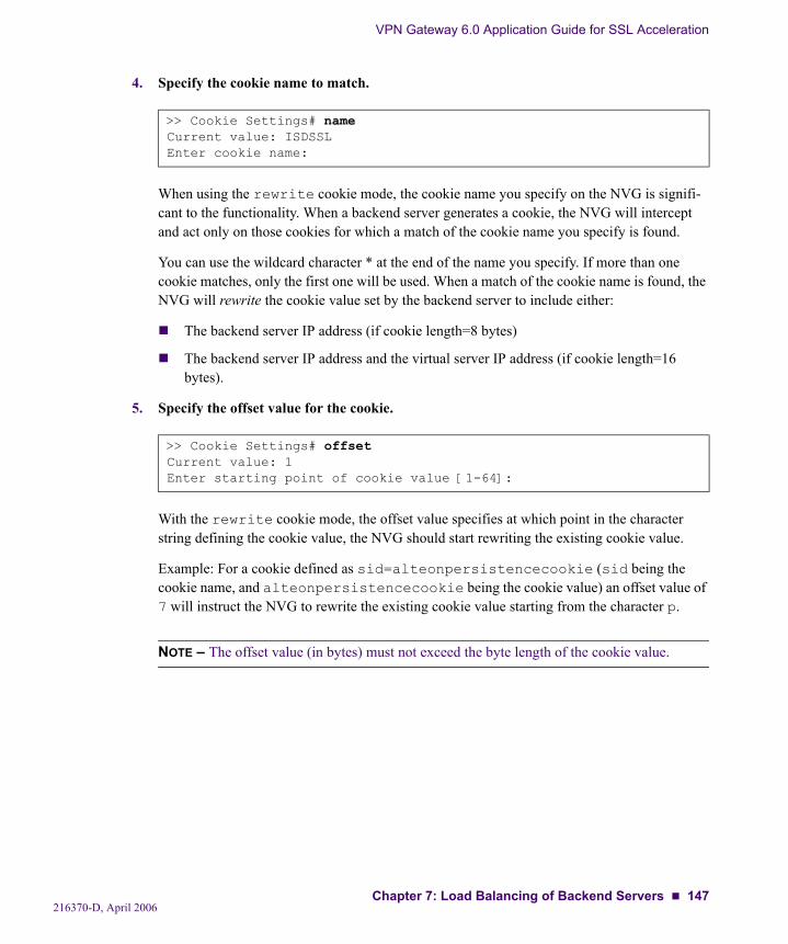
VPN Gateway 6.0 Application Guide for SSL Acceleration
4. Specify the cookie name to match.
When using the rewrite cookie mode, the cookie name you specify on the NVG is signifi-cant to the functionality. When a backend server generates a cookie, the NVG will intercept and act only on those cookies for which a match of the cookie name you specify is found.
You can use the wildcard character * at the end of the name you specify. If more than one cookie matches, only the first one will be used. When a match of the cookie name is found, the NVG will rewrite the cookie value set by the backend server to include either:
The backend server IP address (if cookie length=8 bytes)
The backend server IP address and the virtual server IP address (if cookie length=16 bytes).
5. Specify the offset value for the cookie.
With the rewrite cookie mode, the offset value specifies at which point in the character string defining the cookie value, the NVG should start rewriting the existing cookie value.
Example: For a cookie defined as sid=alteonpersistencecookie (sid being the cookie name, and alteonpersistencecookie being the cookie value) an offset value of 7 will instruct the NVG to rewrite the existing cookie value starting from the character p.
NOTE – The offset value (in bytes) must not exceed the byte length of the cookie value.
>> Cookie Settings# nameCurrent value: ISDSSLEnter cookie name:
>> Cookie Settings# offsetCurrent value: 1Enter starting point of cookie value [1-64]:
216370-D, April 2006Chapter 7: Load Balancing of Backend Servers 147
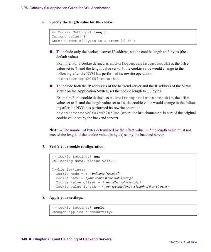
VPN Gateway 6.0 Application Guide for SSL Acceleration
6. Specify the length value for the cookie.
To include only the backend server IP address, set the cookie length to 8 bytes (the default value).
Example: For a cookie defined as sid=alteonpersistencecookie, the offset value set to 7, and the length value set to 8, the cookie value would change to the following after the NVG has performed its rewrite operation: sid=alteoncdb20f04ncecookie
To include both the IP addresses of the backend server and the IP address of the Virtual server on the Application Switch, set the cookie length to 16 bytes.
Example: For a cookie defined as sid=alteonpersistencecookie, the offset value set to 7, and the length value set to 16, the cookie value would change to the follow-ing after the NVG has performed its rewrite operation: sid=alteoncdb20f04cdb20f0ae (where the last character e is part of the original cookie value set by the backend server).
NOTE – The number of bytes determined by the offset value and the length value must not exceed the length of the cookie value (in bytes) set by the backend server.
7. Verify your cookie configuration.
8. Apply your settings.
>> Cookie Settings# lengthCurrent value: 8Enter number of bytes to extract [0-64]:
>> Cookie Settings# curCollecting data, please wait...
Cookie Settings: Cookie mode = r <indicates "rewrite"> Cookie name = <your cookie name match string> Cookie value offset = <your offset value in bytes> Cookie value length = <your specified extract length of 8 or 16 bytes>
>> Cookie Settings# applyChanges applied successfully.
216370-D, April 2006148 Chapter 7: Load Balancing of Backend Servers
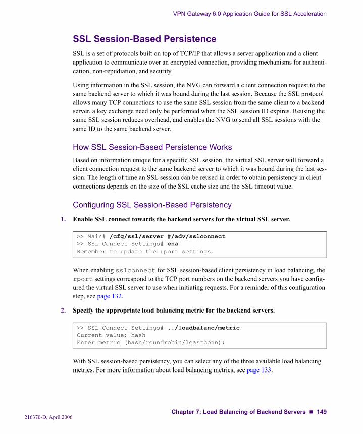
VPN Gateway 6.0 Application Guide for SSL Acceleration
SSL Session-Based PersistenceSSL is a set of protocols built on top of TCP/IP that allows a server application and a client application to communicate over an encrypted connection, providing mechanisms for authenti-cation, non-repudiation, and security.
Using information in the SSL session, the NVG can forward a client connection request to the same backend server to which it was bound during the last session. Because the SSL protocol allows many TCP connections to use the same SSL session from the same client to a backend server, a key exchange need only be performed when the SSL session ID expires. Reusing the same SSL session reduces overhead, and enables the NVG to send all SSL sessions with the same ID to the same backend server.
How SSL Session-Based Persistence WorksBased on information unique for a specific SSL session, the virtual SSL server will forward a client connection request to the same backend server to which it was bound during the last ses-sion. The length of time an SSL session can be reused in order to obtain persistency in client connections depends on the size of the SSL cache size and the SSL timeout value.
Configuring SSL Session-Based Persistency
1. Enable SSL connect towards the backend servers for the virtual SSL server.
When enabling sslconnect for SSL session-based client persistency in load balancing, the rport settings correspond to the TCP port numbers on the backend servers you have config-ured the virtual SSL server to use when initiating requests. For a reminder of this configuration step, see page 132.
2. Specify the appropriate load balancing metric for the backend servers.
With SSL session-based persistency, you can select any of the three available load balancing metrics. For more information about load balancing metrics, see page 133.
>> Main# /cfg/ssl/server #/adv/sslconnect>> SSL Connect Settings# enaRemember to update the rport settings.
>> SSL Connect Settings# ../loadbalanc/metricCurrent value: hashEnter metric (hash/roundrobin/leastconn):
216370-D, April 2006Chapter 7: Load Balancing of Backend Servers 149
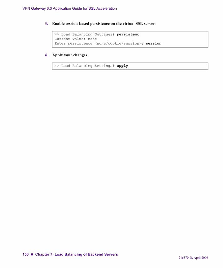
VPN Gateway 6.0 Application Guide for SSL Acceleration
3. Enable session-based persistence on the virtual SSL server.
4. Apply your changes.
>> Load Balancing Settings# persistencCurrent value: noneEnter persistence (none/cookie/session): session
>> Load Balancing Settings# apply
216370-D, April 2006150 Chapter 7: Load Balancing of Backend Servers
CHAPTER 8String-Based Load Balancing and Blocking
This chapter provides information about creating match strings used to customize the load bal-ancing of backend servers. In the following procedure, many of the backend server load bal-ancing options are left to their default values. See “Additional Match String Options” on page 161 for more options.
Creating Match StringsBy using the menu options in the Load Balancing Strings menu, you can define up to 128 match strings per virtual server. Match strings are identified by their index number, and these index numbers are assigned to backend servers for string-based load balancing. To effectively perform string-based load balancing, the same match string index number must be assigned to at least two backend servers. When a match of the defined string is found in a client connection request, only those backend servers to which the match string has been assigned are included in the load balancing scheme. The matching client connection request is then issued to one of these backend servers, based on the current load balancing metric (hash, round robin, or least connections).
NOTE – If a client connection request does not match any string assigned to any of the backend servers, the client connection is terminated.
The menu options in the Load Balancing Strings menu are also used for creating blocking strings. A blocking string is used for blocking client requests containing data that matches a string of data as defined in the blocking string. If a match is found, the client connection request is terminated. Unlike match strings, specified blocking strings apply to all backend servers configured under a particular virtual SSL server. The blocking feature can be useful in order to protect the backend servers from being infected with the “Code Red” worm, for example.
216370-D, April 2006151
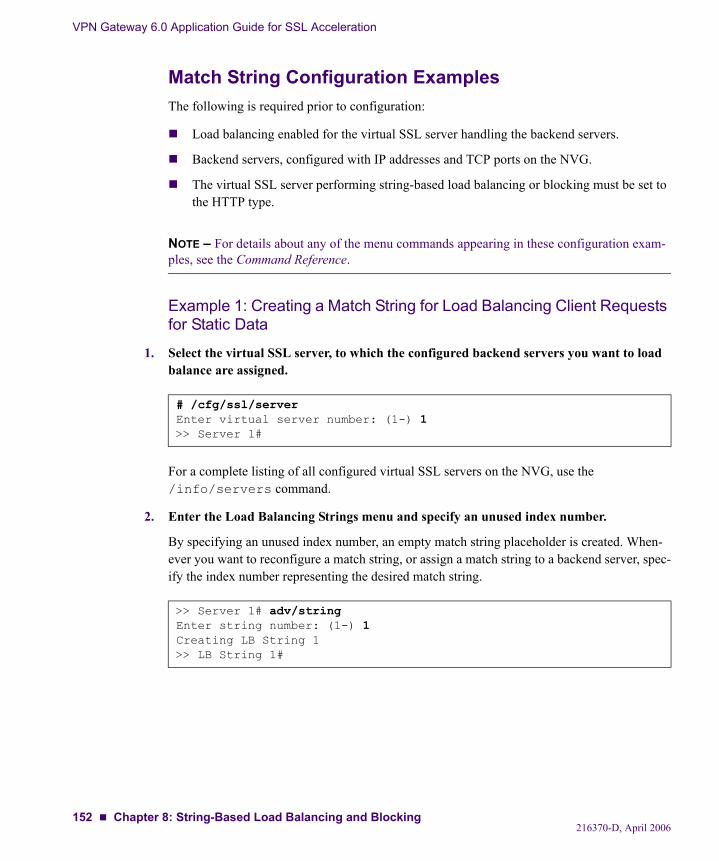
VPN Gateway 6.0 Application Guide for SSL Acceleration
Match String Configuration ExamplesThe following is required prior to configuration:
Load balancing enabled for the virtual SSL server handling the backend servers.
Backend servers, configured with IP addresses and TCP ports on the NVG.
The virtual SSL server performing string-based load balancing or blocking must be set to the HTTP type.
NOTE – For details about any of the menu commands appearing in these configuration exam-ples, see the Command Reference.
Example 1: Creating a Match String for Load Balancing Client Requests for Static Data
1. Select the virtual SSL server, to which the configured backend servers you want to load balance are assigned.
For a complete listing of all configured virtual SSL servers on the NVG, use the /info/servers command.
2. Enter the Load Balancing Strings menu and specify an unused index number.
By specifying an unused index number, an empty match string placeholder is created. When-ever you want to reconfigure a match string, or assign a match string to a backend server, spec-ify the index number representing the desired match string.
# /cfg/ssl/serverEnter virtual server number: (1-) 1>> Server 1#
>> Server 1# adv/stringEnter string number: (1-) 1Creating LB String 1>> LB String 1#
216370-D, April 2006152 Chapter 8: String-Based Load Balancing and Blocking

VPN Gateway 6.0 Application Guide for SSL Acceleration
3. Define a first match string to be used in load balancing.
The wildcard character “*” can be used for any match string. Only one match string can be defined for each match string index number. Instead, you can assign more than one match string to a backend server by separating the corresponding match string index numbers with a comma (,).
4. Specify the client request location(s), in which the NVG will search for a match.
The NVG will search for matches only in the locations you specify. The client request connec-tion is issued to a load balanced backend server according to the current metric if a match is found in one or several of the specified locations. For load balancing to occur, it is thus not required that matches be found in all the specified locations.
A match location can be either a header name in a HTTP request (such as User-Agent), or an HTTP method (such as GET). When specifying URL as a match location, all valid HTTP methods are included in the search which saves you from having to enter each method name explicitly. For more information about valid match locations, see the location command in the “Load Balancing Strings Configuration” section in the Command Reference.
5. Define a second match string.
6. Specify the client request location(s) for the second match string.
>> LB String 1# matchCurrent value: <not set>Enter match string (may contain *): *.GIF
>> LB String 1# locationCurrent value: ""Enter match locations (separated by comma): URL
>> LB String 1# ../string 2Creating LB String 2>> LB String 2#Current value: <not set>Enter match string (may contain *): *.JPG
>> LB String 2# locationCurrent value: ""Enter match locations (separated by comma): URL
216370-D, April 2006Chapter 8: String-Based Load Balancing and Blocking 153
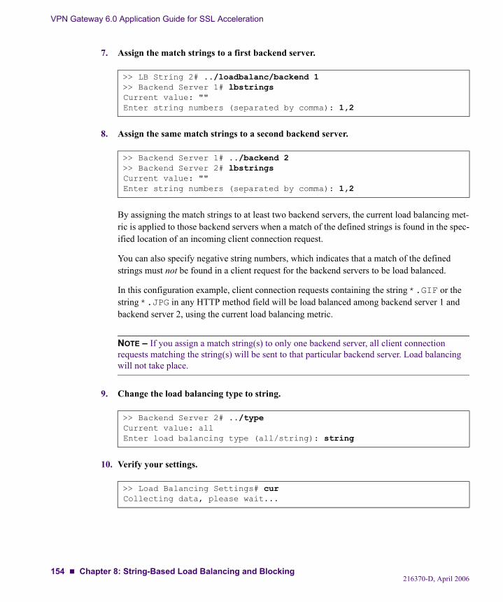
VPN Gateway 6.0 Application Guide for SSL Acceleration
7. Assign the match strings to a first backend server.
8. Assign the same match strings to a second backend server.
By assigning the match strings to at least two backend servers, the current load balancing met-ric is applied to those backend servers when a match of the defined strings is found in the spec-ified location of an incoming client connection request.
You can also specify negative string numbers, which indicates that a match of the defined strings must not be found in a client request for the backend servers to be load balanced.
In this configuration example, client connection requests containing the string *.GIF or the string *.JPG in any HTTP method field will be load balanced among backend server 1 and backend server 2, using the current load balancing metric.
NOTE – If you assign a match string(s) to only one backend server, all client connection requests matching the string(s) will be sent to that particular backend server. Load balancing will not take place.
9. Change the load balancing type to string.
10. Verify your settings.
>> LB String 2# ../loadbalanc/backend 1>> Backend Server 1# lbstringsCurrent value: ""Enter string numbers (separated by comma): 1,2
>> Backend Server 1# ../backend 2>> Backend Server 2# lbstringsCurrent value: ""Enter string numbers (separated by comma): 1,2
>> Backend Server 2# ../typeCurrent value: allEnter load balancing type (all/string): string
>> Load Balancing Settings# curCollecting data, please wait...
216370-D, April 2006154 Chapter 8: String-Based Load Balancing and Blocking
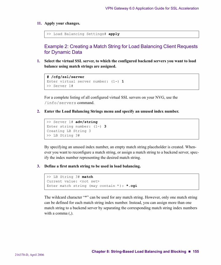
VPN Gateway 6.0 Application Guide for SSL Acceleration
11. Apply your changes.
Example 2: Creating a Match String for Load Balancing Client Requests for Dynamic Data
1. Select the virtual SSL server, to which the configured backend servers you want to load balance using match strings are assigned.
For a complete listing of all configured virtual SSL servers on your NVG, use the /info/servers command.
2. Enter the Load Balancing Strings menu and specify an unused index number.
By specifying an unused index number, an empty match string placeholder is created. When-ever you want to reconfigure a match string, or assign a match string to a backend server, spec-ify the index number representing the desired match string.
3. Define a first match string to be used in load balancing.
The wildcard character “*” can be used for any match string. However, only one match string can be defined for each match string index number. Instead, you can assign more than one match string to a backend server by separating the corresponding match string index numbers with a comma (,).
>> Load Balancing Settings# apply
# /cfg/ssl/serverEnter virtual server number: (1-) 1>> Server 1#
>> Server 1# adv/stringEnter string number: (1-) 3Creating LB String 3>> LB String 3#
>> LB String 3# matchCurrent value: <not set>Enter match string (may contain *): *.cgi
216370-D, April 2006Chapter 8: String-Based Load Balancing and Blocking 155
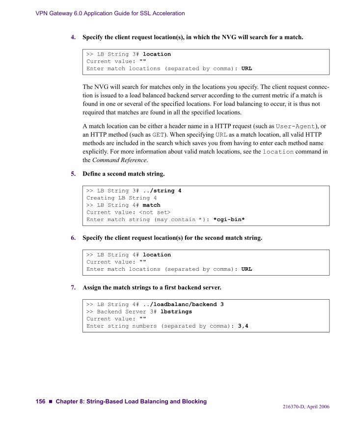
VPN Gateway 6.0 Application Guide for SSL Acceleration
4. Specify the client request location(s), in which the NVG will search for a match.
The NVG will search for matches only in the locations you specify. The client request connec-tion is issued to a load balanced backend server according to the current metric if a match is found in one or several of the specified locations. For load balancing to occur, it is thus not required that matches are found in all the specified locations.
A match location can be either a header name in a HTTP request (such as User-Agent), or an HTTP method (such as GET). When specifying URL as a match location, all valid HTTP methods are included in the search which saves you from having to enter each method name explicitly. For more information about valid match locations, see the location command in the Command Reference.
5. Define a second match string.
6. Specify the client request location(s) for the second match string.
7. Assign the match strings to a first backend server.
>> LB String 3# locationCurrent value: ""Enter match locations (separated by comma): URL
>> LB String 3# ../string 4Creating LB String 4>> LB String 4# matchCurrent value: <not set>Enter match string (may contain *): *cgi-bin*
>> LB String 4# locationCurrent value: ""Enter match locations (separated by comma): URL
>> LB String 4# ../loadbalanc/backend 3>> Backend Server 3# lbstringsCurrent value: ""Enter string numbers (separated by comma): 3,4
216370-D, April 2006156 Chapter 8: String-Based Load Balancing and Blocking
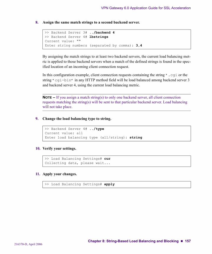
VPN Gateway 6.0 Application Guide for SSL Acceleration
8. Assign the same match strings to a second backend server.
By assigning the match strings to at least two backend servers, the current load balancing met-ric is applied to those backend servers when a match of the defined strings is found in the spec-ified location of an incoming client connection request.
In this configuration example, client connection requests containing the string *.cgi or the string *cgi-bin* in any HTTP method field will be load balanced among backend server 3 and backend server 4, using the current load balancing metric.
NOTE – If you assign a match string(s) to only one backend server, all client connection requests matching the string(s) will be sent to that particular backend server. Load balancing will not take place.
9. Change the load balancing type to string.
10. Verify your settings.
11. Apply your changes.
>> Backend Server 3# ../backend 4>> Backend Server 4# lbstringsCurrent value: ""Enter string numbers (separated by comma): 3,4
>> Backend Server 4# ../typeCurrent value: allEnter load balancing type (all/string): string
>> Load Balancing Settings# curCollecting data, please wait...
>> Load Balancing Settings# apply
216370-D, April 2006Chapter 8: String-Based Load Balancing and Blocking 157
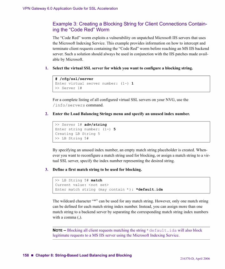
VPN Gateway 6.0 Application Guide for SSL Acceleration
Example 3: Creating a Blocking String for Client Connections Contain-ing the “Code Red” WormThe “Code Red” worm exploits a vulnerability on unpatched Microsoft IIS servers that uses the Microsoft Indexing Service. This example provides information on how to intercept and terminate client requests containing the “Code Red” worm before reaching an MS IIS backend server. Such a solution should always be used in conjunction with the IIS patches made avail-able by Microsoft.
1. Select the virtual SSL server for which you want to configure a blocking string.
For a complete listing of all configured virtual SSL servers on your NVG, use the /info/servers command.
2. Enter the Load Balancing Strings menu and specify an unused index number.
By specifying an unused index number, an empty match string placeholder is created. When-ever you want to reconfigure a match string used for blocking, or assign a match string to a vir-tual SSL server, specify the index number representing the desired string.
3. Define a first match string to be used for blocking.
The wildcard character “*” can be used for any match string. However, only one match string can be defined for each match string index number. Instead, you can assign more than one match string to a backend server by separating the corresponding match string index numbers with a comma (,).
NOTE – Blocking all client requests matching the string *default.ida will also block legitimate requests to a MS IIS server using the Microsoft Indexing Service.
# /cfg/ssl/serverEnter virtual server number: (1-) 1>> Server 1#
>> Server 1# adv/stringEnter string number: (1-) 5Creating LB String 5>> LB String 5#
>> LB String 5# matchCurrent value: <not set>Enter match string (may contain *): *default.ida
216370-D, April 2006158 Chapter 8: String-Based Load Balancing and Blocking
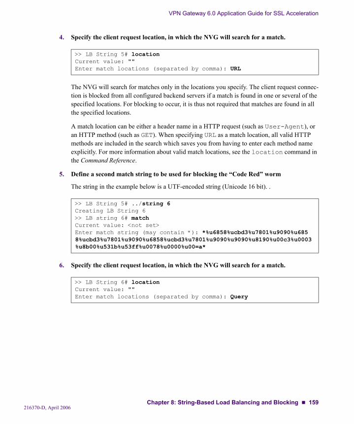
VPN Gateway 6.0 Application Guide for SSL Acceleration
4. Specify the client request location, in which the NVG will search for a match.
The NVG will search for matches only in the locations you specify. The client request connec-tion is blocked from all configured backend servers if a match is found in one or several of the specified locations. For blocking to occur, it is thus not required that matches are found in all the specified locations.
A match location can be either a header name in a HTTP request (such as User-Agent), or an HTTP method (such as GET). When specifying URL as a match location, all valid HTTP methods are included in the search which saves you from having to enter each method name explicitly. For more information about valid match locations, see the location command in the Command Reference.
5. Define a second match string to be used for blocking the “Code Red” worm
The string in the example below is a UTF-encoded string (Unicode 16 bit). .
6. Specify the client request location, in which the NVG will search for a match.
>> LB String 5# locationCurrent value: ""Enter match locations (separated by comma): URL
>> LB String 5# ../string 6Creating LB String 6>> LB string 6# matchCurrent value: <not set>Enter match string (may contain *): *%u6858%ucbd3%u7801%u9090%u6858%ucbd3%u7801%u9090%u6858%ucbd3%u7801%u9090%u9090%u8190%u00c3%u0003%u8b00%u531b%u53ff%u0078%u0000%u00=a*
>> LB String 6# locationCurrent value: ""Enter match locations (separated by comma): Query
216370-D, April 2006Chapter 8: String-Based Load Balancing and Blocking 159
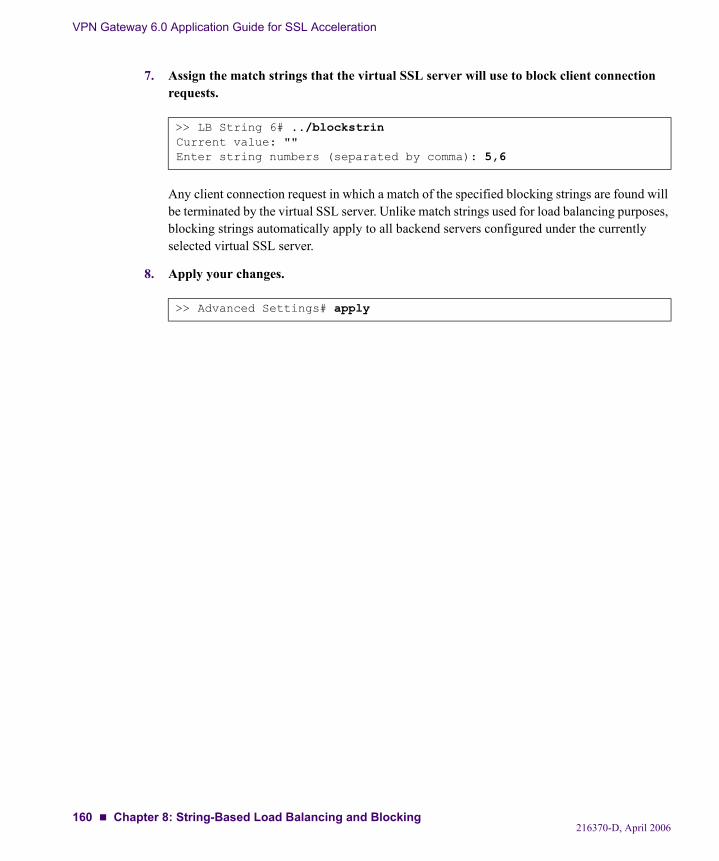
VPN Gateway 6.0 Application Guide for SSL Acceleration
7. Assign the match strings that the virtual SSL server will use to block client connection requests.
Any client connection request in which a match of the specified blocking strings are found will be terminated by the virtual SSL server. Unlike match strings used for load balancing purposes, blocking strings automatically apply to all backend servers configured under the currently selected virtual SSL server.
8. Apply your changes.
>> LB String 6# ../blockstrinCurrent value: ""Enter string numbers (separated by comma): 5,6
>> Advanced Settings# apply
216370-D, April 2006160 Chapter 8: String-Based Load Balancing and Blocking
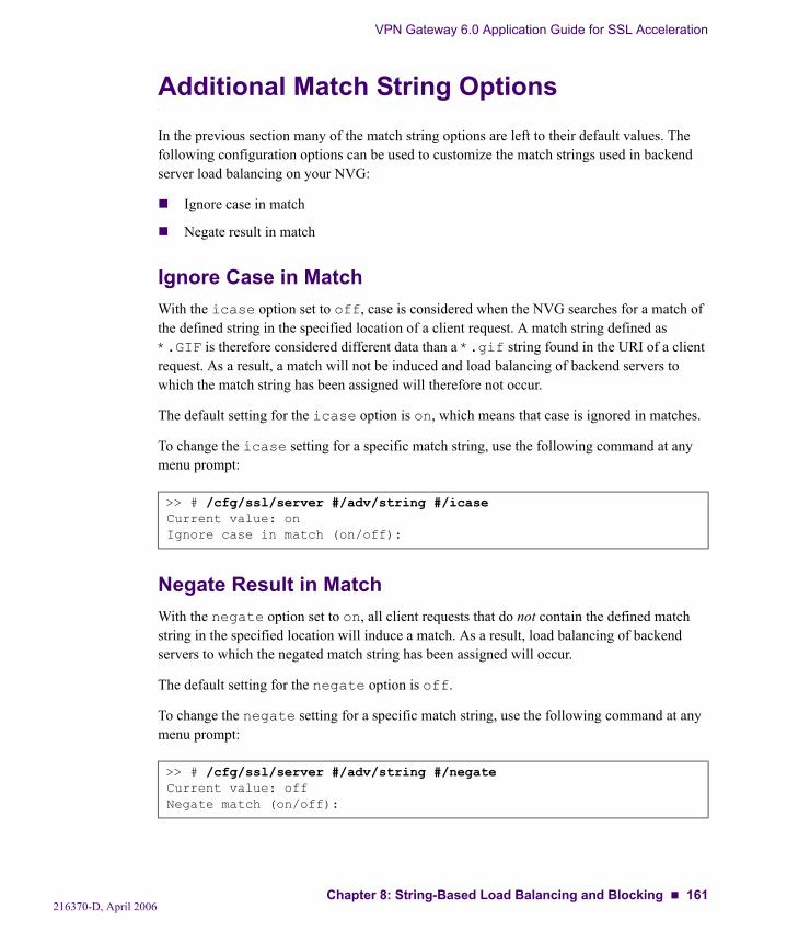
VPN Gateway 6.0 Application Guide for SSL Acceleration
Additional Match String OptionsIn the previous section many of the match string options are left to their default values. The following configuration options can be used to customize the match strings used in backend server load balancing on your NVG:
Ignore case in match
Negate result in match
Ignore Case in MatchWith the icase option set to off, case is considered when the NVG searches for a match of the defined string in the specified location of a client request. A match string defined as *.GIF is therefore considered different data than a *.gif string found in the URI of a client request. As a result, a match will not be induced and load balancing of backend servers to which the match string has been assigned will therefore not occur.
The default setting for the icase option is on, which means that case is ignored in matches.
To change the icase setting for a specific match string, use the following command at any menu prompt:
Negate Result in MatchWith the negate option set to on, all client requests that do not contain the defined match string in the specified location will induce a match. As a result, load balancing of backend servers to which the negated match string has been assigned will occur.
The default setting for the negate option is off.
To change the negate setting for a specific match string, use the following command at any menu prompt:
>> # /cfg/ssl/server #/adv/string #/icaseCurrent value: onIgnore case in match (on/off):
>> # /cfg/ssl/server #/adv/string #/negateCurrent value: offNegate match (on/off):
216370-D, April 2006Chapter 8: String-Based Load Balancing and Blocking 161
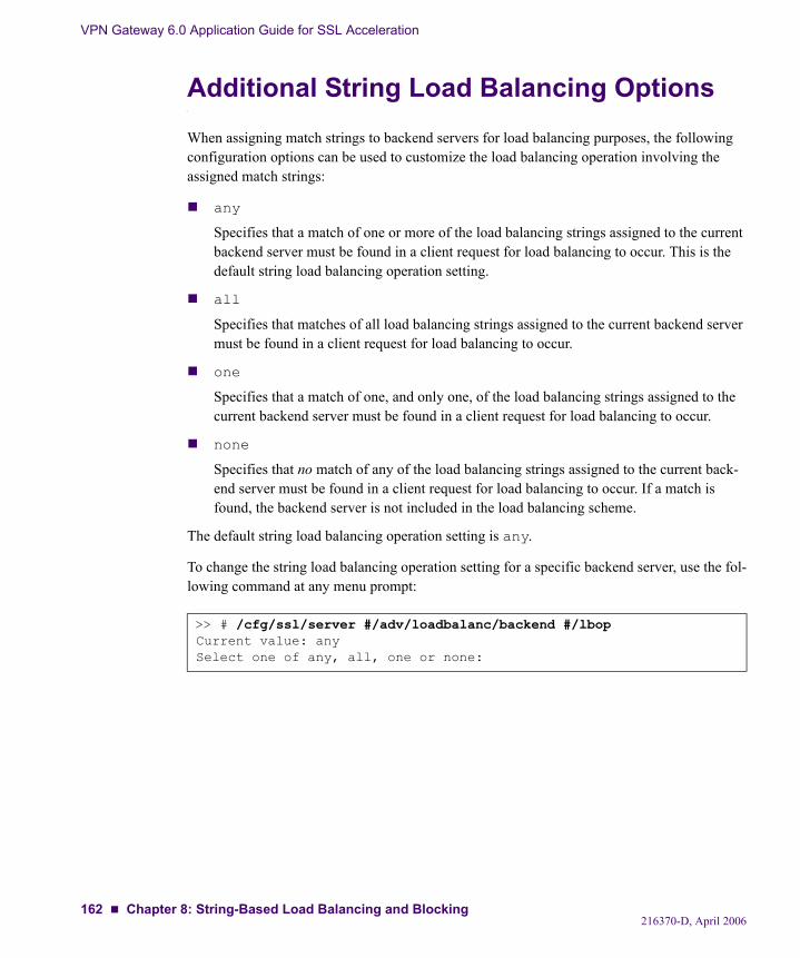
VPN Gateway 6.0 Application Guide for SSL Acceleration
Additional String Load Balancing OptionsWhen assigning match strings to backend servers for load balancing purposes, the following configuration options can be used to customize the load balancing operation involving the assigned match strings:
any
Specifies that a match of one or more of the load balancing strings assigned to the current backend server must be found in a client request for load balancing to occur. This is the default string load balancing operation setting.
all
Specifies that matches of all load balancing strings assigned to the current backend server must be found in a client request for load balancing to occur.
one
Specifies that a match of one, and only one, of the load balancing strings assigned to the current backend server must be found in a client request for load balancing to occur.
none
Specifies that no match of any of the load balancing strings assigned to the current back-end server must be found in a client request for load balancing to occur. If a match is found, the backend server is not included in the load balancing scheme.
The default string load balancing operation setting is any.
To change the string load balancing operation setting for a specific backend server, use the fol-lowing command at any menu prompt:
>> # /cfg/ssl/server #/adv/loadbalanc/backend #/lbopCurrent value: anySelect one of any, all, one or none:
216370-D, April 2006162 Chapter 8: String-Based Load Balancing and Blocking
CHAPTER 9Script-Based Health Checks
If you have enabled load balancing of the backend servers for a virtual SSL server, you also have the option to select a health check type. The load balancing decisions will in part be based on the outcome of the backend server health checks, which are performed at regular intervals (the default health check interval is 10 seconds).
The default health check type is auto, which uses a built-in preconfigured script. For more information about the built-in scripts used with auto health checking, see page 174. Other available health check types include tcp, ssl and script (besides the none option). The health check type is selected using the following command: /cfg/ssl/server #/adv/loadbalanc/health
For more information about available health check types, see the “Load Balancing Settings” section in the Command Reference.
If you select script as the health check type, it is assumed that you have created a custom-ized script by using the script editing functions available in the Health Check Script menu. This chapter provides instructions and examples for creating your own customized health check scripts.
The script health check mechanism is based around a script language which can establish both TCP and SSL connections to the backend servers, and send and expect data on those connec-tions. If a single script item in a health check script fails, the entire script fails and the backend server is reported as down.
216370-D, April 2006163
VPN Gateway 6.0 Application Guide for SSL Acceleration
Customized Health Check ScriptsThe Health Check Script menu is used for creating customized health check scripts. The script editing functions available in the Health Check menu consist of a number of script commands. Timeout values can be set individually for each script command. Arguments can also be defined for a few script commands.
The Health Check Script menu is accessed by using the following command: /cfg/ssl/server #/adv/loadbalanc/script
Script CommandsA timeout value can be set for each script command. The timeout value defines the maximum number of seconds in which the particular operation must complete for the health check to be considered successful.
Arguments can be defined for the open, send, and expect script commands. The argument associates a data field to one of these commands. The argument can consist of an IP address and TCP port number combination (open command), a HTTP GET request (send com-mand), or an extended POSIX regular expression (expect command).
The following script commands and parameters are available:
auto_open <timeout>
This command will first perform a check to see whether SSL connect is enabled on the virtual SSL server for which you have set the health check type to script.
If SSL connect is not enabled on the virtual SSL server, the command will open a TCP connection to each of the load balanced backend server.
If SSL connect is enabled on the virtual SSL server, the command will perform a second check to see whether SSL connect is enabled on each of the backend servers included in the load balancing configuration. For those backend servers on which SSL connect is enabled, the auto_open command first opens a TCP connection and then establishes a full SSL session. For those backend servers on which SSL connect is not enabled, the auto_open command will only open a TCP connection.
When creating a customized health-check script, you are recommended to use the auto_open (and corresponding auto_close) script command in a configuration where the SSL connect setting of the backend servers is not uniform. Given these condi-tions, using the auto_open and auto_close script commands will ensure the highest level of accuracy in the health checking of backend servers.
216370-D, April 2006164 Chapter 9: Script-Based Health Checks
VPN Gateway 6.0 Application Guide for SSL Acceleration
open <timeout> <argument (IPAddress:Port)>
This command opens a TCP connection to the load balanced backend servers, or to the IP address specified in the argument. The timeout value (in seconds) defines the time frame for establishing the TCP connection. The argument is optional, and if no argument is spec-ified the backend servers specified in the Backend Servers menu (cfg/ssl/server #/adv/loadbalanc/backend) are implicit. If an argument is specified, the argument must be stated as IP ADDRESS:PORT.Example: 192.168.0.4:443
ssl_open <timeout>
This command establishes a full SSL session to the load balanced backend servers, or to the IP address specified in the argument for the preceding open script command. Note that the ssl_open command cannot be used independently; it must be preceded by the regular open script command. (Likewise, the ssl_close command must be followed by the regular close script command.) The SSL parameters used for the SSL session are the same as the ones specified in the SSL Connect Settings menu.
The timeout value (in seconds) defines the time frame for establishing the SSL connec-tion. If the backend servers are under a heavy load this may take a considerable amount of time. The argument field is ignored for the ssl_open script command because the com-mand must be preceded by the regular open command. If the preceding open command is used together with an argument, the SSL session is established to the IP address and port that was specified in that argument.
send <timeout> <argument (HTTP request)>
This command sends data on the established connection, regardless of whether the con-nection is an ordinary TCP connection or an SSL connection. If the connection is an SSL connection, all transmitted data is encrypted. See Script Example 2 on page 171 for an example argument that can be used with the send script command.
expect <timeout> <argument (extended POSIX regular expressions)>
This command reads data from the established connection and matches the received data against the extended POSIX regular expression given as an argument. If the established connection is an SSL connection, the received data is decrypted. The expect script com-mand is often preceded by the send script command, but as Script Example 1 on page 167 shows this is not a requirement. For more information about defining an argu-ment for the expect command, see “Extended POSIX Regular Expressions” on page 166.
ssl_close <timeout>
This command performs an SSL shutdown on the most recent SSL connection that was established using the ssl_open script command.
216370-D, April 2006Chapter 9: Script-Based Health Checks 165
VPN Gateway 6.0 Application Guide for SSL Acceleration
close <timeout>
This command terminates the most recent TCP connection that was established using the open script command. Both the close command and the ssl_close command oper-ate on the most recently opened connection. Only one connection at a time can be open within a health check script. However, the script may contain more than one consecutive series of open and close sequences (as illustrated in Script Example 1 on page 167).
auto_close <timeout>
This command will first perform an SSL shutdown on the most recent SSL connection, if established, and then continue with terminating the most recent TCP connection. Just as with the corresponding auto_open script command, you are recommended to use the auto_close command in a configuration where the SSL connect setting of the backend servers is not uniform. Given these conditions, using the auto_close and auto_open script commands will ensure the highest level of accuracy in the health checking of back-end servers.
Extended POSIX Regular ExpressionsExtended POSIX regular expressions are used as arguments for the expect command. In the table below, the meaning of the individual elements that constitute the complete expressions used in the script examples are detailed:
^ Beginning of line, we don't want to accept any message that contains the data inside the actual body.
$ End of line.
HTTP/1 Explicit character match.
\. Explicit match for the dot (“.”) character. The dot character must be back-quoted by the backslash character since it is a special character.
\? Explicit match for the question mark (“?”) character. The question mark character must be back-quoted by the backslash character since it is a special character.
[1,0] Either one of the character 1 or 0.
+ Space-plus, indicating one or several spaces.
200 Explicit character match.
Several descriptions of the syntax and semantics of extended POSIX regular expressions can be found on the Internet.
216370-D, April 2006166 Chapter 9: Script-Based Health Checks
VPN Gateway 6.0 Application Guide for SSL Acceleration
Script Configuration ExamplesIn order to effectively use script-based health checking, you also need to perform these tasks:
Enable load balancing on the virtual SSL server through which the backend servers will be load balanced.
Set the health check type to script if you want to use a customized health check script. If you want to make use of the built-in health check scripts, set the health check type to tcp, ssl, or auto.
Add and configure backend servers to the load balancing configuration.
Script Example 1: Health Checking an Auxiliary ServerThis example shows how an auxiliary server (a POP3 server in this case) can be health checked by the NVG, using a customized script that also includes extended POSIX regular expressions. The health checking of the auxiliary server is performed alongside the regular health checking of the load balanced backend servers.
1. Type the following command (server 1 is used only as an example).
The Health Check Script Menu is now displayed.
2. Add the first script command, including a timeout value.
This sequence creates the first line in the script and opens a TCP connection to the load bal-anced backend servers. You only need to specify an IP address as an argument to the open command if you want to perform health checking on another machine than the backend serv-ers. When no IP address is specified, the backend servers included in the load balancing con-figuration are always implied.
>> Main# /cfg/ssl/server 1/adv/loadbalanc/script
[Health Check Script Menu] list - List all values del - Delete a value by number add - Add a new value insert - Insert a new value move - Move a value by number
216370-D, April 2006Chapter 9: Script-Based Health Checks 167

VPN Gateway 6.0 Application Guide for SSL Acceleration
The open script command must be able to complete within the timeout value of 8 seconds. If not, the complete health check is considered as having failed, and the backend servers are reported as down.
3. Add a script command for establishing an SSL connection to the load balanced backend Web servers.
This sequence creates the second line in the script, and opens an SSL connection towards the load balanced backend servers.
Since the backend Web servers must be capable of handling SSL connections for end to end encryption purposes, it may be appropriate to include the ssl_open script command in the backend server health check.
NOTE – In order to use the ssl_open script command, the virtual SSL server must be SSL-enabled. You can verify whether this is the case by using the /cfg/ssl/server #/ssl/cur command. To enable SSL on the desired virtual SSL server, use the /cfg/ssl/server #/ssl/ena command.
4. Conclude the ssl_open command by adding a ssl_close command to the health script.
This sequence creates the third line in the customized health check script, and closes the SSL connection that was opened by the previous line in the script.
>> Health Check Script# addEnter script command: openTimeout in seconds: 8Argument:
>> Health Check Script# addEnter script command: ssl_openTimeout in seconds: 8Argument:
>> Health Check Script# addEnter script command: ssl_closeTimeout in seconds: 8Argument:
216370-D, April 2006168 Chapter 9: Script-Based Health Checks
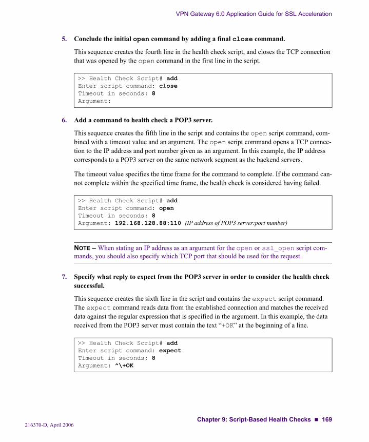
VPN Gateway 6.0 Application Guide for SSL Acceleration
5. Conclude the initial open command by adding a final close command.
This sequence creates the fourth line in the health check script, and closes the TCP connection that was opened by the open command in the first line in the script.
6. Add a command to health check a POP3 server.
This sequence creates the fifth line in the script and contains the open script command, com-bined with a timeout value and an argument. The open script command opens a TCP connec-tion to the IP address and port number given as an argument. In this example, the IP address corresponds to a POP3 server on the same network segment as the backend servers.
The timeout value specifies the time frame for the command to complete. If the command can-not complete within the specified time frame, the health check is considered having failed.
NOTE – When stating an IP address as an argument for the open or ssl_open script com-mands, you should also specify which TCP port that should be used for the request.
7. Specify what reply to expect from the POP3 server in order to consider the health check successful.
This sequence creates the sixth line in the script and contains the expect script command. The expect command reads data from the established connection and matches the received data against the regular expression that is specified in the argument. In this example, the data received from the POP3 server must contain the text “+OK” at the beginning of a line.
>> Health Check Script# addEnter script command: closeTimeout in seconds: 8Argument:
>> Health Check Script# addEnter script command: openTimeout in seconds: 8Argument: 192.168.128.88:110 (IP address of POP3 server:port number)
>> Health Check Script# addEnter script command: expectTimeout in seconds: 8Argument: ^\+OK
216370-D, April 2006Chapter 9: Script-Based Health Checks 169
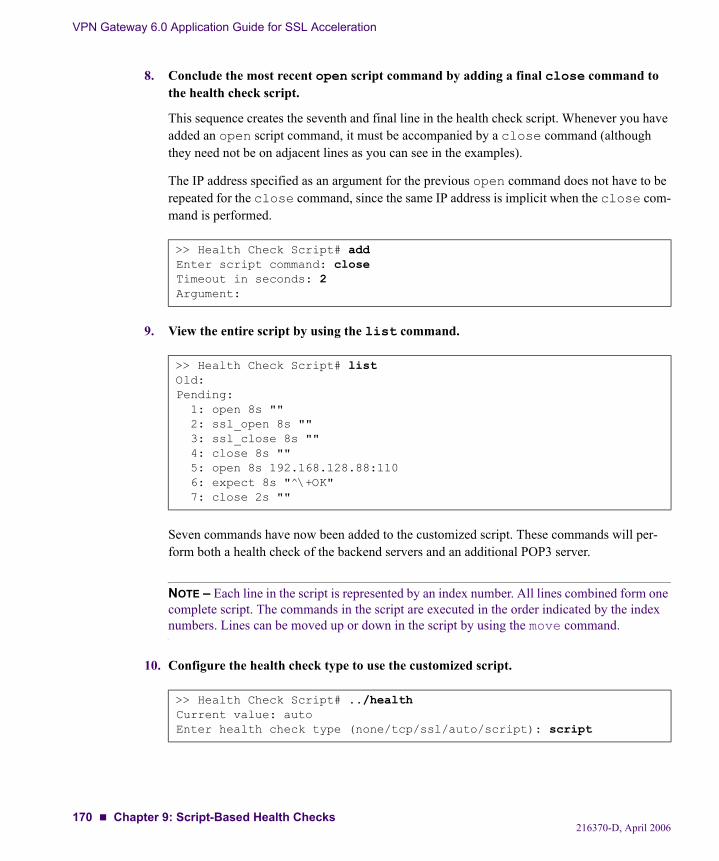
VPN Gateway 6.0 Application Guide for SSL Acceleration
8. Conclude the most recent open script command by adding a final close command to the health check script.
This sequence creates the seventh and final line in the health check script. Whenever you have added an open script command, it must be accompanied by a close command (although they need not be on adjacent lines as you can see in the examples).
The IP address specified as an argument for the previous open command does not have to be repeated for the close command, since the same IP address is implicit when the close com-mand is performed.
9. View the entire script by using the list command.
Seven commands have now been added to the customized script. These commands will per-form both a health check of the backend servers and an additional POP3 server.
NOTE – Each line in the script is represented by an index number. All lines combined form one complete script. The commands in the script are executed in the order indicated by the index numbers. Lines can be moved up or down in the script by using the move command.
10. Configure the health check type to use the customized script.
>> Health Check Script# addEnter script command: closeTimeout in seconds: 2Argument:
>> Health Check Script# listOld:Pending: 1: open 8s "" 2: ssl_open 8s "" 3: ssl_close 8s "" 4: close 8s "" 5: open 8s 192.168.128.88:110 6: expect 8s "^\+OK" 7: close 2s ""
>> Health Check Script# ../healthCurrent value: autoEnter health check type (none/tcp/ssl/auto/script): script
216370-D, April 2006170 Chapter 9: Script-Based Health Checks
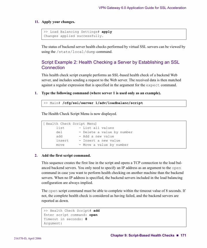
VPN Gateway 6.0 Application Guide for SSL Acceleration
11. Apply your changes.
The status of backend server health checks performed by virtual SSL servers can be viewed by using the /stats/local/dump command.
Script Example 2: Health Checking a Server by Establishing an SSL ConnectionThis health check script example performs an SSL-based health check of a backend Web server, and includes sending a request to the Web server. The received data is then matched against a regular expression that is specified in the argument for the expect command.
1. Type the following command (where server 1 is used only as an example).
The Health Check Script Menu is now displayed.
2. Add the first script command.
This sequence creates the first line in the script and opens a TCP connection to the load bal-anced backend servers. You only need to specify an IP address as an argument to the open command in case you want to perform health checking on another machine than the backend servers. When no IP address is specified, the backend servers included in the load balancing configuration are always implied.
The open script command must be able to complete within the timeout value of 8 seconds. If not, the complete health check is considered as having failed, and the backend servers are reported as down.
>> Load Balancing Settings# applyChanges applied successfully.
>> Main# /cfg/ssl/server 1/adv/loadbalanc/script
[Health Check Script Menu] list - List all values del - Delete a value by number add - Add a new value insert - Insert a new value move - Move a value by number
>> Health Check Script# addEnter script command: openTimeout in seconds: 8Argument:
216370-D, April 2006Chapter 9: Script-Based Health Checks 171
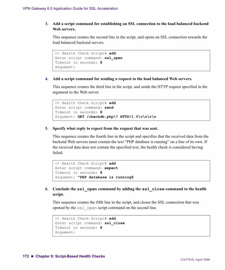
VPN Gateway 6.0 Application Guide for SSL Acceleration
3. Add a script command for establishing an SSL connection to the load balanced backend Web servers.
This sequence creates the second line in the script, and opens an SSL connection towards the load balanced backend servers.
4. Add a script command for sending a request to the load balanced Web servers.
This sequence creates the third line in the script, and sends the HTTP request specified in the argument to the Web server.
5. Specify what reply to expect from the request that was sent.
This sequence creates the fourth line in the script and specifies that the received data from the backend Web servers must contain the text “PHP database is running” on a line of its own. If the received data does not contain the specified text, the health check is considered having failed.
6. Conclude the ssl_open command by adding the ssl_close command to the health script.
This sequence creates the fifth line in the script, and closes the SSL connection that was opened by the ssl_open script command on the second line.
>> Health Check Script# addEnter script command: ssl_openTimeout in seconds: 8Argument:
>> Health Check Script# addEnter script command: sendTimeout in seconds: 8Argument: GET /checkdb.php\? HTTP/1.0\r\n\r\n
>> Health Check Script# addEnter script command: expectTimeout in seconds: 8Argument: ^PHP database is running$
>> Health Check Script# addEnter script command: ssl_closeTimeout in seconds: 8Argument:
216370-D, April 2006172 Chapter 9: Script-Based Health Checks
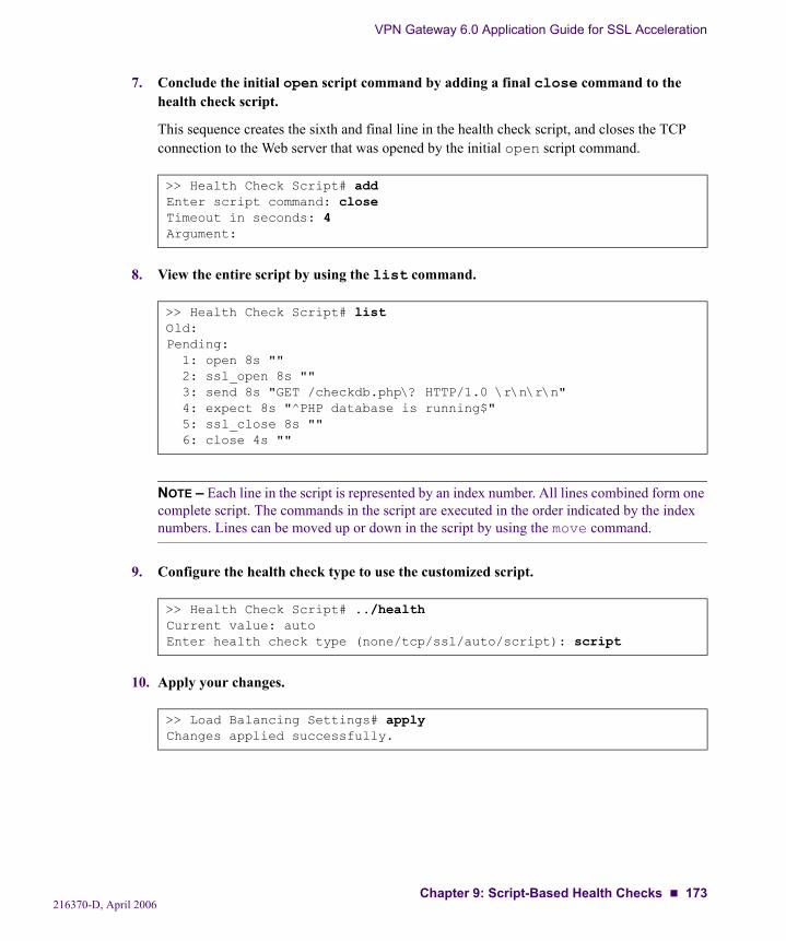
VPN Gateway 6.0 Application Guide for SSL Acceleration
7. Conclude the initial open script command by adding a final close command to the health check script.
This sequence creates the sixth and final line in the health check script, and closes the TCP connection to the Web server that was opened by the initial open script command.
8. View the entire script by using the list command.
NOTE – Each line in the script is represented by an index number. All lines combined form one complete script. The commands in the script are executed in the order indicated by the index numbers. Lines can be moved up or down in the script by using the move command.
9. Configure the health check type to use the customized script.
10. Apply your changes.
>> Health Check Script# addEnter script command: closeTimeout in seconds: 4Argument:
>> Health Check Script# listOld:Pending: 1: open 8s "" 2: ssl_open 8s "" 3: send 8s "GET /checkdb.php\? HTTP/1.0 \r\n\r\n" 4: expect 8s "^PHP database is running$" 5: ssl_close 8s "" 6: close 4s ""
>> Health Check Script# ../healthCurrent value: autoEnter health check type (none/tcp/ssl/auto/script): script
>> Load Balancing Settings# applyChanges applied successfully.
216370-D, April 2006Chapter 9: Script-Based Health Checks 173

VPN Gateway 6.0 Application Guide for SSL Acceleration
Built-In Health Check ScriptsWhen using the tcp, ssl, or auto health check options, a built-in script is used for health checking backend servers that have been configured for load balancing by using the Backend Servers menu (/cfg/ssl/server #/adv/loadbalanc/backend).
Depending on your settings for the virtual SSL server, one out of four different built-in health check scripts is selected and applied automatically. The four scripts and related virtual SSL server settings are listed below in order of complexity.
Script 1Script 1 contains the following script items:
open 8close 2
This is a basic health check script that opens a TCP connection to the backend servers, and then closes the connection. If the TCP connection cannot be opened or closed within the speci-fied time frames, the health check fails and the backend servers are reported as being down.
Script 1 is used when:
The virtual SSL server type is set to generic.
Command path in the CLI: /cfg/ssl/server #/type generic
SSL connect is disabled on the virtual SSL server.
Command path in the CLI: /cfg/ssl/server #/adv/sslconnect/dis
The health check option is set to either tcp or auto.
Command path in the CLI: /cfg/ssl/server #/adv/loadbalanc/health tcp|auto
216370-D, April 2006174 Chapter 9: Script-Based Health Checks
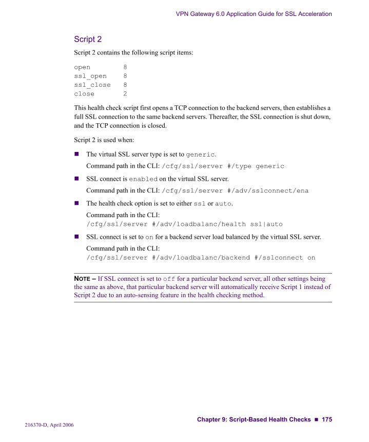
VPN Gateway 6.0 Application Guide for SSL Acceleration
Script 2Script 2 contains the following script items:
open 8ssl_open 8ssl_close 8close 2
This health check script first opens a TCP connection to the backend servers, then establishes a full SSL connection to the same backend servers. Thereafter, the SSL connection is shut down, and the TCP connection is closed.
Script 2 is used when:
The virtual SSL server type is set to generic.
Command path in the CLI: /cfg/ssl/server #/type generic
SSL connect is enabled on the virtual SSL server.
Command path in the CLI: /cfg/ssl/server #/adv/sslconnect/ena
The health check option is set to either ssl or auto.
Command path in the CLI: /cfg/ssl/server #/adv/loadbalanc/health ssl|auto
SSL connect is set to on for a backend server load balanced by the virtual SSL server.
Command path in the CLI: /cfg/ssl/server #/adv/loadbalanc/backend #/sslconnect on
NOTE – If SSL connect is set to off for a particular backend server, all other settings being the same as above, that particular backend server will automatically receive Script 1 instead of Script 2 due to an auto-sensing feature in the health checking method.
216370-D, April 2006Chapter 9: Script-Based Health Checks 175
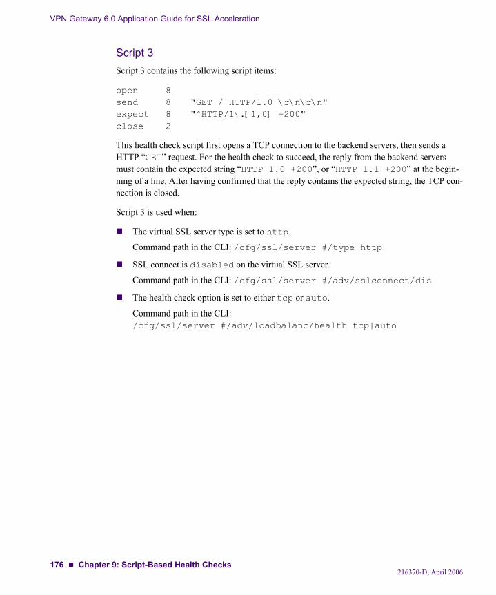
VPN Gateway 6.0 Application Guide for SSL Acceleration
Script 3Script 3 contains the following script items:
open 8send 8 "GET / HTTP/1.0 \r\n\r\n"expect 8 "^HTTP/1\.[1,0] +200"close 2
This health check script first opens a TCP connection to the backend servers, then sends a HTTP “GET” request. For the health check to succeed, the reply from the backend servers must contain the expected string “HTTP 1.0 +200”, or “HTTP 1.1 +200” at the begin-ning of a line. After having confirmed that the reply contains the expected string, the TCP con-nection is closed.
Script 3 is used when:
The virtual SSL server type is set to http.
Command path in the CLI: /cfg/ssl/server #/type http
SSL connect is disabled on the virtual SSL server.
Command path in the CLI: /cfg/ssl/server #/adv/sslconnect/dis
The health check option is set to either tcp or auto.
Command path in the CLI: /cfg/ssl/server #/adv/loadbalanc/health tcp|auto
216370-D, April 2006176 Chapter 9: Script-Based Health Checks
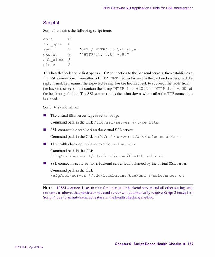
VPN Gateway 6.0 Application Guide for SSL Acceleration
Script 4Script 4 contains the following script items:
open 8ssl_open 8send 8 "GET / HTTP/1.0 \r\n\r\n"expect 8 "^HTTP/1\.[1,0] +200"ssl_close 8close 2
This health check script first opens a TCP connection to the backend servers, then establishes a full SSL connection. Thereafter, a HTTP “GET” request is sent to the backend servers, and the reply is matched against the expected string. For the health check to succeed, the reply from the backend servers must contain the string “HTTP 1.0 +200”, or “HTTP 1.1 +200” at the beginning of a line. The SSL connection is then shut down, where after the TCP connection is closed.
Script 4 is used when:
The virtual SSL server type is set to http.
Command path in the CLI: /cfg/ssl/server #/type http
SSL connect is enabled on the virtual SSL server.
Command path in the CLI: /cfg/ssl/server #/adv/sslconnect/ena
The health check option is set to either ssl or auto.
Command path in the CLI: /cfg/ssl/server #/adv/loadbalanc/health ssl|auto
SSL connect is set to on for a backend server load balanced by the virtual SSL server.
Command path in the CLI: /cfg/ssl/server #/adv/loadbalanc/backend #/sslconnect on
NOTE – If SSL connect is set to off for a particular backend server, and all other settings are the same as above, that particular backend server will automatically receive Script 3 instead of Script 4 due to an auto-sensing feature in the health checking method.
216370-D, April 2006Chapter 9: Script-Based Health Checks 177
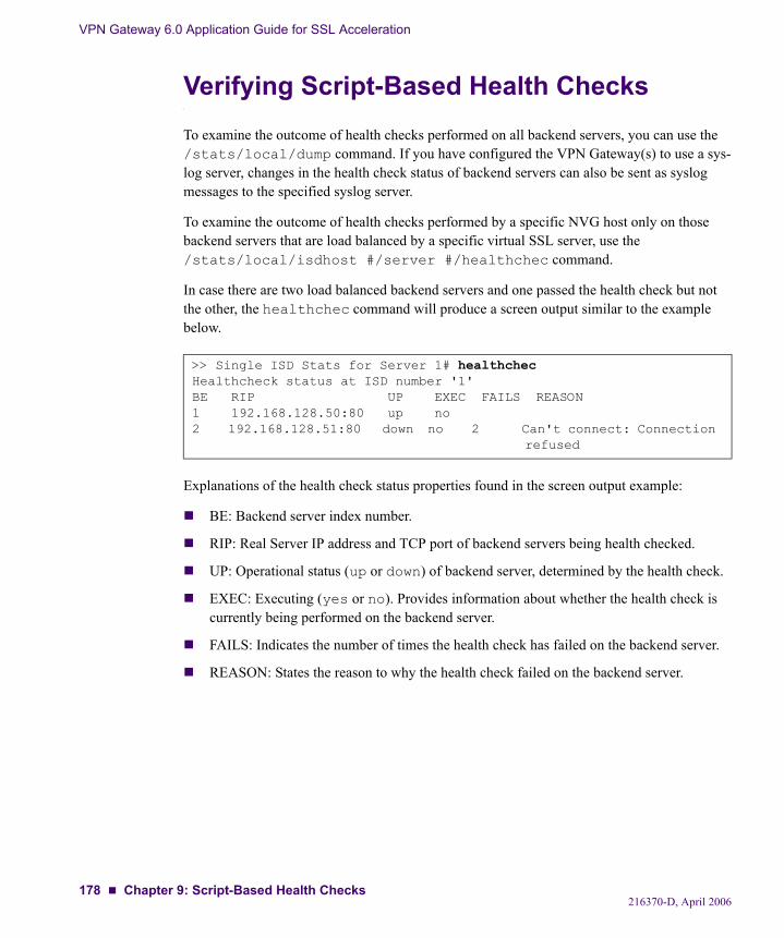
VPN Gateway 6.0 Application Guide for SSL Acceleration
Verifying Script-Based Health ChecksTo examine the outcome of health checks performed on all backend servers, you can use the /stats/local/dump command. If you have configured the VPN Gateway(s) to use a sys-log server, changes in the health check status of backend servers can also be sent as syslog messages to the specified syslog server.
To examine the outcome of health checks performed by a specific NVG host only on those backend servers that are load balanced by a specific virtual SSL server, use the /stats/local/isdhost #/server #/healthchec command.
In case there are two load balanced backend servers and one passed the health check but not the other, the healthchec command will produce a screen output similar to the example below.
Explanations of the health check status properties found in the screen output example:
BE: Backend server index number.
RIP: Real Server IP address and TCP port of backend servers being health checked.
UP: Operational status (up or down) of backend server, determined by the health check.
EXEC: Executing (yes or no). Provides information about whether the health check is currently being performed on the backend server.
FAILS: Indicates the number of times the health check has failed on the backend server.
REASON: States the reason to why the health check failed on the backend server.
>> Single ISD Stats for Server 1# healthchecHealthcheck status at ISD number '1'BE RIP UP EXEC FAILS REASON1 192.168.128.50:80 up no2 192.168.128.51:80 down no 2 Can't connect: Connection
refused
216370-D, April 2006178 Chapter 9: Script-Based Health Checks
CHAPTER 10Stand-Alone Web Server Accelerator
In the typical network setup, a Nortel VPN Gateway (NVG) requires support of a Nortel Application Switch for traffic redirection. For small, low volume sites however, it is normally not economically feasible nor necessary to have both VPN Gateways and a Nortel Application Switch. To use the VPN Gateway in scenarios without an Application Switch, you should con-figure the VPN Gateway in “stand-alone” mode.
IP Address MigrationWhen using the VPN Gateway in conjunction with a Nortel Application Switch, the Applica-tion Switch holds the virtual server IP address (VIP), and redirects traffic to the NVG cluster. In stand-alone mode, the NVG cluster will hold the VIP and perform address resolution of the VIP. In a cluster of several NVG devices, it is not possible to do this using one VIP address common to all NVGs. In stand-alone mode, the virtual SSL server will therefore be bound to several addresses specified in an address list for each virtual SSL server. The address list should contain as many IP addresses as there are VPN Gateways in the cluster. Client requests will be redirected to one of the VPN Gateways by means of round robin load balancing (see below). In other words, the SSL server address list replaces the function of the VIP used in a setup with an Application Switch. When stand-alone mode is enabled, the SSL server addresses in the list will be distributed among the VPN Gateways. If one or several VPN Gate-ways fail, the SSL server addresses currently held by these NVGs will migrate to functional NVGs. This means that as long as there is one functional VPN Gateway in the cluster, all of the SSL server addresses in the list will be available.
DNS Round Robin Load BalancingTo distribute client traffic evenly between the VPN Gateways in the cluster, you should specify as many IP addresses in the address list as there are NVGs in the cluster. In the DNS server configuration, specify that the domain name assigned to the SSL server resolves to the IP addresses configured in the IP address list. Also configure the DNS server to perform round robin load balancing and reverse DNS lookups. DNS lookups for the domain name will then resolve to the IP list addresses in a round robin manner, with the effect that client requests will be directed to the NVGs on a turn basis.
216370-D, April 2006179
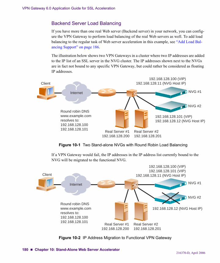
VPN Gateway 6.0 Application Guide for SSL Acceleration
Backend Server Load BalancingIf you have more than one real Web server (Backend server) in your network, you can config-ure the VPN Gateway to perform load balancing of the real Web servers as well. To add load balancing to the regular task of Web server acceleration in this example, see “Add Load Bal-ancing Support” on page 186.
The illustration below shows two VPN Gateways in a cluster where two IP addresses are added to the IP list of an SSL server in the NVG cluster. The IP addresses shown next to the NVGs are in fact not bound to any specific VPN Gateway, but could rather be considered as floating IP addresses.
Figure 10-1 Two Stand-alone NVGs with Round Robin Load Balancing
If a VPN Gateway would fail, the IP addresses in the IP address list currently bound to the NVG will be migrated to the functional NVG.
Figure 10-2 IP Address Migration to Functional VPN Gateway
Internet
Client
Round robin DNSwww.example.comresolves to:192.168.128.100192.168.128.101
Real Server #1192.168.128.200
Real Server #2192.168.128.201
192.168.128.100 (VIP)192.168.128.11 (NVG Host IP)
192.168.128.101 (VIP)192.168.128.12 (NVG Host IP)
NVG #1
NVG #2
Internet
Client
192.168.128.100 (VIP)192.168.128.101 (VIP)
192.168.128.11 (NVG Host IP)
192.168.128.12 (NVG Host IP)
Real Server #1192.168.128.200
Real Server #2192.168.128.201
NVG #1
NVG #2
Round robin DNSwww.example.comresolves to:192.168.128.100192.168.128.101
216370-D, April 2006180 Chapter 10: Stand-Alone Web Server Accelerator
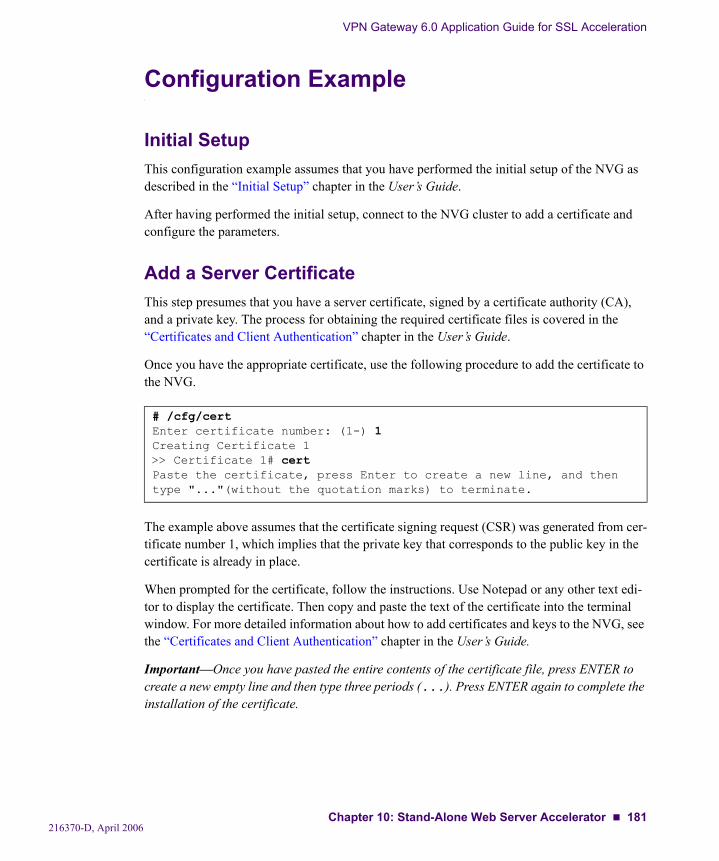
VPN Gateway 6.0 Application Guide for SSL Acceleration
Configuration Example
Initial SetupThis configuration example assumes that you have performed the initial setup of the NVG as described in the “Initial Setup” chapter in the User’s Guide.
After having performed the initial setup, connect to the NVG cluster to add a certificate and configure the parameters.
Add a Server CertificateThis step presumes that you have a server certificate, signed by a certificate authority (CA), and a private key. The process for obtaining the required certificate files is covered in the “Certificates and Client Authentication” chapter in the User’s Guide.
Once you have the appropriate certificate, use the following procedure to add the certificate to the NVG.
The example above assumes that the certificate signing request (CSR) was generated from cer-tificate number 1, which implies that the private key that corresponds to the public key in the certificate is already in place.
When prompted for the certificate, follow the instructions. Use Notepad or any other text edi-tor to display the certificate. Then copy and paste the text of the certificate into the terminal window. For more detailed information about how to add certificates and keys to the NVG, see the “Certificates and Client Authentication” chapter in the User’s Guide.
Important—Once you have pasted the entire contents of the certificate file, press ENTER to create a new empty line and then type three periods (...). Press ENTER again to complete the installation of the certificate.
# /cfg/certEnter certificate number: (1-) 1Creating Certificate 1>> Certificate 1# certPaste the certificate, press Enter to create a new line, and then type "..."(without the quotation marks) to terminate.
216370-D, April 2006Chapter 10: Stand-Alone Web Server Accelerator 181
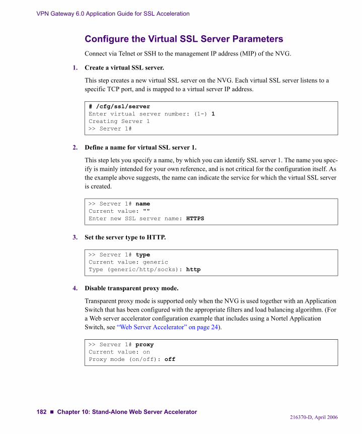
VPN Gateway 6.0 Application Guide for SSL Acceleration
Configure the Virtual SSL Server ParametersConnect via Telnet or SSH to the management IP address (MIP) of the NVG.
1. Create a virtual SSL server.
This step creates a new virtual SSL server on the NVG. Each virtual SSL server listens to a specific TCP port, and is mapped to a virtual server IP address.
2. Define a name for virtual SSL server 1.
This step lets you specify a name, by which you can identify SSL server 1. The name you spec-ify is mainly intended for your own reference, and is not critical for the configuration itself. As the example above suggests, the name can indicate the service for which the virtual SSL server is created.
3. Set the server type to HTTP.
4. Disable transparent proxy mode.
Transparent proxy mode is supported only when the NVG is used together with an Application Switch that has been configured with the appropriate filters and load balancing algorithm. (For a Web server accelerator configuration example that includes using a Nortel Application Switch, see “Web Server Accelerator” on page 24).
# /cfg/ssl/serverEnter virtual server number: (1-) 1Creating Server 1>> Server 1#
>> Server 1# nameCurrent value: ""Enter new SSL server name: HTTPS
>> Server 1# typeCurrent value: genericType (generic/http/socks): http
>> Server 1# proxyCurrent value: onProxy mode (on/off): off
216370-D, April 2006182 Chapter 10: Stand-Alone Web Server Accelerator
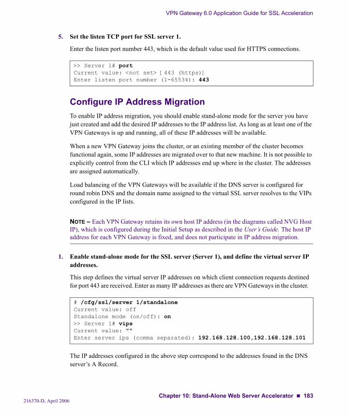
VPN Gateway 6.0 Application Guide for SSL Acceleration
5. Set the listen TCP port for SSL server 1.
Enter the listen port number 443, which is the default value used for HTTPS connections.
Configure IP Address MigrationTo enable IP address migration, you should enable stand-alone mode for the server you have just created and add the desired IP addresses to the IP address list. As long as at least one of the VPN Gateways is up and running, all of these IP addresses will be available.
When a new VPN Gateway joins the cluster, or an existing member of the cluster becomes functional again, some IP addresses are migrated over to that new machine. It is not possible to explicitly control from the CLI which IP addresses end up where in the cluster. The addresses are assigned automatically.
Load balancing of the VPN Gateways will be available if the DNS server is configured for round robin DNS and the domain name assigned to the virtual SSL server resolves to the VIPs configured in the IP lists.
NOTE – Each VPN Gateway retains its own host IP address (in the diagrams called NVG Host IP), which is configured during the Initial Setup as described in the User’s Guide. The host IP address for each VPN Gateway is fixed, and does not participate in IP address migration.
1. Enable stand-alone mode for the SSL server (Server 1), and define the virtual server IP addresses.
This step defines the virtual server IP addresses on which client connection requests destined for port 443 are received. Enter as many IP addresses as there are VPN Gateways in the cluster.
The IP addresses configured in the above step correspond to the addresses found in the DNS server’s A Record.
>> Server 1# portCurrent value: <not set> [443 (https)]Enter listen port number (1-65534): 443
# /cfg/ssl/server 1/standaloneCurrent value: offStandalone mode (on/off): on>> Server 1# vipsCurrent value: ""Enter server ips (comma separated): 192.168.128.100,192.168.128.101
216370-D, April 2006Chapter 10: Stand-Alone Web Server Accelerator 183
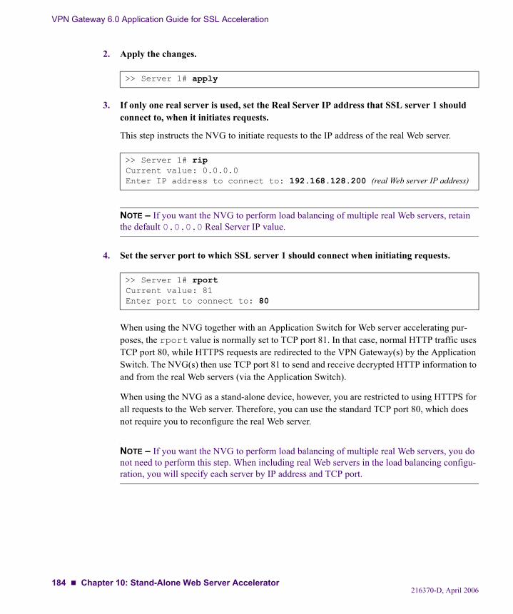
VPN Gateway 6.0 Application Guide for SSL Acceleration
2. Apply the changes.
3. If only one real server is used, set the Real Server IP address that SSL server 1 should connect to, when it initiates requests.
This step instructs the NVG to initiate requests to the IP address of the real Web server.
NOTE – If you want the NVG to perform load balancing of multiple real Web servers, retain the default 0.0.0.0 Real Server IP value.
4. Set the server port to which SSL server 1 should connect when initiating requests.
When using the NVG together with an Application Switch for Web server accelerating pur-poses, the rport value is normally set to TCP port 81. In that case, normal HTTP traffic uses TCP port 80, while HTTPS requests are redirected to the VPN Gateway(s) by the Application Switch. The NVG(s) then use TCP port 81 to send and receive decrypted HTTP information to and from the real Web servers (via the Application Switch).
When using the NVG as a stand-alone device, however, you are restricted to using HTTPS for all requests to the Web server. Therefore, you can use the standard TCP port 80, which does not require you to reconfigure the real Web server.
NOTE – If you want the NVG to perform load balancing of multiple real Web servers, you do not need to perform this step. When including real Web servers in the load balancing configu-ration, you will specify each server by IP address and TCP port.
>> Server 1# apply
>> Server 1# ripCurrent value: 0.0.0.0Enter IP address to connect to: 192.168.128.200 (real Web server IP address)
>> Server 1# rportCurrent value: 81Enter port to connect to: 80
216370-D, April 2006184 Chapter 10: Stand-Alone Web Server Accelerator
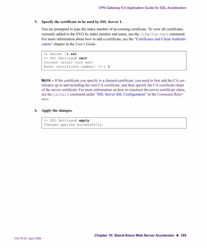
VPN Gateway 6.0 Application Guide for SSL Acceleration
5. Specify the certificate to be used by SSL Server 1.
You are prompted to type the index number of an existing certificate. To view all certificates currently added to the NVG by index number and name, use the /cfg/cur cert command. For more information about how to add a certificate, see the “Certificates and Client Authenti-cation” chapter in the User’s Guide.
NOTE – If the certificate you specify is a chained certificate, you need to first add the CA cer-tificates up to and including the root CA certificate, and then specify the CA certificate chain of the server certificate. For more information on how to construct the server certificate chain, see the cachain command under “SSL Server SSL Configuration” in the Command Refer-ence.
6. Apply the changes.
>> Server 1# ssl>> SSL Settings# certCurrent value: <not set>Enter certificate number: (1-) 1
>> SSL Settings# applyChanges applied successfully.
216370-D, April 2006Chapter 10: Stand-Alone Web Server Accelerator 185

VPN Gateway 6.0 Application Guide for SSL Acceleration
Add Load Balancing SupportIf you have more than one real (backend) Web server, you can configure the NVG to perform load balancing of the backend servers. Load balancing of backend servers requires a few addi-tional steps to complete the stand-alone Web server accelerator configuration example above.
Figure 10-3 Adding Backend Server Load Balancing to the Stand-alone Configuration
To add support for load balancing, continue from Step 6 on page 185 and follow the instruc-tions below.
1. The default value of 0.0.0.0 for the Real Server IP setting in Step 3 on page 184 should be retained.
If the current value corresponds to 0.0.0.0, press ENTER to retain the default value. If another Real Server IP address is shown, enter 0.0.0.0 and press ENTER.
>> SSL Settings# ../ripCurrent value: 0.0.0.0Enter IP address to connect to:
Internet
Client
Real Server #1192.168.128.200
192.168.128.100 (VIP)192.168.128.11 (NVG Host IP)
192.168.128.101 (VIP)192.168.128.12 (NVG Host IP)
Real Server #2192.168.128.201
NVG #1
NVG #2Round robin DNSwww.example.comresolves to:192.168.128.100192.168.128.101
216370-D, April 2006186 Chapter 10: Stand-Alone Web Server Accelerator
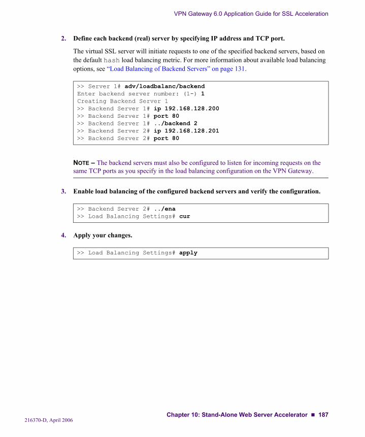
VPN Gateway 6.0 Application Guide for SSL Acceleration
2. Define each backend (real) server by specifying IP address and TCP port.
The virtual SSL server will initiate requests to one of the specified backend servers, based on the default hash load balancing metric. For more information about available load balancing options, see “Load Balancing of Backend Servers” on page 131.
NOTE – The backend servers must also be configured to listen for incoming requests on the same TCP ports as you specify in the load balancing configuration on the VPN Gateway.
3. Enable load balancing of the configured backend servers and verify the configuration.
4. Apply your changes.
>> Server 1# adv/loadbalanc/backendEnter backend server number: (1-) 1Creating Backend Server 1>> Backend Server 1# ip 192.168.128.200>> Backend Server 1# port 80>> Backend Server 1# ../backend 2>> Backend Server 2# ip 192.168.128.201>> Backend Server 2# port 80
>> Backend Server 2# ../ena>> Load Balancing Settings# cur
>> Load Balancing Settings# apply
216370-D, April 2006Chapter 10: Stand-Alone Web Server Accelerator 187

VPN Gateway 6.0 Application Guide for SSL Acceleration
Directing Traffic to Different SSL ServersTo configure several SSL servers on the NVG in stand-alone mode, e.g. to enable access to dif-ferent sites, add the required virtual server IP addresses to each SSL server’s IP list, as described earlier in this chapter. For each SSL server that you have defined, enable stand-alone mode and add the desired virtual server IP addresses to the IP list. In addition, you should con-figure the DNS server to perform round robin DNS lookups on the desired IP addresses and domain names.
Figure 10-4 Three Different SSL Servers in a Redundant Stand-alone Solution
With the setup in Figure 10-4, users can access three different virtual SSL servers, using three different domain names. If one VPN Gateway should fail, all virtual IP addresses will be migrated to the functional NVG(s), i.e. they will still be available.
Follow these steps to configure your NVG cluster as exemplified.
Configure the SSL servers you need in the NVG cluster.
Enable stand-alone mode for each configured SSL server.
Add the IP addresses (that the domain name resolves to) to the IP list of each SSL server.
Set the real server IP address of the backend server, or configure load balancing if using more than one backend server
Specify the certificate to be used by each SSL server.
For detailed instructions on how to perform the above steps, see “Configure the Virtual SSL Server Parameters” on page 182, “Configure IP Address Migration” on page 183 and “Add Load Balancing Support” on page 186.
Internet
Client
Round robin DNSwww.example.com 192.168.128.100
192.168.128.101www.example2.com 192.168.128.102
192.168.128.103www.example3.com 192.168.128.104
192.168.128.105Real Server #1
192.168.128.200Real Server #2192.168.128.201
192.168.128.100 (VIP)192.168.128.102 (VIP)192.168.128.104 (VIP)
192.168.128.11 (NVG Host IP)
192.168.128.101 (VIP)192.168.128.103 (VIP)192.168.128.105 (VIP)192.168.128.12 (NVG Host IP)
NVG #1
NVG #2
216370-D, April 2006188 Chapter 10: Stand-Alone Web Server Accelerator
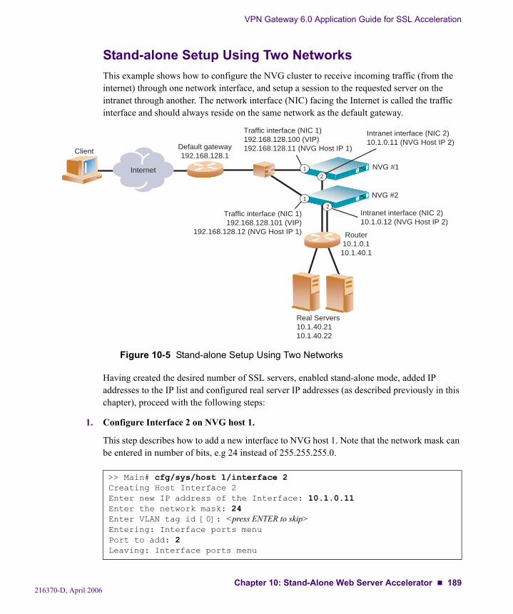
VPN Gateway 6.0 Application Guide for SSL Acceleration
Stand-alone Setup Using Two NetworksThis example shows how to configure the NVG cluster to receive incoming traffic (from the internet) through one network interface, and setup a session to the requested server on the intranet through another. The network interface (NIC) facing the Internet is called the traffic interface and should always reside on the same network as the default gateway.
Figure 10-5 Stand-alone Setup Using Two Networks
Having created the desired number of SSL servers, enabled stand-alone mode, added IP addresses to the IP list and configured real server IP addresses (as described previously in this chapter), proceed with the following steps:
1. Configure Interface 2 on NVG host 1.
This step describes how to add a new interface to NVG host 1. Note that the network mask can be entered in number of bits, e.g 24 instead of 255.255.255.0.
>> Main# cfg/sys/host 1/interface 2Creating Host Interface 2Enter new IP address of the Interface: 10.1.0.11Enter the network mask: 24Enter VLAN tag id [0]: <press ENTER to skip>Entering: Interface ports menuPort to add: 2Leaving: Interface ports menu
Internet
Client
Real Servers10.1.40.2110.1.40.22
NVG #1
NVG #2
21
12
Default gateway192.168.128.1
Traffic interface (NIC 1)192.168.128.100 (VIP)192.168.128.11 (NVG Host IP 1)
Intranet interface (NIC 2)10.1.0.11 (NVG Host IP 2)
Traffic interface (NIC 1)192.168.128.101 (VIP)
192.168.128.12 (NVG Host IP 1)
Intranet interface (NIC 2)10.1.0.12 (NVG Host IP 2)
Router10.1.0.1
10.1.40.1
216370-D, April 2006Chapter 10: Stand-Alone Web Server Accelerator 189
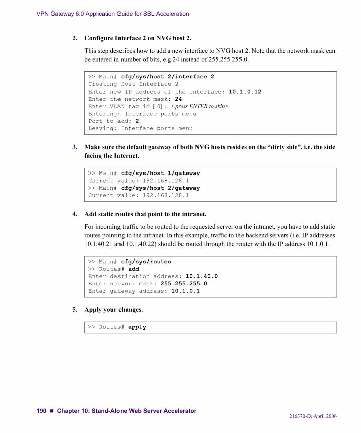
VPN Gateway 6.0 Application Guide for SSL Acceleration
2. Configure Interface 2 on NVG host 2.
This step describes how to add a new interface to NVG host 2. Note that the network mask can be entered in number of bits, e.g 24 instead of 255.255.255.0.
3. Make sure the default gateway of both NVG hosts resides on the “dirty side”, i.e. the side facing the Internet.
4. Add static routes that point to the intranet.
For incoming traffic to be routed to the requested server on the intranet, you have to add static routes pointing to the intranet. In this example, traffic to the backend servers (i.e. IP addresses 10.1.40.21 and 10.1.40.22) should be routed through the router with the IP address 10.1.0.1.
5. Apply your changes.
>> Main# cfg/sys/host 2/interface 2Creating Host Interface 2Enter new IP address of the Interface: 10.1.0.12Enter the network mask: 24Enter VLAN tag id [0]: <press ENTER to skip>Entering: Interface ports menuPort to add: 2Leaving: Interface ports menu
>> Main# cfg/sys/host 1/gatewayCurrent value: 192.168.128.1>> Main# cfg/sys/host 2/gatewayCurrent value: 192.168.128.1
>> Main# cfg/sys/routes>> Routes# addEnter destination address: 10.1.40.0Enter network mask: 255.255.255.0Enter gateway address: 10.1.0.1
>> Routes# apply
216370-D, April 2006190 Chapter 10: Stand-Alone Web Server Accelerator

CHAPTER 11Global Server Load Balancing
Global server load balancing (GSLB) allows you to balance server traffic load across multiple physical sites. The Nortel GSLB implementation takes into account an individual site’s health, response time and geographic location to smoothly integrate the resources of the dispersed server sites for complete global performance. For an introduction to GSLB, see the Web OS Application Guide version 9.0 or higher.
NOTE – The following configuration examples assume that an ordinary Nortel Application Switch is configured for GSLB on the current site.
Configuration Example
IntroductionThis configuration example is based on the following prerequisites: two sites—A and B—host the domain www.example.com. An ordinary Nortel Application Switch is configured for glo-bal server load balancing (GSLB).
There are several issues connected with GSLB and SSL that makes it impossible to rely on the switch to provide all GSLB functionality. The SSL box has to participate.
A typical situation when the issues primarily occur, is when a client has been sent to a site, say site A, by its initial DNS lookup of www.example.com. After a while, the client performs a new DNS lookup and is then sent to site B. If cookie persistence is used, the client should be sent back to site A.
The client is sent back to site A by using a HTTP redirect, traditionally to the VIP of site A. This is a redirect to https://VIP/path. If this is done for SSL, the browser will return an error, since it unsuccessfully tries to match the host part of the URL (VIP in this case) with the com-mon name in the certificate of that site (in this case; www.example.com).
216370-D, April 2006191
VPN Gateway 6.0 Application Guide for SSL Acceleration
The only option is to redirect the client to the name of site A, i.e. to https://www.exam-ple.com/path. However, since the client has already resolved www.example.com to site B, it will be sent back to site B instead of site A.
This situation is solved by setting up a secondary VIP bound to another DNS entry, www2.example.com. The VIP redirects the client to https://www2.example.com/path. Note that the secondary VIP (www2.example.com) requires another certificate, one that has www2.example.com as significant name.
Maintaining cookie persistence Cookie persistence is implemented by encoding the VIP and the RIP in the cookie. If a client arrives to a site with a cookie that contains a VIP that isn't local, it is redirected back to the remote site that has the VIP. The problem in this case, is that the session cannot be redirected back to the primary VIP of the remote site since the VIP cannot be used in the redirect. Instead, the session has to be redirected to a secondary VIP. This means that the remote site must recog-nize both its primary VIP and its secondary VIP as local when it receives a bounced session.
SetupOn site A:VIP 1, bound to www.example.com in DNS: 192.168.128.10VIP 2, bound to www1.example.com in DNS: 192.168.128.20
On site B:VIP 2, bound to www.example.com in DNS: 192.168.128.30VIP 3, bound to www2.example.com in DNS: 192.168.128.40.
This configuration example uses a local server named 192.168.128.100 on site A, and 192.168.128.200 on site B.
216370-D, April 2006192 Chapter 11: Global Server Load Balancing

VPN Gateway 6.0 Application Guide for SSL Acceleration
Configuring the Servers at site A and BNow, configure each site, A and B.
Site AStart loading the certificates for www.example.com and www1.example.com on the NVG for Site A (cert 1 and 2).
Add a Server CertificateThis step presumes a server certificate, signed by a certificate authority (CA), and a private key. The process for obtaining the required certificate files is covered in the “Certificates and Client Authentication” chapter in the User’s Guide.
Once you have the appropriate certificate, use the following procedure to add the certificate to the NVG.
The above example assumes that the certificate signing request (CSR) was generated from cer-tificate number 1, which implies that the private key that corresponds to the public key in the certificate is already in place.
When prompted for the certificate, follow the instructions. Use Notepad or any other text edi-tor to display the certificate. Then copy and paste the text of the certificate into the terminal window. For more detailed information about how to add certificates and keys to the NVG, see the “Certificates and Client Authentication” chapter in the User’s Guide.
Important—Once you have pasted the entire contents of the certificate file, press ENTER to create a new empty line and then type three periods (...). Press ENTER again to complete the installation of the certificate.
# /cfg/certEnter certificate number: (1-) 1Creating Certificate 1>> Certificate 1# certPaste the certificate, press Enter to create a new line, and then type "..."(without the quotation marks) to terminate.
216370-D, April 2006Chapter 11: Global Server Load Balancing 193
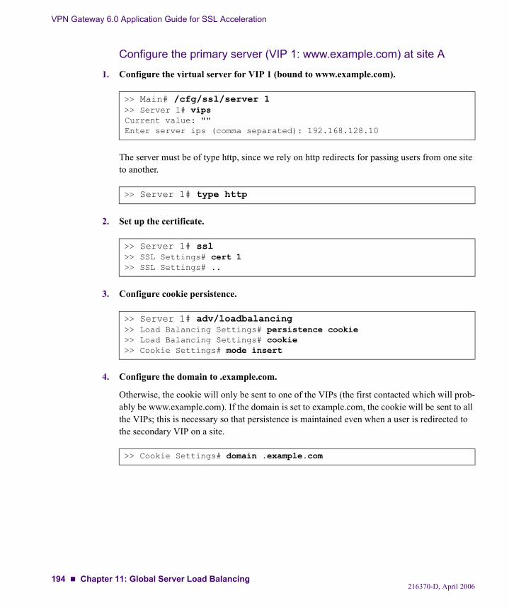
VPN Gateway 6.0 Application Guide for SSL Acceleration
Configure the primary server (VIP 1: www.example.com) at site A
1. Configure the virtual server for VIP 1 (bound to www.example.com).
The server must be of type http, since we rely on http redirects for passing users from one site to another.
2. Set up the certificate.
3. Configure cookie persistence.
4. Configure the domain to .example.com.
Otherwise, the cookie will only be sent to one of the VIPs (the first contacted which will prob-ably be www.example.com). If the domain is set to example.com, the cookie will be sent to all the VIPs; this is necessary so that persistence is maintained even when a user is redirected to the secondary VIP on a site.
>> Main# /cfg/ssl/server 1>> Server 1# vipsCurrent value: ""Enter server ips (comma separated): 192.168.128.10
>> Server 1# type http
>> Server 1# ssl>> SSL Settings# cert 1>> SSL Settings# ..
>> Server 1# adv/loadbalancing>> Load Balancing Settings# persistence cookie>> Load Balancing Settings# cookie>> Cookie Settings# mode insert
>> Cookie Settings# domain .example.com
216370-D, April 2006194 Chapter 11: Global Server Load Balancing
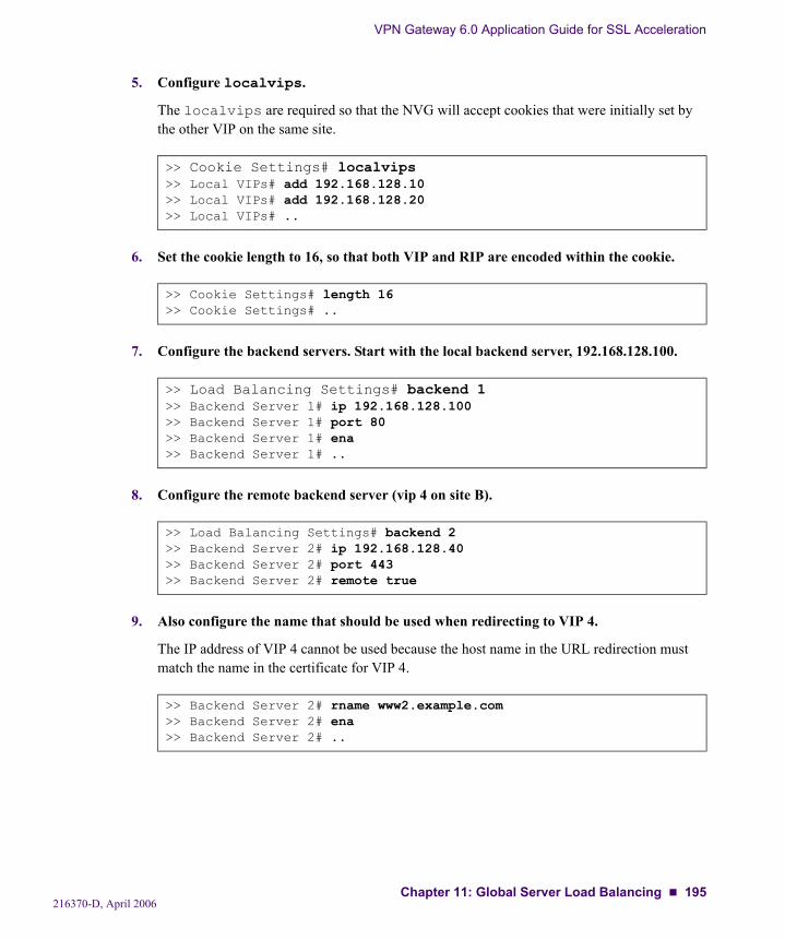
VPN Gateway 6.0 Application Guide for SSL Acceleration
5. Configure localvips.
The localvips are required so that the NVG will accept cookies that were initially set by the other VIP on the same site.
6. Set the cookie length to 16, so that both VIP and RIP are encoded within the cookie.
7. Configure the backend servers. Start with the local backend server, 192.168.128.100.
8. Configure the remote backend server (vip 4 on site B).
9. Also configure the name that should be used when redirecting to VIP 4.
The IP address of VIP 4 cannot be used because the host name in the URL redirection must match the name in the certificate for VIP 4.
>> Cookie Settings# localvips>> Local VIPs# add 192.168.128.10>> Local VIPs# add 192.168.128.20>> Local VIPs# ..
>> Cookie Settings# length 16>> Cookie Settings# ..
>> Load Balancing Settings# backend 1>> Backend Server 1# ip 192.168.128.100>> Backend Server 1# port 80>> Backend Server 1# ena>> Backend Server 1# ..
>> Load Balancing Settings# backend 2>> Backend Server 2# ip 192.168.128.40>> Backend Server 2# port 443>> Backend Server 2# remote true
>> Backend Server 2# rname www2.example.com>> Backend Server 2# ena>> Backend Server 2# ..
216370-D, April 2006Chapter 11: Global Server Load Balancing 195
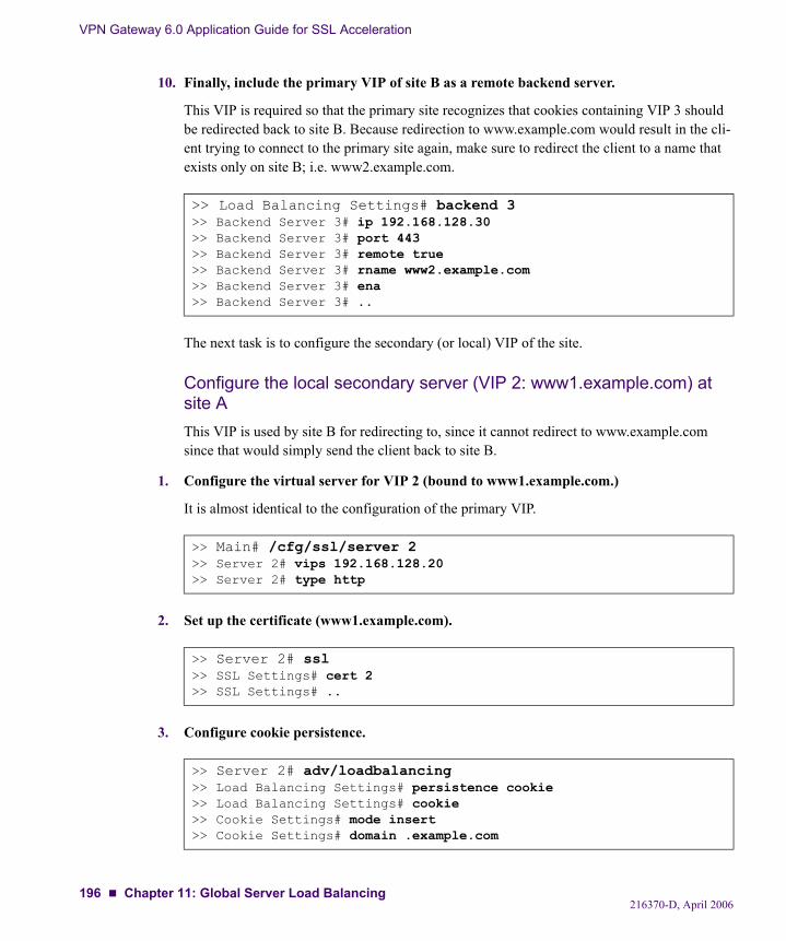
VPN Gateway 6.0 Application Guide for SSL Acceleration
10. Finally, include the primary VIP of site B as a remote backend server.
This VIP is required so that the primary site recognizes that cookies containing VIP 3 should be redirected back to site B. Because redirection to www.example.com would result in the cli-ent trying to connect to the primary site again, make sure to redirect the client to a name that exists only on site B; i.e. www2.example.com.
The next task is to configure the secondary (or local) VIP of the site.
Configure the local secondary server (VIP 2: www1.example.com) at site AThis VIP is used by site B for redirecting to, since it cannot redirect to www.example.com since that would simply send the client back to site B.
1. Configure the virtual server for VIP 2 (bound to www1.example.com.)
It is almost identical to the configuration of the primary VIP.
2. Set up the certificate (www1.example.com).
3. Configure cookie persistence.
>> Load Balancing Settings# backend 3>> Backend Server 3# ip 192.168.128.30>> Backend Server 3# port 443>> Backend Server 3# remote true>> Backend Server 3# rname www2.example.com>> Backend Server 3# ena>> Backend Server 3# ..
>> Main# /cfg/ssl/server 2>> Server 2# vips 192.168.128.20>> Server 2# type http
>> Server 2# ssl>> SSL Settings# cert 2>> SSL Settings# ..
>> Server 2# adv/loadbalancing>> Load Balancing Settings# persistence cookie>> Load Balancing Settings# cookie>> Cookie Settings# mode insert>> Cookie Settings# domain .example.com
216370-D, April 2006196 Chapter 11: Global Server Load Balancing
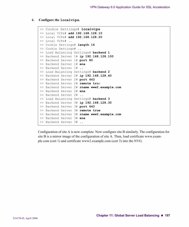
VPN Gateway 6.0 Application Guide for SSL Acceleration
4. Configure the localvips.
Configuration of site A is now complete. Now configure site B similarly. The configuration for site B is a mirror image of the configuration of site A. Then, load certificate www.exam-ple.com (cert 1) and certificate www2.example.com (cert 3) into the NVG.
>> Cookie Settings# localvips>> Local VIPs# add 192.168.128.10 >> Local VIPs# add 192.168.128.20>> Local VIPs# ..>> Cookie Settings# length 16>> Cookie Settings# ..>> Load Balancing Settings# backend 1>> Backend Server 1# ip 192.168.128.100>> Backend Server 1# port 80>> Backend Server 1# ena>> Backend Server 1# ..>> Load Balancing Settings# backend 2>> Backend Server 2# ip 192.168.128.40>> Backend Server 2# port 443>> Backend Server 2# remote true>> Backend Server 2# rname www2.example.com>> Backend Server 2# ena>> Backend Server 2# ..>> Load Balancing Settings# backend 3>> Backend Server 3# ip 192.168.128.30>> Backend Server 3# port 443>> Backend Server 3# remote true>> Backend Server 3# rname www2.example.com>> Backend Server 3# ena>> Backend Server 3# ..
216370-D, April 2006Chapter 11: Global Server Load Balancing 197
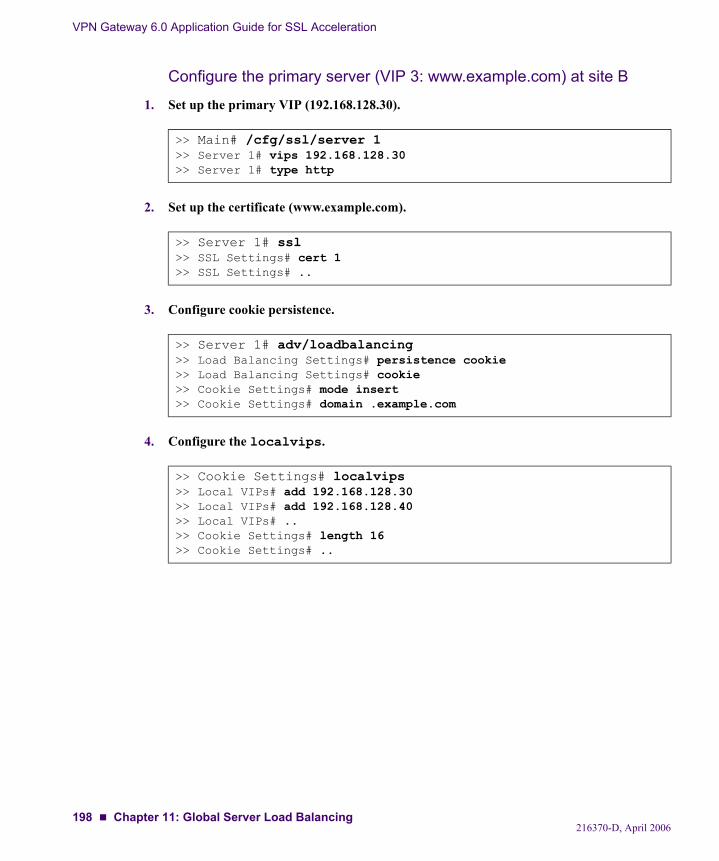
VPN Gateway 6.0 Application Guide for SSL Acceleration
Configure the primary server (VIP 3: www.example.com) at site B
1. Set up the primary VIP (192.168.128.30).
2. Set up the certificate (www.example.com).
3. Configure cookie persistence.
4. Configure the localvips.
>> Main# /cfg/ssl/server 1>> Server 1# vips 192.168.128.30>> Server 1# type http
>> Server 1# ssl>> SSL Settings# cert 1>> SSL Settings# ..
>> Server 1# adv/loadbalancing>> Load Balancing Settings# persistence cookie>> Load Balancing Settings# cookie>> Cookie Settings# mode insert>> Cookie Settings# domain .example.com
>> Cookie Settings# localvips>> Local VIPs# add 192.168.128.30 >> Local VIPs# add 192.168.128.40>> Local VIPs# ..>> Cookie Settings# length 16>> Cookie Settings# ..
216370-D, April 2006198 Chapter 11: Global Server Load Balancing

VPN Gateway 6.0 Application Guide for SSL Acceleration
5. And configure the backend servers.
Configure the local secondary server (VIP 4: www2.example.com) at site B
1. Set up the primary VIP (192.168.128.40).
2. Set up the certificate (www2.example.com).
3. Configure cookie persistence.
>> Load Balancing Settings# backend 1>> Backend Server 1# ip 192.168.128.200>> Backend Server 1# port 80>> Backend Server 1# ena>> Backend Server 1# ..>> Load Balancing Settings# backend 2>> Backend Server 2# ip 192.168.128.20>> Backend Server 2# port 443>> Backend Server 2# remote true>> Backend Server 2# rname www1.example.com>> Backend Server 2# ena>> Backend Server 2# ..>> Load Balancing Settings# backend 3>> Backend Server 3# ip 192.168.128.10>> Backend Server 3# port 443>> Backend Server 3# remote true>> Backend Server 3# rname www1.example.com>> Backend Server 3# ena>> Backend Server 3# ..
>> Main# /cfg/ssl/server 2>> Server 2# vips 192.168.128.40>> Server 2# type http
>> Server 2# ssl>> SSL Settings# cert 3>> SSL Settings# ..
>> Server 2# adv/loadbalancing>> Load Balancing Settings# persistence cookie>> Load Balancing Settings# cookie>> Cookie Settings# mode insert>> Cookie Settings# domain .example.com
216370-D, April 2006Chapter 11: Global Server Load Balancing 199

VPN Gateway 6.0 Application Guide for SSL Acceleration
4. Configure the localvips.
5. And configure the backend servers.
Test the setupYou can now test your setup by pointing your browser to https://www1.example.com and browse the site. This will cause a cookie to be generated which contains VIP2: RIP. Then, if you point the browser to https://www2.example.com, it should be redirected back to https://www1.example.com since site B will detect a cookie that contains a remote VIP.
>> Cookie Settings# localvips>> Local VIPs# add 192.168.128.30 >> Local VIPs# add 192.168.128.40>> Local VIPs# ..>> Cookie Settings# length 16>> Cookie Settings# ..
>> Load Balancing Settings# backend 1>> Backend Server 1# ip 192.168.128.200>> Backend Server 1# port 80>> Backend Server 1# ena>> Backend Server 1# ..>> Load Balancing Settings# backend 2>> Backend Server 2# ip 192.168.128.20>> Backend Server 2# port 443>> Backend Server 2# remote true>> Backend Server 2# rname www1.example.com>> Backend Server 2# ena>> Backend Server 2# ..>> Load Balancing Settings# backend 3>> Backend Server 3# ip 192.168.128.10>> Backend Server 3# port 443>> Backend Server 3# remote true>> Backend Server 3# rname www1.example.com>> Backend Server 3# ena>> Backend Server 3# ..
216370-D, April 2006200 Chapter 11: Global Server Load Balancing
Glossary
ARP Address Resolution Protocol. A network layer protocol used to convert an IP address into a physical address, such as an Ethernet address. A host wishing to obtain a physical address broadcasts an ARP request onto the TCP/IP network. The host on the network that has the IP address in the request then replies with its physical hardware address.
CA (Certificate Authority)
A trusted third-party organization or company that issues digital certificates. The role of the CA in this process is to guarantee that the entity granted the unique certificate is, in fact, who he or she claims to be.
CLI (Command Line Interface)
The text-based interface on the VPN Gateway, presented to the user after having logged in. The CLI can be accessed via a console connection or remote connection (Telnet or SSH). The CLI is used for collecting NVG information and configuring the NVG.
Cluster (of VPN Gateways)
A cluster is a group of VPN Gateways that share the same configu-ration parameters. There can be more than one NVG cluster in the network, each with its own set of parameters and services to be used with different real servers. Every cluster has a Management IP address (MIP), which is an IP alias to one of the master VPN Gate-ways in the cluster.
Console Connection A connection to a VPN Gateway established via the console port.
CRL (Certificate Revocation List)
A list containing the serial numbers of revoked client certificates. Each CA issues and maintains their own CRLs. If you generate cli-ent certificates on the VPN Gateway, you can also create your own CRL.
CSR (Certificate Signing Request)
A request for a digital certificate, sent to a CA. On the VPN Gate-way, you can generate a CSR from the command line interface by using the request command.
216370-D, April 2006201
VPN Gateway 6.0 Application Guide for SSL Acceleration
DCE (Data Communicatons Equipment)
A device that communicates with a Data Terminal Equipment (DTE) in RS-232C communications.
DER (Distinguished Encoding Rules)
A process for unambiguously converting an object specified in ASN.1 (such as an X.509 certificate, for example) into binary val-ues for storage or transmission on a network.
Digital Certificate The digital equivalent of an ID card used in conjunction with a public key encryption system. Digital certificates are issued by trusted third parties known as certificate authorities (CAs), after verifying that a public key belongs to a certain owner. The certifi-cation process varies depending on the CA and the level of certifi-cation.
Digital Signature A digital guarantee that a document has not been altered, as if it were carried in an electronically-sealed envelope. The “signature” is an encrypted digest of the text that is sent with the text message. The recipient decrypts the signature digest and also recomputes the digest from the received text. If the digests match, the message is proved intact and tamper free from the sender.A digital signature ensures that the document originated with the person signing it and that it was not tampered with after the signa-ture was applied. However, the sender could still be an imperson-ator and not the person he or she claims to be. To verify that the message was indeed sent by the person claiming to send it requires a digital certificate (digital ID) which is issued by a certification authority.
DIP (Destination IP) Address
The destination IP address of a frame.
DPort (Destination Port)
The destination port number, linking the incoming data to the cor-rect service. For example, port 80 for HTTP, port 443 for HTTPS, port 995 for POP3S.
DTE (Data Terminal Equipment)
A device that controls data flowing to or from a computer. The term is most often used in reference to serial communications defined by the RS-232C standard. This standard defines the two ends of the communication channel as being a DTE and DCE device. However, using a null-modem cable, a DTE to DTE com-munication channel can also be established between, for example, two computers.
216370-D, April 2006202 Glossary
VPN Gateway 6.0 Application Guide for SSL Acceleration
GSLB (Global Server Load Balancing)
A Nortel Application Switch feature that allows you to balance server traffic load across multiple physical sites. The Nortel GSLB implementation takes into account an individual site’s health, response time, and geographical location to smoothly integrate the resources of the dispersed server sites for complete global perfor-mance.
IP Interface IP interfaces are defined on the Nortel Application Switch and are used for defining the subnets to which the switch belongs. Up to 256 IP interfaces can be configured on an Application Switch. The IP address assigned to each IP interface provides the switch with an IP presence on your network. No two IP interfaces can be on the same IP subnet. The IP interfaces can be used for connecting to the switch for remote configuration, and for routing between subnets and VLANs (if used).
Master VPN Gateway
A VPN Gateway in a cluster that is in control of the MIP address, or can take over the control of the MIP address should another mas-ter fail. Configuration changes in the cluster are propagated to other members through the master VPN Gateways.
MIB (Management Information Base)
An SNMP structure that describes which groups and objects that can be monitored on a particular device.
MIP (Management IP) Address
An IP address that is an IP alias to a master VPN Gateway in a cluster of VPN Gateways. The MIP address identifies the cluster and is used when making configuration changes via a Telnet or SSH connection.
Nslookup A utility used to find the IP address or host name of a machine on a network. In order to use the nslookup command on the NVG, it must have been configured to use a DNS server.
NTP (Network Time Protocol)
A protocol used to synchronize the real-time clock in a computer. There are numerous primary and secondary servers on the Internet that are synchronized to the Coordinated Universal Time (UTC) via radio, satellite or modem.
NVG Nortel VPN Gateway.
Passphrase Passphrases differ from passwords only in length. Passwords are usually short, from six to ten characters. Short passwords may be adequate for logging onto computer systems that are programmed to detect a large number of incorrect guesses, but they are not safe for use with encryption systems. Passphrases are usually much longer—up to 100 characters or more. Their greater length makes passphrases more secure.
216370-D, April 2006Glossary 203

VPN Gateway 6.0 Application Guide for SSL Acceleration
PEM (Privacy Enhanced Mail)
A standard for secure e-mail on the Internet. It supports encryption, digital signatures and digital certificates as well as both private and public key methods. Keys and certificates are often stored in the PEM format.
Ping (Packet INternet Groper)
A utility used to determine whether a particular IP address is online.
PKCS #12 A standard for storing private keys and certificates.
PKI (public key infrastructure)
Short for public key infrastructure, a system of digital certificates, Certificate Authorities, and other registration authorities that verify and authenticate the validity of each party involved in an Internet transaction. PKIs are currently evolving and there is no single PKI nor even a single agreed-upon standard for setting up a PKI. How-ever, nearly everyone agrees that reliable PKIs are necessary before electronic commerce can become widespread. A PKI is also called a trust hierarchy.
Portal Applies to the VPN feature. The Portal Web page is displayed fol-lowing a successful login to a virtual SSL server configured as a portal server. The Portal contains five different tabs from where the user can access various intranet resources such as web, mail and file servers. For more information about the VPN feature, see the Application Guide for VPN.
Real Server Group A group of real servers that are associated with a virtual IP address (VIP) or filter on a Nortel Application Switch.
RIP (Real Server IP) Address
A real server IP address that the Nortel Application Switch load balances to when requests are made to a virtual IP address (VIP).
RPort (Real Server Port)
The real server port, which a virtual SSL server on the NVG uses when sending and receiving information to and from the real serv-ers.
Setup Utility When turning on a VPN Gateway the very first time, the Setup util-ity starts up automatically. The Setup utility is used for performing a basic configuration of the NVG cluster. The Setup utility first presents you with the choice of setting up the NVG as a single device, or to add the VPN Gateway to an existing cluster.If you perform a reinstallation of the NVG software, you will also enter the Setup Utility after the VPN Gateway has rebooted.
SIP (Source IP) Address
The source IP address of a frame.
216370-D, April 2006204 Glossary
VPN Gateway 6.0 Application Guide for SSL Acceleration
Slave A VPN Gateway that depends on a master VPN Gateway in the same cluster for proper configuration.
SNMP (Simple Network Management Protocol)
A network monitoring and control protocol. Data is passed from SNMP agents, which are hardware and/or software processes reporting activity in each network device (a VPN Gateway, for example), to the workstation console (or SNMP manager) used to oversee the network. The SNMP agents return information con-tained in a MIB (Management Information Base), which is a data structure that defines what information is obtainable from the device.
SOCKS A generic, proxy protocol for TCP/IP-based networking applica-tions. The SOCKS protocol provides a flexible framework for developing secure communications by easily integrating other security technologies, e.g. SSL. SOCKS includes two components, the SOCKS server and the SOCKS client. The SOCKS server is implemented at the applica-tion layer, while the SOCKS client is implemented between the application and transport layers. The basic purpose of the protocol is to enable hosts on one side of a SOCKS server to gain access to hosts on the other side of a SOCKS server, without requiring direct IP reachability.
SPort (Source Port) The source destination port, linking the incoming data to the cor-rect service. For example, port 80 for HTTP, port 443 for HTTPS, port 995 for POP3S.
SSH (Secure Shell) A program used to log into another computer over a network, exe-cute commands in a remote machine, and move files from one machine to another. SSH provides strong authentication and secure communications over insecure channels.
SSL (Secure Sockets Layer) Protocol
The SSL protocol is the leading security protocol on the Internet. It runs above the TCP/IP protocol and below higher-level protocols such as HTTP or IMAP. SSL uses TCP/IP on behalf of the higher-level protocols and, in the process, allows an SSL-enabled server to authenticate itself to an SSL-enabled client.
216370-D, April 2006Glossary 205
VPN Gateway 6.0 Application Guide for SSL Acceleration
SSL VPN Feature allowing remote access to intranet resources (such as appli-cations, mail, files, intranet web pages) via a secure connection. The underlying protocol used for these sessions is SSL.With the SSL VPN feature enabled, mobile workers, telecommut-ers and partners can access information and/or applications on the intranet, either via the SSL VPN Portal Page (browser-based mode) or by using the SSL VPN SOCKS client software (transparent mode). What information should be accessible to the user is deter-mined via access rules. For more information about the VPN fea-ture, see the Application Guide for VPN.
STP (Spanning Tree Protocol)
An algorithm used in transparent bridges that dynamically deter-mines the best path from source to destination. It avoids bridge loops (two or more paths linking one segment to another), which can cause the bridges to misinterpret results. The algorithm creates a hierarchical “tree” that “spans” the entire network including all switches. It determines all redundant paths and makes only one of them active at any given time.
TLS (Transport Layer Security)
The TLS protocol provides communications privacy over the Internet. The protocol allows client/server applications to communicate in a way that is designed to prevent eavesdropping, tampering, or message forgery.
Traceroute A utility used to identify the route used for station-to-station con-nectivity across the network.
Trap If a trap is defined in the MIB, a trap message is sent from the SNMP agent to the SNMP manager when the trap is triggered. A trap can for example define a hardware failure in a monitored device.
URI (Uniform Resource Identifier)
The addressing technology from which URLs are created. Techni-cally, URLs such as HTTP:// and FTP:// are specific subsets of URIs, although the term URL is mostly heard.
VIP (Virtual IP) Address
An IP address that the switch owns and uses to load balance partic-ular service requests (like HTTP) to other servers.
Virtual Router A shared address between two devices utilizing VRRP, as defined in RFC 2338. One virtual router is associated with an IP interface defined on the Nortel Application Switch. All IP interfaces on the Application Switches must be in a VLAN. If there is more than one VLAN defined on the Application Switch, then the VRRP broad-cast will only be sent out on the VLAN for which the associated IP interface is a member.
216370-D, April 2006206 Glossary
VPN Gateway 6.0 Application Guide for SSL Acceleration
Virtual SSL Server A virtual SSL server handles a specific service on the NVG, such as HTTPS, SMTPS, IMAPS, or POP3S. You can create up to 256 virtual SSL servers per NVG cluster, and each virtual SSL server is mapped to a virtual server on the Nortel Application Switch. In order to authenticate itself towards clients making requests for the specified service, the virtual SSL server is configured to use a digi-tal certificate.
VLAN (Virtual Local Area Network)
VLANs are commonly used to split up groups of network users into manageable broadcast domains, to create logical segmentation of workgroups, and to enforce security policies among logical seg-ments. Up to 246 VLANs are supported on a Nortel Application Switch running Web OS.
VRRP (Virtual Router Redundancy Protocol)
A protocol that acts very similarly to Cisco’s proprietary HSRP address-sharing protocol. The reason for both of these protocols is to ensure devices have a next hop or default gateway that is always available. For example, two or more devices sharing an IP interface are either advertising or listening for advertisements. These adver-tisements are sent via a broadcast message to address 224.0.0.18.With VRRP, one switch is considered the master and the other is the backup. The master is always advertising via the broadcasts. The backup switch is always listening for the broadcasts. Should the master stop advertising, the backup will take over ownership of the VRRP IP and MAC addresses as defined by the specification. The switch announces this change in ownership to the devices around it by way of a gratuitous ARP and advertisements. If the backup switch didn’t do the gratuitous ARP, the Layer 2 device attached to the switch would not know that the MAC address had moved in the network. For a more detailed description, refer to RFC 2338.
X.509 A widely-used specification for digital certificates that has been a recommendation of the ITU since 1988.
216370-D, April 2006Glossary 207

VPN Gateway 6.0 Application Guide for SSL Acceleration
216370-D, April 2006208 Glossary
Index
Symbols[ ]....................................................................... 10
Aauto health check option..................................... 135
Bbackend servers
auto health checks....................................... 135configure health checking of ........................ 134configure load balancing of .......................... 131load balancing options ................................. 131script-based health checks............................ 135SSL health checks....................................... 135TCP health checks ...................................... 135
basic operationVPN Gateway as web server accelerator .......... 18
blocking client requestmatch string configuration example............... 158
CCA, see certificate authoritycertificate authority (CA) ..................................... 15certificates
certificate authority ....................................... 15chain certificates........................................... 15register certificates ........................................ 15
chain certificatesgeneral information....................................... 15
ciphersrewrite weak cipher client request ................. 123
client requestsrewrite requests with weak cipher ................. 123
commandsconventions used in this manual...................... 10
configurationcookie-based persistence .............................. 138health checking backend servers.................... 134load balancing backend servers ..................... 131load balancing options ................................. 131persistent client connections ......................... 137rewrite weak cipher client requests ................ 123SSL-based persistence ................................. 149string load balancing options ........................ 162string matching in load balancing .......... 136, 151
content-intelligent switching ................................. 41cookie modes
insert ......................................................... 140insert, configuration example........................ 141passive....................................................... 140passive, configuration example ..................... 143rewrite ....................................................... 140rewrite, configuration example...................... 146
cookie-based persistent client connections............ 138cookies, used for persistent client connections ...... 138creating match strings for load balancing ............. 151customizing health check scripts ......................... 164
Ddigital certificates ................................................ 15digital signatures.................................................. 14documentation
other VPN Gateway manuals............................ 7dynamic data, match string configuration example 155
Eencryption
digital certificates.......................................... 15digital signatures ........................................... 14general information ....................................... 13public key encryption .................................... 14
216370-D, April 2006209
VPN Gateway 6.0 Application Guide for SSL Acceleration
end to end encryptionweb server accelerator ....................................67
extended POSIX regular expressionsin health checks...........................................166
Hhash metric, for load balancing ............................133health check methods
auto option..................................................135script-based health checks.....................135, 163SSL health checks........................................135TCP health checks .......................................135
health check scripts ............................................164available commands.....................................164built-in scripts .............................................174configuration examples ................................167extended POSIX regular expressions..............166verifying outcome........................................178
health checks, of backend servers ........................134HTTP to HTTPS redirect ....................................127
Iignore case, match string configuration option ......161insert cookie mode .............................................140
configuration example..................................141
Lleast connections metric, for load balancing ..........134load balancing
backend servers ...........................................131configuration options ...................................131creating match strings...................................151hash metric .................................................133least connections metric................................134metrics .......................................................133persistent client connections..........................137round robin metric .......................................133string load balancing options.........................162string matching............................................136string-based ................................................151
Mmail server accelerator ..........................................53manual style conventions ......................................10
match stringsblocking request, configuration example ........ 158configuration options................................... 161dynamic data, configuration example............. 155for load balancing ....................................... 151ignore case in match.................................... 161negate result in match.................................. 161static data, configuration example ................. 152
metrics, for load balancing ................................. 133
Nnegate result, match string configuration option.... 161
Ppassive cookie mode .......................................... 140
configuration example ................................. 143persistent client connections ............................... 137
cookie-based .............................................. 138SSL-based.................................................. 149
public key encryption........................................... 14public key infrastructure....................................... 13
Rredirect HTTP to HTTPS.................................... 127redundant active-standby configuration ................. 42redundant active-standby configuration with port
failover........................................................ 48register certificates............................................... 15rewrite
cookie mode............................................... 146cookie mode, configuration example ............. 146weak cipher client requests........................... 123
rewrite cookie mode .......................................... 140round robin DNS ............................................... 179round robin metric, for load balancing ................. 133
Ssample applications
content-intelligent switching........................... 41end to end encryption .................................... 67mail server accelerator ................................... 53redundant active-standby configuration............ 42redundant active-standby configuration with port
failover................................................. 48stand-alone web server accelerator ................ 179web server accelerator ................................... 24
210 Index216370-D, April 2006

VPN Gateway 6.0 Application Guide for SSL Acceleration
script commands, in health checks ...................... 164script health check option................................... 135script-based health checks
built-in ...................................................... 174general information..................................... 163verifying outcome....................................... 178
SSLexample of transaction................................... 16health checks of backend servers .................. 135public key infrastructure ................................ 13session-based persistent client connections..... 149
stand-alone web server accelerator ...................... 179directing traffic to different SSL servers......... 188with load balancing of backend servers.......... 186with multiple networks ................................ 189
static datamatch string configuration example............... 152
string matching in load balancing................ 136, 151string-based load balancing
additional options ....................................... 162string-based load balancing and blocking............. 151
TTCP health checks of backend servers ................. 135text conventions .................................................. 10typographic conventions in this manual ................. 10
Wweb server accelerator.......................................... 24
stand-alone ................................................ 179with end to end encryption ............................. 67
Index 211216370-D, April 2006

VPN Gateway 6.0 Application Guide for SSL Acceleration
h
212 Index216370-D, April 2006