VIBRATION ISOLATOR - Tozen Industrial Co.,Ltd. · 2020-04-29 · 3 VI-0120 PTM-A, A2, A3...
22
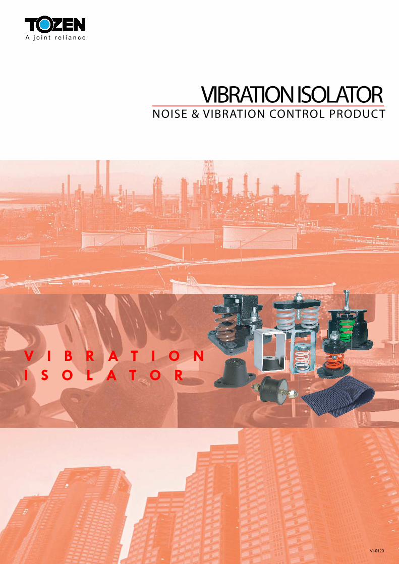
VIBRATION ISOLATOR NOISE & VIBRATION CONTROL PRODUCT A joint reliance V I B R A T I O N I S O L A T O R VI-0120
Transcript of VIBRATION ISOLATOR - Tozen Industrial Co.,Ltd. · 2020-04-29 · 3 VI-0120 PTM-A, A2, A3...
VIBRATION ISOLATORNOISE & VIBRATION CONTROL PRODUC T
A j o i n t r e l i a n c e
V I B R A T I O N
I S O L A T O R
VI-0120

VI-0120
VIBRATION TRANSMISSIBILITY CURVE
FOR AN ISOLATED SYSTEM
Today, most of sophisticated buildings are provided with
air conditioning systems and other equipments to create a
comfortable working or living environment. However,
these mechanical equipments generate vibration and
vibration induced noise, which has became a major
sources of occupant complaint in modern buildings. The
noise and vibration problem is compounded by increasing
uses of lighter weight construction and equipments located
in penthouses or intermediate level mechanical rooms. It
increased structure borne vibration and noise
transmission. Not only is the physical vibration in the
structure disturbing, but noise which is regenerated by the
structural movement may also be heard in other remote
sections of the building structure.
TOZEN vibration and noise control products are designed
to isolate or reduce the damaging structure vibration and
annoying noise produced by the mechanical equipments.
Owing to continuous research and development program,
Tozen vibration and noise control products are recognized
as a best solution to every day problems and for complex
applications requiring optimum vibration and noise
control.
Effectiveness of the vibration control, or vibration isolating
efficiency is a function of the ratio of the equipment
operating frequency, fd, to isolator natural frequency, fn.
Figure 1 shown a typical vibration transmissibility curve for
vibrating equipments supported on isolators. When the
fd=fn, the system resonance occurs, the exciting forces
will be amplified rather than reduced. As isolator natural
0.1
0.2
0.3
0.4
0.5
0.6
0.7
0.8
0.9
1.0
2.0
3.0
4.0
5.0
TR
AN
SM
ISS
IBIL
ITY
(T)
ISO
LA
TIO
N E
FF
ICIE
NC
Y (
%)
NO
IS
OLA
TIO
N
90
80
70
60
50
40
30
20
10
0
1 5
0.01 1 4
1 3
1 2
1 2 2 1 1 1
3 1
4 1
5 1
6 1
7 1
8 1
RESONANCE
T = 1 1-(fd/fn)2
% EFFICIENCY=100(1-T)
Equipment Operating Speed (fd)
Isolator Natural Frequency (fn)
( Fig. 1 )
frequency, fn, becomes lower than distributing frequency,
fd, the isolation range is entered when the ratio of fd/fn
becomes bigger than 2 .
In Figure 2, the formula expressed the natural frequency
of the isolator is a function of isolator deflection.
Theoretically, it is desirable to select isolators with a
natural frequency as far below the equipment operating
speed as possible to achieve the highest degree of
vibration control. However, when the ratio approaches
6:1, it takes very large increases in static deflection to
reduce isolator natural frequency and further reduce
transmission.
fn = 947 1
deflection in mm.
( Fig. 2 )
Theoretical isolation efficiency shown on the
transmissibility curve (Fig. 1) assumes the isolators are
located on a rigid floor. This rigidity seldom occurs in
above grade applications. In practice, considerable
building deflection can occur, which may reduce the
effectiveness of the vibration isolators. Vibration isolators
must be selected to compensate for the floor deflection.
Longer spans also allow the structure to be more flexible,
permitting the building to be more easily set in operating
speeds, equipment horsepower, damping and other
factors have been taken into consideration.
By specifying Tozen vibration isolator by type and
deflection rather than isolation efficiency, transmissibility,
or other theoretical parameters. The consulting engineer
can compensate for floor deflection and building
resonances by selecting isolators which are satisfactory to
provide minimum vibration transmission and which have
more deflection than the supporting floor.
When the specifier permits equipment suppliers to provide
"appropriate" isolators, which are not manufactured under
Tozen or equivalent high standards, a satisfactory job is
not ensured, since different brands of isolators may be
furnished and no one supplier except Tozen can carry the
full responsibility for a building free of vibration and noise
as specified.
To apply the information from the Selection Guide, base
type, isolator type, and minimum deflection, columns are
added to the equipment schedule, and the isolator
specifications are incorporated into mechanical
specifications for the project. Then, for each piece of
mechanical equipment, base type, isolator type and
minimum deflection are entered, as tabulated in the
Selection Guide.
1

VI-0120
EQ
UIP
ME
NT
TY
PE
G
RA
DE
SU
PP
OR
TE
D S
LA
B
Cate
go
ry &
Cap
acit
y
Base
T
yp
e
Iso
lato
r T
yp
e
Refr
igera
tio
n M
ach
ines
- R
ecip
rocating C
hill
ers
A
2
6
- C
entr
ifugal C
hille
rsA
1
6
- O
pen C
en
trifugal C
hille
rsC
1
6
- A
bsorp
tion C
hille
rsA
1
6
Air
co
mp
res
so
rs
- Tank M
oun
ted
A
3
20
- B
ase M
oun
ted
C
3
20
Pu
mp
s-C
los
e c
ou
ple
d
- U
p to 6
kW
B/C
2
6
- 7.5
kW
& o
ver
·F
lexi
ble
couple
d
- U
p to 3
0 k
WC
3
20
- 37 to 9
3 k
WC
3
20
- 110 k
W &
ove
rC
3
20
Co
olin
g T
ow
ers
- U
p to 3
00 r
pm
A
1,
2
6
- 301 to 5
00 r
pm
A
1,
2
6
- 501 r
pm
& o
ver
A
1,
2
6
Ax
ial, T
ub
ula
r &
Fan
head
s
- U
p to 5
50
mm
dia
.A
/B
2
6
·600m
m w
hee
l dia
. &
ove
r
- U
p to 3
00 r
pm
B/C
3
65
- 301 to 5
00 r
pm
B/C
3
20
- 501 r
pm
& o
ver
B/C
3
20
Cen
trifu
ga
l F
an
s &
Ven
t S
ets
- U
p to 5
50
mm
whee
l dia
.A
/B
2
6
·600m
m w
hee
l dia
. &
ove
r
- U
p to 3
7 k
W
-U
p to 3
00 r
pm
B
3
65
-301 to 5
00 r
pm
B
3
40
-501 r
pm
& o
ver
B
3
20
- 45 k
W &
up
-U
p to 3
00 r
pm
B/C
3
65
-301 to 5
00 r
pm
B/C
3
20
-501 r
pm
& o
ver
B/C
3
20
Packag
ed
Air
Han
dlin
g E
qu
ipm
en
ts
- U
p to 7
.5 k
WA
2
6
·11 k
W &
ove
r
- U
p to 5
00 r
pm
A
2
6
- 501 r
pm
& o
ver
A
2
6
6 M
ET
ER
FL
OO
R S
PA
N
9 M
ET
ER
FL
OO
R S
PA
N
Base
T
yp
e
Iso
lato
r T
yp
e
Min
. D
efl
ecti
on
B
ase
T
yp
e
Iso
lato
r T
yp
e
Min
. efle
cti
on
A
4
20
A
4
40
A
4
20
A
4
40
C
4
20
C
4
40
A
4
20
A
4
40
A
3
20
A
3
40
C
3
20
C
3
40
C
3
20
C
3
20
C
3
20
C
3
40
C
3
20
C
3
40
C
3
20
C
3
40
A
4
65
A
4
90
A
4
65
A
4
65
A
4
20
A
4
40
A/B
3
20
A
/B
3
20
C
3
90
C
3
90
C
3
40
C
3
65
C
3
40
C
3
40
A/B
3
20
A
/B
3
20
B
3
90
B
3
90
B
3
40
B
3
40
B
3
20
B
3
20
C
3
90
C
3
90
C
3
40
C
3
65
C
3
40
C
3
40
A
3
20
A
3
20
A
3
20
A
3
40
A
3
20
A
3
40
12 M
ET
ER
FL
OO
R S
PA
N
15 M
ET
ER
FL
OO
R S
PA
N
Base
T
yp
e
Iso
lato
r T
yp
e
B
ase
T
yp
e
Iso
lato
r T
yp
e
A
4
65
A
4
65
A
4
65
A
4
65
C
4
65
C
4
65
A
4
65
A
4
65
A
3
65
A
3
65
C
3
40
C
3
65
C
3
20
C
3
20
C
3
40
C
3
40
C
3
65
C
3
65
C
3
65
C
3
90
A
4
90
A
4
90
A
4
65
A
4
90
A
4
40
A
4
65
A/C
3
20
A
/C
3
40
C
3
90
C
3
90
C
3
65
C
3
65
C
3
40
C
3
65
A/C
3
20
A
/C
3
20
B
3
90
B
3
90
B
3
65
B
3
65
B
3
40
B
3
65
C
3
90
C
3
90
C
3
65
C
3
90
C
3
90
C
3
90
A
3
20
A
3
40
A
3
40
A
3
65
A
3
40
A
3
65
Iso
lato
r Typ
es :
1
= R
ubber
pad
3 =
Unhoused flo
or
isola
tor
or
hanger
2 =
Rubber
floor
isola
tor
and h
anger
4 =
Restr
ain
ed s
pring isola
tor
Base T
yp
es :
A
= N
o b
ase, is
ola
tors
attached d
irectly to e
quip
ment
B =
Str
uctu
ral ste
el ra
ils o
r base
C =
Concre
te inert
ia b
ase
Sele
cti
on
Gu
ide f
or
To
zen
Vib
rati
on
Iso
lato
r
2
D
Min
.D
efl
ecti
on
Min
.D
efl
ecti
on
Min
.D
efl
ecti
on
VI-01203
PTM-A, A2, A3
PTM-AM-xxx2M, PTM -AM2-xxx2M
PTM-AM-xxx4M, PTM -AM2-xxx4M
PTM-AMS3
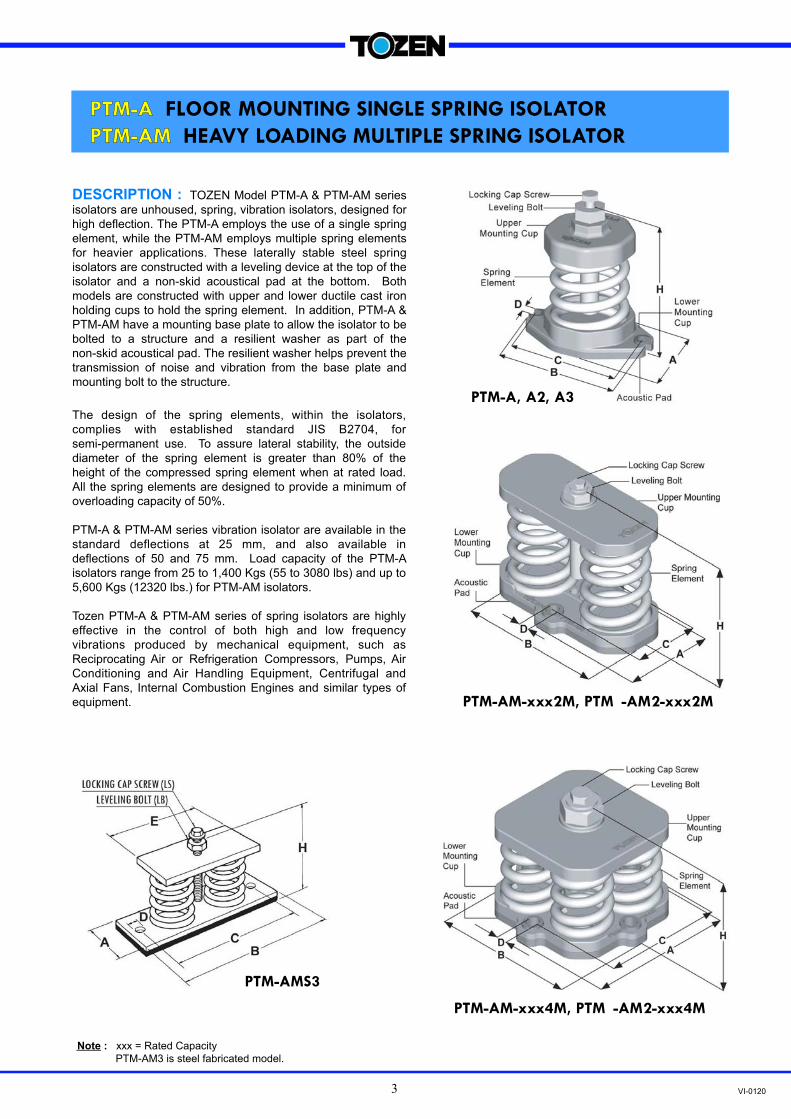
Note : xxx = Rated Capacity
PTM-AM3 is steel fabricated model.
DESCRIPTION : TOZEN Model PTM-A & PTM-AM series
isolators are unhoused, spring, vibration isolators, designed for
high deflection. The PTM-A employs the use of a single spring
element, while the PTM-AM employs multiple spring elements
for heavier applications. These laterally stable steel spring
isolators are constructed with a leveling device at the top of the
isolator and a non-skid acoustical pad at the bottom. Both
models are constructed with upper and lower ductile cast iron
holding cups to hold the spring element. In addition, PTM-A &
PTM-AM have a mounting base plate to allow the isolator to be
bolted to a structure and a resilient washer as part of the
non-skid acoustical pad. The resilient washer helps prevent the
transmission of noise and vibration from the base plate and
mounting bolt to the structure.
The design of the spring elements, within the isolators,
complies with established standard JIS B2704, for
semi-permanent use. To assure lateral stability, the outside
diameter of the spring element is greater than 80% of the
height of the compressed spring element when at rated load.
All the spring elements are designed to provide a minimum of
overloading capacity of 50%.
PTM-A & PTM-AM series vibration isolator are available in the
standard deflections at 25 mm, and also available in
deflections of 50 and 75 mm. Load capacity of the PTM-A
isolators range from 25 to 1,400 Kgs (55 to 3080 lbs) and up to
5,600 Kgs (12320 lbs.) for PTM-AM isolators.
Tozen PTM-A & PTM-AM series of spring isolators are highly
effective in the control of both high and low frequency
vibrations produced by mechanical equipment, such as
Reciprocating Air or Refrigeration Compressors, Pumps, Air
Conditioning and Air Handling Equipment, Centrifugal and
Axial Fans, Internal Combustion Engines and similar types of
equipment.
PTM-A FLOOR MOUNTING SINGLE SPRING ISOLATOR
PTM-AM HEAVY LOADING MULTIPLE SPRING ISOLATOR

VI-0120
MODEL
RATED CAPACITY SPRING
CONSTANT (kg/mm)
SPRING ELEMENT OPERATING
HEIGHT (H)
DIMENSION (mm) LOCKINGCAP
SCREW (LS)
LEVELING BOLT (LB) (kgs) (Lbs)
SPRING COLOR
OD (mm)
FREE HEIGHT
(mm) A B C D
PTM-A-25S 25 55 1.0 WHITE
50 80 120 61 107 89 10 M10x32 M16x70
PTM-A-35S 35 77 1.4 YELLOW
PTM-A-50S 50 110 2.0 ORANGE
PTM-A-80S 80 176 3.2 VIOLET
PTM-A-120S 120 264 4.8 RED
PTM-A-175S 175 385 7.0 GREY
PTM-A-225S 225 495 9.0 BROWN
PTM-A-200 200 440 8.0 VIOLET
75 100 150 88 136 117 13 M12x43
PTM-A-300 300 660 12.0 RED
PTM-A-450 450 990 18.0 GREEN
PTM-A-600 600 1320 24.0 GREY
PTM-A-825 825 1815 33.0 BROWN
PTM-A-1100 1100 2420 44.0 BLUE
PTM-A-1400 1400 3080 56.0 BLUE+BROWN
PTM-AM-1652 1650 3630 66.0 BROWN
75 100 144 112 198 75 14x18 M12x43 M22x80 PTM-AM-2202 2200 4840 88.0 BLUE
PTM-AM-2802 2800 6160 112.0 BLUE+BROWN
PTM-AM-3304 3300 7260 132.0 BROWN
75 100 152 197 197 161 14x18 M16x45 M30x90 PTM-AM-4404 4400 9680 176.0 BLUE
PTM-AM-5604 5600 12320 224.0 BLUE+BROWN
M22x80
APPLICATION : PTM-A & PTM-AM series spring isolators are recommended for use in isolating floor mounted sources
of noise and vibration located near critical quiet areas.
PTM-A series spring isolators are typically used to reduce the transmission of noise and vibration from low speed
mechanical equipment into a building structure.
PTM-A & AM series spring isolators can be used in a wide range of applications involving the isolation of mechanical
equipment, such as Reciprocating Air or Refrigeration Compressors, Close Coupled and Base Mounted Pumps, Package Air
Handling and Refrigeration Equipment, Centrifugal Fans, Internal Combustion Engines and similar equipment.
SPECIFICATION :The vibration isolators shall be free standing, with laterally stable steel spring elements, without housings, snubbers or
guides. The isolators shall be constructed with the ductile cast iron upper mounting cup and the ductile cast iron lower
mounting cup to hold the spring element, and a non-skid acoustical pad is attached under the lower cup. The isolators shall
be provided with an adjusting bolt, cap screw and washer in top of the isolator for leveling and attachment to the equipment.
The spring elements of the isolator shall have an outside diameter greater than 80% of the height of the compressed spring
element at rated load. All spring elements shall be designed to provide a minimum overloading capacity of 50%.
The isolators shall be selected to provide operating static deflection shown on the Vibration Isolation Schedule or as
indicated by the project specifications. Isolators shall be color coded or otherwise identified to indicate load capacity.
PTM-A, AM TYPE25 mm DEFLECTION SINGLE & MULTIPLE SPRING VIBRATION ISOLATOR
NOTE-1: All springs are laterally stable and suitable for free standing application. (Outside diameter > 80% of defection height)
NOTE-2: All springs are designed with additional travel to solid at least 50% of rated load.
NOTE-3: Please refer to relevant brochure or our technical division for greater deflection and loading.
4

VI-01205
MODEL
RATED CAPACITY SPRING
CONSTANT (kg/mm)
SPRING ELEMENT OPERAT-ING
HEIGHT (H)
DIMENSION (mm) LOCKING CAP
SCREW (LS)
LEVELING BOLT (LB) (kgs) (Lbs)
SPRING COLOR
OD (mm)
FREE HEIGHT
(mm) A B C D
PTM-A2-25S 25 55 0.5 WHITE
75 120 170 88 136 117 13 M12x43 M22x80
PTM-A2-35S 35 77 0.7 YELLOW
PTM-A2-50S 50 110 1.0 ORANGE
PTM-A2-80S 80 176 1.6 VIOLET
PTM-A2-125S 125 275 2.5 RED
PTM-A2-175S 175 385 3.5 GREY
PTM-A2-250S 250 550 5.0 BROWN
PTM-A2-175 175 385 3.5 ORANGE
90 145 195 101 155 130 13 M12x43 M22x115
PTM-A2-245 245 539 4.9 VIOLET
PTM-A2-350 350 770 7.0 RED
PTM-A2-525 525 1155 10.5 GREEN
PTM-A2-750 750 1650 15.0 GREY
PTM-A2-1050 1050 2310 21.0 GREY+BROWN
PTM-AM2-1502 1500 3300 30.0 GREY
90 145
189 130 230 92 14x18 M12x43 M22x80
PTM-AM2-2102 2100 4620 42.0 GREY+BROWN
PTM-AM2-3004 3000 6600 60.0 GREY 196 244 244 203 14x18 M16x45
PTM-AM2-4204 4200 9240 84.0 GREY+BROWN M30x90
MODEL
RATED CAPACITY SPRING
CONSTANT (kg/mm)
SPRING ELEMENT OPERAT-ING
HEIGHT (H)
DIMENSION (mm) LOCKING CAP
SCREW (LS)
LEVELING BOLT (LB) (kgs) (Lbs)
SPRING COLOR
OD (mm)
FREE HEIGHT
(mm) A B C D
PTM-A3-180S 180 396 2.4 ORANGE
90 170 220 101 155 130 13 M12x43 M22x115 PTM-A3-255S 255 561 3.4 VIOLET
PTM-A3-375S 375 825 5.0 RED
PTM-A3-555 555 1221 7.4 GREY
110 190 242 121 181 149 13 M12x43 M22x115 PTM-A3-810 810 1782 10.8 YELLOW
PTM-A3-1065 1065 2343 14.2 YELLOW+BROWN
PTM-AMS3-1112 1110 2442 14.8 GREY
110 190 255 125 360 330 16 M12x43 M22x160 PTM-AMS3-1622- 1620 3564 21.6 YELLOW
PTM-AMS3-2132- 2130 4686 28.4 YELLOW+BROWN
PTM-A2, AM2 TYPE 50 mm DEFLECTION SINGLE & MULTIPLE SPRING VIBRATION ISOLATOR
PTM-A3, AMS3 TYPE75 mm DEFLECTION SINGLE & MULTIPLE SPRING VIBRATION ISOLATOR
NOTE-1: All springs are laterally stable and suitable for free standing application. (Outside diameter > 80% of defection height)
NOTE-2: All springs are designed with additional travel to solid at least 50% of rated load.
NOTE-3: Please refer to relevant brochure or our technical division for greater deflection and loading.
NOTE-1: All springs are laterally stable and suitable for free standing application. (Outside diameter > 80% of defection height)
NOTE-2: All springs are designed with additional travel to solid at least 50% of rated load.
NOTE-3: Please refer to relevant brochure or our technical division for greater deflection and loading
NOTE-4: PTM-AMS is multi spring of carbon steel type

VI-01206
DO NOT install the equipment on the support of a free spring. This will cause an insufficient operating height for the
spring isolator when the installation is completed.
Weight of vertical piping and valves must to supported by the suspension hangers or supports.
Install the flexible joint at the end of the installation, following the pre-extension instruction which may specified or
suggested by the flexible joint manufacturer.
Bolting down the isolator to the floor, in most cases, is not necessary as the non-slip rubber pad or mounting cup will
prevent movement. Where bolting is required, avoid a direct metal contact between bolt and mounting, to prevent
transmission of noise; the bolt shank shall be clear in the hole and a rubber washer used under the bolt head. Bolts shall
only be tightened a half turn more than hand tight.
INSTALLATION INSTRUCTION :
Block or lift up the equipment to a level so that the equipment’s leg or base is 5 mm higher than isolator’s operating
height (see catalogue). If common base & height saving isolator bracket is used, keep 50-mm clearance between the
base and floor. Maintain this height until piping installation is completed.
Locate the spring isolator under the hole in equipment’s leg or isolator’s bracket. Connect locking cap screw and washer,
but do not tighten.
Transfer the equipment weight to the spring by taking two counter-clockwise turns on each leveling bolt around the unit
until springs are compressed just enough to remove the blocks.
Tighten the locking cap screw to lock the assembly.
1)
2)
3)
4)
REMARKS :
a)
b)
c)
d)

VI-01207
PTM-C, CH, CG HOUSED SPRING ISOLATOR
DESCRIPTION : TOZEN PTM-C, PTM-CH and PTM-CG series spring vibration isolators are designed and constructed
for high deflection, with laterally stable spring elements and assembled into telescoping cast iron housing. Each cast iron
housing is equipped with an 8 mm thick, ribbed, noise absorbing pad that is bonded to the bottom. Each isolator has an
internal or external adjusting/leveling bolt as a part of the top assembly. The ribbed, noise absorbing pad has an integrated
resilient washer that prevents the transmission of noise and vibration from the contact of the bolt and mounting base plate to
the structure. Holes or slots are provided in all of the isolators for bolting the isolator to the structure. Model PTM-C series
spring isolators are available in standard deflection of 25 and 50 mm with load capacity from 200 Kgs to 1,400 Kgs (440 to
3080 lbs). Tozen Model PTM-C spring isolators are typically used to isolate vibration produced by mechanical, industrial, or
process machinery, where more damping is required and less motion can be tolerated than with free standing spring
isolators.
PTM-C, PTM-C2
APPLICATION : TOZEN Model PTM-C spring isolators are
used to isolate high and low frequency vibration generated by
floor mounted mechanical equipment located in non-critical and
semi-critical areas.
Model PTM-C spring isolators are typically used to isolate the
vibration produced by light weight mechanical equipment having
the lowest operating speed of 1,200 rpm, located on grade
supported slabs, or short structural floor spans, or when the
isolator to equipment connection is such that a leveling bolt can
be extended above the mount and act as a leveling and
attachment bolt for the supporting equipment.
Model PTM-CH isolators are available with tapped holes at the
top of the loading plate for bolting the isolator to the supporting
equipment. An internal leveling device is provided for height
adjustments, which is accessible through the side opening by
means of an open-end wrench.
Model PTM-CG isolators are available with non-skid rubber pad
bonded at the top loading plate to eliminate the need for bolting
down the supporting equipment. An internal leveling device is
provided for height adjustment, which is accessible through the
side opening by means of an open-end wrench.
PTM-C (2M)
PTM-CH (2M)
PTM-CH, PTM-CH2
PTM-CG, PTM-CG2 PTM-CG(2M)
VI-0120
MODEL
RATED CAPACITY SPRING
CONSTANT (Kg/mm)
SPRING COLOR
OPERATING HEIGHT (H)
(A) (B) SLOT PITCH
(C)
SLOT HOLE
(D)
TOP PLATE
LENGTH (E)
CH TYPE C-TYPE
LEVELING BOLT (LB) (Kgs) (Lbs)
C TYPE
CH TYPE
CG TYPE
(F) (G)
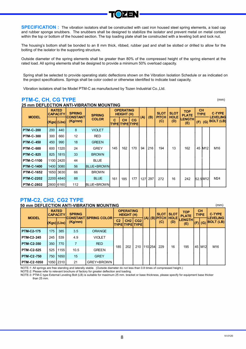
PTM-C- 200 200 440 8 VIOLET
145 162 170 94 216 194 13 162 45 M12
PTM- C- 300 300 660 12 RED
PTM-C- 450 450 990 18 GREEN
PTM-C- 600 600 1320 24 GREY
PTM-C- 825 825 1815 33 BROWN
PTM- C-1100 1100 2420 44 BLUE
PTM- C-1400 1400 3080 56 BLUE+BROWN
M16
1650 3630 66 BROWN
BLUE+BROWN
MODEL
RATED CAPACITY SPRING
CONSTANT (Kg/mm)
SPRING COLOR
OPERATING HEIGHT (H)
(A) (B) SLOT PITCH
(C)
SLOT HOLE
(D)
TOP PLATE
LENGTH (E)
CH TYPE C-TYPE
LEVELING BOLT (LB) (Kgs) (Lbs)
C2 TYPE
CH2 TYPE
CG2 TYPE
(F) (G)
PTM-C2-175 175 385 3.5 ORANGE
185 202 210 110 254 229 16 195
PTM-C2- 245 245 539 4.9 VIOLET
PTM- C2-350 350 770 7 RED
PTM-C2-525 525 1155 10.5 GREEN
PTM-C2-750 750 1650 15 GREY
PTM-C2-1050 1050 2310 21 GREY+BROWN
M16
Spring shall be selected to provide operating static deflections shown on the Vibration Isolation Schedule or as indicated on
the project specifications. Springs shall be color coded or otherwise identified to indicate load capacity.
Vibration isolators shall be Model PTM-C as manufactured by Tozen Industrial Co.,Ltd.
PTM-C, CH, CG TYPE 25 mm DEFLECTION ANTI-VIBRATION MOUNTING
PTM-C2, CH2, CG2 TYPE 50 mm DEFLECTION ANTI-VIBRATION MOUNTING
NOTE-1: All springs are free standing and laterally stable. (Outside diameter do not less than 0.8 times of compressed height.)
NOTE-2: Please refer to relevant brochure of factory for greater deflection and loading.
NOTE-3: PTM-C type External Leveling Bolt (LB) is suitable for maximum 25 mm. bracket or base thickness, please specify for equipment base thicker
than 25 mm.
(mm)
(mm)
PTM-C-1652
2200 4840 88
PTM-C-2202 BLUE
PTM-C-2802 2800 6160 112
8
161 185 177 127 297 272 16 242 52.5 M12 M24
SPECIFICATION : The vibration isolators shall be constructed with cast iron housed steel spring elements, a load cap
and rubber sponge snubbers. The snubbers shall be designed to stabilize the isolator and prevent metal on metal contact
within the top or bottom of the housed section. The top loading plate shall be constructed with a leveling bolt and lock nut.
The housing’s bottom shall be bonded to an 8 mm thick, ribbed, rubber pad and shall be slotted or drilled to allow for the
bolting of the isolator to the supporting structure.
Outside diameter of the spring elements shall be greater than 80% of the compressed height of the spring element at the
rated load. All spring elements shall be designed to provide a minimum 50% overload capacity.
45 M12

VI-01209
8
Take out the leveling bolt and lock nut from the top of the isolator.
Lift or block up the equipment’s leg or isolator bracket to 5mm higher isolator’s operating height (see catalogue) and slide the
isolators into position. Put the leveling bolt & lock nut back into position.
Transfer the equipment weight to the spring by taking two clockwise turns on each leveling bolt around the unit until the springs are
compressed just enough to remove blocks.
Tighten the lock nut to lock the assembly.
REMARKS :
INSTALLATION INSTRUCTION :
A) For PTM-C (External level adjusted) spring isolators
B) For PTM-CH & PTM-CG (Internal level adjusted) spring isolators
Check that the internal leveling nut is adjusted up to underside of the top plate.
Lift or block up the equipment to 5mm higher than isolator’s operating height (sees catalogue) and slide the isolators into position
and adjust the leveling nut until the top plate is in contact with equipment base. Insert fastening screws (if used) through the
equipment base into top of the mounting and tighten.
Transfer the equipment weight to the spring by taking two anti-clockwise turns on each leveling bolt around the unit until springs
are compressed just enough to remove blocks.
When the equipment is not subject to rise to the required height, height saving bracket may be attached to the equipment. The height of
bracket connection from the bottom of the base shall be 50mm less than the isolator’s operating height or to keep a 50mm clearance
between the ground and equipment.
DO NOT install the equipment on the support of free spring; it would cause an insufficient operating height for the spring isolator when
the installation is completed.
Weight of vertical piping and valves shall be supported by the suspension hangers or other supports.
Install the flexible joint at the completion of the installation, following the pre-extension instructions which may be specified or suggested
by the flexible joint manufacturer.
Where bolting is required, avoid a direct metal contact between bolt and mounting, to prevent transmission of acoustical frequencies;
the bolt shank shall be clear in the hole and a rubber washer used under the bolt head. Bolts shall only be tightened a half turn more
than hand tight.
1.
2.
3.
4.
1.
2.
3.
a)
b)
c)
d)
e)

VI-012010
DESCRIPTION : TOZEN PTM-D series vibration
isolators consist of free standing laterally stable steel
springs assembled into ductile iron housing assemblies
fabricated to limit vertical movement of the isolated
equipments when if equipment loads are reduced or if the
equipments are subjected to large external forces. Spring
elements are complete with an internal adjusting and
leveling bolt. Holes are provided at the upper plate for
bolting to supported equipment. A 10mm thick non-skid
noise absorbing rubber pad is bonded at the bottom plate
with holes for bolting to the structure. All the spring
elements are comply to JIS 2704 for semi-permanent use.
To assure lateral stability, outside diameter of the spring
elements do not less than 0.8 times of the compressed
height of the spring at rated load. All the spring are
designed to provide a minimum of 50% overload capacity.
PTM-D series vibration isolator are shipped with standard
deflections of 25 and 50 mm, and available up to 50mm,
with load capacities from 450 Kgs to 5,600 Kgs. Model
PTM-D spring isolators are recommended for the isolation
of vibration produced by equipment carrying a large fluid
load which may be drained, such as boilers and chillers,
and for the isolation of cooling towers, air cooled
condensers, etc, where motion due to wind loads must be
minimized.
APPLICATION :Type PTM-D mounts are typically
used to reduce the transmission of noise and vibration into
supporting structures from equipments carrying a large
fluid load that may be drained, such as boilers and for
cooling towers, which also require hold down for wind
loads.
SPECIFICATION : Vibration isolators for equipment
which is subject to load vibrations and large external or
torquing forces shall consist of laterally stable steel springs
assembled into a ductile iron housing assembly designed to
limit vertical movement of the supported equipment.
Housing assembly shall be of ductile iron members and
consist of a load transfer plate at the top complete with holes,
adjusting and leveling bolts, vertical restraints, isolation
washers and a bottom plate with non-skid noise isolation pad
and holes provided for anchoring to supporting structure.
Spring elements shall have a outside diameter not less than
0.8 times to the compressed height of the spring rated load. All
springs shall be designed to provide a minimum of 50%
overload capacity.
PTM-D - 451M, 601M, 826M, 1101M, 1401M
PTM-D2 -176, 246, 351, 526, 751, 1051
PTM-D-1652M, 2202M, 2802M
PTM-D2 1502, 2102
PTM-D-3304M, 4404M, 5604M
PTM-D2 3004, 4204
* These images are sectioned for better appearance.
PTM-D,DS,D2,DS2,DS3
RESTRAINED SINGLE AND MULTIPLE SPRING ISOLATOR
PTM-D-6606 , PTM-D-8406
Upper Plate
Bolt & Nut
Spacer
Lower Plate
Upper Cup
Leveling Bolt
Acoustic Pad
Spring Element

VI-012011
MODEL RATED CAPACITY MOUNT
CONSTANT (Kg/mm)
SPRING COLOR
OPERATING HEIGHT
(H) (Kgs) (Lbs) A B C D E F G I
PTM-D-451 450 990 18 GREEN
170 172 121 137 86 16 30 88 14
PTM-D-601 600 1320 24 GREY
PTM-D-826 825 1815 33 BROWN
PTM-D-1101 1100 2420 44 BLUE
PTM-D-1401 1400 3080 56 BLUE+BROWN
PTM-D-1652 1650 3630 66 BROWN
170 180 200 136 156 20 40 118 18 PTM-D-2202 2200 4840 88 BLUE
PTM-D-2802 2800 6160 112 BLUE+BROWN
PTM-D-3304 3300 7260 132 BROWN
185 255 167 211 123 20 48.5 135 18 PTM-D- 4404 4400 9680 176 BLUE
PTM-D-5604 5600 12320 224 BLUE+BROWN
DIMENSION (mm)
PTM-D TYPE 25mm DEFLECTION ANTI-VIBRATION MOUNTING
PTM-D2 TYPE 50mm DEFLECTION RESTRAINED SPRING ISOLATOR
243 270 193 220 22 41 194
PTM-D-6606
6600
14520
264
BLUE
8400
18480
336
BLUE+BROWN
184
4500 9900 90 GREY 250 430 310 250 260 20 65
6300 13860 126 GREY+BROWN 200
MODEL RATED CAPACITY MOUNT
CONSTANT (Kg/mm)
SPRING COLOR
OPERATING HEIGHT
(H)
DIMENSION (mm)
(Kgs) (Lbs) A B C D E F G I
PTM-D2-176 175 385 3.5 ORANGE
210 190 130 152 95 16 38 106 16
PTM-D2-246 245 539 4.9 VIOLET
PTM-D2-351 350 770 7 RED
PTM-D2-526 525 1155 10.5 GREEN
PTM-D2-751 750 1650 15 GREY
PTM-D2-1051 1050 2310 21 GREY+BROWN
PTM-D2-1502 1500 3300 30 GREY 210 232 196 187 152 20 42 120 16
PTM-D2-2102 2100 4620 42 GREY+BROWN
PTM-D2-3004 3000 6600 60 GREY 220 300 200 260 162 20 66.5 170
PTM-D2-4204 4200 9240 84 GREY+BROWN 20
NOTE-1: All springs are free standing and laterally stable.
NOTE-2: All springs are designed to provide additional travel to solid of at least 50% rated load.
NOTE-3: Please consult the representatives for a complete vibration control design
NOTE-4: PTM-DS2 is carbon steel type.
17
-
PTM-D-8406
PTM-DS2-4506
PTM-DS2-6306
VI-012012
MODEL RATED CAPACITY MOUNT
CONSTANT (Kg/mm)
SPRING COLOR
OPERATING HEIGHT
(H)
DIMENSION (mm)
(Kgs) (Lbs) A B C D E F I
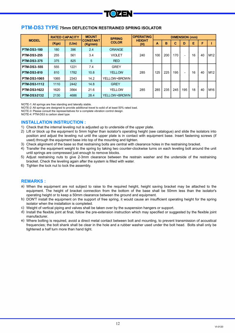
PTM-DS3-180 180 396 2.4 ORANGE
240 100 200 170 - 16 40 PTM-DS3-255 255 561 3.4 VIOLET
PTM-DS3-375 375 825 5 RED
PTM-DS3- 555 555 1221 7.4 GREY
285 125 225 195 - 16 40 M12 PTM-DS3-810 810 1782 10.8 YELLOW
PTM-DS3-1065 1065 2343 14.2 YELLOW+BROWN
PTM-DS3-1112 1110 2442 14.8 GREY
285 285 235 245 195 18 40 M16 PTM-DS3-1622 1620 3564 21.6 YELLOW
PTM-DS3-2132 2130 4686 28.4 YELLOW+BROWN
M12
NOTE-1: All springs are free standing and laterally stable.
NOTE-2: All springs are designed to provide additional travel to solid of at least 50% rated load.
NOTE-3: Please consult the representatives for a complete vibration control design.
NOTE-4: PTM-DS3 is carbon steel type
PTM-DS3 TYPE 75mm DEFLECTION RESTRAINED SPRING ISOLATOR
Check that the internal leveling nut is adjusted up to underside of the upper plate.
Lift or block up the equipment to 5mm higher than isolator's operating height (see catalogue) and slide the isolators into
position and adjust the leveling nut until the upper plate is in contact with equipment base. Insert fastening screws (if
used) through the equipment base into top of the mounting and tighten.
Check alignment of the base so that restraining bolts are central with clearance holes in the restraining bracket.
Transfer the equipment weight to the spring by taking two counter-clockwise turns on each leveling bolt around the unit
until springs are compressed just enough to remove blocks.
Adjust restraining nuts to give 2-3mm clearance between the restrain washer and the underside of the restraining
bracket. Check the leveling again after the system is filled with water.
Tighten the lock nut to lock the assembly.
When the equipment are not subject to raise to the required height, height saving bracket may be attached to the
equipment. The height of bracket connection from the bottom of the base shall be 50mm less than the isolator's
operating height or to keep a 50mm clearance between the ground and equipment.
DON'T install the equipment on the support of free spring, it would cause an insufficient operating height for the spring
isolator when the installation is completed.
Weight of vertical piping and valves shall be taken over by the suspension hangers or support.
Install the flexible joint at final, follow the pre-extension instruction which may specified or suggested by the flexible joint
manufacturer.
Where bolting is required, avoid a direct metal contact between bolt and mounting, to prevent transmission of acoustical
frequencies; the bolt shank shall be clear in the hole and a rubber washer used under the bolt head. Bolts shall only be
tightened a half turn more than hand tight.
INSTALLATION INSTRUCTION :
REMARKS :
1)
2)
3)
4)
5)
6)
a)
b)
c)
d)
e)
VI-012013
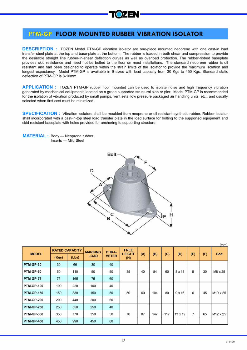
DESCRIPTION : TOZEN Model PTM-GP vibration isolator are one-piece mounted neoprene with one cast-in load
transfer steel plate at the top and base-plate at the bottom. The rubber is loaded in both shear and compression to provide
the desirable straight line rubber-in-shear deflection curves as well as overload protection. The rubber-ribbed baseplate
provides skid resistance and need not be bolted to the floor on most installations. The standard neoprene rubber is oil
resistant and had been designed to operate within the strain limits of the isolator to provide the maximum isolation and
longest expectancy. Model PTM-GP is available in 9 sizes with load capacity from 30 Kgs to 450 Kgs. Standard static
deflection of PTM-GP is 8-10mm.
APPLICATION : TOZEN PTM-GP rubber floor mounted can be used to isolate noise and high frequency vibration
generated by mechanical equipments located on a grade supported structural slab or pier. Model PTM-GP is recommended
for the isolation of vibration produced by small pumps, vent sets, low pressure packaged air handling units, etc., and usually
selected when first cost must be minimized.
SPECIFICATION : Vibration isolators shall be moulded from neoprene or oil resistant synthetic rubber. Rubber isolator
shall incorporated with a cast-in-top steel load transfer plate in the load surface for bolting to the supported equipment and
skid resistant baseplate with holes provided for anchoring to supporting structure.
MATERIAL : Body — Neoprene rubber
Inserts — Mild Steel
(mm)
RATED CAPACITY MARKING
LOAD DURA- METER
FREE HEIGHT
(H) (A) (B) (C) (D) (E) (F) Bolt
(Kgs) (Lbs)
PTM-GP-30 30 66 30 40
35 40 84 60 8 x 13 5 30 M8 x 25 PTM-GP-50 50 110 50 50
PTM-GP-75 75 165 75 60
PTM-GP-100 100 220 100 40
50 60 104 80 9 x 16 6 45 M10 x 25 PTM-GP-150 150 330 150 50
PTM-GP-200 200 440 200 60
PTM-GP-250 250 550 250 40
70 87 147 117 13 x 19 7 65 M12 x 25 PTM-GP-350 350 770 350 50
PTM-GP-450 450 990 450 60
MODEL
PTM-GP FLOOR MOUNTED RUBBER VIBRATION ISOLATOR

VI-012014
TYPE ITEM NO.
DIMENSION (mm) ALLOWABLE LOADING (kg/cm2) t W L
Square PT-1030 10 300 300 4
PT-1100 10 100 1000 4
PT-1150 10 150 1000 4
PT-1300 10 300 1000 4
PT-1510 15 100 1000 4
PT-1515 15 150 1000 4
PT-1530 15 300 1000 4
PT-2010 20 100 1000 4
PT-2015 20 150 1000 4
PT-2030 20 300 1000 4
Rectangular
MASS (kgs)
0.9
1.0
1.5
3.0
1.6
2.4
4.8
2.2
3.3
6.5
Square Type (PT-1030) Rectangular Type
DESCRIPTION : TOZEN PT-MAT can be cut out to any suitable square or rectangular sizes easily to suit various
mounting footings of machines or equipment for effective isolation of shock and vibration. In most cases no anchor bolting
is required. Ingeniously designed having ribs of upper and lower surface arranged at right angles and optimum rubber
hardness (55-60 durameter) PT-MAT performs effectively against shock and vibration both laterally and vertically. At the
same time noise caused by vibration is thus also reduced. In view of design and material aspects PT-MAT can withstand
and absorb greater impact from various machines and equipment. It provides larger buffer capacity per unit area.
Compared with other vibration isolation devices PT-MAT is the most economical type available due to mass production.
Each sheet can be fully utilized without waste. The 3 different thickness(t) of PT-MAT are recommended for 2-4 kgf/cm2.
APPLICATION : Vibration isolation for equipment like packaged air handling units, pumps, etc.
Isolation between the pipe and pipe support, etc.
Load Stress-Deflection and Natural Frequency-Load Stress Relationship
Fig.1 Characteristic of Load Stress~Deflection Fig.2 Characteristic of Natural Frequency~Load Stress
PT-MAT VIBRATION ISOLATING RUBBER PAD

VI-012015
DESCRIPTION : TOZEN Model PT-MOUNT vibration isolators are one piece moulded neoprene with two
cast-in load transfer steel plates incorporate with bolt, spring washer and lock nut at the top and the bottom load
surface for attachment to supported equipment. The synthetic rubber compound is oil resistant and has been
designed to operate within the strain limits of the isolator to provide the maximum isolation and longest
expectancy.
(mm)
MODEL RATED
CAPACITY
MAXIMUM
STATIC
DEFL. A
(Kgs)
10~25 17 2 20
20~40 17 2 25
30~75 18 4 35
60~110 21 5 45
80~175 30 6 55
140~320 66 5 65
260~400 62 6 75
320~550 70 8 90
B
15
18
26
34
40
34
42
50
H
51
54
70
80
104
108
116
124
D
M6
M6
M8
M8
M10
M12
M12
M12
450~950 86 8 110 66 158 M16
800~2000 186 8 150 70 172 M20
STATIC
SPRING
RATE (Kgf/mm)
NATURAL
PT-MOUNT VIBRATION ISOLATING RUBBER
PTM-01
PTM-02
PTM-04
PTM-06
PTM-08
PTM-09
PTM-10
PTM-11
PTM-12
PTM-13
-G-20
PTM-G-35
PTM-G-70
PTM-G-120
PTM-G-175
PTM-G-335
PTM-G-435
PTM-G-600
PTM-G-700
PTM-G-1500
OLD MODEL
PTM
Model: PT-MOUNT is recommended for the isolation
of vibration produced by small pumps, vent sets, low
pressure packaged air handling units, etc., and usually
selected when first cost must be minimized.
FREQUENCY
Hz
23~15
17~12
14~8.9
11~7.8
11~7.4
12~8.2
8.8~7.1
8.4~6.4
7.8~5.4
8.7~5.5
Standard Defection: 2~11 mm
VI-012016
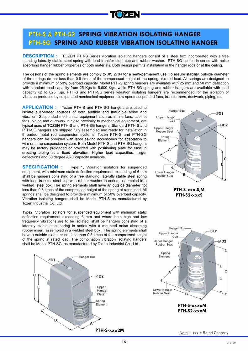
DESCRIPTION : TOZEN PTH-S Series vibration isolating hangers consist of a steel box incorporated with a free
standing-laterally stable steel spring with load transfer steel cup and rubber washer. PTH-SG comes in series with noise
absorbing hanger rubber properties of both materials. Both design permits installation in the hanger rods or at the ceiling.
The designs of the spring elements are comply to JIS 2704 for a semi-permanent use. To assure stability, outside diameter
of the springs do not less than 0.8 times of the compressed height of the spring at rated load. All springs are designed to
provide a minimum of 50% overload capacity. Model PTH-S spring hangers are available with 25 mm and 50 mm deflection
with standard load capacity from 25 Kgs to 5,600 Kgs, while PTH-SG spring and rubber hangers are available with load
capacity up to 825 Kgs. PTH-S and PTH-SG series vibration isolating hangers are recommended for the isolation of
vibration produced by suspended mechanical equipment, low speed suspended fans, transformers, ductwork, piping, etc.
APPLICATION : Tozen PTH-S and PTH-SG hangers are used to
isolate suspended sources of both audible and inaudible noise and
vibration. Suspended mechanical equipment such as in-line fans, cabinet
fans, piping and ductwork in close proximity to mechanical equipment, are
typical uses of TOZEN PTH-S and PTH-SG hangers. Standard PTH-S and
PTH-SG hangers are shipped fully assembled and ready for installation in
threaded metal rod suspension systems. Tozen PTH-S and PTH-SG
hangers can be provided with labor saving accessories for adaptation to
wire or strap suspension system. Both Model PTH-S and PTH-SG hangers
may be factory preloaded or provided with positioning plate for ease in
erecting piping at a fixed elevation. Higher load capacities, larger
deflections and 30 degree ARC capacity available.
SPECIFICATION : Type 1, Vibration isolators for suspended
equipment, with minimum static deflection requirement exceeding of 6 mm
shall be hangers consisting of a free standing, laterally stable steel spring
with load transfer steel cup with rubber washer in series, assembled in a
welded steel box. The spring elements shall have an outside diameter not
less than 0.8 times of the compressed height of the spring at rated load. All
springs shall be designed to provide a minimum of 50% overload capacity.
Vibration isolating hangers shall be Model PTH-S as manufactured by
Tozen Industrial Co.,Ltd.
Type2, Vibration isolators for suspended equipment with minimum static
deflection requirement exceeding 6 mm and where both high and low
frequency vibrations are to be isolated, shall be hangers consisting of a
laterally stable steel spring in series with a mounted noise absorbing
rubber insert, assembled in a welded steel box . The spring elements shall
have a outside diameter not less than 0.8 times of the compressed height
of the spring at rated load. The combination vibration isolating hangers
shall be Model PTH-SG, as manufactured by Tozen Industrial Co., Ltd.
Note : xxx = Rated CapacityPTH-S-xxx2M
PTH-S-xxxxM PTH-S2-xxxM
PTH-S-xxx,S,M PTH-S2-xxxS
PTH-S & PTH-S2 SPRING VIBRATION ISOLATING HANGER
PTH-SG SPRING AND RUBBER VIBRATION ISOLATING HANGER

VI-012017
Consider the height and location of the hanger and prepare the
upper and lower hanging rod(bolt) in same proper length.
Attach the upper hanging rod(bolt) to the ceiling.
Connect the lower hanging rod (bolt) to the hanger. Pre-compress
the hanger spring element (Approx. 10 mm) by tighten a restrain
nut and washer at the bottom of the hanger.
Attach the hanger to the upper hanging rod(bolt).
Attach the hanging rod(bolt) to the pipe, duct or equipment
bracket.
Install all other hangers by repeating instruction 1-5.
After the pipe or equipment is filled with water, release the
restraint nut. Leveling adjust the hanger by the nut at the top of
the element to obtain even level installation.
Final check the spring hanger in a proper deflection and don’t
install the hanging rod(bolt) in a inclined position.
MODEL RATED CAPACITY SPRING CONSTANT
(Kg/mm) SPRING COLOR
DIMENSION (mm)
(Kgs) (Lbs) A B C D1 D2 E F
PTH-S TYPE 25 MM DEFLECTION
PTH-S-25 25 55 1 WHITE
58
85
145
13
15
92
-
PTH-S-35 35 77 1.4 YELLOW
PTH-S-50 50 110 2 ORANGE
PTH-S-80 80 176 3.2 VIOLET
PTH-S-120 120 264 4.8 RED
PTH-S-175 175 385 7 GREY 58 85 145 15 15 92 -
PTH-S-225 225 495 9 BROWN
84 120 180 17 18 115 - PTH-S-300 300 660 12 RED
PTH-S-450 450 990 18 GREEN
PTH-S-600 600 1320 24 GREY
105 125 200 25 18 123 - PTH-S-825 825 1815 33 BROWN
PTH-S-1100 1100 2420 44 BLUE
PTH-S-1202 1200 2640 48 GREY
124 225 278 30 30 146 - PTH-S-1652 1650 3630 66 BROWN
PTH-S-2202 2200 4840 88 BLUE
PTH-S-2802 2800 6160 112 BLUE+BROWN
PTH-S-3304 3300 7260 132 BROWN
195 235 300 36 36 148 - PTH-S-3604 3600 7920 144 BROWN+GREY
PTH-S-4404 4400 9680 176 BLUE
PTH-S-5604 5600 12320 224 BLUE+BROWN
PTH-S, PTH-S2, PTH-SG
PTH-SG-xxxM, PTH- SG2 - xxxM
PTH-S-xxx4M, PTH -S2-xxx4M PTH-SG-xxxS, PTH-SG-xxxM, PTH-SG2-xxxS, S
INSTALLATION INSTRUCTION :
1)
2)
3)
4)
5)
6)
7)
8)
PTH-S-10
PTH-S-15
10
15 33
22 0.4
0.6
GREEN
BLUE

VI-012018
NOTE-1: All springs have an minimum additional travel to solid equal to 50% of rated load.
NOTE-2: Please refer to relevant brochure or consult factory for greater deflection and loading.
NOTE-3: Spring constant applies to spring only.
NOTE-4: Please consult factory for pre-compressed model and 30 degree arc capacity.
MODEL RATED CAPACITY SPRING CONSTANT
(Kg/mm) SPRING COLOR
DIMENSION (mm)
(Kgs) (Lbs) A B C D1 D2 E F
PTH-S2-25 25 55 0.5 WHITE
84 120 210 15 18 135 -
PTH-S2-35 35 77 0.7 YELLOW
PTH-S2-50 50 110 1 ORANGE
PTH-S2-80 80 176 1.6 VIOLET
PTH-S2-125 125 275 2.5 RED
PTH-S2-175 175 385 3.5 GREY
PTH-S2-250 250 550 5 BROWN
105 140 255 21 24 168 -
PTH-S2-350 350 770 7 RED
PTH-S2-525
525 1155 10.5 GREEN
PTH-S2-750 750 1650 15 GREY
PTH-S2-1052 1050 2310 21 GREEN
PTH-S2-1502 1500 3300 30 GREY
PTH-S2-2102 2100 4620 42 GREY+BROWN
PTH-S2-3004 3000 6600 60 GREY
PTH-SG TYPE 25 MM DEFLECTION
PTH-SG-25 25 55 1.0 WHITE
58
85
180
15
92
PTH-SG-35 35 77 1.4 YELLOW
PTH-SG-50 50 110 2.0 ORANGE
PTH-SG-80 80 176 3.2 VIOLET
PTH-SG-120 120 264 4.8 RED
84
130
220
18
18
115
44
PTH-SG- 300 660 12 RED
PTH-SG-450 450 990 18 GREEN
PTH-SG-600 600 1320 24 GREY
PTH-SG-825 825 1815 33 BROWN
PTH-SG2 TYPE 50 MM DEFLECTION
PTH-SG2-25 25 55 0.5 WHITE
84 140 235 18 135 32.5
PTH-SG2-35 35 77 0.7 YELLOW
PTH-SG2-50 50 110 1 ORANGE
PTH-SG2-80 80 176 1.6 VIOLET
PTH-SG2-125 125 275 2.5 RED
PTH-SG2-175 175 385 3.5 ORANGE
120 160 290 18 24 168 44 PTH-SG2-245 245 539 4.9 VIOLET
PTH-SG2-350 350 770 7 RED
PTH-SG2-525 525 1155 10.5 GREEN 120 180 310 20 24 168 50
PTH-SG2-750 750 1650 15 GREY
PTH-SG-175 175 385 7.0 GREY
PTH-S, PTH-S2, PTH-SG (continued)
4204PTH S2- - 4200 9240 84 GREY+BROWN
222 260 325 52 38 194 -
16 31
120 170 270 20 18 124 50
16
146 260 325 30 30 190 -
PTH-S2 TYPE 50 MM DEFLECTION
300
PTH-SG-
440
200 200 8.0 VIOLET
VI-012019
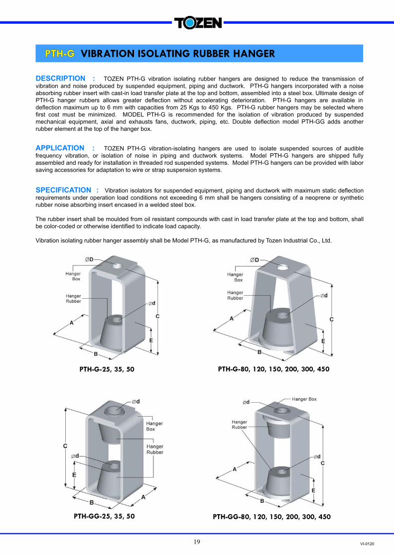
PTH-G-25, 35, 50 PTH-G-80, 120, 150, 200, 300, 450
PTH-GG-25, 35, 50 PTH-GG-80, 120, 150, 200, 300, 450
DESCRIPTION : TOZEN PTH-G vibration isolating rubber hangers are designed to reduce the transmission of
vibration and noise produced by suspended equipment, piping and ductwork. PTH-G hangers incorporated with a noise
absorbing rubber insert with cast-in load transfer plate at the top and bottom, assembled into a steel box. Ultimate design of
PTH-G hanger rubbers allows greater deflection without accelerating deterioration. PTH-G hangers are available in
deflection maximum up to 6 mm with capacities from 25 Kgs to 450 Kgs. PTH-G rubber hangers may be selected where
first cost must be minimized. MODEL PTH-G is recommended for the isolation of vibration produced by suspended
mechanical equipment, axial and exhausts fans, ductwork, piping, etc. Double deflection model PTH-GG adds another
rubber element at the top of the hanger box.
APPLICATION : TOZEN PTH-G vibration-isolating hangers are used to isolate suspended sources of audible
frequency vibration, or isolation of noise in piping and ductwork systems. Model PTH-G hangers are shipped fully
assembled and ready for installation in threaded rod suspended systems. Model PTH-G hangers can be provided with labor
saving accessories for adaptation to wire or strap suspension systems.
SPECIFICATION : Vibration isolators for suspended equipment, piping and ductwork with maximum static deflection
requirements under operation load conditions not exceeding 6 mm shall be hangers consisting of a neoprene or synthetic
rubber noise absorbing insert encased in a welded steel box.
The rubber insert shall be moulded from oil resistant compounds with cast in load transfer plate at the top and bottom, shall
be color-coded or otherwise identified to indicate load capacity.
Vibration isolating rubber hanger assembly shall be Model PTH-G, as manufactured by Tozen Industrial Co., Ltd.
PTH-G VIBRATION ISOLATING RUBBER HANGER

VI-012020
NOTE-1: Hanger elements have similar straight line deflection curve.
NOTE-2: Please refer to relevant brochure or consult factory for wire or strap suspension systems.
PTH-G, PTH-GG
RUBBER HANGER
MODEL DESIGN LOADING RUBBER
COLOR CODE
MAXIMUM STATIC DEFL.
DURA- METER
A B C d D
(Kgs) (Lbs) PTH-G PTH-GG PTH-G PTH-GG
PTH-G-25 25 55 WHITE
4
40
37 45 90 115 11 11 11 PTH-G-35 35 77 YELLOW 50
PTH-G-50 50 110 ORANGE 55
PTH-G-80 80 176 PINK
5
40
60 75 105 140 16 16 15 PTH-G-120 120 264 RED 50
PTH-G-150 150 330 ORANGE 55
PTH-G-200 200 440 PINK
6
40
85 103 132 195 18 18 18 PTH-G-300 300 660 RED 50
PTH-G-450 450 990 GREEN 55
E
28
37
50
PTH-G
(mm)

VI-0120
TOZEN INDUSTRIAL CO., LTD.
3388/62 18TH FLOOR, SIRINRAT BLDG.,
RAMA IV RD., BANGKOK 10110 THAILAND
TEL : (66) 0-2029-0100
FAX : (66) 0-2029-0111
URL : www.tozen.co.th
TOZEN CORPORATION
8-4, ASAHI YOSHIKAWA
SAITAMA 342-008 JAPAN
TEL : 048-993-1030
FAX : 048-993-1038
A j o i n t r e l i a n c e