Version 03 Risk Control - cowensrs.co.uk · Risk Control Protection of buildings against lightning...
16
administered by Risk Control Protection of buildings against lightning strike RC35 First published 2004 Version 03
Transcript of Version 03 Risk Control - cowensrs.co.uk · Risk Control Protection of buildings against lightning...

administered by
Risk ControlProtection of buildings against lightning strike
RC35First published 2004 Version 03

IMPORTANT NOTICE
This document has been developed through the RISCAuthority and published by the Fire Protection Association (FPA). RISCAuthority membership comprises a group of UK insurers that actively support a number of expert working groups developing and promulgating best practice for the protection of people, property, business and the environment from loss due to fire and other risks. The technical expertise for this document has been provided by the Technical Directorate of the FPA, external consultants, and experts from the insurance industry who together form the various RISCAuthority Working Groups. Although produced with insurer input it does not (and is not intended to) represent a pan-insurer perspective. Individual insurance companies will have their own requirements which may be different from or not reflected in the content of this document.
The FPA has made extensive efforts to check the accuracy of the information and advice contained in this document and it is believed to be accurate at the time of printing. However, the FPA makes no guarantee, representation or warranty (express or implied) as to the accuracy or completeness of any information or advice contained in this document. All advice and recommendations are presented in good faith on the basis of information, knowledge and technology as at the date of publication of this document.
Without prejudice to the generality of the foregoing, the FPA makes no guarantee, representation or warranty (express or implied) that this document considers all systems, equipment and procedures or state-of-the-art technologies current at the date of this document.
Use of, or reliance upon, this document, or any part of its content, is voluntary and is at the user’s own risk. Anyone considering using or implementing any recommendation or advice within this document should rely on his or her own personal judgement or, as appropriate, seek the advice of a competent professional and rely on that professional’s advice. Nothing in this document replaces or excludes (nor is intended to replace or exclude), entirely or in part, mandatory and/or legal requirements howsoever arising (including without prejudice to the generality of the foregoing any such requirements for maintaining health and safety in the workplace).
Except to the extent that it is unlawful to exclude any liability, the FPA accepts no liability whatsoever for any direct, indirect or consequential loss or damage arising in any way from the publication of this document or any part of it, or any use of, or reliance placed on, the content of this document or any part of it.
CONTENTS
Scope 3
Synopsis 3
Definitions 3
Introduction 3
Recommendations
1. Understanding lightning 4
2. Principles of lightning protection 4
3. Determining the need for lightning protection 4
4. System design guidelines 5
5. System components and installation 6
6. Inspection and maintenance 7
7. Developments in lightning protection 7
8. Checklist 9
References 8
Further reading 8
SCOPE
This document aims to provide an understanding of the
phenomenon of lightning and the general requirements for the
design, installation, inspection and testing of lightning protection
systems for buildings and structures. It does not provide details
on the protection of high-risk buildings, such as those used
for the manufacture and storage of flammable liquids/gases
and explosives, nor protection of electronic equipment against
electrical disturbances arising from lightning. Also, special risks
such as complex buildings, air-supported structures, tents/
marquees and metal scaffold structures are not covered in detail
in this document.
SYNOPSIS
This document explains the changes from BS 6651: 1999 to
BS EN 62305: Parts 1 to 4: 2006 and outlines the new risk
assessment process.
Although the principle threat from a lightning strike is to life
safety, there is also a direct threat to property and a potential
to paralyse a business, causing considerable disruption and
financial loss.
Despite the modification of the method of probability calculation,
the same risk point (10-5) as in the old standard triggers the
need for building protection.
DEFINITIONS
Air termination device
System component designed to intercept a lightning discharge.
Bonding
Means by which components of lightning system and building
metalwork are connected together to minimise dangerous
potential differences and side flashing.
Collection area
Total plan area associated with a structure (m2 × 10-6) which
gives an indication of the number of strikes to a structure when
multiplied by the local flash density value in flashes/km2/year.
Down conductor
Conductor connecting air terminations and earth terminations.
Earth termination
System component that discharges lightning current to ground.
Surge
Short duration increase in voltage or current.
Surge protector
Protective device to limit surge voltages and currents.
Zone of protection
Volume within which a lightning conductor or lightning conductor
system gives protection against a direct lightning strike by
capturing the strike to itself.
Note: The style of writing decimals in BS EN 62305 adopts the
European notation throughout the four parts of BS EN 62305.
Thus, a comma is used instead of a full stop to indicate a decimal
point. For example, 21.6 is written as 21,6.
INTRODUCTION
Even though the frequency of lightning activity in the UK is
relatively low when compared globally, it remains a risk to life and
property and needs to be assessed adequately.
A direct lightning strike may cause damage to the structure of a
building and secondary effects due to voltage surges may cause
damage to electric and electronic equipment. The damage due to
secondary (indirect) effects has increased over the years in line with
the increased use of high value electronic equipment in buildings
and the increased potential susceptibility of computer systems.
The key function of a lightning protection system is to intercept a
lightning strike and provide a path of low resistance to earth along
which the discharge can travel and dissipate safely. Without this,
the lightning would follow paths of high resistance through the
building’s structure of wood, brick, concrete or similar materials
resulting in the generation of heat and mechanical forces
which can cause extensive damage, including fire. Lightning
damage to electric and electronic equipment is managed by
way of strategically placed surge arrestors, suitable location of
equipment and appropriate bonding and cable protection.
The need for protection against the effects of lightning should
be determined by carrying out a risk assessment. Separate
assessments for direct and secondary effects were detailed in
BS 6651: 1999: Code of practice for protection of structures
against lightning (ref. 1) and other, similar, codes of practice.
However from August 2008 this Code of Practice was superseded
by BS EN 62305 (ref. 2).
The new standard consists of four parts:
• Part1:Generalprinciples;
• Part2:Riskmanagement;
• Part3:Physicaldamagetostructuresandlifehazard;and
• Part4:Electricalandelectronicsystemswithinstructures.
The new risk assessment process addresses four types of loss:
• L1:lossofhumanlife;
• L2:lossofservicetothepublic;
• L3:lossofculturalheritage;and
• L4:lossofeconomicvalue.
The need for lightning protection is evaluated according to risk
assessments of social values L1, L2 and L3. If these exceed
a tolerable level then protection against lightning is required.
(Detailed information regarding the assessment process is set
out in Part 2 of the standard.)
In addition to assessing the need for the structure to be protected,
the economic benefits of providing protection measures should
also be evaluated in order to reduce the economic loss L4. In this
case, lightning protection is effective if the loss in the presence of
protection measures plus the cost of the measures is assessed
to be lower than the total loss without the protection measures.
Although in most cases life safety criteria are likely to be the most
important aspect of the assessment process, there may be cases
where the need for protection will be necessary irrespective of the
results of the economic assessment. This could be the case, for
example, when considering the protection of heritage properties.
Although lightning protection is not a legal requirement for all
buildings and structures, the requirements of the Electricity at
Work Regulations 1989 (ref. 3) will apply to most businesses.
Regulation 6 requires electrical installations to be protected from
theharmfuleffectsofnaturalhazards,whichincludelightning.
Lightning protection systems, to be effective, should be designed,
installed, inspected and maintained in accordance with the new
standard using high quality, tested and approved components
3
and preferably by a member of the Association of Technical
Lightning and Access Specialists (ATLAS).
As is the case with all British Standards, BS EN 62305: Parts 1
to 4 are not retrospective and thus existing lightning protection
systems designed to the previous standard need not be altered
unless significant changes have been made to the structure.
RECOMMENDATIONS
1. Understanding lightning
Lightning is the result of the discharge from a region of high
electrical potential in a cloud to a point of low potential during a
thunderstorm. Although there appears to be some debate as to
exactly how the polarisation of a cloud occurs, there is general
consensus that clouds are negatively charged at the base and
positively charged at the top.
Thunderclouds, which are electrically charged bodies suspended
in air, induce a positive charge on the surface of the earth below.
As the intensity of the storm increases the build up of potential
in the cloud continues until the electrical energy is released in
the form of a flash of lightning. The initial release consists of an
invisible stepped leader which normally travels from the cloud
to the ground. The visible flash, however, is the main stroke (or
‘return stroke’) which travels back from the earth to the cloud.
The average duration of a lightning flash is 0.25 seconds. Most
lightning strikes to earth are negative and travel from the base of the
thundercloud to the ground. Positive strikes, where the discharge
is from the earth’s surface to a cloud, can occur under certain
specialised conditions, as from very tall masts and mountain
tops. Strikes to ground will normally go to elevated objects (trees,
buildings etc) but on flat ground will go straight to the ground.
Areas that have large numbers of thunderstorm days per year are
likely to experience the highest rate of lightning flashes to ground.
LightningactivityvariesacrosstheUK;BSEN62305-2,page151
indicates that there is more activity in the east than the west and
more in the south than the north, with central England being the
highest, at about 1 flash/km2/yr. It is important to understand that
the values on the map are very long term averages, so that in any
particular area a strike might occur tomorrow, or next week but
then possibly not for several years.
This may change, however, as the pattern of lightning activity
is changing from year to year in line with perturbations in the
global climate.
Thehazardsposedbylightningstrikesincludelossoflife,injury,
fire and other property damage. In particular, lightning strikes to
structures may have both direct and secondary effects. Direct
effects include physical damage to a building and the possibility
of fire, while secondary effects include damage to electrical
and electronic equipment as a result of voltage/current surges
produced in wiring and cables resulting from a strike to the
building or nearby.
2. Principles of lightning protection
The first successful attempt to prevent lightning damage to
buildings was in the middle of the eighteenth century when
Benjamin Franklin fitted, on his house, the first lightning conductor
(or Franklin Rod, as it became known, particularly in the USA).
Lightning protection systems provide a path of low resistance/
inductance by which a lightning discharge can enter or leave the
earth without causing damage. Without an adequate conducting
path, a lightning discharge would follow a path of high resistance
through the brick, concrete or wooden structure of a building
resulting in damage caused by the resulting high temperatures
and mechanical forces. All metallic parts of a building might
be able to serve as lightning protection components if they are
electrically conducting from the top of the building to earth (for
example steel stanchions and beams, the reinforcing bars of
concrete, or metallic roof skins) and if there is sufficient metal.
Lightning protection is described in BS EN 62305: Parts 1
to 4; protection is based on the ‘Faraday cage’ principle. An
understanding of the principles of the Faraday cage is central to
understanding the function of conventional lightning protection
systems. A Faraday cage, named after the famous British
scientistMichaelFaraday,isanassemblyofverticalandhorizontal
conductors forming an interconnected ‘cage’ which when used
on a building for lightning protection, considerably reduces the
currents, and magnetic and electric fields inside the building,
owing to the ‘shielding’ effect of the numerous conductors. It
does not form a complete shield to the whole spectrum of
electromagnetic interference, but is particularly useful for lightning.
In addition to the direct effects of lightning, the secondary effects
– such as surges along electrical and electronic services entering
and leaving premises – may need to be eliminated by way of
strategically placed surge arrestors, or other methods.
Generally, the parts of a structure most likely to be struck by
lightning are those that project above the surrounding structure.
These include:
• flagpoles;
• chimneys;
• towers;
• elevatedwatertanks;
• roofstructures;
• steeples;and
• radio,television,mobilephoneandmicrowavemasts.
Other structures which may require lightning protection include:
• air-supportedstructures;
• watercraft;
• tents;
• bridges;
• treesneartobuildingsorofhistoricvalue;
• fixed,above-groundtanksofflammableliquid;
• scaffolding;and
• windmills.
Modern lightning protection systems consist of:
• air termination devices on the roof and elevated parts
ofastructure;
• earthterminationdevices;
• down conductors connecting the air termination devices
totheearthterminationdevices;and
• devices to isolate or electrically bond metal building
components in close proximity to the components of the
lightning protection system to prevent side flashing.
4

3. Determining the need for lightning protection
Buildings should be subjected to a lightning risk assessment;
BS EN 62305-2: Protection against lightning: Risk
management (ref. 2) describes risk assessment methods.
In some cases, the need for protection will be obvious (for
example, in the cases of flammable liquid/explosive risks, large
public assembly occupancies and tall structures). However, for
less obvious cases, the following section describes the BS EN
62305-2 approach.
3.1 Risk analysis
Risk analysis is based on a similar method to BS 6651 and
advocates, first, determining the risk of a structure being hit by
lightning. The first most notable change is that instead of a 1:1 ratio
(that is, a slope of a 45˚ angle down from the top of the building),
a72˚angle isused (that is,aslopeof1vertical to3horizontal,
increasing the collection area by nine times for very small plan
area buildings or structures like masts, chimneys, or towers etc).
Figure 1: Church spire less than 20m high providing a zone of
protection at 45º to the vertical.
Source: Ecclesiastical Insurance Group/English Heritage
Following that calculation, a risk of strike is deduced by applying
a ‘location factor’, to account for the proximity of buildings, trees
etc. and their height, followed by several other factors as detailed
in Table 1.
The factors set out in Table 1 are multiplied together as for the
BS 6651 method to give the overall risk. Although the scoring
system in BS EN 62305 has been modified from that in BS
6651, a risk of 10-5 or above is still considered the point at which
protection would normally be needed. Thus, if the resulting
risk is 1 in 100,000 or higher (for example, 1 in 10,000), good
reasons would need to be formulated to support a decision not
to install suitable protection.
Table 1: Risk analysis factors. (All references refer to BS EN 62305-2).
Symbol Definition Reference in BS 62305-2
Ad the collection area in m2 × 10-6 see paragraph A.2.1
Ng flashes/km2/year see page 151 for UK
Cd the location factor see table A.2
PB the protection factor (=1 for no lightning protection system as is normally the case for an initial risk assessment)
see table B.2
hz a factor depending on specialhazard
see table C.5
rp a fire protection factor (normally 1) see table C.3
rf a further fire factor (=10-2 for most buildings)
see table C.2
Lf a factor concerning physical loss see table C.7
3.2 Secondary effect risk assessment
The purpose of this assessment is to determine the risk
to all electrical and electronic equipment (such as CCTV,
communications and data processing equipment) from direct
discharges and induced currents.
The probability is determined by taking into consideration the
lightning flash density and the effective collection area. The
effective collection area is dependent on:
• theplanareaofthestructure;
• thelocalisedareaoverwhichanincreaseingroundelectrical
potentialduetoastrikecouldaffectthebuilding;
• thecollectionareaofanyadjacentstructurethathaselectrical
orelectronicconnectionstothestructure;
• thecollectionareaofanyincomingmainsservices;and
• thecollectionareaofdatalinestakingintoconsiderationthe
type of cable used.
The vulnerability of the equipment to damage will depend on the
probability of a strike and the following weighting factors:
• the type of structure. Buildings with lightning protection in
accordance with BS EN 62305 will be allocated the lowest
weightingvalue;
• thetypeofshieldingarrangements;
• theriskoffire(forexamplethepotentialofanexplosionfrom
petrochemcalorsimilarhazards);and
• theriskofexplosion.
The final decision to provide secondary protection is made
after taking into consideration all the possible consequential
effects of damage to critical electrical and electronic equipment.
Depending on the severity of the risk, protection, consisting of
screening and a coordinated set of surge protection devices may
be required. The following are examples where surge protection
may be appropriate:
• electricalpanelsandswitchgear thatbringsupplies into the
buildingfromthemainssupply;
• electricalpanelsandswitchgearthattakethesupplytoother
buildingsandfacilities;
• power distribution systems within buildings between the
incoming mains distribution panel and the supply side of
asocketoutletorfusedconnection;
• inside thecabinetsofequipmentnotservedbyasocketor
fusedoutlet;
• theloadsideofsocketsorfusedconnections;
• telecommunicationlinesentering(orleaving)abuilding.
It is particularly important that special attention is given to
parts of the building where a number of services are in the
same ‘service tunnel’ (for example, electricity cables, plumbing,
telecommunications and computer network cabling). A lightning
strike in this area of a building can paralyse a business, causing
considerable disruption and financial loss.
5

4. System design guidelines
4.1 Zone of protection
The zone of protection represents the volume that a lightning
conductor, or assembly of conductors protects against a direct
strike. There are several significant differences between BS
6651andBSEN62305inhowthezoneofprotectionisdefined.
Principally, BS EN 62305 specifies four different protection levels,
I to IV, of which for general purpose buildings (that is, not having
fire or explosion risk etc), level III is the most similar to BS 6651,
and would be appropriate for most structures. (See pages 15-16
of BS EN 62305-3.)
High buildings are at risk from a strike to the side. For level III
protection for buildings over 45m high and complex structures
ofanyheight,thezoneofprotectionisdeterminedusingarolling
sphere method, for which the rolling sphere radius is 45m. This
method of assessing the protected volume takes into account the
risk of strikes to the side of a building.
The rolling sphere method is based on the likely behaviour of
lightning flashes. Flashes are preceded by a downward leader
that deposits charge along its route. As this leader progresses,
a charge of opposite sign is induced on the surface of the earth
and on trees, buildings and other structures, until the electric field
is sufficiently high for an upward leader to be launched to meet
6
the downward leader. Because the upward leader is launched from
the point of greatest electric field intensity, and is not constrained to
go vertically upwards, it can travel in any direction before making the
final jump to meet the downward leader.
The points equidistant from the ends of the leaders before the final
jump are assumed to be equally likely to receive a lightning strike
and therefore the surface of a sphere centred on the position of the
leader before the last step defines the positions to which the leader
could jump.
The possible positions for the leader to approach may be simulated
by rolling an imaginary sphere, of radius equal to the last step length
(45m), over the building down to ground level.
High risk structures such as buildings housing flammable liquids
or explosives may need a higher level of protection involving a
smaller zone of protection. In these instances, specialist advice
should always be sought, and BS EN 62305 gives higher classes of
protection labelled I and II with smaller rolling sphere radii and smaller
cone angles.
4.2 Design process
Lightning protection, in common with other forms of fire protection,
should be considered at the building design stage. This will help to
ensure cost-effective installation (for example by utilising structural
steel) and an aesthetically acceptable design. It is also important that
there is effective protection in place from the earliest opportunity
as new building works are as vulnerable to structural damage as
completed ones.
The design of lightning protection systems should only be undertaken
by a suitably experienced engineer. Consultation with and approval
of the system should also be sought from the insurers of the premises.
Structures requiring protection should be provided with a fully
interconnected Faraday cage system in accordance with BS EN
62305 with no part of the structure protected in isolation.
5. System components and installation
5.1 Air termination devices
Airterminationdevicesconsistofaseriesofverticaland/orhorizontal
conductors to intercept the lightning discharge immediately above
the vulnerable part of the building. When installing air termination
devices, measures should include (level III protection):
5.1.1 Ensuring that no part of the roof is more than 7.5m from the
nearesthorizontalconductor.
5.1.2 Usingagridnetworkofmeshsizenogreaterthan15mby15m
on large, flat roofs.
5.1.3 Providing additional conductors on multiple ridge roofs where the
distance between the ridges renders them necessary.
5.1.4 Using aluminium, copper or galvanised steel strips or
rods (20mm x 2.5mm strips or 8mm diameter rods
are acceptable, or stranded conductors as specified in
BS EN 62305.)
5.1.5 Fixing centres: the BS EN 62305-3 specifies on page 96 Table
E 1 that for solid round conductors as air terminations, both
horizontalandvertical,fixingcentresof1mareused.Fortape
andstrandedconductors0.5m isspecified forallhorizontal
and vertical conductors, except vertical ones up to 20m above
ground, but 0.5m thereafter.
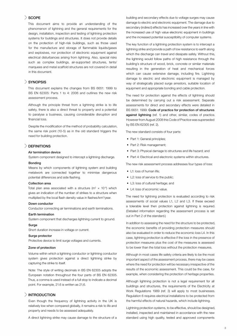
Table 2: Maximum values of rolling sphere radius, mesh size and protection angle corresponding to the class of lightning protection system. (From BS EN 62305-3: 2006).
Protection Method
Class of lightning protection system
Rolling sphere radius r(m)
Mesh size w(m) Protection angle
I 20 5 x 5
See Figure below
II 30 10 x 10
III 45 15 x 15
IV 60 20 x 20
80
70
60
50
40
30
20
10
0
0 2 10 20 30 40 50 60
H mIEC 2095/05
Class ofLPS
I II IIIIV
Imaginary ball,radius 60m
Figure 2: Factory building over 20m high, the areas touched by the rolling sphere need protection

5.2 Down conductors
The down conductors provide paths of low resistance/inductance
from the air termination devices to the earth terminations. When
installing down conductors, measures should include:
5.2.1 Installing conductors symmetrically around the outside
walls of the structure, starting from the corners.
5.2.2 Following the most direct path that avoids sharp bends or
narrow loops.
5.2.3 Providing a down conductor for every 15m of building
perimeter. The perimeter of the building here is measured
at roof or ground level, whichever is greater.
5.2.4 Providing at least two down conductors for tall buildings
where testing and inspection may be difficult.
5.2.5 Joining the conductors to form the Faraday Cage. This
reduces the impedance and increases the number of paths
for a discharge to follow, and so improves the protection of
the interior of the building.
5.2.6 Using metal parts of the structure such as steel frames,
reinforcing bars and steel roofs in certain cases as part of
the lightning protection system provided that their electrical
continuity can be assured. It may be necessary to connect
these parts to the air terminations and/or earth terminations
5.2.7 Remembering that the greater the number of
interconnected down conductors provided, the lower the
risk of side flashing occurring.
5.2.8 Using suitable materials, as in 5.1.4 above.
5.2.9 Fixing centres: the BS EN 62305-3 specifies on page 96
TableE1thatforsolidroundconductors,bothhorizontal
and vertical fixing centres of 1m are used. For tape and
stranded conductors, 0.5m is specified for all horizontal
and vertical conductors, except vertical ones up to 20m
above ground where 1m is used, but 0.5m thereafter.
5.3 Earth termination networks
Properly made earth terminations are critical to the safe and
effective dispersal of a lightning strike into the ground. The type
of earth termination provisions will be influenced by the ability of
the ground to conduct the lightning current. This will depend on
factors such as moisture content and type – for example clay
or stone. BS 7430 (ref. 4) gives recommendations on earthing.
(There is currently no BS EN replacement for BS 7430. A new
edition of BS 7430 is due to be published.)
Guidelines for earth terminals include:
5.3.1 Achieving a combined resistance to earth of 10Ω or less for the
whole of the earth termination network (excluding bonding to
other services) but see BS EN 62305-3 page 21 Fig 2, where
minimum lengths of earth electrodes are specified.
5.3.2 Providing each down conductor with an earth terminal.
5.3.3 Providing a common earth termination network for the
lightning protection system and all other services.
5.3.4 Fitting suitable provisions to isolate earth terminals for
testing purposes.
5.3.5 Earth electrodes and conductors. The recommended
sizesofconductorsaregenerallysimilartoBS6651,and
the BS EN values are given in 62305-3, page 27 Table
7, and comprise copper, galvanised steel, or stainless
steel rods of 15mm diameter, 16mm diameter and 15mm
diameter respectively.
5.4 Bonding
Side flashing occurs when metal parts of the structure and
components of the lightning protection system are in close
proximity and have a large potential difference during the strike.
Side flashing can be prevented by providing clearance distances
between the components, sufficient to give electrical isolation,
or by bonding the components to equalise the differences in
electrical potential. As isolation is difficult to achieve, bonding is
more common.
When considering bonding:
5.4.1 Bond all metal forming parts of the building including utility
services in contact with the ground.
5.4.2 Bond exposed metal attached to the outside surface of
the building or protruding through walls regardless of any
earth connection.
5.4.3 Use materials for bonding that are essentially similar to
those used for air terminals and down conductors.
6. Inspection and maintenance
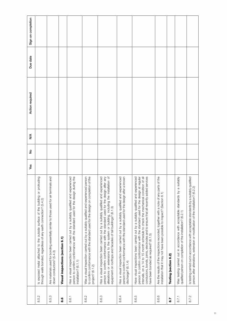
6.1 Visual inspection
Visual inspection should be carried out by a suitably qualified and
experienced person to confirm conformance with the standard
used for the design:
6.1.1 During installation.
6.1.2 On completion.
6.1.3 After any alterations or extensions to the system or building
including the installation of equipment on rooftops and
facades of tall buildings.
6.1.4 After a known discharge.
6.1.5 At regular intervals, on a 14 to 15 month schedule to check
the mechanical condition of all conductors, bonds, joints,
electrodes and to ensure that all recently added services
have been bonded as required.
The results of the inspections should be recorded, together with
a note of any parts of the installation that it may not have been
possible to inspect.
6.2 Testing
Testing should be carried out in accordance with acceptable
standards, for example BS 7430: 1998: Code of practice for
earthing (ref. 4), by a suitably qualified person. The resistance
to earth of each earth electrode, the resistance of the complete
earth termination system and the measurement of electrical
continuity of bonds and joints where necessary should be tested:
6.2.1 On completion of the installation.
6.2.2 After alterations, extension or modification.
6.2.3 After a known discharge.
7

6.2.4. On a regular schedule so that seasonal variations in
conditions are observed.
Full details of all tests should be recorded.
7. Developments in lightning protection
Existing reference information indicates that, over recent years,
most of the development regarding lightning protection has
centred around:
7.1 Improved standards and codes of practice
NFPA 780 (ref. 5) was last revised in 2000 and BS 6651 was
published in 1999 with two subsequent minor amendments. The
latter document was withdrawn in August 2008 and superseded
by BS EN 62305 (ref. 2).
In regard to developments in lightning protection technology,
BS 6651: 1999 (ref. 1) made the following statement.
‘The principle applying to all the provisions of this British Standard
(BS) is that of the “Faraday Cage” form of lightning protection. The
(BS) Technical Committee is aware of development and research
on other technologies in the field of lightning protection that has
been taking place in recent years, but it is the (BS) Committee’s
considered opinion that the materials, extent and dimensions
of the air terminations, down conductors, earth terminations,
bonding, components etc as laid down in this code of practice
be adhered to in full, irrespective of any devices or systems
employed which are claimed to provide enhanced protection.’
This view has not changed and applies equally well to BS EN 62305.
REFERENCES
1. BS 6651: 1999 Code of Practice for protection of structures
against lightning,BritishStandardsInstitution;(superseded
in August 2008).
2. BS EN 62305: 2006: Protection against lightning, (Parts 1
to 4), British Standards Institution.
3. Electricity at Work Regulations 1989, SI 1989 No. 635, The
Stationery Office.
4. BS 7430: 1998: Code of practice for earthing, British
Standards Institution, (replaced by revised edition).
5.NFPA 780: 2000;Standard for the installation of lightning
protection systems, National Fire Protection Association, USA.
FURTHER READING
Lightning Protection for Churches, Ecclesiastical Insurance
Group, 2000, English Heritage.
Palles-Clark, Peter, Advisory Notes, Lightning Protection,
2007, Diocesan Advisory Committee.
Other source of information
Association of Technical Lightning and Access Specialists (ATLAS)
Tel: 0115 955 8818
Fax: 0115 941 2238
Email: [email protected]
Web: www.atlas-1.org.uk
8

8.1
Gen
era
lYe
sN
oN
/AA
ctio
n re
qui
red
Due
dat
eS
ign
on
com
ple
tion
8.1.
1Is
the
need
for
prot
ectio
n se
lf-ev
iden
t? (F
or e
xam
ple
a bu
ildin
g w
here
larg
e nu
mbe
rs o
f peo
ple
cong
rega
te, s
igni
fican
t am
ount
s of
flam
mab
le o
r ex
plos
ive
mat
eria
ls a
re k
ept,
a ta
ll or
isol
ated
str
uctu
re, o
r a
build
ing
of h
isto
ric o
r cu
ltura
l im
port
ance
.) (S
ectio
n 3)
8.1.
2If
the
need
for
prot
ectio
n is
not
sel
f evi
dent
, has
a r
isk
asse
ssm
ent b
ased
on
B
S E
N 6
2305
or
othe
r ac
cept
able
met
hodo
logy
bee
n co
nduc
ted
by a
com
pete
nt
pers
on to
det
erm
ine
the
dire
ct a
nd s
econ
dary
effe
ct p
rote
ctio
n ne
eds?
(3.1
)
8.1.
3Is
the
syst
em d
esig
ned
in a
ccor
danc
e w
ith B
S E
N 6
2305
or
othe
r ac
cept
able
st
anda
rd w
ith p
artic
ular
refe
renc
e to
the
need
and
pla
cing
of a
ir te
rmin
atio
ns,
dow
n co
nduc
tors
, joi
nts,
bon
ding
to p
reve
nt s
ide
flash
ing,
test
poi
nts,
ear
th
term
inat
ions
and
ear
th e
lect
rode
s? (S
ectio
n 4)
8.1.
4A
re a
ll th
e lig
htni
ng p
rote
ctio
n pr
ovis
ions
inst
alle
d in
acc
orda
nce
with
the
desi
gn
requ
irem
ents
of B
S E
N 6
2305
or
othe
r ac
cept
able
sta
ndar
d? (S
ectio
n 5)
8.1.
5Is
sur
ge p
rote
ctio
n pr
ovid
ed w
here
requ
ired?
(Sec
tion
3)
8.2
Air
term
inati
on d
evi
ces
(secti
on 5
.1)
8.2.
1Isanypartoftheroofmorethan7.5mfrom
thenearesthorizontalconductor?(5.1.1)
8.2.
2Isagrid
networkofm
eshsizenogreaterthan15m
by15
minuseonlarge,
flat r
oofs
? (5
.1.2
)
8.2.
3A
re a
dditi
onal
con
duct
ors
prov
ided
on
mul
tiple
rid
ge ro
ofs
whe
re th
e di
stan
ce
betw
een
the
ridge
s re
nder
s th
em n
eces
sary
? (5
.1.3
)
8.2.
4Arealuminium,c
oppe
rorgalvanisedsteelstripsorro
dsofthecorrectsize
in
use
? (5
.1.4
)
8.2.
5A
re fi
cen
tres
for
solid
roun
d co
nduc
tors
that
are
use
d as
air
term
inat
ions
1m
apa
rt?
(Or
0.5m
apa
rt if
tape
or
stra
nded
con
duct
ors
are
used
.) (5
.1.5
)
8.3
Dow
n c
onducto
rs (se
cti
on 5
.2)
8.3.
1A
re c
ondu
ctor
s in
stal
led
sym
met
rical
ly a
roun
d th
e ou
tsid
e w
alls
of
the
stru
ctur
e,
star
ting
from
the
corn
ers?
(5.2
.1)
9
8.
Che
cklis
t

Yes
No
N/A
Act
ion
req
uire
dD
ue d
ate
Sig
n o
n co
mp
letio
n
8.3.
2D
o do
wn
cond
ucto
rs fo
llow
the
mos
t dire
ct p
ath
that
avo
ids
shar
p be
nds
or n
arro
w
loop
s? (5
.2.2
)
8.3.
3Is
a d
own
cond
ucto
r pro
vide
d fo
r eve
ry 1
5m o
f bui
ldin
g pe
rimet
er?
(The
per
imet
er o
f th
e bu
ildin
g he
re is
mea
sure
d at
roof
or g
roun
d le
vel,
whi
chev
er is
gre
ater
.) (5
.2.3
)
8.3.
4A
re a
t lea
st tw
o do
wn
cond
ucto
rs p
rovi
ded
for
tall
build
ings
whe
re te
stin
g an
d in
spec
tion
may
be
diffi
cult?
(5.2
.4)
8.3.
5A
re t
he c
ondu
ctor
s jo
ined
to
form
a F
arad
ay C
age?
(Thi
s re
duce
s th
e im
peda
nce
and
incr
ease
s th
e nu
mbe
r of
pat
hs fo
r a
disc
harg
e to
follo
w, a
nd s
o im
prov
es t
he
prot
ectio
n of
the
inte
rior
of th
e bu
ildin
g.) (
5.2.
5)
8.3.
6Is
use
mad
e of
the
met
al p
arts
of t
he s
truc
ture
suc
h as
ste
el fr
ames
, rei
nfor
cing
ba
rs a
nd s
teel
roof
s in
som
e ca
ses
as p
art o
f the
ligh
tnin
g pr
otec
tion
syst
em
(pro
vide
d th
at th
eir
elec
tric
al c
ontin
uity
can
be
assu
red)
? (5
.2.6
)
8.3.
7H
as i
t be
en r
emem
bere
d th
at t
he g
reat
er t
he n
umbe
r of
int
erco
nnec
ted
dow
n co
nduc
tors
pro
vide
d, th
e lo
wer
the
risk
of s
ide
flash
ing
occu
rrin
g? (5
.2.7
)
8.3.
8H
ave
suita
ble
mat
eria
ls b
een
used
in th
e in
stal
latio
n? (S
ee s
ectio
n 5.
1.4.
)
8.3.
9H
ave
the
cond
ucto
rs b
een
atta
ched
usi
ng th
e co
rrec
t fixi
ng c
entr
es?
(5.2
.9)
8.4
Eart
h t
erm
inati
on n
etw
ork
s (s
ecti
on 5
.3)
8.4.
1H
as a
com
bine
d re
sist
ance
to e
arth
of 1
0Ω o
r le
ss b
een
achi
eved
for
the
who
le o
f th
e ea
rth
term
inat
ion
netw
ork
(exc
ludi
ng b
ondi
ng to
oth
er s
ervi
ces)
? (5
.3.1
)
8.4.
2H
as e
ach
dow
n co
nduc
tor
been
pro
vide
d w
ith a
n ea
rth
term
inal
? (5
.3.2
)
8.4.
3H
as a
com
mon
ear
th te
rmin
atio
n ne
twor
k be
en p
rovi
ded
for t
he li
ghtn
ing
prot
ectio
n sy
stem
and
all
othe
r se
rvic
es?
(5.3
.3)
8.4.
4A
re s
uita
ble
prov
isio
ns fi
tted
to is
olat
e ea
rth
term
inal
s fo
r tes
ting
purp
oses
? (5
.3.4
)
8.4.
5A
re e
arth
ele
ctro
des
and
cond
ucto
rs o
f the
cor
rect
dim
ensi
ons?
(5.3
.5)
8.5
Bon
din
g (se
cti
on 5
.4)
8.5.
1Is
all
met
al fo
rmin
g pa
rts
of th
e bu
ildin
g bo
nded
, inc
ludi
ng u
tility
ser
vice
s in
con
tact
w
ith th
e gr
ound
? (5
.4.1
)
10
Yes
No
N/A
Act
ion
req
uire
dD
ue d
ate
Sig
n o
n co
mp
letio
n
8.5.
2Is
exp
osed
met
al a
ttac
hed
to t
he o
utsi
de s
urfa
ce o
f th
e bu
ildin
g or
pro
trud
ing
thro
ugh
wal
ls b
onde
d, re
gard
less
of a
ny e
arth
con
nect
ion?
(5.4
.2)
8.5.
3A
re m
ater
ials
use
d fo
r bon
ding
ess
entia
lly s
imila
r to
thos
e us
ed fo
r air
term
inal
s an
d do
wn
cond
ucto
rs?
(5.4
.3)
8.6
Vis
ual in
specti
ons
(secti
on 6
.1)
8.6.
1H
as a
vis
ual i
nspe
ctio
n be
en c
arrie
d ou
t by
a s
uita
bly
qual
ified
and
exp
erie
nced
pe
rson
to
confi
rm c
onfo
rman
ce w
ith t
he s
tand
ard
used
for
the
des
ign
durin
g th
e in
stal
latio
n? (6
.1.1
)
8.6.
2W
as a
vis
ual i
nspe
ctio
n ca
rrie
d ou
t by
a s
uita
bly
qual
ified
and
exp
erie
nced
per
son
to c
onfir
m c
onfo
rman
ce w
ith th
e st
anda
rd u
sed
for t
he d
esig
n on
com
plet
ion
of th
e pr
ojec
t? (6
.1.2
)
8.6.
3H
as a
vis
ual i
nspe
ctio
n be
en c
arrie
d ou
t by
a s
uita
bly
qual
ified
and
exp
erie
nced
pe
rson
to
confi
rm c
onfo
rman
ce w
ith t
he s
tand
ard
used
for
the
des
ign
afte
r an
y al
tera
tions
or
exte
nsio
ns t
o th
e sy
stem
or
build
ing,
inc
ludi
ng t
he i
nsta
llatio
n of
eq
uipm
ent o
n ro
ofto
ps a
nd fa
cade
s of
tall
build
ings
? (6
.1.3
)
8.6.
4H
as a
vis
ual i
nspe
ctio
n be
en c
arrie
d ou
t by
a s
uita
bly
qual
ified
and
exp
erie
nced
pe
rson
to c
onfir
m c
onfo
rman
ce w
ith th
e st
anda
rd u
sed
for t
he d
esig
n af
ter a
kno
wn
disc
harg
e? (6
.1.4
)
8.6.
5H
ave
visu
al in
spec
tions
bee
n ca
rrie
d ou
t by
a s
uita
bly
qual
ified
and
exp
erie
nced
pe
rson
to
confi
rm c
onfo
rman
ce w
ith t
he s
tand
ard
used
for
the
des
ign
at r
egul
ar
inte
rval
s, o
n a
14 t
o 15
mon
th s
ched
ule
to c
heck
the
mec
hani
cal c
ondi
tion
of a
ll co
nduc
tors
, bon
ds, j
oint
s, e
lect
rode
s an
d to
ens
ure
that
all
rece
ntly
add
ed s
ervi
ces
have
bee
n bo
nded
as
requ
ired?
(6.1
.5)
8.6.
6A
re th
e re
sults
of t
he in
spec
tions
reco
rded
, tog
ethe
r with
a n
ote
of a
ny p
arts
of t
he
inst
alla
tion
that
it m
ay n
ot h
ave
been
pos
sibl
e to
insp
ect?
(Sec
tion
6.1)
8.7
Test
ing (se
cti
on 6
.2)
8.7.
1W
as t
estin
g ca
rrie
d ou
t in
acc
orda
nce
with
acc
epta
ble
stan
dard
s by
a s
uita
bly
qual
ified
per
son
on c
ompl
etio
n of
the
inst
alla
tion?
(6.2
.1)
8.7.
2Is
test
ing
carr
ied
out i
n ac
cord
ance
with
acc
epta
ble
stan
dard
s by
a s
uita
bly
qual
ified
pe
rson
afte
r al
tera
tions
, ext
ensi
on o
r m
odifi
catio
n of
the
inst
alla
tion?
(6.2
.2)
11

8.7.
3Is
tes
ting
carr
ied
out
in a
ccor
danc
e w
ith a
ccep
tabl
e st
anda
rds
by a
sui
tabl
y qu
alifi
ed p
erso
n af
ter
a kn
own
disc
harg
e? (6
.2.3
)
8.7.
4Is
tes
ting
carr
ied
out
in a
ccor
danc
e w
ith a
ccep
tabl
e st
anda
rds
by a
sui
tabl
y qu
alifi
ed p
erso
n on
a re
gula
r sc
hedu
le s
o th
at s
easo
nal v
aria
tions
in c
ondi
tions
are
ob
serv
ed?
(6.2
.4)
8.7.
5A
re fu
ll de
tails
of a
ll te
sts
reco
rded
? (s
ectio
n 6.
2)
Ad
dre
ssS
igna
ture
/ N
ame
Dat
e
12

13


administered by
Fire Protection AssociationLondon Road, Moreton in MarshGloucestershire GL56 0RH, UKTel: +44 (0)1608 812500 Fax: +44 (0)1608 812501 Email: [email protected] Website: www.riscauthority.co.uk
2009 © The Fire Protection Association on behalf of RISCAuthority
Hard copies of this document may be obtained from the publications department of the FPA at the above address.
Electronic copies may be obtained from www.riscauthority.co.uk.
Printed by: Information Press 04.09/0.8