
Variable displacement pump - Poclain Hydraulics : Locations · Variable displacement pump POCLAIN...
52
P90 VARIABLE DISPLACEMENT PUMP T E C H N I C A L C A T A L O G
Transcript of Variable displacement pump - Poclain Hydraulics : Locations · Variable displacement pump POCLAIN...

P 90V A R IA B LE D IS P LA C E M E N T P U M P
T E C H N I C A L C A T A L O G

Variable displacement pump POCLAIN HYDRAULICS
2 20/02/2017
Design
Features and options UnitFrame
055 075 100 130 180 250
Displacement cm³/rev[in³/rev.]
55 [3.35]
75 [4.58]
100 [6.10]
130 [7.91]
180 [10.98]
250 [15.25]
Flow at rated speed L/min[US gal/min]
215[57]
270[71]
330[87]
403[106]
468[124]
575[152]
Torque at maximum displacement N.m/bar[lbf.in/1000 PSI]
0.88[530]
1.19[730]
1.59[970]
2.07[1 260]
2.87[1 750]
3.97[2 433]
Mass moment of inertia of rotating component
kg.m²[slug.ft²]
0.0060[0.0044]
0.0096[0.0071]
0.0150[0.0111]
0.0230[0.0170]
0.0380[0.0280]
0.0650[0.0479]
Weight kg [lb] 40 [88] 49 [108] 68 [150] 88 [194] 136 [300] 154 [340]Mounting (per SAE J744) C C C D E ERotation Clockwise or Counterclockwise
Main ports: 4-bolt split-flange(per SAE J518 code 62)
mm[in]
25.4[1.0]
25.4[1.0]
25.4[1.0]
31.75[1.25]
38.1[1.5]
38.1[1.5]
Main port configuration Radial or axial Radial
Case drain ports (SAE O-ring boss) UNF thread (in.) 1.0625–12 1.0625–12 1.0625–12 1.625–12 1.625–12 1.625–12Other ports SAE O-ring boss.
Shafts Splined, straight keyed, and tapered shafts available.
Auxiliary mounting SAE SAE A, B, C SAE A, B, C, D SAE A, B, C, D, E
Installation positionInstallation is recommended with control on the top or side. Consult your representative for nonconformance guidelines. The housing must remain filled with hydraulic fluid.
Servo pistonServo armSlider block
Piston
Bushing
Cylinder block
Valve plate
Charge pump Swashplate Cradle guide
SlipperDisplacement control
Feedback linkage
Cradle bearing
Roller bearing
Shaft seal
Input shaf
Rear bearing

POCLAIN HYDRAULICS Variable displacement pump
20/02/2017 3
CONTENT
Syst
emde
sign
Par
a.M
odel
Cod
eO
pera
ting
Para
met
ers
Inst
alla
tion
Dra
win
gsI
SIZE
055
SIZE
250
Opt
ions
SIZE
075
SIZE
100
SIZE
130
SIZE
180
MODEL CODE 4
OPERATING PARAMETERS 9
SYSTEM DESIGN PARAMETERS 13
INSTALLATION DRAWINGS 17
FRAME SIZE 055 19
FRAME SIZE 075 23
FRAME SIZE 100 27
FRAME SIZE 130 29
FRAME SIZE 180 33
FRAME SIZE 250 37
OPTIONS 43

Variable displacement pump POCLAIN HYDRAULICS
4 20/02/2017
MODEL1
R
1 2
SIZE
3
M
ControlsSolenoide control with non contact 12V feedback sensor SA
Solenoide control with non contact 24V feedback senso* SB
High pressure regulationHigh pressure relief valves for port A and B 2
Auxiliary mounting padSAE-A with sealed cover, 9 teeth coupling ABSAE-BB with sealed cover, 15 teeth coupling BBSAE-B with sealed cover, 13 teeth coupling BCSAE-C with sealed cover, 4 bolt adapter, 14 teeth coupling, (2)1/2-13 UNC CD
SAE-D with sealed cover, 13 teeth coupling DESAE-D with sealed cover, 27 teeth coupling DGSAE-E with sealed cover, 13 teeth coupling EFNo auxiliary mounting pad NN
Endcap portsSide ports 60Twin ports 80
FiltrationExternal charge pump DPressure integral (long filter) LPressure integral (short filter) PRemote pressure RRemote pressure with SAE 1 1/16 thread ports for high flow T
Suction filtration S
RotationClockwise RCounter clockwise L
Displacement55 [3.35] 05575 [4.58] 075100 [6.10] 100130 [7.91] 130180 [10.98] 180250 [15.25] 250
cm³/rev. [in³/rev.]
1 2 1
N
1
P
9 01 2
J
1 2
G
1 2
* Not compatible with SD Master andSD Premier ECU.
MODEL CODE

POCLAIN HYDRAULICS Variable displacement pump
20/02/2017 5
Syst
emde
sign
Par
a.M
odel
Cod
eO
pera
ting
Para
met
ers
Inst
alla
tion
Dra
win
gsI
SIZE
055
SIZE
250
Opt
ions
SIZE
075
SIZE
100
SIZE
130
SIZE
180
CODE
Displacement limitationNo limiters, only for 180 CNo limiters 3
1
H
1 2
W
3
Y
Ports(A) Servo (B) ServoWithout restrictor 33Restrictor 0,8 mm [0.031 in] A4Restrictor 1 mm [0.039 in] P1
Charging systemCharge pump displacement 11 [0.67] BCharge pump displacement 14 [0.85] CCharge pump displacement 17 [1.03] DCharge pump displacement 20 [1.22] ECharge pump displacement 26 [1.58] FCharge pump displacement 34 [2.07] HCharge pump displacement 47 [2.86] JCharge pump displacement 65 [3.96] KExternal charge pump with internal charge pressure relief valve with auxiliary mounting pad L
External charge pump with internal charge pressure relief valve without auxiliary mounting pad N
Special hardware features
PGA CP15 + 0.5° valve plate and Poclain Hydraulics name tag
PEA CP15 + 0.5° valve plate, speed sensor KPPG156 and Poclain Hydraulics name tag
PGB CP30 + 4.3° valve plate (low noise) and Poclain Hydraulics name tag
PEB CP30 + 4.3° valve plate (low noise), speed sensor KPPG 156 and Poclain Hydraulics name tag
PGC CP150 + 1.5°; additional springs on swash plate return to neutral and Poclain Hydraulics name tag
PECCP150 + 1.5°; additional springs on swash plate return to neutral and Poclain Hydraulics name tag with a speed sensor KPPG156
Charge pressure setting20 bar [290 PSI] 2022 bar [319 PSI] 2224 bar [348 PSI] 2426 bar [377 PSI] 2628 bar [406 PSI] 2830 bar [435 PSI] 3032 bar [464 PSI] 32
High pressure (Y: Setting A, Z: Setting B)
26 260 bar [3770 PSI]32 320 bar [4641 PSI]35 350 bar [5076 PSI]38 380 bar [5511 PSI]40 400 bar [5801 PSI]42 420 bar [6091 PSI]
Shaft optionsSplined shaft, 21 teeth, pitch = 16/32 C6Splined shaft, 23 teeth, pitch = 16/32 C7Splined shaft, 27 teeth, pitch = 16/32 C8Splined shaft, 13 teeth, pitch = 8/16 F1Splined shaft, 14 teeth, pitch = 12/24 S1
cm³/rev. [in³/rev.]
1 21
F L
1 2
Z
1 2
K
1 2
T
1 2

Variable displacement pump POCLAIN HYDRAULICS
6 20/02/2017
Possible configurations Standard ------------------- Not available
Rotation (R1)Option Description 055 075 100 130 180 250R ClockwiseL Counter clockwise
Controls (M)Option Description 055 075 100 130 180 250SA Solenoid control 12V with non contact feedback sensorSB Solenoid control 24V with non contact feedback sensor
High pressure regulation (P)Option Description 055 075 100 130 180 2502 High pressure relief valves for port A and B
Auxiliary mounting pad (J)Option Description 055 075 100 130 180 250AB SAE-A with sealed cover, 9 teeth couplingBB SAE-BB with sealed cover, 15 teeth couplingBC SAE-B with sealed cover, 13 teeth coupling
CD SAE-C with sealed cover, 4 bolt adapter, 14 teeth coupling, (2)1/2-13 UNC
DE SAE-D with sealed cover, 13 teeth coupling - - -DG SAE-D with sealed cover, 27 teeth coupling - - -EF SAE-E with sealed cover, 13 teeth coupling - - - -NN No auxiliary mounting pad
Endcap ports (G)Option Description 055 075 100 130 180 25060 Side ports - - -80 Twin ports
Filtration (N)Option Description 055 075 100 130 180 250D External charge pump -L Pressure integral (long filter) - -P Pressure integral (short filter) - -R Remote pressure - -
T Remote pressure with SAE 1 1/16 thread ports for high flow - - - -
S Suction filtration
Displacement limitation (F)Option Description 055 075 100 130 180 250C No limiters, only for 180 - - - - -3 No limiters -
Shaft optionsOption Description 055 075 100 130 180 250C6 Splined shaft, 21 teeth, pitch = 16/32 - - -C7 Splined shaft, 23 teeth, pitch = 16/32 - - - -C8 Splined shaft, 27 teeth, pitch = 16/32Splined shaft, 27 teeth, pitch = 16/32 - - -F1 Splined shaft, 13 teeth, pitch = 8/16Splined shaft, 13 teeth, pitch = 8/16 - -S1 Splined shaft, 14 teeth, pitch = 12/24 - - -

POCLAIN HYDRAULICS Variable displacement pump
20/02/2017 7
Syst
emde
sign
Par
a.M
odel
Cod
eO
pera
ting
Para
met
ers
Inst
alla
tion
Dra
win
gsI
SIZE
055
SIZE
250
Opt
ions
SIZE
075
SIZE
100
SIZE
130
SIZE
180
Standard ------------------- Not availableCharging system (H)
Option Description 055 075 100 130 180 250B Charge pump displacement 11 [0.67] - - - - -C Charge pump displacement 14 [0.85] - - - -D Charge pump displacement 17 [1.03] - - -E Charge pump displacement 20 [1.22] - - - -F Charge pump displacement 26 [1.58] - - - -H Charge pump displacement 34 [2.07] - - - -J Charge pump displacement 47 [2.86] - - - -K Charge pump displacement 65 [3.96] - - - - -L External charge pump with internal charge pressure relief valve -
N External charge pump with internal charge pressure relief valve for units with no auxiliary mounting pad - -
Restrictors (T)Option Ports 055 075 100 130 180 250
-- --- ---- -(A) servo --------------(B) servo -------------33 Without restrictorsA4 Restrictor 0,8 mm [0.031 in]P1 Restrictor 1 mm [0.039 in]
Special hardwre features (W)Option Description 055 075 100 130 180 250PGA CP15 + 0,5° valve plate and Poclain Hydraulics name tag -
PEA CP15 + 0,5° valve plate and Poclain Hydraulics name tagwith a speed sensor KPPG156 -
PGB CP30 + 4,3° and Poclain Hydraulics name tag (Low noise) - - - -
PEB CP30 + 4,3° and Poclain Hydraulics name tag with speed sensor KPPG 156 (Low noise) - - - -
PGC CP150 + 1.5°; additional springs on swash plate return to neutral and Poclain Hydraulics name tag - - - - -
PEC CP150 + 1.5°; additional springs on swash plate return to neutral and Poclain Hydraulics name tag with a speed sensor KPPG156 - - - - -
High pressure (Y: setting A; Z: setting B)Option Description 055 075 100 130 180 25026 260 bar32 320 bar35 350 bar38 380 bar40 400 bar42 420 bar
Charge pressure setting (K)Option Description 055 075 100 130 180 25020 20 bar22 22 bar24 24 bar26 26 bar28 28 bar30 30 bar32 32 bar
cm³/rev. [in³/rev.]

8 20/02/2017
Variable displacement pump POCLAIN HYDRAULICS
Methodology :This document is intended for manufacturers of machines that incorporate Poclain Hydraulics products. It describes the technical characteristics of Poclain Hydraulics products and specifies installation conditions that will ensure optimum operation. This document includes important comments concerning safety. They are indicated in the following way:
This document also includes essential operating instructions for the product and general information. These are indicated in the following way:
The views in this document are created using metric standards. The dimensional data is given in mm and in inches (inches are between brackets and italic)
Safety comment.
Essential instructions.
General information .
Information on the model code.
Weight of component without oil.
Volume of oil.
Units.
Tightening torque.
Screws.
Information intended for Poclain-Hydraulics personnel.

POCLAIN HYDRAULICS Variable displacement pump
20/02/2017 9
Syst
emde
sign
Par
a.M
odel
Cod
eO
pera
ting
Para
met
ers
Inst
alla
tion
Dra
win
gsSI
ZE 0
55SI
ZE 2
50O
ptio
nsSI
ZE 0
75SI
ZE 1
00SI
ZE 1
30SI
ZE 1
80
OPERATING PARAMETERS
OverviewsMaintain operating parameters within prescribed limits during all operating conditions. This section defines operating limits given in the table Operating parameters.
Input speedMinimum speed is the lowest input speed recommended during engine idle condition. Operating below minimum speed limits the pump’s ability to maintain adequate flow for lubrication and power transmission.
Continuous speed is the highest input speed recommended at full power condition. Operating at or below this speed should yield satisfactory product life.
Maximum speed is the highest operating speed permitted. Exceeding maximum speed reduces product life and can cause loss of hydrostatic power and braking capacity. Never exceed the maximum speed limit under any operating conditions.
System pressureSystem pressure is the differential pressure between system ports A and B. It is the dominant operating variable affecting hydraulic unit life. High system pressure, which results from high load, reduces expected life. System pressure must remain at or below continuous pressure during normal operation to achieve expected life.
Continuous pressure is the average, regularly occurring operating pressure. Operating at or below this pressure should yield satisfactory product life.
Maximum pressure is the highest intermittent pressure allowed. Maximum machine load should never exceed this pressure. For all applications, the load should move below this pressure.
Operating parameters UnitFrame size
055 075 100 130 180 250Input speedMinimum
min-1(rpm)500
Continuous 3900 3600 3300 3100 2600 2300Maximum 4250 3950 3650 3400 2850 2500
System pressureRated
bar [PSI]
420 [6000]
Maximum 480 [7000]
Minimum low loop 10 [145]
Inlet pressure (charge inlet)Minimum (continuous) bar (abs.)
[in. Hg vac.]0.7 [9]
Minimum (cold start) 0.2 [24]
Case pressureContinuous bar [PSI]
3 [43]
Maximum (cold start) 5 [73]
Exceeding maximum speed may cause a loss of hydrostatic drive line power and braking capacity. You must provide a braking system, redundant to the hydrostatic transmission, sufficient to stop and hold the vehicle or machine in the event of hydrostatic drive power loss.
All pressure limits are differential pressures referenced to low loop (charge) pressure. Substract low loop pressure from gauge readings to compute the differential.

Variable displacement pump POCLAIN HYDRAULICS
10 20/02/2017
Case pressureUnder normal operating conditions, the maximum continuous case pressure must not exceed 3 bar [44 PSI]. Maximum allowable intermittent case pressure during cold start must not exceed 5 bar [73 PSI]. Size drain plumbing accordingly.
Hydraulic Fluids
Operation with case pressure in excess of these limits may damage seals, gaskets, and/or housings, causing external leakage. Performance may also be affected since charge and system pressure are additive to case pressure.
Fluid specificationsViscosity Unit Minimum
mm²/sec (cSt) [SUS]
7 [49]
Continuous 12-80 [70-370]
Maximum 1600 [7500]
Temperature UnitMinimum
°C [°F]
-40 [-40]
Continuous 104 [220]
Maximum 115 [240]
FiltrationCleanliness 18/13 or better per ISO 4406
Efficiency (suction filtration) 35-45=75 ( 10 2)
Efficiency (charge filtration) 15-20=75 ( 10 10)
Recommended inlet screen size 100-125 m [0.0039-0.0049 in]
General RecommendationsPoclain hydraulics recommends the use of hydraulic fluids defined by the ISO 15380 and ISO 6743-4 standards.For temperate climates, the following types are recommended.• HM 46 or HM 48 for fixed installations.• HV 46 or HV 68 for mobile installations.• HEES 46 for mobile installations.
These specifications correspond to category 91H of the CETOP standard, parts 1, 2 and 3 of the DIN 51524 standard, and grades VG32, VG 46 and VG68 of the ISO 6743-4 standards.
It is also possible to use ATF, HD, HFB, HFC or HFD type hydraulic fluid upon Poclain Hydraulics specific approval of the components’ operating conditions.
Standardized designations for the fluids• HM : Mineral fluids having specific antioxidant, anticorrosion and antiwear properties (HLP equivalent to DIN
51524 parts 1 and 2).• HV : HM mineral fluids providing improved temperature and viscosity properties (DIN 51524 part 3).• HEES :Biodegradable fluids based on organic esters.It is also possible to use a fluid that meets the biodegradability criteria and is compatible in the event of accidental food contact. The BIOHYDRAN FG 46 fluid designed by the company Total has undergone testing of its properties and performance on our test benches. Since this type of fluid has not yet been categorized, it is the responsibility of machine manufacturers to validate its compatibility with all of the components used in order to guarantee that the intended functions will be fulfilled (specifically the brakes' hold on a slope and emergency braking) and this for the desired life time of all equipment items.
Class32 (ISO VG 32) : Viscosity of 32 cSt at 40°C.Class46 (ISO VG 46) : Viscosity of 46 cSt at 40°C.Class68 (ISO VG 68) : Viscosity of 68 cSt at 40°C.
During operation, the temperature of the motors must be between 0°C [32°F] and 80°C [176°F]; the minimum and maximum temperatures may be exceeded momentarily by ± 20°C [± 68°F] for a duration of less than 30 minutes.For all applications outside these limits, please consult with your Poclain Hydraulics’ application engineer.
For biodegradable fluids, consult your Poclain Hydraulics’ application engineer

POCLAIN HYDRAULICS Variable displacement pump
20/02/2017 11
Syst
emde
sign
Par
a.M
odel
Cod
eO
pera
ting
Para
met
ers
Inst
alla
tion
Dra
win
gsSI
ZE 0
55SI
ZE 2
50O
ptio
nsSI
ZE 0
75SI
ZE 1
00SI
ZE 1
30SI
ZE 1
80
Efficiency
Pump performance as a function of operating speedThe figure below shows typical overall and volumetric efficiencies for P90 pumps with system pressures of 210 and 420 bar [3000 and 6000 PSI], speed as percent of rated speed, and a fluid viscosity of 8 mm2/s (cSt) [50 SUS].
Rendement global et rendement volumétrique à la cylindrée maximaleOverall efficiency ( t) and volumetric efficiency ( v) at maximum displacement
Pump performance as a function of pressure and speedThe following performance maps show typical overall efficiencies for P90 pumps with system pressures from 70 to 420 bar [1 000 to 6 000 PSI] at 2/3 of rated speed varying between 1/4 to maximum displacement. These efficiency maps apply to all frame sizes.
Effi
cien
cy %
Speed % of rated continuous speed
Overall efficiency at maximum displacement Pump overall ( t) efficiency at 2/3 rated speed
Speed % of rated continuous speed
Sys
tem
pre
ssur
eP
SI
Percent of maximum displacement
PS
I
bar
bar

Variable displacement pump POCLAIN HYDRAULICS
12 20/02/2017

POCLAIN HYDRAULICS Variable displacement pump
20/02/2017 13
Syst
emde
sign
Par
a.M
odel
Cod
eO
pera
ting
Para
met
ers
Inst
alla
tion
Dra
win
gsSI
ZE 0
55SI
ZE 2
50O
ptio
nsSI
ZE 0
75SI
ZE 1
00SI
ZE 1
30SI
ZE 1
80
SYSTEM DESIGN PARAMETERSFluid and filtrationTo prevent premature wear, it is imperative that only clean fluid enter the hydrostatic transmission circuit. A filter capable of controlling the fluid cleanliness to ISO 4406 class 22/18/13 (SAE J1165) or better under normal operating conditions is recommended.
The filter may be located either on the inlet (suction filtration) or discharge (charge pressure filtration) side of the charge pump. The selection of a filter depends on a number of factors including the contaminant ingression rate, the generation of contaminants in the system, the required fluid cleanliness, and the desired maintenance interval. Filters are selected to meet the above requirements using rating parameters of efficiency and capacity.
Filter efficiency may be measured with a Beta ratio1 ( X). For simple suction-filtered closed circuit transmissions and open circuit transmissions with return line filtration, a filter with a -ratio within the range of 35-45 = 75 ( 10 2) or better has been found to be satisfactory. For some open circuit systems, and closed circuits with cylinders being supplied from the same reservoir, a considerably higher filter efficiency is recommended. This also applies to systems with gears or clutches using a common reservoir. For these systems, a charge pressure or return filtration system with a filter -ratio in the range of 15-20 = 75 ( 10 10) or better is typically required.
Because each system is unique, only a thorough testing and evaluation program can fully validate the filtration system.
Charge pressureThe charge pressure setting listed in the model code is based on the charge flow across the charge pressure relief valve at fluid temperature of 50 °C [120 °F].
Independent braking system
ReservoirThe reservoir should be designed to accommodate maximum volume changes during all system operating modes and to promote de-aeration of the fluid as it passes through the tank.
A suggested minimum total reservoir volume is 5/8 of the maximum charge pump flow per minute with a minimum fluid volume equal to 1/2 of the maximum charge pump flow per minute. This allows 30 seconds fluid dwell for removing entrained air at the maximum return flow. This is usually adequate to allow for a closed reservoir (no breather) in most applications.
Locate the reservoir outlet (charge pump inlet) above the bottom of the reservoir to take advantage of gravity separation and prevent large foreign particles from entering the charge inlet line. A 125 μm screen over the outlet port is recommended. Position the reservoir inlet (fluid return) to discharge below the normal fluid level, toward the interior of the tank. A baffle (or baffles) will further promote de-aeration and reduce surging of the fluid.
1 Filter x-ratio is a measure of filter efficiency defined by ISO 4572. It is defined as the ratio of the number of particles greater than a given diameter (“x” in microns) upstream of the filter to the number of these particles.
The loss of hydrostatic drive line power, in any mode of operation (forward, neutral, or reverse) may cause the system to lose hydrostatic braking capacity. You must provide a braking system, redundant to the hydrostatic transmission, sufficient to stop and hold the vehicle or machine in the event of hydrostatic drive power loss.

Variable displacement pump POCLAIN HYDRAULICS
14 20/02/2017
Case drainA case drain line must be connected to one of the case outlets (L1 or L2) to return internal leakage to the system reservoir. The higher of the two case outlets should be used to promote complete filling of the case. Since case drain fluid is typically the hottest fluid in the system, it is advantageous to return this flow through the heat exchanger.
Sizing equationsThe following equations are helpful when sizing hydraulic pumps. Generally, the sizing process is initiated by an evaluation of the machine system to determine the required motor speed and torque to perform the necessary work function. First, the motor is sized to transmit the maximum required torque. The pump is then selected as a flow source to achieve the maximum motor speed.
SI units
Output flow Q = (l/min) Vg = Displacement per revolution(cm3/tr)
Input torque M = (N.m) p = po - pi (system pressure)(bar)
Input power P = = (kW)
nvmt
== = =
Speed (tr/mn)Volumetric efficiencyMechanical efficiencyOverall efficiency ( v. m)
US units
Output flow Q = (US gal/min) Vg = Displacement per revolution(in3/rev)
Input torque M = (lbf.in) p = po - pi (system pressure)(bar)
Input power P = = (hp)
nvmt
== = =
Speed (rpm)Volumetric efficiency Mechanical efficiency Overall efficiency ( v. m)
Vg.n. v1000
Vg. p20. . m
M. n.30 000
Q. p600. t
Vg.n. v231
Vg. p2. . m
M.n.198 000
Q. p1714. t

POCLAIN HYDRAULICS Variable displacement pump
20/02/2017 15
Syst
emde
sign
Par
a.M
odel
Cod
eO
pera
ting
Para
met
ers
Inst
alla
tion
Dra
win
gsSI
ZE 0
55SI
ZE 2
50O
ptio
nsSI
ZE 0
75SI
ZE 1
00SI
ZE 1
30SI
ZE 1
80
Shaft LoadsNormal bearing life in B10 hours is shown in the table below. The figures reflect a continuous differential pressure of 240 bar [3500 PSI], 1800 min-1 (rpm) shaft speed, maximum displacement, and no external shaft side load. The data is based on a 50% forward, 50% reverse duty cycle, standard charge pump size, and standard charge pressure.
P90 pumps are designed with bearings that can accept external radial and thrust loads. The external radial shaft load limits are a function of the load position and orientation, and the operating conditions of the unit.
The maximum allowable radial load (Re), is based on the maximum external moment (Me), and the distance (L) from the mounting flange to the load. It may be determined using the table and formula below. Thrust (axial) load limits are also shown.
Re = Me / L
All external shaft loads affect bearing life. In applications with external shaft loads, minimize the impact by positioning the load at 90° or 270° as shown in the figure.
Contact your Poclain Hydraulics representative for an evaluation of unit bearing life if:• continuously applied external loads exceed 25 % of the maximum allowable radial load (Re).• the pump swashplate is positioned on one side of center all or most of the time.• the unit bearing life (B10) is critical.
Radial and thrust load position
Bearing life
Frame size Bearing life – B10 hrs055 22 090075 22 970100 22 670130 17 990180 16 150250 12 020
Allowable external shaft load
ParameterFrame size
055 075 100 130 180 250External moment (Me)N.m [lbf.in]
101[893]
118[1044]
126[1115]
140[1239]
161[1425]
176[1557]
Maximum shaft thrust in (Tin)N [lbf]
3340[750]
4300[966]
5160[1160]
5270[1184]
7000[1573]
7826[1759]
Maximum shaft thrust out (Tout)N [lbf]
910[204]
930[209]
1000[224]
688[154]
1180[265]
1693[380]
Pump swashplate
90°Re
270°Re
0° Re
180° Re
L
Tout
Re
Tin

Variable displacement pump POCLAIN HYDRAULICS
16 20/02/2017

POCLAIN HYDRAULICS Variable displacement pump
20/02/2017 17
Syst
emde
sign
Par
a.M
odel
Cod
eO
pera
ting
Para
met
ers
Inst
alla
tion
Dra
win
gsSI
ZE 0
55SI
ZE 2
50O
ptio
nsSI
ZE 0
75SI
ZE 1
00SI
ZE 1
30SI
ZE 1
80
INSTALLATION DRAWINGS
S1S2
SB1
SB2
M4
M5
L1 L2S M2
A
M3
B
M1A B
P T
Vbp
Ports size
PortsFrame size
055 075 100 130 180 250
A and B 1’’0flange SAE J518 code 62 1’’-1/4 flange SAE J518 code 62 1’’-1/2 flange SAE J518 code 62
S 1-5/16 - 12 UN 2B 1-5/8 - 12 UN 2B 1’’-1/2 flange SAE J518 code 61
L1 and L2 1’’-1/16 - 12 UN 2B 1’’-5/16 - 12 UN 2B 1’’-5/8 - 12 UN 2B
M1, M2 and M3 9/16’’ - 18 UNF 2B
M4 and M5 7/16’’ - 20 UNF 2B 9/16’’ - 18 UNF 2B
A et B : Main system of the loop (input / output)S : charge (feed) inletL1 and L2 : case drainM1 and M2 : A and B ports pressure gaugeM3 : charge (feed) pressure gaugeM4 and M5 : control pressure gauge
By-pass Valve :KV-4/2-3KO-6-1B-12DC(P/N 4012554)
By-pass valve (Vbp)and restrictors are in option
In case of electronic failure:The valve is not powered.
The pump is able to return to its neutral position slowly to avoid machine jerk.
During normal operating or shifting:The valve is powered.
The pump has a very short response time to allow soft shifting of Poclain Hydraulics motors.
Orifices are by passed to bring maximum flow directly to the servo cylinders.
Pump

Variable displacement pump POCLAIN HYDRAULICS
18 20/02/2017
Features :
Proportional electronic control driven by the Poclain Hydraulics electronic boxes.• Our electronic control boxes control the displacement and the direction of the flow while monitoring permanently the functioning parameters of
the engine and of the complete hydraulic system.• Two contamination resistant (IP65) solenoid valves controls the displacement and the direction of the flow.• A sensor linked to the swash plate monitors permanently the actual displacement setting.
Hydraulic symbol :
SA or SB control
Pump displacement Feedback angle for max displacement
055 19.2°075 16.4°100 19.1°130 17.4°
180/250 19.5°
- Mating connector: 007142212Z- Supply voltage: 5V DC max.
- Mating connector: 007142211X*- Supply voltage: 12 V DC max. (SA control)
24 V DC max. (SB control)- Intensity: 1.750 A max. (SA control)
0.875 A max. (SB control)
Shaft rotationClockwise counter clockwise
Actuated solenoid S1 S2 S1 S2Servo cylinder M5 M4 M5 M4Port A flow outlet inlet inlet outletPort B flow inlet outlet outlet inlet
Control (pump size 055) Control (pump size from 075 to 250)
Position sensor
Position sensorC +5VB SignalA Ground
For SD Master and SD Premier ECU use SA control whatever the supply voltage (12V or 24V).
*DIN 43650-A must be without integrated diode.

POCLAIN HYDRAULICS Variable displacement pump
20/02/2017 19
Syst
emde
sign
Par
a.M
odel
Cod
eO
pera
ting
Para
met
ers
Inst
alla
tion
Dra
win
gsSI
ZE 0
55SI
ZE 2
50O
ptio
nsSI
ZE 0
75SI
ZE 1
00SI
ZE 1
30SI
ZE 1
80
Control SA or SB, Side ports
Gauge port M2system pressure B9/16-18UNF-2B
Coupling may not protrude beyond this surface
Length of full spline
Port L1case drain use highest port as outlet1-1/16-12UN-2B
Shaft spline data:Pitch diameter = 29.633 [1.1667]Pressure angle = 30°Number of teeth = 14Pitch = 12/24ANSI B92.1-1970, class 5,fillet root side fit
Splined shaft option S1
Port L2case drain
1-1/16-12UN-2B
Approximatecenter of gravity
Gauge port M4servo pressure7/16-20UNF-2B
Coupling may notprotrude beyondthis surface
Length of full spline
Approximatecenter of
gravityGauge port M1system pressure A9/16-18UNF-2B
View "Z"
View "Y" View "X"
High pressurerelief valve
Shaft spline data: :Pitch diameter= 33.338 [1.3125]Pressure angle = 30°Number of teeth= 21Pitch = 16/32ANSI B92.1-1970, class 5,Fillet Root side fit
Splined shaft option C6
High pressurerelief valve
Port S: Charge pumpinlet
1-5/16-12UN-2B
Charge pressure relief valve
Ports A and B1.00 - 6000 psisplit flange boss per SAE J518 (Code 62)7/16-14UNC-2Bexcept 21 [0.83] minimum full thread
Gauge port M5 Servo pressure7/16-20UNF-2B
Gauge port M3charge pressure9/16-18UNF-2B
FRAME SIZE 055

Variable displacement pump POCLAIN HYDRAULICS
20 20/02/2017
Control SA or SB, Twin ports
Gauge port M2system pressure B9/16-18UNF-2B
Ports A and B1 - 6000 psi
split flange boss perSAE J518 (code 62)
7/16-14UNC-2B21 [0.83] minimum
full thread
Gauge port M1: system pressure A9/16-18UNF-2B
View "Y"
Port S: chargepump inlet
1-5/16-12UN-2B
port
S

POCLAIN HYDRAULICS Variable displacement pump
20/02/2017 21
Syst
emde
sign
Par
a.M
odel
Cod
eO
pera
ting
Para
met
ers
Inst
alla
tion
Dra
win
gsSI
ZE 0
55SI
ZE 2
50O
ptio
nsSI
ZE 0
75SI
ZE 1
00SI
ZE 1
30SI
ZE 1
80
SAE A (option AB), Side ports
SAE B (option BC), Side ports
See table in page 41 for O-ring size.
"X"
View "X"
4 threads3/8-16UNC-2B17 [0.67] deep
Coupling spline data:Pitch diameter = 14.288 [0.5625]Pressure angle = 30°Number of teeth = 9Pitch = 16/32ANSI B92.1-1970, class 6,fillet root side fitLength of spline = 37.13 [1.46]
"X"
View "X"
4 threads1/2-13UNC-2B22.8 [0.89] deep
Coupling spline data:Pitch diameter = 20.6375 [0.8125]Pressure angle = 30°Number of teeth = 13Pitch = 16/32ANSI B92.1-1970, class 6,fillet root side fitLength of spline = 29.51 [1.16]
See table in page 41 for O-ring size.

Variable displacement pump POCLAIN HYDRAULICS
22 20/02/2017
SAE C (option CD), Side ports
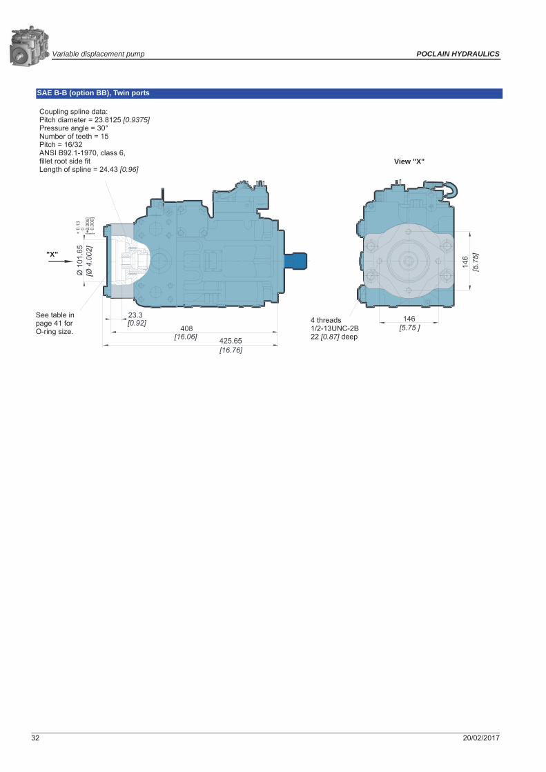
SAE B-B (option BB), Side ports
"X"
View "X"
4 threads1/2-13UNC-2B22 [0.87] deep
Coupling spline data:Pitch diameter = 29.6333 [1.167]Pressure angle = 30°Number of teeth = 14Pitch = 12/24ANSI B92.1-1970, class 6,fillet root side fitLength of spline = 18.97 [0.747]
See table in page 41 for O-ring size.
"X"
View "X"
4 threads1/2-13UNC-2B22 [0.87] deep
Coupling spline data: :Pitch diameter = 23.8125 [0.9375]Pressure angle = 30°Number of teeth = 15Pitch = 16/32ANSI B92.1-1970, class 6,fillet root side fitLength of spline = 24.43 [0.96]
See table in page 41 for O-ring size.

POCLAIN HYDRAULICS Variable displacement pump
20/02/2017 23
Syst
emde
sign
Par
a.M
odel
Cod
eO
pera
ting
Para
met
ers
Inst
alla
tion
Dra
win
gsSI
ZE 0
55SI
ZE 2
50O
ptio
nsSI
ZE 0
75SI
ZE 1
00SI
ZE 1
30SI
ZE 1
80
Control SA or SB, Side ports
127 0 -0
,05
[ 5
]
0 -0,0
02
Gauge port M2system pressure B
9/16-18UNF-2B
Coupling may not protrude beyond this surface
Length of full spline
Shaft spline data: :Pitch diameter = 29.633 [1.1667]Pressure angle = 30°Number of teeth = 14Pitch = 12/24ANSI B92.1-1970, class 5,fillet root side fit
Splined shaft option S1
Port L2 case drain1-1/16-12UN-2B
Approximatecenter of gravity
Gauge port M4servo pressure9/16-18UNF-2B
Coupling may notprotrude beyondthis surface
Length of full spline
Approximatecenter of
gravity
Gauge port M1system
pressure A9/16-18UNF-2B
View "Z"
View "Y" View "X"
High pressurerelief valve
Gauge port M3charge pressure9/16-18UNF-2B
Shaft spline data: :Pitch diameter = 36.513 [1.4375]Pressure angle = 30°Number of teeth = 23Pitch = 16/32ANSI B92.1-1970, class 5,Fillet Root side fit
Splined shaft option C7
High pressurerelief valve
Port S: Charge pump inlet1-5/16-12UN-2B
Charge pressure relief valve
Ports A and B1 - 6000 psisplit flange boss per SAE J518 (Code 62)7/16-14UNC-2Bminimum full thread
Gauge port M5servo pressure9/16-18UNF-2B
Port L1case drain use highest port as outlet1-1/16-12UN-2B
FRAME SIZE 075

Variable displacement pump POCLAIN HYDRAULICS
24 20/02/2017
Control SA or SB, Twin ports
Ports A and B1 – 6000 psi
split flange bossper SAE J518
(Code 62)7/16-14UNC-2B
except 20.8 [0.82]minimum full thread
Gauge port M1: system pressure A9/16-18UNF-2B
View "Y"
Port S: chargepump inlet
1-5/16-12UN-2B
Gauge port M2system pressure B
9/16-18UNF-2B

POCLAIN HYDRAULICS Variable displacement pump
20/02/2017 25
Syst
emde
sign
Par
a.M
odel
Cod
eO
pera
ting
Para
met
ers
Inst
alla
tion
Dra
win
gsSI
ZE 0
55SI
ZE 2
50O
ptio
nsSI
ZE 0
75SI
ZE 1
00SI
ZE 1
30SI
ZE 1
80
SAE A (option AB), Side ports
SAE B (option BC), Side ports
"X"
View "X"
4 threads3/8-16UNC-2B17 [0.67] deep
Coupling spline data: :Pitch diameter = 14.288 [0.5625]Pressure angle = 30°Number of teeth = 9Pitch = 16/32ANSI B92.1-1970, class 6,fillet root side fitLength of spline = 37.13 [1.46]
See table in page 41 for O-ring size.
"X"
View "X"
4 threads1/2-13UNC-2B22 [0.87] deep
Coupling spline data: :Pitch diameter = 20.6375 [0.8125]Pressure angle = 30°Number of teeth = 13Pitch = 16/32ANSI B92.1-1970, class 6,fillet root side fitLength of spline = 29.51 [1.16]
See table in page 41 for O-ring size.

Variable displacement pump POCLAIN HYDRAULICS
26 20/02/2017
SAE C (option CD), Side ports
SAE B-B (option BB), side ports
Coupling spline data:Pitch diameter = 29.6333 [1.167]Pressure angle = 30°Number of teeth = 14Pitch = 12/24ANSI B92.1-1970, class 6,fillet root side fitLength of spline = 18.97 [0.747]
"X"
View "X"
6 threads1/2-13UNC-2B22 [0.87] deep
See table in page 41 for O-ring size.
Coupling spline data: :Pitch diameter = 23.8125 [0.9375]Pressure angle = 30°Number of teeth = 15Pitch = 16/32ANSI B92.1-1970, class 6,fillet root side fitLength of spline = 24.43 [0.96]
"X"
View "X"
4 threads1/2-13UNC-2B22 [0.87] deep
See table in page 41 for O-ring size.

POCLAIN HYDRAULICS Variable displacement pump
20/02/2017 27
Syst
emde
sign
Par
a.M
odel
Cod
eO
pera
ting
Para
met
ers
Inst
alla
tion
Dra
win
gsSI
ZE 0
55SI
ZE 2
50O
ptio
nsSI
ZE 0
75SI
ZE 1
00SI
ZE 1
30SI
ZE 1
80
Control SA or SB, Side ports
Port L1case drain use highest port as outlet1-1/16-12UN-2B
Gauge port M2system pressure B
9/16-18UNF-2B
Coupling may not protrude beyond this surface
Length of full
Shaft spline data:Pitch diameter = 41.275 [1.625]Pressure angle = 30°Number of teeth = 13Pitch = 8/16ANSI B92.1-1970, class 5,fillet root side fit
Splined shaft option F1
Port L2 case drain1-1/16-12UN-2BApproximate
center of gravity
Gauge port M4servo pressure9/16-18UNF-2B
Coupling may notprotrude beyondthis surface
Length of full spline
Approximatecenter of
gravityGauge port M1system pressure A
9/16-18UNF-2B
View "Z"
View "Y" View "X"
High pressurerelief valve
Gauge port M3charge
pressure9/16-18UNF-2B
Shaft spline data:Pitch diameter= 36.513 [1.4375]Pressure angle= 30°Number of teeth= 23Pitch = 16/32ANSI B92.1-1970, class 5,Fillet Root side fit
Splined shaft option C7
High pressurerelief valve
Port S:Charge pump inlet
1-5/8-12UN-2B
Charge pressure relief valve
Ports A and B1.00 - 6000 psisplit flange boss per SAE J518 (Code 62)7/16-14UNC-2Bminimum full thread
Gauge port M5Servo pressure9/16-18UNF-2B
port
L1
port
Apo
rt B
port
L2
port L2
port S
FRAME SIZE 100

Variable displacement pump POCLAIN HYDRAULICS
28 20/02/2017
Control SA or SB, Twin ports
Gauge port M2system pressure B
9/16-18UNF-2B
Ports A and B1 – 6000 psi
split flange bossper SAE J518
(Code 62)7/16-14UNC-2B
21 [0.83]minimum full thread
Gauge port M1: system pressure A9/16-18UNF-2B
View "Y"
Port S: chargepump inlet
1-5/8-12UN-2B
Coupling may notprotrude beyondthis surface
Length of full spline
Shaft spline data:Pitch diameter= 29.634 [1.1667]Pressure angle= 30°Number of teeth= 14Pitch = 12/24ANSI B92.1-1970, class 5,Fillet Root side fit
Splined shaft option S1
port
S

POCLAIN HYDRAULICS Variable displacement pump
20/02/2017 29
Syst
emde
sign
Par
a.M
odel
Cod
eO
pera
ting
Para
met
ers
Inst
alla
tion
Dra
win
gsSI
ZE 0
55SI
ZE 2
50O
ptio
nsSI
ZE 0
75SI
ZE 1
00SI
ZE 1
30SI
ZE 1
80
Control SA or SB, Twin ports
Gauge port M2system pressure B
9/16-18UNF-2B
Coupling may not protrude beyond this surface
Length of full spline
Port L1case drain use highest port as outlet1-5/16-12UN-2B
Shaft spline data:Pitch diameter= 41.275 [1.625]Pressure angle= 30°Number of teeth= 13Pitch = 8/16ANSI B92.1-1970, class 5,fillet root side fit
Splined shaft option F1
Port L2 case drain1-5/16-12UN-2B
Approximatecenter
of gravity
Gauge port M4servo pressure9/16-18UNF-2B
Coupling may notprotrude beyondthis surface
Length of full spline
Approximate center of gravity
Gauge port M1system pressure A
9/16-18UNF-2B
View "Z"
View "Y" View "X"
High pressurerelief valve
Gauge port M3charge pressure9/16-18UNF-2B
Shaft spline data:Pitch diameter= 42.862 [1.6875]Pressure angle= 30°Number of teeth= 27Pitch= 16/32ANSI B92.1-1970, class 5,Fillet Root side fit
Splined shaft option C8
High pressurerelief valve
Charge pressure relief valve
port
L1
port
L2
port L2
Gauge port M5servo pressure9/16-18UNF-2B
Port S: chargepump inlet1-5/8-12UN-2B
Ports A and B1-1/4 - 6000 psisplit flange boss per SAE J518 (Code 62)1/2-13UNC-2B23 [0.906]minimum full thread
FRAME SIZE 130

Variable displacement pump POCLAIN HYDRAULICS
30 20/02/2017
SAE A (option AB), Twin ports
SAE B (option BC), Twin ports
Coupling spline data:Pitch diameter = 14.288 [0.5625]Pressure angle = 30°Number of teeth = 9Pitch = 16/32ANSI B92.1-1970, class 6,fillet root side fitLength of spline = 22.4 [0.88]
"X"
View "X"
4 threads3/8-16UNC-2B17 [0.67] deep
See table in page 41 for O-ring size.
Coupling spline data:Pitch diameter = 20.6375 [0.8125]Pressure angle = 30°Number of teeth = 13Pitch = 16/32ANSI B92.1-1970, class 6,fillet root side fitLength of spline = 28.77 [1.1]
"X"
View "X"
4 threads1/2-13UNC-2B22 [0.87] deep
See table in page 41 for O-ring size.

POCLAIN HYDRAULICS Variable displacement pump
20/02/2017 31
Syst
emde
sign
Par
a.M
odel
Cod
eO
pera
ting
Para
met
ers
Inst
alla
tion
Dra
win
gsSI
ZE 0
55SI
ZE 2
50O
ptio
nsSI
ZE 0
75SI
ZE 1
00SI
ZE 1
30SI
ZE 1
80
SAE C (option CD), Twin ports
SAE D (option DE), Twin ports
Coupling spline data:Pitch diameter = 29.6333 [1.167]Pressure angle = 30°Number of teeth = 14Pitch = 12/24ANSI B92.1-1970, class 6,fillet root side fitLength of spline = 29.97 [1.18]
"X"
View "X"
6 threads1/2-13UNC-2B22 [0.87] deep
See table in page 41 for O-ring size.
Coupling spline data:Pitch diameter = 41.275 [1.625]Pressure angle = 30°Number of teeth = 13Pitch = 8/16ANSI B92.1-1970, class 6,fillet root side fitLength of spline = 25.22 [0.993]
"X"
View "X"
4 threads3/4-10UNC-2B41 [1.6] deep
See table in page 41 for O-ring size.
Variable displacement pump POCLAIN HYDRAULICS
32 20/02/2017
SAE B-B (option BB), Twin ports
Coupling spline data:Pitch diameter = 23.8125 [0.9375]Pressure angle = 30°Number of teeth = 15Pitch = 16/32ANSI B92.1-1970, class 6,fillet root side fitLength of spline = 24.43 [0.96]
"X"
View "X"
4 threads1/2-13UNC-2B22 [0.87] deep
See table in page 41 for O-ring size.

POCLAIN HYDRAULICS Variable displacement pump
20/02/2017 33
Syst
emde
sign
Par
a.M
odel
Cod
eO
pera
ting
Para
met
ers
Inst
alla
tion
Dra
win
gsSI
ZE 0
55SI
ZE 2
50O
ptio
nsSI
ZE 0
75SI
ZE 1
00SI
ZE 1
30SI
ZE 1
80
Control SA or SB, Twin ports
Gauge port M2 system pressure B9/16-18UNF-2B Coupling may not protrude
beyond this surface
Length of full spline
Port L1case drain use highest port as outlet1-5/8-12UN-2B
Shaft spline data:Pitch diameter= 41.275 [1.625]Pressure angle= 30°Number of teeth= 13Pitch= 8/16ANSI B92.1-1970, class 5,fillet root side fit
Splined shaft option F1
Approximatecenter
of gravity
Gauge port M4servo pressure9/16-18UNF-2B
Coupling may notprotrude beyond this surface
Length of full spline
Approximate center of gravity
Gauge port M1system pressure A
9/16-18UNF-2B
View "Z"
View "Y" View "X"
High pressurerelief valve
Gauge port M3charge
pressure9/16-18UNF-2B
Shaft spline data:Pitch diameter= 42.862 [1.6875]Pressure angle= 30°Number of teeth= 27Pitch= 16/32ANSI B92.1-1970, class 5,Fillet Root side fit
Splined shaft option C8
High pressurerelief valve
Ports A and B1 - 1/4 - 6000 psisplit flange boss per SAE J518 (Code 62)1/2-13UNC-2B23 [0.906]minimum full thread
port
L1
port L2
Gauge port M5servo pressure9/16-18UNF-2B
Port S: chargepump inlet1-5/8-12UN-2B
Port L2case drain
1-5/8-12UN-2B
port
L2
FRAME SIZE 180

Variable displacement pump POCLAIN HYDRAULICS
34 20/02/2017
SAE A (option AB), Twin ports
SAE B (option BC), Twin ports
Coupling spline data:Pitch diameter = 14.288 [0.5625]Pressure angle = 30°Number of teeth = 9Pitch = 16/32ANSI B92.1-1970, class 6,fillet root side fitLength of spline = 17.8 [0.70]
"X"
View "X"
4 threads3/8-16UNC-2B17.8 [0.70]deep
See table in page 41 for O-ring size.
Coupling spline data:Pitch diameter = 20.6375 [0.8125]Pressure angle = 30°Number of teeth = 13Pitch = 16/32ANSI B92.1-1970, class 6,fillet root side fitLength of spline = 29.5 [1.16]
"X"
View "X"
4 threads1/2-13UNC-2B22 [0.87] deep
See table in page 41 for O-ring size.

POCLAIN HYDRAULICS Variable displacement pump
20/02/2017 35
Syst
emde
sign
Par
a.M
odel
Cod
eO
pera
ting
Para
met
ers
Inst
alla
tion
Dra
win
gsSI
ZE 0
55SI
ZE 2
50O
ptio
nsSI
ZE 0
75SI
ZE 1
00SI
ZE 1
30SI
ZE 1
80
SAE C (option CD), Twin ports
SAE D (option DE), Twin ports
Coupling spline data:Pitch diameter = 29.6333 [1.167]Pressure angle = 30°Number of teeth = 14Pitch = 12/24ANSI B92.1-1970, class 6,fillet root side fitLength of spline = 22.1 [0.87]
"X"
View "X"
6 threads1/2-13UNC-2B22 [0.87] deep
See table in page 41 for O-ring size.
Coupling spline data:Pitch diameter = 41.475 [1.625]Pressure angle = 30°Number of teeth = 13Pitch = 8/16ANSI B92.1-1970, class 6,
Length of spline = 25.9 [1.02]
"X"
View "X"
4 threads3/4-10UNC-2B41 [1.61] deep
See table in page 41 for O-ring size.

Variable displacement pump POCLAIN HYDRAULICS
36 20/02/2017
SAE E (option EF), Twin ports
SAE B-B (option BB), Twin ports
Coupling spline data:Pitch diameter = 41.273 [1.625]Pressure angle = 30°Number of teeth = 13Pitch = 8/16ANSI B92.1-1970, class 6,fillet root side fitLength of spline = 25.9 [1.02]
"X"
View "X"
4 threads3/4-10UNC-2B41 [1.61] deep
See table in page 41 for O-ring size.
Coupling spline data:Pitch diameter = 23.8125 [0.9375]Pressure angle = 30°Number of teeth = 15Pitch = 16/32ANSI B92.1-1970, class 6,fillet root side fitLength of spline = 24.49 [0.96]
"X"
View "X"
4 threads1/2-13UNC-2B22 [0.87] deep
See table in page 41 for O-ring size.

POCLAIN HYDRAULICS Variable displacement pump
20/02/2017 37
Syst
emde
sign
Par
a.M
odel
Cod
eO
pera
ting
Para
met
ers
Inst
alla
tion
Dra
win
gsSI
ZE 0
55SI
ZE 2
50O
ptio
nsSI
ZE 0
75SI
ZE 1
00SI
ZE 1
30SI
ZE 1
80
Control SA or SB, Twin ports
Gauge port M2 system pressure B9/16-18UNF-2B
Coupling may not protrude beyond this surface
Length of full spline
Port L1case drain use highest port as outlet1-5/8-12UN-2B
Shaft spline data:Pitch diameter= 41.275 [1.625]Pressure angle= 30°Number of teeth= 13Pitch= 8/16ANSI B92.1-1970, class 5,fillet root side fit
Splined shaft option F1
Port L2 case drain1-5/8-12UN-2B
Approximatecenter
of gravity
Gauge port M4servo pressure9/16-18UNF-2B
Coupling may notprotrude beyondthis surface
Length of full spline
Approximate center of gravity
View "Z"
View "Y" View "X"
High pressurerelief valve
Gauge port M3charge
pressure9/16-18UNF-2B
Shaft spline data:Pitch diameter= 42.862 [1.6875]Pressure angle= 30°Number of teeth= 27Pitch= 16/32ANSI B92.1-1970, class 5,Fillet Root side fit
Splined shaft option C8
High pressurerelief valve
Charge pressure relief valve
Ports A and B1 - 1/2 - 6000 psisplit flange boss per SAE J518 (Code 62)5/8-11UNC-2B25 [0.98] minimum full thread
port
L1
port
L2
port L2
Gauge port M5servo pressure9/16-18UNF-2B
Port Scharge pump Inlet1- 1/2 -3000 psi split flange boss per SAE J518 (Code 61)1/2-13UNC-2B 24 [0.94] minimumfull thread
Gauge port M1system pressure A
9/16-18UNF-2B
Gauge port M10charge pump inlet
9/16-18UNF-2B
FRAME SIZE 250

Variable displacement pump POCLAIN HYDRAULICS
38 20/02/2017
SAE A (option AB), Twin ports
SAE B (option BC), Twin ports
Coupling spline data:Pitch diameter= 14.288 [0.5625]Pressure angle= 30°Number of teeth= 9Pitch= 16/32ANSI B92.1-1970, class 6,fillet root side fitLength of spline= 17.8 [0.70]
"X"
View "X"
4 threads3/8-16UNC-2B17.8 [0.70] deep
See table in page 41 for O-ring size.
Coupling spline data:Pitch diameter= 20.6375 [0.8125]Pressure angle= 30°Number of teeth= 13Pitch= 16/32ANSI B92.1-1970, class 6,fillet root side fitLength of spline= 29.5 [1.16]
"X"
View "X"
4 threads1/2-13UNC-2B22 [0.87] deep
See table in page 41 for O-ring size.

POCLAIN HYDRAULICS Variable displacement pump
20/02/2017 39
Syst
emde
sign
Par
a.M
odel
Cod
eO
pera
ting
Para
met
ers
Inst
alla
tion
Dra
win
gsSI
ZE 0
55SI
ZE 2
50O
ptio
nsSI
ZE 0
75SI
ZE 1
00SI
ZE 1
30SI
ZE 1
80
SAE C (option CD), Twin ports
SAE D (option DE), Twin ports
Coupling spline data:Pitch diameter= 29.6333 [1.167]Pressure angle= 30°Number of teeth= 14Pitch= 12/24ANSI B92.1-1970, class 6,fillet root side fitLength of spline= 22.1 [0.87]
"X"
View "X"
6 threads1/2-13UNC-2B22 [0.87] deep
See table in page 41 for O-ring size.
Coupling spline data:Pitch diameter= 41.275 [1.625]Pressure angle= 30°Number of teeth= 13Pitch= 8/16ANSI B92.1-1970, class 6,fillet root side fitLength of spline= 25.9 [1.02]
"X"
View "X"
4 threads3/4-10UNC-2B41 [1.61] deep
See table in page 41 for O-ring size.

Variable displacement pump POCLAIN HYDRAULICS
40 20/02/2017
SAE E (option EF), Twin ports
SAE B-B (option BB), Twin ports
Coupling spline data:Pitch diameter= 41.275 [1.625]Pressure angle= 30°Number of teeth= 13Pitch= 8/16ANSI B92.1-1970, class 6,fillet root side fitLength of spline= 25.9 [1.02]
"X"
View "X"
4 threads3/4-10UNC-2B41 [1.61] deep
See table in page 41 for O-ring size.
Coupling spline data:Pitch diameter= 23.8125 [0.9375]Pressure angle= 30°Number of teeth= 15Pitch= 16/32ANSI B92.1-1970, class 6,fillet root side fitLength of spline= 24.49 [0.96]
"X"
View "X"
4 threads1/2-13UNC-2B22 [0.87] deep
See table in page 41 for O-ring size.

POCLAIN HYDRAULICS Variable displacement pump
20/02/2017 41
Syst
emde
sign
Par
a.M
odel
Cod
eO
pera
ting
Para
met
ers
Inst
alla
tion
Dra
win
gsSI
ZE 0
55SI
ZE 2
50O
ptio
nsSI
ZE 0
75SI
ZE 1
00SI
ZE 1
30SI
ZE 1
80
O-ring size according to flange type
Flange type O-ring size O-ring material P/NSAE A 82.22x2.62 FPM 70 shore A 001830433B
SAE B and SAE B-B 94.92x2.62 FPM 70 shore A A25721HSAE C 120.32x2.62 FPM 70 shore A 001830456BSAE D 150x3 FPM 80 shore A A19528BSAE E 164.77x2.62 FPM 80 shore A A19530D

Variable displacement pump POCLAIN HYDRAULICS
42 20/02/2017

POCLAIN HYDRAULICS Variable displacement pump
20/02/2017 43
Syst
emde
sign
Par
a.M
odel
Cod
eO
pera
ting
Para
met
ers
Inst
alla
tion
Dra
win
gsSI
ZE 0
55SI
ZE 2
50O
ptio
nsSI
ZE 0
75SI
ZE 1
00SI
ZE 1
30SI
ZE 1
80
OPTIONSShaft availability and torque ratings
Contact your Poclain Hydraulics representative for other shafts ends.
Torque required by auxiliary pumps is additive. Ensure requirements don’t exceed shaft torque ratings.
Shaft availability and torque ratingsTypes d’arbres disponibles et couples nominaux N.m [lbf.in]
Shaft description Optioncode
Frame size055 075 100 130 180 250
21 teeth 16/32 pitch spline C6 1130[10 000] — — — — —
23 teeth 16/32 pitch spline C7 — 1580[14 000]
1580[14 000] — — —
27 teeth 16/32 pitch spline C8 — — — 2938[26 000]
2938[26 000]
2938[26 000]
13 teeth 8/16 pitch spline F1 — — 1810 [16 000]
1810+
[16 000]+1810+
[16 000]+1810+
[16 000]+
14 teeth 12/24 pitch spline S1 735 [6 500]
735 [6 500]
735+
[6 500]+— — —
— Not available -------- + Not recommended for front pump in tandem configurations
Tandem pump fixing kit
Rear pump
Front pump
055 075 100 130 180 250 Kit tightening torque
055
A19516N 100 N.m075 4 x SCREW-HEX HD,1/2-13UNC X 1.1/4 GRADE 5 (ANSI B18.2.1, SAE J429) + 4 x WASHER DIN6916-13 C45 + 1 x O-RING120.32x2.62 N-FPM80
100
130 4 x SCREW-HEX HD, 3/4 -10 UNC X 2.1/4 GRADE 5 (ANSI B18.2.1, SAE J429) + 4 x WASHER- .797 X 1.281 X .184 HARDENED 25-35 HRC + 1 x O-RING150.00x3.00 N-FPM80
A19517P
360 N.m1804 x SCREW-HEX HD, 3/4 -10 UNC X 2.1/4 GRADE 5 (ANSI B18.2.1, SAE J429) + 4 x WASHER- .797 X 1.281 X .184 HARDENED 25-35 HRC + 1 x O-RING164.77x2.62 N-FPM80
A19519R
250
Next pump
Rear pump Front pump
Me3 for the next pumpMe2 for the second pump Me imput torqueMe1 for the first pump
Fixing kit
Not applicable

Variable displacement pump POCLAIN HYDRAULICS
44 20/02/2017
Filtration options
Suction filtration – option SThe suction filter is placed in the circuit between the reservoir and the inlet to the charge pump, as shown below.
The use of a filter contamination monitor is recommended.
Charge pressure filtration – option R, T, P, and LThe pressure filter can be mounted directly on the pump or mounted remotely for ease of servicing. A 100-125 μm mesh screen, located in the reservoir or the charge inlet line, is recommended when using charge pressure filtration. This system requires a filter capable of withstanding charge pressure.
Hydraulic fluid reservoirManometer
Charge pump
Filter
Adjustable charge pressure relief valveTo low pressure loop and control
To pump case
13243
Hydraulic fluid reservoirScreen
Charge pump
Filter
Adjustable charge pressure relief valve
To low pressure side and controlTo pump case

POCLAIN HYDRAULICS Variable displacement pump
20/02/2017 45
Syst
emde
sign
Par
a.M
odel
Cod
eO
pera
ting
Para
met
ers
Inst
alla
tion
Dra
win
gsSI
ZE 0
55SI
ZE 2
50O
ptio
nsSI
ZE 0
75SI
ZE 1
00SI
ZE 1
30SI
ZE 1
80
High pressure relief valves
When system pressure exceeds the setting of the valve, it passes oil from the high pressure system loop to the low pressure system loop.
Bypass FunctionIn some applications it is desirable to bypass fluid around the variable displacement pump when pump shaft rotation is either not possible or not desired. For example, an inoperable vehicle may be moved to a service or repair location or winched onto a trailer without operating the prime mover. To provide for this, P90 pumps are designed with a bypass function.
The bypass is operated by mechanically rotating the bypass hex on both multifunction valves three (3) turns counterclockwise (CCW). This connects working loop A and B and allows fluid to circulate without rotating the pump and prime mover.
Speed sensorAn optional speed sensor for direct measurement of speed is available. This sensor may also be used to sense the direction of rotation.
A special magnetic ring is pressed onto the outside diameter of the cylinder block and a Hall effect sensor is located in the housing. The sensor accepts supply voltage and outputs a digital pulse signal in response to the speed of the ring. The output changes its high/low state as the north and south poles of the permanently magnetized speed ring pass by the face of the sensor. The digital signal is generated at frequencies suitable for microprocessor based controls.The sensor is available with M12 connector (4 pins).
* Do not energize the 4.5 to 8.5 VDC sensor with 12 VDC battery voltage. Use a regulated power supply. If you need to energize the sensor with battery voltage, contact your Poclain Hydraulics representative for a special sensor.
M12 connector (4 pins)
Bypass valves are intended for moving a machine or vehicle for very short distances at very slow speeds. They are NOT intended as tow valves.
SpecificationsP/N A21674JSupply voltage* 4.5 to 8.5 VDCSupply voltage (regulated) 15 VDC max.Required current 12 mA at 5 VDC, 1 HzMax. current 20 mA at 5 VDC, 1 HzMax. frequency 15 kHzVoltage output (high) Supply -0.5 V min.Voltage output (low) 0.5 V max.Temperature range -40° to 110°C [-40° to 230°F]
Pulse frequencyFrame size
055 075 100 130 180 250Pulse per revolution 52 58 63 69 77 85
Keyway (Ref)
Pin Function Colour1 Supply Brown2 NC White3 Signal Blue4 Ground black
Mating connector P/NCable with right angle M12 connector (lenght 5 m) A04999JCable with straight M12 connector (lenght 5 m) A07468S

Variable displacement pump POCLAIN HYDRAULICS
46 20/02/2017
Charge PumpCharge flow is required on all P90 pumps applied in closed circuit installations. The charge pump provides flow to make up internal leakage, main-tain a positive pressure in the main circuit, provide flow for cooling and filtration, replace any leakage losses from external valving or auxiliary sys-tems, and to provide flow and pressure for the control system.Many factors influence the charge flow requirements. These factors include system pressure, pump speed, pump swashplate angle, type of fluid, temperature, size of heat exchanger, length and size of hydraulic lines, control response characteristics, auxiliary flow requirements, hydrostatic motor type, etc.Unusual application conditions may require a more detailed review of charge pump sizing. Charge pressure must be maintained at a specified level under all operating conditions to prevent damage to the transmission. Poclain Hydraulics recommends testing under actual operating condi-tions to verify this.
Charge pump sizing/selection
.In most applications a general guideline is that the charge pump displacement should be at least 10% of the total displacement of all components in the system. Unusual application conditions may require a more detailed review of charge flow requirements.System features and conditions which may invalidate the 10% guideline include (but are not limited to):• Continuous operation at low input speeds (< 1500 min-1 (rpm))• High shock loading• Excessively long system lines (> 3m [9.8 ft])• Auxiliary flow requirements• Use of low speed high torque motors
Contact your Poclain Hydraulics representative for application assistance if your application includes any of these conditions.
Available charge pump sizes and speed limitsOption code Displacement cm³/rev [in³/rev] Rated speedmin-1 (rpm)B 11 [0.68] 4200
C 14 [0.86] 4200
D 17 [1.03] 3900
E 20 [1.20] 3600
F 26 [1.60] 3300
G 26 [1.60] 3100 (130 cm3 pump)
H 34 [2.07] 3100
J 47 [2.86] 2600
K 65 [3.96] 2300
Charge pump output flow
US
gal
/min
Speed min-1(rpm)
L/m
in
Charge pump power requirements
US
gal
/min
Speed min-1(rpm)
kW
Charge pump flow and power curves:Charge pressure: 20 bar [290 PSI]:Case drain: 80 °C (8.2 cSt) 180 °F (53 SUS):Reservoir temperature: 70 °C (11 cSt) 160 °F (63 SUS)

POCLAIN HYDRAULICS Variable displacement pump
20/02/2017 47
Syst
emde
sign
Par
a.M
odel
Cod
eO
pera
ting
Para
met
ers
Inst
alla
tion
Dra
win
gsSI
ZE 0
55SI
ZE 2
50O
ptio
nsSI
ZE 0
75SI
ZE 1
00SI
ZE 1
30SI
ZE 1
80
Auxiliary Mounting Pads
* For the 055 pump the rated torque is limited to 445 N.m[3 830 lbf.in]
Mating pump requirementsThe accompanying drawing provides the dimensions for the auxiliary pump mounting flange and shaft.Pump mounting flanges and shafts with the dimensions noted below are compatible with the auxiliary mounting pads on the P90 pumps.
Auxiliary pump mounting flange and shaft
Auxiliary mounting pads specifications
Mounting pad size Option code Internal spline size Minimum spline engagementmm [in]
Rated torqueN.m [lbf.in]
SAE A AB 9 teeth16/32 pitch
13.5[0.53]
107[947]
SAE B BC 13 teeth16/32 pitch
14.2[0.56]
256[2 265]
SAE B-B BB 15 teeth16/32 pitch
16.1[0.63]
347[3 071]
SAE C CD 14 teeth12/24 pitch
18.3[0.72]
663*
[5 868]*
SAE D DE 13 teeth8/16 pitch
20.8[0.82]
1 186[10 500]
SAE D DG 27 teeth16/32 pitch
27.0[1.06]
2 236[19 790]
SAE E EF 13 teeth 8/16 pitch
20.8[0.82]
1 637[14 489]
Auxiliary pump dimensionsFlange size Units P diameter B maximum D F minimumSAE A
mm [in]
082.5 [3.25] 17.4 [0.29] 32 [1.26] 13.5 [0.53]SAE B 101.6 [4.00] 10.7 [0.42] 41 [1.61] 14.2 [0.56]SAE B-B 101.6 [4.00] 10.7 [0.42] 46 [1.81] 16.1 [0.63]SAE C 127.0 [5.00] 14.3 [0.56] 56 [2.20] 18.3 [0.72]SAE D 152.4 [6.00] 14.3 [0.56] 75 [2.95] 20.8 [0.82]SAE E 13 teeth 165.1 [6.50] 18.0 [0.71] 75 [2.95] 20.8 [0.82]
Minimum spline engagementMounting
flange (Ref)
Coupling
preferred

Variable displacement pump POCLAIN HYDRAULICS
48 20/02/2017
Mounting Flange Loads
Adding tandem mounted auxiliary pumps and/or subjecting pumps to high shock loads may result in excessive loading of the mounting flange. The overhung load moment for multiple pump mounting may be estimated as shown in the accompanying figure.
Overhung load example
Estimating overhung load moments
W = Weight of pump (kg)L = Distance from mounting flange to pump center of gravity (m) (refer to pump installation drawings)
MR = GR (W1L1 + W2L2 + ... + WnLn)MS = GS (W1L1 + W2L2 + ... + WnLn)
Where:MR = Rated load moment (N.m)MS = Shock load moment (N.m)GR = Rated (vibratory) acceleration (G’s) * (m/sec²)GS = Maximum shock acceleration (G’s) * (m/sec²)
* Calculations will be carried out by multiplying the gravity (g = 9.81 m/sec²) with a given factor. This factor depends on the application.
Allowable overhung load moment values are shown in the accompanying table. Exceeding these values requires additional pump support.
Allowable overhung load momentsFrame size Rated moment (MR) N.m [lbf.in] Shock load moment (MS) N.m [lbf.in]055 1580 [14 000] 0 5650 [50 000]075 1580 [14 000] 0 5650 [50 000]100 1580 [14 000] 0 5650 [50 000]130 3160 [28 000] 10 730 [95 000]180 6070 [54 000] 20 600 [182 000]250 6070 [54 000] 20 600 [182 000]
CGpump 2
L2
L1
CGpump 1
Auxiliary pad Mounting flange
POCLAIN HYDRAULICS Variable displacement pump
20/02/2017 49
Syst
emde
sign
Par
a.M
odel
Cod
eO
pera
ting
Para
met
ers
Inst
alla
tion
Dra
win
gsSI
ZE 0
55SI
ZE 2
50O
ptio
nsSI
ZE 0
75SI
ZE 1
00SI
ZE 1
30SI
ZE 1
80
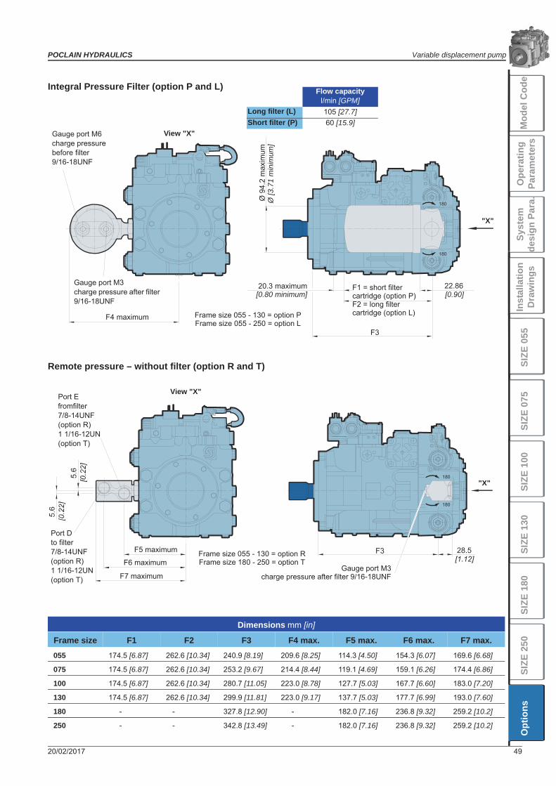
Integral Pressure Filter (option P and L)
Remote pressure – without filter (option R and T)
Dimensions mm [in]
Frame size F1 F2 F3 F4 max. F5 max. F6 max. F7 max.
055 174.5 [6.87] 262.6 [10.34] 240.9 [8.19] 209.6 [8.25] 114.3 [4.50] 154.3 [6.07] 169.6 [6.68]
075 174.5 [6.87] 262.6 [10.34] 253.2 [9.67] 214.4 [8.44] 119.1 [4.69] 159.1 [6.26] 174.4 [6.86]
100 174.5 [6.87] 262.6 [10.34] 280.7 [11.05] 223.0 [8.78] 127.7 [5.03] 167.7 [6.60] 183.0 [7.20]
130 174.5 [6.87] 262.6 [10.34] 299.9 [11.81] 223.0 [9.17] 137.7 [5.03] 177.7 [6.99] 193.0 [7.60]
180 - - 327.8 [12.90] - 182.0 [7.16] 236.8 [9.32] 259.2 [10.2]
250 - - 342.8 [13.49] - 182.0 [7.16] 236.8 [9.32] 259.2 [10.2]
Gauge port M6 charge pressure before filter 9/16-18UNF
Gauge port M3 charge pressure after filter 9/16-18UNF
F4 maximum
View "X"
"X"
20.3 maximum[0.80 minimum]
F1 = short filter cartridge (option P)F2 = long filter cartridge (option L)Frame size 055 - 130 = option P
Frame size 055 - 250 = option L
Ø 9
4.2
max
imum
Ø [3
.71
min
imum
]
Port Efromfilter7/8-14UNF(option R)1 1/16-12UN(option T)
F5 maximum
F6 maximum
F7 maximum
View "X"
Gauge port M3charge pressure after filter 9/16-18UNF
Frame size 055 - 130 = option RFrame size 180 - 250 = option T
"X"
Port Dto filter7/8-14UNF(option R)1 1/16-12UN(option T)
Flow capacityl/min [GPM]
Long filter (L) 105 [27.7]Short filter (P) 60 [15.9]

Variable displacement pump POCLAIN HYDRAULICS
50 20/02/2017

POCLAIN HYDRAULICS Variable displacement pump
20/02/2017 51
Syst
emde
sign
Par
a.M
odel
Cod
eO
pera
ting
Para
met
ers
Inst
alla
tion
Dra
win
gsSI
ZE 0
55SI
ZE 2
50O
ptio
nsSI
ZE 0
75SI
ZE 1
00SI
ZE 1
30SI
ZE 1
80

www.poclain-hydraulics.com
A18260X
A18586C
20/02/2017
Poclain Hydraulics reserves the right to make any modifications it deems necessary to the products described in this document without prior notification.The information contained in this document must be confirmed by Poclain Hydraulics before any order is submitted.Illustrations are not binding.The Poclain Hydraulics brand is the property of Poclain Hydraulics S.A.


![WEGEVENTILE - Poclain Hydraulics...Wegeventile - Hydraulik-Bauteile POCLAIN HYDRAULICS Technische Daten Nenngröße 610 Volumenstrom L/min [GPM] 60 [15,8] 100 [26,4] Betriebsdruck](https://static.fdocuments.net/doc/165x107/6122ff72c5b8534c137c4046/wegeventile-poclain-hydraulics-wegeventile-hydraulik-bauteile-poclain-hydraulics.jpg)