V.741 Enhancements - CSPFea. Doubly reinforced beam design. midas Gen V.741 Enhancements Analysis &...
39
Analysis & Design Part Concrete / Steel pushover analysis & safety verification as per Eurocode 8-3: 2004 Masonry pushover analysis & global assessment as per OPCM3431 Lateral-Torsional Buckling Analysis Improvement on Italian UNI code concrete material DB and much more… Pre/Post-processing part Addition of Linear Constraints function Automatically finding the major axis for response spectrum analysis Improvement on importing dxf file Addition of CEB-FIP 78 model code Web-based online manual including context-sensitive help and much more… V.741 Enhancements
-
Upload
truongnguyet -
Category
Documents
-
view
228 -
download
0
Transcript of V.741 Enhancements - CSPFea. Doubly reinforced beam design. midas Gen V.741 Enhancements Analysis &...
Analysis & Design Part
Concrete / Steel pushover analysis & safety verification as per
Eurocode 8-3: 2004
Masonry pushover analysis & global assessment as per OPCM3431
Lateral-Torsional Buckling Analysis
Improvement on Italian UNI code concrete material DB
and much more…
Pre/Post-processing part
Addition of Linear Constraints function
Automatically finding the major axis for response spectrum analysis
Improvement on importing dxf file
Addition of CEB-FIP 78 model code
Web-based online manual including context-sensitive help
and much more…
V.741 Enhancements

midas Gen V.741 Enhancements
Analysis & Design Part
1. Pushover analysis improvement
2. Important notice to existing users regarding pushover analysis
3. Concrete/Steel pushover analysis & safety verification as per Eurocode 8-
3:2004
4. Masonry pushover analysis & global assessment as per OPCM3431
5. Concrete design as per Eurocode 2:2004
6. Steel design as per Eurocode 3:2005
7. Improvement on Italian UNI code concrete material DB
8. Lateral-Torsional Buckling Analysis
9. Limit Strength for Tension only/Compression only Truss
10.Nonlinear Point Springs
11.Tens./Comp.-only, Hook & Gap elements in Material nonlinear analysis
12.Concrete design as per ACI318-05
13. Doubly reinforced beam design

midas Gen V.741 Enhancements
Analysis & Design
Pushover Global Control
Pushover Load cases
Define Pushover Hinge
Properties
Assign Hinge Properties
Perform Pushover Analysis
Pushover Results
Define Initial load, convergence criteria, stiffn
ess reduction ratio, etc.
Define incremental step, load pattern,
incremental method (load
control/displacement control), auto-
termination condition, etc.
Define whether to consider initial load and P-
Delta effect
Incremental Control Function : set a user-de
fined incremental function (for Load Control)
Specify element type and material type
Hinge properties by force components (Fx, Fy
Fz, Mx, My, Mz): yield strength, skeleton
curve type, P-M interaction, etc.
Assign hinge properties to elements
Yield strength is automatically calculated for
each element.
Pushover analysis results: Pushover curve,
Hinge Status Results, etc.
Various pushover graphs
Various pushover hinge result tables
1. Pushover analysis improvement
(1) Pushover Analysis Procedure
• Pushover analysis is fully revised and updated from pre-/post-processing to solver.
Upgrade Contents

midas Gen V.741 Enhancements
Analysis & Design
(2) Enhanced Usability
Pushover Global Control: defined in a single dialog
Pushover Hinge Properties
Pushover graph
Pushover Hinge result table
Force-Deformation graph, displacement graph by
steps, etc.
Hinge status, Plastic deformation, etc.
Initial load
Default value of stiffness reduction ratio (bi-linear/tri-
linear hinge curve)
Nonlinear Analysis Option (Maximum Iteration,
Convergence Criteria)
Scale Factor for Ultimate Rotation and Secondary
Seismic Elements as per Eurocode 8-3
User-oriented interface
Define hinge properties by elements (six components
can be defined in a single dialog.)
Hinge properties about y-axis and z-axis are
separately defined.
Show yield strength in real value as well as the ratio
of the yield surface.
Assign hinge properties by Drag & Drop
Check hinge properties using Pushover Hinge
Properties table
1. Pushover analysis improvement
midas Gen V.741 Enhancements
Analysis & Design
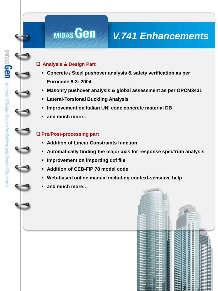
(3) Improved analysis process for Nonlinear Element and Hinge Properties
Nonlinear Element
Moment-Rotation (M-) type hinge can be used in Load control pushover analysis.
Out-of-plane nonlinearity for wall elements of the plate type is reflected.
Distributed hinge is added. (Moment-curvature relation): Plasticity of the entire element considered.
Enter integration points (1~20) (* Only plasticity at both ends was considered for the present Multi-linear
type element)
Defining hinge properties for nonlinear general link completely revised.
Moment-Rotation (M-) type hinge and Moment-Curvature (M-) type hinge can be used in combination.
Pushover Hinge Properties
PMM TYPE (Change in axial forces considered)
-RC Tri-linear: Crack surface (1st yield surface) can be defined.
-Steel Tri-linear: 1st and 2nd yield surfaces can be separately defined.
-Maximum yield moment about ± My, ± Mz can be individually defined.
Skeleton curve considering slip is newly added for truss element and general link.
The user can directly define the initial stiffness of nonlinear hinges.
The user can directly define yield deformations.
1. Pushover analysis improvement

midas Gen V.741 Enhancements
Analysis & Design
(4) Improved Analysis Control & Speed
Simple Analysis Control
Improvement on load control method: 100% of applied load is accurately reflected in analysis.
Addition of Load Incremental Method
- Auto-stepping control: The first step is loaded up to 90% of the elastic limit of the structure. Further steps a
re automatically divided into the ratio of .
‐ Equal step (1/nstep): Equally divided steps.
- User defined Increment-control function
Auto-terminating condition is added.
- Current Stiffness Ratio: If the analysis results do not converge, analysis will be terminated.
- Auto-terminating condition by story drift ratio is added (Displacement Control).
Analysis Speed
Analysis speed is improved by adopting INCORE Solver. Analysis time is reduced to 40-50% compared
to the old version.
[Comparing analysis time]
old
versionVer.7.4.1
Ver.7.4.1 / old ver
sion
Skyline Solver47.570
[sec]
20.790
[sec]43.70 [%]
Mult-Frontal So
lver
46.780 [se
c]
20.490 [se
c]43.80 [%]
Number of Nodes: 135
Number of elements:beam (234), wall (12)
Nonlinear hinges are assigned to all the elements.
Incremental method: Displacement Control (50 steps)
1
1
( 1) /n
i
n i i
1. Pushover analysis improvement

midas Gen V.741 Enhancements
Analysis & Design1. Pushover analysis improvement
Design > Pushover Analysis > Perform Pushover Analysis
Results > Forces > Beam Diagrams
Old Version
New Version (Ver.7.4.1)
Linear Interpolation of the member
forces at each end was used for
forces at intermediate points.
Inaccurate member forces at intermediate points if
distributed loads were present unless separate
calculations were made.
Linear interpolation
Display member forces at every quarter point (i, 1/4, 2/4, 3/4, j)True member forces are
displayed reflecting distributed
loads.
Calculating member
forces at 5 points
(5) Improvement on displaying member forces due to pushover analysis
* For detailed information, refer to Pushover user’s guide at http://eng.midasuser.com.

midas Gen V.741 Enhancements
Analysis & Design
(1) Data conversion – Analysis control data
2. Important Notice to Existing Users
Old Version
1
Convergence Criteria → Moved to the Pushover Global Control dialog.
Initial Load → Moved to the Pushover Global Control dialog.
1
2
2
New Version(Ver.7.4.1)

midas Gen V.741 Enhancements
Analysis & Design
(2) Data conversion – Pushover Load Case
Number of Incremental Steps → Moved to the Pushover Load Case dialog.
(Number of Increment Steps can be set by load cases separately.)
Auto-stepping Control → Control method is totally revised.
1
2
Old Version New Version(Ver.7.4.1)
1
2
2. Important Notice to Existing Users

midas Gen V.741 Enhancements
Analysis & Design
(3) Data conversion – Hinge properties type
Old Version
– Define hinge properties by components
New Version (Ver.7.4.1)
– Define hinge properties by elements
Old Version Multi-linear → New Version
Moment-Curvature (Lumped)
Old Version FEMA
→ New Version Moment-Rotation
1
2
2. Important notice to existing users
1
2

midas Gen V.741 Enhancements
Analysis & Design
(4) Data conversion – Hinge properties assignment
Nonlinear hinge properties were defined by force components in the old version, however in the new version,
they are defined by elements. For example, in order to assign axial and flexural hinge properties to one
element in the old version, the user defined two different hinge properties. However, in the new version, only
one hinge property defining the axial and flexural properties is needed.
In the new version, when the user opens a model file created in the old version, the component hinge
properties will be individually assigned to the corresponding elements (one component hinge property per
element). So, the converted file size of the model may become larger than that of the old version. This is not
the general way to define hinge properties in the new version, but it is intended to avoid errors in converting
files. Refer to Assign Hinge Properties to learn how to assign hinge properties in the new version.
Old Version New Version(Ver.7.4.1)
Hinge properties defined by components
* 3 components of hinge properties have been defined.
1
2
1
2
Hinge properties by component are assigned to the elements.
* 36 component hinge properties have been assigned to the elements.
1
2
Hinge properties defined by elements 1
* 9 hinge properties by elements have been defined.
Hinge properties by elements are assigned to the elements.
* Hinge properties have been assigned to 9 elements.
1
2
2. Important Notice to Existing Users

midas Gen V.741 Enhancements
Analysis & Design
(1) Pushover Hinge Properties
Design > Pushover Analysis > Pushover Global Control
Design > Pushover Analysis > Pushover Load Cases
Design > Pushover Analysis > Define Pushover Hinge Properties
Design > Pushover Analysis > Assign Pushover Hinge Properties
a. Pushover hinge type as per Eurocode 8:2004 is newly added.
b. 6 components (Fx, Fy, Fz, Mx, My & Mz) can be defined in Pushover Hinge Properties dialog box.
c. When PMM hinge is defined, yield moments considering P-M interaction can be checked by
clicking on [Show Ratio] button.
d. Deformation capacity is calculated based on Eurocode 8-3:2004, and the user can check the
calculated values in a detailed report.
Upgrade Contents
3. Concrete/Steel Pushover analysis as per Eurocode8:2004

midas Gen V.741 Enhancements
Analysis & Design
Story Shear vs Story Drift
(2) Pushover analysis results & Target displacement
Design > Pushover Analysis > Pushover Hinge Status Results
Design > Pushover Analysis > Pushover Curve
Design > Pushover Analysis > Pushover Story Graph > Story Shear Graph
a. Target displacements (demands & steps corresponding to the limit states of DL, SD & NC ) for the
design spectrum are displayed in the Pushover Curve dialog box.
b. Hinge status (Ductility, Deformation, Force, Status of yielding) for each pushover step resulting
from the Pushover analysis is displayed in Contours.
Upgrade Contents
3. Concrete/Steel Pushover analysis as per Eurocode 8:2004
DL SD NC
midas Gen V.741 Enhancements
Analysis & Design
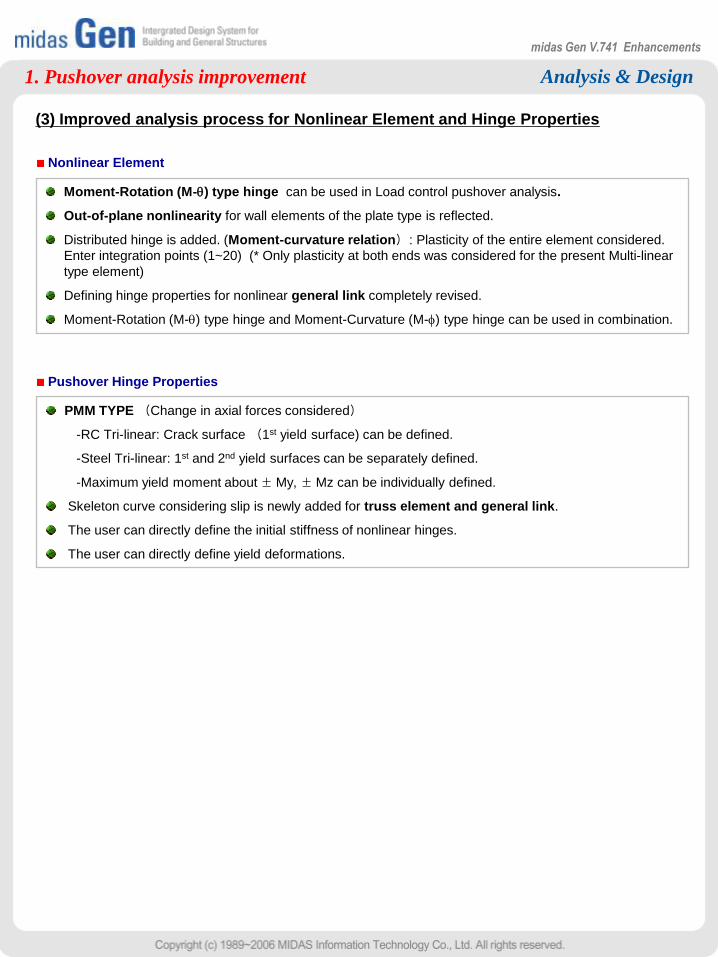
(3) Safety Verification
Design > Pushover Analysis > Safety Verification Table
In the safety verification table, the capacity of both
ductile and brittle components are compared to the
demand.
Upgrade Contents
3. Concrete/Steel Pushover analysis as per Eurocode 8:2004
* For detailed information, refer to „Pushover Analysis as per Eurocode8:2004’ tutorial at http://eng.midasuser.com.

midas Gen V.741 Enhancements
Analysis & Design4. Masonry Pushover analysis as per OPCM3431
(1)Pushover hinge properties of a masonry structure
Design > Pushover Analysis > Define Pushover Hinge Properties
Pushover analysis for masonry structures is newly implemented.
Different hinge properties for new buildings and existing buildings are provided.
Different hinge properties for masonry piers and masonry spandrels are provided.
Upgrade Contents

midas Gen V.741 Enhancements
Analysis & Design
(2) Pushover analysis results & Global assessment
Design > Pushover Analysis > Pushover Hinge Status Results
Design > Pushover Analysis > Pushover Curve
Assessment results for limit states of DL & SD between the capacity and the demand are
displayed in terms of global response in Pushover Curve.
Hinge status (Ductility, Deformation, Force, Status of yielding) for each pushover step resulting
from the Pushover analysis is displayed in Contours.
Upgrade Contents
4. Masonry Pushover analysis as per OPCM3431
midas Gen V.741 Enhancements
Analysis & Design
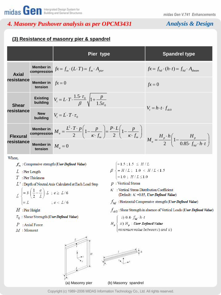
(3) Resistance of masonry pier & spandrel
4. Masonry Pushover analysis as per OPCM3431
Pier type Spandrel type
Axial
resistance
Member in
compression
Member in
tension
Shear
resistance
Existing
building
New
building
Flexural
resistance
Member in
compression
Member in
tension
( ) m m pierfx f L T f A
0fx
'
0tV L T
0
0
1.51
1.5t
pV L T
2
1 12 2
u
m m
L T p p P L pM
f f
0uM
( )hd hd sbeamfx f h t f A
0fx
0t vkV h t f
12 0.85
p p
u
hd
H h HM
f h t
(a) Masonry pier (b) Masonry spandrel

midas Gen V.741 Enhancements
Analysis & Design5. Concrete Design as per Eurocode 2:2004
(1) ULS & SLS Design
Design > Concrete Design Parameters > Design Code
Design > Concrete Design Parameters > Serviceability Parameters
Design > Concrete Design Parameters > Partial Safety Factors for Material Properties
RC design as per Eurocode 2:2004 is newly implemented.
Ultimate Limit States Design (Beam, Column, Wall) - New for Ver.7.4.1
Serviceability Limit States Design (Stress limit, Crack width, Deflection)
Upgrade Contents

midas Gen V.741 Enhancements
Analysis & Design
(2) Auto-Generation of Load Combination as per Eurocode 2:2004
Results > Combinations
Auto generation of load combinations based on Eurocode 2:2004 is newly implemented.
Orthogonal Effect of Earthquake load can be considered.
Upgrade Contents
5. Concrete Design as per Eurocode 2:2004

midas Gen V.741 Enhancements
Analysis & Design
Design > Concrete Code Design > Beam Design
Design > Concrete Code Design > Column Design
Design > Concrete Code Design > Wall Design
(3) Design Report
Design results are displayed in both graphical and detailed report format.
Upgrade Contents
5. Concrete Design as per Eurocode 2:2004
* For detailed information, refer to „Concrete Design as per Eurocode2:2004’ tutorial at http://eng.midasuser.com.

midas Gen V.741 Enhancements
Analysis & Design6. Steel Design as per Eurocode 3:2005
(1) ULS & SLS Design
Design > Steel Design Parameters > Design Code
Design > Steel Design Parameters > Serviceability Parameters
Design > Steel Design Parameters > Partial Safety Factors
Steel design as per Eurocode 3:2005 is newly implemented.
Ultimate Limit State Design (Beam, Column, Brace) - New for Ver.7.4.1
Serviceability Limit States Design (Deflection)
Upgrade Contents

midas Gen V.741 Enhancements
Analysis & Design
Resistance Check
Deflection Check
Design > Concrete Code Design > Beam Design
Design > Concrete Code Design > Column Design
Design > Concrete Code Design > Wall Design
(2) Design Report
Design results are displayed in both graphical and detailed report formats.
Upgrade Contents
6. Steel Design as per Eurocode 3:2005

midas Gen V.741 Enhancements
Analysis & Design
Specification
Material DBConcrete Material DB Eurocode 2:2004
Steel Material DB Eurocode 3:2005
Section DB Steel Section DB UNI, BS, DIN
Load
Static Wind load Eurocode 1:2005
Static Seismic Load Eurocode 8:2004
Response Spectrum Function Eurocode 8:2004
Pushover Analysis
Masonry Pushover OPCM3431
RC Pushover Eurocode 8:2004
Steel Pushover Eurocode 8:2004
Design
Load Combination Eurocode 0:2002
ULS Concrete Frame Design Eurocode 2:2004
ULS Steel Frame Design Eurocode 3:2005
SLS Concrete Frame Design Eurocode 2:2004
SLS Steel Frame Design Eurocode 3:2005
Eurocode implementation status in midas Gen
Related Codes
Eurocode 0:2002
Eurocode 2:2004
Eurocode 3:2005
Eurocode 8:2004
OPCM3431
UNI
BS
DIN

midas Gen V.741 Enhancements
Analysis & Design
UNI code
concrete DB
Design Strength (MPa) Modulus of Elasticity (MPa)
old version ver.7.4.1 old version ver.7.4.1
Rck 10 - 8 - 2.5331E+4
Rck 15 - 12 - 2.7085E+4
Rck 20 - 16 - 2.8607E+4
Rck 25 25 20 2.8500E+4 2.9961E+4
Rck 30 30 25 3.1220E+4 3.1475E+4
Rck 35 35 28 3.3721E+4 3.2308E+4
Rck 40 40 32 3.6049E+4 3.3345E+4
Rck 45 45 35 3.8236E+4 3.4077E+4
Rck 50 50 40 4.0305E+4 3.5220E+4
• In the concrete material DB as per Italian UNI code, Rck10, Rck15 & Rck20 have been added.
• In the old version, cubic strength was used for design strength in Eurocode design. In ver.7.4.1, it is
corrected to cylindrical strength.
•When the user opens a model file which is created in the old version, design strength will not be updated.
However when the user opens the „Material Data‟ dialog or „Modify Concrete Materials‟ dialog and
changes the material properties of UNI code, the design strength of all the UNI code assigned elements
in the model file will be updated correct design strength.
Effects & Usage
7. Improvement on Italian UNI code concrete material DB
Upgrade Contents

midas Gen V.741 Enhancements
Analysis & Design
• Addition of lateral-torsional buckling consideration
in analysis.
Test Model
Buckling Result Comparison
x
y
zA
Flexual-torsional buckle
A-A’
A’Force
Lateral-torsional Buckling
Force
Mode No Lateral Torsion Lateral Torsion Inc.
1 56.49929 33.26758
2 57.61738 57.6344
3 69.3207 58.63127
4 70.54121 70.61125
5 119.1424 71.42605
6 119.7788 71.79503
7 145.7739 72.97477
8 146.4525 100.135
9 216.0261 106.5486
10 228.6329 119.2809
Model > Buckling Analysis Control
8. Lateral-Torsional Buckling Analysis
• The buckling mode around the weak axis is
considered for a member which has to resist both
bending and shear. This results in more accurate
critical load factors.
Effects & Usage
Upgrade Contents

midas Gen V.741 Enhancements
Analysis & Design
•An additional method of representing material nonlinearity. Both Tension only / Compression only limits
are provided.
• Addition of Limit Strength for Tension only/Compression only Trusses.
Model > Elements > Create Elements
Tensile
Force Limit
u
P
Compressive
Force Limit
u
P
9. Limit Strength for Tension only/Compression only Truss
Effects & Usage
Upgrade Contents

midas Gen V.741 Enhancements
Analysis & Design
• Linear, Multi-Linear and Compression-only springs can be used for modeling the soil structure
interaction e.g. integral bridge.
• By using Multi-Linear (Bi-Linear) springs, the effects of temperature, braking and acceleration in rail
structure interaction can be determined.
10. Nonlinear Point Springs
• Compression-only/Tension-only and Multi-Linear Type point springs have been added.
Multi-Linear Point Spring SupportPoint Spring SupportCompression-only/Tension-only
Point Spring Support
Model > Boundary > Point Spring Support
Effects & Usage
Upgrade Contents

midas Gen V.741 Enhancements
Analysis & Design11. Tens./Comp.-only, Hook & Gap element in Material nonlinear analysis
Elements, which can be used in material nonlinear analysis and/or geometry nonlinear analysis
• In the old version, Tension-only, Compression-only, Hook and Gap elements were changed to truss
elements in nonlinear analysis. In ver.7.4.1, those elements can be now used in material nonlinear
analysis reflecting their true nonlinear properties.
Upgrade Contents
Element Material Nonlinear
Truss yes
Tension only yes
Hook yes
Cable yes†
Compression only yes
Gap yes
Beam yes†
Plate – Thick yes
Plate – Thin Yes*
Plane Stress yes
Plane Strain yes
Axisymmetry yes
Solid yes
† : Corresponding elements are considered as linear elements in analysis.
* : Corresponding thin plate elements are considered as thick plate elements.

midas Gen V.741 Enhancements
Analysis & Design12. Concrete Code Design as per ACI 318-05
Design > Concrete Design Parameters > Design Code
Related Codes
ACI318-05, TWN-USD 92
Check on in order to design doubly reinforced beams.
Maximum tensile rebar limit can be specified by entering the
ratio(k) as a factor of the reinforcement limit (0.75ρb).
Upgrade Contents
13. Doubly Reinforced Beam Design
Design > Concrete Design Parameters
> Design Criteria for Rebar, Design Criteria for Rebar by member
Design > Concrete Design Parameters > Design Criteria for Rebar by member

midas Gen V.741 Enhancements
Analysis & Design
Design > Concrete Design Parameter > Design Criteria for Rebars
Design > Concrete Code Design > Beam Design / Column Design
The program did not provide required rebar areas for the column design, which sometimes caused
inconvenience when the user tried to manipulate reinforcement.
For this, minimum rebar spacing limit can be ignored in Gen V741. Older versions always applied
the spacing requirement in the design code. Checking off “Consider Spacing Limit for Main Rebar”
allows the user to find the required rebar area beyond the code required spacing.
Upgrade Contents
TWN-USD 92 Clause 15.4.4.2 indicates that “transverse reinforcement shall be proportioned to resist
shear assuming Vc=0 when both of the following conditions occur…..” In Gen V741, even though
such conditions occur, the user can include a part of shear strength of concrete as well as shear
reinforcement. This function is intended to reflect the engineering practice in Taiwan.
Upgrade Contents
15. Scale factor for shear strength of concrete
Design > Concrete Design Parameter > Design Code
Design > Concrete Code Design > Beam Design
14. Control of minimum rebar spacing for beam/column design

midas Gen V.741 Enhancements
Pre/Post-processing part
1. Addition of Linear Constraints function
2. Automatically finding the major axis for response spectrum analysis
3. Improvements on speed of calculation of Masses
4. Improvements on speed of calculation of Floor Load
5. Plate offset
6. Improvement on importing dxf file
7. Display general link element deformations of Time History Analysis result
8. Addition of CEB-FIP 78 model code
9. Section shape display for irregular section imported from SPC
10. Displaying wall member forces by Wall ID
11. Automatic file recovery
12. Web-based online manual including context-sensitive help
13. Default unit system is changed from kips-ft to kN-m.

midas Gen V.741 Enhancements
Pre/Post-processing
•Rigid Link can be applied in terms of global axis only. Using Linear Constraints, it enables to constrain
displacement/rotation between nodes in terms of any axis as well as global axis.
Model > Boundaries > Linear Constraints
•A Linear Constraints function is newly implemented to constrain a specific node to subordinate to the
movements of certain nodes.
Explicit Type
1. Addition of Linear Constraints function
Effects & Usage
Upgrade Contents
The figure above shows an application example in which a
connection is made between a 3-D structure consisted of solid
elements and a thin plate consisted of plate elements. Since
solid elements do not have stiffness against rotational DOF,
they cannot restrain the rotational behavior of the connected
plate. If the rotational DOF of the connected part is restrained
using Eq. (1) below, the plate elements would generally behave
perpendicularly to the connection
Eq. (1) ,3 ,1 ,2
1 1Y X XR U U
h h

midas Gen V.741 Enhancements
Pre/Post-processing
Loads > Response Spectrum Analysis Data > Response Spectrum Load Cases
Excitation angle of response spectrum is automatically
taken as the major-axis direction of a building.
Upgrade Contents
2. Automatically finding the major axis of a building
Major axis
55 60 65 70 75 80 85 90 95 100 105 110
650
700
750
800
850
Ba
se
Sh
ea
r F
orc
e(t
on
f)
Exitation Angle(degree)
Maximum Base Shear Force
(angle=79, Base Shear Force=858.39)
Accidental eccentricity is automatically up
dated based on the major axis.

midas Gen V.741 Enhancements
Pre/Post-processing3. Improvements on calculation of Masses
Model > Masses > Load to Masses
Related Functions
Load > Load Tables > Nodal Body Forces table
Model > Masses > Floor Diaphragm Masses
Model > Masses > Nodal Masses Table
Results > Result Tables > Story > Weight Irregularity Check Table
The maximum number of load cases which are available in Load to
Masses function has been increased to „50‟ in order to convert
various load cases into masses .
Increase in speed of calculating mass data.
Upgrade Contents
4. Improvements on calculation of Floor Load Data
Load > Define Floor Load Type
Load > Assign Floor Load Type
Model information Status Ver.7.2.1 Ver.7.4.1 Improvement
- Elements: 31859
- Story: 30
- Floor loads are
assigned to all the floors.
When calculating
floor loads before
performing analysis
160 sec. 66 sec. 2.4 times
* Computer information: Intel(R) Pentium(R) 4 CPU 2.80GHz, 1GB RAM
Increase in speed of calculating Floor Load data
Upgrade Contents
Example
* Test model

midas Gen V.741 Enhancements
Pre/Post-processing
In the Tree Menu
File > Import > AutoCAD DXF File
Model > Properties > Thickness
Plate offset is newly added.
Offset is applicable in the element‟s local-z direction.
Upgrade Contents
Various polyline types such as polygon, triangle, rectangle, etc. can be imported to midas Gen as
plate elements in a DXF format.
Upgrade Contents
6. Improvement on importing dxf file
5. Plate Offset
Triangle polyline in AutoCAD Plate elements in midas Gen

midas Gen V.741 Enhancements
Pre/Post-processing7. Display general link element deformations of Time History Analysis result
Model > Results > Result Tables > Time History Analysis > General Link
• General link element deformations of time history analysis results are tabulated in a Spread Sheet
format.
Time History Analysis (General Link) Table
•CEB-FIP (1978) model code as well as CEB-FIP (1990) model code can be applied in the construction
stage analysis.
Model > Properties > Time Dependent Material (Creep/Shrinkage)
Time Dependent Material (Creep/Shrinkage) Dialog CEB-FIP Code (1978) Result View
8. Addition of CEB-FIP 78 model code
Upgrade Contents
Upgrade Contents

midas Gen V.741 Enhancements
Pre/Post-processing9. Section shape display for irregular section imported from SPC
View > Display
•Section Shape Display function for irregular section
imported from SPC is newly implemented.
Frame view with Section Shape display option
Hidden Surface view
Upgrade Contents

midas Gen V.741 Enhancements
Pre/Post-processing
Results > Forces > Wall Forces/Moments
Results > Forces > Wall Diagrams
Wall member forces are displayed by Wall IDs rather than by wall elements for clarity.
Upgrade Contents
If midas Gen program encounters a problem and terminates itself in an abnormal way, the working file
may be recovered in most times. The saved file name is file name_restore.mgb.
Upgrade Contents
11. Automatic file recovery
10. Displaying wall member forces by Wall ID
Previous version:
Wall forces by Wall Elements
V741:
Wall forces by Wall IDs

midas Gen V.741 Enhancements
Pre/Post-processing12. Web-based online manual including context-sensitive help
•A web-based online manual is available. Pressing [F1] Key will open the web-based online manual
provided that you are connected to the internet.
• Pressing the [F1] key gives the user context-sensitive help for all dialogs.
• Default unit system can be changed in the Tools>Unit System menu.
13. Default unit system is changed from kips-ft to kN-m.
Upgrade Contents
Upgrade Contents