University of Southern Queensland · University of Southern Queensland Faculty of Engineering and...
94
Transcript of University of Southern Queensland · University of Southern Queensland Faculty of Engineering and...


University of Southern Queensland
Faculty of Engineering and Surveying
The Development of a New Multi-Directional Fall arrest Device
A dissertation submitted by
Alan Grant Lance SILVA
In fulfillment of the requirements of
Courses ENG4111 and ENG4112 Research Project
towards the degree of
Bachelor of Engineering (Mechanical Engineering)
Submitted: 25th October, 2004

i
University of Southern Queensland
Faculty of Engineering and Surveying
Abstract
This research project has been undertaken to develop a mechanical solution that will automaticallyarrest the fall of a person working at height in any attitude while allowing unrestricted movement innormal use and to simplify the device set up.
Current fall arrest equipment used in industry are of a cumbersome design with limited application thatcan lead to potentially serious injury to the user.
Following a review of fall arrest systems used in industrial and recreational applications, amethodology for the design, prototype construction and testing procedures was
established.
This dissertation documents the process used to produce a working back up fall arrest device in thefollowing areas:
- Conceptual design. - Construction of a prototype. - Testing of the prototype. - Evaluation of the design and testing.

University of Southern Queensland
Faculty of Engineering and Surveying
The Council of thSurveying, and thResponsibility forAssociated with th
Persons using all of the Council of Surveying or the s
This dissertation rthis exercise. Thecontribute to the odocument, the assassociated appendentirely at the risk
Prof G BakerDeanFaculty of Engine
ENG411 & ENG4112 Research Project
Limitations of Use
e University of Southern Queensland, its Faculty of Engineering ande staff of the University of Southern Queensland, do not accept any the truth, accuracy or completeness of material contained within oris dissertation.
or any part of this material do so at their own risk, and not at the riskthe University of Southern Queensland, its Faculty of Engineering andtaff of the University of Southern Queensland.
eports an educational exercise and has no purpose or validity beyond sole purpose of the course pair entitled ‘Research Project’ is toverall education within the student’s chosen degree program. Thisociated hardware, software, drawings and other material set out in theices should not be used for any other purpose: if they are used so, it is of the user.
ering and Surveying

Certification
I certify that the ideas, designs and experimental work, results, analyses and Conclusions set out in this dissertation are entirely my own effort, except where Otherwise indicated and acknowledged.
I further certify that the work is original and has not been previously submitted for assessment in any other course or institution, except where specifically stated.
Alan Grant Lance SILVA
Student Number: 0039812125
________________________________________ Signature
17th October 2004 ________________________________________ Date

ii
Acknowledgements
I would like to acknowledge the generous assistance, guidance and support given to me whilstundertaking the research project without which many of the tasks would have been difficult toachieve in the limited time I have had to complete the project.
Firstly to the research project supervisor,
Dr Selvan Pather
Of the University of Southern Queensland Engineering and Surveying Faculty,for his valued guidance and suggestions throughout the whole period taken to complete theproject.
Secondly,
Mr Boris Rogelja
Of Single Rope Technique Equipment, Padstow, New South Wales, for the generous use of histime, suggestions and use of his testing equipment to conduct the static testing on the prototypedevice.
Lastly,
My wife Christine and daughters, Tia Rana and Natasja Raine
For their patience and support during my two month absence while constructing and testing thedevice in Sydney, and the time taken to produce the project dissertation.

Table of Contents• Abstract Page i
• Acknowledgements Page ii
• List of Drawings Page iii
• List of Figures Page iv
• List of Tables Page vii
• Glossary Page viii
• Chapter 1. Introduction Page 11.1. Introduction.1.2. The Need for Research.1.3. Dissertation Overview.1.4. Project Objectives.1.5. Chapter Conclusion.
• Chapter 2. Background Literature Review of Fall Arrest Methods Page 32.1. Introduction.2.2. Government Legislation for Workplace and Recreation Fall Prevention.2.3. Workplace fall related accident statistics.2.4. Recreation Fall Related Accident Statistics.2.5. Australia/New Zealand Standards for Workplace Fall Arrest Methods.2.6. International Standards for Recreational Fall Arrest Methods.2.7. Fall Prevention Measures Used in the Workplace.2.8. Fall Prevention Methods Used in Recreational Areas.2.9. Chapter Conclusion.
• Chapter 3. Current Type 1 Fall Arrest Fall Arrest Device Evaluation Page 233.1. Introduction.3.2. Current Fall Arrest Models Selected for A Critical Evaluation.3.3. Issues Identified From the Critique Evaluation.3.4. Chapter Conclusion.
• Chapter 4. Design Criteria for the Research Project Back Up Fall Arrest Device Page 244.1. Introduction.4.2. Design Considerations.4.3. Chapter Conclusion.
• Chapter 5. Prototype Design and Manufacture Page 415.1. Introduction.5.2. Material Selection.5.3. Hand Stress Analysis Calculations for Key Prototype Components.5.4. SOLIDworks Prototype Modeling of a Fall Arrest Prototype.5.5. Finite Element Stress Analysis of Prototype Design Components.5.6. Manufacturing the Prototype Components.5.7. Chapter Conclusion.

• Chapter 6. Testing and Result Analysis for the Back Up Fall Arrest Prototype Page 526.1. Introduction.6.2. Types of Verification Testing Processes for the Back Up Rope Grab Fall Arrest Device.6.3. Results of Testing.6.4. Analysis of the Testing Completed to Date and Feedback for the Design Process.6.5. Chapter Conclusion.
• Chapter 7. Conclusion Page 597.1. Introduction.7.2. The Research Project Objectives.7.3. Achieving the Objectives.7.4. Deficient Areas of the Back Up Fall Arrest Device.7.5. Further Work for the Back Up Fall Arrest Device Concept
• List of References Page R.1
• AppendicesAppendix A: Project Specification Page A.1
Appendix B: Current Fall arrest Devices - An Evaluation Critique Page B.1
Appendix C: Singapore Police Report Page C.1
Appendix D: Fall Hazards, Risk Assessment and Practical Methods for Page D.1 Eliminating/ Prevention – An Overview
D.1. Fall Hazard Risk Assessment.
Appendix E: ‘Back of the Envelope’ Stress Calculations For the Page E.1 Prototype Design
E.1. Analysis Information.E.2. Forces On Blocking Cam and Guide Pulley Shafts.E.3. Minimum Cam Shaft Size.E.4. Minimum Guide Pullet Shaft Size.E.5. Forces on Trigger Link ShaftsE.6. Forces On Clutch Pulley ShaftE.7. Overall Shaft Design FactorE.8. Bearing Stress/Loads at Clutch Frame and Hinge Frame Shaft HolesE.9. Trigger Link Stress Analysis
Appendix F: Finite Element Analysis of Back Up Fall Arrest Page F.1 Prototype Design
F.1. Initial Design Cam Shaft AnalysisF.2. Finial Design Cam Shaft AnalysisF.3. Trigger Link AnalysisF.4. Hinge Frame Analysis
Appendix G: Clutch and Trigger Concepts for Back-Up Fall Arrest Page G.1 Device Prototype Design
G.1. Mechanical Concept Analysis for a Back-Up Fall Arrest DeviceG.2. Fall Arrest Mechanics for a Centrifugal Brake MechanismG.3. Fall Arrest Mechanics for a Back Up Fall Arrest Prototype Design
Appendix H: SOLIDworks Component Models and Production Drawings Page H.1

iii
List of Drawings
Appendix H
Drawing: SOLIDworks Model Back Up Fall Arrest Device Assembly Page H4Drawing: SOLIDworks Model Back Up Fall Arrest Device Cam Left Hand Page H6Drawing: SOLIDworks Model Back Up Fall Arrest Device Cam Right Hand Page H8Drawing: SOLIDworks Model Back Up Fall Arrest Device Cam Shaft Page H10Drawing: SOLIDworks Model Back Up Fall Arrest Device Centering Pin Page H12Drawing: SOLIDworks Model Back Up Fall Arrest Device Clutch Spring Page H14Drawing: SOLIDworks Model Back Up Fall Arrest Device Clutch Frame Page H16Drawing: SOLIDworks Model Back Up Fall Arrest Device Clutch Pulley Page H18Drawing: SOLIDworks Model Back Up Fall Arrest Device Clutch Pulley Bush Page H20Drawing: SOLIDworks Model Back Up Fall Arrest Device Clutch Roller Page H22Drawing: SOLIDworks Model Back Up Fall Arrest Device Clutch Shaft Page H24Drawing: SOLIDworks Model Back Up Fall Arrest Device Guide Pulley Page H26Drawing: SOLIDworks Model Back Up Fall Arrest Device Guide Pulley Bush Page H28Drawing: SOLIDworks Model Back Up Fall Arrest Device Guide Pulley Shaft Page H30Drawing: SOLIDworks Model Back Up Fall Arrest Device Hinge Frame Page H32Drawing: SOLIDworks Model Back Up Fall Arrest Device Handle Page H34Drawing: SOLIDworks Model Back Up Fall Arrest Device Handle Set Screw Page H36Drawing: SOLIDworks Model Back Up Fall Arrest Device Latch Pin Page H38Drawing: SOLIDworks Model Back Up Fall Arrest Device Clutch Actuating Ring Page H40Drawing: SOLIDworks Model Back Up Fall Arrest Device Trigger Set Screw Page H42Drawing: SOLIDworks Model Back Up Fall Arrest Device Trigger Catch Page H44Drawing: SOLIDworks Model Back Up Fall Arrest Device Trigger Link Page H46Drawing: SOLIDworks Model Back Up Fall Arrest Device Trigger Link Shaft Page H48

iv
List of Figures
Chapter 2.Figure 2.1. Fixed Working Platforms. Page 10Figure 2.2. Work Positioning System. Page 13Figure 2.3. (a). Industrial Rope Access Descent. Page 15 Figure 2.3. (b). Industrial Rope Access Ascent. Page 15Figure 2.4. Abseiling Descent. Page 16Figure 2.5. Bottom Belay Braking. Page 17 Figure 2.6. Frog Method of Ascender Rope Grab Attachment. Page 17Figure 2.7. Dynamic Rope Belay of a Caver Climbing a Caving Ladder. Page 18Figure 2.8. Rockclimbing Fall Arresting. Page 19Figure 2.9. (a). The Most Severe Fall. Page 19Figure 2.9. (b). Less Severe Fall. Page 19Figure 2.10. Top Rope Belay. Page 20Figure 2.11. Solo Back Roped Rock Climb. Page 21Figure 2.12. Method of Roping up for Glacier Travel. Page 21
Chapter 3.Figure 3.1. Gibbs Ascender Model “Type 2” Rope Grab. Page 23Figure 3.2. (a). Aligning the Components. Page 24 Figure 3.2. (b). Inserting the Quick Release Pin. Page 24Figure 3.3. The Protector “Cobra” Model AC202A Rope Grab. Page 25Figure 3.4. (a). Two Distinct Hand Actions Used to Unlock the “Cobra”. Page 26 Figure 3.4. (b). Frame is Hinged Open to Accept the Safety Rope. Page 26Figure 3.5. Petzl “Ascension” Right Handed Rope Grab. Page 27Figure 3.6. (a). Open Cam and Lock Stop on Frame Using Thumb Page 29Figure 3.6. (b). Place Rope in Frame. Page 29
Figure 3.6. (c). Release Stop to Secure Cam Against Rope. Page 29Figure 3.7. Wren Industries “Silent Partner”. Page 31Figure 3.8. (a). Connecting the Safety Rope. Page 31
Figure 3.8. (b). The Clove Hitch is Placed Around the Drum. Page 31
Chapter 4.Figure 4.1. Wren Industries Silent Partner. Page 37 Figure 4.2. Proposed Clutch Mechanism. Page 37Figure 4.3. Cardboard and Polystyrene Modeling of a Rotating Frame Idea. Page 39Figure 4.4. The SOLIDworks Virtual Model of the Initial Design Idea. Page 40
Chapter 5.Figure 5.1. SOLIDworks Final Prototype Assembly Model of the Back Up Fall Arrest Device. Page 42Figure 5.2. SOLIDworks Exploded view of the Back up Fall Arrest Device Assembly. Page 43Figure 5.3. Hinge Frame in Closed and Latched Position. Page 44Figure 5.4. The Back Up Fall Arrest Prototype Design. Page 47Figure 5.5. Initial Assembly of Back Up Fall Arrest Prototype Device. Page 48Figure 5.6. The Initial Blocking Cam Units Found to be too Small. Page 48Figure 5.7. The Initial Trigger Release Mechanism That Was Resized. Page 49Figure 5.8. Clutch Pulley and Actuating Ring. Page 49
Chapter 6.Figure 6.1. Static Test Set Up For Testing Back Up Rope Grab/ Ascender Devices. Page 53Figure 6.2. Test Set Up For Dynamic Testing of Back Up Rope Grabs. Page 54Figure 6.3. Test set-up for the Back Up Fall Arrest Clutch and Cam Release Mechanism. Page 55

v
Appendix EFigure E.1. Sketch of Back Up Fall Arrest Device In Orientated Fall Arrested Position Page E1Figure E.2. Sketch of Blocking Cam and Guide Pulley Loads Page E2Figure E.3. Sketch of Free Body Diagram for Blocking Cam and Guide Pulley Loads Page E2Figure E.4. (a) Sketch of Cam Shaft Loads Page E3Figure E.4 (b) Sketch of FBD for Cam Shaft Loads Page E3Figure E.5. (a) Sketch of Trigger Link Shaft Loads Page E4Figure E.5. (b) Sketch of FBD for Trigger Link Shaft Loads Page E4Figure E.6 Sketch of Clutch Shaft Loading Based on Rope Path Centre Line Page E5Figure E.7. Sketch of FBD for Clutch Shaft Loading Page E5Figure E.8. Sketch of Shaft Groove Nomenclature for Grooved Shaft Bending Page E6Figure E.9. Sketch of Shaft Cam Shaft Under Blocking Cam Distributed Load Page E7Figure E.10. (a) Shear Force Diagram for Blocking Cam Shaft Page E8Figure E.10. (b) Bending Moment Diagram for Blocking Cam Shaft Page E8Figure E.11. Bearing Stress for Clutch and Hinge Frames at Shaft Holes Page E9Figure E.12. Trigger Link Section Sketch Page E10Figure E.13. Trigger Link Section A-A Sketch Page E11Figure E.14. Trigger Link Section B-B Sketch Page E11Figure E.15. Vector Force Diagram at Section B-B Page E12
Appendix FFigure F.1 Constraints and Distributed Load Applied to Simplified Initial Cam Shaft ANSYS Page F1 Model Figure F.2 Initial Cam Shaft ANSYS Solution Page F2Figure F.3 Constraints and Distributed Load Applied to Simplified Final Cam Shaft ANSYS Page F3 Model Figure F.4 Final Cam Shaft ANSYS Solution Page F3Figure F.5 Constraints and Distributed Load Applied to Simplified Trigger Link ANSYS Model Page F4Figure F.6 Final Trigger Link ANSYS Solution Page F5Figure F.7 COSMOSxpress Trigger Link Plot showing the von Mises stress levels Page F6Figure F.8 Constraints and Distributed Load Applied to Simplified Hinge Frame ANSYS Page F7 Model Figure F.9 Final Hinge Frame ANSYS Solution Page F7Figure F.10 COSMOSxpress Hinge Frame Plot showing the von Mises stress levels Page F8
Appendix GFigure G.1 Clutch Mechanism Nomenclature Page G2Figure G.2 (a) FBD of Forces on Upper Roller Page G2Figure G.2 (b) FBD of Forces on Lower Roller Page G2Figure G.3 Final Design Layout of Clutch Mechanism Page G3Figure G.4 Vector Forces Generated by Rope Sliding Over the Locked Clutch Pulley Page G4Figure G.5 Fall Forces Generated by Unlocked Falling Fall Arrest Device and Locked Fall Page G4 Arrest Device
Appendix HFigure H.1 Drawing Construction of an Epicycloid Page H1 Figure H.2 Initial Layout Sketch of Back Up Fall Arrest Device Design Page H2Figure H.3 SOLIDworks Model Back Up Fall Arrest Device Prototype Assembly Page H3Figure H.4 SOLIDworks Model Back Up Fall Arrest Device Prototype Cam Left Hand Page H5Figure H.5 SOLIDworks Model Back Up Fall Arrest Device Prototype Cam Right Hand Page H7Figure H.6 SOLIDworks Model Back Up Fall Arrest Device Prototype Cam Shaft Page H9Figure H.7 SOLIDworks Model Back Up Fall Arrest Device Prototype Centering Pin Page H11Figure H.8 SOLIDworks Model Back Up Fall Arrest Device Prototype Clutch Spring Page H13Figure H.9 SOLIDworks Model Back Up Fall Arrest Device Prototype Clutch Frame Page H15Figure H.10 SOLIDworks Model Back Up Fall Arrest Device Prototype Clutch Pulley Page H17

vi
Figure H.11 SOLIDworks Model Back Up Fall Arrest Device Prototype Clutch Pulley Bush Page H19Figure H.12 SOLIDworks Model Back Up Fall Arrest Device Prototype Clutch Roller Page H21Figure H.13 SOLIDworks Model Back Up Fall Arrest Device Prototype Clutch Shaft Page H23Figure H.14 SOLIDworks Model Back Up Fall Arrest Device Prototype Guide Pulley Page H25Figure H.15 SOLIDworks Model Back Up Fall Arrest Device Prototype Guide Pulley Bush Page H27Figure H.16 SOLIDworks Model Back Up Fall Arrest Device Prototype Guide Pulley Shaft Page H29Figure H.17 SOLIDworks Model Back Up Fall Arrest Device Prototype Hinge Frame Page H31Figure H.18 SOLIDworks Model Back Up Fall Arrest Device Prototype Handle Page H33Figure H.19 SOLIDworks Model Back Up Fall Arrest Device Prototype Handle Set Screw Page H35Figure H.20 SOLIDworks Model Back Up Fall Arrest Device Prototype Latch Pin Page H37Figure H.21 SOLIDworks Model Back Up Fall Arrest Device Prototype Clutch Actuating Page H39 Ring Figure H.22 SOLIDworks Model Back Up Fall Arrest Device Prototype Trigger Adjustment Page H41 Set Screw Figure H.23 SOLIDworks Model Back Up Fall Arrest Device Prototype Trigger Catch Page H43Figure H.24 SOLIDworks Model Back Up Fall Arrest Device Prototype Trigger Link Page H45Figure H.25 SOLIDworks Model Back Up Fall Arrest Device Prototype Trigger Link Shaft Page H47

vii
List of TablesChapter 3.
Table 3.1 Gibbs Model Type 2 Rope Grab Fall Arrest Device Evaluation. Page 25Table 3.2 Protecta: Model Cobra AC202A Rope Grab Fall Arrest Device Evaluation. Page 27Table 3.3 Petzl Model Ascension Rope Grab Fall Arrest Device Evaluation. Page 30Table 3.4 Wren Industries Model: Silent Partner Rope Grab Fall Arrest Device Evaluation. Page 32
Chapter 5.
Table 5.1. Purchase Costs of Prototype Materials May 2004. Page 41Table 5.2. Material Properties for Selected Materials Used in Prototype Manufacturing. Page 42Table 5.3 Component Manufacturing Quantity and Production Time. Page 50
Chapter 6.
Table 6.1. Test Report for Back Up Fall Arrest Blocking Cam Verification 9th August 2004 Page 56Table 6. 2. Test Report for Back Up Fall Arrest Blocking Cam Verification 12th August 2004 Page 56Table 6.3. Test Report for Back Up Fall Arrest Blocking Clutch and Cam Mechanism Maximum Fall Distance Check 13th August 2004 Page 57
Appendix B.
Table B1. Back Up Fall Arrest Evaluation Critique Page B.1

viii
Glossary of Terms
Abseiling: Controlled method of descending a fixed rope.
Belay:Method used by recreational climbers to protect a lead/seconding climber and limit a free fall.
Descender:Mechanical device attached to single or double rope to allow a person to abseil at a controlledrate and in a controlled manner.
Dynamic Rope:High elongation synthetic fibre rope used by climbers to reduce deceleration forces imposed ona falling climber sustained by a sudden arrest, generally in 50metre lengths of 8.8 to 11mmdiameter with up to 18% elongation under load.
Energy Absorber:Device designed to reduce the deceleration force imposed by a sudden arrest to less than 6kNof force.
Harness: Synthetic fabric webbing fabricated to be worn by a user to allow connection to safetypoint/descender/ascender
Jumar: Generic name now given to hand held mechanical rope ascent device. Originally designed andmanufactured by the Swiss Walter Marte in 1958. Variation still in current production
Karabiner: Metal ring with a spring loaded close gate used for attaching equipment together - capable ofbeing opened /closed, locked by hand and able to be loaded to 24kN in the primary axis.
Limited Free Fall:A free fall not greater than 600mm.
Lanyard:A line used to connect a fall – arrest harness to a safety point/line.
Protection: Method by climbers used to provide rapid/portable anchor points
Prussiking:Controlled method of ascending a single fixed rope using two or more mechanical ascenderdevices in an alternate progressive motion.
Rope Grab:Mechanical device designed to firmly grip a working line when loaded in one direction, free tomove in the other direction. Ascender rope grab types allow for positioning a worker on thework line. Back Up rope grab can be made to freely slide along a safety line whose purpose isto arrest a limited free fall.

ix
Safety Line:A synthetic fibre rope used as a back up to arrest a limited free fall in the failure of the workingline.
Static Rope:Low elongation synthetic rope used for working and safety lines in industrial applications.Rope lengths can be up to 100 metres of 9 to 13mm with elongation of less than 5%.Kernmantle construction with abrasion resistant outer sheath, Australian/New ZealandStandard 4142.3 refers. An energy absorber must be incorporated if used as a safety line.
Working Line:A synthetic fibre rope use for the primary support in industrial applications including ascentand descent of an operator.
Type 1 Fall Arrest Device: Classification under Australian/New Zealand Standard 1891 pertaining to a fall arrest device that can travel along an anchorage line, locks to the line when loaded and can only be loaded in the direction of the line.
Type 2 Fall Arrest Device:Classification under Australian/New Zealand Standard 1891 pertainingto a fall arrest device that contains a spring retracted anchorage line that pays out, themechanism locks when loaded and retracts when the load is released.
Type 3 Fall arrest DeviceClassification under Australian/New Zealand Standard 1891 pertainingto a fall arrest device that contains a spring retracted anchorage line that pays out, themechanism locks when loaded but may be manually wound back as a winch after loading andlocking.

Chapter 1. Introduction
1.1. Introduction.
1.2. The Need for Research.
1.3. Dissertation Overview.
1.4. Project Objectives.
1.5. Chapter Conclusion.

1
Chapter 1. Introduction
1.1. Introduction
While the contrasts of working at heights and enjoying a height related outdoor activity mightseem so different the way fall prevention is approached, eliminating or minimizing thepotential for death or serious injury from a fall is paramount in both areas.
In Australia, falls from heights that cause serious injuries or death in many industry sectorsare estimated to contribute to over 20% of all workplace fatalities annually. Falls can occur in almost every workplace environment or on any height related outdooractivity where there is a potential fall hazard, the contributing factor of height can magnify theseverity of injuries sustained in fall.
Several fall prevent methods are used in both workplace and recreation areas where the risk ofa fall is present. The methods include preventative and pro-active measures to eliminate therisk of a fall or to minimize the fall distance to an acceptable level of risk to a person. 1.2. The Need for Research
Current fall prevention methods used in the workplace are cumbersome and of limited inapplication that can hinder their operating effectiveness in the advent of a fall. Thesedeficiencies can potentially lead to serious injury or death to the user if the equipment isincorrectly set up or fails during a fall.
Equipment used for recreation is generally both well designed and adaptable for use in manydifferent areas of application. While the equipment is generally designed for lower margins ofsafety in order to reduce weight and manufacturing costs, the equipment is sufficiently strongenough to withstand the fall forces generated in the advent of a fall.
Research into workplace and recreational fall prevention methods may identify limitationsand positive features that could lead to improvements in design and application to eliminatethese deficiencies, making the devices safer for the equipment user.
1.3. Dissertation Overview
This dissertation has used a methodology of:
• Design conceptualization was formulated using a review of:
• State Government Occupational Health and Safety legislation pertaining to workrelated fall prevention methods.
• Workplace and recreational fall related accident statistics.• Workplace and recreational fall prevention methods.• Australia/New Zealand and European Standards required for fall arrest systems and
equipment.• Critical evaluation of several current fall arrest devices.
• Prototype modeling
• Device construction.

2
• Device testing criteria using the Australia/New Zealand Standards and a test proposalfor evaluating components outside of the Australia/New Zealand Standards
• Evaluation of prototype test results• A review of prototype test results
1.4. Project Objectives To establish the design concepts for the Research Project, the review of background literatureand evaluation of several current fall arrest devices identified four key objectives to be met:• Simplify device connection to the safety rope.• To design a device that is intuitive to use and eliminate incorrect safety rope attachment.• Operate without any user inputs.• Adaptable for several different fall arrest methods.
1.5. Chapter Conclusion
The Introduction Chapter has identified the key areas that have been explored and developedin this dissertation to produce a tested working prototype model based on the dissertationoverview to satisfy the project objectives.
Chapter 2 describes the extent of the background research and literature review carried out forfall prevention measures in both the workplace and recreational areas.

Chapter 2. Background Literature Review of Fall ArrestMethods
2.1. Introduction.
2.2. Government Legislation for Workplace and Recreation Fall Prevention.
2.3. Workplace fall related accident statistics.
2.4. Recreation Fall Related Accident Statistics.
2.5. Australia/New Zealand Standards for Workplace Fall Arrest Methods.
2.6. International Standards for Recreational Fall Arrest Methods.
2.7. Fall Prevention Measures Used in the Workplace.
2.8. Fall Prevention Methods Used in Recreational Areas.
2.9. Chapter Conclusion.
3
Chapter 2. Background Literature Review of Fall ArrestMethods
2.1. Introduction
This chapter explores areas of fall arrest method literature identified in Chapter 1 toestablish a basis for the design criteria that has been used for the research project.These specific areas reviewed for the fall arrest methods include:• Government Occupational Health and Safety legislation for workplace and recreation
fall arrest prevention.• Workplace fall related accident statistics.• Recreation fall related accident statistics.• Australia/New Zealand and international standards for fall arrest methods and
equipment.• Fall prevention Methods used in the workplace.• Fall prevention Methods used in recreation activities.
An overview of Risk Assessments for Fall Hazards identified in the literature review ofOccupational Health and Safety legislation for the workplace can be viewed in Appendix D.
Background Literature Review
2.2. Government Legislation for Workplace and Recreation Fall Prevention • Occupational Health and Safety Act And Regulations For Workplace Fall Prevention.
An increase in the number of fatal accidents and severity of injuries sustained from fallrelated workplace accidents has meant that all Australian state governments have had toimpose legislative controls to prevent workplace falls. Each Australian state and territory has enacted Occupational Health and Safety Actlegislation (OH & S Act) to provide a framework of Occupational Health and SafetyRegulations (OH & S Regulations) for identifying, eliminating or controlling work relatedrisks. This is accomplished by implementing mandatory risk control measures in the areasof lighting, noise, atmosphere, electricity, confined spaces, heights and man-handling. (NewSouth Wales Occupational Health and Safety Regulation Chapter 4 2001).
The stated objective of the Victorian State Governments Occupational Health and SafetyRegulation 2003 legislation is:
“To eliminate accidents at a workplace involving falls – specifically falls from over 2 metres or to reduce the potential for injuries from a fall”
• Industry Codes of Practice For Specific Workplace Areas
Industry “Codes of Practice” have been adopted to provide practical advice forimplementing the regulatory requirements. The NSW WorkCover Authority Code ofPractice Safe Work on Roofs, Part 1 – Commercial and Industrial Buildings says:
“The codes of practice have been developed by a tri-partite working party and hasinvolved extensive consultation with industry and other special interest groups”
The codes give practical guidance on how to comply for any person placed under theobligation of the OH &S Act and its regulations but are not mandatory as the person may

4
choose to comply with the regulations in another way that fulfils the requirements. Thecodes of practice have been drafted for specific types of workplace environments by use ofa “check list” approach to ensure work is done safely by conducting a risk assessment, worksystem preparation check and then to implement the control measures that will prevent fallsduring the work process. Specific topics covered by the codes describe the work areaswhere the codes are to be used, preferred methods to be considered for fall prevention, othercontrol methods with their inherent risks, personal protective equipment provisions, trainingand instruction, and legal requirements.The codes have incorporated Australia/New Zealand Standards publications to be used asadditional guidance for complying with the OH & S regulations. Australian/New ZealandStandards are prepared by a technical committee comprising state government statutorydepartments, employer bodies, unions and interested parties that specify requirements forselecting, using, maintaining and testing industrial fall prevention systems and devices.(Australia/New Zealand Standard AS/NZ 4488.2:1997 Industrial rope access systems)
• Recreational Activity Legislation For Fall Prevention
Private recreational height related activities are specifically excempted from each state OH&S legislative act but are covered under several state regulations for National Parks andLocal Government acts that only seek to impose restrictions not to regulate such activities.(Victorian Occupational Health and Safety, Prevention of Falls Regulations p.5 2003).
2.3. Workplace fall related accident statistics
Each Australian state and territory has a regulatory authority body, WorkCover/ WorkSafe,that oversees and enforces each the OH & S legislative acts and regulations required forplant designers, plant manufacturers, employers and employees to be implemented forpreventing accidents due to falls from height at the workplace. One function of the body isto collect accident reports for statistical analysis of accident trends across industry groups toprovide feed back of regulatory effectiveness.
The bodies provide yearly reports that present accurate information on accidents by type,severity, lost man-hours and cost to the community for overall and by industry groupings.Accident trends for previous years for comparisons are also reported.
• Over a three-year period, 23 people were killed in workplace falls in Victoria alone,while many more were seriously injured in falls. (Victorian WorkCover AuthorityWorkSafe Online viewed 5 March 2004).
• In New South Wales, for the nine-year period 1991/1992 to 2000/2001 78 people werekilled in falls from heights at the work place. (WorkCover NSW Worker CompensationStatistical Bulletin Section 2 Table 2.3.1 2000/2001).
• Workplace and recreational related falls from plant or building sites, cliffs or caves, orfalls into pits or shafts, have the potential for causing serious injury or death but alsocause great cost to community and business. While the gross cost of workplace injurieswas more than $804,000,000 AUD to the community in New South Wales for the292,157 weeks of lost time, 9.4% of this total were caused by falls from height.(WorkCover NSW Worker Compensation Statistical Bulletin Section 3 200/2001).

5
2.4. Recreation Fall Related Accident Statistics
Statistics related to recreation fall related accidents have been collated by recreationalsporting bodies for use as an accident preventative measure in several countries around theworld.
The Australian Climbing Accident Data operated by members of the Victorian ClimbingClub has collected records of 300 climbing accidents for the fifty year period to 2004 ofAustralians undertaking recreational activities for the specific areas of abseiling,rockclimbing, gymnasium climbing and mountaineering. The database provides anoverview for accident type, severity, activity, age and experience of the participants andgives selected findings into several of the accidents.
The ACAD report, Climbing Accidents in Australia 1955-2004, reports that of the 83deaths to Australians in climbing related activities in Australia and internationally, 40people were killed in fall related accidents. The report’s author states that specific analysisof the statistics breakdown is yet to be conducted. However he provides selected findingsthat highlights the need for several preventative measures that could potentially reduce theseverity of climbing related accidents. (Climbing Accidents in Australia 1955 –2004. Ian BSedgman).
2.5. Australia/New Zealand Standards For Workplace Fall Arrest Methods
The Australia/New Zealand Standard AS/NZ 1891.4:200 Industrial fall-arrest systems anddevices Part 4: Selection, use and maintenance 31 July 2000 recommends for:
• Total restraint – using a restraint belt and fixed restraint lanyard attached to an anchorof 6kN ultimate tensile strength.
• Restrained falls – either a body belt or work positioning harness should be used with afixed length restraint lanyard of 6kN ultimate tensile strength.
• Limited free fall - a fixed lanyard and work positioning harness should be used with ananchorage of ultimate tensile strength 12kN or horizontal lifeline/rail system to limit afree fall of less than 600 mm.
• Free falls - the fall arrest system used with a fall arrest harness lanyard or fall arrestdevice connected to a 15kN ultimate strength anchor or horizontal lifeline/rail systemshould limit a free fall to 2 metres maximum.
Selection for determining the most appropriate types of system components for the envisaged use is based on:
• Risk assessment of hazard.
• Work type.
• Mobility requirements were the degree of lateral and vertical movement needed toperform a task while connected to system.
• Effects on wearer regardless of the system type if there is a potential for a free fall ofmore than 600 mm a fall arrest harness is to be worn.

6
• System components should be compatible with each other to ensure maximum degreeof safety, comfort, freedom of movement and security against injury in the advent of afall. Potential and severity of the fall risk.(Australia/New Zealand Standard AS/NZ 1891.4:200 Industrial fall-arrest systems anddevices Part 4: Selection, use and maintenance 31 July 2000).
Safe use relating to practices to be followed for the selected system:
• Fall arrest equipment should be used in accordance with the manufacturer’sinstructions.
• The equipment should be carefully handled to preclude damage. Defective equipmentshould be destroyed or marked “defective” to prevent it being reused.
• Particular fall arrest equipment should be used only if there is sufficient fall clearancefor the system to operate.
• Rescue provisions are in place to quickly remove a person from a suspended position.The provisions should reflect an awareness that a person can only be suspended in aharness for a short time after sustaining a fall as they may suffer suspension traumafrom blood pooling in their legs which can lead to loss of consciousness and eventuallydeath.
• Inspection, maintenance and storage. • All equipment items in regular use are subject to scheduled periodic inspection and
servicing at either manufactures recommendation or the guidelines listed in thestandard.
• Accurate equipment records for each piece of equipment should be kept fordocumenting the service and maintenance history.
• Equipment should be stored dry and away from excessive heat, humidity or moisture.
Equipment types used for Fall-arrest devices are described in Australia/New ZealandStandard AS/NZ 1891.3 Industrial fall-arrest systems and devices Part 3: Fall-arrestdevices:
• Lanyards made of synthetic webbing may be required to make the connection betweenthe workers harness and a safety anchor or back up rope grab. The lanyard lengthshould be as short as practicable to prevent a free fall longer than 600 mm. A shortlanyard of 300mm is recommended if a worker is to incorporate a personal energyabsorber when a back up rope grab is used.
• Fall arrest devices may utilize grab cams or inertial elements to lock and arrest a workerin the advent of a fall.
Australia/New Zealand Standard AS/NZ 1891.3 Industrial fall-arrest systems anddevices Part 3: Fall-arrest devices classifies the devices as;
“Type 1 - a fall-arrest device which travels along an anchorage line, locks to theline when loaded and can only be loaded in the direction of the line.”

7
“Type 2 – a fall-arrest device from which a spring loaded anchorage line pays out,and which locks when loaded and releases when the load is removed, e.g. aninertia-reel device”
“Type 3 – a fall arrest device from which a spring-loaded anchorage line pays out,which locks when loaded, but may be wound back as a winch after loading andlocking.”
2.6. International Standards for Recreational Fall Arrest Methods
Standards for commercially available recreational equipment have mainly been European inorigin, the two main standards in use are:• Union Internationale de Association d’ Alpinisme (UIAA).
The first requirements for climbing ropes where adopted in 1951 by the UIAA overconcerns with rope quality particularly with the then recently introduced nylon 66 ropes(UIAA website 2001). The UIAA is an international representative body of international and nationalmountaineering and climbing bodies and guides associations from over 70 countriesfrom around the world including Australia and New Zealand that actively promotemountain recreation.
The UIAA website’s official history says for mountaineering equipment:
“ (the) UIAA role is to promote reliable equipment suited to the needs of the terrain”
UIAA Safety Standards and quality control committees have been long established toensure equipment manufactures that seek UIAA endorsement comply with the UIAAstandards. The UIAA label is marked onto equipment that is recognized by these UIAAcommittees. Many of the UIAA standards for recreation equipment have been referredto for European Standards (EN) which have been produced to cover recreationalequipment compliance for industrial applications in the 18 European Economic Areacountries.
• CE Marking SystemMany international manufactures of personal protective recreational equipment (PPRE)have begun adopting European Economic Area (EEA) conformance procedures andregulations that require them to comply with design and manufacturing requirementsfor their products. The CE Marking system has become a defacto standard for amajority of PPRE manufacturers around the world as all PPRE products that areintended to be sold in the European market are obliged to carry the CE marking beforethey can be freely traded in the 18 member countries of the EEA. The CE Marking system indicates that the product conforms to set European health,safety and environmental protection legislation subject to conformity assessmentprocedures.
The CE Marking website comments:
“There is only one set of requirements and procedures to comply with in design andmanufacturing a product for the entire EEA. The various and conflicting nationalregulations are eliminated. As a result the product no longer needs to be adapted tothe specific requirements of the different member states of the EEA.”

8
The benefit of implementing the CE marking requirements for the manufacturer hasbeen of greater user acceptance now that the PPRE products are now designed andmanufactured to a safer and consistent standard than previously.However equipment and systems used in the workplace in EEA members countries arestill required to conform to European Standards. (CE Marking Website 2001)
• From Recreational Use to Industry Standards:
The cross over from recreational to industrial use has been accomplished through theEuropean and Australia/New Zealand Standards system of using technical committeesto specify the standards requirements. In compiling several of the EN standards for aparticular industrial fall arrest device the UIAA standard for the device has been usedas a reference. Several of the Australian Standards for industrial fall arrest deviceshave in turn referred to the relevant EN standard for compiling the Australia/NewZealand standards requirements. (AS/NZ 1891 4:2000). UIAA members: the New Zealand Alpine Club and the New Zealand Mountain GuidesAssociation have had representation on the Joint Technical Committees that haveformulated the standards requirements for certain Australia/New Zealand standards.This has led to increased awareness of risk assessment and alternate fall preventiontechniques and has allowed scope for flexibility while reducing risk and overall cost ofcomplying with the government regulations for working at heights. For specificAustralia/New Zealand Standards, specific EN standards are accepted under therequirements of the Australian system. (AS/NZ 1891.3:1997 p.5) A number ofrecreational fall arrest items that are commercially available in Australia can in facthave several international standards labels; the UIAA label, a CE Mark, an EN numberand an AS/NZ standards number. (Petzl Rescucender brochure 2001).
2.7. Fall Prevention Measures Used in the Workplace
Work-site control measures are developed using the risk assessment and the hierarchicalsystem approach to rank the order of fall control measures required. Practicable measuresfor controlling fall risk are selected according to how appropriate they are in performing thetask and the severity of the risk involved.
2.7.1 Work on Ground
By eliminating the requirement for a task to be performed at height, the risk due to a fallmay be effectively nullified. Methods can include using prefabrication of components atground level and erection on site or the use of tools with extended handles. (WorkCoverVictoria Code of Practice – (No.28) – Prevention of Falls in General Construction p.8 31March 2004).
2.7.2. Work from a Solid Surface
By utilizing areas of a work-site to act as a solid surface that can support people, equipmentand material loads, the fall risk can be eliminated by:
• Ensuring that the surface is of sufficient structural strength that will safely carry theexpected loads. A structural engineer may need to determine the safe load capacity.
• Providing perimeter protection around all exposed openings and edges from or throughwhich a worker could fall.
• Providing an even, slope free surface. WorkCover Victoria Code of Practice – (No.28)Prevention of Falls in General Construction 2004 recommends maximum slopegradients for smooth or grated surfaces and to for the surface to be free of trip hazards.

9
• Providing a safe means of access and egress to the solid surface. Permanently fixedplatforms are required to comply with Australia/New Zealand Standard AS/NZ 1657Fixed platforms, walkways, stairways and ladders – Design construction andinstallation
2.7.2 Passive Fall Prevention Measures
Passive fall measures are a combination of material and equipment designed and installedwith the intention to prevent a worker falling that does not require any on going adjustment,alteration or operation by any person to ensure the integrity of the system to provide thatfunction.
2.7.3.1 Temporary Work Platforms – Scaffolding
Scaffolding is used for many applications where a temporary stable and safe work platformis required for work at height. Depending on anticipated loads, scaffolding is rated as light,medium, heavy or special duty for the safe loading limitations. State governmentregulations require that scaffolding where a person or object could fall more than 4 metresmust be erected by certified rigger and the scaffolding must comply with Australia/NewZealand Standard AS/NZ 4576 Guidelines for scaffolding. Scaffolding can introduce additional hazards and risks during erection and use:
• Falls from height during erection and use by ensuring full platform decks, handrails andaccess ladders are progressively installed.
• Use toe boards and platform trapdoors to prevent objects from falling.• Surface conditions are vital for the strength and stability of the scaffolding.• Weather conditions strong winds during erection.
(WorkCover Victoria Code of Practice – (No.28) – Prevention of Falls in GeneralConstruction pp. 9-11 31 March 2004)
2.7.3.2 Elevated Work Platforms
There are many types of elevated work platforms (EWP) available for use in industry toprovide mechanized access for work at heights that provide a stable ground based levelwork platform. The platforms are considered plant and are subject to State plant regulationsfor design, installation, use and maintenance. Australia /New Zealand Standard AS/NZ2550.10 Cranes - Safe use - Elevating work platforms refers to specific measures for safeuse:• Safe working load limits should be clearly marked on the unit.• Operators working above 11 metres in boom lifts, cherry pickers or travel towers are
required to wear a safety harness anchored to a secure point in the work platform areathat will arrest a fall from the work platform. All operators are required under stateregulation to hold an EWP operator certificate to ensure competency.
• EWP should only be used on a solid level surface unless specifically designed foroperation on rough terrain. The surface should be inspected for obstruction hazards thatcould cause the unit to overturn.
• Check weather condition – particularly high winds, which could overturn the EWP.EWP can be powered either by internal combustion engines or storage battery electric-hydraulic units that include;(i) Scissor lift units available in wide selection of work platform areas and reach –
generally self driveable, but are required to be stabilized before being operated atheight, operation is generally restricted to vertical movement only.
(ii) Boom lifts – generally self-driveable aerial units that can be moved in three axesand can be repositioned while the boom is extended. The units are designed to be

10
operated throughout their full range of movement with out the need forstabilization if used on a level surface. Required to be positioned and stabilizedbefore operating the boom.
(iv) Travel platforms – these include mast/ tower climbing platforms and horizontal travel platforms. Travel platforms may be of a portable design that canbe towed into position and stabilized for use or are erected at the work-site foruse.
2.7.3.3 Fabricated Work Platforms
Fabricated work platforms (FWP) are designed for specific tasks that can bepermanently fixed, portable or mobile to provide a stable work area for work at height.FWP incorporate perimeter guard-railing, toe boards, barriers, safe access/ egress to thework platform, and safety anchor attach points complying to Australian/New ZealandStandard AS/NZ 1891 Industrial fall-arrest systems and device for platforms, for heightsabove 2m.
Portable/ mobile FWP are designed to form a permanent moveable “solid work surface”that can be positioned around a work-site for a specific task:
• Construction and building use for concrete column and ceiling fixture work.
• Aircraft maintenance access stairs for entry/ egress to aircraft or for fixed heightwork platforms used for aircraft servicing, some types incorporate hydraulic heightadjustment. Docking systems used for aircraft maintenance work provide a multi-level “solid work surface” that are designed to provide safe access and eliminate fallhazards on fuselage, wings and empenage areas. Aircraft docking systems can beeither roof suspended and/or floor mounted with levels linked by access stairways orladders, Figure 1. Below shows how a combined floor mounted/roof suspendedsystem is used to enclose a Boeing 747-400 aircraft. Several modules are used toencompass a whole aircraft. Ground mounted modules are towed/ pushed intoposition while roof suspended systems lower the dockings into position by electricmotor or pneumatic driven jackscrews. Provisions are made for safety harness-attachpoints and lowerable perimeter guardrails for flight control operation checks andaircraft de-docking.
Figure 2.1. Fixed Working Platforms Floor mounted wing and fuselage dockings, and roof suspended empenage dockings used on this Thai Airways Boeing 747-400 aircraft provide safe access to all areas for aircraft maintenance tasks.

11
Dockings decks are designed to support operation loads for specific maintenance tasksand to allow limited re-configuration of the docking sections due to different aircraft orengine types. (Airlines Support Industries Australia Pty Ltd Brochure March 2004)Traverse /climbing platforms (T/CP) used for building maintenance. T/CP types include cable climbing “window cleaner/ painter” platforms that are electricmotor powered and purlin trolleys that traverse the length of a horizontal steel beam. Forpurlin trolleys roof structures are required to be capable of supporting the trolley andoperational loads. The T/CP must be provided with holding brakes and mechanisms toprevent the platforms from inadvertent dislodgment from purlins. Fall protectiveguardrails on T/CP are required, if this is not practicable the user must wear a safetyharness anchored to the platform.To reduce hazards when using portable/ mobile FWP only use on level surfaces that cansupport the load safely. Lock the castors to prevent movement the FWP while anyone ison them.
2.7.3.4 Perimeter Protection Against Fall Hazards
Perimeter protection (PP) provides a high level of all of fall protection against a workerinadvertently falling from an unprotected edge or opening. State codes of practicerecommend that PP provision be made if work is to be carried out within 2 metres of anyedge where a person could fall 2 metres or more.The NSW WorkCover Code of Practice Safe Work on Roofs Part 2 – ResidentialBuildings 1 March 1997 recommends that:
“perimeter protection should be provided for all work irrespective of height if the risk assessment has identified an increased risk of falling from• slippery roofing materials• the pitch of a roof exceeds 25 degrees, or 15 degrees if it made from a brittle
material• if a hazardous situation exists below the work surface onto which a person
could fall if a worker is exposed to a risk of a 2 metre fall from a roofperimeter”
Methods of perimeter protection that are used are:• Safety Meshing/ Netting. While not strictly part of PP, the mesh system
is generally used in conjunction with edge and perimeter protection whileperforming roof work. Meshing/ netting can either be long term where a wire meshis placed under a brittle or fragile roof or as a temporary protection measure were aflexible net is placed over a brittle or fragile roof. The mesh/ net system works bypreventing a worker from an internal fall if the worker breaks through a brittle orfragile roof surface or when installing roofing materials. For brittle and fragile roofspermanent safety meshing consists of 2 millimetre diameter steel wire welded into amesh of 150 mm by 300mm spacing that is secured to roof purlins by a qualifiedcontractor in accordance with Australian Standard 2424-1981 Plastic BuildingSheets – General installation requirements and design of roofing systems. Safetynetting is applied as a fall prevention measure by placing cables over each roof bayand the roof perimeter, then the net is hung over each cable and is then secured aresecured in position. The CP93British Standard Institution (BSI) Code of Practicefor the Use of Safety Nets on Construction Works refers to net installation for usein New South Wales. Nets are required to be inspected after installation, repositioning or repair andrequire daily inspection for cuts, abrasion, heat/fire damage from welding or gas

12
cutting processes. Repairs are required to be carried out before work is resumedabove the net.
• Exterior Perimeter Screens are used for building facades during construction orrenovation work. Purpose built screens are either secured to the exterior of abuilding or secured to scaffolding that surrounds the building, screens are requiredto cover at least two levels of a work-site. The screens serve three main purposes byprotecting people below the work-site from falling debris, to prevent workers fromfalling from the perimeter edge at the work site level and to provide fall protectionwhile an upper level is being constructed.(WorkCover Victoria Code of Practice – (No.28) – Prevention of Falls in GeneralConstruction pp. 23-24, 31 March 2004)
• Perimeter Guardrails provide effective fall prevention at perimeter edges,skylights, on fragile roofs, openings in floor or roof areas, and at edges or shafts orexcavated areas. The NSW WorkCover Code of Practice Safe Work on Roofs, Part 1- Commercialand Industrial Buildings November 1993 recommends that guardrails should bebetween 900 mm and 1 metre in height above the work surface, to incorporate amid rail, have a toe board if the slope of the roof exceeds 15 degrees and beconstructed to withstand a force of 0.445 kN at any point on the rail.The most appropriate type of guardrail system is dependent on the roof pitch angle,the roof structure that the guardrail will be attached to and the force applied by themomentum of a falling person.For a steep roof of 38 and up to 45 degrees, the NSW WorkCover Code of PracticeSafe Work on Roofs, Part 2 – Residential Buildings 1 March 1997 recommendsthat a two plank 450 mm wide working “catcher” platform with an outer guardrailbe constructed out from the roof perimeter. This is to minimize the likelihood of aworker falling onto, then over the guardrail
2.7.3.5 Work Positioning Systems
Work positioning systems (WPS) allow a worker to be positioned and safely supportedwhile performing a task at an elevated work-site. WPS are requires a higher level oftraining and competency with close supervision required to ensure correct proceduresare adhered to.
The Victorian WorkSafe Code of Practice for the Prevention of Falls in GeneralConstruction 31 March 2004 states; “ according to the hierarchy of control they (WPS) should only be used where it is
not practicable to use higher order controls”
For steep work areas that exceed 35 degrees, guardrails and catcher platforms areconsidered inappropriate by the Victorian WorkCover as standing is made difficult onsteep roofs or parts of an aircraft structure.WPS using travel restraints, industrial rope access equipment or scaffold platforms/ roofpitch laddering systems should be used to provide a safer alternative.
• Travel Restraint Systems. Travel restraint systems (TRS) prevent workers fromapproaching an unprotected edge on a work-site while carrying out work. Generally thesystem comprises of a safety harness worn by the worker attached by a lanyard to asafety attach point or a static line or rail system. When considering the positioning ofsafety attach points and static lines, the engineer must consider that the temporary or

13
permanent anchors and building or plant structure are suitable to support the anticipatedloading, safe access and egress to the safety anchors/ static line points.Careful consideration should be given for positioning the anchor points to limit a freefall and to prevent possible ‘swing down’ or ‘swing back’ falls where the worker isswung down onto a lower surface or back into an obstruction if the worker has beenworking at an angle away from the anchor. Damage to the lanyard can occur if thefalling worker is allowed to swing back across a perimeter edge until directly below theanchor. To prevent this occurring, a second anchor or a sliding attachment on the staticline may be required to allow the worker’s attach lanyard to be positioned directly inline with the work area to prevent swing down and swing back types of falls.(WorkCover Victoria Code of Practice – (No.28) – Prevention of Falls in GeneralTypes of TRS include:
• Temporary and permanent building safety point anchors and static line systems. Safetypoint anchors are placed on the building structure to allow for site specific tasks to becarried out, while static cables/rails systems allow a worker both safety for specifictasks and also access/egress to those area while preventing the worker fromapproaching an unprotected edge.Plant such as aircraft docking systems have permanent safety attach anchor andpermanent static lines set up to allow a worker wearing a safety harness and lanyard toquickly attach to if the task requires them to work in areas that are either steep or have arisk due an unprotected edge. Areas include crown areas of fuselages were a full travelstatic line and lanyard system built into a hanger roof allows a worker to walk on top ofthe fuselage and to be supported while working on the steeper fuselage sections. Someareas of a wide body transport aircraft have safety attach receptacles incorporated intotheir structure that allows for temporary static lines to be installed. One example is theBoeing B747 where safety anchor points are placed on the upper wing and horizontalstabilizer surfaces to allow work to be carried out near the unprotected leading andtrailing edges and engine pylon areas. Either a static line system can be connectedbetween the over-wing entry door and the wing surface receptacles which will allow theworker to traverse safely to a work area on the upper wing surface or a worker can beattached directly to the receptacle to allow a “circle of access”. (Boeing 747–400Aircraft Maintenance Manual 27-00-01 Page 22
• A recent approach for temporary safety anchors for wide body aircraft is the innovativeuse of a vacuum diaphragm device powered from a pneumatic source that can be usedas a WPS anchor for use on aircraft upper wing surfaces. The WinGrip device shown inFigure 2. uses a pneumatic driven vacuum pump to attach a large diameter diaphragmto a smooth almost flat surface.
Figure 2.2. Work Positioning System; the WinGrip System uses an innovative vacuum pad solution for preventing falls from height while working on-top of aircraft structures near an exposed edge.
Vacuumdiaphragm
VacuumPump
Lanyard
Harness

14
The equipment is intended for use by a single worker who can carry the 5.5.kg deviceand quickly set it up on the wing surface, then attach his harness/ lanyard for restraintwhile working. (WinGrip Rota Limited West Midlands England Revision 4, Jan 2000)
• Individual Fall Arrest Systems. Independent fall arrest systems (IFS) are used to arrestfalls near unprotected edges, the systems differ from WPS in that IFS may not providecontinuous support but becomes effective in the event of a fall. The state and territoryOH & S regulations refer to Australian Standard 1891 Industrial fall-arrest systems anddevices for setting out requirements and recommendations;A worker at risk of a potential injury producing fall is to be secured by an appropriatefall arrest system that will:
• Will not be subjected to an arresting force not exceeding 6 kN.• Wear equipment that will distribute fall–arrest forces over the body in a way
that will minimize the possibility of injury.• Be connected to a system that will prevent the user reaching the ground or
striking any other obstacle that could cause injury and will maintain a suitablepost fall attitude for rescue.
2.7.3.6. Industrial Rope Access Systems
Industrial rope access systems (IRAS) give a worker access to an elevated worksitebelow an anchor using rope descent/ascent techniques that have been developed by aJoint Technical committee represented by employer bodies, state government OH & Sdepartments, employee unions, Industrial Rope Access Associations and recreationalclubs.Australia/New Zealand Standard AS/NZ 4488.2:1997 Industrial rope access systemsPart 2: Selection, use and maintenance Appendix A page 15 describes a typical methodfor IRAS that draws from the European Standard EN 567 Mountaineering equipment,rope clamp, safety requirements and test method.The system utilizes two independently secured lines for ascent/descent procedures
• A working line is used to support the worker and his equipment load. The worker isconnected to the working line by a descender attached to his harness for descending,refer to Figure 3(a). and by ascender rope grabs attached to his harness when ascending,refer to Figure 3(b).
• A safety line provides security in the event the working line or its anchor or attachmentfails. The worker is connected to the safety line by a rope grab attached by a lanyard tohis harness.
.

15
Figure 2.3.(a). Industrial Rope Access Descent. Figure 2.3.(b). Industrial Rope Access Ascent. Descender device used on Ascender devices used on working rope, back-up rope working rope, back-up rope grab used on safety rope. grab used on safety rope.
The system allows for three operation modes:
• Descent only using a descender where the worker progressively controls his descent toa lower work-site in incremental stages as the back up rope grab on the safety line mustbe physically repositioned lower as the worker descends.
• Descent only using two ascenders the worker incrementally descends by climbing downthe working rope alternately unweighting one ascender at a time and moving it downand repeating the process for the next ascender. The back up rope grab must bephysically repositioned lower each time.
• Ascent using only the ascenders, the worker incrementally unweights one ascender andmoves it up repeating the process to gain height with each The rope grab is alsophysically moved up each time.
Considerations for setting up of IRAS:
• Rope Access Systems give direct access to a an elevated work-site directly below ananchorpoint. Careful thought must be given on how to position anchors so that a worker isable to comfortably work within his reach. Redirection anchors may be required toallow the working and safety ropes to be positioned sideways toeach the work-site.
• Rope protection at points where abrasion or other damage to the work and safety linesmay be needed using protective sleeves or rollers systems.
SafetyRope
WorkingRope
SafetyRope
AbseilDevice
AscenderDevice
Back up FallArrest Device
Back up FallArrest Device

16
• Energy absorber is required to be incorporated between the worker and the safety lineso that the maximum force of an arrested fall does not exceed 6kN.This can be done byincorporating an energy absorber in the safety line or by using a personal energyabsorber in the lanyard.
2.8. Fall Prevention Methods Used in Recreational Areas
In Australia, equipment and systems used in the outdoor recreation areas of rock climbing,abseiling and caving have evolved not from a strict regulatory frame work but from asensible approach by users that has been greatly influenced by a number of very uniqueinnovations in equipment design, manufacture and application.
Outdoor sports encompass many forms of fall arrest systems for use in either ground up or atop down approach that allows the user to identify and reduce the risk and hazard levels to alevel that would be deemed unacceptable for industrial use.The four main areas where forms of fall-arrest systems are used in recreational activitiesare:
2.8.1. Abseiling.
Abseiling is a controlled descent of a rope using friction between the abseil device and afixed rope to control the rate of descent. By increasing the load on the free end of the rope,the abseiler will increase the friction between the rope and the abseil device, which slowsthe abseilers descent. Figure 4. Shows the basic equipment used by an abseiler.
Figure 2.4. Abseiling Descent; a single or double rope is fixed to a solid anchor point, the abseiler is connected by a descender device to the rope and his harness. Theabseiler can control his rate of descent by adjusting the friction through thesystemby increasing the load with his left-hand grip.
Ropes generally used are 9 to 11 mm diameter low stretch “static” ropes of 50 metres long.The ropes can be rigged as a single strand by attaching the rope to anchors at the top of thepitch or the rope can be rigged for retrieval at the base of the pitch by looping the rope
Abseil Device
Anchor

17
around the anchor point and abseiling down the doubled rope, then pulling one end of therope down afterwards. At the top of a pitch fall protection using a lanyard is employed to prevent an abseilerreaching an unprotected edge while connecting to the abseil rope.If an abseiler gets into difficulties during the descent, a person standing at the base of thepitch is able to lock/control the abseilers descent rate. By pulling on the free ends of therope the person can effectively “brake” the abseilers fall, Figure 5. refers. (Montgomery N.Single Rope Techniques p.68 1977
Figure 2.5. Bottom Belay Braking; an abseilers descent can be stopped/controlled by increasing the friction through the descent device by a person pulling on the free ends of the rope.
2.8.2. Caving.
Systems used in caving allow a person to descend, traverse and ascent areas inside a cavewhere there is a height hazard or the risk of a fall. Abseiling systems are adapted for use incaves by using the same rope to for ascending if required, Figure 6 shows one method ofusing two ascender rope grabs to allow a caver to safely ascend a rope. Unlike IRAS, aback-up safety line is not used.
Figure 2.6. Frog Method of Ascender Rope Grab attachment; two ascenders are used – onedirectly attached to the cavers sit harness, the second to both feet by lanyards/cord.An alternating sit-stand position allows the caver to progressively ascend the rope.
Foot Ascender
Harness Ascender

18
While the risk may be increased by not using a safety line, it allows a large reduction indescent and ascent times. Low stretch static ropes are required to be used to avoid excessiverope bounce, which can lead to rope abrasion on the cave surfaces particularly duringprussik ascents using ascenders. Dynamic ropes also suffer internal damage due tomud/dust particles from the cave environment penetrating the looser outer rope sheath ofthe rope where it can internally wear the rope core during use. The tighter sheath weave of astatic rope prevents this. For safe passage through a cave, horizontal fixed safety ropes canbe rigged to allow a person to traverse across hazardous areas, fall prevention two pointlanyards allow the caver to remain connected to the safety line and bypass intermediateanchors safely. (Montgomery N., Single Rope Techniques p.37 1977)Portable flexible cable ladders are also used for descent/ascent in some caves. The fallarrest method is by using a dynamic rope belay to arrest a caver if he falls from the ladder,refer Figure 7. below. A second caver is positioned at the top of the ladder connected toseparate anchors to that of the ladder to control the dynamic rope by pulling in the rope asthe caver ascends the ladder. If the caver falls the belayer can lock the belay rope to arrestthe fall.
Figure 2.7. Dynamic Rope Belay of a Caver Climbing a Caving Ladder to Provide Fall Arrest.
2.8.3. Rock-Climbing.
Fall arrest methods used in rockclimbing are the most advanced of the recreational outdoorsports. The systems using high energy absorbing “dynamic” ropes and innovative temporaryfriction anchors that have been developed from incremental improvements over many yearsin materials and equipment design that are able to withstand the large fall forces generated.The systems have allowed extreme forms of climbing to develop as the inherent risks havebeen significantly reduced:• Lead Climbing. To reduce the risk of a fall a lead climber places intermediate anchors
using the natural rock formation and a selection of mechanical friction devices placed atregular intervals on the pitch to allow the safety rope to be connected to. In the adventof a fall the lead climber will fall as far down as the last anchor plus the distance he wasabove the anchor while his second uses his belay device to lock and arrest the fall,Figure 8. below shows the lead climber/ second climber team during a climb.
Belay Rope Attachedto Harness

19
Figure 2.8. Rockclimbing Fall Arresting; climb leader being belayed by second climber
The impact fall force generated in the safety rope by the falling lead climber isabsorbed by the safety rope, each anchor point and the belayer.A fall factor of the ratio of rope distance between the belayer and climber verses theactual climber’s fall distance can be used to find the severity of the impact fall forcegenerated in the rope. The most severe fall is a “factor 2 fall” where the climber fallsdouble the distance of the rope distance between him and the belayer, Figure 9(a).shows a “factor 2 fall”. As a climber progressively climbs a pitch the fall factorreduces as more intermediate anchors are placed and the rope distance between theclimber and belayer increases, Figure 9(b). shows the reduced fall factor as a climb isprogressed.
Figure 2.9.(a) The Most Severe Fall: Figure 2.9.(b). Less Severe Fall: A Factor 2 Fall Less than a factor 2 fall

20
The resulting impact force generated in a rope is reduced as fall force are transferred tothe intermediate anchors and absorbed by the greater length of rope between theclimbers. (Grayson D. Ed Freedom of the Hills pp. 131-135 1992).
• Top Roping. This is similar to the belay method used for caving ladders. After the leadclimber has set up an anchor system at the top of a pitch, the lead climber belays thesecond climber by pulling the safety rope through a belay device connected to theanchors. As the second climbs the rock-face removing the intermediate anchors as heascends, the lead climber takes in the rope in case the second falls off the climb, Figure10 below shows this fall prevention methods in use.
Figure 2.10. Top Rope Belay; fall protection for the second climber
• Solo Back Roped Rock Climbing: A solo climber attaches the belay rope to anchorsat the base of the climb and connects the rope through a belay device attached to hisharness. As the climber ascends the rock, the rope is either manually fed throughthe device or the rope automatically feeds through the device. The climber protectshimself from falling by placing secondary anchors at convenient intervals in therock face similar to normal climbing practice. In the advent of a fall the belaydevice locks onto the belay rope when the climber falls past the upper mostsecondary anchor. Figure 2.11 below shows the basic equipment set up.

21
Figure 2.11 Solo Back Roped Rock Climb Showing: Anchor Point (1), Belay Device (2) Harness (3) and Belay Rope (4)
2.8.4. Mountaineering
The mountain environment’s climatic conditions, altitude, rock/ice avalanche dangers andglacier crossings pose additional risks to the height hazards associated with mountaineering.Added to the fall prevention/arrest techniques for abseiling, caving and rockclimbing usedin mountaineering are:
• Glacier Travel. Gaining access to and from climbs can involve crossing of glacierswhere the risk of a fall into a crevasse can be quite high. A pair of climbers will “rope-up” using a 50-metre long 9mm-diameter dynamic rope for use as a safety line. Theends of the rope are directly tied into a climbers harness and the distance between thetwo climbers is shortened to 15- 20 metres by placing coils of rope over one shoulderand the rope is again tied into the climbers harness. Shortening the rope reduces thepossible fall distance into a crevasse. The two climbers move together as a team overthe glacier keeping the rope between them relatively taut and will have prussik slingsconnected to the rope with ice axes ready for action. In the advent of a fall into acrevasse, the belayer is required to act quickly and to use his ice axe to arrest theclimbers fall. Once an anchor is made in the ice or snow surface above the crevasse andthe rope to the fallen climber is secured to it, the belayer is required to assist or rescuethe fallen climber from the crevasse.
(Grayson D. Ed Freedom of the Hills pp. 319-323 1992). Figure 2.12 shows the basicmethod for glacier travel.
1
2 3
4

22
Figure 2.12. Method of Roping up for Glacier Travel
• Fixed Rope. Like the safety line system used in industrial applications, fixed ropesallow safe egress across high-risk areas on a mountain. Fixed lines are generallyemployed on high altitude mountaineering expeditions where a particular section ofthe route may be repeated several times during the climb and to allow a line for saferetreat. A single static rope of 7- 9mm diameter of up to 200 metres long may beattached to several intermediate anchors in the rock and ice. Long sections on aroute may be set up this way to provide safe passage. The steep-ness of the sectionsfixed may range from flat crevassed areas to vertical sections of ridges and faceswere the risk of a fall may be high. A climber is attached by lanyard connectionfrom his harness to the fixed rope using two karabiners. For ascending the fixed linea climber may use a prussik sling or a handled ascender to provide a “hand –hold”that he moves up the rope as he climbs. For descending, the climber may use asimple descender to allow him to control the speed of descent, or he may elect tosimply use a gloved hand to provide sufficient friction on the rope. (Grayson D. EdFreedom of the Hills pp. 392 to 394 1992)
2.9. Chapter Conclusion
The literature review conducted in this Chapter has highlight several areas relating to fallarrest prevention by exploring the regulatory frame work setup by state government OH&Slegislation, and supported by the relevant Australia/New Zealand Standards for use in theworkplace. For recreation use, the fall prevention equipment used may be outside of theAustralia/New Standard requirements, the equipment selected is generally of a higherquality design and construction.
The following chapters explore this area further by conducting a critique of current fallarrest equipment that will allow the evaluation of design features, operation and possibledeficiencies to be acknowledged for incorporation into the project device design.

Chapter 3. Current Type 1 Fall Arrest Fall Arrest Device Evaluation
3.1. Introduction.
3.2. Current Fall Arrest Models Selected for A Critical Evaluation.
3.3. Issues Identified From the Critique Evaluation.
3.4. Chapter Conclusion.

23
Chapter 3. Current Type 1 Fall Arrest Fall Arrest Device Evaluation
3.1. Introduction
From the Chapter 2 background literature review for fall prevention methods, Type 1 back uprope grabs where identified as the primary area for this research project.In this Chapter, four backup rope grabs were selected for critical evaluation. The four deviceswere selected on the basis of being commercially available in Australia through outdoorrecreation shops and industrial safety suppliers and have gained wide acceptance for theirspecific use. While three of the four devices have been tested for Australia/New Zealand Standard AS/NZ1891 compliance for use in industrial applications, one device, the Silent Partner is outside thescope of any Australian or international standard yet it performs equally as well as the otherpurpose designed devices.The evaluation criteria used for determining the pro and cons of each of the four selected back-up Rope Grab was by an “in–use” approach in the following areas:
• Ease of rope connection by the user to a safety rope.• Handling qualities of the device in both normal use and in a fall arrest situation.• The back up rope grab’s method of operation.• Purchase price and weight of the device.
3.2. Current Fall Arrest Models Selected for A Critical Evaluation
3.2.1. Gibbs Ascender Evaluated Model: Type 2
Manufactured in Salt Lake City Utah USA by Gibbs Products. This cam operated deviceconsists of an aluminium alloy U fabricated frame with a cast aluminium alloy cam, or a fullstainless steel fabricated version, Each model uses a quick release pin to secure the cam insidethe frame when in use, Figure 3.1. Shows a spring loaded Gibbs Model Type 2 ascender below
Figure 3.1. Gibbs Ascender Model “Type 2” Rope Grab

24
The device was initially designed for mountaineering use and has gained a reputation in bothrecreational caving and rescue applications for its rope holding abilities and durability. (Warild,Vertical p.91 1988)Several modifications have been incorporated since the device was first commercially availablein 1970 that have included spring closing of the cam and the inclusion of asingle hand operated two action quick release ball-lock pin (United States Patent 4,253,218March 3,1981) and adding a hinge on the U frame to allow the frame to swing open for ease ofconnecting to a working rope (United States Patent 5,146,655 September 15,1992).There are two model sizes to allow use of 12 to 19mm diameter ropes. Each device is staticallyproof loaded to 454kg at the end of the manufacturing stage (Gibbs Products brochure 1979).The basic design works on a first principle of lever method with a person’s weight used toactuate the cam against the U frame and pinch the rope. (Storrick, Dr Gary Ascenders -Descender Collection 2001) The cam is profiled to provide an increase in radius as the cam leveris moved further downwards under the operating load, several large smooth teeth reduce ropeslippage. The spring-loaded model Type 2 aluminium version weighs about 200grams and retails for $96AUD. Montgomery (Single Rope Techniques, a guide for vertical cavers pp. 80,81 1978) describes theadvantage of using body weight to give a more positive cam closure than a spring loaded cambut also says;
“the worst feature of the Gibbs Ascender is its awkward three-piece construction. Compared to the Jumar, it requires a slow and fiddley process to get the rope in or out”
Figure 3.2(a). Shows the difficulty in aligning the components below, while Figure 3.2(b) showsthe quick-release pin being inserted through the aligned frame and cam.
Figure 3.2.(a) Aligning the Components Figure 3.2.(b). Inserting the Quick Release Pin.
This is due in part to the need to carefully hold the frame around the rope and align the am holewith the frame hole and then while pressing the quick release pin button to insert the pin throughthe cam and frame.The Gibbs Ascender while relatively difficult to install on a rope, it performs well as back uprope grab. Unsprung units can slide up and down a safety line with out the need or the worker tomanually reposition, and the unit is capable of withstanding a dynamic fall without damage to arope outer sheath during AS 1891.3 dynamic testing.

25
Table 3.1 below shows the results of the Appendix B Current Device Evaluation Critique conducted onthe Gibbs Industries Type 2 rope grab fall arrest device.
Gibbs Model Type 2
PhysicalAttributes
Width: 57mm, Height: 100mm, Length:80mm, Weight: 200 grams
Rope Connection 2 hands, 2 actions required to aligncomponents and insert quick release pin.Relatively difficult to align all componentswhile connecting to rope. Can be attachedto a user’s harness while connecting to therope. Device is asymmetric - will lock inone direction only, requires a consciouseffort to position the device for locking inthe correct sense.
Design Features No external handle, cam spring may be setto "on/off" by hooking key ring underspigot on frame.
NormalOperation
In spring "off" mode - must ensure campositively engages rope or will not lock. Inspring "on" mode - the device runs easily inthe upward direction. Easy to release toallow the device to be lowered. Can beused for work positioning. If used onhorizontal safety line device will onlyallow locking in one direction. Device mustbe released by hand to allow it to bemanually repositioned down
Fall Operation In spring "off" mode - possible not to lockonto rope if body falls downward withoutany outward load to activate the cam ontothe rope. In spring "on" - the device locksonto the rope quickly without anydownward sliding. Can be locked during afall on a slope.
Release Release after load is removed is very easy.
Rope Removal Once load is removed, very easy to pullquick release pin out from frame and toremove rope.
Handling Small size makes handling for connectiondifficult, Lack of external handle difficultto hold onto with a hand, however smallsize allows for use in "built-in" ascentsystems.
Table 3.1 Gibbs Model Type 2 Rope Grab Fall Arrest Device Evaluation
3.2.2. Protecta. Evaluated Model “Cobra” AC202A
Manufactured in Carros cedex Nice, France by Proctecta International France. The device is purely for industrial applications as a back up rope grab which is also camoperated on a similar principle to the Gibbs ascender using the first principles of lever method toactuate the profiled cam and pinch the safely rope against the frame. The whole unit is fabricatedfrom a “high impact resistant” steel and either cadmium or zinc electroplated (ProtectaInternational Technical Specifications “Cobra” Rope Grab AC202A, 2001). Figure 3.3. below,

26
shows the fabricated sheetmetal rope-grab. The cam is made from five pieces of sheet steelriveted together to provide the cam profile and eye for attaching the device to the workersharness, the cam is permanently attached to the frame body.
Figure 3.3. The Protector “Cobra” Model AC202A Rope Grab
Two distinct hand actions are required to open the hinged steel fabricated frame for attaching thedevice to a safety rope by unlatching and sliding the spring loaded bolt bar back and thenpressing a back up release button, refer Figure 3.4(a) and Figure 3.4(b) shows the “Cobra” framehinged open to connect to the ropeStorrick (Storrick, Dr Gary Ascenders - Descender Collection 2001) describes the cam profile as‘unique’, the reason being that no other device commercially available uses the same oversizedcam toothed profile or the upper location of the pivot in relation to the device frame.
Figure 3.4.(a). Two Distinct Hand Actions Figure 3.4.(b). Frame is Hinged Open to Used to Unlock the “Cobra”. Accept the Safety Rope.
The manufacturer specifies a certain type and diameter of rope for use with the device of whitelaid nylon in either automatic mode where a 12 mm to 16mm diameter rope can be used or in the

27
manual mode where only a 16mm laid rope is recommended to be used. Selecting a spring-loaded pawl to act against the cam lever creates manual and automatic modes. In automaticmode the cam is spring loaded against the rope allowing the unit free to travel up but to grab andlock on the safety line when the unit is moved down. In manual the automatic lever can bestowed to allow the rope to run freely through the device in either direction. The large size of theunit allows it to be used in horizontal lifeline application, the unit may not necessarily lock intoposition on the lifeline but it is physically robust enough to preclude any frame distortion whenused this way. The unit is considerably heavy weighing 805 grams and retails for $160 AUD.Each device has compliance markings for EN 353-2 and CE0086, and has a serial number anddate of manufacture.Table 3.2 below shows the results of the Appendix B Current Device Evaluation Critique conducted onthe Protecta Cobra AC202A rope grab fall arrest device.
Protecta : Model Cobra AC202A
PhysicalAttributes
Width: 60mm, Height: 90mm, Length:130mm, Weight: 805 grams
Rope Connection 2 hands, 3 actions to open the device, veryeasy to close unit, but weight of unitrequires the user to be careful not drop it.Can be attached to the user’s harness whileconnecting to the rope. Device isasymmetric - will lock in one directiononly, requires a conscious effort to positionthe device to lock in the correct sense.
Design Features No external handle, cam spring may be setto "automatic / manual" by hooking springlever on frame.
NormalOperation
In spring "manual" mode - must ensurecam positively engages rope or will notlock. In spring "automatic" mode - thedevice runs with difficulty in the upwarddirection when using the manufacturesrecommended laid rope. Cam teeth cansnag on rope - difficulty in releasing toallow the device to be lowered. Can beused for work positioning. If used onhorizontal safety line device will onlyallow locking in one direction. Device mustbe released by hand to allow it to berepositioned down.
Fall Operation In "manual" mode - possible not to lockonto rope if body falls downward withoutany outwards load to activate the cam ontothe rope. In "automatic" - the device locksonto the rope quickly without anydownward sliding. Can be locked during afall on a slope.
Release Cam teeth can snag onto rope, howeveronce load is fully released- easy to movecam down onto stop.
Rope Removal 2 hands, 3 actions to open the device,slightly clumsy to open unit if still attachedto the rope. but weight of unit requires theuser not drop it.
Handling Heavy, sharp edged construction makes thedevice awkward to handle, however,closing the device after placing the ropeinside operates well.
Table 3.2 Protecta: Model Cobra AC202A Rope Grab Fall Arrest Device Evaluation

28
3.2.3. Petzl. Evaluated model “Ascension” B17 Right and Left Hand
Manufactured by Petzl International in Crolles France. The device has found wide acceptance inboth industrial as a fall arrest rope grab back up and in recreational mountaineering, rockclimbing and caving applications where the devise is primarily used an ascender. Eachapplication present different environments that the device is subjected to, particularly themountain environs where the device is used as a rope grab back up or an ascender for moving onfixed rope in freezing or icy conditions and in caves where the abrasive effects of ascending onmuddy ropes can quickly wear components.The Ascension is one of many similar devices that are based on invention, the Jumar, originallymanufactured by Walter Marti in 1958 in Reichenbach Switzerland. Marti’s original design wasused to descend to birds nest on cliff faces and was quickly adopted for use in mountaineeringand caving circles. (Peterson B., ‘Canyon and Caves’ Number 3 pp 9,10 1971). The originalJumar design allowed very quick attachment on and off a rope and used a second order of leverprinciple where the workers weight directly attached to the devices frame and the spring loadedcam was held in constant contact with the rope. A repositionable stop prevented the device frombeing released from the rope accidentally, a single-handed operation two action movementallows the device to be connected/removed to the work or safety rope.The Petzl Ascension improves on Marti original design by incorporating two features that Martialso improved in his later models. The first is the change from a cast aluminium frame to afabricated frame, Marti’s original frame suffered several brittle fractures that marred the devicesreputation such that he had to revise the alloy used for his later cast frames. The Ascension’s fabricated aluminium alloy frame has been manufactured to give sufficientstiffness for operating loads and to allow a large gloved hand to fit the handle, Figure 3.5. belowshows the large handled Petzl “Ascension “ right handed model.
Figure 3.5. Petzl “Ascension” Right Handed Rope-grab.
While the second is to include connection holes that are rated to 18 kN for the upper hole and20kN for the lower hole, (Petzl Ascension Brochure Aug 2001). Marti argued that his originaldesign was intended for a different method of attachment when supporting a worker thatpredated harnesses now used for climbing and industrial work. (Peterson B.,‘Canyon andCaves’ Number 3 pp 9,10 1971).
The handle and attach point align the device so that the workers load is placed between the campivot and the point where the rope is pinched by between the cam and frame. An investment castchrome alloy steel eccentrically shaped cam contains several rows of conical spikes that provideadditional purchase to grip the rope and the cam also incorporates a hold open and cam releasestop. (Petzl Professional Catalogue p.56 2003)The Ascension design allows a single hand/thumb movement to operate the cam and stopmechanism as shown in Figure 3.6(a) to (c) for connection and detachment to the rope.

29
Figure 3.6.(a). Open Cam and Lock Figure 3.6.(b). Place Rope Figure 3.6.(c). Release Stop Stop on Frame Using in Frame to Secure Cam Thumb Against Rope
The Ascension can be used on work line diameters of 8 to 13 mm and each device is proof testedand identified stamped with European Standard EN 567 Mountaineering equipment, ropeclamp, safety requirements and test method, the CE 0197 stamp and an identifying serialnumber that gives batch and date of manufacture. Testing data is shown in the Ascension Aug 2001 brochure for dynamic loading of an Ascensiondevice for different rope diameters where fall factors have been used with a test load of 80kgsimilar to the AS 1891.3 testing procedure. Each device weighs196 grams and retails for $80AUD. Table 3.3 below shows the results of the Appendix B Current Device Evaluation Critiqueconducted on the Petzl Ascension rope grab fall arrest device.

30
Petzl Model Ascension B17PhysicalAttributes
Width: 30mm, Height: 105mm, Length:190mm, Weight: 196 grams
Rope Connection 1 hand, 2 thumb actions. Easiest of themodels to connect to a rope. Can beattached to a user’s harness whileconnecting to the rope. Device isasymmetric - will lock in one directiononly, requires a conscious effort to positionthe device to lock in the correct sense.
Design Features Large external handle. Cam stop andconnection holes allow efficient use.
NormalOperation
Light cam spring forces allow the device tobe pushed up rope easily. Once load isremoved from rope, the device is easy to bemoved down the rope. Can be used forwork positioning. If used on a horizontalsafety line a support karabiner must beinstalled through the device frame andattached to the safety rope to prevent theascender from disconnecting. If used onhorizontal safety line device will onlyallow locking in done direction. Devicemust be released by hand to allow it to berepositioned down
Fall Operation Can be locked during a fall on a slope.
Release Cam teeth can snag onto rope, howeveronce load is fully released- easy to movecam down onto stop.
Rope Removal Release after load is removed requires avery dexterous thumb in order to "park" thecam/stop onto the frame.
Handling Good characteristics due to the externalhandle and size of device.
Table 3.3 Petzl Model Ascension Rope Grab Fall Arrest Device Evaluation
3.2.4. Wren Industries. Evaluated model “Silent Partner”
The Silent Partner is manufactured under license by Wren Industries of Grand JunctionColorado U.S.A. according to a unique US patent, (United States Patent 4,941,548 July17,1990). The device differs in several ways from that the normal rope grab devices in the way itis connected to a safety rope and the way the device is activated in a fall. The device is designedfor recreational rockclimbing use but while it does not conform to any standards, the deviceeliminates a several of the shortcomings of normal back up rope grabs. Below, Figure 3.7. showsWren Industries “Silent Partner”.

31
Figure 3.7. Wren Industries “Silent Partner”
The device is CNC milled and turned from wrought aluminium stock to utilize a simplecentrifugal clutch that will lock at a velocity preset by return springs acting against each of thetwo lock rollers inside the clutch. A safety rope is attached to the device by rotating the supportframe open and carefully tying a clove hitch knot around the centrifugal clutch drum, thenrotating the frame closed and connecting the device to the workers harness. Figure 3.8 (a) and(b) below shows how to connect the rope to the device. The middle section of the drumperiphery has a wide rib that forces the clove hitch knot to separate which effectively loosens theknot allowing the device to be moved up or down.
Figure 3.8.(a). Connecting the Safety Rope; Figure 3.8.(b). The clove hitch is placed a clove hitch is tied in the around the drum and the safety rope. frame is rotated closed.
During a fall the drum is rotated by the fixed safety rope until the preset velocity is reached andthe clutch rollers engage and lock the centrifugal clutch drum to the device frame, the resultingdeceleration tightens the clove hitch knot and all is arrested. Once unloaded, the device unlockseasily. (Silent Partner User’s Manual Wren Industries 2000).
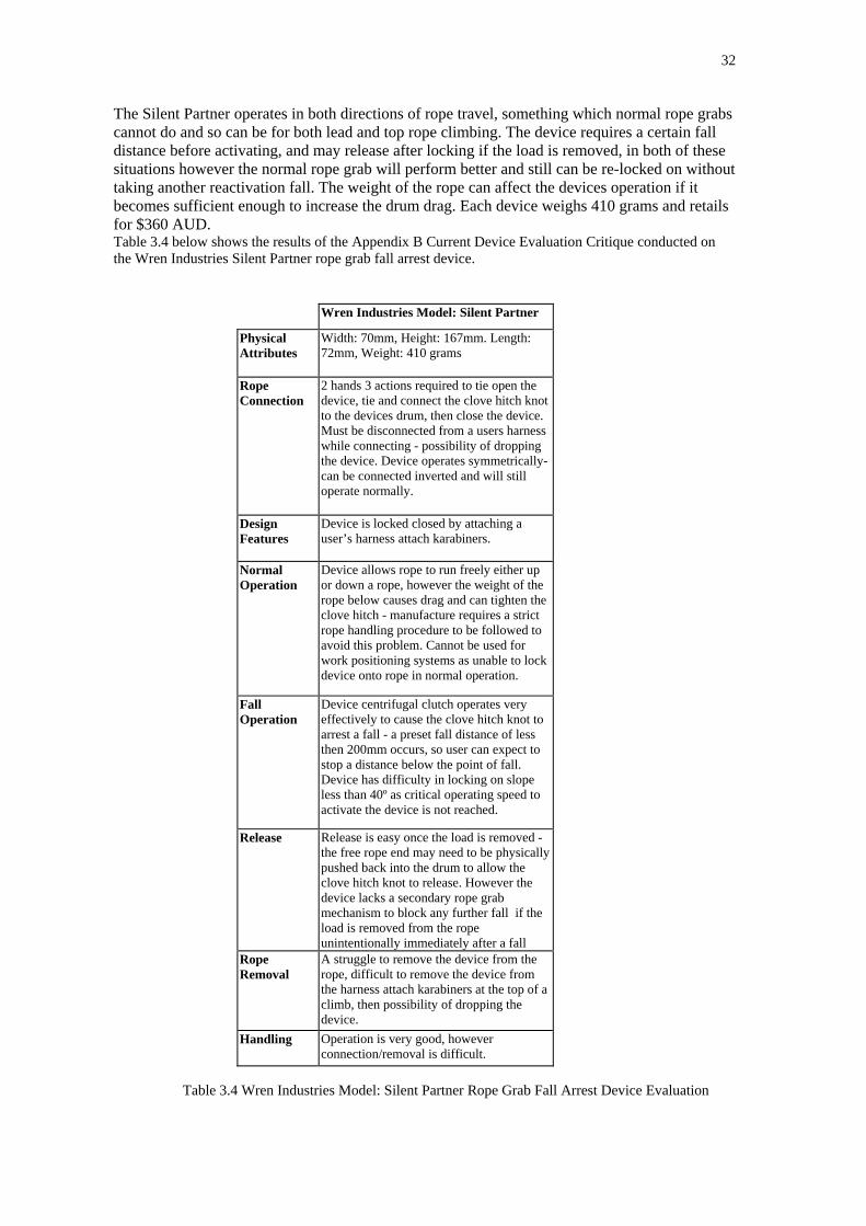
32
The Silent Partner operates in both directions of rope travel, something which normal rope grabscannot do and so can be for both lead and top rope climbing. The device requires a certain falldistance before activating, and may release after locking if the load is removed, in both of thesesituations however the normal rope grab will perform better and still can be re-locked on withouttaking another reactivation fall. The weight of the rope can affect the devices operation if itbecomes sufficient enough to increase the drum drag. Each device weighs 410 grams and retailsfor $360 AUD.Table 3.4 below shows the results of the Appendix B Current Device Evaluation Critique conducted onthe Wren Industries Silent Partner rope grab fall arrest device.
Wren Industries Model: Silent Partner
PhysicalAttributes
Width: 70mm, Height: 167mm. Length:72mm, Weight: 410 grams
RopeConnection
2 hands 3 actions required to tie open thedevice, tie and connect the clove hitch knotto the devices drum, then close the device.Must be disconnected from a users harnesswhile connecting - possibility of droppingthe device. Device operates symmetrically-can be connected inverted and will stilloperate normally.
DesignFeatures
Device is locked closed by attaching auser’s harness attach karabiners.
NormalOperation
Device allows rope to run freely either upor down a rope, however the weight of therope below causes drag and can tighten theclove hitch - manufacture requires a strictrope handling procedure to be followed toavoid this problem. Cannot be used forwork positioning systems as unable to lockdevice onto rope in normal operation.
FallOperation
Device centrifugal clutch operates veryeffectively to cause the clove hitch knot toarrest a fall - a preset fall distance of lessthen 200mm occurs, so user can expect tostop a distance below the point of fall.Device has difficulty in locking on slopeless than 40º as critical operating speed toactivate the device is not reached.
Release Release is easy once the load is removed -the free rope end may need to be physicallypushed back into the drum to allow theclove hitch knot to release. However thedevice lacks a secondary rope grabmechanism to block any further fall if theload is removed from the ropeunintentionally immediately after a fall
RopeRemoval
A struggle to remove the device from therope, difficult to remove the device fromthe harness attach karabiners at the top of aclimb, then possibility of dropping thedevice.
Handling Operation is very good, howeverconnection/removal is difficult.
Table 3.4 Wren Industries Model: Silent Partner Rope Grab Fall Arrest Device Evaluation

33
3.3. Issues Identified From the Critique Evaluation
• Specific Design Advantages:
• Automatic multi direction fall arrest blocking is provided by the Silent Partner device.
• A two-handed action sequence is required to open and close the Cobra device.
• Simple and intuitive design of the Ascension device allows easy rope connection.
• Cam profile of the Gibbs Type 2 device allows for good rope jamming and once the load is removed, the cam can be quickly released from the rope.
• Specific Design Deficiencies:
• Rugged oversized steel construction of the Cobra limits the size and type of safety ropeto uncommon rope types.
• Thin frame sections of the Ascension and Gibbs devices may limit the anticipated fallforces generated in a fall as the frames may distort under the dynamic loads.
• Difficult rope connection for the Silent Partner may allow the device to be
dropped due to the user cannot clip the device to his harness during the device setup
• No secondary rope blocking provided on the Silent partner – if the load is removed the locking knot can be quickly released and the device will allow a second fall/lock sequence to occur.
3.4. Chapter Conclusion
The evaluation critique has allowed direct in service comparisons between the four designs andhas identified several advantages and disadvantages for each of the four devices when used asType 1 back up rope grabs.
The critique tables developed for each of the four devices in this chapter have been grouped together as Appendix B which has been used to provide the objective basis for thedesign considerations for the fall arrest device.

Chapter 4. Design Criteria for the Research Project Back Up Fall Arrest Device
4.1. Introduction.
4.2. Design Considerations.
4.3. Chapter Conclusion.

34
Chapter 4. Design Criteria for the Research Project Back UpFall Arrest Device
4.1. Introduction
This chapter describes the criteria that was used as the basis for the Research Project Back UpFall Arrest Device design using information gained from the literature review in Chapter 2 andthe device evaluation critique in Chapter 3.
4.2. Design Considerations
By identifying limitations and positive features from the literature review and evaluation critiqueseveral specific issues can be improved in both design and application to eliminate thesedeficiencies and to combine the positive features for making the devices safer for the user. Thespecific areas are:
• Issues Arising from the Literature Review and Current Fall Arrest Device Evaluation Critique.
• Intended use of the device.
• Anticipated loads that will be placed on the device.
• Minimize human error in connection to the safety rope and operation of the device.
• Method of device actuation.
• Method of rope blocking that ensures the device remains blocked after the fall arrest load isremoved.
4.2.1. Issues Arising from the Literature Review and Current Fall Arrest Device Evaluation Critique
Several ideas arising out of the literature review have been considered on how they will affect thespecific areas listed above in the Design Consideration, these ideas include:
• Manageable size and weight for handling.
• To ensure rope connection is simplified.
• Allowing connection/removal while attached to a user’s harness to avoid dropping the device.
• Use of deliberate hand actions to open/close and latch the device.
• Visual conformation device is locked.
• Incorporate an automatic fall arrest function without user interaction, but allow for a userinput to manually release the blocking cams for work positioning.

35
• To limit the fall distance to reduce fall forces.
• Allow “hands free” climbing by user with no input required by user to reposition device.
• Be capable of locking in either fall direction on a rope.
• Be capable of use on horizontal static lines and able to be locked in either direction on thestatic line to allow user positioning across the horizontal line span.
4.2.2. Intended Use of the Device
A back up rope grab type 1 fall arrest device was chosen for the research project as an area thatwould benefit from a detailed use analysis and design review with two key areas of use identified:
• Fall Arrest – Automatic and Manual Operation Control:The fall arrest method is illustrated in Figure 2.3 (a) and Figure 2.3 (b) specifically for a workplace situation where the back up rope grab fall arrest device is attached to a safety rope thatis separate from the user's work rope. In recreation used the device would be connected to the work rope, as a separate safety ropeis not normally used.In the work place, the OH&S regulations and Australia/New Zealand Standards specify that afull body harness be worn by the user, this allows the back up fall arrest device to be eitherconnected to the front of the harness where the device is in easy reach of the user or it may beattached to the back of the harness out of the reach of the user. This will directly affect theintended use of the device; the device will be expected to be fully automatic for the backattach point, while the front attachment will allow for manual work positioning.For recreational use, sit harnesses are normally used, so the device is attached to the front ofthe harness allowing the user full control of the device functions.The fall arrest device may be connected to the users harness either directly or by a shortlanyard.
• Automatic Operation: The automatic function of the device will allow a user to ascend/descend the working ropewithout having to physically reposition the backup fall arrest device on the safety rope. Thefall arrest device will trail up and down the safety unless the user falls and the device inintended to automatically actuate and block the fall.The design criteria for this is to allow the user to have both hands free for climbing, thiscriteria is in direct opposition to the intent of the Australia/New Zealand Standard AS/NZ4488.1:1997 Industrial rope access systems Part 1: Specifications were the Standard requiresthat the back up fall arrest device must be manually repositioned by the user. The evaluationcritique of the current fall arrest devices has identified that the intent of the Standard in thisaspect could be a contributing factor in creating a fall particularly in recreational activitieswhere the user may fall off dubious hand/foot holds while having to physically reposition thefall arrest device – particularly when down climbing.
• Manual Operation - Work Positioning: Work positioning allows the device to be manually locked on a vertical or horizontalworking rope so that the user is restrained to allow work to be performed with a set area ofreach.

36
4.2.3. Anticipated Loads That Will Be Placed on the Device
To facilitate the stress analysis and device design, the maximum static load of 4kN designated inthe Australia/New Zealand Standard AS/NZ1891.3:1997 Industrial fall-arrest systems anddevices Part 3 Fall-arrest devices has been adopted as a key design parameter. This load has abasis of being four times the expected working load of an 80kg user weight with 20kg of safetyequipment and work equipment, then a safety factor of 2 is applied and the resulting mass totalmultiplied by the gravitational acceleration of g = 9.81 ms2.The dynamic test also designated in the Australia/New Zealand Standard AS/NZ1891.3:1997Industrial fall-arrest systems and devices Part 3 Fall-arrest devices has been adopted so that thedevice will limit the fall arrest distance to a maximum of 600 millimetres.
4.2.4. Minimize Human Error in Connecting to the Safety Rope and Operation of theDevice
• Connecting the device to the safety rope:Consideration for allowing simple safety rope connection while ensuring that the designwould allow the activation mechanism to operate and for the device to be structurally soundwas made. Much effort has been done in this area to ensure the step for connecting the rope isboth intuitive to the user and to eliminate any chance of incorrect rope connection occurs.This is accomplished by positioning the guide pullets and blocking cams so that it allows onlyone rope path to prevent the chance of any mis-rigging. When the frame is closed the guide pulleys, grab cams and frame have been located toencapsulate the rope to prevent the rope from being shifted out of the correct positionIn developing this, several different ideas were considered to allow for the ease of ropeconnection to the device. While the Silent Partner design of allowing the device frame halvesto be rotated about the common shaft to give access for rope connection is a simple solution,other considerations have affected the design of the frame. Consideration for prevented thedevice being dropped meant that the key hinge open frame feature of the Cobra device wouldbe a better alternative to ensure reduced human error in connecting the device to the rope andto allow the connection to the rope while still attached to the user’s harness without the needfor the device to be removed.
• How the device can be opened using two distinct hand actions:Consideration for this point was made so that two simple but independent sliding pin latchesthat lock the hinged frame half directly to the harness attach point/trigger link was made. Thesliding pins were designed to be spring loaded in the closed position:and to be held in double shear through the trigger link shafts while allowing the user tovisually confirm the device is locked. When closing the unit, the action for locking wasdesigned so that the user has to make a deliberate action to lock the frame closed – this is toprevent a user from assuming that the device has automatically “snapped” closed.Consideration for visual confirmation was made so that the user can quickly ascertain that thedevice is closed and locked.
• Operation Considerations:Careful consideration was made to ensure that the device is symmetric so that the device willoperate correctly if connected to the safety rope inverted - this feature creates a device thatperforms the multi-direction fall arrest function that only the Silent Partner is capable ofdoing.

37
4.2.5. Method of Device Actuation
For the device to operate as a multi-directional fall arrest unit consideration was given on how tosense a fall and then how to actuate the rope blocking mechanism. The fall speed sensing inertiamass concept used by the Wren Industries Silent Partner in activating the device was expanded toincorporate the variation in the friction forces generated by the safety rope sliding over the inertiaactivated clutch to trip the upper blocking cam and effectively block the user’s fall.
• How will the activating mechanism operate?Reviewing the patent document for the Wren Industries Silent Partner, design considerationswere made so that the clutch pulley mechanism would be sized to fit neatly into the clutchframe. Consideration for keeping the rope aligned as it travels through the device was madeby designing the clutch drum as a vee pulley with a rubber coated surface and machiningshallow vees in the two guide pulleys. In normal use the rope has some drag as it is moved along the rope due to rolling resistancefrom the rope riding over the clutch pulley and the two guide pulleys, the pulleys rotating onplain brass bushes, and the rope sliding against the blocking cam surfacesIn a fall situation, the clutch mechanism uses the rate of change of angular momentum of thepulley to impart a force impulse onto the device when the pulley lock rollers reach a setangular velocity. This angular velocity is determined by the centrifugal force generated as thetwo clutch rollers overcomes the return spring forces. When the angular velocity set point is reached - a roller at the lower position inside the clutchpulley moves out of its indent and moves along the ramp surface of the clutch pulley. Themovement of the lower roller moves the operating ring to force the upper roller out of itsindent and along the ramp. The rollers become wedged between the ramp surfaces and theclutch frame to jam the clutch pulley to the clutch frame.
Figure 4.1. Wren Industries Silent Partner Figure 4.2. Proposed Clutch MechanismUS Patent 4,941,548 Document Showing the two operating rollers (1)Showing one of three operating and springs (2) the two roller ramps (3)Rollers (50) and springs (52), the nylon actuating ring (4) all thetriangular roller ramps (48) driven by the vee pulley (5)driven by the rope drum (46)
1
32
4 5

38
The sudden locking of the clutch pulley causes the safety rope to drag over the rubber surfaceof the clutch pulley and to rapidly increase the retarding fall force experienced by the fallingdevice frame. This is due to the friction force induced between the rope now sliding over therubber surface is much larger than the rolling resistance experienced during by the ropewinding through the clutch pulley and guide pulleys in the unlocked position. The upper blocking cam is released by the trigger link that continues falling undergravitational acceleration relative to the frame. As the frame falls downwards at a slower rateof acceleration due to the retarding friction force, the trigger link trips the blocking camrelease to allow the spring loaded cam to rotate upwards to force the rope against the guidepulley. The cam wedge profile has been designed so that for a for each degree of rotation the contactsurface of cam is set at a constant wedge angle to cause the cam to effectively block the ropeagainst the guide pulley. The cam shafts were positioned so that for a certain range ofintended rope diameters of 9 to 11 millimetres, would be blocked against the cam with someremaining cam travel. The cam was sized so that the cam could not be dragged all the waythrough and past the guide pulleys.
• Resetting of the device after activation:Design consideration was made to the grab cam wedge angle so that the cam would provideeffective blocking, however too fine an angle and the cam becomes too difficult to releasefrom the rope, conversely too coarse an angle the effective blocking is reduced. An effectivewedge angle of 10° was selected as a trial for the prototype cams.The cam size and profile was designed to allow for the cam to be latched in the open positionto allow for the rope to be connected. When the cam was either manually released oractivated in a fall, the rotated cam profile protrudes from the device frame so the user canvisually see confirm the device has been activated.The device is reset by removing the load from the device and then pushing the cam edge backto the open position – this is confirmed by a “click” as the cam is engaged by the releasemechanism.
• Rope drag and locating the guide and clutch pulleys:To reduce the overall rope drag through the device and to ensure that the rope movingthrough the device would spin up the clutch pulley - a compromise was made to ensure aneffective contact angle between the rope and the clutch pulley and reducing the amount ofinduced friction in the rope as it is fed over the guide pulleys/clutch pulley. The guide pulleyswere also positioned to allow for the grab cams to swing clear of the clutch pulley whenactivated. The guide pulley location was positioned adjacent to the frame hinges so that thedevice would allow the rope to run on the pulleys only and clear of the cam surfaces – theadvantage of this allows the device to be used as a runner on a horizontal safety rope.
4.2.6. Method of Rope Blocking That Ensures the Device Remains Blocked After the FallArrest Load Is Removed
One drawback of the Silent Partner design is its inability for the device to remain blocked afterthe fall arrest load is removed. Removing the fall load allows the clove hitch knot used to block afall to quickly release. It is unfortunate that to re-block the device onto the rope again, a rapidmanual pull on the safety rope must be done – or a second fall must occur to carry out theblocking.
The simpler fall arrest devices evaluated retain this ability of having the blocking cam engaged onthe safety rope to prevent any further movement down the rope. In particular the Ascension

39
blocking cam is spring loaded against the rope allowing rapid re-blocking, while the Gibbs andCobra devices are quite easy to reset the cam back onto the safety rope.
4.2.7. Design Evaluation
Several ideas were trialed in order to establish what prototype layout could best accomplish eachof the design criteria without adding constraints that may increase the device complexity orphysical size.Several of these ideas were explored using cardboard models and the software packageSOLIDWorks to work out what features were feasible for use.
Figures 4.3 and 4.4 show the prototype evaluations explored using physical and virtual modelingtechniques to determine:• Component size, rope.• Rope connection possibilities.• Device actuation.• Rope blocking.
In the case of this models shown below all ideas were rejected due to difficulty inserting the rope,possibility of dropping the device while connecting and limited manual control, however thedevice would have remained blocked after the load was removed.
Figure 4.3. Cardboard and Polystyrene Modeling of a Rotating Frame Idea with Integral Blocking Cams on the Inertia Pulley

40
Figure 4.4 The SOLIDworks Virtual Model of the Initial Design Idea.The blue block is a rope guide to prevent the rope from shifting.
4.3. Chapter Conclusion
This chapter has allowed a descriptive concept of the Back Up Type 1 Fall Arrest Device modelto be developed using the information gained from the literature review of Chapter 2 and theCurrent Fall Arrest Device Evaluation Critique carried out in Chapter 3.While the design concept appears to be a large brief, the next chapter shows that several of theideas have accomplished the intent of several of the points simultaneously by using logical designtechniques. The next chapter describes the process of converting the work of this chapter into astress analyzed virtual prototype model ready for the manufacturing process.

Chapter 5. Prototype Design and Manufacture
5.1. Introduction.
5.2. Material Selection.
5.3. Hand Stress Analysis Calculations for Key Prototype Components.
5.4. SOLIDworks Prototype Modeling of a Fall Arrest Prototype.
5.5. Finite Element Stress Analysis of Prototype Design Components.
5.6. Manufacturing the Prototype Components.
5.7. Chapter Conclusion.

41
Chapter 5. Prototype Design and Manufacture5.1 Introduction
This chapter uses the proscriptive design that was developed in Chapter 4 to conduct stressanalysis of key components for determining components sizes based on the materials selected formanufacture, then to construct a virtual model using to allow for sizing and componentinteraction.Stress analysis of the design was conducted using both ANSYS 5.5 ED and COSMOSxpressfinite element analysis software packages to help verify the manual “Back of the Envelope”calculations. Virtual modeling was carried out using the Solidworks program package to put together workablecomponent and assembly models of the design.Production drawings were developed from the Solidworks models to allow the physical prototypecomponents to be manufactured on non-CNC lathe and milling machines.
5.2 Material Selection
The materials used for manufacturing the prototype components from have been selectedprimarily due to availability. All the materials used are of commercial grade and are obtainable inthe Singapore market. The reasoning for the material selection are based:
• Purchase cost price.
Material Size Cost (AUD)Aluminium Alloy 6063-T6 Rod 75mm Ø x 300mm length $15.00 (Singapore) Bar 20mm x 150mm x 300mm length $36.00 (Singapore)
Stainless Steel AISI 302 Rod 20mm Ø x 300mm length $42.00 (Singapore)
Yellow Brass 60/40 Rod 20mm Ø x 100mm length $6.00 (Singapore)
Nylon 66 Rod 50mm Ø x 100mm length $12.00 (Sydney)
Table 5.1. Purchase Costs of Prototype Materials May 2004
• Commercially available materials.The engineering supply shops in Singapore supply a wide range of wrought aluminiumalloys, however the for practical purposes the decision to cap the cost of prototyping haslimited the material choice to either 6061-T6 or 6063-T6. 6063-T6 was selected due to bettermachineability and higher yield strength, improved corrosion resistance and higher materialhardness than 6061-T6.
• Relative ease of machineability.This criteria is important for the AISI 302 stainless steel used as several of the machine toolsused for the manufacture of components would experience some difficulty in performing themachining process due to the harness properties of other available grades of stainless steel.For the alumimiun alloy 6063-T6, the material free machines with much less chip welding tothe cutting tools than 6061-T6.Known material properties for stress analysis using Appendix B, Mechanics of Materials,Beer & Johnston 2nd Edition 1992 and Juvinall R. and Marshek, K. ‘Fundamentals ofMachine Component Design’, 2nd Edition, Wiley 1991, P.772.
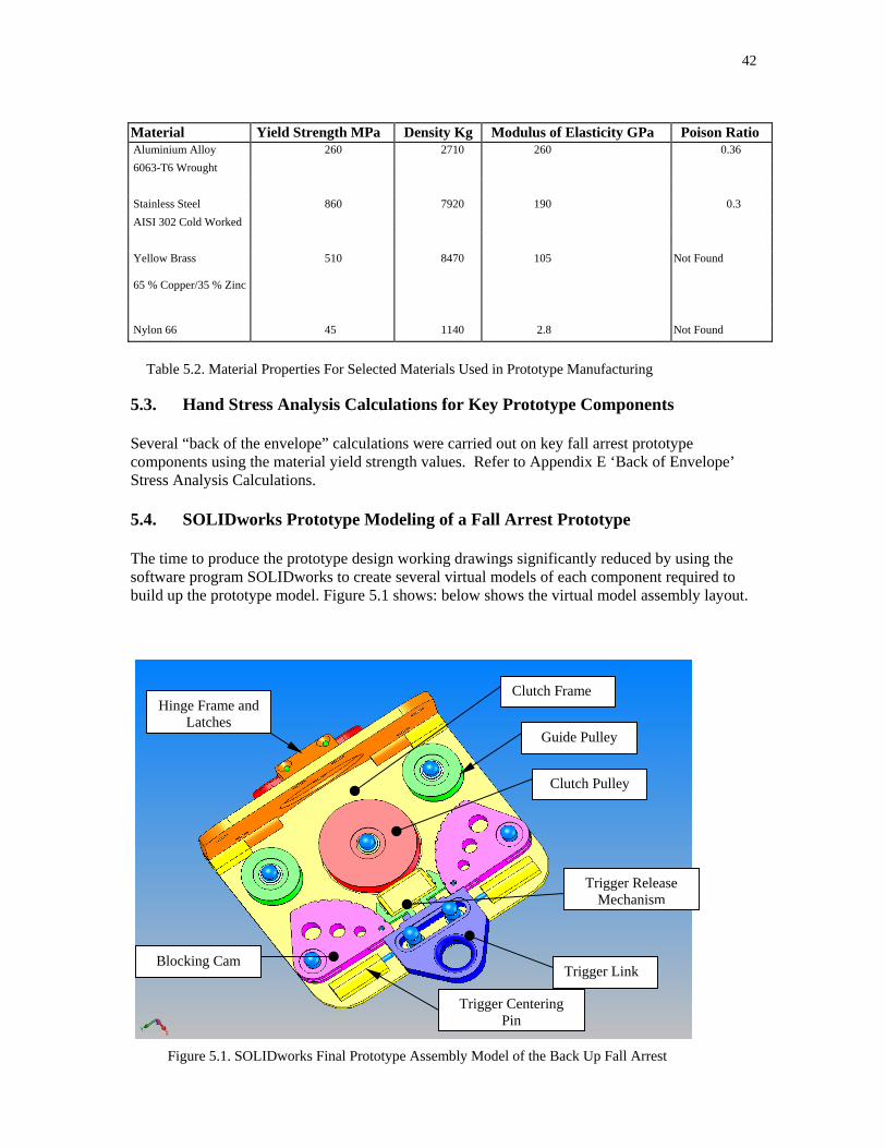
42
Material Yield Strength MPa Density Kg Modulus of Elasticity GPa Poison Ratio Aluminium Alloy 260 2710 260 0.36 6063-T6 Wrought
Stainless Steel 860 7920 190 0.3 AISI 302 Cold Worked
Yellow Brass 510 8470 105 Not Found
65 % Copper/35 % Zinc
Nylon 66 45 1140 2.8 Not Found
Table 5.2. Material Properties For Selected Materials Used in Prototype Manufacturing
5.3. Hand Stress Analysis Calculations for Key Prototype Components
Several “back of the envelope” calculations were carried out on key fall arrest prototypecomponents using the material yield strength values. Refer to Appendix E ‘Back of Envelope’Stress Analysis Calculations.
5.4. SOLIDworks Prototype Modeling of a Fall Arrest Prototype
The time to produce the prototype design working drawings significantly reduced by using thesoftware program SOLIDworks to create several virtual models of each component required tobuild up the prototype model. Figure 5.1 shows: below shows the virtual model assembly layout.
Guide Pulley
Clutch Pulley
Trigger Link
Hinge Frame andLatches
Blocking Cam
Trigger Centering
Trigger ReleaseMechanism
Clutch Frame
Pin
Figure 5.1. SOLIDworks Final Prototype Assembly Model of the Back Up Fall Arrest

43
The SOLIDworks virtual models allowed checking of component and assembly lay out in thefollowing areas:• Component dimensions.• Critical geometric relationships between components. • Fits and clearances of fixed and moving components and to highlight on areas of possible
interference between components. • Component mass.By building up an assembly model – the inter-relationships between component could be checkedfor physical layout, fits, clearances and the problems of component interference. Figure 5.2 belowhighlights an exploded view of the 48 components used to make up the fall arrest device- eachhave been checked for correct clearance to the other components in the assembly. TheSOLIDworks component model sketches and production drawings have been compiled asAppendix H.
Figure 5.2. SOLIDworks Exploded View of the Back Up Fall Arrest Device Assembly
5.4.1 Clutch Frame, Hinge Frame and Latch Design Justification
• The clutch frame has been designed to be manufactured out of 6063-T6 aluminium alloy withoverall dimensions of 142 mm long by 113 mm width in order to house all the components.The physical size of the whole device is directly proportional to the rope diameter size rangeof 9mm to 11mm Ø. A modular design was used for the prototype that allow the individual components to bemounted by M5 countersunk machine screws and for this purpose a standard material sectionof 6mm was chosen to provide sufficient frame stiffness and support where the componentsattach. The manual stress calculations were used to verify the edge margins for the locationof the blocking cam and guide pulley shafts. A recessed boss housing for the clutchmechanism has been place in the approximate centre of the device, and two hinge supports

44
have been place one edge. It was anticipated that several areas of the frame can be “hollowedout” to reduce the overall weight without compromising the frame strength or stiffness.
• The hinge frame has been designed in tandem with the clutch frame to provide a enclosedunit by having the two components hinge together at one edge by a two section hinge withtwo M5 countersunk screws. All the supporting shafts pass through the hinge frame holeswhen the frames are locked closed so that each shaft is supported by both the clutch frameand hinge frame in double shear. Figure 5.3 below shows the rounded ends of each shaftpassing through the hinge frame.
• The two independent open/close latch mechanism has been designed as an integral block onthe hinge frame – the latches are designed as simple spring loaded –closed sliding cross pinsthat pass through a hole drilled in each trigger link shaft. The cross pins are placed in doubleshear by the hinge frame when the frame is closed. Two large simple rings have beenattached to the cross pins with 1mm Ø roll pins to allow a users finger to slide the cross pinsback. The latches have been designed so that the user must physically align the frame beforereleasing the cross pins to lock the device – this is to avoid a complacent user from assumingthat the device has “snapped closed by itself.
Figure 5.3. Hinge Frame in Closed and Latched Position: showing each shaft that passes through the hinge frame is supported
5.4.2 Clutch Pulley Mechanism Design Justification
While the design of the clutch mechanism is based on the Silent Partner Us Patent description, thedesign for the research project has used a simplified two surface parallel ramp that is milled intoone side of the clutch pulley instead of the triangular ramp described in the patent document. Theclutch pulley was designed to be turned from 6063-T6 aluminium alloy with an arbitrary size of
HingeScrew
Hinge Frame
Shafts Supportedin Hinge Frame
Latch Mechanism
Clutch Frame

45
47mmØ and the two rollers from AISI 302 stainless steel machined to 11mmØ and are straightknurled on their periphery to provide the keying grip into the clutch frame recessed boss. Theparallel ramp design allows for ease of milling machine set-up, and to improve the mechanismactuation a nylon actuating ring was designed to push the second roller into position by the firstroller when the required angular velocity was reached. The design has been worked out by trailand error in the manufacturing stage – particularly the spring rate as the complexity of themechanism is beyond the scope of the research project. Figure 4.2 Proposed Clutch Mechanismrefers.A simple interference fit plain bearing of yellow brass was considered for the clutch pulley as thea ball race bearing was considered not suitable due to possible problems with dust/fine particlecontamination generated by the clutch roller operation. The pulley is retained by an externalcirclip to the shaftTo keep the rope aligned on the clutch pulley a shallow vee groove was machined with anincluded flange angle of 130º, again this was found by trail and error. A simple natural rubbersleeve trimmed from a bicycle inner tube is glued to the lands of the pulley lands to provide thekey friction material to operate the trigger release mechanism (Chapter 4.2.5 Method of Actuationrefers). Positioning of the clutch roller in the frame was also a major consideration so that themovement of the rope passing through the device would spin the clutch pulley- again lineardeflection in the rope compared to the rope axis was found by trail and error, initial the high ropefriction in moving the device along the rope was thought to be high but was found to be similar tothe Silent Partner. A high rope drag could unnecessarily trip the device and release the blockingcams prematurely.
5.4.3 Blocking Cams and Guide Pulley Design Justification
The physical relationship between the blocking cams and the guide pulleys provides a designchallenge that must be fully effective when actuated to block the fall of a user yet they must offeras low a resistance to the movement of the rope as possible in normal mode of operation. • The guide pulley was set at an arbitrary 27mmØ in the preliminary design process and it was
found during the static load tests of being able to take the high component load exerted on bythe blocking cam. The guide pulleys are turned from 6063-T6 aluminium alloy. Guide pulleyswere inserted at this point in the frame to both reduce the rope drag and to place a setdeflection in order to effectively engage the rope with the clutch pulley. However it was anunknown if the blocking cams could effectively block a fall on a rotating/non fixed member.To reduce rolling element bearing brinelling due to the high component load, yellow brassinterference bearings were designed, with external circlips specified to hold the pulleys to theshafts. The AISI 302 stainless steel pulley shafts are designed to be 10mmØ at the pulleybearing with a set shoulder and reduced 8mmØ spigot that passes through the hinge frame –the shoulder is to prevent the hinge frame from closing too far and restricting the cams fromrotating.
• The blocking cam design has been geometry and location based to allow clearance for therope to slide past in the normal mode but to effectively block and to wedge rope in a fall. The cam base profile was constructed by drawing an epicyloid given a rolling circle and abase circle, refer to Appendix G, Figure G.1 for the drawing technique described by BoundyA.W. ‘Engineering Drawing’, 6th Edition McGraw Hill, 2000, p102.A wedge angle of 10º for the cam face against the rope was selected from experience withpost- fall cam release problems where devices have had to be cur from a rope after a seriousfall due to too fine a wedge angle, Chapter 4.2.5 refers. Initially, a range of 90º was selectedas the total cam travel from release to guide pulley contact, also considered with this was thata 9mmØ rope would be compressed to 5mm flat between. These dimensions where to ensurethat the 9mmØ rope would be blocked at about 80% of cam range, however it was found that

46
in the static load test even a thicker diameter rope was flatten to about 3mm and the camrotated almost the full travel distance, so a redesign was initiated to enlarge the cam effectiveradius. Provision was made for a helical wound activating spring on the cam shaft area togive the cam the required force and movement to block the rope. Also a 4mm wide slotmachined and a 3mmØ roll pin was inserted to provide for the cam release. Several lightningholes in the cam were found to be necessary to improve the response time for the upper camto rotate effectively into the rope when released, initially the cams were slow to moveupwards due to their weight/inertia acting against the helical springs trying to drive them.AISI 302 stainless shafts were designed with an 8mmØshaft at the bearing area and 6mmØ atthe hinge frame spigot, however during the initial static load test the spigot was found shearload distorted, so a redesign of just using 4mmØ straight was selected and found to beeffective, the cam is retained to the shaft by an external circlip.
5.4.4 Blocking Cam Release Mechanism and Trigger Attach Link Design Justification
• The trigger link performs two important tasks in the prototype fall arrest design. Firstly itattaches the user to the device and secondly it actuates the blocking cam release. The link hasbeen reverse engineered to actuate the release mechanism, then to fit neatly into the deviceand finally stress analyzed to ensure that it is strong enough to withstand the anticipatedloads. The link is milled from 6063-T6 aluminium alloy and designed to slide downwards inthe direction of a fall against the lower balance pin. The positioning of the two trigger linkshafts is to attach the trigger link to the frame, and to guide/limit the travel of the link so thedevice actuates in fall and then to securely hold the trigger link at the end of its travel.The two centering pins are to counteract the rope drag encountered when using the devicenormally. The pins hold the trigger link in a central spring balanced position unless the deviceis manually tripped by a sharp “tug” in either direction or is actuated in fall. The spring forcewas found by trial and error after assembly by using two helical wound springs placed inparallel: one inside the other to give a stiffer spring constant for the centering pins.The two trigger link shafts are machined from AISI302 stainless steel to 8mmØ and have a3mmØ perpendicular hole drilled through for the latch cross pins in the hinge frame.
• The blocking cam release mechanism comprises two simple sliding 6063-T6 plates that arespring loaded outwards that are limited in travel each by two 1mmØ roll pins. Themechanism allows only one blocking cam to be released in fall or both cams by manualrelease. When the trigger link is moved, the trigger link has two protruding milled “prongs:on one face that knocks the mating latch plates to release the blocking cam. The releasemechanism is located so that it holds both blocking cams against the balance pin housings –so that the cams give clearance for the rope in the normal position. Figure 5.4 below showsthe relationship between the trigger link, release mechanism and the blocking cams.

47
Figure 5.4. The Back Up Fall Arrest Prototype Design Shown With Trigger Link,
Trigger Release Mechanism and Blocking Cam in Fall Arrest Position
5.5. Finite Element Stress Analysis of Prototype Design Components
Finite Element stress analysis was carried out using COSMOSxpress on the SOLIDworks modelsand using the software package ANSYS5.5 Student Edition on several of the key components tohelp verify the “back of the envelope” calculations. Appendix F contains the resulting plots ofeach analysis carried.
5.6. Manufacturing the Prototype Components
The 48 components required for the working back up fall arrest prototype were machined usingnon-computer numerical controlled machines. The device was constructed in a modestlyequipped workshop in Sydney using:• HAFCO AL-60 lathe with centre height of 125mm• HAFCO HM-10 mini mill• ½ inch bench drill press• 100mm belt linisher• 8 inch bench grinderThe following series of photographs show the assembled prototype device before conducting theinitial static test to prove the blocking cam design:• Figure 5.5 shows the assembled unit with the test equipment connected to the device.• Figure 5.6 shows the initial blocking cam units found to be too small.• Figure 5.7 shows the initial trigger release mechanism that was resized to accommodate the
larger cams.• Figure 5.8 shows the clutch pulley and nylon actuating ring during a “trial and error”
approach to the design sizing of each component.
TriggerLink
moved totrip
position
Upper BlockingCam Released

48
Figure 5.5. Initial Assembly of Back Up Fall Arrest Prototype Device Set Up For The Static Design Verification Test. The photograph shows:
• How the safety rope is loaded inside the device.• The upper blocking cam tripped to block the rope against the upper
guide pulley
Figure 5.6. The Initial Blocking Cam Units Found to be Too Small
To Anchor
Static Test Load 4kN
Trigger RollPin
Slot for Trigger Catch

49
Figure 5.7. The Initial Trigger Release Mechanism: that was resized to accommodate the larger cams. The photograph also shows the blocking cam actuating spring and retaining circlip.
Figure 5.8. Clutch Pulley and Actuating Ring: showing the location of several features for a “trail and error” design evaluation of the operating sizes. A subsequent pulley was made with a smaller roller diameter to provide more effective pulley lock. The redesigned pulley and actuating ring were manufactured to fit the 11mmØ roller size.
Yellow Brass Bearing
Indent in Ramp for RollerCentralizing
Hole for Roller Spring
Cam Retaining Circlip
Actuating Ring

50
Table 5.3 below shows the time taken to manufacture each component and the quantity requiredto produce one prototype device.
Component Description Material Used Quantity Time To Manufacture EachComponent (Man Hours)
Clutch Frame 6063-T6 1 14Hinge Frame 6063-T6 1 10Clutch Pulley 6063-T6 1 8Clutch Pulley Bush Yellow Brass 1 2Clutch Shaft AISI 302 1 5Clutch Actuating Ring Nylon 66 1 4Clutch Spring A229 2 2Clutch Roller AISI 302 2 4Guide Pulley 6063-T6 2 10Guide Pulley Bush Yellow Brass 2 4Guide Pulley Shaft AISI 302 2 4Blocking Cam Lh 6063-T6 1 8Blocking Cam Rh 6063-T6 1 8Cam Shaft AISI 302 2 5Trigger Link 6063-T6 1 6Trigger link Shaft AISI 302 2 8Balance Pin AISI 302 2 5Balance Pin Adjust Set Screw AISI 302 2 2Trigger Plate 6063-T6 2 4Latch Handle 6063-T6 2 4Latch Pin AISI 302 2 3Latch Handle Set Screw AISI 302 2 2Lower Hinge Block 6063-T6 2 6Upper Hinge Block 6063-T6 2 6Trigger Housing 6063-T6 1 5Balance Pin Housing 6063-T6 2 7
Cam SpringLh
A229 1 2
Cam SpringRh
A229 1 2
Latch Spring A229 2 3BalanceSpring
A229 2 2
Total 48 233
Table 5.3 Component Manufacturing Quantity and Production Time
5.7. Chapter Conclusion
The resulting prototype back up fall arrest device design process has been a combination ofmeeting the design criteria by virtual modeling, coupled with review feedback from themachining and static testing processes.

51
The use of the Software page SOLIDworks improved the design considerably in allowing theneed for cardboard mock-up to be eliminated. The animation features of the software allowedmovement of the components to let interference checking to be done at the design stage withouthaving to resort to the reworking of components in the manufacturing stage. The virtual modelingallowed for many design ideas and changes to the model to be trialed quickly in the areas of sizeand positioning for each component so that each of the design criteria identified in Chapters 2, 3and 4 could be incorporated into a final design for machining.Consideration was done at each stage of the design to avoid complex shapes that would have beendifficult to machine. While several changes to the overall design were made during the machiningprocess and after the static test – the changes were essentially to increase component sizes as theoverall design was found to meet the project overall objectives. Static testing was conductedduring the manufacturing stage as part of the trial and error process to confirm that the blockingcams would work effectively as there would be little point in continuing to complete theprototype design if the device could not hold the static load. The final model was ready for the next stage of the project – the testing program defined inChapter 6.
Chapter 6. Testing and Result Analysis for the Back Up Fall Arrest Prototype
6.1. Introduction.
6.2. Types of Verification Testing Processes for the Back Up Rope Grab Fall Arrest Device.
6.3. Results of Testing.
6.4. Analysis of the Testing Completed to Date and Feedback for the Design Process.
6.5. Chapter Conclusion.

52
Chapter 6. Testing and Result Analysis for the Back Up FallArrest Prototype
6.1. Introduction
The testing program is to intended to verify the overall effectiveness of the prototype device ifpossible by helping to identify any short comings in the design and to provide feedback tohelp rectify or allow a redesign to address them.Testing of the prototype fall arrest device was designed to verify the blocking cameffectiveness under static and dynamic loading, and to verify the correct actuation of theclutch and cam release mechanisms. The static and dynamic load tests used are directly adopted from the Australia/New ZealandStandards reviewed in Chapter 2. However as the clutch and cam release mechanisms lieoutside the scope of the Australia/New Zealand Standards, a test was designed specifically inorder to verify that the device would operate as intended.The tests conducted to date were reviewed and the recommendations made have led toimmediate improvements to the final device design.
6.2. Types of Verification Testing Processes for the Back Up Rope Grab Fall Arrest Device
Testing of the back up fall arrest device is required to verify that the device if it is intended tobe used in the work place, will meet the Australia/New Zealand Standards requirementsbelow:• Type 1 fall arrest device static load testing as per Australian/New Zealand Standard
AS/NZ 4488.3:1997 Industrial rope access systems Part 3: Fall Arrest Devices.• Type 1 fall arrest device dynamic load testing as per Australian/New Zealand Standard
AS/NZ 4488.3:1997 Industrial rope access systems Part 3: Fall Arrest Devices.However, the design of the clutch and cam release mechanism will require that the testingprogram criteria will need to be expanded in range to prove several features of the proposeddevice that are outside the testing requirements of the Australian/New Zealand Standards forthe device. • To test the device for locking speed and arrested fall distance in vertical falls, a
verification test is required to confirm correct actuation. The test has its basis by usingrequirements for Type 2 fall arrest devices given in the Australian/New ZealandStandards AS/NZ 1891.3:1997 Industrial fall-arrest systems and devices Part3 Fall-arrestDevices and AS/NZ 4488.1:1997 Industrial rope access systems Part 1 Specification.
6.2.1. Static Load Testing for Back Up Rope Grabs and Ascender Devices
The test determines the integrity of a back up rope grab and its ability to avoid damage to arope when tested on a specific range of rope diameters with a set static load. Australia/New Zealand StandardAS/NZ4488.1:1997 Appendix A p10 when specifying the4kN test load says;
“test the expected maximum static service load of 2 kN multiplied by a factor of 2”
The test specifies a tensile test apparatus capable of applying the 4.0 kN load at a cross headspeed of 100 mm/minute using a test rope with a diameter of 10.5 to 11.0 mm are specified byboth AS/NZ1891 and AS/NZ 4488.The back up rope grab/ascender test specimen is attached to a rope that is tied to the test rigupper anchor and an over hand knot is tied 50mm in the rope below the device, then the testload is attached to the test specimen connection point. The test requires the 4kN load to beheld for at least 60 seconds, then the device is examined for signs of fracture or permanent

53
deformation and the rope is then examined or signs of damage. The steps are repeated fivetimes using the same test specimen and all results are recorded for the testing report. Figure6.1. below shows the static test set up.
Figure 6.1. Static Test Set Up for Testing Back Up Rope-grab/ Ascender Devices as per Australia/New Zealand StandardAS/NZ4488.1:1997 Appendix A
6.2.2. Dynamic Load Testing for Back-Up Rope Grabs
The test is used to test the integrity and performance of a back up rope grab when subjected toa dynamic load. The test simulated a free fall utilizing a falling mass and measuring the peakforce generated in the rope when the test specimen arrests the fall.The test mass of 100kg is required to be in the form of a vertical 200 mm diameter steelcylinder with a release mechanism to allow it to be released without imparting any initialvelocity.The test specimen is rigidly anchored to a test rig with an in-line force measuring instrumentcomplying to SAE J211/ 1Mar95 used to record the peak fall force in the rope. The test ropeof a diameter of 10.5 to 11.0 mm and 3.5 metres in length is used with a single overhand knottied at 3.0 metres below the top attach loop. Two test specimens that have been subjected andpassed the static test are to be used for the dynamic test. (Australia/New Zealand StandardAS/NZ4488.1:1997 Appendix B p12).The test procedure requires the mass to fall 600 mm from the release to when it applies loadto the test specimen. Figure 6.2. shows the dynamic test set below. The peak arresting forceon the rope is recorded and the specimen is examined for visible damage or permanentdeformation, then the rope is examined for damage and the extent of any slippage down therope.The test is repeated using a second test specimen and a fresh length of rope.
Upper Grip
Rope GrabSpecimen
ChainLanyard
Lower Grip
Test Rope
Single OverhandKnot
50 mm

54
Figure 6.2. Test Set Up for Dynamic Testing of Back Up Rope-gra Australia/New Zealand StandardAS/NZ4488.1:1997 Ap
6.2.3. Clutch and Cam Release Mechanism Verification Tes
The test is used to test the integrity and performance of a back upa simulated fall. The test simulated a free fall utilizing a falling msequence of fall forces generated in the rope when the test specimThis test has been formulated to verify the operation of the clutchand uses two parameters set by Australia/New Zealand StandardsIndustrial fall-arrest systems and devices Part3 Fall-arrest DeviceIndustrial rope access systems Part 1 Specification for a Type 2 fThe two parameters that define the test are:
• The maximum fall velocity is not to exceed 2.5 ms-1.• The maximum fall distance is limited to 0.6 m.
The test apparatus uses a load cell that reads in real time values tovelocity to be calculated for specific events in the fall sequence.The back up fall arrest device specimen is attached to overhead lodiameter of 10.5 to 11.0 mm and 3.5 metres in length is used withat one end and the other end is tied in a loop and then attached torope is connected to the specimen device and the device is releasethat does not impart any vertical velocity to the falling test mass.
Load Cell
300 mm
3000 mm
1000 mm
Chain Lany
Test Rope
Overhand Knot
Rope GrabSpecimen
bs as perpendix B
t
rope grab when subjected toass and measuring theen arrests the fall. and cam release mechanism AS/NZ 1891.3:1997s and AS/NZ 4488.1:1997all arrest device.
allow the maximum fall
ad cell. The test rope of a a single overhand knot tied
the 100N test load. The testd by a release mechanismThe sequence arresting
ard
100Kg Test Mass

55
forces on the rope, the sequence timing and maximum fall distances are recorded and thespecimen is examined for visible damage or permanent deformation, then the rope isexamined for damage and the extent of any slippage down the rope. The test is repeated andthen the rope is reversed and the tests repeated twice for the opposite side of the fall arrestmechanism. Figure 6.3 below show the set up of the test apparatus,
Figure 6.3. Test Set Up for the Back Up Fall Arrest Device Clutch and Cam Release Mechanism Verification Test
6.3. Results of Testing
The full test program of the back up fall arrest device was unfortunately curtailed due to thetheft of the device and several other pieces of testing equipment, Appendix C refers. Howeverseveral design ‘trial and error” tests were carried out to verify the operation of the camblocking, clutch mechanism and cam release mechanism. Static testing was conducted on testrig at the Single Rope Techniques factory at 9 Stanley Street Padstow, New South Wales.
3000 mm
10 Kg Test Mass
Zero PointDistance
Load Cell
Rope Grab Specimen
Attach Karabiner
Test Rope
Overhand Knot

56
6.3.1 Provisional Static Load Test – Blocking Cam Verification Check
Test Report For Back Up Fall Arrest Device SpecimenType of Test Conducted: Test Conditions: Test Date: Static Load Test 4000N Load 9th August 2004Test Report: To Verify Blocking Cam Effectiveness in Preparation For Dynamic Test #1
- Both rope blocking cams held the 4kN static load however the 11mm diameter static rope was blocked too far towards each cam end.
- No slippage down the rope was noticed on either side of the device during each test, and no damage to therope sheath was noted when the rope was removed from the device. On disassembly one cam shaft was
found to is shear distorted where the upper 6mm-diameter spigot passed through the hinge frame hole.
- The cams where found to be easily released from the rope when the 4kN load was removed and both cams were easily reset.
Table 6.1. Test Report for Back Up Fall Arrest Blocking Cam Verification 9th August 2004
6.3.2. Post Rework Static Load Test – Blocking Cam Verification Check
Test Report For Back Up Fall Arrest Device SpecimenType of Test Conducted: Test Conditions: Test Date: Static Load Test 4000N Load 12 August 2004Test Report: To Verify Blocking Cam Effectiveness in Preparation For Dynamic Test #2
- Both rope blocking cams held the 4kN static load, the 11mm diameter rope was blocked at approximately 80% of thecam surface.
- No slippage down the rope was noticed on either side of the device during each test, and no damage to therope sheath was noted when the rope was removed from the device. On disassembly no distortion or damage to thedevice was noted
- The cams where found to be easily released from the rope when the 4kN load was removed and both cams were easily reset.
Table 6. 2. Test Report for Back Up Fall Arrest Blocking Cam Verification 12th August 2004

57
6.3.3. Provisional Clutch and Cam Release Mechanism Test - Maximum Fall DistanceCheck
Test Report For Back Up Fall Arrest Device SpecimenType of Test Conducted: Test Conditions: Test Date: Clutch and Cam Release Verification Test 100N Load, Roller Spring Rate Checking 13 August 2004Test Report: To Determine Roller Spring Sizes by “Trial and Error” Approach, Load Cell Not Available For Test- Spring Diameter (mm) Left Hand Side of Device Fall Distance (m) Right Hand Side of Device Fall Distance (m) 0.32 1.10 1.05
1.11 1.05 0.28 0.77 0.71
0.79 0.71 0.19 0.55 0.60 0.55 0.59
- No slippage down the rope was noticed on either side of the device during each test, and no damage to therope sheath was noted when the rope was removed from the device. On disassembly slight “bedding in” of the clutchrollers was noted in the clutch frame and corresponding clutch pulley ramp surface.
- The cams where found to be easily released from the rope when the 100N load was removed and both cams were easily reset.
Table 6.3. Test Report for Back Up Fall Arrest Blocking Clutch and Cam Mechanism Maximum Fall Distance Check 13th August 2004
6.4. Analysis of the Testing Completed To Date and Feedback for the Design Process
The first static load test has highlighted two design deficiencies:• Firstly, the cam shaft suffered plastic deformation at the reduced diameter area where the 6 mmØ spigot passed through the 6.5 mmØ hole in the hinge frame. The deformation may bedue in part to the design was just above the calculated minimum diameter for the location ofDmin= 5.31 mm.• Secondly, the test also has identified that the cam surface contact point with the thicker 11
mmØ rope was too for back along the cam face.
The second static load test result confirmed the blocking cam redesign and rebuild were nowworking effectively and were able to be released easily form the rope after the load wasremoved.The clutch and cam release mechanism test carried was a “trial and error” test to see whateffect the changing of the roller springs would have on the total fall distance. Each reductionin spring material diameter reduced the fall distance.The results of the analysis for the initial static test led to reworking the prototype in two mainareas:• The cam shaft spigot diameter was redesigned to 8 mmØ and increasing the
corresponding hole size in the hinge frame to 8.5 mmØ. This has been done to prevent thecam shaft from suffering further plastic deformation due to the high shear load at thispoint by increasing the shaft diameter.
• The two blocking cams effective radii were increased by 2 mm, and the trigger releasemechanism resized to accommodate the larger cams.
The second static load test confirmed the size change was the correct step to undertake withthe blocked rope position change to only 80% of the cam surface used.

58
6.5. Chapter Conclusion
The testing conducted to date has proved that the blocking cam mechanism design is ready forthe dynamic load test as the device was found to be the capable of blocking the 4000N loadwith out any rope slippage or device distortion after the cam size was increased. Howevertesting on thinner diameter rope would have to be carried out to check if the cam re-sizing isadequate for using a 9 mmØ rope that has been specified in the design criteria of Chapter 4.
The results of achieving the 600mm maximum fall distance by a change in roller springdiameters/ spring constant has demonstrated that the device is capable of being adjusted tomeet the test criteria standard. Further testing using the load cell to ascertain the maximumfall velocity reached would have been preferable, however the static load test and the clutchand cam release test results to date have been quite satisfying to have achieved. Using load cell analysis would help to fine tune the device by determining if reducing theblocking cam moments of inertia could help in reducing the maximum fall velocity and inturn to limit the fall forces generated. By reducing the roller spring constant alone, the clutchmechanism may become too sensitive to linear movement of the rope and lead to nuisancetripping of the device in normal use. This area of testing will be crucial in finding a goodbalance between the clutch trip point and the inertial lag of the blocking cam movement.
For the stage that the device has reached, from a users perspective – the device has the right“feel” where it can be moved along a rope with out the feel of too much rope drag, and verylittle nuisance tripping occurs when the device is used for hands free climbing.

Chapter 7. Conclusion
7.1. Introduction.
7.2. The Research Project Objectives.
7.3. Achieving the Objectives.
7.4. Deficient Areas of the Back Up Fall Arrest Device.
7.5. Further Work for the Back Up Fall Arrest Device Concept

59
Chapter 7: Research Project Back Up Fall Arrest Device Conclusion7.1. Introduction
Several of the key objectives in the design, prototype building and testing of a new back up fallarrest device have been met by the undertaking of this research project.
7.2. The Research Project Objectives
The objectives specified in Chapter 1. Introduction and Appendix A Project Specification havebeen used a plan to achieve these key objectives. These key objectives have been to:
• Conduct a thorough literature review of the government legislation specifically pertaining toOccupational Health and Safety in the workplace for working at heights. To review accidentstatistics to establish if a needs basis for the new device is required to overcome deficienciesin the currently available equipment in use. To review Australia/New Zealand Standards andInternational standards for specific requirements of equipment in current use to establish thedesign and test criteria for the new device. To review fall arrest methods used in both thework place and in recreational areas.
• Conduct a thorough evaluation of current fall arrest equipment in use in the workplace and inrecreational areas to establish the strict requirements for a design basis that the new back upfall arrest device specifically has addressed.
• Examine the operating environment and uses that the back up fall arrest device would beexpected to be used in to establish the design requirements.
• Design and build a workable back up fall arrest prototype device using the strict requirementsformed from the literature review, the current fall arrest device critique and the designcriteria.
• Establish and conduct a test regime to prove or otherwise the prototype device, and tocritically evaluate the testing data for a design review.
7.3. Achieving the Objectives
The research project process has allowed a workable prototype back up fall arrest device to beconstructed that has met many of these key objectives. Specific requirements were identified in the Chapter 2 Literary Review and the Chapter 3 CurrentFall Arrest Device Review as deficiencies that have contributed to accidents or positive featuresdesigned to eliminate the possibility of human handling errors.Chapter 4 Design Criteria For the Back Up Fall Arrest Device, explored the requirements to bothimprove and incorporate the findings of Chapter1 and 2 and to examine what specific usesexpected of the device would influence the final design. Another important part of the designprocess was the examination of what operating principles would be used to actuate the device inorder to achieve the use requirements. The device uses a fall sensing mechanism that detects a falland is then actuated to bock the fall.The actual design and construction documented in Chapter 5 allowed for a series of conceptualideas to trialed by virtual modeling to establish the viability of the prototype design in meetingthe specific requirements before the components were manufactured. This included the designlayouts, material selection, stress analysis of key components and the fits and clearances ofassemblies.

60
After the prototype construction was completed, a series of proving tests were conducted to allowfor design confirmation, Chapter 6 documents this stage in the project. A three-stage set of testswere proposed to verify the prototype design.The tests used have a basis on the relevant Australia/New Zealand Standard for back up fall arrestdevices, however the prototype device actuating mechanism design lies outside the scope of thestandard, so a verification test method was established to confirm the fall detection sensing of thedesign.Immeadiate feedback for the initial tests while proving the design concepts, allowed for a re-evaluation of several design issues that were quickly incorporated into the design to produce amore workable unit, particularly in the size of the blocking cams.
Cessation of the testing program occurred after the device was stolen in Singapore.
The work to date had shown that the device was close to meeting each key objective particularly:
• The device was intuitive to use, with rope handling issues significantly reduced incomparison to the evaluated devices. - By making the device operate multi-directional it could not be connected to a rope
Inverted, thus eliminating a novice user’s greatest exposure to at use risk- Careful component positioning in the device eliminated mis-rope rigging.- The device allowed the safety rope to be connected while attached to a users harness to
prevent the device from being dropped particularly when at heights.- Single-hand, two distinct action unlocking/locking frame opening latches that must be
physically positioned open/closed that also provide visual confirmation.
• The device is adaptable for several uses, in direct comparison to existing devices, which aredesigned to accomplish one or more purposes only.- Allows for fall sensing and automatic rope blocking in the advent of a fall limiting the
fall distance to less than 600mm- Allows the user to be able to climb hands free as the device can trail the safety rope- The device can be manually activated so that it will block in one direction on a safety
rope to allow for work positioning, or to be used as an ascender to climb the rope.- The device’s strength allows it to be used on a horizontal safety line, and is capable of
being locked to prevent any movement in either direction on the safety line.
7.4. Deficient Areas of the Back Up Fall Arrest Device
Deficient areas of the device are related directly to the theft of the device, as there wasinsufficient time to reproduce a second prototype device.
• Completion of the verification testing, two key areas remain uncompleted to date- Completing the fall sensing mechanism testing to allow the maximum fall velocity to be ascertained. This will allow for inertia design review of the fall sensing mechanism components to optimize how they operate and also the inertia design review of the blocking cams to allow for a faster response time in order to reduce the maximum fall distance.- Dynamic Load Test. This is the second verification test required to ensure the blocking cams operate effectively and block a fall without any distortion to the device or any visible rope damage.

61
• Weight considerations. The prototype was purposely built from commercially available materials tokeep the project costs low, which however meant that thicker sections were required in orderto give sufficient component strength and stiffness. The prototype weight was 488 grams,something that was to be reduced by hollowing out of non-critical areas on the millingmachine.
7.5. Further Work for the Back Up Fall Arrest Device Concept
Several areas of interest were uncovered during the research project into a new back up fall arrestdevice.• The literate review uncovered several proposed and new commercial fall arrest devices
coming onto the market. Although several of these devices appear to address some of theareas that I have looked at, there are several areas that these new devices are deficient in.Namely, the need for multi directional blocking. It would appear that the new devices areintended for one direction only – which my project identified as a significant area foreliminating potential accidents.
• Use of exotic high strength and stiffness materials for construction to reduce component andoverall assembly weights. The weight reduction would be beneficial for two reasons:- less weight for a user to carry, with a less bulky sized device- reduced maximum fall distances due to improved inertial qualities of the device and
improved overall device strength.• Finding an improved understanding of the devices fall sensing and actuation mechanism –
unfortunately this has been outside the scope of this research project, however theunderstanding of the key concepts I feel may allow for accurate modeling that could improvethe device design in reducing the fall distances and overall fall forces generated. I have triedto explain the operation of the device in Chapter 4 and Appendix G
• The review of the Australia/New Zealand Standard 4488 Industrial Rope Access Systemsshould be carried out in a timely manner for the incorporation of this type of back up fallarrest device that is coming onto the market. At the moment the standard does not cover thistype of device for use in the work place. I feel that a review is now due particularly in viewthat the standard is quite restrictive in its scope for automatic safety fall arrest devices nowthat several manufacturers are selling proven devises.
• Taking out of a provisional patent. It has been suggested that I should go ahead and patent thework done to date and continue with the development of a workable commercially viableunit, however I took the decision not to take out a provisional patent. Like many people whouse fall arrest equipment recreationally, incremental advances in equipment development helpprevent accidents as several manufactures produce their designs and eventually find their wayinto work related areas. I hope this project has been one of these advances.

R.1
List of References
Material Used for Appreciation Research and References
Programs
ANSYS Version 5.5 Student Edition, 1998
Solid Works Studio 2004
COSMOSXpress 2004
Brochures, Manufacturer; No Author
Airlines Support Industries Australia Pty Ltd Brochure March 2004
Beal Ropes, ‘The Dynamic Company”. 2003 Catalogue
Boeing 747-400 Maintenance Manual, Boeing Proprietary, Unpublished 10 Feb 1996
Gibbs Products Ascender, ‘About Gibbs Ascenders’ Brochure 1978
Gibbs Products Ascender, ‘Spring Loading The Gibbs Ascender’ Brochure 1978
Petzl Ascension Brochure Aug 2001
Petzl 2002-2003 Catalogue
Petzl 2003 Professional (English) Catalogue
Petzl Rescucender Brochure 2001
Protecta International Technical Specifications “Cobra” Rope Grab AC202A Revision 122001
Silent Partner User’s Manual Wren Industries Unpublished, 2000
WingGrip User Manual. Rota Limited Revision4 Jan 2000
Government Publications, No Author
WorkCover NSW Worker Compensation Statistical Bulletin Section 2000/2001
Victorian Legislation and Parliamentary Documents Occupational Health and Safety(Prevention of Falls) Regulations 2003 S.R.No.121/2003
New South Wales WorkCover Authority, Code of Practice Safe Work on Roofs, Part 1 –Commercial and Industrial Buildings, gazetted 13 Aug 1993, commenced 1 Nov 1993
New South Wales WorkCover Authority, Code of Practice Safe Work on Roofs, Part 2 –Residential Buildings, gazetted 6 Dec, commenced 1 Mar 1997

R.2
New South Wales Government Occupational Health and Safety Regulation 2001
WorkCover Victoria Code of Practice – (No.28) – Prevention of Falls in GeneralConstruction 31 Mar 2004
Journals
Peterson B., ‘Canyon and Caves’ Number 3 1971)
Patents
United States Patent Number 4,253,218. Gibbs P. ‘Spring Loaded Ascender’. 3 March 1981
United States Patent Number 4,941,548. Blanchard M. ‘Fall Arresting Device For Climbers’17 July 1990
Standards, No Author
Australian /New Zealand Standard AS/NZ 1657 Fixed platforms, walkways, stairways andladders – Design construction and installation
Australian/New Zealand Standard AS/NZ 1891.3:1997 Industrial fall-arrest systems anddevices Part 3 Fall-arrest Devices
Australian/New Zealand Standard AS/NZ 1891.4:1997 Industrial fall-arrest systems anddevices Part 4: Selection, use and maintenance
Australian Standard 2424-1981 Plastic Building Sheets – General installation requirementsand design of roofing systems
Australian/New Zealand Standard AS/NZ 2550.10 Cranes - Safe use - Elevating workplatforms
Australian/New Zealand Standard AS/NZ 4488.1:1997 Industrial rope access systemsPart 1: Specifications
Australian/New Zealand Standard AS/NZ 4488.2:1997 Industrial rope access systemsPart 2: Selection, use and maintenance
Australian/New Zealand Standard AS/NZ 4488.3:1997 Industrial rope access systemsPart 3: Fall Arrest Devices
Australian Standard/New Zealand AS/NZ 4576 Guidelines for scaffolding
British Standard: Code of Practice for the Use of Safety Nets on Construction WorksCP93
British Standard: Personal protective equipment against falls from a height- Fall arrestsystems BS EN 363: 1993
British Standard: Personal protective equipment against falls from a height- Test methodsBS EN 364: 1993

R.3
European Standard EN 567 Mountaineering equipment, rope clamp, safetyrequirements and test method
Union Internationale des Association d”Alpinisme UIAA Standard: 126 Mountaineering andClimbing equipment: Rope Clamps. Jan 2004
Texts
Beer F. P. & Johnston E. R., ‘Mechanics of Materials’, 2nd Edition SI Units McGraw Hill1992.
Boundy A.W., ‘Engineering Drawing’, 6th Edition McGraw Hill, 2000.
Meriam J. & Kraige L., ‘Dynamics, Engineering Mechanics Volume 2, 3rd Edition, Wiley 1993.
Graydon D. Editor. ‘Mountaineering, The Freedom of The Hills’, Allen & Unwin, TheMountaineers, Seattle Washington USA 1992. Montgomery N. ‘Single Rope Techniques, a guide for vertical cavers’, Sydney SpeleologicalSociety Occasional Paper No 7, 1st Edition 1977.
Warild A. ‘Vertical, A Technical Manual for Cavers’, The Speleological Research CouncilLtd, Sydney, Australia. 1st Edition 1988.
Web Documents
Bossus P. History of the Union Internationale des Association d”Alpinisme UIAA undated,viewed 25 Apr 2004http://www.uiaa.ch./article/aspx?c=45&a=271
Sedgman, Iain B. Climbing Accidents in Australia !955 – 2004 viewed 23 May 2004http:/uob-community.ballarat.edu.au/~isedgman/climbing/Accidents.pdf
Storrick, Dr Gary Ascenders - Descender Collection 2001 viewed 24 Sep 2003http://www.storrick.cnchost.com/VerticalDeciesPage/Belay/SelfBelay…
Web Documents, No Author
CE Marking, Webportal for CE Marking & Regulatory Affairs, viewed 7 April 2004http://www.cemarking.net/article/articlrview/8/1/77
Protecta International Incorporated Website, viewed 21 Apr 2004http://www.protecta.com/world/products
Victorian WorkCover Authority WorkSafe Online, viewed 5 Mar 2004http://www.workcover.vic.gov.au/dir090/vwa/home.nsf/pages/so_safetybasics_falls
Figure References
Figure 2.1. Fixed Working PlatformsReference; Airlines Support Industries Australia Pty Ltd Brochure March 2004.

R.4
Figure 2.2. Work positioning system Reference: WingGrip User Manual. Rota Limited Revision 4 Jan 2000.
Figure 2.3.(a). Industrial rope access descent. Reference: Australian/New Zealand AS/NZ 4488.2:1997 Figure A1 p.16.
Figure 2.3.(b). Industrial rope access ascent.Reference; Australian/New Zealand AS/NZ 4488.2:1997 Figure A2 p.17.
Figure 2.4. Abseiling descent.Reference: Graydon D. Editor. ‘Mountaineering, The Freedom of The Hills’, Allen & Unwin,The Mountaineers, Seattle Washington USA 1992, Figure.8-1 p.13.7
Figure 2.5. Bottom belay braking. Reference: Petzl Rescucender Brochure 2001, Figure C1, p.111.
Figure 2.6. Frog method of ascender rope grab attachment. Reference: Montgomery N. ‘Single Rope Techniques, a guide for vertical cavers’, SydneySpeleological Society Occasional Paper No 7, 1st Edition 1977, Figure 138, p. 92.
Figure 2.7. Dynamic rope belay of a caver climbing a caving ladder to provide fall arrest.Reference: Petzl Rescucender Brochure 2001, Figure C3, p.111.
Figure 2.8. Rockclimbing fall arresting.Reference: Graydon D. Editor. ‘Mountaineering, The Freedom of The Hills’, Allen & Unwin,The Mountaineers, Seattle Washington USA 1992, Figure.7-1 p.109.
Figure 2.9.(a). The most severe fall. Reference: Beal Ropes, ‘The Dynamic Company”. 2003 Catalogue p.2.
Figure 2.9.(b). Less severe fall.Reference: Beal Ropes, ‘The Dynamic Company”. 2003 Catalogue p.2.
Figure 2.10. Top rope belayReference: Graydon D. Editor. ‘Mountaineering, The Freedom of The Hills’, Allen & Unwin,The Mountaineers, Seattle Washington USA 1992, Figure.7-1 p.109.
Figure 2.11. Solo Back Roped Rock ClimbingReference: Mark Blanchard, FALL ARREST DEVICE FOR CLIMBERS US Patent Number 4,941,548, 17 July 1990
Figure 2.12. Method of Roping Up for Glacier TravelReference: Lindsay Main, ‘Mountaincraft Manual 20’, New Zealand Safety Council Revised 2nd Edition 1987, Figure 94 p.p.146 & 147
Figure 3.1. Gibbs Ascender Model Type 2 rope grabReference: Christine Ho Collection, 03 May 2004.
Figure 3.2.(a). Aligning the components.Reference: Gibbs Products Ascender, ‘Spring Loading The Gibbs Ascender’ Brochure 1978.
Figure 3.2.(b). Inserting the quick release pin.Reference; Gibbs Products Ascender, ‘Spring Loading The Gibbs Ascender’ Brochure 1978.

R.5
Figure 3.3. The Protector “Cobra” Model AC202Arope-grabReference: Christine Ho Collection, 03 May 2004. Figure 3.4.(a). Two distinct hand actions used to unlock the “Cobra”. Reference: Christine Ho Collection, 03 May 2004.
Figure 3.4.(b). Frame is hinged open to accept the safety rope.Reference: Christine Ho Collection, 03 May 2004.
Figure 3.5. Petzl “Ascension” right handed rope-grab.Reference: Christine Ho Collection, 03 May 2004.
Figure 3.6.(a). Open cam and lock.Reference: Petzl Ascension Brochure Aug 2001.
Figure 3.6.(b). Place rope against rope in frame.Reference: Petzl Ascension Brochure Aug 2001.
Figure 3.6.(c). Release stop.Reference; Petzl Ascension Brochure Aug 2001.
Figure 3.7. Wren Industries “Silent Partner”.Reference: Petzl Ascension Brochure Aug 2001.
Figure 3.8.(a). Connecting the safety rope Reference: Silent Partner User’s Manual Wren Industries Unpublished, 2000Figure 1 p.11.
Figure 3.8.(b). The clove hitch is placedReference; Silent Partner User’s Manual Wren Industries Unpublished, 2000Figure 2 p.11.
Figure 4.1 Wren Industries Silent Partner DesignReference: Mark Blanchard, FALL ARREST DEVICE FOR CLIMBERS US Patent Number 4,941,548, 17 July 1990
Figure 4.2 Proposed Clutch MechanismReference: Alan Silva, SOLIDworks Unpublished, 03 August 2004.
Figure 4.3. Cardboard and Polystyrene Modeling of a Rotating Frame IdeaReference: Christine Ho Collection, 08 October 2004.
Figure 4.4 The SOLIDworks Virtual Model of the Initial Design Idea.Reference: Alan Silva, SOLIDworks 2004 Edition, Unpublished, 03 August 2004.
Figure 5.1 SOLIDworks Final Prototype Assembly Model of the Back Up Fall Arrest DeviceReference: Alan Silva, SOLIDworks 2004 Edition, Unpublished, 03 August 2004.
Figure 5.2. SOLIDworks Exploded View of the Back Up Fall Arrest Device AssemblyReference: Alan Silva, SOLIDworks 2004 Edition, Unpublished, 03 August 2004.
Figure 5.3. Hinge frame in closed and latched positionReference: Alan Silva, SOLIDworks 2004 Edition, Unpublished, 03 August 2004.

R.6
Figure 5.4. The Back Up Fall Arrest Prototype DesignReference: Alan Silva, SOLIDworks 2004 Edition, Unpublished, 03 August 2004.
Figure 5.5 Initial Assembly of Back Up Fall Arrest Prototype DeviceReference: Gary Silva Collection, 10 August 2004.
Figure 5.6. The Initial Blocking Cam Units Found to be Too SmallReference: Christine Ho Collection, 08 October 2004.
Figure 5.7. The initial trigger release mechanism that was resizedReference: Christine Ho Collection, 08 October 2004.
Figure 5.8. Clutch Pulley and Actuating RingReference: Christine Ho Collection, 08 October 2004.
Figure 6.1. Static test set up for testing back up rope-grab/ ascender devices. Reference: Australia/New Zealand StandardAS/NZ4488.1:1997 Industrial rope accesssystems Part 1: Specifications Appendix A, Figure A1 p.11.
Figure 6.2. Test set up for Dynamic testing of back up rope-grabs.Reference: Australia/New Zealand StandardAS/NZ4488.1:1997 Industrial rope accesssystems Part 1: Specifications Appendix B, Figure A2 p.14. Figure 6.3. Test set-up for the Clutch and Cam Release Mechanism Verification Test Reference: Alan Silva, Unpublished, 08 October 2004.
Figure E.1. Sketch of Back Up Fall Arrest Device In Orientated Fall Arrested PositionReference: Alan Silva, SOLIDworks 2004 Edition, Unpublished, 03 August 2004.
Figure E.2. Sketch of Blocking Cam and Guide Pulley LoadsReference: Alan Silva, Unpublished, 08 October 2004.
Figure E.3. Sketch of Free Body Diagram for Blocking Cam and Guide Pulley LoadsReference: Alan Silva, Unpublished, 08 October 2004.
Figure E.4. (a) Sketch of Cam Shaft LoadsReference: Alan Silva, Unpublished, 08 October 2004.
Figure E.4 (b) Sketch of FBD for Cam Shaft LoadsReference: Alan Silva, unpublished, 08 October 2004.
Figure E.5. (a) Sketch of Trigger Link Shaft Loads Reference: Alan Silva, Unpublished, 08 October 2004.
Figure E.5. (b) Sketch of FBD for Trigger Link Shaft Loads Reference: Alan Silva, Unpublished, 08 October 2004.
Figure E.6 Sketch of Clutch Shaft Loading Based on Rope Path Centre LineReference: Alan Silva, Unpublished, 08 October 2004.
Figure E.7. Sketch of FBD for Clutch Shaft Loading Reference: Alan Silva, Unpublished, 08 October 2004.
Figure E.8. Sketch of Shaft Groove Nomenclature for Grooved Shaft BendingReference: Alan Silva, Unpublished, 08 October 2004.

R.7
Figure E.9. Sketch of Shaft Cam Shaft Under Blocking Cam Distributed LoadReference: Alan Silva, Unpublished, 08 October 2004.
Figure E.10. (a) Shear Force Diagram for Blocking Cam ShaftReference: Alan Silva, Unpublished, 08 October 2004.
Figure E.10. (b) Bending Moment Diagram for Blocking Cam ShaftReference: Alan Silva, Unpublished, 08 October 2004.
Figure E.11. Bearing Stress for Clutch and Hinge Frames at Shaft HolesReference: Alan Silva, Unpublished, 08 October 2004.
Figure E.12. Trigger Link Section SketchReference: Alan Silva, Unpublished, 08 October 2004.
Figure E.13. Trigger Link Section A-A SketchReference: Alan Silva, Unpublished, 08 October 2004.
Figure E.14. Trigger Link Section B-B SketchReference: Alan Silva, Unpublished, 08 October 2004.
Figure E.15. Vector Force Diagram at Section B-BReference: Alan Silva, Unpublished, 08 October 2004.
Figure F.1 Constraints and Distributed Load Applied to Simplified Initial Cam Shaft ANSYS ModelReference: Alan Silva, ANSYS 5.5 ED, Unpublished, 16 October 2004.
Figure F.2 Initial Cam Shaft ANSYS SolutionReference: Alan Silva, ANSYS 5.5 ED, Unpublished, 16 October 2004.
Figure F.3 Constraints and Distributed Load Applied to Simplified Final Cam Shaft ANSYS ModelReference: Alan Silva, ANSYS 5.5 ED, Unpublished, 16 October 2004.
Figure F.4 Final Cam Shaft ANSYS SolutionReference: Alan Silva, ANSYS 5.5 ED, Unpublished, 16 October 2004.
Figure F.5 Constraints and Distributed Load Applied to Simplified Trigger Link ANSYS ModelReference: Alan Silva, ANSYS 5.5 ED, Unpublished, 16 October 2004.
Figure F.6 Final Trigger Link ANSYS SolutionReference: Alan Silva, ANSYS 5.5 ED, Unpublished, 16 October 2004.
Figure F.7 COSMOSxpress Trigger Link Plot showing the von Mises stress levelsReference: Alan Silva, COSMOSxpress 2004 Edition, Unpublished, 08 August 2004.
Figure F.8 Constraints and Distributed Load Applied to Simplified Hinge Frame ANSYS ModelReference: Alan Silva, ANSYS 5.5 ED, Unpublished, 15 October 2004.
Figure F.9 Final Hinge Frame ANSYS SolutionReference: Alan Silva, ANSYS 5.5 ED, Unpublished, 15 October 2004

R.8
Figure F.10 COSMOSxpress Hinge Frame Plot showing the von Mises stress levelsReference: Alan Silva, COSMOSxpress 2004 Edition, Unpublished, 08 August 2004.
Figure G.1 Clutch Mechanism NomenclatureReference: Alan Silva, Unpublished, 16 April 2004.
Figure G.2 (a) FBD of Forces on Upper RollerReference: Alan Silva, Unpublished, 16 April 2004.
Figure G.2 (b) FBD of Forces on Lower RollerReference: Alan Silva, Unpublished, 16 April 2004.
Figure G.3 Final Design Layout of Clutch MechanismReference: Alan Silva, SOLIDworks 2004 Edition, Unpublished, 03 August 2004.
Figure G.4 Vector Forces Generated by Rope Sliding Over the Locked Clutch PulleyReference: Alan Silva, Unpublished, 16 April 2004.
Figure G.5 Fall Forces Generated by Unlocked Falling Fall Arrest Device and Locked Fall Arrest DeviceReference: Alan Silva, Unpublished, 16 April 2004.
Figure H.1 Drawing Construction of an Epicycloid Reference: Boundy A.W. ‘Engineering Drawing’, 6th Edition McGraw Hill, 2000, p102.
Figure H.2 Initial Layout Sketch of Back Up Fall Arrest Device Design Reference: Alan Silva, Unpublished, 06 March 2004.
Figure H.3 SOLIDworks Model Back Up Fall Arrest Device Prototype AssemblyReference: Alan Silva, SOLIDworks 2004 Edition, Unpublished, 09 June 2004.
Figure H.4 SOLIDworks Model Back Up Fall Arrest Device Prototype Cam Left HandReference: Alan Silva, SOLIDworks 2004 Edition, Unpublished, 11 August 2004.
Figure H.5 SOLIDworks Model Back Up Fall Arrest Device Prototype Cam Right HandReference: Alan Silva, SOLIDworks 2004 Edition, Unpublished, 06 June 2004.
Figure H.6 SOLIDworks Model Back Up Fall Arrest Device Prototype Cam ShaftReference: Alan Silva, SOLIDworks 2004 Edition, Unpublished, 11 August 2004.
Figure H.7 SOLIDworks Model Back Up Fall Arrest Device Prototype Centering PinReference: Alan Silva, SOLIDworks 2004 Edition, Unpublished, 06 June 2004.
Figure H.8 SOLIDworks Model Back Up Fall Arrest Device Prototype Clutch SpringReference: Alan Silva, SOLIDworks 2004 Edition, Unpublished, 05 June 2004.
Figure H.9 SOLIDworks Model Back Up Fall Arrest Device Prototype Clutch FrameReference: Alan Silva, SOLIDworks 2004 Edition, Unpublished, 07 June 2004.
Figure H.10 SOLIDworks Model Back Up Fall Arrest Device Prototype Clutch PulleyReference: Alan Silva, SOLIDworks 2004 Edition, Unpublished, 08 June 2004.
Figure H.11 SOLIDworks Model Back Up Fall Arrest Device Prototype Clutch Pulley BushReference: Alan Silva, SOLIDworks 2004 Edition, Unpublished, 07 June 2004.

R.9
Figure H.12 SOLIDworks Model Back Up Fall Arrest Device Prototype Clutch RollerReference: Alan Silva, SOLIDworks 2004 Edition, Unpublished, 07 June 2004.
Figure H.13 SOLIDworks Model Back Up Fall Arrest Device Prototype Clutch ShaftReference: Alan Silva, SOLIDworks 2004 Edition, Unpublished, 06 June 2004.
Figure H.14 SOLIDworks Model Back Up Fall Arrest Device Prototype Guide PulleyReference: Alan Silva, SOLIDworks 2004 Edition, Unpublished, 07 June 2004.
Figure H.15 SOLIDworks Model Back Up Fall Arrest Device Prototype Guide Pulley BushReference: Alan Silva, SOLIDworks 2004 Edition, Unpublished, 08 June 2004.
Figure H.16 SOLIDworks Model Back Up Fall Arrest Device Prototype Guide Pulley ShaftReference: Alan Silva, SOLIDworks 2004 Edition, Unpublished, 06 June 2004.
Figure H.17 SOLIDworks Model Back Up Fall Arrest Device Prototype Hinge FrameReference: Alan Silva, SOLIDworks 2004 Edition, Unpublished, 08 June 2004.
Figure H.18 SOLIDworks Model Back Up Fall Arrest Device Prototype HandleReference: Alan Silva, SOLIDworks 2004 Edition, Unpublished, 08 June 2004.
Figure H.19 SOLIDworks Model Back Up Fall Arrest Device Prototype Handle Set ScrewReference: Alan Silva, SOLIDworks 2004 Edition, Unpublished, 07 June 2004.
Figure H.20 SOLIDworks Model Back Up Fall Arrest Device Prototype Latch PinReference: Alan Silva, SOLIDworks 2004 Edition, Unpublished, 08 June 2004.
Figure H.21 SOLIDworks Model Back Up Fall Arrest Device Prototype Clutch Actuating RingReference: Alan Silva, SOLIDworks 2004 Edition, Unpublished, 06 June 2004.
Figure H.22 SOLIDworks Model Back Up Fall Arrest Device Prototype Trigger Adjustment Set ScrewReference: Alan Silva, SOLIDworks 2004 Edition, Unpublished, 06 June 2004.
Figure H.23 SOLIDworks Model Back Up Fall Arrest Device Prototype Trigger CatchReference: Alan Silva, SOLIDworks 2004 Edition, Unpublished, 11 August 2004.
Figure H.24 SOLIDworks Model Back Up Fall Arrest Device Prototype Trigger LinkReference: Alan Silva, SOLIDworks 2004 Edition, Unpublished, 11 August 2004.
Figure H.25 SOLIDworks Model Back Up Fall Arrest Device Prototype Trigger Link ShaftReference: Alan Silva, SOLIDworks 2004 Edition, Unpublished, 06 June 2004.
Drawing References
Drawing: SOLIDworks Model Back Up Fall Arrest Device Prototype AssemblyReference: Alan Silva, SOLIDworks 2004 Edition, Unpublished, 09 June 2004.
Drawing: SOLIDworks Model Back Up Fall Arrest Device Prototype Cam Left HandReference: Alan Silva, SOLIDworks 2004 Edition, Unpublished, 11 August 2004.
Drawing: SOLIDworks Model Back Up Fall Arrest Device Prototype Cam Right HandReference: Alan Silva, SOLIDworks 2004 Edition, Unpublished, 06 June 2004.

R.10
Drawing: SOLIDworks Model Back Up Fall Arrest Device Prototype Cam ShaftReference: Alan Silva, SOLIDworks 2004 Edition, Unpublished, 11 August 2004.
Drawing: SOLIDworks Model Back Up Fall Arrest Device Prototype Centering PinReference: Alan Silva, SOLIDworks 2004 Edition, Unpublished, 06 June 2004.
Drawing: SOLIDworks Model Back Up Fall Arrest Device Prototype Clutch SpringReference: Alan Silva, SOLIDworks 2004 Edition, Unpublished, 05 June 2004.
Drawing: SOLIDworks Model Back Up Fall Arrest Device Prototype Clutch FrameReference: Alan Silva, SOLIDworks 2004 Edition, Unpublished, 07 June 2004.
Drawing: SOLIDworks Model Back Up Fall Arrest Device Prototype Clutch PulleyReference: Alan Silva, SOLIDworks 2004 Edition, Unpublished, 08 June 2004.
Drawing: SOLIDworks Model Back Up Fall Arrest Device Prototype Clutch Pulley BushReference: Alan Silva, SOLIDworks 2004 Edition, Unpublished, 07 June 2004.
Drawing: SOLIDworks Model Back Up Fall Arrest Device Prototype Clutch RollerReference: Alan Silva, SOLIDworks 2004 Edition, Unpublished, 07 June 2004.
Drawing: SOLIDworks Model Back Up Fall Arrest Device Prototype Clutch ShaftReference: Alan Silva, SOLIDworks 2004 Edition, Unpublished, 06 June 2004.
Drawing: SOLIDworks Model Back Up Fall Arrest Device Prototype Guide PulleyReference: Alan Silva, SOLIDworks 2004 Edition, Unpublished, 07 June 2004.
Drawing: SOLIDworks Model Back Up Fall Arrest Device Prototype Guide Pulley BushReference: Alan Silva, SOLIDworks 2004 Edition, Unpublished, 08 June 2004.
Drawing: SOLIDworks Model Back Up Fall Arrest Device Prototype Guide Pulley ShaftReference: Alan Silva, SOLIDworks 2004 Edition, Unpublished, 06 June 2004.
Drawing: SOLIDworks Model Back Up Fall Arrest Device Prototype Hinge FrameReference: Alan Silva, SOLIDworks 2004 Edition, Unpublished, 08 June 2004.
Drawing: SOLIDworks Model Back Up Fall Arrest Device Prototype HandleReference: Alan Silva, SOLIDworks 2004 Edition, Unpublished, 08 June 2004.
Drawing: SOLIDworks Model Back Up Fall Arrest Device Prototype Handle Set ScrewReference: Alan Silva, SOLIDworks 2004 Edition, Unpublished, 07 June 2004.
Drawing: SOLIDworks Model Back Up Fall Arrest Device Prototype Latch PinReference: Alan Silva, SOLIDworks 2004 Edition, Unpublished, 08 June 2004.
Drawing: SOLIDworks Model Back Up Fall Arrest Device Prototype Clutch Actuating RingReference: Alan Silva, SOLIDworks 2004 Edition, Unpublished, 06 June 2004.
Drawing: SOLIDworks Model Back Up Fall Arrest Device Prototype Trigger Adjustment Set ScrewReference: Alan Silva, SOLIDworks 2004 Edition, Unpublished, 06 June 2004.
Drawing: SOLIDworks Model Back Up Fall Arrest Device Prototype Trigger Catch

R.11
Reference: Alan Silva, SOLIDworks 2004 Edition, Unpublished, 11 August 2004.
Drawing: SOLIDworks Model Back Up Fall Arrest Device Prototype Trigger LinkReference: Alan Silva, SOLIDworks 2004 Edition, Unpublished, 11 August 2004.
Drawing: SOLIDworks Model Back Up Fall Arrest Device Prototype Trigger Link ShaftReference: Alan Silva, SOLIDworks 2004 Edition, Unpublished, 06 June 2004.