University of Southern Queensland Faculty of Engineering...
140
University of Southern Queensland Faculty of Engineering & Surveying Enabling Voice Calls via a Wireless Broadband Router A dissertation submitted by Adam Jones in fullment of the requirements of ENG4112 Research Project towards the degree of Bachelor of Engineering (Computer Systems) Submitted: October, 2009
Transcript of University of Southern Queensland Faculty of Engineering...
University of Southern Queensland
Faculty of Engineering & Surveying
Enabling Voice Calls via a Wireless Broadband Router
A dissertation submitted by
Adam Jones
in fulfilment of the requirements of
ENG4112 Research Project
towards the degree of
Bachelor of Engineering (Computer Systems)
Submitted: October, 2009
Abstract
Wireless networks are evolving rapidly, enabling services that until recently were al-
most exclusively bound to wired environments. With improvements to link quality,
bandwidth and network management (Wireless Mesh Networks), the rapid growth and
popularity of wireless networks is only going to continue.
With these improvements, opportunities to provide services such as Voice over Internet
Protocol (VoIP) are becoming feasible. The LinkSys WRT54GL wireless broadband
router is a cheap, yet powerful device that is able to run customised software on top of
routing data wirelessly.
Wireless Mesh Networks, VoIP software and the WRT54GL will be combined in this
Thesis to allow for a simple yet robust telephone network to exist in parallel with
traditional data networking.
It is envisioned that the telephone network will be able to create and maintain a tele-
phone network automatically. To enable this, additions to freely available VoIP soft-
ware will be made and a decentralised telephone network will exist entirely on wireless
routers.
A critical analysis will be carried out on all aspects of this Thesis and the feasibility
and practicality of such a system will be investigated and presented.
University of Southern Queensland
Faculty of Engineering and Surveying
ENG4111/2 Research Project
Limitations of Use
The Council of the University of Southern Queensland, its Faculty of Engineering and
Surveying, and the staff of the University of Southern Queensland, do not accept any
responsibility for the truth, accuracy or completeness of material contained within or
associated with this dissertation.
Persons using all or any part of this material do so at their own risk, and not at the
risk of the Council of the University of Southern Queensland, its Faculty of Engineering
and Surveying or the staff of the University of Southern Queensland.
This dissertation reports an educational exercise and has no purpose or validity beyond
this exercise. The sole purpose of the course pair entitled “Research Project” is to
contribute to the overall education within the student’s chosen degree program. This
document, the associated hardware, software, drawings, and other material set out in
the associated appendices should not be used for any other purpose: if they are so used,
it is entirely at the risk of the user.
Prof F Bullen
Dean
Faculty of Engineering and Surveying

Certification of Dissertation
I certify that the ideas, designs and experimental work, results, analyses and conclusions
set out in this dissertation are entirely my own effort, except where otherwise indicated
and acknowledged.
I further certify that the work is original and has not been previously submitted for
assessment in any other course or institution, except where specifically stated.
Adam Jones
q1022786
Signature
Date

Acknowledgments
I would like to thank Dr Alexander Kist for his encouraging words during the course
of the project. Whenever I became overwhelmed with the magnitude of the project, he
was always able to break the problems down into achievable blocks and also explain the
problem to me in a way that I could easily understand. Without his help this project
may not have eventuated.
A special thank-you to all the the administration staff at the University of Southern
Queensland for their prompt and kind responses whenever I contacted them with an
enquiry. Their patience, knowledge and understanding of student matters helped guide
me through university.
Ben and Phil, thank-you for your patience while explaining pointers to me (over and
over) I am sure that I would have ended up with 2000 lines of code that did nothing
without your help.
Finally, I would also like to give a big thank-you to Beth. During the course of this
project, Beth was always on hand to support me and to offer any help that she could.
Without her love, encouragement, support and enthusiasm I believe I would not have
seen the light at the end of the tunnel.
Adam Jones
University of Southern Queensland
October 2009

Contents
Abstract i
Acknowledgments iv
List of Figures xi
List of Tables xiii
Chapter 1 Introduction 1
1.1 Introduction . . . . . . . . . . . . . . . . . . . . . . . . . . . . . . . . . . 2
1.2 Alternative Systems . . . . . . . . . . . . . . . . . . . . . . . . . . . . . 4
1.3 Need for System . . . . . . . . . . . . . . . . . . . . . . . . . . . . . . . 7
1.4 Benefits of System . . . . . . . . . . . . . . . . . . . . . . . . . . . . . . 8
1.5 Work Conducted . . . . . . . . . . . . . . . . . . . . . . . . . . . . . . . 9
1.6 Chapter Summary . . . . . . . . . . . . . . . . . . . . . . . . . . . . . . 10
Chapter 2 Literature Review 11
2.1 Telephone Systems . . . . . . . . . . . . . . . . . . . . . . . . . . . . . . 12
CONTENTS vi
2.2 Traditional Telephone Systems . . . . . . . . . . . . . . . . . . . . . . . 12
2.2.1 Voice over Internet Protocol . . . . . . . . . . . . . . . . . . . . . 13
2.2.2 Providers os Systems . . . . . . . . . . . . . . . . . . . . . . . . . 14
2.3 Audio Codecs . . . . . . . . . . . . . . . . . . . . . . . . . . . . . . . . . 15
2.3.1 G.711 . . . . . . . . . . . . . . . . . . . . . . . . . . . . . . . . . 16
2.3.2 G.729A . . . . . . . . . . . . . . . . . . . . . . . . . . . . . . . . 17
2.4 Wireless Networks . . . . . . . . . . . . . . . . . . . . . . . . . . . . . . 18
2.4.1 Wireless Data Networks . . . . . . . . . . . . . . . . . . . . . . . 18
2.5 Wireless Mesh Networks . . . . . . . . . . . . . . . . . . . . . . . . . . . 20
2.5.1 Mesh Routers . . . . . . . . . . . . . . . . . . . . . . . . . . . . . 21
2.5.2 Mesh Clients . . . . . . . . . . . . . . . . . . . . . . . . . . . . . 21
2.6 Wireless Mesh Network Routing Protocol . . . . . . . . . . . . . . . . . 23
2.6.1 Reactive . . . . . . . . . . . . . . . . . . . . . . . . . . . . . . . . 24
2.6.2 Proactive . . . . . . . . . . . . . . . . . . . . . . . . . . . . . . . 24
2.6.3 Hybrid . . . . . . . . . . . . . . . . . . . . . . . . . . . . . . . . . 25
2.7 Security Issues . . . . . . . . . . . . . . . . . . . . . . . . . . . . . . . . 27
2.7.1 Wireless Security . . . . . . . . . . . . . . . . . . . . . . . . . . . 27
2.7.2 Asterisk Security . . . . . . . . . . . . . . . . . . . . . . . . . . . 27
2.8 Hardware . . . . . . . . . . . . . . . . . . . . . . . . . . . . . . . . . . . 29
2.8.1 LinkSys WRT54GL Wireless Router . . . . . . . . . . . . . . . . 29
CONTENTS vii
2.8.2 LinkSys SPA901 IP Phone . . . . . . . . . . . . . . . . . . . . . . 31
2.9 Chapter Summary . . . . . . . . . . . . . . . . . . . . . . . . . . . . . . 33
Chapter 3 Design of Proposed System 34
3.1 Design Philosophy . . . . . . . . . . . . . . . . . . . . . . . . . . . . . . 35
3.1.1 Mobility and Reliability of Mesh Routers . . . . . . . . . . . . . 35
3.1.2 Portability of IP Phones . . . . . . . . . . . . . . . . . . . . . . . 37
3.1.3 Routing of Audio Data . . . . . . . . . . . . . . . . . . . . . . . 41
3.2 Firmware . . . . . . . . . . . . . . . . . . . . . . . . . . . . . . . . . . . 43
3.2.1 Variations . . . . . . . . . . . . . . . . . . . . . . . . . . . . . . . 43
3.2.2 Selection . . . . . . . . . . . . . . . . . . . . . . . . . . . . . . . 44
3.3 Software . . . . . . . . . . . . . . . . . . . . . . . . . . . . . . . . . . . . 46
3.3.1 Asterisk . . . . . . . . . . . . . . . . . . . . . . . . . . . . . . . . 46
3.3.2 DHCP Server . . . . . . . . . . . . . . . . . . . . . . . . . . . . . 47
3.3.3 OLSR Routing Protocol . . . . . . . . . . . . . . . . . . . . . . . 48
3.4 Asterisk Client Information Sharing (ACIS) . . . . . . . . . . . . . . . . 49
3.4.1 Transport Protocol for Messages . . . . . . . . . . . . . . . . . . 50
3.4.2 Detection of New Phones . . . . . . . . . . . . . . . . . . . . . . 51
3.5 Adding Support for Mobile Radio Devices . . . . . . . . . . . . . . . . . 52
3.6 Combined System . . . . . . . . . . . . . . . . . . . . . . . . . . . . . . 54
3.7 Chapter Summary . . . . . . . . . . . . . . . . . . . . . . . . . . . . . . 55
CONTENTS viii
Chapter 4 Configuration of Proposed System 56
4.1 Open-WRT Settings and Configuration . . . . . . . . . . . . . . . . . . 57
4.1.1 Loading Open-WRT on to the WRT54GL . . . . . . . . . . . . . 57
4.1.2 Gaining Access to the Command Line Interface . . . . . . . . . . 60
4.1.3 Routing Protocol Implementation . . . . . . . . . . . . . . . . . 62
4.1.4 Network Configuration . . . . . . . . . . . . . . . . . . . . . . . . 62
4.2 Configuring Asterisk . . . . . . . . . . . . . . . . . . . . . . . . . . . . . 65
4.2.1 SPA901 Configuration . . . . . . . . . . . . . . . . . . . . . . . . 65
4.3 Configuration of Asterisk Client Information Sharing . . . . . . . . . . . 66
4.3.1 ACIS Send . . . . . . . . . . . . . . . . . . . . . . . . . . . . . . 67
4.3.2 ACIS Listen . . . . . . . . . . . . . . . . . . . . . . . . . . . . . . 68
4.3.3 Preparing the Packages . . . . . . . . . . . . . . . . . . . . . . . 69
Chapter 5 Testing of the Proposed System 71
5.1 Testing Environment . . . . . . . . . . . . . . . . . . . . . . . . . . . . . 72
5.1.1 Layout of Testing Area . . . . . . . . . . . . . . . . . . . . . . . 72
5.1.2 Isolating Routers’ Transmissions . . . . . . . . . . . . . . . . . . 73
5.2 VoIP Testing Metrics . . . . . . . . . . . . . . . . . . . . . . . . . . . . . 74
5.2.1 Delay . . . . . . . . . . . . . . . . . . . . . . . . . . . . . . . . . 74
5.2.2 Jitter . . . . . . . . . . . . . . . . . . . . . . . . . . . . . . . . . 75
5.2.3 Packet Loss . . . . . . . . . . . . . . . . . . . . . . . . . . . . . . 75
CONTENTS ix
5.2.4 Resource Use . . . . . . . . . . . . . . . . . . . . . . . . . . . . . 75
5.3 Testing Suite . . . . . . . . . . . . . . . . . . . . . . . . . . . . . . . . . 76
5.3.1 JPerf . . . . . . . . . . . . . . . . . . . . . . . . . . . . . . . . . . 76
5.3.2 TOP . . . . . . . . . . . . . . . . . . . . . . . . . . . . . . . . . . 77
5.4 Results Obtained . . . . . . . . . . . . . . . . . . . . . . . . . . . . . . . 78
5.5 Performance of ACIS Programs . . . . . . . . . . . . . . . . . . . . . . . 81
5.5.1 Results of ACIS Tests . . . . . . . . . . . . . . . . . . . . . . . . 81
5.5.2 Observations and Known Issues . . . . . . . . . . . . . . . . . . . 82
5.6 Chapter Summary . . . . . . . . . . . . . . . . . . . . . . . . . . . . . . 83
Chapter 6 Conclusions and Further Work 84
6.1 Achievement of Project Objectives . . . . . . . . . . . . . . . . . . . . . 85
6.2 Discussion of Results . . . . . . . . . . . . . . . . . . . . . . . . . . . . . 85
6.3 Further Work . . . . . . . . . . . . . . . . . . . . . . . . . . . . . . . . . 86
6.3.1 Quality of Service . . . . . . . . . . . . . . . . . . . . . . . . . . 86
6.3.2 Use of Compressed Header Information . . . . . . . . . . . . . . 86
6.3.3 Added Functionality . . . . . . . . . . . . . . . . . . . . . . . . . 86
References 88
Appendix A Project Specification 93
Appendix B WMN Muliple Hop Tests 95
CONTENTS x
Appendix C Asterisk Client Information Sharing Source Code 100
C.1 The acislisten.c C Code . . . . . . . . . . . . . . . . . . . . . . . . . 101
C.2 The makefile for Open-WRT SDK . . . . . . . . . . . . . . . . . . . . 112
C.3 The makefile for Linux . . . . . . . . . . . . . . . . . . . . . . . . . . . 113
C.4 The acissend.c C Code . . . . . . . . . . . . . . . . . . . . . . . . . . . 114
C.5 The makefile for Open-WRT SDK . . . . . . . . . . . . . . . . . . . . 125
C.6 The makefile for Linux . . . . . . . . . . . . . . . . . . . . . . . . . . . 126
List of Figures
2.1 Pulse Coded Modulation . . . . . . . . . . . . . . . . . . . . . . . . . . . 17
2.2 Code Excited Linear Prediction . . . . . . . . . . . . . . . . . . . . . . . 18
2.3 WMN Layout . . . . . . . . . . . . . . . . . . . . . . . . . . . . . . . . . 20
2.4 LinkSys WRT54GL . . . . . . . . . . . . . . . . . . . . . . . . . . . . . . 29
2.5 LinkSys SPA901 . . . . . . . . . . . . . . . . . . . . . . . . . . . . . . . 31
3.1 Showing a critical failure of WMN . . . . . . . . . . . . . . . . . . . . . 36
3.2 IP Phone Registration . . . . . . . . . . . . . . . . . . . . . . . . . . . . 38
3.3 Audio data traversal for different configurations . . . . . . . . . . . . . . 40
3.4 Options for the routing of VoIP traffic . . . . . . . . . . . . . . . . . . . 41
3.5 Traffic route for alternate configurations . . . . . . . . . . . . . . . . . . 42
3.6 Figure showing how the various components combine. . . . . . . . . . . 54
4.1 LinkSys Firmware Upgrade Page . . . . . . . . . . . . . . . . . . . . . . 58
4.2 Logging onto the WRT54GL using PuTTY with Telnet protocol . . . . 61
4.3 Command Line Interface of Open-WRT . . . . . . . . . . . . . . . . . . 61
LIST OF FIGURES xii
4.4 Example network setup with separate LAN and WIFI . . . . . . . . . . 63
4.5 Program flow diagram of ACIS Send . . . . . . . . . . . . . . . . . . . . 67
4.6 Program flow diagram of ACIS Listen . . . . . . . . . . . . . . . . . . . 68
5.1 Router layout for testing . . . . . . . . . . . . . . . . . . . . . . . . . . . 72
5.2 Photo showing the inside of the box housing the router . . . . . . . . . . 73
5.3 Photo showing the outside of the box housing the routers . . . . . . . . 74
5.4 Setup of JPerf Testing . . . . . . . . . . . . . . . . . . . . . . . . . . . . 76
5.5 Single Hop Results . . . . . . . . . . . . . . . . . . . . . . . . . . . . . . 79
List of Tables
2.1 Showing Codec Characteristics . . . . . . . . . . . . . . . . . . . . . . . 16
2.2 Hardware specifications for the WRT54GL router . . . . . . . . . . . . . 30
2.3 Specifications for 802.11b and 802.11g . . . . . . . . . . . . . . . . . . . 30
2.4 Specifications for the SPA901 IP Phone . . . . . . . . . . . . . . . . . . 32
3.1 Comparison of Firmware . . . . . . . . . . . . . . . . . . . . . . . . . . . 45
3.2 Comparison of Transport Protocols . . . . . . . . . . . . . . . . . . . . . 50

Chapter 1
Introduction
This chapter highlights the way that the proposed system operates, and give an un-
derstanding of its’ importance in real world applications. The aims of the project are
expressed here as well as the work that was needed to be completed for the project to
operate. A brief insight to existing solutions that are currently in use is also provided,
which reinforces the need for this project.
1.1 Introduction 2
1.1 Introduction
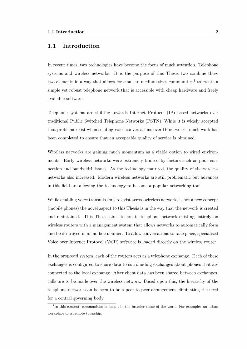
In recent times, two technologies have become the focus of much attention. Telephone
systems and wireless networks. It is the purpose of this Thesis two combine these
two elements in a way that allows for small to medium sizes communities1 to create a
simple yet robust telephone network that is accessible with cheap hardware and freely
available software.
Telephone systems are shifting towards Internet Protocol (IP) based networks over
traditional Public Switched Telephone Networks (PSTN). While it is widely accepted
that problems exist when sending voice conversations over IP networks, much work has
been completed to ensure that an acceptable quality of service is obtained.
Wireless networks are gaining much momentum as a viable option to wired environ-
ments. Early wireless networks were extremely limited by factors such as poor con-
nection and bandwidth issues. As the technology matured, the quality of the wireless
networks also increased. Modern wireless networks are still problematic but advances
in this field are allowing the technology to become a popular networking tool.
While enabling voice transmissions to exist across wireless networks is not a new concept
(mobile phones) the novel aspect to this Thesis is in the way that the network is created
and maintained. This Thesis aims to create telephone network existing entirely on
wireless routers with a management system that allows networks to automatically form
and be destroyed in an ad hoc manner. To allow conversations to take place, specialised
Voice over Internet Protocol (VoIP) software is loaded directly on the wireless router.
In the proposed system, each of the routers acts as a telephone exchange. Each of these
exchanges is configured to share data to surrounding exchanges about phones that are
connected to the local exchange. After client data has been shared between exchanges,
calls are to be made over the wireless network. Based upon this, the hierarchy of the
telephone network can be seen to be a peer to peer arrangement eliminating the need
for a central governing body.
1In this context, communities is meant in the broader sense of the word. For example: an urban
workplace or a remote township.

1.1 Introduction 3
This Thesis enables a very simple telephone network to be created and maintained on
wireless broadband routers. It illustrates that the proposed system is both feasible and
practical using current technology in both hardware and software. Critical evaluation
of the quality and capacity of the telephone system over wireless networks is carried
out in this Thesis and will be further discussed.

1.2 Alternative Systems 4
1.2 Alternative Systems
Systems that are currently in use are based upon proven technologies that are well
established but are all limiting in some way. These limiting factors relate to secu-
rity, flexibility, management as well as installation and operating costs. Examples of
currently used alternatives include traditional telephone systems, hand-held radio de-
vices and Voice over Internet Protocol (VoIP) (both proprietary and freely available
solutions).
Traditional wired telephone systems are extremely widespread and effective solutions
that provide a satisfactory service. After many years and technological advances, the
traditional telephone system is very robust method for enabling users to converse over
great and small distances.
One of the problems of traditional telephone systems is way that they are installed and
managed. Adding extra telephones and is not a simple task and involves specialized
equipment and technical knowledge. This can be a costly exercise and may take some
time for a technician to complete.
Another consideration is the physical layout of the area that is to have a telephone
network. If the environment changes over time2, or is hard to access, installations may
not able to be completed.
The system being proposed in this Thesis is designed to operate over limited distances as
a stand alone network. Compared to traditional telephone networks, the area covered by
the network is very limited. It is envisioned that the concepts presented her will allow
multiple wireless telephone networks to be linked with low latency, high bandwidth
internet connections.
One of the greatest advantages of the proposed system is the ability for phones to be
added to the network with little networking or telephone system knowledge. Manage-
ment of the network is regulated automatically, removing the need for users to rely
on a third party to make alterations to the telephone network. This Thesis also aims
2Open cut mines are a good example of the changes mentioned
1.2 Alternative Systems 5
to allow users in remote and/or difficult to access areas to have a reliable and robust
telephone system.
Systems that are able to operate wirelessly, such as Citizen Band (CB) radio devices,
also allow the creation of a communications systems that are able to operate in difficult
areas. In addition to this, the systems are managed by the users and are free to use. The
disadvantages that are associated with these systems include privacy, limited channels
and range.
Typically CB radios have 40 channels that are available to carry audio, and each of these
channels are open to anyone to listen to. This raises serious privacy issues that make the
systems unsuitable for the broadcast of sensitive information. Another consideration is
that 40 channels are quickly consumed by small numbers of users.
Once the number of users exceeds the available channels, careful channel management
is needed and can become cumbersome. Range of the units is also a concern when using
hand-held devices, without repeater stations to retransmit signals the system becomes
limited.
The proposed system alleviates many of the problems discussed. Privacy is greatly
increased with eavesdroppers made to attack the telephone system rather than passively
listen in to broadcasts. Channel management is eliminated and replaced with telephone
extension management3 with more extensions added easily. Finally, the range of the
network is controlled by the number of wireless routers that are in range of each other.
VoIP networks are a new and rapidly growing technology, many variations exist and
all differ in some way. Many proprietary and freely available systems are available to
be used. Proprietary systems are among some of the best communication devices4 but
require users to have access to the internet.
Many of the freely available versions of VoIP systems provide much the same func-
tionality that is found in traditional systems and existing proprietary VoIP systems.
This thesis uses a freely available telephone networking program, Asterisk, which is
3the number of unique extensions is almost endless4The quality of Skype conversations often have a higher quality sound than traditional systems

1.2 Alternative Systems 6
one of the premier VoIP solutions available. This software is added to and modified to
create the system being discussed here. A novel approach is being applied to telephone
systems in this thesis and it is envisioned that the best elements of each the alternative
systems presented, is utilised while the lacking areas of each is overcome.
1.3 Need for System 7
1.3 Need for System
In many areas, whether they be remote sites or small areas in an urban environment,
there exists a real lack of low cost, easily installed and maintained telephone systems. It
is the aim of this project to provide a system that is suited to aforementioned situations.
It can be seen in real world applications that implementing telephone systems are costly
and difficult especially in challenging environments. Some examples include:
∙ Remote areas with little traditional network access.
∙ Offshore situations (Oil rigs, fleets).
∙ Temporary sites (Demountable offices).
In situations such as those listed above it can be imagined that a cheap and simple
wireless telephone network could be an essential element.
1.4 Benefits of System 8
1.4 Benefits of System
While the proposed system has obvious advantages over existing solutions including:
∙ Low cost of equipment.
∙ Ease of installation.
∙ Little maintenance of system.
∙ Ease of use (similar to traditional systems).
∙ Ability to form and maintain computer networks.
There are additional benefits to having such a system. These benefits are more to do
with the router and its’ abilities to transmit multiple types of data. As the network of
nodes behave in a similar manner to wired Local Area Networks (LAN) many services
are able to be distributed across the network. Some of the benefits include:
∙ Ability to distribute Internet access.
∙ Ability for the wireless nodes to perform multiple functions (data logging, con-
trolling).
∙ Ability for the telephone to interface with traditional systems (call outside lines).
All of the above abilities are able to be allowed across the wireless connections. These
functions are expected to be implemented when creating an actual system but are
outside the scope of this Thesis.
1.5 Work Conducted 9
1.5 Work Conducted
During the course of this project many obstacles had to be overcome in order to com-
plete a working system. One of the key problems associated with the project was
allowing each of the wireless nodes to be able to identify the telephone network servers
around it. This was a major part of this project and this is covered in great detail in
section 4.3.
Other, less intensive aspects that needed to be dealt with included:
∙ Determining the layout of the network and the devices in the network(Section 3.1).
∙ Installing the new firmware for the router(Section 4.1.1).
∙ Configuring the router to apply desired network configuration(Section 4.1.4).
∙ Installing/Configuring the telephone network software(Section 4.2).
∙ Testing the system suitably(Section 5.3).
At the conclusion of this process, a large discussion area is provided to determine the
effectiveness of the system and this can be seen in chapter 6.

1.6 Chapter Summary 10
1.6 Chapter Summary
This chapter outlines the proposed system, its’ need in the real world and gives a
brief glimpse of how the system will operate. Throughout the following chapters, the
elements discussed here will be explained in great detail and also their integration into
the system will be shown.
Chapter 2
Literature Review
This chapter sets out to give an understanding of some of the key concepts and com-
ponents that the system is built upon. Some of the underlying principles the pertain
to the project are outlined below and are discussed in much detail throughout this
chapter:
∙ Wireless Mesh Networks.
∙ Telephone Systems.
∙ Audio Codecs.
∙ Router Specific Firmware.
Each of the components listed above form the various sections of this chapter and are
the building blocks that the project is formed upon.
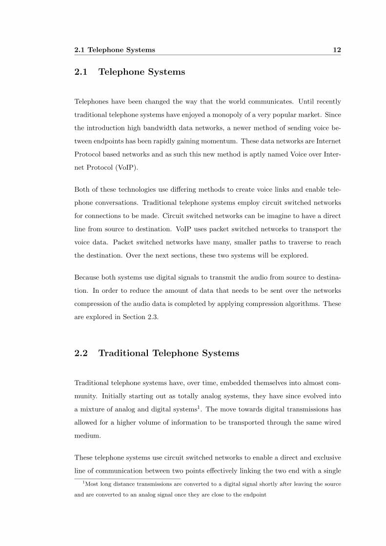
2.1 Telephone Systems 12
2.1 Telephone Systems
Telephones have been changed the way that the world communicates. Until recently
traditional telephone systems have enjoyed a monopoly of a very popular market. Since
the introduction high bandwidth data networks, a newer method of sending voice be-
tween endpoints has been rapidly gaining momentum. These data networks are Internet
Protocol based networks and as such this new method is aptly named Voice over Inter-
net Protocol (VoIP).
Both of these technologies use differing methods to create voice links and enable tele-
phone conversations. Traditional telephone systems employ circuit switched networks
for connections to be made. Circuit switched networks can be imagine to have a direct
line from source to destination. VoIP uses packet switched networks to transport the
voice data. Packet switched networks have many, smaller paths to traverse to reach
the destination. Over the next sections, these two systems will be explored.
Because both systems use digital signals to transmit the audio from source to destina-
tion. In order to reduce the amount of data that needs to be sent over the networks
compression of the audio data is completed by applying compression algorithms. These
are explored in Section 2.3.
2.2 Traditional Telephone Systems
Traditional telephone systems have, over time, embedded themselves into almost com-
munity. Initially starting out as totally analog systems, they have since evolved into
a mixture of analog and digital systems1. The move towards digital transmissions has
allowed for a higher volume of information to be transported through the same wired
medium.
These telephone systems use circuit switched networks to enable a direct and exclusive
line of communication between two points effectively linking the two end with a single
1Most long distance transmissions are converted to a digital signal shortly after leaving the source
and are converted to an analog signal once they are close to the endpoint
2.2 Traditional Telephone Systems 13
wire. This allows for uninterrupted communication with constant latency.
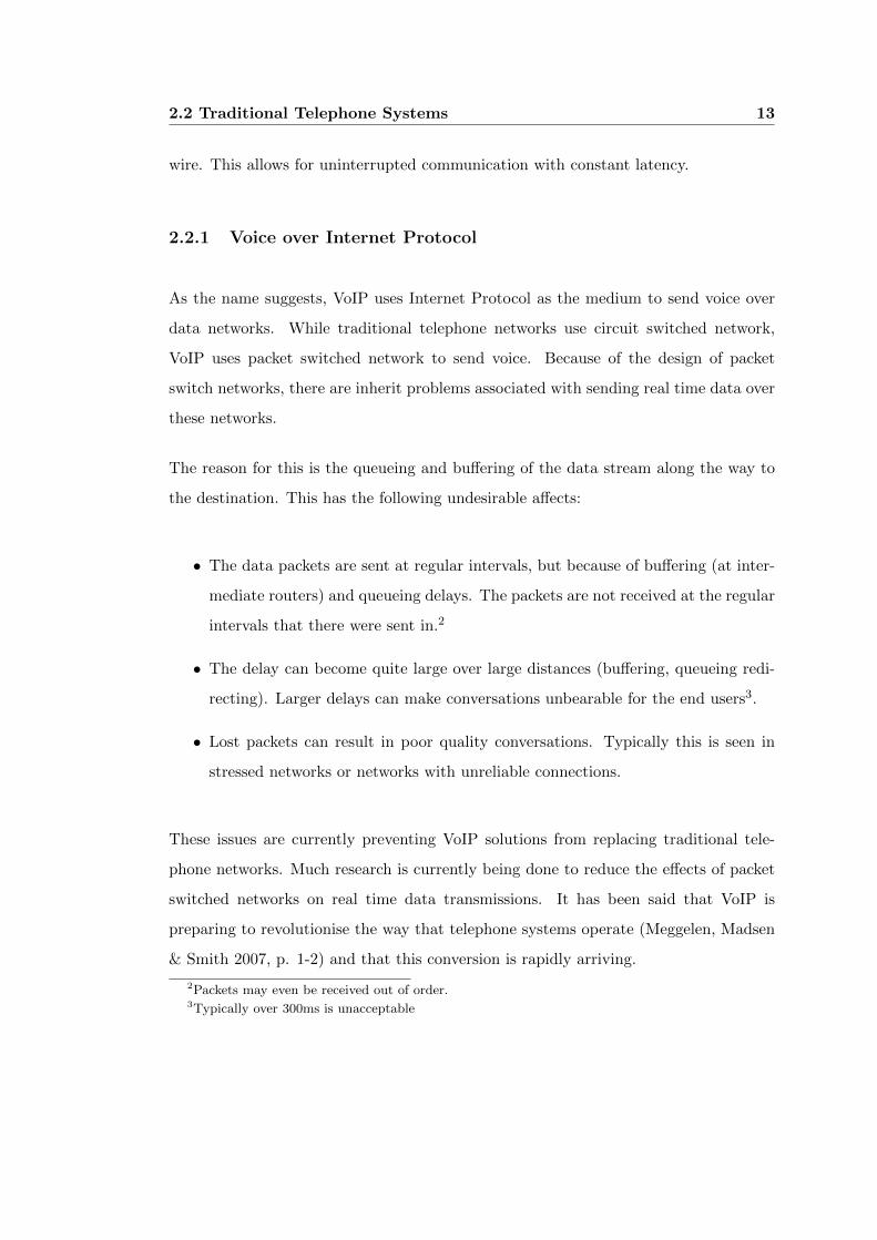
2.2.1 Voice over Internet Protocol
As the name suggests, VoIP uses Internet Protocol as the medium to send voice over
data networks. While traditional telephone networks use circuit switched network,
VoIP uses packet switched network to send voice. Because of the design of packet
switch networks, there are inherit problems associated with sending real time data over
these networks.
The reason for this is the queueing and buffering of the data stream along the way to
the destination. This has the following undesirable affects:
∙ The data packets are sent at regular intervals, but because of buffering (at inter-
mediate routers) and queueing delays. The packets are not received at the regular
intervals that there were sent in.2
∙ The delay can become quite large over large distances (buffering, queueing redi-
recting). Larger delays can make conversations unbearable for the end users3.
∙ Lost packets can result in poor quality conversations. Typically this is seen in
stressed networks or networks with unreliable connections.
These issues are currently preventing VoIP solutions from replacing traditional tele-
phone networks. Much research is currently being done to reduce the effects of packet
switched networks on real time data transmissions. It has been said that VoIP is
preparing to revolutionise the way that telephone systems operate (Meggelen, Madsen
& Smith 2007, p. 1-2) and that this conversion is rapidly arriving.
2Packets may even be received out of order.3Typically over 300ms is unacceptable
2.2 Traditional Telephone Systems 14
2.2.2 Providers os Systems
Traditional telephone systems are generally maintained and owned by one or two com-
panies. These companies own the infrastructure for the telephone network and as such
have alot of control over the pricing access to the services.
VoIP implementations on the other hand do not generally control and any infrastructure
but provide a means by which to enable telephone conversations to take place over data
networks. Many VoIP providers exist with some proprietary solutions such as SkypeTM
and other free distributions such as Asterisk.
2.3 Audio Codecs 15
2.3 Audio Codecs
Audio codecs (COder / DECoder) are used to encode analog signals that are within
the human sonic range (typically 12Hz to 20 000 Hz) into a digitized approximation of
the original signal. In a telephone system, analog signals are captured by a microphone
on the handset then converted to a digital signal. Once this digital signal is received
at the other end it is converted back to an analog signal and sent to a speaker so it
can be heard. This conversion takes place so that the information is able to be sent on
computer networks.
Typically, audio codecs are able to compress the digital signal in order to reduce the
amount of data that needs to be transmitted between endpoints. The amount of com-
pression that each codec is able to complete differs and as such the resulting quality of
the reconstructed signal varies also. The compression of audio for transmission across
a network is an important aspect to consider when designing a VoIP system. If the
compression algorithm is poor, the bandwidth required by one telephone conversation
may use most of the available bandwidth in the network. On the other hand, if the
compression is too great, the quality of the telephone conversion may be degraded to
a point where it is difficult to maintain a conversation.
There are many audio codecs available but only a handful that are supported by Aster-
isk. These codecs that are supported by Asterisk are very common audio codecs and
offer a great choice for the selection of a suitable audio codec for the project. Most
codecs that are integrated into equipment (mobile phones, IP telephones) are supported
by Asterisk and various quality tests will be conducted on the audio quality.
The choice of audio codec is an important aspect of the project as one of the limiting
factors of VoIP is the bandwidth available in the WMN. Although the G.711 is gener-
ally credited a higher quality reproduction of audio, an extensive range of tests were
conducted on various age groups and it was found that the G.729A codec gave a better
Mean Opinion Score (MOS) than the G.711 codec (4.02 versus 3.65 out of a possible
5) when voices were recorded and played back to the listeners (Light 2004).
For this reason, these two codecs are to be considered for the encoding for the telephone
2.3 Audio Codecs 16
network. By using these two codecs it is hoped that a suitable selection can be made
for anyone considering implementing the project being presented in this paper.
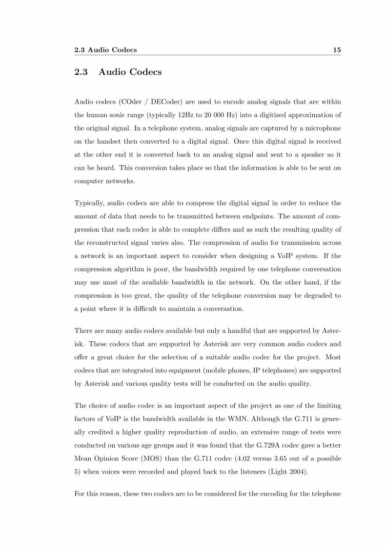
Table 2.1 shows the characteristics of the two codecs being considered for this project.
It should be noted that the bit rate of the G.711 is eight(8) times that of the G.729A
codec which further shows the importance of de-jitter, queueing delay and queueing
loss when selecting an audio codec.
Codec Creator Codec Bandwidth Frame Size Number of Frames
(Kilo Bits / Second) (milliseconds) per Second
G.711 ITU-T 64 20 50
G.729A ITU-T 8 20 50
Table 2.1: Showing Codec Characteristics
Another important point to note is that of the ability of sending faxes using the codecs.
While this is outside the scope of the project it may be implemented in a system based
on this project and as such it should be noted that the G.711 codec can handle fax
tones but G.729A will not. If a fax machine were to be connected to this system care
must be taken to ensure that the G.711 codec is used.
2.3.1 G.711
The G.711 audio codec was released in 1972 with the primary focus on encoding speech
for use in telephony applications. The actual process used to encode the analog voice
signal to a digital signal for transmission across a network is called Pulse Coded Modu-
lation (PCM). This technique uses bits to represent the input level of an analog signal
and then preforms an Analog to Digital Conversion (ADC) on that signal to get a
approximation of the original signal. This codec uses 8000 samples per second (8kHz)
with eight(8) bits representing each sample hence using a total of 64kbps.
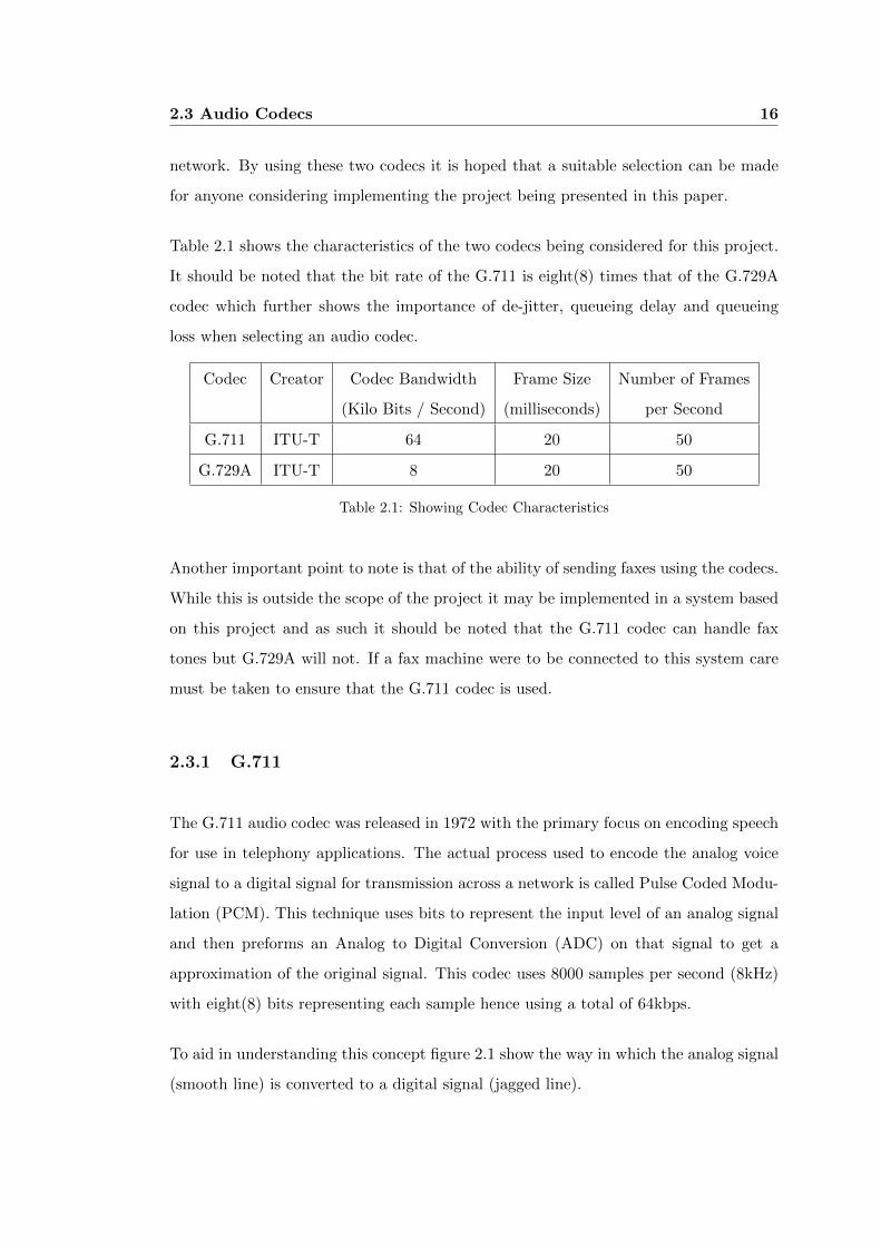
To aid in understanding this concept figure 2.1 show the way in which the analog signal
(smooth line) is converted to a digital signal (jagged line).
2.3 Audio Codecs 17
Figure 2.1: Pulse Coded Modulation
2.3.2 G.729A
The G.729 Audio codec uses a different encoding algorithm to the G.711 audio codec
and that is Conjugate-Structure Algebraic-Code-Excited Linear Prediction (CS-ACELP).
Code Excited Linear Prediction (CELP) works by using linear predictions on excita-
tions and was developed in 1985. This type of audio compression and the variations of
it are one of the most widely applied speech coding algorithms in use.
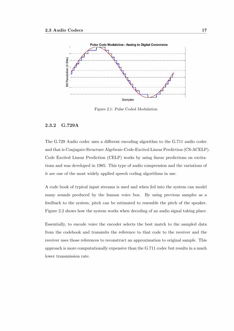
A code book of typical input streams is used and when fed into the system can model
many sounds produced by the human voice box. By using previous samples as a
feedback to the system, pitch can be estimated to resemble the pitch of the speaker.
Figure 2.2 shows how the system works when decoding of an audio signal taking place.
Essentially, to encode voice the encoder selects the best match to the sampled data
from the codebook and transmits the reference to that code to the receiver and the
receiver uses those references to reconstruct an approximation to original sample. This
approach is more computationally expensive than the G.711 codec but results in a much
lower transmission rate.
2.4 Wireless Networks 18
Figure 2.2: Code Excited Linear Prediction
2.4 Wireless Networks
Wireless communication as we know it today, had their beginnings when Guglielmo
Marconi transmitted a radio frequency wireless transmission over a distance of 18 miles
in 1895(Nicopolitidis, Obaidat, Papadimitriou & Pomportsis 2003, page 2). The first
wireless data network was created in 1971, when the university of Hawaii shared data
across islands. This network was named ALOHANET(Nicopolitidis et al. 2003, pages
7-8). Wireless data networks have evolved since their introduction and currently the
IEEE 802.11 networks are the most popular standards for the wireless data networking.
2.4.1 Wireless Data Networks
Currently, the most common wireless standard is 802.11 introduced by the Institute of
Electrical and Electronics Engineers (IEEE). Since defining the standard in 1997, the
standard has been amended with with popular variants being 802.11a (1999) 802.11b
(1999) and the 802.11g (2003)(Gast 2005, page 10). These standards have penetrated
many areas and are still growing at a rapid rate. The main reason for the rapid
expansion of wireless networks is primarily the cheap cost to users. Another reason for
the success of the technology is the degree of freedom experienced. With most areas
covered by wireless access, the ability to access network resources quickly and quickly
2.4 Wireless Networks 19
has proved a popular system.
Most wireless networks consist of an access point and clients. These clients all commu-
nicate with the access point and the services are distributed out of the access point.
These are labeled Wireless Local Area Networks4 (WLAN) and are an extremely pop-
ular type of wireless network. Another popular wireless network is the wireless ad hoc
network where temporary networks are formed when wireless devices come into range
of one another. These sort of networks are generally formed with low power devices
such as mobile phones and netbooks but can employ higher powered devices.
Recently, a new concept has been brought forward which is set to change the way that
public networks operate. This network architecture is named Wireless Mesh Networks.
4Because of the similar architecture to wired Local Area Networks
2.5 Wireless Mesh Networks 20
2.5 Wireless Mesh Networks
“Wireless Mesh Networks (WMNs) are dynamically self-organized and self configured,
with the nodes in the network automatically establishing an ad hoc network and main-
taining the mesh connectivity” (Akyildiz & Wang 2005, p. S23).
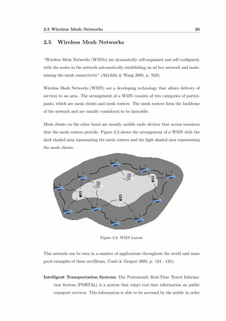
Wireless Mesh Networks (WMN) are a developing technology that allows delivery of
services to an area. The arrangement of a WMN consists of two categories of partici-
pants, which are mesh clients and mesh routers. The mesh routers form the backbone
of the network and are usually considered to be immobile.
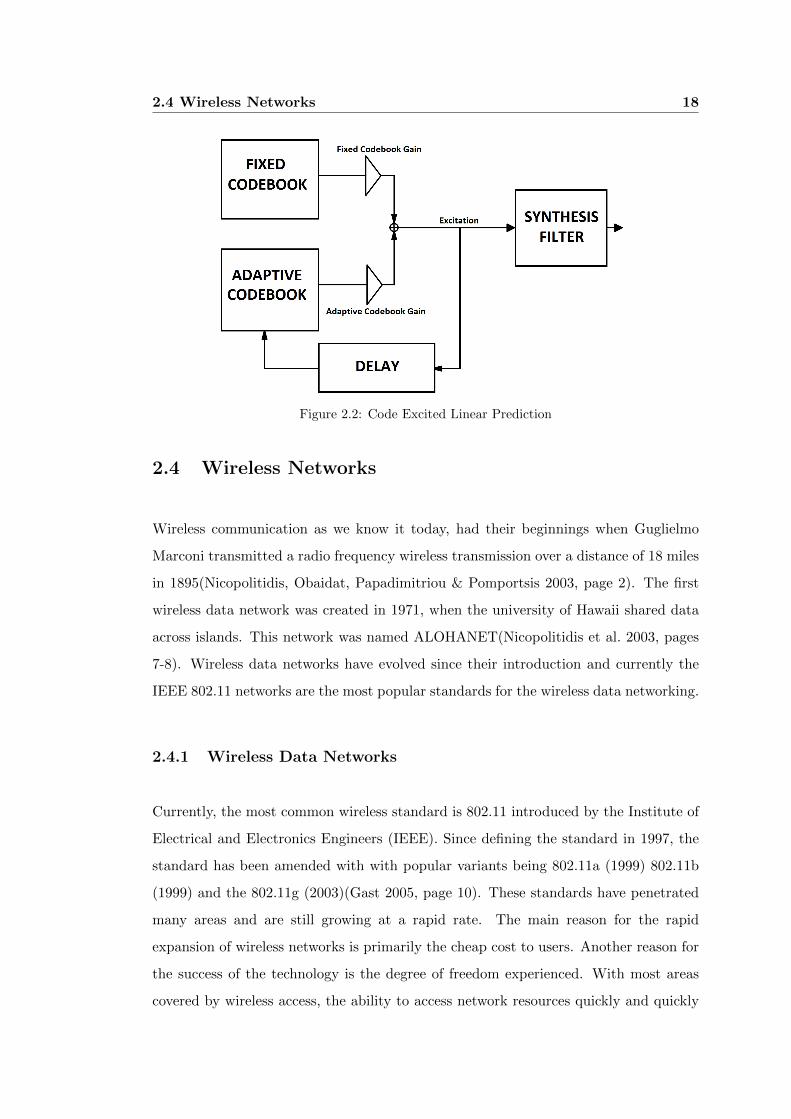
Mesh clients on the other hand are usually mobile radio devices that access resources
that the mesh routers provide. Figure 2.3 shows the arrangement of a WMN with the
dark shaded area representing the mesh routers and the light shaded area representing
the mesh clients.
Figure 2.3: WMN Layout
This network can be seen in a number of applications throughout the world and some
good examples of these are(Bruno, Conti & Gregori 2005, p. 124 - 125):
Intelligent Transportation Systems The Portsmouth Real-Time Travel Informa-
tion System (PORTAL) is a system that relays real time information on public
transport services. This information is able to be accessed by the public in order
2.5 Wireless Mesh Networks 21
to better organise their travel around the city.
Public Safety The San Matteo Police Department in the San Francisco Bay Area
uses a mesh network to co-ordinate the officers around the area in real time. This
is in an effort to better organise assistance and co-operation between officers.
Public Internet Access Cerritos, California has an Internet Service Provider (ISP)
that provides Internet access to paying customers using a WMN that is installed
throughout the city.
WMN are described as communications networks that consist of radio nodes that form
a network in an ad hoc manner. WMN have become the focus of many researchers in
the past 10 - 15 years and much advancement has been made in this time. Although
there have been vast improvements to the bandwidth and quality of signals, many areas
such as packet routing exist where more research is necessary.
WMN are maturing quickly and with the price of hardware that is able to operate
within this area, many projects and consumer products are being created that are
taking advantage of this technology. One of the major aspects of this project is to
correctly configure and maintain a WMN that is capable of more than just routing
data between clients of the WMN but to provide a reliable and robust service that will
run in parallel with data routing.
2.5.1 Mesh Routers
Mesh routers provide a backbone for the WMN and as such, enable the distribution
for data routing and provision of resources. Common resources provided by WMN are
Internet access, Intranet access, file transfers and phones systems. Mesh routers usually
have more resources available to them as compared to mesh clients.
2.5.2 Mesh Clients
Mesh clients can be any radio device that accesses the WMN and uses the resources
provided by the WMN. These devices can range from mobile phones, PDAs (Personal
2.5 Wireless Mesh Networks 22
Digital Assistant) and laptops or netbooks. In order to connect to the WMN these
devices have to operate in the same radio frequency and be able to communicate with
the mesh routers.
2.6 Wireless Mesh Network Routing Protocol 23
2.6 Wireless Mesh Network Routing Protocol
Routing protocols are responsible for the delivery of data across a network. In a wired
environment (for example the Internet) this task is usually fairly straight forward as the
routers are immobile and reachable. Once a route has been found in a wired network it
is extremely unlikely to change. In environments where the topology changes from time
to time (mobile wireless network) the routing protocol needs to be able to determine
new paths to send the data along.
The design of wireless routing protocols has become a very active field of study for many
researchers and this can be seen by the amount of proposals being published over the
last 10 years. Thousands of designs have been designed, simulated and implemented in
this field, each with a specific application catered for. Each of these proposed wireless
routing protocols can be placed into three very broad categories, and they are: Reactive,
Proactive and Hybrids (mixture of reactive and proactive).
The reason for the vast amount of routing protocols for wireless networks is due to the
varying conditions of applications for wireless networks. Some of the aspects that are
used to determine the most suited routing protocol can be seen below:
∙ The expected mobility of the wireless routers.
∙ The number of wireless routers that are part of the network.
∙ The type of data being sent across the network.
∙ The physical layout of the network.
Depending on the situation a certain type of routing protocol should be implemented.
in the next three sections each of the categories will be looked at and an example of an
available routing protocol will be discussed.
2.6 Wireless Mesh Network Routing Protocol 24
2.6.1 Reactive
Reactive routing protocols are named as such due to the way that they react to requests.
When a request is made to send data to a certain destination, the routing protocol
send requests to surrounding nodes on the network. This messages that are sent to
surrounding nodes contain information pertaining to the requested destination, these
broadcasts are passed on until the destination is reached. Once the destination receives
the request the information is passed back along the path it was sent along back to the
original sender. In most applications, multiple paths are received and then a suitable
(usually shortest distance) path is selected and the data is sent along that path.
There are two main disadvantages to using a reactive routing protocol, and they can
be seen below:
∙ The process of determining the routes to various nodes on the network can cause
the network to become overwhelmed with path request packets. While one node
would be unlikely to cause this, when multiple nodes are determining routes across
the network it could be seen.
∙ There is a latency between attempting to send data and the data actually being
sent. This time is due to the time required to determine a path to the destination.
Reactive routing protocols are particularly beneficial in wireless networks that are
highly mobile in nature. One of the most common reactive routing protocols is Ad
hoc On-demand Distance Vector routing protocol(AODV) (Perkins & Royer 1999).
2.6.2 Proactive
Proactive routing protocols determine the path to all nodes in the network (in a similar
way to reactive routing protocols) but keep a table of all the paths to the nodes in a
table. This table is stored locally and when a request is made to send data to a specific
node, the node is looked up in the table and the path found there is used.
2.6 Wireless Mesh Network Routing Protocol 25
By using this method, data is quickly sent on the network. There are two major
disadvantages to using this method and they are:
∙ The size of the tables (that are stored locally) grow with every node on the
network. When many nodes are available in the network these tables can become
very large and may cause problems associated with available memory.
∙ When a node is broken (powered down or moves out of range) this type of routing
protocol may not recognise this fault before sending information along that path.
This would lead to data loss or errors on the network.
Proactive routing protocols are seen to perform better in environments that have lit-
tle to no mobility of nodes and that has nodes that are very reliable. One of the
most common reactive routing protocols is Optimized Linked State Routing proto-
col(OLSR) (Clausen & Jacquet 2003).
2.6.3 Hybrid
Hybrid routing protocols attempt to use the best parts of both the reactive and proac-
tive routing protocols whilst trying to avoid the disadvantages of both. One of the most
common hybrid routing protocols is Hazy Sighted Link State routing protocol(HSLS).
HSLS was developed by BBN technologies (BBN Technologies website 2009) in 2001
and revised in 2003 (Santivanez & Ramanathan 2003). HSLS keeps a table similar to
the one used in proactive routing protocols but also uses the reactive local updates
whenever a link is lost within two(2) hops of the node.
The disadvantages of this type of routing protocol are:
∙ Nodes receive updates from nodes that are further away less frequently and due
to this may not have an up-to-date view of the network. These less frequent
updates on distant nodes serve to reduce network bandwidth.
∙ Security mechanisms that are in-place may fail if key infrastructures are not in
2.6 Wireless Mesh Network Routing Protocol 26
reach of each other. However this is only likely in poorly designed (physical
location) networks.
Hybrid routing protocols perform well in environments that are somewhat in-between
those environments that reactive and proactive routing protocols are most suited to.
2.7 Security Issues 27
2.7 Security Issues
The implementation of security in data networks is an essential element that attempts
to prevent attacks upon equipment and data within the network. Many security mea-
sures are available for networks and these include firewalls, anti-virus protection and
controlling access to certain areas of networks.
Over the next sections, security in regards to wireless networks and Asterisk are eval-
uated.
2.7.1 Wireless Security
With the increasing amount of wireless networks, data security has become harder to
defend against. Much research has been done on this topic and security measures such
as WPA and WEP have been developed specifically aimed an wireless networks. The
devices provide some protection against malicious attackers and should be enabled in
the proposed system. This is especially true if sensitive material will be available on
the network.
Wireless security is outside the scope of this Thesis and will not be implemented.
2.7.2 Asterisk Security
Security within Asterisk is treated very seriously, many features have been added to
the VoIP system due to malicious attacks. One of the key problems is the ability for
an attacker to use the connections available on a system tom make calls through the
Asterisk server. Although the proposed system is not interfaced with an outside line,
future implementations of this system may.
Eavesdropping on a conversation is a real concern for this Thesis. With enough knowl-
edge and access to the wireless network, an attacker could force voice traffic to be
routed through their connection (or recorded) and allow the two way conversation to
be listened to.

2.7 Security Issues 28
Before employing this project in a real world situation, security would need to be
implemented to guard against such attacks. As this Thesis is not being deployed for
public use, this issue will not be further developed upon in the course of this Thesis.
2.8 Hardware 29
2.8 Hardware
There were two main pieces of hardware used when creating and testing the system
being proposed in this Thesis. The wireless routers that are used to perform the main
functions of the system and the IP phones. Although the IP phone is not an essential
part of the system (a software based phone could be used) it is included to give a full
picture of the system.
Over the following two sections, both the wireless router and the IP phone will be
discussed and the specifications and capabilities of each component given.
2.8.1 LinkSys WRT54GL Wireless Router
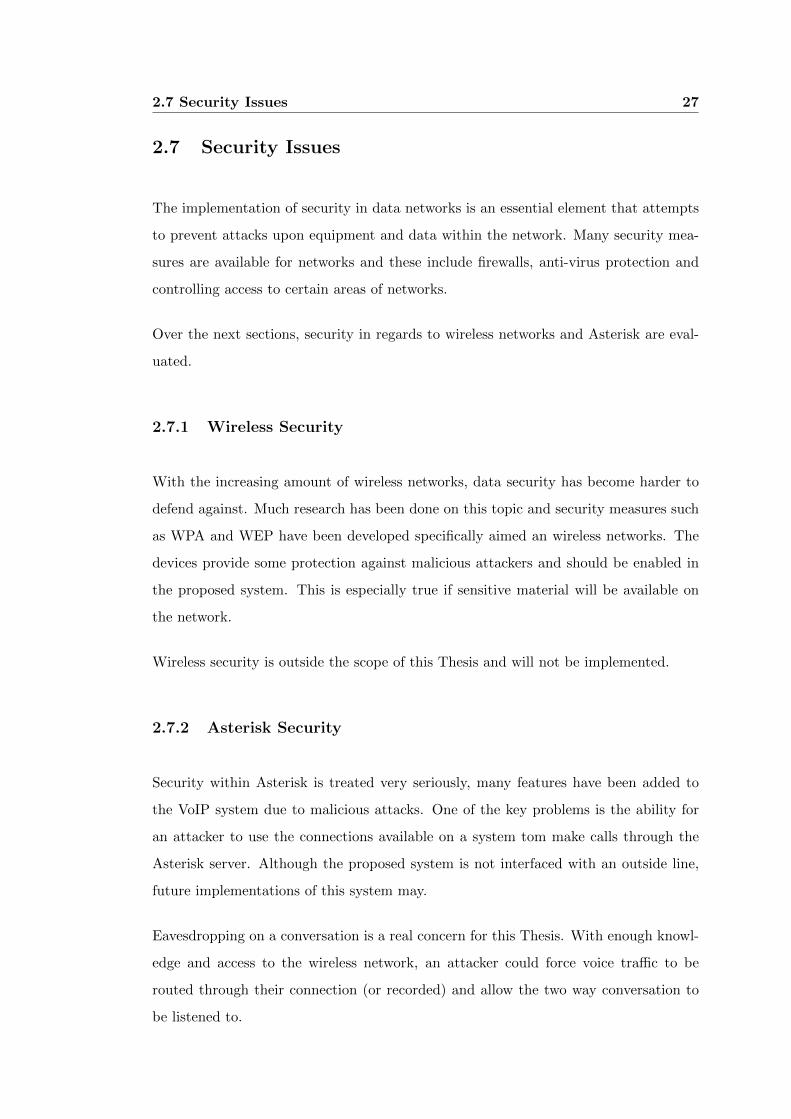
Figure 2.4: LinkSys WRT54GL
The WRT54G series of wireless router have been a popular line for Linksys mainly due
to the versatility of the units. In particular, the WRT54GL wireless router has been
popular and since its’ introduction in 2005. Two versions exist of the WRT54GL and
they are 1.0 and 1.1 (See table 2.2). The main difference between the two is that in
version 1.0, the maximum size of the firmware image that could be uploaded using the
preloaded firmware was 3MB. Later changed to 4MB when version 1.1 was released.
The WRT54GL supports the use of two wireless transmission standards and they are
IEEE 802.11b and IEEE 802.11g. The characteristics for these two standards can be
2.8 Hardware 30
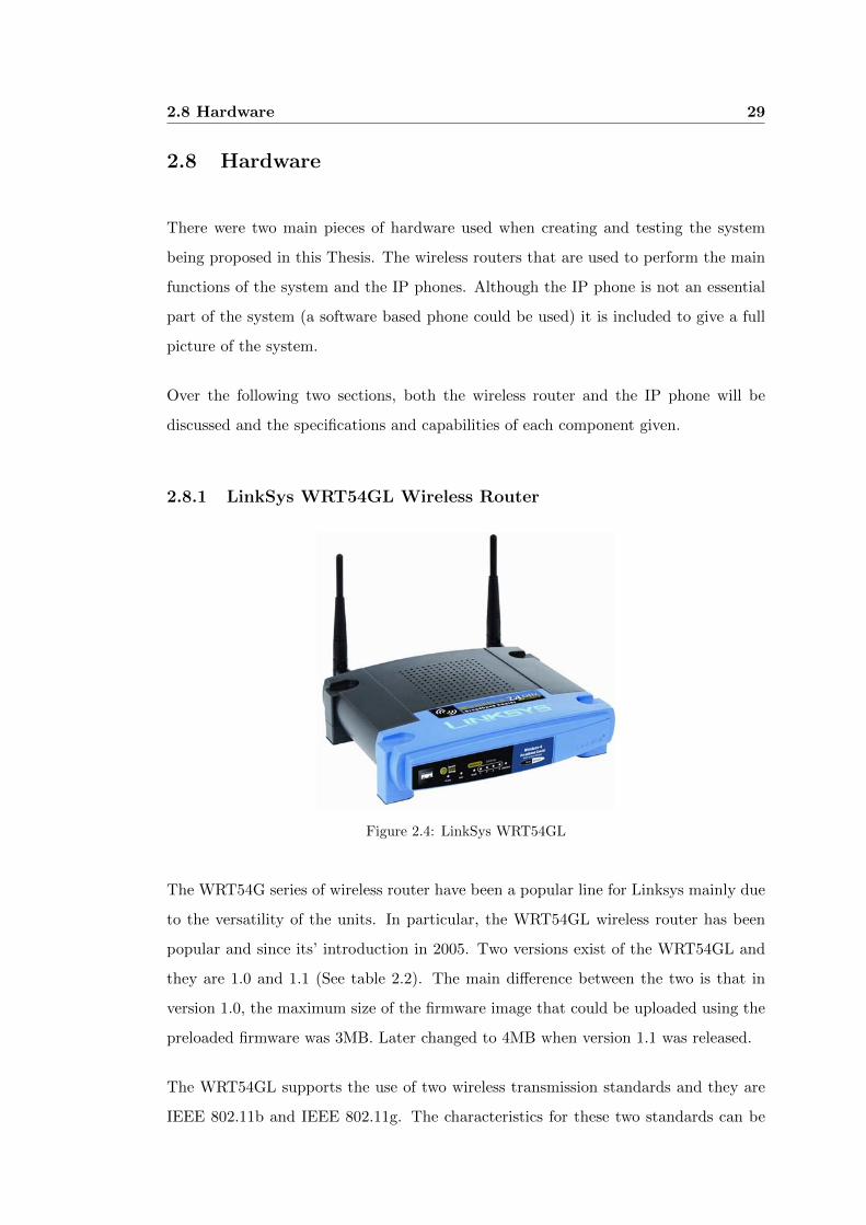
Version Processor Speed RAM Flash memory Release Date
(in MHz) (in MB) (in MB)
WRT54GL 1.0 200 16 4 2005
WRT54GL 1.1 200 16 4 2008
Table 2.2: Hardware specifications for the WRT54GL router
seen in table 2.3.
Protocol Release Frequency Typical throughput Max net bitrate
Date (GHz) (Mbit/s) (Mbit/s)
802.11b Sept 1999 2.4 4.3 11
802.11g June 2003 2.4 19 54
Table 2.3: Specifications for 802.11b and 802.11g
On of the key selling points of this router is the fact that LinkSys made the firmware
source publicly available. This has allowed community and commercial developers to
revise the firmware image for specific applications. These extensions to the firmware
allows the router to perform many extra functions on top of routing data wirelessly,
some of the popular applications for the router are listed below:
Creation Internet Hotspots Many people have successfully created an Internet hotspot
where wireless users are able to gain access to the internet through the wireless
router. Some providers use an active portal where users are forced to register (or
pay) before accessing the network (Hot Spot PA website 2009).
Controlling Robots There are some good examples that show the router controlling
motion and web cameras (ROBOSTUFF Website 2009). The router controls the
motors and servos as well as providing a way to access the robot wirelessly.
Adding Memory to the Router By modifying the hardware and adding an SD
memory card reader to a spare (unused) communication port on the router an
extra 2 gigabytes can be added to the memory of the router. Many application
for this extra memory can be implemented such as data logging or creating a
wireless file server (Adam Kowalewski website 2009).
2.8 Hardware 31
More information regarding alternative firmware images is available in section 3.2. A
complete listing of all of the technical information pertaining to the WRT54GL can be
found on the LinkSys website (WRT54GL Technical Information 2009).
2.8.2 LinkSys SPA901 IP Phone
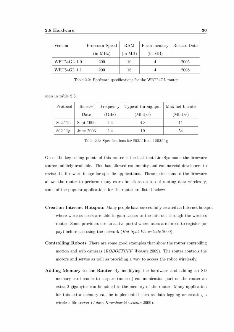
Figure 2.5: LinkSys SPA901
The SPA901 IP phone pictured in figure 2.5 is a robust unit that is able to communicate
with the system being developed. The key features can bee seen in table 2.4. The
phones’ settings are able to be modified in two ways. Firstly the configuration is able
to be modified by using a web interface. The alternate configuration is by using the
Interactive Voice Response (IVR) menu where commands are entered by key presses
on the keypad of the phone.
The phone has support for Session Initiation Protocol (SIP) which allows the phone
to register with a service provider. The SPA901 also supports the audio codecs G.711
and G.729 which are being used in this Thesis. Also the ability for the phone to be set
with either a static IP address or use a Dynamic Host Configuration Protocol (DHCP)
client to lease an IP address is supported by the phone. In this paper the DHCP client
will be running on all phones connected to the routers and therefore is a requirement
that this phone is able to complete.
More in-depth technical information for the SPA901 IP Phone can be found on the
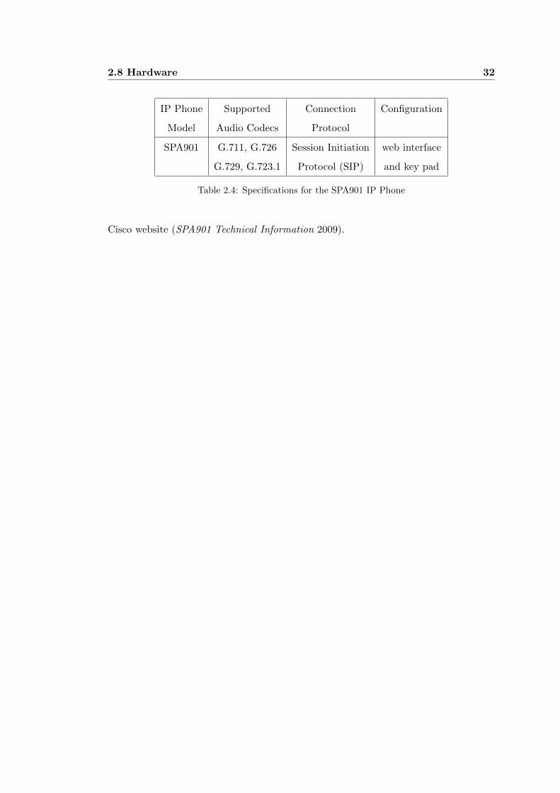
2.8 Hardware 32
IP Phone Supported Connection Configuration
Model Audio Codecs Protocol
SPA901 G.711, G.726 Session Initiation web interface
G.729, G.723.1 Protocol (SIP) and key pad
Table 2.4: Specifications for the SPA901 IP Phone
Cisco website (SPA901 Technical Information 2009).
2.9 Chapter Summary 33
2.9 Chapter Summary
Throughout this chapter an attempt is made for the reader to gain an understanding of
the various aspects of the project. It is these fundamental components that the project
is built upon and as such these concepts are needed to be understood in order to gain
an understanding into how the proposed system operates.
For the remainder of this document, these concepts will be integrated into the project
and will combine to allow various aspects of the system. The underlying principles
discussed in this chapter form the basis for which the rest of the project is built upon.
The results found during the process of researching this project, and shown in this
chapter, will be compared to actual results found in section 6.2.
Chapter 3
Design of Proposed System
This chapter covers the decisions and assumptions made about the proposed system
in regard to the network, the devices in the network and how they combine to offer a
robust telephone system. The key components of the system include:
∙ The wireless router.
∙ The IP phone.
∙ The firmware for the wireless router.
∙ The VoIP software (Asterisk).
∙ The various software portions that are responsible for the maintenance of the
system.
∙ The purpose designed programs that allow the automated configuration of the
telephone network.
Each Section of this chapter aims to give a brief insight into the operation of the various
aspects of the system but also defines how that aspect integrates into the system as a
whole.
3.1 Design Philosophy 35
3.1 Design Philosophy
One of the most fundamental aspects of this project is to first develop an idea of
how the system will operate. This process required many considerations about the
possible ramifications of the decisions made about seemingly straight forward aspects
of the system. Of particular interest, the following aspects were first looked at before
attempting any implementation:
∙ The expected mobility of the mesh routers.
∙ The portability of the IP phones and the ability to log onto a phone.
∙ Automatically connecting Asterisk servers.
∙ How the wired and wireless interfaces of the router would be handled.
∙ How the audio data is routed.
After deciding on how the system would operate, each of the key aspects of the system
was looked at to determine the feasibility of the implementation. Over the following
sections, these aspects will be discussed from a design perspective. Chapter 4 will
discuss the implementation of these concepts.
3.1.1 Mobility and Reliability of Mesh Routers
The mobility of the mesh routers goes towards the overall design of the system and the
selection of aspects such as the routing protocols used in the system. It is envisioned
that the mesh routers will mostly remain immobile in the practical application of the
system. The main reasoning for this is listed below:
∙ In order for a specific area of coverage for the WMN, the mesh routers (backbone)
are needed to remain in a set place.
∙ Most phones will remain fixed in place (inside a residence or office) and these
areas should remain relatively immobile.
3.1 Design Philosophy 36
∙ Most (if not all) routers will need to be plugged into a power source which limits
the mobility of the units somewhat. The support for mobile devices to interact
with the system.
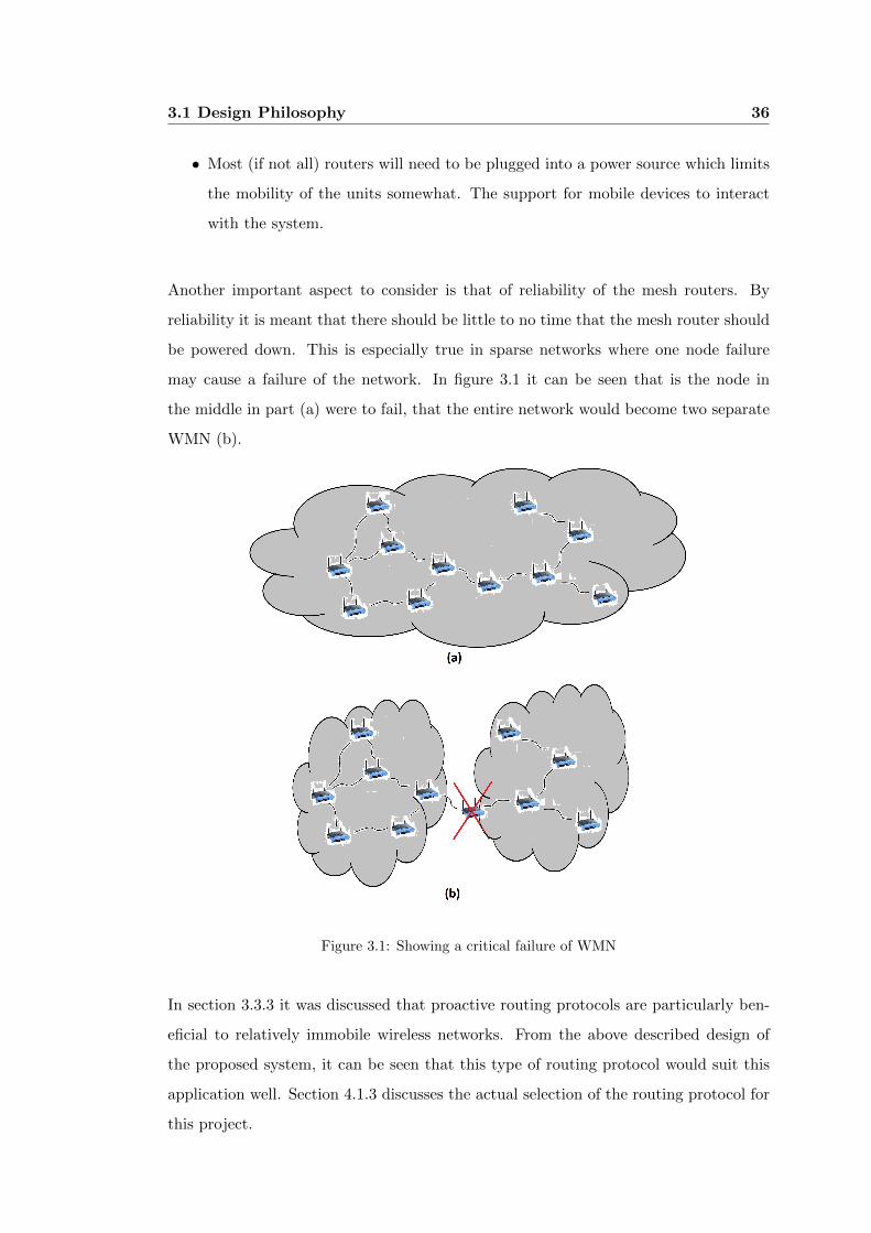
Another important aspect to consider is that of reliability of the mesh routers. By
reliability it is meant that there should be little to no time that the mesh router should
be powered down. This is especially true in sparse networks where one node failure
may cause a failure of the network. In figure 3.1 it can be seen that is the node in
the middle in part (a) were to fail, that the entire network would become two separate
WMN (b).
Figure 3.1: Showing a critical failure of WMN
In section 3.3.3 it was discussed that proactive routing protocols are particularly ben-
eficial to relatively immobile wireless networks. From the above described design of
the proposed system, it can be seen that this type of routing protocol would suit this
application well. Section 4.1.3 discusses the actual selection of the routing protocol for
this project.
3.1 Design Philosophy 37
3.1.2 Portability of IP Phones
The ability to move phones between mesh routers (Asterisk servers) is an attractive
idea for two reasons. Firstly, from time to time users may switch areas or sites and
would still like to have calls routed to their phone regardless of their physical location.
Secondly, when creating a telephone network, the ability to plug in a phone and have it
automatically configure itself with a mesh router would save a lot of time in the setup
of the telephone network.
The ability for the user to move within the telephone network and still be able to have
a phone within a close proximity can be completed in two ways. Firstly as described
above, the phone can be physically taken with the user and plugged into a closer mesh
router. Secondly, if the network has additional phones the user could log on to the
phone (change the extension of the phone to be the users’ extension). This ability to
log on may be more commonly used as the physical removal and transport of the phone
is cumbersome.
The ability for the phone to be moved to a different location and automatically re-join
the telephone network has been implemented into the system by running a Dynamic
Host Configuration Protocol (DHCP) server on the wired ports of the mesh router. In
this way, when an IP phone is plugged into a router, it leases an IP address off the router
and uses the default gateway (obtained as part of the DHCP server) to register with
the Session Initiation Protocol (SIP) server that is running concurrently with Asterisk
on the router (see section 4.1.4).
Once the SIP session has been configured and the Asterisk server is aware of the phone
(see section 4.3) calls can be made and received by the phone.
Another major aspect to consider is how the IP phones will be allowed to move around
the network. One potential solution to this is to have the IP phone always register with
the same Asterisk server regardless of where it is on the network while another is to
have it register with the Asterisk server that it is connected to.
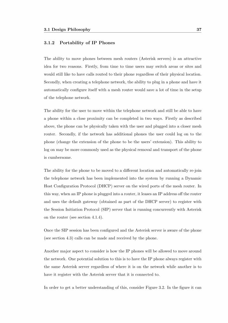
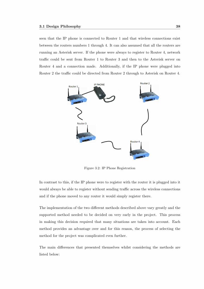
In order to get a better understanding of this, consider Figure 3.2. In the figure it can
3.1 Design Philosophy 38
seen that the IP phone is connected to Router 1 and that wireless connections exist
between the routers numbers 1 through 4. It can also assumed that all the routers are
running an Asterisk server. If the phone were always to register to Router 4, network
traffic could be sent from Router 1 to Router 3 and then to the Asterisk server on
Router 4 and a connection made. Additionally, if the IP phone were plugged into
Router 2 the traffic could be directed from Router 2 through to Asterisk on Router 4.
Figure 3.2: IP Phone Registration
In contrast to this, if the IP phone were to register with the router it is plugged into it
would always be able to register without sending traffic across the wireless connections
and if the phone moved to any router it would simply register there.
The implementation of the two different methods described above vary greatly and the
supported method needed to be decided on very early in the project. This process
in making this decision required that many situations are taken into account. Each
method provides an advantage over and for this reason, the process of selecting the
method for the project was complicated even further.
The main differences that presented themselves whilst considering the methods are
listed below:
3.1 Design Philosophy 39
∙ Network traffic caused by each of the methods.
∙ The use of nodes that are not running the Asterisk software.
∙ The configuration of wired and wireless interfaces of the router.
The network traffic generated by the two methods may vary greatly depending on the
layout of the network and the devices that are operating in the WMN. There are two
types of telephone network participants that need to be considered and they are:
∙ Phones that connect to the wireless interface of the WMN.
∙ Phones that are plugged into the wired interface of the mesh router.
Devices that connect to the mesh router via the wired interface can register directly
with the router that they are connected to or register with any other mesh router in
the network. The first method does not transmit data across the wireless network but
communicates with the router (more specifically the Asterisk server) directly. When
the phone registers with a remote server wireless traffic is sent and also the problem of
data backtracking can come into effect (see figure 3.3). As this project has the wired
and wireless interfaces separated there is also problems faced with NAT and firewalls
when attempting to send data to a device that is behind these security devices (see
section 3.1.3). These issues affect the case where a phone is able to register to a remote
Asterisk server.
With these considerations in place, the decision to force the phone to register with
the mesh router it is plugged into will be implemented. It should be noted that this
does not stop a user from connecting to a remote Asterisk server but this would have to
configured manually using the phone settings. By implementing the system in this way,
the automated configuration of the Asterisk servers and phones can be implemented.
Devices that connect to the wireless interface of the router are able to move freely
throughout the WMN and as such may move to a position in the WMN that would
cause the audio to back track through the network in order to reach the destination (this
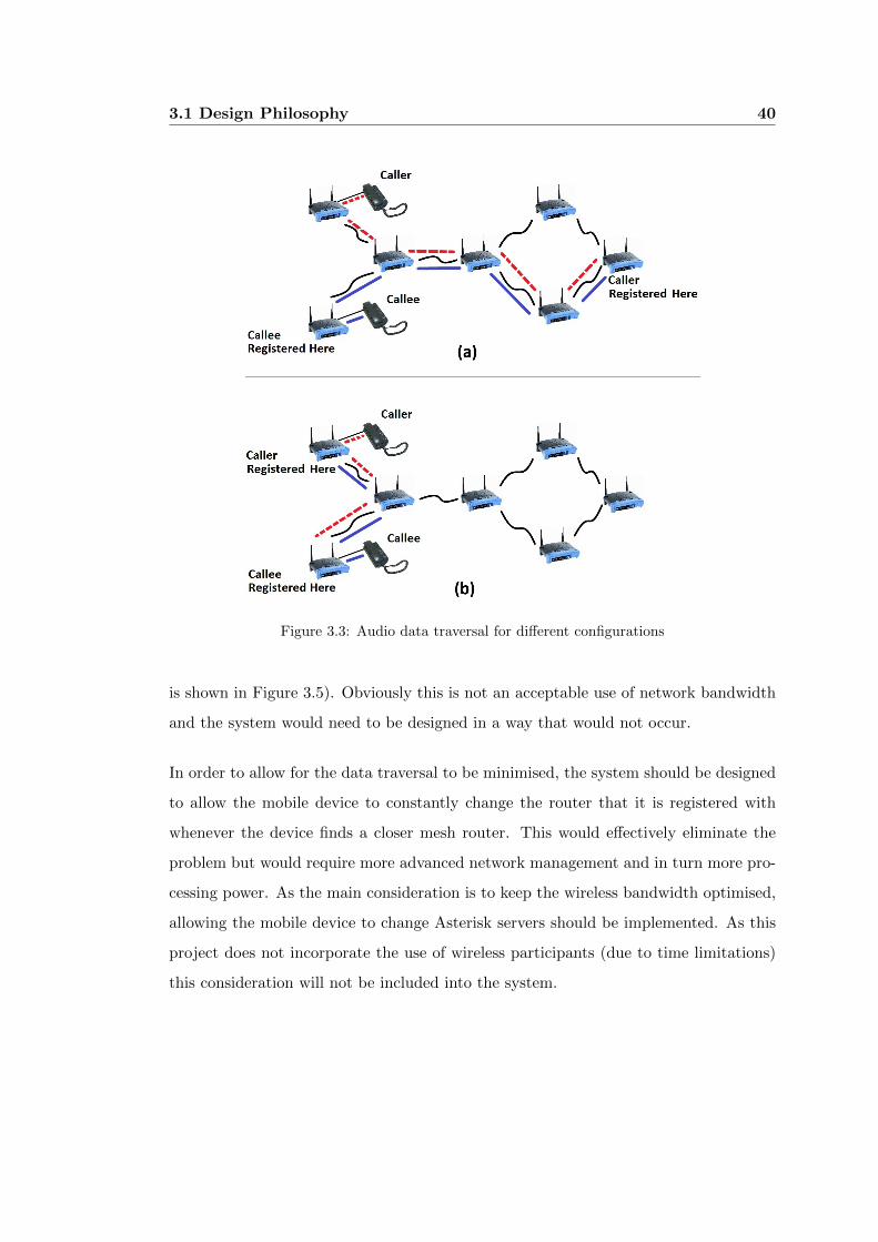
3.1 Design Philosophy 40
Figure 3.3: Audio data traversal for different configurations
is shown in Figure 3.5). Obviously this is not an acceptable use of network bandwidth
and the system would need to be designed in a way that would not occur.
In order to allow for the data traversal to be minimised, the system should be designed
to allow the mobile device to constantly change the router that it is registered with
whenever the device finds a closer mesh router. This would effectively eliminate the
problem but would require more advanced network management and in turn more pro-
cessing power. As the main consideration is to keep the wireless bandwidth optimised,
allowing the mobile device to change Asterisk servers should be implemented. As this
project does not incorporate the use of wireless participants (due to time limitations)
this consideration will not be included into the system.
3.1 Design Philosophy 41
3.1.3 Routing of Audio Data
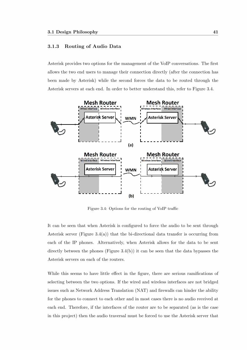
Asterisk provides two options for the management of the VoIP conversations. The first
allows the two end users to manage their connection directly (after the connection has
been made by Asterisk) while the second forces the data to be routed through the
Asterisk servers at each end. In order to better understand this, refer to Figure 3.4.
Figure 3.4: Options for the routing of VoIP traffic
It can be seen that when Asterisk is configured to force the audio to be sent through
Asterisk server (Figure 3.4(a)) that the bi-directional data transfer is occurring from
each of the IP phones. Alternatively, when Asterisk allows for the data to be sent
directly between the phones (Figure 3.4(b)) it can be seen that the data bypasses the
Asterisk servers on each of the routers.
While this seems to have little effect in the figure, there are serious ramifications of
selecting between the two options. If the wired and wireless interfaces are not bridged
issues such as Network Address Translation (NAT) and firewalls can hinder the ability
for the phones to connect to each other and in most cases there is no audio received at
each end. Therefore, if the interfaces of the router are to be separated (as is the case
in this project) then the audio traversal must be forced to use the Asterisk server that
3.1 Design Philosophy 42
resides on the router in order to bypass the NAT and firewall issues.
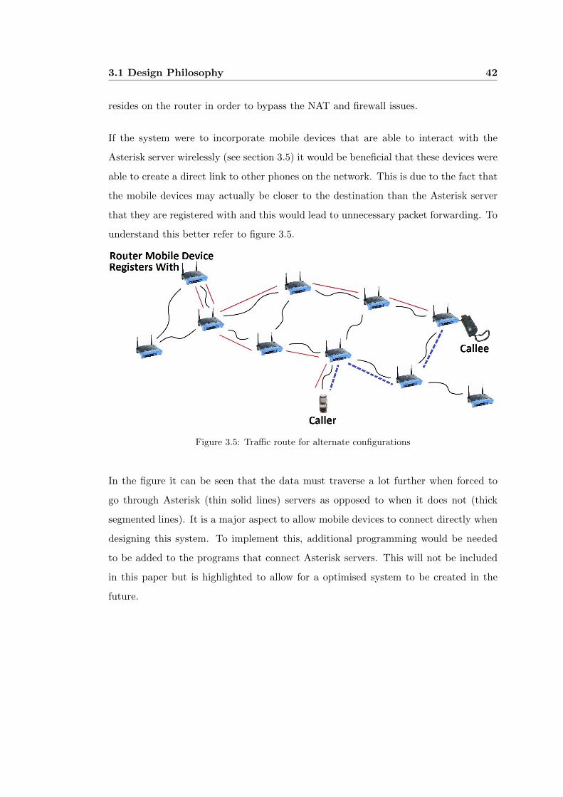
If the system were to incorporate mobile devices that are able to interact with the
Asterisk server wirelessly (see section 3.5) it would be beneficial that these devices were
able to create a direct link to other phones on the network. This is due to the fact that
the mobile devices may actually be closer to the destination than the Asterisk server
that they are registered with and this would lead to unnecessary packet forwarding. To
understand this better refer to figure 3.5.
Figure 3.5: Traffic route for alternate configurations
In the figure it can be seen that the data must traverse a lot further when forced to
go through Asterisk (thin solid lines) servers as opposed to when it does not (thick
segmented lines). It is a major aspect to allow mobile devices to connect directly when
designing this system. To implement this, additional programming would be needed
to be added to the programs that connect Asterisk servers. This will not be included
in this paper but is highlighted to allow for a optimised system to be created in the
future.
3.2 Firmware 43
3.2 Firmware
Institute of Electrical and Electronics Engineers (IEEE) Standard Glossary of Software
Engineering Terminology, Std 610.12-1990, defines firmware as:“The combination of a
hardware device and computer instructions and data that reside as read-only software
on that device”
In the case of this project, it refers to the software that is employed to control the
operation of the router and allow a user to modify and add programmability to the
device. It is essential that a Linux compatible firmware be installed to allow all software
such as Asterisk to run on the router. Many firmware distributions are available for
the WRT54GL and are discussed in the following sections.
3.2.1 Variations
There are multiple firmware images available for the Linksys WRT54GL wireless router.
These firmware images allow one to alter the operation of the router, more specifically,
they allow a small installation of Linux to become the operating system for the router.
The compatible distributions include, but are not limited to:
∙ Open-WRT (Official Open-WRT Website 2009)
∙ DD-WRT (Official DD-WRT Website 2009)
∙ Sveasoft (Official Sveasoft Website 2009)
∙ FreeWRT (Official Free-WRT Website 2009)
∙ Tomato (Official Tomato Website 2009)
These distributions can be loaded onto the router to replace the supplied firmware and
allow a lot of flexibility and configurability. Of the above listed firmwares, Open-WRT
and DD-WRT were the best choices for the specific application that is being proposed
in this paper. The reason for this is that the aforementioned distributions have a good
3.2 Firmware 44
developer base and are free to use. They both also have good community support for
troubleshooting and guides.
Open-WRT
Open-WRT was originally developed for the WRT54G series of routers as a replacement
for the stock firmware for the router. Open-WRT uses a Linux based firmware and has
allowed for the addition of many features that are not available with the stock firmware.
Some of the notable extensions are as follows:
∙ Static Dynamic Host Configuration Protocol (DHCP) server.
∙ Quality of Service (QoS) mechanisms for certain data types.
∙ Highly configurable firewall and other networking tools.
∙ Printer server and sharing abilities (with USB support).
The main reason for the success of the Open-WRT firmware is that it is a community
based project that is freely available for use. Many people have contributed to the
firmware with many other people revising the code constantly leading towards a very
stable base for the router to operate from.
DD-WRT
DD-WRT is also a Linux based firmware that is compatible for the WRT54GL wireless
router. As with Open-WRT, this firmware is a community based project and has
had much success in creating a very flexible firmware. All of the functionality that is
available from Open-WRT is included in the DD-WRT variation.
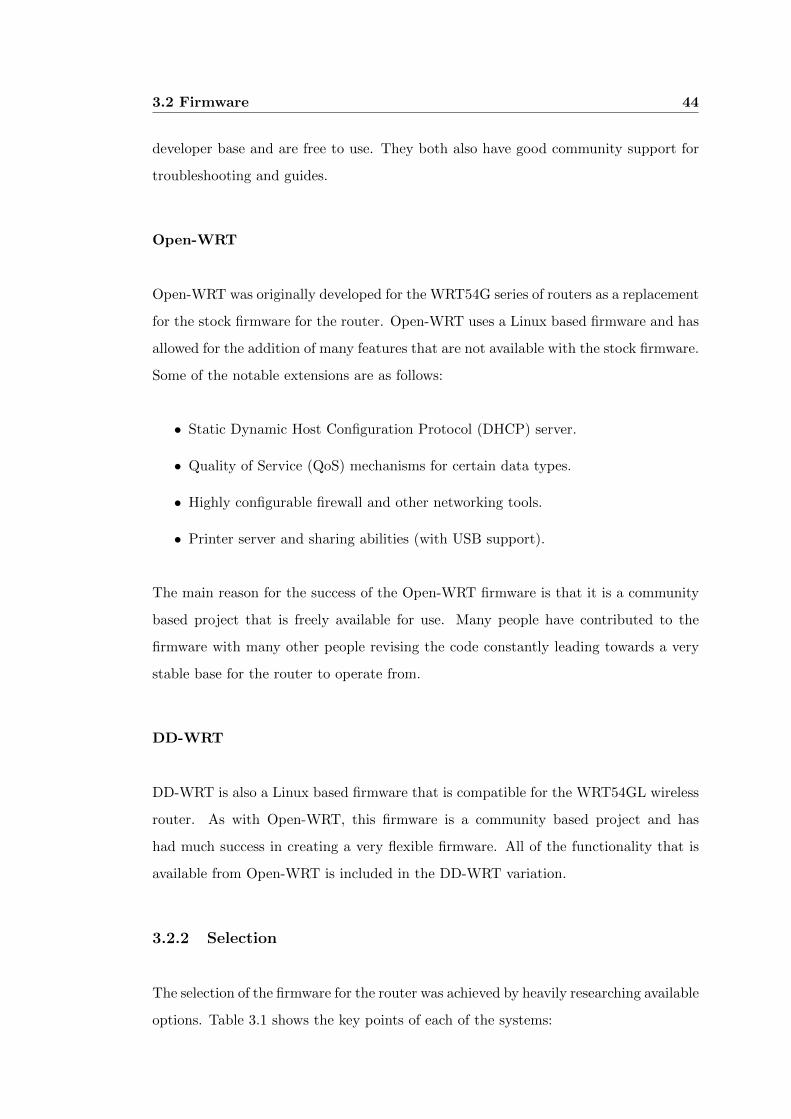
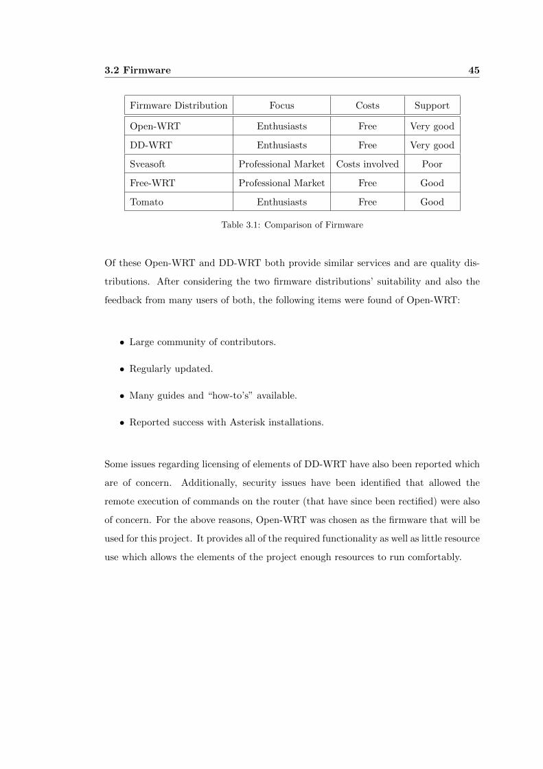
3.2.2 Selection
The selection of the firmware for the router was achieved by heavily researching available
options. Table 3.1 shows the key points of each of the systems:
3.2 Firmware 45
Firmware Distribution Focus Costs Support
Open-WRT Enthusiasts Free Very good
DD-WRT Enthusiasts Free Very good
Sveasoft Professional Market Costs involved Poor
Free-WRT Professional Market Free Good
Tomato Enthusiasts Free Good
Table 3.1: Comparison of Firmware
Of these Open-WRT and DD-WRT both provide similar services and are quality dis-
tributions. After considering the two firmware distributions’ suitability and also the
feedback from many users of both, the following items were found of Open-WRT:
∙ Large community of contributors.
∙ Regularly updated.
∙ Many guides and “how-to’s” available.
∙ Reported success with Asterisk installations.
Some issues regarding licensing of elements of DD-WRT have also been reported which
are of concern. Additionally, security issues have been identified that allowed the
remote execution of commands on the router (that have since been rectified) were also
of concern. For the above reasons, Open-WRT was chosen as the firmware that will be
used for this project. It provides all of the required functionality as well as little resource
use which allows the elements of the project enough resources to run comfortably.
3.3 Software 46
3.3 Software
Specialized software was needed to get a functioning telephone exchange running on the
wireless routers. This software has very specific jobs to perform within the system and
the design of the system relies heavily on these jobs being completed properly. These
software aspects of the system are:
∙ Asterisk is responsible for the call setup and maintenance of the network.
∙ The DHCP server exist to aid in the ability for devices to automatically join the
network.
∙ The OLSR routing protocol allows the wireless nodes to form a WMN.
∙ The Asterisk Client Information Sharing (ACIS) programs allow the telephone
network to automatically configure itself.
Also, configuration of the DHCP server was required to maintain connections between
the router and the IP phones that are plugged into the router. Service advertisement
methods were also coded and installed in order to implement automated configuration
of the Asterisk servers. The routing protocol that is responsible for the setup and
maintenance of the WMN is discussed in section 4.1.3.
3.3.1 Asterisk
Asterisk is an free and open source project that was created to provide an alternative to
conventional telephony systems. Since its’ inception in 1999 by Mark Spencer, Asterisk
has enjoyed the support of many members of the community. This community support
was available due to the fact that Asterisk has dual licenses including GNU General
Public License (GPL) and a proprietary software license to permit licensees to distribute
proprietary, unpublished system components. With the open source development, many
program bugs and additions were made to Asterisk enabling it to become a very robust
and efficient telephony system.
3.3 Software 47
Although Asterisk incorporates many features such as call conferencing, video calls,
mailbox creation and call forwarding, these features were not implemented in the set
up of the project. During the course of the project, only very basic settings for Asterisk
were used which allow call creation/termination of audio conversations. The main
reasons for the exclusion of the additional features included:
∙ Keeping the file system usage to a minimum.
∙ Reducing the complexity of the file maintenance.
∙ The capacity of a basic telephone system is able to be determined.
Asterisk is an free and open source project that was created to allow the creation of
telephone systems. At the time of writing, the supported Asterisk release is 1.0.10-1
for white Russian distribution of Open-WRT(Official Open-WRT Website 2009). This
version of Asterisk has multiple available versions for Open-WRT and of these, the
asterisk-mini 1.0.10-1 mipsel.ipk package was chosen for the reason that this distribu-
tion has the smallest install size while still providing all of the required functions that
are needed for the project.
Simple Asterisk setups are configured with the modification of two files (in most cases).
These two files control the phone connections (“sip.conf” or “iax.conf”) and what
steps are taken when a phone dials a number (“extensions.conf”). With very little
modification, a very basic VoIP telephone network is obtainable and calls are able to
be made.
3.3.2 DHCP Server
Open-WRT provides an open source DHCP (Dynamic Host Configuration Protocol)
server that can be run on the router to allow clients connected on the ethernet ports of
the router to lease an IP address from the router and connect to the SIP server (which
is part of Asterisk). This is available as a standard component in the firmware but also
is available as a package at http://downloads.openwrt.org/whiterussian/packages/ and
is called dnsmasq.
3.3 Software 48
This package is described as a lightweight, easy to configure DNS forwarder and DHCP
server. Although the DNS forwarder will not be considered for this project it is quite
useful in many networks. To enable the DCHP server to handle any IP phones that are
plugged into the router the configuration files for dnsmasq must be configured correctly.
This configuration will be shown in section 4.1.4.
3.3.3 OLSR Routing Protocol
Optimized Linked State Routing (OLSR) protocol is a proactive routing protocol (see
section 2.6) that allows for the interconnection of multiple nodes in a wired or wireless
network. OLSR attempts to maintain a constantly updated view of the network that is
a part of and does this by sending messages to its’ neighbours. a link state algorithm,
the information reagarding the node’ information (such as link quality) and location is
flooded throughout the network to give a good idea of the nodes in the network, OLSR
optimises the information that is transmitted to ensure that this information does not
cripple the network.
The variation of the OLSR routing protocol that is used in this project is called OLSRd
and was originally written by Andreas Tønnesen. Since the initial protocol was released
the code has been modified and the operation of the routing protocol optimised. Early
on there were issues that limited the number of nodes catered for to around a couple of
hundred but since the optimisation of code, the number of nodes that can be supported
is now within the thousands.
This routing protocol will be used in this project as it has been shown to perform very
efficiently in large networks and allows for the proposed system to remain connected at
a small cost to resources and bandwidth of the router and the network.
3.4 Asterisk Client Information Sharing (ACIS) 49
3.4 Asterisk Client Information Sharing (ACIS)
Because of the way that Asterisk is designed there is no way for it to automatically
discover and connect to other Asterisk servers. It should be noted that this is not a flaw
of Asterisk but has been carefully designed to operate this way. The reason for this is
that Asterisk is typically configured to connect to other services by an administrator
and is modified rarely (if at all) due to the static nature of wired telephones.
The ability for Asterisk to become aware of other Asterisk servers that are running
around them is a fundamental aspect to this project. A major success of the project
hinges on the way that this task is completed. There are two considerations for this
aspect and they are to ensure that the network is up-to-date and that the amount of
data that is being transmitted over the network is kept to a minimum.
In order to successfully implement a system that attempts to optimise these two princi-
ples, many scenarios were considered. The data contained in the messages sent between
Asterisk servers was kept to a minimum by using data contained in the headers for the
sent packets (seders’ IP address). Without carefully planning for when information is
needed to be sent and reducing the size of the packets this aspect of the project has
the ability to cripple the network with bloated information on the status of phones on
the network.
To enable the Asterisk servers to maintain a view of the network, client updates are
sent at regular intervals. The actual time interval used is very subjective and will vary
between applications. A very static phone network would not need to be updated as
often as a network where users are constantly being added and dropped.
The information contained in the data sent was reduced to strings containing the ex-
tensions1. In order to reduce the transmissions to this, the structure of the files “ex-
tensions.conf” and “sip.conf” were hard-coded into the programs that controlled the
transmissions. In this way simple loops were able to be used to rewrite the files in a
suitable format.
1Telephone identification numbers (Telephone Numbers)
3.4 Asterisk Client Information Sharing (ACIS) 50
It was also decided that when a phone disconnects that this information would not be
shared with all of the Asterisk servers in the network but rather that the details about
the phone (extension and location) are removed after not receiving an up date from
the phone after a certain time period. This also helped to reduce network traffic.
3.4.1 Transport Protocol for Messages
There are two protocols that transport data through IP networks. Each have advan-
tages over the other and to ensure that the proper method is chosen both were studied.
The two protocols are: User Datagram Protocol (UDP) and Transmission Control
Protocol (TCP).
Transport Protocol User Datagram Protocol Transmission Control Protocol
Guaranteed delivery No Yes
Bandwidth Used Least Most
Connection One to many / one to one One to one
Table 3.2: Comparison of Transport Protocols
From Table 3.2 it can be seen that TCP ensures that the sent data is received in tact and
in the correct order that is was sent in. UDP makes no guarantees about the delivery
of the packet at all. UDP packets are typically used in real time applications where
it is redundant to have the sender retransmit when a packet is lost. TCP connections
are used where data integrity takes precedence over timeliness. In order to keep the
Asterisk servers up-to-date, time is an important aspect but it is more important that
the information is received correctly.
It is also important that the most efficient method is used in a wireless environment.
TCP data integrity comes at a price of extra overhead. When little data is being sent
between servers, this overhead may actually incur more data than is being sent. In
the case of this project this is especially true, with most transmissions containing four
telephone numbers. This fact makes the UDP transport protocol a more attractive
option.
3.4 Asterisk Client Information Sharing (ACIS) 51
Finally, it can be seen that one to many connections can be made with UDP connections.
This is especially important in the proposed system as it is assumed that multiple
routers will be present in the WMN and being able to send one message to all other
routers will reduce the total bandwidth consumed for this aspect of the system.
For the reasons mentioned UDP broadcast messages are used in the implementation of
the Asterisk Client Information Sharing (ACIS) programs.
3.4.2 Detection of New Phones
From time to time it can be assumed that a new client will want to connect a new phone
into one of the Asterisk servers (Temporarily or permanently). This phone new phone
needs to be recognised and added to the two files “extensions.conf” and “sip.conf”. In
order to complete this, the Asterisk debug information needs to be regularly checked for
phones attempting to connect to the server2. When a phone is found, its’ information
is added to the system and Asterisk is told to reload the configuration files.
This does mean that until the phone attempts to reconnect, it will remain disconnected.
This could not be avoided in this project as developing an interface with the SIP server
would involve vast amounts of time. It may be beneficial to create an interface (or an
entirely new SIP server) that would allow for the automatic addition of phones.
2When a phone attempts to connect and is not in the “sip.conf” file, the connection is refused and
this information is saved to file.
3.5 Adding Support for Mobile Radio Devices 52
3.5 Adding Support for Mobile Radio Devices
In today’s market there exists many powerful mobile radio devices available (with many
in use). One good example is the smart phone or mobile phone. With many mobile
phones being able to participate in wireless networks already, the ability to connect to
a WMN similar to the one described in this paper and use the services available on the
network.
It is possible to incorporate a mobile phone into the proposed system with the addition
of service discovery. Service discovery is a concept whereby a node in a network can
advertise its’ services and resources to other nodes in the network. A service or resource
that can be advertised may include printing services, networked projectors, e-mail
servers and in this case, Asterisk. Many service discovery protocols exist and are
implemented in many situations - these include Service Location Protocol (SLP), Jini
(for Java), Salutation, XMPP, UPnP. All have strengths and weaknesses and are suited
to specific applications.
In addition to this, the phone needs to be capable of participating in the network
(transmitting in IEEE 802.11b/g) and be able to process service advertisements and
use SIP to register on the network. If these requirements are met, the phone would be
able to connect to an Asterisk server in the same way that the SPA901 IP phone does.
This would allow the phone to roam within the WMN and make / receive phone calls
as long as it has registered with an Asterisk server.
To enable this feature the following service discovery aspects would need to be investi-
gated and implemented on the mesh routers:
∙ The selection of a suitable service discovery algorithm (XMPP, SLP).
∙ The supported connection protocols (SIP, IAX or H.323).
∙ What is advertised to be considered enough information (IP address, available
bandwidth, physical location etc).
∙ The supported audio codecs (possibly phone specific).
3.5 Adding Support for Mobile Radio Devices 53
This ability will not be implemented in this paper but is included to show the robustness
of the proposed system. It is envisioned that this feature will be implemented in a
system that would be deployed in a real application. There would be certain design
consideration that may need to be altered to ensure a level of quality if these mobile
devices were to be implemented. These would include:
∙ Changing the routing protocol to another that would better suit highly mobile
devices.
∙ Altering the way the connections are made with Asterisk server (allowing hand-
offs between servers or forwarding packets).
∙ Adding information to Inter Asterisk Client Information Sharing to allow speci-
fying codecs, passwords and message banks.
This also would require much testing of the system under new and varying conditions
in order to gain an understanding of the potential of the system.
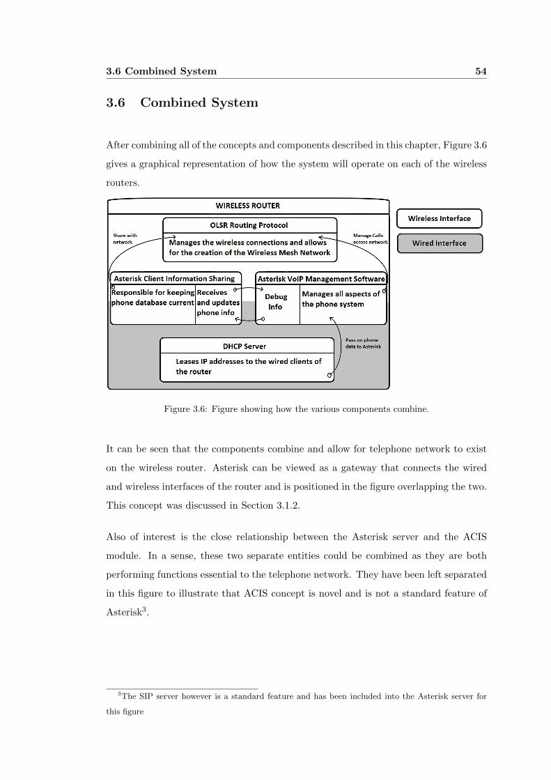
3.6 Combined System 54
3.6 Combined System
After combining all of the concepts and components described in this chapter, Figure 3.6
gives a graphical representation of how the system will operate on each of the wireless
routers.
Figure 3.6: Figure showing how the various components combine.
It can be seen that the components combine and allow for telephone network to exist
on the wireless router. Asterisk can be viewed as a gateway that connects the wired
and wireless interfaces of the router and is positioned in the figure overlapping the two.
This concept was discussed in Section 3.1.2.
Also of interest is the close relationship between the Asterisk server and the ACIS
module. In a sense, these two separate entities could be combined as they are both
performing functions essential to the telephone network. They have been left separated
in this figure to illustrate that ACIS concept is novel and is not a standard feature of
Asterisk3.
3The SIP server however is a standard feature and has been included into the Asterisk server for
this figure
3.7 Chapter Summary 55
3.7 Chapter Summary
This chapter has provided information about how the components of the proposed
system will operate as well as some of the future extensions and the considerations
that are required for their implementation. Throughout this chapter, an effort has
been made to emphasise how versatile the system is and also goes towards the various
configurations that are able to be implemented in the system.
The decisions and assumptions contained within this chapter are based upon much
community feedback as well as expert opinion. While the configuration of various
aspects of this system are suited to this application, it should be noted that this may not
be the ideal structure for all applications. Where appropriate, an alternative method
for configuration, suited to differing deployment environments is provided and it is
hoped that this paper provides a good basis for their design and implementation.
Chapter 4
Configuration of Proposed
System
This chapter covers the configuration of the network, the devices in the network and
how they combine to offer a robust telephone system. The key components of the
system include:
∙ The wireless router.
∙ The firmware for the wireless router.
∙ Software aspects that are responsible for the maintenance of the system.
∙ The IP phone.
In order for the proposed system to operate as intended, it is important that the router
is properly configured. Throughout this chapter a Microsoft Windows computer was
used to interact with the router and as such, most of the software programs mentioned
during this section of the paper specific to Microsoft Windows operating systems.
4.1 Open-WRT Settings and Configuration 57
4.1 Open-WRT Settings and Configuration
The correct configuration of the WRT54GL wireless router is fundamental to the overall
success of the proposed system. In order to implement the designs from chapter 3 many
changes to the Open-WRT firmware need to be made.
Before being able to configure the router, the custom firmware must first be loaded onto
the router and this process is described in section 4.1.1. After successfully loading the
new firmware, additional software is to be loaded onto the router and these segments
can be seen in sections 4.1.3 through 4.2.
4.1.1 Loading Open-WRT on to the WRT54GL
Replacing the firmware on the WRT54GL wireless router can be completed in two ways.
The first and easiest is to use the tool provided on the web interface of the firmware
that the router comes with. The alternative method involves sending the firmware
image to the router in the boot process. The second method is commonly used when
changing from a third party firmware to another. Both of these methods are outlined
in the next two sections:
Web Interface
In order to load the custom firmware onto the router using the web interface the router
must be connected to a computer using an RJ-45 cable. Once connected and the router
can be accessed, the following set of steps need to be followed:
1. Navigate to the web interface (usually 192.168.1.1) using an internet browser.
2. Log onto the routers’ web interface with the following default account credentials.
∙ Username: <blank>
∙ Password: root
3. Click on Administration link.
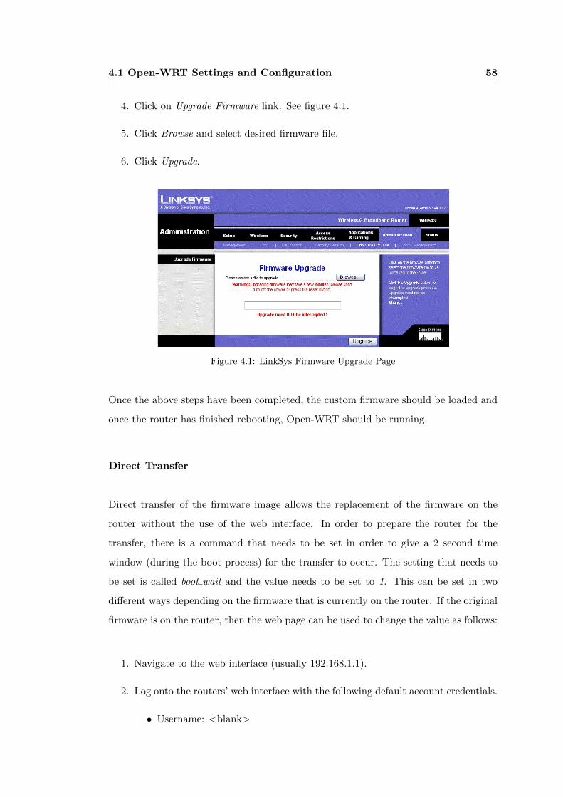
4.1 Open-WRT Settings and Configuration 58
4. Click on Upgrade Firmware link. See figure 4.1.
5. Click Browse and select desired firmware file.
6. Click Upgrade.
Figure 4.1: LinkSys Firmware Upgrade Page
Once the above steps have been completed, the custom firmware should be loaded and
once the router has finished rebooting, Open-WRT should be running.
Direct Transfer
Direct transfer of the firmware image allows the replacement of the firmware on the
router without the use of the web interface. In order to prepare the router for the
transfer, there is a command that needs to be set in order to give a 2 second time
window (during the boot process) for the transfer to occur. The setting that needs to
be set is called boot wait and the value needs to be set to 1. This can be set in two
different ways depending on the firmware that is currently on the router. If the original
firmware is on the router, then the web page can be used to change the value as follows:
1. Navigate to the web interface (usually 192.168.1.1).
2. Log onto the routers’ web interface with the following default account credentials.
∙ Username: <blank>
4.1 Open-WRT Settings and Configuration 59
∙ Password: root
3. Click on Administration link.
4. Click on Diagnostics link.
5. Locate Ping and click on the link once after entering each of the following com-
mands:
∙ ;cp${IFS}*/*/nvram${IFS}/tmp/n
∙ ;*/n${IFS}set${IFS}boot_wait=on
∙ ;*/n${IFS}commit
∙ ;*/n${IFS}show>tmp/ping.log
6. After entering the last command and clicking the Ping button, a list of output
should bee seen with the line “boot wait=on” present.
Alternatively, if there is a custom firmware already loaded onto the router, access to
the command line interface is required (see section 4.1.2). If the firmware that is on
the router is an Open-WRT distribution then the following command is needed to be
entered at the command line:
nvram set boot_wait=1
Both of the above methods set the router to wait during the boot sequence. Once this
has been completed, the actual firmware transfer is able to be completed. In order to
successfully do this, the following instructions need to be followed:
1. Open Microsoft Windows command prompt (open run program and type cmd.exe).
2. type the following command but do not enter the command.
∙ tftp -i 192.168.1.1 PUT openwrt-wrt54gs-squashfs.bin
3. Unplug power to the router.
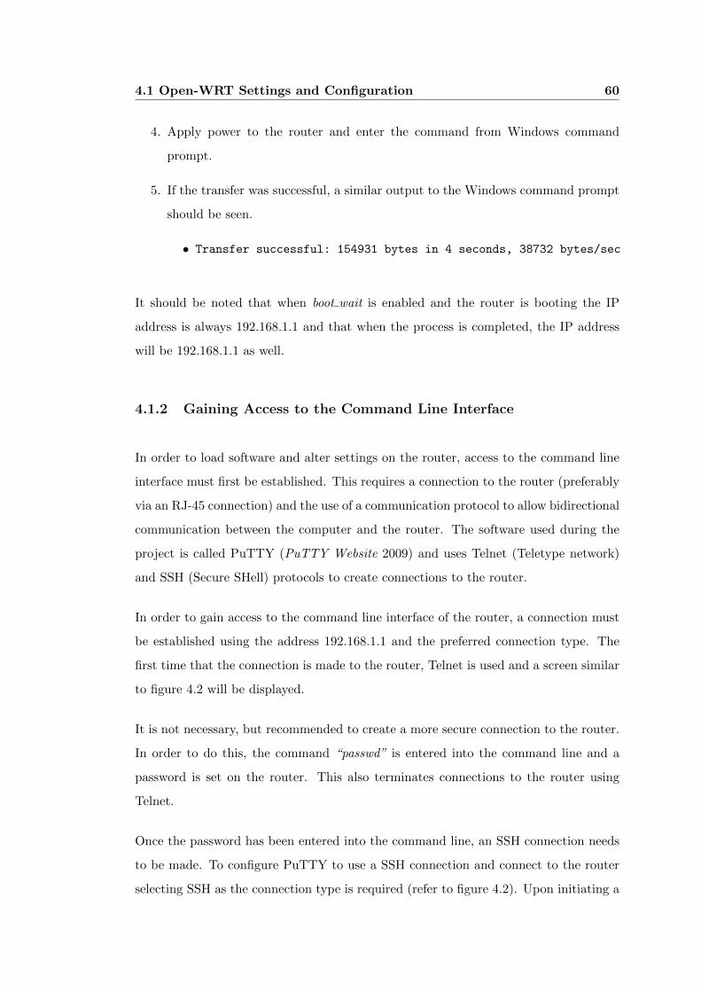
4.1 Open-WRT Settings and Configuration 60
4. Apply power to the router and enter the command from Windows command
prompt.
5. If the transfer was successful, a similar output to the Windows command prompt
should be seen.
∙ Transfer successful: 154931 bytes in 4 seconds, 38732 bytes/sec
It should be noted that when boot wait is enabled and the router is booting the IP
address is always 192.168.1.1 and that when the process is completed, the IP address
will be 192.168.1.1 as well.
4.1.2 Gaining Access to the Command Line Interface
In order to load software and alter settings on the router, access to the command line
interface must first be established. This requires a connection to the router (preferably
via an RJ-45 connection) and the use of a communication protocol to allow bidirectional
communication between the computer and the router. The software used during the
project is called PuTTY (PuTTY Website 2009) and uses Telnet (Teletype network)
and SSH (Secure SHell) protocols to create connections to the router.
In order to gain access to the command line interface of the router, a connection must
be established using the address 192.168.1.1 and the preferred connection type. The
first time that the connection is made to the router, Telnet is used and a screen similar
to figure 4.2 will be displayed.
It is not necessary, but recommended to create a more secure connection to the router.
In order to do this, the command “passwd” is entered into the command line and a
password is set on the router. This also terminates connections to the router using
Telnet.
Once the password has been entered into the command line, an SSH connection needs
to be made. To configure PuTTY to use a SSH connection and connect to the router
selecting SSH as the connection type is required (refer to figure 4.2). Upon initiating a
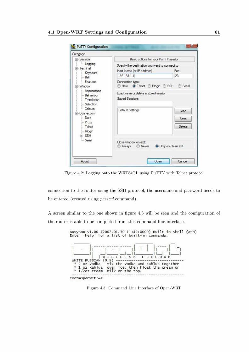
4.1 Open-WRT Settings and Configuration 61
Figure 4.2: Logging onto the WRT54GL using PuTTY with Telnet protocol
connection to the router using the SSH protocol, the username and password needs to
be entered (created using passwd command).
A screen similar to the one shown in figure 4.3 will be seen and the configuration of
the router is able to be completed from this command line interface.
Figure 4.3: Command Line Interface of Open-WRT
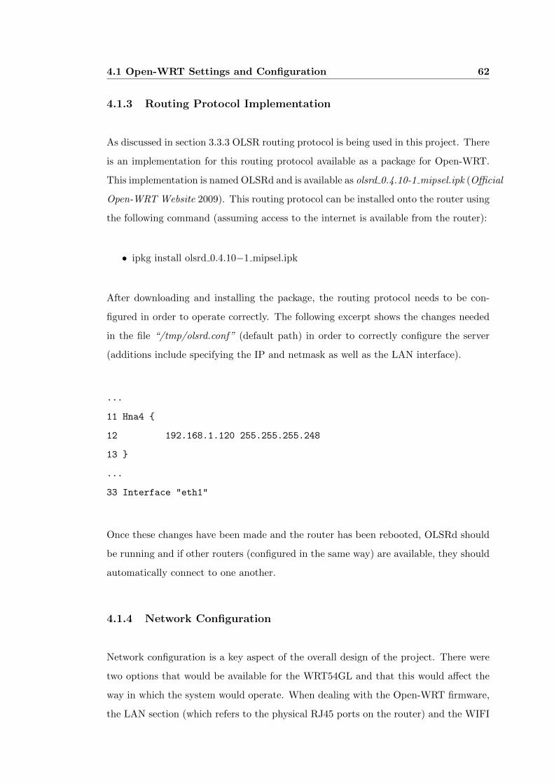
4.1 Open-WRT Settings and Configuration 62
4.1.3 Routing Protocol Implementation
As discussed in section 3.3.3 OLSR routing protocol is being used in this project. There
is an implementation for this routing protocol available as a package for Open-WRT.
This implementation is named OLSRd and is available as olsrd 0.4.10-1 mipsel.ipk (Official
Open-WRT Website 2009). This routing protocol can be installed onto the router using
the following command (assuming access to the internet is available from the router):
∙ ipkg install olsrd 0.4.10−1 mipsel.ipk
After downloading and installing the package, the routing protocol needs to be con-
figured in order to operate correctly. The following excerpt shows the changes needed
in the file “/tmp/olsrd.conf” (default path) in order to correctly configure the server
(additions include specifying the IP and netmask as well as the LAN interface).
...
11 Hna4 {
12 192.168.1.120 255.255.255.248
13 }
...
33 Interface "eth1"
Once these changes have been made and the router has been rebooted, OLSRd should
be running and if other routers (configured in the same way) are available, they should
automatically connect to one another.
4.1.4 Network Configuration
Network configuration is a key aspect of the overall design of the project. There were
two options that would be available for the WRT54GL and that this would affect the
way in which the system would operate. When dealing with the Open-WRT firmware,
the LAN section (which refers to the physical RJ45 ports on the router) and the WIFI
4.1 Open-WRT Settings and Configuration 63
section (which refers to the wireless interface of the router) can operate in bridged
mode or can be separated. By bridging the interfaces, devices on the LAN interface
interact directly with the WIFI clients. Whereas if the two interfaces remain separated,
packets sent from the LAN interface are routed through to the WIFI interface (If they
are destined for a client on that network).
A key difference here is that when the interfaces are bridged, LAN and WIFI are in the
same subnet . This is not true for the case where the two interfaces are separate, each
interface resides on different subnets. for a graphical representation of the case where
the two interfaces are separated see Figure 4.4.
Figure 4.4: Example network setup with separate LAN and WIFI
It should be noted that when the two interfaces are not bridged, that security and
routing protocols such as firewalls and Network Address Translation (NAT) traversal
can cause issues. Telephone conversations MUST be forced to go through Asterisk
servers. This is completed with the line “canreinvite=no” in sip.conf.

4.1 Open-WRT Settings and Configuration 64
LAN Configuration
The LAN ports on the WRT54GL are important to correctly configure so that the
operation of the WMN operates without issue. The hard and soft phones connected
directly to the router through the LAN interface of the router need to be able to
establish a connection to the Asterisk server that resides on the router itself.
The IP subnet can be in any range other than that of the WIFI subnet. For the
purpose of this project, it will be assumed that the subnet of the LAN interface is
192.168.1.[0-255] With the routers’ IP address being 192.168.1.120.
Effectively the devices are allowed 254 IP addresses and these are managed by a DHCP
server (see section 4.1.4) and assuming that the connected devices are configured to
run a DHCP client running (or have an available IP address in this range), they are
able to automatically lease an IP address from the router.
WIFI Configuration
One of the fundamental issues of the project is the architecture of the network. This
governs the way in which the various software features interact with each other and
also dictates the way that the hardware is to be configured. When determining the
proper structure of the network many considerations need to be taken into account.
Some of these considerations include: the network topology, mobility and
Since this application requires that wireless routers form a network that may be mobile,
it is important that the correct implementation of the routing protocols be achieved.
In order to allow the Wireless Meshed Network (WMN) to operate successfully each
of the wireless nodes need to be transmitting on the same channel and all need to be
implementing the same routing protocol. As discussed in section 3.3.3, the particular
routing protocol selected for this project was an implementation of the popular OLSRd
which is available as the package OLSRd.
4.2 Configuring Asterisk 65
DHCP server on LAN Interface
In order to create a DHCP server to manage the clients on the LAN interface of the
router, the server must be installed and configured on the router. This server is avail-
able as a package on Open-WRT called dnsmasq 2.35-1 mipsel.ipk (Official Open-WRT
Website 2009)
In order to install this package, the following command needs to be issued in the
command line interface of the router:
∙ ipkg install dnsmasq 2.35−1 mipsel.ipk
After downloading the package and installing the package the DHCP server needs to
be configured. The file “/etc/dnsmasq.conf” needs to be altered and the DHCP server
range set.
4.2 Configuring Asterisk
The configuration of the Asterisk server is a straight forward process as the maintenance
files that allow the Asterisk servers to connect to one another is handled by the Asterisk
Client Information Sharing (Section 4.3). In order to load Asterisk onto the router, the
following commands are needed to be issued in the command line interface of the router:
∙ ipkg install asterisk-mini 1.0.10-1 mipsel.ipk
Once the installation of Asterisk is complete, the router should be rebooted and the
Asterisk server should be running after booting has completed.
4.2.1 SPA901 Configuration
To allow the SPA901 IP Phones to connect to the Asterisk server that is residing on
the router that the phones are plugged into, some alterations need to be made. The
4.3 Configuration of Asterisk Client Information Sharing 66
easiest way to configure the phones is by using the web interface of the phones.
As the router should be running a DHCP server, the phone needs to be configured to
connect to this server and lease an IP address from it. There are keypad commands
that allow this to be done and they are as follows:
1. Pick up the handset.
2. Enter “****” into the keypad to enter the voice menu.
3. Enter “101#” into the keypad to enable / disable the DHCP client.
4. Enter “1#” to enable the DHCP client.
5. Enter “1” to confirm the change.
6. Hung up the handset to allow the changes to take effect.
After the above commands have been issued, the IP phone should be able to connect
to the router (or computer that is running a DHCP server) and the web interface is
able to be accessed. In the configuration page of the phone, the following settings need
to be made:
∙ The user ID in the “Subscriber Information” on the “Ext 1” tab of the page is
the phone number (extension) of the phone and a unique number needs to be set
here.
∙ The port used for SIP is set to “5060” (default).
After completing these changes and saving them, the IP phone is ready to be used in
the system.
4.3 Configuration of Asterisk Client Information Sharing
In order to allow for the design discussed in Section 3.4 two programs were written in
the C programming language. Each of the programs look after different aspect of ACIS
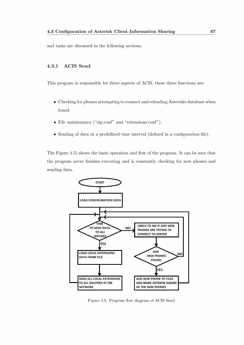
4.3 Configuration of Asterisk Client Information Sharing 67
and tasks are discussed in the following sections.
4.3.1 ACIS Send
This program is responsible for three aspects of ACIS. these three functions are:
∙ Checking for phones attempting to connect and reloading Asterisks database when
found.
∙ File maintenance (“sip.conf” and “extensions.conf”).
∙ Sending of data at a predefined time interval (defined in a configuration file).
The Figure 4.5) shows the basic operation and flow of the program. It can be seen that
the program never finishes executing and is constantly checking for new phones and
sending data.
Figure 4.5: Program flow diagram of ACIS Send
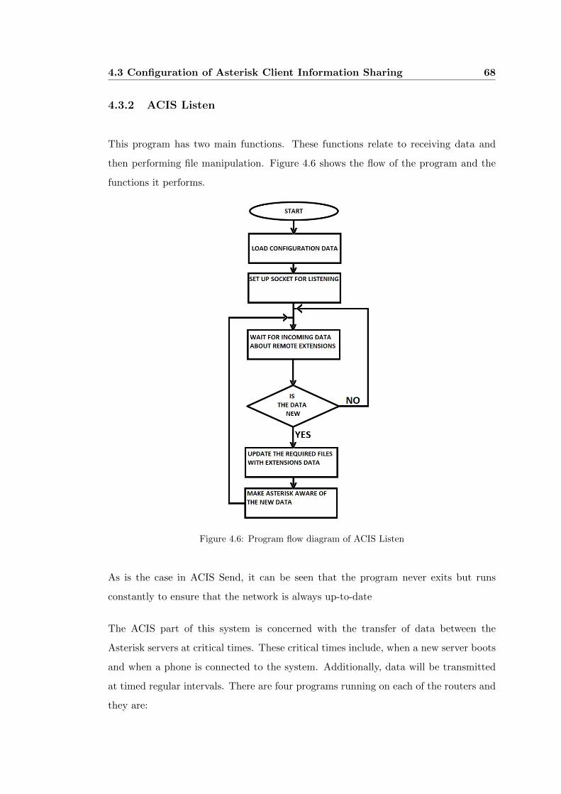
4.3 Configuration of Asterisk Client Information Sharing 68
4.3.2 ACIS Listen
This program has two main functions. These functions relate to receiving data and
then performing file manipulation. Figure 4.6 shows the flow of the program and the
functions it performs.
Figure 4.6: Program flow diagram of ACIS Listen
As is the case in ACIS Send, it can be seen that the program never exits but runs
constantly to ensure that the network is always up-to-date
The ACIS part of this system is concerned with the transfer of data between the
Asterisk servers at critical times. These critical times include, when a new server boots
and when a phone is connected to the system. Additionally, data will be transmitted
at timed regular intervals. There are four programs running on each of the routers and
they are:
4.3 Configuration of Asterisk Client Information Sharing 69
This aspect of the system requires more specific instructions as compared to the other
components that are discussed in this chapter. This is due to the fact that this aspect is
not supported or available from Open-WRT repositories but is a custom set of programs.
Each of the parts of this aspect of the system has been coded in the C programming
language and compiled in order to be compatible with the router. The source code for
the two individual programs used to carry out this function are listed in appendix C
4.3.3 Preparing the Packages
In order to enable the programs to execute on the router, a process of building a package
was needed to be completed. Open-WRT povides a Software Development Kit (SDK)
for their firmware. This SDK was placed on a Linux computer and the programs need
to be compiled from within the SDK with specialised make makefiles1.
The steps involved to create these packages included:
∙ “acissend” directory is created in the OpenWrt-SDK-Linux-i686-1/package/ di-
rectory and make file (Appendix C.5) copied here.
∙ “src” directory is created in the OpenWrt-SDK-Linux-i686-1/package/acissend
directory and make file(Appendix C.6) as well as acissend.c(Appendix C.4)copied
here.
Once the files are in the correct folders, the command “make” needs to be issued from
the OpenWrt-SDK-Linux-i686-1/ directory.
Once compiled, the programs need to be transferred to the router and stored on the
local file system. This was achieved using the Unix cutility “scp”
scp acissend_1_mipsel.ipk [email protected]:
1one to set the rules for compilation in Linux environment and one to create a package suitable for
installation on the WRT54GL

4.3 Configuration of Asterisk Client Information Sharing 70
This process was repeated for ACIS Listen and when both packages were copied to the
router, there were installed onto the router using the inbuilt “ipkg” package manager.
After copying and configuring the programs the system is ready to be tested and this
will be discussed in the next chapter.
Chapter 5
Testing of the Proposed System
This chapter investigates the performance of the system. To evaluate the network
multiple measures are used. These include:
∙ The operation of ACIS.
∙ Call capacity over the wireless links.
∙ Call quality.
∙ Delay between end users.
∙ Jitter.
∙ Packet loss.
To get an accurate idea of how the system performs, the above criteria are to be
measured during a series of different testing conditions. These will be explained and
the results provided in this chapter.
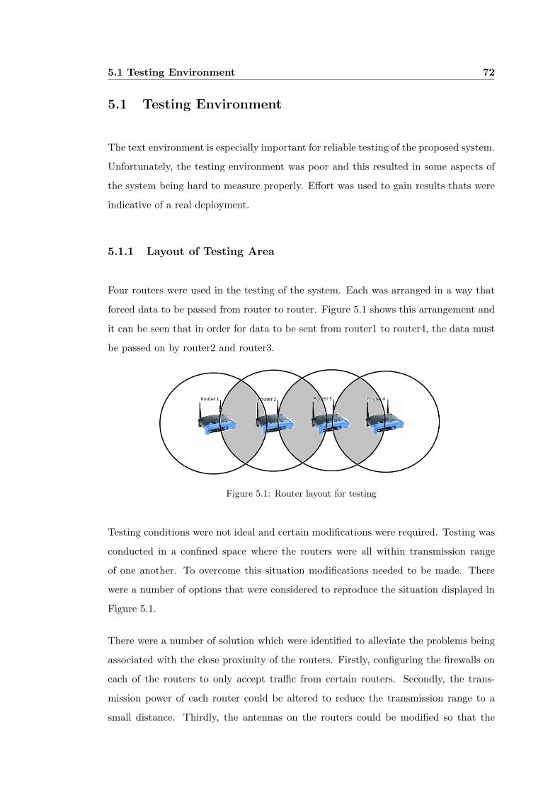
5.1 Testing Environment 72
5.1 Testing Environment
The text environment is especially important for reliable testing of the proposed system.
Unfortunately, the testing environment was poor and this resulted in some aspects of
the system being hard to measure properly. Effort was used to gain results thats were
indicative of a real deployment.
5.1.1 Layout of Testing Area
Four routers were used in the testing of the system. Each was arranged in a way that
forced data to be passed from router to router. Figure 5.1 shows this arrangement and
it can be seen that in order for data to be sent from router1 to router4, the data must
be passed on by router2 and router3.
Figure 5.1: Router layout for testing
Testing conditions were not ideal and certain modifications were required. Testing was
conducted in a confined space where the routers were all within transmission range
of one another. To overcome this situation modifications needed to be made. There
were a number of options that were considered to reproduce the situation displayed in
Figure 5.1.
There were a number of solution which were identified to alleviate the problems being
associated with the close proximity of the routers. Firstly, configuring the firewalls on
each of the routers to only accept traffic from certain routers. Secondly, the trans-
mission power of each router could be altered to reduce the transmission range to a
small distance. Thirdly, the antennas on the routers could be modified so that the
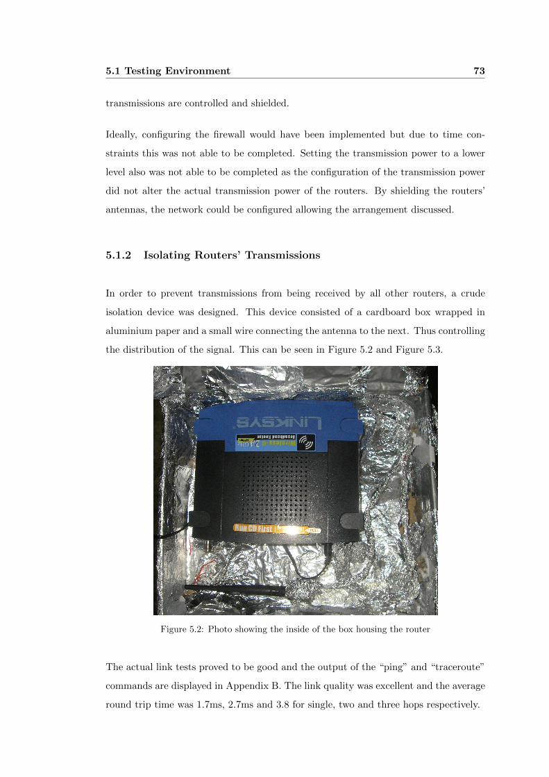
5.1 Testing Environment 73
transmissions are controlled and shielded.
Ideally, configuring the firewall would have been implemented but due to time con-
straints this was not able to be completed. Setting the transmission power to a lower
level also was not able to be completed as the configuration of the transmission power
did not alter the actual transmission power of the routers. By shielding the routers’
antennas, the network could be configured allowing the arrangement discussed.
5.1.2 Isolating Routers’ Transmissions
In order to prevent transmissions from being received by all other routers, a crude
isolation device was designed. This device consisted of a cardboard box wrapped in
aluminium paper and a small wire connecting the antenna to the next. Thus controlling
the distribution of the signal. This can be seen in Figure 5.2 and Figure 5.3.
Figure 5.2: Photo showing the inside of the box housing the router
The actual link tests proved to be good and the output of the “ping” and “traceroute”
commands are displayed in Appendix B. The link quality was excellent and the average
round trip time was 1.7ms, 2.7ms and 3.8 for single, two and three hops respectively.
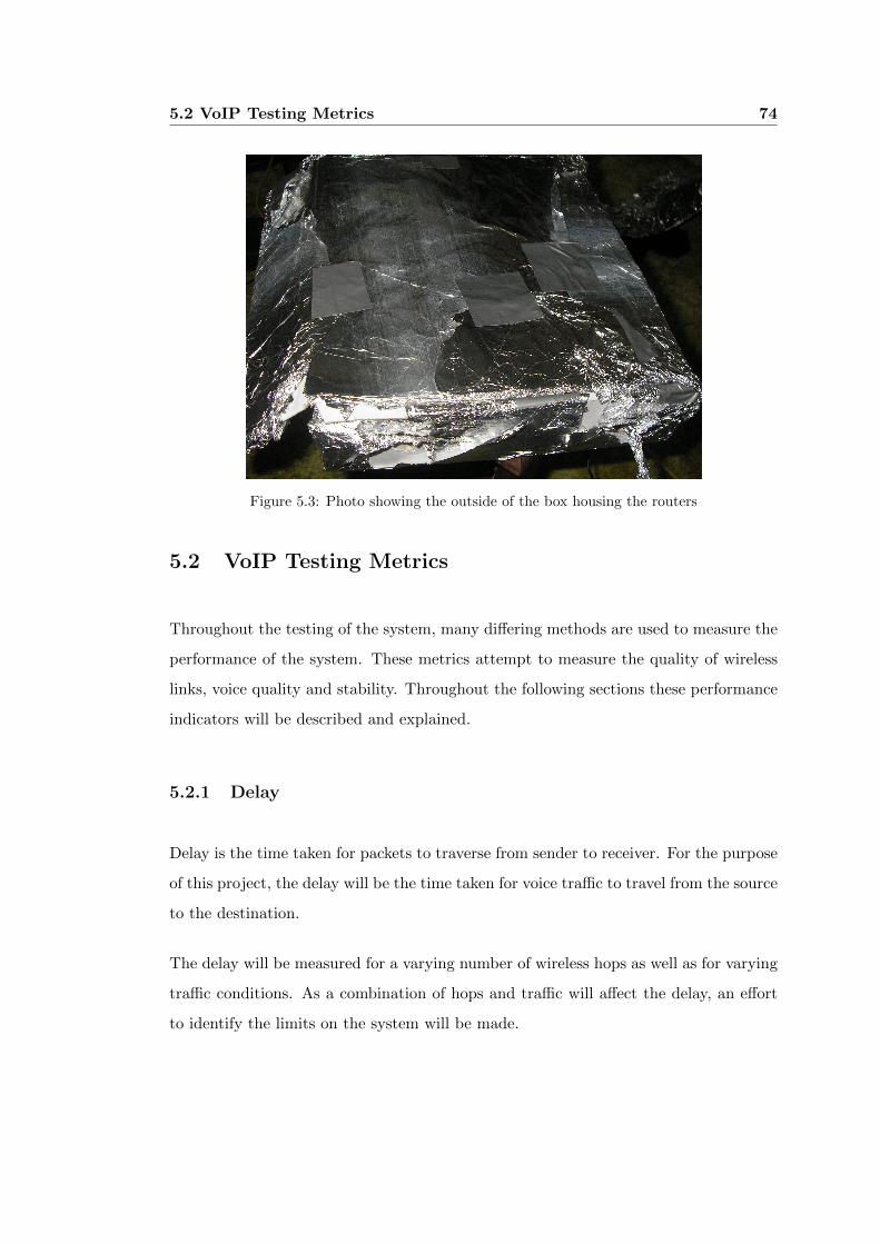
5.2 VoIP Testing Metrics 74
Figure 5.3: Photo showing the outside of the box housing the routers
5.2 VoIP Testing Metrics
Throughout the testing of the system, many differing methods are used to measure the
performance of the system. These metrics attempt to measure the quality of wireless
links, voice quality and stability. Throughout the following sections these performance
indicators will be described and explained.
5.2.1 Delay
Delay is the time taken for packets to traverse from sender to receiver. For the purpose
of this project, the delay will be the time taken for voice traffic to travel from the source
to the destination.
The delay will be measured for a varying number of wireless hops as well as for varying
traffic conditions. As a combination of hops and traffic will affect the delay, an effort
to identify the limits on the system will be made.
5.2 VoIP Testing Metrics 75
5.2.2 Jitter
Jitter is an undesirable effect of a combination of factors. Jitter, in this application,
refers to the arrival of voice packets outside of an acceptable time period.
In order for the voice to be properly reconstructed at the receiver, the packets need
to arrive at a constant rate. In the case of this project (G.771 and G.729) packets are
expected 50 times a second or every 2 milliseconds. When these packets are sent over
IP networks, there are often variances in the times that the packets arrive.
This may be due to congestion, incorrect clock frequencies and packetisation variances.
As this is a known problem there are mechanisms in place to allow for small variations
and this is called a jitter buffer. This works by delaying the playing of the audio for a
set time (usually 10 milliseconds) to allow for late packets.
When a packet arrives later than is allowed by the buffer, the packet is assumed lost
(discarded when it arrives) and the audio is played without the information. This is
obviously unacceptable as this reduces the quality of the conversation.
5.2.3 Packet Loss
Packet loss on the WMN is able to be measured with JPerf (see section 5.3.1) and
reported on. It is important that packet loss is kept to a minimum for reasons of data
integrity. Packet loss affects the quality of audio as well as the integrity of data sent
across the network.
5.2.4 Resource Use
The resource use for this project is focused on the Central Processing Unit (CPU)
and Random Access Memory (RAM) of the router. These resources are needed to be
monitored in order to make sure that router does not run out of resources and affect
the VoIP services.
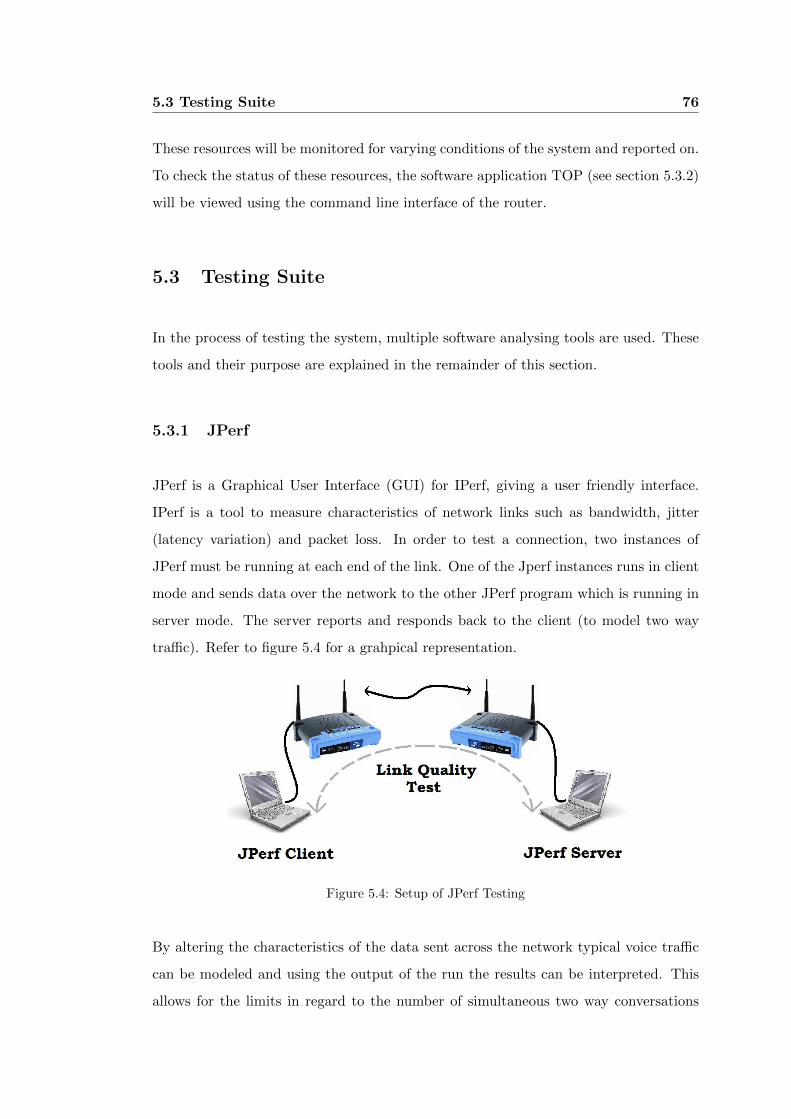
5.3 Testing Suite 76
These resources will be monitored for varying conditions of the system and reported on.
To check the status of these resources, the software application TOP (see section 5.3.2)
will be viewed using the command line interface of the router.
5.3 Testing Suite
In the process of testing the system, multiple software analysing tools are used. These
tools and their purpose are explained in the remainder of this section.
5.3.1 JPerf
JPerf is a Graphical User Interface (GUI) for IPerf, giving a user friendly interface.
IPerf is a tool to measure characteristics of network links such as bandwidth, jitter
(latency variation) and packet loss. In order to test a connection, two instances of
JPerf must be running at each end of the link. One of the Jperf instances runs in client
mode and sends data over the network to the other JPerf program which is running in
server mode. The server reports and responds back to the client (to model two way
traffic). Refer to figure 5.4 for a grahpical representation.
Figure 5.4: Setup of JPerf Testing
By altering the characteristics of the data sent across the network typical voice traffic
can be modeled and using the output of the run the results can be interpreted. This
allows for the limits in regard to the number of simultaneous two way conversations
5.3 Testing Suite 77
that can be achieved across the network.
In order to represent the typical traffic that needs to be sent across the network, a
number of calculations need to be determined. For G.711 codec the typical payload for
the packets is 160 bytes and 50 are sent a second, therefore, to determine the bandwidth
for any number of two way conversations is governed by the equation:
Bandwidth = (number of calls) x (packets per second) x (packet payload)
For the G.729 codec, the payload for each of the packets (50 per second) is 20 bytes.
As an example, the settings for 20 calls using the G.711 audio codec over the network
are configured as follows:
∙ UDP Packet Size = 160 bytes
∙ UDP Bandwidth = (20 x 50 x 160) = 160 000 bytes/sec
To determine the capacity of the simulations each of the outputs of the JPerf program
are used. The actual limits of the various outputs are listed below:
∙ Delays over 350 - 400 milliseconds are considered unacceptable.
∙ Packet loss is generally to be kept under 1% of the total packets sent.
∙ Jitter is to be kept within the limits of the jitter buffer.
5.3.2 TOP
TOP is a linux tool that shows the processes running on the system. It reports the
Central Processing Unit (CPU) usage per program as well as the system memory usage.
It is a useful tool to monitor the resource use on the router and allows for the limitations
of the router to be viewed.
The application is run from the command line interface of the router and a typical
output of the program can be seen below:
5.4 Results Obtained 78
Mem: 11448K used, 2860K free, 0K shrd, 784K buff, 4380K cached
Load average: 0.00, 0.00, 0.00 (State: S=sleeping R=running, W=waiting)
PID USER STATUS RSS PPID %CPU %MEM COMMAND
525 root R 400 522 0.7 2.7 top
521 root S 588 368 0.3 4.1 dropbear
402 root S 1420 394 0.0 9.9 asterisk
389 root S 1420 1 0.0 9.9 asterisk
401 root S 1420 394 0.0 9.9 asterisk
394 root S 1420 389 0.0 9.9 asterisk
399 root S 1420 394 0.0 9.9 asterisk
400 root S 1420 394 0.0 9.9 asterisk
450 root S 596 368 0.0 4.1 dropbear
440 root S 532 1 0.0 3.7 olsrd
451 root S 524 450 0.0 3.6 ash
522 root S 440 521 0.0 3.0 ash
420 nobody S 424 1 0.0 2.9 dnsmasq
368 root S 392 1 0.0 2.7 dropbear
315 root S 368 1 0.0 2.5 udhcpc
376 root S 364 1 0.0 2.5 httpd
1 root S 356 0 0.0 2.4 init
97 root S 356 1 0.0 2.4 init
98 root S 348 1 0.0 2.4 syslogd
5.4 Results Obtained
One hop tests were carried out using JPerf and monitoring of the resource use of the
router with TOP. The tests were run multiple times and the averages were taken. Both
the G.711 and G.729 audio codecs were simulated using data contained in Table 2.1
in Section 2.3. These tests were recorded and placed in graph that can be seen in
Figure 5.5.
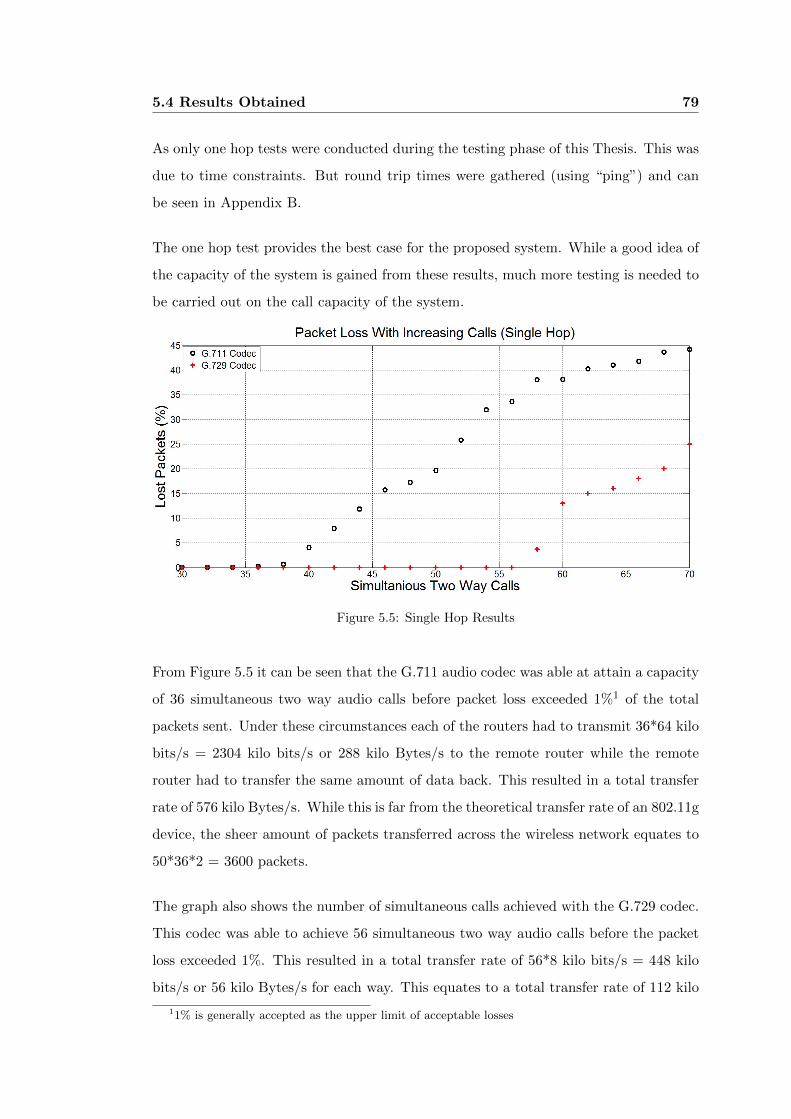
5.4 Results Obtained 79
As only one hop tests were conducted during the testing phase of this Thesis. This was
due to time constraints. But round trip times were gathered (using “ping”) and can
be seen in Appendix B.
The one hop test provides the best case for the proposed system. While a good idea of
the capacity of the system is gained from these results, much more testing is needed to
be carried out on the call capacity of the system.
Figure 5.5: Single Hop Results
From Figure 5.5 it can be seen that the G.711 audio codec was able at attain a capacity
of 36 simultaneous two way audio calls before packet loss exceeded 1%1 of the total
packets sent. Under these circumstances each of the routers had to transmit 36*64 kilo
bits/s = 2304 kilo bits/s or 288 kilo Bytes/s to the remote router while the remote
router had to transfer the same amount of data back. This resulted in a total transfer
rate of 576 kilo Bytes/s. While this is far from the theoretical transfer rate of an 802.11g
device, the sheer amount of packets transferred across the wireless network equates to
50*36*2 = 3600 packets.
The graph also shows the number of simultaneous calls achieved with the G.729 codec.
This codec was able to achieve 56 simultaneous two way audio calls before the packet
loss exceeded 1%. This resulted in a total transfer rate of 56*8 kilo bits/s = 448 kilo
bits/s or 56 kilo Bytes/s for each way. This equates to a total transfer rate of 112 kilo
11% is generally accepted as the upper limit of acceptable losses

5.4 Results Obtained 80
Bytes/s which is 38% of the total that was obtained with the G.711 codec. Taking into
account the amount of packets sent across the network with the G.711 sending 3600
and the G.729 sending 5600 it can be seen that while 38% less data was sent over the
network 155% more packets were sent.
Jitter is not shown in Figure 5.5 as it remained well within acceptable limits. This was
expected as jitter increases with the addition of more hops. Jitter has the potential
to cripple the proposed system if not carefully planned for. Jitter problems can be
alleviated to a point by increasing the size of the jitter buffer. Although this has the
undesirable effect of delaying the audio playback. When the buffer is increased, the
audio remains in the buffer for a longer period of time.
5.5 Performance of ACIS Programs 81
5.5 Performance of ACIS Programs
In order to evaluate the performance of the ACIS programs, each router was placed at
a distance apart that forced the creation of a chain arrangement2. This arrangement
is illustrated in Figure 5.1.
To ensure that each of the routers were receiving the updates, all routers were simulta-
neously logged into via a computer using “PuTTY”. Once all routers had been accessed,
and were being monitered, a phone was plugged into one of the routers while the ACIS
programs were executing.
Once the phone had been detected (from the Asterisk debugging file), all routers were
checked to see if the appropriate files had been updated as well as the Asterisk server
reloaded. To ensure that the system worked properly, the test was repeated with two
phones plugged into various routers and test calls across the wireless connections were
attempted.
5.5.1 Results of ACIS Tests
As expected, the program correctly added the information to the local files, reloaded
Asterisk with the correct information and distributed these updates to all other routers
across the network. In addition to this, at no time were the routers underload while
these tasks were being completed. While running both programs simultaneously, the
peak cpu usage was never found to be above 5% and the memory usage was very
minimal.
Most importantly, phone calls were able to be made across the network after being
detected by the ACIS system. This is the key performance criteria and it performed
extremely well.
2 the end routers were only able to communicate with one router while the middle routers were able
to communicate with the two routers around them
5.5 Performance of ACIS Programs 82
5.5.2 Observations and Known Issues
The design of the ACIS programs is previously described in Section 3.4. In the previous
section, it is stated that ACIS Send is responsible for the removal of phones that are
unplugged. Due to time constraints this was not implemented into the final program.
While this is unfortunate and needs to be implemented for future applications, this did
not prevent the concept from being proven to work.
During the process of debugging the ACIS Send program, another issue became ap-
parent. This problem presented itself when an Asterisk server failed to register with
a remote Asterisk server. Upon failing to properly register, an entry is put into the
Asterisk log file that is extremely similar to that of a failed phone registration.
To prevent this incorrect entry, a limit of eight digits for the phone extensions were
put in place3. While all extensions used in the testing of this system were under eight
digits long, practical application may need to exceed this length. Therefore, this would
need to be rectified.
3The entry that appears in the Asterisk log when a failed server registration occurs is the IP address
of the server. For example 10.0.0.10

5.6 Chapter Summary 83
5.6 Chapter Summary
This chapter has provided a basis for testing and has shown the results of stressing the
proposed system. It can be seen that the system is able to handle a reasonable amount
of telephone conversations before becoming overwhelmed.

Chapter 6
Conclusions and Further Work
The main aim of this project was to design and implement a self configuring and opti-
mised telephone network that is able to operate over wireless channels. Research into
the underlying principles of the system was conducted and the design and implementa-
tion of these components was carried out. The results obtained as part of the testing of
the system are provided in Chapter 5 are discussed in further detail within this chapter.
Also further work that would only build upon the system created in this paper are
presented towards the end of this chapter. For this system to reach its’ full potential,
the additions mentioned in this chapter need to be implemented in the future work
done in this area.
6.1 Achievement of Project Objectives 85
6.1 Achievement of Project Objectives
The Project Specification (Appendix A) lists the work that was to be completed as
part of this Thesis. With the exception of the non-overlapping numbering system (part
of Point 4 in the list) that the core programme units have been completed. The non-
overlapping number scheme was given a lot of consideration but proved too difficult
without the having a centralised management system for the WMN.
Additionally, some aspects of point 7 5.4 were completed. Point 8 is also mentioned in
Section 3.5 and a good design basis provided.
6.2 Discussion of Results
The results obtained as part of the testing of the system are promising. This Thesis has
provided a good basis for further work to be done in this field. Currently, the hardware
is able to handle creating and maintaining a small to medium sized telephone network
residing entirely on cheap hardware and freely available software components.
The key limitation of the system produced during the course of the project pertain to the
bandwidth available in wireless networks. With the limited testing it is already evident
that with more hops introduced that the number of simultaneous will fall (Possibly
dramatically). With wireless technology constantly improving1 and new methods for
increasing bandwidth constantly being researched, it is envisioned that systems similar
to the system proposed here will be implemented.
The shift towards cheaply available, high bandwidth, low latency wireless networks
are certain to gain momentum in the future. These developments will soon enable
the creation of larger, more reliable telephone networks to provided in Wireless Mesh
Networks.
1The 802.11n draft is currently in use and boast speeds up to twice that of the 802.11g standard
used in this Thesis
6.3 Further Work 86
6.3 Further Work
In order for this project to be deployed in a real situation there is much more work
needed. While the systems is extremely promising it falls short of being a complete
system. Some of the work that needs to be done can be seen in the following sections.
6.3.1 Quality of Service
Quality of Service (QoS) mechanisms would allow for the prioritising of voice data over
the network. While this would not have affected the results obtained in this paper, in
real applications there would be more traffic on the network such as Internet use and
file transfers. If the voice traffic was not allowed priority over data packets, the quality
of the conversations would reduce rapidly.
6.3.2 Use of Compressed Header Information
The use of header compression would be of great importance. This could reduce the
overhead on all voice data on the network from around 58bytes down to 24bytes on
each packet. This has obvious benefits even if only reducing the bandwidth used.
6.3.3 Added Functionality
This project has primarily focused on allowing two way telephone conversations to be
created over the network. This allows a basic telephone network to be established but
lacks some key features. Some of the most popular features are:
∙ Message banks2.
∙ Call conferencing.
∙ Call waiting.
2This has potential to be completed with the addition of an SD memory card. Refer to Section 2.8.1

6.3 Further Work 87
While these features are not included in this project, they would almost certainly be
needed in a real application. All of these features - and more - are able to be provided by
Asterisk, and with some modifications to aspects of this project, could be incorporated
into the system.
References
Adam Kowalewski website (2009). http://www.adamkowalewski.com/linksys-wrt54gl/.
Akyildiz, I. & Wang, X. (2005), ‘A survey on wireless mesh networks’, Communications
Magazine, IEEE 43, S23 – S30.
Armenia, S., Galluccio, L., Leonardi, A. & Palazzo, S. (2005), ‘Transmission of voip
traffic in multihop ad hoc ieee 802.11b networks: experimental results’, Wireless
Internet, 2005. Proceedings. First International Conference on pp. 148–155.
BBN Technologies website (2009). www.bbn.com.
Bruno, R., Conti, M. & Gregori, E. (2005), ‘Mesh networks: commodity multihop ad
hoc networks’, Communications Magazine, IEEE 43, 123–131.
Chaudhry, S., Al-Khwildi, A., Casey, Y., Aldelou, H. & Al-Raweshidy, H. (2006),
‘Wimob proactive and reactive routing protocol simulation comparison’, Informa-
tion and Communication Technologies, 2006. ICTTA ’06. 2nd 2, 2730 – 2735.
Clausen, T. & Jacquet, P. (2003), ‘Optimized link state routing protocol (olsr)’.
http://www.ietf.org/rfc/rfc3626.txt.
Gast, M. (2005), 802.11 wireless networks: the definitive guide, O’Rielly Media.
Goldsmith, A. (2005), Wireless Communications, Stanford University, California.
Google TalkTM (2009). http://www.google.com/talk/.
Hot Spot PA website (2009). http://www.hotspotpa.com/supportrouter.aspx.
REFERENCES 89
Jiang, H., Wang, P., Poor, H. & Zhuang, W. (2007), ‘Voice service support in mobile
ad hoc networks’, Global Telecommunications Conference, 2007. GLOBECOM ’07.
IEEE pp. 966 – 970.
Jun, J. & Sichitiu, M. (2003), ‘The nominal capacity of wireless mesh networks’, Wire-
less Communications, IEEE [see also IEEE Personal Communications] 10, 8–14.
Krag, T. & Bettrich, S. (2004), ‘Wireless mesh networking’.
http://www.oreillynet.com/lpt/a/4535.
Kwong, M., Cherkaoui, S. & Lefebvre, R. (2006), ‘Multiple description and multi-
path routing for robust voice transmission over ad hoc networks’, Wireless and
Mobile Computing, Networking and Communications, 2006. (WiMob’2006). IEEE
International Conference on pp. 262 – 267.
Li, H. & Singhal, M. (2005), ‘A scalable routing protocol for ad hoc networks’, Vehicular
Technology Conference, 2005. VTC 2005-Spring. 2005 IEEE 61st 4, 2498 – 2503.
Light, J.; Bhuvaneshwari, A. (2004), ‘Performance analysis of audio codecs over real-
time transmission protocol (rtp) for voice services over internet protocol’, Com-
munication Networks and Services Research, 2004. Proceedings. Second Annual
Conference on pp. 351 – 356.
Liu, C. & Wu, J. (2008), ‘Adaptive routing in dynamic ad hoc networks’, Wireless
Communications and Networking Conference, 2008. WCNC 2008. IEEE pp. 2603
– 2608.
Loscri, V., De Rango, F. & Marano, S. (2004), ‘Performance evaluation of on-demand
multipath distance vector routing protocol over two mac layers in mobile ad hoc
networks’, Wireless Communication Systems, 2004. 1st International Symposium
on pp. 413 – 417.
Loseri, V., De Rango, F. & Marano, S. (2005), ‘A correction for ad hoc on demand
multipath distance vector routing protocol (aomdv)’, Vehicular Technology Con-
ference, 2005. VTC-2005-Fall. 2005 IEEE 62nd 4, 2775 – 2779.
Lugo-Cordero, H., Lu, K., Rodriguez, D. & Kota, S. (2008), ‘A novel service-oriented
routing algorithm for wireless mesh network’, Military Communications Confer-
ence, 2008. MILCOM 2008. IEEE pp. 1–6.
REFERENCES 90
Meggelen, J., Madsen, L. & Smith, J. (2007), Asterisk: The future of telephony, O’Rielly
Media inc.
Nascimento, A., Queiroz, S., Mota, E., Galvao, L. & Nascimento, E. (2008), ‘Influence
of routing protocol on voip quality performance in wireless mesh backbone’, Next
Generation Mobile Applications, Services and Technologies, 2008. NGMAST ’08.
The Second International Conference on pp. 450 – 455.
Nicopolitidis, P., Obaidat, M., Papadimitriou, G. & Pomportsis, A. (2003), Wireless
Networks, John Wiley and Sons, LTD.
Obeidat, S. & Gupta, S. (2005), ‘Towards voice over ad hoc networks: an adaptive
scheme for packet voice communications over wireless links’, Wireless And Mo-
bile Computing, Networking And Communications, 2005. (WiMob’2005), IEEE
International Conference on 3, 245 – 252.
Official DD-WRT Website (2009). http://www.dd-wrt.com.
Official Free-WRT Website (2009). http://www.freewrt.org.
Official Open-WRT Website (2009). http://www.openwrt.org.
Official Sveasoft Website (2009). http://www.sveasoft.com.
Official Tomato Website (2009). http://www.polarcloud.com/tomato.
Perkins, C. & Royer, E. (1999), ‘Ad-hoc on-demand distance vector routing’, Mobile
Computing Systems and Applications, 1999. Proceedings. WMCSA ’99. Second
IEEE Workshop on pp. 90–100.
Pirzada, A., Wishart, R. & Portmann, M. (2007), ‘Congestion aware routing in hybrid
wireless mesh networks’, Networks, 2007. ICON 2007. 15th IEEE International
Conference on pp. 513–518.
PuTTY Website (2009). http://www.chiark.greenend.org.uk/ sgtatham/putty/.
ROBOSTUFF Website (2009). http://robostuff.com/.
Rong, B. & Qian, Y. (2008), ‘An enhanced sip proxy server for wireless voip in wireless
mesh networks’, Communications Magazine, IEEE 46, 108–113.
REFERENCES 91
Santivanez, C. & Ramanathan, R. (2003), Hazy Sighted Link State (HSLS) Routing: A
Scalable Link State Algorithm, BBN Technologies.
Siddique, M. & Kamruzzaman, J. (2008), ‘Voip call capacity over wireless mesh net-
works’, Global Telecommunications Conference, 2008. IEEE GLOBECOM 2008.
IEEE .
SkypeTM (2009). http://www.skype.com/.
SPA901 Technical Information (2009).
http://www.cisco.com/en/US/products/ps10034/index.html.
Tachtatzis, C. & Harle, D. (2008), ‘Performance evaluation of multi-path and single-
path routing protocols for mobile ad-hoc networks’, Performance Evaluation of
Computer and Telecommunication Systems, 2008. SPECTS 2008. International
Symposium on pp. 173–180.
Vaidya, B., Park, J. & Han, S. (2008), ‘Robust and secure voice transmission over
wireless mobile ad hoc network’, Ubiquitous Multimedia Computing, 2008. UMC
’08. International Symposium on pp. 175–180.
Velloso, P., Rubinstein, M. & Duarte, O. (2003), ‘Analyzing voice transmission capacity
on ad hoc networks’, Communication Technology Proceedings, 2003. ICCT 2003.
International Conference on 2, 1254 – 1257.
Vo, H. Q. & Hong, C. S. (2008), ‘Hop-count based congestion-aware multi-path routing
in wireless mesh network’, Information Networking, 2008. ICOIN 2008. Interna-
tional Conference on pp. 1–5.
VonageTM (2009). http://www.vonage.com/.
Wakamiya, N., Arakawa, S. & Murata, M. (2008), ‘Self-organizing network architecture
for scalable, adaptive, and robust networking’, Applied Sciences on Biomedical and
Communication Technologies, 2008. ISABEL ’08. First International Symposium
on pp. 1–5.
Wen, Y.-F. & Anderson, T. (2008), ‘Distributed resource and routing assignment al-
gorithms for multi-channel wmns’, Wireless and Mobile Communications, 2008.
ICWMC ’08. The Fourth International Conference on pp. 217–222.
REFERENCES 92
WRT54GL Technical Information (2009).
http://www.linksysbycisco.com/ANZ/en/products/WRT54GL.
Yuhong, Y., Ruimin, H., Haojun, A. & Yunfan, L. (2006), ‘A scalable wideband speech
coder for mobile ad hoc networks’, Wireless Communications, Networking and
Mobile Computing, 2006. WiCOM 2006.International Conference on pp. 1–4.
Zakrzewska, A., Koszalka, L. & Pozniak-Koszalka, I. (2008), ‘Performance study of
routing protocols for wireless mesh networks’, Systems Engineering, 2008. IC-
SENG ’08. 19th International Conference on pp. 331–336.

Appendix A
Project Specification

Place your project specification here.
Appendix B
WMN Muliple Hop Tests
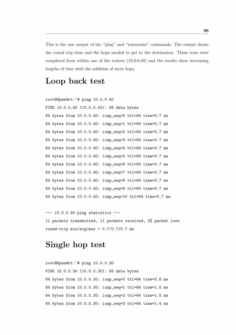
96
This is the raw output of the “ping” and “traceroute” commands. The output shows
the round trip time and the hops needed to get to the destination. These tests were
completed from within one of the routers (10.0.0.40) and the results show increasing
lengths of time with the addition of more hops.
Loop back test
root@OpenWrt:˜# ping 10.0.0.40
PING 10.0.0.40 (10.0.0.40): 56 data bytes
64 bytes from 10.0.0.40: icmp_seq=0 ttl=64 time=0.7 ms
64 bytes from 10.0.0.40: icmp_seq=1 ttl=64 time=0.7 ms
64 bytes from 10.0.0.40: icmp_seq=2 ttl=64 time=0.7 ms
64 bytes from 10.0.0.40: icmp_seq=3 ttl=64 time=0.7 ms
64 bytes from 10.0.0.40: icmp_seq=4 ttl=64 time=0.7 ms
64 bytes from 10.0.0.40: icmp_seq=5 ttl=64 time=0.7 ms
64 bytes from 10.0.0.40: icmp_seq=6 ttl=64 time=0.7 ms
64 bytes from 10.0.0.40: icmp_seq=7 ttl=64 time=0.7 ms
64 bytes from 10.0.0.40: icmp_seq=8 ttl=64 time=0.7 ms
64 bytes from 10.0.0.40: icmp_seq=9 ttl=64 time=0.7 ms
64 bytes from 10.0.0.40: icmp_seq=10 ttl=64 time=0.7 ms
--- 10.0.0.40 ping statistics ---
11 packets transmitted, 11 packets received, 0% packet loss
round-trip min/avg/max = 0.7/0.7/0.7 ms
Single hop test
root@OpenWrt:˜# ping 10.0.0.30
PING 10.0.0.30 (10.0.0.30): 56 data bytes
64 bytes from 10.0.0.30: icmp_seq=0 ttl=64 time=3.8 ms
64 bytes from 10.0.0.30: icmp_seq=1 ttl=64 time=1.5 ms
64 bytes from 10.0.0.30: icmp_seq=2 ttl=64 time=1.5 ms
64 bytes from 10.0.0.30: icmp_seq=3 ttl=64 time=1.4 ms
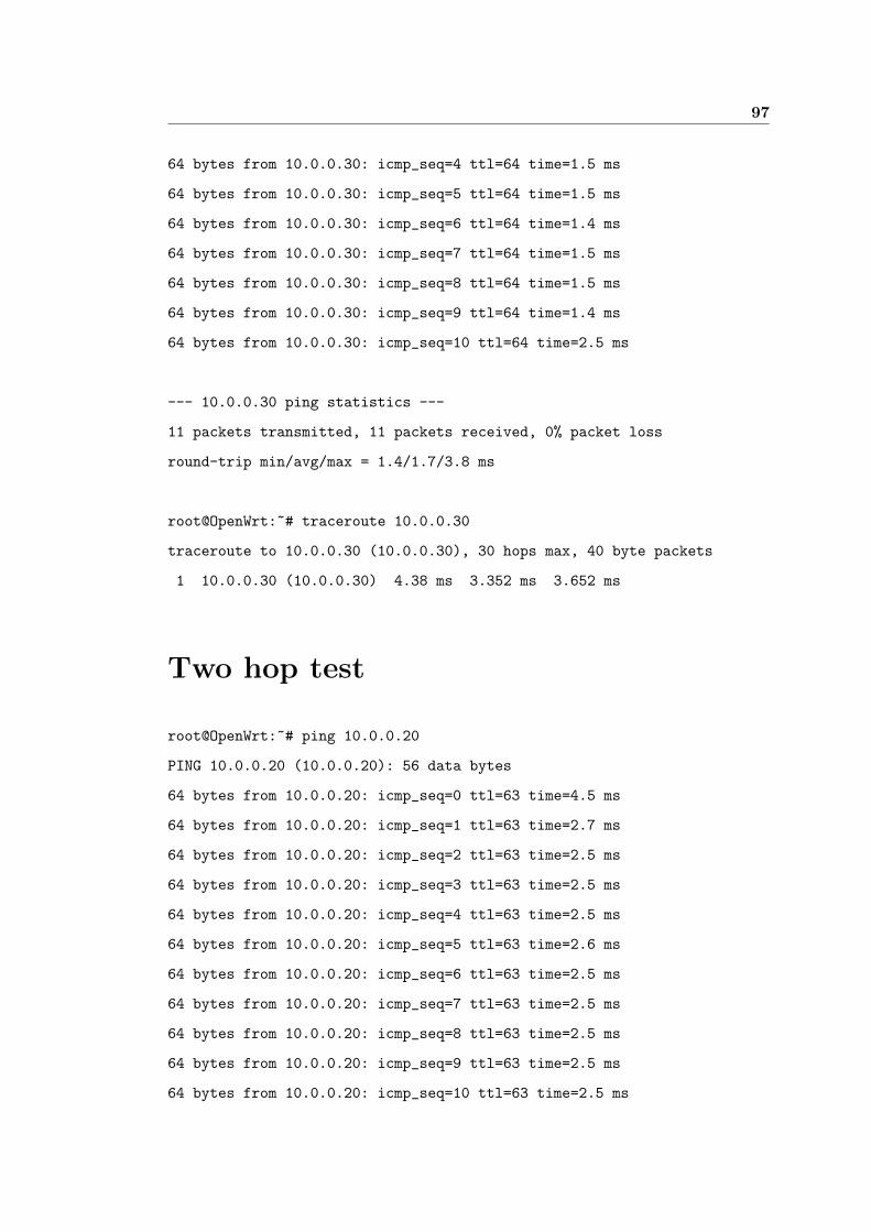
97
64 bytes from 10.0.0.30: icmp_seq=4 ttl=64 time=1.5 ms
64 bytes from 10.0.0.30: icmp_seq=5 ttl=64 time=1.5 ms
64 bytes from 10.0.0.30: icmp_seq=6 ttl=64 time=1.4 ms
64 bytes from 10.0.0.30: icmp_seq=7 ttl=64 time=1.5 ms
64 bytes from 10.0.0.30: icmp_seq=8 ttl=64 time=1.5 ms
64 bytes from 10.0.0.30: icmp_seq=9 ttl=64 time=1.4 ms
64 bytes from 10.0.0.30: icmp_seq=10 ttl=64 time=2.5 ms
--- 10.0.0.30 ping statistics ---
11 packets transmitted, 11 packets received, 0% packet loss
round-trip min/avg/max = 1.4/1.7/3.8 ms
root@OpenWrt:˜# traceroute 10.0.0.30
traceroute to 10.0.0.30 (10.0.0.30), 30 hops max, 40 byte packets
1 10.0.0.30 (10.0.0.30) 4.38 ms 3.352 ms 3.652 ms
Two hop test
root@OpenWrt:˜# ping 10.0.0.20
PING 10.0.0.20 (10.0.0.20): 56 data bytes
64 bytes from 10.0.0.20: icmp_seq=0 ttl=63 time=4.5 ms
64 bytes from 10.0.0.20: icmp_seq=1 ttl=63 time=2.7 ms
64 bytes from 10.0.0.20: icmp_seq=2 ttl=63 time=2.5 ms
64 bytes from 10.0.0.20: icmp_seq=3 ttl=63 time=2.5 ms
64 bytes from 10.0.0.20: icmp_seq=4 ttl=63 time=2.5 ms
64 bytes from 10.0.0.20: icmp_seq=5 ttl=63 time=2.6 ms
64 bytes from 10.0.0.20: icmp_seq=6 ttl=63 time=2.5 ms
64 bytes from 10.0.0.20: icmp_seq=7 ttl=63 time=2.5 ms
64 bytes from 10.0.0.20: icmp_seq=8 ttl=63 time=2.5 ms
64 bytes from 10.0.0.20: icmp_seq=9 ttl=63 time=2.5 ms
64 bytes from 10.0.0.20: icmp_seq=10 ttl=63 time=2.5 ms
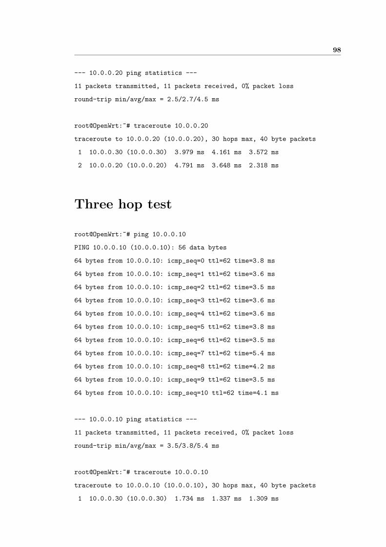
98
--- 10.0.0.20 ping statistics ---
11 packets transmitted, 11 packets received, 0% packet loss
round-trip min/avg/max = 2.5/2.7/4.5 ms
root@OpenWrt:˜# traceroute 10.0.0.20
traceroute to 10.0.0.20 (10.0.0.20), 30 hops max, 40 byte packets
1 10.0.0.30 (10.0.0.30) 3.979 ms 4.161 ms 3.572 ms
2 10.0.0.20 (10.0.0.20) 4.791 ms 3.648 ms 2.318 ms
Three hop test
root@OpenWrt:˜# ping 10.0.0.10
PING 10.0.0.10 (10.0.0.10): 56 data bytes
64 bytes from 10.0.0.10: icmp_seq=0 ttl=62 time=3.8 ms
64 bytes from 10.0.0.10: icmp_seq=1 ttl=62 time=3.6 ms
64 bytes from 10.0.0.10: icmp_seq=2 ttl=62 time=3.5 ms
64 bytes from 10.0.0.10: icmp_seq=3 ttl=62 time=3.6 ms
64 bytes from 10.0.0.10: icmp_seq=4 ttl=62 time=3.6 ms
64 bytes from 10.0.0.10: icmp_seq=5 ttl=62 time=3.8 ms
64 bytes from 10.0.0.10: icmp_seq=6 ttl=62 time=3.5 ms
64 bytes from 10.0.0.10: icmp_seq=7 ttl=62 time=5.4 ms
64 bytes from 10.0.0.10: icmp_seq=8 ttl=62 time=4.2 ms
64 bytes from 10.0.0.10: icmp_seq=9 ttl=62 time=3.5 ms
64 bytes from 10.0.0.10: icmp_seq=10 ttl=62 time=4.1 ms
--- 10.0.0.10 ping statistics ---
11 packets transmitted, 11 packets received, 0% packet loss
round-trip min/avg/max = 3.5/3.8/5.4 ms
root@OpenWrt:˜# traceroute 10.0.0.10
traceroute to 10.0.0.10 (10.0.0.10), 30 hops max, 40 byte packets
1 10.0.0.30 (10.0.0.30) 1.734 ms 1.337 ms 1.309 ms

99
2 10.0.0.20 (10.0.0.20) 2.503 ms 3.771 ms 3.494 ms
3 10.0.0.10 (10.0.0.10) 4.018 ms 3.506 ms 3.824 ms
Appendix C
Asterisk Client Information
Sharing Source Code
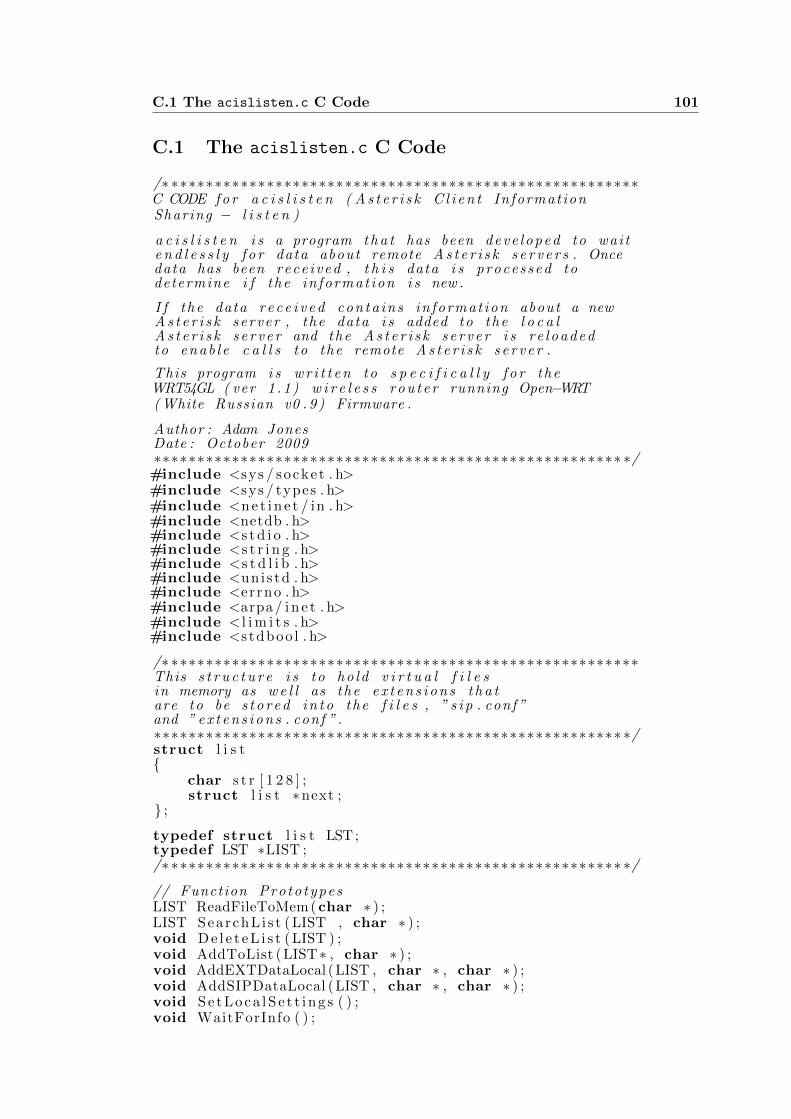
C.1 The acislisten.c C Code 101
C.1 The acislisten.c C Code
/∗ ∗∗∗∗∗∗∗∗∗∗∗∗∗∗∗∗∗∗∗∗∗∗∗∗∗∗∗∗∗∗∗∗∗∗∗∗∗∗∗∗∗∗∗∗∗∗∗∗∗∗∗∗∗∗C CODE f o r a c i s l i s t e n ( A s t e r i s k C l i e n t Informat ionSharing − l i s t e n )
a c i s l i s t e n i s a program t h a t has been deve loped to wai te n d l e s s l y f o r data about remote A s t e r i s k s e r v e r s . Oncedata has been rece ived , t h i s data i s processed todetermine i f the in format ion i s new .
I f the data r e c e i v e d cont a in s in format ion about a newA s t e r i s k server , the data i s added to the l o c a lA s t e r i s k s e r v e r and the A s t e r i s k s e r v e r i s r e l o a d e dto en ab l e c a l l s to the remote A s t e r i s k s e r v e r .
This program i s w r i t t e n to s p e c i f i c a l l y f o r theWRT54GL ( ver 1 . 1 ) w i r e l e s s r o u t e r running Open−WRT( White Russian v0 . 9 ) Firmware .
Author : Adam JonesDate : October 2009∗∗∗∗∗∗∗∗∗∗∗∗∗∗∗∗∗∗∗∗∗∗∗∗∗∗∗∗∗∗∗∗∗∗∗∗∗∗∗∗∗∗∗∗∗∗∗∗∗∗∗∗∗∗ ∗/#include <sys / socket . h>#include <sys / types . h>#include <n e t i n e t / in . h>#include <netdb . h>#include <s t d i o . h>#include <s t r i n g . h>#include <s t d l i b . h>#include <uni s td . h>#include <errno . h>#include <arpa / i n e t . h>#include < l i m i t s . h>#include <s tdboo l . h>
/∗ ∗∗∗∗∗∗∗∗∗∗∗∗∗∗∗∗∗∗∗∗∗∗∗∗∗∗∗∗∗∗∗∗∗∗∗∗∗∗∗∗∗∗∗∗∗∗∗∗∗∗∗∗∗∗This s t r u c t u r e i s to ho ld v i r t u a l f i l e sin memory as w e l l as the e x t e n s i o n s t h a tare to be s t o r e d i n t o the f i l e s , ” s i p . conf ”and ” e x t e n s i o n s . conf ” .∗∗∗∗∗∗∗∗∗∗∗∗∗∗∗∗∗∗∗∗∗∗∗∗∗∗∗∗∗∗∗∗∗∗∗∗∗∗∗∗∗∗∗∗∗∗∗∗∗∗∗∗∗∗ ∗/struct l i s t{
char s t r [ 1 2 8 ] ;struct l i s t ∗next ;
} ;
typedef struct l i s t LST;typedef LST ∗LIST ;/∗ ∗∗∗∗∗∗∗∗∗∗∗∗∗∗∗∗∗∗∗∗∗∗∗∗∗∗∗∗∗∗∗∗∗∗∗∗∗∗∗∗∗∗∗∗∗∗∗∗∗∗∗∗ ∗/
// Function Proto typesLIST ReadFileToMem (char ∗ ) ;LIST SearchL i s t (LIST , char ∗ ) ;void D e l e t e L i s t (LIST ) ;void AddToList (LIST∗ , char ∗ ) ;void AddEXTDataLocal (LIST , char ∗ , char ∗ ) ;void AddSIPDataLocal (LIST , char ∗ , char ∗ ) ;void S e t L o ca l S e t t i ng s ( ) ;void WaitForInfo ( ) ;

C.1 The acislisten.c C Code 102
void PrintDataToFile (LIST , char ∗ ) ;void ProcessData (char ∗ , char ∗ ) ;
// Globa l V a r i a b l e schar LOCALIP [ 1 6 ] ;char CODEC[ 2 0 ] ;char EXT[ 5 0 ] ;char MESSAGES[ 5 0 ] ;char SIP [ 5 0 ] ;
/∗ ∗∗∗∗∗∗∗∗∗∗∗∗∗∗∗∗∗∗∗∗∗∗∗∗∗∗∗∗∗∗∗∗∗∗∗∗∗∗∗∗∗∗∗∗∗∗∗∗∗∗∗∗∗∗The main f u n c t i o n i s r e s p o n s i b l e f o rr e t r i e v i n g the c o n t e n t s o f the g l o b a lv a r i a b l e s and a l s o f o r s t a r t i n g thew a i t i n g pro ces s .INPUT:
( none )OUTPUT:
( none )∗∗∗∗∗∗∗∗∗∗∗∗∗∗∗∗∗∗∗∗∗∗∗∗∗∗∗∗∗∗∗∗∗∗∗∗∗∗∗∗∗∗∗∗∗∗∗∗∗∗∗∗∗∗ ∗/int main ( ){
S e t L o ca l S e t t i n g s ( ) ;WaitForInfo ( ) ;
}/∗ ∗∗∗∗∗∗∗∗∗∗∗∗∗∗∗∗∗∗∗∗∗∗∗∗∗∗∗∗∗∗∗∗∗∗∗∗∗∗∗∗∗∗∗∗∗∗∗∗∗∗∗∗ ∗/
/∗ ∗∗∗∗∗∗∗∗∗∗∗∗∗∗∗∗∗∗∗∗∗∗∗∗∗∗∗∗∗∗∗∗∗∗∗∗∗∗∗∗∗∗∗∗∗∗∗∗∗∗∗∗∗This f u n c t i o n c r e a t e s a s o c k e t f o rl i s t e n i n g . Upon r e c e i v i n g a data itemthe f u n c t i o n ” ProcessData ()” i s c a l l e dand the data i s processed and added tothe a p p r o p r i a t e f i l e s . This f u n c t i o nw i l l l oop i n d e f i n a t e l y w a i t i n g f o rin format ion .INPUT:
( none )OUTPUT:
( none )∗∗∗∗∗∗∗∗∗∗∗∗∗∗∗∗∗∗∗∗∗∗∗∗∗∗∗∗∗∗∗∗∗∗∗∗∗∗∗∗∗∗∗∗∗∗∗∗∗∗∗∗∗∗ ∗/void WaitForInfo ( ){
// Local v a r i a b l e d e c l a r a t i o nchar buf [ 4 0 ] ;int sock , length , fromlen , n , r e c e i v e d =0;struct sockaddr in s e r v e r ;struct sockaddr in from ;
// Get s o c k e t f o r l i s t e n i n gsock=socket (AF INET , SOCK DGRAM, 0 ) ;i f ( sock <0) e r r o r ( ”Opening socke t ” ) ;
l ength = s izeof ( s e r v e r ) ;bzero(&server , l ength ) ;f romlen = s izeof ( struct sockaddr in ) ;
// Set the paramters o f the s o c k e t .s e r v e r . s i n f a m i l y=AF INET ;s e r v e r . s i n addr . s addr=INADDR ANY;s e r v e r . s i n p o r t=htons (321 30 ) ;
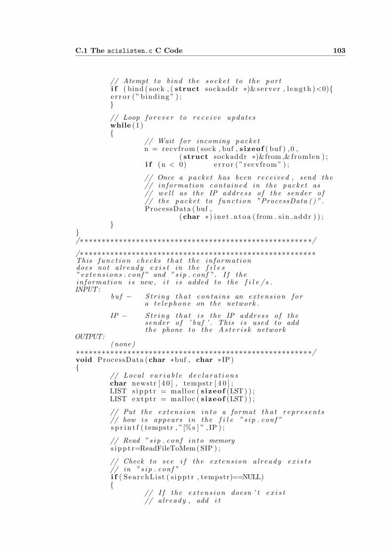
C.1 The acislisten.c C Code 103
// Atempt to bind the s o c k e t to the por ti f ( bind ( sock , ( struct sockaddr ∗)& server , l ength )<0){e r r o r ( ” binding ” ) ;}
// Loop f o r e v e r to r e c e i v e updateswhile (1 ){
// Wait f o r incoming packe tn = recvfrom ( sock , buf , s izeof ( buf ) , 0 ,
( struct sockaddr ∗)&from ,& fromlen ) ;i f (n < 0) e r r o r ( ” recvfrom ” ) ;
// Once a packe t has been rece ived , send the// in format ion conta ined in the packe t as// w e l l as the IP address o f the sender o f// the packe t to f u n c t i o n ” ProcessData ( ) ” .ProcessData ( buf ,
(char ∗) i n e t n t o a ( from . s in addr ) ) ;}
}/∗ ∗∗∗∗∗∗∗∗∗∗∗∗∗∗∗∗∗∗∗∗∗∗∗∗∗∗∗∗∗∗∗∗∗∗∗∗∗∗∗∗∗∗∗∗∗∗∗∗∗∗∗∗ ∗/
/∗ ∗∗∗∗∗∗∗∗∗∗∗∗∗∗∗∗∗∗∗∗∗∗∗∗∗∗∗∗∗∗∗∗∗∗∗∗∗∗∗∗∗∗∗∗∗∗∗∗∗∗∗∗∗∗This f u n c t i o n checks t h a t the in format iondoes not a l r e a d y e x i s t in the f i l e s” e x t e n s i o n s . conf ” and ” s i p . conf ” . I f thein format ion i s new , i t i s added to the f i l e / s .INPUT:
bu f − S t r i n g t h a t c ont a ins an e x t e n s i o n f o ra t e l e p h o n e on the network .
IP − S t r i n g t h a t i s the IP address o f thesender o f ’ bu f ’ . This i s used to addthe phone to the A s t e r i s k network
OUTPUT:( none )
∗∗∗∗∗∗∗∗∗∗∗∗∗∗∗∗∗∗∗∗∗∗∗∗∗∗∗∗∗∗∗∗∗∗∗∗∗∗∗∗∗∗∗∗∗∗∗∗∗∗∗∗∗∗ ∗/void ProcessData (char ∗buf , char ∗IP ){
// Local v a r i a b l e d e c l a r a t i o n schar newstr [ 4 0 ] , tempstr [ 4 0 ] ;LIST s i p p t r = mal loc ( s izeof (LST ) ) ;LIST extpt r = mal loc ( s izeof (LST ) ) ;
// Put the e x t e n s i o n i n t o a format t h a t r e p r e s e n t s// how i s appears in the f i l e ” s i p . conf ”s p r i n t f ( tempstr , ”[%s ] ” , IP ) ;
// Read ” s i p . conf i n t o memorys i p p t r=ReadFileToMem ( SIP ) ;
// Check to see i f the e x t e n s i o n a l r e a d y e x i s t s// in ” s i p . conf ”i f ( SearchL i s t ( s ippt r , tempstr)==NULL){
// I f the e x t e n s i o n doesn ’ t e x i s t// a lready , add i t
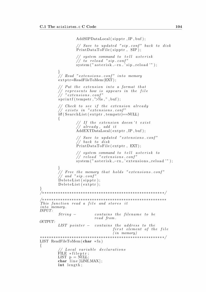
C.1 The acislisten.c C Code 104
AddSIPDataLocal ( s ippt r , IP , buf ) ;
// Save to updated ” s i p . conf ” back to d i s kPrintDataToFile ( s ippt r , SIP ) ;
// system command to t e l l a s t e r i s k// to r e l o a d ” s i p . conf ”system ( ” a s t e r i s k −rx ’ s i p r e l oad ’ ” ) ;
}// Read ” e x t e n s i o n s . conf ” i n t o memoryextpt r=ReadFileToMem (EXT) ;
// Put the e x t e n s i o n i n t o a format t h a t// r e p r e s e n t s how i s appears in the f i l e// ” e x t e n s i o n s . conf ”s p r i n t f ( tempstr , ”>%s , ” , buf ) ;
// Check to see i f the e x t e n s i o n a l r e a d y// e x i s t s in ” e x t e n s i o n s . conf ”i f ( SearchL i s t ( extptr , tempstr)==NULL){
// I f the e x t e n s i o n doesn ’ t e x i s t// a lready , add i tAddEXTDataLocal ( extptr , IP , buf ) ;
// Save to updated ” e x t e n s i o n s . conf ”// back to d i s kPrintDataToFile ( extptr , EXT) ;
// system command to t e l l a s t e r i s k to// r e l o a d ” e x t e n s i o n s . conf ”system ( ” a s t e r i s k −rx ’ ex t en s i on s r e l oad ’ ” ) ;
}// Free the memory t h a t h o l d s ” e x t e n s i o n s . conf ”// and ” s i p . conf ”D e l e t e L i s t ( s i p p t r ) ;D e l e t e L i s t ( extpt r ) ;
}/∗ ∗∗∗∗∗∗∗∗∗∗∗∗∗∗∗∗∗∗∗∗∗∗∗∗∗∗∗∗∗∗∗∗∗∗∗∗∗∗∗∗∗∗∗∗∗∗∗∗∗∗∗∗ ∗/
/∗ ∗∗∗∗∗∗∗∗∗∗∗∗∗∗∗∗∗∗∗∗∗∗∗∗∗∗∗∗∗∗∗∗∗∗∗∗∗∗∗∗∗∗∗∗∗∗∗∗∗∗∗∗∗∗This f u n c t i o n read a f i l e and s t o r e s i ti n t o memory .INPUT:
S t r i n g − co nta i ns the f i l ename to beread from .
OUTPUT:LIST p o i n t e r − co nta i ns the address to the
f i r s t e lement o f the f i l e( in memory)
∗∗∗∗∗∗∗∗∗∗∗∗∗∗∗∗∗∗∗∗∗∗∗∗∗∗∗∗∗∗∗∗∗∗∗∗∗∗∗∗∗∗∗∗∗∗∗∗∗∗∗∗∗∗ ∗/LIST ReadFileToMem (char ∗ fn ){
// Local v a r i a b l e d e c l a r a t i o n sFILE ∗ f i l e p t r ;LIST p = NULL;char l i n e [LINE MAX ] ;int l ength ;
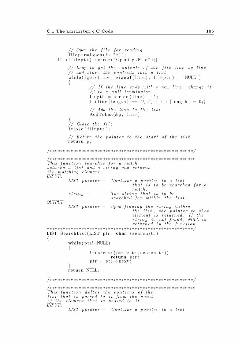
C.1 The acislisten.c C Code 105
// Open the f i l e f o r readingf i l e p t r=fopen ( fn , ” r ” ) ;
i f ( ! f i l e p t r ) { e r r o r ( ”Opening F i l e ” ) ; }
// Loop to g e t the c o n t e n t s o f the f i l e l i n e−by−l i n e// and s t o r e the c o n t e n t s i n t o a l i s twhile ( f g e t s ( l i n e , s izeof ( l i n e ) , f i l e p t r ) != NULL ){
// I f the l i n e ends wi th a new l i n e , change i t// to a n u l l t erminatorl ength = s t r l e n ( l i n e ) − 1 ;i f ( l i n e [ l ength ] == ’ ∖n ’ ) { l i n e [ l ength ] = 0 ;}
// Add the l i n e to the l i s tAddToList(&p , l i n e ) ;
}// Close the f i l ef c l o s e ( f i l e p t r ) ;
// Return the p o i n t e r to the s t a r t o f the l i s t .return p ;
}/∗ ∗∗∗∗∗∗∗∗∗∗∗∗∗∗∗∗∗∗∗∗∗∗∗∗∗∗∗∗∗∗∗∗∗∗∗∗∗∗∗∗∗∗∗∗∗∗∗∗∗∗∗∗ ∗/
/∗ ∗∗∗∗∗∗∗∗∗∗∗∗∗∗∗∗∗∗∗∗∗∗∗∗∗∗∗∗∗∗∗∗∗∗∗∗∗∗∗∗∗∗∗∗∗∗∗∗∗∗∗∗∗∗This f u n c t i o n s e a r c h e s f o r a matchbetween a l i s t and a s t r i n g and r e t u r n sthe matching element .INPUT:
LIST p o i n t e r − Contains a p o i n t e r to a l i s tt h a t i s to be searched f o r amatch .
s t r i n g − The s t r i n g t h a t i s to besearched f o r w i t h i n the l i s t .
OUTPUT:LIST p o i n t e r − Upon f i n d i n g the s t r i n g w i t h i n
the l i s t , the p o i n t e r to t h a te lement i s re turned . I f thes t r i n g i s not found , NULL i sre turned by the f u n c t i o n .
∗∗∗∗∗∗∗∗∗∗∗∗∗∗∗∗∗∗∗∗∗∗∗∗∗∗∗∗∗∗∗∗∗∗∗∗∗∗∗∗∗∗∗∗∗∗∗∗∗∗∗∗∗∗ ∗/LIST SearchL i s t (LIST ptr , char ∗ s e a r c h s t r ){
while ( ptr !=NULL){
i f ( s t r s t r ( ptr−>s t r , s e a r c h s t r ) )return ptr ;
ptr = ptr−>next ;}return NULL;
}/∗ ∗∗∗∗∗∗∗∗∗∗∗∗∗∗∗∗∗∗∗∗∗∗∗∗∗∗∗∗∗∗∗∗∗∗∗∗∗∗∗∗∗∗∗∗∗∗∗∗∗∗∗∗ ∗/
/∗ ∗∗∗∗∗∗∗∗∗∗∗∗∗∗∗∗∗∗∗∗∗∗∗∗∗∗∗∗∗∗∗∗∗∗∗∗∗∗∗∗∗∗∗∗∗∗∗∗∗∗∗∗∗∗This f u n c t i o n d e l t e s the c o n t e n t s o f thel i s t t h a t i s passed to i t from the p o i n to f the e lement t h a t i s passed to i t .INPUT:
LIST p o i n t e r − Contains a p o i n t e r to a l i s t
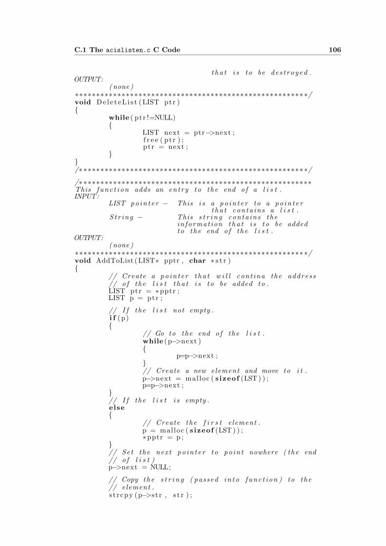
C.1 The acislisten.c C Code 106
t h a t i s to be d e s t r o y e d .OUTPUT:
( none )∗∗∗∗∗∗∗∗∗∗∗∗∗∗∗∗∗∗∗∗∗∗∗∗∗∗∗∗∗∗∗∗∗∗∗∗∗∗∗∗∗∗∗∗∗∗∗∗∗∗∗∗∗∗ ∗/void D e l e t e L i s t (LIST ptr ){
while ( ptr !=NULL){
LIST next = ptr−>next ;f r e e ( ptr ) ;ptr = next ;
}}/∗ ∗∗∗∗∗∗∗∗∗∗∗∗∗∗∗∗∗∗∗∗∗∗∗∗∗∗∗∗∗∗∗∗∗∗∗∗∗∗∗∗∗∗∗∗∗∗∗∗∗∗∗∗ ∗/
/∗ ∗∗∗∗∗∗∗∗∗∗∗∗∗∗∗∗∗∗∗∗∗∗∗∗∗∗∗∗∗∗∗∗∗∗∗∗∗∗∗∗∗∗∗∗∗∗∗∗∗∗∗∗∗∗This f u n c t i o n adds an entry to the end o f a l i s t .INPUT:
LIST p o i n t e r − This i s a p o i n t e r to a p o i n t e rt h a t co nta ins a l i s t .
S t r i n g − This s t r i n g con ta i ns thein format ion t h a t i s to be addedto the end o f the l i s t .
OUTPUT:( none )
∗∗∗∗∗∗∗∗∗∗∗∗∗∗∗∗∗∗∗∗∗∗∗∗∗∗∗∗∗∗∗∗∗∗∗∗∗∗∗∗∗∗∗∗∗∗∗∗∗∗∗∗∗∗ ∗/void AddToList (LIST∗ pptr , char ∗ s t r ){
// Create a p o i n t e r t h a t w i l l cont ina the address// o f the l i s t t h a t i s to be added to .LIST ptr = ∗pptr ;LIST p = ptr ;
// I f the l i s t not empty .i f (p){
// Go to the end o f the l i s t .while (p−>next ){
p=p−>next ;}// Create a new element and move to i t .p−>next = mal loc ( s izeof (LST ) ) ;p=p−>next ;
}// I f the l i s t i s empty .else{
// Create the f i r s t e lement .p = mal loc ( s izeof (LST ) ) ;∗pptr = p ;
}// Set the next p o i n t e r to p o i n t nowhere ( the end// o f l i s t )p−>next = NULL;
// Copy the s t r i n g ( passed i n t o f u n c t i o n ) to the// element .s t r cpy (p−>s t r , s t r ) ;

C.1 The acislisten.c C Code 107
}/∗ ∗∗∗∗∗∗∗∗∗∗∗∗∗∗∗∗∗∗∗∗∗∗∗∗∗∗∗∗∗∗∗∗∗∗∗∗∗∗∗∗∗∗∗∗∗∗∗∗∗∗∗∗ ∗/
/∗ ∗∗∗∗∗∗∗∗∗∗∗∗∗∗∗∗∗∗∗∗∗∗∗∗∗∗∗∗∗∗∗∗∗∗∗∗∗∗∗∗∗∗∗∗∗∗∗∗∗∗∗∗∗∗This f u n c t i o n adds a e x t e n s i o n to the” e x t e n s i o n s . conf ” f i l e ( h e l d in memory ) .INPUT:
LIST p o i n t e r − This p o i n t e r p o i n t s to a l i s tt h a t co nta ins ” e x t e n s i o n s . conf ”
S t r i n g − This s t r i n g con ta i ns thee x t e n s i o n t h a t i s to be addedto ” e x t e n s i o n s . conf ”
OUTPUT:( none )
∗∗∗∗∗∗∗∗∗∗∗∗∗∗∗∗∗∗∗∗∗∗∗∗∗∗∗∗∗∗∗∗∗∗∗∗∗∗∗∗∗∗∗∗∗∗∗∗∗∗∗∗∗∗ ∗/void AddEXTDataLocal (LIST ptr , char ∗IP , char ∗ s t r ){
// Local v a r i a b l e d e c l a r a t i o n s .LIST pstart , tempptr , newentry=mal loc ( s izeof (LST ) ) ;char tempstr [ 6 0 ] ;
// Find the l i n e t h a t h o l d s ” [ remote ] ’ptr=SearchL i s t ( ptr , ” [ remote ] ” ) ;
// Record the s t a r t p o s i t i o n o f the new e n t r i e s .p s t a r t=ptr ;
// Set the p o i n t e r s so t h a t tmpstr i s// i n s e r t e d ’ here ’ .newentry−>next = ptr−>next ;ptr−>next = newentry ;ptr = ptr−>next ;
// Copy the s t r i n g i n t o the newly a l l o c a t e d space .s p r i n t f ( tempstr , ” exten=>%s , 1 ,NoOp( ) ” , s t r ) ;s t r cpy ( newentry−>s t r , tempstr ) ;
// Set the p o i n t e r s so t h a t tmpstr i s// i n s e r t e d ’ here ’ .newentry = mal loc ( s izeof (LST ) ) ;newentry−>next = ptr−>next ;ptr−>next = newentry ;ptr = ptr−>next ;
// Copy the s t r i n g i n t o the newly a l l o c a t e d space .s p r i n t f ( tempstr , ” exten=>%s , 2 , Dia l ( SIP/%s /${EXTEN}) ” ,
s t r , IP ) ;s t r cpy ( newentry−>s t r , tempstr ) ;
// Set the p o i n t e r s so t h a t tmpstr i s// i n s e r t e d ’ here ’ .newentry = mal loc ( s izeof (LST ) ) ;newentry−>next = ptr−>next ;ptr−>next = newentry ;ptr = ptr−>next ;
// Copy the s t r i n g i n t o the newly a l l o c a t e d space .s p r i n t f ( tempstr , ” exten=>%s , 3 , HangUp()∖n” , s t r ) ;s t r cpy ( newentry−>s t r , tempstr ) ;
newentry = mal loc ( s izeof (LST ) ) ;

C.1 The acislisten.c C Code 108
// Find the l i n e t h a t h o l d s ” [ remote ] ’while ( ! s t r s t r ( ptr−>next−>s t r , ” [ phones ] ” ) ){
ptr=ptr−>next ;}
// Create a s t r i n g to t e s t f o r the A s t e r i s k// s e r v e r s presence .s p r i n t f ( tempstr , ”[% s incoming ] ” , IP ) ;// I f t h e r e i s not a l r e a d y an entry f o r t h i s// a s t e r i s k s e r v e r .i f ( SearchL i s t ( pstar t , tempstr)==NULL){
// Add in format ion ’ here ’ f o r the s e r v e r .tempptr = mal loc ( s izeof (LST ) ) ;tempptr−>next = ptr−>next ;s p r i n t f ( tempstr , ”[% s incoming ] ” , IP ) ;s t r cpy ( tempptr−>s t r , tempstr ) ;ptr−>next = tempptr ;ptr = ptr−>next ;
tempptr = mal loc ( s izeof (LST ) ) ;tempptr−>next = ptr−>next ;s p r i n t f ( tempstr , ” i n c lude=>i n t e r n a l ∖n” ) ;s t r cpy ( tempptr−>s t r , tempstr ) ;ptr−>next = tempptr ;ptr = ptr−>next ;
}}/∗ ∗∗∗∗∗∗∗∗∗∗∗∗∗∗∗∗∗∗∗∗∗∗∗∗∗∗∗∗∗∗∗∗∗∗∗∗∗∗∗∗∗∗∗∗∗∗∗∗∗∗∗∗ ∗/
/∗ ∗∗∗∗∗∗∗∗∗∗∗∗∗∗∗∗∗∗∗∗∗∗∗∗∗∗∗∗∗∗∗∗∗∗∗∗∗∗∗∗∗∗∗∗∗∗∗∗∗∗∗∗∗∗This f u n c t i o n adds a e x t e n s i o n to the ” s i p . conf ”f i l e ( h e l d in memory ) .
INPUT:LIST p o i n t e r − This p o i n t e r p o i n t s to a l i s t
t h a t co nta ins ” s i p . conf ”S t r i n g − This s t r i n g con ta i ns the
e x t e n s i o n t h a t i s to be addedto ” s i p . conf ”
OUTPUT:( none )
∗∗∗∗∗∗∗∗∗∗∗∗∗∗∗∗∗∗∗∗∗∗∗∗∗∗∗∗∗∗∗∗∗∗∗∗∗∗∗∗∗∗∗∗∗∗∗∗∗∗∗∗∗∗ ∗/void AddSIPDataLocal (LIST ptr , char ∗IP , char ∗ s t r ){
// Local v a r i a b l e d e c l a r a t i o n s .char tempstr [ 6 0 ] ;LIST newentry , s t a r t p t r=ptr ;bool a l r e ad yE x i s t s=f a l s e ;
// Find the p o s i t i o n o f r e g i s t e rwhile ( ptr=SearchL i s t ( ptr , ” r e g i s t e r ” ) ){
// I f the IP address i s r e g i s t e r e d .i f ( s t r s t r ( ptr−>s t r , IP ) ){
// Record t h a t the r e g i s t r a t i o n has a l r e a d y// been entereda l r e ad yE x i s t s=true ;

C.1 The acislisten.c C Code 109
}// Move to the next l i s t item .ptr=ptr−>next ;
}// I f t h e r e i s no r e g i s t r a t i o n in format ion in// the f i l e .i f ( ! a l r e ad yE x i s t s ){
// Add r e g i s t r a t i o n d e t a i l s .newentry = mal loc ( s izeof (LST ) ) ;s p r i n t f ( tempstr , ” r e g i s t e r=>%s : welcome@%s/%s ” ,
LOCALIP, IP , IP ) ;
s t r cpy ( newentry−>s t r , tempstr ) ;newentry−>next = ptr−>next ;ptr−>next = newentry ;
}// Add e n t r i e s to the end o f the f i l e .s p r i n t f ( tempstr , ”∖n[%s ] ” , IP ) ;AddToList(& s t a r t p t r , tempstr ) ;s p r i n t f ( tempstr , ” type=f r i e n d ” ) ;AddToList(& s t a r t p t r , tempstr ) ;s p r i n t f ( tempstr , ” s e c r e t=welcome” ) ;AddToList(& s t a r t p t r , tempstr ) ;s p r i n t f ( tempstr , ” context=%s incoming ” , IP ) ;AddToList(& s t a r t p t r , tempstr ) ;s p r i n t f ( tempstr , ” host=dynamic” ) ;AddToList(& s t a r t p t r , tempstr ) ;s p r i n t f ( tempstr , ” d i s a l l o w=a l l ” ) ;AddToList(& s t a r t p t r , tempstr ) ;s p r i n t f ( tempstr , ” a l low=%s ” ,CODEC) ;AddToList(& s t a r t p t r , tempstr ) ;
}/∗ ∗∗∗∗∗∗∗∗∗∗∗∗∗∗∗∗∗∗∗∗∗∗∗∗∗∗∗∗∗∗∗∗∗∗∗∗∗∗∗∗∗∗∗∗∗∗∗∗∗∗∗∗ ∗/
/∗ ∗∗∗∗∗∗∗∗∗∗∗∗∗∗∗∗∗∗∗∗∗∗∗∗∗∗∗∗∗∗∗∗∗∗∗∗∗∗∗∗∗∗∗∗∗∗∗∗∗∗∗∗∗∗This f u n c t i o n l o a d s g l o b a l v a r i a b l e sfrom a c o n f i g u r a t i o n f i l e t h a t i ss t o r e d in the r o u t e r in the d i r e c t o r y / b in /INPUT:
( none )OUTPUT:
( none )∗∗∗∗∗∗∗∗∗∗∗∗∗∗∗∗∗∗∗∗∗∗∗∗∗∗∗∗∗∗∗∗∗∗∗∗∗∗∗∗∗∗∗∗∗∗∗∗∗∗∗∗∗∗ ∗/void S e t L o ca l S e t t i n g s ( ){
// Local v a r i a b l e d e c l a r a t i o n sFILE ∗ fp ;
// Open the f i l e f o r readingfp=fopen ( ”/ bin /LOCALIP.ROUTER” , ” r ” ) ;
i f ( ! fp )e r r o r ( ”Opening F i l e ” ) ;
// Obtain the IP address o f the w i r e l e s s i n t e r f a c e// o f the r o u t e r ( used f o r unique name f o r// A s t e r i s k s e r v e r ) .f g e t s (LOCALIP, s izeof (LOCALIP) , fp ) ;
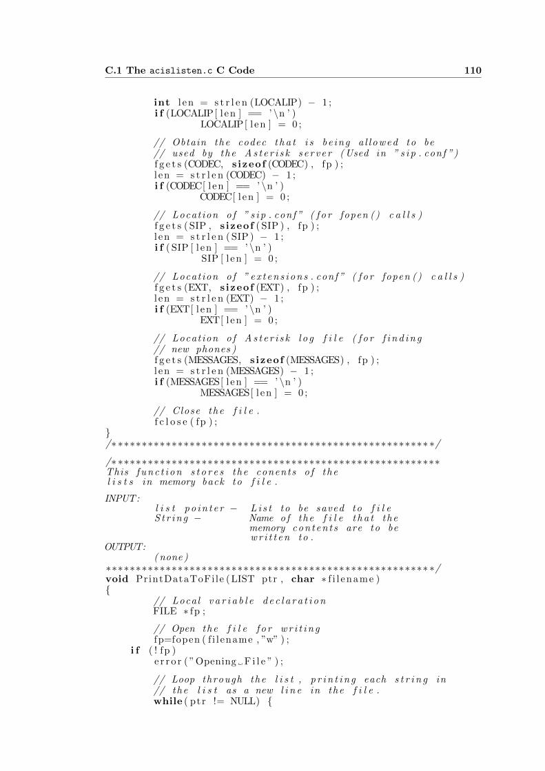
C.1 The acislisten.c C Code 110
int l en = s t r l e n (LOCALIP) − 1 ;i f (LOCALIP[ l en ] == ’ ∖n ’ )
LOCALIP[ l en ] = 0 ;
// Obtain the codec t h a t i s be ing a l l o w e d to be// used by the A s t e r i s k s e r v e r ( Used in ” s i p . conf ”)f g e t s (CODEC, s izeof (CODEC) , fp ) ;l en = s t r l e n (CODEC) − 1 ;i f (CODEC[ l en ] == ’ ∖n ’ )
CODEC[ l en ] = 0 ;
// Locat ion o f ” s i p . conf ” ( f o r fopen () c a l l s )f g e t s ( SIP , s izeof ( SIP ) , fp ) ;l en = s t r l e n ( SIP ) − 1 ;i f ( SIP [ l en ] == ’ ∖n ’ )
SIP [ l en ] = 0 ;
// Locat ion o f ” e x t e n s i o n s . conf ” ( f o r fopen () c a l l s )f g e t s (EXT, s izeof (EXT) , fp ) ;l en = s t r l e n (EXT) − 1 ;i f (EXT[ l en ] == ’ ∖n ’ )
EXT[ l en ] = 0 ;
// Locat ion o f A s t e r i s k l o g f i l e ( f o r f i n d i n g// new phones )f g e t s (MESSAGES, s izeof (MESSAGES) , fp ) ;l en = s t r l e n (MESSAGES) − 1 ;i f (MESSAGES[ l en ] == ’ ∖n ’ )
MESSAGES[ l en ] = 0 ;
// Close the f i l e .f c l o s e ( fp ) ;
}/∗ ∗∗∗∗∗∗∗∗∗∗∗∗∗∗∗∗∗∗∗∗∗∗∗∗∗∗∗∗∗∗∗∗∗∗∗∗∗∗∗∗∗∗∗∗∗∗∗∗∗∗∗∗ ∗/
/∗ ∗∗∗∗∗∗∗∗∗∗∗∗∗∗∗∗∗∗∗∗∗∗∗∗∗∗∗∗∗∗∗∗∗∗∗∗∗∗∗∗∗∗∗∗∗∗∗∗∗∗∗∗∗∗This f u n c t i o n s t o r e s the conents o f thel i s t s in memory back to f i l e .
INPUT:l i s t p o i n t e r − L i s t to be saved to f i l eS t r i n g − Name of the f i l e t h a t the
memory c o n t e n t s are to bew r i t t e n to .
OUTPUT:( none )
∗∗∗∗∗∗∗∗∗∗∗∗∗∗∗∗∗∗∗∗∗∗∗∗∗∗∗∗∗∗∗∗∗∗∗∗∗∗∗∗∗∗∗∗∗∗∗∗∗∗∗∗∗∗ ∗/void PrintDataToFile (LIST ptr , char ∗ f i l ename ){
// Local v a r i a b l e d e c l a r a t i o nFILE ∗ fp ;
// Open the f i l e f o r w r i t i n gfp=fopen ( f i l ename , ”w” ) ;
i f ( ! fp )e r r o r ( ”Opening F i l e ” ) ;
// Loop through the l i s t , p r i n t i n g each s t r i n g in// the l i s t as a new l i n e in the f i l e .while ( ptr != NULL) {

C.1 The acislisten.c C Code 111
f p r i n t f ( fp , ”%s ∖n” , ptr−>s t r ) ;ptr = ptr−>next ;
}// Close the f i l e .f c l o s e ( fp ) ;
}/∗ ∗∗∗∗∗∗∗∗∗∗∗∗∗∗∗∗∗∗∗∗∗∗∗∗∗∗∗∗∗∗∗∗∗∗∗∗∗∗∗∗∗∗∗∗∗∗∗∗∗∗∗∗ ∗/
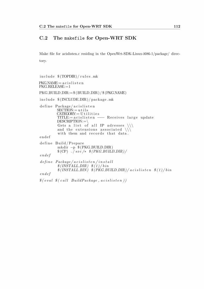
C.2 The makefile for Open-WRT SDK 112
C.2 The makefile for Open-WRT SDK
Make file for acislisten.c residing in the OpenWrt-SDK-Linux-i686-1/package/ direc-
tory.
i n c lude $ (TOPDIR)/ r u l e s .mk
PKG NAME:= a c i s l i s t e nPKG RELEASE:=1
PKG BUILD DIR:=$ (BUILD DIR)/ $ (PKG NAME)
inc lude $ (INCLUDE DIR)/ package .mk
d e f i n e Package/ a c i s l i s t e nSECTION:= u t i l sCATEGORY:= U t i l i t i e sTITLE:= a c i s l i s t e n −−− Rece ives l a r g e updateDESCRIPTION:=∖Gets a l i s t o f a l l IP a d r e s s e s ∖∖∖and the ex t en s i on s a s s o c i a t e d ∖∖∖with them and reco rd s that data .
endef
d e f i n e Build / Preparemkdir −p $ (PKG BUILD DIR)$ (CP) . / s r c /∗ $ (PKG BUILD DIR)/
endef
d e f i n e Package/ a c i s l i s t e n / i n s t a l l$ (INSTALL DIR) $ (1)/ b in$ (INSTALL BIN) $ (PKG BUILD DIR)/ a c i s l i s t e n $ (1)/ b in
endef
$ ( e v a l $ ( c a l l BuildPackage , a c i s l i s t e n ) )
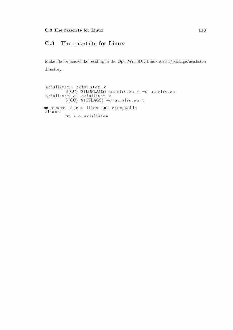
C.3 The makefile for Linux 113
C.3 The makefile for Linux
Make file for acissend.c residing in the OpenWrt-SDK-Linux-i686-1/package/acislisten
directory.
a c i s l i s t e n : a c i s l i s t e n . o$ (CC) $ (LDFLAGS) a c i s l i s t e n . o −o a c i s l i s t e n
a c i s l i s t e n . o : a c i s l i s t e n . c$ (CC) $ (CFLAGS) −c a c i s l i s t e n . c
# remove ob j e c t f i l e s and executab l ec l ean :
rm ∗ . o a c i s l i s t e n

C.4 The acissend.c C Code 114
C.4 The acissend.c C Code
/∗ ∗∗∗∗∗∗∗∗∗∗∗∗∗∗∗∗∗∗∗∗∗∗∗∗∗∗∗∗∗∗∗∗∗∗∗∗∗∗∗∗∗∗∗∗∗∗∗∗∗∗∗∗∗∗C CODE f o r a c i s l i s t e n ( A s t e r i s k C l i e n t Informat ionSharing − l i s t e n )
a c i s l i s t e n i s a program t h a t has been deve loped to wai te n d l e s s l y f o r data about remote A s t e r i s k s e r v e r s . Oncedata has been rece ived , t h i s data i s processed todetermine i f the in format ion i s new .
I f the data r e c e i v e d cont a in s in format ion about a newA s t e r i s k server , the data i s added to the l o c a lA s t e r i s k s e r v e r and the A s t e r i s k s e r v e r i s r e l o a d e dto en ab l e c a l l s to the remote A s t e r i s k s e r v e r .
This program i s w r i t t e n to s p e c i f i c a l l y f o r theWRT54GL ( ver 1 . 1 ) w i r e l e s s r o u t e r running Open−WRT( White Russian v0 . 9 ) Firmware .
Author : Adam JonesDate : October 2009∗∗∗∗∗∗∗∗∗∗∗∗∗∗∗∗∗∗∗∗∗∗∗∗∗∗∗∗∗∗∗∗∗∗∗∗∗∗∗∗∗∗∗∗∗∗∗∗∗∗∗∗∗∗ ∗/#include <sys / socket . h>#include <sys / types . h>#include <n e t i n e t / in . h>#include <netdb . h>#include <s t d i o . h>#include <s t r i n g . h>#include <s t d l i b . h>#include <uni s td . h>#include <errno . h>#include <arpa / i n e t . h>#include < l i m i t s . h>#include <s tdboo l . h>
/∗ ∗∗∗∗∗∗∗∗∗∗∗∗∗∗∗∗∗∗∗∗∗∗∗∗∗∗∗∗∗∗∗∗∗∗∗∗∗∗∗∗∗∗∗∗∗∗∗∗∗∗∗∗∗∗This s t r u c t u r e i s to ho ld v i r t u a l f i l e sin memory as w e l l as the e x t e n s i o n s t h a tare to be s t o r e d i n t o the f i l e s , ” s i p . conf ”and ” e x t e n s i o n s . conf ” .∗∗∗∗∗∗∗∗∗∗∗∗∗∗∗∗∗∗∗∗∗∗∗∗∗∗∗∗∗∗∗∗∗∗∗∗∗∗∗∗∗∗∗∗∗∗∗∗∗∗∗∗∗∗ ∗/struct l i s t{
char s t r [ 1 2 8 ] ;struct l i s t ∗next ;
} ;
typedef struct l i s t LST;typedef LST ∗LIST ;/∗ ∗∗∗∗∗∗∗∗∗∗∗∗∗∗∗∗∗∗∗∗∗∗∗∗∗∗∗∗∗∗∗∗∗∗∗∗∗∗∗∗∗∗∗∗∗∗∗∗∗∗∗∗ ∗/
// Function Proto typesLIST ReadFileToMem (char ∗ ) ;LIST SearchL i s t (LIST , char ∗ ) ;void D e l e t e L i s t (LIST ) ;void AddToList (LIST∗ , char ∗ ) ;void AddEXTDataLocal (LIST , char ∗ , char ∗ ) ;void AddSIPDataLocal (LIST , char ∗ , char ∗ ) ;void S e t L o ca l S e t t i ng s ( ) ;void WaitForInfo ( ) ;
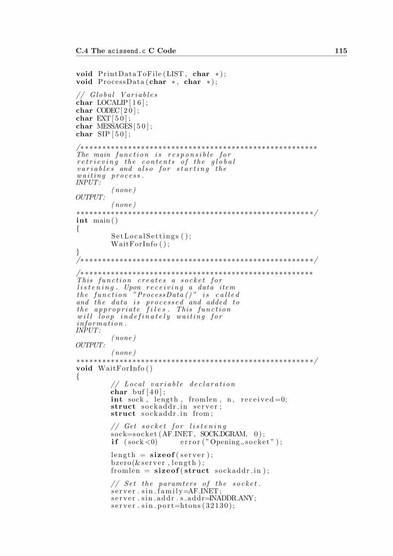
C.4 The acissend.c C Code 115
void PrintDataToFile (LIST , char ∗ ) ;void ProcessData (char ∗ , char ∗ ) ;
// Globa l V a r i a b l e schar LOCALIP [ 1 6 ] ;char CODEC[ 2 0 ] ;char EXT[ 5 0 ] ;char MESSAGES[ 5 0 ] ;char SIP [ 5 0 ] ;
/∗ ∗∗∗∗∗∗∗∗∗∗∗∗∗∗∗∗∗∗∗∗∗∗∗∗∗∗∗∗∗∗∗∗∗∗∗∗∗∗∗∗∗∗∗∗∗∗∗∗∗∗∗∗∗∗The main f u n c t i o n i s r e s p o n s i b l e f o rr e t r i e v i n g the c o n t e n t s o f the g l o b a lv a r i a b l e s and a l s o f o r s t a r t i n g thew a i t i n g pro ces s .INPUT:
( none )OUTPUT:
( none )∗∗∗∗∗∗∗∗∗∗∗∗∗∗∗∗∗∗∗∗∗∗∗∗∗∗∗∗∗∗∗∗∗∗∗∗∗∗∗∗∗∗∗∗∗∗∗∗∗∗∗∗∗∗ ∗/int main ( ){
S e t L o ca l S e t t i n g s ( ) ;WaitForInfo ( ) ;
}/∗ ∗∗∗∗∗∗∗∗∗∗∗∗∗∗∗∗∗∗∗∗∗∗∗∗∗∗∗∗∗∗∗∗∗∗∗∗∗∗∗∗∗∗∗∗∗∗∗∗∗∗∗∗ ∗/
/∗ ∗∗∗∗∗∗∗∗∗∗∗∗∗∗∗∗∗∗∗∗∗∗∗∗∗∗∗∗∗∗∗∗∗∗∗∗∗∗∗∗∗∗∗∗∗∗∗∗∗∗∗∗∗This f u n c t i o n c r e a t e s a s o c k e t f o rl i s t e n i n g . Upon r e c e i v i n g a data itemthe f u n c t i o n ” ProcessData ()” i s c a l l e dand the data i s processed and added tothe a p p r o p r i a t e f i l e s . This f u n c t i o nw i l l l oop i n d e f i n a t e l y w a i t i n g f o rin format ion .INPUT:
( none )OUTPUT:
( none )∗∗∗∗∗∗∗∗∗∗∗∗∗∗∗∗∗∗∗∗∗∗∗∗∗∗∗∗∗∗∗∗∗∗∗∗∗∗∗∗∗∗∗∗∗∗∗∗∗∗∗∗∗∗ ∗/void WaitForInfo ( ){
// Local v a r i a b l e d e c l a r a t i o nchar buf [ 4 0 ] ;int sock , length , fromlen , n , r e c e i v e d =0;struct sockaddr in s e r v e r ;struct sockaddr in from ;
// Get s o c k e t f o r l i s t e n i n gsock=socket (AF INET , SOCK DGRAM, 0 ) ;i f ( sock <0) e r r o r ( ”Opening socke t ” ) ;
l ength = s izeof ( s e r v e r ) ;bzero(&server , l ength ) ;f romlen = s izeof ( struct sockaddr in ) ;
// Set the paramters o f the s o c k e t .s e r v e r . s i n f a m i l y=AF INET ;s e r v e r . s i n addr . s addr=INADDR ANY;s e r v e r . s i n p o r t=htons (321 30 ) ;
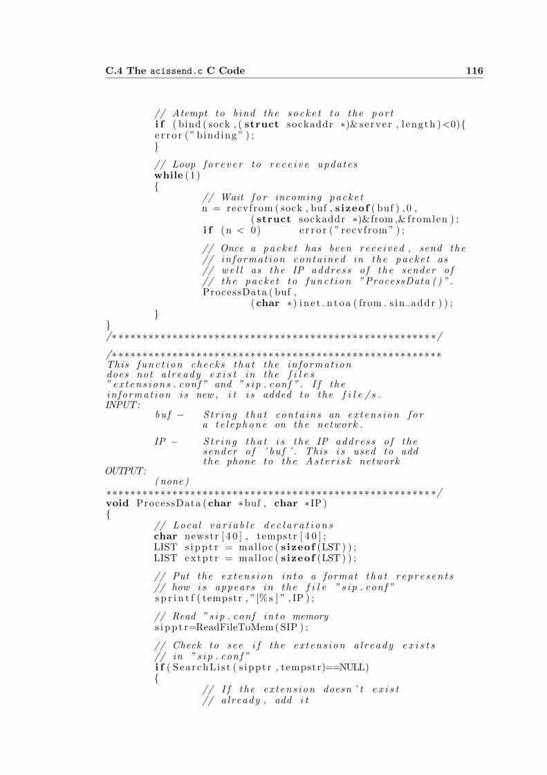
C.4 The acissend.c C Code 116
// Atempt to bind the s o c k e t to the por ti f ( bind ( sock , ( struct sockaddr ∗)& server , l ength )<0){e r r o r ( ” binding ” ) ;}
// Loop f o r e v e r to r e c e i v e updateswhile (1 ){
// Wait f o r incoming packe tn = recvfrom ( sock , buf , s izeof ( buf ) , 0 ,
( struct sockaddr ∗)&from ,& fromlen ) ;i f (n < 0) e r r o r ( ” recvfrom ” ) ;
// Once a packe t has been rece ived , send the// in format ion conta ined in the packe t as// w e l l as the IP address o f the sender o f// the packe t to f u n c t i o n ” ProcessData ( ) ” .ProcessData ( buf ,
(char ∗) i n e t n t o a ( from . s in addr ) ) ;}
}/∗ ∗∗∗∗∗∗∗∗∗∗∗∗∗∗∗∗∗∗∗∗∗∗∗∗∗∗∗∗∗∗∗∗∗∗∗∗∗∗∗∗∗∗∗∗∗∗∗∗∗∗∗∗ ∗/
/∗ ∗∗∗∗∗∗∗∗∗∗∗∗∗∗∗∗∗∗∗∗∗∗∗∗∗∗∗∗∗∗∗∗∗∗∗∗∗∗∗∗∗∗∗∗∗∗∗∗∗∗∗∗∗∗This f u n c t i o n checks t h a t the in format iondoes not a l r e a d y e x i s t in the f i l e s” e x t e n s i o n s . conf ” and ” s i p . conf ” . I f thein format ion i s new , i t i s added to the f i l e / s .INPUT:
bu f − S t r i n g t h a t c ont a ins an e x t e n s i o n f o ra t e l e p h o n e on the network .
IP − S t r i n g t h a t i s the IP address o f thesender o f ’ bu f ’ . This i s used to addthe phone to the A s t e r i s k network
OUTPUT:( none )
∗∗∗∗∗∗∗∗∗∗∗∗∗∗∗∗∗∗∗∗∗∗∗∗∗∗∗∗∗∗∗∗∗∗∗∗∗∗∗∗∗∗∗∗∗∗∗∗∗∗∗∗∗∗ ∗/void ProcessData (char ∗buf , char ∗IP ){
// Local v a r i a b l e d e c l a r a t i o n schar newstr [ 4 0 ] , tempstr [ 4 0 ] ;LIST s i p p t r = mal loc ( s izeof (LST ) ) ;LIST extpt r = mal loc ( s izeof (LST ) ) ;
// Put the e x t e n s i o n i n t o a format t h a t r e p r e s e n t s// how i s appears in the f i l e ” s i p . conf ”s p r i n t f ( tempstr , ”[%s ] ” , IP ) ;
// Read ” s i p . conf i n t o memorys i p p t r=ReadFileToMem ( SIP ) ;
// Check to see i f the e x t e n s i o n a l r e a d y e x i s t s// in ” s i p . conf ”i f ( SearchL i s t ( s ippt r , tempstr)==NULL){
// I f the e x t e n s i o n doesn ’ t e x i s t// a lready , add i t

C.4 The acissend.c C Code 117
AddSIPDataLocal ( s ippt r , IP , buf ) ;
// Save to updated ” s i p . conf ” back to d i s kPrintDataToFile ( s ippt r , SIP ) ;
// system command to t e l l a s t e r i s k// to r e l o a d ” s i p . conf ”system ( ” a s t e r i s k −rx ’ s i p r e l oad ’ ” ) ;
}// Read ” e x t e n s i o n s . conf ” i n t o memoryextpt r=ReadFileToMem (EXT) ;
// Put the e x t e n s i o n i n t o a format t h a t// r e p r e s e n t s how i s appears in the f i l e// ” e x t e n s i o n s . conf ”s p r i n t f ( tempstr , ”>%s , ” , buf ) ;
// Check to see i f the e x t e n s i o n a l r e a d y// e x i s t s in ” e x t e n s i o n s . conf ”i f ( SearchL i s t ( extptr , tempstr)==NULL){
// I f the e x t e n s i o n doesn ’ t e x i s t// a lready , add i tAddEXTDataLocal ( extptr , IP , buf ) ;
// Save to updated ” e x t e n s i o n s . conf ”// back to d i s kPrintDataToFile ( extptr , EXT) ;
// system command to t e l l a s t e r i s k to// r e l o a d ” e x t e n s i o n s . conf ”system ( ” a s t e r i s k −rx ’ ex t en s i on s r e l oad ’ ” ) ;
}// Free the memory t h a t h o l d s ” e x t e n s i o n s . conf ”// and ” s i p . conf ”D e l e t e L i s t ( s i p p t r ) ;D e l e t e L i s t ( extpt r ) ;
}/∗ ∗∗∗∗∗∗∗∗∗∗∗∗∗∗∗∗∗∗∗∗∗∗∗∗∗∗∗∗∗∗∗∗∗∗∗∗∗∗∗∗∗∗∗∗∗∗∗∗∗∗∗∗ ∗/
/∗ ∗∗∗∗∗∗∗∗∗∗∗∗∗∗∗∗∗∗∗∗∗∗∗∗∗∗∗∗∗∗∗∗∗∗∗∗∗∗∗∗∗∗∗∗∗∗∗∗∗∗∗∗∗∗This f u n c t i o n read a f i l e and s t o r e s i ti n t o memory .INPUT:
S t r i n g − co nta i ns the f i l ename to beread from .
OUTPUT:LIST p o i n t e r − co nta i ns the address to the
f i r s t e lement o f the f i l e( in memory)
∗∗∗∗∗∗∗∗∗∗∗∗∗∗∗∗∗∗∗∗∗∗∗∗∗∗∗∗∗∗∗∗∗∗∗∗∗∗∗∗∗∗∗∗∗∗∗∗∗∗∗∗∗∗ ∗/LIST ReadFileToMem (char ∗ fn ){
// Local v a r i a b l e d e c l a r a t i o n sFILE ∗ f i l e p t r ;LIST p = NULL;char l i n e [LINE MAX ] ;int l ength ;

C.4 The acissend.c C Code 118
// Open the f i l e f o r readingf i l e p t r=fopen ( fn , ” r ” ) ;
i f ( ! f i l e p t r ) { e r r o r ( ”Opening F i l e ” ) ; }
// Loop to g e t the c o n t e n t s o f the f i l e l i n e−by−l i n e// and s t o r e the c o n t e n t s i n t o a l i s twhile ( f g e t s ( l i n e , s izeof ( l i n e ) , f i l e p t r ) != NULL ){
// I f the l i n e ends wi th a new l i n e , change i t// to a n u l l t erminatorl ength = s t r l e n ( l i n e ) − 1 ;i f ( l i n e [ l ength ] == ’ ∖n ’ ) { l i n e [ l ength ] = 0 ;}
// Add the l i n e to the l i s tAddToList(&p , l i n e ) ;
}// Close the f i l ef c l o s e ( f i l e p t r ) ;
// Return the p o i n t e r to the s t a r t o f the l i s t .return p ;
}/∗ ∗∗∗∗∗∗∗∗∗∗∗∗∗∗∗∗∗∗∗∗∗∗∗∗∗∗∗∗∗∗∗∗∗∗∗∗∗∗∗∗∗∗∗∗∗∗∗∗∗∗∗∗ ∗/
/∗ ∗∗∗∗∗∗∗∗∗∗∗∗∗∗∗∗∗∗∗∗∗∗∗∗∗∗∗∗∗∗∗∗∗∗∗∗∗∗∗∗∗∗∗∗∗∗∗∗∗∗∗∗∗∗This f u n c t i o n s e a r c h e s f o r a matchbetween a l i s t and a s t r i n g and r e t u r n sthe matching element .INPUT:
LIST p o i n t e r − Contains a p o i n t e r to a l i s tt h a t i s to be searched f o r amatch .
s t r i n g − The s t r i n g t h a t i s to besearched f o r w i t h i n the l i s t .
OUTPUT:LIST p o i n t e r − Upon f i n d i n g the s t r i n g w i t h i n
the l i s t , the p o i n t e r to t h a te lement i s re turned . I f thes t r i n g i s not found , NULL i sre turned by the f u n c t i o n .
∗∗∗∗∗∗∗∗∗∗∗∗∗∗∗∗∗∗∗∗∗∗∗∗∗∗∗∗∗∗∗∗∗∗∗∗∗∗∗∗∗∗∗∗∗∗∗∗∗∗∗∗∗∗ ∗/LIST SearchL i s t (LIST ptr , char ∗ s e a r c h s t r ){
while ( ptr !=NULL){
i f ( s t r s t r ( ptr−>s t r , s e a r c h s t r ) )return ptr ;
ptr = ptr−>next ;}return NULL;
}/∗ ∗∗∗∗∗∗∗∗∗∗∗∗∗∗∗∗∗∗∗∗∗∗∗∗∗∗∗∗∗∗∗∗∗∗∗∗∗∗∗∗∗∗∗∗∗∗∗∗∗∗∗∗ ∗/
/∗ ∗∗∗∗∗∗∗∗∗∗∗∗∗∗∗∗∗∗∗∗∗∗∗∗∗∗∗∗∗∗∗∗∗∗∗∗∗∗∗∗∗∗∗∗∗∗∗∗∗∗∗∗∗∗This f u n c t i o n d e l t e s the c o n t e n t s o f thel i s t t h a t i s passed to i t from the p o i n to f the e lement t h a t i s passed to i t .INPUT:
LIST p o i n t e r − Contains a p o i n t e r to a l i s t
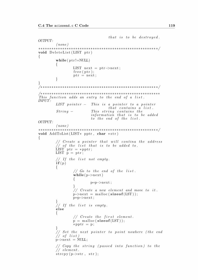
C.4 The acissend.c C Code 119
t h a t i s to be d e s t r o y e d .OUTPUT:
( none )∗∗∗∗∗∗∗∗∗∗∗∗∗∗∗∗∗∗∗∗∗∗∗∗∗∗∗∗∗∗∗∗∗∗∗∗∗∗∗∗∗∗∗∗∗∗∗∗∗∗∗∗∗∗ ∗/void D e l e t e L i s t (LIST ptr ){
while ( ptr !=NULL){
LIST next = ptr−>next ;f r e e ( ptr ) ;ptr = next ;
}}/∗ ∗∗∗∗∗∗∗∗∗∗∗∗∗∗∗∗∗∗∗∗∗∗∗∗∗∗∗∗∗∗∗∗∗∗∗∗∗∗∗∗∗∗∗∗∗∗∗∗∗∗∗∗ ∗/
/∗ ∗∗∗∗∗∗∗∗∗∗∗∗∗∗∗∗∗∗∗∗∗∗∗∗∗∗∗∗∗∗∗∗∗∗∗∗∗∗∗∗∗∗∗∗∗∗∗∗∗∗∗∗∗∗This f u n c t i o n adds an entry to the end o f a l i s t .INPUT:
LIST p o i n t e r − This i s a p o i n t e r to a p o i n t e rt h a t co nta ins a l i s t .
S t r i n g − This s t r i n g con ta i ns thein format ion t h a t i s to be addedto the end o f the l i s t .
OUTPUT:( none )
∗∗∗∗∗∗∗∗∗∗∗∗∗∗∗∗∗∗∗∗∗∗∗∗∗∗∗∗∗∗∗∗∗∗∗∗∗∗∗∗∗∗∗∗∗∗∗∗∗∗∗∗∗∗ ∗/void AddToList (LIST∗ pptr , char ∗ s t r ){
// Create a p o i n t e r t h a t w i l l cont ina the address// o f the l i s t t h a t i s to be added to .LIST ptr = ∗pptr ;LIST p = ptr ;
// I f the l i s t not empty .i f (p){
// Go to the end o f the l i s t .while (p−>next ){
p=p−>next ;}// Create a new element and move to i t .p−>next = mal loc ( s izeof (LST ) ) ;p=p−>next ;
}// I f the l i s t i s empty .else{
// Create the f i r s t e lement .p = mal loc ( s izeof (LST ) ) ;∗pptr = p ;
}// Set the next p o i n t e r to p o i n t nowhere ( the end// o f l i s t )p−>next = NULL;
// Copy the s t r i n g ( passed i n t o f u n c t i o n ) to the// element .s t r cpy (p−>s t r , s t r ) ;
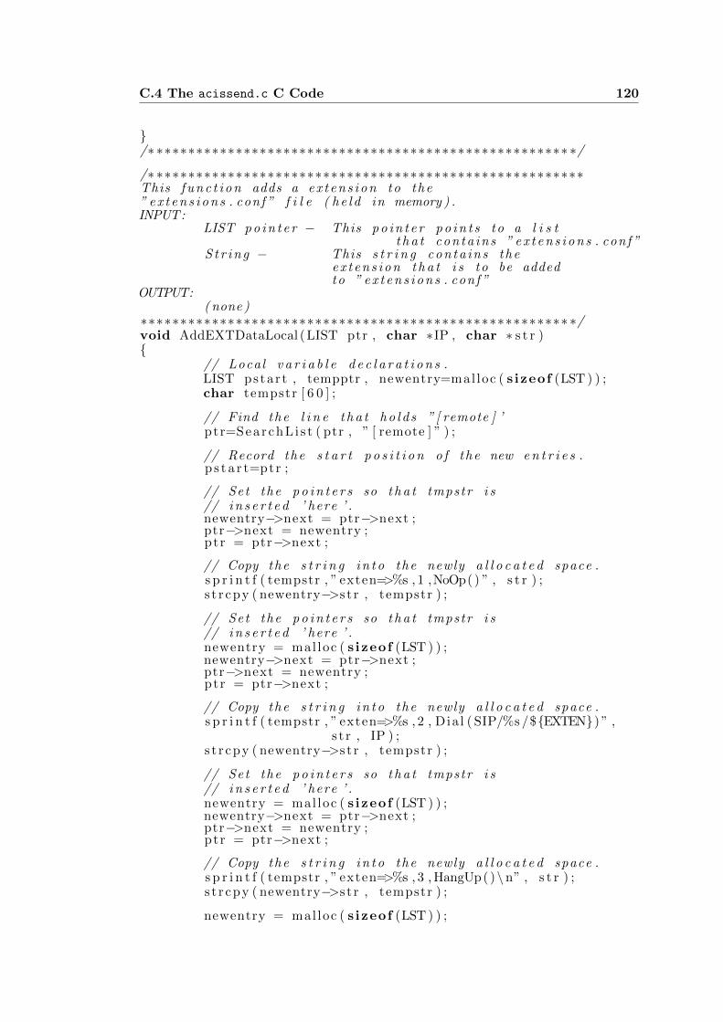
C.4 The acissend.c C Code 120
}/∗ ∗∗∗∗∗∗∗∗∗∗∗∗∗∗∗∗∗∗∗∗∗∗∗∗∗∗∗∗∗∗∗∗∗∗∗∗∗∗∗∗∗∗∗∗∗∗∗∗∗∗∗∗ ∗/
/∗ ∗∗∗∗∗∗∗∗∗∗∗∗∗∗∗∗∗∗∗∗∗∗∗∗∗∗∗∗∗∗∗∗∗∗∗∗∗∗∗∗∗∗∗∗∗∗∗∗∗∗∗∗∗∗This f u n c t i o n adds a e x t e n s i o n to the” e x t e n s i o n s . conf ” f i l e ( h e l d in memory ) .INPUT:
LIST p o i n t e r − This p o i n t e r p o i n t s to a l i s tt h a t co nta ins ” e x t e n s i o n s . conf ”
S t r i n g − This s t r i n g con ta i ns thee x t e n s i o n t h a t i s to be addedto ” e x t e n s i o n s . conf ”
OUTPUT:( none )
∗∗∗∗∗∗∗∗∗∗∗∗∗∗∗∗∗∗∗∗∗∗∗∗∗∗∗∗∗∗∗∗∗∗∗∗∗∗∗∗∗∗∗∗∗∗∗∗∗∗∗∗∗∗ ∗/void AddEXTDataLocal (LIST ptr , char ∗IP , char ∗ s t r ){
// Local v a r i a b l e d e c l a r a t i o n s .LIST pstart , tempptr , newentry=mal loc ( s izeof (LST ) ) ;char tempstr [ 6 0 ] ;
// Find the l i n e t h a t h o l d s ” [ remote ] ’ptr=SearchL i s t ( ptr , ” [ remote ] ” ) ;
// Record the s t a r t p o s i t i o n o f the new e n t r i e s .p s t a r t=ptr ;
// Set the p o i n t e r s so t h a t tmpstr i s// i n s e r t e d ’ here ’ .newentry−>next = ptr−>next ;ptr−>next = newentry ;ptr = ptr−>next ;
// Copy the s t r i n g i n t o the newly a l l o c a t e d space .s p r i n t f ( tempstr , ” exten=>%s , 1 ,NoOp( ) ” , s t r ) ;s t r cpy ( newentry−>s t r , tempstr ) ;
// Set the p o i n t e r s so t h a t tmpstr i s// i n s e r t e d ’ here ’ .newentry = mal loc ( s izeof (LST ) ) ;newentry−>next = ptr−>next ;ptr−>next = newentry ;ptr = ptr−>next ;
// Copy the s t r i n g i n t o the newly a l l o c a t e d space .s p r i n t f ( tempstr , ” exten=>%s , 2 , Dia l ( SIP/%s /${EXTEN}) ” ,
s t r , IP ) ;s t r cpy ( newentry−>s t r , tempstr ) ;
// Set the p o i n t e r s so t h a t tmpstr i s// i n s e r t e d ’ here ’ .newentry = mal loc ( s izeof (LST ) ) ;newentry−>next = ptr−>next ;ptr−>next = newentry ;ptr = ptr−>next ;
// Copy the s t r i n g i n t o the newly a l l o c a t e d space .s p r i n t f ( tempstr , ” exten=>%s , 3 , HangUp()∖n” , s t r ) ;s t r cpy ( newentry−>s t r , tempstr ) ;
newentry = mal loc ( s izeof (LST ) ) ;
C.4 The acissend.c C Code 121
// Find the l i n e t h a t h o l d s ” [ remote ] ’while ( ! s t r s t r ( ptr−>next−>s t r , ” [ phones ] ” ) ){
ptr=ptr−>next ;}
// Create a s t r i n g to t e s t f o r the A s t e r i s k// s e r v e r s presence .s p r i n t f ( tempstr , ”[% s incoming ] ” , IP ) ;// I f t h e r e i s not a l r e a d y an entry f o r t h i s// a s t e r i s k s e r v e r .i f ( SearchL i s t ( pstar t , tempstr)==NULL){
// Add in format ion ’ here ’ f o r the s e r v e r .tempptr = mal loc ( s izeof (LST ) ) ;tempptr−>next = ptr−>next ;s p r i n t f ( tempstr , ”[% s incoming ] ” , IP ) ;s t r cpy ( tempptr−>s t r , tempstr ) ;ptr−>next = tempptr ;ptr = ptr−>next ;
tempptr = mal loc ( s izeof (LST ) ) ;tempptr−>next = ptr−>next ;s p r i n t f ( tempstr , ” i n c lude=>i n t e r n a l ∖n” ) ;s t r cpy ( tempptr−>s t r , tempstr ) ;ptr−>next = tempptr ;ptr = ptr−>next ;
}}/∗ ∗∗∗∗∗∗∗∗∗∗∗∗∗∗∗∗∗∗∗∗∗∗∗∗∗∗∗∗∗∗∗∗∗∗∗∗∗∗∗∗∗∗∗∗∗∗∗∗∗∗∗∗ ∗/
/∗ ∗∗∗∗∗∗∗∗∗∗∗∗∗∗∗∗∗∗∗∗∗∗∗∗∗∗∗∗∗∗∗∗∗∗∗∗∗∗∗∗∗∗∗∗∗∗∗∗∗∗∗∗∗∗This f u n c t i o n adds a e x t e n s i o n to the ” s i p . conf ”f i l e ( h e l d in memory ) .
INPUT:LIST p o i n t e r − This p o i n t e r p o i n t s to a l i s t
t h a t co nta ins ” s i p . conf ”S t r i n g − This s t r i n g con ta i ns the
e x t e n s i o n t h a t i s to be addedto ” s i p . conf ”
OUTPUT:( none )
∗∗∗∗∗∗∗∗∗∗∗∗∗∗∗∗∗∗∗∗∗∗∗∗∗∗∗∗∗∗∗∗∗∗∗∗∗∗∗∗∗∗∗∗∗∗∗∗∗∗∗∗∗∗ ∗/void AddSIPDataLocal (LIST ptr , char ∗IP , char ∗ s t r ){
// Local v a r i a b l e d e c l a r a t i o n s .char tempstr [ 6 0 ] ;LIST newentry , s t a r t p t r=ptr ;bool a l r e ad yE x i s t s=f a l s e ;
// Find the p o s i t i o n o f r e g i s t e rwhile ( ptr=SearchL i s t ( ptr , ” r e g i s t e r ” ) ){
// I f the IP address i s r e g i s t e r e d .i f ( s t r s t r ( ptr−>s t r , IP ) ){
// Record t h a t the r e g i s t r a t i o n has a l r e a d y// been entereda l r e ad yE x i s t s=true ;
C.4 The acissend.c C Code 122
}// Move to the next l i s t item .ptr=ptr−>next ;
}// I f t h e r e i s no r e g i s t r a t i o n in format ion in// the f i l e .i f ( ! a l r e ad yE x i s t s ){
// Add r e g i s t r a t i o n d e t a i l s .newentry = mal loc ( s izeof (LST ) ) ;s p r i n t f ( tempstr , ” r e g i s t e r=>%s : welcome@%s/%s ” ,
LOCALIP, IP , IP ) ;
s t r cpy ( newentry−>s t r , tempstr ) ;newentry−>next = ptr−>next ;ptr−>next = newentry ;
}// Add e n t r i e s to the end o f the f i l e .s p r i n t f ( tempstr , ”∖n[%s ] ” , IP ) ;AddToList(& s t a r t p t r , tempstr ) ;s p r i n t f ( tempstr , ” type=f r i e n d ” ) ;AddToList(& s t a r t p t r , tempstr ) ;s p r i n t f ( tempstr , ” s e c r e t=welcome” ) ;AddToList(& s t a r t p t r , tempstr ) ;s p r i n t f ( tempstr , ” context=%s incoming ” , IP ) ;AddToList(& s t a r t p t r , tempstr ) ;s p r i n t f ( tempstr , ” host=dynamic” ) ;AddToList(& s t a r t p t r , tempstr ) ;s p r i n t f ( tempstr , ” d i s a l l o w=a l l ” ) ;AddToList(& s t a r t p t r , tempstr ) ;s p r i n t f ( tempstr , ” a l low=%s ” ,CODEC) ;AddToList(& s t a r t p t r , tempstr ) ;
}/∗ ∗∗∗∗∗∗∗∗∗∗∗∗∗∗∗∗∗∗∗∗∗∗∗∗∗∗∗∗∗∗∗∗∗∗∗∗∗∗∗∗∗∗∗∗∗∗∗∗∗∗∗∗ ∗/
/∗ ∗∗∗∗∗∗∗∗∗∗∗∗∗∗∗∗∗∗∗∗∗∗∗∗∗∗∗∗∗∗∗∗∗∗∗∗∗∗∗∗∗∗∗∗∗∗∗∗∗∗∗∗∗∗This f u n c t i o n l o a d s g l o b a l v a r i a b l e sfrom a c o n f i g u r a t i o n f i l e t h a t i ss t o r e d in the r o u t e r in the d i r e c t o r y / b in /INPUT:
( none )OUTPUT:
( none )∗∗∗∗∗∗∗∗∗∗∗∗∗∗∗∗∗∗∗∗∗∗∗∗∗∗∗∗∗∗∗∗∗∗∗∗∗∗∗∗∗∗∗∗∗∗∗∗∗∗∗∗∗∗ ∗/void S e t L o ca l S e t t i n g s ( ){
// Local v a r i a b l e d e c l a r a t i o n sFILE ∗ fp ;
// Open the f i l e f o r readingfp=fopen ( ”/ bin /LOCALIP.ROUTER” , ” r ” ) ;
i f ( ! fp )e r r o r ( ”Opening F i l e ” ) ;
// Obtain the IP address o f the w i r e l e s s i n t e r f a c e// o f the r o u t e r ( used f o r unique name f o r// A s t e r i s k s e r v e r ) .f g e t s (LOCALIP, s izeof (LOCALIP) , fp ) ;

C.4 The acissend.c C Code 123
int l en = s t r l e n (LOCALIP) − 1 ;i f (LOCALIP[ l en ] == ’ ∖n ’ )
LOCALIP[ l en ] = 0 ;
// Obtain the codec t h a t i s be ing a l l o w e d to be// used by the A s t e r i s k s e r v e r ( Used in ” s i p . conf ”)f g e t s (CODEC, s izeof (CODEC) , fp ) ;l en = s t r l e n (CODEC) − 1 ;i f (CODEC[ l en ] == ’ ∖n ’ )
CODEC[ l en ] = 0 ;
// Locat ion o f ” s i p . conf ” ( f o r fopen () c a l l s )f g e t s ( SIP , s izeof ( SIP ) , fp ) ;l en = s t r l e n ( SIP ) − 1 ;i f ( SIP [ l en ] == ’ ∖n ’ )
SIP [ l en ] = 0 ;
// Locat ion o f ” e x t e n s i o n s . conf ” ( f o r fopen () c a l l s )f g e t s (EXT, s izeof (EXT) , fp ) ;l en = s t r l e n (EXT) − 1 ;i f (EXT[ l en ] == ’ ∖n ’ )
EXT[ l en ] = 0 ;
// Locat ion o f A s t e r i s k l o g f i l e ( f o r f i n d i n g// new phones )f g e t s (MESSAGES, s izeof (MESSAGES) , fp ) ;l en = s t r l e n (MESSAGES) − 1 ;i f (MESSAGES[ l en ] == ’ ∖n ’ )
MESSAGES[ l en ] = 0 ;
// Close the f i l e .f c l o s e ( fp ) ;
}/∗ ∗∗∗∗∗∗∗∗∗∗∗∗∗∗∗∗∗∗∗∗∗∗∗∗∗∗∗∗∗∗∗∗∗∗∗∗∗∗∗∗∗∗∗∗∗∗∗∗∗∗∗∗ ∗/
/∗ ∗∗∗∗∗∗∗∗∗∗∗∗∗∗∗∗∗∗∗∗∗∗∗∗∗∗∗∗∗∗∗∗∗∗∗∗∗∗∗∗∗∗∗∗∗∗∗∗∗∗∗∗∗∗This f u n c t i o n s t o r e s the conents o f thel i s t s in memory back to f i l e .
INPUT:l i s t p o i n t e r − L i s t to be saved to f i l eS t r i n g − Name of the f i l e t h a t the
memory c o n t e n t s are to bew r i t t e n to .
OUTPUT:( none )
∗∗∗∗∗∗∗∗∗∗∗∗∗∗∗∗∗∗∗∗∗∗∗∗∗∗∗∗∗∗∗∗∗∗∗∗∗∗∗∗∗∗∗∗∗∗∗∗∗∗∗∗∗∗ ∗/void PrintDataToFile (LIST ptr , char ∗ f i l ename ){
// Local v a r i a b l e d e c l a r a t i o nFILE ∗ fp ;
// Open the f i l e f o r w r i t i n gfp=fopen ( f i l ename , ”w” ) ;
i f ( ! fp )e r r o r ( ”Opening F i l e ” ) ;
// Loop through the l i s t , p r i n t i n g each s t r i n g in// the l i s t as a new l i n e in the f i l e .while ( ptr != NULL) {

C.4 The acissend.c C Code 124
f p r i n t f ( fp , ”%s ∖n” , ptr−>s t r ) ;ptr = ptr−>next ;
}// Close the f i l e .f c l o s e ( fp ) ;
}/∗ ∗∗∗∗∗∗∗∗∗∗∗∗∗∗∗∗∗∗∗∗∗∗∗∗∗∗∗∗∗∗∗∗∗∗∗∗∗∗∗∗∗∗∗∗∗∗∗∗∗∗∗∗ ∗/
C.5 The makefile for Open-WRT SDK 125
C.5 The makefile for Open-WRT SDK
Make file for acissend.c residing in the OpenWrt-SDK-Linux-i686-1/package/ directory.
i n c lude $ (TOPDIR)/ r u l e s .mk
PKG NAME:= ac i s s endPKG RELEASE:=1
PKG BUILD DIR:=$ (BUILD DIR)/ $ (PKG NAME)
inc lude $ (INCLUDE DIR)/ package .mk
d e f i n e Package/ ac i s s endSECTION:= u t i l sCATEGORY:= U t i l i t i e sTITLE:= ac i s s end −−− Rece ives l a r g e updateDESCRIPTION:=∖Gets a l i s t o f a l l IP a d r e s s e s ∖∖∖and the ex t en s i on s a s s o c i a t e d ∖∖∖with them and reco rd s that data .
endef
d e f i n e Build / Preparemkdir −p $ (PKG BUILD DIR)$ (CP) . / s r c /∗ $ (PKG BUILD DIR)/
endef
d e f i n e Package/ a c i s s e n d / i n s t a l l$ (INSTALL DIR) $ (1)/ b in$ (INSTALL BIN) $ (PKG BUILD DIR)/ a c i s s e n d $ (1)/ b in
endef
$ ( e v a l $ ( c a l l BuildPackage , a c i s s e n d ))
C.6 The makefile for Linux 126
C.6 The makefile for Linux
Make file for acissend.c residing in the OpenWrt-SDK-Linux-i686-1/package/acissend
directory.
a c i s s end : a c i s s end . o$ (CC) $ (LDFLAGS) ac i s s end . o −o ac i s s end
ac i s s end . o : a c i s s end . c$ (CC) $ (CFLAGS) −c ac i s s end . c
# remove ob j e c t f i l e s and executab l ec l ean :
rm ∗ . o a c i s s end