UNIT -1 COMPUTER INTEGRATED … -1 COMPUTER INTEGRATED MANUFACTURING SYSTEMS 1. INTRODUCTION...
29
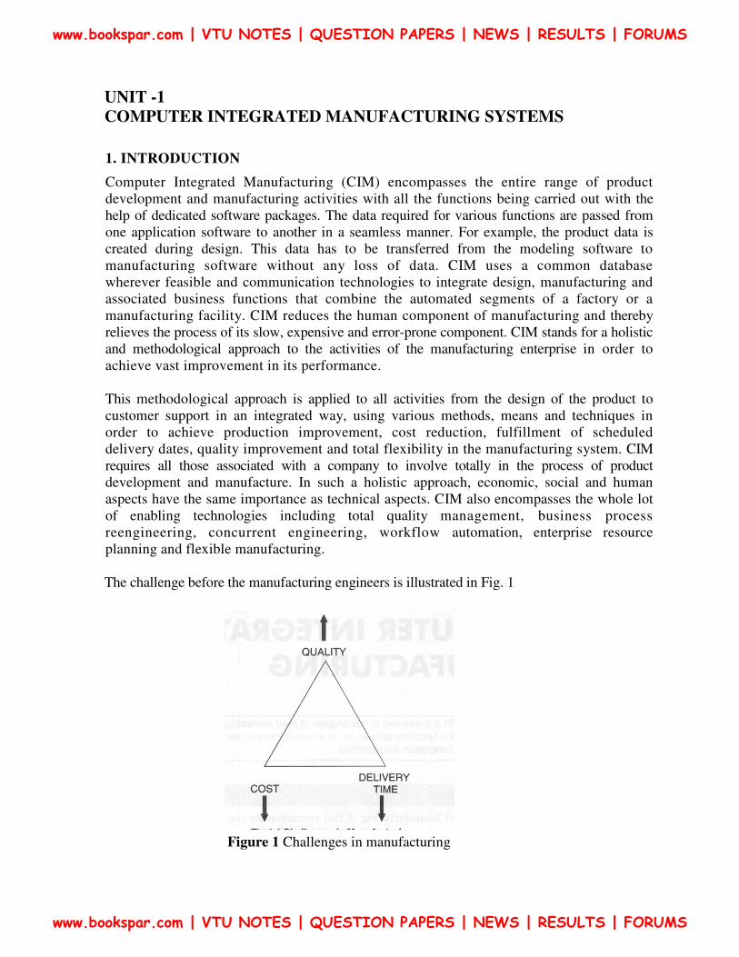
UNIT -1 COMPUTER INTEGRATED MANUFACTURING SYSTEMS 1. INTRODUCTION Computer Integrated Manufacturing (CIM) encompasses the entire range of product development and manufacturing activities with all the functions being carried out with the help of dedicated software packages. The data required for various functions are passed from one application software to another in a seamless manner. For example, the product data is created during design. This data has to be transferred from the modeling software to manufacturing software without any loss of data. CIM uses a common database wherever feasible and communication technologies to integrate design, manufacturing and associated business functions that combine the automated segments of a factory or a manufacturing facility. CIM reduces the human component of manufacturing and thereby relieves the process of its slow, expensive and error-prone component. CIM stands for a holistic and methodological approach to the activities of the manufacturing enterprise in order to achieve vast improvement in its performance. This methodological approach is applied to all activities from the design of the product to customer support in an integrated way, using various methods, means and techniques in order to achieve production improvement, cost reduction, fulfillment of scheduled delivery dates, quality improvement and total flexibility in the manufacturing system. CIM requires all those associated with a company to involve totally in the process of product development and manufacture. In such a holistic approach, economic, social and human aspects have the same importance as technical aspects. CIM also encompasses the whole lot of enabling technologies including total quality management, business process reengineering, concurrent engineering, workflow automation, enterprise resource planning and flexible manufacturing. The challenge before the manufacturing engineers is illustrated in Fig. 1 Figure 1 Challenges in manufacturing www.bookspar.com | VTU NOTES | QUESTION PAPERS | NEWS | RESULTS | FORUMS www.bookspar.com | VTU NOTES | QUESTION PAPERS | NEWS | RESULTS | FORUMS
Transcript of UNIT -1 COMPUTER INTEGRATED … -1 COMPUTER INTEGRATED MANUFACTURING SYSTEMS 1. INTRODUCTION...
UNIT -1
COMPUTER INTEGRATED MANUFACTURING SYSTEMS
1. INTRODUCTION
Computer Integrated Manufacturing (CIM) encompasses the entire range of product
development and manufacturing activities with all the functions being carried out with the
help of dedicated software packages. The data required for various functions are passed from
one application software to another in a seamless manner. For example, the product data is
created during design. This data has to be transferred from the modeling software to
manufacturing software without any loss of data. CIM uses a common database
wherever feasible and communication technologies to integrate design, manufacturing and
associated business functions that combine the automated segments of a factory or a
manufacturing facility. CIM reduces the human component of manufacturing and thereby
relieves the process of its slow, expensive and error-prone component. CIM stands for a holistic
and methodological approach to the activities of the manufacturing enterprise in order to
achieve vast improvement in its performance.
This methodological approach is applied to all activities from the design of the product to
customer support in an integrated way, using various methods, means and techniques in
order to achieve production improvement, cost reduction, fulfillment of scheduled
delivery dates, quality improvement and total flexibility in the manufacturing system. CIM
requires all those associated with a company to involve totally in the process of product
development and manufacture. In such a holistic approach, economic, social and human
aspects have the same importance as technical aspects. CIM also encompasses the whole lot
of enabling technologies including total quality management, business process
reengineering, concurrent engineering, workflow automation, enterprise resource
planning and flexible manufacturing.
The challenge before the manufacturing engineers is illustrated in Fig. 1
Figure 1 Challenges in manufacturing
www.bookspar.com | VTU NOTES | QUESTION PAPERS | NEWS | RESULTS | FORUMS
www.bookspar.com | VTU NOTES | QUESTION PAPERS | NEWS | RESULTS | FORUMS

Manufacturing industries strive to reduce the cost of the product continuously to remain competitive
in the face of global competition. In addition, there is the need to improve the quality and
performance levels on a continuing basis. Another important requirement is on time delivery. In
the context of global outsourcing and long supply chains cutting across several international
borders, the task of continuously reducing delivery times is really an arduous task. CIM has
several software tools to address the above needs.
Manufacturing engineers are required to achieve the following objectives to be competitive
in a global context.
• Reduction in inventory
• Lower the cost of the product
• Reduce waste
• Improve quality
• Increase flexibility in manufacturing to achieve immediate and rapid response
to:
• Product changes
• Production changes
• Process change
• Equipment change
• Change of personnel
CIM technology is an enabling technology to meet the above challenges to the
manufacturing.
2. EVOLUTION OF COMPUTER INTEGRATED MANUFACTURING
Computer Integrated Manufacturing (CIM) is considered a natural evolution of the
technology of CAD/CAM which by itself evolved by the integration of CAD and CAM.
Massachusetts Institute of Technology (MIT, USA) is credited with pioneering the
development in both CAD and CAM. The need to meet the design and manufacturing
requirements of aerospace industries after the Second World War necessitated the
development these technologies. The manufacturing technology available during late 40's and
early 50's could not meet the design and manufacturing challenges arising out of the need to
develop sophisticated aircraft and satellite launch vehicles. This prompted the US Air Force to
approach MIT to develop suitable control systems, drives and programming techniques for
machine tools using electronic control.
www.bookspar.com | VTU NOTES | QUESTION PAPERS | NEWS | RESULTS | FORUMS
www.bookspar.com | VTU NOTES | QUESTION PAPERS | NEWS | RESULTS | FORUMS

The first major innovation in machine control is the Numerical Control (NC),
demonstrated at MIT in 1952. Early Numerical Control Systems were all basically hardwired
systems, since these were built with discrete systems or with later first generation integrated
chips. Early NC machines used paper tape as an input medium. Every NC machine was
fitted with a tape reader to read paper tape and transfer the program to the memory of the
machine tool block by block. Mainframe computers were used to control a group of NC
machines by mid 60's. This arrangement was then called Direct Numerical Control (DNC) as
the computer bypassed the tape reader to transfer the program data to the machine
controller. By late 60's mini computers were being commonly used to control NC machines. At
this stage NC became truly soft wired with the facilities of mass program storage, offline
editing and software logic control and processing. This development is called Computer
Numerical Control (CNC). Since 70's, numerical controllers are being designed around
microprocessors, resulting in compact CNC systems. A further development to this
technology is the distributed numerical control (also called DNC) in which processing of
NC program is carried out in different computers operating at different hierarchical levels -
typically from mainframe host computers to plant computers to the machine controller.
Today the CNC systems are built around powerful 32 bit and 64 bit microprocessors. PC
based systems are also becoming increasingly popular.
Manufacturing engineers also started using computers for such tasks like inventory
control, demand forecasting, production planning and control etc. CNC technology was
adapted in the development of co-ordinate measuring machine's (CMMs) which automated
inspection. Robots were introduced to automate several tasks like machine loading,
materials handling, welding, painting and assembly. All these developments led to the
evolution of flexible manufacturing cells and flexible manufacturing systems in late 70's.
Evolution of Computer Aided Design (CAD), on the other hand was to cater to the
geometric modeling needs of automobile and aeronautical industries. The developments in
computers, design workstations, graphic cards, display devices and graphic input and
output devices during the last ten years have been phenomenal. This coupled with the
development of operating system with graphic user interfaces and powerful interactive (user
friendly) software packages for modeling, drafting, analysis and optimization provides
the necessary tools to automate the design process.
CAD in fact owes its development to the APT language project at MIT in early 50's.
Several clones of APT were introduced in 80's to automatically develop NC codes from the
geometric model of the component. Now, one can model, draft, analyze, simulate, modify,
optimize and create the NC code to manufacture a component and simulate the machining
operation sitting at a computer workstation.
If we review the manufacturing scenario during 80's we will find that the
manufacturing is characterized by a few islands of automation. In the case of design, the
task is well automated. In the case of manufacture, CNC machines, DNC systems, FMC,
FMS etc provide tightly controlled automation systems. Similarly computer control has been
implemented in several areas like manufacturing resource planning, accounting, sales,
marketing and purchase. Yet the full potential of computerization could not be obtained
www.bookspar.com | VTU NOTES | QUESTION PAPERS | NEWS | RESULTS | FORUMS
www.bookspar.com | VTU NOTES | QUESTION PAPERS | NEWS | RESULTS | FORUMS

unless all the segments of manufacturing are integrated, permitting the transfer of data
across various functional modules. This realization led to the concept of computer integrated
manufacturing. Thus the implementation of CIM required the development of whole lot
of computer technologies related to hardware and software.
3. CIM HARDWARE AND CIM SOFTWARE
CIM Hardware comprises the following:
i. Manufacturing equipment such as CNC machines or computerized work centers,
robotic work cells, DNC/FMS systems, work handling and tool handling devices,
storage devices, sensors, shop floor data collection devices, inspection machines etc.
ii. Computers, controllers, CAD/CAM systems, workstations / terminals, data entry
terminals, bar code readers, RFID tags, printers, plotters and other peripheral
devices, modems, cables, connectors etc.,
CIM software comprises computer programmes to carry out the following functions:
• Management Information System
• Sales
• Marketing
• Finance
• Database Management
• Modeling and Design
• Analysis
• Simulation
• Communications
• Monitoring
• Production Control
• Manufacturing Area Control
• Job Tracking
• Inventory Control
• Shop Floor Data Collection
• Order Entry
• Materials Handling
• Device Drivers
• Process Planning
• Manufacturing Facilities Planning
• Work Flow Automation
• Business Process Engineering
• Network Management
• Quality Management
www.bookspar.com | VTU NOTES | QUESTION PAPERS | NEWS | RESULTS | FORUMS
www.bookspar.com | VTU NOTES | QUESTION PAPERS | NEWS | RESULTS | FORUMS

4. NATURE AND ROLE OF THE ELEMENTS OF CIM SYSTEM
Nine major elements of a CIM system are in Figure 2 they are,
• Marketing
• Product Design
• Planning
• Purchase
• Manufacturing Engineering
• Factory Automation Hardware
• Warehousing
• Logistics and Supply Chain Management
• Finance
• Information Management
i. Marketing: The need for a product is identified by the marketing division. The
specifications of the product, the projection of manufacturing quantities and the strategy
for marketing the product are also decided by the marketing department. Marketing also
works out the manufacturing costs to assess the economic viability of the product.
ii. Product Design: The design department of the company establishes the initial database
for production of a proposed product. In a CIM system this is accomplished through
activities such as geometric modeling and computer aided design while considering the
product requirements and concepts generated by the creativity of the design engineer.
Configuration management is an important activity in many designs. Complex designs
Figure 2 Major elements of CIM systems
www.bookspar.com | VTU NOTES | QUESTION PAPERS | NEWS | RESULTS | FORUMS
www.bookspar.com | VTU NOTES | QUESTION PAPERS | NEWS | RESULTS | FORUMS

are usually carried out by several teams working simultaneously, located often in
different parts of the world. The design process is constrained by the costs that will be
incurred in actual production and by the capabilities of the available production
equipment and processes. The design process creates the database required to
manufacture the part.
iii. Planning: The planning department takes the database established by the design
department and enriches it with production data and information to produce a plan
for the production of the product. Planning involves several subsystems dealing with
materials, facility, process, tools, manpower, capacity, scheduling, outsourcing,
assembly, inspection, logistics etc. In a CIM system, this planning process should be
constrained by the production costs and by the production equipment and process
capability, in order to generate an optimized plan.
iv. Purchase: The purchase departments is responsible for placing the purchase orders
and follow up, ensure quality in the production process of the vendor, receive the
items, arrange for inspection and supply the items to the stores or arrange timely
delivery depending on the production schedule for eventual supply to manufacture and
assembly.
v. Manufacturing Engineering: Manufacturing Engineering is the activity of carrying out the
production of the product, involving further enrichment of the database with
performance data and information about the production equipment and processes. In
CIM, this requires activities like CNC programming, simulation and computer aided
scheduling of the production activity. This should include online dynamic scheduling
and control based on the real time performance of the equipment and processes to
assure continuous production activity. Often, the need to meet fluctuating market
demand requires the manufacturing system flexible and agile.
vi. Factory Automation Hardware: Factory automation equipment further enriches the
database with equipment and process data, resident either in the operator or the
equipment to carry out the production process. In CIM system this consists of
computer controlled process machinery such as CNC machine tools, flexible
manufacturing systems (FMS), Computer controlled robots, material handling systems,
computer controlled assembly systems, flexibly automated inspection systems and so on.
vii. Warehousing: Warehousing is the function involving storage and retrieval of raw
materials, components, finished goods as well as shipment of items. In today's complex
outsourcing scenario and the need for just-in-time supply of components and
subsystems, logistics and supply chain management assume great importance.
viii. Finance: Finance deals with the resources pertaining to money. Planning of
investment, working capital, and cash flow control, realization of receipts,
accounting and allocation of funds are the major tasks of the finance departments.
www.bookspar.com | VTU NOTES | QUESTION PAPERS | NEWS | RESULTS | FORUMS
www.bookspar.com | VTU NOTES | QUESTION PAPERS | NEWS | RESULTS | FORUMS

ix. Information Management: Information Management is perhaps one of the crucial tasks in
CIM. This involves master production scheduling, database management, communication,
manufacturing systems integration and management information systems.
Definition of CIM
Joel Goldhar, Dean, Illinois Institute of Technology gives CIM as a computer system in which
the peripherals are robots, machine tools and other processing equipment.
Dan Appleton, President, DACOM, Inc. defines CIM is a management philosophy, not a turnkey
product.
Jack Conaway, CIM Marketing manager, DEC, defines CIM is nothing but a data management
and networking problem.
The computer and automated systems association of the society of Manufacturing Engineers
(CASA/SEM) defines CIM is the integration of total manufacturing enterprise by using
integrated systems and data communication coupled with new managerial philosophies that
improve organizational and personnel efficiency.
CIM is recognized as Islands of Automation. They are
1. CAD/CAM/CAE/GT
2. Manufacturing Planning and Control.
3. Factory Automation
4. General Business Management
CASA/SME’s CIM Wheel is as shown in figure 4
Figure 4 CASA/SME’s CIM Wheel
www.bookspar.com | VTU NOTES | QUESTION PAPERS | NEWS | RESULTS | FORUMS
www.bookspar.com | VTU NOTES | QUESTION PAPERS | NEWS | RESULTS | FORUMS

Conceptual model of manufacturing
The computer has had and continues to have a dramatic impact on the development of
production automation technologies. Nearly all modern production systems are imple-
mented today using computer systems. The term computer integrated manufacturing
(CIM) has been coined to denote the pervasive use of computers to design the products,
plan the production, control the operations, and perform the various business related
functions needed in a manufacturing firm. CAD/CAM (computer-aided design and com-
puter-aided manufacturing) is another term that is used almost synonymously with CIM.
Let us attempt to define the relationship between automation and CIM by developing a
conceptual model of manufacturing. In a manufacturing firm, the physical activities
related to production that take place in the factory can be distinguished from the infor-
mation-processing activities, such as product design and production planning, that usually
occur in an office environment. The physical activities include all of the manufacturing
processing, assembly, material handling, and inspections that are performed on the prod-
uct. These operations come in direct contact with the product during manufacture. They
touch the product. The relationship between the physical activities and the information-
processing activities in our model is depicted in Figure 5. Raw materials flow in one end
of the factory and finished products flow out the other end. The physical activities
(processing, handling, etc.) take place inside the factory. The information-processing
functions form a ring that surrounds the factory, providing the data and knowledge required
to produce the product successfully. These information-processing functions include (1)
certain business activities (e.g., marketing and sales, order entry, customer billing, etc.),
(2) product design, (3) manufacturing planning, and (4) manufacturing control. These
four functions form a cycle of events that must accompany the physical production
activities but which do not directly touch the product.
Now consider the difference between automation and CIM. Automation is concerned with
the physical activities in manufacturing. Automated production systems are designed to
accomplish the processing, assembly, material handling, and inspecting activities with little
or no human participation. By comparison, computer integrated manufacturing is
(figure 5)
www.bookspar.com | VTU NOTES | QUESTION PAPERS | NEWS | RESULTS | FORUMS
www.bookspar.com | VTU NOTES | QUESTION PAPERS | NEWS | RESULTS | FORUMS

In the figure 5 Model of manufacturing, showing (a] the factory as a processing
pipeline where the physical manufacturing activities are performed, and (b) the
information-processing activities that support manufacturing as a ring that surrounds
the factory concerned more with the information-processing functions that are
required to support the production operations. CIM involves the use of computer
systems to perform the four types of information-processing functions. Just as
automation deals with the physical activities, CIM deals with automating the
information-processing activities in manufacturing.
AUTOMATION DEFINED
Automation is a technology concerned with the application of mechanical, electronic, and
computer-based systems to operate and control production. This technology includes:
� Automatic machine tools to process parts
� Automatic assembly machines
� Industrial robots
� Automatic material handling and storage systems
� Automatic inspection systems for quality control
� Feedback control and computer process control
� Computer systems for planning, data collection, and decision making
to support manufacturing activities
TYPES OF AUTOMATION
Automated production systems are classified into three basic types:
1. Fixed automation
2. Programmable automation
3. Flexible automation
Fixed automation
Fixed automation is a system in which the sequence of processing (or assembly)
operations is fixed by the equipment configuration. The operations in the sequence
are usually simple. It is the integration and coordination of many such operations into
one piece of equipment that makes the system complex. The typical features of fixed
automation are:
� High initial investment for custom-engineered equipment
� High production rates
� Relatively inflexible in accommodating product changes
www.bookspar.com | VTU NOTES | QUESTION PAPERS | NEWS | RESULTS | FORUMS
www.bookspar.com | VTU NOTES | QUESTION PAPERS | NEWS | RESULTS | FORUMS

The economic justification for fixed automation is found in products with very high
demand rates and volumes. The high initial cost of the equipment can be spread over a
very large number of units, thus making the unit cost attractive compared to alternative
methods of production.
Programmable automation
In programmable automation, the production equipment is designed with the ca-
pability to change the sequence of operations to accommodate different product
configurations. The operation sequence is controlled by a program, which is a set of
instructions coded so that the system can read and interpret them. New programs can
be prepared and entered into the equipment lo produce new products. Some of the
features that characterize programmable automation include:
� High investment in general-purpose equipment
� Low production rates relative to fixed automation
� Flexibility to deal with changes in product configuration
� Most suitable for batch production
Automated production systems that are programmable are used in low and medium-
volume production. The parts or products are typically made in batches. To produce each
new batch of a different product, the system must be reprogrammed with the set of
machine instructions that correspond to the new product. The physical setup of the machine
must also be changed over: Tools must be loaded, fixtures must be attached to the machine
table, and the required machine settings must be entered. This changeover procedure
takes time. Consequently, the typical cycle for a given product includes a period during
which the setup and reprogramming takes place, followed by a period in which the batch
is produced.
Flexible automation
Flexible automation is an extension of programmable automation. The concept of flexible
automation has developed only over the last 15 to 20 years, and the principles are still
evolving. A flexible automated system is one that is capable of producing a variety of
products (or parts) with virtually no time lost for changeovers from one product to the
next. There is no production time lost while reprogramming the system and altering the
physical setup (tooling, fixtures and machine settings). Consequently, the system can
produce various combinations and schedules of products, instead of requiring that they
be made in separate batches.
www.bookspar.com | VTU NOTES | QUESTION PAPERS | NEWS | RESULTS | FORUMS
www.bookspar.com | VTU NOTES | QUESTION PAPERS | NEWS | RESULTS | FORUMS
The features of flexible automation can be summarized as follows:
� High investment for a custom-engineered system
� Continuous production of variable mixtures of products
� Medium production rates
� Flexibility to deal with product design variations
The essential features that distinguish flexible automation from programmable au-
tomation are (1) the capacity to change part programs with no lost production time, and
(2) the capability to change over the physical setup, again with no lost production time.
These features allow the automated production system to continue production without the
downtime between batches that is characteristic of programmable automation. Changing
the part programs is generally accomplished by preparing the programs off-line on a
computer system and electronically transmitting the programs to the automated production
system. Therefore, the time required to do the programming for the next job does not
interrupt production on the current job. Advances in computer systems technology are
largely responsible for this programming capability in flexible automation. Changing the
physical setup between parts is accomplished by making the changeover off-line and then
moving it into place simultaneously as the next part comes into position for processing.
The use of pallet fixtures that hold the parts and transfer into position at the workplace
is one way of implementing this approach. For these approaches to be successful, the
variety of parts that can be made on a flexible automated production system is usually
more limited than a system controlled by programmable automation.
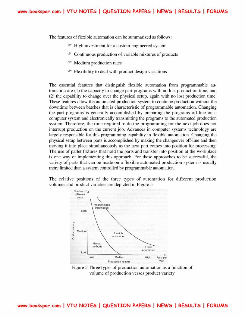
The relative positions of the three types of automation for different production
volumes and product varieties are depicted in Figure 5
Figure 5 Three types of production automation as a function of
volume of production verses product variety
www.bookspar.com | VTU NOTES | QUESTION PAPERS | NEWS | RESULTS | FORUMS
www.bookspar.com | VTU NOTES | QUESTION PAPERS | NEWS | RESULTS | FORUMS

REASONS FOR AUTOMATING
The important reasons for automating include the following:
1. Increased productivity: Automation of manufacturing operations holds the
promise of increasing the productivity of labor. This means greater output per
hour of labor input. Higher production rates (output per hour) are achieved with
automation than with the corresponding manual operations.
2. High cost of labor: The trend in the industrialized societies of the world has
been toward ever-increasing labor costs. As a result, higher investment in
automated equipment has become economically justifiable to replace manual
operations. The high cost of labor is forcing business leaders to substitute
machines for human labor. Because machines can produce at higher rates of
output, the use of automation results in a lower cost per unit of product.
3. Labor shortages: In many advanced nations there has been a general shortage of
labor. Labor shortages also stimulate the development of automation as a
substitute for labor.
4. Trend of labor toward the service sector: This trend has been especially
prevalent in the advanced countries. First around 1986, the proportion of the
work force employed in manufacturing stands at about 20%. In 1947, this
percentage was 30%. By the year 2000, some estimates put the figure as low as
2%, certainly, automation of production jobs has caused some of this shift.
The growth of government employment at the federal, state, and local levels has
consumed a certain share of the labor market which might otherwise have gone
into manufacturing. Also, there has been a tendency for people to view factory
work as tedious, demeaning, and dirty. This view has caused them to seek
employment in the service sector of the economy.
5. Safe: By automating the operation and transferring the operator from an active
participation to a supervisory role, work is made safer. The safety and physical
well-being of the worker has become a national objective with the enactment
of the Occupational. Safety and Health Act of 1970 (OSHA). It has also
provided an impetus for automation.
6. High cost of raw materials: The high cost of raw materials in manufacturing
results in the need for greater efficiency in using these materials. The reduction
of scrap is one of the benefits of automation.
7. Improved product quality: Automated operations not only produce parts at
faster rates than do their manual counterparts, but they produce parts with
greater consistency and conformity to quality specifications.
8. Reduced manufacturing lead time: For reasons that we shall examine in sub
sequent chapters, automation allows the manufacturer to reduce the time between
customer order and product delivery. This gives the manufacturer a
competitive advantage in promoting good customer service.
www.bookspar.com | VTU NOTES | QUESTION PAPERS | NEWS | RESULTS | FORUMS
www.bookspar.com | VTU NOTES | QUESTION PAPERS | NEWS | RESULTS | FORUMS

9. Reduction of in-process inventory: Holding large inventories of work-in-process
represents a significant cost to the manufacturer because it ties up capital. In-
process inventory is of no value. It serves none of the purposes of raw materials
stock or finished product inventory. Accordingly, it is to the manufacturer's
advantage to reduce work-in- progress to a minimum. Automation tends to
accomplish this goal by reducing the time a workpart spends in the factory.
10. High cost of not automating: A significant competitive advantage is gained by
automating a manufacturing plant. The advantage cannot easily be demonstrated
on a company's project authorization form. The benefits of automation often show
up in intangible and unexpected ways, such as improved quality, higher sales,
better labor relations, and better company image. Companies that do not automate
are likely to find themselves at a competitive disadvantage with their customers,
their employees, and the general public.
All of these factors act together to make production automation a feasible and
attractive alternative to manual methods of manufacture.
TYPES OF PRODUCTION
Another way of classifying production activity is according to the quantity of product
made. In this classification, there are three types of production:
1. Job shop production
2. Batch production
3. Mass production
1.Job shop production. The distinguishing feature of job shop production is low volume.
The manufacturing lot sizes are small, often one of a kind. Job shop production is
commonly used to meet specific customer orders, and there is a great variety in the type
of work the plant must do. Therefore, the production equipment must be flexible and
general-purpose to allow for this variety of work. Also, the skill level of job shop workers
must be relatively high so that they can perform a range of different work assignments.
Examples of products manufactured in a job shop include space vehicles, aircraft, machine
tools, special tools and equipment, and prototypes of future products. Construction work
and shipbuilding are not normally identified with the job shop category, even though the
quantities are in the appropriate range. Although these two activities involve the
transformation of raw materials into finished products, the work is not performed in a
factory.
www.bookspar.com | VTU NOTES | QUESTION PAPERS | NEWS | RESULTS | FORUMS
www.bookspar.com | VTU NOTES | QUESTION PAPERS | NEWS | RESULTS | FORUMS

2. Batch production: This category involves the manufacture of medium-sized lots of the
same item or product. The lots may be produced only once, or they may be produced at
regular intervals. The purpose of batch production is often to satisfy continuous customer
demand for an item. However, the plant is capable of a production rate that exceeds the
demand rate. Therefore, the shop produces to build up an inventory of the item. Then it
changes over to other orders. When the stock of the first item becomes depleted, production
is repeated to build up the inventory again. The manufacturing equipment used in batch
production is general-purpose but designed for higher rates of production. Examples of
items made in batch-type shops include industrial equipment, furniture, textbooks, and
component parts for many assembled consumer products (household appliances, lawn
mowers, etc.). Batch production plants include machine shops, casting foundries, plastic
molding factories, and press working shops. Some types of chemical plants are also in
this general category.
3. Mass production: This is the continuous specialized manufacture of identical products.
Mass production is characterized by very high production rates, equipment that is
completely dedicated to the manufacture of a particular product, and very high demand rates
for the product. Not only is the equipment dedicated to one product, but the entire plant is
often designed for the exclusive purpose of producing the particular product. The
equipment is special-purpose rather than general-purpose. The investment in machines
and specialized tooling is high. In a sense, the production skill has been transferred from
the operator to the machine. Consequently, the skill level of labor in a mass production
plant tends to be lower than in a batch plant or job shop.
2.3 FUNCTIONS IN MANUFACTURING
For any of the three types of production, there are certain basic functions that must be
carried out to convert raw materials into finished product. For a firm engaged in making
discrete products, the functions are:
1. Processing
2. Assembly
3. Material handling and storage
4. Inspection and test
5. Control
The first four of these functions are the physical activities that "touch" the product as it is
being made. Processing and assembly are operations that add value to the product. The third
and fourth functions must be performed in a manufacturing plant, but they do not add value
to the product. The Figure 6, shows the model of the functions of manufacturing in factory .
www.bookspar.com | VTU NOTES | QUESTION PAPERS | NEWS | RESULTS | FORUMS
www.bookspar.com | VTU NOTES | QUESTION PAPERS | NEWS | RESULTS | FORUMS

Processing operations
Processing operations transform the product from one state of completion into a more
advanced state of completion. Processing operations can be classified into one of the
following four categories:
1. Basic processes
2. Secondary processes
3. Operations to enhance physical properties
4. Finishing operations
Basic processes are those which give the work material its initial form. Metal casting and
plastic molding are examples. In both cases, the raw materials are converted into the basic
geometry of the desired product.
Secondary processes follow the basic process and are performed to give the work part its final
desired geometry. Examples in this category include machining (turning, drilling, milling,
etc.) and press working operations (blanking, forming, drawing, etc.).
Operations to enhance physical properties do not perceptibly change the physical geometry
of the work part. Instead, the physical properties of the material are improved in some
way. Heat-treating operations to strengthen metal pans and preshrinking used in the
garment industry are examples in this category.
Finishing operations are the final processes performed on the work part. Their purpose is,
for example, to improve the appearance, or to provide a protective coating on the part.
Examples in this fourth category include polishing, painting, and chrome plating.
Figure 6 Model of the factory showing five functions of manufacturing
www.bookspar.com | VTU NOTES | QUESTION PAPERS | NEWS | RESULTS | FORUMS
www.bookspar.com | VTU NOTES | QUESTION PAPERS | NEWS | RESULTS | FORUMS
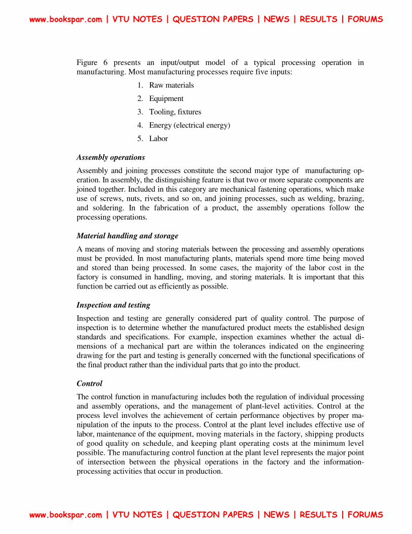
Figure 6 presents an input/output model of a typical processing operation in
manufacturing. Most manufacturing processes require five inputs:
1. Raw materials
2. Equipment
3. Tooling, fixtures
4. Energy (electrical energy)
5. Labor
Assembly operations
Assembly and joining processes constitute the second major type of manufacturing op-
eration. In assembly, the distinguishing feature is that two or more separate components are
joined together. Included in this category are mechanical fastening operations, which make
use of screws, nuts, rivets, and so on, and joining processes, such as welding, brazing,
and soldering. In the fabrication of a product, the assembly operations follow the
processing operations.
Material handling and storage
A means of moving and storing materials between the processing and assembly operations
must be provided. In most manufacturing plants, materials spend more time being moved
and stored than being processed. In some cases, the majority of the labor cost in the
factory is consumed in handling, moving, and storing materials. It is important that this
function be carried out as efficiently as possible.
Inspection and testing
Inspection and testing are generally considered part of quality control. The purpose of
inspection is to determine whether the manufactured product meets the established design
standards and specifications. For example, inspection examines whether the actual di-
mensions of a mechanical part are within the tolerances indicated on the engineering
drawing for the part and testing is generally concerned with the functional specifications of
the final product rather than the individual parts that go into the product.
Control
The control function in manufacturing includes both the regulation of individual processing
and assembly operations, and the management of plant-level activities. Control at the
process level involves the achievement of certain performance objectives by proper ma-
nipulation of the inputs to the process. Control at the plant level includes effective use of
labor, maintenance of the equipment, moving materials in the factory, shipping products
of good quality on schedule, and keeping plant operating costs at the minimum level
possible. The manufacturing control function at the plant level represents the major point
of intersection between the physical operations in the factory and the information-
processing activities that occur in production.
www.bookspar.com | VTU NOTES | QUESTION PAPERS | NEWS | RESULTS | FORUMS
www.bookspar.com | VTU NOTES | QUESTION PAPERS | NEWS | RESULTS | FORUMS

2.4 ORGANIZATION-AMD INFORMATION PROCESSING IN
MANUFACTURING
Manufacturing firms must organize themselves to accomplish the five functions described
above. Figure 7 illustrates the cycle of information-processing activities that typically
occur in a manufacturing firm which produces discrete parts and assembles them into
final products for sale to its customers. The factory operations described in the preceding
section are pictured in the center of the figure. The information-processing cycle, rep-
resented by the outer ring, can be described as consisting of four functions:
1. Business functions
2. Product design
3. Manufacturing planning
4. Manufacturing control
Business functions
The business functions are the principal means of communicating with the customer. They
are the beginning and the end of the information-processing cycle. Included within this
category are sales and marketing, sales forecasting, order entry, cost accounting, customer
billing, and others.
Figure 7 Information-processing cycle in a typical manufacturing firm
www.bookspar.com | VTU NOTES | QUESTION PAPERS | NEWS | RESULTS | FORUMS
www.bookspar.com | VTU NOTES | QUESTION PAPERS | NEWS | RESULTS | FORUMS

An order to produce a product will typically originate from the sales and marketing
department of the firm. The production order will be one of the following forms: (1) an
order to manufacture an item to the customer's specifications, (2) a customer order to buy
one or more of the manufacturer's, proprietary products, or (3) an order based on a forecast
of future demand for a proprietary product.
Product design
If the product is to be manufactured to customer specifications, the design will have been
provided by the customer. The manufacturer's product design department will not be
involved.
If the product is proprietary, the manufacturing firm is responsible for its development and
design. The product design is documented by means of component drawings,
specifications, and a bill of materials that defines how many of each component goes into
the product.
Manufacturing planning
The information and documentation that constitute the design of the product flow into
the manufacturing planning function. The departments in the organization that perform
manufacturing planning include manufacturing engineering, industrial engineering, and
production planning and control.
As shown in Figure 7, the in formation-processing activities in manufacturing planning
include process planning, master scheduling, requirements planning, and capacity
planning. Process planning consists of determining the sequence of the individual
processing and assembly operations needed to produce the part. The document used to
specify the process sequence is called a route sheet. The route sheet lists the production
operations and associated machine tools for each component (and subassembly) of the
product. The manufacturing engineering and industrial engineering departments are
responsible for planning the processes and related manufacturing details. The
authorization to produce the product must be translated into the master schedule or master
production schedule. The master schedule is a listing of the products to be made,
when they are to be delivered, and in what quantities. Units of months are generally used
to specify the deliveries on the master schedule. Based on this schedule, the individual
components and subassemblies that make up each product must be planned. Raw
materials must be requisitioned, purchased parts must be ordered from suppliers, and all
of these items must be planned so that they are available when needed. This whole task is
called requirements planning or material requirements planning. In addition, the master
schedule must not list more quantities of products than the factory is capable of
producing with its given number of machines and workers each month. The production
quantity that the factory is capable of producing is referred to as the plant capacity. We
will define and discuss this term later in the chapter. Capacity planning is concerned
with planning the manpower and machine resources of the firm.
www.bookspar.com | VTU NOTES | QUESTION PAPERS | NEWS | RESULTS | FORUMS
www.bookspar.com | VTU NOTES | QUESTION PAPERS | NEWS | RESULTS | FORUMS

Manufacturing control
Manufacturing control is concerned with managing and controlling the physical
operations in the factory to implement the manufacturing plans.
Shop floor control is concerned with the problem of monitoring the progress of the product
as it is being processed, assembled, moved, and inspected in the factory. The sections of a
traditional production planning and control department that are involved in shop floor
control include scheduling, dispatching, and expediting. Production scheduling is concerned
with assigning start dates and due dates to the various parts (and products) that are to be
made in the factory. This requires that the parts be scheduled one by one through the
various production machines listed on the route sheet for each part. Based on the
production schedule, dispatching involves issuing the individual work orders to the
machine operators to accomplish the processing of the parts. The dispatching function is
performed in some plants by the shop foremen, in other plants by a person called the
dispatcher. Even with the best plans and schedules, things sometimes go wrong (e.g.,
machine breakdowns, improper tooling, parts delayed at the vendor). The expediter
compares the actual progress of a production order against the schedule. For orders that
fall behind, the expediter attempts to take the necessary corrective action to complete the
order on time.
Inventory control overlaps with shop floor control to some extent. Inventory control
attempts to strike a proper balance between the danger of too little inventory (with possible
stock-outs of materials) and the expense of having too much inventory. Shop floor control is
also concerned with inventory in the sense that the materials being processed in the
factory represent inventory (called work-in-process). The mission of quality control is to
assure that the quality of the product and its components meet the standards specified by the
product designer. To accomplish its mission, quality control depends on the inspection
activities performed in the factory at various times throughout the manufacture of the
product. Also, raw materials and components from outside sources must be inspected when
they are received. Final inspection and testing of the finished product is performed to
ensure functional quality and appearance.
2.5 PLANT LAYOUT
In addition to the organizational structure, a firm engaged in manufacturing-must also be
concerned with its physical facilities. The term plant layout refers to the arrangement of
these physical facilities in a production plant. A layout suited to flow-type mass production is
not appropriate for job shop production, and vice versa. There are three principal types of
plant layout associated with traditional production shops:
1. Fixed-position layout
2. Process layout
3. Product-flow layout
www.bookspar.com | VTU NOTES | QUESTION PAPERS | NEWS | RESULTS | FORUMS
www.bookspar.com | VTU NOTES | QUESTION PAPERS | NEWS | RESULTS | FORUMS

1.Fixed-position layout
In this type of layout, the term "fixed-position" refers to the product. Because of its size
and weight, the product remains in one location and the equipment used in its
fabrication is brought to it. Large aircraft assembly and shipbuilding are examples of
operations in which fixed-position layout is utilized. As product is large, the
construction equipment and workers must be moved to the product. This type of
arrangement is often associated with job shops in which complex products are
fabricated in very low quantities.
2.Process layout
In a process layout, the production machines are arranged into groups according to
general type of manufacturing process. The advantage of this type of layout is its
flexibility. Different parts, each requiring its own unique sequence of operations, can be
routed through the respective departments in the proper order.
3.Product-Flow Layout
Productions machines are arranged according to sequence of operations. If a plant
specializes in the production of one product or one class of product in large volumes, the
plant facilities should be arranged to produce the product as efficiently as possible with
this type of layout, the processing and assembly facilities are placed along the line of
flow of the product. As the name implies, this type of layout is appropriate for flow-type
mass production. The arrangement of facilities within the plant is relatively inflexible
and is warranted only when the production quantities are large enough to justify the
investment.
PRODUCTION CONCEPTS AND MATHEMATICAL MODELS
A number of production concepts are quantitative, or require a quantitative approach to
measure them.
Manufacturing lead time
Our description of production is that it consists of a series of individual steps: processing
and assembly operations. Between the operations are material handling, storage, inspec-
tions, and other nonproductive activities. Let us therefore divide the activities in production
into two main categories, operations and non operation elements. An operation on a product
(or work part) takes place when it is at the production machine. The non operation elements
are the handling, storage, inspections, and other sources of delay. Let us use To to denote the
lime per operation at a given machine or workstation, and Tno to represent the non
operation time associated with the same machine. Further, let us suppose that there are nm
separate machines or operations through which the product must be routed in order to be
completely processed. If we assume a batch production situation, there are Q units of the
product in the batch, A setup procedure is generally required to prepare each production
machine for the particular product. The setup typically includes arranging the workplace
and installing the tooling and fixturing required for the product. Let this setup time be
www.bookspar.com | VTU NOTES | QUESTION PAPERS | NEWS | RESULTS | FORUMS
www.bookspar.com | VTU NOTES | QUESTION PAPERS | NEWS | RESULTS | FORUMS

denoted as Tm.
Given these terms, we can define an important production concept, manufacturing lead
time. The manufacturing lead lime (MLT) is the total time required to process a given
product (or work part) through the plant. We can express it as follows:
Where i indicates the operation sequence in the processing, i = 1,2, . .n The MLT
equation does not include the time the raw work part spends in storage before its turn in
the production schedule begins.
Let us assume that all operation times, setup times, and non operation times are equal,
respectively then MLT is given by
For mass production, where a large number of units are made on a single machine, the MLT
simply becomes the operation time for the machine after the setup has been completed and
production begins.
For flow-type mass production, the entire production line is set up in advance. Also, the
non operation time between processing steps consists simply of the time to transfer the
product (or pan) from one machine or workstation to the next. If the workstations are
integrated so that parts are being processed simultaneously at each station, the station with
the longest operation time will determine the MLT value. Hence,
In this case, nm represents the number of separate workstations on the production line.
The values of setup time, operation time, and non operation time are different for the
different production situations. Setting up a flow line for high production requires much
more time than setting up a general-purpose machine in a job shop. However, the concept
of how time is spent in the factory for the various situations is valid.
( )1
mn
sui oi noi
i
MLT T QT T=
= + +∑
( )m su o noMLT n T QT T= + +
( )m oMLT n Transfer time Longst T= +
www.bookspar.com | VTU NOTES | QUESTION PAPERS | NEWS | RESULTS | FORUMS
www.bookspar.com | VTU NOTES | QUESTION PAPERS | NEWS | RESULTS | FORUMS

Problem .1
A certain part is produced in a batch size of 50 units and requires a sequence of eight
operations in the plant. The average setup time is 3 h, and the average operation time per
machine is 6 min. The average non operation time due to handling, delays, inspections,
and so on, is 7 h. compute how many days it will take to produce a batch, assuming that
the plant operates on a 7-h shift per day.
Solution:
The manufacturing lead time is computed from
Production Rate
The production rate for an individual manufacturing process or assembly operation is
usually expressed as an hourly rate (e.g., units of product per hour). The rate will be
symbolized as Rp
Where TP is given by
If the value of Q represents the desired quantity to be produced, and there is a significant
scrap rate, denoted by q, then TP is given by
( )m su o noMLT n T QT T= + +
( )8 3 50 0.1 7 120mMLT Hr= + × + =
1P
P
RT
=
P
Batch time per MachineT
Q=
( )su o
P
T QTT
Q
+=
1o
su
P
QTT
qT
Q
+
− =
www.bookspar.com | VTU NOTES | QUESTION PAPERS | NEWS | RESULTS | FORUMS
www.bookspar.com | VTU NOTES | QUESTION PAPERS | NEWS | RESULTS | FORUMS
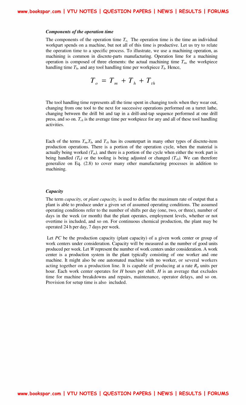
Components of the operation time
The components of the operation time To, The operation time is the time an individual
workpart spends on a machine, but not all of this time is productive. Let us try to relate
the operation time to a specific process. To illustrate, we use a machining operation, as
machining is common in discrete-parts manufacturing. Operation lime for a machining
operation is composed of three elements: the actual machining time Tm, the workpiece
handling time Th, and any tool handling time per workpiece Th. Hence,
The tool handling time represents all the time spent in changing tools when they wear out,
changing from one tool to the next for successive operations performed on a turret lathe,
changing between the drill bit and tap in a drill-and-tap sequence performed at one drill
press, and so on. T,h is the average time per workpiece for any and all of these tool handling
activities.
Each of the terms Tm,Th, and T,h has its counterpart in many other types of discrete-item
production operations. There is a portion of the operation cycle, when the material is
actually being worked (Tm), and there is a portion of the cycle when either the work part is
being handled (Tk) or the tooling is being adjusted or changed (T,h). We can therefore
generalize on Eq. (2.8) to cover many other manufacturing processes in addition to
machining.
Capacity
The term capacity, or plant capacity, is used to define the maximum rate of output that a
plant is able to produce under a given set of assumed operating conditions. The assumed
operating conditions refer to the number of shifts per day (one, two, or three), number of
days in the week (or month) that the plant operates, employment levels, whether or not
overtime is included, and so on. For continuous chemical production, the plant may be
operated 24 h per day, 7 days per week.
Let PC be the production capacity (plant capacity) of a given work center or group of
work centers under consideration. Capacity will be measured as the number of good units
produced per week. Let W represent the number of work centers under consideration. A work
center is a production system in the plant typically consisting of one worker and one
machine. It might also be one automated machine with no worker, or several workers
acting together on a production line. It is capable of producing at a rate Rp units per
hour. Each work center operates for H hours per shift. H is an average that excludes
time for machine breakdowns and repairs, maintenance, operator delays, and so on.
Provision for setup time is also included.
o m h thT T T T= + +
www.bookspar.com | VTU NOTES | QUESTION PAPERS | NEWS | RESULTS | FORUMS
www.bookspar.com | VTU NOTES | QUESTION PAPERS | NEWS | RESULTS | FORUMS

Problem 2
The turret lathe section has six machines, all devoted to production of the same pad. The
section operates 10 shifts per week. The number of hours per shift averages 6.4 because of
operator delays and machine breakdowns. The average production rate is 17 units/h.
Determine the production capacity of the turret lathe section.
Solution:
PC = 6(10)(6.4)(17) = 6528 units/week
If we include the possibility that in a batch production plant, each product is routed through
nm machines, the plant capacity equation must be amended as follows:
Another way of using the production capacity equation is for determining how resources
might be allocated to meet a certain weekly demand rate requirement. Let Dw be the
demand rate for the week in terms of number of units required. Replacing PC and
rearranging, we get
Given a certain hourly production rate for the manufacturing process, indicates three
possible ways of adjusting the capacity up or down to meet changing weekly demand
requirements:
1. Change the number of work centers, W, in the shop. This might be done by using
equipment that was formerly not in use and by hiring new workers. Over the long
term, new machines might be acquired.
2. Change the number of shifts per week, 5W. For example, Saturday shifts might be
authorized.
3. Change the number of hours worked per shift, W. For example, overtime might be
authorized.
In cases where production rates differ, the capacity equations can be revised, summing
the requirements for the different products.
( )W P
m
WS HRPC
n=
( )W m
W
P
D nWS H
R=
( )W m
W
P
D nWS H
R=∑
www.bookspar.com | VTU NOTES | QUESTION PAPERS | NEWS | RESULTS | FORUMS
www.bookspar.com | VTU NOTES | QUESTION PAPERS | NEWS | RESULTS | FORUMS

Problem 3
Three products are to be processed through a certain type of work center. Pertinent data
are given in the following table.
Product Weekly demand Production rale (units/hi
1 600 10
2 1000 20
3 2200 40
Determine the number of work centers required to satisfy this demand, given that the plant
works 10 shifts per week and there are 6.5 h available for production on each work center
for each shift. The value of nm = 1.
Solution:
Product Weekly demand ProductionHrs
1 600 600/10 2 1000 1000/20
3 2200 2200/40
Total production hours required 165
Since each work center can operate (10 shifts/week)(6.5 h) or 65 h/week, the total number
of work centers is
W = 165/65 = 2.54 work centers ≈3
Utilization
Utilization refers to the amount of output of a production facility relative to its capacity.
Letting U represent utilization, we have
OutputU
Capacity=
www.bookspar.com | VTU NOTES | QUESTION PAPERS | NEWS | RESULTS | FORUMS
www.bookspar.com | VTU NOTES | QUESTION PAPERS | NEWS | RESULTS | FORUMS

Problem 4
A production machine is operated 65 h/week at full capacity. Its production rate is 20
units/hr. During a certain week, the machine produced 1000 good parts and was idle the
remaining time.
(a) Determine the production capacity of the machine.
(b) What was the utilization of the machine during the week under consideration?
Solution:
(a) The capacity of the machine can be determined using the assumed 65-h week as
follows:
PC = 65(20) = 1300 units/week
(b) The utilization can be determined as the ratio of the number of parts made during
productive use of the machine relative to its capacity.
Availability
The availability is sometimes used as a measure of-reliability for equipment. It is
especially germane for automated production equipment. Availability is defined using two
other reliability terms, the mean lime between failures (MTBF) and the mean time to
repair (MTTR). The MTBF indicates the average length of time between breakdowns of
the piece of equipment. The MTTR indicates the average time required to service the
equipment and place it back into operation when a breakdown does occur:
Work-in-process
Work-in-process (WIP) is the amount of product currently located in the factory that is
either being processed or is between processing operations. WIP is inventory that is in
the state of being transformed from raw material to finished product. A rough measure of
work-in-process can be obtained from the equation
Where WIP represents the number of units in-process.
100076.92%
1300
OutputU
Capacity= = =
MTBF MTTRAvailability
MTBF
−=
( )W
PC UWIP MLT
S H=
www.bookspar.com | VTU NOTES | QUESTION PAPERS | NEWS | RESULTS | FORUMS
www.bookspar.com | VTU NOTES | QUESTION PAPERS | NEWS | RESULTS | FORUMS

Eugene Merchant, an advocate and spokesman for the manufacturing industry for many
years, has observed that materials in a typical metal machining batch factory spend more
time waiting or being moved than in processing. His observation is illustrated in Figure 8
About 95% of the time of a workpart is spent either moving or waiting; only 5% of its
time is spent on the machine tool. Of this 5%, less than 30% of the time at the machine
(1.5% of the total time of the pan) is time during which actual cutting is taking place. The
remaining 70% (3.5% of the total) is required for loading and unloading, positioning,
gaging, and other causes of nonprocessing time. These time proportions are evidence of
the inefficiencies with which work-in-process is managed in the factory.
Two measures that can be used to assess the magnitude of the work-in-process problem in
a given factory are the WIP ratio and the TIP ratio. The WIP ratio provides an indication
of the amount of inventory-in-process relative to the work actually being processed. It is the
total quantity of a given part (or assembly) in the plant or section of the plant divided by
the quantity of the same part that is being processed (or assembled).
The WIP ratio is therefore determined as
The ideal WIP ratio is 1: 1, which implies that all parts in the plant are being processed.
In a high-volume flow line operation, we would expect the WIP ratio to be relatively
close to I: I if we ignore the raw product that is waiting to be launched onto the line and
the finished product that has been completed. In a batch production shop, the WIP ratio is
significantly higher, perhaps 50: 1 or higher, depending on the average batch size,
nonproductive time, and other factors in the plant.
Figure 8 Time spent a part in batch production shop
Psin
WIPWI ratio
Number of machine proces g=
0
0
sinsu
QTNumber of proces g machine WU
T QT=
+
www.bookspar.com | VTU NOTES | QUESTION PAPERS | NEWS | RESULTS | FORUMS
www.bookspar.com | VTU NOTES | QUESTION PAPERS | NEWS | RESULTS | FORUMS

The TIP ratio measures the time that the product spends in the plant relative to its actual
processing time. It is computed as the total manufacturing lead time for a pan divided by
the sum of the individual operation times for the part.
Again, the ideal TIP ratio is 1: 1, and again it is very difficult to achieve such a low
ratio in practice. In the Merchant observation of Figure 2.6, the TIP ratio = 20: 1.
It should be noted that the WIP and TIP ratios reduce to the same value in our simplified
model of manufacturing presented in this section. This can be demonstrated
mathematically. In an actual factory situation, the WIP and TIP ratios would not nec-
essarily be equal, owing to the complexities and realities encountered in the real world. For
example, assembled products create complications in evaluating the ratio values because
of the combination of parts into one assembly.
AUTOMATION STRATEGIES
There are certain fundamental strategies that tan be employed to improve productivity
in manufacturing operations. Since these strategies are often implemented by means of
automation technology,
1. Specialization of operations: The first strategy involves the use special-
purpose equipment designed to perform one operation with the greatest possible
efficiency. This is analogous to the concept of labor specialization, which has
been employed to improve labor productivity.
2. Combined operations: Production occurs as a sequence of operations. Com-
plex pans may require dozens, or even hundreds, of processing steps. The
strategy of combined operations involves reducing the number of distinct
production machines on workstations through which the part must be routed.
3. Simultaneous operations: A logical extension of the combined operations
strategy is to perform at the same time the operations that are combined at one
workstation. In effect, two or more processing (or assembly) operations are being
performed simultaneously on the same workpart, thus reducing total processing
time.
4. Integration of operations. Another strategy is to link several workstations into
a single integrated mechanism using automated work handling devices to transfer
parts between stations. In effect, this reduces the number of separate machines
through which the product must be scheduled. With more than one workstation,
several parts can be processed simultaneously, thereby increasing the overall
output of the system.
0
Pm
MLTTI ratio
n T=
Reo
duce T
Re , , ,m h no su
duce n T T T
Re , , , ,m h no su o
duce n T T T T
Re , , ,m h no su
duce n T T T
www.bookspar.com | VTU NOTES | QUESTION PAPERS | NEWS | RESULTS | FORUMS
www.bookspar.com | VTU NOTES | QUESTION PAPERS | NEWS | RESULTS | FORUMS
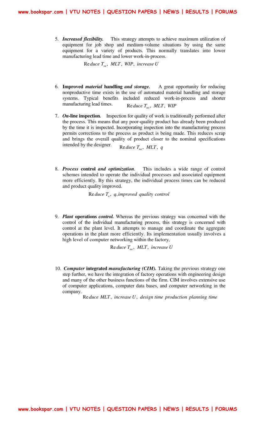
5. Increased flexibility. This strategy attempts to achieve maximum utilization of
equipment for job shop and medium-volume situations by using the same
equipment for a variety of products. This normally translates into lower
manufacturing lead time and lower work-in-process.
6. Improved material handling and storage. A great opportunity for reducing
nonproductive time exists in the use of automated material handling and storage
systems. Typical benefits included reduced work-in-process and shorter
manufacturing lead times.
7. On-line inspection. Inspection for quality of work is traditionally performed after
the process. This means that any poor-quality product has already been produced
by the time it is inspected. Incorporating inspection into the manufacturing process
permits corrections to the process as product is being made. This reduces scrap
and brings the overall quality of product closer to the nominal specifications
intended by the designer.
8. Process control and optimization. This includes a wide range of control
schemes intended to operate the individual processes and associated equipment
more efficiently. By this strategy, the individual process times can be reduced
and product quality improved.
9. Plant operations control. Whereas the previous strategy was concerned with the
control of the individual manufacturing process, this strategy is concerned with
control at the plant level. It attempts to manage and coordinate the aggregate
operations in the plant more efficiently. Its implementation usually involves a
high level of computer networking within the factory,
10. Computer integrated manufacturing (CIM). Taking the previous strategy one
step further, we have the integration of factory operations with engineering design
and many of the other business functions of the firm. CIM involves extensive use
of computer applications, computer data bases, and computer networking in the
company.
Re , , ,suduce T MLT WIP increase U
Re , ,noduce T MLT WIP
Re , ,noduce T MLT q
Re , ,oduce T q improved quality control
Re , ,noduce T MLT increase U
Re , ,duce MLT increase U design time production planning time
www.bookspar.com | VTU NOTES | QUESTION PAPERS | NEWS | RESULTS | FORUMS
www.bookspar.com | VTU NOTES | QUESTION PAPERS | NEWS | RESULTS | FORUMS