
Uni-directional wavelength conversion in silicon using ...
4
Uni-directional wavelength conversion in silicon using four-wave mixing driven by cross-polarized pumps BRYN A. BELL, 1,2, *CHUNLE XIONG, 1,2 DAVID MARPAUNG, 1,2 COLIN J. MCKINSTRIE, 3 AND BENJAMIN J. EGGLETON 1,2 1 Centre for Ultrahigh Bandwidth Devices for Optical Systems (CUDOS), Institute of Photonics and Optical Science (IPOS), School of Physics, University of Sydney, Sydney, NSW 2006, Australia 2 Australian Institute for Nanoscale Science and Technology, University of Sydney, Sydney, NSW 2006, Australia 3 Huawei Technologies, Bridgewater, New Jersey 08807, USA *Corresponding author: [email protected] Received 17 February 2017; accepted 27 March 2017; posted 31 March 2017 (Doc. ID 286968); published 19 April 2017 We demonstrate optical frequency conversion between tele- com wavelengths using four-wave mixing Bragg scattering powered by two pump pulses polarized on orthogonal axes of a silicon waveguide. This allows conversion in a single frequency direction while, with co-polarized pumps, the signal is redshifted or blueshifted with similar efficiency. Our approach exploits the birefringence of the waveguide and its effect on the phase matching of the four-wave mix- ing process. The blue or red direction can be selected by the input polarization of the signal, and 20 dB extinction ratios are observed with the unintended direction. This technique will allow efficient and controlled conversion between specified wavelength channels in integrated photonic devices. © 2017 Optical Society of America OCIS codes: (130.0130) Integrated optics; (130.7405) Wavelength conversion devices; (190.4380) Nonlinear optics, four-wave mixing. https://doi.org/10.1364/OL.42.001668 Four-wave mixing Bragg scattering (FWM-BS) is a χ 3 non- linear process that enables the frequency translation of an op- tical signal by the frequency difference between two stronger pump lasers [1,2], as illustrated in Fig. 1(a). This allows fre- quency shifts in the range of terahertz or hundreds of gigahertz, smaller than in χ 2 processes such as sum- or difference- frequency generation, where the shift is comparable to the whole frequency of a pump laser, but larger than can be directly achieved by electrically driven modulators. This makes FWM- BS suitable, for example, for shifting a signal between dense wavelength division multiplexing (WDM) channels at telecom wavelengths. In principle, FWM-BS is a noiseless process; the total pho- ton number is conserved in the shifted and unshifted signal, in contrast to other four-wave mixing processes such as parametric amplification and phase conjugation, where the transfer of pho- tons from pump(s) to signal results in excess noise [1]. For this reason, it has attracted attention in the context of quantum photonics, where it can be applied to wavelength multiplexing in quantum communications or quantum information process- ing, and to aligning an optical signal with the operating wave- length of a quantum memory or spin-photon interface [3]. The frequency translation of single-photon level signals and heralded single photons has been demonstrated in a photonic crystal fiber [4] and in highly nonlinear fibers [5–7]. Recently, FWM-BS has been demonstrated in photonic chips, such as silicon nitride waveguides [3,8], silicon nitride ring resonators [9], and silicon waveguides [10–12]. Silicon waveguides, in particular, benefit from a narrow Raman peak at around a 15 THz separation, which is easily avoided whereas, in silica fibers, the broad spontaneous Raman scattering of the Fig. 1. (a) Signal is blueshifted using FWM-BS, powered by two pump lasers. The up and down arrows denote the flow of energy into or out of a particular frequency. (b) FWM-BS can also occur in the other direction, with the signal redshifted and the flow of energy be- tween the pumps reversed. (c) When the polarization of one of the pumps is rotated by 90°, the χ 3 tensor dictates that the shifted signal must also be rotated [13]. Here, the orientation of the arrows also in- dicates polarization. (d) For the corresponding redshifting process, the waveguide’ s birefringence creates a large phase mismatch (dk), so this process is forbidden and FWM-BS is uni-directional. 1668 Vol. 42, No. 9 / May 1 2017 / Optics Letters Letter 0146-9592/17/091668-04 Journal © 2017 Optical Society of America
Transcript of Uni-directional wavelength conversion in silicon using ...
Uni-directional wavelength conversion insilicon using four-wave mixing driven bycross-polarized pumpsBRYN A. BELL,1,2,* CHUNLE XIONG,1,2 DAVID MARPAUNG,1,2 COLIN J. MCKINSTRIE,3 AND
BENJAMIN J. EGGLETON1,2
1Centre for Ultrahigh Bandwidth Devices for Optical Systems (CUDOS), Institute of Photonics and Optical Science (IPOS),School of Physics, University of Sydney, Sydney, NSW 2006, Australia2Australian Institute for Nanoscale Science and Technology, University of Sydney, Sydney, NSW 2006, Australia3Huawei Technologies, Bridgewater, New Jersey 08807, USA*Corresponding author: [email protected]
Received 17 February 2017; accepted 27 March 2017; posted 31 March 2017 (Doc. ID 286968); published 19 April 2017
We demonstrate optical frequency conversion between tele-com wavelengths using four-wave mixing Bragg scatteringpowered by two pump pulses polarized on orthogonal axesof a silicon waveguide. This allows conversion in a singlefrequency direction while, with co-polarized pumps, thesignal is redshifted or blueshifted with similar efficiency.Our approach exploits the birefringence of the waveguideand its effect on the phase matching of the four-wave mix-ing process. The blue or red direction can be selected by theinput polarization of the signal, and 20 dB extinction ratiosare observed with the unintended direction. This techniquewill allow efficient and controlled conversion betweenspecified wavelength channels in integrated photonicdevices. © 2017 Optical Society of America
OCIS codes: (130.0130) Integrated optics; (130.7405) Wavelength
conversion devices; (190.4380) Nonlinear optics, four-wave mixing.
https://doi.org/10.1364/OL.42.001668
Four-wave mixing Bragg scattering (FWM-BS) is a χ�3� non-linear process that enables the frequency translation of an op-tical signal by the frequency difference between two strongerpump lasers [1,2], as illustrated in Fig. 1(a). This allows fre-quency shifts in the range of terahertz or hundreds of gigahertz,smaller than in χ�2� processes such as sum- or difference-frequency generation, where the shift is comparable to thewhole frequency of a pump laser, but larger than can be directlyachieved by electrically driven modulators. This makes FWM-BS suitable, for example, for shifting a signal between densewavelength division multiplexing (WDM) channels at telecomwavelengths.
In principle, FWM-BS is a noiseless process; the total pho-ton number is conserved in the shifted and unshifted signal, incontrast to other four-wave mixing processes such as parametricamplification and phase conjugation, where the transfer of pho-tons from pump(s) to signal results in excess noise [1]. For this
reason, it has attracted attention in the context of quantumphotonics, where it can be applied to wavelength multiplexingin quantum communications or quantum information process-ing, and to aligning an optical signal with the operating wave-length of a quantum memory or spin-photon interface [3]. Thefrequency translation of single-photon level signals andheralded single photons has been demonstrated in a photoniccrystal fiber [4] and in highly nonlinear fibers [5–7].
Recently, FWM-BS has been demonstrated in photonicchips, such as silicon nitride waveguides [3,8], silicon nitridering resonators [9], and silicon waveguides [10–12]. Siliconwaveguides, in particular, benefit from a narrow Raman peakat around a 15 THz separation, which is easily avoided whereas,in silica fibers, the broad spontaneous Raman scattering of the
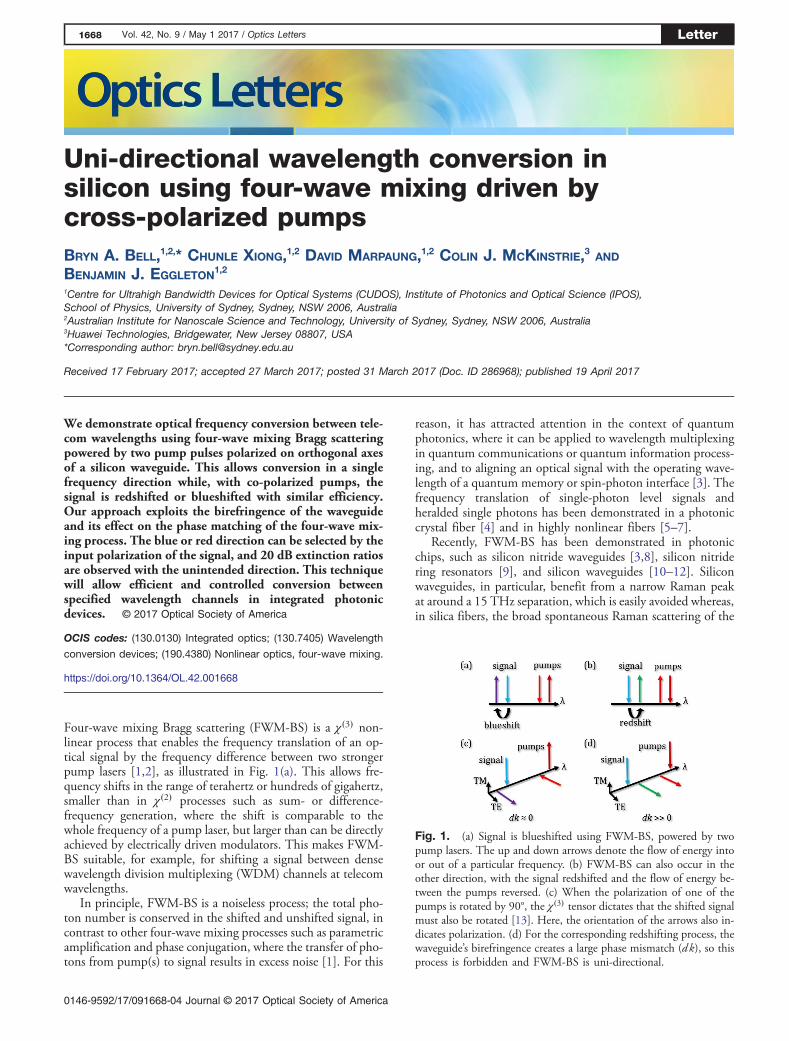
Fig. 1. (a) Signal is blueshifted using FWM-BS, powered by twopump lasers. The up and down arrows denote the flow of energy intoor out of a particular frequency. (b) FWM-BS can also occur in theother direction, with the signal redshifted and the flow of energy be-tween the pumps reversed. (c) When the polarization of one of thepumps is rotated by 90°, the χ�3� tensor dictates that the shifted signalmust also be rotated [13]. Here, the orientation of the arrows also in-dicates polarization. (d) For the corresponding redshifting process, thewaveguide’s birefringence creates a large phase mismatch (dk), so thisprocess is forbidden and FWM-BS is uni-directional.
1668 Vol. 42, No. 9 / May 1 2017 / Optics Letters Letter
0146-9592/17/091668-04 Journal © 2017 Optical Society of America

pumps creates noise photons. This could allow the integrationof noiseless frequency conversion into more complex photonicdevices, for use in classical or quantum communication andinformation processing. Since the length scale is considerablyshorter in these chips compared to fibers, the phase-matchingcondition for FWM-BS is relaxed considerably. Unfortunately,this also means that undesired processes are more likely to bephase matched; in particular, for small shifts, FWM-BSbecomes frequency bi-directional [Fig. 1(b)], and the signalcan be redshifted or blueshifted with roughly equal probability.At higher pump powers, multiple scattering orders can occur,with some of the signal being shifted by an integer multiple ofthe intended shift. This has limited the conversion efficienciesachieved in integrated devices, because some of the signal isshifted to unintended wavelengths; this lack of control overthe output wavelength could also result in undesired interfer-ence when multiple channels are present.
In this Letter, we show that a bi-directional FWM-BSprocess in a silicon waveguide can be made uni-directionalby rotating the polarization of one of the pump lasers by90°, such that the birefringence of the waveguide creates afar larger phase mismatch for the unintended directionthan for the intended one, shown in Figs. 1(c) and 1(d).The dimensions of the waveguide are chosen to provide a rel-atively low birefringence, such that the intended direction isstill close to phase matched, while being sufficient to suppressthe unintended direction. This configuration should alsoprevent multiple scatterings; the converted signal is orthogo-nally polarized to the input signal for this process [13], so itis not phase matched to be shifted a second time. With allthe signal and pumps at telecom wavelengths, we observe fre-quency shifts of 300 GHz with extinction ratios up to 20 dBbetween the intended and unintended directions. To the bestof our knowledge, this is the first use of cross-polarized FWM-BS in waveguide geometry. This could lead to efficient andcontrolled wavelength conversion between WDM channelsin integrated devices, and enable frequency beam splitters asproposed in [14], coupling together two frequency modes ina unitary transformation for quantum logic gates.
The phase mismatch for red- and blueshifting FWM-BS, ingeneral, can be written as
dkred � kin − kout � kp1 − kp2
dkblue � kin − kout − kp1 � kp2: (1)
Here, kin and kout refer to the propagation constants of the in-put and output signals, with kp1 and kp2 those of the longer andshorter wavelength pumps, respectively. Assuming that dkredand dkblue start from approximately zero in the co-polarizedcase and ignoring all dispersion of the refractive indices, theeffect of rotating kp2, and, hence, creating kout on theorthogonal axis, is to create phase mismatches given by
dkred � Δn�ωout � ωp2�∕c;dkblue � Δn�ωout − ωp2�∕c: (2)
Here, ωout and ωp2 refer to the angular frequency of the outputsignal and the shorter wavelength pump, and Δn is the effectiveindex difference between the two polarization modes. dkred isfar larger than dkblue in this case, because it is proportional tothe sum of the two angular frequencies involved, rather than
the difference, so the redshifting process is suppressedcompared to the blue.
The experimental setup is shown in Fig. 2. A mode-lockedlaser (MLL), with a 25 nm bandwidth centered near 1550 nmand a 40 MHz repetition rate, passes through a spectral pulseshaper (SPS) that filters it into three channels: pump 1 (p1) andpump 2 (p2), at 1559.7 and 1557.3 nm, respectively, and aweaker signal (s) at 1539.7 nm. The pump bandwidths were0.1 nm, and the signal bandwidth was 0.2 nm, correspondingto pulse lengths of 35 ps and 18 ps, respectively. All three chan-nels pass through an erbium-doped fiber amplifier (EDFA). Anarrayed waveguide grating with channel spacing of 100 GHz(0.8 nm) is used to divide up the channels; then individualpolarization controllers are applied in each channel. Variableattenuators are used to control the power of each of the pumps,and 99:1 directional couplers and a dual channel power meterare used to monitor their input power. Variable delay lines ineach pump channel and a fixed delay line in the signal channelare used to resynchronize the pulses before they are recombinedby a secondWDM. Lensed fibers are used to couple the light inand out of the silicon waveguide, and the output is measured byan optical spectrum analyzer (OSA).
The silicon waveguide has a height of 3 μm, a width of1.875 μm, and a length of 1 cm [15]. This results in an effectivenonlinear coefficient γ � 5.5 W−1 m−1, a birefringence ofΔn � 2.65 × 10⁻³, and a small normal dispersion for bothpolarizations. Although a larger effective nonlinearity couldbe obtained in a silicon nanowire, the stronger confinementwould also result in a very large birefringence, which wouldmean that FWM-BS with cross-polarized pumps would notbe phase matched in either direction. We find that this largersilicon waveguide has a suitable birefringence to suppress onedirection of FWM-BS while allowing the other. At each facet,this waveguide, which is multi-mode, is tapered into a single-mode rib waveguide, ensuring that light is injected into and
Fig. 2. Experimental setup consists of a broadband MLL followedby a SPS, which filters it into two pump pulses (p1 and p2) and a signal(s). All three go through an EDFA. A wavelength de-multiplexer(WDM) splits the channels, so that they can go through separatepolarization controllers (PCs). The power of each pump is controlledby a variable attenuator (Att.) and monitored using a 1% directionalcoupler and a dual-channel power meter (PM). The pulses are re-synchronized by variable delay lines (vDLs) in each pump channeland a fixed delay line (fDL) in the signal channel; then they are com-bined by a second WDM. Using lensed fibers, they are coupled in andout of a 1 cm silicon waveguide, where FWM-BS occurs, and then theoutput is measured by an OSA.
Letter Vol. 42, No. 9 / May 1 2017 / Optics Letters 1669
collected from the fundamental mode [16]. This resulted incoupling losses of around 1.5 dB per facet, while propagationlosses are expected to be low based on measurements of longerwaveguides, around 0.2 dB in total.
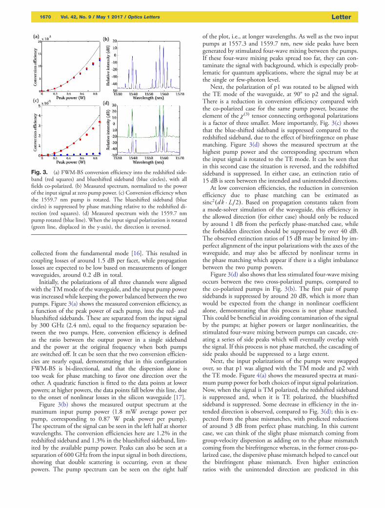
Initially, the polarizations of all three channels were alignedwith the TMmode of the waveguide, and the input pump powerwas increased while keeping the power balanced between the twopumps. Figure 3(a) shows the measured conversion efficiency, asa function of the peak power of each pump, into the red- andblueshifted sidebands. These are separated from the input signalby 300 GHz (2.4 nm), equal to the frequency separation be-tween the two pumps. Here, conversion efficiency is definedas the ratio between the output power in a single sidebandand the power at the original frequency when both pumpsare switched off. It can be seen that the two conversion efficien-cies are nearly equal, demonstrating that in this configurationFWM-BS is bi-directional, and that the dispersion alone istoo weak for phase matching to favor one direction over theother. A quadratic function is fitted to the data points at lowerpowers; at higher powers, the data points fall below this line, dueto the onset of nonlinear losses in the silicon waveguide [17].
Figure 3(b) shows the measured output spectrum at themaximum input pump power (1.8 mW average power perpump, corresponding to 0.87 W peak power per pump).The spectrum of the signal can be seen in the left half at shorterwavelengths. The conversion efficiencies here are 1.2% in theredshifted sideband and 1.3% in the blueshifted sideband, lim-ited by the available pump power. Peaks can also be seen at aseparation of 600 GHz from the input signal in both directions,showing that double scattering is occurring, even at thesepowers. The pump spectrum can be seen on the right half
of the plot, i.e., at longer wavelengths. As well as the two inputpumps at 1557.3 and 1559.7 nm, new side peaks have beengenerated by stimulated four-wave mixing between the pumps.If these four-wave mixing peaks spread too far, they can con-taminate the signal with background, which is especially prob-lematic for quantum applications, where the signal may be atthe single or few-photon level.
Next, the polarization of p1 was rotated to be aligned withthe TE mode of the waveguide, at 90° to p2 and the signal.There is a reduction in conversion efficiency compared withthe co-polarized case for the same pump power, because theelement of the χ�3� tensor connecting orthogonal polarizationsis a factor of three smaller. More importantly, Fig. 3(c) showsthat the blue-shifted sideband is suppressed compared to theredshifted sideband, due to the effect of birefringence on phasematching. Figure 3(d) shows the measured spectrum at thehighest pump power and the corresponding spectrum whenthe input signal is rotated to the TE mode. It can be seen thatin this second case the situation is reversed, and the redshiftedsideband is suppressed. In either case, an extinction ratio of15 dB is seen between the intended and unintended directions.
At low conversion efficiencies, the reduction in conversionefficiency due to phase matching can be estimated assinc2�dk · L∕2�. Based on propagation constants taken froma mode-solver simulation of the waveguide, this efficiency inthe allowed direction (for either case) should only be reducedby around 1 dB from the perfectly phase-matched case, whilethe forbidden direction should be suppressed by over 40 dB.The observed extinction ratios of 15 dB may be limited by im-perfect alignment of the input polarizations with the axes of thewaveguide, and may also be affected by nonlinear terms inthe phase matching which appear if there is a slight imbalancebetween the two pump powers.
Figure 3(d) also shows that less stimulated four-wave mixingoccurs between the two cross-polarized pumps, compared tothe co-polarized pumps in Fig. 3(b). The first pair of pumpsidebands is suppressed by around 20 dB, which is more thanwould be expected from the change in nonlinear coefficientalone, demonstrating that this process is not phase matched.This could be beneficial in avoiding contamination of the signalby the pumps; at higher powers or larger nonlinearities, thestimulated four-wave mixing between pumps can cascade, cre-ating a series of side peaks which will eventually overlap withthe signal. If this process is not phase matched, the cascading ofside peaks should be suppressed to a large extent.
Next, the input polarizations of the pumps were swappedover, so that p1 was aligned with the TM mode and p2 withthe TE mode. Figure 4(a) shows the measured spectra at maxi-mum pump power for both choices of input signal polarization.Now, when the signal is TM polarized, the redshifted sidebandis suppressed and, when it is TE polarized, the blueshiftedsideband is suppressed. Some decrease in efficiency in the in-tended direction is observed, compared to Fig. 3(d); this is ex-pected from the phase mismatches, with predicted reductionsof around 3 dB from perfect phase matching. In this currentcase, we can think of the slight phase mismatch coming fromgroup-velocity dispersion as adding on to the phase mismatchcoming from the birefringence whereas, in the former cross-po-larized case, the dispersive phase mismatch helped to cancel outthe birefringent phase mismatch. Even higher extinctionratios with the unintended direction are predicted in this
Fig. 3. (a) FWM-BS conversion efficiency into the redshifted side-band (red squares) and blueshifted sideband (blue circles), with allfields co-polarized. (b) Measured spectrum, normalized to the powerof the input signal at zero pump power. (c) Conversion efficiency whenthe 1559.7 nm pump is rotated. The blueshifted sideband (bluecircles) is suppressed by phase matching relative to the redshifted di-rection (red squares). (d) Measured spectrum with the 1559.7 nmpump rotated (blue line). When the input signal polarization is rotated(green line, displaced in the y-axis), the direction is reversed.
1670 Vol. 42, No. 9 / May 1 2017 / Optics Letters Letter
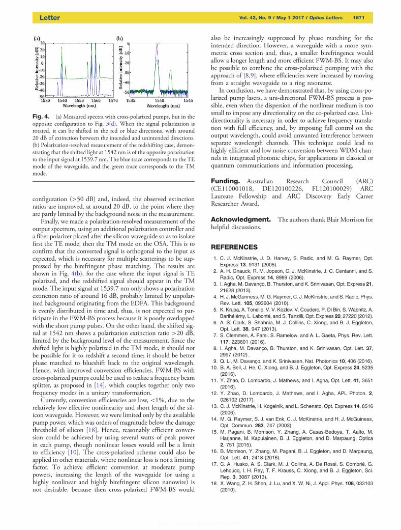
configuration (>50 dB) and, indeed, the observed extinctionratios are improved, at around 20 dB, to the point where theyare partly limited by the background noise in the measurement.
Finally, we made a polarization-resolved measurement of theoutput spectrum, using an additional polarization controller anda fiber polarizer placed after the silicon waveguide so as to isolatefirst the TE mode, then the TM mode on the OSA. This is toconfirm that the converted signal is orthogonal to the input asexpected, which is necessary for multiple scatterings to be sup-pressed by the birefringent phase matching. The results areshown in Fig. 4(b), for the case where the input signal is TEpolarized, and the redshifted signal should appear in the TMmode. The input signal at 1539.7 nm only shows a polarizationextinction ratio of around 16 dB, probably limited by unpolar-ized background originating from the EDFA. This backgroundis evenly distributed in time and, thus, is not expected to par-ticipate in the FWM-BS process because it is poorly overlappedwith the short pump pulses. On the other hand, the shifted sig-nal at 1542 nm shows a polarization extinction ratio >20 dB,limited by the background level of the measurement. Since theshifted light is highly polarized in the TM mode, it should notbe possible for it to redshift a second time; it should be betterphase matched to blueshift back to the original wavelength.Hence, with improved conversion efficiencies, FWM-BS withcross-polarized pumps could be used to realize a frequency beamsplitter, as proposed in [14], which couples together only twofrequency modes in a unitary transformation.
Currently, conversion efficiencies are low, <1%, due to therelatively low effective nonlinearity and short length of the sil-icon waveguide. However, we were limited only by the availablepump power, which was orders of magnitude below the damagethreshold of silicon [18]. Hence, reasonably efficient conver-sion could be achieved by using several watts of peak powerin each pump, though nonlinear losses would still be a limitto efficiency [10]. The cross-polarized scheme could also beapplied in other materials, where nonlinear loss is not a limitingfactor. To achieve efficient conversion at moderate pumppowers, increasing the length of the waveguide (or using ahighly nonlinear and highly birefringent silicon nanowire) isnot desirable, because then cross-polarized FWM-BS would
also be increasingly suppressed by phase matching for theintended direction. However, a waveguide with a more sym-metric cross section and, thus, a smaller birefringence wouldallow a longer length and more efficient FWM-BS. It may alsobe possible to combine the cross-polarized pumping with theapproach of [8,9], where efficiencies were increased by movingfrom a straight waveguide to a ring resonator.
In conclusion, we have demonstrated that, by using cross-po-larized pump lasers, a uni-directional FWM-BS process is pos-sible, even when the dispersion of the nonlinear medium is toosmall to impose any directionality on the co-polarized case. Uni-directionality is necessary in order to achieve frequency transla-tion with full efficiency, and, by imposing full control on theoutput wavelength, could avoid unwanted interference betweenseparate wavelength channels. This technique could lead tohighly efficient and low noise conversion between WDM chan-nels in integrated photonic chips, for applications in classical orquantum communications and information processing.
Funding. Australian Research Council (ARC)(CE110001018, DE120100226, FL120100029) ARCLaureate Fellowship and ARC Discovery Early CareerResearcher Award.
Acknowledgment. The authors thank Blair Morrison forhelpful discussions.
REFERENCES
1. C. J. McKinstrie, J. D. Harvey, S. Radic, and M. G. Raymer, Opt.Express 13, 9131 (2005).
2. A. H. Gnauck, R. M. Jopson, C. J. McKinstrie, J. C. Centanni, and S.Radic, Opt. Express 14, 8989 (2006).
3. I. Agha, M. Davanço, B. Thurston, and K. Srinivasan, Opt. Express 21,21628 (2013).
4. H. J. McGunness, M. G. Raymer, C. J. McKinstrie, and S. Radic, Phys.Rev. Lett. 105, 093604 (2010).
5. K. Krupa, A. Tonello, V. V. Kozlov, V. Couderc, P. Di Bin, S.Wabnitz, A.Barthélémy, L. Labonté, and S. Tanzilli, Opt. Express 20, 27220 (2012).
6. A. S. Clark, S. Shahnia, M. J. Collins, C. Xiong, and B. J. Eggleton,Opt. Lett. 38, 947 (2013).
7. S. Clemmen, A. Farsi, S. Ramelow, and A. L. Gaeta, Phys. Rev. Lett.117, 223601 (2016).
8. I. Agha, M. Davanço, B. Thurston, and K. Srinivasan, Opt. Lett. 37,2997 (2012).
9. Q. Li, M. Davanço, and K. Srinivasan, Nat. Photonics 10, 406 (2016).10. B. A. Bell, J. He, C. Xiong, and B. J. Eggleton, Opt. Express 24, 5235
(2016).11. Y. Zhao, D. Lombardo, J. Mathews, and I. Agha, Opt. Lett. 41, 3651
(2016).12. Y. Zhao, D. Lombardo, J. Mathews, and I. Agha, APL Photon. 2,
026102 (2017).13. C. J. McKinstrie, H. Kogelnik, and L. Schenato, Opt. Express 14, 8516
(2006).14. M. G. Raymer, S. J. van Enk, C. J. McKinstrie, and H. J. McGuiness,
Opt. Commun. 283, 747 (2003).15. M. Pagani, B. Morrison, Y. Zhang, A. Casas-Bedoya, T. Aalto, M.
Harjanne, M. Kapulainen, B. J. Eggleton, and D. Marpaung, Optica2, 751 (2015).
16. B. Morrison, Y. Zhang, M. Pagani, B. J. Eggleton, and D. Marpaung,Opt. Lett. 41, 2418 (2016).
17. C. A. Husko, A. S. Clark, M. J. Collins, A. De Rossi, S. Combrié, G.Lehoucq, I. H. Rey, T. F. Krauss, C. Xiong, and B. J. Eggleton, Sci.Rep. 3, 3087 (2013).
18. X. Wang, Z. H. Shen, J. Lu, and X. W. Ni, J. Appl. Phys. 108, 033103(2010).
Fig. 4. (a) Measured spectra with cross-polarized pumps, but in theopposite configuration to Fig. 3(d). When the signal polarization isrotated, it can be shifted in the red or blue directions, with around20 dB of extinction between the intended and unintended directions.(b) Polarization-resolved measurement of the redshifting case, demon-strating that the shifted light at 1542 nm is of the opposite polarizationto the input signal at 1539.7 nm. The blue trace corresponds to the TEmode of the waveguide, and the green trace corresponds to the TMmode.
Letter Vol. 42, No. 9 / May 1 2017 / Optics Letters 1671