
Ulznan IDE for cmnn-nof mbeddedrl-msoftwarefor n...
28
Utilizing an IDE for component-based design of embedded real-time software for an autonomous car Jimmie Wiklander, Johan Eriksson, and Per Lindgren Abstract Embedded systems are inherently reactive and they often operate under resource and real-time constraints. Hence, a model supporting these fundamental properties is desirable for an efficient and correct design process. To this end, we have developed a component model and design methodology that enables component-based design of embedded software. Moreover, we have developed an Integrated Development Environ- ment (IDE) that ensures a systematic development of software in accordance with the methodology. In this paper we review the IDE and it’s underlying modeling framework and demonstrate its applicability through a use-case with typical properties - a control system with real-time constraints and hardware interaction. This paper describes the whole design process – requirements specification, concep- tual model, component-level design, component implementation, code synthesis, testing, and verification. In particular, we show how the modeling framework enforces a static component and communication structure reflecting the concurrent behavior of the sys- tem and its interaction with the environment (target platform). Our results (a working protoype) indicate applicability of the presented design approach, and show the IDE’s ability to generate efficient executables. Additionally, we show how to prove the schedu- lability of the target system in the IDE using standard scheduling theorems and machine assisted WCET measurements. In conclusion, this paper demonstrates both the applicability of the software design methodology and the functionality of the developed IDE. 1 Introduction Tool support is instrumental for efficient and correct design of embedded software. In this paper we show how to design the software for an autonomous car using an Integrated Development Environment (IDE) (Fig. 1). The IDE supports component-based software design for resource-constrained embed- ded systems with hard real-time requirements. The underlying modeling framework [1] is based upon a reactive view in which the functionality of the system is modeled as reac- tions to events that originate in the systems environment or internally within the system itself. Moreover, the modeling framework supports specifying the timing constraints for the reaction to an event. 139
-
Upload
vuongquynh -
Category
Documents
-
view
245 -
download
0
Transcript of Ulznan IDE for cmnn-nof mbeddedrl-msoftwarefor n...

Utilizing an IDE for component-based design of
embedded real-time software for an autonomous car
Jimmie Wiklander, Johan Eriksson, and Per Lindgren
Abstract
Embedded systems are inherently reactive and they often operate under resourceand real-time constraints. Hence, a model supporting these fundamental properties isdesirable for an efficient and correct design process. To this end, we have developeda component model and design methodology that enables component-based design ofembedded software. Moreover, we have developed an Integrated Development Environ-ment (IDE) that ensures a systematic development of software in accordance with themethodology. In this paper we review the IDE and it’s underlying modeling frameworkand demonstrate its applicability through a use-case with typical properties - a controlsystem with real-time constraints and hardware interaction.
This paper describes the whole design process – requirements specification, concep-tual model, component-level design, component implementation, code synthesis, testing,and verification. In particular, we show how the modeling framework enforces a staticcomponent and communication structure reflecting the concurrent behavior of the sys-tem and its interaction with the environment (target platform). Our results (a workingprotoype) indicate applicability of the presented design approach, and show the IDE’sability to generate efficient executables. Additionally, we show how to prove the schedu-lability of the target system in the IDE using standard scheduling theorems and machineassisted WCET measurements.
In conclusion, this paper demonstrates both the applicability of the software designmethodology and the functionality of the developed IDE.
1 Introduction
Tool support is instrumental for efficient and correct design of embedded software. Inthis paper we show how to design the software for an autonomous car using an IntegratedDevelopment Environment (IDE) (Fig. 1).
The IDE supports component-based software design for resource-constrained embed-ded systems with hard real-time requirements. The underlying modeling framework [1]is based upon a reactive view in which the functionality of the system is modeled as reac-tions to events that originate in the systems environment or internally within the systemitself. Moreover, the modeling framework supports specifying the timing constraints forthe reaction to an event.
139

140 Paper E
Figure 1: The IDE illustrated in terms of a screenshot of the autonomous car design presentedin this paper.
The IDE supports defining a model of the software system based on interaction withthe system platform (e.g. a microcontroller and its peripherals in terms of sensors, motorsetc.). The structure of the software system is defined graphically and the functionality isdefined using a subset of C. From the model it is possible to generate C code that can becompiled for execution on a hardware platform assisted by a real-time kernel. Distinctiveto our approach is that timing requirements are captured as part of the model and arepreserved throughout the design process; they are utilized by our kernel for schedulingat run-time. A brief overview of the tool can be found in [2].
The specification for the autonomous car comes from a mechatronics project courseat the university. In this course the students are divided into teams and each team designand build their own autonomous car by modifying a standard radio controlled model car.The function of the autonomous car is to track an IR signal coming from a beacon andthen direct its way towards the beacon and make a full stop in front of it. The course isconcluded with a single-elimination tournament where the cars race each other on whoarrives first to the beacon. In this case study the target platform for the software designis one of the student cars (including its onboard sensors, servos, and microcontroller).This system is representative for the type of systems addressed by the IDE, i.e. resourceconstrained embedded systems with hard real-time requirements.
The rest of the paper is organized as follows. In the next section (Section 2) wepresent an overview of the IDE. It is followed by related work (Section 3). The problemstatement as defined in the mechatronics course is presented in Section 4. In Section 5 weoutline the conceptual model of the autonomous car and in Section 6 we present the targetplatform for the software implementation. The software design for the autonomous car ispresented in Section 7 and the details of the program analysis is presented in Section 8.

2. IDE Overview 141
Finally, in Section 9 we present the conclusions of this case study.
2 IDE Overview
The aim of the IDE is to construct a model of the software system based on its interactionwith the environment and to generate efficient C code from the model for execution onbare metal. More specifically, the system structure is defined graphically by composingcomponents and the functionality of the components is defined using C code. An impor-tant aspect of the model is that it supports specifying not only the functionality of eachcomponent but also its intended timing behavior. Moreover, the model supports inde-pendent definition of components, that is, the properties defined locally for a componentare not affected by external factors. For a real-time system to be correct its run-timebehavior should comply with the specification. This is achieved by preserving the modeland its timing requirements in the generated code all the way to the executable andallowing for the scheduler to utilize the timing requirements for scheduling at run time.Generating code from a static component composition enables using static verificationand optimization techniques to achieve low overhead and predictability of the systembehavior at run-time.
2.1 Modeling framework
The modeling framework is based on the notions of components and time-constrainedreactions. A more detailed presentation of the framework can be found in [1]. Note thatin [1] we make a distinction between reactive objects [3] and components. In this work wedo not make this distinction and we denote the reactive objects themselves as concurrentreactive components. In this section we highlight the key aspects of time-constrainedreactions, concurrent reactive components, and discuss modeling interaction betweenconcurrent reactive components as well as a system’s interaction with its environment.
Time-Constrained Reactions
Time-constrained reactions [4] lie at the heart of our model. Interaction between thesystem and its environment, as well as between components of the system is modeledas discrete events (i.e. events occurring at specific points in time). Following a reactiveapproach, functionality is specified in terms of time-constrained reactions to such events.
Timing requirements on system operation can be specified by defining the earliestand the latest reaction time (baseline and deadline) relative to the time of the eventtriggering the reaction. The time window between the reaction baseline and its deadlineis called a permissible execution window for this reaction (Fig. 2).
Concurrent Reactive Components
The fundamental modeling construct of the framework is a concurrent reactive compo-nent (CRC) [3]. Note that what is denoted CRC in this work is known as reactive object

142 Paper E
���������� ����������
������������������������
��������
�������
������
Figure 2: A permissible execution window for a reaction to an event. Here tafter is the baselineoffset, tbefore is the time between the baseline and the deadline.
in [3]. Each component may have a state, one or several methods and it may encapsulatea number of other components, creating a hierarchical structure. It is reactive in thesense that it reacts to an incoming event by executing one of its methods or invokinga method of an underlying component. Each CRC has a provided interface (the meth-ods, or input ports, of the component that can be invoked by other components) and arequired interface (the methods, or output ports, in the components’s environment thatit may invoke). In the model, an output port in the required interface of a componentcan be linked to an input port in the provided interface of another component, creatinga communication path between two different CRCs. Multiple output ports can be con-nected to a single input port. Each CRC is either idle (maintaining its state) or executesa method. Methods execute run-to-end, that is, once a method has started execution,no other method of the same CRC may preempt it. However, any two methods of dif-ferent CRCs may execute concurrently. A method’s code can perform computations onlocal variables, read/mutate the component’s state, and invoke a method of the same oranother component by sending a message to it.
Messages sent between components can be of two kinds: asynchronous, which areexecuted concurrently with the caller and can be delayed by a certain amount of time,and synchronous, with the caller blocked until the invoked method completes execution,optionally returning a value (such methods cannot be delayed). The permissible executionwindow of an asynchronous message can be either inherited or explicitly specified in thecode relatively to the caller’s baseline; in either case, it is viewed in the model as aseparate reaction. A synchronous message, on the other hand, always inherits the caller’stime constraints and is viewed as a part of the original time-constrained reaction. Bothasynchronous and synchronous messages can carry data (the values of arguments of theinvoked methods).
Classes and Instances
Every CRC has a class definition from which instances can be created at run-time. Theclass definition can be defined at the top level or locally within another class; in thelatter case, it can only be used inside that class and the classes that are hierarchicallyencompassed by the class. A CRC definition defines the component’s state variables,methods (these are written manually in C), and the provided and required interfaces ofthe component. In the C code of a method we may:
1. define local variables,

3. Related Work 143
2. read/update the component’s state,
3. perform calculations on the component’s state, method argument, and local vari-ables,
4. invoke an asynchronous method of this component or of another component usingthe name of an output port or a port of the provided interface of an encapsulatedcomponent (see Fig. 2):
ASYNC(PortName, BaselineOffset,
RelativeDeadline, Argument)
5. invoke a synchronous method of another component using the name of an outputport or a port of the provided interface of an encapsulated component:
SYNC(PortName, Argument)
6. return a value (only meaningful if the method is synchronous).
The current implementation of the tool does not verify that the C code complies withthe model’s requirements as outlined above but this will be added later.
Kernel support and interaction with the environment
A system model (i.e. the system’s structure in terms of CRCs and communication pathsbetween them, and C code written for each method) is used to generate C code represent-ing the software system. Execution on a hardware platform also requires infrastructuresupporting the model in the form of a lightweight kernel supporting scheduling of methodexecution and message passing between components.
Embedded systems interact with their environment and this must be reflected in themodel. This is modeled using a special construct, an environment interface that definesan interface to the hardware. An instance of an environment interface enables readingfrom hardware registers and writing to them and is also used to connect specific hardwareinterrupts to asynchronous methods of particular components. The model does not makeany assumptions regarding the behavior of the environment.
Sometimes it is necessary to include legacy software that is not based on the CRCmodel (typically, external software libraries). Such libraries can be treated as part of thesystem’s environment, and we can use an environment interface as a wrapper to legacycode.
3 Related Work
There is a strong interest for component-based design of embedded software. As a result,various approaches and component models have been proposed. We have selected afew of these approaches for a comparison against our approach as presented below. In

144 Paper E
particular, we have selected approaches targeting software development for resource-constrained embedded systems. Such systems are typically interrupt driven, i.e. theymust respond to events that originate in their environment (i.e. the physical world),often with real-time requirements. Moreover, it is becoming increasingly common forthese systems to perform multiple tasks at the same time. Hence, the normal operationfor such systems is the reactive execution of concurrent events.
Our model for developing systems is reactive, which means that the natural behaviorof the modeling constructs (CRCs) is to react to events. Moreover, the model allowsto express concurrency simply by specifying functionality in terms of separate CRCs.Hence, the model eliminates the need for manually specifying concurrency (e.g. threads,mutexes, etc.) which often lead to incorrect code with bugs that are are hard to decipher(race conditions, deadlocks, etc.). In our approach, this view can be maintained even forsystems with scheduling.
TinyOS [5] targets building concurrent, reactive applications for resource-constrainedsystems. Its component model is similar to the CRC model. A module in TinyOS can beseen as a CRC that is prohibited to encapsulate inner CRCs. Moreover, a configurationcan be seen as a CRC that is prohibited to contain anything other than inner CRCs.Hence, the TinyOS model supports constructing hierarchical models in the same manneras the CRC model. Moreover, TinyOS modules encapsulates state, as does CRCs. Incontrast to the CRC model, the concurrency is not modeled in terms of components,instead TinyOS expresses concurrency in terms of asynchronous code that can be invokedby interrupt handlers. The execution model in TinyOS is based on run-to-completiontasks and event handlers. The standard TinyOS task scheduler uses a non-preemptive,FIFO scheduling policy. TinyOS application are well suited for execution on resource-constrained systems. However, TinyOS offer limited support for developing real-timeapplications.
The Rubus Component Model (RCM) [6, 7] targets development of resource con-strained embedded real-time systems. Like the CRC model, it supports constructing amodel of a system by composing modeling constructs graphically. However, as in theTinyOS case, RCM distinguishes between the basic component which is called a Soft-ware Circuit (SWC) and the assembly which enables constructing hierarchical models.SWCs are used for encapsulating software functions. The software functions are mappedto tasks at a later stage of the design process. Similar to our approach, RCM supportsexpressing timing requirements and analyzing the resource demands for a particular hard-ware platform. Further, the run-time system supports executing all tasks on a sharedstack. This is supported in our methodology as well through SRP resource management.In contrast to the CRC model and the REKO IDE, RCM and its tool suite has beenused in the industry for the development of embedded software for many years.
It is also worth mentioning AmbientRT [8] which is a real-time operating system forembedded devices with resource-constraints in terms of memory, processing, and energyresources. This approach does not offer any tools for composing components to a softwaremodel. However, it supports loading blocks of precompiled software and executing theblocks dynamically. Hence, it enables creating new software configurations online. Like in

4. Problem Statement 145
�����&���
�����
������ �
�� ����
����
�
�������
�� ���
�� � ������
������
Figure 3: A schematic of the two competing cars and the race track. Each car has an opticalsensor that can be panned which enables measuring the horizontal angle δ between the IR emit-ting rows. The angle δ is used to determine the direction and distance to the beacon relative tothe car.
our approach, a guarantee on meeting the real-time constraints for each task can be giventhrough analysis. The AmbientRT kernel supports real-time scheduling of tasks usingSRP-EDF. In contrast, the REKO IDE targets SRP-DM scheduling which is less flexiblecompared to SRP-EDF but allows for more efficient implementation onto commonplacehardware. However, for the autonomous car it was sufficient to use non-preemptive DMscheduling (similar to the scheduling provided by TinyOS).
4 Problem Statement
The team should design and build an autonomous car. The car should track an IR signalcoming from a beacon and then direct its way towards the beacon and make a full stopin front of it. The car should be equipped with an optical sensor which can detect theIR signal from a distance of 10 meter in daylight. The sensor signal should be processedby electronic hardware designed and built by the team. The processed signal shouldthen be feed to the ADC in the onboard AVR microcontroller. The whole sensor unitwill be mounted on a standard RC servo which enables the sensor to be panned in thehorizontal plane. The beacon has two vertical rows of IREDs which emit IR radiationwith a wavelength of 900 nm. The horizontal distance between the rows is 95 mm. Thehorizontal angle between the IR emitting rows (δ in Fig. 3) can be measured by thepanning optical sensor. The panning servo, the speed and front wheel steering angle ofthe car is controlled by the microcontroller.
The cars compete in a single elimination tournament. In every round two cars competein a best two-of-three format. The cars are placed side by side behind a starting line ata 10 m distance from the beacon (see Fig. 3) facing the beacon1. On a given start signalthe cars are activated by the team. The cars should drive autonomously to the beacon asfast as possible. The goal position is defined as a circle with one meter in diameter placedbetween the start line and the beacon in such a way that the vertical projection of theemitting rows lies on the circle. The winner is the car which first enters the circle with
1In this work we want the autonomous car to be able to locate and track the beacon even if it is not
facing the beacon to start with.

146 Paper E
a wheel and stops (the wheel must remain within the circle after the car has stopped).The beacon must not be touched by the car.
5 Conceptual Model
Following the problem statement the car should continuously track the IR signal and drivetowards the beacon (a.k.a. guidance). Guidance is usually implemented in accordancewith some routing strategy. From the problem statement we formulated the followingconceptual model.
5.1 Target tracking
The beacon has 14 IREDs positioned in two vertical columns with a horizontal distanceof 95 mm. The IREDs emit an IR pulse with 900 nm wavelength. The optical sensor ofthe car measures the intensity of the signal while being panned from side to side.
The angular direction of the target (β in Fig. 4) is defined as the angular directionbetween the centerline of the car and the imaginary line from the midpoint of the rearaxis to the midpoint of the IRED columns. This angle is derived by monitoring thepanning angle of the sensor when the sensor registers the outer IRED column edgesduring a panning cycle (panning from one side to the other). The angular direction isequivalent to the intermediate angle between the two registered angles. When the caris far from the target the column edges will be recognized as a single entity making theangular direction equivalent to the panning angle.
Note that in order to get the accurate panning angle the sensor should be mountedat the midpoint of the rear axis. In our case there will be a deviation in the registeredpanning angle due to the sensor being positioned at the midpoint of the front axis insteadof the midpoint of the rear axis. However, the deviation was considered to be acceptablefor our purposes.
The distance d to the target (see Fig. 4) is calculated using the following equation
d =b
cos(δ)(1)
where b is the horizontal distance between and δ is the horizontal angle between the twoIRED columns (see Fig. 3).
5.2 Routing Strategy
The routing strategy is based on following a circular arc passing through the midpointof the rear axis of the car and the target point where the centerline of the car is astangent to the circular arc (see Fig. 4). Hence, the radius of the circular arc depends onthe positioning of the car relative to the target. The following equation computes thesteering angle (α) that the car should take on in order to follow the circular arc.
α = arctan2a sin β
d(2)

6. Target Platform for the Software Implementation 147
�
������
�
�
�
��������
���� �����
Figure 4: The routing strategy is based on following a circular arc to the target.
where β is the angle between the centerline of the car and the imaginary line from themidpoint of the rear axis to the target, a is the distance between the front and rear axis,and d is the distance between the midpoint of the rear axis and the target.
5.3 Guidance
Guidance uses the targeting information to control the steering and speed of the car. Itcontinuously calculates the steering angle (Eq. 2) based on the latest sensor readings.The speed of the car depends on the distance between the car and the target. When thetarget is far away the speed is set to maximum and when it approaches the target thespeed is decreased. When the target is not visible by the sensor the speed is set to lowand the steering is set to turn full left aiming to locate the target.
5.4 Modes of Operation
The car should have two different modes of operation: neutral and drive. The car shouldstart in the neutral mode and it should be possible to switch between the modes manuallyby pushing a button on the car. In the neutral mode the car should track the target andcalculate the route but it should not move. In the drive mode the car should direct itsway towards the beacon and make a full stop in front of it.
6 Target Platform for the Software Implementation
The RC car has an onboard microcontroller (AVR – AT90CAN128) that enables control-ling the servos of the car and reading data from the optical sensor. However, a softwareimplementation must be provided in order to enable the car to autonomously track thetarget and direct its way towards the target. More specifically, our software implementa-tion should read data from the optical sensor, calculate the position of the target (headingand distance), calculate a route to the target following a specific routing strategy, andhave the car to follow the anticipated route by setting the control signals of the servos.
148 Paper E
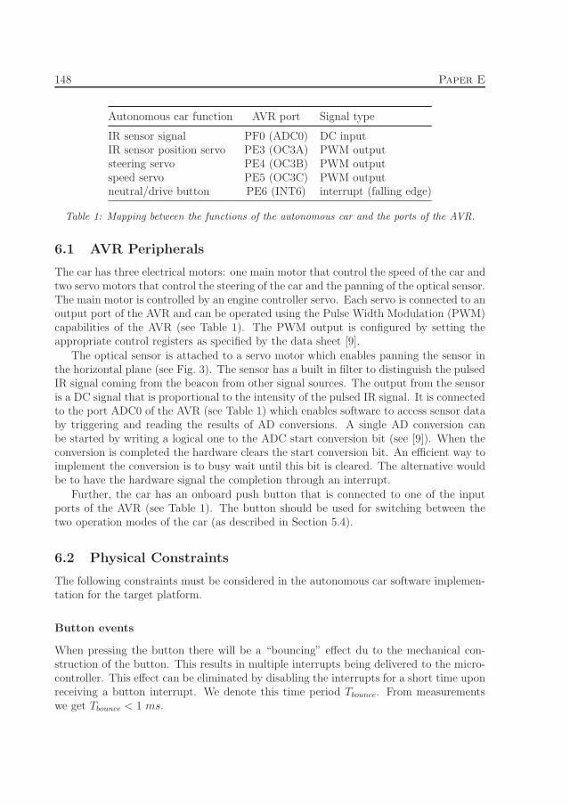
Autonomous car function AVR port Signal type
IR sensor signal PF0 (ADC0) DC inputIR sensor position servo PE3 (OC3A) PWM outputsteering servo PE4 (OC3B) PWM outputspeed servo PE5 (OC3C) PWM outputneutral/drive button PE6 (INT6) interrupt (falling edge)
Table 1: Mapping between the functions of the autonomous car and the ports of the AVR.
6.1 AVR Peripherals
The car has three electrical motors: one main motor that control the speed of the car andtwo servo motors that control the steering of the car and the panning of the optical sensor.The main motor is controlled by an engine controller servo. Each servo is connected to anoutput port of the AVR and can be operated using the Pulse Width Modulation (PWM)capabilities of the AVR (see Table 1). The PWM output is configured by setting theappropriate control registers as specified by the data sheet [9].
The optical sensor is attached to a servo motor which enables panning the sensor inthe horizontal plane (see Fig. 3). The sensor has a built in filter to distinguish the pulsedIR signal coming from the beacon from other signal sources. The output from the sensoris a DC signal that is proportional to the intensity of the pulsed IR signal. It is connectedto the port ADC0 of the AVR (see Table 1) which enables software to access sensor databy triggering and reading the results of AD conversions. A single AD conversion canbe started by writing a logical one to the ADC start conversion bit (see [9]). When theconversion is completed the hardware clears the start conversion bit. An efficient way toimplement the conversion is to busy wait until this bit is cleared. The alternative wouldbe to have the hardware signal the completion through an interrupt.
Further, the car has an onboard push button that is connected to one of the inputports of the AVR (see Table 1). The button should be used for switching between thetwo operation modes of the car (as described in Section 5.4).
6.2 Physical Constraints
The following constraints must be considered in the autonomous car software implemen-tation for the target platform.
Button events
When pressing the button there will be a “bouncing” effect du to the mechanical con-struction of the button. This results in multiple interrupts being delivered to the micro-controller. This effect can be eliminated by disabling the interrupts for a short time uponreceiving a button interrupt. We denote this time period Tbounce. From measurementswe get Tbounce < 1 ms.

7. Software Design for the Autonomous Car 149
Optical sensor
The protocol used for panning and reading the optical sensor is described next. Thepanning of the sensor is done by stepwise changing the sensor angle one degree at thetime and acquiring a sensor value after each move. There is a time period associatedwith moving the sensor one degree in either direction. We denote this time period Tmove.From measurements we get Tmove < 3 ms.
7 Software Design for the Autonomous Car
The software for the autonomous car was developed using the IDE described in Section 2.The IDE supports constructing software system models in a graphical environment andgenerating efficient C code from the model for execution on bare metal e.g. a microcon-troller. In this section we present the software model for the autonomous car and wedescribe the process of generating an executable from the tool.
7.1 Software Model
The goal of the software design process is to partition the functionality of the systeminto a hierarchical model using the CRC modeling constructs. In order for the modelto be able to interact with the environment it must also include environment interfaces.They provide an interface to the underlying target system (i.e. the microcontroller andits peripherals) and enables resource protection (a resource can only be accessed throughits environment interface). Hence, the environment interfaces disclose all the resourcesused by the software. The design process is described in detail in [1]. Next, we presentthe software model for the autonomous car that was developed using the aforementioneddesign process.
The model must specify one CRC as the root (by setting it as root in the configurationpane of the IDE) and this CRC alongside its content will be instantiated at run-time.The root CRC serves as the container for all the hierarchical CRC instance structures inthe model and it has no provided or required interface. Moreover, it encapsulates all theenvironment interfaces in the model. The environment interfaces defines the providedand required interface ports that provide access to specific services in the hardwareplatform (reading sensors, controlling motors etc.). The provided interface ports abstractshardware registers of the target platform and the required interface ports abstracts eventsthat originate in the target platform (e.g. the interrupt vector of the target platform mayinvoke a method in the model through the required interface port of the environmentinterface component as a reaction to a hardware interrupt). In order for the softwaresystem (i.e. CRC) to access a service (i.e. a set of registers) it must be linked with theprovided interface of the environment interface (by connecting the required interface ofthe CRC to the provided interface port of the environment interface).
The root CRC in the autonomous car model has the name autonomous car and its def-inition is depicted in Fig. 5. It defines three environment interfaces (env , timercounter3 ,

150 Paper E
Figure 5: The definition of the autonomous car CRC named autonomous car : the CRC in-stances in yellow (indicating that the CRC has no inner CRC instances) and blue (indicatingthat the CRC has inner CRC instances), and the environment interfaces in orange. The arrowsindicate message paths and the circles indicate access to environment interface registers.

7. Software Design for the Autonomous Car 151
Function type range unit
drivemode int 0 - 1 (no unit)sensor position int -80 - 80 (degrees)steering int -25 - 25 (degrees)speed int 0 - 6 (no unit)
Table 2: The representations for speed, steering, and sensor position used by the guidancesystem.
and adc) and instances thereof (env inst , tc3 inst , and adc inst). They act as abstrac-tions for the functions listed in Table 1.
The env inst provides access to the registers needed for configuring the PE6 portof the AVR to trigger interrupts when pressing the button on the car (the functionalityof specific ports of the AVR is described in [9]). Further, its required interface ports(startup int and button int) are used for delivering startup and button interrupt eventsoriginating in the environment. The startup events are handled by the startup handlerCRC (sh inst) who initializes all the CRCs in the model that have init methods and thenstarts the guidance system. The env controller CRC (env cntrl inst) is activated on thearrival of an interrupt from the button. The object takes care of filtering interrupts toeliminate the effects of “bouncing”, when a single press results in multiple interruptsdelivered to the interrupt port and it forwards the button press event to the guidancesystem CRC.
The tc3 inst provides access to the registers needed for configuring the PE3 , PE4 ,and PE5 ports of the AVR as PWM outputs and setting the output signals. The tc3controller CRC (tc3 cntrl inst) enable the guidance system to switch between the twodrive modes (neutral/drive) by disabling or enabling the PWM output signal using theData Direction Register for port E5 (setreg DDRE), to control the panning of the opticalsensor (setreg OCR3A), and to control the steering and speed of the car (setreg OCR3Band setreg OCR3C ). The guidance system uses an internal representation for the drive-mode, sensor position, steering, and speed values which simplifies its implementation (seeTable 2). The setreg methods of the tc3 controller CRC converts these values to their(hardware specific) PWM representations.
The adc inst provides access to the registers needed for configuring the PF0 port ofthe AVR as an analog input to the A/D converter and acquiring samples of the inputsignal. The initialization is managed by the adc controller CRC and its read ad methodis used for acquiring and delivering IR signal samples from the optical sensor.
The guidance system CRC (gs inst) enables target tracking and guidance based ondata from the optical sensor. It provides different services to its environment: startwhich is invoked automatically by the environment when the system has been initializedand toggle drivemode which enables the user to toggle the modes of operation for theautonomous car by pressing the push button on the car.
The definition of the guidance system CRC is depicted in Fig. 6. It encapsulates aninstance of the splitter CRC (splitter1 inst), guidance CRC (g inst) and targeting system

152 Paper E
Figure 6: The definition of the guidance system CRC: the provided/required interfaces of theguidance system CRC in white, the CRC instances in yellow (indicating that the CRC has noinner CRC instances) and blue (indicating that the CRC has inner CRC instances). The arrowsindicate message paths.
Figure 7: The definition of the targeting system CRC: the provided/required interfaces of thetargeting system CRC in white and the CRC instances in yellow (indicating that the CRC hasno inner CRC instances). The arrows indicate message paths.
CRC (ts inst). The splitter CRC forwards the events to its output ports. The guidanceCRC guides the car along a route in accordance with the routing strategy describedearlier (see Section 5). It controls the operation of the car (set steering and set speed)based on the location of the target relative the car (read distance and read heading).Moreover, it switches the drive mode (set drivemode) between neutral and drive uponinvocation of its toggle drivemode method. In case the target is out of sight the guidanceforces the car to drive in a small circle at low speed. The target data is provided by thetargeting system.
Fig. 7 depicts the CRC definition of the targeting system. It encapsulates instances ofthe splitter CRC (splitter2 inst and splitter3 inst), the panning controller CRC (pc inst),and the beacon detector CRC (bd inst). The panning controller is responsible for panningthe optical sensor from side to side by stepwise changing the sensor angle one degree atthe time. The angle change event is sent to the splitter which forwards the event tothe optical sensor as well as to the beacon detector. The beacon detector reacts to suchevents by investigating the sensor signal aiming to register the angles of the two columns.It samples the sensor signal and checks each sample to see if it is above a predetermined

7. Software Design for the Autonomous Car 153
threshold which indicates that the sensor is directed towards a column or towards a pointin between the columns. For every pan from one side to the other the beacon detectorregisters the first and the last angle for which the sensor value exceeds the threshold.From the registered angles it calculates the horizontal angle between the columns whichin turn is used to determine the distance to the target and the direction of the targetrelative to the car (see Section 5). When the target data changes it will notify the receiverthrough the event targetdata updated . Moreover, the beacon detector is notified whenthe sensor is at the edge of the panning cycle and it uses this information to identifythat the target is out of sight (no detection). The beacon detector automatically turnsthe direction of the panning (using the force turn method of the panning controller) ifno column edge is detected within 30 degrees from the latest column edge.
Next, we present the code for the CRC methods that define the functionality of thesoftware model.
7.2 CRC Code
This section presents the method code (C code) for each CRC in the system model for theautonomous car. The macros ASYNC and SYNC are used to encode messages. The firstparameter in the async and sync macros is the name of a port in the required interfaceand the last parameter is the argument to the receiving method. The two remainingparameters in the async macro is the baseline offset and the deadline (integers denotingtime); these parameters define the execution window for the receiving method. Thetiming specification for this model is described in detail in the next section (Section 7.3).
All variables that are not defined in the method in which they are used should beseen as state variables. State variables are defined in the state section of the CRC, thesame goes for constants (such as lookup tables etc.). However, since the state section isnot crucial for understanding the method code it is omitted in this presentation.
The method code of the startup handler CRC is presented below. Upon receivingthe startup event it first initializes all the objects connected to its init ports in the ordergiven by the method code. Then it starts the guidance system by sending a synchronousmessage via its required interface start .
startup handler CRCinit(){SYNC(init1);
SYNC(init2);
SYNC(init3);
SYNC(init4);
SYNC(start);
}
The method code of the env controller CRC is presented below. Its purpose is toeliminate the effect of bouncing (pressing the push button results in a burst of buttoninterrupts due to the effect of bouncing in the mechanical construction of the button).Upon receiving a button event to the method button int the env controller disables the

154 Paper E
button interrupts (by clearing a bit in one of the registers provided by env) and sendsa synchronous message via its required interface button press . Moreover, it makes surethat the button events will be enabled at a later time by sending a message to its methodenable with a delayed baseline. Note that the method enable is not part of the providedinterface of the button controller and can therefore only be invoked by the button con-troller itself.
env controller CRCinit(){PORTE |= (1<<PE6);
EIMSK |= (1<<INT6);
EICRB |= (1<<ISC61) | (1<<ISC60);
}button int(){EIMSK &= ∼(1<<INT6);
SYNC(button_press,NULL);
ASYNC(enable,BLO_ENABLE,DL_ENABLE,NULL);
}enable(){EIMSK |= (1<<INT6);
}
The tc3 controller has access to the registers associated with the timer/counter unit 3of the AVR (see [9]) and it controls the three PWM outputs (the PWM outputs are con-figured by the init method). It converts the values given as arguments to its methods (seeTable 2) and sets the PWM registers accordingly. The setreg OCR3A/B/C methods setsthe output to the sensor servo, steering servo, and the speed servo respectively and thesetreg DDRE sets the drive mode to neutral or drive. The method code is presented next.
tc3 controller CRCinit(){DDRE |= (0<<DDE3)|(0<<DDE4);
ICR3 = 0x4E20;
OCR3A = INIT_OCR3A;
OCR3B = INIT_OCR3B;
OCR3C = INIT_OCR3C;
TCCR3A |= (1<<COM3A1) | (1<<COM3B1) | (1<<COM3C1);
TCCR3B |= (1<<WGM33) | (1<<WGM32);
TCCR3A |= (1<<WGM31);
TCCR3B |= (1<<CS31);
}setreg DDRE(int arg){switch(arg){case NEUTRAL:
DDRE &= ∼(1<<DDE5);
break;
case DRIVE:
DDRE |= (1<<DDE5);
break;
}

7. Software Design for the Autonomous Car 155
}setreg OCR3A(signed int arg){int abs_angle = arg + MAX_SENSOR_ANGLE;
OC3A = (abs_angle << 2) + (abs_angle << 4) +
M + SENSOR_OFFSET;
}setreg OCR3B(signed int arg){int abs_angle = arg + MAX_STEERING_ANGLE;
OC3B = (abs_angle << 2) + (abs_angle << 4) +
M + STEERING_OFFSET;
}setreg OCR3C(int arg){switch(arg){case 0:
OCR3C = SPEED_0;
break;
case 1:
OCR3C = SPEED_1;
break;
case 2:
OCR3C = SPEED_2;
break;
case 3:
OCR3C = SPEED_3;
break;
case 4:
OCR3C = SPEED_4;
break;
case 5:
OCR3C = SPEED_5;
break;
case 6:
OCR3C = SPEED_6;
break;
}}
The method read ad of the adc controller CRC triggers a conversion and returns thevalue once the conversion is finished as presented next.
adc controller CRCinit(){ADMUX |= (1<<REFS1);
ADCSRA |= (1<<ADEN);
}read ad(){ADCSRA |= (1<<ADSC);
while(ADCSRA & (1<<ADSC));
return ADC;
}
The method code of the guidance CRC is presented below. It has two methods:

156 Paper E
10 9 8 7 6 5 4 3 2 10
1
2
3
4
5
6
7
Speed output value as a function of distance to the targetas provided by the array speed_arr[distance].
Distance to target in terms of anglebetween column edges (degrees).
spee
d =
sp
eed
_ar
r[d
ista
nce
] (n
o u
nit
)
Figure 8: The guidance CRC uses a lookup table (speed arr) to determine the speed outputvalue relative to the distance to the target. Note that no efforts have been taken to investigatethe performance of the car using different functions.
toggle drivemode that toggles the mode of operation (neutral or drive), and update outputthat calculates the speed and steering output values that control the servos of the au-tonomous car. When in the neutral mode the PWM output is disabled.
The speed and steering computations involves trigonometric functions as well as multi-plications and divisions. Performing these calculations in real-time on the microcontrollerconsumes an extensive amount of processing power. This can be avoided through the useof lookup tables. Lookup tables typically provide a mapping between function param-eters and precalculated function values. The guidance CRC defines two lookup tables.The array speed arr provides the speed output value as a function of the distance to thetarget (see Fig. 8). Note that the distance correspond to the horizontal angle between theIRED columns (δ). The array steering arr provides the steering output value (α) as afunction of the horizontal angle between the IRED columns (δ) and heading of the target(β) as defined by Eq. 2 (the constant a in Eq. 2 that represent the distance between thefront and rear axis of the car was set to 0.27 m based on manual measurements on the car).
guidance CRCinit(){drivemode = NEUTRAL;
}toggle_drivemode(){switch(drivemode){case NEUTRAL:
drivemode = DRIVE;
7. Software Design for the Autonomous Car 157
SYNC(set_drivemode,DRIVE)
break;
case DRIVE:
drivemode = NEUTRAL;
SYNC(set_drivemode,NEUTRAL)
break;
}}update_output(){int distance = SYNC(read_distance,NULL);
int heading = SYNC(read_heading,NULL);
if(distance > ARR_LENGTH){distance = ARR_LENGTH;
}switch(distance){case DISTANCE_UNKNOWN:
SYNC(set_speed,LOW_SPEED);
break;
default:
SYNC(set_speed,speed_arr[distance-1]);
break;
}switch(heading){case ON_TARGET:
SYNC(set_steering,CENTER);
break;
case HEADING_UNKNOWN:
SYNC(set_steering,MAX_LEFT);
break;
default:
if(heading > 0){SYNC(set_steering,
steering_arr[(heading-1)<<3][distance-1]);
}else{SYNC(set_steering,
-steering_arr[(-heading-1)<<3][distance-1]);
}break;
}}
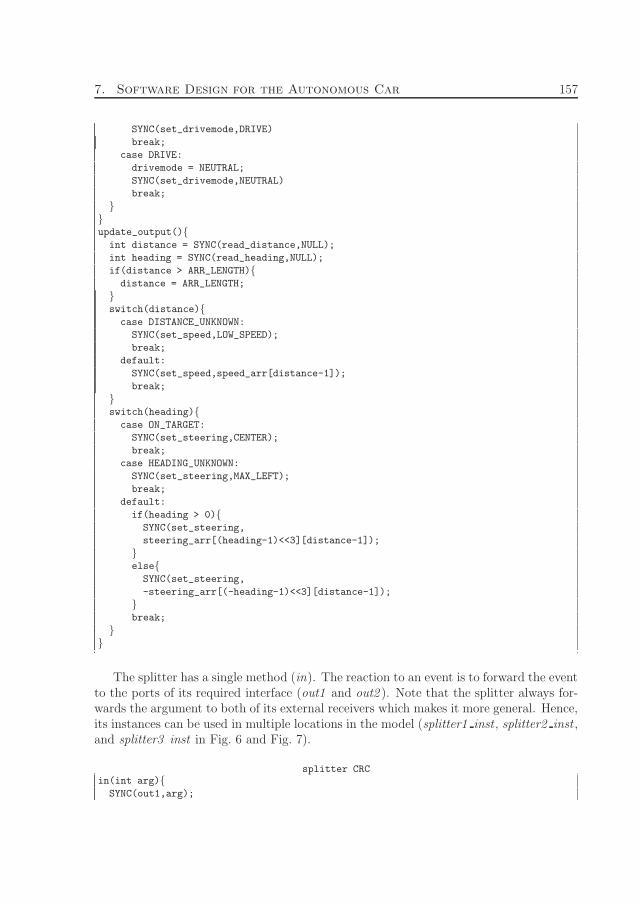
The splitter has a single method (in). The reaction to an event is to forward the eventto the ports of its required interface (out1 and out2 ). Note that the splitter always for-wards the argument to both of its external receivers which makes it more general. Hence,its instances can be used in multiple locations in the model (splitter1 inst , splitter2 inst ,and splitter3 inst in Fig. 6 and Fig. 7).
splitter CRCin(int arg){SYNC(out1,arg);

158 Paper E
SYNC(out2,arg);
}
The method code for the panning controller is presented below. Its purpose isto control the panning of the optical sensor. The method pan increases or decreasesthe angle based on the panning direction (dir) and sends it to the optical sensor(SYNC (sensor angle, angle)). The pan method contains an asynchronous call to it-self which makes this a continuous process and the frequency is defined by the baselineoffset (BLOPAN). The timing specification is presented in detail in the next section(Section 7.3). The pan method is not exposed in the provided interface of the panningcontroller CRC so the only way to start the panning process is to invoke the method start .The methods force turn and curr angle switches the panning direction and returns thecurrent angle respectively.
panning controller CRCinit(){dir = RIGHT;
angle = LEFT_EDGE;
}start(){ASYNC(pan,BLO_PANSTART,DL_PANSTART,NULL);
}force_turn(){switch(dir){case LEFT:
dir = RIGHT;
break;
case RIGHT:
dir = LEFT;
break;
}}pan(){ASYNC(pan,BLO_PAN,DL_PAN,NULL);
switch(dir){case LEFT:
if(angle == LEFT_EDGE){dir = RIGHT;
SYNC(edge_reached,NULL);
}else{
angle--;
}break;
case RIGHT:
if(angle == RIGHT_EDGE){dir = LEFT;
SYNC(edge_reached,NULL);
}else{
angle++;
7. Software Design for the Autonomous Car 159
}break;
}SYNC(sensor_angle,angle);
}
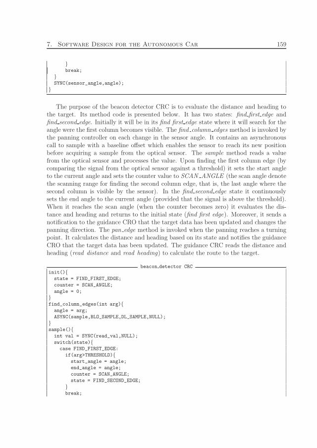
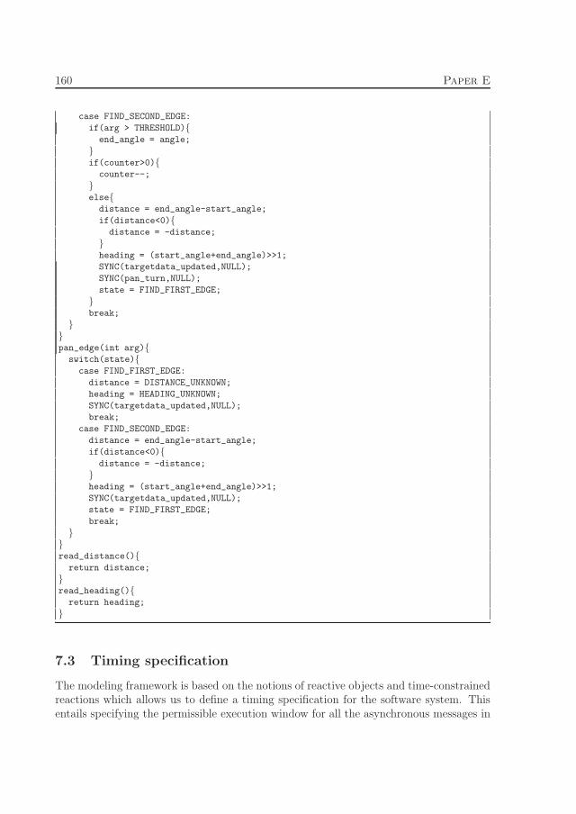
The purpose of the beacon detector CRC is to evaluate the distance and heading tothe target. Its method code is presented below. It has two states: find first edge andfind second edge. Initially it will be in its find first edge state where it will search for theangle were the first column becomes visible. The find column edges method is invoked bythe panning controller on each change in the sensor angle. It contains an asynchronouscall to sample with a baseline offset which enables the sensor to reach its new positionbefore acquiring a sample from the optical sensor. The sample method reads a valuefrom the optical sensor and processes the value. Upon finding the first column edge (bycomparing the signal from the optical sensor against a threshold) it sets the start angleto the current angle and sets the counter value to SCAN ANGLE (the scan angle denotethe scanning range for finding the second column edge, that is, the last angle where thesecond column is visible by the sensor). In the find second edge state it continuouslysets the end angle to the current angle (provided that the signal is above the threshold).When it reaches the scan angle (when the counter becomes zero) it evaluates the dis-tance and heading and returns to the initial state (find first edge). Moreover, it sends anotification to the guidance CRO that the target data has been updated and changes thepanning direction. The pan edge method is invoked when the panning reaches a turningpoint. It calculates the distance and heading based on its state and notifies the guidanceCRO that the target data has been updated. The guidance CRC reads the distance andheading (read distance and read heading) to calculate the route to the target.
beacon detector CRCinit(){state = FIND_FIRST_EDGE;
counter = SCAN_ANGLE;
angle = 0;
}find_column_edges(int arg){angle = arg;
ASYNC(sample,BLO_SAMPLE,DL_SAMPLE,NULL);
}sample(){int val = SYNC(read_val,NULL);
switch(state){case FIND_FIRST_EDGE:
if(arg>THRESHOLD){start_angle = angle;
end_angle = angle;
counter = SCAN_ANGLE;
state = FIND_SECOND_EDGE;
}break;
160 Paper E
case FIND_SECOND_EDGE:
if(arg > THRESHOLD){end_angle = angle;
}if(counter>0){
counter--;
}else{
distance = end_angle-start_angle;
if(distance<0){distance = -distance;
}heading = (start_angle+end_angle)>>1;
SYNC(targetdata_updated,NULL);
SYNC(pan_turn,NULL);
state = FIND_FIRST_EDGE;
}break;
}}pan_edge(int arg){switch(state){case FIND_FIRST_EDGE:
distance = DISTANCE_UNKNOWN;
heading = HEADING_UNKNOWN;
SYNC(targetdata_updated,NULL);
break;
case FIND_SECOND_EDGE:
distance = end_angle-start_angle;
if(distance<0){distance = -distance;
}heading = (start_angle+end_angle)>>1;
SYNC(targetdata_updated,NULL);
state = FIND_FIRST_EDGE;
break;
}}read_distance(){return distance;
}read_heading(){return heading;
}
7.3 Timing specification
The modeling framework is based on the notions of reactive objects and time-constrainedreactions which allows us to define a timing specification for the software system. Thisentails specifying the permissible execution window for all the asynchronous messages in

7. Software Design for the Autonomous Car 161
Name Value (ms)
BLOenable 1DLenable 0.1BLOpanstart 0DLpanstart 0.1BLOpan 3.2DLpan 0.1BLOsample 3.1DLsample 0.1
Table 3: The timing specification for the autonomous car in terms of baseline offsets and relativedeadlines for the asynchronous method calls.
the code (the synchronous messages always inherits the caller’s time constraints). Thetiming specification is preserved throughout the design process and is utilized by thescheduler at run-time. However, without knowing the worst case execution time for allthe methods in the system it is not possible to guarantee that the timing behavior thatfollow from executing the software will conform to the specification. Still, as long asthe processor can execute the method code within the specified deadline for the methodthe timing specification will be met. Since none of the methods contain any demandingcomputations (recall the lookup tables described in the previous section) it should besafe to set the deadlines for every asynchronous method to 0, 1 ms. The complete timingspecification for the autonomous car is presented in Table 3.
Button interrupts are delivered to the button int method which immediately disablesthe button interrupts. We want the bouncing effect to end before we enable the interruptsagain and therefore we set BLOenable = 1 ms (from Section 6.2 we know that Tbounce <1 ms).
In the start method of the panning controller we want the pan process to start im-mediately. This is achieved by setting the baseline offset to zero (BLOpanstart = 0).
The behavior of the car rely on the number of route updates that is generated asthe car approaches the target (a faster panning of the sensor increases the chance ofcolumn detections which results in supplementary route updates). The panning of theoptical sensor is managed by the method pan in the panning controller. It contains anasynchronous call to itself which makes this process continuous and the period time isdefined by the baseline offset BLOpan. We want to set the period time of the panningprocess as low as possible while allowing for the servo to reach its new position beforethe next position change. However, since the signal of the sensor is sampled in thebeacon detector we must examine the timing characteristics of the whole reaction chainin order to determine the shortest possible period time of the panning process. The timingcharacteristics for the panning process are shown in Figure 9. It illustrates the permissibleexecution windows for the reactions alongside physical constraints of the target platform(Section 6.2) that must be met in order to achieve a proper system behavior. From the

162 Paper E
������������� ������
�� ��� ��
�� ��
������ ����
��
�� �� �
���� ��������� ������
����
������������ ��������� ����
���
��
Figure 9: The timing characteristics of the panning process in terms of baseline offsets anddeadlines for the permissible execution windows of the asynchronous methods (pan and sample)alongside the physical constraint of the target platform (Tmove). Setting BLOsample ≥ DLpan +
Tmove assures that the sensor has reached its new position before issuing an AD conversion(read val). The period time of the panning process (BLOpan) is defined by BLOsample andDLsample.
figure we get the following equations.
BLOpan ≥ BLOsample +DLsample (3)
BLOsample ≥ DLpan + Tmove (4)
Accordingly, the period time for the panning process becomes BLOpan = 3.2 ms.
8 Program analysis
The system design contains all information required to perform timing analysis on thesystem, except the WCET’s on each distinct method. The tool automatically gives usinterrival-time and offset information for each task (but only for systems with a ”simple”program flow [10]).
8.1 WCET estimation
In this case we have adopted a straight forward approach on finding the WCET’s for eachfunction. For each method (m) the tool generates testcode that executes the method(m) and measures the executiontime. All internal (in the method (m)) method calls(SYNC’s) and message passing (ASYNC’s) are replaced with call to a empty function. Fordata dependent operations the programmer must manually specify object state, methodparameters and method call return values for the WCET measurement to be accurate.For this analysis to be correct the program code must remain unchanged and must befrom the same compilation. So instead of recompiling the program we link the programdifferently when performing the WCET measurement. Effects of caches and pipeliningare not an issue on the AVR platform.

9. Conclusion 163
8.2 Scheduler
The scheduler used is a non-preemptive DM scheduler, hence maximum blocking for atask is the maximum WCET of all other lower priority tasks in the system tasks in thesystem Using a more advanced scheduler (such as a preemptive SRP scheduler) wouldreduce the blocking-time of sample and pan, but is not required in this case for the systemto be schedulable.
8.3 The numbers
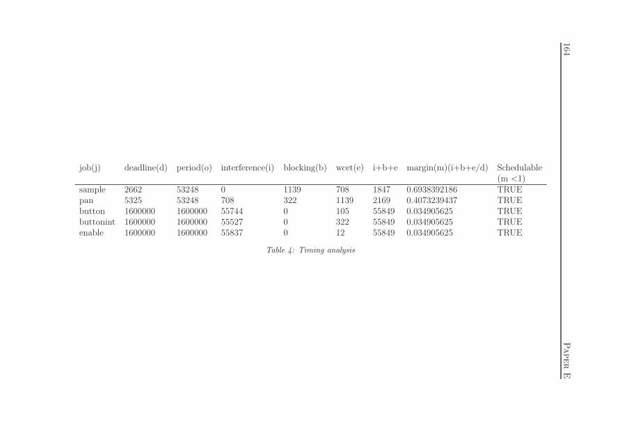
Job(j) is the first method called in an ASYNC call. Interference(i) is defined as thetime a higher or same priority task might prevent (j) from starting execution. (Here wehave to take into account the periods, higher priority task might have to be accountedmort than once) Blocking(b) is the maximum time a lower priority task might prevent(j) from starting execution. (This is MAX( job i = all jobs, dl(i)>dl(j))) For a job to beschedulable the time i+b+e of a job j must be less than the deadline of j.
The first step in performing timing analysis is to check the total utilization (this is arequired condition). In this case the utilization can be calculated as:(708+1139)/52248+ (105+322+12)/1600000 = 0.036 < 1, so this condition holds witha good margin.
Checking utilization is not sufficient for a system with shared resources or whendeadline != interrarivaltime. A sufficient condition is to check that each job is schedulable,this can be achieved using standard scheduling theory. The table (4) shows that thiscondition holds (m < 1 for all jobs).
8.4 Future work on analysis
Implementing other more advanced schedulingtests (e.g. offset, memory analysis) isfeasable since the tool gives us all the necessary information. (WCET, time offset in-formation between tasks) and by using a late version of GCC (>=4.6) we will also getstack usage per function. Moreover, the tool also facilitates using SRP as scheduler, andcan generate preemption levels and perform analysis [11]. Using SRP fits nicely with ourmodel since locking is inherently hierarchical by using the SYNC primitive.
9 Conclusion
This paper shows how to design the software for an autonomous car using an integrateddevelopment environment (IDE). The IDE enforces a static component and communi-cation structure, reflecting the concurrent behavior of the system. System models areconstructed by composing components into hierarchical system models based on the sys-tem’s interaction with its environment. In particular, the system models are constructedgraphically which supports understanding of complex models. Further, the IDE facili-tates static analysis and generation of memory- and cpu-efficient executables.
164PaperE
job(j) deadline(d) period(o) interference(i) blocking(b) wcet(e) i+b+e margin(m)(i+b+e/d) Schedulable(m <1)
sample 2662 53248 0 1139 708 1847 0.6938392186 TRUEpan 5325 53248 708 322 1139 2169 0.4073239437 TRUEbutton 1600000 1600000 55744 0 105 55849 0.034905625 TRUEbuttonint 1600000 1600000 55527 0 322 55849 0.034905625 TRUEenable 1600000 1600000 55837 0 12 55849 0.034905625 TRUE
Table 4: Timing analysis

References 165
The software for the autonomous car was constructed and integrated into the targetplatform. The result is a working prototype that operate according to its specification.That is, the car drives autonomously from the starting line to the beacon and stops infront of the beacon as intended.
This paper also show how the system’s timing properties can be analyzed in theIDE using standard scheduling theorems and machine assisted WCET measurements.Analyzing the timing properties for this use case confirm that they will always hold.
To conclude, this paper demonstrates the applicability of the software design method-ology in developing real-time software for resource-constrained systems using the IDE.
Acknowledgment
This work was supported in part by the Knowledge Foundation in Sweden under aresearch grant for the SAVE-IT project, the EU Interreg IV A North Programme(grant no. 304-15591-08), the ESIS project (European Regional Development Fund, grantno. 41732), and the EU AESOP project.
References
[1] J. Wiklander, J. Eliasson, A. Kruglyak, P. Lindgren, and J. Nordlander, “Enablingcomponent-based design for embedded real-time software,” Journal of Computers(JCP), vol. 4, no. 12, pp. 1309–1321, 2009.
[2] J. Wiklander, J. Eriksson, and P. Lindgren, “An IDE for component-based designof embedded real-time software,” in Industrial Embedded Systems (SIES), 2011 6thIEEE International Symposium on, june 2011, pp. 47 –50.
[3] J. Nordlander, M. P. Jones, M. Carlsson, R. B. Kieburtz, and A. Black, “Reac-tive objects,” in Fifth IEEE Int. Symp. on Object-Oriented Real-Time DistributedComputing (ISORC), 2002, pp. 155–158.
[4] J. Nordlander, M. P. Jones, M. Carlsson, and J. Jonsson, “Programming withtime-constrained reactions,” Lulea University of Technology, Tech. Rep., 2005.[Online]. Available: http://pure.ltu.se/ws/fbspretrieve/441200
[5] P. Levis et al., “TinyOS: An operating system for sensor networks,” in AmbientIntelligence. Springer Verlag, 2004.
[6] K. Hanninen, J. Maki-Turja, M. Nolin, M. Lindberg, J. Lundback, and K.-L.Lundback, “The Rubus component model for resource constrained real-time sys-tems,” in 3rd IEEE Int. Symp. on Industrial Embedded Systems, June 2008, pp.177–183.

166
[7] S. Mubeen, J. Maki-Turja, M. Sjodin, and J. Carlson, “Analyzable modelingof legacy communication in component-based distributed embedded systems,” in37th EUROMICRO Conference on Software Engineering and Advanced Applications(SEAA 2011). IEEE, August 2011, p. 10.
[8] T. Hofmeijer, S. Dulman, P. Jansen, and P. Havinga, “AmbientRT - real time systemsoftware support for data centric sensor networks,” in Intelligent Sensors, SensorNetworks and Information Processing Conference, 2004. Proceedings of the 2004,dec. 2004, pp. 61 – 66.
[9] AVR AT90CAN128 data sheet. (webpage) Last accessed 20110911. [Online].Available: http://www.atmel.com/dyn/resources/prod documents/doc4250.pdf
[10] J. Eriksson, J. Wiklander, S. Aittamaa, P. Pietrzak, and P. Lindgren, “Srp-dmscheduling of component-based embedded real-time software,” in WORDS 2011,Malardalen Hogskola, Sweden, jun 2011.
[11] T. Baker, “A stack-based resource allocation policy for realtime processes,” in Real-Time Systems Symposium, 1990. Proceedings., 11th, dec 1990, pp. 191 –200.


![NOF Clinicians Guide[1]](https://static.fdocuments.net/doc/165x107/577d2a461a28ab4e1ea8d8a8/nof-clinicians-guide1.jpg)