Twin Direct Recording Channel - Millennia Media, Inc
19
Twin Direct Millennia Music & Media Systems TD-1 Twin Direct Recording Channel Instruction Manual © 2007, Millennia Media, Inc. 032107 All rights reserved. Printed in the USA
Transcript of Twin Direct Recording Channel - Millennia Media, Inc
Twin Direct
�
MillenniaMusic & Media Systems
TD-1Twin Direct
Recording Channel
Instruction Manual
© 2007, Millennia Media, Inc. 032107All rights reserved. Printed in the USA

TD-� MillenniaMusic & Media Systems Twin Direct
�
MillenniaMusic & Media Systems
�
TABLE OF CONTENTS
GOVERNMENTAL NOTICES 4
INSPECTION 7
SAFETY PRECAUTIONS 9
DESIGN CRITERIA 11
QUICK START 12
FRONT PANEL FUNCTIONS
Input Section 13
Equalizer Section 17
Routing Section 19
REAR PANEL FUNCTIONS 20
SIGNAL FLOW DIAGRAM 26
GROUND LIFTING & ISOLATION 28
JUMPER MAPS 29
ASSEMBLY INSTRUCTIONS (Rack Mount, etc..) 31
PERFORMANCE GRAPHS 33
SPECIFICATIONS 36
CONTACT INFORMATION Back Cover
ONE YEAR WARRANTY
Millennia Media will repair this product, free of charge, in the USA, in the event of defect of materials or workmanship for one (1) year following date of purchase. This warranty is extended only to the original purchas-er. This limited warranty covers failures due only to defects in materials and workmanship that occur during normal, intended use and does not cover damage which occurs in shipment or failures which are caused by products not supplied by Millennia. This limited warranty does not cover failures which arise from accident, misuse, abuse, neglect, mishandling, misapplication, faulty installation, improper adjustment, alteration or modification of product, incompatibilities, line-power surges, acts of God, or service performed by anyone other than Millennia or its authorized agent. Vacuum tube failures are not covered under warranty.
LIMITS AND EXCLUSIONS
There are no express warranties except as listed above. Millennia shall not be liable for special, subsequent, incidental, consequential, or punitive damages, including, but not limited to: damage to recordings, broadcasts, microphones, mixing consoles, or any associated equip-ment, downtime costs, loss of goodwill, or claims of any party dealing with purchaser for such damages resulting from the use of this product. All warranties, express and implied, including the warranties of merchant-ability and fitness for a particular purpose are limited to the applicable warranty period set forth above.
Some states do not allow the exclusion or limitation of incidental or consequential damages, or length of time an implied warranty remains in effect. As such, the above exclusions may not apply. This warranty gives you specific legal rights and you may also have other rights which can vary from state to state.
REAMP® is a registered U.S. trademark. REAMP technology is used under license -- U.S. Pat no. 6,005,950.

TD-� MillenniaMusic & Media Systems Twin Direct
�
MillenniaMusic & Media Systems
�
FCC NOTICEINFORMATION FOR THE USER
This equipment has been tested and found to comply with the limits for a Class B digital device, pursuant to Part 15 of the FCC Rules. These limits are designed to provide reasonable protection against harmful interference in a residential installation. This equipment generates, uses and can radiate radio frequency energy and, if not installed and used in accordance with the instructions, may cause harmful interference to radio communications. However, there is no guarantee that interference will not occur in a particular installation. If this equipment does cause harmful interference to radio or television reception, which can be determined by turning the equipment off and on, the user is encouraged to try to correct the interference by one or more of the following measures:
1) Reorient or relocate the receiving antenna2) Increase the separation between the equipment and receiver3) Connect the equipment into an outlet on a circuit different from that to which the receiver is connected.4) Consult the dealer of an experienced radio/TV technician for help.
The user may find the following publication prepared by the Federal Communications Commission helpful:
“How to Identify and Resolve Radio-TV Interference Problems” (Stock Number 004-000-00345-4)
Available exclusively from the Superintendent of Documents, Govern-ment Printing Office, Washington, DC 20402 (telephone 202-512-1800)
FCC WARNING
Changes or modifications not expressly approved by the party respon-sible for compliance to Part 15 of the FCC Rules could void the user’s authority to operate the equipment.
This device complies with Part 15 of the FCC Rules. Operation is subject to the following two conditions: (1) This device may not cause harmful interference, and (2) This device must accept any interference received, including interference that may cause undesired operation. This Product Certified to meet the Standards in the categories: Audio/Video and Musi-cal Instrument Apparatus for Household, Commercial, and Similar Gen-eral Use EMI: FCC Part 15 Class B; ICAN ICES-003 Class B; EN55022 Class B
CE NOTICEINFORMATION FOR THE USER
This equipment has been tested and found to comply with the limits for a Class B or Class 2 digital device, pursuant to EN 55022 Rules. These limits are designed to provide reasonable protection against harmful in-terference when the equipment is operated in a commercial environment. This equipment generates, uses, and can radiate radio frequency energy and, if not installed and used in accordance with the instruction manual, may cause harmful interference to radio communications. Operation of this equipment in a residential area is likely to cause harmful interference in which case the user will be required to correct the interference at his own expense.
The user may find the following publication prepared by the Federal Communications Commission helpful:
“How to Identify and Resolve Radio-TV Interference Problems” (Stock Number 004-000-00345-4)
Available exclusively from the Superintendent of Documents, Govern-ment Printing Office, Washington, DC 20402 (telephone 202-512-1800
WARNING
Changes or modifications not expressly approved by the party respon-sible for compliance to EN 55022 Rules could void the user’s authority to operate the equipment.
I

TD-� MillenniaMusic & Media Systems Twin Direct
�
MillenniaMusic & Media Systems
�
INSPECTION
Congratulations on your purchase of the Millennia TD-1 TWIN DIRECT recording channel. TD-1 is the culmination of meticulous listening tests on innumerable circuit, topology, and packaging designs over decades of audio product development experience. Your TD-1 is a finely tuned instrument intended for critical professional applications — with the added benefits of selectable vacuum tube DI amplifier, all discrete FET solid state DI amplifier, variable input impedances, Speaker Soak(tm), and REAMP®, we feel it offers the world’s best sounding and most sonically versatile DI + recording path. With the emergence of 24+ bit digital audio, recording engineers are faced with a new requirement for undistorted dynamic range. Twin Direct meets this challenge exceptionally well. NOTE: Any changes or modifications not expressly approved by MIL-LENNIA MEDIA, INC. (Millennia) could void your authority to operate this equipment under the EC, ICAN, or FCC rules.
1. Copyright: You acknowledge that no title to the intellectual property in the TD-1 is transferred to you.
2. Inspection: Inspect packing box(es), TD-1, and cable(s) for damage, unusual marks, or shortages. It is your responsibility to report damage, shortage, or mis-shipments in a timely manner. Millennia and/or its deal-ers will not be responsible for claims arising from damage in shipping, nor will claims for shortage or mis-shipments be honored, more than 10 days after ship date.
3. Read this manual carefully and completely before attempting to use the TD-1. Improper operation could result in damage to product. It is the user’s responsibility to understand the safe use and operation of this device.
4. The shipping box of the TD-1 system will include (1) Owner’s Manual, (2) TD-1, (3) a UL approved power cord (110 V countries only), (4) Own-er’s Registration Card, (5) Four rubber feet with mounting hardware, and (6) Steel carrying handle with mounting hardware. Fill out the Owner’s Registration Card and return to Millennia at your earliest ability or register on line at www.mil-media.com.
The material contained in this manual consists of information that is prop-erty of Millennia and is intended solely for use by the purchasers of the equipment described in this manual. Without express written permission,
CAN Class B Digital Equipment
This Class B apparatus meets all requirements of the Canadian Interfer-ence-Causing Equipment Regulations.
Cet appareil numérique de la classe B respecte toutes les exigences due Reglement sur le materiel brouilleur du Canada
BZT Declaration (German)
Bescheinigung de Millennia Media, Inc. hiermit wird bescheinigt, dass die Direct Box TD-1 “TWIN DIRECT” in Übereinstimmung mit den Bestimmun-gen der VFG 523/1969, DIN 57871 / VDE 0871 / 09.84, und DIN 75875 Part 1 A2 / 10.90 (Amtsblattvertugung) funk-entstört ist.
Der Deutshchen Bundespost wurde das Inverkehrbringen dieses Gerats angezeight und die Berechtigung zur Überprüfung der Serie auf Einhaltung der Bestimmungen eingeräumt.
Einhaltung mit betreffenden Bestimmungen kommt darauf an, dass ge-schirmte Ausführungen gebraucht werden. Für die Beschaffung richtiger Ausführungen ist der Betreiber Verantwortluich.
Dieses Gerät wurde sowohl einzelnals auch in einer Anlage, die einen normalen Anwendungsfall nachbildet, auf die Einhaltung der Funkent-störbestimmungen gerprüft. Es ist jedoch möglich, dass die Funkentstör-bestimmungenunter Ungunstigen Umständen bei anderen Gerätekombi-nationen nicht Eingehalten werden. Der Betreiber ist für die Einhaltung der funkeutstörungsbestimmungen seiner gesamten Anlage verantwortlich, in der dieses Gerät betrieben wird.
Millennia Media, Inc.

TD-� MillenniaMusic & Media Systems Twin Direct
�
MillenniaMusic & Media Systems
�
SAFETY PRECAUTIONS
For your safety and the safety of others, be sure to read and understand all safety and operational instructions before attempting to use the TD-1.
WARNING: The TD-1 internal circuitry carries lethal voltages. Carefully observe all warnings, precautions, and instructions on the TD-1 and as described in the instructions supplied with the unit.
1. WATER, MOISTURE, AND SPILLAGEDo not attempt to use the TD-1 in, near, or around water or in unusually moist environments, such as near a sink or swimming pool. Prevent liquids or any other materials or objects from spilling or falling into the TD-1 unit.
2. HEAT AND VENTILATION Be sure to allow adequate ventilation to TD-1 and avoid using or installing unit in close proximity to heat sources, such as heaters, stoves, radiators, power amplifiers, spotlights, or other heat-producing appliances or equip-ment.
3. POWER SOURCES AND POWER CORD PROTECTIONThe TD-1 Power Supply should be connected to a power source only of the type described in the operating instructions or as marked on the Power Sup-ply. Route the power cord so that it is not likely to be walked on or pinched by having objects placed on it. Pay particular attention to plugs, receptacles, and the point where the AC power cord exits the TD-1.
4. GROUNDINGFor your safety, it is extremely important that the grounding pin of the 3-wire power cable (included with unit) be inserted into a grounding type 3-pin power outlet. If you are unable to insert the plug into an existing outlet, contact an electrician to install a properly grounded 3-pin power outlet, preferably that with OFI / CFI protection, if available.
5. DAMAGE REQUIRING SERVICEThis unit should be repaired or serviced by qualified personnel whenever:· The AC power cord has been damaged, or· Objects have fallen or liquid has spilled into any TD-1 unit, or· The unit does not function properly or exhibits a marked change in per-
formance, or· The unit has been abused, dropped, or damaged, or· The unit has been exposed to rain or moisture
Millennia prohibits the duplication of any portion of this manual or the use thereof for any purpose other than the operation and/or maintenance of the equipment described in this manual. This manual may not be dupli-cated in whole or in part without the written consent of Millennia.
TD-1, TWIN DIRECT, Speaker Soak, and Twin Topology are trademarks of Millennia Media, Inc. All other trademarks are property of their respec-tive holders. TD-1 serial number is located on the rear left side of each unit. We suggest that you record the serial number in the space provided below. Refer to it whenever you call an authorized Millennia repair facility or the manufacturer. Make sure that you return your completed warranty card immediately.
Features and specifications subject to change without notice.© 2003 - Millennia Media, Inc., All rights reserved
Serial No. __________________________________________________
Purchase Date ______________________________________________
Where Purchased ___________________________________________

TD-� MillenniaMusic & Media Systems Twin Direct
��
MillenniaMusic & Media Systems
10
seconds for the phantom power to fully “ramp down” before inserting or removing a microphone. This is good advice for protecting your micro-phone investments, as well.
DESIGN
The TD-1 TWIN DIRECT is a collection of core Millennia products de-signed into a sophisticated recording channel + direct box. We believe TD-1 is the world’s most versatile and absolutely best sounding DI (direct injection) box. TD-1 offers numerous signal path topologies (vacuum tube, discrete transistors, monolithics, three different audio transformers, speaker soak, REAMPs, etc.) all sonically optimized to their respective strengths.
TD-1 offers Twin Topology DI input stages which can be switched to employ high voltage vacuum tube (12AT7) -or- 100% discrete transis-tor (J-FET) amplifiers. The user may also select low, medium, or high input impedance on both input topologies, making TWIN DIRECT the most versatile DI available. The TD-1 also offers two bands of Millennia’s acclaimed NSEQ-2 fully parametric equalization, used by top mastering facilities around the globe, fully sweepable from 20 Hz to 25 kHz. The NSEQ-2 bands are provided for high-resolution audio sculpting of instru-ments such as guitar, bass and keyboard, or artistic and corrective work — adding “air” and “punch,” removing “mud,” and so forth — all with the natural, artifact-free audio qualities NSEQ is known for. Numerous func-tions and routing paths are available, as noted by name:
1.) HV-3 discrete hybrid solid state microphone preamplifier2.) STT-1 ORIGIN vacuum tube DI Input with selectable impedances3.) Class-A biased discrete J-FET DI input with selectable impedances4.) NSEQ-2 dual band fully parametric equalizer, 20 Hz - 25 kHz5.) Patented REAMP® dual guitar simulation outputs (Strat & Les Paul)6.) Numerous Ground-Lift and Ground-Isolation switches and jumpers7.) SPEAKER SOAK(tm) guitar amplifier Input Selection8.) Audiophile-grade headphone output with level adjustment9.) Class-A biased discrete solid-state FET output stage10.) High performance DIT-01 output transformer, 3 Hz - 300 kHz
6. SERVICINGLethal voltages are found inside the TD-1 chassis. The user should not attempt to repair or service this unit. All servicing and/or repairs should be referred to Millennia.
If, after reading all instructions, precautions, and warnings, you have re-maining questions, please contact Millennia directly before attempting to use your TD-1. Retain this owner’s manual as a record of your purchase to aid positive identification in the event of loss.
Before connecting power to the TD-1, assure that the rear panel voltage selection fuse block switch is set correctly. In the USA or Japan, TD-1 is shipped with the voltage selection block set to 100-120 VAC. If you change the voltage selection block to 200-240 VAC usage, be sure to change both fuses to the correct types. See “Rear Panel” instructions for proper fuse requirements.
The TD-1 enclosure measures approximately 8.5” wide x 3.5” high x 13.5” deep and is designed for mounting (in pairs) into a standard 2U, 19” equipment rack. If the TD-1 is mounted in a road case or other rack which is prone to strong vibration or shock, it is highly recommended that the rear of the TD-1 be supported or otherwise reinforced to withstand such conditions. TD-1 contains high voltage vacuum tube and discrete transistors, many running in Class-A bias. As such, the TD-1 TWIN DI-RECT runs quite warm and should be mounted for proper ventilation with at least one rack screw space open above and below the unit.
TD-1 is designed on a common ground topology. For high quality opera-tion, and for your own safety and the safety of others, do not defeat the power cord earth grounding pin. If required, earth ground can be lifted safely via built-in switching, described later.
TD-1 FRONT-END PROTECTION: Millennia Music & Media Systems enjoys a reputation for what many top engineers and producers call the world’s most musically accurate and dynamically uniform microphone preamplifier — the HV-3. But this thoroughbred design is not achieved without certain operating criteria. Back-to-back Zener diodes protect the super-matched discrete bipolar input transistors against high transient energy spikes common when inserting and extracting XLR connectors. To maintain top performance and protect the TD-1’s sensitive HV-3 front-end, it is advised that you do not insert or extract XLR connectors with power on. Get in the habit of disabling AC power and waiting about ten

TD-� MillenniaMusic & Media Systems Twin Direct
��
MillenniaMusic & Media Systems
1�
a discrete-hybrid balanced receiver with +45 dB of gain. Instrument (DI) input is routed via TT switch to a vacuum tube buffer amplifier or discrete solid state (FET) buffer amplifier, with triple input impedance selection switching on both topologies. Any input may be attenuated via a -20 dB pad switch. The DI input also offers a selectable guitar amplifier Speaker Soaktm input and selectable buffered or unbuffered “direct DI through” output. All inputs are followed by two bands of NSEQ-2 fully parametric Eq stages (20 Hz – 25 kHz). Numerous routing, output, and grounding op-tions round out the world’s most versatile and best sounding “direct box.”
FRONT PANEL — INPUT SECTION —
INSTRUMENT DI / SPEAKER SOAKtm INPUT ¼” Unbal Phone JackThe heart of TWIN DIRECT. A normalled ¼” mono Phone Jack which accepts any unbalanced source, such as MIDI instrument (keyboard, sampler, etc..), electric guitar, electric bass, piezoelectric acoustic guitar pickup, etc.. This DI (Direct Inject) input will accept virtually any known DI signal level, from very low output passive sources, to high output (>15 Volts RMS) active sources. This input is also designed to accept direct feed from a power amplifier, such as a guitar amp (see “Speaker Soak” switch, below).
Most keyboards and MIDI instruments have electrically buffered outputs exhibiting very low output impedance, generally under 150 ohms. On the other hand, passive electric guitar pickups exhibit significantly higher out-put impedance. To properly “couple” this diversity of instruments in the most musically pleasing manner, TWIN DIRECT offers three different in-put impedance settings that will help an artist “fine tune” the musicality of any instrument, pickup, or program. Each time you try a new instrument or MIDI device with the TWIN DIRECT, be sure to experiment with differ-ent topologies and input impedances to find the ideal sonic performance (see “Twin Topology” and “Impedance Select” below). There is no inher-ently “right” setting — use your ears and production goals to determine the best impedance bridge and input topology.
TWIN DIRECT’s dual DI amplifiers offer rich musical variation with electric instruments — vacuum tube amplifiers are well known to “couple” electric guitar and bass pickups differently than solid-state amplifiers. Vacuum tubes offer a unique “sound” that solid-state doesn’t, and visa versa. Each amplifier topology offers complimentary sonic performance to the other, and both are widely used in professional recording and stage work. Taking full advantage of this sonic duality, TWIN DIRECT
TWIN DIRECT has four available audio inputs:
1.) Line Input (XLR, front panel)2.) HV–3 Mic Preamp Input (XLR, rear panel)3.) DI Instrument Input (1/4” phone, front panel)4.) Amplifier / Speaker Soak Input (1/4” phone, front panel)
TWIN DIRECT has nine different rear-panel audio outputs:
1.) REAMP® Les Paultm Guitar Simulation Output (1/4” phone)2.) REAMP® Stratocastertm Guitar Simulation Output (1/4” phone)3.) Balanced Line Level Output (XLR)4.) Balanced Line Level Output (1/4” phone)5.) Transformer Balanced Mic Level Output (XLR)6.) Unbalanced Line Level Output (XLR)7.) Unbalanced Line Level Output (1/4” phone)8.) Headphone Output (1/4” phone)9.) Direct “pass-through” Output (1/4” phone)
QUICK START
OK, let’s get started. Disconnect TWIN DIRECT power for now. Grab a guitar or bass or some other source with a 1/4” phone jack output. Plug your source into TWIN DIRECT’s front panel 1/4” jack. Connect any TWIN DIRECT output to your destination, such as the line input of a mix-er. With the TT (Twin Topology) switch, select vacuum tube or solid state input buffer amplifier. Turn gain knob fully CCW. Now connect power to the unit. Let the unit “warm up” for a few minutes.
Turn the gain knob CW until a normal operating level is reached. If there is too much level at the lowest gain setting, engage the PAD switch. Press the TT switch a few times and listen to the sonic differences be-tween the tube and solid state DI paths. A short auto-mute of the signal path is normal on certain switch selections, including TT. Next, check all three input impedance switch positions for the best sounding input load-ing. If no difference is detected, use the 2M position. Select the Eq bands and make some normal Eq adjustments to see what effect they have on your source. You’re rolling!
See the signal flow diagram later in this manual for TWIN DIRECT’s extensive versatility. Mic input is routed directly to an authentic HV-3 microphone preamplifier with up to 65 dB of gain. Line input is routed to
TD-� MillenniaMusic & Media Systems Twin Direct
��
MillenniaMusic & Media Systems
1�
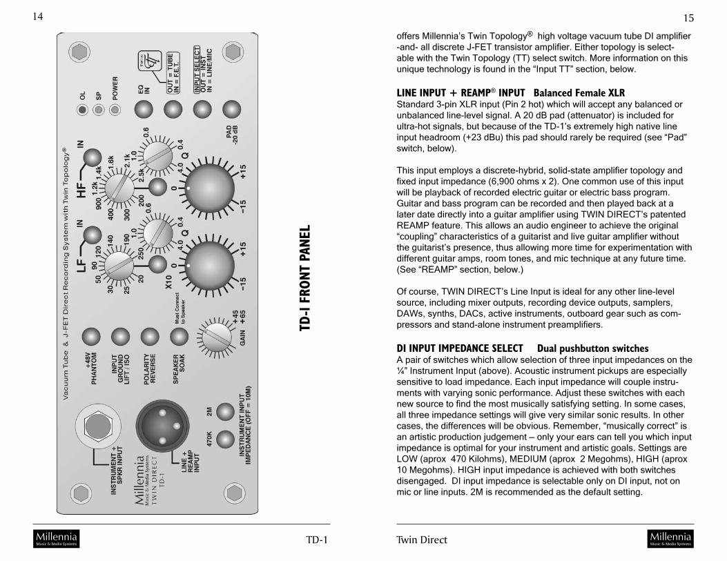
offers Millennia’s Twin Topology® high voltage vacuum tube DI amplifier -and- all discrete J-FET transistor amplifier. Either topology is select-able with the Twin Topology (TT) select switch. More information on this unique technology is found in the “Input TT” section, below.
LINE INPUT + REAMP® INPUT Balanced Female XLR Standard 3-pin XLR input (Pin 2 hot) which will accept any balanced or unbalanced line-level signal. A 20 dB pad (attenuator) is included for ultra-hot signals, but because of the TD-1’s extremely high native line input headroom (+23 dBu) this pad should rarely be required (see “Pad” switch, below).
This input employs a discrete-hybrid, solid-state amplifier topology and fixed input impedance (6,900 ohms x 2). One common use of this input will be playback of recorded electric guitar or electric bass program. Guitar and bass program can be recorded and then played back at a later date directly into a guitar amplifier using TWIN DIRECT’s patented REAMP feature. This allows an audio engineer to achieve the original “coupling” characteristics of a guitarist and live guitar amplifier without the guitarist’s presence, thus allowing more time for experimentation with different guitar amps, room tones, and mic technique at any future time. (See “REAMP” section, below.)
Of course, TWIN DIRECT’s Line Input is ideal for any other line-level source, including mixer outputs, recording device outputs, samplers, DAWs, synths, DACs, active instruments, outboard gear such as com-pressors and stand-alone instrument preamplifiers.
DI INPUT IMPEDANCE SELECT Dual pushbutton switchesA pair of switches which allow selection of three input impedances on the ¼” Instrument Input (above). Acoustic instrument pickups are especially sensitive to load impedance. Each input impedance will couple instru-ments with varying sonic performance. Adjust these switches with each new source to find the most musically satisfying setting. In some cases, all three impedance settings will give very similar sonic results. In other cases, the differences will be obvious. Remember, “musically correct” is an artistic production judgement — only your ears can tell you which input impedance is optimal for your instrument and artistic goals. Settings are LOW (aprox 470 Kilohms), MEDIUM (aprox 2 Megohms), HIGH (aprox 10 Megohms). HIGH input impedance is achieved with both switches disengaged. DI input impedance is selectable only on DI input, not on mic or line inputs. 2M is recommended as the default setting.
TD-1
FRON
T PA
NEL

TD-� MillenniaMusic & Media Systems Twin Direct
��
MillenniaMusic & Media Systems
1�
a speaker cabinet. Note that the power amplifier must be plugged into speakers designed for the full power rating of the amplifier whenever the power amplifier is feeding the TWIN DIRECT. A typical application would be taking a parallel feed from a guitar amplifier or speaker cabinet during live or studio performance. Power amplifier output should be wired in “parallel” with speakers and the TWIN DIRECT’s Instrument Input jack. TWIN DIRECT will not effect the sound or performance of the power am-plifier or speakers. TWIN DIRECT will accept power amplifier input when this switch is depressed and illuminated. Insert a power amplifier into the TWIN DIRECT only when this switch is depressed and illuminated. Failure to do so could result in serious damage.
Wonderfully rich and spacious electric guitar recordings can be achieved by using a pair of microphones on a guitar speaker cabinet, along with a direct feed into TD-1’s Speaker Soak input — with all three signals mixed together. Try using a pair of sonically dissimilar microphones, such as a Royer 121 and Josephson 606 (two of our favorites). Place each mic in a different position to maximize its unique strengths. One trick to maximize tonal “fullness” is to focus your ears on the “hum” and “hiss” of an idle guitar amp speaker, then position mics to maximize the depth and pres-ence of that hum and hiss.
GAIN CONTROLA potentiometer offering up to 65 dB of gain for the mic input and 45 dB for instrument and line .
— FRONT PANEL: EQUALIZER SECTION —
PARAMETRIC EQ BAND IN/OUT Pushbutton Switch “IN”A switch (2 ea) which places its associated Eq band in circuit or out of circuit. There are two bands of fully parametric equalization on the TD-1. Frequency bands are labeled LF [20 Hz - 2.5 kHz] and HF [250 Hz - 25 kHz]. An Eq band is in circuit when its associated band switch and main Eq on/off switch (below) are depressed and LEDs are illuminated. Be-cause of the equalizer’s unique network-shunt design, Eq bands should have no detectable sonic signature when they are in circuit as long as the boost/cut control is set at zero. Band In/Out switches are provided both for comparing a single Eq band setting versus flat-band response, and for bypassing the Eq band entirely.
PARAMETRIC EQ BOOST/CUT CONTROLConductive plastic rotary potentiometer (2 ea) offering up to 15 dB of
+48V PHANTOM POWER Pushbutton Switch A switch which provides phantom power (+48 Volts DC) to the micro-phone. When this switch is depressed (illuminated red), phantom power is applied simultaneously through dual 6.81k ohm resistors to pins 2 and 3 of the rear panel three pin female XLR mic input connector. Use phantom power with condenser and other microphones requiring tradi-tional phantom supply. Do not use phantom with ribbons, moving coil, and other microphones which do not require phantom power. Use care, as well, not to insert or extract mic cables from the TD-1 when phantom power is active. This could damage both microphone and the sensitive HV-3 front end.
INPUT GROUND LIFT / ISOLATE Pushbutton SwitchA switch which removes the ¼” Instrument (DI) Input ground from TWIN DIRECT’s internal audio grounding. This switch also employs an internal jumper which selects true ground lift, or ground “isolation” via resistive and capacitive coupling (See Jumper Map). When jumper is installed and this switch is depressed, ground is isolated via series resistance. When jumper is not installed (factory default), and switch is depressed, ground is lifted. A momentary pop may occur when lifting grounds – you may wish to remove power from the TWIN DIRECT when experimenting with any ground lifting technique.
Note that Input Ground Lift / Isolate should only be used in cases where a ground loop cannot be corrected by first lifting earth or output grounds. Lifting earth ground from power ground will usually correct ground loops and hum problems. Of course, for safety, never defeat the earth/chassis power cord ground bond. Always assure that the “third pin” (earth ground) on the IEC power cord remains connected to the TWIN DIRECT’s IEC input connector. If you must lift earth ground, you may do this via the rear panel switch. (See “Earth Ground / Isolate Lift” switch and “Output Ground Lift” switch, below.)
POLARITY REVERSE Pushbutton SwitchA switch which reverses polarity of the TD-1 signal path immediately after the gain adjustment amplifier. See Signal Flow Diagram for detail. Polar-ity on main outputs is flipped 180 degrees with respect to the input when this switch is depressed and illuminated.
SPEAKER SOAKtm INPUT Pushbutton SwitchA switch which allows the Instrument DI / Speaker Soak Input (above) to accept signal directly from the output of a power amplifier connected to

TD-� MillenniaMusic & Media Systems Twin Direct
��
MillenniaMusic & Media Systems
1�
— FRONT PANEL: ROUTING SECTION —
LED INDICATORS Power / SP / OLThree LEDs (Light Emitting Diodes) which indicate the presence of DC power (Amber), the presence of a nominal (-25 dBu) audio signal (Green), and the presence of an audio signal which has exceeded +26 dBu at the balanced line level output (Red). Note that TWIN DIRECT’s balanced line level output has a maximum output level of +32 dBu. As such, when the red overload LED turns on, the TD-1 balanced line out-put is not clipping, but has twice the reserve output voltage headroom remaining before clipping. The OL LED is set to indicate a maximum operating level in typical audio environments.
INPUT “TT” TWIN TOPOLOGY Pushbutton SwitchA switch which selects the amplifier topology used to buffer the DI Instru-ment Input. When switch is depressed and illuminated, the Instrument Input is routed to an all-discrete, solid-state J-FET (field-effect transistor) DI buffer amplifier providing musically accurate Millennia audio perfor-mance. When switch is not depressed and not illuminated, the Instrument Input is routed to a high voltage twin triode vacuum tube (12AT7) DI buffer amplifier which can provide a softer, rounder tonal coloration. Note that Twin Topology input amplifiers are available only on the DI input, not on the Mic or Line inputs. Mic and Line inputs are routed directly to a discrete-hybrid solid-state amplifier (see Signal Flow Diagram).
INPUT SELECT Pushbutton SwitchA switch which selects between the Line/Mic and Instrument inputs. When switch is depressed and illuminated, the Line/Mic Input is selected. When switch is not depressed and non-illuminated, the Instrument DI Input is selected.
PAD -20 dB Pushbutton SwitchA switch which attenuates (“pads”) all inputs (balanced or unbalanced) by -20 dB, thus increasing the maximum input headroom. Pad is engaged when switch is depressed and illuminated. In most recording or stage ap-plications, this pad will not be necessary and is included only for unusu-ally hot sources.
boost and cut. Frequency curve shape is peak/dip type (see “Q”). The Boost / Cut potentiometer has 21 detent positions for accurate repeat-ability and session logging. Detents can be removed by the factory upon customer request.
PARAMETRIC EQ FREQUENCY CONTROLConductive plastic rotary potentiometer (2 ea) which sweeps all center frequencies from 20 Hz to 25 kHz. The low band (LF) sweeps 20 Hz to 250 Hz -or- 200 Hz to 2.5 kHz, depending on the status of Frequency Range Switch (below). The high band (HF) sweeps 250 Hz to 2.5 kHz -or- 2.5 kHz to 25 kHz, depending on the status of Frequency Range Switch (below). This control is optionally available with 21-step detents for accurate repeatability and logging.
PARAMETRIC EQ FREQ RANGE SELECT Pushbutton Switch “10X”A switch (2 ea) which selects 1X or 10X parametric frequency multiplier. When switch is depressed and corresponding LED is illuminated, fre-quencies as shown on front panel legend are multiplied by 10X. When switch is not depressed and LED is not illuminated, frequencies are as shown on front panel legend.
PARAMETRIC EQ QUALITY CONTROL “Q”Conductive plastic rotary potentiometer (2 ea) which sweeps “Q” (Quality factor) from 0.4 to 4.0. “Q” is defined as the ratio of the center frequency to the bandwidth. For example, a filter boost setting with “3 dB down” points near 100 Hz and 1000 Hz exhibits a “Q” of approximately 0.4. To achieve a reasonably equivalent response of shelving Eq, simply dial in the broadest Q (0.4) and boost or cut near a typical frequency extreme (e.g., 50 Hz or 10 kHz). This control is optionally available with 21-step detents for accurate repeatability and session logging.
PARAMETRIC EQ IN/OUT SELECT Pushbutton Switch “EQ IN”A switch which places the single (yes, only one) active Eq amplifier in the signal path. Minimal signal path Eq topology assures consistently faithful musical performance.

TD-� MillenniaMusic & Media Systems Twin Direct
2�
MillenniaMusic & Media Systems
�0
TD-1
REAR
PAN
EL
REAR PANEL
MICROPHONE INPUT “HV-3 MIC IN” Millennia’s HV-3 microphone preamplifier is a world standard in classical and critical acoustic music recording. Used to record well over half of all major Hollywood film scores, chosen by countless recording and touring artists, employed by numerous microphone manufacturers for research and development, and found in more symphony and opera halls than any other — we believe there is no better choice when musical reality and dynamic uniformity are sonic priorities.
HV-3 input is a conventional 3-pin female XLR input jack for use with all standard balanced microphones, both phantom and non-phantom pow-ered. Provides +48 Volts DC Phantom powering via front panel switch. Input impedance is approximately 6,200 ohms with phantom power switched in.
Microphone Input shares the same internal signal path as the balanced line level (front panel) input but is not designed as a mixing path. For opti-mal performance when line input is in use, disconnect microphone, and visa versa. To achieve a signal path that is identical to Millennia’s HV-3B, HV-3C, or HV-3D units, use the active balanced line output (Main Output #1, below).
Pin 2 is positive polarity. Pin 3 is negative polarity. Connector contacts are Neutrik gold plated. It is suggested that XLR cable connectors used with the TD-1 employ identical plating. Maximum microphone input level is +23 dBu. For reference, a Neumann U87Ai directly in front of a screaming vocalist (127 dB SPL) will output approximately -6 dBu.
TRANSFORMER-COUPLED (GALVANIC ISOLATION) BALANCED OUTPUTUnsatisfied with “off-the-shelf” DI transformer solutions, Millennia de-signed a superior DI-dedicated transformer from the ground up. This superior large geometry transformer (Millennia type DIT-01) exhibits better than 3 Hz to 300 kHz frequency response (-3 dB), very low distor-tion, and excellent phase uniformity.
Output employs conventional 3-pin male XLR connector providing the transformer-coupled, fully “galvanically isolated” microphone level signal. Pin 1 is ground. Pin 2 is positive polarity. Pin 3 is negative polarity. Out-put impedance is approximately 150 ohms, which is nominally equivalent to most professional recording microphone. Ground (pin 1) may be lifted by engaging (up position) the toggle switch to the right of this XLR (see rear panel drawing).
TD-� MillenniaMusic & Media Systems Twin Direct
2�
MillenniaMusic & Media Systems
��
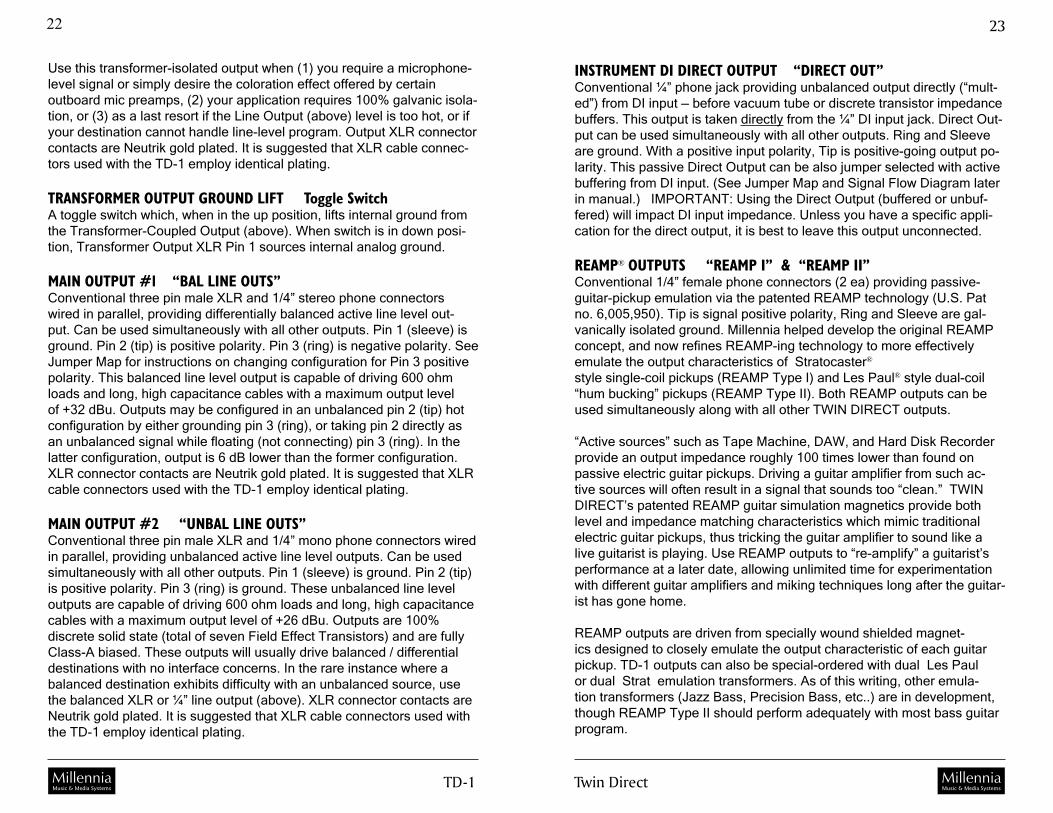
INSTRUMENT DI DIRECT OUTPUT “DIRECT OUT”Conventional ¼” phone jack providing unbalanced output directly (“mult-ed”) from DI input — before vacuum tube or discrete transistor impedance buffers. This output is taken directly from the ¼” DI input jack. Direct Out-put can be used simultaneously with all other outputs. Ring and Sleeve are ground. With a positive input polarity, Tip is positive-going output po-larity. This passive Direct Output can be also jumper selected with active buffering from DI input. (See Jumper Map and Signal Flow Diagram later in manual.) IMPORTANT: Using the Direct Output (buffered or unbuf-fered) will impact DI input impedance. Unless you have a specific appli-cation for the direct output, it is best to leave this output unconnected.
REAMP® OUTPUTS “REAMP I” & “REAMP II”Conventional 1/4” female phone connectors (2 ea) providing passive- guitar-pickup emulation via the patented REAMP technology (U.S. Pat no. 6,005,950). Tip is signal positive polarity, Ring and Sleeve are gal-vanically isolated ground. Millennia helped develop the original REAMP concept, and now refines REAMP-ing technology to more effectively emulate the output characteristics of Stratocaster®
style single-coil pickups (REAMP Type I) and Les Paul® style dual-coil “hum bucking” pickups (REAMP Type II). Both REAMP outputs can be used simultaneously along with all other TWIN DIRECT outputs.
“Active sources” such as Tape Machine, DAW, and Hard Disk Recorder provide an output impedance roughly 100 times lower than found on passive electric guitar pickups. Driving a guitar amplifier from such ac-tive sources will often result in a signal that sounds too “clean.” TWIN DIRECT’s patented REAMP guitar simulation magnetics provide both level and impedance matching characteristics which mimic traditional electric guitar pickups, thus tricking the guitar amplifier to sound like a live guitarist is playing. Use REAMP outputs to “re-amplify” a guitarist’s performance at a later date, allowing unlimited time for experimentation with different guitar amplifiers and miking techniques long after the guitar-ist has gone home.
REAMP outputs are driven from specially wound shielded magnet-ics designed to closely emulate the output characteristic of each guitar pickup. TD-1 outputs can also be special-ordered with dual Les Paul or dual Strat emulation transformers. As of this writing, other emula-tion transformers (Jazz Bass, Precision Bass, etc..) are in development, though REAMP Type II should perform adequately with most bass guitar program.
Use this transformer-isolated output when (1) you require a microphone-level signal or simply desire the coloration effect offered by certain outboard mic preamps, (2) your application requires 100% galvanic isola-tion, or (3) as a last resort if the Line Output (above) level is too hot, or if your destination cannot handle line-level program. Output XLR connector contacts are Neutrik gold plated. It is suggested that XLR cable connec-tors used with the TD-1 employ identical plating.
TRANSFORMER OUTPUT GROUND LIFT Toggle Switch A toggle switch which, when in the up position, lifts internal ground from the Transformer-Coupled Output (above). When switch is in down posi-tion, Transformer Output XLR Pin 1 sources internal analog ground.
MAIN OUTPUT #1 “BAL LINE OUTS”Conventional three pin male XLR and 1/4” stereo phone connectors wired in parallel, providing differentially balanced active line level out-put. Can be used simultaneously with all other outputs. Pin 1 (sleeve) is ground. Pin 2 (tip) is positive polarity. Pin 3 (ring) is negative polarity. See Jumper Map for instructions on changing configuration for Pin 3 positive polarity. This balanced line level output is capable of driving 600 ohm loads and long, high capacitance cables with a maximum output level of +32 dBu. Outputs may be configured in an unbalanced pin 2 (tip) hot configuration by either grounding pin 3 (ring), or taking pin 2 directly as an unbalanced signal while floating (not connecting) pin 3 (ring). In the latter configuration, output is 6 dB lower than the former configuration. XLR connector contacts are Neutrik gold plated. It is suggested that XLR cable connectors used with the TD-1 employ identical plating.
MAIN OUTPUT #2 “UNBAL LINE OUTS”Conventional three pin male XLR and 1/4” mono phone connectors wired in parallel, providing unbalanced active line level outputs. Can be used simultaneously with all other outputs. Pin 1 (sleeve) is ground. Pin 2 (tip) is positive polarity. Pin 3 (ring) is ground. These unbalanced line level outputs are capable of driving 600 ohm loads and long, high capacitance cables with a maximum output level of +26 dBu. Outputs are 100% discrete solid state (total of seven Field Effect Transistors) and are fully Class-A biased. These outputs will usually drive balanced / differential destinations with no interface concerns. In the rare instance where a balanced destination exhibits difficulty with an unbalanced source, use the balanced XLR or ¼” line output (above). XLR connector contacts are Neutrik gold plated. It is suggested that XLR cable connectors used with the TD-1 employ identical plating.
TD-� MillenniaMusic & Media Systems Twin Direct
2�
MillenniaMusic & Media Systems
��
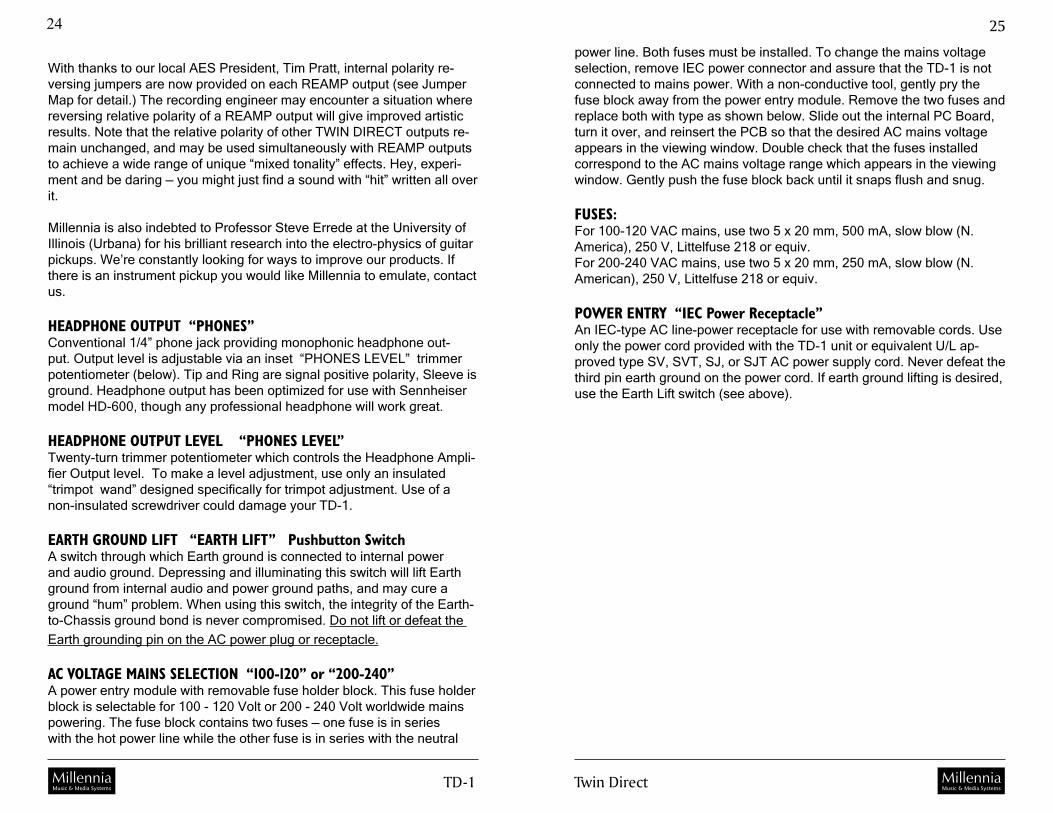
power line. Both fuses must be installed. To change the mains voltage selection, remove IEC power connector and assure that the TD-1 is not connected to mains power. With a non-conductive tool, gently pry the fuse block away from the power entry module. Remove the two fuses and replace both with type as shown below. Slide out the internal PC Board, turn it over, and reinsert the PCB so that the desired AC mains voltage appears in the viewing window. Double check that the fuses installed correspond to the AC mains voltage range which appears in the viewing window. Gently push the fuse block back until it snaps flush and snug.
FUSES:For 100-120 VAC mains, use two 5 x 20 mm, 500 mA, slow blow (N. America), 250 V, Littelfuse 218 or equiv.For 200-240 VAC mains, use two 5 x 20 mm, 250 mA, slow blow (N. American), 250 V, Littelfuse 218 or equiv.
POWER ENTRY “IEC Power Receptacle”An IEC-type AC line-power receptacle for use with removable cords. Use only the power cord provided with the TD-1 unit or equivalent U/L ap-proved type SV, SVT, SJ, or SJT AC power supply cord. Never defeat the third pin earth ground on the power cord. If earth ground lifting is desired, use the Earth Lift switch (see above).
With thanks to our local AES President, Tim Pratt, internal polarity re-versing jumpers are now provided on each REAMP output (see Jumper Map for detail.) The recording engineer may encounter a situation where reversing relative polarity of a REAMP output will give improved artistic results. Note that the relative polarity of other TWIN DIRECT outputs re-main unchanged, and may be used simultaneously with REAMP outputs to achieve a wide range of unique “mixed tonality” effects. Hey, experi-ment and be daring — you might just find a sound with “hit” written all over it.
Millennia is also indebted to Professor Steve Errede at the University of Illinois (Urbana) for his brilliant research into the electro-physics of guitar pickups. We’re constantly looking for ways to improve our products. If there is an instrument pickup you would like Millennia to emulate, contact us.
HEADPHONE OUTPUT “PHONES”Conventional 1/4” phone jack providing monophonic headphone out-put. Output level is adjustable via an inset “PHONES LEVEL” trimmer potentiometer (below). Tip and Ring are signal positive polarity, Sleeve is ground. Headphone output has been optimized for use with Sennheiser model HD-600, though any professional headphone will work great.
HEADPHONE OUTPUT LEVEL “PHONES LEVEL” Twenty-turn trimmer potentiometer which controls the Headphone Ampli-fier Output level. To make a level adjustment, use only an insulated “trimpot wand” designed specifically for trimpot adjustment. Use of a non-insulated screwdriver could damage your TD-1.
EARTH GROUND LIFT “EARTH LIFT” Pushbutton SwitchA switch through which Earth ground is connected to internal power and audio ground. Depressing and illuminating this switch will lift Earth ground from internal audio and power ground paths, and may cure a ground “hum” problem. When using this switch, the integrity of the Earth-to-Chassis ground bond is never compromised. Do not lift or defeat the
Earth grounding pin on the AC power plug or receptacle.
AC VOLTAGE MAINS SELECTION “100-120” or “200-240”A power entry module with removable fuse holder block. This fuse holder block is selectable for 100 - 120 Volt or 200 - 240 Volt worldwide mains powering. The fuse block contains two fuses — one fuse is in series with the hot power line while the other fuse is in series with the neutral

TD-� MillenniaMusic & Media Systems Twin Direct
2�
MillenniaMusic & Media Systems
��
250V
50V
50V
50V
50V
50V
50V
TRIODEVACUUM TUBEAMPLIFIER
LINEIN
MICIN
(option)
DI / INSTRUMENT IN
DIRECTOUTPUT
HEADPHONEOUTPUT
REAMPLES PAUL
OUTPUT
®
®
REAMPSTRAT
OUTPUT
®
®
BALANCEDLINE OUT
UNBALANCEDLINE OUT
TRANSFORMER-ISOLATED BALANCED
OUTPUT
ATTENUATORREAR PANEL
FEMALE XLR(front panel)
FEMALE XLR(rear panel)
1/4“ PHONEJACK (front panel)
1/4” PHONEJACK (rear panel)
1/4” PHONEJACK (rear panel)
1/4” PHONEJACK (rear panel)
1/4” PHONEJACK (rear panel)
1/4” PHONEJACK (rear panel)
1/4” PHONEJACK (rear panel)
MALE XLR(rear panel)
MALE XLR(rear panel)
MALE XLR(rear panel)
2
2
2
2
SOAK INPUTMUST BE USED WITH
SPEAKER CONNECTED!
BUFFERED
BUFFEREDUNBUFFERED
UNBUFFERED
TT SELECT
INSTRUMENTINPUT LOADING
470K
2.0M
10M
MET-01 REAMP GUITARSIMULATION MAGNETICS
®
MILLENNIA TYPE DIT-01D.I. TRANSFORMER
MET-02 REAMP GUITARSIMULATION MAGNETICS
®
ALL DISCRETESOLID STATE (FET)D.I. AMPLIFIER
HI-ZMONOLITHICSOLID STATE
AMPLIFIER
MONOLITHICSOLID STATE
AMPLIFIER
MONOLITHICSOLID STATE
AMPLIFIER
MONOLITHICSOLID STATE
AMPLIFIER
MONOLITHICSOLID STATE
AMPLIFIER(x2)
SPEAKERSOAKtm
+48V Phantom
2
PHANTOM
TT SELECT
+26 dBu Max
+32 dBu Max
50V
+35 dB DISCRETEBIPOLAR
AMPLIFIER
POLARITYREVERSE(PASSIVE)
DUAL-BAND FULLY PARAMETRICEQUALIZER 20 Hz - 25 kHz
Q = 0.4 to 4.0 +/-15 dB RANGE
OVERLOAD
SIGNAL PRESENT
DC POWER
INTERNAL DC POWER
-20 dB PAD
SP
OL
DC
MIC-LINE / INSTSELECT
EQ SELECT EQ SELECT
SINGLE-ENDED AUDIO PATH
DIFFERENTIAL AUDIO PATH
-20 dB AUTO-BALANCED ATTENUATOR
Millennia Media TD-1 “TWIN DIRECT”
Signal Path Simplified for ClaritySIGNAL FLOW DIAGRAM
Millennia Media, Inc.Http://www.mil-media.com
Copyright 2003 Millennia Media, Inc.Trademarks herein are property of
their respective holders.
+5V +25V+12V -25V+18V +50V-18V +250V
EARTH /CHASSISGROUND
POWERGROUND AUDIO
GROUNDAUDIO
GROUND
J J
INPUT SECTIONGROUND
MIC-LEVELOUTPUT GROUND
INPUT GROUND LIFT / ISOLATE OUTPUT GROUND LIFTPOWER SUPPLY GROUND LIFT / ISOLATE
ALL DISCRETECLASS-A BIAS
SOLID STATE (FET)AMPLIFIER
ISOLATE ISOLATE
POWER SUPPLY INPUT SECTION OUTPUT TRANSFORMER
LIFT LIFT LIFT
FRONTPANELGAINADJ
OPTIONALHV-3 PREAMP
SIGNAL FLOW DIAGRAM

TD-� MillenniaMusic & Media Systems Twin Direct
2�
MillenniaMusic & Media Systems
��
JUMPER MAPS
INPUT PCB
For more on jumper options inside the TWIN DIRECT, please refer to the Signal Flow Diagram and detail instruction pages. Remember, before you remove TWIN DIRECT’s top cover, always assure that the IEC AC power plug has been disconnected for at least five minutes. This will al-low potentially lethal voltages inside the TWIN DIRECT to dissipate to a safe level.
BUFFERED
BUFFERED
UNBUFF
UNBUFF
JP3
JP3
JP1
JP1
JUMPER WHICH SELECTS INTERNALPATH OF DIRECT OUTPUT.
JUMPERS AT TOP OF JP2 & JP3 GIVESACTIVE BUFFERED DIRECT OUTPUT,BUT MAY REDUCE DI INPUT IMPEDANCE.
JUMPERS AT BOTTOM OF JP2 & JP3GIVES HARD WIRED FEED FROM DIINPUT TO DIRECT OUTPUT. DEFAULT.
JUMPER WHICH SELECTS INTERNALINPUT GROUND LIFTING PATH
JUMPER ON HEADER JP1
JUMPER OFF HEADER JP1 GIVES
CREATESRESISTIVE + CAPACITIVE ISOLATIONWHEN INPUT GROUND LIFT SWITCH ISSELECTED
TRUEGROUND LIFT WHEN INPUT GROUNDLIFT SWITCH IS SELECTED. DEFAULT.
Direct Output Buffered / Non-Buffered Output JumperInput Ground Lift / Isolate Jumper — Input Board
GROUND LIFTS & ISOLATES
Grounding remains a subject of debate within the audio community, yet standard grounding practices, such as outlined by Muncy, Atkinson, Gid-dings, Windt, Fause, (et al) in their foundational AES Journal papers (J. Audio Eng. Soc. Vol 43 No. 6 1995 June), define clearly the safest and best performing grounding practices for both recording engineers and product designers. Design inconsistencies among audio product manu-facturers, along with the variables of real-world recording environments (such as AC power irregularities in large auditoriums and old churches) can present the recording engineer with “ground” far from zero volts po-tential, or even multiple “AC power grounds” exhibiting varying potential throughout a building or stage.
Because of these wide variations, a well-designed DI box must effectively anticipate all manner of audio and electrical systems. To remedy most interface problems, TWIN DIRECT provides five different methods of ground alteration options, allowing an unusually high level of user control over hums and potential mismatch.
A WORD ON ISOLATION Inside TWIN DIRECT are jumpers which allow Input and Earth Ground Lift switches to be converted to Ground Isolation paths. Ground Lift is a complete removal of all internal ground paths (earth, power, or audio) from the targeted audio connector(s). Ground Isolation is a technique whereby the ground path of targeted connector(s) is delivered in se-ries with certain passive components. Ground remains “sensed” at the connector(s), yet it becomes “isolated” via series resistance. If pure ground lifting does not cure a hum problem, isolation may be an effective technique.
Ground lift and isolation options are presented in the Rear Panel, Front Panel, and Jumper Map sections of this manual. When encountering hums or buzzes, try altering TWIN DIRECT’s internal grounding, as fol-lows: (1) Earth Ground Lift, (2) Input Ground Lift, (3) Using Transformer Output, (4) Using Transformer Output with Ground Lift, (5) Input Ground Isolate. By itself, the galvanically isolated DIT-01 transformer output will provide an ideal source of ground isolation. For your personal safety and the safety of others, never under any circumstance lift earth ground be-fore it enters the TWIN DIRECT’s IEC power connector. When IEC earth ground is secured, earth-to-chassis safety integrity is preserved under all circumstances, regardless of TWIN DIRECT’s internal ground lift or ground isolation selections.
TD-� MillenniaMusic & Media Systems Twin Direct
��
MillenniaMusic & Media Systems
30
JUMPER MAPS
MAIN PCB
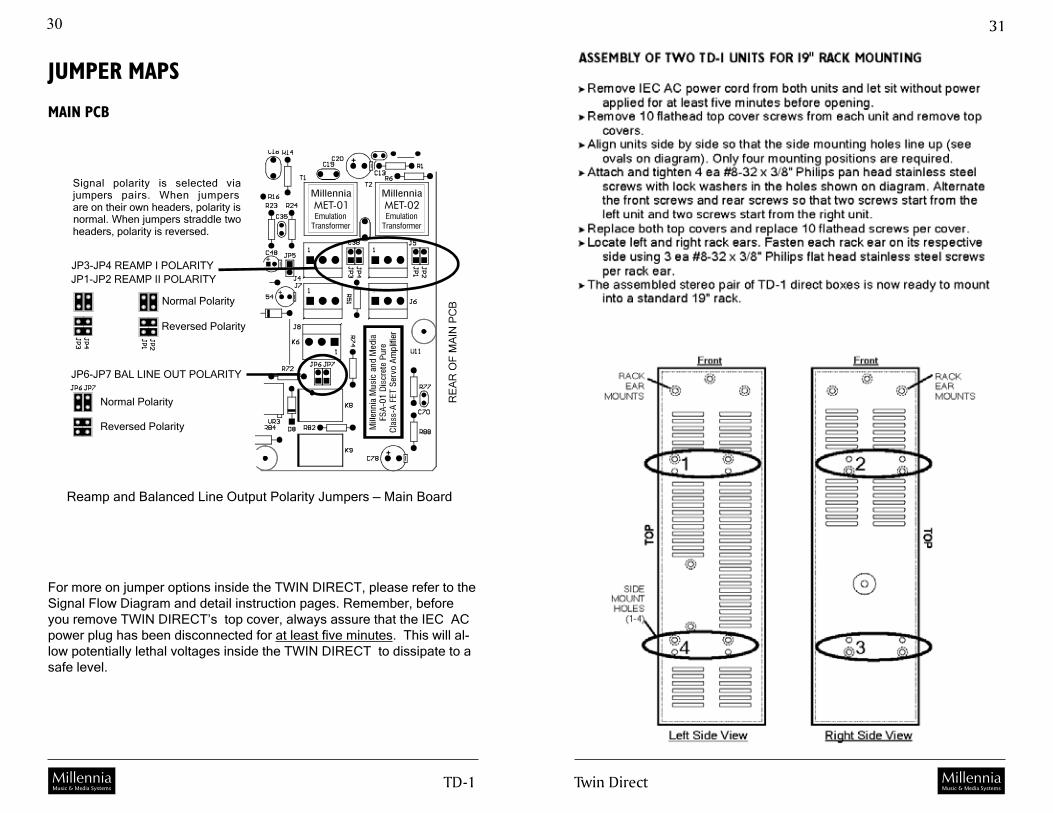
For more on jumper options inside the TWIN DIRECT, please refer to the Signal Flow Diagram and detail instruction pages. Remember, before you remove TWIN DIRECT’s top cover, always assure that the IEC AC power plug has been disconnected for at least five minutes. This will al-low potentially lethal voltages inside the TWIN DIRECT to dissipate to a safe level.
MillenniaMET-01Emulation
Transformer
MillenniaMET-02Emulation
Transformer
JP3-JP4 REAMP I POLARITYJP1-JP2 REAMP II POLARITY
JP6-JP7 BAL LINE OUT POLARITY
Signal polarity is selected viajumpers pairs. When jumpersare on their own headers, polarity isnormal. When jumpers straddle twoheaders, polarity is reversed.
Normal Polarity
Normal Polarity
Reversed Polarity
Reversed Polarity
Reamp and Balanced Line Output Polarity Jumpers — Main Board
TD-� MillenniaMusic & Media Systems Twin Direct
��
MillenniaMusic & Media Systems
3�
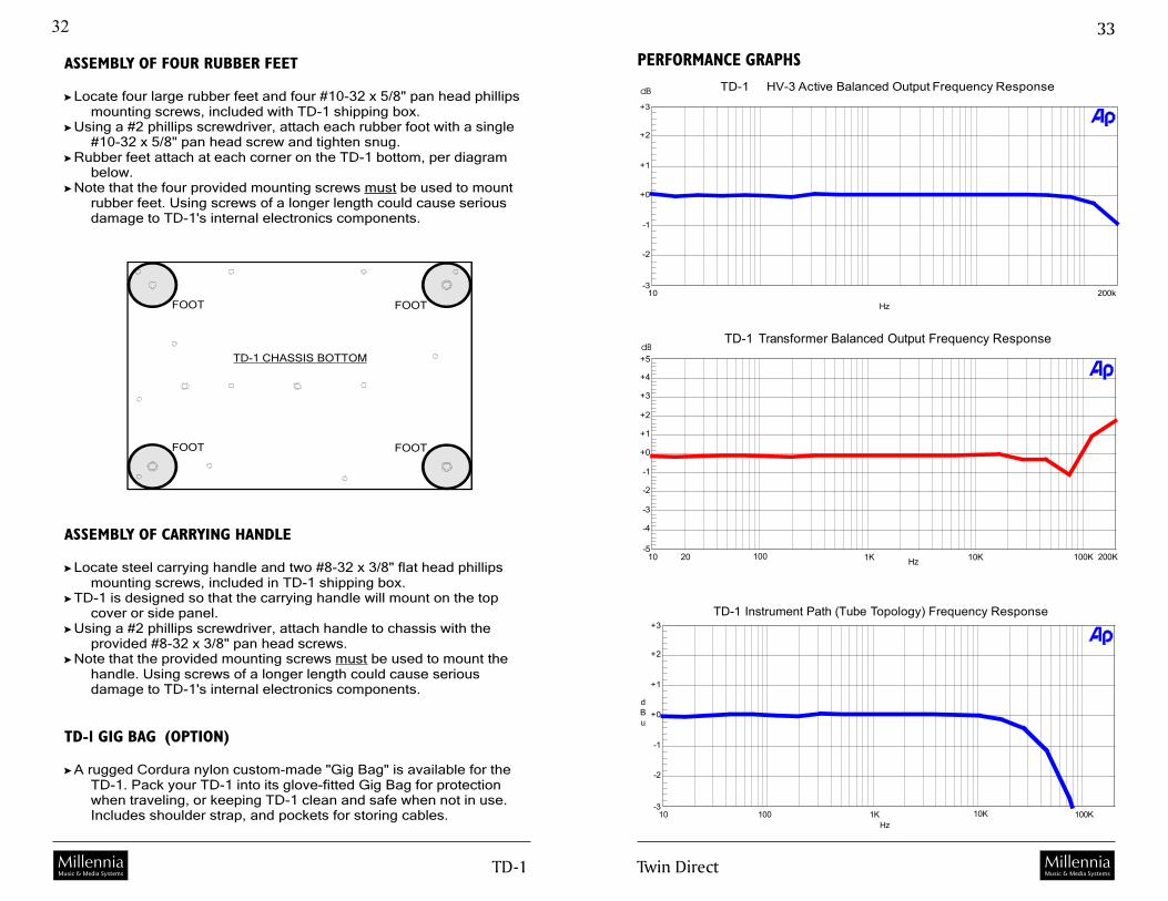
TD-1 Transformer Balanced Output Frequency Response
-5
+5
-4
-3
-2
-1
+0
+1
+2
+3
+4
10 20 200K100 1K 10K 100KHz
dB
PERFORMANCE GRAPHS
TD-1 Instrument Path (Tube Topology) Frequency Response
-3
+3
-2
-1
+0
+1
+2
dBu
10 100 1K 10K 100KHz
TD-1 HV-3 Active Balanced Output Frequency Response
-3
+3
-2
-1
+0
+1
+2
10 200kHz
dB
ASSEMBLY OF FOUR RUBBER FEET
Locate four large rubber feet and four #10-32 x 5/8" pan head phillipsmounting screws, included with TD-1 shipping box.
Using a #2 phillips screwdriver, attach each rubber foot with a single#10-32 x 5/8" pan head screw and tighten snug.
Rubber feet attach at each corner on the TD-1 bottom, per diagrambelow.
Note that the four provided mounting screws be used to mountrubber feet. Using screws of a longer length could cause seriousdamage to TD-1's internal electronics components.
must
ASSEMBLY OF CARRYING HANDLE
Locate steel carrying handle and two #8-32 x 3/8" flat head phillipsmounting screws, included in TD-1 shipping box.
TD-1 is designed so that the carrying handle will mount on the topcover or side panel.
Using a #2 phillips screwdriver, attach handle to chassis with theprovided #8-32 x 3/8" pan head screws.
Note that the provided mounting screws be used to mount thehandle. Using screws of a longer length could cause seriousdamage to TD-1's internal electronics components.
must
TD-1 GIG BAG (OPTION)
A rugged Cordura nylon custom-made "Gig Bag" is available for theTD-1. Pack your TD-1 into its glove-fitted Gig Bag for protectionwhen traveling, or keeping TD-1 clean and safe when not in use.Includes shoulder strap, and pockets for storing cables.
FOOT
TD-1 CHASSIS BOTTOM
FOOT
FOOT
FOOT

TD-� MillenniaMusic & Media Systems Twin Direct
��
MillenniaMusic & Media Systems
3�
TD-1 Line / Mic THD (Active Balanced +27 dBu output)
0.0004
0.009
0.0005
0.0007
0.001
0.002
0.003
0.0040.005
0.007
%
20 100 1K 10K 20KHz
TD-1 represents the work of many dedicated individuals. Millennia takes this opportunity to recognize the team that made it happen: Daniel & Cyn-thia La Grou, Mike Johnson, Larry Boyle, Peggy Smith, Joshua & Jason
Galbraith, Darrell Ziebell, Debby Billington, and Charlotte Flowers.
TD-1
TD-1 Instrument Path (Tube Topology) THD
0.0004
0.5
0.001
0.002
0.005
0.01
0.02
0.05
0.1
0.2
%
20 20kHz
TD-1 Mic Path Phase Response
-30
+30
-20
-10
+0
+10
+20
deg
20 50k50 100 200 500 1k 2k 5k 10k 20kHz
TD-1 Instrument Path (Solid State Topology) THD
0.0004
0.5
0.001
0.002
0.005
0.01
0.02
0.05
0.1
0.2
%
20 100 1K 10K 20K
Hz

TD-� MillenniaMusic & Media Systems
3�
TWIN DIRECT TD-1 SPECIFICATIONS
GENERAL
Instrument / DI Input Amplifier Topology TUBE: Selected dual triode vacuum tube (250V) SOLID STATE: All discrete J-FET amplifier (50V)THD + Noise, 20 Hz - 30 kHz (35 dB Gain) 0.0005% typical mic / line, 0.03% typical vacuum tube Intermodulation Distortion 0.0009% typical mic / line, 0.03% typical vacuum tubeFrequency Response @ -3 dB points 3 Hz to 300 kHz, typical. Varies with path & topologyFrequency Response @ -0.5 dB points 7 Hz to 100 kHz, typical. Varies with path & topologyFrequency Response, DIT-01 Transformer Better than 3 Hz to 300 kHz (+/- 3.0 dB)Frequency Response, DI - Tube Path -1.0 dB, better than 10 Hz to 40 kHzFrequency Response, DI - SS Path -1.0 dB, better than 5 Hz to 100 kHzMaximum Balanced Mic Input Level +23 dBu (Pad not engaged) Maximum Balanced Line Input Level +23 dBu (+43 dBu Pad engaged, or >100 Volts RMS) Maximum DI Input Level (Tube & SS) +18 dBu (+26 dBu Pad engaged, or >15 Volts RMS)Maximum Output Level +32 dBu active balanced outputs, +26 dBu unbal outputsMaximum System Gain 65 dB standard Input Impedance (mic) 6,200 ohms, nominal with phantom power engagedInput Impedance (line) 6,900 ohms, pad out. Input Impedance (DI - Tube & SS) switchable: 470K ohms / 2M ohms / 10M ohmsOutput Impedance 24.3 (x2) ohms balanced. 49.9 ohms unbalanced Noise (Mic) (Eq out, 60 dB gain) -128 dB EIN, 150 ohm sourceNoise (Line) (Eq in, 10 dB gain) -105 dBuNoise (DI) (Eq in, 10 dB gain) -90 dBu Common Mode Rejection Ratio, mic in > 60 dB typical, 100 mV CM (10 Hz - 100 kHz) > 80 dB typical @ 60 & 120 Hz, 100 mV CMPhase Error (Eq out) Less than +/- 5 degrees 50 Hz to 20 kHz, typicalThree-pin XLR Polarity Pin 2 = positive polarity, Pin 1 = ground¼” Phone Polarity (unbal) Sleeve = ground, Tip = positive polarity¼” Phone Polarity (balanced) Sleeve = ground, Tip = pos pol, Ring = neg pol
EQUALIZER
Maximum Boost & Cut +/- 15 dB (21 step detent)Parametric “Q” Adjustment Range Q = 0.4 to 4.0, sweepableLow Freq (LF) Parametric Sweep Freqs 20 Hz to 220 Hz -or- 200 Hz to 2.2 kHz (sw selectable)High Freq (HF) Parametric Sweep Freqs 250 Hz to 2.5 kHz -or- 2.5 kHz to 25 kHz (sw selectable)Bypass Selection on Each Eq Band? YesEq IN / OUT Switch? YesEq Topology Solid State
ELECTRO-MECHANICAL
Power Consumption 35 Watts, nominal Power Requirements 100VAC to 240VAC, 50/60Hz, selectable Fuses (2 required) 100-120VAC Mains 2 ea 500mA (5x20mm, U.S. slow-blow, 250V) 200-240VAC Mains 2 ea 250mA (5x20mm, U.S. slow-blow, 250V)Internal DC Power +250V, +48V, +25V, -25V, +18V, -18V, +12.6V, +5VDimensions approximately 8.5” W x 13” D x 3.5” HNet Weight approximately 16 pounds
* Maximum HV-3 preamplifier gain can be factory modified up to 85 dB upon customer request.Millennia Media reserves the right to change specification and delivery without notice.