tSO F T W A R E U P G R A D E P L A N · P a ra g ra p h T itle P a g e 1. SC O PE 1 1.1...
100
tSOFTWARE UPGRADE PLAN - >n FOR THE i / REDHOOK ENGINEERING SERVICES (RES) UPDATED FINAL Document Control Number 8002123 CAGE No. 66948 February 1997 Prepared by: HARRIS CORPORATION GOVERNMENT COMMUNICATION SYSTEMS DIVISION P.O. BOX 91000 MELBOURNE, FL 32902 ALL BTFORHATIOH C0HTAIHED HEREIN IS UNCLASSIFIED DATE 06-26-2007 BY 65179 DHH/TAH/KRS/cb
Transcript of tSO F T W A R E U P G R A D E P L A N · P a ra g ra p h T itle P a g e 1. SC O PE 1 1.1...

tSOFTWARE UPGRADE PLAN - >n
FOR THE i
/
REDHOOK ENGINEERING SERVICES (RES)
UPDATED FINAL
Document Control Number 8002123
CAGE No. 66948
February 1997
Prepared by:
HARRIS CORPORATION
GOVERNMENT COMMUNICATION SYSTEMS DIVISION
P.O. BOX 91000
MELBOURNE, FL 32902
ALL BTFORHATIOH C0HTAIHED HEREIN IS UNCLASSIFIED DATE 06-26-2007 BY 65179 DHH/TAH/KRS/cb

SOFTWARE UPGRADE PLAN
FOR THE
REDHOOK ENGINEERING SERVICES (RES)
Approved By:
Approved By: Approved Bv:
Approved B Approved By:
C
b 6 b 7 C

RECORD OF REVIEWS AND HISTORY
VERSION
0
A
DATE
4/96
02/97
DESCRIPTION
Final
\ Updated Final
i

TABLE OF CONTENTS
Paragraph Title Page
1. SCOPE 1
1.1 Identification 1 1.2 Document Overview 1 1.3 Relationship to Other Plans 1
2. REFERENCED DOCUMENTS 2
2.1 Government Documents 2 2.2 Non-Government Documents 2 2.3 Program Documentation 3
3. SOFTWARE UPGRADE MANAGEMENT 4
3.1 Program Organization and Resources 4 3.1.1 Contractor Facilities 4 3.1.1.1 Dedicated Project Facilities 4 3.1.2 Government Furnished Equipment 4 3.1.3 Organization Structure 5 3.1.4 Personnel 6 3.2 Program Plan and Schedule 8 3.2.1 Task Process 8 3.2.2 Schedule 8 3.3 Risk Management 8 3.3.1 Risk Determination 10 3.3.2 Analysis of Factors 11 3.3.3 Identification and Analysis of Alternatives 11 3.3.4 Selection of Alternatives/Implementation 11 3.3.5 Assign Resources 11 3.3.6 Implementation and Measurement of Effectiveness 11 3.3.7 Identification of Risk Areas 12 3.4 Security 13 3.5 Requirements Verification 13 3.6 Formal Reviews 13 3.6.1 Senior Management Reviews 13 3.6.2 Program Startup Review , 13 3.6.3 Sponsor Monthly Meetings 13 3.7 Software Control 13 3.7.1 Software Development Library 13 3.7.2 Software Development Folders (SDF) 15 3.8 Corrective Action Process 16
4. SOFTWARE ENGINEERING 1 18
4.1 Organization and Resources - Software Engineering 18 4.1.1 Organizational Structure/Personnel - Software Engineering 18 4.1.2 Software Engineering Environment 18 4.1.2.1 Software Items 18
ii

TABLE OF CONTENTS (Continued)
Paragraph Title Page
4.1.2.2 Hardware and Firmware Items 19 4.1.2.3 Proprietary Nature and Sponsor Rights : 19 4.2 Software Standards and Procedures 20 4.2.1 Software Upgrade Techniques and Methodologies 20 4.2.1.1 Preliminary / Detailed Design 20 4.2.1.2 Code and CSU Test 21 4.2.1.3 CSC Integration and Test 22 4.2.1.4 System (CSC1) Integration and Test 22 4.2.2 New Software Development Process 23 4.2.2.1 Software Requirements Analysis 24 4.2.2.1.1 Inputs 25 4.2.2.1.2 Process Steps 25 4.2.2.1.3 Products J 26 4.2.2.1.4 Reviews 26 4.2.2.1.5 Activity Completion 26 4.2.2.2 Preliminary Design 26 4.2.2.2.1 CSCI Architectural Design (Top-Levet Design) 26 4.2.2.2.1.1 Inputs 27 4.2.2.2.1.2 Process Steps 27 4.2.2.2.1.3 Products 27 4.2.2.2.1.4 Reviews 28 4.2.2.2.1.5 Activity Completion '. 28 4.2.2.3 CSCI Detailed Design 28 4.2.2.3.1 Inputs 28 4.2.2.3.2 Process Steps 28 4.2.2.3.3 Products 28 4.2.2.3.4 Reviews 29 4.2.2.3.5 Activity Completion 29 4.2.2.4 Software Implementation 29 4.2.2.4.1 Preparing for unit testing 30 4.2.2.4.2 Performing unit testing 30 4.2.2.4.3 Revision and retesting ' 31 4.2.2.4.4 Analyzing and recording unit test results 31 4.2.2.5 Unit integration and testing 31 4.2.2.5.1 Performing unit integration and testing 32 4.2.2.5.2 Revision and retesting 32 4.2.2.5.3 Analyzing and recording unit integration and test results 32 4.2.3 Software Port Process 33 4.2.3.1 Software Requirements Analysis 33 4.2.3.1.1 Inputs 33 4.2.3.1.2 Process Steps 33 4.2.3.1.3 Products : 34 4.2.3.1.4 Reviews 34 4.2.3.1.5 Activity Completion 34 4.2.3.2 Recompile Code 34 4.2.3.3 CSC Testing 34 4.2.3.4 CSCI Integration and Testing 35 4.2.4 Coding Standards 35
iii
TABLE OF CONTENTS (Continued)
Paragraph Title Page
5. ACCEPTANCE TESTING (ATP) 36
5.1 Organization and Resources 36 5.2 Test Approach/Philosophy 36
6. SOFTWARE QUALITY ASSURANCE 37
6.1 Scope 37 6.1.1 Identification 37 6.1.2 Document Overview 37 6.1.3 Relationship to Other Plans 37 6.1.4 Referenced Internal Documents 37 6.2 Organization and Resources 38 6.2.1 Organization 38 6.2.2 Personnel 38 6.3 Software Quality Program Procedures, Tools, and Records 38 6.3.1 Procedures 38 6.3.1.1 Evaluation of Documentation 38 6.3.1.2 Evaluation of Software and Configuration Management 39 6.3.1.2.1 Software Upgrades and Enhancements 39 6.3.1.2.2 Software Upgrade Audits 40 6.3.1.2.3 Software Configuration Management/Library Audits 40 6.3.1.3 Documentation and Media Distribution 40 6.3.1.4 Evaluation of Storage and Handling 40 6.3.1.5 Corrective Action System 40 6.3.1.6 Formal Reviews 41 6.3.1.7 Walkthroughs 41 6.3.1.8 Certification and Software Acceptance 41 6.3.1.9 Evaluation of Non-Deliverable Software 41 6.3.1.10 Evaluation of Software Testing 42 6.3.1.11 Control of Deliverable and Non-deliverable Tools 42 6.3.1.12 Firmware Control : 42 6.3.2 Software Quality Records 42
7. SOFTWARE CONFIGURATION MANAGEMENT PLAN (SCMP) 43
7.1 Scope , 43 7.1.1 Identification 43 7.1.2 Document Overview 43 7.1.3 Referenced Internal Documents 43 7.2 Organization and Resources 43 7.2.1 Organization 43 7.2.2 Personnel 43 7.3 Process 44 7.3.1 Software Development Library (SDL) 44 7.3.2 Software Change Report (SCR) 44 7.3.3 Software Review Board (SRB)/Configuration Control Board (CCB) 44
iv

TABLE OF CONTENTS (Continued)
Paragraph Title Page
7.4 Status Accounting 45 7.4.1 Software Configuration Status Reports 45 7.4.1.1 Open SCR Status 48 7.4.1.2 Software Status Reports 48 7.5 Storage 48
7.6 Delivery of Software 49
8. LIST OF ACRONYMS AND ABBREVIATIONS 50
APPENDK A REDHOOK CODING STANDARDS Workstation and PDU 59 APPENDIX B REDHOOK CODING STANDARDS Bridge 70
v

LIST OF ILLUSTRATIONS
Paragraph Title Page
3.1.3-1 Organizational Interfaces for Software Upgrade 3.1.3-2 Organizational Chart 3.2.1 ROM/Task Flow Activities 3.3 Software Risk Analysis Management Methodology. 3.7.1 Baseline Control 3.8 Software Change Report (SCR) Process 4.2.2-1 Standard Water-Fall Model 4.2.2.4.2-1 Unit Testing Process 4.2.2.4.2-2 Unit Testing Process 7.3.2-1 Software Change Report (Sheet 1 of 2) 7.3.2-2 Software Change Report (Sheet 2 of 2)
5 7 8 9
14 17 23 30 31 46 47
LIST OF TABLES
Table Title Page
2.3 RES Upgrade Documentation 3.1.1.1 Required Project Facilities 3.3.1 RES Software Development Metrics. 3.3.7 RES Software Risk Areas 4.1.2.1 Required Software Items 4.1.2.2 Required Hardware Items 6.3.1 Cross Reference Compliance Matrix.
3 4
10 12 18 19 39
vi

1. 1.1
SCOPE Identification
Document No. 8002123 CAGE No. 66948
This Software Upgrade Plan (SUP) establishes the plans for software development to be used during all Computer Software Configuration Item (CSCI) upgrade/enhancements for the Redhook Engineering Services (RES) program, JA 1174.
1.2 Document Overview
This plan describes the methods that the program team will use to analyze, design, implement, and test the software.
o Section 2 lists the other documents which apply to this software upgrade plan.
o Section 3 describes the software upgrade management activities which the RES program team will use for this software development.
o Section 4 lists the software engineering resources.
o Section 5 describes the acceptance test procedures that will be used for this software upgrade activity.
o Section 6 references the software product evaluation activities performed by the Harris Software Quality Assurance organization.
o Section 7 references the software configuration control and management activities performed by the Software Configuration Management organization.
This document represents the implementation of the policies documented in die Harris GCSD Software Engineering Division Operating Instruction (GCSD-408) and the GCSD Software Practices and Procedures Handbook. In die event of conflict between this SUP and the Division Operating Instruction, the Division Operating Instruction will take precedence.
This SUP is intended to be a living document that reflects the project specific software development practices and procedures as they evolve throughout the life of the program. This SUP is a controlled document and will be revised as necessary.
1.3 Relationship to Other Plans
This plan describes the resources and activities associated with the RES program. The Software Engineering, Software Test, Software Configuration Management and Software Quality Assurance functions are described herein. As such, this document is the stand alone plan for the software upgrade effort.
ALL IETF0PJIATION COHTAHJED HEREIff IS UNCLASSIFIED DATE 06-27-2007 BY 65179 DHH/TAH/KSR/cb
Redhook Engineering Services (RES) Software Upgrade Plan 1

2. 2.1
2.2
Document No. 8002123 CAGE No. 66948
REFERENCED DOCUMENTS Government Documents
None. Non-Government Documents
The following documents of the exact issue shown fonn a part of this document to the extent described herein. In the event of conflict between the documents referenced herein and the contents of this document, the contents of this document shall be considered a superseding requirement.
SPECIFICATIONS:
184469
184470
184471
STANDARDS:
S-401-003-1 3 JUL 86
S-401-006-1 10 SEP 90
CSD-411-001 12 AUG 96
Proprietary
Proprietary
Proprietary
Harris Government Systems Sector Standard Procedure for Engineering Changes, Processing
Harris Government Systems Sector Standard Procedure for Design Reviews
Harris Communications Systems Division Software Engineering Manual
DRAWINGS:
None
OTHER PUBLICATIONS:
None
Redhook Engineering Services (RES) Software Upgrade Plan 2

• • Document No. 8002123
CAGE No. 66948
2.3 Program Documentation
Table 2.3 lists the software related documentation that will be developed during this effort along with the due dates and organizational responsibilities for generation and approval.
Table 2.3. RES Upgrade Documentation
Document
Software Upgrade Plan (SUP)
Software Quality Plan (SQP)
Software Configuration Mgt Plan (SCMP)
Software Requirement Spec (SRS)
Update/New
New
New
New
Update
Writing Responsibility
SW, SCM, SQA
SQA
SCM
SW
Approval Responsibility
PM, SE, SQA, SCM, SWPE
PM, SE, SQA, SWPE
PM, SE, SQA, SWPE
SQA, SE, SWPE
Key: SW Software Engineer SCM Software Configuration Management SQA Software Quality Assurance PM Program Manager SE System Engineer
None of the above document; are required by contract.
Redhook Engineering Services (RES) Software Upgrade Plan 3

Document No. 8002123 CAGE No. 66948
3. SOFTWARE UPGRADE MANAGEMENT
The RES software upgrade effort will be managed in accordance with the policies documented in the GCSD Software Engineering Standards Division Operating Instruction (GCSD-408). The following paragraphs describe the program specific implementation of those policies that will be used to manage die software effort throughout its upgrade.
3.1 Program Organization and Resources
The following paragraphs summarize die laboratory space, equipment resources, and project organization required for the software upgrade project described herein.
3.1.1 Contractor Facilities
The Program Manager is responsible for identifying all facilities at Harris to be used on the contract. This includes any required secure areas and the location of project specific resources. The Engineering Manager and Software Project Engineer are responsible for identifying the software engineering environment requirements to Program Management.
3.1.1.1 Dedicated Project Facilities
The following facilities will be dedicated to die RES software upgrade effort:
Table 3.1.1.1. Required Project Facilities
Required Resource
Building 24, vault 2000 including offices and lab area
Video Teleconference Room, Building 24
Start Need Date
October 26,1995
October 26,1995
End Need Date
October 26, 1997
October 26,1997
All dedicated personnel will be located within die vault. Additional office space is provided for non-dedicated personnel in the vault although some will reside in offices outside die vault area.
3.1.2 Government Furnished Equipment
The following GFE equipment is required in support of die software upgrade tasks:
b2 b7E
I
Redhook Engineering Services (RES) Software Upgrade Plan 4

Document No. 8002123 CAGE No. 66948
3.1.3
r
Organization Structure
The management interfaces and the responsibilities of the primary organizations which interact with the Software Upgrade organization are shown in Figure 3.1.3-1 and summarized as follows:
a. Program Management (PM1 - Responsible for overall program management for the project. Approves all plans and monitors cost and schedule performance, authorizes expenditure of funds, and acts as intermediary between the customer and the upgrade team.
b. Project Engineer (PE) - Ultimately responsible for the technical design and implementation of each task and metrics associated.
c. Task Leader • Responsible for the direct execution of a specific task, including cost, schedule and technical performance.
d. Systems Engineer CSE) - Responsible for the specification and allocation of all system requirements. Approves all plans and monitors technical performance for all functional development teams. Analyzes the system requirements and allocates them to hardware, software, and other system components.
e. Software Configuration Management (SCM) - Writes the Software Configuration Management Plan (SCMP), and provides the formal SCM.
f. Data Management (DM) - Responsible for the final preparation of deliverable documentation.
g. Software Quality Assurance (SOA) - Responsible for reviewing all project work for compliance to standards, specifications, plans, and procedures. Writes the Software Quality Product Plan (SQPP).
PROGRAM MANAGEMENT
(PM)
MILESTONE PERFORMANCE
SYSTEM REQUIREMENTS INPUT
BUDGET AND SCHEDULE
r
SOFTWARE REQUIREMENTS
ALLOCATION
HVWSW TRADES
SYSTEMS ENGINEERING
SOFTWARE ENGINEERING
SOFTWARE CONFIGURATION MANAGEMENT
BASELINE CODE AND DOCS
i i k MONITORS, REVIEWS, APPROVES
TECHNICAL DATA
DISCREPANCY REPORTS
PROJECT ENGINEER/TASK
LEADER
SOFTWARE QUALITY
ASSURANCE
DATA MANAGEMENT
Figure 3.13-1. Organizational Interfaces for Software Upgrade
Program tracking and reporting occur along program management lines.
Redhook Engineering Services (RES) Software Upgrade Plan 5

Document No. 8002123 CAGE No. 66948
The software upgrade team is comprised of the Software/Firmware Project Engineer, Task Leader and the personnel reporting to him/her. The individual responsibilities are summarized as follows.
a. Software/Firmware Project Engineer (SWPE) - Responsible for the Software Engineering process aspects of each software related task. With the aid and support of the PM and the SE, the SWPE exercises these responsibilities or delegates them to a S/W Task Leader for each task:
o leading and coordinating the project's Software Engineering team's efforts
o completing the software upgrade project within budget and schedule constraints
o developing and maintaining the project's software upgrade plan
o explicitly assigning responsibility for software work products and activities
o negotiating commitments
o conducting regular reviews with the upgrade leaders to track progress, plans, performance, and technical issues against the SUP
o participating with other affected groups in the overall project planning throughout the project's life
o meeting with the Program Manager to report software upgrade status
o provide SEPG metrics for all tasks to SEPG group.
b. Software Task Leader - Individual responsible for execution of a specific task, reports ultimately to SE and PM for cost/schedule/technical and to SWPE for process.
o execute task within budget and schedule constraints
o conduct regular interviews with SWPE or SE to inform of status
o coordinate technical requirements with SWPE and SE
Depending upon the scope of the task, the Task Leader may or may not have a S/W background. If the task is solely hardware related, the task leader will report directly to the PM and SE for cost, schedule and technical requirements. If the task is a mixture of both hardware and software, the task leader will be responsible to verify that the S/W engineer working the task reports to the SWPE for process control.
The program organizational chart may be seen in Figure 3.1.3-2. It represents a snapshot of how hardware and software tasks structured. A current organizational chart may be viewed in the Monthly Status Reports. As new tasks are awarded, additional blocks will be added to the chart with assigned task leaders.
3.1.4 Personnel
The required dedicated engineering staffing profile required by contract is:
o Systems Engineer (1 ea.) o Software/Firmware Engineer (1 ea.) o Software Engineer (2 ea.)
Non-dedicated personnel may be utilized whenever deemed appropriate by the team.
Redhook Engineering Services (RES) Software Upgrade Plan 6

Document No. 8002123 CAGE No. 66948
Redhook Engioeering Services Organization Chart
Dedicated Resource Pool
Figure 3.1 J-2. Organizational Chart
Redhook Engineering Services (RES) Software Upgrade Plan 7

Document No. 8002123 CAGE No. 66948
3.2
3.2.1
Program Plan and Schedule
The program consists of tasks being identified by the Sponsor and awarded for execution by the RES team. This results in a continually changing schedule. The following paragraph identifies the process in how tasks are awarded/executed.
Task Process
The program starts with the Sponsor identifying a task and respective priority. A ROM and schedule is then generated for the task. Following review by the Sponsor, approval for execution is given. If the priority is urgent, execution may also begin before any ROM or schedule is even generated. Figure 3.2.1 depicts the general process of task identification through task execution.
Assign Task We ik Cod*
Generate ROM a. gat approval to submit
ROB
Negotiate Piternieaflmpacta to
currant tasks
f_7P\ Sub ml ROM
Negotiate ROM Priority and Sehaduls
Dedicated Staff
Material
Monthly Reports, Status Briefings,
Weakly Confsranca
3.2.2 Figure 3.2.1. ROM/Task Flow Activities
Schedule
3.3
The schedule is in a state of constant change as tasks are awarded. A current schedule may always be found in the latest Monthly Status Report. The Sponsor assigns the priority of each task and may adjust them at any time.
Risk Management
The software risk management methodology implemented on the RES program is a continual part of the software upgrade process. Each SWPE or Task Leader is responsible for risk management
Redhook Engineering Services (RES) Software Upgrade Plan 8

Document No. 8002123 CAGE No. 66948
of the overall task, although risk may be identified by any team member. The procedure for the software risk analysis process is depicted in Figure 3.3.
As shown in this diagram, software risk analysis and mitigation are accomplished through the iteration of a series of steps.
RISK DETERMINATION
• ANALYSIS OF
FACTORS
• IDENTIFICATION AND ANALYSIS
OF ALTERNATIVES
• SELECTION OF ALTERNATIVE
t PLAN FOR
IMPLEMENTATION
• ASSIGN
RESOURCES
• IMPLEMENTATION
* MEASURE
EFFECTIVENESS
RISK AREAS EXAMINED KEY METRICS TRACKED
A) Technical Risk 1) Requirements 2) Constraints 3) Technology 4) Development Approach
B) Schedule Risk 1) Resources 2) Need Dates 3) Technology 4) Requirements
C) Cost Risk 1) Requirements 2) Personnel 3) Reusable Software 4) Tools & Environment
D) Operational Failure Risk 1) User Perspective 2) Technical Performance 3) Performance Envelope
E) Support Failure Risk 1) Design 2) Responsibilities 3) Tools & Environment 4) Supportability
A) Computer Resources Use (Development Host and Target Host) Planned vs Actual - CPU Capacity - I/O Capacity - Memory Resources
B) Software Development Planned vs Actual - Turnover - Labor Mix
C) Requirements Definition and Stability - Changes - Traceability - Testability
D) Software Development Progress
E) Cost/Schedule Deviations F) Software Development
Tools G) Defect Density H) SLOC Stability
Figure 3.3. Software Risk Analysis Management Methodology
Red hook Engineering Services (RES) Software Upgrade Plan 9

• • Document No. 8002123
CAGE No. 66948
3.3.1 Risk Determination
Software engineering technical activities are reviewed periodically during the weekly program meetings using die software development metrics listed in Table 3.3.1 along with the cost and schedule information provided by the Harris Project Control System (PCS). This review is performed in all phases of the software development process: software requirements analysis, preliminary design, detailed design, code and Computer Software Unit (CSU) testing, Computer Software Component (CSC) integration and testing, and system testing. These reviews keep the key issues in focus and ensure that previously defined risk areas are being resolved, and at the same time identifying potential new risks.
Table 33.1. RES Software Development Metrics
Software Development
Metric
Software Size
Software Personnel
Computer Resource Utilization
Reuse
SCR
Physical Environment
ACWP
Schedule Progress and Labor Utilization
HMI Screens
Metric Description
Planned changes to estimated and actual magnitude of software development effort based on Source Lines of Code (SLOC).
Planned changes to staffing level.
Planned changes to estimated and actual utilization of target computer resources.
Planned changes to estimated and actual reuse experienced during different phases of development.
Number of Software Change Requests (SCRs) opened, closed and number of hours to complete.
Record physical software development environment characteristics.
Actual Cost Work Performed in hours
Planned and actual performance to schedule along with planned and actual labor utilization
Number of HMI screens added
Primary Collector
S/W Task Leader
S/W Task Leader
S/W Task Leader
S/W Task Leader
S/W Task Leader
S/W Task Leader
S/W Task Leader
S/W Task Leader
S/W Task Leader
Redhook Engineering Services (RES) Software Upgrade Plan 10
Document No. 8002 2 23 CAGE No. 66948
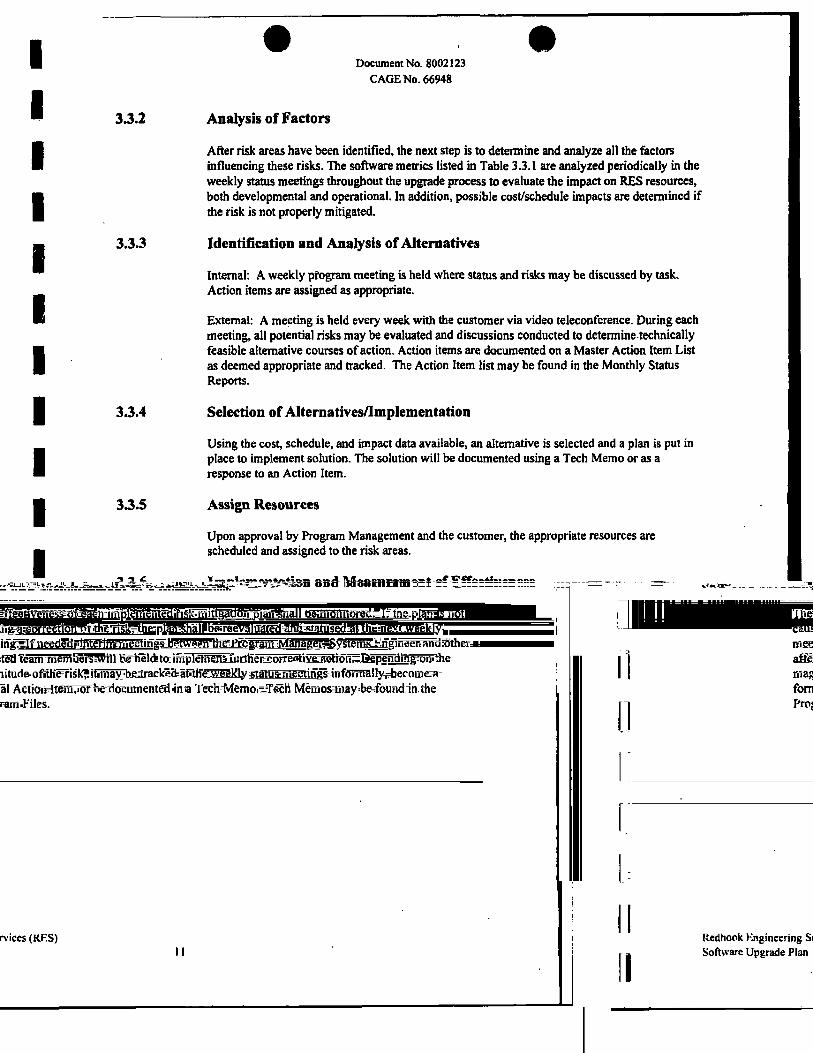
33.2 Analysis of Factors
After risk areas have been identified, the next step is to determine and analyze all the factors influencing these risks. The software metrics listed in Table 3.3.1 are analyzed periodically in the weekly status meetings throughout the upgrade process to evaluate the impact on RES resources, both developmental and operational. In addition, possible cost/schedule impacts are determined if the risk is not properly mitigated.
3.3.3 Identification and Analysts of Alternatives
Internal: A weekly program meeting is held where status and risks may be discussed by task. Action items are assigned as appropriate.
External: A meeting is held every week with the customer via video teleconference. During each meeting, all potential risks may be evaluated and discussions conducted to determine technically feasible alternative courses of action. Action items are documented on a Master Action Item List as deemed appropriate and tracked. The Action Item list may be found in the Monthly Status Reports.
3.3.4 Selection of Alternatives/Implementation
Using the cost, schedule, and impact data available, an alternative is selected and a plan is put in place to implement solution. The solution will be documented using a Tech Memo or as a response to an Action Item.
3.3.5 Assign Resources
Upon approval by Program Management and the customer, the appropriate resources are scheduled and assigned to the risk areas.
3.3.6 Implementation and Measurement of Effectiveness
The effectiveness of each implemented risk mitigation plan shall be monitored. If the plan is not causing a correction of the risk, the plan shall be reevaluated and statused at the next weekly meeting. If needed, interim meetings between the Program Manager, Systems Engineer and other affected team members will be held to implement further corrective action. Depending on the magnitude of the risk, it may be tracked at the weekly status meetings informally, become a formal Action Item, or be documented in a Tech Memo. Tech Memos may be found in the Program Files.
Redhook Engineering Services (RES) Software Upgrade Plan I I

• • Document No. 8002123
CAGE No. 66948
3.3.7 Identification of Risk Areas
The RES software risk areas currently identified by risk analysis are defined in Table 3.3.7.
Table 3.3.7. RES Software Risk Areas
Risk Description
Lack of cleared personnel when needed tasks are identified by sponsor
LAN throughput may not be adequate to support all planned traffic
(Data from development program)
Backplane server periodically crashes
Risk Level Before
Abatement
Medium
Medium
High
Mitigation Plan (or Options)
1. Identify candidates early
2. Anticipate future task scope
3. Process more candidates to the "approved to be briefed" level than minimally required
1. Monitor and gather data as it becomes available.
2. Upgrade OS to Solaris 2.5.
1. Execute backplane whenever not being actively used
2. Utilize extensive backplane testing
Risk Level After
Abatement
Low
Low
Medium
Comments
1. Program requires DOD Secret with customer approval for ATLAS.
1. Previous data indicates problem at greater than 10 workstation usage.
2. Data sheet on Solaris 2.S indicates dramatic improvement in networking over previous Solaris versions.
This area is an unknown with respect to cause
Redhook Engineering Services (RES) Software Upgrade Plan 12

Document No. 8002123 CAGE No. 66948
3.4 Security
The RES program will be conducted in accordance with the program's security guidelines which are posted in the vault.
3.5 Requirements Verification
The System Engineer will verify that all changes comply with the original standards of the development program or the new requirements as directed by the Sponsor. These requirements are flowed down to each task leader as appropriate.
3.6 Formal Reviews
3.6.1 Senior Management Reviews
Program status will be reported to the GCSD Vice-Presidents at the monthly Business Area Reviews (BARs).
3.6.2 Program Startup Review
A program startup review will be held within 90 days of contract award to assure all planning has been properly done and risks identified. The review covers the areas of:
o Managing allocated requirements
o Software project planning
o Software project tracking and oversight
o Software quality assurance
o Software configuration management
3 . 6 3 Sponsor Monthly Meetings
The Sponsor may have monthly program meetings at Harris to monitor progress. Minutes of the Meetings are generated within 5 working days and stored in the program files.
3.7 Software Control
3.7.1 Software Development Library
The Software Development Library (SOL) is the repository for all software design and requirements information. The SunPro Teamware (SCCS) configuration management tool in conjunction with Harris developed tools are used for all phases of configuration management and problem tracking. The SDL contains:
o Documents
o Source code
o Executable code
o Preliminary design language
o Command line (control language) scripts, including shell scripts to build (generate) the system
Redhook Engineering Services (RES) " Software Upgrade Plan 13

Document No. 8002123 CAGE No. 66948
o Shared source files
o Test software and data
o Prototype software
All developers will use the SDL and the tools that support it for all upgrade activities.
The SDL structure will be established and its contents controlled by the Software Project Engineer (SWPE) prior to formal configuration control (reference Figure 3.7.1). Required access will be given to all developers. Write access will be limited to direct areas of responsibility. Once a Computer Software Unit (CSU) has been successfully tested during dry run ATP, its source code and associated Software Development Folders (SDF) are locked. An informal TRR occurs next. Discrepancies are noted on an R-140 during dry run ATP. Change of these products require generation of a Software Change Report (SCR) and the approval of the Software Review Board (SRB) to implement the requested change. The SRB is a board responsible for the final review of all firmware/hardware discrepancies/upgrades prior to their formal release. Section 3.8 details this corrective action process. Formal CM control occurs after an incremental build is successfully tested and released as an official baseline. At this time, all relevant SDF's are made available to the SCM organization. Prior to control by the SCM, the SWPE is responsible for ensuring the accurate content of the SDF for the task for which he is responsible. Section 3.7.2 details the contents of an SDF.
Dump extracted CM library from tape(s)
using the UNIX ufsrestore command
Create Development Workspace using TeamWare Code
Manager on directory
. Priorto Task startup -*
; ! Prior to ATP
Code for sub-task approved for return to DEV-WS
Developers can share changes as
necessary
Copy extracted files to tape(s) using the UNIX
ufsdump command
Extract current CM library using
TeamWare Checkpoint tool
Baseline + approved sub-task changes
Code for sub-task approved for return to
DEV-WS
Figure 3.7.1. Baseline Control
Redhook Engineering Services (RES) Software Upgrade Plan 14

Document No. 8002123 CAGE No. 66948
3.7.2 Software Development Folders (SDF)
An SDF will be created for every task generated and will consist of the following items, as applicable:
SCR/SOW: • Task specific SCR or SOW task description
Schedule/Status: • Task specific (pointer to master schedule, if no task specific schedule) • Update on a monthly basis
Technical Memos: • Applicable to task • Technical decisions • Additional technical information
Design/Engineering Notes: • Noted problems with implementation • Design notes • Trade studies • Telecons • Engineering notes particular to task
Design Walkthrough Package and Action Items ("if applicable): • Meeting minutes • Action items noted • Action items closure • Updated design package
Code Walkthrough Package and Action Items (when applicable): • Meeting minutes • Action items noted • Action items closure • Updated code package
Informal Test/Results • Draft test procedure (if enhancement) • Regression test and results (if applicable) • Engineering test and results (if applicable)
Dry Run Test/Results • Dry run ATP results • ATP updates
Formal Test/Results • Regression test procedure • Regression test results • Formal ATP results (pointer to ATP)
Documentation • Red line updates applicable to task
Redhook Engineering Services (RES) Software Upgrade Plan 15

Document No. 8002123 CAGE No. 66948
3.8 Corrective Action Process
For the RES program, the following types of software discrepancies are tracked:
1. A software defect found during routine software integration and testing. The defect is added to an internal program logbook. These defects will be monitored by the System Project Engineer, Software Project Engineer and QA for trends.
2. A software defect found during dry run of ATP. An R-140 discrepancy will be noted and dispositioned prior to formal ATP, usually at the TRR.
3. A software defect found during Acceptance Testing. A Software Change Report (SCR) is generated. SCR's are numbered and tracked by the System Engineer, Software Quality Assurance, and Software Configuration Management and dispositioned prior to any software delivery.
4. A software defect found once the software/hardware has been deployed in the field. A Field Trouble Report shall be generated by the Sponsor. If the Field Trouble Report is dispositioned as a software related defect and Harris is to investigate the cause, a Software Change Report (SCR) is generated. A copy of the Sponsor's Trouble Report will be attached to the SCR. SCR's are numbered and tracked by the System Engineer, Software Quality Assurance, and Software Configuration Management and dispositioned prior to return, if the problem is hardware related, the Sponsor will return the hardware and provide a copy of the Trouble Report to Harris. Harris will determine the cause of failure and any repairs which are performed on the hardware will be documented via a Rework and Modification Shop Order. Once the failure has been corrected, a copy of die shop order will be forwarded to the Sponsor with the hardware, along with the Field Trouble Report sent with the hardware.
Figure 3.8 details the SCR process during task execution. A more detailed description of the corrective action process is contained in Section 7.0, Software Configuration Management
Redhook Engineering Services (RES) Software Upgrade Plan 16

Document No. 8002123 CAGE No. 66948
CUKE OUT SCR
CUKE OUT SCR
m a - s c F T w w e R E V E w a o M ) SCR-SOrmWIECMMME REPORT RTF- ACCEPTANCE TEST PROCEDURE TRR-TESTREABHBS REVIEW
Figure 3.8. Software Change Report (SCR) Process
Redhook Engineering Services (RES) Software Upgrade Plan 17

Document No. 8002123 CAGE No. 66948
4.
4.1
4.1.1
4.1.2
4.1.2.1
SOFTWARE ENGINEERING
Organization and Resources - Software Engineering
This section describes the organization and resources responsible for performing the software engineering activities.
Organizational Structure/Personnel - Software Engineering
Software engineering personnel reside in several engineering departments, depending on capabilities, and report to the program manager administratively.
Software Engineering Environment
The following paragraphs describe the plans for establishing and maintaining the resources necessary to perform the software engineering activities.
Software Items
The required software tools for the program are defined in Table 4.1.2.1.
Table 4.1.2.1. Required Software Items
b2 b7E
SOFTWARE ITEMS
Purpose
Redhook Engineering Services (RES) Software Upgrade Plan 18

Document No. 8002123 CAGE No. 66948
4.1.2.2 Hardware and Firmware Items
The required hardware tools for the program are defined in Table 4.1.2.2.
Table 4.1.2.2. Required Hardware Items HARDWARE ITEMS
Item Purpose
b2 b7E
4.1.2.3 Proprietary Nature and Sponsor Rights
Those items purchased on the contract are delivered to the Sponsor as contract deliverable items. Harris purchased items are owned by Harris and retained by Harris. Licensed vendor products purchased on the contract are transferred to the Sponsor upon delivery of the item. Software developed on the RES contract is owned by the Sponsor along with all data rights. In the event that a possibility arises during the contract execution where Harris proprietary software is identified which might be employed to satisfy a contractual requirement, the Sponsor Contracting Officer will be formally appraised of the possibility along with the cost, schedule, technical benefits, and data rights the Harris legal counsel determines should be accorded the Sponsor; the final determination of whether or not Harris proprietary software is used to satisfy requirements on the RES contract is upon the approval of the Sponsor Contracting Officer.
Redhook Engineering Services (RES) Software Upgrade Plan 19

Document No. 8002123 CAGE No. 66948
4.2 Software Standards and Procedures
The development cycle and software procedures established in the Harris GCSD Software Practices and Procedures Handbook form the framework of techniques and methodologies which Harris GCSD uses for accomplishing software development. The following paragraphs summarize and describe modifications to GCSD Software Practices and Procedures Handbook for this program.
4.2.1 Software Upgrade Techniques and Methodologies
This section identifies and describes the techniques and methodologies which are employed for software related tasks. Each task, if applicable, is broken down into inputs, process steps, products, reviews and activity completion criteria. Products that are produced within each phase are applicable to the type of software being developed. The SWPE will determine the applicability of each product. The software engineering phases are:
o Preliminary / Detailed Design
o Code and CSU Test
o CSC Integration and Test
o System (CSCI) Integration and Test
Throughout this section, a standard hierarchy of software components is used. The concept for the software partitioning and for integrating/testing the RES software is based on this hierarchy. The standard terms used to represent the software components at each level are defined as follows (perDOD-STD-2167A):
CSCI: Computer Software Configuration Item. The RES system is divided into four general CSCI's:
o Work Station
o Processing Distribution Unit (PDU)
o Bridge
o Audio Monitor Head (AMH)
CSC: Computer Software Component, represents a distinct part of CSCI. CSCs may be further decomposed into other CSCs and Computer Software Units (CSUs).
CSU: Computer Software Unit, represents an element specified in the design of a CSC that is separately testable. Additional requirements governing the definition of units (e.g., maximum size, etc.) can be found in later sections of this SUP.
4.2.1.1 Preliminary / Detailed Design
The goal of the design phase is to map the requirements into a design that can be implemented directly into code. The design determines how the software accomplishes its requirements.
The Preliminary / Detailed Design Phase can be broken down into inputs, process steps, products, reviews and activity completion.
o Inputs
- RES Software Upgrade Plan (for content of the SDFs)
Redhook Engineering Services (RES) Software Upgrade Plan 20

Document No. 8002123 CAGE No. 66948
- Any open SCRs, R-140 discrepancy, discrepancy noted in Task Log Book
- Task scope
- Any additional data that further describes the task (i.e., technical memos, etc.)
o Process Steps
- Review and update the software planning documentation as necessary
- Conduct a design review of the PDL (as deemed appropriate)
o Products
- Updated PDL
- Updated screen layouts (if appropriate)
o Reviews
- Peer/design reviews as appropriate depending on size and scope of task
o Activity Completion
- This activity is complete when all action items from the peer review have been satisfied
4.2.1.2 Code and CSU Test
Because this is an upgrade program with many staggered tasks, each task may have it's own coding and CSU testing phase. This phase will begin after completion of the action items from the design phase. The software is coded using the appropriate compilers as specified in this plan. Compliance to standards is ensured by inspections^ The engineers may conduct informal peer code inspections prior to CSU testing.
Coding will consist of updating existing CSUs and creating a minimum number of new CSUs. Coding will be performed which implements the design specified in the PDL.
All CSU testing will be informal with no test plans, procedures, or reports
o Inputs
SunPro Teamware (to provide software change history and version identification)
Products from the Preliminary / Detailed Design Phase
o Process Steps
- Code CSUs in a style matching the existing code
- Conduct a Peer Review for each CSU as appropriate, depending on scope of task
- Test the new/modified code prior to submittal for verification (unit testing)
- Place CSU changes under Teamware control
Update design information as necessary, to incorporate refinements identified during coding
- Review and update the software planning documentation as necessary
Redhook Engineering Services (RES) Software Upgrade Plan 21

Document No. 8002123 CAGE No. 66948
o Products
- Updated design information
- Baselined CSUs
- Walk-through action items/minutes
o Reviews
- Peer Review, depending on size and scope of task
o Activity Completion
- This activity is complete when all action items from the Reviews have been satisfied and the upgrade-tested CSUs have been submitted to CSC Integration and Testing for verification •
4 .2 .13 CSC Integration and Test
Because this is an upgrade program, CSC integration and testing will most likely be done as part of CSU testing. As task by task implementation is accomplished, more and more new features will be incorporated into the software. A portion of each task's CSC testing will be dedicated to verifying that none of the existing software features have been adversely affected by the addition of the new/modified feature.
4.2.1.4 System (CSCI) Integration and Test
Once all of the software upgrade tasks have been completed, a system level test will be performed to verify proper operation of the RES system. This test will use a modified version of the system ATP procedure. It will verify that all existing features stil, work correctly and that the new additional modules are tested by each system test.
The following products will be generated as a result of integration and test:
b2 b7E
Redhook Engineering Services (RES) Software Upgrade Plan 22

Document No. 8002123 CAGE No. 66948
4.2.2 New Software Development Process
This section identifies and describes the development life-cycle which is employed for the new development tasks developed under the Redhook Engineering Services (RES) program. The software engineering phases employed are:
• Software Requirements Analysis
• Software Design
• Software Implementation and Unit Test
• Unit Integration and Test
• CSC Integration
• CSCI Integration
These phases are part of the Water-Fall development method depicted in Figure 4.2.2-1. This model provides a systematic, sequential approach to software development. Major program reviews occur at the completion of the individual phases providing entrance criteria for the next phase. The process used within each phase is described in detail in the paragraphs referenced in Figure 4.2.2-1.
SOFTWARE REQUIREMENTS ANALYSIS
Fkngnph 4.2.2.1 PRELIMINARY DESIGN
Pangnph 4 2-2.2 DETAILED DESIGN
CODE AND UNIT TEST
Pingnph 4.2.24 CSC INTEGRATION
Paragraph 4 2-2 5 CSCI INTEGRATION
Paragnph422)
Figure 4.2.2-1 Standard Water-Fall Model
Redhook Engineering Services (RES) Software Upgrade Plan 23

e a Document No. 8002123
CAGE No. 66948
4.2.2.1 Software Requirements Analysis
The software requirements analysis phase begins when the functional baseline is in place. GCSD uses object-oriented analysis to determine the software functional requirements, and to allocate those requirements to software components. In object-oriented analysis, the technique involves constructing a logical model of the software using objects (software entities consisting of encapsulated data and functions that operate on that data). Data transformations and transfer of control are represented as message exchanges between objects.
The RES software requirements are reviewed in inspections during the definition process. Function and data interfaces are reviewed and analyzed to ensure compliance with good design practices. All software to software and software to hardware interfaces throughout the system are documented in the Redhook Interface Control Documents (ICDs).
During the Software Requirements Analysis phase, the Software Engineers refine and document the software requirements allocated from the Redhook Prime Contractor Specification to the Redhook Subsystem Specifications. The functional, performance, interface, and qualification requirements evolve in a top-down fashion. Functions and information contained in the requirements documents are elaborated upon at each progressively lower level of analysis.
In object-oriented requirements analysis, the focus is on defining objects upon which operations are to be performed. In this context, an object may be viewed as an information item and an operation as a process or function that is applied to one or more objects.
The following discussion of object-oriented requirements analysis is taken from Software Engineering: A Practitioner's Approach, Second Edition - by Roger S. Pressman:
The object-oriented analysis approach may be described in the following manner:
1. The allocated software (or entire system) is described using an informal strategy. The strategy is nothing more than an English language description of the problem to be solved by software represented at a consistent level of detail. The informal strategy may be stated in the form of a single, grammatically correct paragraph.
2. Objects are determined by underlining each noun or noun clause and entering it in a simple table. Synonyms should be noted. If the object is required to implement a solution, then it is part of the solution space; otherwise, if an object is necessary only to describe a solution, it is part of the problem space.
3. Attributes of objects are identified by underlining all adjectives and then associating them with their respective objects (nouns).
4. Operations are determined by underlining all verbs, verb phrases, and predicates (a verb phrase indicating a conditional test) and relating each operation to the appropriate object.
5. Attributes of operations are identified by underlining all adverbs and then associating them with their respective operations (verbs).
Redhook Engineering Services (RES) Software Upgrade Plan 24

Document No. 8002123 CAGE No. 66948
The application of requirements analysis principles and methods will enable the software development engineer to perfonn two necessary steps:
1. State the problem.
2. Analyze and clarify known constraints.
The Software Requirements Analysis Phase can be broken down into inputs, process steps, products, reviews, and activity completion.
4.2.2.1.1 Inputs
• RES Software Upgrade Plan (for contents of the SDFs)
• Redhook Prime Contractor Specification
• Subsystem Operations Concept
4.2.2.1.2 Process Steps
System Level Analysis/Design:
• Analyze Redhook Prime Contractor Specification to determine whether requirements are consistent and complete.
• Perfonn analysis to determine best allocation of requirements to hardware, software, and personnel. Partition the system into HWCIs, CSCIs and manual operations. Review and update the Subsytem Operations Concept document
• Define a preliminary set of software requirements for each CSCI.
• Define a preliminary set of interface requirements for each interface external to each CSCI.
• Update the Software Upgrade Plan as necessary.
• Review the system design and the preliminary lower specifications with System Engineering for compliance with the system requirements and the intent of the system.
CSCI Level Analysis:
• Define a complete set of software requirements for each CSCI.
• Define a complete set of interface requirements for each interface external to each CSCI.
• Analyze software requirements for consistency and completeness.
• Prepare a preliminary integration plan defining the interrelationships of the system integration and test increments, CSCI tests, and development features. '
• Submit the SW Requirements Analysis products (SRR) for team review and acceptance.
• Establish SDF for each CSCI.
Redhook Engineering Services (RES) Software Upgrade Plan 25

I I I D 0 S 0 B 0 B fl I B B B B B 0 B
Document No. 8002123 CAGE No. 66948
4.2.2.1.3 Products
• Software Upgrade Plan
• Preliminary Software Requirements Specification
• Preliminary Software Interface Specification
• Inputs to Subsystem Specification
• Preliminary Interface Control Documents
• Inputs to Preliminary Software System Integration and Test Plan
• Software Inputs to Engineering Model Test Plan
• SDFs
4.2.2.1.4 Reviews
• Software Requirements Review (SRR)
• Software Specification Review (SSR)
4.2.2.1.5 Activity Completion
• This activity is complete when all action items form the Software Requirements Review have been satisfied.
4.2.2.2 Preliminary Design
The goal of the design phase is to map the requirements into a design that can be implemented directly into code. The design determines how the software accomplishes the functions identified in the Software Requirements Specification. The RES software design is composed of two phases: preliminary design and detailed design.
The RES preliminary design phase begins with the high level object diagram established in the Requirements Analysis phase. From these diagrams, the initial classes are developed. An iterative process using both the static class diagrams and the dynamic object models should yield a robust design with all the necessary member functions and data identified.
When the class diagrams are complete, the software developers will create module diagrams that define the physical aspect of the CSCI design. With the modules defined, the SDF will be prepared and developed in the detailed design phase, and maintained until program completion.
4.2.2.2.1 CSCI Architectural Design (Top-Level Design)
In the Preliminary Design phase, the class diagrams are refined with all class relationships and associations defined. The class member functions and member data will be defined and architectural considerations such as inheritance and polymorphism addressed. The Object diagrams will be revised and updated, and the corresponding Interaction Diagrams will also be generated.
Redhook Engineering Services (RES) Software Upgrade Plan 26

Document No. 8002123 CAGE No. 66948
4.2.2.2.1.1 Inputs
• Products from Requirements Phase.
• PDR Package Format
4.2.2.2.1.2 Process Steps
• Develop a complete class diagram based on the Use Cases identified and the HMI prototype.
• Develop a module diagram from the class diagram.
• Allocate CSCI requirements to the appropriate modules.
• Develop a preliminary design for each CSCI's external interfaces.
• Review and update the software planning documentation as needed.
• Conduct a peer review of the Software Design Specification.
4.2.2.2.1.3 Products
The following products, as applicable, are contained in the SDFs and/or the Software Design Specification:
• Requirements Traceability Matrix (RTM) to CSCs
• Class diagram at the CSCI level
• Complete Object Diagrams/Interaction Diagrams at the CSC level
• Module Diagrams at the CSC level
• Resource Allocation
• Human Machine Interface (HMI) rough form
• Data Dictionary populated from DFD
• Scenario log, diagrams and corresponding descriptions
• Risks and assumptions
• State Transition Diagrams/Tables
• Software functional module descriptions at the CSC level
• Preliminary software test plans at the CSC level
• Source Line of Code (SLOC) estimates
• Preliminary Error Recovery Plan
• Preliminary Software Design Specification
Redhook Engineering Services (RES) Software Upgrade Plan 27

Document No. 8002123 CAGE No. 66948
4.2.2.2.1.4 Reviews
• Team Preliminary Design Review b 2 b 7 E
4.2.2.2.1.5 Activity Completion
• This activity is complete when all action items from the reviews have been satisfied.
4 .2 .23 CSCI Detailed Design
4.2.2.3.1 Inputs
• Products from the Requirements Phase and the Preliminary Design Phase.
4.2.2.3.2 Process Steps
• Develop a detailed design for each Class member function.
• Allocate requirements from the CSCs to the CSUs of each CSCI.
• Develop a detailed design for each of the CSCI external interfaces.
• Review and update the software planning documentation as necessary.
• Update the SDFs. b 2 b7E
• Conduct a team review of the Detailed Design Documents.
4.2.2.3.3 Products
The following products, as applicable, are contained in the SDFs and/or the Software Design Specification:
Documents:
• Updated information belonging in the Software Design Specification.
Redhook Engineering Services (RES) Software Upgrade Plan 28

Document No. 8002123 CAGE No. 66948
• Preliminary inputs to Operator's Manual
4.2.2.3.4 Reviews
• Team Detailed Design Review.
4.2.2.3.5 Activity Completion
• This activity is complete when all actions from the reviews have been satisfied.
4.2.2.4 Software Implementation
The coding and CSU testing phase begins after CDR. Emphasis shifts to the production of CSUs and the testing of their individual functionality. The software is coded using the appropriate compilers as specified in this Software Upgrade Plan. All coding is performed in conformance to the SUP coding standards found in Appendix A. Traceability is verified to the development specification. Compliance to standards is ensured by inspections. The Software Development Engineers conduct informal peer code inspections prior to CSU testing.
Software coding is accomplished according to a top-down build schedule based on the Module Diagrams. Stubs are used for called routines with these stubs being incrementally replaced with the actual software CSU as the implementation proceeds. The objective in this approach is to build confidence through testing each CSUs functionality in a controlled, ordered, fashion as well as to progressively add CSUs to the product until a completed CSC is produced.
Inputs • Code management system (to provide software change history and version identification). • Products from the Requirements, Preliminary Design and Detailed Design phases. • Development Test Tools. • Development Testbeds.
Process Steps
Products
b2 b7E
Reviews
• Peer review of code prior to unit testing.
Redhook Engineering Services (RES) Software Upgrade Plan 29

I I I I s I I I I I I I I I p I 1 I I
Document No. 8002123 CAGE No. 66948
Activity Completion
• This activity is complete when all action items from the reviews have been satisfied and the development tested CSUs have been submitted to CSC Integration and Testing for verification.
4.2.2.4.1 Preparing for unit testing
The developer will establish test cases (in terms of inputs, expected results, and evaluation criteria), test procedures, and expected test results for testing the software corresponding to each software unit. The test cases shall cover all aspects of the unit's detailed design. Prior to performing the unit test, the team will perform a peer review/code walkthrough where the unit is examined by one or more team members. At the meeting, the reviewers summarize the unit's status and readiness for testing. The test data and the peer review will be kept in the appropriate software development files (SDFs).
4.2.2.4.2 Performing unit testing
The software development engineers perform applicable design testing at the CSU level against informal test plans and procedures documented in the corresponding SDFs. Figure 4.2.2.4.2-1 illustrates the Structured Testing process. Where it is feasible to automatically capture the results of CSU testing, these results are stored in the SDFs.
Test Inputs •Plans •Procedures •Cases •Data •Expected Results
Test Outputs •Results •Analysis •Reports
Discrepancies •Added Test Cases •Regression Test Plans
String / Testing / Module A
Module Bl
Module CI
Module B2
^ \ ^
Module C2
Module Dl Module D2
Figure 4.2.2.4.2-1 Unit Testing Process
The software development engineers perform applicable design testing at the CSU level using automated methods to test a process flow common to multiple CSUs. The associated CSUs will be tested together to provide an operational flow from user action to CSCI boundary, or CSCI boundary to user display. The test will focus on a single CSU under test. Each test case includes a script. The test script will stimulate the CSU by manipulating the user input and calling/returning data at the CSCI boundary. For each CSU under test, the source code will be instrumental for code coverage. Code that is not reachable by the test script, such as error recovery functions, will be analyzed by a peer developer. The test script, test tool report, code coverage report, and analysis are stored in the SDFs. Figure 4.2.2.4.2-2 illustrates this testing process.
Redhook Engineering Services (RES) Software Upgrade Plan 30

I I D 0 I I I I I I" I I D 1 0 i B I I
Document No. 8002123 CAGE No. 66948
o
Figure 4.2.2.4.2-2 Unit Testing Process
The software development engineers prepare test plans for informal CSC integration testing to be included in the SDFs. The formal test procedures are prepared in the CSCI Test Plan. The software Code and CSU Test phase can be broken down into inputs, process steps, products, reviews and activity completion.
4.2.2.4 J Revision and retesting
The developer shall make all necessary revisions to the software, perform all necessary retesting, and update the SDFs and other software products as needed, based on the results of unit testing.
4.2.2.4.4 Analyzing and recording unit test results
After performing the unit test, the unit test results are examined by one or more team members. The test results will be kept in the appropriate SDFs.
4.2.2.5 Unit integration and testing
The objective of the CSC/CSCI Integration and Testing phase is oriented towards the production of a baseline for CSCI testing. This activity occurs once for each set of features to be delivered to CSCI/System testing for integration with the other CSCIs. The verification team accumulates new and changed software components (resulting from the implementation of new features and the correction of deficiencies) and verifies the proper operation of the features in an integrated environment built upon the previous delivery baseline.
The Software CSC/CSCI Integration and Test phase can be broken down into inputs, process steps, products, reviews and activity completion.
Inputs Automated Version control system (to provide software change history and baseline identification). Software Upgrade Plan Code from developers Verification Test Tools (to compile and build task images and to capture statement execution) Verification Test beds (to run verification tests) Software Development Files Software Test Descriptions
Redhook Engineering Services (RES) Software Upgrade Plan 31

9 9 Document No. 8002123
CAGE No. 66948
• Discrepancy Reporting System
Process Steps
• Integrate CSUs/CSCs into CSCs/CSCls. • Conduct a CSCI/System Build Test Review prior to release to CSCI/System Testing. • Conduct a CSCI/System Build Test. • Update the SDFs. • Apply developmental configuration control procedures to all applicable phase products. • Record, track, and verify closure of all discrepancies found during CSC/CSCI integration and test
using the discrepancy reporting system documented in the SUP. • Update actuals.
Products • Baselined CSCs/CSCIs. • Updated SDF.
Reviews
• CSCI/System Build Test Review
Activity Completion
• This activity is complete when all action items from the reviews have been satisfied and the development tested CSUs/CSCIs have been submitted to CSC Integration and System Testing for verification,
4.2.2.5.1 Performing unit integration and testing
Individually tested CSUs/CSCIs are integrated, and aggregates of code are verified for proper functionality. The tests are conducted in a series of builds, where each build adds new functions to the previous build, and each build test includes regression testing of the functions of pervious builds. In this manner, the software is incrementally integrated and tested. The incremental build-up of the software functionality is typically planned to provide the ability to test the so-called threads (or scenarios) of system level activity during the build process.
4.2.2.5.2 Revision and retesting
Regression testing is used to verify resolution of problems and to validate that the changes made to baseline code have not introduced other faults.
4.2.2.5.3 Analyzing and recording unit integration and test results
As units are successfully integrated, the system resources allocated during preliminary and detailed design are compared against values observed during testing. System resources affected by the integrated units are compared against requirements specified in the System Requirement Specification and System ICD. The controlled or baselined documentation is modified based on the memory, processing time, and system resources comparisons.
At the successful completion of the integration effort, the updated CSUs, test software, and test scripts are returned to CM. The test results are placed in the SDFs and the CSCI delivery package is submitted for CSCI/System testing.
Redhook Engineering Services (RES) Software Upgrade Plan 32

Document No. 8002123 CAGE No. 66948
4.23 Software Port Process
This section identifies and describes the development life-cycle which is employed for the software porting task performed under the Redhook Engineering Services (RES) program. The software engineering phases employed are:
• Requirements Analysis
• Recompile Code
• CSC Testing
• CSCI Integration and Test
4.23.1 Software Requirements Analysis
The RES software requirements are reviewed in inspections during the definition process. Function and data interfaces are reviewed and analyzed to ensure compliance with good design practices. All software to software and software to hardware interfaces throughout the system are documented in the Redhook Interface Control Documents (ICDs).
During the Software Requirements Analysis phase, the Software Engineers refine and document the software requirements allocated from the Redhook Prime Contractor Specification to the Redhook Subsystem Specifications. The functional, performance, interface, and qualification requirements evolve in a top-down fashion. Functions and information contained in the requirements documents are elaborated upon at each progressively lower level of analysis.
In object-oriented requirements analysis, the focus is on defining objects upon which operations are to be pet formed. In this context, an object may be viewed as an information item and an operation as a process or function that is applied to one or more objects.
4.23.1.1 Inputs
• RES Software Upgrade Plan (for contents of the SDFs)
• Redhook Prime Contractor Specification
• Task/SOW description
4.23.1.2 Process Steps
System Level Analysis/Design:
• Analyze Redhook Prime Contractor Specification to determine whether requirements are consistent and complete.
• Perform analysis to determine best allocation of requirements to hardware, software, and personnel. Partition the system into HWCIs, CSCIs and manual operations. Review and update the Subsytem Operations Concept document.
• Define a preliminary set of interface requirements for each interface external to each CSCI.
• Update the Software Upgrade Plan.
Redhook Engineering Services (RES) Software Upgrade Plan 33
Document No. 8002123 CAGE No. 66948
• Review the system design and the preliminary lower specifications with System Engineering for compliance with the system requirements and the intent of the system.
CSCI Level Analysis:
• Define a complete set of interface requirements for each interface external to each CSCI.
• Analyze software requirements for consistency and completeness.
• Prepare a preliminary integration plan defining the interrelationships of the system integration and test increments, CSCI tests, and development features.
• Submit the SW Requirements Analysis products (SRR) for team review and acceptance.
• Establish SDF.
4.23.1.3 Products
• Software Upgrade Plan
• Preliminary software Interface Specification
• Preliminary Interface Control Documents
• Inputs to Preliminary Software System Integration and Test Plan
• SDFs
4.23.1.4 Reviews
• Software Specification Review (SSR)
4.23.1.5 Activity Completion
• This activity is complete when all action items from the Software Requirements Review have been satisfied.
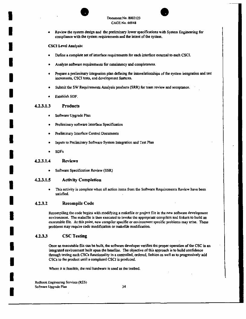
4.23.2 Recompile Code
Recompiling the code begins with modifying a makefile or project file in the new software development environment. The makefile is then executed to invoke the appropriate compilers and linkers to build an executable file. At this point, new compiler specific or environment specific problems may arise. These problems may require code modification or makefile modification.
4.233 CSC Testing
Once an executable file can be built, the software developer verifies the proper operation of the CSC in an integrated environment built upon the baseline. The objective of this approach is to build confidence through testing each CSCs functionality in a controlled, ordered, fashion as well as to progressively add CSCs to the product until a completed CSCI is produced.
Where it is feasible, the real hardware is used as the testbed.
Redhook Engineering Services (RES) Software Upgrade Plan 34

Document No. 8002123 CAGE No. 66948
The developer shall make all necessary revisions to the software, perform all necessary retesting, update the SDFs and update the software products as needed, based on the results of unit testing.
After performing the CSC testing, the team will perform a peer review where the CSC test results are examined by one or more team members and presented. At the meeting, the reviewers will summarize the CSCs readiness for baselining with CM. Test results and peer review minutes will be kept in the appropriate SDF.
4.2.3.4 CSCI Integration and Testing
The objective of CSCI integration and testing is oriented towards the production of a baseline for CSCI testing. The activity occurs once for each CSC delivered to CSCI testing for integration with other CSCs.
Once all of the CSCs have been completely integrated and tested, a system level test will be performed to verify proper operation of the RES system. This test will use a modified version of the system ATP procedure. It will verify that all existing features still work correctly and that the new changes are verified. The following products are generated as a result of CSCI Integration and Testing:
b2 b7E
At the successful completion of the integration effort, the updated CSCs, the CSCIs, test software, and test scripts are returned to CM. The test results are placed in the SDFs and the CSCI package is submitted for system testing.
4.2.4 Coding Standards
Refer to Redhook Coding Standards document in Appendix A and Appendix B.
Redhook Engineering Services (RES) Software Upgrade Plan 35

Document No. 8002123 CAGE No. 66948
5. ACCEPTANCE TESTING (ATP) 5.1 Organization and Resources
Depending upon the task, the S/W engineer or a person from System Integration/Test will have responsibility for acceptance testing of the task. SCM and SQA participate in the ATP as described in Sections 6.0 and 7.0.
5.2 Test Approach/Philosophy
The acceptance test (ATP) shall be conducted in the following steps:
o Pretest examination of all equipment with the test configuration, all associated documentation, and all supporting simulators/test equipment.
o System test including all test cases defined for the test period.
On this program, all formal testing will be performed either at the CSCI level or at the system level using redlined modified test procedures. The test procedures used will be updated versions of the procedures from the original development program. The updates will cover the testing required to verify the new features added and the corrections made during this program. The test procedure will contain a matrix showing which software modules are tested by each system test.
As a part of system engineering certification and/or recertification, the software control items requiring changes and/or modifications shall be entered into via proper configuration control processes. Prior to the start or restart of ATP, the software programs will be delivered from SCM to the engineer performing the test. This engineer shall be responsible for and shall certify that there were no unauthorized changes to the software during the test period.
Redhook Engineering Services (RES) Software Upgrade Plan 36

Document No. 8002123 CAGENo.W948
6. SOFTWARE QUALITY ASSURANCE 6.1 Scope
6.1.1 Identification This section describes the Redhook Engineering Services (RES) Software Quality Assurance (SQA) program to be used during the upgrade phase of computer software, firmware, and related documentation for the Redhook Engineering Services program.
6.1.2 Document Overview This section describes the Software Quality program which will be used on the Redhook . Engineering Services program to assure that Customer contractual requirements and Harris internal requirements are satisfied. This Software Quality Program Plan (SQPP), Section 6.0, is produced in accordance with the guidelines of D1-QCIC-80572 and complies with applicable internal Harris procedures.
The Software Quality function provides an independent review, analysis, and audit of the software maintenance and test activities associated with this program.
6.13 Relationship to Other Plans Audit records for all audits described in this SQPP are detailed in the appendices of the Harris GCSD Software Quality Engineering Handbook. Information contained in the SUP and SCMP is used to tailor these audit records to program specifics prior to the audit. The audit records and audit results are maintained in the Redhook Engineering Services Software Quality records for control purposes.
6.1.4 Referenced Internal Documents
The latest revision of these documents as of the release date of this plan should be utilized in application of this plan:
CSD-411 -001 Software Engineering Manual (SEM)
To obtain a copy of Harris publications, contact the Lead Contract Administrator, Harris Government Communications Systems Division, PO Box 91000, Melbourne, Florida, 32902.
Redhook Engineering Services (RES) Software Upgrade Plan 37

Document No. 8002123 CAGE No. 66948
62 Organization and Resources
6.2.1 Organization The Quality Assurance Department within GCSD is responsible for performing the software quality evaluation tasks for the program. Quality Assurance functionally reports to GCSD's Systems Assurance Manager. The Manager then reports to the division's VP/General Manager. This line of responsibility provides the Quality Assurance Department with direct and unimpeded access to top management for resolving quality related problems and enforcement of quality policies and procedures. The Quality Assurance department has the responsibility and organizational freedom to recognize and assess quality problems and to initiate, recommend, and provide solutions.
A Software Quality Engineer (SQE) is assigned to the Redhook Program and will report on a functional level to the Program Manager. The SQE reports administratively up through their management to provide independent assessment. The SQE is on the same reporting level as ail other Redhook functional groups (i.e., System Engineering, Software Project Engineer, etc.), therefore having the authority to act as an effective part of the management reporting system. The SQE can escalate any problems or issues to Harris GCSD top management through the independent organization structure of the Quality Assurance Department via the Quality Assurance Engineering Manager.
6.2.2 Personnel A SQE will be assigned to support the program from start-up through sell-off. This SQE is assigned to the RES Program with the approval of the Director of Quality Assurance and the RES Program Manager. The SQE is responsible for the operation of the software quality assurance program. The SQE must be familiar with all applicable Military and DoD standards, software engineering development standards, languages, methodologies, and all quality assurance software standard operating practices and procedures. In addition, the SQE must have a firm understanding of all phases of the software development cycle including design, development, integration, and test.
6.3 Software Quality Program Procedures, Tools, and Records
63.1 Procedures This plan, along with the Harris CSD Software Engineering Manual (SEM), will be used to evaluate the quality of the Redhook Engineering Services (RES) Program software and associated documentation. The SEM identifies the rules, techniques, and methodologies which will be used to satisfy the Software Quality requirements on the program. In the event of a conflict between the contents of this SQPP and the Harris CSD SEM, the contents of this SQPP takes precedence. Table 6.3.1 contains a cross reference of the paragraphs described in this document to the SQE Handbook procedures.
63.1.1 Evaluation of Documentation
Quality Assurance will evaluate all draft and fmal software documents and any changes to released software documentation prior to the formal release of the documents. Documents are evaluated for format, conformity to technical requirements, understandability, and accuracy. Approval of documentation will be withheld until resolution of noted discrepancies is obtained. Required approvals, including Quality Assurance, will be obtained before the document is formally released in order to establish a formal configuration baseline. Approved and released
Redhook Software
Engineering Services (RES) Upgrade Plan 38

Document No. 8002123 CAGE No. 66948
documents will be controlled in accordance with Section 7.0, Software Configuration Management Plan (SCMP).
Document evaluation records are discussed in Section 6.3.2, Software Quality Records.
Table 63.1. Cross Reference Compliance Matrix SQPP Paragraph
6.3.1.1 6.3.1.2.2 6.3.1.2.3 6.3.1.3 6.3.1.4 6.3.1.5 6.3.1.6 6.3.1.7 6.3.1.8 6.3.1.9 6.3.1.10 6.3.1.11 6.3.1.12
6.3.2
SQPP Paragraph Title
Evaluation of Documentation Software Upgrade Audits Software Configuration Management/Library Audits Documentation and Media Distribution Evaluation of Storage and Handling Corrective Action System Formal Reviews Walkthroughs Certification and Software Acceptance Evaluation of Non-deliverable Software Evaluation of Software Testing Control of Deliverable and Non-deliverable Tools Firmware Control Software Quality Records
Section Number
6 10 11 11 11
4,11,13 8 5 14
12,16 7 16 14 3
6.3.1.2 Evaluation of Software and Configuration Management On-going evaluations, via the audits described in the following subparagraphs, will be performed on all software to assure that the software complies with the SUP and Harris Internal Procedures. These audits are based upon written procedures and performed in a checklist format. Audits are performed on a quarterly basis to determine compliance with requirements established in specifications, plans, and procedures. Audit reports are discussed in Section 6.3.2, Software Quality Records.
6.3.1.2.1 Software Upgrades and Enhancements Software Quality Engineer (SQE) will play an integral role in the upgrading and enhancement of the existing software baselines. SQE will be a member of the SRB as a signature member which is empowered with reviewing/approving changes to the delivered software. In particular, SQE will review code changes referenced in the Software Change Report (SCR) via results of peer walkthroughs, track requirements changes, and witness/monitor upgrades/enhancements during acceptance test sell-off (refer to GCSD 408-001).
Redhook Engineering Services (RES) Software Upgrade Plan 39

I I I I I I I I I I I I I I 1 I I I
Document No. 8002123 CAGE No. 66948
63.122 Software Upgrade Audits Software will perform upgrade audits at least once every quarter to ensure adherence to the SUP and interna] software practices and procedures (refer to GCSD-408-001). These audits will ensure traceability of changes through the SCR process, internal R-140 process, updating of requirements in the Requirement Specifications, evaluation of test cases, and a review of unit test results (at a minimum). Quality will also ensure that all action items are properly documented and dispositioned.
6.3.1.23 Software Configuration Management/Library Audits Quality Assurance will perform Software Configuration Management (SCM) audits to ensure compliance with the SCMP (Section 7.0) of the SUP. The SCM audits will include SCM practices, documentation and media distribution, software storage and handling, and software corrective action. The Software Development Library (SDL) will be evaluated, as a part of the SCM audit, to ensure that only authorized modifications are made to formally released software and that the methodologies and tools used are those described in the SCMP and SUP.
SCM audits will be performed at least on a quarterly basis. Prior to performing the quarterly SCM audit, the SQE will review and tailor the audit record for the Upgrade/Maintenance phase of the SQE Handbook against the current program SUP. The SQE will modify the checklist items, if required, to reflect program specific practices for the appropriate activities of the program. The audit record will be completed during the SCM audit. The Software Quality Engineer and the auditee will discuss each discrepancy and develop a recommended corrective action. A follow-up audit will be performed within 30 days of the original audit if outstanding discrepancies exist. Follow-up audit results will be documented in the audit report. Refer to the SEM, SQP 11, Software Configuration Management/Library Audits, and Appendix G of the SEM for additional information.
6 J. 1.3 Documentation and Media Distribution The program documentation and media distribution will be evaluated via the Software Configuration Management audits as described in paragraph 6.3.1.2.3 in order to assure that only the latest version of the documentation and software is used.
6.3.1.4 Evaluation of Storage and Handling The evaluation of storage and handling of media and documentation will focus on the safeguards used to protect the documentation, media, and files. The implementation of storage and handling procedures will be evaluated as part of the quarterly audit of die Software Configuration Management as described in paragraph 6.3.1.2.3.
6.3.1.5 Corrective Action System A corrective action system will assure that problems, discrepancies, deficiencies, and adverse trends are identified, reported, investigated, analyzed, and corrected in a timely manner. Problem types will be analyzed, corrective action will be tracked to completion, and the implementation of the corrective action verified (reference Section 7.0, SCMP).
Problems, discrepancies or deficiencies identified in baselined documentation or software, will be noted in the Task Logbook during integration and on an R-140 during dry-run ATP. Any software defects, problems, or deficiencies found during acceptance testing will be denoted on an SCR and resolved via the Software Review Board (SRB). The SRB process is detailed more in
Redhook Engineering Services (RES) Software Upgrade Plan 40

Document No. 8002123 CAGE No. 66948
Section 7.0. Proper functioning of the SRB will be evaluated by the SQE, serving as a SRB signature member as described in the SEM, Section 13, Software Quality Configuration Control Board Responsibility. The SQE will participate as a supporting member of the SRB when software documentation is involved.
The software corrective action system for baselined software and documentation will be evaluated as part of the quarterly Software Configuration Management audit.
6.3.1.6 Formal Reviews None are planned.
6.3.1.7 Walkthroughs Peer group inspections of design and code for upgrades and enhancements are participated in by the SQE. The Systems Engineering and Software Development organizations are responsible for accomplishing the walkthroughs and resolving noted discrepancies. The SQE may participate in these walkthroughs as a team member and will monitor the activity as a minimum. Discrepancies noted by the SQE will be resolved prior to software acceptance. Completion of walkthrough action items are verified by the SQE as part of the Software Upgrade audits. Records of walkthroughs are maintained by the responsible organization.
6.3.1.8 Certification and Software Acceptance
Quality Assurance will assure software products comply with contractual requirements prior to delivery to the customer. The SQE will review and accept each software submittal to Configuration Management by verifying mat the software is the proper version/revision, is complete, has been appropriately tested, and has the necessary supporting documenta'ion such as a directory, completed SCR form, or Software Assembly Document (SAD). After successful completion, the SQE will sign the baselining form signifying Quality Assurance acceptance and will stamp and date the software products.
After the software is accepted and is ready for delivery, the SQE will perform the following:
o witness copying of the Configuration Management controlled master to generate deliverable media
o seal the deliverable media
o verify the media label conforms to the contract requirements
o verify the media label information is correct
o stamp and date the seal on the media
6.3.1.9 Evaluation of Non-Deliverable Software The SQE will assure that non-deliverable software is CM controlled and documented, if needed. Non-deliverable software includes test software and Harris generated tools. The SQE will review the software documentation during the software upgrade audits for adequacy in describing the functional description and design, and that it is in conformance with the established guidelines for form and format. All non-deliverable software is controlled by Software Configuration Management and verified by the SQE during the Configuration Management audit. The SQE will ensure the proper documentation exists and that it is controlled and maintained in accordance with the SCMP, Section 7.0.
Redhook Engineering Services (RES) Software Upgrade Plan 41

Document No. 8002123 CAGE No. 66948
63.1.10 Evaluation of Software Testing The SQE will evaluate unit test cases, procedures, and results as part of the Software Upgrade audits. The SQE will also evaluate Computer Software Component (CSC) integration test cases, procedures, and results as part of the SCMP audits. SQE will witness/monitor specific build tests of critical functions. Verification of proper CSC Integration testing is performed by the SQE as part of the Software Upgrade audit.
The SQE will monitor/witness formal acceptance and regression testing to ensure the software is verified to the current test documentation. After the test data is recorded into the test procedure, the pages will be stamped by Quality Assurance to certify the authenticity of the data.
63.1.11 Control of Deliverable and Non-deliverable Tools The SQE will play an active role in the acceptance and certification of Program deliverable and non-deliverable tools. In particular, all deliverable tools will follow the formal SCR process as outlined in the SUP. Non-deliverable tools will be validated by the SQE prior to acceptance. Developmental tools are customer driven while the non-deliverable tools are to be used as an aid to the developer to improve his/her efficiency.
63.1.12 Firmware Control The SQE will prepare and maintain Work Order Flow Tags (WOFTs) to program firmware. The SQE or his/her representative will complete the WOFT during programming to ensure all steps are completed successfully. These steps will ensure that the correct software is used and the devices are properly labeled and controlled.
63.2 Software Quality Records The SQE will prepare and maintain software quality records of each audit performed. These records will identify the date of the evaluation, the evaluation participants, the items or activities evaluated, the objective of the evaluation, and detected problems/corrective action. Upon completion, the report will be issued to the audited organization. The quality records will be retained by the SQE for a minimum of four years after completion of the program. AH quality records shall be made available at the GCSD facility to customer representatives upon request.
Reports will be issued for all documentation evaluation, SCMP audits, SUP audits, and pre-acceptance inspection audits. Reports will identify the problems, deficiencies and discrepancies found, the corrective action (if required), and the individual(s) responsible for providing corrective action and when the correction actions is due or will be implemented. Reports will be closed when all discrepancies have been resolved.
Redhook Engineering Services (RES) Software Upgrade Plan 42

9 © Document No. 8002123
CAGE No. 66948
7. SOFTWARE CONFIGURATION MANAGEMENT PLAN (SCMP) 7.1 Scope
7.1.1 Identification This software configuration management section describes the organization, policies, procedures, and methodology that will be used in implementing software configuration management disciplines and controls to identify, control, and account for the configuration item (CI) during the Redhook Engineering Services (RES) program. This plan encompasses the requirements for configuration identification, configuration control, configuration status accounting, interface control, reviews and audits.
7.1.2 Document Overview Harris has established procedures for Software Configuration Management that are fully compliant with contract requirements and SE1 Level 3 standards. Configuration Management disciplines will be enforced throughout the program to ensure effective configuration identification, control, and accounting of all hardware and software changes. Emphasis is placed on change control procedures for baseline documents, implementation status of changes, and control.
7.1.3 Referenced Internal Documents
CSD-411 -001 Software Engineering Manual, Chapter 5, Software Configuration
Management
• Software Vault Procedures
• Software Release Procedure
• Document Change Control Procedure
• Software Change Control Procedure
7.2 Organization and Resources
7.2.1 Organization Software Configuration Management (SCM) functionally reports to GCSD's Systems Assurance Manager. The Manager then reports to the division's VP/General Manager. SCM is responsible to the program manager for an effective and responsive CM program that keeps all SCM procedures current and implemented to ensure fulfillment of SCM contractual commitments and SEI Level 3 requirements.
The SCM manager is responsible for the operation of the SWCM activities on the program, identification, control, status accounting, audits, and Software Review Board (SRB) functions.
7.2.2 Personnel A CM person will be assigned to support the program from start-up to sell-off. SCM is responsible for assuring that the configuration of all deliverable and non-deliverable software is fully identified and that a clear audit trail to source documents is maintained. Specifically, SCM:
Redhook Engineering Services (RES) Software Upgrade Plan 43

Document No. 8002123 CAGE No. 66948
o Makes software data available to support the program
o Assures that configuration data of all program software is maintained at all times through SCM random internal audits
o Administers software change incorporation
o Exercises software change control
o Creation of deliverable software
o Controls program software, COTS software, and other non-deliverable software. (Firmware is considered the same as software).
o Maintains library for software, tools and documents relevant to software; at a minimum, a list as to the location of these tools will be kept by SCM.
73 Process
73.1 Software Development Library (SDL) The Software Development Library (SDL) is the repository for all software design and requirements information. See Section 3.7.1 for a listing of SDL items. The SunPro Teamware (SCCS) configuration management tool, in conjunction with Harris developed tools and data bases, are used for all phases of configuration management and problem tracking.
All developers will use the SDL and the tools that support it for all upgrades activities.
7.3.2 Software Change Report (SCR) The Software Change Report (SCR) is the means by which all discrepancies or required changes are made to the baseline software (reference Figures 7.3.2-1 and 7.3.2-2, Software Change Report). All tasks initiated by the Sponsor will have an SCR generated which will be reviewed/closed out at the Test Readiness Review (XRR). Additional SCR's may be generated during ATP which would require SRB approval prior to task close-out. SCM tracts and reports the status of all SCR's. Once an SCR is opened for any reason, it must be reviewed by the Software Review Board (SRB) in order to close out all action items and before it can be incorporated into the software baseline.
Three total types of discrepancies may be noted: discrepancy in the Task Logbook, R-140 discrepancy or as an SCR. Reference Section 3.8, Corrective Action Process, for additional detail.
7.3.3 Software Review Board (SRB)/Configuration Control Board (CCB)
The SRB consists of technical team members who are responsible for the final review of all software products prior to formal release. For the RES program, the board consists of the SWPE, Task Leader, SE, SQA and SCM at a minimum.
If an SCR is found to affect areas outside of software, then the item goes to a Configuration Control Board (CCB) where it will be evaluated/dispositioned by additional functional experts. The CCB consists of PM, SE, SWPE, Task Leader, SQA, SCM and other functional experts as needed.
Redhook Engineering Services (RES) Software Upgrade Plan 44

Document No. 8002123 CAGE No. 66948
7.4 Status Accounting SCM is responsible for the collection, recording, processing, and maintenance of all software configuration status accounting records. Status accounting records are updated each time an SCR is submitted to SCM.
This ensures that the status accounting reports always contain the most current information and accurately reflect the approved baseline and changes. Status accounting records will be established to list and track all software and associated documentation and SCR's.
7.4.1 Software Configuration Status Reports Status accounting records will be established as required to list and track the following items:
a. Software media (SCM controlled disk packs, diskettes and tapes) at program completion.
b. SCR's
c. Software Baseline update records
Redhook Engineering Services (RES) Software Upgrade Plan 45

Document No. 8002123 CAGE No. 66948
SCR*
SOFTWARE CHANGE REQUEST (SCR) | | Discrepancy | | Change j | Enhancement PAGE OF
INITIAL REQUEST Originator Name/Date:
Project*
Description of Discrepancy/Change/Enhancement:
ANALYSIS Assignee: Requirements Affected: Results:
RECOMMENDED SOLUTION(s)
Authorization Approval:
IMPLEMENTED SOLUTION Description:
Regression Tests:
Implemented By: Filaroocumem Title: ID
CLOSURE Disposition: Closure Approval:
Pate Systems Eng. Project Enq. SCM SWEng.
Data:
CSCI:
Product*: Phase Detected:
Priority:
Date:
Date: Verified By: CSCI Rev Fa/Doc Rev File/Document T New/Old New/Old
Sianature
Baseline Affected:
System Test SQA Customer
Media* HW Station ID:
Category: Class Tvoe:
Tartjet Baseline:
Analysis Hours:
Correction Hours:
Date: Hie: ID CSCI Rev File/Doe Rev
New/Ok) New/Old
Date Sionature
H-2080F (06V95)
Figure 7.3.2-1 Software Change Report (Sheet 1 of 2)
Redhook Engineering Services (RES) Software Upgrade Plan 46

1 I 1 I I
Document No. 8002123 CAGE No. 66948
SOFTWARE CHANGE REPORT (SCR) INSTRUCTIONS INITIAL REQUEST
SCR *: SCR assigned number Originator Name/Date: SCR originator and date disaepancy/change/enhancement reported Project #: JA # of program Product tt: Software product part number (if applicable) Media #: Software media part number (if applicable) Description of Otscrepancy/ChangefEnhancemerrt Describe, in full, symptoms(a) of discrepancy, need for change or enhancemeni Phase Detected: Enter phase where discrepancy/change/enhancement detected or requested:
PD-Preliminary Design Ofi-Detailed Oesign CSU-CSU Testing C^c i -CSClTwt inT ST-System Testing HU-MaintenancertJograde
HW Station ID: Equipment on which the discrepancy/change/enhancement was identified, if applicable ANALYSIS
Assignee Name/Date: Name and date of person assigned for analysis Priority: Enter one of the following: 1 Prevents the accomplishment of an operation or mission essential capability or jeopardizes safety, security or other requirements
designated "critical*. 2 Adversely affects- the accomplishment of an operational or mission essential capability and no workaround solution is known or ~ technical cost or schedule riskstotheprojectortolife cycle support of the system, and no workaround solution is known. 3 Adversely affects: the accomplishment of an operational or mission essential eapaWity but a workaround solution is known or " technical cost or schedule risks to the project or to life cycle of the system, but a workaround solution is known. 4 Results in: user/operation inconvenience or annoyance but does not affect a required operational or mission essential capability or " inconvenience or annoyance for development or support personnel but does not prevent the accomplishment of those
responsibilities. 9 Any c*er affect. Category: Select the first product affected by the SCR to determine whether a discrepancy, change, or enhancement, assuming all subsequent baseiined products will also be affected: a Concept—the operational concept—implies system change b System Requirements (functional baseline)—implies system enhancement e Software Requirements (allocated baseline)—implies software enhancement g Design the design of the system or software—implies software change/discrepancy a Plans—one of the plans developed tor the program f Code—the software code—implies software change/discrepancy g Database/data file—a database or data file—implies software change/discrepancy h Test information—test plans, test description—implies change/discrepancy T Manuals—the user, operator or support manuals—implies change/discrepancy j Other—other software products Class Type: Enter one of the following
Class! ECP required Class HJaj—Customer concurrence not required Class HlbJ—Customer concurrence required Requirements Affected: List requirements affected Results: Describe, in detail, results of analysis Recommended Solution: List recommended solutiorts(s) CSCl Name: List name of CSCl(s) affected Target Baseline: Baseline version change in which solution will be implemented Description: Describe, in detail, activities to be performed to solve discrepancy/changc'enhancement Authorization: Approval signature Date: Enter date of authorization Analysis Hours: Enter total number of hours spent on analysis
IMPLEMENTED SOLUTION Correction Hours: Enter total number of hours spent on implementing solution Description: Describe, in detail, activities performed to solve dtserepartcy/criange/eririancemertt Regression Tests: List specific test(S) to be performed to verify incorporation of solution implemented By—Name/Date: Person who implemented recommended solution and date Verified By—Name/Date: Person who verified solution incorporation and date File NamefDocurnent Title: List of file name(s)/document(s) affected by incorporation with new/old revision
CLOSURE Disposition: List one of the following for status of SCR: closed, deferred, rejected Baseline Affected: Baseline version that change has been implemented in, or is deferred to Closure Approval: Closure signatures/dates of SCCB personnel
H-2080B (08/95)
Figure 73.2-2 Software Change Report (Sheet 2 of 2)
Redhook Engineering Services (RES) Software Upgrade Plan 47

. Document No. 8002123 CAGE No. 66948
7.4.1.1 Open SCR Status The Open SCR Status Report will contain the following items as a minimum:
a. Identification number
b. CSCI Name/Software Title
c. Category
d. Date opened
e. Approval status
f. Subject
g- Type
h. Date closed
7.4.1.2 Software Status Reports SCM will generate an SCR Summary Report quarterly during the enhancement program. The information for each report will be extracted from the applicable logs maintained by SCM and will be distributed to Program Management, Systems Engineering, and Software Quality Assurance (SQA). SCM will maintain copies of all reports generated for future reference and traceability. The SCR Summary Report will contain the following information:
a. Total number of SCR's
b. Number of open SCR's
c. Number of closed SCR's
d. Number of SCR's with outstanding documentation updates
7.5 Storage The CM file cabinet will consist of a secure storage area controlled by CM/Data Management.
When software is ready to be placed in the CM cabinet prior to delivery, the following must be provided in accordance with the SEM, Chapter S:
a. Media containing software certified by SQA. No requirements for QA certification of COTS software
b. Directory of media
c. Submittal form
The media must be labeled as follows:
a. Media number
b. Serial number
c. Volume number
d. Version level of software
e. Media date
f. Program name
Redhook Engineering Services (RES) Software Upgrade Plan 48

Document No. 8002123 CAGE No. 66948
g. Revision level of software
h. Type of software (test, F/W, tools...) i. Title of software
j . Vault location
k. Part number
Media number is assigned by SCM, a Media number consists of the 4-digit JA number from the development program (1726) with a unique 4-digit number separated by a hyphen. The unique 4-digit number is assigned in ascending order, starting with the number 100.
The media with serial number 1 will always be considered the CM master copy. Master copies cannot be loaned out or used without CM or QA supervision. Media with serial number 2 is stored in a second location. Media with serial numbers 3 and above are for use by the program.
SCM will maintain at least two copies of each controlled media for the program. One copy will be available to die program team under CM or QA supervision. Additional controlled copies can be made for extended program usage.
7.6 Delivery of Software Delivery applies to Harris Software/Firmware and Vendor software being used in the RES program and may include source code, include files, object, image files, compile and link command files, and run time command/data files. SCM will build an executable to ensure all required files are present, where possible. Firmware will be accompanied by a build document detailing PROM creation procedures.
Redhook Engineering Services (RES) Software Upgrade Plan 49

Document No. 8002123 CAGE No. 66948
8. LIST OF ACRONYMS AND ABBREVIATIONS AMH
ATP BAR CCB CM CMP COTS
CSCI
CSC CSU DM DOD GCSD
PCS PDL PDR PDU PE PM PROM
RES SAD SCM SCMP
SCR SDF SDL SE SLOC
SRB SUP SQA SQP SQPP
SSR SUP
Audio Monitor Head
Acceptance Test Procedure
Business Area Review
Configuration Control Board
Configuration Management
Configuration Management Policy
Commercial Off-The-Shelf
Computer Software Configuration Item
Computer Software Component
Computer Software Unit
Data Management
Department of Defense
Government Communication Systems Division
Project Control System
Program Design Language
Preliminary Design Review
Processing Distribution Unit
Project Engineer
Program Manager
Programmable Read-Only Memory
Redhook Engineering Services
Software Assembly Document (or VDD)
Software Configuration Management
Software Configuration Management Plan
Software Change Request
Software Development File / Folder
Software Development Library
System Engineer
Software Lines of Code
Software Review Board
Software Upgrade Plan
Software Quality Assurance
Software Quality Plan
Software Quality Program Plan
Software Specification Review
Software Upgrade Plan
Redhook Engineering Services (RES) Software Upgrade Plan 50

Document No. 8002123 CAGE No. 66948
SWPE Software Project Engineer
TRR Test Readiness Review
WOFT Work Order Flow Tag
Additional acronyms and definitions can be found in the SQE Handbook, SQP 17, Software Quality Terms.
Redhook Engineering Services (RES) Software Upgrade Plan 51

Document No. 8002123 CAGE No. 66948
APPENDIX A
REDHOOK CODING STANDARDS
Workstation and PDU
Redhook Engineering Services (RES) Software Upgrade Plan 52

Document No. 8002123 CAGE No. 66948
ttsdhoolt S o W w w D < W Q H O P I N G !Df Consols $Qtt*/on: Sottwon CodlnQ sronocvtt
Software Cooing Standards
Tnese guidelines descnbe nommg. formatting, cooing, and documen-tation conventions to &e followed wnSe constructing Redhock wortato Hon software-
b2 b7E
Naming Conventions:
Identifier Names
File Names
FoniMirsng Conventions
1»» Oaenaek KXonatawjn SortwM H M H I T ,n - •"iinfTTii
b 6 b7C
Reilhwk Engineering Services (RES) Software Upgrade Plan 53

Document No. 8002123 CAGE No. 66948
Bttfwofc Sofntote P#wy> Operator Consow Software: Software Cocing Sfancaras
indented Text Mode tor .ft F3es
b2 b7E
Folding Minor Mode for .ft FSes
Redhcok.el
TAsf fS t f iOM eVUfUHJftOn SoffwQTO tt«anJ * » a a l * ^ B d a t e
Redhook Engineering Services (RES) Software Upgrade Plan 54
b6 b7C

I Document No. 8002123 CAGE No. 66948
todhook Softwora D^ggn Operator Console Software: Sofiwora Coding Srcnoeroi
Redhook.eJ defines the following macros:
b2 b7E
TrSS I 1 » I I Mo.lWft
Redhook Engineering Services (RES) Software Upgrade Plan 55
b6 b7C

Document No. 8002123 CAGE No. 66948
B#dhook SofrouK P#cyi Opfotor Console ScftwoTQ: Soffwqq Coding Stondoroi
b2 b7E
Une Length
Indenting
M m I.I • M-Mw-IWS
•c m*
Redhuok Engineering Services (RES) Software Upgrade Plan
b6 b7C
56

* Document No. 8002123 CAGE No. 66948
HHI I - IH I " • — " - " ws 9sosiooK WBHSIORQA sotKi^n
way t!5n[
b6 b7C
Retihook Engineering Services (RES) Software Upgrade Plan 57

I I B fl
Bedhook Software Design
Document No. 8002123 CAGE No. 66948
Ooerorcr Coraow Software: Software Coding StonoaS
Each header fie defines a symbol to prevent multiple jnciusjcns. Tfee. symbol a on uorarl
Don' t include header Ales when not necessary. If only pointers or references to the object are needed, it suffices to simply declare the class. The doss declaration starts inT PubOc. protected, and private keywords
5: The keywords virtual end static start ir| start in
Consttuctors. other member function names, ana data mem-ber identifiers start i r i ^ ^ ^ ^ ^ I Return types stdrt < n | ^ ^ ^ ^ ^
b2 b7E
t The const keyword is considered part of the return type here, and starts tt^^^^^^^^^^J Everything hongs out in|
liifijDctaniceiy if the - on the destructor name ami
in* H.
Redhouk Engineering Services (RES) Software Upgrade Plan
b6 b7C
58
Document No. 8002123 CAGE No. 66948
KocJhoofc Soffwom DMw0n Operator Consow Software; Software Coding StonodrS
b2 b7E
rn*
RedhiK)k Engineering Services (RES) Software Upgrade Plan
b6 b7C
59

Document No. 8002123 CAGE No. 66948
B#dhoolt SoffWQHi O^^jjit OoerarorCorao»Softwar»:Soltwffl»CodnoSranaffCi
b2 b7E
v*m i l • 1**w-t«»
•T Tha
b 6 b7C
Reiihitok Engineering Services (RES) Software Upgrade Plan 60

Document No. 8002123 CAGE No. 66948
RvohookSonwQTODMjQn Operator Console Seftwara: Softwo* Cooing Standards
b2 b7E
f h # flhMSfMOfe H l ^ W W O r t SQttotlCtQ *=€
b6 b7C
Redhook Engineering Services (RES) Software Upgrade Plan

Document No. 8002123 CAGE No. 66948
todtwwlc Soft QUI o Dwign 10 Ooerate* Comow Software: Software Coowg Sfonaaras
b2 b7E
8: 9:
10: I I :
f*• a+anoa* (MoMananan Sonwara i r«arl iSL.
b 6 b7C
Redhnok Engineering Services (RES) Software Upsr«fc Plan 62
Document No. 8002123 CAGE No. 66948
todhoofc Softwqf OWIQI I n 6pa>otorConio»SoTtwq8:ScWwc»Codirigaijiiduiai
b2 b7E
• W W
b 6 b7C
Reiihmik Engineering Services (RES> Software Upsrade Plan 63

Document No. 8002123 CAGE No. 66948
Badhook Software Parian 12 Operator Corioie Software: software Coding Standards
b2 b7E
RedhtHik Engineering Services (RES) Software Upcrade Plan
b 6 b7C
64

Document No. 8002123 CAGE No. 66948
BXhoofc Software D—Ign 13 Ooeretor Console Software: Software Cofiino Standara
Here ore how typical n constructs should be done:
b2 b7E
"[ Th# wtonoM Wofttt0f*on Sofnwot ft
Reiihouk Engineering Services (RES) Software Upgrade Plan 65
b 6 b7C

Document No. 8002'23 CAGE No. 66948
B^ioofc Soffwaw Dwlgn_ U Co0.'crer Consoio Sonwora: Soffwaw Coding srcrwarw
b2 b7E
7r« flMnQO> wamttiMn JoAwm • <Nn| ,n ltiMnilTin
ReUhnnk Engineering Services (RES) Software Upgrade Plan
b6 b7C
66

Document No. 8002123 CAGE No. 66W8
tadhook Softwof Doicjn 15 Coersror Consow Software: Spnwam Coding Standards '
b2 b7E
ln« aaanset wonmsnon scrrwof* i«on . i ^ M » - i » a >
b 6 b7C
Redhook Engineerins Services (RES> Software Upgrade Plan 67

* Document No. 8002123
CAGE No. 66948
todhook Class library Operator Console Software: Oes Sescnctiora^ J b2
b7E
NOfTM
b2 b7E
tha oeshucfor dcs&ovi a^^^^^T^iSTquagiwnditeiwiunltwgiiDnewTia.
i w —o«ao« lummtM1' ienwg* V n y I I • I, ***--'"* r
b6 b7C
Redhook Engineering Services (RES) Software Upgrade Plan 68

Document No. 8002123 CAGE No. 66948
b2 b7E
R+dhook Oon Ubnay i? OpafOWrCOfH0laSeflWQra:ClQM0e«cnpwb?51
Public M w n b f Function* jb j j£
i^maf>^ovaiiLKjjiniao^»iw«oparowrr*cai*aj»MjL»^^ liinlain oamtar • • L ^ Z ^ ^ ^ Z ^ ^ ^ ^ J 0 " " " "
lha iUneaon e o i r e e S s ^ ^ ^ ^ ^ ^ S S i S * u» * may aw aquatv warel or wnether oneftesromoioss ond ma omaf ona doasvt.
Protected Mwnbw Functions b2
Privets Mombor Functions . „ _ b7E Public Data Mwnbors
Protected Data Mombora
Private Data Motnboa
' I lha octo «em art ui unow now * iy wert ma OBoer raaly a. on a icaa of 0 to 1.
UnctaMlfted Members
Iftnon I I • 1*Mar.l9W Th# QvQFtOOfc WOilOWWW* SofassWS raonJ
b6 b7C
Redhook Engineering Services (RES) Software Upgrade Plan 69

Document No. 8002123 CAGE No. 66948
APPENDIX B
REDHOOK CODING STANDARDS
Bridge
Redhook Engineering Services (RES) Software Upgrade Plan

Document No. 8002123 CAGE No. 66948
C Programming Language Style Guide 1. INTRODUCTION This document lists the guidelines and describes the standards and procedures to be applied during the code and test phase of the RES software upgrade effort.
2. CODING GUIDELINES, STANDARDS AND PROCEDURES This section contains the guidelines, standards, and procedures for the coding phase.
In this Appendix, the terms "unit" and "function" refer to a C function, and may be used interchangeably. The term "file" refers to a text file containing one or more units (or functions) preceded by a Unit Header.
2.1. General Guidelines The following are general guidelines which apply to the coding phase. Items 1-6 are very general. Items 7-29 are general rules which are applicable to code written in any of the languages used on the RES program. Items 30-35 apply more directly to the organization of the data declarations and definitions for the code.
2.1.1. Language A structured High-Order Language (HOL) is to be used where possible. The HOL used is the C programming language. If the HOL proves to be insufficient for a part of the application, then the appropriate assembly language(s) may be used, with consensus approval. Most C compilers supply in-line assemblers, which may be used.
2.1.2. Structured techniques All HOL software is to be developed using structured coding techniques as implemented in the C language. Use of the goto and continue keywords is prohibited. Other C language statements which simulate branching are addressed later in this Appendix.
2.1.3. Naming All names of components, units, and program variables are to be mnemonically descriptive of the entity to which they apply. Components, units, and data are to provide direct linkage to the appropriate PDL description. Detailed naming standards are discussed later in this Appendix.
2.1.4. Comments Sufficient comments must be included to clarify all source code. Groups of source statements performing a logical function are offset by comment statements describing the function performed.
2.1.5. Headers Each unit must commence with a Unit Header. Unit Headers are fully described in Appendix A.
Redhook Engineering Services (RES) Software Upgrade Plan 71

Document No. 8002123 CAGE No. 66948
2.1.6. Function length Functions should contain at most 150 SLOC. An average length of 30 to 50 lines per function is encouraged.
2.1.7. Function unity Each unit will perform a single well-defined function.
2.1.8. File unity The following guidelines may be used in placing multiple units within a file:
o The functions share variables which are of no use to other functions not in that file.
o The functions are logically related so that grouping them would not cause confusion.
o Object-oriented issues
2.1.9. Structure of Functions Each function must have a single entry point and a single exit point. f l i f t I n . H n p r « m m P n k
> e e JU.)
b2 b7E
Redhook Engineering Services (RES) Software Upgrade Plan 72

I I
Document No. 8002123 CAGE No. 66948
2.1.11. Global Variables
b2 b7E
Redhook Engineering Services (RES) Software Upgrade Plan 73

Document No. 8002123 CAGE No. 66948
b2 b7E
2.1.12. Static Variables
2.1.13. Error Handling Upon encountering an error which does not permit further execution of the function, the function must free any resources it has acquired before it returns.
Every function must perform adequate error-checking and error code reporting. This issue is addressed in more detail in the SRS.
Redhook Engineering Services (RES) Software Upgrade Plan 74

Document No. 8002123 CAGE No. 66948
2.1.14. Limit checking Limit checking must be performed on values as they are calculated or received from a source which is not guaranteed to have checked the limits. For example, a function need not check calling parameters if the design of the calling function guarantees the value to be within range. But, if a value is retrieved from a field of a database which does not have those limits defined, then the value must be checked if it is to be passed or used. The function description must discuss and explain the limit checking accomplished by the function.
If a variable value does not fall within the specified limits, appropriate error action must be taken. The domain of all variables must be specified during detailed design and declared during implementation. Examples of variables which must be range-checked'are:
o Array subscripts.
o Computations for which there is a known invalid domain (e.g., a percent value of less than zero or greater than 100 may be considered invalid).
2.1.15. Loops Loop termination must be guaranteed.
2.1.16. Indentation
b 2 b 7 E
Redhook Engineering Services (RES) Software Upgrade Plan 75

Document No. 8002123 CAGE No. 66948
2.1.17. Indentation of multi-line statements
b2 b7E
Redhook Engineering Services (RES) Software Upgrade Plan 76

Document No. 8002123 CAGE No. 66948
2.1.18. Indentation of list items
b2 b7E
Redhook Engineering Services (RES) Software Upgrade Plan 77

Document No. 8002123 CAGE No. 66948
2.1.19. Indentation of for loops
2.1.20. Format of operators
-b2 b7E
Redhook Engineering Services (RES) Software Upgrade Plan 78

Document No. 8002123 CAGE No. 66948
2.1.21. Parentheses
b 2 b 7 E
2.1.22. Commenting of block structures
2.1.23. #include file headers
2.1.24. Coding templates
Redhook Engineering Services (RES) Software Upgrade Plan 79
Document No. 8002123 CAGE No. 66948
•
2.1.25. Alignment
2.1.26. Declaration of globals Global constants and global variables (shared between units in separate files) must be maintained separately and included in the modules which need them.
2.1J7. Constants
Redhook Engineering Services (RES) Software Upgrade Plan 80

Document No. 8002123 CAGE No. 66948
2.1.2ft. In-line comments
b2 b7E
2.1.29. Comment blocks
2.1.30. Blank lines Blank lines are permitted anywhere and are encouraged to enhance readability.
Redhook Engineering Services (RES) Software Upgrade Plan 81

2.1.31.
Document No. 8002123 CAGE No. 66948
Increment and decrement operators
Redhook Engineering Services (RES) Software Upgrade Plan 82
J

Document No. 8002123 CAGE No. 66948
2.1.32. Statement complexity
b2 b7E
Redhook Engineering Services (RES) Software Upgrade Plan 83

Document No. 8002123 CAGE No. 66948
2.1.33. Breaks in switch statements
2.1.34. Bracket placement
Redhook Engineering Services (RES) Software Upgrade Plan 84

Document No. 8002123 CAGE No. 66948
2.1J5. Breaks in other than switch statements The use of break is limited to the switch structure. The use of break to exit while, for, and do loops is discouraged but may be used subject to consensus approval.
2.1.36. Prototypes
Redhook Engineering Services (RES) Software Upgrade Plan 83

Document No. 8002123 , /-, CAGE No. 66948
b7E 2.1.37. Coding Examples
Redhook Engineering Services (RES) Software Upgrade Plan 86

Document No. 8002123 CAGE No. 66948
Redhook Engineering Services (RES) Software Upgrade Plan 87

Document No. 8002123 CAGE No. 66948
2.1.38. Data type sizes and sharing Variables should be declared keeping in mind the size of the variable type and whether the data will be shared across machine types. The following table lists the formats of the various variable types on the machines which will be used on the ReSr project. Note that this table reflects what
| jand most PC C compilers implement: this is only a subset of the ANSI C definition.
t 2 It is acceptable to share char, short, int, long, and float values across machines, provided that 7 g appropriate byte-swapping is performed; do not share double values.
2.1.39. Bit Field Definitions in Structures
Redhook Engineering Services (RES) Software Upgrade Plan

Document No. 8002123 CAGE No. 66948
For example:
b2 b7E
However, to define the identical structure on arj would be required:
Ihe following typedef
Redhook Engineering Services (RES) Software Upgrade Plan 89
Document No. 8002123 CAGE No. 66948
(Note that this is not intended to define any particular floating-point type, but is intended to serve only as an example.)
2.1.40. Use of #define to Alter C Syntax
2.1.41. Suggested Uses of Preprocessor Statements
The standard preprocessor statements which control compilation of blocks of code may be used where meaningful and necessary. Uses for conditional compilation could include:
b 2 b 7 E
Redhook Engineering Services (RES) Software Upgrade Plan 90 '

w Document No. 8002123
CAGE No. 66948
2.1.42. Standards for ^defines The following conventions should be used to indicate certain pre-compilation symbols:
2.1.43. The[__^]project f i Ie b 2 b 7 E
The following procedures should be followed regarding th< project file:
2.1.44. Handle dereferencing Data fields within a handle should always be accessed through the handle, not by setting a pointer variable to the dereferenced handle and accessing via the pointer.
b2 b7E
Redhook Engineering Services (RES) Software Upgrade Plan

Document No. 8002123 CAGE No. 66948
2.1.45. Syntax of Handle vs. pointer access Data fields within a handle should always be accessed using the following syntax:
b 2 b 7 E
Data fields within a pointer may be accessed using either of the following methods:
2.1.46. Nested #include files
Redhook Engineering Services (RES) Software Upgrade Plan 92