TRANSFER GEAR BOX - Zuki Offroad. GENERAL DESCRIPTION The transfer gear box is an auxiliary...
23
SECTION 14 TRANSFER GEAR BOX CONTENTS 14-l. GENERAL DESCRIPTION ................................. 14-2 14-2. SELECTIVE FLOWS OF TRANSFER DRIVE .................. 14-3 14-3. GEAR RATIO DATA . . . . . . . . . . . . . . . . . . . . . . . . . . . . . . . . . . . . . 14-4 14-4. TRANSFER SERVICES NOT REQUIRING TRANSFER REMOVAL . . . . . . . . . . . . . . . , . . . . . . . . . . . . . . . . . . . 14-5 14-5. REMOVAL ............................................. 14-6 14-6. DISASSEMBLY .......................................... 14-8 14-7. INSPECTION OF COMPONENTS ........................... 14-12 14-8. REASSEMBLY ......................................... 14-14 14-9. MAINTENANCE SERVICES . . . . . . . . . . . . . . . . . . . . . . . . . . . . . . . 14-22 12 TIGHTENING TORQUE . . . . . . . . . . . . . . . . . . . . . . . . . . . . . . . . . . 14-23 14-1 14-10.
Transcript of TRANSFER GEAR BOX - Zuki Offroad. GENERAL DESCRIPTION The transfer gear box is an auxiliary...

SECTION 14
TRANSFER GEAR BOX
CONTENTS
14-l. GENERAL DESCRIPTION . . . . . . . . . . . . . . . . . . . . . . . . . . . . . . . . . 14-2
14-2. SELECTIVE FLOWS OF TRANSFER DRIVE . . . . . . . . . . . . . . . . . . 14-3
14-3. GEAR RATIO DATA . . . . . . . . . . . . . . . . . . . . . . . . . . . . . . . . . . . . . 14-4
14-4. TRANSFER SERVICES NOT REQUIRINGTRANSFER REMOVAL . . . . . . . . . . . . . . . , . . . . . . . . . . . . . . . . . . . 14-5
14-5. REMOVAL . . . . . . . . . . . . . . . . . . . . . . . . . . . . . . . . . . . . . . . . . . . . . 14-6
14-6. DISASSEMBLY . . . . . . . . . . . . . . . . . . . . . . . . . . . . . . . . . . . . . . . . . . 14-8
14-7. INSPECTION OF COMPONENTS . . . . . . . . . . . . . . . . . . . . . . . . . . . 14-12
14-8. REASSEMBLY . . . . . . . . . . . . . . . . . . . . . . . . . . . . . . . . . . . . . . . . . 14-14
14-9. MAINTENANCE SERVICES . . . . . . . . . . . . . . . . . . . . . . . . . . . . . . . 14-22 12
TIGHTENING TORQUE . . . . . . . . . . . . . . . . . . . . . . . . . . . . . . . . . . 14-23
14-1
14-10.
James Oaks
Text Box
www.zukioffroad.com

14-1. GENERAL DESCRIPTION
The transfer gear box is an auxiliary transmission for on-off control of two-speed drive transmitted toboth front and rear axles concurrently and provides additional speed reductions, HIGH and LOW, for anyselection of main transmission gears.
The functions of this auxiliary transmission are mainly two-selection between four-wheel drive (front andrear axles) and two-wheel drive (rear axle) and between HIGH and LOW for four-wheel drive. Threepropeller shafts are associated with the gear box.
These functions are accomplished by means of four shafts arranged in three-axis configuration and twosliding clutches. The selection is effected by actuating these clutches from a single control lever locatedbeside the driver’s seat. The gear box is mounted on a chassis frame.
1. Flange2. Oil seal3. Circlip4. Bearing5. Nut6. Input shaft7. Bearing8. Counter shaft lock plate9. O-ring
10. Counter shaft11. Bearing12. Spacer13. Thrust washer14. Counter gear15. Flange16. Oil seal17. Circlip18. Bearing19. Output front shaft20. Bearing21. Circlip22. Sleeve23. Hub24. Bearing25. Thrust washer26. Bearing27. Output high gear28. Sleeve29. Output rear shaft30. Output low gear31. Bearing32. Speedometer drive gear33. Bearing34. Retainer35. Oil seal36. Speedometer driven gear37. Speedometer gear case38. Oil seal39. Shim40. Flange41. Washer
Fig. 14- 1
14-2
Fig. 14-1

14-2. SELECTIVE FLOWS OF TRANSFER DRIVE
2-Wheel Drive (Rear-Wheel Drive)Rear shifter fork pushes rear clutch sleeve into“high” gear, thus coupling the gear to outputrear shaft.Drive flows from input shaft to output rear shaft tra”SmiSSionthrough big gear, “high” gear and rear clutch.
Gear shift control lever position
a-wheel drive
(Rear wheel drive)
Fig. 14-2
4-Wheel Drive HIGH (All-Wheel Drive on HIGH)Under the condit ions of rear-wheel dr ive ,described above, front shifter fork pushes thesleeve of front clutch onto the toothed clutch From .ring, thus coupling output rear shaft to output transm’ss’on
shaft run efront shaft. Front shaft and reartogether on HIGH.
Gear shift control lever position
4-wheeldrive HIGH
To front wheel
Fig. 14-3 14-3

4-Wheel Drive LOW (All-Wheel Drive on LOW)
Gear shift control lever position
4-wheeldrive LOW
2H5l
Front shifterforkactuates front clutch to couplerear shaft to front shaft; and rear shifter forkactuates rear clutch to couple “low” gear to rearshaft. Front shaft and rear shaft run together on FromLOW.
To front whe
Fig. 14-4
14-3. GEAR RATIO DATA
Gear
Reduction
Rear-wheel drive
41/44 - 62/41
1.409
All-wheel drive high
41/44 62/41-
1.409
All-wheel drive low
41/44 - 56/23
2.268
14-4

14-4. TRANSFER SERVICES NOT REQUIRING TRANSFER REMOVAL
Following parts or components do not require transfer removal to receive services (replacement, inspec-tion) :
Part or Component Nature of Service
1. Universal-joint yoke flanges Replacement or inspection
2. Front drive shift shaft fork Replacement or inspectionI
3. Transfer output front shaft oil seal
4. Transfer output front shaft bearing
5. Transfer output front shaft
Replacement or inspection
Replacement
Replacement
6. Transfer front case Replacement
7. Front drive clutch hub Replacement or inspection
8. Front drive clutch sleeve Replacement or inspection
9. Transfer input shaft oil seal Replacement
10. 4WD indicator light switch Replacement or inspection
11. Speedometer driven gear Replacement or inspection
12. Gear shift control lever Replacement or inspection
13. Gear shift control boot No. 1, No. 2 Replacement
14. Gear shift control lever spring seat Replacement or inspection.
14-5

14-5. REMOVAL
1) Lift up car and remove securing bolts fromeach universal-joint flange connection tosever 3 propeller shafts from transfer gearbox.
Fig. 14-5
2) Remove clamp @ and boot @ from transfergear box.
Fig. 14-7
4) Drain out oil from gear box by looseningits drain plug.
Fig. 14-8
5) Disconnect speedometer drive cable fromtransfer gear box.
Transfer‘gear case
Fig. 14-6
3) Twist control lever guide counterclockwisewhile pushing it down; this will permit leverto be removed from gear box.
14-6
Fig. 14-8
Fig. 14-9

6) Disconnect 4WD switch lead wire at coupler.7) Remove 3 mounting nuts securing gear box
to chassis, and take down gear box.
14-7
Fig. 14-11

14-6. DISASSEMBLY
Universal-Joint Yoke FlangesThere are 3 flanges to be removed: one frominput shaft and other from output front and rearshafts. Lock flange so that it will not turn, andloosen and remove nut holding flange to theshaft. Draw off flange.
Fig. 14-12 @ Special tool (09930401131
Speedometer Driven GearLoosen speedometer driven gear case boltand remove speedometer driven gear case withgear.
Transfer Front CaseRemove the indicator light switch from frontcase.NOTE:Use care not to lose switch ball. This ball islarger than interlock ball and locating balls.
Fig. 14-16
Remove bolts securing transfer front case,and take off case.
By tapping output front shaft with a plastichammer, remove output front shaft fromfront case.
Fig. 14-18
Fig. 14-15
14-8
Fig. 14-17

After removing oil seal, remove circlip and drivebearing out of front case by using bearinginstaller (special tool).
Bearing installer 0 : (09913-76010)
Fig. 14-19
Transfer Center CaseRemove bolts fastening center case and rearcase together.Do not loosen bolt @ at this point.
By tapping rear case and output rear shaft with.a plastic hammer, separate center and rear case.
Fig. 14-22
Given below are procedures for disassemblingcomponent parts of center case as separted fromrear case.
1) Loosen gear shift locating spring plug andtake out spring and locating ball.
Fig. 14-23
14-9
Fig. 14-20
Fig. 14-21
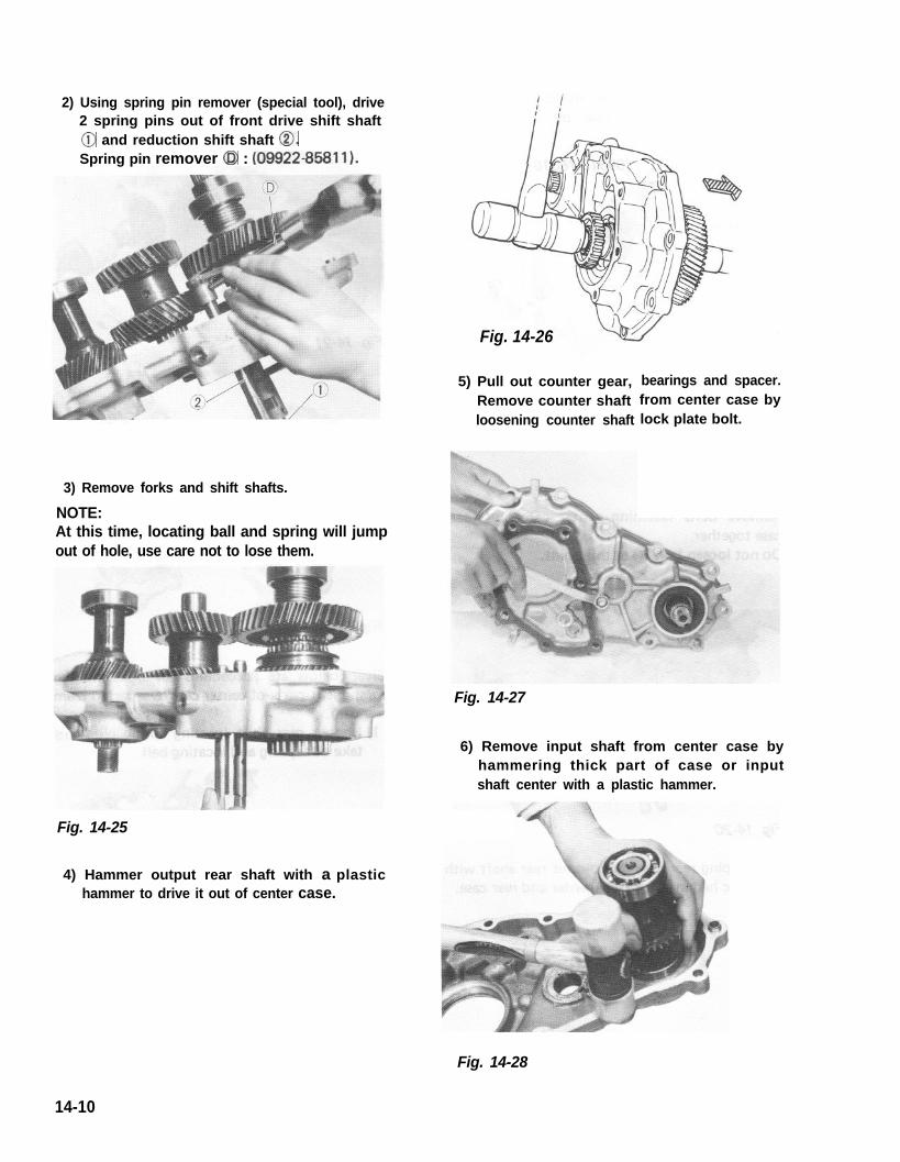
2) Using spring pin remover (special tool), drive2 spring pins out of front drive shift shaft@ and reduction shift shaft 0.Spring pin remover @ : (09922-85811).
Fig. 14-24
3) Remove forks and shift shafts.
NOTE:At this time, locating ball and spring will jumpout of hole, use care not to lose them.
Fig. 14-25
4) Hammer output rear shaft with a plastichammer to drive it out of center case.
5) Pull out counter gear,Remove counter shaftloosening counter shaft
bearings and spacer.from center case bylock plate bolt.
Fig. 14-27
6) Remove input shaft from center case byhammering thick part of case or inputshaft center with a plastic hammer.
Fig. 14-28
14-10
Fig. 14-26

7) Remove output shaft rear bearing andretainer together by using bearing puller.After removing bearing, speedometer drivegear, thrust washer, output low gear andneedle roller bearing can be removed.
Fig. 14-29
8) Remove front drive clutch hub circlip andpull clutch hub off shaft by using bearingpuller and puller attachment (special tool A).
NOTE:Use care to prevent damage to needle rollerbearing in output rear shaft when removingclutch hub.
/(A) 0 9 9 2 6 3 8 0 1 0
Fig. 14-30
9) Remove front bearing by using bearingpuller and puller attachment (special toolA).
NOTE:Use care to prevent damage to needle rollerbearing in output rear shaft while bearing isbeing removed.
(A) 0 9 9 2 6 - 5 8 0 1 0
Fig. 14-31
10) When input shaft is removed or center caseand rear case are separated, input shaftbearings may come off. In such a case,bearings can be removed from shaft by usingbearing puller.
**ita
“+
Fig. 14-32
14-11
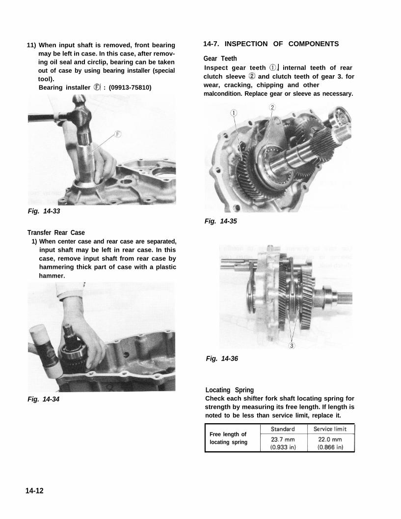
11) When input shaft is removed, front bearingmay be left in case. In this case, after remov-ing oil seal and circlip, bearing can be takenout of case by using bearing installer (specialtool).Bearing installer @ : (09913-75810)
Fig. 14-33
Transfer Rear Case1) When center case and rear case are separated,
input shaft may be left in rear case. In thiscase, remove input shaft from rear case byhammering thick part of case with a plastichammer.
Fig. 14-34
14-7. INSPECTION OF COMPONENTS
Gear TeethInspect gear teeth 0, internal teeth of rearclutch sleeve @ and clutch teeth of gear 3. forwear, cracking, chipping and other malcondition. Replace gear or sleeve as necessary.
Fig. 14-35
Fig. 14-36
Locating SpringCheck each shifter fork shaft locating spring forstrength by measuring its free length. If length isnoted to be less than service limit, replace it.
Free length oflocating spring
14-12

Fig. 14-37
BearingsCheck each bearing by spinning its outer race byhand to “feel” smoothness of rotation. Replacebearing if noted to exhibit sticking, resistanceor abnormal noise when spun or rotated byhand.
Fig. 14-38
Side Clearance of GearsWith gear, bearing and thrust washer installedon shaft, check for side clearances of gears.If clearance exceeds service limit, replace thrustwasher.
I Side clearanceof gear Standard Service limit I
output low gear 0 .175 - 0.325mm 0.7mmgears high gear (0 .007 - 0.012in) (0.027in)
Fig. 14-40 Output low gear
Gear Shift ShaftsCheck each part as indicated in below figures foruneven wear. Replace defective parts.
Fig. 14-41
14-13
Fig. 14-39 Output high gear

4WD Gear Shift LeverCheck lower end of gear shift lever where gearshift fork shaft contacts @ for wear and anykind of damage. Worn or damaged shift levermust be replaced with new one.
14-8. REASSEMBLY
NOTE:l All parts to be used in reassembly must be
perfectly clean.l Oil or grease sliding and rubbing surfaces of
transfer components just before using themin reassembly with gear oil and SUZUKISUPER GREASE A (99000-25010).
l Oil seals, “0” rings, gaskets and similar sealingmembers must be in perfect condition. Forthese members, use replacement parts instock.
l Tightening torque is specified for importantfasteners - mainly bolts - of transfer andother components. Use torque wrenches andconstantly refer to specified data given inP. 14-23.
Fig. 14-42
Input ShaftPress-fit bearings onto both sides of input shaftby using bearing installer (special tool).Bearing installer (A) : (09913-84510)
(A)
Fig. 14-43
14-14

Output Rear ShaftInstall following parts onto shaft in such orderand directions as prescribed in the figure.
6 9
1. Circlip2. Hub3. Bearing4. Bearing outer ring5. Thrust washer6. Output high gear7. Bearing (long)
8. Output rear shaft
9. Sleeve10. Bearing (short) 11. Outputlowgaar12. Thrust washer13. Speed meter drive gear14. Bearing15. Retainer
Fig. 14-44
1) After installing bearing (long), high gear andthrust washer, press-fit bearing 1. and thenhub @ by using bearing installer (specialtool).
Bearing installer (A) : (0991384510)
Fig. 14-45
2) Fit circlip @ securely into groove in shaft.
Fig. 14-46
3) After installing sleeve, bearing (short), lowgear and thrust washer, press-fit speedometerdrive gear by using bearing installer (specialtool).Bearing installer (A) : (09913-84510)
(A)
Fig. 14-47
4) Press-fit bearing @ and the retainer @ byusing bearing installer (special tool).Bearing installer (A) : (0991384510)
Fig. 14-48 14-15

Shim Adjustment of Input and Output ShaftsClearance in thrust direction of both input andoutput shafts is adjusted by putting shimsbetween input shaft rear bearing and rear casefor input shaft and between output shaft rearbearing and rear case for output shaft.As thrust clearance is specified as followsdetermine shim thickness to meet specification according to the following procedures.
Thrust clearance 0.05 - 0.15 mmspecification (0.002 - 0.006 in.)
[Input shaft]1) Take measurement “A” of rear case as shown
in figure below by using depth gauge,2) Take measurement “6” of center case with
bearing circlip installed.3) Take measurement “C” (between bearing
inner races) of input shaft with bearingsinstalled, by using micrometer.
NOTE:l Before measuring, make sure that each bearing
is free from abnormal noise or resistance byspinning its outer race.
l Each measurement in above steps 1) to 3)must be taken accurately in careful manner,If shim thickness is determined based onrough measurement, clearance of each shaft inthrust direction will not satisfy specification.And improper clearance may cause oil leakage,broken bearing and abnormal noise.
l Take the same measurement at 3 to 4 diffe-rent positions and use their mean.
6
1.1. Center caseCenter case 5.5. Bearing circlipBearing circlip2.2. Rear caseRear case 6.6. GasketGasket3.3. Input shaftInput shaft 7.7. Gasket thicknessGasket thickness4. Output shaft4. Output shaft (0.3 mm or 0.012 in)(0.3 mm or 0.012 in)
Fig.Fig. 14-48-14-48- 11
4) Using measurements obtained in steps 1) to 3)and equation described below, calculate shimthickness which is necessary for properthrust clearance.Thrust clearance = (“A” + “B” + Gasketthickness) - “C”As the above equation holds for thrustclearance and gasket thickness is specified as0.3 mm and thrust clearance as 0.05 to 0.15mm, shim thickness is calculated by thefollowing equation.Shim thickness = (“A” + “B” + 0.3 ) -(“C” + 0.05 - 0.15)
[Example]Supposing A, B and C are as follows;A = 81.35 mm (3.203 in.)B = 35.70 mm (1.405 in.)C = 117.05 mm (4.608 in.)Shim thickness = (81.35 + 35.70 + 0.3) -
(117.05 + 0.05 N 0.15)= 117.35- 117.10~ 117.20= 0.25 - 0.15
In this case, use of 0.15 to 0.25 mm (0.006 to0.009 in) thick shim(s) will ensure specifiedthrust clearance which is 0.05 to 0.15 mm(0.002 to 0.006 in). Therefore 2 pieces of0.1 mm (0.004 in) thick shim should beselected in available shims below to satisfythickness.
14-16
Fig. 14-48-1

5) When shim thickness is determined, selectproper shim(s) from among the followingshims and use it (them) between input shaftrear bearing and rear case when matchingcenter case and rear case.
Available shim 0.1, 0.3,0.5 mmsize (thickness) (0.004,0.012,0.020 in.) I
[Output shaft]Just as with input shaft, take measurements of“ A ’ “, “B’ ” and “C’ ” a s i n d i c a t e d i n F i g .14-48-1, calculate shim thickness and installproper shim(s) between output shaft rear bearingand rear case when matching center case andrear case.
1. Shim for input shaft2. Shim for output shaft
fig. 14-48-2
14-17
Fig. 14-48-2

Rear Case1) Install oil seal in rear case and apply grease
to oil seal lip.
Center Case1) Install input shaft front bearing circlip and
oil seal in center case.Snap ring pliers @ : (09900~6108)
Fig. 14-49Fig. 14-51
2) Install counter shaft thrust washer to rearcase, bringing its face without depressionsagainst case and fit its bent portion securelyinto groove in case.
NOTE:Apply ample amount of grease to both surfacesof washer so as to lubricate sliding surfaces andprevent washer from moving out of place orslipping off.
Fig. 14-50
2) Install input shaft to center case.
Fig. 14-52
3) After greasing 0 ring on counter shaft,insert shaft into center case and secureshaft with lock plate and bolt.
Fig. 14-53
Fig. 14-50
14-18Fig. 14-53
Fig. 14-52

4) Install the counter shaft thrust washer tocenter case. For installation, apply ampleamount of grease to both faces of the washerso as to lubricate sliding surfaces and preventit from moving out of place or slipping offand bring its face without depressions againstcenter case, and fit its bent portion intogroove in case securely.
Fig. 14-54
5) Install needle roller bearings, spacer andcounter gear on counter shaft.
Fig. 14-55
6) Install output shaft assembly to center case.
Fig. 14-56
7) When installing front drive shift shaft andreduction shift shaft in center case, installspring 0, ball 0, shaft 0, ball @, shaft0, ball 8, spring 0 and plug 8. in thatorder.
d 18-3ON.m
Fig. 14-57(1.8 - 3.0 kg-m 1(13.5 - 21.5 lb-ft)
8) Fit forks on shift shafts and lock themwith spring pins. Forks should be fitted incorrect direction according to below figure.
Fig. 14-58
14-19
Fig. 14-54
Fig. 14-55
Fig. 14-58
Fig. 14-57
Fig. 14-56
14-19

Center and Rear Cases1) Check center case (or rear case) to ensure
that it is provided with 2 dowel pins 0.
Fig. 14-59
2) Put gasket on center case. Bring rear caseand center case into match and applyuniform force gradually all around rear casewith a plastic hammer. Tighten center casesecuring bolts to specified torque.
NOTE:l Matching must be made carefully so as not to
move countershaft thrust washers out of place.l Be sure to install shims determined in previ-
ous item “Shim Adjustment of Input andOutput Shafts” between input shaft rearbearing and rear case and between outputshaft rear bearing and rear case.
Fig. 14-61
Fig. 14-62
3) Apply grease to output front shaft rearbearing.
Fig. 14-60Fig. 14-63
14-20

Front Case 1) Install bearing, circlip and oil seal to front
case. Apply grease to oil seal lip and installoutput front shaft using bearing installer(special tool).Bearing installer (A) : (09913-76010)
Fig. 14-64
2) Put gasket on center case.3) Check front case to ensure that it is provided
with 2 dowel pins.
Fig. 14-65
4) Install front case to center case.
Fig. 14-66
5) When installing speedometer driven gearand its gear case in rear case, apply grease to0 ring and oil seal lip, and align bolt holesin rear case and driven gear case.
Fig. 14-67
6) Install 4WD ball and switch. Then clampswitch lead wire properly.
/ 1.6 - 2.3 kgmFig. 14-68 (12.0 - 16.5 lb-h)
14-21

7) Install propeller shaft flanges and tightennuts to specified torque and talk the nuts.
8) Upon completion of entire assembly work,install transfer in chassis body in reversesequence of removal. Pour gear oil intotransfer gear box.Refer to information given in next oil andoil capacity for oil to be used and specifiedamount.
NOTE:When installing oil filler and drain plugs totransfer case, apply sealant (SUZUKI BONDNo.1215, 99000-31110) to thread part of plug.
14-9. MAINTENANCE SERVICES
Oil LevelOil level must be checked with car held inhorizontal position in both front to rear and sideto side directions.Oil level plug and oil filler plug are one and thesame as shown in figure.If oil flows out of filler plug hole or if oil level isfound up to hole when plug is removed, amountof oil is appropriate. Replenish oil if noted asinsufficient.
Oil and Oil CapacityWhenever car is lifted up for any service includ-ing oil change, make sure to check aroundtransfer gear box for oil leakage. Correct defects,if any, and change or refill oil.
Transfer oil capacity 0.8 litre (1.7/l .4 US/Imp. pt)
Transfer oil Gear oil SAE 8OW-90,specification 75W-80 or 75W-90
It is highly recommended to use SAE 75W-90gear oil.For viscosity chart, refer to P. 1-20.
@ : Oil drain plug
Fig. 14-70 @ : Oil filler & level plug
14-22

14-10. TIGHTENING TORQUE
Counter shaft lock
Universal joint flange
Oil filler and drain plug
Cross joint bolt & nut
Transfer mounting nut
Transfer mountingbracket bolt
Universal jointflange nut
Counter shaft lockplate bolt
Center case bolt
Front case bolt
Fastening parts
14-23