To Our Friends and Customers
189
1 HITACHI AIC CAPACITORS HITACHI AIC / BOSTON AIC • 69 Milk Street • Westborough, MA 01581 • Phone: 508-366-4092 • Fax: 508-366-9164 To Our Friends and Customers As one of the leading capacitor manufacturers in the world, Hitachi AIC offers an excellent variety of capacitors to serve your design needs. In this catalog, along with an expanded product offering, we have included technical specifications, product descriptions, and performance characteristics with charts, graphs, and application guidelines to aid in choosing the right capacitor. Our Aluminum Electrolytic Capacitors consist of a complete range of Screw Terminal models with voltage ratings to 550 volts DC. The Snap-Mount capacitors offer extended life versions of 3000 hours and 5000 hours, and several with over voltage shut-off features. We also offer PhotoFlash capacitors in 330 volts DC and 360 volts DC, with capacitance values to 1500 microfarads. Hitachi AIC has three foil processing facilities to ensure a constant supply of hard to get high voltage aluminum foil. The Film Capacitor section shows several series. Surface-Mount, leaded and wrapped axial capacitors have voltage ratings to 630 volts DC. Quality has always been a priority with the Hitachi family of products. The capacitors manufactured by Hitachi AIC maintain the same high level of standards synonymous with the Hitachi name. Hitachi AIC has also expanded the Customer Service and Engineering departments at our main office in Boston, with the addition of a sales office in Chicago and a network of reps nationwide to provide you with expedient answers to your questions. We at Hitachi welcome the opportunity to assist you in your capacitor design requirements. It is our pleasure to serve you. AIC
Transcript of To Our Friends and Customers
1
HITACHI AIC CAPACITORS
HITACHI AIC / BOSTON AIC • 69 Milk Street • Westborough, MA 01581 • Phone: 508-366-4092 • Fax: 508-366-9164
To Our Friends and Customers
As one of the leading capacitor manufacturers in the world, Hitachi AIC offersan excellent variety of capacitors to serve your design needs.
In this catalog, along with an expanded product offering, we have includedtechnical specifications, product descriptions, and performance characteristicswith charts, graphs, and application guidelines to aid in choosing the rightcapacitor.
Our Aluminum Electrolytic Capacitors consist of a complete range of ScrewTerminal models with voltage ratings to 550 volts DC. The Snap-Mount capacitorsoffer extended life versions of 3000 hours and 5000 hours, and several withover voltage shut-off features. We also offer PhotoFlash capacitors in330 volts DC and 360 volts DC, with capacitance values to 1500 microfarads.Hitachi AIC has three foil processing facilities to ensure a constant supply ofhard to get high voltage aluminum foil.
The Film Capacitor section shows several series. Surface-Mount, leaded andwrapped axial capacitors have voltage ratings to 630 volts DC.
Quality has always been a priority with the Hitachi family of products. Thecapacitors manufactured by Hitachi AIC maintain the same high level ofstandards synonymous with the Hitachi name.
Hitachi AIC has also expanded the Customer Service and Engineeringdepartments at our main office in Boston, with the addition of a sales office inChicago and a network of reps nationwide to provide you with expedientanswers to your questions.
We at Hitachi welcome the opportunity to assist you in your capacitordesign requirements.
It is our pleasure to serve you.
AIC

2
HITACHI AIC CAPACITORS
AICHITACHI AIC / BOSTON AIC • 69 Milk Street • Westborough, MA 01581 • Phone: 508-366-4092 • Fax: 508-366-9164
©2000 Hitachi AIC. All rights reserved.
Specification in this catalog are subject to change without notice in orderfor Hitachi AIC to bring the latest product information to its customers.
ISO 9001JCQA-0152
QS AccreditationJAB R003
ISO
CERTIFIED
14001ISO
9001CERTIFIED
3
HITACHI AIC CAPACITORS
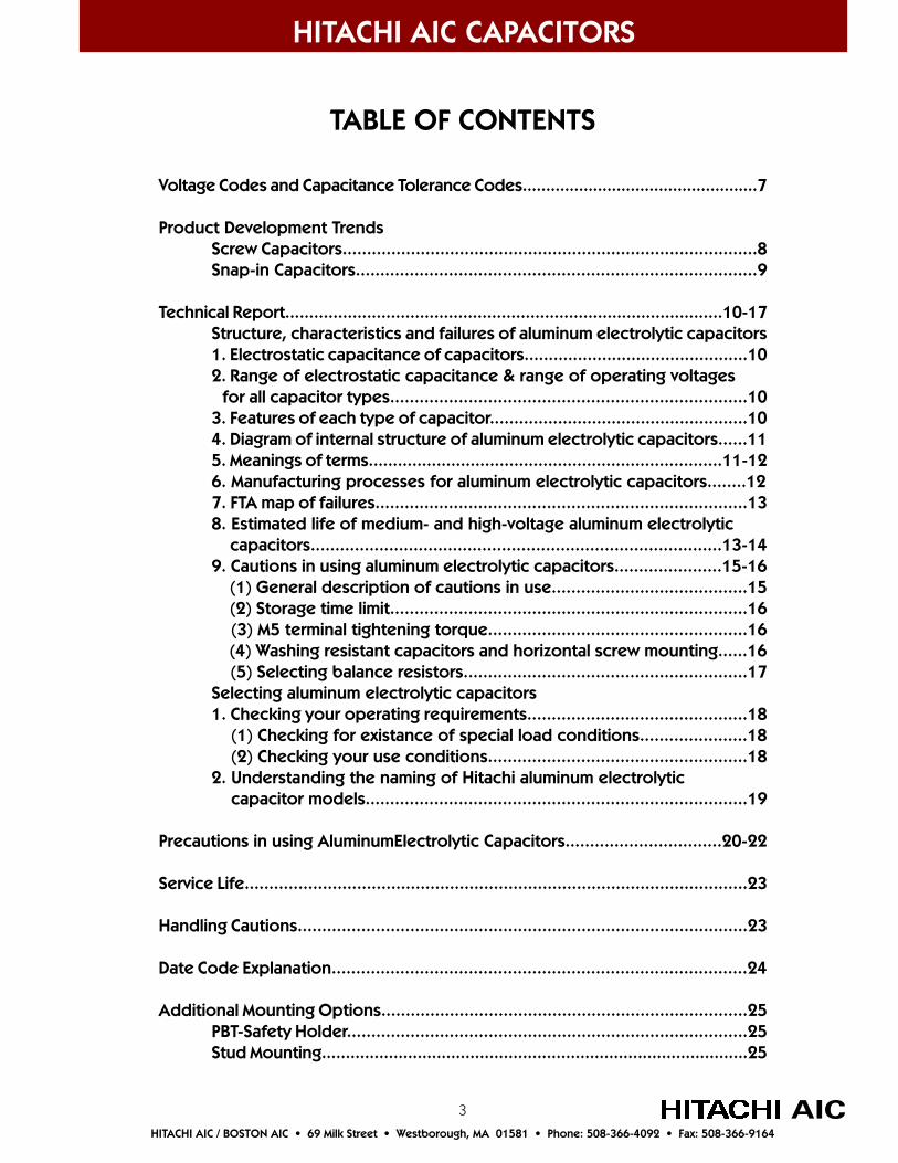
TABLE OF CONTENTS
Voltage Codes and Capacitance Tolerance Codes..................................................7
Product Development TrendsScrew Capacitors.....................................................................................8Snap-in Capacitors..................................................................................9
Technical Report...........................................................................................10-17Structure, characteristics and failures of aluminum electrolytic capacitors1. Electrostatic capacitance of capacitors..............................................102. Range of electrostatic capacitance & range of operating voltages
for all capacitor types.........................................................................103. Features of each type of capacitor.....................................................104. Diagram of internal structure of aluminum electrolytic capacitors......115. Meanings of terms.........................................................................11-126. Manufacturing processes for aluminum electrolytic capacitors........127. FTA map of failures............................................................................138. Estimated life of medium- and high-voltage aluminum electrolytic capacitors....................................................................................13-149. Cautions in using aluminum electrolytic capacitors......................15-16 (1) General description of cautions in use........................................15 (2) Storage time limit.........................................................................16 (3) M5 terminal tightening torque.....................................................16 (4) Washing resistant capacitors and horizontal screw mounting......16 (5) Selecting balance resistors..........................................................17Selecting aluminum electrolytic capacitors1. Checking your operating requirements.............................................18 (1) Checking for existance of special load conditions......................18 (2) Checking your use conditions.....................................................182. Understanding the naming of Hitachi aluminum electrolytic capacitor models..............................................................................19
Precautions in using AluminumElectrolytic Capacitors................................20-22
Service Life.......................................................................................................23
Handling Cautions............................................................................................23
Date Code Explanation.....................................................................................24
Additional Mounting Options...........................................................................25PBT-Safety Holder..................................................................................25Stud Mounting.........................................................................................25
AICHITACHI AIC / BOSTON AIC • 69 Milk Street • Westborough, MA 01581 • Phone: 508-366-4092 • Fax: 508-366-9164
4AICHITACHI AIC / BOSTON AIC • 69 Milk Street • Westborough, MA 01581 • Phone: 508-366-4092 • Fax: 508-366-9164
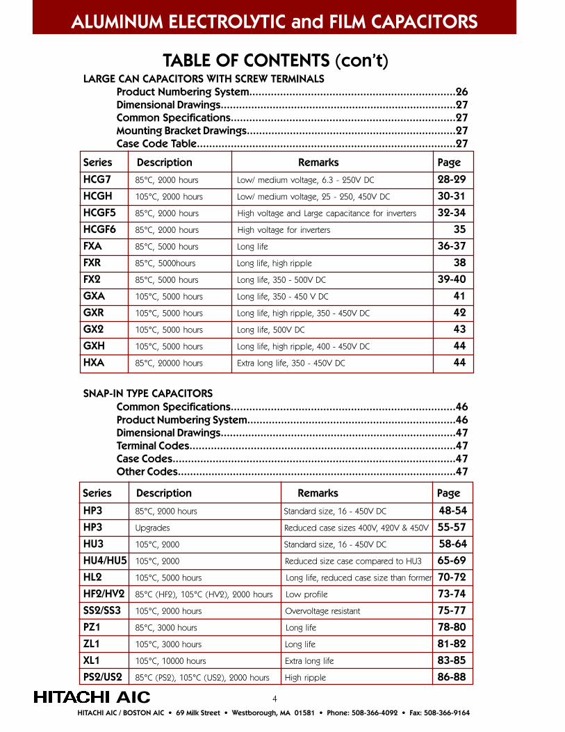
TABLE OF CONTENTS (con’t)LARGE CAN CAPACITORS WITH SCREW TERMINALS
Product Numbering System...................................................................26Dimensional Drawings.............................................................................27Common Specifications.........................................................................27Mounting Bracket Drawings....................................................................27Case Code Table....................................................................................27
HCG7 85°C, 2000 hours Low/ medium voltage, 6.3 - 250V DC 28-29
HCGH 105°C, 2000 hours Low/ medium voltage, 25 - 250, 450V DC 30-31
HCGF5 85°C, 2000 hours High voltage and Large capacitance for inverters 32-34
HCGF6 85°C, 2000 hours High voltage for inverters 35
FXA 85°C, 5000 hours Long life 36-37
FXR 85°C, 5000hours Long life, high ripple 38
FX2 85°C, 5000 hours Long life, 350 - 500V DC 39-40
GXA 105°C, 5000 hours Long life, 350 - 450 V DC 41
GXR 105°C, 5000 hours Long life, high ripple, 350 - 450V DC 42
GX2 105°C, 5000 hours Long life, 500V DC 43
GXH 105°C, 5000 hours Long life, high ripple, 400 - 450V DC 44
HXA 85°C, 20000 hours Extra long life, 350 - 450V DC 44
SNAP-IN TYPE CAPACITORSCommon Specifications.........................................................................46Product Numbering System....................................................................46Dimensional Drawings.............................................................................47Terminal Codes.......................................................................................47Case Codes............................................................................................47Other Codes...........................................................................................47
HP3 85°C, 2000 hours Standard size, 16 - 450V DC 48-54
HP3 Upgrades Reduced case sizes 400V, 420V & 450V 55-57
HU3 105°C, 2000 Standard size, 16 - 450V DC 58-64
HU4/HU5 105°C, 2000 Reduced size case compared to HU3 65-69
HL2 105°C, 5000 hours Long life, reduced case size than former 70-72
HF2/HV2 85°C (HF2), 105°C (HV2), 2000 hours Low profile 73-74
SS2/SS3 105°C, 2000 hours Overvoltage resistant 75-77
PZ1 85°C, 3000 hours Long life 78-80
ZL1 105°C, 3000 hours Long life 81-82
XL1 105°C, 10000 hours Extra long life 83-85
PS2/US2 85°C (PS2), 105°C (US2), 2000 hours High ripple 86-88
ALUMINUM ELECTROLYTIC and FILM CAPACITORS
Series Description Remarks Page
Series Description Remarks Page
5 AICHITACHI AIC / BOSTON AIC • 69 Milk Street • Westborough, MA 01581 • Phone: 508-366-4092 • Fax: 508-366-9164
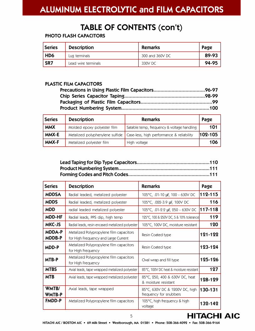
TABLE OF CONTENTS (con’t)PHOTO FLASH CAPACITORS
PLASTIC FILM CAPACITORSPrecautions in Using Plastic Film Capacitors.....................................96-97Chip Series Capacitor Taping..........................................................98-99Packaging of Plastic Film Capacitors...................................................99Product Numbering System...............................................................100
MMX Molded epoxy polyester film Satable temp, frequency & voltage handling 101
MMX-E Metalized polyphenylene sulfide Case-less, high performance & reliability 102-105
MMX-F Metalized polyester film High voltage 106
Lead Taping for Dip Type Capacitors.....................................................110Product Numbering System...................................................................111Forming Codes and Pitch Codes...........................................................111
MDDSA Radial leaded, metalized polyester 105°C, .01-10 µF, 100 - 630V DC 112-115
MDDS Radial leaded, metalized polyester 105°C, .022-3.9 µF, 100V DC 116
MDD radial leaded metalized polyester 105°C, .01-2.2 µF, 250 - 630V DC 117-118
MDD-HF Radial leads, PPS dip, high temp 125°C, 100 & 250V DC, 5 & 10% tolerance 119
MKC-JS Radial leads, resin encased metalized polyester 105°C, 100V DC, moisture resistant 120
MDDA-P Metalized Polypropylene film capacitors
MDDB-P for High Frequency and Large Current
Metalized Polypropylene film capacitors
for High Frequency
Metalized Polypropylene film capacitors
for High Frequency
MTBS Axial leads, tape wrapped metalized polyester 85°C, 100V DC heat & moisture resistant 127
MTB Axial leads, tape wrapped metalized polyester 85°C, 250, 400 & 630V DC, heat& moisture resistant
WMTB/ Axial leads, tape wrapped
FMDD-P Metalized Polypropylene film capacitors 105°C, high frequency & highvoltage
Series Description Remarks Page
ALUMINUM ELECTROLYTIC and FILM CAPACITORS
HD6 Lug terminals 300 and 360V DC 89-93
SR7 Lead wire terminals 330V DC 94-95
Series Description Remarks Page
Series Description Remarks Page
Resin Coated type 121-122
Resin Coated type 123-124MDD-P
MTB-P Oval wrap and fill type 125-126
130-13185°C, 630V DC & 1200V DC, highfrequency for snubbers
128-129
WMTB-P
132-142

6AICHITACHI AIC / BOSTON AIC • 69 Milk Street • Westborough, MA 01581 • Phone: 508-366-4092 • Fax: 508-366-9164
FILM and TANTALUM CAPACITORS
English/Metric Conversion Chart...............................................Inside Back Cover
TABLE OF CONTENTS (con’t)PLASTIC FILM CAPACITORS (continued)
Capacitors for Noise Prevention.............................................................143
MKC-UF Noise Prevention, High Voltage, UL Resin Cased, 85°C 144
MKC-PV Noise Prevention, Metalized Polypropylene Resin Cased, 85°C 145
NEL Noise Prevention with Protective Mechanism Small Size, 85°C 145
TANTALUM CAPACITORSPrecautions in Using Tantalum Capacitors........................................146-150About Downsizing (upgrading)................................................................150Tape and Reel Packaging..........................................................................151Specifications Table..........................................................................152-153Section Contents and Product Numbering System.................................154
TMCS Chip, 4 to 50V DC, .1 to 68 µF Standard size, excellent frequencyand impedance characteristics
TMCM Chip, 2.5 to 50V DC, .15 to 470 µF Reduced size compared to TMCS 158-166
TMCP Chip, 2.5 to 25V DC, 0.47 to 22 µF 0805 size, for AV applications 167-169
TMCU Chip, 2.5 to 35V DC, .1 to 220 µF Low profile 170-176
TMCR Chip, 6.3 to 35V DC, 10 to 330 µF Low ESR, high frequency and highspeed applications
TMCH Chip, 4 to 50V DC, . 1 to 100 µF High reliability, high temperature,suitable for automotive applications
TMCTX Chip, 20 to 59V DC, 1.0 to 68 µF Internal fuse for protection againstover-voltage
TMCN Chip Polymer, 4 to 10V DC, 10 to 47 µF High performance, Low ESR 188-189
Series Description Remarks Page
Series Description Remarks Page
155-157
177-179
180-183
184-187
7 AICHITACHI AIC / BOSTON AIC • 69 Milk Street • Westborough, MA 01581 • Phone: 508-366-4092 • Fax: 508-366-9164
HITACHI AIC CAPACITORS
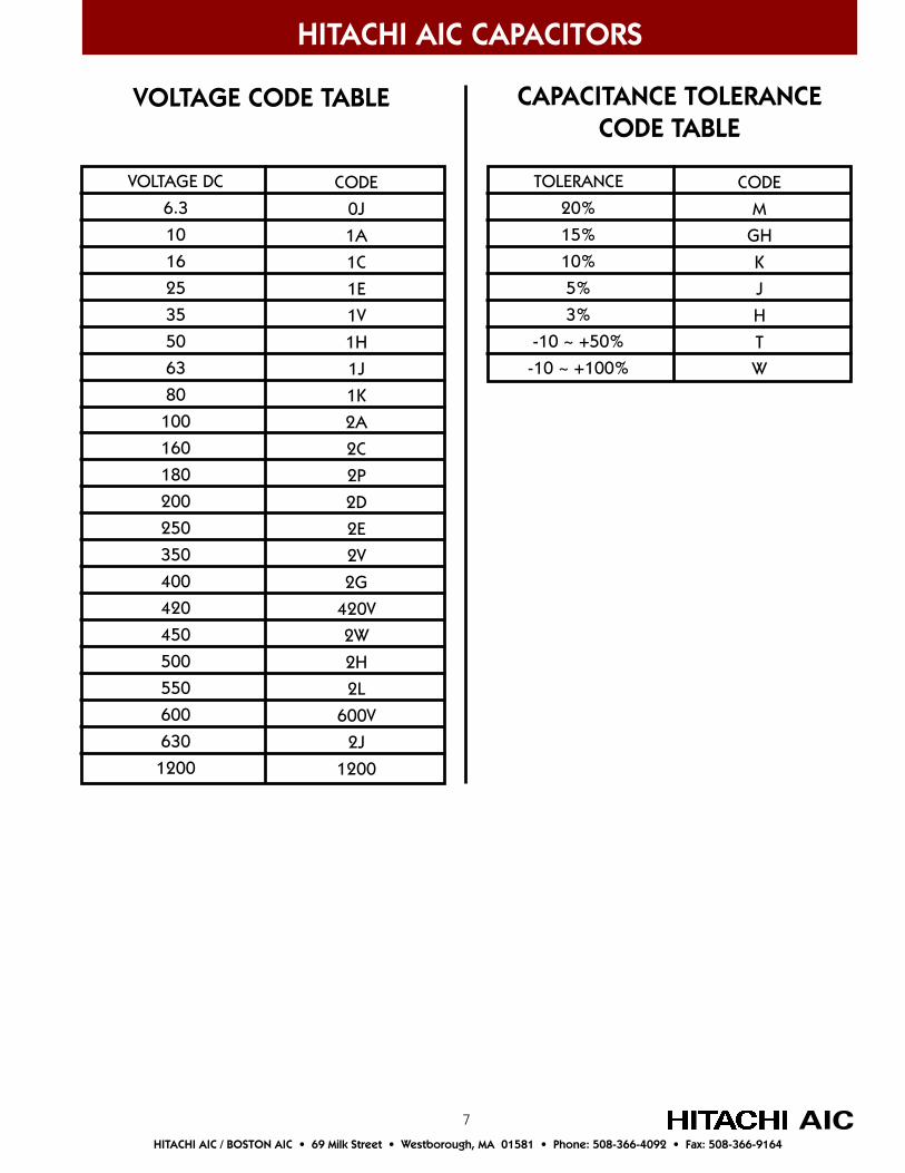
VOLTAGE CODE TABLE CAPACITANCE TOLERANCECODE TABLE
TOLERANCE
20%
15%
10%
5%
3%
-10 ~ +50%
-10 ~ +100%
CODE
M
GH
K
J
H
T
W
VOLTAGE DC
6.3
10
16
25
35
50
63
80
100
160
180
200
250
350
400
420
450
500
550
600
630
1200
CODE
0J
1A
1C
1E
1V
1H
1J
1K
2A
2C
2P
2D
2E
2V
2G
420V
2W
2H
2L
600V
2J
1200
8
ALUMINUM ELECTROLYTIC CAPACITORS
AICHITACHI AIC / BOSTON AIC • 69 Milk Street • Westborough, MA 01581 • Phone: 508-366-4092 • Fax: 508-366-9164
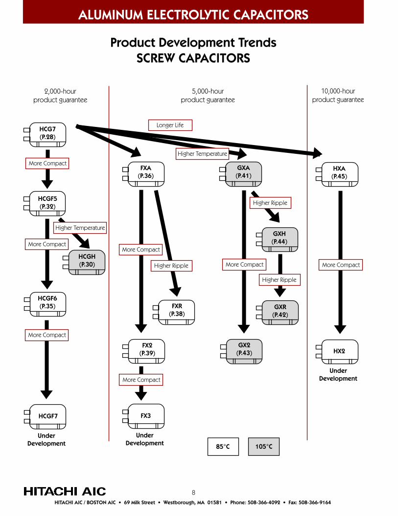
Product Development TrendsSCREW CAPACITORS
10,000-hourproduct guarantee
More Compact
UnderDevelopment
HXA(P.45)
HX2
2,000-hourproduct guarantee
More Compact
UnderDevelopment
HCGH(P.30)
HCGF6(P.35)
HCGF7
5,000-hourproduct guarantee
More Compact
More Compact
Higher Ripple
UnderDevelopment
FXA(P.36)
FXR(P.38)
FX2(P.39)
FX3
More Compact
Higher Ripple
Higher Ripple
GXA(P.41)
GXH(P.44)
GXR(P.42)
GX2(P.43)
Longer Life
Higher Temperature
HCGF5(P.32)
HCG7(P.28)
More Compact
More Compact
Higher Temperature
85°C 105°C
9
ALUMINUM ELECTROLYTIC CAPACITORS
AICHITACHI AIC / BOSTON AIC • 69 Milk Street • Westborough, MA 01581 • Phone: 508-366-4092 • Fax: 508-366-9164
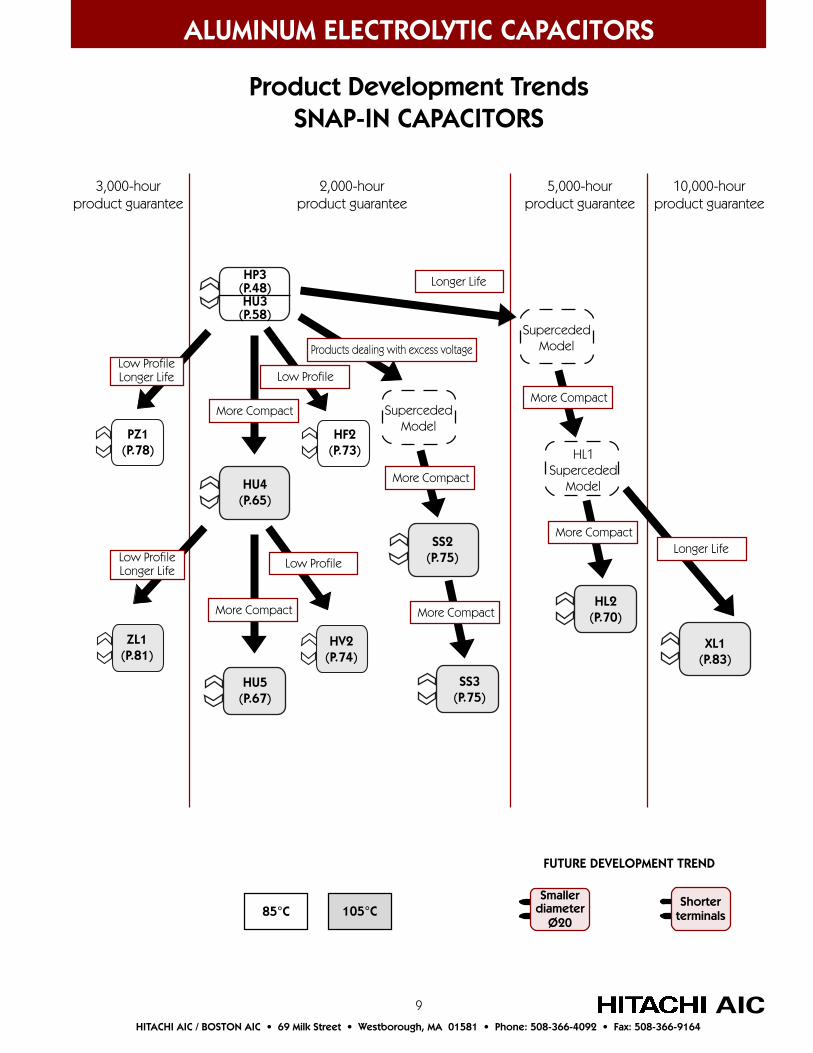
Product Development TrendsSNAP-IN CAPACITORS
10,000-hourproduct guarantee
5,000-hourproduct guarantee
2,000-hourproduct guarantee
3,000-hourproduct guarantee
Longer Life
FUTURE DEVELOPMENT TREND
Smallerdiameter
Ø20
Shorterterminals
More Compact
More Compact
HP3(P.48)HU3
(P.58)
HU4(P.65)
HU5(P.67)
Longer Life
XL1(P.83)
Products dealing with excess voltage
PZ1(P.78)
ZL1(P.81)
Low ProfileLonger Life
Low ProfileLonger Life
HF2(P.73)
SupercededModel
More Compact
More Compact
SS2(P.75)
SS3(P.75)
HV2(P.74)
Low Profile
Low Profile
SupercededModel
More Compact
More Compact
HL2(P.70)
85°C 105°C
HL1Superceded
Model

10
ALUMINUM ELECTROLYTIC CAPACITORS
AICHITACHI AIC / BOSTON AIC • 69 Milk Street • Westborough, MA 01581 • Phone: 508-366-4092 • Fax: 508-366-9164
TECHNICAL REPORTStructure, characteristics and failures
1. Electrostatic capacitance of capacitors
Capacitors have a structure like that shown in Figure 1, in which adielectric substrate is sandwiched between two electrodes. Theelectrostatic capacitance (C) is:
εr :Proportional dielectric constantε0 :Dielectric constant in a vacuum (8.85 x 10⁻¹² F/m)d :Distance between electrodes (m)S :Electrode area (m2)
Figure 1. Basic Capacitor Structure
2. Range of electrostatic capacitance and operating voltages for all capacitor types
Aluminum Electrolytic
Aluminum Electrolytic
Tantalum Electrolytic
Tantalum Electrolytic
Multilayer Ceramic
Multilayer Ceramic
Film
Film
Electrostatic Capacitance
Operating Voltage VDC
1 10 100 1000
pF µF F1 10 100 1K 10K 100K 1 10 100 1K 10K 100K 1
3. Features of each type of capacitor
Aluminum Tantalum Ceramic Film
Dielectric
ProportionalDielectric Constant
PackageStyle
Advantages
Disadvantages
Aluminum Oxide(Al 2O3)
8 ~ 10
Screw terminal, Snap-interminal, Lead terminal, Chip
•Low price •Compact with large capacitance
•Short life at high temps •Large capacitance tolerance •Polarity (main type)
Tantalum Tetroxide(Ta
2O
5)
27
Chip (main type), dip
•Compact with compara- tively high electrolytic capacitance •Semi-permanent life
•Operation requires study of voltage derating •Polarity
Titanium Oxide Bariumtypes, etc
1500 ~ 15000(Titanium Oxide Barium)
Chip (main type), dip
•Compact (especially multilayer types) •No polarity
•Large changes in electrolytic capacitance caused by temperature and DC voltage
Polyester,Polypropylene, etc.
2.1 ~ 3.1
Chip dip (main type),Chip and case
•Good Characteristics •Can manufacture all voltages—low to high •High reliability
•Large outside dimensions
Dielectric substrate
Electrodes
+ –S
C=ε—Sd
e=εr ε0

11
(1) Working Voltage (W.V.) and Surge Voltage (SV). W.V. is the voltage that can be constantly applied, while SV is the maximum voltage that can be withstood for a short period of time (30 seconds according to JIS C5141).
(2) Permissible tolerance in electrostatic capacitance. The allowable range of dispersion in electrostatic capacitance. Aluminum corrodes the electrodes (etches), which increases the amount of surface area and causes the dispersions.
(3) Equivalent Series Resistance. The Equivalent Series Resistance puts together electrical resistance of negative and positive foils, electrolytic fluid resistance, and contact resistance of each connecting section.
(4) Tangent of loss angle (generally called Tan delta (tan δ)). When current is placed on an ideal insulator, the current moves ahead 90 degrees in phase from the voltage. However, because some loss occurs in the general insulator, the forward angle of phase is 90°- δ). The δ is called dielectric loss. Tan δ is obtained by the following formula.
tan X = ω CR [ ω = 2 π f (f = frequency [Hz], C = electrolytic capacitance [F] and R = Equivalent SeriesResistance [ Ω ].]
(5) Impedance Z (Ω). Resistance in an AC circuit Z = √ R2+(ωL–1/ωC)2
[R: Equivalent Series Resistance (Ω), C: electrolytic capacitance (F), L: inductance (H), ω = 2 π f (f = frequency [Hz] )].
(6) Leakage current. DC current will not flow in a capacitor after it has been completely charged with DC current. However, dielectric resistance is not infiinite and a micro-current will flow through the capacitor. Electrolytic capacitors can be damaged during processing by an oxide film and when it is recovered the micro-current will flow.
ALUMINUM ELECTROLYTIC CAPACITORS
AICHITACHI AIC / BOSTON AIC • 69 Milk Street • Westborough, MA 01581 • Phone: 508-366-4092 • Fax: 508-366-9164
5. Meanings of Terms
4. Diagram of internal structure of aluminum electrolytic capacitors
Parts Name
Terminal
Case
Exterior material
Insulation cap
Rubber ring
Safety vent
Leads
Fixing compound
Element
Material
Aluminum
Aluminum
PVC
PPS phenol
EPT
Silicone rubber
Aluminum
—
See Fig. 3
No.
1
2
3
4
5
6
7
8
9
Fig. 2 - Diagram of Internal Structure Fig. 3 - Diagram of Device and Basic Structure
Anode FoilElectrolytic paper + liquid
Element
Leads
CathodeFoil
Anode foil (about 100µm
Dielectric(aluminum oxide = Al2O3)
Electrolyte liquid(main medium: ethylene glycol)
Anode foil (15-50µm)
Rated Voltage (V) 6.3 10 16 25 35 50 63 80 100 160 200 250 315 350 400 450 500Rated Surge Voltage (SV) 8 13 20 32 44 63 79 100 125 200 250 300 365 400 450 500 550

12
ALUMINUM ELECTROLYTIC CAPACITORS
AICHITACHI AIC / BOSTON AIC • 69 Milk Street • Westborough, MA 01581 • Phone: 508-366-4092 • Fax: 508-366-9164
(1) Etching (expanding surface area) The processing for expanding the surface of aluminum foil. High purity aluminum foil, 500mm wide and 0.1mm thick is continuously processed electrochemically by flowing direct current through a chlorine bath solution. The surface area is expanded 50-100 times for low-voltage use capacitors and 10-40 times for medium to high-voltage use capacitors.
(2) Forming (dielectric formation) The process of forming the dielectric (Al 2O3). The dielectric is formed in a continuous electrochemical process by passing a voltage that is 120-200 percent of the working voltage through etched aluminum foil that is in a bath of boric acid ammonium. The dielectric is extremely thin, about 14Å/V.
(3) Slitting The formed aluminum foil (positive electrode foil), negative electrode foil and electrolytic paper are slit according to the product size.
(4) Winding Capacitors contain a positive (Anode) foil and a negative (Cathode) foil. These are separated by electrolytic paper
and wound into a cylinder. The separator paper prevents the two foils from contacting each other and shorting.This “sandwich” of separator paper and foil is wrapped around the lead wires and tabs to form the capacitor element.
(5) Impregnation The process of inserting the electrolytic liquid into the wound assembly by pressurization and depressurization. The electrolytic fliud uses such things for solvents as boric acid and organic acid ammonium with ethylene glycol as a main medium. These have a very big effect on the life, frequency characteristics, range of operating temperature and temperature characteristics of the capacitor.
(6) Sealing The impregnated assembly is sealed in an aluminum can. Sealing material is used to keep it airtight.
(7) Reforming (aging) This is the process of applying voltage greater than the rated voltage of the capacitor at an elevated temperature to reform or repair dielectric that may have been damaged during assembly.
(8) Inspection of all parts Inspection is made of the external appearance and the electrical characteristics of all aged parts.
(9) Sampling, packaging and shipping An inspection is made according to fixed sampling standards and the capacitors that pass the inspection are packed and shipped. Detailed tests are made periodically to check quality.
Aluminum
Fig. 5 - Diagram of formation model
Aluminum oxide
6. Manufacturing processes for aluminum electrolytic capacitors
Fig. 4 - Diagram of etching model
Aluminum
(7) Ripple Current (IRMS) Ripple Current is the RMS value of the alternating current flowing through the capacitor, measured in Amps. If the ripple current applied is higher than the specified maximum permissible ripple current, the life of the capacitor becomes shorter. In extreme cases the capacitor will rupture.
13
ALUMINUM ELECTROLYTIC CAPACITORS
AICHITACHI AIC / BOSTON AIC • 69 Milk Street • Westborough, MA 01581 • Phone: 508-366-4092 • Fax: 508-366-9164
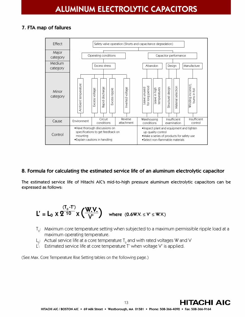
7. FTA map of failures
8. Formula for calculating the estimated service life of an aluminum electrolytic capacitor
The estimated service life of Hitachi AIC’s mid-to-high pressure aluminum electrolytic capacitors can beexpressed as follows:
L’ = L0 X 2 X ( ) where (0.6W.V. ≤ V’ ≤ W.V.)
T0: Maximum core temperature setting when subjected to a maximum permissible ripple load at a maximum operating temperature.L0: Actual service life at a core temperature T0 and with rated voltages W and VL’: Estimated service life at core temperature T’ when voltage V’ is applied.
(See Max. Core Temperature Rise Setting tables on the following page.)
Safety valve operation (Shorts and capacitance degradation)
Operating conditions Capacitor performance
Excess stress ManufactureDesignAbandon
Rap
id d
isch
arge
Exce
ss ri
pp
le
Inve
rted
vol
tage
Exce
ss v
olta
ge
Am
bie
nt te
mp
erat
ure
Stru
ctur
al d
esig
n
Mat
eria
l sel
ectio
n
Leav
e un
used
for l
ong
per
iod
Leav
e in
hig
hte
mp
erat
ures
Win
din
g in
corre
ct,
bur
ns in
foil
Circuitconditions
Reverseattachment
Warehousingconditions
Insufficientexamination
InsufficientcontrolEnvironment
•Have thorough discussions on specifications to get feedback on mounting•Explain cautions in handling
•Inspect plant and equipment and tighten up quality control•Make a series of products for safety use•Select non-flammable materials
Effect
Majorcategory
Mediumcategory
Minorcategory
Cause
Control
(T0 -T’)10 W.V.
V’
14
ALUMINUM ELECTROLYTIC CAPACITORS
AICHITACHI AIC / BOSTON AIC • 69 Milk Street • Westborough, MA 01581 • Phone: 508-366-4092 • Fax: 508-366-9164
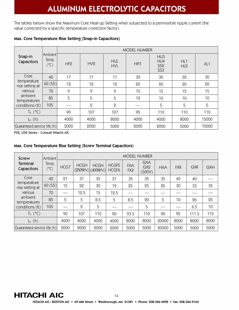
The tables below show the Maximum Core Heat-up Setting when subjected to a permissible ripple current (thevalue corrected by a specific temperature correction factor).
Max. Core Temperature Rise Setting (Snap-in Capacitors)
Coretemperaturerise setting at
variousambient
temperaturesconditions (K)
Guaranteed service life (h)
40
70
85
105
21
15
—
5
—
90
4000
2000
31
22
12.5
5
2
107
4000
2000
35
30
15
8.5
5
110
4000
2000
35
25
—
8.5
—
93.5
8000
5000
35
25
—
20
5
110
8000
5000
35
25
—
5
—
90
20000
20000
40
33
—
26
6.5
111.5
8000
5000
—
35
—
25
10
115
8000
5000
HXA GXHGXRHCG7 HCGH(400W.V.)
FXAFX2
GXAGX2
(500V)
HCGH(250W.V.)
60 (55)
AmbientTemp(°C)
T0 (°C)
L0 (h)
MODEL NUMBERScrewTerminalCapacitors
Coretemperaturerise setting at
variousambient
temperaturesconditions (K)
Guaranteed service life (h)
40
70
85
105
17
12
9
5
—
90
4000
2000
17
12
9
5
2
107
4000
2000
17
12
9
5
2
107
8000
5000
30
20
15
10
—
95
4000
2000
30
20
15
10
5
110
4000
2000
30
20
15
10
5
110
8000
5000
30
20
15
10
5
110
15000
10000
HP3 XL1
HU3HU4SS2SS3
HF2HULHVLHV2
60 (55)
AmbientTemp(°C)
T0 (°C)
L0 (h)
MODEL NUMBER
Snap-inCapacitors HL1
HL2
31
19
12.5
5
—
90
4000
2000
HCGF5HCGF6
40
30
—
10
—
95
8000
5000
FXR
Max. Core Temperature Rise Setting (Screw Terminal Capacitors)
PS2, US2 Series - Consult Hitachi AIC
15
ALUMINUM ELECTROLYTIC CAPACITORS
AICHITACHI AIC / BOSTON AIC • 69 Milk Street • Westborough, MA 01581 • Phone: 508-366-4092 • Fax: 508-366-9164
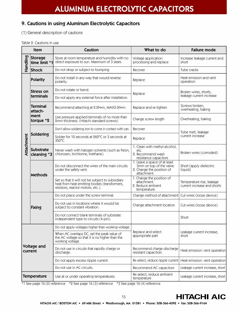
9. Cautions in using Aluminum Electrolytic Capacitors
(1) General description of cautions
Table 2. Cautions in use
Item Caution What to do Failure mode
Storagetime limit *1
Shock
Polarity
Stress onterminals
Terminalattach-menttorque *2
Soldering
Substratecleaning *3
Methods
Fixing
Voltage andcurrent
Temperature
Att
achm
ent
Han
dlin
g
When AC overlaps DC, set the peak value ofthe AC voltage so that it is no higher than theworking voltage.
1. Leave a space of at least 3mm on top of the valve.2. Change the position of attachment.1. Change the position of attachment.2. Reduce ambient temperature.
Store at room temperature and humidity with nodirect exposure to sun. Maximum of 3 years.
Voltage applicationprocessing and replace
Increase leakage current andshort
Do not drop or subject to bumping. Recover Tube cracks
Do not install in any way that would reversepolarity. Replace Heat emission and vent
operation
Do not rotate or bend.
Do not apply any external force after installation.Replace Broken wires, shorts,
leakage current increase
Recommend attaching at 2.2N•m, MAX3.0N•m.
Use pressure applied terminals of no more than2mm thickness. (Hitachi standard screws)
Replace and re-tighten Screws broken,overheating, baking
Change screw length Overheating, baking
Don’t allow soldering iron to come in contact with can. Recover
Solder for 10 seconds at 260°C or 3 seconds at350°C.
Replace
Tube melt, leakagecurrent increase
Never wash with halogen solvents (such as freon,chlorosen, trichlorine, triethane).
1. Clean with methyl alcohol, etc.2. Recommend wash resistance capacitors
Broken wires (corroded)
Do not disconnect the wires of the main circuitsunder the safety vent.
Short (apply dielectricliquid)
Set so that it will not be subject to subsidiaryheat from heat emitting bodies (transformers,resistors, reactor motors, etc.).
Temperature rise, leakagecurrent increase and shorts
Do not place under the screw terminal. Change method of attachment Cut wires (loose device)
Do not use in locations where it would besubject to constant vibration. Change attachment location Cut wires (loose device)
Do not connect blank terminals of substrateindependent type to circuits (4-pin). Short
Do not apply voltages higher than working voltage.Replace and selectappropriate part
Leakage current increase,short
Do not use in circuits that rapidly charge ordischarge.
Recommend charge-dischargeresistant capacitors Heat emission: vent operation
Heat emission: vent operationDo not apply excess ripple current. Re-select, reduce ripple current
Do not use in AC circuits. Recommend AC capacitors Leakage current increase, short
Use at or under operating temperatures. Re-select, reduce ambienttemperature Leakage current increase, short
*1 See page 16 (2) reference *2 See page 16 (3) reference *3 See page 16 (4) reference

16
ALUMINUM ELECTROLYTIC CAPACITORS
AICHITACHI AIC / BOSTON AIC • 69 Milk Street • Westborough, MA 01581 • Phone: 508-366-4092 • Fax: 508-366-9164
(2) Storage time limit (leaving stored with no load). Hitachi performs actual tests with capacitors left with no load at room temperature (1-5 years) and the results show that if these devices are left for three years or less, there is little increase in leakage current, and although there is some increase in leakage current after testing with those that are left three to five years, we have been able to confirm that the increase in temperature calculated here shows that this is not fatal. This shows that if the capacitors are used within three years, there will be no aging. If more than three years passes, we recommend that they be aged under the following conditions.
First, apply 80 percent of working voltage, then 90 percent of working voltage, then finally applyworking voltage for one hour (at room temperature).
(3) Attachment torque of M5 terminals. Table 3 shows the results of measuring torque resistance on screws and terminals by inserting spacers with thicknesses of 1, 2, 3 and 4 millimeters, using M5 X 10 pan screws and testing attachment to the aluminum terminals. Table 3 also shows the relation between tightening torque, spacer thickness and contact resistance.
Table 3. Destruction conditions and torque with different spacer thicknesses.Number of tests (Destruction torque test: 30 for each spacer thickness. Contact resistance measurements: 30for each spacer thickness and torque.)
Destruction torque was steady with spacers of 2mm thickness but at 3mm or greater, the values decreased and there was an increase in the terminal screw top destruction. The contact resistance also increased when the tightening torque was too low (10N•m or less) but stabilized at 1.5N•m or higher. These results allow us to recommend an optimum tightening torque of 2.2N•m and a maximum of 3.0N•m. We also recommend a contact bar thickness of 2mm or less (with M5 X 10 standard screws) and if the value is exceeded, we recommend the use of M5 X 12 or M5 X 15 screws.
(4) Horizontal attachment of screw types and washing resistant capacitors. If standard snap-in terminal aluminum electrloytic capacitors are cleaned with freon, the positive electrode leads will corrode and then break. If the capacitors are cleaned with freon, we recommend using cleaning resistant capacitors. The following are generally used to deal with this problem.
1. Seal the inserting end (rubber boundries, surfaces and terminals) with resin.2. Mix with dielectric liquid additive so that the inserted chlorine does not separate.
There are limits to the mix quantity and type with method 2, according to the type of cleaning agent and cleaning conditions. This is why Hitachi recommends the method of dealing with this problem using the cleaning resistant types in method 1 above. The halogen compounds, including chlorine, are converted by negative ions into positive ions. Hitachi implements thorough chlorine control in its processes, but if you are unsure about the operating environmenrt or the devices are to be horizontally screw-mounted, you should put the positive electrode terminals on top so that dielectric liquid will not leak on the positive electrode leads. (Do not use in halogen environments.)
Destruction torque test Tightening torque and terminal contact resistance (mΩ)
Tightening torque (N•m)Destruction T (N•m) Destruction conditions & numbers
Min
5.6
5.7
5.4
3.8
Max
7.0
6.9
6.0
5.7
X
6.2
6.2
5.7
4.5
Terminal screw top
5
8
15
26
Screw & head cut
25
22
15
4
0.5
0.20
0.24
0.22
0.20
1.0
0.12
0.11
0.13
0.12
1.5
0.07
0.08
0.07
0.07
2.0
0.06
0.07
0.07
0.07
3.0
0.06
0.06
0.06
0.07
4.0
0.06
0.07
0.06
0.10
1
2
3
4
Spacerthickness
(mm)
17
ALUMINUM ELECTROLYTIC CAPACITORS
AICHITACHI AIC / BOSTON AIC • 69 Milk Street • Westborough, MA 01581 • Phone: 508-366-4092 • Fax: 508-366-9164
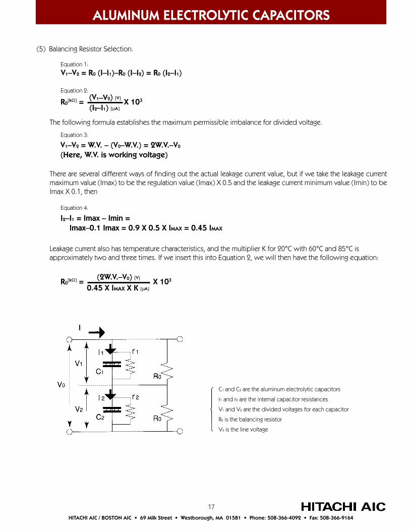
(5) Balancing Resistor Selection.
V1–V2 = R0 (I–I1)–R0 (I–I2) = R0 (I2–I1)Equation 1:
Equation 2:
R0[kΩ] = X 103(V1–V2) [V]
(I2–I1) [µA]
The following formula establishes the maximum permissible imbalance for divided voltage.
V1–V2 = W.V. – (V0–W.V.) = 2W.V.–V0
(Here, W.V. is working voltage)
Equation 3:
There are several different ways of finding out the actual leakage current value, but if we take the leakage currentmaximum value (Imax) to be the regulation value (Imax) X 0.5 and the leakage current minimum value (Imin) to beImax X 0.1, then
I2–I1 = Imax – Imin = Imax–0.1 Imax = 0.9 X 0.5 X IMAX = 0.45 IMAX
Equation 4:
Leakage current also has temperature characteristics, and the multiplier K for 20°C with 60°C and 85°C isapproximately two and three times. If we insert this into Equation 2, we will then have the following equation:
R0[kΩ] = X 103(2W.V.–V0) [V]
0.45 X IMAX X K [µA]
C1 and C2 are the aluminum electrolytic capacitors
r1 and r2 are the internal capacitor resistances
V1 and V2 are the divided voltages for each capacitor
R0 is the balancing resistor
V0 is the line voltage
18
ALUMINUM ELECTROLYTIC CAPACITORS
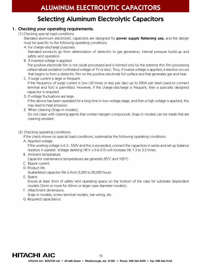
Selecting Aluminum Electrolytic Capacitors1. Checking your operating requirements. (1) Checking special load conditions. Standard aluminum electrolytic capacitors are designed for power supply flattening use, and the design must be specific to the following operating conditions. A. For charge-discharge purposes.
Standard products go from deterioration of dielectric to gas generation, internal pressure build-up and safety vent operation. B. If inverted voltage is applied.
The positive electrode film is not oxide processed and is formed only by the extreme thin film processing called natural oxidation (withstand voltage of 1V or less). Thus, if inverse voltage is applied, a reaction occurs
that begins to form a dielectric film on the positive electrode foil surface and that generates gas and heat. C. If surge current is large or frequent.
If the frequency of surge current is low (30 times or less per day) up to 200A per lead (used to connect terminal and foil) is permitted. However, if the charge-discharge is frequent, then a specially designed capacitor is required.
D. If voltage fluctuations are large. If the device has been operated for a long time in low-voltage stage, and then a high voltage is applied, this may lead to heat emission.
E. When cleaning (Snap-in models). Do not clean with cleaning agents that contain halogen compounds. Snap-in models can be made that are cleaning resistant.
(2) Checking operating conditions. If the check shows no special load conditions, systematize the following operating conditions. A. Applied voltage.
If the working voltage is 6.3 - 550V and this is exceeded, connect the capacitors in series and set up balance resistors in parallel. Voltage deleting (W.V. x 0.6-0.9) will increase life 1.3 to 3.5 times.
B. Ambient temperature. Capacitor maintenance temperatures are generally 85°C and 105°C.
C. Ripple current. D. Product life.
Guaranteed capacitor life is from 2,000 to 20,000 hours. E. Space.
Ensure at least 3mm of safety vent operating space on the bottom of the case for substrate dependent models (5mm or more for 40mm or larger case diameter models).
F. Attachment dimensions. Snap-in models, screw terminal models, bar wiring, etc.
G. Required capacitance.
AICHITACHI AIC / BOSTON AIC • 69 Milk Street • Westborough, MA 01581 • Phone: 508-366-4092 • Fax: 508-366-9164

19
ALUMINUM ELECTROLYTIC CAPACITORS
AICHITACHI AIC / BOSTON AIC • 69 Milk Street • Westborough, MA 01581 • Phone: 508-366-4092 • Fax: 508-366-9164
2. Understanding how Hitachi aluminum electrolytic capacitors are named.
(1) Screw terminal models (Example)
ø symbol With the FX and later models, there are two types of dimension specifications, affix the ø symbol. Not necessary for other models.
Lead shape symbol Y = 3 point fixing. I = 2 point fixing (ø77 and 90 indicate non standard but can be used)Capacitance code 3rd digit indicates the number of zerosVoltage code
Series name
FXA 2G 472 Y D
ø 36 51 64 77 90 100Symbol A C D E F G
Working voltage 50 63 200 250 400 450 500 550 630 Symbol 1H 1J 2D 2E 2G 2W 2H 2L 2J
ø symbol Because the HP3 and HU3 and later models have 2-4 types of dimensions by ø for each specification, attach the ø symbol.
Terminal shape symbols C = 2-Claw Short Terminal R = 2-Claw Terminal U = Straight Short Terminal S = 4-Claw Terminal T = T-TerminalSymbol for difference in permissible capacitance M = ± 20% (general use)Capacitance code 3rd digit indicates the number of zerosVoltage code
Series name
ø 36 51 64 77 90 100Symbol A C D E F G
HU3 2G 151 M R X
(2) Snap-in models (Example)
20
ALUMINUM ELECTROLYTIC CAPACITORS
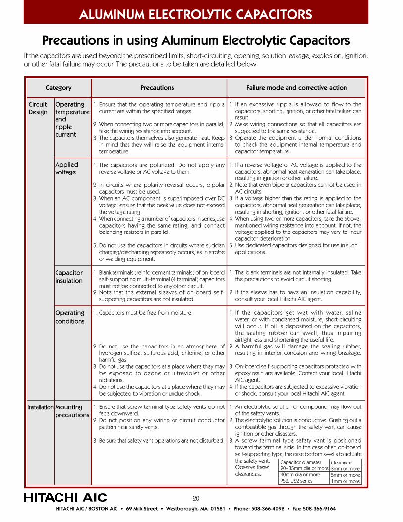
Precautions in using Aluminum Electrolytic CapacitorsIf the capacitors are used beyond the prescribed limits, short-circuiting, opening, solution leakage, explosion, ignition,or other fatal failure may occur. The precautions to be taken are detailed below.
1. Ensure that the operating temperature and ripplecurrent are within the specified ranges.
2. When connecting two or more capacitors in parallel,take the wiring resistance into account.
3. The capacitors themselves also generate heat. Keepin mind that they will raise the equipment internaltemperature.
1. The capacitors are polarized. Do not apply anyreverse voltage or AC voltage to them.
2. In circuits where polarity reversal occurs, bipolarcapacitors must be used.
3. When an AC component is superimposed over DCvoltage, ensure that the peak value does not exceedthe voltage rating.
4. When connecting a number of capacitors in series,usecapacitors having the same rating, and connectbalancing resistors in parallel.
5. Do not use the capacitors in circuits where suddencharging/discharging repeatedly occurs, as in strobeor welding equipment.
1. Blank terminals (reinforcement terminals) of on-boardself-supporting multi-terminal (4 terminal) capacitorsmust not be connected to any other circuit.
2. Note that the external sleeves of on-board self-supporting capacitors are not insulated.
1. Capacitors must be free from moisture.
2. Do not use the capacitors in an atmosphere ofhydrogen sulfide, sulfurous acid, chlorine, or otherharmful gas.
3. Do not use the capacitors at a place where they maybe exposed to ozone or ultraviolet or otherradiations.
4. Do not use the capacitors at a place where they maybe subjected to vibration or undue shock.
1. Ensure that screw terminal type safety vents do notface downward.
2. Do not position any wiring or circuit conductorpattern near safety vents.
3. Be sure that safety vent operations are not disturbed.
1. If an excessive ripple is allowed to flow to thecapacitors, shorting, ignition, or other fatal failure canresult.
2. Make wiring connections so that all capacitors aresubjected to the same resistance.
3. Operate the equipment under normal conditionsto check the equipment internal temperature andcapacitor temperature.
1. If a reverse voltage or AC voltage is applied to thecapacitors, abnormal heat generation can take place,resulting in ignition or other failure.
2. Note that even bipolar capacitors cannot be used inAC circuits.
3. If a voltage higher than the rating is applied to thecapacitors, abnormal heat generation can take place,resulting in shorting, ignition, or other fatal failure.
4. When using two or more capacitors, take the above-mentioned wiring resistance into account. If not, thevoltage applied to the capacitors may vary to incurcapacitor deterioration.
5. Use dedicated capacitors designed for use in suchapplications.
1. The blank terminals are not internally insulated. Takethe precautions to avoid circuit shorting.
2. If the sleeve has to have an insulation capability,consult your local Hitachi AIC agent.
1. If the capacitors get wet with water, salinewater, or with condensed moisture, short-circuitingwill occur. If oil is deposited on the capacitors,the sealing rubber can swell, thus impairingairtightness and shortening the useful life.
2. A harmful gas will damage the sealing rubber,resulting in interior corrosion and wiring breakage.
3. On-board self-supporting capacitors protected withepoxy resin are available. Contact your local HitachiAIC agent.
4. If the capacitors are subjected to excessive vibrationor shock, consult your local Hitachi AIC agent.
1. An electrolytic solution or compound may flow outof the safety vents.
2. The electrolytic solution is conductive. Gushing out acombustible gas through the safety vent can causeignition or other disasters.
3. A screw terminal type safety vent is positionedtoward the terminal side. In the case of an on-boardself-supporting type, the case bottom swells to actuatethe safety vent.Observe theseclearances.
CircuitDesign
Operatingtemperatureandripplecurrent
Appliedvoltage
Capacitorinsulation
Operatingconditions
Mountingprecautions
Category Precautions Failure mode and corrective action
AICHITACHI AIC / BOSTON AIC • 69 Milk Street • Westborough, MA 01581 • Phone: 508-366-4092 • Fax: 508-366-9164
Installation
Capacitor diameter20~35mm dia or more40mm dia or morePS2, US2 series
Clearance3mm or more5mm or more1mm or more

21
ALUMINUM ELECTROLYTIC CAPACITORS
1. Properly insert the capacitors into the wiring board.The capacitor should be flush with the printed circuitboard.
2. Ensure that the flux is not applied to areas otherthan the terminals.
3. Soldering must be conducted within 10 seconds at260°C or within 3 seconds at 350°C.
4. For washing off the flux,the use of water-soluble orhigh grade alcoholic cleaning agent or isopropylalcohol is recommended. It is also recommended thatthe flux concentration be 2wt% relative to thecleaning agent.
5. After the use of cleaning solution, it must be allowedto dry. Even when the flux is not to be removed,allow it to dry.
6. When securing a capacitor to a circuit board with acoating or fixing material, be sure that the employedcoating or fixing material does not contain halogencompounds. Before coating the capacitor, allow theflux or cleaning agent to dry completely.
7. When securing a capacitor to a circuit board with acoating or fixing material, use care so that the sealedend of the capacitor is not entirely covered. Ensure,also that no coating or fixing material is applied tothe safety vent section at the bottom of thecapacitor. When conducting overall coating, consultyour local Hitachi AIC agent.
1. Tighten terminal screws appropriately and maintainpermissible terminal currents.
2. Use appropriate terminal screws.
3. Follow recommended bar hole diameter.
Priorknowledgeofmounting
Snap-incapacitors
Screwterminalcapacitors
Installation
Category Precautions Failure mode and corrective action
1. Use care to avoid polarity reversal.
2. Ensure that the curled section (sealed end of the case)is not stressed.
3. Use extreme care in handling the capacitors.
4. Never reuse a capacitor which has been installed and energized.
1. If a reverse voltage is applied to the capacitors, theymust not be used any longer. Even if they have noapparent defects, they are seriously damaged.
2. Do not tighten the curled section with a band or thelike because solution leakage or sleeve cutting canresult.
3. If the capacitors fall on the floor or bump against anyobject, their external surfaces and internal structurecan be rendered abnormal, resulting in electricalperformance deterioration or destruction. Replacesuch capacitors.
4. No capacitor can be reused except for those removed tomeasure their electric performance for a periodic checkup.
1. If the capacitors are soldered while they are notflush with the wiring board, terminal breakage orconductive pattern separation can be caused bymechanical vibration or shock.
2. If the flux comes into contact with the sealing rubbersurface, corrosion can be caused by the halogencompound in the flux.
3. If soldering is conducted without satisfying theprescribed conditions, the capacitors will be thermallystressed so that electrical characteristic deteriorationor other problem can occur.
4. If the flux concentration in the cleaning solution rises,the halogen concentration also increases. Therefore,corrosion can occur as indicated in paragraph 2above.
5. If any cleaning solution or flux remains between thecircuit board and capacitor, the halogen compoundcan permeate into the sealing rubber, resulting incorrosion.
6. If the employed coating or fixing material contains ahalogen compound, corrosion can take place.
7. If the overall coating method is employed, the flux orcleaning solution halogen compound residue isconfined so that corrosion can occur. If a coating or afixing material is applied to the safety vent section,the safety vent operations will be obstructed.
1.
2. Terminal screws furnished in a separate shipment aregeared to wires no more than 2mm thick. For wiresmore than 2mm thick, ensure a screw length allowingfor that thickness.
3. Hitachi AIC recommends a bar hole diameter of 6mmfor M5. An excessively large hole diameter may resultin poor contact between the terminal surface and bar,causing a local heat-up and eventual breakdown.
AIC
Precautions in using Aluminum Electrolytic Capacitors
HITACHI AIC / BOSTON AIC • 69 Milk Street • Westborough, MA 01581 • Phone: 508-366-4092 • Fax: 508-366-9164
Terminal
M5M6M8
Recommended Torque(permissible level)
2.2 (1.5 ~ 3.0)3.0 (3.0 ~ 3.5)7.5 (7.0 ~ 8.0)
PermissibleTerminal Current
60100120

22
ALUMINUM ELECTROLYTIC CAPACITORS
Precautions in using Aluminum Electrolytic Capacitors
1. Before allowing the capacitors to conduct, mountthem on a chassis.
1. Capacitors used in industrial equipment must beinspected on a periodic basis. The inspection itemsare as follows:(1) Appearance (e.g., safety vent condition)(2) Electrical performance (e.g., capacitance, powerloss, current leakage)
2. If the capacitors have reached the end of their life,they must be replaced.
1. The capacitors must be stored at 5 to 35°C, less than75% R.H. and kept out of direct sunlight. Themaximum storage period is three years.
2. There may be cases where an electric charge isgenerated due to transient phenomena. To avoidelectrical shock hazard, do not touch the terminalswith bare hands.
1. When disposing of the capacitors, punch holes orcrush the case and then incinerate them.
2. When the capacitors are not to be incinerated,consult the EPA for the proper disposal of industrialwaste.
1. If any abnormally high voltage is applied to thecapacitors, they can explode.
1. Before performing periodic maintenance tasks, turnOFF the equipment and allow the capacitors tocompletely discharge.
2. If any capacitor in equipment needs to be replaced,replace all the capacitors used in the sameequipment. If new and old ones are used together,an unbalanced ripple current or voltage sharing canresult.
1. After the capacitors have been stored for a period ofmore than 3 years, reforming will be necessary.
2. Before touching the terminals, discharge them with aresistor (10 to 100Ω) or discharge plate.
1. If an attempt is made to incinerate the capacitorswithout punching holes or crushing their cases, theywill explode, resulting in a safety hazard. Be sure thatincineration is conducted at high temperature. If it isdone at low temperature, chlorine or otherpoisonous gas may be generated from the externalsleeves (made of polyvinyl chloride).
2. When the capacitors are disposed of by an industrialwaste disposal agent, verify that they are properlyburied. Ensure that no discarded capacitors will beput back on the market.
Duringuse
Preventivemaintenance
Notes onstoringcapacitors
Disposal
Other
Test run
Category Precautions Failure mode and corrective action
AIC
1. For further details refer to EIAJ RCR-2367, Precautions and Guidelines for Using Electronic Device FixedAluminum Nonsolid Electrolytic Capacitors.
2. If you have any questions, feel free to contact your local Hitachi AIC agent.
HITACHI AIC / BOSTON AIC • 69 Milk Street • Westborough, MA 01581 • Phone: 508-366-4092 • Fax: 508-366-9164
IN AN EMERGENCY1. If gas is detected when installed capacitors are used, turn off the main power to the installation or unplug the power cord from the wall outlet.2. When the safety vent of a capacitor is activated, a hot gas exceeding 100°C will jet out. Do not get close to, or expose yourself to the gas. Otherwise severe injury may occur.3. If a gas jet enters your eye, wash it immediately with clean water.4. If electrolyte gets in contact with your skin, wash the area of you skin with soap and water. Never allow electrolyte to enter your mouth.
23
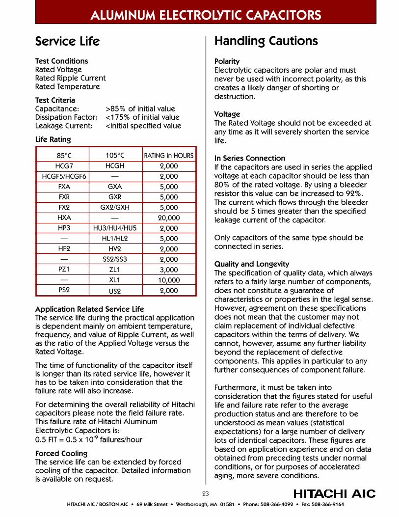
Test ConditionsRated VoltageRated Ripple CurrentRated Temperature
Test CriteriaCapacitance: >85% of initial valueDissipation Factor: <175% of initial valueLeakage Current: <Initial specified value
Life Rating
Application Related Service LifeThe service life during the practical applicationis dependent mainly on ambient temperature,frequency, and value of Ripple Current, as wellas the ratio of the Applied Voltage versus theRated Voltage.
The time of functionality of the capacitor itselfis longer than its rated service life, however ithas to be taken into consideration that thefailure rate will also increase.
For determining the overall reliability of Hitachicapacitors please note the field failure rate.This failure rate of Hitachi AluminumElectrolytic Capacitors is:0.5 FIT = 0.5 x 10⁻⁹ failures/hour
Forced CoolingThe service life can be extended by forcedcooling of the capacitor. Detailed informationis available on request.
105°CHCGH
—
GXAGXR
GX2/GXH—
HU3/HU4/HU5HL1/HL2
HV2SS2/SS3
ZL1
XL1
US2
ALUMINUM ELECTROLYTIC CAPACITORS
AICHITACHI AIC / BOSTON AIC • 69 Milk Street • Westborough, MA 01581 • Phone: 508-366-4092 • Fax: 508-366-9164
PolarityElectrolytic capacitors are polar and mustnever be used with incorrect polarity, as thiscreates a likely danger of shorting ordestruction.
VoltageThe Rated Voltage should not be exceeded atany time as it will severely shorten the servicelife.
In Series ConnectionIf the capacitors are used in series the appliedvoltage at each capacitor should be less than80% of the rated voltage. By using a bleederresistor this value can be increased to 92%.The current which flows through the bleedershould be 5 times greater than the specifiedleakage current of the capacitor.
Only capacitors of the same type should beconnected in series.
Quality and LongevityThe specification of quality data, which alwaysrefers to a fairly large number of components,does not constitute a guarantee ofcharacteristics or properties in the legal sense.However, agreement on these specificationsdoes not mean that the customer may notclaim replacement of individual defectivecapacitors within the terms of delivery. Wecannot, however, assume any further liabilitybeyond the replacement of defectivecomponents. This applies in particular to anyfurther consequences of component failure.
Furthermore, it must be taken intoconsideration that the figures stated for usefullife and failure rate refer to the averageproduction status and are therefore to beunderstood as mean values (statisticalexpectations) for a large number of deliverylots of identical capacitors. These figures arebased on application experience and on dataobtained from preceding tests under normalconditions, or for purposes of acceleratedaging, more severe conditions.
Handling Cautions
85°CHCG7
HCGF5/HCGF6FXAFXRFX2HXAHP3—
HF2—
PZ1—
PS2
RATING in HOURS
2,0002,000
5,0005,000
5,00020,000
2,0005,000
2,0002,000
3,00010,000
2,000
Service Life
24
ALUMINUM ELECTROLYTIC & FILM CAPACITORS
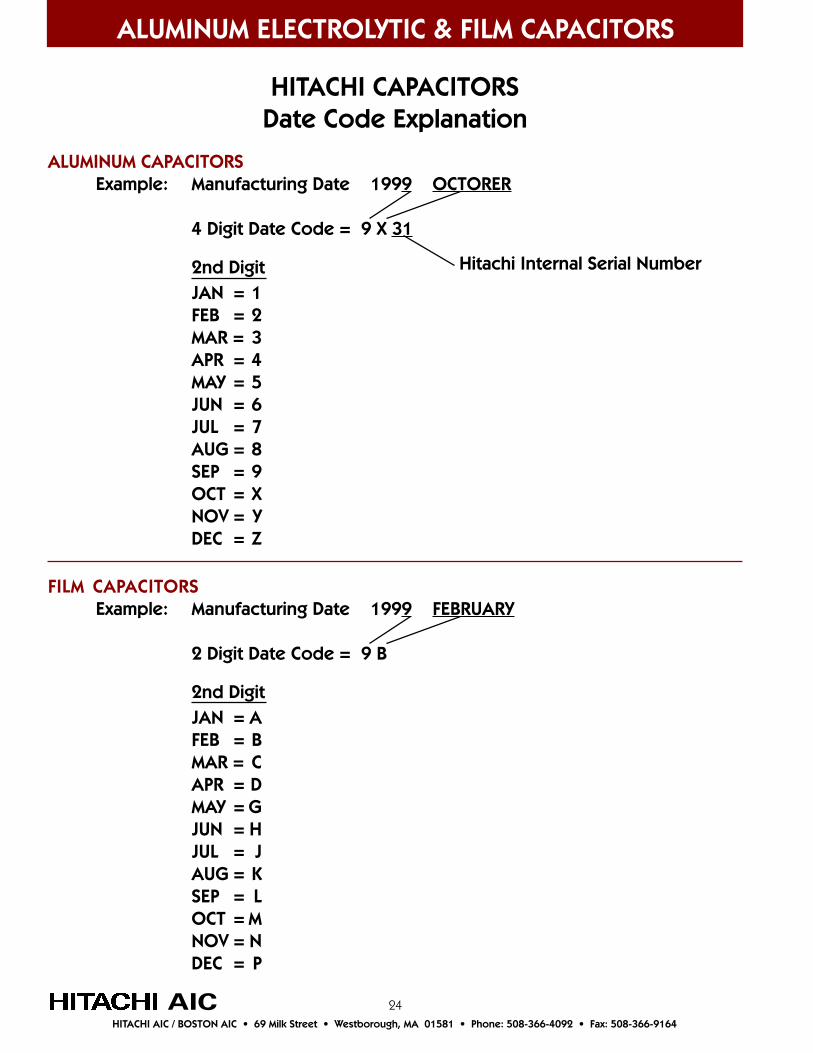
HITACHI CAPACITORSDate Code Explanation
ALUMINUM CAPACITORSExample: Manufacturing Date 1999 OCTORER
4 Digit Date Code = 9 X 31
Hitachi Internal Serial Number2nd DigitJAN = 1FEB = 2MAR = 3APR = 4MAY = 5JUN = 6JUL = 7AUG = 8SEP = 9OCT = XNOV = YDEC = Z
FILM CAPACITORSExample: Manufacturing Date 1999 FEBRUARY
2 Digit Date Code = 9 B
2nd DigitJAN = AFEB = BMAR = CAPR = DMAY = GJUN = HJUL = JAUG = KSEP = LOCT = MNOV = NDEC = P
AICHITACHI AIC / BOSTON AIC • 69 Milk Street • Westborough, MA 01581 • Phone: 508-366-4092 • Fax: 508-366-9164
25
ALUMINUM ELECTROLYTIC CAPACITORS
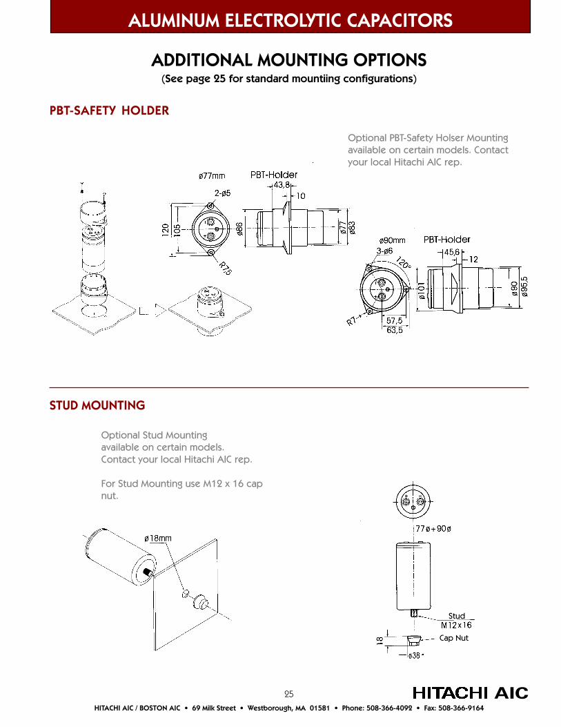
ADDITIONAL MOUNTING OPTIONS(See page 25 for standard mountiing configurations)
PBT-SAFETY HOLDER
STUD MOUNTING
Optional PBT-Safety Holser Mountingavailable on certain models. Contactyour local Hitachi AIC rep.
Optional Stud Mountingavailable on certain models.Contact your local Hitachi AIC rep.
For Stud Mounting use M12 x 16 capnut.
AICHITACHI AIC / BOSTON AIC • 69 Milk Street • Westborough, MA 01581 • Phone: 508-366-4092 • Fax: 508-366-9164
Stud
Cap Nut

26
Large Can Capacitors with Screw Terminals
Product Numbering System for HCG7 and HCGH SeriesExample: HCG7 Series, A terminals, 6.3V, 220,000µF ±20%, Y bracket, 51 x 100mm
This Section Contains:HCG7 Series – 2000 hours at 85°C.15% smaller than HCG6 series is achieved through developmentof foil technology, yet has the same permissible ripple currentcapability.HCGH Series – 2000 hours at 105°C.Small size, large power, high ripple current.HCGF5 Series – 2000 hours at 85°C. High ripple type forinverters has been supplied as standard for years.HCGF6 Series – 2000 hours at 85°C.Large capacitance type for inverters. 14% smaller than HCGF5.High voltage series from 400-500VDC.FXA Series – 5000 hours at 85°C.
FX2 Series – 5000 hours at 85°C.
FXR Series – 5000 hours at 85°C.
GXA Series – 5000 hours at 105°C.
GX2 Series – 5000 hours at 105°C.
GXH Series – 5000 hours at 105°C.
GXR Series – 5000 hours at 105°C.
HXA Series – 20000 hours at 85°C.Use of liquid organic acid, improved foil and etchingtechnology enable a long life and high ripple current.
ALUMINUM ELECTROLYTIC CAPACITORS
AIC
Case code
Type of bracket (Y or I)
Capacitance code
Rated Voltage code
Terminal code (A=screw)
Series Name
HCG7 A 0J 224 Y C10
Capacitance Code: To determine Capacitance code use the first 2 digits of the Capacitancefollowed by the number of zeros. Using the above example of 220,000: 22 + 4 zeros = 224.
Hitachi technology hasreduced the size ofmany of its large cancapacitors to give youmore room in yourapplication.
HITACHI AIC / BOSTON AIC • 69 Milk Street • Westborough, MA 01581 • Phone: 508-366-4092 • Fax: 508-366-9164
27
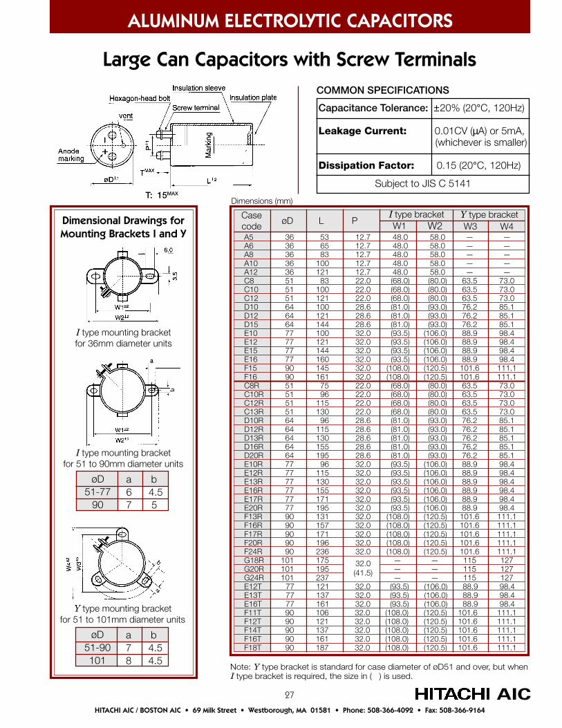
A5 36 53 12.7 48.0 58.0 — —A6 36 65 12.7 48.0 58.0 — —A8 36 83 12.7 48.0 58.0 — —A10 36 100 12.7 48.0 58.0 — —A12 36 121 12.7 48.0 58.0 — —C8 51 83 22.0 (68.0) (80.0) 63.5 73.0C10 51 100 22.0 (68.0) (80.0) 63.5 73.0C12 51 121 22.0 (68.0) (80.0) 63.5 73.0D10 64 100 28.6 (81.0) (93.0) 76.2 85.1D12 64 121 28.6 (81.0) (93.0) 76.2 85.1D15 64 144 28.6 (81.0) (93.0) 76.2 85.1E10 77 100 32.0 (93.5) (106.0) 88.9 98.4E12 77 121 32.0 (93.5) (106.0) 88.9 98.4E15 77 144 32.0 (93.5) (106.0) 88.9 98.4E16 77 160 32.0 (93.5) (106.0) 88.9 98.4F15 90 145 32.0 (108.0) (120.5) 101.6 111.1F16 90 161 32.0 (108.0) (120.5) 101.6 111.1C8R 51 75 22.0 (68.0) (80.0) 63.5 73.0C10R 51 96 22.0 (68.0) (80.0) 63.5 73.0C12R 51 115 22.0 (68.0) (80.0) 63.5 73.0C13R 51 130 22.0 (68.0) (80.0) 63.5 73.0D10R 64 96 28.6 (81.0) (93.0) 76.2 85.1D12R 64 115 28.6 (81.0) (93.0) 76.2 85.1D13R 64 130 28.6 (81.0) (93.0) 76.2 85.1D16R 64 155 28.6 (81.0) (93.0) 76.2 85.1D20R 64 195 28.6 (81.0) (93.0) 76.2 85.1E10R 77 96 32.0 (93.5) (106.0) 88.9 98.4E12R 77 115 32.0 (93.5) (106.0) 88.9 98.4E13R 77 130 32.0 (93.5) (106.0) 88.9 98.4E16R 77 155 32.0 (93.5) (106.0) 88.9 98.4E17R 77 171 32.0 (93.5) (106.0) 88.9 98.4E20R 77 195 32.0 (93.5) (106.0) 88.9 98.4F13R 90 131 32.0 (108.0) (120.5) 101.6 111.1F16R 90 157 32.0 (108.0) (120.5) 101.6 111.1F17R 90 171 32.0 (108.0) (120.5) 101.6 111.1F20R 90 196 32.0 (108.0) (120.5) 101.6 111.1F24R 90 236 32.0 (108.0) (120.5) 101.6 111.1G18R 101 175 — — 115 127G20R 101 195 — — 115 127G24R 101 237 — — 115 127E12T 77 121 32.0 (93.5) (106.0) 88.9 98.4E13T 77 137 32.0 (93.5) (106.0) 88.9 98.4E16T 77 161 32.0 (93.5) (106.0) 88.9 98.4F11T 90 106 32.0 (108.0) (120.5) 101.6 111.1F12T 90 121 32.0 (108.0) (120.5) 101.6 111.1F14T 90 137 32.0 (108.0) (120.5) 101.6 111.1F16T 90 161 32.0 (108.0) (120.5) 101.6 111.1F18T 90 187 32.0 (108.0) (120.5) 101.6 111.1
Capacitance Tolerance: ±20% (20°C, 120Hz)
Leakage Current: 0.01CV (µA) or 5mA, (whichever is smaller)
Dissipation Factor: 0.15 (20°C, 120Hz)
COMMON SPECIFICATIONS
Subject to JIS C 5141
Dimensional Drawings forMounting Brackets I and Y
Y type mounting bracketfor 51 to 101mm diameter units
I type mounting bracketfor 51 to 90mm diameter units
I type mounting bracketfor 36mm diameter units
Large Can Capacitors with Screw Terminals
ALUMINUM ELECTROLYTIC CAPACITORS
AIC
W1 W2 W3 W4øD L P
Casecode
I type bracket Y type bracket
Dimensions (mm)
Note: Y type bracket is standard for case diameter of øD51 and over, but whenI type bracket is required, the size in ( ) is used.
øD51-77
90
a b6 4.57 5
øD51-90101
a b7 4.58 4.5
HITACHI AIC / BOSTON AIC • 69 Milk Street • Westborough, MA 01581 • Phone: 508-366-4092 • Fax: 508-366-9164
T: 15MAX
32.0(41.5)
28
detaRegatloV)CDVW(
traPrebmuN
ecnaticapaCeziSesaC
)mm(LxDØ
elppiRmumixaMtnerruC A( smr )
zH021,C°04@
mumixaM(RSE mΩ)
lacipyT)Hn(LSE
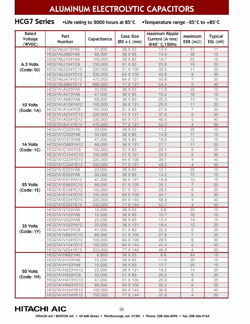
5AY374J0A7GCH 000,74 35X63 4.31 74 116AY386J0A7GCH 000,86 56X63 8.41 33 518AY401J0A7GCH 000,001 38X63 7.91 22 518CY451J0A7GCH 000,051 38X15 6.52 51 02
01CY422J0A7GCH 000,022 001X15 5.33 11 5201DY433J0A7GCH 000,033 001X46 6.34 8 0321DY474J0A7GCH 000,074 121X46 8.05 7 5321EY486J0A7GCH 000,086 121X77 4.45 5 04
5AY333A1A7GCH 000,33 35X63 9.11 52 016AY374A1A7GCH 000,74 56X63 2.51 81 518AY386A1A7GCH 000,86 38X63 3.02 31 51
21AY401A1A7GCH 000,001 121X63 0.52 11 028CY451A1A7GCH 000,051 38X15 6.72 7 52
21CY422A1A7GCH 000,022 121X15 6.73 5 5321DY433A1A7GCH 000,033 121X46 5.64 5 0421EY474A1A7GCH 000,074 121X77 0.25 4 05
5AY322C1A7GCH 000,22 35X63 2.11 52 016AY333C1A7GCH 000,33 56X63 8.41 71 518AY374C1A7GCH 000,74 38X63 6.91 21 51
21AY386C1A7GCH 000,86 121X63 7.72 11 028CY401C1A7GCH 000,001 38X15 4.92 8 52
21CY451C1A7GCH 000,051 121X15 0.43 5 5301DY422C1A7GCH 000,022 001X46 7.93 4 5421EY433C1A7GCH 000,033 121X77 2.94 4 05
6AY322E1A7GCH 000,22 56X63 1.21 22 018AY333E1A7GCH 000,33 38X83 2.41 51 51
21AY374E1A7GCH 000,74 121X63 8.91 01 5101CY386E1A7GCH 000,86 001X15 1.52 7 0221CY401E1A7GCH 000,001 121X15 5.82 6 5201DY451E1A7GCH 000,051 001X46 7.43 5 0351DY422E1A7GCH 000,022 441X46 9.84 4 0451EY433E1A7GCH 000,033 441X77 7.25 3 05
5AY301V1A7GCH 000,01 35X63 6.9 02 016AY351V1A7GCH 000,51 56X63 7.01 61 018AY322V1A7GCH 000,22 38X63 4.31 41 51
21AY333V1A7GCH 000,33 121X63 4.91 21 028CY374V1A7GCH 000,74 38X15 5.22 8 02
01CY386V1A7GCH 000,86 001X15 6.72 7 5201DY401V1A7GCH 000,001 001X46 5.92 6 0351DY451V1A7GCH 000,051 441X46 4.14 5 5451EY422V1A7GCH 000,222 441X77 8.64 4 05
5AY286H1A7GCH 008,6 35X63 8.8 44 516AY301H1A7GCH 000,01 56X63 6.11 03 518AY351H1A7GCH 000,51 38X63 7.21 02 51
21AY322H1A7GCH 000,22 121X63 2.81 41 028CY333H1A7GCH 000,33 38X15 3.02 9 02
01CY374H1A7GCH 000,74 001X15 9.52 8 5201DY386H1A7GCH 000,86 001X46 2.23 6 5351DY401H1A7GCH 000,001 441X46 8.63 5 5451EY451H1A7GCH 000,051 441X77 8.73 4 05
6.3 Volts(Code: 0J)
50 Volts(Code: 1H)
35 Volts(Code: 1V)
25 Volts(Code: 1E)
16 Volts(Code: 1C)
10 Volts(Code: 1A)
HCG7 Series •Life rating to 2000 hours at 85°C •Temperature range –25°C to +85°C
ALUMINUM ELECTROLYTIC CAPACITORS
AICHITACHI AIC / BOSTON AIC • 69 Milk Street • Westborough, MA 01581 • Phone: 508-366-4092 • Fax: 508-366-9164
A
29
ALUMINUM ELECTROLYTIC CAPACITORS
AIC
250 Volts(Code: 2E)
200 Volts(Code: 2D)
160 Volts(Code: 2C)
100 Volts(Code: 2A)
80 Volts(Code: 1K)
63 Volts(Code: 1J)
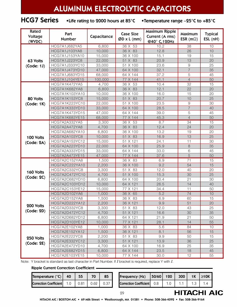
Note: Y bracket is standard as last character in Part Number. If I bracket is required, replace Y with I.
HCG7 Series •Life rating to 2000 hours at 85°C •Temperature range –25°C to +85°C
Temperature (°C) 40 55 70 85
Correction Coefficient 1.0 0.81 0.62 0.37
Frequency (Hz) 50/60 120 300 1K ≥10K
Correction Coefficient 0.8 1.0 1.1 1.3 1.4
Ripple Current Correction Coefficient
HITACHI AIC / BOSTON AIC • 69 Milk Street • Westborough, MA 01581 • Phone: 508-366-4092 • Fax: 508-366-9164
detaRegatloV)CDVW(
traPrebmuN
ecnaticapaCeziSesaC
)mm(LxDØ
elppiRmumixaMtnerruC A( smr )
zH021,C°04@
mumixaM(RSE m )Ω
lacipyT)Hn(LSE
Y286J1A7GCH 5A 008,6 35X63 2.01 83 01Y301J1A7GCH 8A 000,01 38X63 8.21 62 01Y351J1A7GCH 01A 000,51 001X63 1.51 91 51Y322J1A7GCH 8C 000,22 38X15 9.02 31 02Y333J1A7GCH 01C 000,33 001X15 6.32 9 52Y374J1A7GCH 01D 000,74 001X46 1.23 7 53Y386J1A7GCH 51D 000,86 441X46 2.73 5 54Y401J1A7GCH 51E 000,001 441X77 1.14 4 05Y274K1A7GCH 5A 007,4 35X63 4.01 23 51Y286K1A7GCH 8A 008,6 38X63 1.21 22 02Y301K1A7GCH 01A 000,01 001X63 0.61 51 02Y351K1A7GCH 8C 000,51 38X15 7.02 01 52Y322K1A7GCH 01C 000,22 001X15 5.32 9 03Y333K1A7GCH 01D 000,33 001X46 5.82 7 04Y374K1A7GCH 51D 000,74 441X46 0.93 5 54Y386K1A7GCH 51E 000,86 441X77 3.54 4 05Y233A2A7GCH 5A 003,3 35X63 7.8 43 51Y274A2A7GCH 8A 007,4 38X63 4.21 42 02Y286A2A7GCH 01A 008,6 001X63 2.31 91 02Y301A2A7GCH 8C 000,01 38X15 9.61 31 52Y351A2A7GCH 21C 000,51 121X15 1.42 11 03Y322A2A7GCH 01D 000,22 001X46 9.52 8 53Y333A2A7GCH 51D 000,33 441X46 0.33 6 54Y374A2A7GCH 51E 000,74 441X77 6.73 5 05Y251C2A7GCH 8A 005,1 38X63 9.6 17 51Y222C2A7GCH 01A 002,2 001X63 2.9 45 51Y233C2A7GCH 8C 003,3 38X15 0.21 04 02Y274C2A7GCH 01C 007,4 001X15 3.51 03 52Y286C2A7GCH 01D 008,6 001X46 4.02 12 03Y301C2A7GCH 21D 000,01 121X46 5.62 41 04Y351C2A7GCH 21E 000,51 121X77 4.43 11 05Y201D2A7GCH 6A 000,1 56X63 2.5 47 01Y251D2A7GCH 8A 005,1 38X63 9.6 06 51Y222D2A7GCH 21A 002,2 121X63 9.9 15 02Y233D2A7GCH 8C 003,3 38X15 0.21 34 52Y274D2A7GCH 21C 007,4 121X15 6.61 03 53Y286D2A7GCH 21D 008,6 121X46 9.12 12 05Y301D2A7GCH 21E 000,01 121X77 1.82 41 55Y201E2A7GCH 8A 000,1 38X63 6.5 48 01Y251E2A7GCH 21A 005,1 121X63 1.8 65 51Y222E2A7GCH 8C 002,2 38X15 9.9 05 51Y233E2A7GCH 21C 003,3 121X15 9.31 63 52Y274E2A7GCH 01D 007,4 6 001X4 9.61 52 53Y286E2A7GCH 51D 008,6 441X46 5.32 81 54Y301E2A7GCH 51E 000,01 441X77 0.03 21 55
30
detaRegatloV)CDVW(
traPrebmuN
ecnaticapaCeziSesaC
)mm(LxDØ
elppiRmumixaMtnerruC A( smr )
@ 501 zH021,C°
mumixaM(RSE mΩ)
lacipyT)Hn(LSE
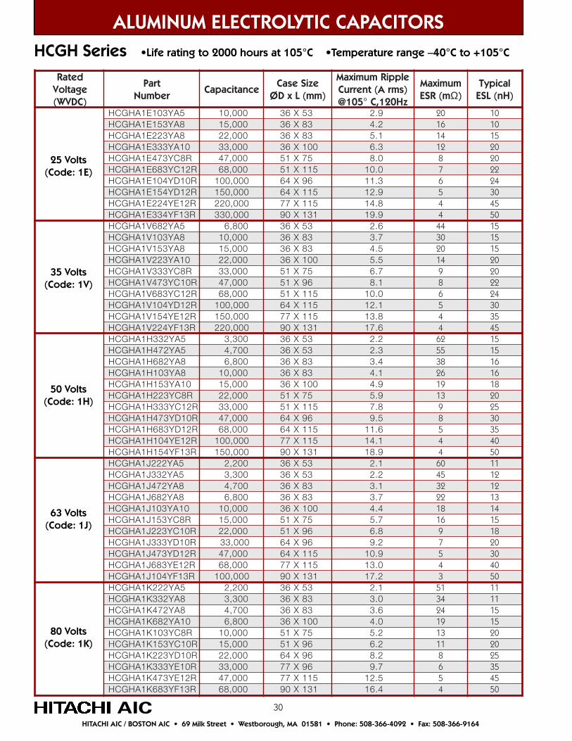
Y301E1AHGCH 5A 01 000, 35X63 9.2 02 01GCH 8AY351E1AH 51 000, X63 38 2.4 61 01GCH 322E1AH Y 8A 000,22 38X63 1.5 41 51GCH 333E1AH Y 01A 33 000, 63 X 001 3.6 21 02GCH 374E1AH Y R8C 74 000, X15 57 0.8 8 02GCH 386E1AH Y R21C 86 000, 15 1X 51 0.01 7 22GCH 401E1AH Y R01D 01 000,0 X46 69 3.11 6 42GCH 451E1AH Y R21D 51 000,0 46 1X 51 9.21 5 03GCH 422E1AH Y R21E 000,022 77 X 511 8.41 4 54GCH 433E1AH Y R31F 033 000, 09 X 131 9.91 4 05GCH 286V1AH Y 5A 008,6 X63 53 6.2 44 51GCH 301V1AH Y 8A 1 000,0 X63 38 7.3 03 51GCH 351V1AH Y 8A 000,51 63 38X 5.4 02 51GCH 322V1AH Y 01A 000,22 63 1X 00 5.5 41 02GCH 333V1AH Y R8C 000,33 15 X 57 7.6 9 02GCH 374V1AH Y R01C 000,74 15 X 69 1.8 8 22GCH 386V1AH Y R21C 86 000, 15 X 511 0.01 6 42GCH 401V1AH Y R21D 001 000, 46 X 511 1.21 5 03GCH 451V1AH Y R21E 051 000, 77 X 511 8.31 4 53GCH 422V1AH Y R31F 022 000, 09 1X 31 6.71 4 54GCH 233H1AH Y 5A 3,3 00 63 X 53 2.2 26 51GCH 274H1AH Y 5A 7,4 00 63 X 35 3.2 55 51GCH 286H1AH Y 8A 8,6 00 63 X 38 4.3 83 61GCH 301H1AH Y 8A 1 000,0 63 X 38 1.4 62 61GCH 351H1AH Y 01A 51 000, 63 X 001 9.4 91 81GCH 322H1AH Y R8C 22 000, 15 X 57 9.5 31 02GCH 333H1AH Y R21C 33 000, 15 X 511 8.7 9 52GCH 374H1AH Y R01D 74 000, 46 X 69 5.9 8 03GCH 386H1AH Y R21D 86 000, 46 X 511 6.11 5 53GCH 401H1AH Y R21E 10 000,0 511X77 1.41 4 04GCH 451H1AH Y R31F 51 000,0 09 1X 13 9.81 4 05GCH 222J1AH Y 5A 2,2 00 63 X 35 1.2 06 11GCH 5AY233J1AH 3,3 00 35X63 2.2 54 21GCH 274J1AH Y 8A 7,4 00 X63 38 1.3 23 21GCH 286J1AH Y 8A 8,6 00 38X63 7.3 22 31GCH 301J1AH Y 01A 01 000, 1X63 00 4.4 81 41GCH 351J1AH Y R8C 51 000, X15 57 7.5 61 51GCH 322J1AH Y R01C 000,22 X15 69 8.6 9 81GCH 333J1AH Y R01D 000,33 X46 69 2.9 7 02GCH 374J1AH Y R21D 74 000, 1X46 51 9.01 5 03GCH 386J1AH Y R21E 86 000, 1X77 51 0.31 4 04GCH 401J1AH Y R31F 0,001 00 09 X 131 2.71 3 05GCH 222K1AH Y 5A 2,2 00 X63 35 1.2 15 11GCH 233K1AH Y 8A 3,3 00 X63 38 0.3 43 11GCH 274K1AH Y 8A 7,4 00 X63 38 6.3 42 51GCH 286K1AH Y 01A 8,6 00 63 X 001 0.4 91 51GCH 301K1AH Y R8C 01 000, X15 57 2.5 31 02GCH 351K1AH Y R01C 51 000, 15 X 69 2.6 11 02GCH 322K1AH Y R01D 22 000, X46 69 2.8 8 52GCH 333K1AH Y R01E 33 000, X77 69 7.9 6 53
R21EY374K1AHGCH 000,74 511X77 5.21 5 54R31FY386K1AHGCH 000,86 131X09 4.61 4 05
ALUMINUM ELECTROLYTIC CAPACITORS
25 Volts(Code: 1E)
80 Volts(Code: 1K)
63 Volts(Code: 1J)
50 Volts(Code: 1H)
35 Volts(Code: 1V)
AIC
HCGH Series •Life rating to 2000 hours at 105°C •Temperature range –40°C to +105°C
HITACHI AIC / BOSTON AIC • 69 Milk Street • Westborough, MA 01581 • Phone: 508-366-4092 • Fax: 508-366-9164
31
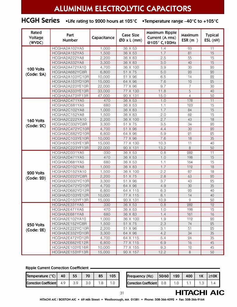
ALUMINUM ELECTROLYTIC CAPACITORSHCGH Series •Life rating to 2000 hours at 105°C •Temperature range –40°C to +105°C
AIC
detaRegatloV)CDVW(
traPrebmuN
ecnaticapaCeziSesaC
)mm(LxDØ
elppiRmumixaMtnerruC A( smr )
@ 501 zH021,C°
mumixaM(RSE m )
lacipyT)Hn(LSE
AHGCH A2 Y201 5A 1 000, 35X63 4.1 39 11GCH 5AY251A2AH 1 5, 00 X63 35 7.1 18 51GCH 222A2AH Y 8A 2 2, 00 38X63 5.2 55 51GCH 233A2AH Y 8A 3 3, 00 63 X 38 0.3 04 51GCH 274A2AH Y 01A 4 7, 00 63 X 001 9.3 03 02GCH 286A2AH Y R8C 6 8, 00 15 X 57 0.5 02 02GCH 301A2AH Y R01C 01 000, 15 X 69 5.6 41 22GCH 351A2AH Y R01D 51 000, 46 X 69 6.7 01 52GCH 322A2AH Y R01E 000,22 77 X 69 7.9 7 03GCH 333A2AH Y R31E 33 000, 77 X 031 8.11 5 04GCH 374A2AH Y R31F 0,74 00 09 131X 0.51 4 05GCH 174C2AH Y 5A 74 0 X63 35 0.1 871 11GCH 186C2AH Y 5A 86 0 63 X 53 1.1 321 51GCH 201C2AH Y 8A 0,1 00 63 X 38 7.1 48 51GCH 251C2AH Y 8A 5,1 00 63 X 38 0.2 26 51GCH 222C2AH Y 01A 2,2 00 63 X 001 7.2 34 81GCH 233C2AH Y R8C 003,3 15 X 57 5.3 43 02GCH 274C2AH Y R01C 7,4 00 15 X 69 4.4 03 02GCH 286C2AH Y R01D 8,6 00 46 X 69 9.5 12 52GCH 301C2AH Y R01E 01 000, 77 69X 6.7 81 53GCH 351C2AH Y R31E 0,51 00 77 031X 3.01 11 04GCH 322C2AH Y R31F 0,22 00 09 X 131 2.31 8 05GCH 133D2AH Y 5A 33 0 63 X 35 8.0 282 11GCH 174D2AH Y 5A 74 0 63 X 35 0.1 891 51GCH 186D2AH Y 5A 086 63 X 35 1.1 461 51GCH 201D2AH Y 8A 1 000, 63 X 38 7.1 211 81GCH 251D2AH Y 01A 005,1 63 X 001 2.2 78 81GCH 222D2AH Y R8C 002,2 15 X 57 8.2 36 02GCH 233D2AH Y R01C 3,3 00 15 X 69 7.3 34 52GCH 274D2AH Y R01D 007,4 69X46 9.4 03 53GCH 286D2AH Y R21D 8,6 00 46 1X 51 3.6 02 04GCH 301D2AH Y R21E 0,01 00 77 X 511 1.8 41 04GCH R31FY351D2AH 0,51 00 09 X 131 9.01 9 05GCH 133E2AH Y 5A 33 0 X63 35 8.0 282 21GCH 174E2AH Y 5A 74 0 X63 53 0.1 891 51GCH 186E2AH Y 8A 086 63 X 38 4.1 161 61GCH 201E2AH Y 01A 1 000, 63 X 001 9.1 211 02GCH 251E2AH Y R8C 5,1 00 X15 57 3.2 47 52GCH 222E2AH Y R01C 2,2 00 15 X 69 1.3 15 52GCH 233E2AH Y R01D 3,3 00 46 X 69 2.4 43 53GCH 274E2AH Y R21D 7,4 00 46 1X 51 4.5 42 53GCH 286E2AH Y R21E 8,6 00 77 X 511 9.6 61 54GCH 301E2AH Y R61E 0,01 00 77 X 551 3.9 21 54GCH 351E2AH Y R31F 0,51 00 09 X 751 2.21 8 05
100 Volts(Code: 2A)
250 Volts(Code: 2E)
200 Volts(Code: 2D)
160 Volts(Code: 2C)
Frequency (Hz) 50/60 120 400 1K ≥10K
Correction Coefficient 0.8 1.0 1.1 1.3 1.4
Temperature (°C) 40 55 70 85 105
Correction Coefficient 4.9 3.9 3.0 1.8 1.0
Ripple Current Correction Coefficient
HITACHI AIC / BOSTON AIC • 69 Milk Street • Westborough, MA 01581 • Phone: 508-366-4092 • Fax: 508-366-9164
32
ALUMINUM ELECTROLYTIC CAPACITORS
AIC
HCGF5 Series •Life rating to 2000 hours at 85°C •Temperature range –25°C to +85°C
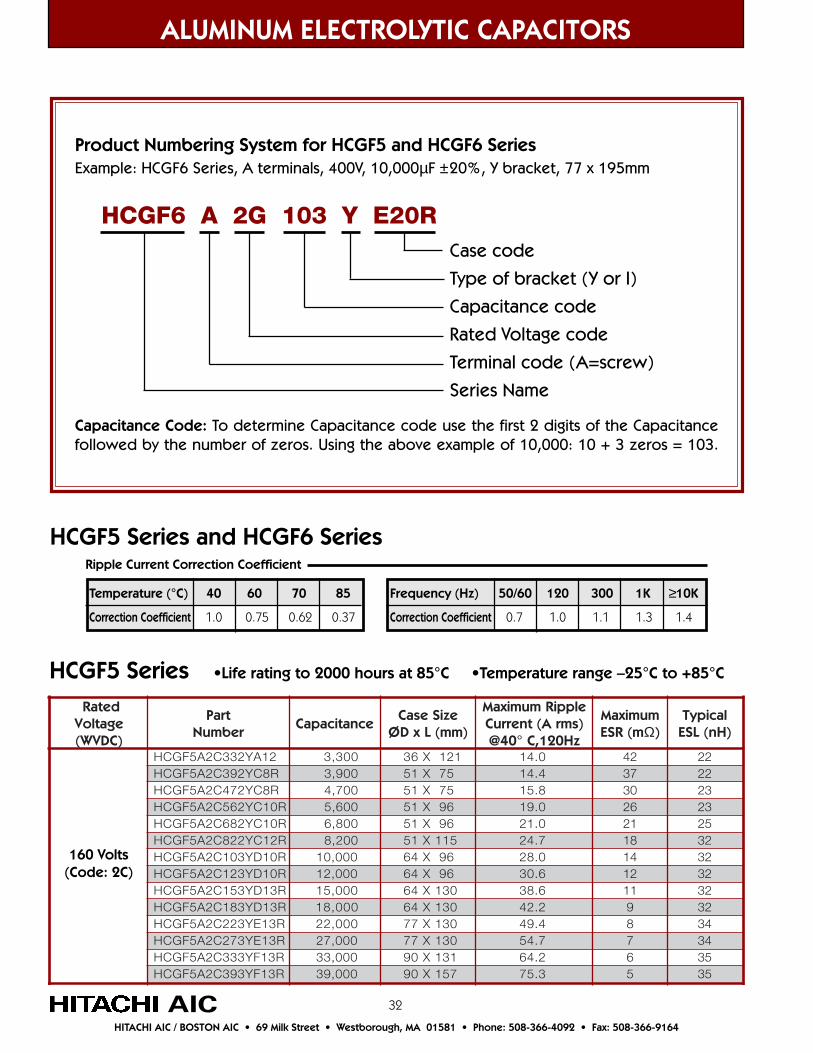
Product Numbering System for HCGF5 and HCGF6 SeriesExample: HCGF6 Series, A terminals, 400V, 10,000µF ±20%, Y bracket, 77 x 195mm
Case code
Type of bracket (Y or I)
Capacitance code
Rated Voltage code
Terminal code (A=screw)
Series Name
HCGF6 A 2G 103 Y E20R
Capacitance Code: To determine Capacitance code use the first 2 digits of the Capacitancefollowed by the number of zeros. Using the above example of 10,000: 10 + 3 zeros = 103.
160 Volts(Code: 2C)
Temperature (°C) 40 60 70 85
Correction Coefficient 1.0 0.75 0.62 0.37
Frequency (Hz) 50/60 120 300 1K ≥10K
Correction Coefficient 0.7 1.0 1.1 1.3 1.4
Ripple Current Correction Coefficient
HITACHI AIC / BOSTON AIC • 69 Milk Street • Westborough, MA 01581 • Phone: 508-366-4092 • Fax: 508-366-9164
HCGF5 Series and HCGF6 Series
detaRegatloV)CDVW(
traPrebmuN
ecnaticapaCeziSesaC
)mm(LxDØ
elppiRmumixaMtnerruC A( smr )
zH021,C°04@
mumixaMm(RSE Ω)
lacipyT)Hn(LSE
GCH 233C2A5F Y 21A 3,3 00 X63 121 0.41 24 22GCH 293C2A5F Y R8C 9,3 00 15 X 57 4.41 73 22GCH 274C2A5F Y R8C 7,4 00 15 X 57 8.51 03 32GCH 265C2A5F Y R01C 6,5 00 X15 69 0.91 62 32GCH 286C2A5F Y R01C 8,6 00 X15 69 0.12 12 52GCH 228C2A5F Y R21C 2,8 00 15 1X 51 7.42 81 23GCH 301C2A5F Y R01D 01 000, X46 69 0.82 41 23GCH 321C2A5F Y R01D 21 000, 46 X 69 6.03 21 23GCH 351C2A5F Y R31D 0,51 00 46 X 031 6.83 11 23GCH 381C2A5F Y R31D 0,81 00 46 X 031 2.24 9 23GCH 322C2A5F Y R31E 22 000, 77 1X 03 4.94 8 43GCH 372C2A5F Y R31E 72 000, 77 X 031 7.45 7 43GCH 333C2A5F Y R31F 33 000, 09 1X 13 2.46 6 53GCH 393C2A5F Y R31F 39 000, 09 1X 75 3.57 5 53
33
ALUMINUM ELECTROLYTIC CAPACITORS
AIC
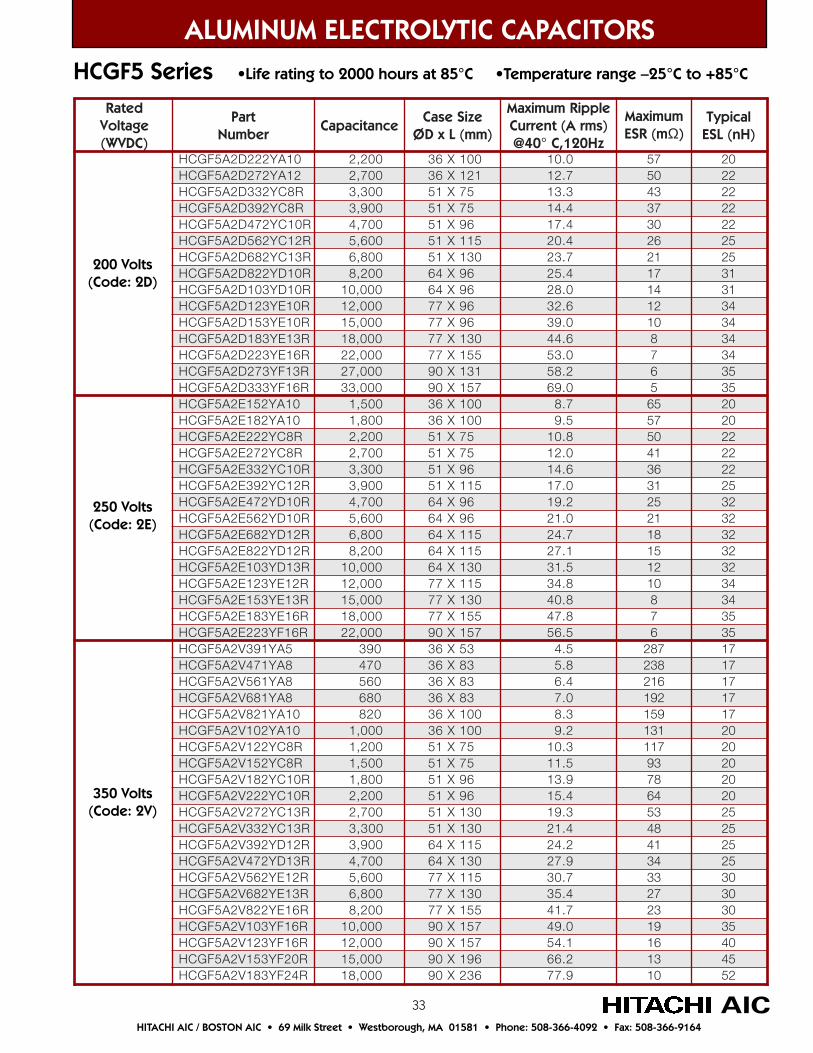
HCGF5 Series •Life rating to 2000 hours at 85°C •Temperature range –25°C to +85°C
detaRegatloV)CDVW(
traPrebmuN
ecnaticapaCeziSesaC
)mm(LxDØ
elppiRmumixaMtnerruC A( smr )
zH021,C°04@
mumixaMm(RSE Ω)
lacipyT)Hn(LSE
5FGCH A Y222D2 01A 002,2 X63 001 0.01 75 02GCH 21AY272D2A5F 007,2 X63 121 7.21 05 22GCH 233D2A5F Y R8C 3,3 00 15 X 57 3.31 34 22GCH 293D2A5F Y R8C 9,3 00 15 X 57 4.41 73 22GCH 274D2A5F Y R01C 7,4 00 X15 69 4.71 03 22GCH 265D2A5F Y R21C 6,5 00 15 1X 51 4.02 62 52GCH 286D2A5F Y R31C 8,6 00 15 X 031 7.32 12 52GCH 228D2A5F Y R01D 2,8 00 46 X 69 4.52 71 13GCH 301D2A5F R01DY 1 000,0 46 X 69 0.82 41 13GCH 321D2A5F Y R01E 21 000, 77 X 69 6.23 21 43GCH 351D2A5F Y R01E 0,51 00 77 69X 0.93 01 43GCH 381D2A5F Y R31E 81 000, 77 X 031 6.44 8 43GCH 322D2A5F Y R61E 22 000, 77 X 551 0.35 7 43GCH 372D2A5F Y R31F 27 000, 09 1X 13 2.85 6 53GCH D2A5F 333 Y R61F 000,33 09 X 751 0.96 5 53GCH 251E2A5F Y 01A 5,1 00 63 X 001 7.8 56 02GCH 281E2A5F Y 01A 008,1 63 X 001 5.9 75 02GCH 222E2A5F Y R8C 2,2 00 15 X 57 8.01 05 22GCH 272E2A5F Y R8C 7,2 00 15 X 57 0.21 14 22GCH 233E2A5F Y R01C 3,3 00 15 69X 6.41 63 22GCH 293E2A5F Y R21C 9,3 00 15 511X 0.71 13 52GCH 274E2A5F Y R01D 7,4 00 46 X 69 2.91 52 23GCH 265E2A5F Y R01D 6,5 00 46 X 69 0.12 12 23GCH 286E2A5F Y R21D 8,6 00 46 X 511 7.42 81 23GCH 228E2A5F Y R21D 002,8 46 X 511 1.72 51 23GCH 301E2A5F Y R31D 01 000, 46 X 031 5.13 21 23GCH 321E2A5F Y R21E 21 000, 77 X 511 8.43 01 43GCH 351E2A5F Y R31E 51 000, 77 X 031 8.04 8 43GCH 381E2A5F Y R61E 81 000, 77 X 551 8.74 7 53GCH 322E2A5F Y R61F 000,22 751X09 5.65 6 53GCH 193V2A5F Y 5A 93 0 63 X 35 5.4 782 71GCH 174V2A5F Y 8A 74 0 63 X 38 8.5 832 71GCH 8AY165V2A5F 065 X63 83 4.6 612 71GCH 186V2A5F Y 8A 86 0 X63 38 0.7 291 71GCH 128V2A5F Y 01A 28 0 X63 001 3.8 951 71GCH 201V2A5F Y 01A 000,1 1X63 00 2.9 131 02GCH 221V2A5F Y R8C 002,1 X15 57 3.01 711 02GCH 251V2A5F Y R8C 5,1 00 X15 57 5.11 39 02GCH 281V2A5F Y R01C 8,1 00 15 X 69 9.31 87 02GCH 222V2A5F Y R01C 2,2 00 15 X 69 4.51 46 02GCH 272V2A5F Y R31C 7,2 00 15 1X 03 3.91 35 52GCH 233V2A5F Y R31C 3,3 00 15 X 031 4.12 84 52GCH 293V2A5F Y R21D 9,3 00 46 X 511 2.42 14 52GCH 274V2A5F Y R31D 7,4 00 46 X 031 9.72 43 52GCH 265V2A5F Y R21E 6,5 00 77 X 511 7.03 33 03GCH 286V2A5F Y R31E 8,6 00 77 X 031 4.53 72 03GCH 228V2A5F Y R61E 002,8 77 X 551 7.14 32 03GCH 301V2A5F Y R61F 01 000, 09 X 751 0.94 91 53GCH 321V2A5F Y R61F 21 000, 09 X 751 1.45 61 04GCH 351V2A5F Y R02F 51 000, 09 X 691 2.66 31 54
R42FY381V2A5FGCH 000,81 632X09 9.77 01 25
200 Volts(Code: 2D)
250 Volts(Code: 2E)
350 Volts(Code: 2V)
HITACHI AIC / BOSTON AIC • 69 Milk Street • Westborough, MA 01581 • Phone: 508-366-4092 • Fax: 508-366-9164
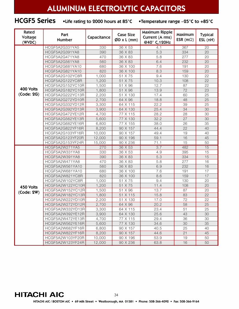
34
detaRegatloV)CDVW(
traPrebmuN
ecnaticapaCeziSesaC
)mm(LxDØ
elppiRmumixaMtnerruC A( smr )
@ 04 zH021,C°
mumixaMm(RSE Ω)
lacipyT)Hn(LSE
Y133G2A5FGCH 5A 33 0 35X63 1.4 763 02GCH 8AY193G2A5F 93 0 X63 38 3.5 433 02GCH 174G2A5F Y 8A 74 0 38X63 8.5 772 02GCH 165G2A5F Y 8A 65 0 63 X 38 4.6 232 02GCH 186G2A5F Y 01A 86 0 63 X 001 6.7 191 02GCH 128G2A5F Y 01A 28 0 63 001X 3.8 951 02GCH 201G2A5F Y R8C 0,1 00 15 X 57 4.9 031 22GCH 221G2A5F Y R8C 2,1 00 15 57X 3.01 801 22GCH 251G2A5F Y R01C 5,1 00 15 X 69 7.21 78 22GCH 281G2A5F Y R01C 8,1 00 15 X 69 9.31 27 32GCH 222G2A5F Y R31C 2,2 00 15 31X 0 4.71 06 52GCH 272G2A5F Y R01D 07,2 0 46 X 69 8.81 84 52GCH 233G2A5F Y R21D 03,3 0 46 511X 2.22 93 52GCH 293G2A5F Y R31D 09,3 0 46 031X 4.52 43 03GCH 274G2A5F Y R21E 7,4 00 77 X 511 2.82 82 03GCH 265G2A5F Y R31E 6,5 00 77 X 031 2.23 72 03GCH 286G2A5F Y R61E 8,6 00 77 X 551 0.83 62 53GCH 228G2A5F Y R61F 2,8 00 09 X 751 4.44 22 04GCH 301G2A5F Y R61F 0,01 00 09 X 751 4.94 91 04GCH 321G2A5F Y R02F 21 000, 09 X 1 69 1.95 61 54GCH 351G2A5F Y R42F 0,51 00 09 X 632 1.17 51 05GCH 172W2A5F Y 5A 72 0 63 X 35 7.3 284 51GCH 133W2A5F Y 8A 33 0 63 X 35 9.4 593 51GCH 193W2A5F Y 8A 93 0 63 X 38 3.5 433 51GCH 174W2A5F Y 8A 74 0 63 X 38 8.5 772 61GCH 165W2A5F Y 01A 65 0 63 X 38 9.6 232 61GCH 186W2A5F Y 01A 86 0 63 X 001 6.7 191 71GCH 128W2A5F Y R8C 28 0 63 X 001 6.8 951 71GCH 201W2A5F Y R8C 0,1 00 15 X 57 4.9 031 02GCH 221W2A5F Y R01C 2,1 00 57X15 4.11 801 02GCH 251W2A5F Y R21C 5,1 00 15 X 69 7.31 78 02GCH 281W2A5F Y R31C 8,1 00 15 X 511 8.51 38 22GCH R01DY222W2A5F 2,2 00 15 X 031 0.71 27 22GCH 272W2A5F Y R21D 07,2 0 46 X 69 2.02 85 52GCH 233W2A5F Y R31D 03,3 0 46 511X 4.32 15 52GCH 293W2A5F Y R21E 09,3 0 46 031X 6.52 34 03GCH 274W2A5F Y R31E 7,4 00 77 X 511 4.92 63 03GCH 265W2A5F Y R61E 6,5 00 77 X 031 6.43 03 53GCH 286W2A5F Y R61F 8,6 00 09 X 751 5.04 52 04GCH 228W2A5F Y R61F 2,8 00 09 751X 6.44 12 54GCH 301W2A5F Y R02F 0,01 00 09 X 691 9.35 91 05GCH 321W2A5F Y R42F 0,21 00 09 X 632 8.36 61 05
ALUMINUM ELECTROLYTIC CAPACITORS
AIC
HCGF5 Series •Life rating to 2000 hours at 85°C •Temperature range –25°C to +85°C
400 Volts(Code: 2G)
450 Volts(Code: 2W)
HITACHI AIC / BOSTON AIC • 69 Milk Street • Westborough, MA 01581 • Phone: 508-366-4092 • Fax: 508-366-9164
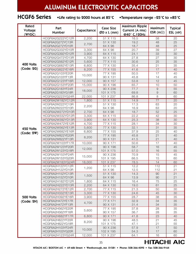
35
ALUMINUM ELECTROLYTIC CAPACITORSHCGF6 Series •Life rating to 2000 hours at 85°C •Temperature range –25°C to +85°C
AIC
detaRegatloV)CDVW(
traPrebmuN
ecnaticapaCeziSesaC
)mm(LxDØ
elppiRmumixaMA(tnerruC smr )
@ 04 zH021,C°
mumixaMm(RSE Ω)
lacipyT)Hn(LSE
FGCH A6 Y222G2 R21C 002,2 15 X 511 5.61 85 02GCH R31CY272G2A6F
R01DY272G2A6FGCH007,2
15 X 03169X46
2.917.81
8484
5252
GCH 233G2A6F Y R01D 3,3 00 46 X 69 7.02 93 72GCH 293G2A6F Y R21D 9,3 00 46 X 511 1.42 33 03GCH 274G2A6F Y R31D 7,4 00 46 X 031 8.72 72 03GCH 265G2A6F Y R21E 6,5 00 77 1X 51 6.03 52 53GCH 286G2A6F Y R31E 8,6 00 77 X 031 4.53 12 53GCH 228G2A6F Y R61E 2,8 00 77 551X 6.14 71 04GCH 301G2A6F R02EY
R31FY301G2A6FGCH1 000,0
77 X 591131X09
5.058.54
7141
0454
GCH 321G2A6F Y R61F 21 000, 09 X 751 8.35 21 54GCH 351G2A6F Y R02F 0,51 00 09 X 1 69 7.56 01 05GCH 381G2A6F R42FY
R81GY381G2A6FGCH81 000,
09 X 632571X101
7.778.96
99
5506
GCH 322G2A6F Y R42G 22 000, 101 X 732 8.68 8 06GCH 281W2A6F Y R21C 008,1 15 511X 9.41 77 02GCH R31CY222W2A6F
R01DY222W2A6FGCH2,2 00
15 X 03169X46
3.719.61
3636
0202
GCH 272W2A6F Y R01D 7,2 00 46 X 69 7.81 25 52GCH 233W2A6F Y R21D 3,3 00 46 X 511 2.22 24 03GCH 293W2A6F Y R31D 9,3 00 46 X 031 3.52 83 03GCH 274W2A6F Y R21E 7,4 00 77 X 511 1.82 43 03GCH 265W2A6F Y R31E 6,5 00 77 X 031 1.23 13 53GCH 286W2A6F Y R61E 8,6 00 77 1X 55 9.73 52 04GCH R02EY228W2A6F
R31FY228W2A6FGCH2,8 00
77 X 591131X09
8.545.14
1212
0404
GCH 301W2A6F Y R71F 0,01 00 09 X 171 6.05 71 04GCH 321W2A6F Y R02F
R81GY321W2A6FGCH0,21 00
09 X 691571X101
7.850.75
6161
5455
GCH 351W2A6F R42FYR02GY351W2A6FGCH
0,51 0009 X 632
591X1019.075.66
5151
5406
GCH 381W2A6F Y R42G 81 000, 101 X 732 5.87 41 06GCH 221H2A6F R21CY
R01DY221H2A6FGCH002,1
15 X 51169X46
2.215.21
211211
1212
GCH 251H2A6F R31CYR01DY251H2A6FGCH
005,115 X 031
69X463.419.31
0909
1212
GCH 281H2A6F Y R21D 08,1 0 46 X 511 4.61 57 52GCH 222H2A6F Y R31D 2,2 00 031X46 0.91 16 52GCH 272H2A6F Y R21E 07,2 0 77 511X 3.12 05 03GCH 233H2A6F Y R31E 03,3 0 77 X 031 6.42 54 03GCH R61EY293H2A6F 09,3 0 77 551X 7.82 83 53GCH 274H2A6F R71EY
R31FY274H2A6FGCH07,4 0
77 X 171131X09
9.234.13
4343
5353
GCH 265H2A6F R02EYR61FY265H2A6FGCH
06,5 077 X 591
751X098.737.63
8282
5353
GCH 286H2A6F Y R71F 8,6 00 09 1X 17 8.14 32 04GCH 228H2A6F R02FY
2A6FGCH H R81GY2282,8 00
09 X 691571X101
5.841.74
1212
5455
GCH 301H2A6F R42FYR02GY301H2A6FGCH
0,01 0009 X 632
591X2019.753.45
7171
0506
GCH 321H2A6F Y R42G 0,21 00 101 X 732 1.46 61 06
450 Volts(Code: 2W)
400 Volts(Code: 2G)
500 Volts(Code: 2H)
HITACHI AIC / BOSTON AIC • 69 Milk Street • Westborough, MA 01581 • Phone: 508-366-4092 • Fax: 508-366-9164

36
detaRegatloV)CDVW(
traPrebmuN
ecnaticapaCeziSesaC
)mm(LxDØ
elppiRmumixaMtnerruC A( smr )
@ 58 zH021,C°
mumixaMm(RSE Ω)
lacipyT)Hn(LSE
R8CY221V2AXF 2,1 00 15 X 57 5.5 56 52Y251V2AXF R8C 5,1 00 15 X 57 1.6 35 52Y281V2AXF R01C 8,1 00 X15 69 4.7 44 52Y222V2AXF R01C 2,2 00 X15 69 2.8 82 52Y272V2AXF R31C 7,2 00 15 1X 03 2.01 72 52Y233V2AXF R31C 003,3 15 031X 3.11 12 03Y293V2AXF R21D 9,3 00 46 X 511 8.21 81 03Y274V2AXF R31D 7,4 00 46 X 031 8.41 61 03
R61DY265V2AXFR21EY265V2AXF
6,5 0046 X 551
511X773.713.61
4141
0404
R02DY286V2AXFR31EY286V2AXF
008,646 1X 59
031X771.128.81
2141
0505
Y228V2AXF R61E 002,8 77 X 551 1.22 21 05Y301V2AXF R61F 01 000, 09 1X 75 9.52 01 05Y321V2AXF R61F 000,21 09 1X 75 4.82 8 05
R02FY351V2AXF 000,51 691X09 6.43 6 06R42FY381V2AXF 000,81 632X09 1.14 5 07
ALUMINUM ELECTROLYTIC CAPACITORS
AIC
FXA Series •Life rating to 5000 hours at 85°C •Temperature range –40°C to +85°C
350 Volts(Code: 2V)
Product Numbering System for FXA, FXR, FX2, GXA, GXR, GX2, GXH and HXA SeriesExample: FXA Series, 400V, 4,700µF ±20%, Y bracket, 64 x 155mm
Case code
Type of bracket (Y or I)
Capacitance code
Rated Voltage code
Series Name
FXA 2G 472 Y D16R
Capacitance Code: To determine Capacitance code use the first 2 digits of the Capacitancefollowed by the number of zeros. Using the above example of 4,700: 47 + 2 zeros = 472.
Frequency (Hz) 50/60 120 300 1K ≥10K
Correction Coefficient 0.7 1.0 1.1 1.3 1.4
Ripple Current Correction Coefficient
Temperature (°C) 40 60 85
Correction Coefficient 1.89 1.67 1.00
FXA Series, FXR Series and FX2 Series
HITACHI AIC / BOSTON AIC • 69 Milk Street • Westborough, MA 01581 • Phone: 508-366-4092 • Fax: 508-366-9164

37
ALUMINUM ELECTROLYTIC CAPACITORS
AIC
detaRegatloV)CDVW(
traPrebmuN
ecnaticapaCeziSesaC
)mm(LxDØ
elppiRmumixaMtnerruC A( smr )
@ 58 zH021,C°
mumixaMm(RSE Ω)
lacipyT)Hn(LSE
R8CY201G2AXF 000,1 57X15 0.5 87 02R8CY221G2AXF 002,1 57X15 5.5 96 02
R01CY251G2AXF 005,1 69X15 7.6 05 52R01CY281G2AXF 008,1 69X15 4.7 04 52R31CY222G2AXF 002,2 031X15 2.9 82 52R01DY272G2AXF 007,2 69X46 9.9 42 52R21DY233G2AXF 003,3 511X46 8.11 12 03R31DY293G2AXF 009,3 031X46 5.31 81 03R61DY274G2AXFR31EY274G2AXF
007,4551X46031X77
9.519.41
6141
0303
R02DY265G2AXFR31EY265G2AXF
006,5591X46031X77
1.910.71
4121
0404
R61EY286G2AXF 008,6 551X77 2.02 41 05R61FY228G2AXF 002,8 751X09 5.32 21 05R61FY301G2AXF 000,01 751X09 9.52 01 05R02FY321G2AXF 000,21 691X09 0.13 8 05R42FY351G2AXF 000,51 632X09 5.73 6 06R8CY201W2AXF 000,1 57X15 0.5 59 02
R01CY221W2AXF 002,1 69X15 0.6 07 02R21CY251W2AXF 005,1 511X15 2.7 55 52R31CY281W2AXF 008,1 031X15 3.8 64 52R01DY222W2AXF 002,2 69X46 0.9 24 53R21DY272W2AXF 007,2 511X46 7.01 83 53R31DY233W2AXF 003,3 031X46 4.21 03 53
R61DY293W2AXFR21EY293W2AXF
009,3551X46511X77
4.416.31
7242
5353
R02DY274W2AXFR31EY274W2AXF
007,4591X46031X77
5.716.51
0222
5353
R61EY265W2AXF 006,5 551X77 3.81 02 05R61FY286W2AXF 008,6 751X09 4.12 81 05R61FY228W2AXF 002,8 751X09 5.32 51 05R02FY301W2AXF 000,01 691X09 3.82 21 05R42FY321W2AXF 000,21 632X09 6.33 9 05
400 Volts(Code: 2G)
450 Volts(Code: 2W)
FXA Series
HITACHI AIC / BOSTON AIC • 69 Milk Street • Westborough, MA 01581 • Phone: 508-366-4092 • Fax: 508-366-9164
•Life rating to 5000 hours at 85°C•Temperature range –40°C to +85°C

38AIC
ALUMINUM ELECTROLYTIC CAPACITORS
HITACHI AIC / BOSTON AIC • 69 Milk Street • Westborough, MA 01581 • Phone: 508-366-4092 • Fax: 508-366-9164
detaRegatloV)CDVW(
traPrebmuN
ecnaticapaCeziSesaC
)mm(LxDØ
elppiRmumixaMtnerruC A( smr )
@8 zH021,C°5
mumixaMm(RSE Ω)
lacipyT)Hn(LSE
T21EY265V2RXFT11FY265V2RXF
6,5 0077 X 121
601X096.123.22
2131
5405
T31EY286V2RXFT21FY286V2RXF
8,6 0077 X 731
121X090.522.62
0111
5405
T61EY228V2RXFT41FY228V2RXF
2,8 0077 X 161
731X093.921.03
0121
0505
T61FY301V2RXF 0,01 00 09 X 161 7.53 9 05T61FY321V2RXF 0,21 00 09 X 161 1.93 8 05T31EY274G2RXFT11FY274G2RXF
7,4 0077 731X
601X098.025.02
4151
5304
T41EY265G2RXFT21FY265G2RXF
6,5 0077 X 731
121X097.228.32
2131
0505
T61EY286G2RXFT41FY286G2RXF
8,6 0077 161X
731X096.624.72
0111
0505
T61FY228G2RXF 2,8 00 09 X 161 2.23 01 05T61FY301G2RXF 0,01 00 09 X 161 7.53 9 05T21EY293W2RXFT11FY293W2RXF
9,3 0077 X 121
601X090.816.81
5272
0454
T31EY274W2RXFT21FY274W2RXF
7,4 0077 X 731
121X098.028.12
8102
0505
T61EY265W2RXFT41FY265W2RXF
6,5 0077 1X 16
731X092.429.42
5171
0505
T61FY286W2RXF 8,6 00 161X09 4.92 41 05T61FY228W2RXF 2,8 00 09 X 161 2.23 01 05T81FY301W2RXF 0,01 00 09 X 871 9.63 9 05T21EY272H2RXF 007,2 121X77 0.51 33 02T61EY233H2RXFT11FY233H2RXF
003,3161X77601X09
5.817.41
0313
0202
T61FY293H2RXFT21FY293H2RXF
009,3161X77121X09
2.020.91
5262
0202
T41FY274H2RXF 007,4 731X09 8.12 02 02T61FY265H2RXF 006,5 161X09 3.52 81 03T81FY286H2RXF 008,6 871X09 0.92 61 03
400 Volts(Code: 2G)
350 Volts(Code: 2V)
450 Volts(Code: 2W)
500 Volts(Code: 2H)
FXR Series •Life rating to 5000 hours at 85°C •Temperature range –40°C to +85°C
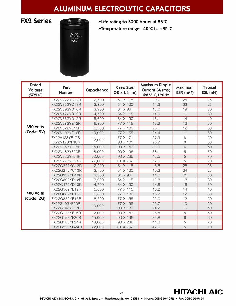
39
detaRegatloV)CDVW(
traPrebmuN
ecnaticapaCeziSesaC
)mm(LxDØ
elppiRmumixaMtnerruC A( smr )
@ 58 zH021,C°
mumixaM(RSE mΩ)
lacipyT)Hn(LSE
272V22XF Y R21C 07,2 0 15 X 511 7.9 52 52XF 33V22 2 R31CY 03,3 0 15 X 031 3.11 22 52XF 93V22 Y2 R01D 09,3 0 46 X 69 0.21 91 03XF 74V22 Y2 R21D 07,4 0 46 X 511 0.41 61 03XF 65V22 Y2 R31D 06,5 0 46 X 031 1.61 41 04XF 86V22 Y2 R21E 08,6 0 77 511X 9.71 21 05XF 28V22 Y2 R31E 2,8 00 77 X 031 6.02 21 05XF 301V22 Y R61E 00,01 0 77 551X 4.42 11 05XF 321V22 Y R71E
R31FY321V22XF0,21 00
77 X 171131X09
9.727.62
88
0505
XF 351V22 Y R61F 0,51 00 09 X 751 9.13 6 06XF 381V22 Y R02F 0,81 00 09 X 691 1.83 5 07XF 322V22 Y R42F 00,22 0 09 X 632 5.54 5 07XF 72V22 Y3 R42G 00,72 0 101 X 732 0.25 5 07XF 222G22 Y R21C 02,2 0 15 511X 8.8 82 52XF 272G22 Y R31C 7,2 00 15 X 031 2.01 42 52XF 33G22 Y2 R01D 3,3 00 46 X 69 0.11 12 03XF 93G22 Y2 R21D 9,3 00 46 X 511 8.21 81 03XF 74G22 Y2 R31D 7,4 00 46 X 031 8.41 61 03XF 65G22 Y2 R21E 6,5 00 77 X 511 2.61 41 04XF 86G22 Y2 R31E 8,6 00 77 X 031 7.81 21 05XF 28G22 Y2 R61E 2,8 00 77 X 551 0.22 21 05XF 301G22 Y R02E
R31FY301G22XF00,01 0
77 X 591131X09
7.622.42
0101
0505
XF 321G22 Y R61F 00,21 0 09 X 751 5.82 8 05XF 351G22 Y R02F 00,51 0 09 1X 69 8.43 6 06XF 381G22 FY R42 00,81 0 09 X 632 2.14 5 07XF 322G22 Y R42G 00,22 0 101 X 732 0.74 5 07
ALUMINUM ELECTROLYTIC CAPACITORS
FX2 Series
HITACHI AIC / BOSTON AIC • 69 Milk Street • Westborough, MA 01581 • Phone: 508-366-4092 • Fax: 508-366-9164
AIC
•Life rating to 5000 hours at 85°C•Temperature range –40°C to +85°C
400 Volts(Code: 2G)
350 Volts(Code: 2V)
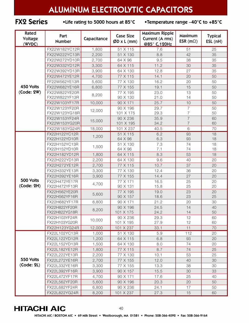
40
detaRegatloV)CDVW(
traPrebmuN
ecnaticapaCeziSesaC
)mm(LxDØ
elppiRmumixaMtnerruC A( smr )
@ 58 zH021,C°
mumixaMm(RSE Ω)
lacipyT)Hn(LSE
R21CY281W22XF 008,1 511X15 6.7 15 52R31CY222W22XF 002,2 031X15 8.8 24 53R01DY272W22XF 007,2 69X46 5.9 83 53R21DY233W22XF 003,3 511X46 2.11 03 53R31DY293W22XF 009,3 031X46 8.21 72 53R21EY274W22XF 007,4 511X77 1.41 02 05R31EY265W22FF 006,5 031X77 2.61 02 05R61EY286W22XF 008,6 551X77 1.91 51 05R02EY228W22XFR31FY228W22XF
002,8591X77031X09
0.320.12
3141
0505
R71FY301W22XF 000,01 171X09 7.52 01 05R02FY321W22XFR81GY321W22XF
000,21691X09571X101
7.923.92
77
0505
R42FY351W22XFR02GY351W22XF
000,51632X09591X101
9.532.43
77
0606
R42GY381W22XF 000,81 732X101 5.04 6 07R21CY221H22XFR01DY221H22XF
02,1 015 X 511
69X462.63.6
3939
8181
XF 51H22 2 R31CYR01DY251H22XF
05,1 0031X15
46 X 693.71.7
4747
8181
XF 81H22 Y2 R21D 08,1 0 46 X 511 3.8 35 81XF 22H22 Y2 R31D 02,2 0 46 X 031 6.9 04 02XF 72H22 Y2 R21E 07,2 0 77 X 511 7.01 73 02XF 33H22 Y2 R31E 03,3 0 77 031X 4.21 63 02XF 93H22 Y2 R61E 9,3 00 77 X 551 4.41 72 02XF 274H22 Y R71E
R31FY274H22XF07,4 0
77 171X131X09
5.618.51
5252
0202
XF 265H22 Y R02ER61FY265H22XF
6,5 0077 X 591
751X090.916.81
3232
0252
XF 286H22 Y R71F 8,6 00 09 X 171 2.12 02 03XF 228H22 Y R02F
R81GY228H22XF2,8 00
09 X 691571X101
5.422.42
4141
0405
XF 301H22 Y R42FR02GY301H22XF
00,01 009 X 632
591X1013.929.72
2121
0606
XF 21H22 Y3 R42G 00,21 0 101 X 732 1.33 11 07XF 201L22 Y R31C 00,1 0 15 031X 9.5 211 02XF 221L22 Y R21D 2,1 00 46 X 511 8.6 39 02XF 51L22 Y2 R31D 5,1 00 46 X 031 0.8 47 02XF 81L22 Y2 R21E 8,1 00 77 X 511 7.8 47 52XF 22L22 Y2 R31E 2,2 00 77 X 031 1.01 35 52XF 72L22 Y2 R61E 7,2 00 77 X 551 0.21 04 03XF 33L22 Y2 R61E 3,3 00 77 X 551 3.31 83 03XF 93L22 Y2 R61F 9,3 00 09 X 751 5.51 03 33XF 274L22 Y R71F 07,4 0 09 X 171 6.71 52 04XF 265L22 Y R02F 06,5 0 09 X 691 3.02 02 05XF 286L22 Y R42F 08,6 0 09 X 32 6 1.42 71 05XF 228L22 Y R42G 02,8 0 101 X 732 3.72 51 06
ALUMINUM ELECTROLYTIC CAPACITORSFX2 Series
AIC
500 Volts(Code: 2H)
550 Volts(Code: 2L)
HITACHI AIC / BOSTON AIC • 69 Milk Street • Westborough, MA 01581 • Phone: 508-366-4092 • Fax: 508-366-9164
•Life rating to 5000 hours at 85°C •Temperature range –40°C to +85°C
450 Volts(Code: 2W)
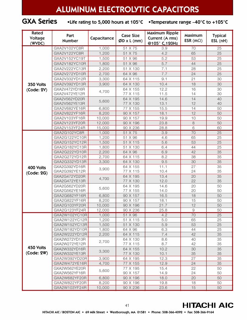
41
detaRegatloV)CDVW(
traPrebmuN
ecnaticapaCeziSesaC
)mm(LxDØ
elppiRmumixaMtnerruC A( smr )
zH021,C°501@
mumixaMm(RSE Ω)
lacipyT)Hn(LSE
Y201V2AXG R8C 0,1 00 15 X 57 9.3 07 52221V2AXG R8CY 2,1 00 15 X 57 2.4 56 52
Y251V2AXG T91C 5,1 00 15 X 69 2.5 35 52Y281V2AXG R01C 8,1 00 15 X 69 7.5 44 52Y222V2AXG R31C 2,2 00 X15 031 1.7 82 52Y272V2AXG R01D 7,2 00 46 X 69 7.7 42 52Y233V2AXG R21D 3,3 00 46 X 511 1.9 12 03Y293V2AXG R31D 9,3 00 46 031X 4.01 81 03Y274V2AXG R61D
R21EY274V2AXG7,4 00
46 X 551511X77
2.215.11
6141
0303
Y265V2AXG R02DR31EY265V2AXG
6,5 0046 X 591
031X776.411.31
4121
0404
Y286V2AXG R61E 8,6 00 77 X 551 5.51 41 05Y228V2AXG R61F 2,8 00 09 X 751 1.81 21 05Y301V2AXG R61F 01 000, 09 X 751 9.91 01 05Y321V2AXG R02F 000,21 09 1X 69 8.32 8 05
351V2AXG Y R42F 51 000, 09 X 632 8.82 6 06Y201G2AXG R8C 0,1 00 15 X 57 9.3 07 52Y221G2AXG R01C ,1 2 00 15 X 69 6.4 56 52Y251G2AXG R21C 5,1 00 15 X 511 6.5 35 52Y281G2AXG R31C 8,1 00 15 X 031 4.6 44 52Y222G2AXG R01D 2,2 00 46 69X 9.6 24 53Y272G2AXG R21D 7,2 00 46 511X 2.8 83 53Y233G2AXG R31D 3,3 00 46 X 031 5.9 03 53Y293G2AXG R61D
R21EY293G2AXG9,3 00
46 X 551511X77
1.114.01
7242
5353
Y274G2AXG R02DR31EY274G2AXG
7,4 0046 X 591
031X774.310.21
0222
5353
Y265G2AXG R02DR61EY265G2AXG
6,5 0046 X 591
551X776.410.41
0202
0505
Y286G2AXG R61F 008,6 09 X 751 5.61 81 05Y228G2AXG R61F 002,8 09 X 751 1.81 51 05Y301G2AXG R02F 01 000, 09 X 691 7.12 21 05Y321G2AXG R42F 21 000, 09 X 632 8.52 9 05Y201W2AXG R01C 1 000, 69X15 2.4 07 52Y221W2AXG R21C 02,1 0 15 511X 0.5 56 52Y251W2AXG R31C 05,1 0 15 X 031 9.5 35 52
281W2AXG R01DY 08,1 0 46 69X 3.6 44 52Y222W2AXG R21D 02,2 0 46 X 511 4.7 24 53Y272W2AXG R31D
R21EY272W2AXG07,2 0
46 X 031511X77
6.87.8
0424
5353
Y233W2AXG R61DR31EY233W2AXG
3,3 0046 1X 55
031X772.011.01
0353
5353
Y293W2AXG R02D 9,3 00 46 X 591 3.21 72 53Y274W2AXG R61E 7,4 00 77 X 551 9.21 42 53Y265W2AXG R02E
R61FY265W2AXG6,5 00
77 X 591751X09
4.519.41
2242
0505
Y286W2AXG R02F 8,6 00 09 1X 69 0.81 02 05Y228W2AXG R02F 2,8 00 09 1X 69 8.91 81 05Y301W2AXG R42F 0,01 00 09 X 632 6.32 51 05
ALUMINUM ELECTROLYTIC CAPACITORS
AIC
350 Volts(Code: 2V)
450 Volts(Code: 2W)
400 Volts(Code: 2G)
GXA Series •Life rating to 5,000 hours at 105°C •Temperature range –40°C to +105°C
HITACHI AIC / BOSTON AIC • 69 Milk Street • Westborough, MA 01581 • Phone: 508-366-4092 • Fax: 508-366-9164
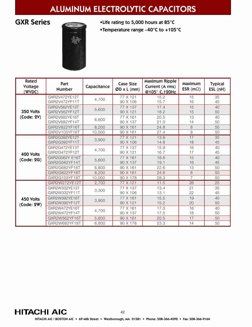
42
ALUMINUM ELECTROLYTIC CAPACITORS
AIC
detaRegatloV)CDVW(
traPrebmuN
ecnaticapaCeziSesaC
)mm(LxDØ
elppiRmumixaMtnerruC A( smr )
zH021,C°501@
mumixaMm(RSE Ω)
lacipyT)Hn(LSE
XG 274V2R Y T21ET11FY274V2RXG
7,4 0077 X 121
601X092.517.51
5161
5354
XG T31EY265V2RT21FY265V2RXG
6,5 0077 X 731
121X094.712.81
5151
0405
XG 286V2R Y T61ET41FY286V2RXG
8,6 0077 X 161
731X095.020.12
3141
0405
XG 228V2R Y T61F 2,8 00 09 X 161 8.42 8 05XG 301V2R Y T61F 0,01 00 09 X 161 4.72 8 05
Y293G2RXG T21ET11FY293G2RXG
9,3 0077 121X
601X098.318.41
7181
5354
XG 274G2R Y T31ET21FY274G2RXG
7,4 0077 X 731
121X099.517.61
6171
0454
XG 265G2R Y T61ET41FY265G2RXG
6,5 0077 161X
731X096.811.91
5161
0454
XG 286G2R Y T61F 8,6 00 09 X 161 6.22 31 05XG 228G2R Y T61F 2,8 00 09 X 161 8.42 8 05XG 301G2R Y T81F 0,01 00 09 X 871 3.82 7 05XG 272W2R Y T21E 7,2 00 77 X 121 5.11 62 52XG 233W2R T31EY
T11FY233W2RXG3,3 00
77 X 731601X09
4.311.31
1222
5354
XG 293W2R Y T61ET21FY293W2RXG
9,3 0077 1X 16
121X095.512.51
9102
0405
274W2RXG Y T61ET41FY274W2RXG
007,477 X 161
731X090.715.71
6181
0405
XG 265W2R Y T61F 6,5 00 09 X 161 5.02 71 05XG 286W2R Y T81F 8,6 00 09 X 871 3.32 41 05
GXR Series
350 Volts(Code: 2V)
450 Volts(Code: 2W)
400 Volts(Code: 2G)
HITACHI AIC / BOSTON AIC • 69 Milk Street • Westborough, MA 01581 • Phone: 508-366-4092 • Fax: 508-366-9164
•Life rating to 5,000 hours at 85°C•Temperature range –40°C to +105°C
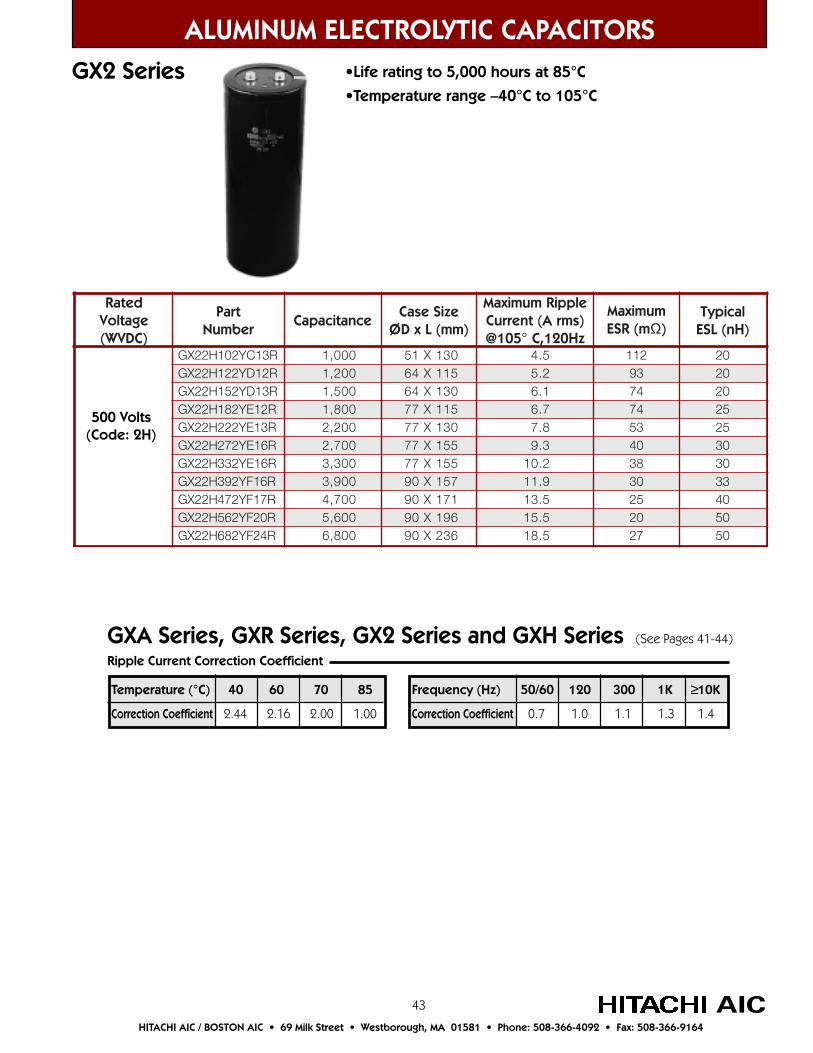
43
ALUMINUM ELECTROLYTIC CAPACITORSGX2 Series
AICHITACHI AIC / BOSTON AIC • 69 Milk Street • Westborough, MA 01581 • Phone: 508-366-4092 • Fax: 508-366-9164
500 Volts(Code: 2H)
detaRegatloV)CDVW(
traPrebmuN
ecnaticapaCeziSesaC
)mm(LxDØ
elppiRmumixaMtnerruC A( smr )
zH021,C°501@
mumixaMm(RSE Ω)
lacipyT)Hn(LSE
XG 201H22 Y R31C 000,1 031X15 5.4 211 02R21DY221H22XG 002,1 511X46 2.5 39 02
2XG R31DY251H2 5,1 00 031X46 1.6 47 02R21EY281H22XG 008,1 511X77 7.6 47 52
2XG 222H2 Y R31E 2,2 00 031X77 8.7 35 52R61EY272H22XG 007,2 551X77 3.9 04 03
2XG 233H2 Y R61E 3,3 00 551X77 2.01 83 032XG 293H2 Y R61F 9,3 00 751X09 9.11 03 33
H22XG 74 Y2 R71F 7,4 00 171X09 5.31 52 04R02FY265H22XG 006,5 691X09 5.51 02 05
2XG 286H2 Y R42F 8,6 00 632X09 5.81 72 05
•Life rating to 5,000 hours at 85°C•Temperature range –40°C to 105°C
Temperature (°C) 40 60 70 85
Correction Coefficient 2.44 2.16 2.00 1.00
Frequency (Hz) 50/60 120 300 1K ≥10K
Correction Coefficient 0.7 1.0 1.1 1.3 1.4
Ripple Current Correction Coefficient
GXA Series, GXR Series, GX2 Series and GXH Series (See Pages 41-44)
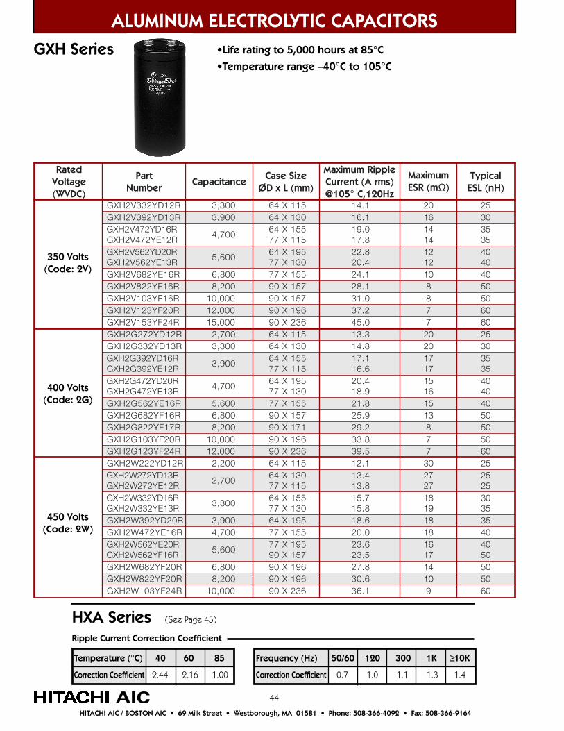
44
ALUMINUM ELECTROLYTIC CAPACITORSGXH Series
350 Volts(Code: 2V)
450 Volts(Code: 2W)
400 Volts(Code: 2G)
AICHITACHI AIC / BOSTON AIC • 69 Milk Street • Westborough, MA 01581 • Phone: 508-366-4092 • Fax: 508-366-9164
Frequency (Hz) 50/60 120 300 1K ≥10K
Correction Coefficient 0.7 1.0 1.1 1.3 1.4
Ripple Current Correction Coefficient
Temperature (°C) 40 60 85
Correction Coefficient 2.44 2.16 1.00
HXA Series (See Page 45)
detaRegatloV)CDVW(
traPrebmuN
ecnaticapaCeziSesaC
)mm(LxDØ
elppiRmumixaMtnerruC )smrA(
zH021,C°501@
mumixaMm(RSE Ω)
lacipyT)Hn(LSE
Y233V2HXG R21D 3,3 00 46 X 511 1.41 02 52XG R31DY293V2H 9,3 00 46 X 031 1.61 61 03XG 274V2H Y R61D
R21EY274V2HXG7,4 00
46 X 551511X77
0.918.71
4141
5353
XG R02DY265V2HR31EY265V2HXG
6,5 0046 X 591
031X778.224.02
2121
0404
XG 286V2H Y R61E 8,6 00 77 X 551 1.42 01 04XG 228V2H Y R61F 2,8 00 09 751X 1.82 8 05XG 301V2H Y R61F 0,01 00 09 X 751 0.13 8 05XG 321V2H Y R02F 0,21 00 09 691X 2.73 7 06XG 351V2H Y R42F 0,51 00 09 X 632 0.54 7 06XG 272G2H Y R21D 7,2 00 46 X 511 3.31 02 52XG 233G2H Y R31D 3,3 00 46 X 031 8.41 02 03XG 293G2H Y R61D
R21EY293G2HXG9,3 00
46 X 551511X77
1.716.61
7171
5353
XG 274G2H Y R02DR31EY274G2HXG
7,4 0046 X 591
031X774.029.81
5161
0404
XG 265G2H Y R61E 6,5 00 77 1X 55 8.12 51 04286G2HXG Y R61F 008,6 09 X 751 9.52 31 05
XG 228G2H Y R71F 002,8 09 X 171 2.92 8 05XG 301G2H Y R02F 0,01 00 09 X 691 8.33 7 05XG 321G2H Y R42F 0,21 00 09 X 632 5.93 7 06XG 222W2H Y R21D 2,2 00 46 X 511 1.21 03 52XG 272W2H Y R31D
R21EY272W2HXG7,2 00
46 X 031511X77
4.318.31
7272
5252
XG 233W2H Y R61DR31EY233W2HXG
3,3 0046 X 51 5
031X777.518.51
8191
0353
XG 293W2H DY R02 9,3 00 46 X 591 6.81 81 53XG 274W2H Y R61E 7,4 00 77 X 551 0.02 81 04XG 265W2H Y R02E
R61FY265W2HXG6,5 00
77 X 591751X09
6.325.32
6171
0405
XG 286W2H Y R02F 8,6 00 09 X 691 8.72 41 05XG 228W2H Y R02F 2,8 00 09 X 691 6.03 01 05XG 301W2H Y R42F 0,01 00 09 X 632 1.63 9 06
•Life rating to 5,000 hours at 85°C•Temperature range –40°C to 105°C
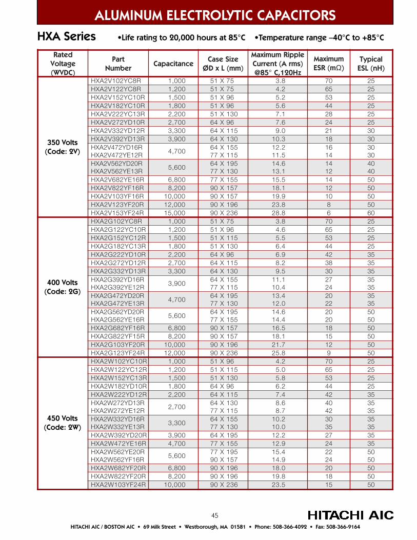
45
350 Volts(Code: 2V)
450 Volts(Code: 2W)
400 Volts(Code: 2G)
HXA Series •Life rating to 20,000 hours at 85°C •Temperature range –40°C to +85°C
ALUMINUM ELECTROLYTIC CAPACITORS
AICHITACHI AIC / BOSTON AIC • 69 Milk Street • Westborough, MA 01581 • Phone: 508-366-4092 • Fax: 508-366-9164
detaRegatloV)CDVW(
traPrebmuN
ecnaticapaCeziSesaC
)mm(LxDØ
elppiRmumixaMtnerruC A( smr )
zH021,C°58@
mumixaMm(RSE Ω)
lacipyT)Hn(LSE
Y201V2AXH R8C 0,1 00 15 X 57 8.3 07 52H 221V2AX R8CY 2,1 00 15 X 57 2.4 56 52
Y251V2AXH R01C 5,1 00 15 X 69 2.5 35 52Y281V2AXH R01C 8,1 00 15 X 69 6.5 44 52Y222V2AXH R31C 2,2 00 X15 031 1.7 82 52Y272V2AXH R01D 7,2 00 46 X 69 6.7 42 52Y233V2AXH R21D 3,3 00 46 X 511 0.9 12 03Y293V2AXH R31D 9,3 00 46 031X 3.01 81 03Y274V2AXH R61D
R21EY274V2AXH7,4 00
46 X 551511X77
2.215.11
6141
0303
Y265V2AXH R02DR31EY265V2AXH
6,5 0046 X 591
031X776.411.31
4121
0404
Y286V2AXH R61E 8,6 00 77 X 551 5.51 41 05Y228V2AXH R61F 2,8 00 09 X 751 1.81 21 05Y301V2AXH R61F 01 000, 09 X 751 9.91 01 05Y321V2AXH R02F 000,21 09 1X 69 8.32 8 05
351V2AXH Y R42F 51 000, 09 X 632 8.82 6 06Y201G2AXH R8C 0,1 00 15 X 57 8.3 07 52Y221G2AXH R01C ,1 2 00 15 X 69 6.4 56 52Y251G2AXH R21C 5,1 00 15 X 511 5.5 35 52Y281G2AXH R31C 8,1 00 15 X 031 4.6 44 52Y222G2AXH R01D 2,2 00 46 69X 9.6 24 53Y272G2AXH R21D 7,2 00 46 511X 2.8 83 53Y233G2AXH R31D 3,3 00 46 X 031 5.9 03 53Y293G2AXH R61D
R21EY293G2AXH9,3 00
46 X 551511X77
1.114.01
7242
5353
Y274G2AXH R02DR31EY274G2AXH
7,4 0046 X 591
031X774.310.21
0222
5353
Y265G2AXH R02DR61EY265G2AXH
6,5 0046 X 591
551X776.414.41
0202
0505
Y286G2AXH R61F 008,6 09 X 751 5.61 81 05Y228G2AXH R51F 002,8 09 X 751 1.81 51 05Y301G2AXH R02F 01 000, 09 X 691 7.12 21 05Y321G2AXH R42F 21 000, 09 X 632 8.52 9 05Y201W2AXH R01C 1 000, 69X15 2.4 07 52Y221W2AXH R21C 02,1 0 15 511X 0.5 56 52Y251W2AXH R31C 05,1 0 15 X 031 8.5 35 52
H 281W2AX R01DY 08,1 0 46 69X 2.6 44 52Y222W2AXH R21D 02,2 0 46 X 511 4.7 24 53Y272W2AXH R31D
R21EY272W2AXH07,2 0
46 X 031511X77
6.87.8
0424
5353
233W2AXH R61DYAXH R31EY233W2
3,3 0046 1X 55
031X772.010.01
0353
5353
Y293W2AXH R02D 9,3 00 46 X 591 2.21 72 53Y274W2AXH R61E 7,4 00 77 X 551 9.21 42 53Y265W2AXH R02E
R61FY265W2AXH6,5 00
77 X 591751X09
4.519.41
2242
0505
Y286W2AXH R02F 8,6 00 09 1X 69 0.81 02 05Y228W2AXH R02F 2,8 00 09 1X 69 8.91 81 05Y301W2AXH R42F 0,01 00 09 X 632 5.32 51 05
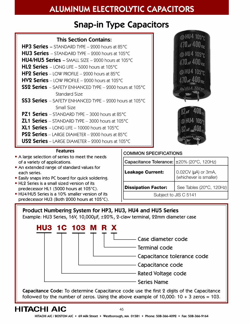
46
Snap-in Type Capacitors
Product Numbering System for HP3, HU3, HU4 and HU5 SeriesExample: HU3 Series, 16V, 10,000µF, ±20%, 2-claw terminal, 22mm diameter case
AIC
Case diameter code
Terminal code
Capacitance tolerance code
Capacitance code
Rated Voltage code
Series Name
HU3 1C 103 M R X
Capacitance Code: To determine Capacitance code use the first 2 digits of the Capacitancefollowed by the number of zeros. Using the above example of 10,000: 10 + 3 zeros = 103.
Features• A large selection of series to meet the needs of a variety of applications.• An extended range of standard values for each series.• Easily snaps into PC board for quick soldering.• HL2 Series is a small sized version of its predecessor HL1 (5000 hours at 105°C).• HU4/HU5 Series is a 10% smaller version of its predecessor HU3 (Both 2000 hours at 105°C).
ALUMINUM ELECTROLYTIC CAPACITORS
HITACHI AIC / BOSTON AIC • 69 Milk Street • Westborough, MA 01581 • Phone: 508-366-4092 • Fax: 508-366-9164
Capacitance Tolerance: ±20% (20°C, 120Hz)
Leakage Current: 0.02CV (µA) or 3mA, (whichever is smaller)
Dissipation Factor: See Tables (20°C, 120Hz)
COMMON SPECIFICATIONS
Subject to JIS C 5141
This Section Contains:HP3 Series – STANDARD TYPE – 2000 hours at 85°CHU3 Series – STANDARD TYPE – 2000 hours at 105°CHU4/HU5 Series – SMALL SIZE – 2000 hours at 105°CHL2 Series – LONG LIFE – 5000 hours at 105°CHF2 Series – LOW PROFILE – 2000 hours at 85°CHV2 Series – LOW PROFILE – 2000 hours at 105°CSS2 Series – SAFETY ENHANCED TYPE – 2000 hours at 105°C
Standard SizeSS3 Series – SAFETY ENHANCED TYPE – 2000 hours at 105°C
Small SizePZ1 Series – STANDARD TYPE – 3000 hours at 85°CZL1 Series – STANDARD TYPE – 3000 hours at 105°CXL1 Series – LONG LIFE – 10000 hours at 105°CPS2 Series – LARGE DIAMETER – 2000 hours at 85°CUS2 Series – LARGE DIAMETER – 2000 hours at 105°C
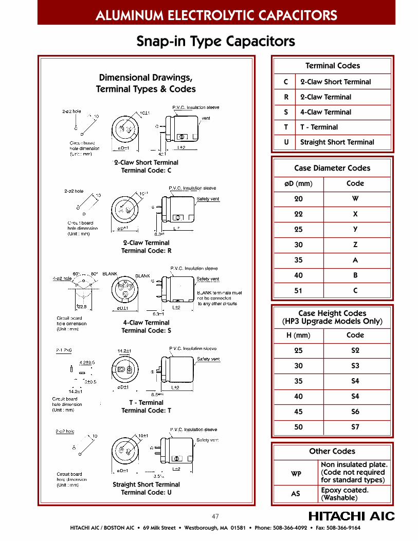
47
C 2-Claw Short Terminal
R 2-Claw Terminal
S 4-Claw Terminal
T T - Terminal
U Straight Short Terminal
ALUMINUM ELECTROLYTIC CAPACITORS
Snap-in Type Capacitors
Dimensional Drawings,Terminal Types & Codes
2-Claw TerminalTerminal Code: R
4-Claw TerminalTerminal Code: S
T - TerminalTerminal Code: T
Straight Short TerminalTerminal Code: U
Terminal Codes
AICHITACHI AIC / BOSTON AIC • 69 Milk Street • Westborough, MA 01581 • Phone: 508-366-4092 • Fax: 508-366-9164
Other Codes
WP
AS
Non insulated plate.(Code not requiredfor standard types)Epoxy coated.(Washable)
2-Claw Short TerminalTerminal Code: C Case Diameter Codes
øD (mm)
20
22
25
30
35
40
51
Code
W
X
Y
Z
A
B
C
Case Height Codes(HP3 Upgrade Models Only)
H (mm)
25
30
35
40
45
50
Code
S2
S3
S4
S4
S6
S7
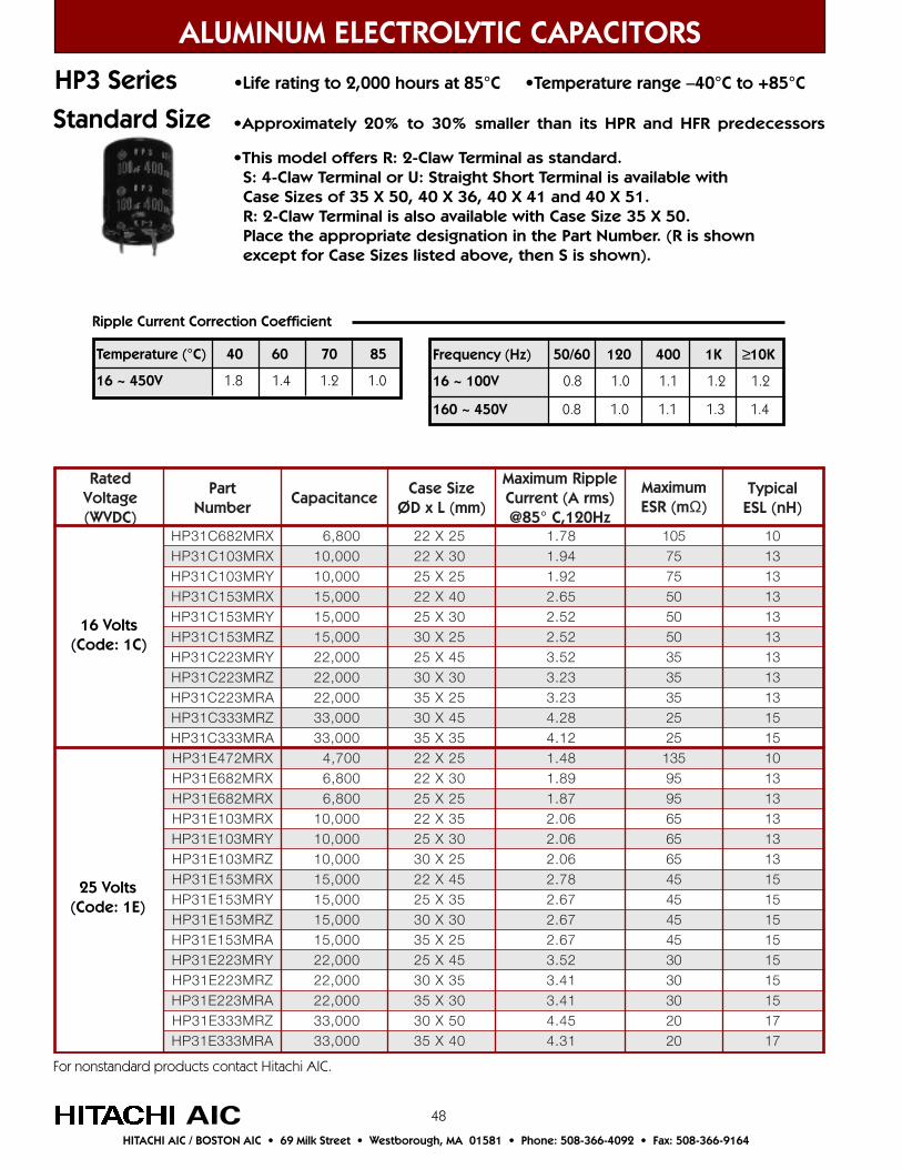
48
detaRegatloV)CDVW(
traPrebmuN
ecnaticapaCeziSesaC
)mm(LxDØ
elppiRmumixaMtnerruC A( smr )
zH021,C°58@
mumixaMm(RSE Ω)
lacipyT)Hn(LSE
XRM286C13PH 008,6 52X22 87.1 501 01XRM301C13PH 000,01 03X22 49.1 57 31YRM301C13PH 000,01 52X52 29.1 57 31XRM351C13PH 000,51 04X22 56.2 05 31YRM351C13PH 000,51 03X52 25.2 05 31ZRM351C13PH 000,51 52X03 25.2 05 31YRM322C13PH 000,22 54X52 25.3 53 31ZRM322C13PH 000,22 03X03 32.3 53 31ARM322C13PH 000,22 52X53 32.3 53 31ZRM333C13PH 000,33 54X03 82.4 52 51ARM333C13PH 000,33 53X53 21.4 52 51XRM274E13PH 007,4 52X22 84.1 531 01XRM286E13PH 008,6 03X22 98.1 59 31XRM286E13PH 008,6 52X52 78.1 59 31XRM301E13PH 000,01 53X22 60.2 56 31YRM301E13PH 000,01 03X52 60.2 56 31ZRM301E13PH 000,01 52X03 60.2 56 31XRM351E13PH 000,51 54X22 87.2 54 51YRM351E13PH 000,51 53X52 76.2 54 51ZRM351E13PH 000,51 03X03 76.2 54 51ARM351E13PH 000,51 52X53 76.2 54 51YRM322E13PH 000,22 54X52 25.3 03 51ZRM322E13PH 000,22 53X03 14.3 03 51ARM322E13PH 000,22 03X53 14.3 03 51ZRM333E13PH 000,33 05X03 54.4 02 71ARM333E13PH 000,33 04X53 13.4 02 71
ALUMINUM ELECTROLYTIC CAPACITORS
16 Volts(Code: 1C)
AIC
HP3 Series •Life rating to 2,000 hours at 85°C •Temperature range –40°C to +85°C
Ripple Current Correction Coefficient
•Approximately 20% to 30% smaller than its HPR and HFR predecessors
•This model offers R: 2-Claw Terminal as standard. S: 4-Claw Terminal or U: Straight Short Terminal is available with Case Sizes of 35 X 50, 40 X 36, 40 X 41 and 40 X 51. R: 2-Claw Terminal is also available with Case Size 35 X 50. Place the appropriate designation in the Part Number. (R is shown except for Case Sizes listed above, then S is shown).
Frequency (Hz) 50/60 120 400 1K ≥10K
16 ~ 100V 0.8 1.0 1.1 1.2 1.2
160 ~ 450V 0.8 1.0 1.1 1.3 1.4
Temperature (°C) 40 60 70 85
16 ~ 450V 1.8 1.4 1.2 1.0
25 Volts(Code: 1E)
HITACHI AIC / BOSTON AIC • 69 Milk Street • Westborough, MA 01581 • Phone: 508-366-4092 • Fax: 508-366-9164
Standard Size
For nonstandard products contact Hitachi AIC.
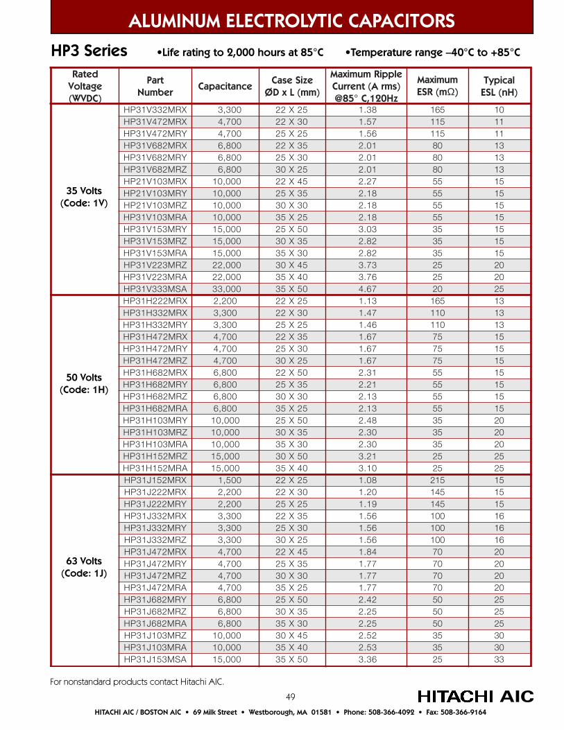
49
detaRegatloV)CDVW(
traPrebmuN
ecnaticapaCeziSesaC
)mm(LxDØ
elppiRmumixaMtnerruC A( smr )
zH021,C°58@
mumixaMm(RSE Ω)
lacipyT)Hn(LSE
XRM233V13PH 003,3 52X22 83.1 561 01XRM274V13PH 007,4 03X22 75.1 511 11YRM274V13PH 007,4 52X52 65.1 511 11XRM286V13PH 008,6 53X22 10.2 08 31YRM286V13PH 008,6 03X52 10.2 08 31ZRM286V13PH 008,6 52X03 10.2 08 31XRM301V12PH 000,01 54X22 72.2 55 51YRM301V12PH 000,01 53X52 81.2 55 51ZRM301V12PH 000,01 03X03 81.2 55 51ARM301V13PH 000,01 52X53 81.2 55 51YRM351V13PH 000,51 05X52 30.3 53 51ZRM351V13PH 000,51 53X03 28.2 53 51ARM351V13PH 000,51 03X53 28.2 53 51ZRM322V13PH 000,22 54X03 37.3 52 02ARM322V13PH 000,22 04X53 67.3 52 02ASM333V13PH 000,33 05X53 76.4 02 52XRM222H13PH 002,2 52X22 31.1 561 31XRM233H13PH 003,3 03X22 74.1 011 31YRM233H13PH 003,3 52X52 64.1 011 31XRM274H13PH 007,4 53X22 76.1 57 51YRM274H13PH 007,4 03X52 76.1 57 51ZRM274H13PH 007,4 52X03 76.1 57 51XRM286H13PH 008,6 05X22 13.2 55 51YRM286H13PH 008,6 53X52 12.2 55 51ZRM286H13PH 008,6 03X03 31.2 55 51ARM286H13PH 008,6 52X53 31.2 55 51YRM301H13PH 000,01 05X52 84.2 53 02ZRM301H13PH 000,01 53X03 03.2 53 02ARM301H13PH 000,01 03X53 03.2 53 02ZRM251H13PH 000,51 05X03 12.3 52 52ARM251H13PH 000,51 04X53 01.3 52 52XRM251J13PH 005,1 52X22 80.1 512 51XRM222J13PH 002,2 03X22 02.1 541 51YRM222J13PH 002,2 52X52 91.1 541 51XRM233J13PH 003,3 53X22 65.1 001 61YRM233J13PH 003,3 03X52 65.1 001 61ZRM233J13PH 003,3 52X03 65.1 001 61XRM274J13PH 007,4 54X22 48.1 07 02YRM274J13PH 007,4 53X52 77.1 07 02ZRM274J13PH 007,4 03X03 77.1 07 02ARM274J13PH 007,4 52X53 77.1 07 02YRM286J13PH 008,6 05X52 24.2 05 52ZRM286J13PH 008,6 53X03 52.2 05 52ARM286J13PH 008,6 03X53 52.2 05 52ZRM301J13PH 000,01 54X03 25.2 53 03ARM301J13PH 000,01 04X53 35.2 53 03ASM351J13PH 000,51 05X53 63.3 52 33
ALUMINUM ELECTROLYTIC CAPACITORS
HP3 Series •Life rating to 2,000 hours at 85°C •Temperature range –40°C to +85°C
AIC
50 Volts(Code: 1H)
63 Volts(Code: 1J)
HITACHI AIC / BOSTON AIC • 69 Milk Street • Westborough, MA 01581 • Phone: 508-366-4092 • Fax: 508-366-9164
For nonstandard products contact Hitachi AIC.
35 Volts(Code: 1V)
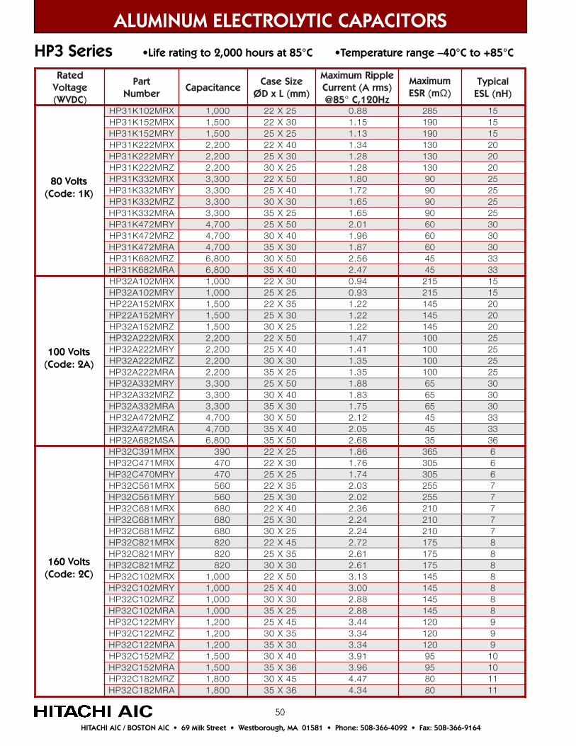
50
detaRegatloV)CDVW(
traPrebmuN
ecnaticapaCeziSesaC
)mm(LxDØ
elppiRmumixaMtnerruC A( )smr
zH021,C°58@
mumixaMm(RSE Ω)
lacipyT)Hn(LSE
XRM201K13PH 000,1 52X22 88.0 582 51XRM251K13PH 005,1 03X22 51.1 091 51YRM251K13PH 005,1 52X52 31.1 091 51XRM222K13PH 002,2 04X22 43.1 031 02YRM222K13PH 002,2 03X52 82.1 031 02ZRM222K13PH 002,2 52X03 82.1 031 02XRM233K13PH 003,3 05X22 08.1 09 52YRM233K13PH 003,3 04X52 27.1 09 52ZRM233K13PH 003,3 03X03 56.1 09 52ARM233K13PH 003,3 52X53 56.1 09 52YRM274K13PH 007,4 05X52 10.2 06 03ZRM274K13PH 007,4 04X03 69.1 06 03ARM274K13PH 007,4 03X53 78.1 06 03ZRM286K13PH 008,6 05X03 65.2 54 33ARM286K13PH 008,6 04X53 74.2 54 33XRM201A23PH 000,1 03X22 49.0 512 51YRM201A23PH 000,1 52X52 39.0 512 51XRM251A22PH 005,1 53X22 22.1 541 02YRM251A22PH 005,1 03X52 22.1 541 02ZRM251A23PH 005,1 52X03 22.1 541 02XRM222A23PH 002,2 05X22 74.1 001 52YRM222A23PH 002,2 04X52 14.1 001 52ZRM222A23PH 002,2 03X03 53.1 001 52ARM222A23PH 002,2 52X53 53.1 001 52YRM233A23PH 003,3 05X52 88.1 56 03ZRM233A23PH 003,3 04X03 38.1 56 03ARM233A23PH 003,3 03X53 57.1 56 03ZRM274A23PH 007,4 05X03 21.2 54 33ARM274A23PH 007,4 04X53 50.2 54 33ASM286A23PH 008,6 05X53 86.2 53 63XRM193C23PH 093 52X22 68.1 563 6XRM174C23PH 074 03X22 67.1 503 6YRM074C23PH 074 52X52 47.1 503 6XRM165C23PH 065 53X22 30.2 552 7YRM165C23PH 065 03X52 20.2 552 7XRM186C23PH 086 04X22 63.2 012 7YRM186C23PH 086 03X52 42.2 012 7ZRM186C23PH 086 52X03 42.2 012 7XRM128C23PH 028 54X22 27.2 571 8YRM128C23PH 028 53X52 16.2 571 8ZRM128C23PH 028 03X03 16.2 571 8XRM201C23PH 000,1 05X22 31.3 541 8YRM201C23PH 000,1 04X52 00.3 541 8ZRM201C23PH 000,1 03X03 88.2 541 8ARM201C23PH 000,1 52X53 88.2 541 8YRM221C23PH 002,1 54X52 44.3 021 9ZRM221C23PH 002,1 53X03 43.3 021 9ARM221C23PH 002,1 03X53 43.3 021 9ZRM251C23PH 005,1 04X03 19.3 59 01ARM251C23PH 005,1 63X53 69.3 59 01ZRM281C23PH 008,1 54X03 74.4 08 11ARM281C23PH 008,1 63X53 43.4 08 11
ALUMINUM ELECTROLYTIC CAPACITORS
HP3 Series •Life rating to 2,000 hours at 85°C •Temperature range –40°C to +85°C
160 Volts(Code: 2C)
AICHITACHI AIC / BOSTON AIC • 69 Milk Street • Westborough, MA 01581 • Phone: 508-366-4092 • Fax: 508-366-9164
80 Volts(Code: 1K)
100 Volts(Code: 2A)
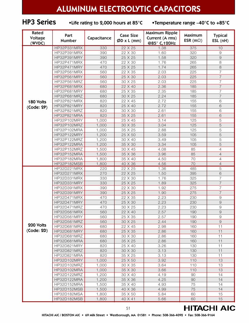
51
detaRegatloV)CDVW(
traPrebmuN
ecnaticapaCeziSesaC
)mm(LxDØ
elppiRmumixaMtnerruC A( smr )
zH021,C°58@
mumixaMm(RSE Ω)
lacipyT)Hn(LSE
XRM133P23PH 033 52X22 83.1 573 01XRM193P23PH 093 03X22 06.1 023 9YRM193P23PH 093 52X52 85.1 023 9XRM174P23PH 074 03X22 67.1 562 8YRM174P23PH 074 52X52 47.1 562 8XRM165P23PH 065 53X22 30.2 522 7YRM165P23PH 065 03X52 30.2 522 7ZRM165P23PH 065 52X03 30.2 522 7XRM186P23PH 086 04X22 63.2 581 7YRM186P23PH 086 53X52 53.2 581 7ZRM186P23PH 086 52X03 42.2 581 7XRM128P23PH 028 54X22 27.2 551 6YRM128P23PH 028 04X52 27.2 551 6ZRM128P23PH 028 03X03 16.2 551 6ARM128P23PH 028 52X53 16.2 551 6YRM201P23PH 000,1 54X52 41.3 521 5ZRM201P23PH 000,1 53X03 40.3 521 5ARM201P23PH 000,1 52X53 88.2 521 5YRM221P23PH 002,1 05X52 95.3 501 5ZRM221P23PH 002,1 04X03 94.3 501 5ARM221P23PH 002,1 03X53 43.3 501 5ZRM251P23PH 005,1 54X03 80.4 58 4ARM251P23PH 005,1 63X53 69.3 58 4ARM281P23PH 008,1 04X53 05.4 07 4BSM281P23PH 008,1 63X04 65.4 07 4XRM122D23PH 022 52X22 63.1 584 5XRM172D23PH 072 52X22 05.1 593 6XRM133D23PH 033 03X22 67.1 523 7YRM133D23PH 033 52X52 98.1 523 7XRM193D23PH 093 03X22 29.1 572 7YRM193D23PH 093 52X52 09.1 572 7XRM174D23PH 074 53X22 32.2 032 9YRM174D23PH 074 03X52 32.2 032 9ZRM174D23PH 074 52X03 32.2 032 9XRM165D23PH 065 04X22 75.2 091 9YRM165D23PH 065 53X52 75.2 091 9ZRM165D23PH 065 52X03 44.2 091 9XRM186D23PH 086 54X22 89.2 061 11YRM186D23PH 086 53X52 68.2 061 11ZRM186D23PH 086 03X03 68.2 061 11ARM186D23PH 086 52X53 68.2 061 11YRM128D23PH 028 04X52 62.3 031 11ZRM128D23PH 028 03X03 31.3 031 11ARM128D23PH 028 52X53 31.3 031 11YRM201D23PH 000,1 05X52 29.3 011 31ZRM201D23PH 000,1 53X03 46.3 011 31ARM201D23PH 000,1 03X53 66.3 011 31ZRM221D23PH 002,1 04X03 91.4 09 41ARM221D23PH 002,1 63X53 52.4 09 41ARM251D23PH 005,1 04X53 39.4 57 41BSM251D23PH 005,1 63X04 99.4 57 41ASM281D23PH 008,1 05X53 48.5 06 51BSM281D23PH 008,1 14X04 66.5 06 51
ALUMINUM ELECTROLYTIC CAPACITORS
HP3 Series •Life rating to 2,000 hours at 85°C •Temperature range –40°C to +85°C
AIC
200 Volts(Code: 2D)
HITACHI AIC / BOSTON AIC • 69 Milk Street • Westborough, MA 01581 • Phone: 508-366-4092 • Fax: 508-366-9164
180 Volts(Code: 2P)

52
detaRegatloV)CDVW(
traPrebmuN
ecnaticapaCeziSesaC
)mm(LxDØ
elppiRmumixaMtnerruC A( smr )
zH021,C°58@
mumixaMm(RSE Ω)
lacipyT)Hn(LSE
XRM122E23PH 022 52X22 63.1 584 5XRM172E23PH 072 03X22 06.1 593 6YRM172E23PH 072 52X52 85.1 593 6XRM133E23PH 033 53X22 78.1 523 7YRM133E23PH 033 03X52 68.1 523 7XRM193E23PH 093 53X22 40.2 572 8YRM193E23PH 093 03X52 40.2 572 8ZRM193E23PH 093 52X03 40.2 572 8XRM174E23PH 074 04X22 53.2 032 8YRM174E23PH 074 53X52 53.2 032 8ZRM174E23PH 074 52X03 42.2 032 8ARM174E23PH 074 52X53 83.2 032 8XRM165E23PH 065 05X22 18.2 091 9YRM165E23PH 065 04X52 96.2 091 9ZRM165E23PH 065 03X03 95.2 091 9ARM165E23PH 065 52X53 95.2 091 9YRM186E23PH 086 54X52 11.3 061 9ZRM186E23PH 086 53X03 10.3 061 9ARM186E23PH 086 03X53 10.3 061 9YRM128E23PH 028 05X52 55.3 031 01ZRM128E23PH 028 04X03 55.3 031 01ARM128E23PH 028 03X53 13.3 031 01ZRM201E23PH 000,1 54X03 00.4 011 11ARM201E23PH 000,1 63X53 88.3 011 11ZRM221E23PH 002,1 05X03 55.4 09 11ARM221E23PH 002,1 04X53 04.4 09 11BSM221E23PH 002,1 63X04 64.4 57 21ASM251E23PH 005,1 05X53 43.5 57 21BSM251E23PH 005,1 14X04 92.5 06 31BSM281E23PH 008,1 15X04 11.6 06 31XRM101V23PH 001 52X22 67.0 5601 3XRM121V23PH 021 03X22 98.0 588 3YRM121V23PH 021 52X52 88.0 588 3XRM151V23PH 051 03X22 99.0 017 4YRM151V23PH 051 52X52 89.0 017 4XRM181V23PH 081 53X22 51.1 095 4YRM181V23PH 081 03X52 51.1 095 4ZRM181V23PH 081 52X03 51.1 095 4XRM122V23PH 022 04X22 43.1 584 5YRM122V23PH 022 53X52 43.1 584 5ZRM122V23PH 022 52X03 82.1 584 5XRM172V23PH 072 05X22 36.1 593 5YRM172V23PH 072 04X52 65.1 593 5ZRM172V23PH 072 03X03 05.1 593 5ARM172V23PH 072 52X53 05.1 593 5YRM133V23PH 033 54X52 08.1 523 6ZRM133V23PH 033 53X03 07.1 523 6ARM133V23PH 033 03X53 57.1 523 6YRM193V23PH 093 05X52 40.2 572 6ZRM193V23PH 093 04X03 99.1 572 6ARM193V23PH 093 03X53 09.1 572 6ZRM174V23PH 074 04X03 91.2 032 7ARM174V23PH 074 63X53 66.3 032 7ZRM165V23PH 065 05X03 95.2 091 7ARM165V23PH 065 04X53 45.2 091 7BSM165V23PH 065 63X04 45.2 091 7ARM186V23PH 086 54X53 88.2 061 9BSM186V23PH 086 14X04 09.2 061 9
ALUMINUM ELECTROLYTIC CAPACITORS
HP3 Series •Life rating to 2,000 hours at 85°C •Temperature range –40°C to +85°C
AIC
350 Volts(Code: 2V)
HITACHI AIC / BOSTON AIC • 69 Milk Street • Westborough, MA 01581 • Phone: 508-366-4092 • Fax: 508-366-9164
250 Volts(Code: 2E)
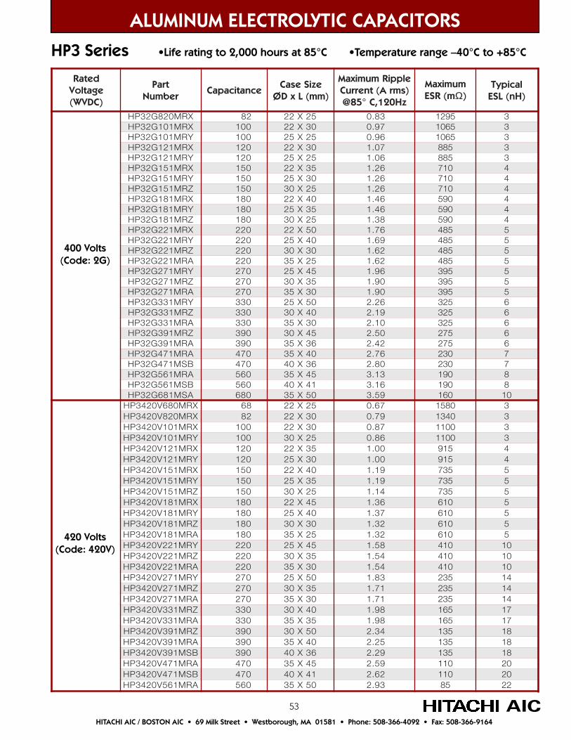
53
detaRegatloV)CDVW(
traPrebmuN
ecnaticapaCeziSesaC
)mm(LxDØ
elppiRmumixaMtnerruC A( smr )
zH021,C°58@
mumixaMm(RSE Ω)
lacipyT)Hn(LSE
XRM028G23PH 28 52X22 38.0 5921 3XRM101G23PH 001 03X22 79.0 5601 3YRM101G23PH 001 52X52 69.0 5601 3XRM121G23PH 021 03X22 70.1 588 3YRM121G23PH 021 52X52 60.1 588 3XRM151G23PH 051 53X22 62.1 017 4YRM151G23PH 051 03X52 62.1 017 4ZRM151G23PH 051 52X03 62.1 017 4XRM181G23PH 081 04X22 64.1 095 4YRM181G23PH 081 53X52 64.1 095 4ZRM181G23PH 081 52X03 83.1 095 4XRM122G23PH 022 05X22 67.1 584 5YRM122G23PH 022 04X52 96.1 584 5ZRM122G23PH 022 03X03 26.1 584 5ARM122G23PH 022 52X53 26.1 584 5YRM172G23PH 072 54X52 69.1 593 5ZRM172G23PH 072 53X03 09.1 593 5ARM172G23PH 072 03X53 09.1 593 5YRM133G23PH 033 05X52 62.2 523 6ZRM133G23PH 033 04X03 91.2 523 6ARM133G23PH 033 03X53 01.2 523 6ZRM193G23PH 093 54X03 05.2 572 6ARM193G23PH 093 63X53 24.2 572 6ARM174G23PH 074 04X53 67.2 032 7BSM174G23PH 074 63X04 08.2 032 7ARM165G23PH 065 54X53 31.3 091 8BSM165G23PH 065 14X04 61.3 091 8ASM186G23PH 086 05X53 95.3 061 01
XRM086V0243PH 86 52X22 76.0 0851 3XRM028V0243PH 28 03X22 97.0 0431 3XRM101V0243PH 001 03X22 78.0 0011 3YRM101V0243PH 001 52X03 68.0 0011 3XRM121V0243PH 021 53X22 00.1 519 4YRM121V0243PH 021 03X52 00.1 519 4XRM151V0243PH 051 04X22 91.1 537 5YRM151V0243PH 051 53X52 91.1 537 5ZRM151V0243PH 051 52X03 41.1 537 5XRM181V0243PH 081 54X22 63.1 016 5YRM181V0243PH 081 04X52 73.1 016 5ZRM181V0243PH 081 03X03 23.1 016 5ARM181V0243PH 081 52X53 23.1 016 5YRM122V0243PH 022 54X52 85.1 014 01ZRM122V0243PH 022 53X03 45.1 014 01ARM122V0243PH 022 03X53 45.1 014 01YRM172V0243PH 072 05X52 38.1 532 41ZRM172V0243PH 072 53X03 17.1 532 41ARM172V0243PH 072 03X53 17.1 532 41ZRM133V0243PH 033 04X03 89.1 561 71ARM133V0243PH 033 53X53 89.1 561 71ZRM193V0243PH 093 05X03 43.2 531 81ARM193V0243PH 093 04X53 52.2 531 81BSM193V0243PH 093 63X04 92.2 531 81ARM174V0243PH 074 54X53 95.2 011 02BSM174V0243PH 074 14X04 26.2 011 02ARM165V0243PH 065 05X53 39.2 58 22
ALUMINUM ELECTROLYTIC CAPACITORS
HP3 Series •Life rating to 2,000 hours at 85°C •Temperature range –40°C to +85°C
AICHITACHI AIC / BOSTON AIC • 69 Milk Street • Westborough, MA 01581 • Phone: 508-366-4092 • Fax: 508-366-9164
400 Volts(Code: 2G)
420 Volts(Code: 420V)

54
450 Volts(Code: 2W)
detaRegatloV)CDVW(
traPrebmuN
ecnaticapaCeziSesaC
)mm(LxDØ
elppiRmumixaMtnerruC A( smr )
zH021,C°58@
mumixaMm(RSE Ω)
lacipyT)Hn(LSE
XRM028W23PH 28 03X22 98.0 0431 3YRM028W23PH 28 52X52 88.0 0431 3XRM101W23PH 101 53X22 30.1 0011 3YRM101W23PH 101 03X52 30.1 0011 3ZRM101W23PH 101 52X03 30.1 0011 3XRM121W23PH 021 04X22 91.1 519 4YRM121W23PH 021 03X52 31.1 519 4ZRM121W23PH 021 52X03 31.1 519 4XRM151W23PH 051 54X22 93.1 537 5YRM151W23PH 051 53X52 43.1 537 5ZRM151W23PH 051 03X03 43.1 537 5XRM181W23PH 081 05X22 06.1 016 5YRM181W23PH 081 04X52 25.1 016 5ZRM181W23PH 081 03X03 64.1 016 5ARM181W23PH 081 52X53 64.1 016 5YRM122W23PH 022 54X52 67.1 005 5ZRM122W23PH 022 53X03 27.1 005 5ARM122W23PH 022 03X53 27.1 005 5ZRM172W23PH 072 04X03 99.1 014 01ARM172W23PH 072 63X53 20.2 014 01ZRM133W23PH 033 54X03 92.2 533 01ARM133W23PH 033 63X53 32.2 533 01ARM193W23PH 093 04X53 15.2 582 21BSM193W23PH 093 63X04 45.2 582 21ARM174W23PH 074 54X53 88.2 532 41BSM174W23PH 074 14X04 98.2 532 41BSM165W23PH 065 15X04 14.3 002 61
ALUMINUM ELECTROLYTIC CAPACITORS
HP3 Series •Life rating to 2,000 hours at 85°C •Temperature range –40°C to +85°C
AICHITACHI AIC / BOSTON AIC • 69 Milk Street • Westborough, MA 01581 • Phone: 508-366-4092 • Fax: 508-366-9164
For nonstandard products contact Hitachi AIC.
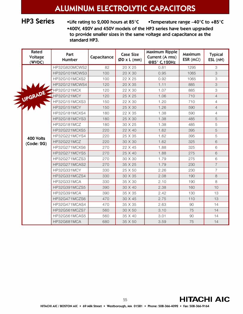
55
ALUMINUM ELECTROLYTIC CAPACITORS
HP3 Series •Life rating to 2,000 hours at 85°C •Temperature range –40°C to +85°C •400V, 420V and 450V models of the HP3 series have been upgraded to provide smaller sizes in the same voltage and capacitance as the standard HP3.
AICHITACHI AIC / BOSTON AIC • 69 Milk Street • Westborough, MA 01581 • Phone: 508-366-4092 • Fax: 508-366-9164
detaRegatloV)CDVW(
traPrebmuN
ecnaticapaCeziSesaC
)mm(LxDØ
elppiRmumixaMtnerruC A( smr )
zH021,C°58@
mumixaMm(RSE Ω)
lacipyT)Hn(LSE
2SWCM028G23PH 28 52X02 18.0 5921 3
3SWCM101G23PH 001 03X02 59.0 5601 3
2SXCM101G23PH 001 52X22 29.0 5601 3
4SWCM121G23PH 021 53X02 11.1 588 3
XCM121G23PH 021 03X22 70.1 588 3
YCM121G23PH 021 52X52 60.1 017 4
3SXCM151G23PH 051 03X22 02.1 017 4
YCM151G23PH 051 03X52 62.1 095 4
4SXCM181G23PH 081 53X22 83.1 095 4
3SYCM181G23PH 081 03X52 83.1 584 5
ZCM181G23PH 081 52X03 83.1 584 5
5SXCM122G23PH 022 04X22 26.1 593 5
4SYCM122G23PH 022 53X52 26.1 593 5
ZCM122G23PH 022 03X03 26.1 523 6
6SXCM172G23PH 072 54X22 88.1 523 6
5SYCM172G23PH 072 04X52 88.1 572 6
3SZCM172G23PH 072 03X03 97.1 572 6
2SACM172G23PH 072 52X53 97.1 032 7
YCM133G23PH 033 05X52 62.2 032 7
4SZCM133G23PH 033 53X03 80.2 091 8
ACM133G23PH 033 03X53 01.2 091 8
5SZCM193G23PH 093 04X03 83.2 061 01
ACM193G23PH 093 53X53 24.2 031 31
6SZCM174G23PH 074 54X03 57.2 011 31
4SACM174G23PH 074 53X53 36.2 09 41
7SZCM165G23PH 065 05X03 01.3 57 41
5SACM165G23PH 065 04X53 10.3 09 41
ACM186G23PH 086 05X53 95.3 57 41
400 Volts(Code: 2G)
UPGRADE
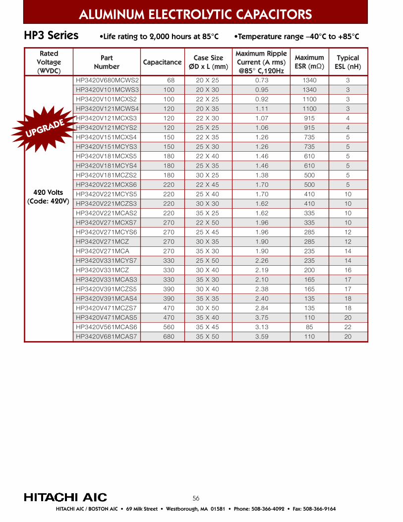
56
ALUMINUM ELECTROLYTIC CAPACITORS
HP3 Series •Life rating to 2,000 hours at 85°C •Temperature range –40°C to +85°C
AICHITACHI AIC / BOSTON AIC • 69 Milk Street • Westborough, MA 01581 • Phone: 508-366-4092 • Fax: 508-366-9164
detaRegatloV)CDVW(
traPrebmuN
ecnaticapaCeziSesaC
)mm(LxDØ
elppiRmumixaMtnerruC A( smr )
zH021,C°58@
mumixaMm(RSE Ω)
lacipyT)Hn(LSE
2SWCM086V0243PH 86 52X02 37.0 0431 3
3SWCM101V0243PH 001 03X02 59.0 0431 3
2SXCM101V0243PH 001 52X22 29.0 0011 3
4SWCM121V0243PH 021 53X02 11.1 0011 3
3SXCM121V0243PH 021 03X22 70.1 519 4
2SYCM121V0243PH 021 52X52 60.1 519 4
4SXCM151V0243PH 051 53X22 62.1 537 5
3SYCM151V0243PH 051 03X52 62.1 537 5
5SXCM181V0243PH 081 04X22 64.1 016 5
4SYCM181V0243PH 081 53X52 64.1 016 5
2SZCM181V0243PH 081 52X03 83.1 005 5
6SXCM122V0243PH 022 54X22 07.1 005 5
5SYCM122V0243PH 022 04X52 07.1 014 01
3SZCM122V0243PH 022 03X03 26.1 014 01
2SACM122V0243PH 022 52X53 26.1 533 01
7SXCM172V0243PH 072 05X22 69.1 533 01
6SYCM172V0243PH 072 54X52 69.1 582 21
ZCM172V0243PH 072 53X03 09.1 582 21
ACM172V0243PH 072 03X53 09.1 532 41
7SYCM133V0243PH 033 05X52 62.2 532 41
ZCM133V0243PH 033 04X03 91.2 002 61
3SACM133V0243PH 033 03X53 01.2 561 71
5SZCM193V0243PH 093 04X03 83.2 561 71
4SACM193V0243PH 093 53X53 04.2 531 81
7SZCM174V0243PH 074 05X03 48.2 531 81
5SACM174V0243PH 074 04X53 57.3 011 02
6SACM165V0243PH 065 54X53 31.3 58 22
7SACM186V0243PH 086 05X53 95.3 011 02
420 Volts(Code: 420V)
UPGRADE
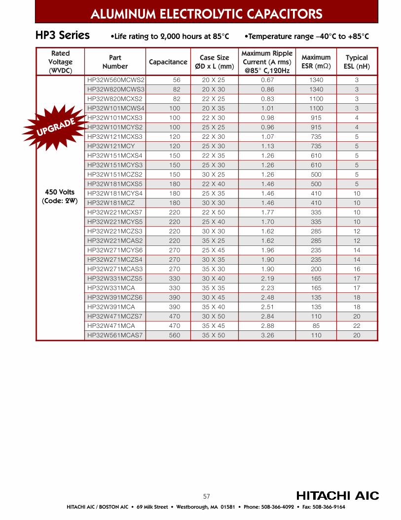
57
ALUMINUM ELECTROLYTIC CAPACITORS
HP3 Series •Life rating to 2,000 hours at 85°C •Temperature range –40°C to +85°C
AICHITACHI AIC / BOSTON AIC • 69 Milk Street • Westborough, MA 01581 • Phone: 508-366-4092 • Fax: 508-366-9164
detaRegatloV)CDVW(
traPrebmuN
ecnaticapaCeziSesaC
)mm(LxDØ
elppiRmumixaMtnerruC A( smr )
zH021,C°58@
mumixaMm(RSE Ω)
lacipyT)Hn(LSE
2SWCM065W23PH 65 52X02 76.0 0431 3
3SWCM028W23PH 28 03X02 68.0 0431 3
2SXCM028W23PH 28 52X22 38.0 0011 3
4SWCM101W23PH 001 53X02 10.1 0011 3
3SXCM101W23PH 001 03X22 89.0 519 4
2SYCM101W23PH 001 52X52 69.0 519 4
3SXCM121W23PH 021 03X22 70.1 537 5
YCM121W23PH 021 03X52 31.1 537 5
4SXCM151W23PH 051 53X22 62.1 016 5
3SYCM151W23PH 051 03X52 62.1 016 5
2SZCM151W23PH 051 52X03 62.1 005 5
5SXCM181W23PH 081 04X22 64.1 005 5
4SYCM181W23PH 081 53X52 64.1 014 01
ZCM181W23PH 081 03X03 64.1 014 01
7SXCM122W23PH 022 05X22 77.1 533 01
5SYCM122W23PH 022 04X52 07.1 533 01
3SZCM122W23PH 022 03X03 26.1 582 21
2SACM122W23PH 022 52X53 26.1 582 21
6SYCM172W23PH 072 54X52 69.1 532 41
4SZCM172W23PH 072 53X03 09.1 532 41
3SACM172W23PH 072 03X53 09.1 002 61
5SZCM133W23PH 033 04X03 91.2 561 71
ACM133W23PH 033 53X53 32.2 561 71
6SZCM193W23PH 093 54X03 84.2 531 81
ACM193W23PH 093 04X53 15.2 531 81
7SZCM174W23PH 074 05X03 48.2 011 02
ACM174W23PH 074 54X53 88.2 58 22
7SACM165W23PH 065 05X53 62.3 011 02
450 Volts(Code: 2W)
UPGRADE
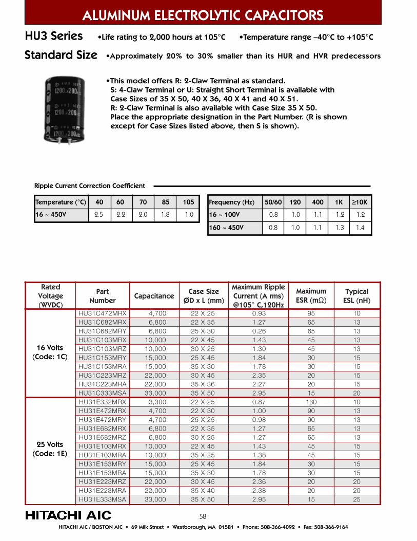
58
ALUMINUM ELECTROLYTIC CAPACITORSHU3 Series •Life rating to 2,000 hours at 105°C •Temperature range –40°C to +105°C
Ripple Current Correction Coefficient
•Approximately 20% to 30% smaller than its HUR and HVR predecessors
•This model offers R: 2-Claw Terminal as standard. S: 4-Claw Terminal or U: Straight Short Terminal is available with Case Sizes of 35 X 50, 40 X 36, 40 X 41 and 40 X 51. R: 2-Claw Terminal is also available with Case Size 35 X 50. Place the appropriate designation in the Part Number. (R is shown except for Case Sizes listed above, then S is shown).
Frequency (Hz) 50/60 120 400 1K ≥10K
16 ~ 100V 0.8 1.0 1.1 1.2 1.2
160 ~ 450V 0.8 1.0 1.1 1.3 1.4
Temperature (°C) 40 60 70 85 105
16 ~ 450V 2.5 2.2 2.0 1.8 1.0
detaRegatloV)CDVW(
traPrebmuN
ecnaticapaCeziSesaC
)mm(LxDØ
elppiRmumixaMtnerruC A( smr )
zH021,C°501@
mumixaMm(RSE Ω)
lacipyT)Hn(LSE
XRM274C13UH 007,4 52X22 39.0 59 01XRM286C13UH 008,6 53X22 72.1 56 31YRM286C13UH 008,6 03X52 62.0 56 31XRM301C13UH 000,01 54X22 34.1 54 31ZRM301C13UH 000,01 52X03 03.1 54 31YRM351C13UH 000,51 54X52 48.1 03 51ARM351C13UH 000,51 03X53 87.1 03 51ZRM322C13UH 000,22 54X03 53.2 02 51ARM322C13UH 000,22 63X53 72.2 02 51ASM333C13UH 000,33 05X53 59.2 51 02XRM233E13UH 003,3 52X22 78.0 031 01XRM274E13UH 007,4 03X22 00.1 09 31YRM274E13UH 007,4 52X52 89.0 09 31XRM286E13UH 008,6 53X22 72.1 56 31ZRM286E13UH 008,6 52X03 72.1 56 31XRM301E13UH 000,01 54X22 34.1 54 51ARM301E13UH 000,01 52X53 83.1 54 51YRM351E13UH 000,51 54X52 48.1 03 51ARM351E13UH 000,51 03X53 87.1 03 51ZRM322E13UH 000,22 54X03 63.2 02 02ARM322E13UH 000,22 04X53 83.2 02 02ASM333E13UH 000,33 05X53 59.2 51 52
25 Volts(Code: 1E)
16 Volts(Code: 1C)
AICHITACHI AIC / BOSTON AIC • 69 Milk Street • Westborough, MA 01581 • Phone: 508-366-4092 • Fax: 508-366-9164
Standard Size
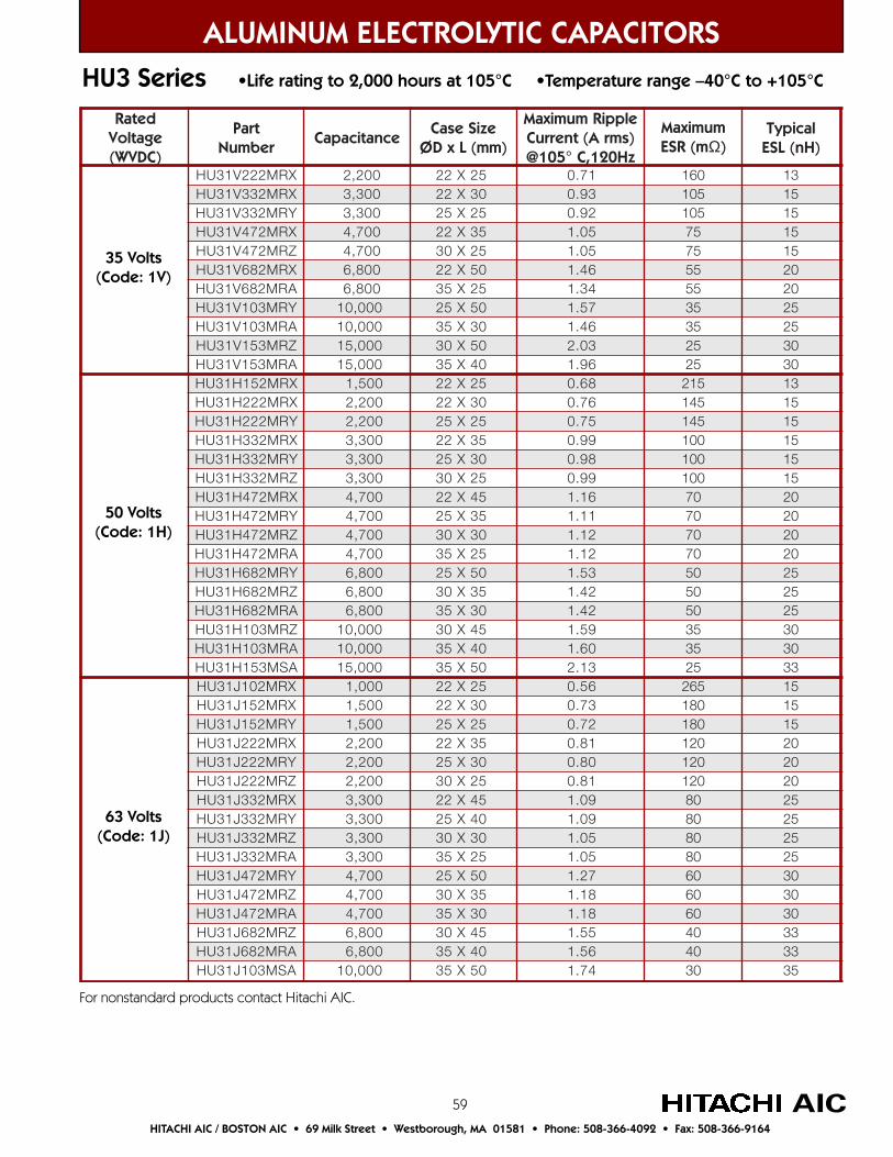
59
ALUMINUM ELECTROLYTIC CAPACITORSHU3 Series •Life rating to 2,000 hours at 105°C •Temperature range –40°C to +105°C
AIC
detaRegatloV)CDVW(
traPrebmuN
ecnaticapaCeziSesaC
)mm(LxDØ
elppiRmumixaMtnerruC )smrA(
zH021,C°501@
mumixaMm(RSE Ω)
lacipyT)Hn(LSE
XRM222V13UH 002,2 52X22 17.0 061 31XRM233V13UH 003,3 03X22 39.0 501 51YRM233V13UH 003,3 52X52 29.0 501 51XRM274V13UH 007,4 53X22 50.1 57 51ZRM274V13UH 007,4 52X03 50.1 57 51XRM286V13UH 008,6 05X22 64.1 55 02ARM286V13UH 008,6 52X53 43.1 55 02YRM301V13UH 000,01 05X52 75.1 53 52ARM301V13UH 000,01 03X53 64.1 53 52ZRM351V13UH 000,51 05X03 30.2 52 03ARM351V13UH 000,51 04X53 69.1 52 03XRM251H13UH 005,1 52X22 86.0 512 31XRM222H13UH 002,2 03X22 67.0 541 51YRM222H13UH 002,2 52X52 57.0 541 51XRM233H13UH 003,3 53X22 99.0 001 51YRM233H13UH 003,3 03X52 89.0 001 51ZRM233H13UH 003,3 52X03 99.0 001 51XRM274H13UH 007,4 54X22 61.1 07 02YRM274H13UH 007,4 53X52 11.1 07 02ZRM274H13UH 007,4 03X03 21.1 07 02ARM274H13UH 007,4 52X53 21.1 07 02YRM286H13UH 008,6 05X52 35.1 05 52ZRM286H13UH 008,6 53X03 24.1 05 52ARM286H13UH 008,6 03X53 24.1 05 52ZRM301H13UH 000,01 54X03 95.1 53 03ARM301H13UH 000,01 04X53 06.1 53 03ASM351H13UH 000,51 05X53 31.2 52 33XRM201J13UH 000,1 52X22 65.0 562 51XRM251J13UH 005,1 03X22 37.0 081 51YRM251J13UH 005,1 52X52 27.0 081 51XRM222J13UH 002,2 53X22 18.0 021 02YRM222J13UH 002,2 03X52 08.0 021 02ZRM222J13UH 002,2 52X03 18.0 021 02XRM233J13UH 003,3 54X22 90.1 08 52YRM233J13UH 003,3 04X52 90.1 08 52ZRM233J13UH 003,3 03X03 50.1 08 52ARM233J13UH 003,3 52X53 50.1 08 52YRM274J13UH 007,4 05X52 72.1 06 03ZRM274J13UH 007,4 53X03 81.1 06 03ARM274J13UH 007,4 03X53 81.1 06 03ZRM286J13UH 008,6 54X03 55.1 04 33ARM286J13UH 008,6 04X53 65.1 04 33ASM301J13UH 000,01 05X53 47.1 03 53
35 Volts(Code: 1V)
50 Volts(Code: 1H)
63 Volts(Code: 1J)
HITACHI AIC / BOSTON AIC • 69 Milk Street • Westborough, MA 01581 • Phone: 508-366-4092 • Fax: 508-366-9164
For nonstandard products contact Hitachi AIC.

60
ALUMINUM ELECTROLYTIC CAPACITORSHU3 Series •Life rating to 2,000 hours at 105°C •Temperature range –40°C to +105°C
AIC
detaRegatloV)CDVW(
traPrebmuN
ecnaticapaCeziSesaC
)mm(LxDØ
elppiRmumixaMtnerruC A( smr )
zH021,C°501@
mumixaMm(RSE Ω)
lacipyT)Hn(LSE
XRM201K13UH 000,1 03X22 95.0 032 51YRM201K13UH 000,1 52X52 95.0 032 51XRM251K13UH 005,1 53X22 77.0 551 02ZRM251K13UH 005,1 52X03 77.0 551 02XRM222K13UH 002,2 05X22 39.0 501 52ARM222K13UH 002,2 52X53 58.0 501 52YRM233K13UH 003,3 05X52 91.1 07 03ARM233K13UH 003,3 03X53 11.1 07 03ZRM274K13UH 007,4 05X03 43.1 05 33ARM274K13UH 007,4 04X53 03.1 05 33ASM286K13UH 008,6 05X53 96.1 53 53XRM201A23UH 000,1 03X22 95.0 081 02YRM201A23UH 000,1 52X52 95.0 081 02XRM251A23UH 005,1 04X22 18.0 031 52ZRM251A23UH 005,1 52X03 77.0 031 52YRM222A23UH 002,2 54X52 39.0 09 03ZRM222A23UH 002,2 53X03 09.0 09 03ZRM233A23UH 003,3 54X03 12.1 06 33ARM233A23UH 003,3 63X53 61.1 06 33ARM274A23UH 007,4 54X53 53.1 54 53XRM133C23UH 033 52X22 89.0 034 6XRM193C23UH 093 03X22 01.1 563 6YRM193C23UH 093 52X52 90.1 563 6XRM174C23UH 074 03X22 12.1 503 6YRM174C23UH 074 52X52 91.1 503 6XRM165C23UH 065 53X22 04.1 552 7ZRM165C23UH 065 52X03 04.1 552 7XRM186C23UH 086 04X22 26.1 012 7ZRM186C23UH 086 52X03 45.1 012 7XRM128C23UH 028 54X22 68.1 571 8ARM128C23UH 028 52X53 97.1 571 8YRM201C23UH 000,1 54X52 51.2 541 8ARM201C23UH 000,1 52X53 89.1 541 8YRM221C23UH 002,1 05X52 64.2 021 9ARM221C23UH 002,1 03X53 92.2 021 9ZRM251C23UH 005,1 54X03 08.2 59 01ARM251C23UH 005,1 63X53 27.2 59 01ARM281C23UH 008,1 04X53 90.3 08 11BSM281C23UH 008,1 63X04 31.3 08 11
80 Volts(Code: 1K)
100 Volts(Code: 2A)
160 Volts(Code: 2C)
HITACHI AIC / BOSTON AIC • 69 Milk Street • Westborough, MA 01581 • Phone: 508-366-4092 • Fax: 508-366-9164
For nonstandard products contact Hitachi AIC.

61
ALUMINUM ELECTROLYTIC CAPACITORSHU3 Series •Life rating to 2,000 hours at 105°C •Temperature range –40°C to +105°C
AIC
detaRegatloV)CDVW(
traPrebmuN
ecnaticapaCeziSesaC
)mm(LxDØ
elppiRmumixaMtnerruC A( smr )
zH021,C°501@
mumixaMm(RSE Ω)
lacipyT)Hn(LSE
XRM172P23UH 072 52X22 68.0 064 6XRM133P23UH 033 03X22 10.1 573 7YRM133P23UH 033 52X52 00.1 573 7XRM193P23UH 093 03X22 01.1 023 7YRM193P23UH 093 52X52 90.1 023 7XRM174P23UH 074 53X22 82.1 562 9ZRM174P23UH 074 52X03 82.1 562 9XRM165P23UH 065 04X22 74.1 522 9ZRM165P23UH 065 52X03 84.1 522 9XRM186P23UH 086 54X22 07.1 581 11ZRM186P23UH 086 03X03 36.1 581 11ARM186P23UH 086 52X53 36.1 581 11XRM128P23UH 028 05X22 49.1 551 11ARM128P23UH 028 52X53 97.1 551 11YRM201P23UH 000,1 54X52 51.2 521 31ARM201P23UH 000,1 03X53 90.2 521 31ZRM221P23UH 002,1 04X03 93.2 501 41ARM221P23UH 002,1 03X53 92.2 501 41ZRM251P23UH 005,1 05X03 19.2 58 41ARM251P23UH 005,1 63X53 27.2 58 41ARM281P23UH 008,1 04X53 90.3 07 51BSM281P23UH 008,1 63X04 31.3 07 51XRM122D23UH 022 52X22 29.0 584 5XRM172D23UH 072 52X22 30.1 593 6XRM133D23UH 033 03X22 12.1 523 7YRM133D23UH 033 52X52 02.1 523 7XRM193D23UH 093 53X22 93.1 572 7YRM193D23UH 093 52X52 13.1 572 7XRM174D23UH 074 04X22 26.1 032 9YRM174D23UH 074 03X52 25.1 032 9ZRM174D23UH 074 52X03 45.1 032 9XRM165D23UH 065 54X22 58.1 091 9YRM165D23UH 065 53X52 57.1 091 9ZRM165D23UH 065 03X03 87.1 091 9XRM186D23UH 086 54X22 40.2 061 11YRM186D23UH 086 04X52 40.2 061 11ZRM186D23UH 086 03X03 69.1 061 11ARM186D23UH 086 52X53 69.1 061 11YRM128D23UH 028 54X52 43.2 031 11ZRM128D23UH 028 53X03 72.2 031 11ARM128D23UH 028 03X53 72.2 031 11YRM201D23UH 000,1 05X52 07.2 011 31ZRM201D23UH 000,1 04X03 36.2 011 31ARM201D23UH 000,1 03X53 15.2 011 31ZRM221D23UH 002,1 54X03 00.3 09 41ARM221D23UH 002,1 63X53 29.2 09 41ARM251D23UH 005,1 54X53 83.3 57 41BSM251D23UH 005,1 63X04 34.3 57 41ASM281D23UH 008,1 05X53 10.4 06 51BSM281D23UH 008,1 14X04 98.3 06 51
180 Volts(Code: 2P)
200 Volts(Code: 2D)
HITACHI AIC / BOSTON AIC • 69 Milk Street • Westborough, MA 01581 • Phone: 508-366-4092 • Fax: 508-366-9164
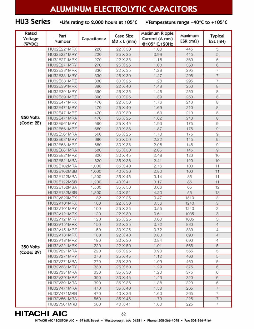
62
ALUMINUM ELECTROLYTIC CAPACITORSHU3 Series •Life rating to 2,000 hours at 105°C •Temperature range –40°C to +105°C
AIC
detaRegatloV)CDVW(
traPrebmuN
ecnaticapaCeziSesaC
)mm(LxDØ
elppiRmumixaMtnerruC A( smr )
zH021,C°501@
mumixaMm(RSE Ω)
lacipyT)Hn(LSE
XRM122E23UH 022 03X22 00.1 544 5YRM122E23UH 022 52X52 89.0 544 5XRM172E23UH 072 53X22 61.1 063 6YRM172E23UH 072 52X52 80.1 063 6XRM133E23UH 033 53X22 82.1 592 7YRM133E23UH 033 03X52 72.1 592 7ZRM133E23UH 033 52X03 82.1 592 7XRM193E23UH 093 04X22 84.1 052 8YRM193E23UH 093 53X52 64.1 052 8ZRM193E23UH 093 52X03 93.1 052 8XRM174E23UH 074 05X22 67.1 012 8YRM174E23UH 074 04X52 96.1 012 8ZRM174E23UH 074 03X03 36.1 012 8ARM174E23UH 074 52X53 26.1 012 8YRM165E23UH 065 54X52 39.1 571 9ZRM165E23UH 065 53X03 78.1 571 9ARM165E23UH 065 52X53 87.1 571 9YRM186E23UH 086 05X52 22.2 541 9ZRM186E23UH 086 53X03 60.2 541 9ARM186E23UH 086 03X53 60.2 541 9ZRM128E23UH 028 54X03 84.2 021 01ARM128E23UH 028 63X53 14.2 021 01ARM201E23UH 000,1 04X53 67.2 001 11BSM201E23UH 000,1 63X04 08.2 001 11ARM221E23UH 002,1 54X53 41.3 58 11BSM221E23UH 002,1 14X04 71.3 58 11ASM251E23UH 005,1 05X53 66.3 56 21BSM281E23UH 008,1 15X04 02.4 55 31XRM028V23UH 28 52X22 74.0 0151 3XRM101V23UH 001 03X22 65.0 0421 3YRM101V23UH 001 52X52 55.0 0421 3XRM121V23UH 021 03X22 16.0 5301 3YRM121V23UH 021 52X52 06.0 5301 3XRM151V23UH 051 53X22 27.0 038 4ZRM151V23UH 051 52X03 27.0 038 4XRM181V23UH 081 04X22 38.0 096 4ZRM181V23UH 081 03X03 48.0 096 4XRM122V23UH 022 05X22 10.1 565 5ARM122V23UH 022 52X53 39.0 565 5YRM172V23UH 072 54X52 21.1 064 5ARM172V23UH 072 03X53 90.1 064 5YRM133V23UH 033 05X52 92.1 573 6ARM133V23UH 033 03X53 02.1 573 6ZRM193V23UH 093 54X03 34.1 023 6ARM193V23UH 093 63X53 83.1 023 6ARM174V23UH 074 04X53 85.1 562 7BRM174V23UH 074 63X04 06.1 562 7ARM165V23UH 065 54X53 97.1 522 7BRM165V23UH 065 14X04 08.1 522 7
250 Volts(Code: 2E)
350 Volts(Code: 2V)
HITACHI AIC / BOSTON AIC • 69 Milk Street • Westborough, MA 01581 • Phone: 508-366-4092 • Fax: 508-366-9164
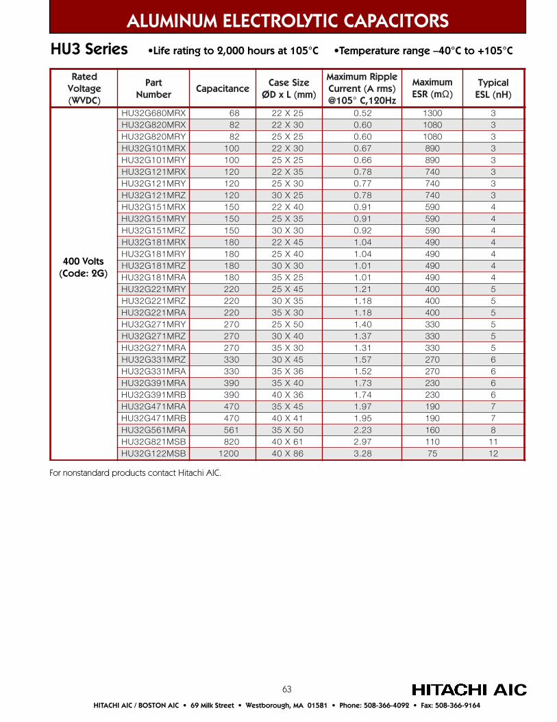
63
detaRegatloV)CDVW(
traPrebmuN
ecnaticapaCeziSesaC
)mm(LxDØ
elppiRmumixaMtnerruC A( smr )
zH021,C°501@
mumixaMm(RSE Ω)
lacipyT)Hn(LSE
XRM086G23UH 86 52X22 25.0 0031 3XRM028G23UH 28 03X22 06.0 0801 3YRM028G23UH 28 52X52 06.0 0801 3XRM101G23UH 001 03X22 76.0 098 3YRM101G23UH 001 52X52 66.0 098 3XRM121G23UH 021 53X22 87.0 047 3YRM121G23UH 021 03X52 77.0 047 3ZRM121G23UH 021 52X03 87.0 047 3XRM151G23UH 051 04X22 19.0 095 4YRM151G23UH 051 53X52 19.0 095 4ZRM151G23UH 051 03X03 29.0 095 4XRM181G23UH 081 54X22 40.1 094 4YRM181G23UH 081 04X52 40.1 094 4ZRM181G23UH 081 03X03 10.1 094 4ARM181G23UH 081 52X53 10.1 094 4YRM122G23UH 022 54X52 12.1 004 5ZRM122G23UH 022 53X03 81.1 004 5ARM122G23UH 022 03X53 81.1 004 5YRM172G23UH 072 05X52 04.1 033 5ZRM172G23UH 072 04X03 73.1 033 5ARM172G23UH 072 03X53 13.1 033 5ZRM133G23UH 033 54X03 75.1 072 6ARM133G23UH 033 63X53 25.1 072 6ARM193G23UH 093 04X53 37.1 032 6BRM193G23UH 093 63X04 47.1 032 6ARM174G23UH 074 54X53 79.1 091 7BRM174G23UH 074 14X04 59.1 091 7ARM165G23UH 165 05X53 32.2 061 8BSM128G23UH 028 16X04 79.2 011 11BSM221G23UH 0021 68X04 82.3 57 21
ALUMINUM ELECTROLYTIC CAPACITORSHU3 Series •Life rating to 2,000 hours at 105°C •Temperature range –40°C to +105°C
AICHITACHI AIC / BOSTON AIC • 69 Milk Street • Westborough, MA 01581 • Phone: 508-366-4092 • Fax: 508-366-9164
400 Volts(Code: 2G)
For nonstandard products contact Hitachi AIC.
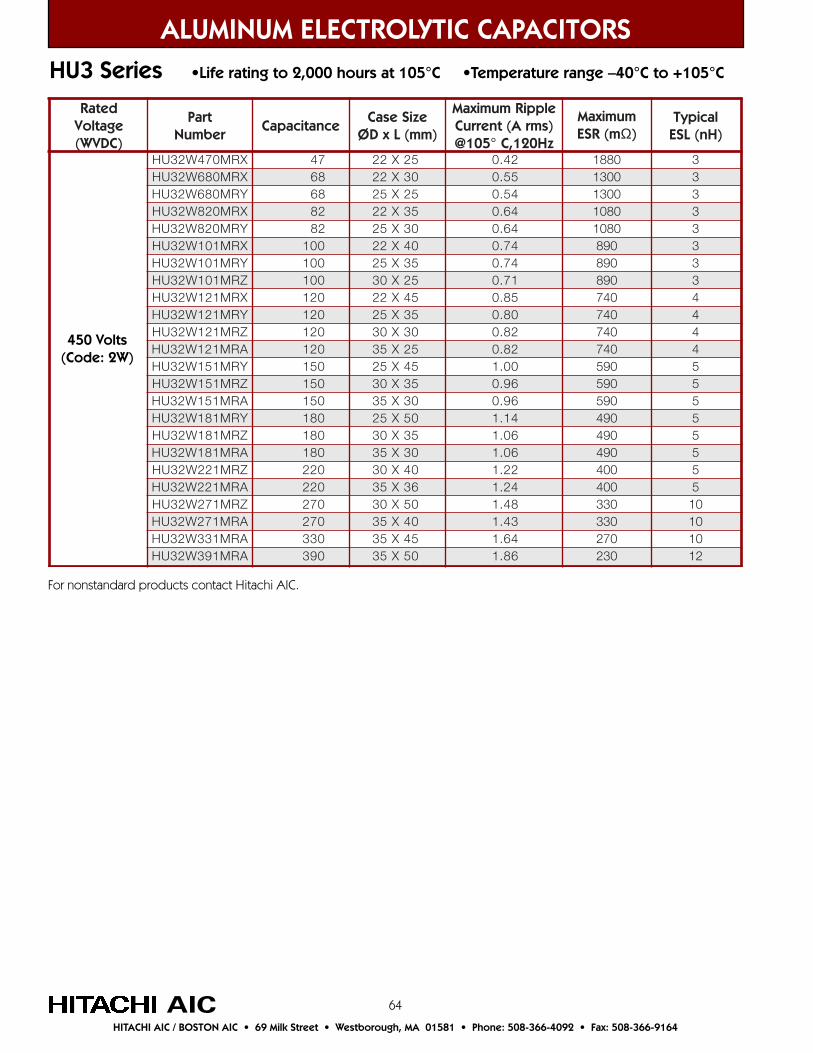
64AICHITACHI AIC / BOSTON AIC • 69 Milk Street • Westborough, MA 01581 • Phone: 508-366-4092 • Fax: 508-366-9164
ALUMINUM ELECTROLYTIC CAPACITORSHU3 Series •Life rating to 2,000 hours at 105°C •Temperature range –40°C to +105°C
450 Volts(Code: 2W)
For nonstandard products contact Hitachi AIC.
detaRegatloV)CDVW(
traPrebmuN
ecnaticapaCeziSesaC
)mm(LxDØ
elppiRmumixaMtnerruC A( smr )
zH021,C°501@
mumixaMm(RSE Ω)
lacipyT)Hn(LSE
XRM074W23UH 74 52X22 24.0 0881 3XRM086W23UH 86 03X22 55.0 0031 3YRM086W23UH 86 52X52 45.0 0031 3XRM028W23UH 28 53X22 46.0 0801 3YRM028W23UH 28 03X52 46.0 0801 3XRM101W23UH 001 04X22 47.0 098 3YRM101W23UH 001 53X52 47.0 098 3ZRM101W23UH 001 52X03 17.0 098 3XRM121W23UH 021 54X22 58.0 047 4YRM121W23UH 021 53X52 08.0 047 4ZRM121W23UH 021 03X03 28.0 047 4ARM121W23UH 021 52X53 28.0 047 4YRM151W23UH 051 54X52 00.1 095 5ZRM151W23UH 051 53X03 69.0 095 5ARM151W23UH 051 03X53 69.0 095 5YRM181W23UH 081 05X52 41.1 094 5ZRM181W23UH 081 53X03 60.1 094 5ARM181W23UH 081 03X53 60.1 094 5ZRM122W23UH 022 04X03 22.1 004 5ARM122W23UH 022 63X53 42.1 004 5ZRM172W23UH 072 05X03 84.1 033 01ARM172W23UH 072 04X53 34.1 033 01ARM133W23UH 033 54X53 46.1 072 01ARM193W23UH 093 05X53 68.1 032 21
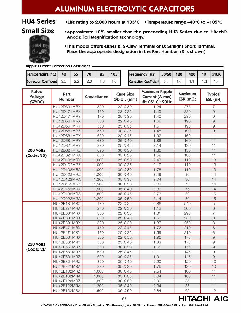
65
detaRegatloV)CDVW(
traPrebmuN
ecnaticapaCeziSesaC
)mm(LxDØ
elppiRmumixaMtnerruC )smrA(
zH021,C°501@
mumixaMm(RSE Ω)
lacipyT)Hn(LSE
XRM193D24UH 093 03X22 42.1 572 7XRM174D24UH 074 53X22 54.1 032 9YRM174D24UH 074 03X52 04.1 032 9XRM165D24UH 065 04X22 66.1 091 9YRM165D24UH 065 53X52 16.1 091 9ZRM165D24UH 065 52X03 54.1 091 9XRM186D24UH 086 54X22 29.1 061 11YRM186D24UH 086 04X52 68.1 061 11YRM128D24UH 028 54X52 41.2 031 11ZRM128D24UH 028 03X03 68.1 031 11ARM128D24UH 028 52X53 25.1 031 11YRM201D24UH 000,1 05X52 74.2 011 31ZRM201D24UH 000,1 53X03 71.2 011 31ARM201D24UH 000,1 03X53 87.1 011 31ZRM221D24UH 002,1 04X03 94.2 09 41ARM221D24UH 002,1 53X53 40.2 09 41ZRM251D24UH 005,1 05X03 30.3 57 41ARM251D24UH 005,1 04X53 93.2 57 41ARM281D24UH 008,1 54X53 37.2 06 51ARM222D24UH 002,2 05X53 41.3 05 51XRM181E24UH 081 52X22 68.0 045 5XRM172E24UH 072 03X22 21.1 063 6XRM133E24UH 033 53X22 13.1 592 7XRM193E24UH 093 04X22 05.1 052 8YRM193E24UH 093 03X52 73.1 052 8XRM174E24UH 074 54X22 27.1 012 8YRM174E24UH 074 53X52 95.1 012 8XRM165E24UH 065 05X22 69.1 571 9YRM165E24UH 065 04X52 38.1 571 9ZRM165E24UH 065 03X03 56.1 571 9YRM186E24UH 086 54X52 11.2 541 9ZRM186E24UH 086 53X03 19.1 541 9ZRM128E24UH 028 04X03 02.2 021 01ARM128E24UH 028 03X53 67.1 021 01ZRM201E24UH 000,1 54X03 45.2 001 11ARM201E24UH 000,1 53X53 40.2 001 11ZRM221E24UH 002,1 05X03 09.2 58 11ARM221E24UH 002,1 04X53 43.2 58 11ARM251E24UH 005,1 05X53 48.2 56 21
ALUMINUM ELECTROLYTIC CAPACITORS
250 Volts(Code: 2E)
200 Volts(Code: 2D)
HU4 Series •Life rating to 2,000 hours at 105°C •Temperature range –40°C to +105°C
Small Size •Approximate 10% smaller than the preceeding HU3 Series due to Hitachi’s Anode Foil Magnification technology.
•This model offers either R: 2-Claw Terminal or U: Straight Short Terminal. Place the appropriate designation in the Part Number. (R is shown)
AIC
Frequency (Hz) 50/60 120 400 1K ≥10K
Correction Coefficient 0.8 1.0 1.1 1.3 1.4
Temperature (°C) 40 55 70 85 105
Correction Coefficient 2.5 2.2 2.0 1.8 1.0
Ripple Current Correction Coefficient
HITACHI AIC / BOSTON AIC • 69 Milk Street • Westborough, MA 01581 • Phone: 508-366-4092 • Fax: 508-366-9164
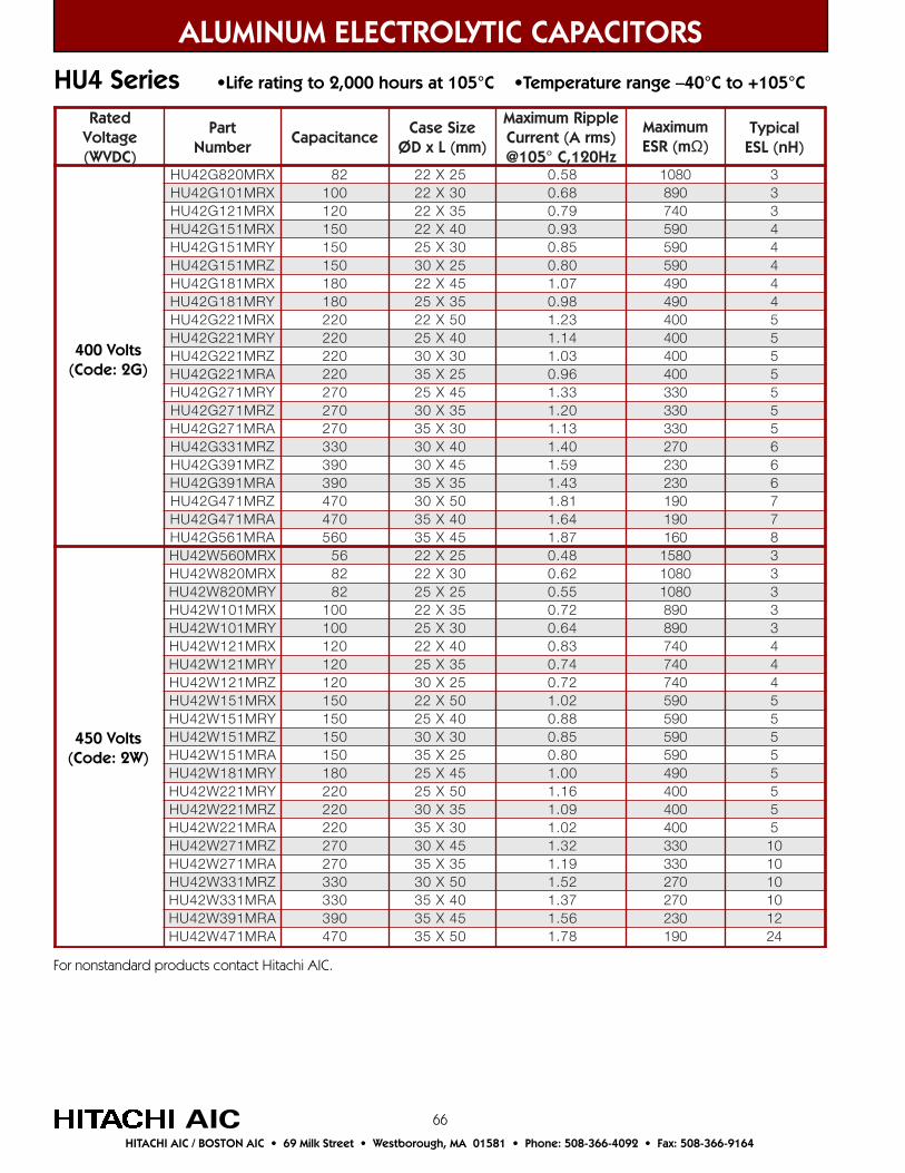
66AICHITACHI AIC / BOSTON AIC • 69 Milk Street • Westborough, MA 01581 • Phone: 508-366-4092 • Fax: 508-366-9164
ALUMINUM ELECTROLYTIC CAPACITORS
HU4 Series •Life rating to 2,000 hours at 105°C •Temperature range –40°C to +105°C
detaRegatloV)CDVW(
traPrebmuN
ecnaticapaCeziSesaC
)mm(LxDØ
elppiRmumixaM)smrA(tnerruCzH021,C°501@
mumixaMm(RSE Ω)
lacipyT)Hn(LSE
XRM028G24UH 28 52X22 85.0 0801 3XRM101G24UH 001 03X22 86.0 098 3XRM121G24UH 021 53X22 97.0 047 3XRM151G24UH 051 04X22 39.0 095 4YRM151G24UH 051 03X52 58.0 095 4ZRM151G24UH 051 52X03 08.0 095 4XRM181G24UH 081 54X22 70.1 094 4YRM181G24UH 081 53X52 89.0 094 4XRM122G24UH 022 05X22 32.1 004 5YRM122G24UH 022 04X52 41.1 004 5ZRM122G24UH 022 03X03 30.1 004 5ARM122G24UH 022 52X53 69.0 004 5YRM172G24UH 072 54X52 33.1 033 5ZRM172G24UH 072 53X03 02.1 033 5ARM172G24UH 072 03X53 31.1 033 5ZRM133G24UH 033 04X03 04.1 072 6ZRM193G24UH 093 54X03 95.1 032 6ARM193G24UH 093 53X53 34.1 032 6ZRM174G24UH 074 05X03 18.1 091 7ARM174G24UH 074 04X53 46.1 091 7ARM165G24UH 065 54X53 78.1 061 8XRM065W24UH 65 52X22 84.0 0851 3XRM028W24UH 28 03X22 26.0 0801 3YRM028W24UH 28 52X52 55.0 0801 3XRM101W24UH 001 53X22 27.0 098 3YRM101W24UH 001 03X52 46.0 098 3XRM121W24UH 021 04X22 38.0 047 4YRM121W24UH 021 53X52 47.0 047 4ZRM121W24UH 021 52X03 27.0 047 4XRM151W24UH 051 05X22 20.1 095 5YRM151W24UH 051 04X52 88.0 095 5ZRM151W24UH 051 03X03 58.0 095 5ARM151W24UH 051 52X53 08.0 095 5YRM181W24UH 081 54X52 00.1 094 5YRM122W24UH 022 05X52 61.1 004 5ZRM122W24UH 022 53X03 90.1 004 5ARM122W24UH 022 03X53 20.1 004 5ZRM172W24UH 072 54X03 23.1 033 01ARM172W24UH 072 53X53 91.1 033 01ZRM133W24UH 033 05X03 25.1 072 01ARM133W24UH 033 04X53 73.1 072 01ARM193W24UH 093 54X53 65.1 032 21ARM174W24UH 074 05X53 87.1 091 42
400 Volts(Code: 2G)
450 Volts(Code: 2W)
For nonstandard products contact Hitachi AIC.
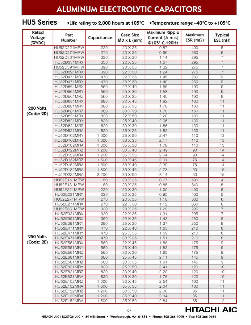
67
detaRegatloV)CDVW(
traPrebmuN
ecnaticapaCeziSesaC
)mm(LxDØ
elppiRmumixaMtnerruC )smrA(
zH021,C°501@
mumixaMm(RSE Ω)
lacipyT)Hn(LSE
WRM122D25UH 022 52X02 78.0 004 5WRM172D25UH 072 52X02 69.0 063 6WRM133D25UH 033 03X02 41.1 592 7XRM133D25UH 033 52X22 70.1 592 7WRM193D25UH 093 53X02 23.1 572 7XRM193D25UH 093 03X22 42.1 572 7XRM174D25UH 074 53X22 54.1 032 9YRM174D25UH 074 03X52 04.1 032 9XRM165D25UH 065 04X22 66.1 091 9YRM165D25UH 065 03X52 35.1 091 9ZRM165D25UH 065 52X03 54.1 091 9XRM186D25UH 086 54X22 29.1 061 11YRM186D25UH 086 53X52 87.1 061 11ZRM186D25UH 086 03X03 07.1 061 11XRM128D25UH 028 05X22 02.2 031 11YRM128D25UH 028 04X52 60.2 031 11ZRM128D25UH 028 03X03 68.1 031 11ARM128D25UH 028 52X53 25.1 031 11YRM201D25UH 000,1 05X52 74.2 011 31ZRM201D25UH 000,1 53X03 71.2 011 31ARM201D25UH 000,1 03X53 87.1 011 31ZRM221D25UH 002,1 04X03 94.2 09 41ARM221D25UH 002,1 53X53 40.2 09 41ZRM251D25UH 005,1 54X03 19.2 57 41ARM251D25UH 005,1 04X53 93.2 57 41ARM281D25UH 008,1 54X53 37.2 06 51ARM222D25UH 002,2 05X53 41.3 05 51WRM151E25UH 051 52X02 77.0 095 4WRM181E25UH 081 52X02 58.0 045 5WRM122E25UH 022 03X02 00.1 004 5XRM122E25UH 022 52X22 59.0 004 5WRM172E25UH 072 53X02 81.1 063 6XRM172E25UH 072 03X22 21.1 063 6WRM133E25UH 033 53X02 92.1 592 7XRM133E25UH 033 53X22 13.1 592 7XRM193E25UH 093 53X22 34.1 052 8YRM193E25UH 093 03X52 73.1 052 8XRM174E25UH 074 04X22 56.1 012 8YRM174E25UH 074 53X52 95.1 012 8ZRM174E25UH 074 52X03 15.1 012 8XRM165E25UH 065 54X22 88.1 571 9YRM165E25UH 065 04X52 38.1 571 9ZRM165E25UH 065 03X03 56.1 571 9YRM186E25UH 086 54X52 11.2 541 9ZRM186E25UH 086 53X03 19.1 541 9YRM128E25UH 028 05X52 14.2 021 01ZRM128E25UH 028 04X03 02.2 021 01ARM128E25UH 028 03X53 67.1 021 01ZRM201E25UH 000,1 54X03 45.2 001 11ARM201E25UH 000,1 53X53 40.2 001 11ZRM221E25UH 002,1 05X03 09.2 58 11ARM221E25UH 002,1 04X53 43.2 58 11ARM251E25UH 005,1 05X53 48.2 56 21
ALUMINUM ELECTROLYTIC CAPACITORSHU5 Series •Life rating to 2,000 hours at 105°C •Temperature range –40°C to +105°C
HITACHI AIC / BOSTON AIC • 69 Milk Street • Westborough, MA 01581 • Phone: 508-366-4092 • Fax: 508-366-9164
AIC
200 Volts(Code: 2D)
250 Volts(Code: 2E)

68
ALUMINUM ELECTROLYTIC CAPACITORSHU5 Series •Life rating to 2,000 hours at 105°C •Temperature range –40°C to +105°C
AICHITACHI AIC / BOSTON AIC • 69 Milk Street • Westborough, MA 01581 • Phone: 508-366-4092 • Fax: 508-366-9164
detaRegatloV)CDVW(
traPrebmuN
ecnaticapaCeziSesaC
)mm(LxDØ
elppiRmumixaM)smrA(tnerruCzH021,C°501@
mumixaMm(RSE Ω)
lacipyT)Hn(LSE
WRM065G25UH 65 52X02 74.0 0851 3WRM086G25UH 86 52X02 25.0 0031 3WRM028G25UH 28 03X02 16.0 0801 3XRM028G25UH 28 52X22 85.0 0801 3WRM101G25UH 001 03X02 76.0 098 3XRM101G25UH 001 03X22 86.0 098 3WRM121G25UH 021 53X02 87.0 047 3XRM121G25UH 021 03X22 47.0 047 3XRM151G25UH 051 53X22 88.0 095 4YRM151G25UH 051 03X52 58.0 095 4ZRM151G25UH 051 52X03 08.0 095 4XRM181G25UH 081 04X22 20.1 094 4YRM181G25UH 081 53X52 89.0 094 4ZRM181G25UH 081 52X03 88.0 094 4XRM122G25UH 022 54X22 71.1 004 5YRM122G25UH 022 04X52 41.1 004 5ZRM122G25UH 022 03X03 30.1 004 5ARM122G25UH 022 52X53 69.0 004 5YRM172G25UH 072 54X52 33.1 033 5ZRM172G25UH 072 53X03 02.1 033 5ARM172G25UH 072 03X53 31.1 033 5YRM133G25UH 033 05X52 35.1 072 6ZRM133G25UH 033 04X03 04.1 072 6ARM133G25UH 033 03X53 52.1 072 6ZRM193G25UH 093 54X03 95.1 032 6ARM193G25UH 093 53X53 34.1 032 6ZRM174G25UH 074 05X03 18.1 091 7ARM174G25UH 074 04X53 46.1 091 7ARM165G25UH 065 54X53 78.1 061 8ARM186G25UH 086 05X53 31.2 541 9
WRM065V0245UH 65 52X02 74.0 0851 3WRM086V0245UH 86 03X02 65.0 0031 3XRM086V0245UH 86 52X22 25.0 0031 3WRM028V0245UH 28 03X02 16.0 0801 3WRM101V0245UH 001 53X02 27.0 098 3XRM101V0245UH 001 03X22 76.0 098 3XRM121V0245UH 021 53X22 87.0 047 3XRM151V0245UH 051 04X22 29.0 095 4XRM181V0245UH 081 54X22 60.1 094 4YRM122V0245UH 022 54X52 11.1 004 5YRM172V0245UH 072 05X52 92.1 033 5ARM172V0245UH 072 03X53 31.1 033 5ZRM133V0245UH 033 54X03 64.1 072 6ARM133V0245UH 033 53X53 23.1 072 6ZRM193V0245UH 093 05X03 66.1 032 6ARM193V0245UH 093 04X53 05.1 032 6ARM174v0245UH 074 54X53 17.1 091 7ARM165v0245UH 165 05X53 49.1 061 8
400 Volts(Code: 2G)
420 Volts(Code: 420V)
NEW
VOLTAGE
RATING
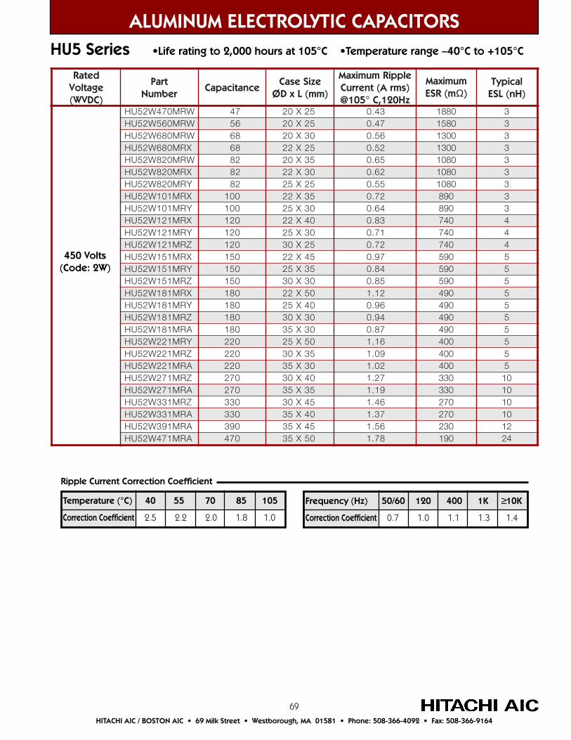
69
ALUMINUM ELECTROLYTIC CAPACITORSHU5 Series •Life rating to 2,000 hours at 105°C •Temperature range –40°C to +105°C
AICHITACHI AIC / BOSTON AIC • 69 Milk Street • Westborough, MA 01581 • Phone: 508-366-4092 • Fax: 508-366-9164
Frequency (Hz) 50/60 120 400 1K ≥10K
Correction Coefficient 0.7 1.0 1.1 1.3 1.4
Temperature (°C) 40 55 70 85 105
Correction Coefficient 2.5 2.2 2.0 1.8 1.0
Ripple Current Correction Coefficient
detaRegatloV)CDVW(
traPrebmuN
ecnaticapaCeziSesaC
)mm(LxDØ
elppiRmumixaM)smrA(tnerruCzH021,C°501@
mumixaMm(RSE Ω)
lacipyT)Hn(LSE
WRM074W25UH 74 52X02 34.0 0881 3WRM065W25UH 65 52X02 74.0 0851 3WRM086W25UH 86 03X02 65.0 0031 3XRM086W25UH 86 52X22 25.0 0031 3WRM028W25UH 28 53X02 56.0 0801 3XRM028W25UH 28 03X22 26.0 0801 3YRM028W25UH 28 52X52 55.0 0801 3XRM101W25UH 001 53X22 27.0 098 3YRM101W25UH 001 03X52 46.0 098 3XRM121W25UH 021 04X22 38.0 047 4YRM121W25UH 021 03X52 17.0 047 4ZRM121W25UH 021 52X03 27.0 047 4XRM151W25UH 051 54X22 79.0 095 5YRM151W25UH 051 53X52 48.0 095 5ZRM151W25UH 051 03X03 58.0 095 5XRM181W25UH 081 05X22 21.1 094 5YRM181W25UH 081 04X52 69.0 094 5ZRM181W25UH 081 03X03 49.0 094 5ARM181W25UH 081 03X53 78.0 094 5YRM122W25UH 022 05X52 61.1 004 5ZRM122W25UH 022 53X03 90.1 004 5ARM122W25UH 022 03X53 20.1 004 5ZRM172W25UH 072 04X03 72.1 033 01ARM172W25UH 072 53X53 91.1 033 01ZRM133W25UH 033 54X03 64.1 072 01ARM133W25UH 033 04X53 73.1 072 01ARM193W25UH 093 54X53 65.1 032 21ARM174W25UH 074 05X53 87.1 091 42
450 Volts(Code: 2W)
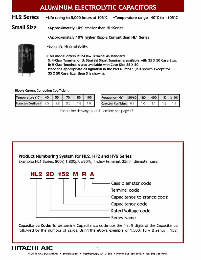
70
•Long life, High reliability.
•This model offers R: 2-Claw Terminal as standard. S: 4-Claw Terminal or U: Straight Short Terminal is available with 35 X 50 Case Size. R: 2-Claw Terminal is also available with Case Size 35 X 50. Place the appropriate designation in the Part Number. (R is shown except for 35 X 50 Case Size, then S is shown).
ALUMINUM ELECTROLYTIC CAPACITORSHL2 Series •Life rating to 5,000 hours at 105°C •Temperature range –40°C to +105°C
•Approximately 10% smaller than HL1Series.
•Approximately 10% higher Ripple Current than HL1 Series.
AIC
Product Numbering System for HL2, HF2 and HV2 SeriesExample: HL1 Series, 200V, 1,800µF, ±20%, 4-claw terminal, 35mm diameter case
Case diameter code
Terminal code
Capacitance tolerance code
Capacitance code
Rated Voltage code
Series Name
HL2 2D 152 M R A
Capacitance Code: To determine Capacitance code use the first 2 digits of the Capacitancefollowed by the number of zeros. Using the above example of 1,500: 15 + 2 zeros = 152.
For outline drawings and dimensions see page 47.
HITACHI AIC / BOSTON AIC • 69 Milk Street • Westborough, MA 01581 • Phone: 508-366-4092 • Fax: 508-366-9164
Frequency (Hz) 50/60 120 400 1K ≥10K
Correction Coefficient 0.7 1.0 1.1 1.3 1.4
Temperature (°C) 40 55 70 85 105
Correction Coefficient 2.5 2.2 2.0 1.8 1.0
Ripple Current Correction Coefficient
Small Size

71
ALUMINUM ELECTROLYTIC CAPACITORS
AICHITACHI AIC / BOSTON AIC • 69 Milk Street • Westborough, MA 01581 • Phone: 508-366-4092 • Fax: 508-366-9164
detaRegatloV)CDVW(
traPrebmuN
ecnaticapaCeziSesaC
)mm(LxDØ
elppiRmumixaMtnerruC A( smr )
zH021,C°501@
mumixaMm(RSE Ω)
lacipyT)Hn(LSE
WRM122D22LH 022 52X02 88.0 654 5WRM172D22LH 072 03X02 50.1 273 6WRM133D22LH 033 53X02 32.1 403 7XRM133D22LH 033 03X22 91.1 403 7YRM133D22LH 033 52X52 41.1 403 7YRM193D22LH 093 03X52 23.1 752 7XRM174D22LH 074 04X22 85.1 412 9YRM174D22LH 074 03X52 54.1 412 9ZRM174D22LH 074 52X03 24.1 412 9XRM165D22LH 065 54X22 18.1 971 9YRM165D22LH 065 53X52 76.1 971 9YRM186D22LH 086 04X52 39.1 841 11ZRM186D22LH 086 03X03 18.1 841 11YRM128D22LH 028 54X52 22.2 221 11ZRM128D22LH 028 53X03 01.2 221 11ZRM201D22LH 0001 04X03 34.2 001 31ARM201D22LH 0001 03X53 50.2 001 31ZRM221D22LH 0021 54X03 87.2 48 41ARM221D22LH 0021 53X53 63.2 48 41ARM251D22LH 0051 04X53 67.2 76 41WRM151E22LH 051 52X02 37.0 694 5WRM181E22LH 081 03X02 58.0 314 5XRM181E22LH 081 52X22 28.0 314 5WRM122E22LH 022 03X02 49.0 833 6WRM172E22LH 072 53X02 11.1 572 7YRM172E22LH 072 52X52 30.1 572 7XRM133E22LH 033 53X22 62.1 522 8YRM133E22LH 033 03X52 12.1 522 8XRM193E22LH 093 04X22 44.1 191 8YRM193E22LH 093 53X52 93.1 191 8ZRM193E22LH 093 52X03 03.1 191 8XRM174E22LH 074 05X22 37.1 261 9YRM174E22LH 074 04X52 16.1 261 9ZRM174E22LH 074 03X03 15.1 261 9YRM165E22LH 065 54X52 48.1 631 9YRM186E22LH 086 05X52 11.2 211 01ZRM186E22LH 086 53X03 19.1 211 01ZRM128E22LH 028 04X03 02.2 39 11ZRM201E22LH 0001 05X03 46.2 67 11ARM221E22LH 0021 54X53 75.2 46 21ARM251E22LH 0051 05X53 99.2 16 31
200 Volts(Code: 2D)
250 Volts(Code: 2E)
HL2 Series •Life rating to 5,000 hours at 105°C•Temperature range –40°C to +105°C
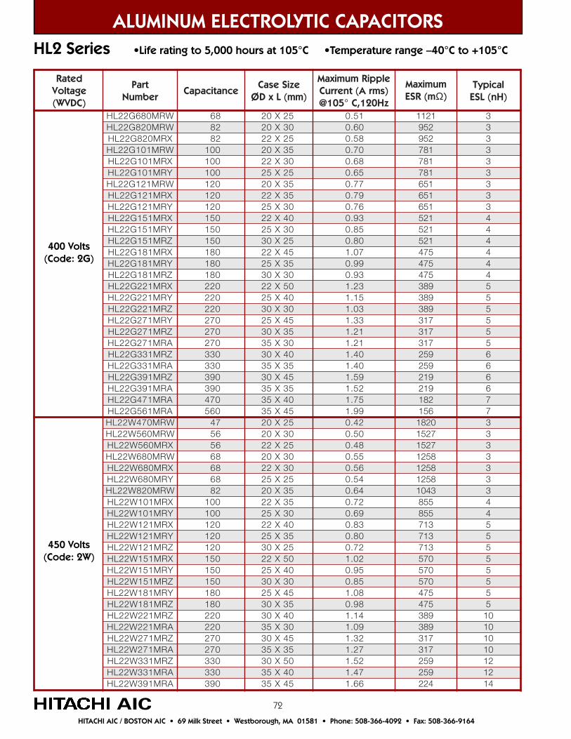
72
ALUMINUM ELECTROLYTIC CAPACITORSHL2 Series •Life rating to 5,000 hours at 105°C •Temperature range –40°C to +105°C
detaRegatloV)CDVW(
traPrebmuN
ecnaticapaCeziSesaC
)mm(LxDØ
elppiRmumixaMtnerruC A( smr )
zH021,C°501@
mumixaMm(RSE Ω)
lacipyT)Hn(LSE
WRM086G22LH 86 52X02 15.0 1211 3WRM028G22LH 28 03X02 06.0 259 3XRM028G22LH 28 52X22 85.0 259 3WRM101G22LH 001 53X02 07.0 187 3XRM101G22LH 001 03X22 86.0 187 3YRM101G22LH 001 52X52 56.0 187 3WRM121G22LH 021 53X02 77.0 156 3XRM121G22LH 021 53X22 97.0 156 3YRM121G22LH 021 03X52 67.0 156 3XRM151G22LH 051 04X22 39.0 125 4YRM151G22LH 051 03X52 58.0 125 4ZRM151G22LH 051 52X03 08.0 125 4XRM181G22LH 081 54X22 70.1 574 4YRM181G22LH 081 53X52 99.0 574 4ZRM181G22LH 081 03X03 39.0 574 4XRM122G22LH 022 05X22 32.1 983 5YRM122G22LH 022 04X52 51.1 983 5ZRM122G22LH 022 03X03 30.1 983 5YRM172G22LH 072 54X52 33.1 713 5ZRM172G22LH 072 53X03 12.1 713 5ARM172G22LH 072 03X53 12.1 713 5ZRM133G22LH 033 04X03 04.1 952 6ARM133G22LH 033 53X53 04.1 952 6ZRM193G22LH 093 54X03 95.1 912 6ARM193G22LH 093 53X53 25.1 912 6ARM174G22LH 074 04X53 57.1 281 7ARM165G22LH 065 54X53 99.1 651 7WRM074W22LH 74 52X02 24.0 0281 3WRM065W22LH 65 03X02 05.0 7251 3XRM065W22LH 65 52X22 84.0 7251 3WRM086W22LH 86 03X02 55.0 8521 3XRM086W22LH 86 03X22 65.0 8521 3YRM086W22LH 86 52X52 45.0 8521 3WRM028W22LH 28 53X02 46.0 3401 3XRM101W22LH 001 53X22 27.0 558 4YRM101W22LH 001 03X52 96.0 558 4XRM121W22LH 021 04X22 38.0 317 5YRM121W22LH 021 53X52 08.0 317 5ZRM121W22LH 021 52X03 27.0 317 5XRM151W22LH 051 05X22 20.1 075 5YRM151W22LH 051 04X52 59.0 075 5ZRM151W22LH 051 03X03 58.0 075 5YRM181W22LH 081 54X52 80.1 574 5ZRM181W22LH 081 53X03 89.0 574 5ZRM122W22LH 022 04X03 41.1 983 01ARM122W22LH 022 03X53 90.1 983 01ZRM172W22LH 072 54X03 23.1 713 01ARM172W22LH 072 53X53 72.1 713 01ZRM133W22LH 033 05X03 25.1 952 21ARM133W22LH 033 04X53 74.1 952 21ARM193W22LH 093 54X53 66.1 422 41
400 Volts(Code: 2G)
450 Volts(Code: 2W)
AICHITACHI AIC / BOSTON AIC • 69 Milk Street • Westborough, MA 01581 • Phone: 508-366-4092 • Fax: 508-366-9164
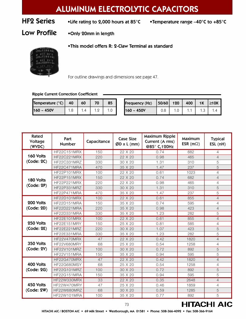
73 AICHITACHI AIC / BOSTON AIC • 69 Milk Street • Westborough, MA 01581 • Phone: 508-366-4092 • Fax: 508-366-9164
ALUMINUM ELECTROLYTIC CAPACITORSHF2 Series •Life rating to 2,000 hours at 85°C •Temperature range –40°C to +85°C
detaRegatloV)CDVW(
traPrebmuN
ecnaticapaCeziSesaC
)mm(LxDØ
elppiRmumixaMtnerruC A( smr )
zH021,C°58@
mumixaMm(RSE Ω)
lacipyT)Hn(LSE
XRM151C22FH 051 02X22 47.0 286 4XRM122C22FH 022 02X22 89.0 564 4ZRM133C22FH 033 02X03 13.1 013 5ARM174C22FH 074 02X53 74.1 732 5XRM101P22FH 001 02X22 16.0 3201 4XRM151P22FH 051 02X22 47.0 286 4XRM122P22FH 022 02X22 89.0 564 4ZRM133P22FH 033 02X03 13.1 013 5ARM174P22FH 074 02X53 74.1 732 5XRM101D22FH 001 02X22 16.0 558 4ARM151D22FH 051 02X53 47.0 595 4ARM122D22FH 022 02X53 89.0 324 4ARM133D22FH 033 02X53 32.1 282 5XRM101E22FH 001 02X22 16.0 558 4YRM151E22FH 051 02X52 18.0 585 4ZRM122E22FH 022 02X03 70.1 324 5ARM133E22FH 033 02X53 32.1 282 5XRM074V22FH 74 02X22 24.0 0281 4YRM086V22FH 86 02X52 45.0 8521 4ZRM101V22FH 001 02X03 27.0 298 5ARM151V22FH 051 02X53 49.0 595 5XRM074G22FH 74 02X22 24.0 0281 4YSM086G22FH 86 02X52 45.0 8521 4ZRM101G22FH 001 02X03 27.0 298 5ARM151G22FH 051 02X53 49.0 595 5XRM033W22FH 33 02X22 53.0 8462 4YRM074W22FH 74 02X52 64.0 9581 4ZRM086W22FH 86 02X03 95.0 5821 5ARM101W22FH 001 02X53 77.0 298 5
350 Volts(Code: 2V)
250 Volts(Code: 2E)
200 Volts(Code: 2D)
180 Volts(Code: 2P)
160 Volts(Code: 2C)
450 Volts(Code: 2W)
400 Volts(Code: 2G)
Low Profile •Only 20mm in length
•This model offers R: 2-Claw Terminal as standard
Ripple Current Correction Coefficient
Frequency (Hz) 50/60 120 400 1K ≥10K
160 ~ 450V 0.8 1.0 1.1 1.3 1.4
Temperature (°C) 40 60 70 85
160 ~ 450V 1.8 1.4 1.2 1.0
For outline drawings and dimensions see page 47.
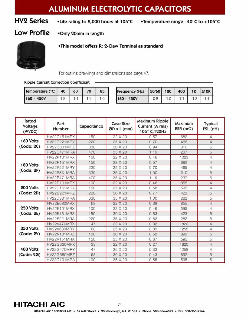
74AIC
ALUMINUM ELECTROLYTIC CAPACITORSHV2 Series •Life rating to 2,000 hours at 105°C •Temperature range –40°C to +105°C
detaRegatloV)CDVW(
traPrebmuN
ecnaticapaCeziSesaC
)mm(LxDØ
elppiRmumixaMtnerruC A( smr )
zH021,C°501
mumixaMm(RSE Ω)
lacipyT)Hn(LSE
XRM151C22VH 051 02X22 75.0 286 4YRM122C22VH 022 02X52 07.0 564 4ZRM133C22VH 033 02X03 49.0 013 5ARM174C22VH 074 02X53 91.1 732 5XRM101P22VH 001 02X22 64.0 3201 4XRM151P22VH 051 02X22 75.0 286 4YRM122P22VH 022 02X52 07.0 564 4ARM133P22VH 033 02X53 00.1 013 5ARM174P22VH 074 02X53 91.1 732 5XRM101D22VH 001 02X22 64.0 558 4YRM151D22VH 051 02X52 85.0 595 4ZRM122D22VH 022 02X03 77.0 324 5ARM133D22VH 033 02X53 00.1 282 5XRM086E22VH 86 02X22 83.0 558 4XRM101E22VH 001 02X22 64.0 595 4ZRM151E22VH 051 02X03 36.0 324 5ARM122E22VH 022 02X53 28.0 282 5XRM074V22VH 74 02X22 23.0 0281 4YRM086V22VH 86 02X52 93.0 8521 4ZRM101V22VH 001 02X03 25.0 298 5ARM151V22VH 051 02X53 76.0 595 5XRM033G22VH 33 02X22 72.0 0281 4YRM074G22VH 74 02X52 33.0 8521 4ZRM086G22VH 86 02X03 34.0 298 5ARM101G22VH 001 02X53 55.0 595 5
350 Volts(Code: 2V)
250 Volts(Code: 2E)
200 Volts(Code: 2D)
180 Volts(Code: 2P)
160 Volts(Code: 2C)
400 Volts(Code: 2G)
Ripple Current Correction Coefficient
Frequency (Hz) 50/60 120 400 1K ≥10K
160 ~ 450V 0.8 1.0 1.1 1.3 1.4
Temperature (°C) 40 60 70 85
160 ~ 450V 1.8 1.4 1.2 1.0
Low Profile •Only 20mm in length
•This model offers R: 2-Claw Terminal as standard
For outline drawings and dimensions see page 47.
HITACHI AIC / BOSTON AIC • 69 Milk Street • Westborough, MA 01581 • Phone: 508-366-4092 • Fax: 508-366-9164
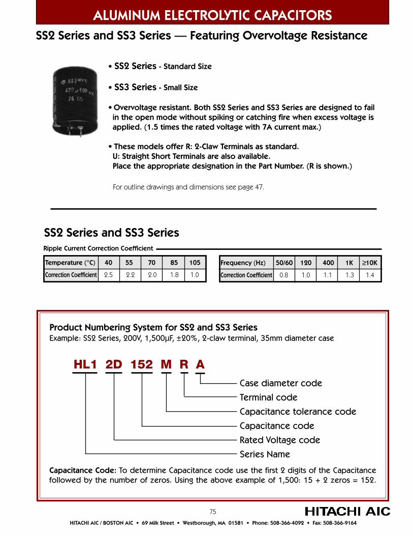
75 AICHITACHI AIC / BOSTON AIC • 69 Milk Street • Westborough, MA 01581 • Phone: 508-366-4092 • Fax: 508-366-9164
ALUMINUM ELECTROLYTIC CAPACITORS
Frequency (Hz) 50/60 120 400 1K ≥10K
Correction Coefficient 0.8 1.0 1.1 1.3 1.4
Temperature (°C) 40 55 70 85 105
Correction Coefficient 2.5 2.2 2.0 1.8 1.0
Ripple Current Correction Coefficient
SS2 Series and SS3 Series
• SS2 Series - Standard Size
• SS3 Series - Small Size
• Overvoltage resistant. Both SS2 Series and SS3 Series are designed to fail in the open mode without spiking or catching fire when excess voltage is applied. (1.5 times the rated voltage with 7A current max.)
• These models offer R: 2-Claw Terminals as standard. U: Straight Short Terminals are also available. Place the appropriate designation in the Part Number. (R is shown.)
SS2 Series and SS3 Series — Featuring Overvoltage Resistance
For outline drawings and dimensions see page 47.
Product Numbering System for SS2 and SS3 SeriesExample: SS2 Series, 200V, 1,500µF, ±20%, 2-claw terminal, 35mm diameter case
Case diameter code
Terminal code
Capacitance tolerance code
Capacitance code
Rated Voltage code
Series Name
HL1 2D 152 M R A
Capacitance Code: To determine Capacitance code use the first 2 digits of the Capacitancefollowed by the number of zeros. Using the above example of 1,500: 15 + 2 zeros = 152.
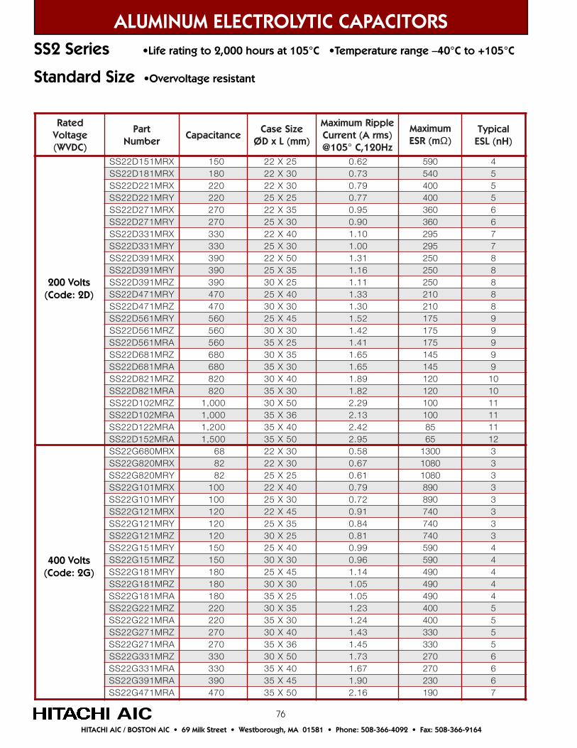
76
ALUMINUM ELECTROLYTIC CAPACITORS
HITACHI AIC / BOSTON AIC • 69 Milk Street • Westborough, MA 01581 • Phone: 508-366-4092 • Fax: 508-366-9164
SS2 Series •Life rating to 2,000 hours at 105°C •Temperature range –40°C to +105°C
detaRegatloV)CDVW(
traPrebmuN
ecnaticapaCeziSesaC
)mm(LxDØ
elppiRmumixaMtnerruC A( smr )
zH021,C°501@
mumixaMm(RSE Ω)
lacipyT)Hn(LSE
XRM151D22SS 051 52X22 26.0 095 4XRM181D22SS 081 03X22 37.0 045 5XRM122D22SS 022 03X22 97.0 004 5YRM122D22SS 022 52X52 77.0 004 5XRM172D22SS 072 53X22 59.0 063 6YRM172D22SS 072 03X52 09.0 063 6XRM133D22SS 033 04X22 01.1 592 7YRM133D22SS 033 03X52 00.1 592 7XRM193D22SS 093 05X22 13.1 052 8YRM193D22SS 093 53X52 61.1 052 8ZRM193D22SS 093 52X03 11.1 052 8YRM174D22SS 074 04X52 33.1 012 8ZRM174D22SS 074 03X03 03.1 012 8YRM165D22SS 065 54X52 25.1 571 9ZRM165D22SS 065 03X03 24.1 571 9ARM165D22SS 065 52X53 14.1 571 9ZRM186D22SS 086 53X03 56.1 541 9ARM186D22SS 086 03X53 56.1 541 9ZRM128D22SS 028 04X03 98.1 021 01ARM128D22SS 028 03X53 28.1 021 01ZRM201D22SS 000,1 05X03 92.2 001 11ARM201D22SS 000,1 63X53 31.2 001 11ARM221D22SS 002,1 04X53 24.2 58 11ARM251D22SS 005,1 05X53 59.2 56 21XRM086G22SS 86 03X22 85.0 0031 3XRM028G22SS 28 03X22 76.0 0801 3YRM028G22SS 28 52X52 16.0 0801 3XRM101G22SS 001 04X22 97.0 098 3YRM101G22SS 001 03X52 27.0 098 3XRM121G22SS 021 54X22 19.0 047 3YRM121G22SS 021 53X52 48.0 047 3ZRM121G22SS 021 52X03 18.0 047 3YRM151G22SS 051 04X52 99.0 095 4ZRM151G22SS 051 03X03 69.0 095 4YRM181G22SS 081 54X52 41.1 094 4ZRM181G22SS 081 03X03 50.1 094 4ARM181G22SS 081 52X53 50.1 094 4ZRM122G22SS 022 53X03 32.1 004 5ARM122G22SS 022 03X53 42.1 004 5ZRM172G22SS 072 04X03 34.1 033 5ARM172G22SS 072 63X53 54.1 033 5ZRM133G22SS 033 05X03 37.1 072 6ARM133G22SS 033 04X53 76.1 072 6ARM193G22SS 093 54X53 09.1 032 6ARM174G22SS 074 05X53 61.2 091 7
Standard Size •Overvoltage resistant
200 Volts(Code: 2D)
400 Volts(Code: 2G)
AIC

77
HITACHI AIC / BOSTON AIC • 69 Milk Street • Westborough, MA 01581 • Phone: 508-366-4092 • Fax: 508-366-9164
detaRegatloV)CDVW(
traPrebmuN
ecnaticapaCeziSesaC
)mm(LxDØ
elppiRmumixaMtnerruC A( smr )
zH021,C°501@
mumixaMm(RSE Ω)
lacipyT)Hn(LSE
XRM086G23SS 86 52X22 45.0 0031 3XRM028G23SS 28 03X22 46.0 0801 3YRM028G23SS 28 52X52 16.0 0801 3XRM101G23SS 001 53X22 47.0 098 3YRM101G23SS 001 03X52 17.0 098 3XRM121G23SS 021 04X22 68.0 047 3YRM121G23SS 021 03X52 97.0 047 4XRM151G23SS 051 54X22 10.1 095 4YRM151G23SS 051 53X52 39.0 095 4ZRM151G23SS 051 52X03 19.0 095 4YRM181G23SS 081 04X52 60.1 094 4ZRM181G23SS 081 03X03 50.1 094 4ARM181G23SS 081 52X53 50.1 094 5YRM122G23SS 022 54X52 42.1 004 5ZRM122G23SS 022 53X03 11.1 004 5ARM122G23SS 022 03X53 32.1 004 5ZRM172G23SS 072 04X03 34.1 033 5ARM172G23SS 072 03X53 63.1 033 5ZRM133G23SS 033 54X03 46.1 072 6ARM133G23SS 033 53X53 85.1 072 6ARM193G23SS 093 04X53 08.1 032 6ARM174G23SS 074 54X53 60.2 091 7
Small Size •Overvoltage resistant.
400 Volts(Code: 2G)
ALUMINUM ELECTROLYTIC CAPACITORSSS3 Series •Life rating to 2,000 hours at 105°C •Temperature range –40°C to +105°C
AIC
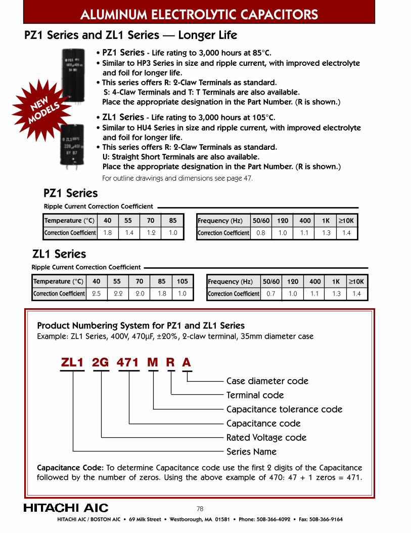
78
ALUMINUM ELECTROLYTIC CAPACITORS
HITACHI AIC / BOSTON AIC • 69 Milk Street • Westborough, MA 01581 • Phone: 508-366-4092 • Fax: 508-366-9164
AIC
• PZ1 Series - Life rating to 3,000 hours at 85°C.• Similar to HP3 Series in size and ripple current, with improved electrolyte and foil for longer life.• This series offers R: 2-Claw Terminals as standard. S: 4-Claw Terminals and T: T Terminals are also available. Place the appropriate designation in the Part Number. (R is shown.)
• ZL1 Series - Life rating to 3,000 hours at 105°C.• Similar to HU4 Series in size and ripple current, with improved electrolyte and foil for longer life.• This series offers R: 2-Claw Terminals as standard. U: Straight Short Terminals are also available. Place the appropriate designation in the Part Number. (R is shown.)
For outline drawings and dimensions see page 47.
Product Numbering System for PZ1 and ZL1 SeriesExample: ZL1 Series, 400V, 470µF, ±20%, 2-claw terminal, 35mm diameter case
Case diameter code
Terminal code
Capacitance tolerance code
Capacitance code
Rated Voltage code
Series Name
ZL1 2G 471 M R A
Capacitance Code: To determine Capacitance code use the first 2 digits of the Capacitancefollowed by the number of zeros. Using the above example of 470: 47 + 1 zeros = 471.
PZ1 Series and ZL1 Series — Longer Life
Frequency (Hz) 50/60 120 400 1K ≥10K
Correction Coefficient 0.7 1.0 1.1 1.3 1.4
Temperature (°C) 40 55 70 85 105
Correction Coefficient 2.5 2.2 2.0 1.8 1.0
Ripple Current Correction Coefficient
ZL1 Series
Frequency (Hz) 50/60 120 400 1K ≥10K
Correction Coefficient 0.8 1.0 1.1 1.3 1.4
Temperature (°C) 40 55 70 85
Correction Coefficient 1.8 1.4 1.2 1.0
Ripple Current Correction Coefficient
PZ1 Series
NEW
MODELS

79
detaRegatloV)CDVW(
traPrebmuN
ecnaticapaCeziSesaC
)mm(LxDØ
elppiRmumixaMtnerruC A( smr )
zH021,C°58@
mumixaMm(RSE Ω)
lacipyT)Hn(LSE
XRM122D21ZP 022 52X22 63.1 584 5XRM172D21ZP 072 52X22 05.1 593 6XRM133D21ZP 033 03X22 67.1 523 7YRM133D21ZP 033 52X52 98.1 523 7XRM193D21ZP 093 03X22 29.1 572 7YRM193D21ZP 093 52X52 09.1 572 7XRM174D21ZP 074 53X22 32.2 032 9ZRM174D21ZP 074 52X03 32.2 032 9XRM165D21ZP 065 04X22 45.2 091 9ZRM165D21ZP 065 52X03 44.2 091 9XRM186D21ZP 086 54X22 29.2 061 11ARM186D21ZP 086 52X53 68.2 061 11YRM128D21ZP 028 04X52 62.3 031 11ARM128D21ZP 028 52X53 31.3 031 11YRM201D21ZP 000,1 05X52 29.3 011 31ARM201D21ZP 000,1 03X53 66.3 011 31ZRM221D21ZP 002,1 04X03 91.4 09 41ARM221D21ZP 002,1 63X53 52.4 09 41ARM251D21ZP 005,1 04X53 39.4 57 41ASM281D21ZP 008,1 05X53 48.5 06 51XRM122E21ZP 022 52X22 63.1 584 5XRM172E21ZP 072 03X22 06.1 593 6YRM172E21ZP 072 52X52 85.1 593 6XRM133E21ZP 033 53X22 78.1 523 7YRM133E21ZP 033 03X52 68.1 523 7XRM193E21ZP 093 53X22 40.2 572 8ZRM193E21ZP 093 52X03 40.2 572 8XRM174E21ZP 074 04X22 53.2 032 8ARM174E21ZP 074 52X53 83.2 032 8XRM165E21ZP 065 05X22 18.2 091 9ARM165E21ZP 065 52X53 95.2 091 9YRM186E21ZP 086 54X52 11.3 061 9ARM186E21ZP 086 03X53 10.3 061 9YRM128E21ZP 028 05X52 55.3 031 01ARM128E21ZP 028 03X53 13.3 031 01ZRM201E21ZP 000,1 54X03 00.4 011 11ARM201E21ZP 000,1 63X53 88.3 011 11ZRM221E21ZP 002,1 05X03 55.4 09 11ARM221E21ZP 002,1 04X53 04.4 09 11ASM251E21ZP 005,1 05X53 43.5 57 21
HITACHI AIC / BOSTON AIC • 69 Milk Street • Westborough, MA 01581 • Phone: 508-366-4092 • Fax: 508-366-9164
AIC
ALUMINUM ELECTROLYTIC CAPACITORSPZ1 Series •Life rating to 3,000 hours at 85°C
•Temperature range –40°C to +85°C
200 Volts(Code: 2D)
250 Volts(Code: 2E)
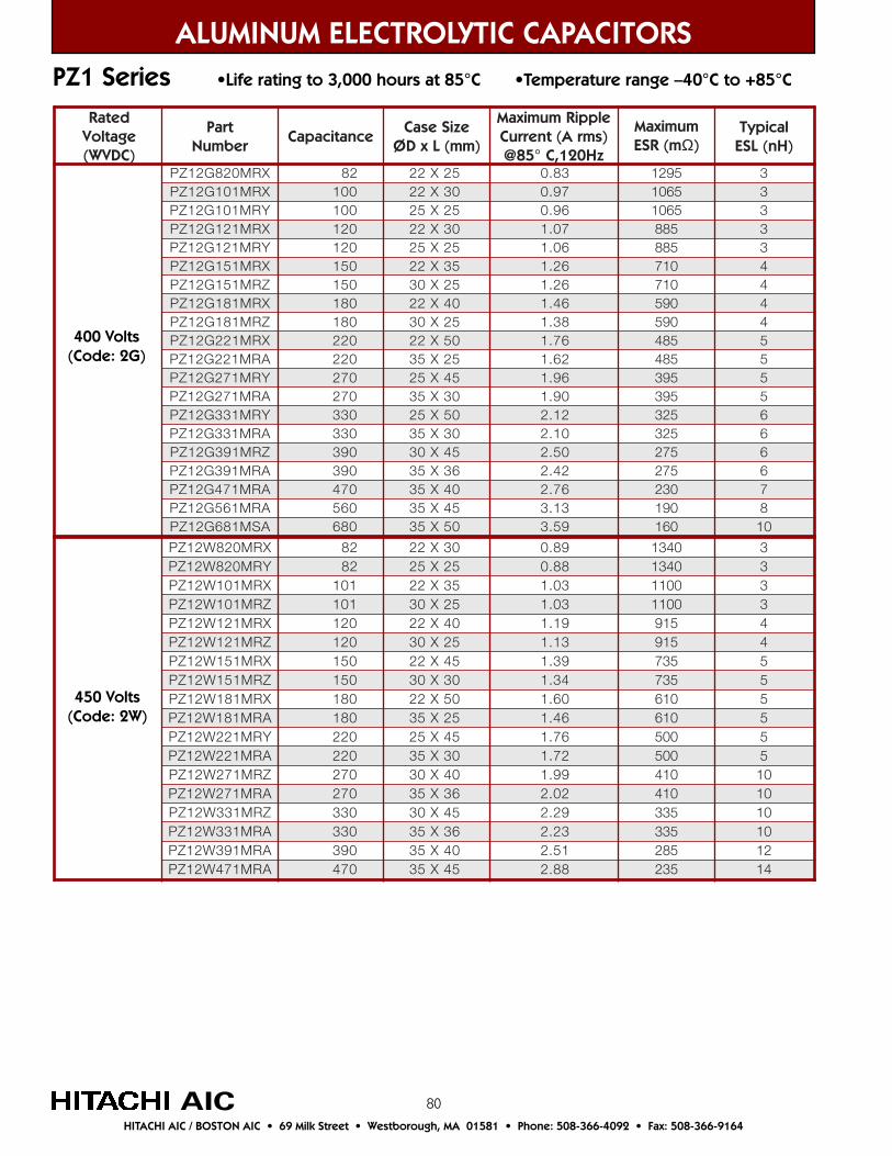
80
ALUMINUM ELECTROLYTIC CAPACITORS
HITACHI AIC / BOSTON AIC • 69 Milk Street • Westborough, MA 01581 • Phone: 508-366-4092 • Fax: 508-366-9164
AIC
detaRegatloV)CDVW(
traPrebmuN
ecnaticapaCeziSesaC
)mm(LxDØ
elppiRmumixaMtnerruC A( smr )
zH021,C°58@
mumixaMm(RSE Ω)
lacipyT)Hn(LSE
XRM028G21ZP 28 52X22 38.0 5921 3XRM101G21ZP 001 03X22 79.0 5601 3YRM101G21ZP 001 52X52 69.0 5601 3XRM121G21ZP 021 03X22 70.1 588 3YRM121G21ZP 021 52X52 60.1 588 3XRM151G21ZP 051 53X22 62.1 017 4ZRM151G21ZP 051 52X03 62.1 017 4XRM181G21ZP 081 04X22 64.1 095 4ZRM181G21ZP 081 52X03 83.1 095 4XRM122G21ZP 022 05X22 67.1 584 5ARM122G21ZP 022 52X53 26.1 584 5YRM172G21ZP 072 54X52 69.1 593 5ARM172G21ZP 072 03X53 09.1 593 5YRM133G21ZP 033 05X52 21.2 523 6ARM133G21ZP 033 03X53 01.2 523 6ZRM193G21ZP 093 54X03 05.2 572 6ARM193G21ZP 093 63X53 24.2 572 6ARM174G21ZP 074 04X53 67.2 032 7ARM165G21ZP 065 54X53 31.3 091 8ASM186G21ZP 086 05X53 95.3 061 01
XRM028W21ZP 28 03X22 98.0 0431 3YRM028W21ZP 28 52X52 88.0 0431 3XRM101W21ZP 101 53X22 30.1 0011 3ZRM101W21ZP 101 52X03 30.1 0011 3XRM121W21ZP 021 04X22 91.1 519 4ZRM121W21ZP 021 52X03 31.1 519 4XRM151W21ZP 051 54X22 93.1 537 5ZRM151W21ZP 051 03X03 43.1 537 5XRM181W21ZP 081 05X22 06.1 016 5ARM181W21ZP 081 52X53 64.1 016 5YRM122W21ZP 022 54X52 67.1 005 5ARM122W21ZP 022 03X53 27.1 005 5ZRM172W21ZP 072 04X03 99.1 014 01ARM172W21ZP 072 63X53 20.2 014 01ZRM133W21ZP 033 54X03 92.2 533 01ARM133W21ZP 033 63X53 32.2 533 01ARM193W21ZP 093 04X53 15.2 582 21ARM174W21ZP 074 54X53 88.2 532 41
400 Volts(Code: 2G)
450 Volts(Code: 2W)
PZ1 Series •Life rating to 3,000 hours at 85°C •Temperature range –40°C to +85°C
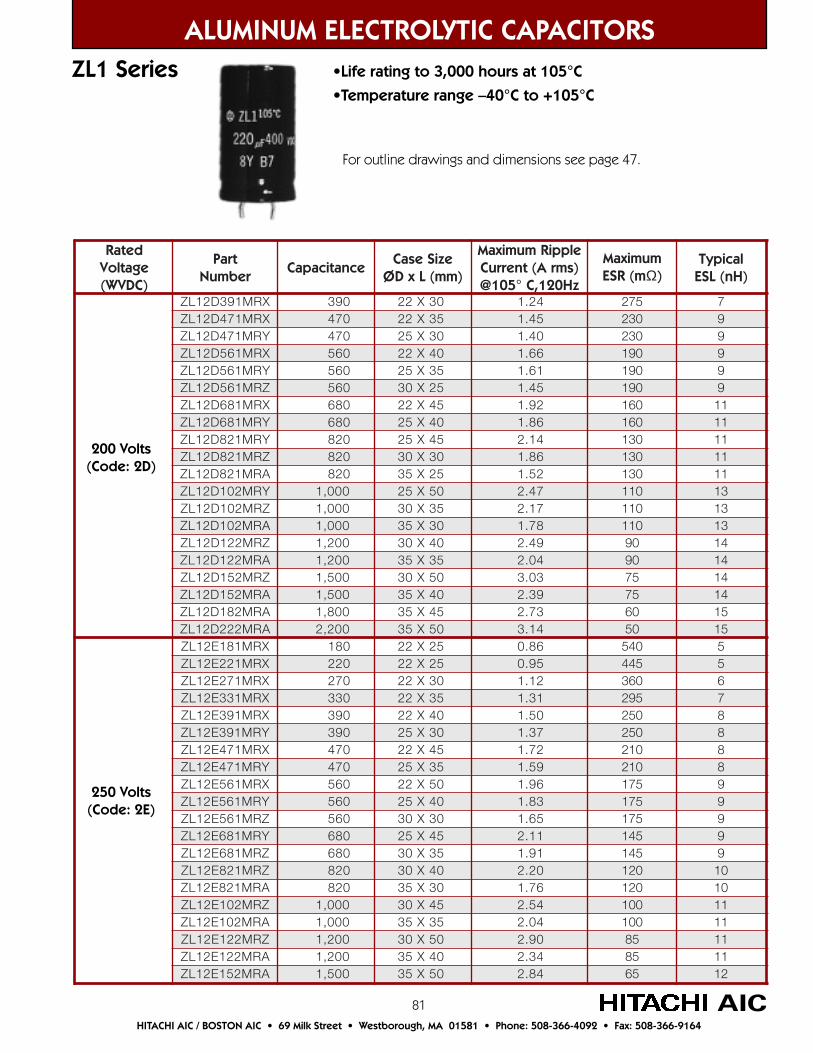
81
detaRegatloV)CDVW(
traPrebmuN
ecnaticapaCeziSesaC
)mm(LxDØ
elppiRmumixaMtnerruC )smrA(
zH021,C°501@
mumixaMm(RSE Ω)
lacipyT)Hn(LSE
XRM193D21LZ 093 03X22 42.1 572 7XRM174D21LZ 074 53X22 54.1 032 9YRM174D21LZ 074 03X52 04.1 032 9XRM165D21LZ 065 04X22 66.1 091 9YRM165D21LZ 065 53X52 16.1 091 9ZRM165D21LZ 065 52X03 54.1 091 9XRM186D21LZ 086 54X22 29.1 061 11YRM186D21LZ 086 04X52 68.1 061 11YRM128D21LZ 028 54X52 41.2 031 11ZRM128D21LZ 028 03X03 68.1 031 11ARM128D21LZ 028 52X53 25.1 031 11YRM201D21LZ 000,1 05X52 74.2 011 31ZRM201D21LZ 000,1 53X03 71.2 011 31ARM201D21LZ 000,1 03X53 87.1 011 31ZRM221D21LZ 002,1 04X03 94.2 09 41ARM221D21LZ 002,1 53X53 40.2 09 41ZRM251D21LZ 005,1 05X03 30.3 57 41ARM251D21LZ 005,1 04X53 93.2 57 41ARM281D21LZ 008,1 54X53 37.2 06 51ARM222D21LZ 002,2 05X53 41.3 05 51XRM181E21LZ 081 52X22 68.0 045 5XRM122E21LZ 022 52X22 59.0 544 5XRM172E21LZ 072 03X22 21.1 063 6XRM133E21LZ 033 53X22 13.1 592 7XRM193E21LZ 093 04X22 05.1 052 8YRM193E21LZ 093 03X52 73.1 052 8XRM174E21LZ 074 54X22 27.1 012 8YRM174E21LZ 074 53X52 95.1 012 8XRM165E21LZ 065 05X22 69.1 571 9YRM165E21LZ 065 04X52 38.1 571 9ZRM165E21LZ 065 03X03 56.1 571 9YRM186E21LZ 086 54X52 11.2 541 9ZRM186E21LZ 086 53X03 19.1 541 9ZRM128E21LZ 028 04X03 02.2 021 01ARM128E21LZ 028 03X53 67.1 021 01ZRM201E21LZ 000,1 54X03 45.2 001 11ARM201E21LZ 000,1 53X53 40.2 001 11ZRM221E21LZ 002,1 05X03 09.2 58 11ARM221E21LZ 002,1 04X53 43.2 58 11ARM251E21LZ 005,1 05X53 48.2 56 21
ALUMINUM ELECTROLYTIC CAPACITORS
HITACHI AIC / BOSTON AIC • 69 Milk Street • Westborough, MA 01581 • Phone: 508-366-4092 • Fax: 508-366-9164
AIC
ZL1 Series •Life rating to 3,000 hours at 105°C•Temperature range –40°C to +105°C
200 Volts(Code: 2D)
250 Volts(Code: 2E)
For outline drawings and dimensions see page 47.
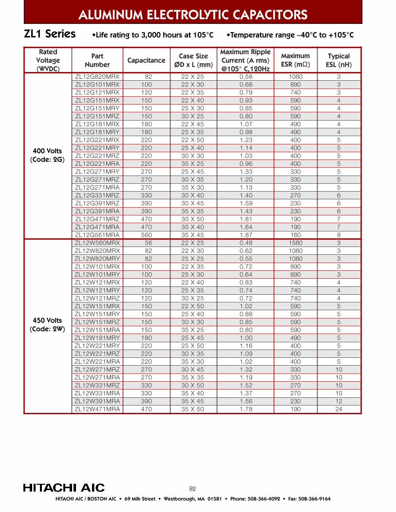
82
detaRegatloV)CDVW(
traPrebmuN
ecnaticapaCeziSesaC
)mm(LxDØ
elppiRmumixaM)smrA(tnerruCzH021,C°501@
mumixaMm(RSE Ω)
lacipyT)Hn(LSE
XRM028G21LZ 28 52X22 85.0 0801 3XRM101G21LZ 001 03X22 86.0 098 3XRM121G21LZ 021 53X22 97.0 047 3XRM151G21LZ 051 04X22 39.0 095 4YRM151G21LZ 051 03X52 58.0 095 4ZRM151G21LZ 051 52X03 08.0 095 4XRM181G21LZ 081 54X22 70.1 094 4YRM181G21LZ 081 53X52 89.0 094 4XRM122G21LZ 022 05X22 32.1 004 5YRM122G21LZ 022 04X52 41.1 004 5ZRM122G21LZ 022 03X03 30.1 004 5ARM122G21LZ 022 52X53 69.0 004 5YRM172G21LZ 072 54X52 33.1 033 5ZRM172G21LZ 072 53X03 02.1 033 5ARM172G21LZ 072 03X53 31.1 033 5ZRM133G21LZ 033 04X03 04.1 072 6ZRM193G21LZ 093 54X03 95.1 032 6ARM193G21LZ 093 53X53 34.1 032 6ZRM174G21LZ 074 05X03 18.1 091 7ARM174G21LZ 074 04X53 46.1 091 7ARM165G21LZ 065 54X53 78.1 061 8XRM065W21LZ 65 52X22 84.0 0851 3XRM028W21LZ 28 03X22 26.0 0801 3YRM028W21LZ 28 52X52 55.0 0801 3XRM101W21LZ 001 53X22 27.0 098 3YRM101W21LZ 001 03X52 46.0 098 3XRM121W21LZ 021 04X22 38.0 047 4YRM121W21LZ 021 53X52 47.0 047 4ZRM121W21LZ 021 52X03 27.0 047 4XRM151W21LZ 051 05X22 20.1 095 5YRM151W21LZ 051 04X52 88.0 095 5ZRM151W21LZ 051 03X03 58.0 095 5ARM151W21LZ 051 52X53 08.0 095 5YRM181W21LZ 081 54X52 00.1 094 5YRM122W21LZ 022 05X52 61.1 004 5ZRM122W21LZ 022 53X03 90.1 004 5ARM122W21LZ 022 03X53 20.1 004 5ZRM172W21LZ 072 54X03 23.1 033 01ARM172W21LZ 072 53X53 91.1 033 01ZRM133W21LZ 033 05X03 25.1 072 01ARM133W21LZ 033 04X53 73.1 072 01ARM193W21LZ 093 54X53 65.1 032 21ARM174W21LZ 074 05X53 87.1 091 42
ALUMINUM ELECTROLYTIC CAPACITORS
HITACHI AIC / BOSTON AIC • 69 Milk Street • Westborough, MA 01581 • Phone: 508-366-4092 • Fax: 508-366-9164
AIC
ZL1 Series •Life rating to 3,000 hours at 105°C •Temperature range –40°C to +105°C
400 Volts(Code: 2G)
450 Volts(Code: 2W)

83
ALUMINUM ELECTROLYTIC CAPACITORS
HITACHI AIC / BOSTON AIC • 69 Milk Street • Westborough, MA 01581 • Phone: 508-366-4092 • Fax: 508-366-9164
AIC
XL1 Series •Life rating to 10,000 hours at 105°C •Temperature range –40°C to +105°C
Product Numbering System for XL1 SeriesExample: XL1 Series, 450V, 100µF, ±20%, 2-claw terminal, 22mm diameter case
Case diameter code
Terminal code
Capacitance tolerance code
Capacitance code
Rated Voltage code
Series Name
XL1 2W 101 M R X
Capacitance Code: To determine Capacitance code use the first 2 digits of the Capacitancefollowed by the number of zeros. Using the above example of 101: 10 + 1 zero = 101.
Frequency (Hz) 50/60 120 400 1K ≥10K
Correction Coefficient 0.7 1.0 1.1 1.3 1.4
Temperature (°C) 40 55 70 85 105
Correction Coefficient 2.5 2.2 2.0 1.8 1.0
Ripple Current Correction Coefficient
XL1 Series
• XL1 Series - Life rating to 10,000 hours at 105°C.• Similar to the superceded HL1 Series in size and ripple current, with improved electrolyte and foil for longer life.• This series offers R: 2-Claw Terminals as standard. S: 4-Claw Terminals and T: T terminals are also available. Place the appropriate designation in the Part Number. (R is shown.)
For outline drawings and dimensions see page 47.
NEW
MODEL
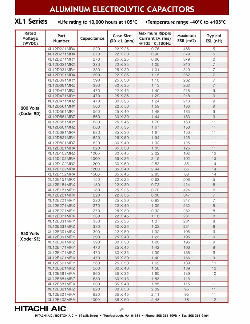
84
ALUMINUM ELECTROLYTIC CAPACITORS
HITACHI AIC / BOSTON AIC • 69 Milk Street • Westborough, MA 01581 • Phone: 508-366-4092 • Fax: 508-366-9164
AIC
XL1 Series •Life rating to 10,000 hours at 105°C •Temperature range –40°C to +105°C
detaRegatloV)CDVW(
traPrebmuN
ecnaticapaCeziSesaC
)mm(LxDØ
elppiRmumixaMtnerruC A( smr )
zH021,C°501@
mumixaMm(RSE Ω)
lacipyT)Hn(LSE
XRM122D21LX 022 52X22 67.0 564 5XRM172D21LX 072 03X22 09.0 973 6YRM172D21LX 072 52X52 68.0 973 6XRM133D21LX 033 53X22 50.1 013 7YRM133D21LX 033 03X52 10.1 013 7XRM193D21LX 093 53X22 51.1 262 7YRM193D21LX 093 03X52 01.1 262 7ZRM193D21LX 093 52X03 31.1 262 7XRM174D21LX 074 54X22 04.1 812 9YRM174D21LX 074 53X52 92.1 812 9ZRM174D21LX 074 52X03 42.1 812 9XRM165D21LX 065 05X22 95.1 381 9YRM165D21LX 065 04X52 84.1 381 9ZRM165D21LX 065 03X03 44.1 381 9YRM186D21LX 086 54X52 07.1 051 11ZRM186D21LX 086 53X03 76.1 051 11ARM186D21LX 086 03X53 76.1 051 11YRM128D21LX 028 05X52 49.1 521 11ZRM128D21LX 028 04X03 29.1 521 11ARM128D21LX 028 03X53 38.1 521 11ZRM201D21LX 0001 54X03 22.2 201 31ARM201D21LX 0001 53X53 51.2 201 31ZRM221D21LX 0021 05X03 35.2 58 41ARM221D21LX 0021 04X53 44.2 58 41ARM251D21LX 0051 54X53 58.2 86 41XRM151E21LX 051 52X22 26.0 805 5XRM181E21LX 081 03X22 37.0 424 6YRM181E21LX 081 52X52 07.0 424 6XRM122E21LX 022 53X22 68.0 743 7YRM122E21LX 022 03X52 38.0 743 7XRM172E21LX 072 04X22 00.1 282 8YRM172E21LX 072 03X52 29.0 282 8XRM133E21LX 033 54X22 61.1 132 8YRM133E21LX 033 53X52 70.1 132 8ZRM133E21LX 033 52X03 30.1 132 8XRM193E21LX 093 05X22 23.1 591 9YRM193E21LX 093 04X52 32.1 591 9ZRM193E21LX 093 03X03 02.1 591 9YRM174E21LX 074 54X52 24.1 661 9ZRM174E21LX 074 53X03 93.1 661 9ARM174E21LX 074 03X53 04.1 661 9YRM165E21LX 065 05X52 26.1 931 01ZRM165E21LX 065 04X03 85.1 931 01ARM165E21LX 065 53X53 06.1 931 01ZRM186E21LX 086 54X03 38.1 511 11ARM186E21LX 086 04X53 58.1 511 11ZRM128E21LX 028 05X03 90.2 59 11ARM128E21LX 028 54X53 11.2 59 11ARM201E21LX 0001 05X53 34.2 87 21
200 Volts(Code: 2D)
250 Volts(Code: 2E)
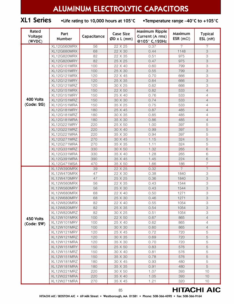
85
ALUMINUM ELECTROLYTIC CAPACITORS
HITACHI AIC / BOSTON AIC • 69 Milk Street • Westborough, MA 01581 • Phone: 508-366-4092 • Fax: 508-366-9164
AIC
XL1 Series •Life rating to 10,000 hours at 105°C •Temperature range –40°C to +105°C
detaRegatloV)CDVW(
traPrebmuN
ecnaticapaCeziSesaC
)mm(LxDØ
elppiRmumixaMtnerruC A( smr )
zH021,C°501@
mumixaMm(RSE Ω)
lacipyT)Hn(LSE
XRM065G21LX 65 52X22 73.0 ? ?XRM086G21LX 86 03X22 44.0 8411 3XRM028G21LX 28 53X22 15.0 579 3YRM028G21LX 28 52X52 74.0 579 3XRM101G21LX 001 04X22 06.0 997 3YRM101G21LX 001 03X52 55.0 997 3XRM121G21LX 021 54X22 07.0 666 3YRM121G21LX 021 53X52 46.0 666 3ZRM121G21LX 021 52X03 26.0 666 3XRM151G21LX 051 05X22 28.0 335 4YRM151G21LX 051 04X52 67.0 335 4ZRM151G21LX 051 03X03 47.0 335 4ARM151G21LX 051 52X53 57.0 335 4YRM181G21LX 081 54X52 78.0 584 4ZRM181G21LX 081 53X03 58.0 584 4ARM181G21LX 081 03X53 68.0 584 4YRM122G21LX 022 05X52 00.1 793 5ZRM122G21LX 022 04X03 99.0 793 5ARM122G21LX 022 03X53 49.0 793 5ZRM172G21LX 072 54X03 51.1 423 5ARM172G21LX 072 53X53 11.1 423 5ZRM133G21LX 033 05X03 23.1 562 6ARM133G21LX 033 04X53 82.1 562 6ARM193G21LX 093 54X53 54.1 422 6ASM174G21LX 074 05X53 66.1 681 7XRM093W21LX 93 52X22 23.0 ? ?XRM074W21LX 74 03X22 83.0 0481 3YRM074W21LX 74 52X52 63.0 0481 3XRM065W21LX 65 53X22 34.0 4451 3YRM065W21LX 65 03X52 34.0 4451 3XRM086W21LX 86 04X22 05.0 1721 3YRM086W21LX 86 03X52 64.0 1721 3XRM028W21LX 28 04X22 55.0 4501 3YRM028W21LX 28 53X52 45.0 4501 3ZRM028W21LX 28 52X03 15.0 4501 3XRM101W21LX 001 05X22 76.0 568 4YRM101W21LX 001 04X52 26.0 568 4ZRM101W21LX 001 03X03 06.0 568 4YRM121W21LX 021 54X52 27.0 027 5ZRM121W21LX 021 53X03 96.0 027 5ARM121W21LX 021 03X53 07.0 027 5YRM151W21LX 051 05X52 38.0 675 5ZRM151W21LX 051 04X03 18.0 675 5ARM151W21LX 051 03X53 87.0 675 5ZRM181W21LX 081 54X03 39.0 084 5ARM181W21LX 081 53X53 19.0 084 5ZRM122W21LX 022 05X03 70.1 393 01ARM122W21LX 022 04X53 50.1 393 01ARM172W21LX 072 54X53 12.1 023 01
400 Volts(Code: 2G)
450 Volts(Code: 2W)
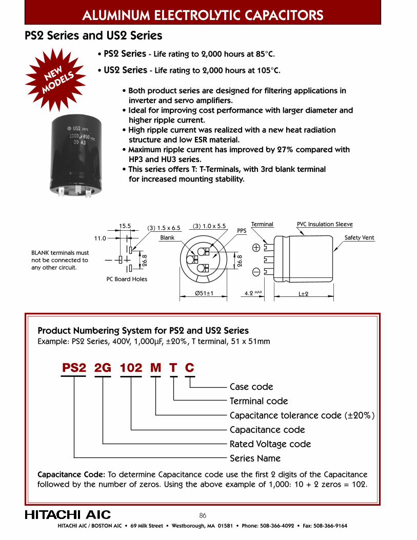
86
ALUMINUM ELECTROLYTIC CAPACITORS
HITACHI AIC / BOSTON AIC • 69 Milk Street • Westborough, MA 01581 • Phone: 508-366-4092 • Fax: 508-366-9164
AIC
Product Numbering System for PS2 and US2 SeriesExample: PS2 Series, 400V, 1,000µF, ±20%, T terminal, 51 x 51mm
Case code
Terminal code
Capacitance tolerance code (±20%)
Capacitance code
Rated Voltage code
Series Name
PS2 2G 102 M T C
Capacitance Code: To determine Capacitance code use the first 2 digits of the Capacitancefollowed by the number of zeros. Using the above example of 1,000: 10 + 2 zeros = 102.
• PS2 Series - Life rating to 2,000 hours at 85°C.
• US2 Series - Life rating to 2,000 hours at 105°C.
• Both product series are designed for filtering applications in inverter and servo amplifiers.• Ideal for improving cost performance with larger diameter and higher ripple current.• High ripple current was realized with a new heat radiation structure and low ESR material.• Maximum ripple current has improved by 27% compared with HP3 and HU3 series.• This series offers T: T-Terminals, with 3rd blank terminal for increased mounting stability.
PS2 Series and US2 Series
11.0
15.5 (3) 1.5 x 6.5 (3) 1.0 x 5.5
BlankPPS
Ø51±1
Terminal PVC Insulation Sleeve
4.2 MAX L±2
Safety Vent
26.8
26.8
PC Board Holes
BLANK terminals mustnot be connected toany other circuit.
NEW
MODELS
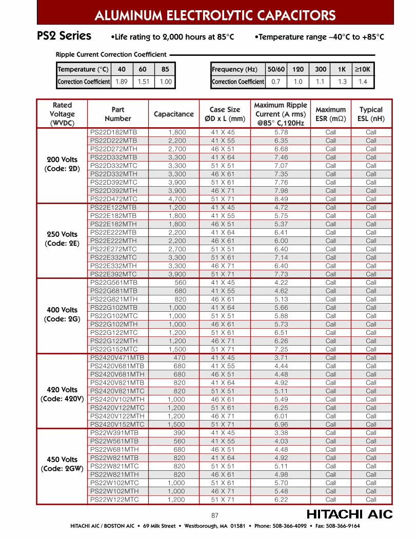
87
detaRegatloV)CDVW(
traPrebmuN
ecnaticapaCeziSesaC
)mm(LxDØ
elppiRmumixaMtnerruC A( smr )
@ 58 zH021,C°
mumixaMm(RSE Ω)
lacipyT)Hn(LSE
BTM281D22SP 8,1 00 54X14 87.5 llaC llaCBTM222D22SP 2,2 00 55X14 53.6 llaC llaCHTM272D22SP 7,2 00 15X64 86.6 llaC llaCBTM233D22SP 3,3 00 46X14 64.7 llaC llaCCTM233D22SP 3,3 00 15X15 70.7 llaC llaCHTM233D22SP 3,3 00 16X64 53.7 llaC llaCCTM293D22SP 9,3 00 15 X 16 67.7 llaC llaCHTM293D22SP 9,3 00 17X64 89.7 llaC llaCCTM274D22SP 7,4 00 15 X 17 94.8 llaC llaCBTM221E22SP 2,1 00 41 54X 27.4 llaC llaCBTM281E22SP 8,1 00 41 X 55 57.5 llaC llaCHTM281E22SP 8,1 00 64 X 15 73.5 llaC llaCBTM222E22SP 2,2 00 41 46X 14.6 llaC llaCHTM222E22SP 2,2 00 64 6X 1 00.6 llaC llaCCTM272E22SP 7,2 00 15 X 15 04.6 llaC llaCCTM233E22SP 3,3 00 X15 16 41.7 llaC llaCHTM233E22SP 3,3 00 64 7X 1 04.6 llaC llaCCTM293E22SP 9,3 00 15 X 17 37.7 llaC llaCBTM165G22SP 65 0 14 54X 22.4 llaC llaCBTM186G22SP 086 14 X 55 26.4 llaC llaCHTM128G22SP 28 0 64 6X 1 31.5 llaC llaCBTM201G22SP 1 000, 14 46X 66.5 llaC llaCCTM201G22SP 1 000, 15 X 15 88.5 llaC llaCHTM201G22SP 1 000, 64 6X 1 37.5 llaC llaCCTM221G22SP 2,1 00 15 X 16 15.6 llaC llaCHTM221G22SP 1,2 00 64 7X 1 62.6 llaC llaCCTM251G22SP 5,1 00 15 X 17 52.7 llaC llaC
BTM174V0242SP 74 0 14 X 54 17.3 llaC llaCBTM186V0242SP 86 0 14 X 55 44.4 llaC llaCHTM186V0242SP 86 0 64 X 15 84.4 llaC llaCBTM128V0242SP 28 0 14 X 46 29.4 llaC llaCCTM128V0242SP 28 0 15 X 15 11.5 llaC llaCHTM201V0242SP ,1 0 00 64 X 16 94.5 llaC llaCCTM221V0242SP 002,1 15 X 16 52.6 llaC llaCHTM221V0242SP 002,1 64 7X 1 10.6 llaC llaCCTM251V0242SP 005,1 15 X 17 69.6 llaC llaC
BTM193W22SP 93 0 14 54X 83.3 llaC llaCBTM165W22SP 65 0 14 X 55 30.4 llaC llaCHTM186W22SP 86 0 64 X 15 84.4 llaC llaCBTM128W22SP 028 14 46X 29.4 llaC llaCCTM128W22SP 028 15 X 15 11.5 llaC llaCHTM128W22SP 028 64 6X 1 89.4 llaC llaCCTM201W22SP 000,1 16X15 07.5 llaC llaCHTM201W22SP 000,1 17X64 84.5 llaC llaCCTM221W22SP 002,1 15 X 17 22.6 llaC llaC
ALUMINUM ELECTROLYTIC CAPACITORS
HITACHI AIC / BOSTON AIC • 69 Milk Street • Westborough, MA 01581 • Phone: 508-366-4092 • Fax: 508-366-9164
AIC
200 Volts(Code: 2D)
250 Volts(Code: 2E)
400 Volts(Code: 2G)
420 Volts(Code: 420V)
450 Volts(Code: 2GW)
PS2 Series •Life rating to 2,000 hours at 85°C •Temperature range –40°C to +85°C
Temperature (°C) 40 60 85
Correction Coefficient 1.89 1.51 1.00
Frequency (Hz) 50/60 120 300 1K ≥10K
Correction Coefficient 0.7 1.0 1.1 1.3 1.4
Ripple Current Correction Coefficient
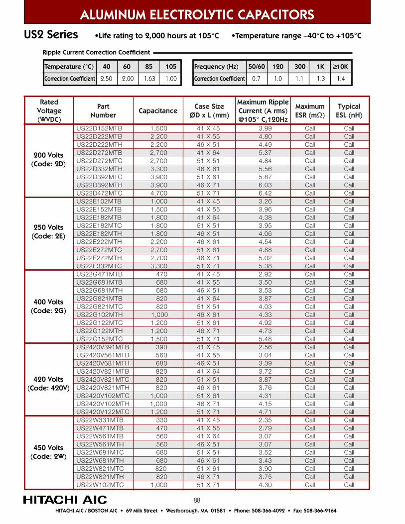
88
detaRegatloV)CDVW(
traPrebmuN
ecnaticapaCeziSesaC
)mm(LxDØ
elppiRmumixaMtnerruC A( smr )
01@ 5 zH021,C°
mumixaMm(RSE Ω)
lacipyT)Hn(LSE
BTM251D22SU 5,1 00 . 54X14 99.3 llaC llaCBTM222D22SU 2,2 00 . 14 X 55 08.4 llaC llaCHTM222D22SU 2,2 00 . 64 X 15 94.4 llaC llaCBTM272D22SU 7,2 00 . 46X14 73.5 llaC llaCCTM272D22SU 7,2 00 . 15X15 48.4 llaC llaCHTM233D22SU 3,3 00 . 64 X 16 65.5 llaC llaCCTM293D22SU 9,3 00 . 15 X 16 78.5 llaC llaCHTM293D22SU 9,3 00 . 64 X 17 30.6 llaC llaCCTM274D22SU 7,4 00 . 15 X 17 24.6 llaC llaCBTM201E22SU 0,1 00 . 41 54X 62.3 llaC llaCBTM251E22SU 5,1 00 . 41 X 55 69.3 llaC llaCBTM281E22SU 8,1 00 . 41 46X 83.4 llaC llaCCTM281E22SU 8,1 00 . 15 X 15 59.3 llaC llaCHTM281E22SU 8,1 00 . 64 X 15 60.4 llaC llaCHTM222E22SU 2,2 00 . 64 6X 1 45.4 llaC llaCCTM272E22SU 7,2 00 . X15 16 88.4 llaC llaCHTM272E22SU 7,2 00 . 64 7X 1 20.5 llaC llaCCTM233E22SU 3,3 00 . 15 X 17 83.5 llaC llaCBTM174G22SU 074 . 14 54X 29.2 llaC llaCBTM186G22SU 86 0. 14 X 55 05.3 llaC llaCHTM186G22SU 86 0. 64 X 15 35.3 llaC llaCBTM128G22SU 28 0. 14 46X 78.3 llaC llaCCTM128G22SU 28 0. 15 X 15 30.4 llaC llaCHTM201G22SU 000,1 64 6X 1 33.4 llaC llaCCTM221G22SU 2,1 00 . 15 X 16 29.4 llaC llaCHTM221G22SU 002,1 . 64 7X 1 37.4 llaC llaCCTM251G22SU 5,1 00 . 15 X 17 84.5 llaC llaC
BTM193V0242SU 93 0. 14 X 54 65.2 llaC llaCBTM165V0242SU 65 0. 14 X 55 40.3 llaC llaCHTM186V0242SU 86 0. 64 X 15 93.3 llaC llaCBTM128V0242SU 28 0. 14 X 46 27.3 llaC llaCCTM128V0242SU 28 0. 15 X 15 78.3 llaC llaCHTM128V0242SU 28 0. 64 X 16 67.3 llaC llaCCTM201V0242SU 000,1 . 15 X 16 13.4 llaC llaCHTM201V0242SU 00,1 0. 64 X 17 51.4 llaC llaCCTM221V0242SU 002,1 . 15 X 17 17.4 llaC llaC
BTM133W22SU 33 0. 14 54X 53.2 llaC llaCBTM174W22SU 74 0. 14 X 55 97.2 llaC llaCBTM165W22SU 65 0. 14 46X 70.3 llaC llaCHTM165W22SU 65 0. 64 X 15 70.3 llaC llaCCTM186W22SU 86 0. 15 X 15 25.3 llaC llaCHTM186W22SU 86 0. 64 6X 1 34.3 llaC llaCCTM128W22SU 028 . 16X15 09.3 llaC llaCHTM128W22SU 28 0. 64 7X 1 57.3 llaC llaCCTM201W22SU ,1 0 00 . 15 X 17 03.4 llaC llaC
US2 Series •Life rating to 2,000 hours at 105°C •Temperature range –40°C to +105°C
200 Volts(Code: 2D)
250 Volts(Code: 2E)
400 Volts(Code: 2G)
420 Volts(Code: 420V)
450 Volts(Code: 2W)
Temperature (°C) 40 60 85 105
Correction Coefficient 2.50 2.00 1.63 1.00
Frequency (Hz) 50/60 120 300 1K ≥10K
Correction Coefficient 0.7 1.0 1.1 1.3 1.4
Ripple Current Correction Coefficient
ALUMINUM ELECTROLYTIC CAPACITORS
HITACHI AIC / BOSTON AIC • 69 Milk Street • Westborough, MA 01581 • Phone: 508-366-4092 • Fax: 508-366-9164
AIC
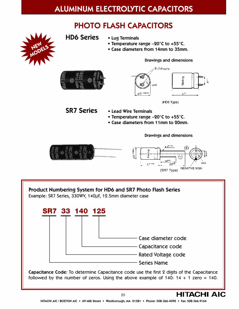
89
ALUMINUM ELECTROLYTIC CAPACITORS
HITACHI AIC / BOSTON AIC • 69 Milk Street • Westborough, MA 01581 • Phone: 508-366-4092 • Fax: 508-366-9164
AIC
NEW
MODELS
PHOTO FLASH CAPACITORS
Product Numbering System for HD6 and SR7 Photo Flash SeriesExample: SR7 Series, 330WV, 140µF, 12.5mm diameter case
Case diameter code
Capacitance code
Rated Voltage code
Series Name
SR7 33 140 125
Capacitance Code: To determine Capacitance code use the first 2 digits of the Capacitancefollowed by the number of zeros. Using the above example of 140: 14 + 1 zero = 140.
HD6 Series • Lug Terminals• Temperature range –20°C to +55°C.• Case diameters from 14mm to 35mm.
SR7 Series • Lead Wire Terminals• Temperature range –20°C to +55°C.• Case diameters from 11mm to 20mm.
Drawings and dimensions
Drawings and dimensions
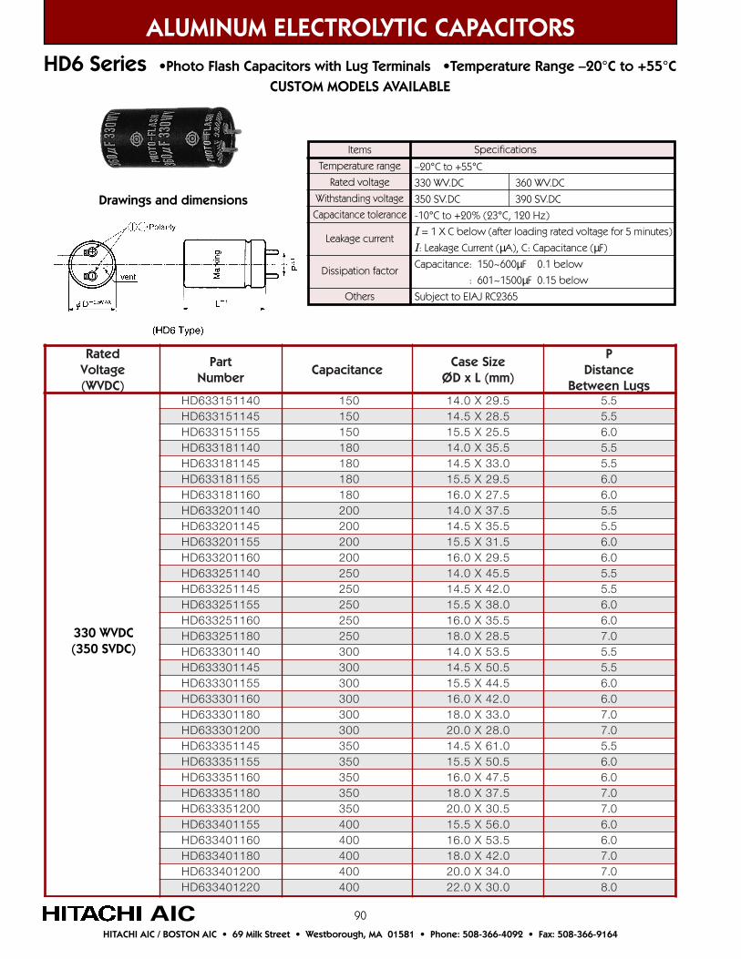
90
HD6 Series •Photo Flash Capacitors with Lug Terminals •Temperature Range –20°C to +55°C CUSTOM MODELS AVAILABLE
ALUMINUM ELECTROLYTIC CAPACITORS
HITACHI AIC / BOSTON AIC • 69 Milk Street • Westborough, MA 01581 • Phone: 508-366-4092 • Fax: 508-366-9164
AIC
detaRegatloV)CDVW(
traPrebmuN
ecnaticapaCeziSesaC
)mm(LxDØ
PecnatsiD
sguLneewteB041151336DH 051 5.92X0.41 5.5541151336DH 051 5.82X5.41 5.5551151336DH 051 5.52X5.51 0.6041181336DH 081 5.53X0.41 5.5541181336DH 081 0.33X5.41 5.5551181336DH 081 5.92X5.51 0.6061181336DH 081 5.72X0.61 0.6041102336DH 002 5.73X0.41 5.5541102336DH 002 5.53X5.41 5.5551102336DH 002 5.13X5.51 0.6061102336DH 002 5.92X0.61 0.6041152336DH 052 5.54X0.41 5.5541152336DH 052 0.24X5.41 5.5551152336DH 052 0.83X5.51 0.6061152336DH 052 5.53X0.61 0.6081152336DH 052 5.82X0.81 0.7041103336DH 003 5.35X0.41 5.5541103336DH 003 5.05X5.41 5.5551103336DH 003 5.44X5.51 0.6061103336DH 003 0.24X0.61 0.6081103336DH 003 0.33X0.81 0.7002103336DH 003 0.82X0.02 0.7541153336DH 053 0.16X5.41 5.5551153336DH 053 5.05X5.51 0.6061153336DH 053 5.74X0.61 0.6081153336DH 053 5.73X0.81 0.7002153336DH 053 5.03X0.02 0.7551104336DH 004 0.65X5.51 0.6061104336DH 004 5.35X0.61 0.6081104336DH 004 0.24X0.81 0.7002104336DH 004 0.43X0.02 0.7022104336DH 004 0.03X0.22 0.8
330 WVDC(350 SVDC)
Items
Temperature range
Rated voltage
Withstanding voltage
Capacitance tolerance
Leakage current
Dissipation factor
Others
–20°C to +55°C
330 WV.DC 360 WV.DC
350 SV.DC 390 SV.DC
-10°C to +20% (23°C, 120 Hz)
I = 1 X C below (after loading rated voltage for 5 minutes)
I: Leakage Current (µA), C: Capacitance (µF)
Capacitance: 150~600µF 0.1 below
: 601~1500µF 0.15 below
Subject to EIAJ RC2365
Specifications
Drawings and dimensions
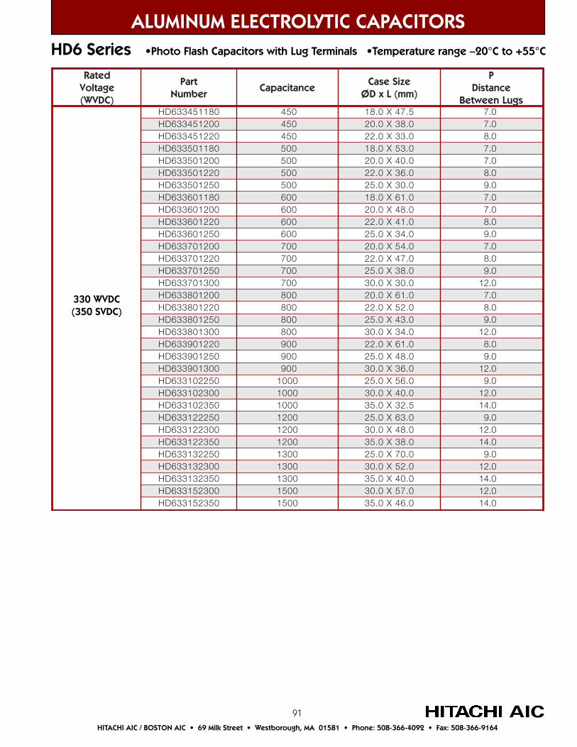
91
detaRegatloV)CDVW(
traPrebmuN
ecnaticapaCeziSesaC
)mm(LxDØ
PecnatsiD
sguLneewteB081154336DH 054 5.74X0.81 0.7002154336DH 054 0.83X0.02 0.7022154336DH 054 0.33X0.22 0.8081105336DH 005 0.35X0.81 0.7002105336DH 005 0.04X0.02 0.7022105336DH 005 0.63X0.22 0.8052105336DH 005 0.03X0.52 0.9081106336DH 006 0.16X0.81 0.7002106336DH 006 0.84X0.02 0.7022106336DH 006 0.14X0.22 0.8052106336DH 006 0.43X0.52 0.9002107336DH 007 0.45X0.02 0.7022107336DH 007 0.74X0.22 0.8052107336DH 007 0.83X0.52 0.9003107336DH 007 0.03X0.03 0.21002108336DH 008 0.16X0.02 0.7022108336DH 008 0.25X0.22 0.8052108336DH 008 0.34X0.52 0.9003108336DH 008 0.43X0.03 0.21022109336DH 009 0.16X0.22 0.8052109336DH 009 0.84X0.52 0.9003109336DH 009 0.63X0.03 0.21052201336DH 0001 0.65X0.52 0.9003201336DH 0001 0.04X0.03 0.21053201336DH 0001 5.23X0.53 0.41052221336DH 0021 0.36X0.52 0.9003221336DH 0021 0.84X0.03 0.21053221336DH 0021 0.83X0.53 0.41052231336DH 0031 0.07X0.52 0.9003231336DH 0031 0.25X0.03 0.21053231336DH 0031 0.04X0.53 0.41003251336DH 0051 0.75X0.03 0.21053251336DH 0051 0.64X0.53 0.41
ALUMINUM ELECTROLYTIC CAPACITORS
HITACHI AIC / BOSTON AIC • 69 Milk Street • Westborough, MA 01581 • Phone: 508-366-4092 • Fax: 508-366-9164
AIC
HD6 Series •Photo Flash Capacitors with Lug Terminals •Temperature range –20°C to +55°C
330 WVDC(350 SVDC)

92
HD6 Series •Photo Flash Capacitors with Lug Terminals •Temperature range –20°C to +55°C
ALUMINUM ELECTROLYTIC CAPACITORS
HITACHI AIC / BOSTON AIC • 69 Milk Street • Westborough, MA 01581 • Phone: 508-366-4092 • Fax: 508-366-9164
AIC
detaRegatloV)CDVW(
traPrebmuN
ecnaticapaCeziSesaC
)mm(LxDØ
PecnatsiD
sguLneewteB041151636DH 051 5.93X0.41 5.5541151636DH 051 5.73X5.41 5.5551151636DH 051 5.13X5.51 0.6061151636DH 051 5.92X0.61 0.6041181636DH 081 5.44X0.41 5.5541181636DH 081 0.24X5.41 5.5551181636DH 081 5.53X5.51 0.6061181636DH 081 0.33X0.61 0.6081181636DH 081 5.72X0.81 0.7041102636DH 002 5.74X0.41 5.5541102636DH 002 5.44X5.41 5.5551102636DH 002 5.93X5.51 0.6061102636DH 002 5.73X0.61 0.6081102636DH 002 5.13X0.81 0.7002102636DH 002 0.62X0.02 0.7041152636DH 052 0.65X0.41 5.5541152636DH 052 0.25X5.41 5.5551152636DH 052 5.74X5.51 0.6061152636DH 052 5.44X0.61 0.6081152636DH 052 5.73X0.81 0.7002152636DH 052 0.03X0.02 0.7022152636DH 052 0.72X0.22 0.8551103636DH 003 0.65X5.51 0.6061103636DH 003 0.25X0.61 0.6081103636DH 003 0.24X0.81 0.7002103636DH 003 0.43X0.02 0.7022103636DH 003 0.13X0.22 0.8052103636DH 003 0.72X0.52 0.9061153636DH 053 0.65X0.61 0.6081153636DH 053 5.74X0.81 0.7002153636DH 053 0.83X0.02 0.7022153636DH 053 0.53X0.22 0.8052153636DH 053 0.92X0.52 0.9081104636DH 004 0.25X0.81 0.7002104636DH 004 0.34X0.02 0.7022104636DH 004 0.73X0.22 0.8052104636DH 004 0.33X0.52 0.9081154636DH 054 0.16X0.81 0.7002154636DH 054 0.54X0.02 0.7022154636DH 054 0.14X0.22 0.8052154636DH 054 0.53X0.52 0.9
360 WVDC(390 SVDC)

93
ALUMINUM ELECTROLYTIC CAPACITORS
HITACHI AIC / BOSTON AIC • 69 Milk Street • Westborough, MA 01581 • Phone: 508-366-4092 • Fax: 508-366-9164
AIC
HD6 Series •Photo Flash Capacitors with Lug Terminals •Temperature range –20°C to +55°C
detaRegatloV)CDVW(
traPrebmuN
ecnaticapaCeziSesaC
)mm(LxDØ
PecnatsiD
sguLneewteB002105636DH 005 0.25X0.02 0.7022105636DH 005 0.64X0.22 0.8052105636DH 005 0.93X0.52 0.9003105636DH 005 0.13X0.03 0.21002106636DH 006 0.75X0.02 0.7022106636DH 006 0.25X0.22 0.8052106636DH 006 0.44X0.52 0.9003106636DH 006 0.33X0.03 0.21022107636DH 007 0.26X0.22 0.8052107636DH 007 0.35X0.52 0.9003107636DH 007 0.73X0.03 0.21052108636DH 008 0.26X0.52 0.9003108636DH 008 0.44X0.03 0.21053108636DH 008 0.53X0.53 0.41052109636DH 009 0.37X0.52 0.9003109636DH 009 0.94X0.03 0.21053109636DH 009 0.83X0.53 0.41003201636DH 0001 0.35X0.03 0.21053201636DH 0001 0.64X0.53 0.41003221636DH 0021 0.26X0.03 0.21053221636DH 0021 0.05X0.53 0.41003231636DH 0031 0.96X0.03 0.21053231636DH 0031 0.45X0.53 0.41053251636DH 0051 0.06X0.53 0.41
360 WVDC(390 SVDC)

94
detaRegatloV)CDVW(
traPrebmuN
ecnaticapaCeziSesaC
)mm(LxDØ
dØforetemaiD
eriWdaeL
PecnatsiD
sdaeLneewteB011080337RS 08 5.03X0.11 6.0 0.5521080337RS 08 5.52X5.21 8.0 0.5031080337RS 08 5.32X0.31 8.0 0.5531080337RS 08 0.22X5.31 8.0 0.5011101337RS 001 0.63X0.11 6.0 0.5521101337RS 001 5.92X5.21 8.0 0.5031101337RS 001 5.72X0.31 8.0 0.5531101337RS 001 5.52X5.31 8.0 0.5041101337RS 001 0.42X0.41 8.0 0.5541101337RS 001 5.22X5.41 8.0 5.7011121337RS 021 0.24X0.11 6.0 0.5521121337RS 021 5.33X5.21 8.0 0.5031121337RS 021 5.03X0.31 8.0 0.5531121337RS 021 5.82X5.31 8.0 0.5041121337RS 021 0.72X0.41 8.0 0.5541121337RS 021 5.52X5.41 8.0 5.7011141337RS 041 5.74X0.11 6.0 0.5521141337RS 041 0.83X5.21 8.0 0.5031141337RS 041 5.43X0.31 8.0 0.5531141337RS 041 0.23X5.31 8.0 0.5041141337RS 041 5.92X0.41 8.0 0.5541141337RS 041 0.82X5.41 8.0 5.7061141337RS 041 0.52X0.61 8.0 5.7011161337RS 061 0.45X0.11 6.0 0.5521161337RS 061 0.24X5.21 8.0 0.5031161337RS 061 0.83X0.31 8.0 0.5531161337RS 061 5.53X5.31 8.0 0.5041161337RS 061 0.33X0.41 8.0 0.5541161337RS 061 5.03X5.41 8.0 5.7061161337RS 061 5.72X0.61 8.0 5.7081161337RS 061 5.42X0.81 8.0 5.7
SR7 Series •Photo Flash Capacitors with Lead Wire Terminals•Temperature range –20°C to +55°C
ALUMINUM ELECTROLYTIC CAPACITORS
HITACHI AIC / BOSTON AIC • 69 Milk Street • Westborough, MA 01581 • Phone: 508-366-4092 • Fax: 508-366-9164
AIC
330 WVDC(350 SVDC)
Items
Temperature range
Rated voltage
Withstanding voltage
Capacitance tolerance
Dissipation factor
Leakage current
Others
–20°C to +55°C
330 WV.DC
350 SV.DC
-10°C to +20% (23°C, 120 Hz)
Less than 0.06 (23°C, 120 Hz)
I = 1 x C below (after loading rated voltage for 5 minutes)
I: Leakage Current (µA), C: Capacitance (µF)
Subject to EIAJ RC2365
Specifications
Drawings and dimensions

95
ALUMINUM ELECTROLYTIC CAPACITORS
HITACHI AIC / BOSTON AIC • 69 Milk Street • Westborough, MA 01581 • Phone: 508-366-4092 • Fax: 508-366-9164
AIC
SR7 Series •Photo Flash Capacitors with Lead Wire Terminals•Temperature range –20°C to +55°C
detaRegatloV)CDVW(
traPrebmuN
ecnaticapaCeziSesaC
)mm(LxDØ
dØforetemaiD
eriWdaeL
PecnatsiD
sdaeLneewteB521181337RS 081 0.64X5.21 8.0 0.5031181337RS 081 5.14X0.31 8.0 0.5531181337RS 081 5.83X5.31 8.0 0.5041181337RS 081 0.63X0.41 8.0 0.5541181337RS 081 5.33X5.41 8.0 5.7061181337RS 081 5.82X0.61 8.0 5.7081181337RS 081 0.62X0.81 8.0 5.7002181337RS 081 0.42X0.02 8.0 5.7521102337RS 002 0.15X5.21 8.0 0.5031102337RS 002 5.54X0.31 8.0 0.5531102337RS 002 0.24X5.31 8.0 0.5041102337RS 002 0.93X0.41 8.0 0.5541102337RS 002 5.63X5.41 8.0 5.7061102337RS 002 0.13X0.61 8.0 5.7081102337RS 002 0.82X0.81 8.0 5.7002102337RS 002 5.52X0.02 8.0 5.7031122337RS 022 0.94X0.31 8.0 0.5531122337RS 022 5.54X5.31 8.0 0.5041122337RS 022 0.24X0.41 8.0 0.5541122337RS 022 0.93X5.41 8.0 5.7061122337RS 022 5.33X0.61 8.0 5.7081122337RS 022 5.82X0.81 8.0 5.7002122337RS 022 0.72X0.02 8.0 5.7031152337RS 052 0.55X0.31 8.0 0.5531152337RS 052 5.05X5.31 8.0 0.5041152337RS 052 5.64X0.41 8.0 0.5541152337RS 052 5.34X5.41 8.0 5.7061152337RS 052 5.63X0.61 8.0 5.7081152337RS 052 5.13X0.81 8.0 5.7002152337RS 052 0.92X0.02 8.0 5.7041103337RS 003 0.55X0.41 8.0 0.5541103337RS 003 5.05X5.41 8.0 5.7061103337RS 003 5.24X0.61 8.0 5.7081103337RS 003 0.63X0.81 8.0 5.7002103337RS 003 0.33X0.02 8.0 5.7
330 WVDC(350 SVDC)
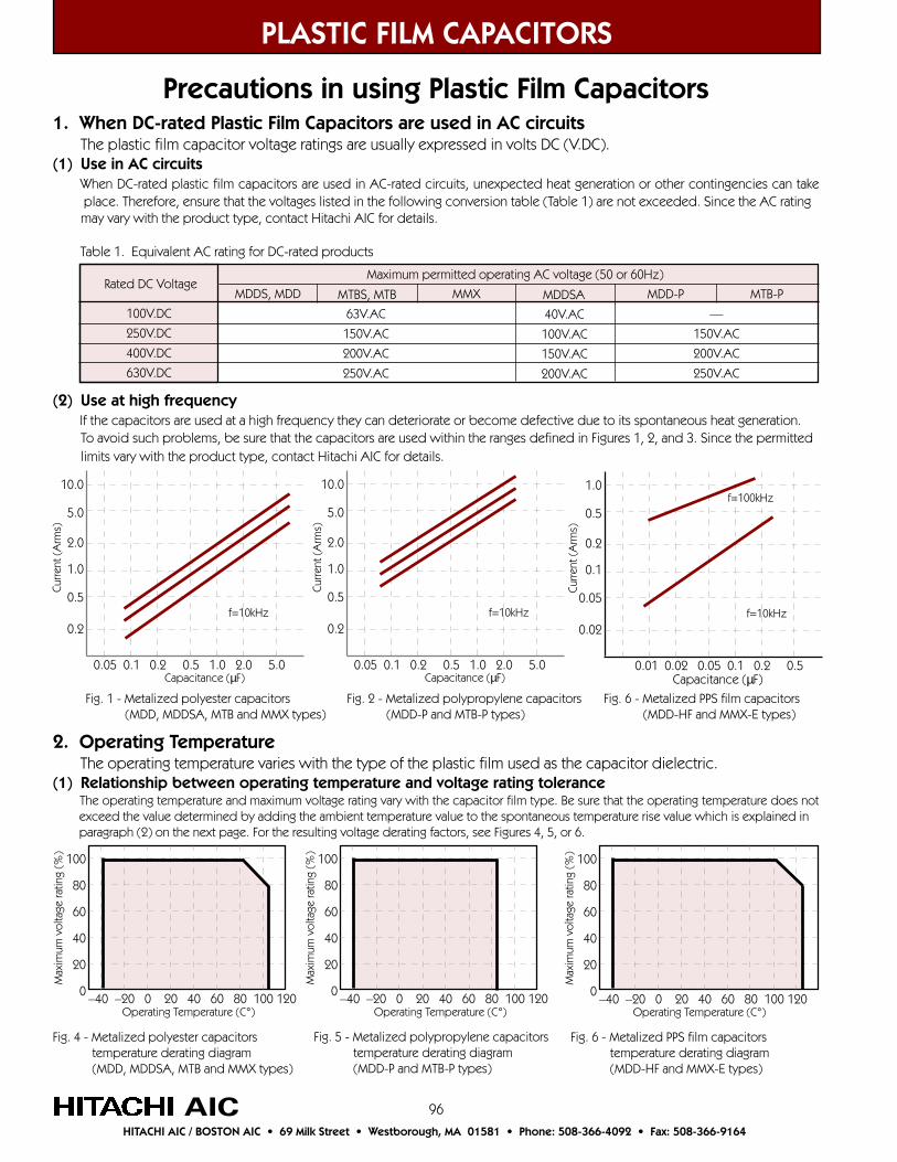
96
PLASTIC FILM CAPACITORS
Precautions in using Plastic Film Capacitors
AICHITACHI AIC / BOSTON AIC • 69 Milk Street • Westborough, MA 01581 • Phone: 508-366-4092 • Fax: 508-366-9164
1. When DC-rated Plastic Film Capacitors are used in AC circuits The plastic film capacitor voltage ratings are usually expressed in volts DC (V.DC).(1) Use in AC circuits When DC-rated plastic film capacitors are used in AC-rated circuits, unexpected heat generation or other contingencies can take place. Therefore, ensure that the voltages listed in the following conversion table (Table 1) are not exceeded. Since the AC rating may vary with the product type, contact Hitachi AIC for details.
Table 1. Equivalent AC rating for DC-rated products
Maximum permitted operating AC voltage (50 or 60Hz)Rated DC Voltage
100V.DC
250V.DC
400V.DC
630V.DC
63V.AC
150V.AC
200V.AC
250V.AC
MDDS, MDD MTBS, MTB MMX MDDSA MDD-P MTB-P
40V.AC
100V.AC
150V.AC
200V.AC
—
150V.AC
200V.AC
250V.AC
(2) Use at high frequency If the capacitors are used at a high frequency they can deteriorate or become defective due to its spontaneous heat generation. To avoid such problems, be sure that the capacitors are used within the ranges defined in Figures 1, 2, and 3. Since the permitted limits vary with the product type, contact Hitachi AIC for details.
2. Operating Temperature The operating temperature varies with the type of the plastic film used as the capacitor dielectric.(1) Relationship between operating temperature and voltage rating tolerance The operating temperature and maximum voltage rating vary with the capacitor film type. Be sure that the operating temperature does not exceed the value determined by adding the ambient temperature value to the spontaneous temperature rise value which is explained in paragraph (2) on the next page. For the resulting voltage derating factors, see Figures 4, 5, or 6.
100
80
60
40
20
0
Max
imum
vol
tage
ratin
g (%
)
–40 –20 0 20 40 60 80 100 120Operating Temperature (C°)
100
80
60
40
20
0
Max
imum
vol
tage
ratin
g (%
)
–40 –20 0 20 40 60 80 100 120Operating Temperature (C°)
100
80
60
40
20
0
Max
imum
vol
tage
ratin
g (%
)
–40 –20 0 20 40 60 80 100 120Operating Temperature (C°)
Fig. 4 - Metalized polyester capacitors temperature derating diagram (MDD, MDDSA, MTB and MMX types)
Fig. 5 - Metalized polypropylene capacitors temperature derating diagram (MDD-P and MTB-P types)
Fig. 6 - Metalized PPS film capacitors temperature derating diagram (MDD-HF and MMX-E types)
10.0
5.0
2.0
1.0
0.5
0.2
0.05 0.1 0.2 0.5 1.0 2.0 5.0
f=10kHz
Capacitance (µF)
Curre
nt (
Arm
s)
10.0
5.0
2.0
1.0
0.5
0.2
0.05 0.1 0.2 0.5 1.0 2.0 5.0
f=10kHz
Capacitance (µF)
Curre
nt (
Arm
s)
1.0
0.5
0.2
0.1
0.05
0.02
0.01 0.02 0.05 0.1 0.2 0.5
f=10kHz
Capacitance (µF)
Curre
nt (
Arm
s)
f=100kHz
Fig. 1 - Metalized polyester capacitors (MDD, MDDSA, MTB and MMX types)
Fig. 2 - Metalized polypropylene capacitors (MDD-P and MTB-P types)
Fig. 6 - Metalized PPS film capacitors (MDD-HF and MMX-E types)
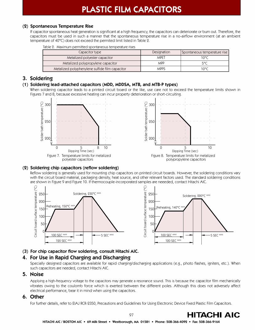
97
PLASTIC FILM CAPACITORS
AICHITACHI AIC / BOSTON AIC • 69 Milk Street • Westborough, MA 01581 • Phone: 508-366-4092 • Fax: 508-366-9164
(2) Spontaneous Temperature Rise If capacitor spontaneous heat generation is significant at a high frequency, the capacitors can deteriorate or burn out. Therefore, the capacitors must be used in such a manner that the spontaneous temperature rise in a no-airflow environment (at an ambient temperature of 40°C) does not exceed the permited limit listed in Table 2.
Spontaneous temperature rise
10°C
5°C
10°C
Designation
MPET
MPP
MPPS
Capacitor type
Metalized polyester capacitor
Metalized polypropylene capacitor
Metalized polyphenylene sulfide film capacitor
Table 2. Maximum permitted spontaneous temperature rises
3. Soldering(1) Soldering lead-attached capacitors (MDD, MDDSA, MTB, and MTB-P types) When soldering capacitor leads to a printed circuit board or the like, use care not to exceed the temperature limits shown in Figures 7 and 8, because excessive heating can incur property deterioration or short-circuiting.
~~
300
250
200
0 5 8 10
Sold
er b
ath
tem
per
atur
e (°
C)
Dipping Time (sec)
Figure 7. Temperature limits for metalizedpolyester capacitors
~~
300
250
200
0 5 10So
lder
bat
h te
mp
erat
ure
(°C)
Dipping Time (sec)
Figure 8. Temperature limits for metalizedpolypropylene capacitors
(2) Soldering chip capacitors (reflow soldering) Reflow soldering is generally used for mounting chip capacitors on printed circuit boards. However, the soldering conditions vary with the circuit board material, packaging density, heat source, and other relevant factors used. The standard soldering conditions are shown in Figure 9 and Figure 10. If thermocouple-incorporated samples are neeeded, contact Hitachi AIC.
Soldering, 230°C MAX
Preheating, 150°C MAX
Circ
uit b
oard
sur
face
tem
per
atur
e (°
C)
250
200
150
100
50
05 SEC MAX100 SEC MAX
120 SEC MAX
Soldering, 220°C MAX
Preheating, 140°C MAX
Circ
uit b
oard
sur
face
tem
per
atur
e (°
C)
250
200
150
100
50
05 SEC MAX100 SEC MAX
120 SEC MAX
(3) For chip capacitor flow soldering, consult Hitachi AIC.4. For Use in Rapid Charging and Discharging Specially designed capacitors are available for rapid charging/discharging applications (e.g., photo flashes, igniters, etc.). When such capacitors are needed, contact Hitachi AIC.
5. Noise Applying a high-frequency voltage to the capacitors may generate a resonance sound. This is because the capacitor film mechanically vibrates owing to the coulomb force which is exerted between the different poles. Although this does not adversely affect electrical performance, bear it in mind when using the capacitors.
6. Other For further details, refer to EIAJ RCR-2350, Precautions and Guidelines for Using Electronic Device Fixed Plastic Film Capacitors.
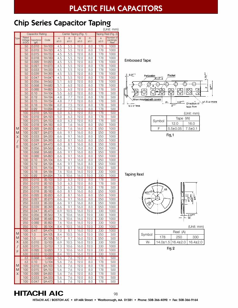
98
05 010.0 301-H1 5.4 5.5 0.21 0.8 871 000105 210.0 321-H1 5.4 5.5 0.21 0.8 871 000105 510.0 351-H1 5.4 5.5 0.21 0.8 871 000105 810.0 381-H1 5.4 5.5 0.21 0.8 871 000105 220.0 322-H1 5.4 5.5 0.21 0.8 871 000105 720.0 372-H1 5.4 5.5 0.21 0.8 871 000105 330.0 333-H1 5.4 5.5 0.21 0.8 871 000105 930.0 393-H1 5.4 5.5 0.21 0.8 871 000105 740.0 740-H1 5.4 5.5 0.21 0.8 871 000105 650.0 365-H1 1.5 2.6 0.21 0.8 871 000105 860.0 386-H1 1.5 2.6 0.21 0.8 871 000105 280.0 328-H1 5.5 2.6 0.21 0.8 871 00505 01.0 401-H1 5.5 2.6 0.21 0.8 871 00505 21.0 421-H1 8.4 7.7 0.21 0.8 871 00505 51.0 451-H1 8.4 7.7 0.21 0.8 871 00505 81.0 481-H1 2.6 5.7 0.21 0.8 871 00505 22.0 422-H1 2.6 5.7 0.21 0.8 871 005001 010.0 301-A2 0.5 3.6 0.21 0.8 871 005001 210.0 321-A2 0.5 3.6 0.21 0.8 871 005001 510.0 351-A2 0.6 3.6 0.21 0.8 871 005001 810.0 381-A2 0.6 6.1 0.61 0.8 052 0001001 220.0 322-A2 0.6 6.1 0.61 0.8 052 0001001 720.0 372-A2 6.6 1.9 0.61 0.8 052 0001001 330.0 333-A2 6.6 1.9 0.61 0.8 052 0001001 930.0 393-A2 0.6 1.8 0.61 0.8 052 0001001 740.0 374-A2 0.6 1.8 0.61 0.8 052 0001001 650.0 365-A2 6.6 1.9 0.61 0.8 052 0001001 860.0 386-A2 6.6 1.9 0.61 0.8 052 0001001 280.0 328-A2 6.6 1.9 0.61 0.8 052 0001001 01.0 401-A2 6.6 1.9 0.61 0.8 052 0001001 21.0 421-A2 6.6 1.9 0.61 0.8 052 0001001 51.0 451-A2 0.7 1.8 0.61 0.21 052 005001 81.0 481-A2 6.7 6.01 0.61 0.21 033 0001001 22.0 422-A2 6.7 6.01 0.61 0.21 033 0001052 010.0 301-E2 0.5 3.6 0.21 0.8 871 005052 210.0 321-E2 0.5 3.6 0.21 0.8 871 005052 510.0 351-E2 0.5 3.6 0.21 0.8 871 005052 810.0 381-E2 0.6 1.8 0.61 0.8 052 0001052 220.0 322-E2 0.6 1.8 0.61 0.8 052 0001052 720.0 372-E2 6.6 1.9 0.61 0.8 052 0001052 330.0 333-E2 6.6 1.9 0.61 0.8 052 0001052 930.0 393-E2 6.6 1.9 0.61 0.8 052 0001052 740.0 374-E2 9.6 5.01 0.61 0.21 033 0001052 650.0 365-E2 6.7 6.01 0.61 0.21 033 0001052 860.0 386-E2 6.7 6.01 0.61 0.21 033 0001052 280.0 328-E2 6.7 6.01 0.61 0.21 033 0001052 01.0 401-E2 4.8 5.01 0.61 0.21 033 0001001 74.0 474-A2 0.7 1.8 0.61 0.21 033 0001001 0.1 501-A2 4.8 5.01 0.61 0.21 052 005061 0.1 501-C2 7.01 7.9 0.61 0.21 052 005036 010.0 301-J2 9.6 5.01 0.61 0.21 033 0001036 510.0 351-J2 3.7 6.01 0.61 0.21 033 0001036 220.0 322-J2 3.7 6.01 0.61 0.21 033 0001036 330.0 333-J2 4.8 5.01 0.61 0.21 033 000136 860.0 386-J1 6.5 6.7 0.21` 0.8 871 00536 01.0 401-J1 6.5 6.7 0.21 0.8 871 005001 010.0 301-A2 6.5 6.7 0.21 0.8 871 005001 510.0 351-A2 6.5 6.7 0.21 0.8 871 005001 220.0 322-A2 6.5 6.7 0.21 0.8 871 005001 330.0 333-A2 6.5 6.7 0.21 0.8 871 005001 740.0 374-A2 6.5 6.7 0.21 0.8 871 005
PLASTIC FILM CAPACITORS
Chip Series Capacitor Taping
AICHITACHI AIC / BOSTON AIC • 69 Milk Street • Westborough, MA 01581 • Phone: 508-366-4092 • Fax: 508-366-9164
MMX/E
MMX/F
MMX
(Unit: mm)
Embossed Tape
Taping Reel
Symbol
F
Tape (W)
12.0 16.05.5±0.05 7.5±0.1
(Unit: mm)
Symbol
W1
Reel (A)
178 250 33014.0±1.5 16.4±2.0 16.4±2.0
(Unit: mm)
Fig,1
Fig.2
Capacitor Rating Carrier Taping (Fig. 1) Taping Reel (Fig. 2)Number ofpackings/
Reel
RatedVoltage(V.DC)
CodeCapacitance(µF)
A±0.3
B±0.3
W±0.3
P1
±0.1A
±2.0Type
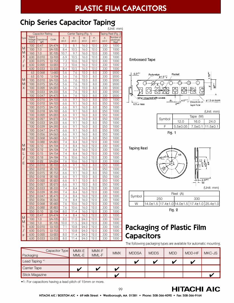
99
PLASTIC FILM CAPACITORS
AICHITACHI AIC / BOSTON AIC • 69 Milk Street • Westborough, MA 01581 • Phone: 508-366-4092 • Fax: 508-366-9164
Packaging of Plastic FilmCapacitors
Capacitor TypePackaging
Lead Taping *1
Carrier Tape
Stick Magazine
MMX MDDSA MDDS MDD MDD-HF MKC-JS
The following packaging types are available for automatic mounting.
•1: For capacitors having a lead pitch of 15mm or more.
MMX-EMML-E
MMX-FMML-F
001 74.0 474-A2 0.7 1.8 0.61 0.21 033 0001001 0.1 501-A2 4.8 5.01 0.61 0.21 033 0001061 0.1 501-C2 7.01 7.9 0.61 0.21 033 0001036 010.0 301-J2 9.6 5.01 0.61 0.21 033 0001036 510.0 351-J2 3.7 6.01 0.61 0.21 033 0001036 220.0 322-J2 3.7 6.01 0.61 0.21 033 0001036 330.0 333-J2 4.8 5.01 0.61 0.21 033 000136 860.0 386-J1 6.5 6.7 0.21 0.8 033 000236 01.0 401-J1 6.5 6.7 0.21 0.8 033 0002001 010.0 301-A2 6.5 6.7 0.21 0.8 033 0002001 510.0 351-A2 6.5 6.7 0.21 0.8 033 0002001 220.0 322-A2 6.5 6.7 0.21 0.8 033 0002001 330.0 333-A2 6.5 6.7 0.21 0.8 033 0002001 740.0 374-A2 6.5 6.7 0.21 0.8 033 0002001 010.0 301-A2 6.6 1.9 0.61 0.8 052 0001001 210.0 321-A2 6.6 1.9 0.61 0.8 052 0001001 510.0 351-A2 6.6 1.9 0.61 0.8 052 0001001 810.0 381-A2 6.6 1.9 0.61 0.8 052 0001001 220.0 322-A2 6.6 1.9 0.61 0.8 052 0001001 720.0 372-A2 6.6 1.9 0.61 0.8 052 0001001 330.0 333-A2 6.6 1.9 0.61 0.8 052 0001001 930.0 393-A2 6.6 1.9 0.61 0.8 052 0001001 740.0 374-A2 6.6 1.9 0.61 0.8 052 0001001 650.0 365-A2 6.6 1.9 0.61 0.8 052 0001001 860.0 386-A2 6.6 1.9 0.61 0.8 052 0001001 280.0 328-A2 4.7 4.8 0.61 0.21 033 0001001 01.0 401-A2 4.7 4.8 0.61 0.21 033 0001001 21.0 421-A2 4.7 4.8 0.61 0.21 033 0001001 51.0 451-A2 4.7 4.8 0.61 0.21 033 0001001 81.0 481-A2 6.7 6.01 0.61 0.21 033 0001001 22.0 422-A2 6.7 6.01 0.61 0.21 033 0001052 010.0 301-E2 6.6 1.9 0.61 0.8 052 0001052 210.0 321-E2 6.6 1.9 0.61 0.8 052 0001052 510.0 351-E2 6.6 1.9 0.61 0.8 052 0001052 810.0 381-E2 6.6 1.9 0.21 0.8 052 0001052 220.0 322-E2 6.6 1.9 0.21 0.8 052 0001052 720.0 372-E2 6.6 1.9 0.21 0.8 052 0001052 330.0 333-E2 4.7 4.8 0.61 0.21 033 0001052 930.0 393-E2 4.7 4.8 0.61 0.21 033 0001052 740.0 374-E2 4.7 4.8 0.61 0.21 033 0001052 650.0 365-E2 4.7 4.8 0.61 0.21 033 0001052 860.0 386-E2 6.7 6.01 0.61 0.21 033 0001052 280.0 328-E2 6.7 6.01 0.61 0.21 033 0001052 01.0 401-E2 0.8 4.11 0.61 0.21 033 0001001 74.0 474-A2 4.7 4.8 0.61 0.21 033 0001001 0.1 501-A2 0.8 0.11 0.42 0.21 033 0001061 0.1 501-C2 0.01 5.11 0.42 0.21 033 0001036 010.0 301-J2 1.7 8.01 0.42 0.21 033 0001036 510.0 351-J2 1.7 8.01 0.42 0.21 033 0001036 220.0 322-J2 0.8 4.11 0.42 0.21 033 0001036 330.0 333-J2 0.8 4.11 0.42 0.21 033 0001
Chip Series Capacitor Taping(Unit: mm)
Embossed Tape
Taping Reel
Symbol
F
Tape (W)
12.0 16.0 24.05.5±0.05 7.5±0.1 11.5±0.1
(Unit: mm)
Symbol
W
Reel (A)
250 33014.0±1.5 17.4±1.0 14.0±1.5 17.4±1.0 25.4±1.0
(Unit: mm)
Fig. 1
Fig. 2
Capacitor Rating Carrier Taping (Fig. 1) Taping Reel (Fig. 2)Number ofpackings/
Reel
RatedVoltage(V.DC)
CodeCapacitance(µF)
A±0.3
B±0.3
W±0.3
P1
±0.1A
±2.0Type
MMX/F
MMX
MML/E
MML/F
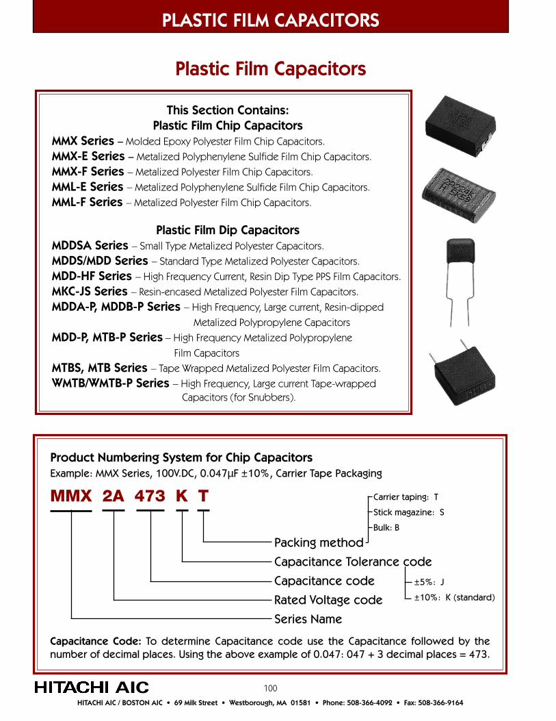
100
This Section Contains:Plastic Film Chip Capacitors
MMX Series – Molded Epoxy Polyester Film Chip Capacitors.
MMX-E Series – Metalized Polyphenylene Sulfide Film Chip Capacitors.
MMX-F Series – Metalized Polyester Film Chip Capacitors.
MML-E Series – Metalized Polyphenylene Sulfide Film Chip Capacitors.
MML-F Series – Metalized Polyester Film Chip Capacitors.
Plastic Film Dip CapacitorsMDDSA Series – Small Type Metalized Polyester Capacitors.
MDDS/MDD Series – Standard Type Metalized Polyester Capacitors.
MDD-HF Series – High Frequency Current, Resin Dip Type PPS Film Capacitors.
MKC-JS Series – Resin-encased Metalized Polyester Film Capacitors.
MDDA-P, MDDB-P Series – High Frequency, Large current, Resin-dipped
Metalized Polypropylene Capacitors
MDD-P, MTB-P Series – High Frequency Metalized Polypropylene
Film Capacitors
MTBS, MTB Series – Tape Wrapped Metalized Polyester Film Capacitors.
WMTB/WMTB-P Series – High Frequency, Large current Tape-wrapped Capacitors (for Snubbers).
Product Numbering System for Chip CapacitorsExample: MMX Series, 100V.DC, 0.047µF ±10%, Carrier Tape Packaging
Packing method
Capacitance Tolerance code
Capacitance code
Rated Voltage code
Series Name
MMX 2A 473 K T
Capacitance Code: To determine Capacitance code use the Capacitance followed by thenumber of decimal places. Using the above example of 0.047: 047 + 3 decimal places = 473.
Carrier taping: T
Stick magazine: S
Bulk: B
±5%: J
±10%: K (standard)
PLASTIC FILM CAPACITORS
AICHITACHI AIC / BOSTON AIC • 69 Milk Street • Westborough, MA 01581 • Phone: 508-366-4092 • Fax: 508-366-9164
Plastic Film Capacitors
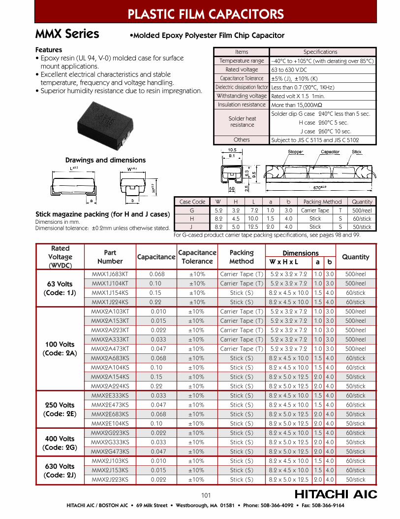
101
PLASTIC FILM CAPACITORSMMX Series •Molded Epoxy Polyester Film Chip Capacitor
AICHITACHI AIC / BOSTON AIC • 69 Milk Street • Westborough, MA 01581 • Phone: 508-366-4092 • Fax: 508-366-9164
Items
Temperature range
Rated voltage
Capacitance Tolerance
Dielectric dissipation factor
Withstanding voltage
Insulation resistance
Others
–40°C to +105°C (with derating over 85°C)
63 to 630 V.DC
±5% (J), ±10% (K)
Less than 0.7 (20°C, 1KHz)
Rated volt X 1.5 1min.
More than 15,000MΩSolder dip G case 240°C less than 5 sec.
H case 260°C 5 sec.
J case 260°C 10 sec.
Subject to JIS C 5115 and JIS C 5102
Specifications
Solder heatresistance
Features• Epoxy resin (UL 94, V-0) molded case for surface mount applications.• Excellent electrical characteristics and stable temperature, frequency and voltage handling.• Superior humidity resistance due to resin impregnation.
Stick magazine packing (for H and J cases)Dimensions in mm.Dimensional tolerance: ±0.2mm unless otherwise stated.
detaRegatloV)CDVW(
traPrebmuN
ecnaticapaCecnaticapaC
ecnareloTgnikcaPdohteM
ytitnauQ
TK386J1XMM 860.0 %01± )T(epaTreirraC 2.7x2.3x2.5 0.1 0.3 leer/005
TK401J1XMM 01.0 %01± )T(epaTreirraC 2.7x2.3x2.5 0.1 0.3 leer/005
SK451J1XMM 51.0 %01± )S(kcitS 0.01x5.4x2.8 5.1 0.4 kcits/06
SK422J1XMM 22.0 %01± )S(kcitS 0.01x5.4x2.8 5.1 0.4 kcits/06
TK301A2XMM 010.0 %01± )T(epaTreirraC 2.7x2.3x2.5 0.1 0.3 leer/005
TK351A2XMM 510.0 %01± )T(epaTreirraC 2.7x2.3x2.5 0.1 0.3 leer/005
TK322A2XMM 220.0 %01± )T(epaTreirraC 2.7x2.3x2.5 0.1 0.3 leer/005
TK333A2XMM 330.0 %01± )T(epaTreirraC 2.7x2.3x2.5 0.1 0.3 leer/005
TK374A2XMM 740.0 %01± )T(epaTreirraC 2.7x2.3x2.5 0.1 0.3 leer/005
SK386A2XMM 860.0 %01± )S(kcitS 0.01x5.4x2.8 5.1 0.4 kcits/06
SK401A2XMM 01.0 %01± )S(kcitS 0.01x5.4x2.8 5.1 0.4 kcits/06
SK451A2XMM 51.0 %01± )S(kcitS 5.21x0.5x2.8 0.2 0.4 kcits/05
SK422A2XMM 22.0 %01± )S(kcitS 5.21x0.5x2.8 0.2 0.4 kcits/05
SK333E2XMM 330.0 %01± )S(kcitS 0.01x5.4x2.8 5.1 0.4 kcits/06
SK374E2XMM 740.0 %01± )S(kcitS 0.01x5.4x2.8 5.1 0.4 kcits/06
SK386E2XMM 860.0 %01± )S(kcitS 5.21x0.5x2.8 0.2 0.4 kcits/05
SK401E2XMM 01.0 %01± )S(kcitS 5.21x0.5x2.8 0.2 0.4 kcits/05
SK322G2XMM 220.0 %01± )S(kcitS 0.01x5.4x2.8 5.1 0.4 kcits/06
SK333G2XMM 330.0 %01± )S(kcitS 5.21x0.5x2.8 0.2 0.4 kcits/05
SK374G2XMM 740.0 %01± )S(kcitS 5.21x0.5x2.8 0.2 0.4 kcits/05
SK301J2XMM 010.0 %01± )S(kcitS 0.01x5.4x2.8 5.1 0.4 kcits/06
SK351J2XMM 510.0 %01± )S(kcitS 0.01x5.4x2.8 5.1 0.4 kcits/06
SK322J2XMM 220.0 %01± )S(kcitS 5.21x0.5x2.8 0.2 0.4 kcits/05
63 Volts(Code: 1J)
100 Volts(Code: 2A)
250 Volts(Code: 2E)
400 Volts(Code: 2G)
630 Volts(Code: 2J)
DimensionsW x H x L a b
GHJ
5.28.28.2
3.24.55.0
7.210.012.5
1.01.52.0
3.04.04.0
Carrier TapeStickStick
TSS
500/reel60/stick50/stick
Case Code W H L a b Packing Method Quantity
For G-cased product carrier tape packing specifications, see pages 98 and 99.
Drawings and dimensions
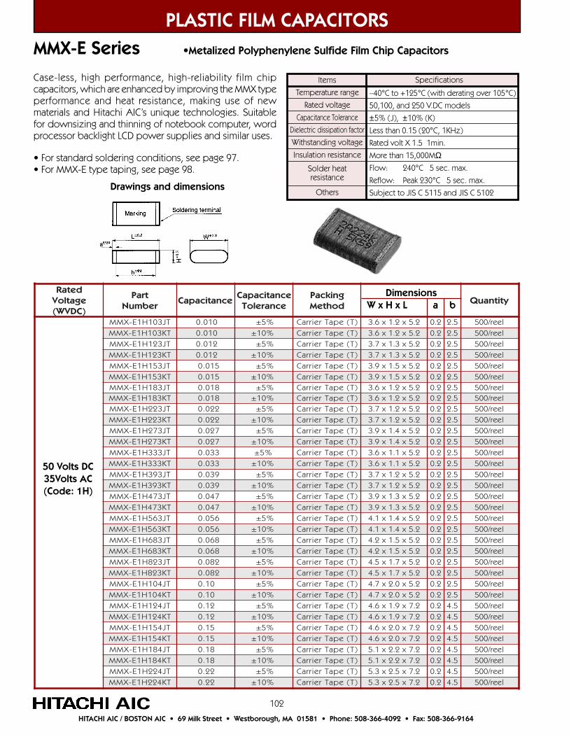
102
PLASTIC FILM CAPACITORSMMX-E Series •Metalized Polyphenylene Sulfide Film Chip Capacitors
AICHITACHI AIC / BOSTON AIC • 69 Milk Street • Westborough, MA 01581 • Phone: 508-366-4092 • Fax: 508-366-9164
Items
Temperature range
Rated voltage
Capacitance Tolerance
Dielectric dissipation factor
Withstanding voltage
Insulation resistance
Others
–40°C to +125°C (with derating over 105°C)
50,100, and 250 V.DC models
±5% (J), ±10% (K)
Less than 0.15 (20°C, 1KHz)
Rated volt X 1.5 1min.
More than 15,000MΩFlow: 240°C 5 sec. max.
Reflow: Peak 230°C 5 sec. max.
Subject to JIS C 5115 and JIS C 5102
Specifications
Solder heatresistance
Case-less, high performance, high-reliability film chipcapacitors, which are enhanced by improving the MMX typeperformance and heat resistance, making use of newmaterials and Hitachi AIC’s unique technologies. Suitablefor downsizing and thinning of notebook computer, wordprocessor backlight LCD power supplies and similar uses.
detaRegatloV)CDVW(
traPrebmuN
ecnaticapaCecnaticapaC
ecnareloTgnikcaPdohteM
ytitnauQ
TJ301H1E-XMM 010.0 %5± )T(epaTreirraC 2.5x2.1x6.3 2.0 5.2 leer/005TK301H1E-XMM 010.0 %01± )T(epaTreirraC 2.5x2.1x6.3 2.0 5.2 leer/005TJ321H1E-XMM 210.0 %5± )T(epaTreirraC 2.5x3.1x7.3 2.0 5.2 leer/005TK321H1E-XMM 210.0 %01± )T(epaTreirraC 2.5x3.1x7.3 2.0 5.2 leer/005TJ351H1E-XMM 510.0 %5± )T(epaTreirraC 2.5x5.1x9.3 2.0 5.2 leer/005TK351H1E-XMM 510.0 %01± )T(epaTreirraC 2.5x5.1x9.3 2.0 5.2 leer/005TJ381H1E-XMM 810.0 %5± )T(epaTreirraC 2.5x2.1x6.3 2.0 5.2 leer/005TK381H1E-XMM 810.0 %01± )T(epaTreirraC 2.5x2.1x6.3 2.0 5.2 leer/005TJ322H1E-XMM 220.0 %5± )T(epaTreirraC 2.5x2.1x7.3 2.0 5.2 leer/005TK322H1E-XMM 220.0 %01± )T(epaTreirraC 2.5x2.1x7.3 2.0 5.2 leer/005TJ372H1E-XMM 720.0 %5± )T(epaTreirraC 2.5x4.1x9.3 2.0 5.2 leer/005TK372H1E-XMM 720.0 %01± )T(epaTreirraC 2.5x4.1x9.3 2.0 5.2 leer/005TJ333H1E-XMM 330.0 %5± )T(epaTreirraC 2.5x1.1x6.3 2.0 5.2 leer/005TK333H1E-XMM 330.0 %01± )T(epaTreirraC 2.5x1.1x6.3 2.0 5.2 leer/005TJ393H1E-XMM 930.0 %5± )T(epaTreirraC 2.5x2.1x7.3 2.0 5.2 leer/005TK393H1E-XMM 930.0 %01± )T(epaTreirraC 2.5x2.1x7.3 2.0 5.2 leer/005TJ374H1E-XMM 740.0 %5± )T(epaTreirraC 2.5x3.1x9.3 2.0 5.2 leer/005TK374H1E-XMM 740.0 %01± )T(epaTreirraC 2.5x3.1x9.3 2.0 5.2 leer/005TJ365H1E-XMM 650.0 %5± )T(epaTreirraC 2.5x4.1x1.4 2.0 5.2 leer/005TK365H1E-XMM 650.0 %01± )T(epaTreirraC 2.5x4.1x1.4 2.0 5.2 leer/005TJ386H1E-XMM 860.0 %5± )T(epaTreirraC 2.5x5.1x2.4 2.0 5.2 leer/005TK386H1E-XMM 860.0 %01± )T(epaTreirraC 2.5x5.1x2.4 2.0 5.2 leer/005TJ328H1E-XMM 280.0 %5± )T(epaTreirraC 2.5x7.1x5.4 2.0 5.2 leer/005TK328H1E-XMM 280.0 %01± )T(epaTreirraC 2.5x7.1x5.4 2.0 5.2 leer/005TJ401H1E-XMM 01.0 %5± )T(epaTreirraC 2.5x0.2x7.4 2.0 5.2 leer/005TK401H1E-XMM 01.0 %01± )T(epaTreirraC 2.5x0.2x7.4 2.0 5.2 leer/005TJ421H1E-XMM 21.0 %5± )T(epaTreirraC 2.7x9.1x6.4 2.0 5.4 leer/005TK421H1E-XMM 21.0 %01± )T(epaTreirraC 2.7x9.1x6.4 2.0 5.4 leer/005TJ451H1E-XMM 51.0 %5± )T(epaTreirraC 2.7x0.2x6.4 2.0 5.4 leer/005TK451H1E-XMM 51.0 %01± )T(epaTreirraC 2.7x0.2x6.4 2.0 5.4 leer/005TJ481H1E-XMM 81.0 %5± )T(epaTreirraC 2.7x2.2x1.5 2.0 5.4 leer/005TK481H1E-XMM 81.0 %01± )T(epaTreirraC 2.7x2.2x1.5 2.0 5.4 leer/005TJ422H1E-XMM 22.0 %5± )T(epaTreirraC 2.7x5.2x3.5 2.0 5.4 leer/005TK422H1E-XMM 22.0 %01± )T(epaTreirraC 2.7x5.2x3.5 2.0 5.4 leer/005
Drawings and dimensions
DimensionsW x H x L a b
50 Volts DC35Volts AC(Code: 1H)
• For standard soldering conditions, see page 97.• For MMX-E type taping, see page 98.
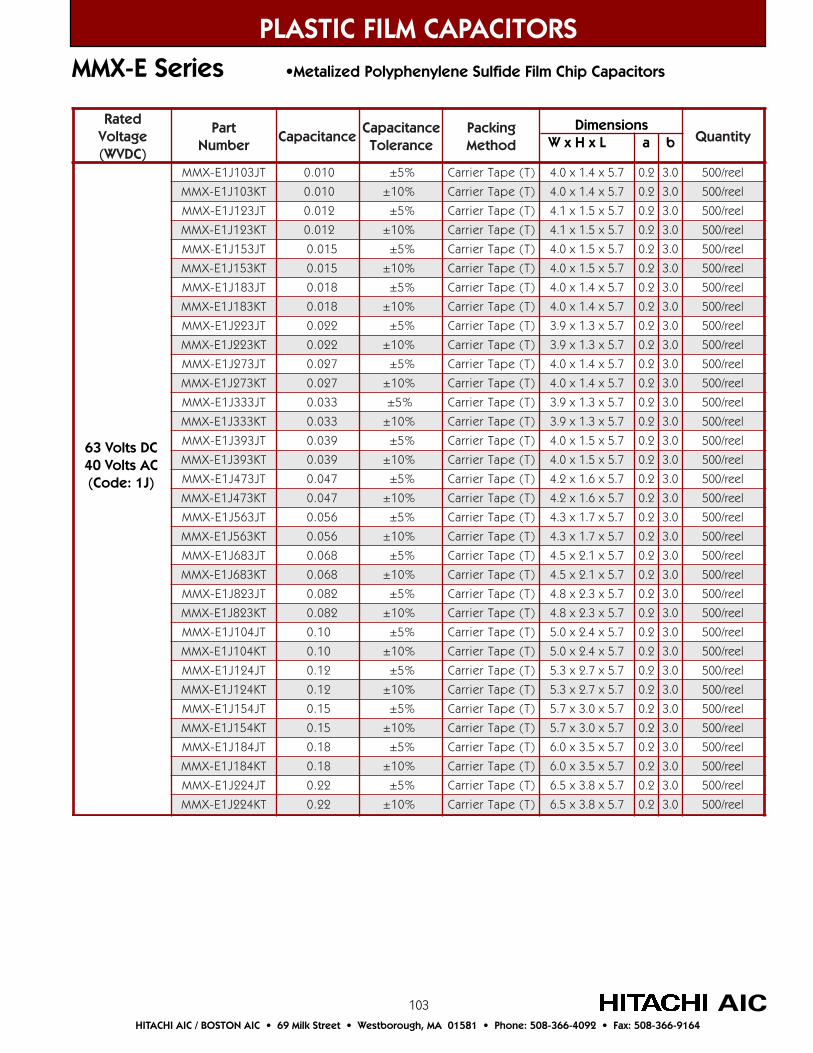
103
detaRegatloV)CDVW(
traPrebmuN
ecnaticapaCecnaticapaC
ecnareloTgnikcaPdohteM
ytitnauQ
TJ301J1E-XMM 010.0 %5± )T(epaTreirraC 7.5x4.1x0.4 2.0 0.3 leer/005
TK301J1E-XMM 010.0 %01± )T(epaTreirraC 7.5x4.1x0.4 2.0 0.3 leer/005
TJ321J1E-XMM 210.0 %5± )T(epaTreirraC 7.5x5.1x1.4 2.0 0.3 leer/005
TK321J1E-XMM 210.0 %01± )T(epaTreirraC 7.5x5.1x1.4 2.0 0.3 leer/005
TJ351J1E-XMM 510.0 %5± )T(epaTreirraC 7.5x5.1x0.4 2.0 0.3 leer/005
TK351J1E-XMM 510.0 %01± )T(epaTreirraC 7.5x5.1x0.4 2.0 0.3 leer/005
TJ381J1E-XMM 810.0 %5± )T(epaTreirraC 7.5x4.1x0.4 2.0 0.3 leer/005
TK381J1E-XMM 810.0 %01± )T(epaTreirraC 7.5x4.1x0.4 2.0 0.3 leer/005
TJ322J1E-XMM 220.0 %5± )T(epaTreirraC 7.5x3.1x9.3 2.0 0.3 leer/005
TK322J1E-XMM 220.0 %01± )T(epaTreirraC 7.5x3.1x9.3 2.0 0.3 leer/005
TJ372J1E-XMM 720.0 %5± )T(epaTreirraC 7.5x4.1x0.4 2.0 0.3 leer/005
TK372J1E-XMM 720.0 %01± )T(epaTreirraC 7.5x4.1x0.4 2.0 0.3 leer/005
TJ333J1E-XMM 330.0 %5± )T(epaTreirraC 7.5x3.1x9.3 2.0 0.3 leer/005
TK333J1E-XMM 330.0 %01± )T(epaTreirraC 7.5x3.1x9.3 2.0 0.3 leer/005
TJ393J1E-XMM 930.0 %5± )T(epaTreirraC 7.5x5.1x0.4 2.0 0.3 leer/005
TK393J1E-XMM 930.0 %01± )T(epaTreirraC 7.5x5.1x0.4 2.0 0.3 leer/005
TJ374J1E-XMM 740.0 %5± )T(epaTreirraC 7.5x6.1x2.4 2.0 0.3 leer/005
TK374J1E-XMM 740.0 %01± )T(epaTreirraC 7.5x6.1x2.4 2.0 0.3 leer/005
TJ365J1E-XMM 650.0 %5± )T(epaTreirraC 7.5x7.1x3.4 2.0 0.3 leer/005
TK365J1E-XMM 650.0 %01± )T(epaTreirraC 7.5x7.1x3.4 2.0 0.3 leer/005
TJ386J1E-XMM 860.0 %5± )T(epaTreirraC 7.5x1.2x5.4 2.0 0.3 leer/005
TK386J1E-XMM 860.0 %01± )T(epaTreirraC 7.5x1.2x5.4 2.0 0.3 leer/005
TJ328J1E-XMM 280.0 %5± )T(epaTreirraC 7.5x3.2x8.4 2.0 0.3 leer/005
TK328J1E-XMM 280.0 %01± )T(epaTreirraC 7.5x3.2x8.4 2.0 0.3 leer/005
TJ401J1E-XMM 01.0 %5± )T(epaTreirraC 7.5x4.2x0.5 2.0 0.3 leer/005
TK401J1E-XMM 01.0 %01± )T(epaTreirraC 7.5x4.2x0.5 2.0 0.3 leer/005
TJ421J1E-XMM 21.0 %5± )T(epaTreirraC 7.5x7.2x3.5 2.0 0.3 leer/005
TK421J1E-XMM 21.0 %01± )T(epaTreirraC 7.5x7.2x3.5 2.0 0.3 leer/005
TJ451J1E-XMM 51.0 %5± )T(epaTreirraC 7.5x0.3x7.5 2.0 0.3 leer/005
TK451J1E-XMM 51.0 %01± )T(epaTreirraC 7.5x0.3x7.5 2.0 0.3 leer/005
TJ481J1E-XMM 81.0 %5± )T(epaTreirraC 7.5x5.3x0.6 2.0 0.3 leer/005
TK481J1E-XMM 81.0 %01± )T(epaTreirraC 7.5x5.3x0.6 2.0 0.3 leer/005
TJ422J1E-XMM 22.0 %5± )T(epaTreirraC 7.5x8.3x5.6 2.0 0.3 leer/005
TK422J1E-XMM 22.0 %01± )T(epaTreirraC 7.5x8.3x5.6 2.0 0.3 leer/005
PLASTIC FILM CAPACITORS
AICHITACHI AIC / BOSTON AIC • 69 Milk Street • Westborough, MA 01581 • Phone: 508-366-4092 • Fax: 508-366-9164
MMX-E Series •Metalized Polyphenylene Sulfide Film Chip Capacitors
DimensionsW x H x L a b
63 Volts DC40 Volts AC(Code: 1J)
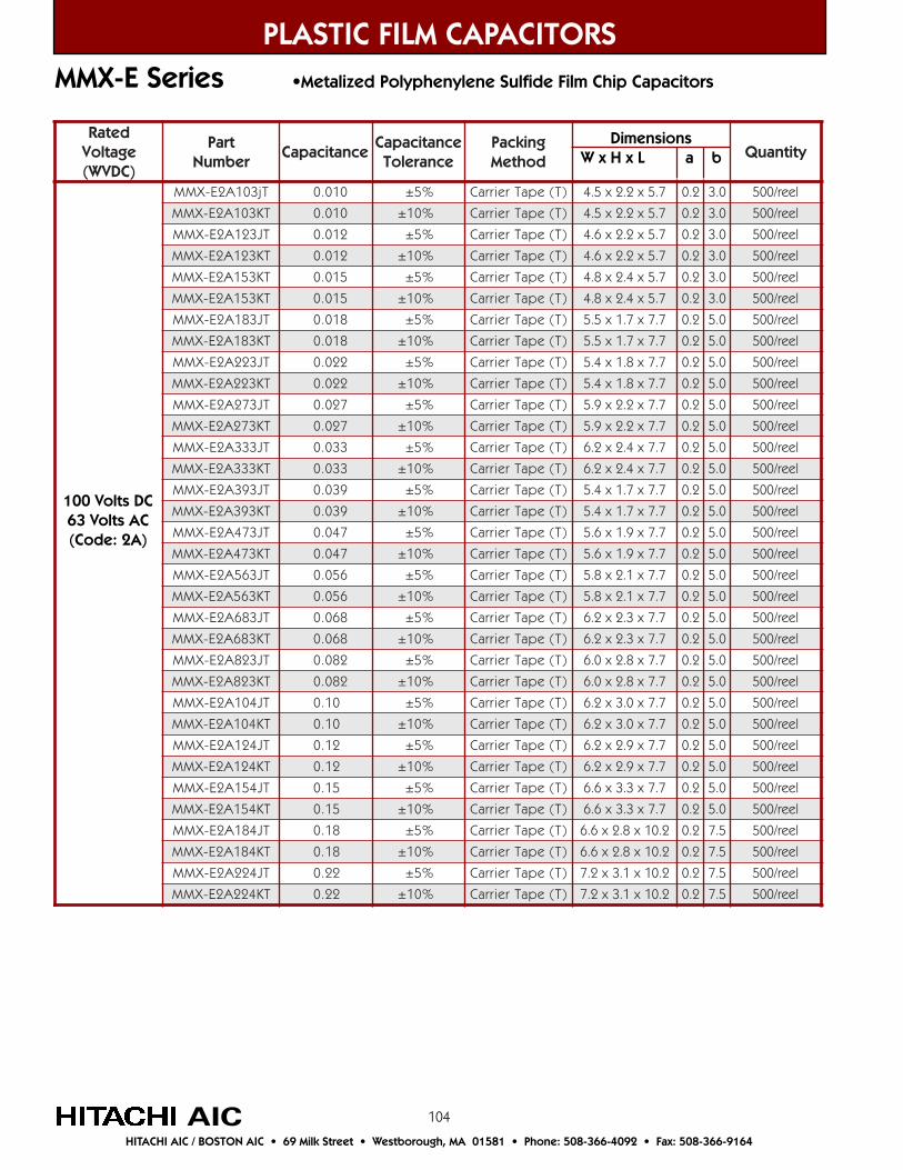
104
detaRegatloV)CDVW(
traPrebmuN
ecnaticapaCecnaticapaC
ecnareloTgnikcaPdohteM
ytitnauQ
Tj301A2E-XMM 010.0 %5± )T(epaTreirraC 7.5x2.2x5.4 2.0 0.3 leer/005
TK301A2E-XMM 010.0 %01± )T(epaTreirraC 7.5x2.2x5.4 2.0 0.3 leer/005
TJ321A2E-XMM 210.0 %5± )T(epaTreirraC 7.5x2.2x6.4 2.0 0.3 leer/005
TK321A2E-XMM 210.0 %01± )T(epaTreirraC 7.5x2.2x6.4 2.0 0.3 leer/005
TK351A2E-XMM 510.0 %5± )T(epaTreirraC 7.5x4.2x8.4 2.0 0.3 leer/005
TK351A2E-XMM 510.0 %01± )T(epaTreirraC 7.5x4.2x8.4 2.0 0.3 leer/005
TJ381A2E-XMM 810.0 %5± )T(epaTreirraC 7.7x7.1x5.5 2.0 0.5 leer/005
TK381A2E-XMM 810.0 %01± )T(epaTreirraC 7.7x7.1x5.5 2.0 0.5 leer/005
TJ322A2E-XMM 220.0 %5± )T(epaTreirraC 7.7x8.1x4.5 2.0 0.5 leer/005
TK322A2E-XMM 220.0 %01± )T(epaTreirraC 7.7x8.1x4.5 2.0 0.5 leer/005
TJ372A2E-XMM 720.0 %5± )T(epaTreirraC 7.7x2.2x9.5 2.0 0.5 leer/005
TK372A2E-XMM 720.0 %01± )T(epaTreirraC 7.7x2.2x9.5 2.0 0.5 leer/005
TJ333A2E-XMM 330.0 %5± )T(epaTreirraC 7.7x4.2x2.6 2.0 0.5 leer/005
TK333A2E-XMM 330.0 %01± )T(epaTreirraC 7.7x4.2x2.6 2.0 0.5 leer/005
TJ393A2E-XMM 930.0 %5± )T(epaTreirraC 7.7x7.1x4.5 2.0 0.5 leer/005
TK393A2E-XMM 930.0 %01± )T(epaTreirraC 7.7x7.1x4.5 2.0 0.5 leer/005
TJ374A2E-XMM 740.0 %5± )T(epaTreirraC 7.7x9.1x6.5 2.0 0.5 leer/005
TK374A2E-XMM 740.0 %01± )T(epaTreirraC 7.7x9.1x6.5 2.0 0.5 leer/005
TJ365A2E-XMM 650.0 %5± )T(epaTreirraC 7.7x1.2x8.5 2.0 0.5 leer/005
TK365A2E-XMM 650.0 %01± )T(epaTreirraC 7.7x1.2x8.5 2.0 0.5 leer/005
TJ386A2E-XMM 860.0 %5± )T(epaTreirraC 7.7x3.2x2.6 2.0 0.5 leer/005
TK386A2E-XMM 860.0 %01± )T(epaTreirraC 7.7x3.2x2.6 2.0 0.5 leer/005
TJ328A2E-XMM 280.0 %5± )T(epaTreirraC 7.7x8.2x0.6 2.0 0.5 leer/005
TK328A2E-XMM 280.0 %01± )T(epaTreirraC 7.7x8.2x0.6 2.0 0.5 leer/005
TJ401A2E-XMM 01.0 %5± )T(epaTreirraC 7.7x0.3x2.6 2.0 0.5 leer/005
TK401A2E-XMM 01.0 %01± )T(epaTreirraC 7.7x0.3x2.6 2.0 0.5 leer/005
TJ421A2E-XMM 21.0 %5± )T(epaTreirraC 7.7x9.2x2.6 2.0 0.5 leer/005
TK421A2E-XMM 21.0 %01± )T(epaTreirraC 7.7x9.2x2.6 2.0 0.5 leer/005
TJ451A2E-XMM 51.0 %5± )T(epaTreirraC 7.7x3.3x6.6 2.0 0.5 leer/005
TK451A2E-XMM 51.0 %01± )T(epaTreirraC 7.7x3.3x6.6 2.0 0.5 leer/005
TJ481A2E-XMM 81.0 %5± )T(epaTreirraC 2.01x8.2x6.6 2.0 5.7 leer/005
TK481A2E-XMM 81.0 %01± )T(epaTreirraC 2.01x8.2x6.6 2.0 5.7 leer/005
TJ422A2E-XMM 22.0 %5± )T(epaTreirraC 2.01x1.3x2.7 2.0 5.7 leer/005
TK422A2E-XMM 22.0 %01± )T(epaTreirraC 2.01x1.3x2.7 2.0 5.7 leer/005
PLASTIC FILM CAPACITORS
AICHITACHI AIC / BOSTON AIC • 69 Milk Street • Westborough, MA 01581 • Phone: 508-366-4092 • Fax: 508-366-9164
MMX-E Series •Metalized Polyphenylene Sulfide Film Chip Capacitors
DimensionsW x H x L a b
100 Volts DC63 Volts AC(Code: 2A)
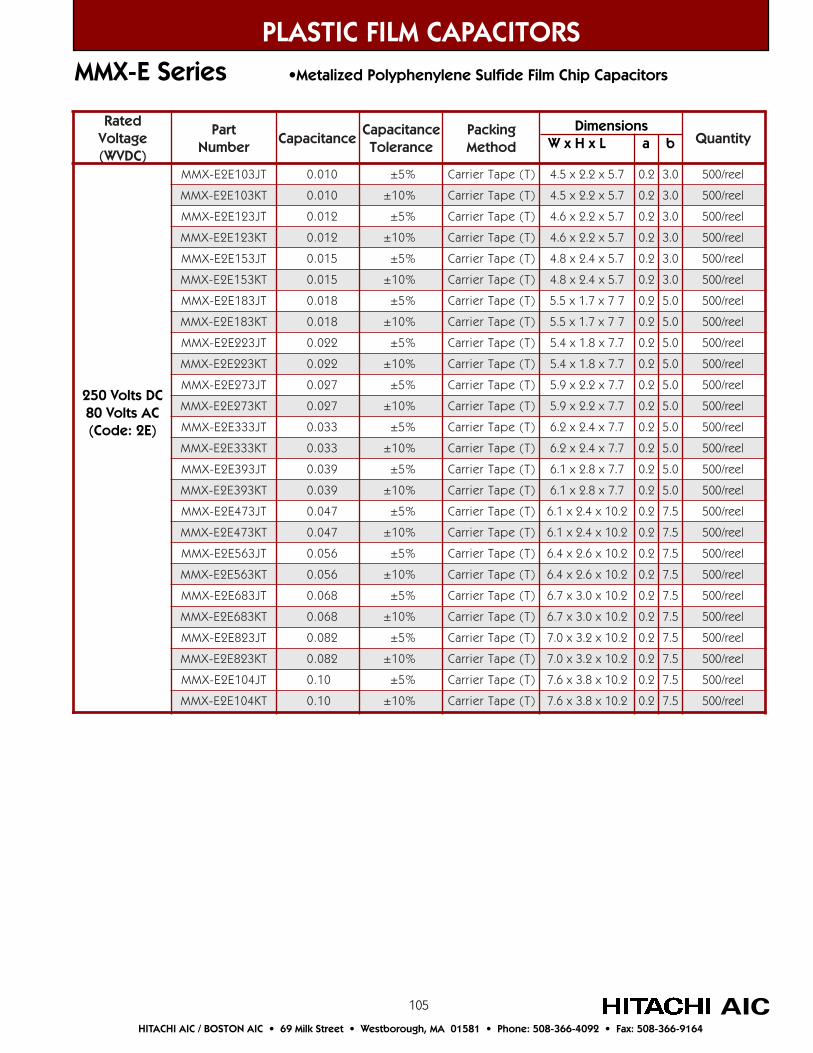
105
250 Volts DC80 Volts AC(Code: 2E)
PLASTIC FILM CAPACITORS
AICHITACHI AIC / BOSTON AIC • 69 Milk Street • Westborough, MA 01581 • Phone: 508-366-4092 • Fax: 508-366-9164
MMX-E Series •Metalized Polyphenylene Sulfide Film Chip Capacitors
detaRegatloV)CDVW(
traPrebmuN
ecnaticapaCecnaticapaC
ecnareloTgnikcaPdohteM
ytitnauQ
TJ301E2E-XMM 010.0 %5± )T(epaTreirraC 7.5x2.2x5.4 2.0 0.3 leer/005
TK301E2E-XMM 010.0 %01± )T(epaTreirraC 7.5x2.2x5.4 2.0 0.3 leer/005
TJ321E2E-XMM 210.0 %5± )T(epaTreirraC 7.5x2.2x6.4 2.0 0.3 leer/005
TK321E2E-XMM 210.0 %01± )T(epaTreirraC 7.5x2.2x6.4 2.0 0.3 leer/005
TJ351E2E-XMM 510.0 %5± )T(epaTreirraC 7.5x4.2x8.4 2.0 0.3 leer/005
TK351E2E-XMM 510.0 %01± )T(epaTreirraC 7.5x4.2x8.4 2.0 0.3 leer/005
TJ381E2E-XMM 810.0 %5± )T(epaTreirraC 77x7.1x5.5 2.0 0.5 leer/005
TK381E2E-XMM 810.0 %01± )T(epaTreirraC 77x7.1x5.5 2.0 0.5 leer/005
TJ322E2E-XMM 220.0 %5± )T(epaTreirraC 7.7x8.1x4.5 2.0 0.5 leer/005
TK322E2E-XMM 220.0 %01± )T(epaTreirraC 7.7x8.1x4.5 2.0 0.5 leer/005
TJ372E2E-XMM 720.0 %5± )T(epaTreirraC 7.7x2.2x9.5 2.0 0.5 leer/005
TK372E2E-XMM 720.0 %01± )T(epaTreirraC 7.7x2.2x9.5 2.0 0.5 leer/005
TJ333E2E-XMM 330.0 %5± )T(epaTreirraC 7.7x4.2x2.6 2.0 0.5 leer/005
TK333E2E-XMM 330.0 %01± )T(epaTreirraC 7.7x4.2x2.6 2.0 0.5 leer/005
TJ393E2E-XMM 930.0 %5± )T(epaTreirraC 7.7x8.2x1.6 2.0 0.5 leer/005
TK393E2E-XMM 930.0 %01± )T(epaTreirraC 7.7x8.2x1.6 2.0 0.5 leer/005
TJ374E2E-XMM 740.0 %5± )T(epaTreirraC 2.01x4.2x1.6 2.0 5.7 leer/005
TK374E2E-XMM 740.0 %01± )T(epaTreirraC 2.01x4.2x1.6 2.0 5.7 leer/005
TJ365E2E-XMM 650.0 %5± )T(epaTreirraC 2.01x6.2x4.6 2.0 5.7 leer/005
TK365E2E-XMM 650.0 %01± )T(epaTreirraC 2.01x6.2x4.6 2.0 5.7 leer/005
TJ386E2E-XMM 860.0 %5± )T(epaTreirraC 2.01x0.3x7.6 2.0 5.7 leer/005
TK386E2E-XMM 860.0 %01± )T(epaTreirraC 2.01x0.3x7.6 2.0 5.7 leer/005
TJ328E2E-XMM 280.0 %5± )T(epaTreirraC 2.01x2.3x0.7 2.0 5.7 leer/005
TK328E2E-XMM 280.0 %01± )T(epaTreirraC 2.01x2.3x0.7 2.0 5.7 leer/005
TJ401E2E-XMM 01.0 %5± )T(epaTreirraC 2.01x8.3x6.7 2.0 5.7 leer/005
TK401E2E-XMM 01.0 %01± )T(epaTreirraC 2.01x8.3x6.7 2.0 5.7 leer/005
DimensionsW x H x L a b
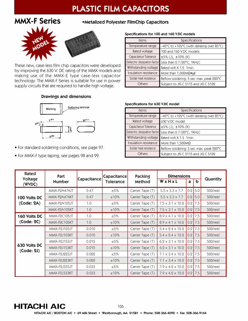
106
detaRegatloV)CDVW(
traPrebmuN
ecnaticapaCecnaticapaC
ecnareloTgnikcaPdohteM
ytitnauQ
TJ474A2F-XMM 74.0 %5± )T(epaTreirraC 7.7x3.3x5.5 2.0 0.5 leer/005
TK474A2F-XMM 74.0 %01± )T(epaTreirraC 7.7x3.3x5.5 2.0 0.5 leer/005
TJ501A2F-XMM 0.1 %5± )T(epaTreirraC 2.01x1.3x5.7 2.0 5.7 leer/005
TK501A2F-XMM 0.1 %01± )T(epaTreirraC 2.01x1.3x5.7 2.0 5.7 leer/005
TJ501C2F-XMM 0.1 %5± )T(epaTreirraC 2.01x1.4x9.8 2.0 5.7 leer/005
TK501C2F-XMM 0.1 %01± )T(epaTreirraC 2.01x1.4x9.8 2.0 5.7 leer/005
TJ301J2F-XMM 010.0 %5± )T(epaTreirraC 2.01x4.2x4.5 2.0 5.7 leer/005
TK301J2F-XMM 010.0 %01± )T(epaTreirraC 2.01x4.2x4.5 2.0 5.7 leer/005
TJ351J2F-XMM 510.0 %5± )T(epaTreirraC 2.01x1.3x2.6 2.0 5.7 leer/005
TK351J2F-XMM 510.0 %01± )T(epaTreirraC 2.01x1.3x2.6 2.0 5.7 leer/005
TJ322J2F-XMM 220.0 %5± )T(epaTreirraC 2.01x4.3x1.7 2.0 5.7 leer/005
TK322J2F-XMM 220.0 %01± )T(epaTreirraC 2.01x4.3x1.7 2.0 5.7 leer/005
TJ333J2F-XMM 330.0 %5± )T(epaTreirraC 2.01x2.4x9.7 2.0 5.7 leer/005
TK333J2F-XMM 330.0 %01± )T(epaTreirraC 2.01x2.4x9.7 2.0 5.7 leer/005
PLASTIC FILM CAPACITORSMMX-F Series •Metalized Polyester FilmChip Capacitors
AICHITACHI AIC / BOSTON AIC • 69 Milk Street • Westborough, MA 01581 • Phone: 508-366-4092 • Fax: 508-366-9164
NEW
MODEL
These new, case-less film chip capacitors were developedby improving the 630 V. DC rating of the MMX models andmaking use of the MMX-E type case-less capacitortechnology. The MMX-F Series is suitable for use in powersupply circuits that are required to handle high voltage.
Items
Temperature range
Rated voltage
Capacitance Tolerance
Dielectric dissipation factor
Withstanding voltage
Insulation resistance
Solder heat resistance
Others
–40°C to +105°C (with derating over 85°C)
100 and 160 V.DC models
±5% (J), ±10% (K)
Less than 0.7 (20°C, 1KHz)
Rated volt X 1.5 1min.
More than 1,000MΩ•µF
Reflow soldering: 5 sec max. peak 220°C
Subject to JIS C 5115 and JIS C 5102
Specifications
Items
Temperature range
Rated voltage
Capacitance Tolerance
Dielectric dissipation factor
Withstanding voltage
Insulation resistance
Solder heat resistance
Others
–40°C to +105°C (with derating over 85°C)
630 V.DC model
±5% (J), ±10% (K)
Less than 0.7 (20°C, 1KHz)
Rated volt X 1.5 1min.
More than 1,500MΩReflow soldering: 5 sec max. peak 220°C
Subject to JIS C 5115 and JIS C 5102
Specifications
Specifications for 100 and 160 V.DC models
Specifications for 630 V.DC model
Drawings and dimensions
• For standard soldering conditions, see page 97.
• For MMX-F type taping, see pages 98 and 99.
DimensionsW x H x L a b
100 Volts DC(Code: 2A)
630 Volts DC(Code: 2J)
160 Volts DC(Code: 2C)

107
PLASTIC FILM CAPACITORSMML-E Series •Metalized Polyphenylene Sulfide Film Chip Capacitors
AICHITACHI AIC / BOSTON AIC • 69 Milk Street • Westborough, MA 01581 • Phone: 508-366-4092 • Fax: 508-366-9164
detaRegatloV)CDVW(
traPrebmuN
ecnaticapaCecnaticapaC
ecnareloTgnikcaPdohteM
ytitnauQ
TJ301A2E-LMM 010.0 %5± )T(epaTreirraC 9.7x5.2x4.5 2.1 8.4 3.4 3.0 leer/005TK301A2E-LMM 010.0 %01± )T(epaTreirraC 9.7x5.2x4.5 2.1 8.4 3.4 3.0 leer/005TJ321A2E-LMM 210.1 %5± )T(epaTreirraC 9.7x5.2x5.5 2.1 8.4 3.4 3.0 leer/005TK321A2E-LMM 210.1 %01± )T(epaTreirraC 9.7x5.2x5.5 2.1 8.4 3.4 3.0 leer/005TJ351A2E-LMM 510.1 %5± )T(epaTreirraC 9.7x5.2x4.5 2.1 8.4 3.4 3.0 leer/005TK351A2E-LMM 510.1 %01± )T(epaTreirraC 9.7x5.2x4.5 2.1 8.4 3.4 3.0 leer/005TJ381A2E-LMM 810.0 %5± )T(epaTreirraC 9.7x5.2x5.5 2.1 8.4 3.4 3.0 leer/005TK381A2E-LMM 810.0 %01± )T(epaTreirraC 9.7x5.2x5.5 2.1 8.4 3.4 3.0 leer/005TJ322A2E-LMM 220.0 %5± )T(epaTreirraC 9.7x5.2x5.5 2.1 8.4 3.4 3.0 leer/005TK322A2E-LMM 220.0 %01± )T(epaTreirraC 9.7x5.2x5.5 2.1 8.4 3.4 3.0 leer/005TJ372A2E-LMM 720.0 %5± )T(epaTreirraC 9.7x5.2x7.5 2.1 8.4 3.4 3.0 leer/005TK372A2E-LMM 720.0 %01± )T(epaTreirraC 9.7x5.2x7.5 2.1 8.4 3.4 3.0 leer/005TJ333A2E-LMM 330.0 %5± )T(epaTreirraC 9.7x5.2x5.5 2.1 3.7 3.4 3.0 leer/005TK333A2E-LMM 330.0 %01± )T(epaTreirraC 9.7x5.2x5.5 2.1 3.7 3.4 3.0 leer/005TJ393A2E-LMM 930.0 %5± )T(epaTreirraC 9.7x5.2x7.5 2.1 8.4 3.4 3.0 leer/005TK393A2E-LMM 930.0 %01± )T(epaTreirraC 9.7x5.2x7.5 2.1 8.4 3.4 3.0 leer/005TJ374A2E-LMM 740.0 %5± )T(epaTreirraC 9.7x5.2x4.5 2.1 8.4 3.4 3.0 leer/005TK374A2E-LMM 740.0 %01± )T(epaTreirraC 9.7x5.2x4.5 2.1 8.4 3.4 3.0 leer/005TJ365A2E-LMM 650.0 %5± )T(epaTreirraC 9.7x5.2x6.5 2.1 8.4 3.4 3.0 leer/005TK365A2E-LMM 650.0 %01± )T(epaTreirraC 9.7x5.2x6.5 2.1 8.4 3.4 3.0 leer/005TJ386A2E-LMM 860.0 %5± )T(epaTreirraC 9.7x5.2x8.5 2.1 8.4 3.4 3.0 leer/005TK386A2E-LMM 860.0 %01± )T(epaTreirraC 9.7x5.2x8.5 2.1 8.4 3.4 3.0 leer/005TJ328A2E-LMM 280.0 %5± )T(epaTreirraC 9.7x0.3x9.5 2.1 8.4 3.4 3.0 leer/005TK328A2E-LMM 280.0 %01± )T(epaTreirraC 9.7x0.3x9.5 2.1 8.4 3.4 3.0 leer/005TJ401A2E-LMM 01.0 %5± )T(epaTreirraC 9.7x0.3x1.6 2.1 8.4 3.4 3.0 leer/005TK401A2E-LMM 01.0 %01± )T(epaTreirraC 9.7x0.3x1.6 2.1 8.4 3.4 3.0 leer/005TJ421A2E-LMM 21.0 %5± )T(epaTreirraC 9.7x0.3x1.6 2.1 3.7 3.4 3.0 leer/005TK421A2E-LMM 21.0 %01± )T(epaTreirraC 9.7x0.3x1.6 2.1 3.7 3.4 3.0 leer/005TJ451A2E-LMM 51.0 %5± )T(epaTreirraC 9.7x3.3x5.6 2.1 8.4 3.4 3.0 leer/005TK451A2E-LMM 51.0 %01± )T(epaTreirraC 9.7x3.3x5.6 2.1 8.4 3.4 3.0 leer/005TJ481A2E-LMM 81.0 %5± )T(epaTreirraC 4.01x0.3x5.6 2.1 3.7 3.4 3.0 leer/005TK481A2E-LMM 81.0 %01± )T(epaTreirraC 4.01x0.3x5.6 2.1 3.7 3.4 3.0 leer/005TJ422A2E-LMM 22.0 %5± )T(epaTreirraC 4.01x3.3x0.7 2.1 3.7 3.4 3.0 leer/005TK422A2E-LMM 22.0 %01± )T(epaTreirraC 4.01x3.3x0.7 2.1 3.7 3.4 3.0 leer/005
100 Volts DC63 Volts AC(Code: 2A)
These case-less, high performance, high-reliability film chipcapacitors use a special terminal construction that provideshigh resistance to skewing and falling after board mounting;and to stress at board division. Suitable for 50 to 100Hzinverter power supply for back light in portable type PCs,word processors, car navigation systems, liquid crystal TVs,touch panels, etc.The MML-E is a surface mount film capacitor with a smalltangent value and excellent temperature characteristics. It’sintended for reflow soldering.
NEW
MODEL
Dimensions
W x H x L a b c d
• For MML-E type taping, see page 99.

108
PLASTIC FILM CAPACITORS
AICHITACHI AIC / BOSTON AIC • 69 Milk Street • Westborough, MA 01581 • Phone: 508-366-4092 • Fax: 508-366-9164
MML-E Series •Metalized Polyphenylene Sulfide Film Chip Capacitors
detaRegatloV)CDVW(
traPrebmuN
ecnaticapaCecnaticapaC
ecnareloTgnikcaPdohteM
ytitnauQ
TJ301E2E-LMM 010.0 %5± )T(epaTreirraC 9.7x5.2x4.5 2.1 8.4 3.4 3.0 leer/005TK301E2E-LMM 010.0 %01± )T(epaTreirraC 9.7x5.2x4.5 2.1 8.4 3.4 3.0 leer/005TJ321E2E-LMM 210.1 %5± )T(epaTreirraC 9.7x5.2x5.5 2.1 8.4 3.4 3.0 leer/005TK321E2E-LMM 210.1 %01± )T(epaTreirraC 9.7x5.2x5.5 2.1 8.4 3.4 3.0 leer/005TJ351E2E-LMM 510.1 %5± )T(epaTreirraC 9.7x5.2x4.5 2.1 8.4 3.4 3.0 leer/005TK351E2E-LMM 510.1 %01± )T(epaTreirraC 9.7x5.2x4.5 2.1 8.4 3.4 3.0 leer/005TJ381E2E-LMM 810.0 %5± )T(epaTreirraC 9.7x5.2x5.5 2.1 8.4 3.4 3.0 leer/005TK381E2E-LMM 810.0 %01± )T(epaTreirraC 9.7x5.2x5.5 2.1 8.4 3.4 3.0 leer/005TJ322E2E-LMM 220.0 %5± )T(epaTreirraC 9.7x5.2x5.5 2.1 8.4 3.4 3.0 leer/005TK322E2E-LMM 220.0 %01± )T(epaTreirraC 9.7x5.2x5.5 2.1 8.4 3.4 3.0 leer/005TJ372E2E-LMM 720.0 %5± )T(epaTreirraC 9.7x5.2x7.5 2.1 8.4 3.4 3.0 leer/005TK372E2E-LMM 720.0 %01± )T(epaTreirraC 9.7x5.2x7.5 2.1 8.4 3.4 3.0 leer/005TJ333E2E-LMM 330.0 %5± )T(epaTreirraC 9.7x0.3x0.6 2.1 3.7 3.4 3.0 leer/005TK333E2E-LMM 330.0 %01± )T(epaTreirraC 9.7x0.3x0.6 2.1 3.7 3.4 3.0 leer/005TJ393E2E-LMM 930.0 %5± )T(epaTreirraC 9.7x0.3x2.6 2.1 8.4 3.4 3.0 leer/005TK393E2E-LMM 930.0 %01± )T(epaTreirraC 9.7x0.3x2.6 2.1 8.4 3.4 3.0 leer/005TJ374E2E-LMM 740.0 %5± )T(epaTreirraC 9.7x3.3x6.6 2.1 8.4 3.4 3.0 leer/005TK374E2E-LMM 740.0 %01± )T(epaTreirraC 9.7x3.3x6.6 2.1 8.4 3.4 3.0 leer/005TJ365E2E-LMM 650.0 %5± )T(epaTreirraC 9.7x3.3x0.7 2.1 8.4 3.4 3.0 leer/005TK365E2E-LMM 650.0 %01± )T(epaTreirraC 9.7x3.3x0.7 2.1 8.4 3.4 3.0 leer/005TJ386E2E-LMM 860.0 %5± )T(epaTreirraC 4.01x3.3x6.6 2.1 3.7 3.4 3.0 leer/005TK386E2E-LMM 860.0 %01± )T(epaTreirraC 4.01x3.3x6.6 2.1 3.7 3.4 3.0 leer/005TJ328E2E-LMM 280.0 %5± )T(epaTreirraC 4.01x3.3x9.6 2.1 3.7 3.4 3.0 leer/005TK328E2E-LMM 280.0 %01± )T(epaTreirraC 4.01x3.3x9.6 2.1 3.7 3.4 3.0 leer/005TJ401E2E-LMM 01.0 %5± )T(epaTreirraC 4.01x0.4x4.7 2.1 3.7 3.4 3.0 leer/005TK401E2E-LMM 01.0 %01± )T(epaTreirraC 4.01x0.4x4.7 2.1 3.7 3.4 3.0 leer/005
Items
Temperature range
Rated voltage
Capacitance Tolerance
Dielectric dissipation factor
Withstanding voltage
Insulation resistance
Solder heat resistance
Others
–40°C to +125°C (with derating over 105°C)
100 & 250 V.DC models
±5% (J), ±10% (K)
Less than 0.15% (20°C, 1KHz)
Rated volt X 1.5 1min.
More than 15,000MΩReflow soldering: 5 sec max. peak 230°C
Subject to JIS C 5115 and JIS C 5102
Specifications
For soldering conditions for chip capacitors see page 97.For taping of model MML-E, see page 99.
250 Volts DC80 Volts AC(Code: 2E)
Dimensions
W x H x L a b c d
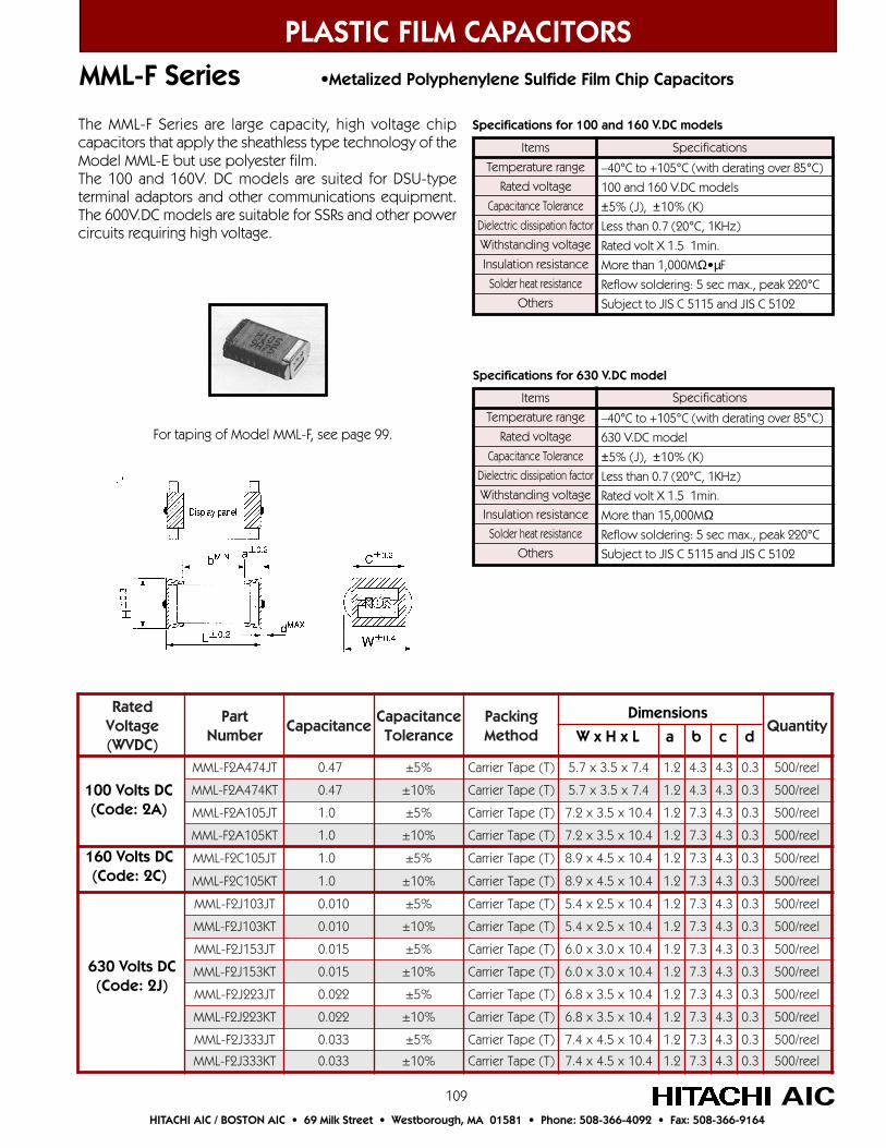
109
PLASTIC FILM CAPACITORSMML-F Series •Metalized Polyphenylene Sulfide Film Chip Capacitors
AICHITACHI AIC / BOSTON AIC • 69 Milk Street • Westborough, MA 01581 • Phone: 508-366-4092 • Fax: 508-366-9164
detaRegatloV)CDVW(
traPrebmuN
ecnaticapaCecnaticapaC
ecnareloTgnikcaPdohteM
ytitnauQ
TJ474A2F-LMM 74.0 %5± )T(epaTreirraC 4.7x5.3x7.5 2.1 3.4 3.4 3.0 leer/005
TK474A2F-LMM 74.0 %01± )T(epaTreirraC 4.7x5.3x7.5 2.1 3.4 3.4 3.0 leer/005
TJ501A2F-LMM 0.1 %5± )T(epaTreirraC 4.01x5.3x2.7 2.1 3.7 3.4 3.0 leer/005
TK501A2F-LMM 0.1 %01± )T(epaTreirraC 4.01x5.3x2.7 2.1 3.7 3.4 3.0 leer/005
TJ501C2F-LMM 0.1 %5± )T(epaTreirraC 4.01x5.4x9.8 2.1 3.7 3.4 3.0 leer/005
TK501C2F-LMM 0.1 %01± )T(epaTreirraC 4.01x5.4x9.8 2.1 3.7 3.4 3.0 leer/005
TJ301J2F-LMM 010.0 %5± )T(epaTreirraC 4.01x5.2x4.5 2.1 3.7 3.4 3.0 leer/005
TK301J2F-LMM 010.0 %01± )T(epaTreirraC 4.01x5.2x4.5 2.1 3.7 3.4 3.0 leer/005
TJ351J2F-LMM 510.0 %5± )T(epaTreirraC 4.01x0.3x0.6 2.1 3.7 3.4 3.0 leer/005
TK351J2F-LMM 510.0 %01± )T(epaTreirraC 4.01x0.3x0.6 2.1 3.7 3.4 3.0 leer/005
TJ322J2F-LMM 220.0 %5± )T(epaTreirraC 4.01x5.3x8.6 2.1 3.7 3.4 3.0 leer/005
TK322J2F-LMM 220.0 %01± )T(epaTreirraC 4.01x5.3x8.6 2.1 3.7 3.4 3.0 leer/005
TJ333J2F-LMM 330.0 %5± )T(epaTreirraC 4.01x5.4x4.7 2.1 3.7 3.4 3.0 leer/005
TK333J2F-LMM 330.0 %01± )T(epaTreirraC 4.01x5.4x4.7 2.1 3.7 3.4 3.0 leer/005
Dimensions
W x H x L a b c d
Items
Temperature range
Rated voltage
Capacitance Tolerance
Dielectric dissipation factor
Withstanding voltage
Insulation resistance
Solder heat resistance
Others
–40°C to +105°C (with derating over 85°C)
100 and 160 V.DC models
±5% (J), ±10% (K)
Less than 0.7 (20°C, 1KHz)
Rated volt X 1.5 1min.
More than 1,000MΩ•µF
Reflow soldering: 5 sec max., peak 220°C
Subject to JIS C 5115 and JIS C 5102
Specifications
Items
Temperature range
Rated voltage
Capacitance Tolerance
Dielectric dissipation factor
Withstanding voltage
Insulation resistance
Solder heat resistance
Others
–40°C to +105°C (with derating over 85°C)
630 V.DC model
±5% (J), ±10% (K)
Less than 0.7 (20°C, 1KHz)
Rated volt X 1.5 1min.
More than 15,000MΩReflow soldering: 5 sec max., peak 220°C
Subject to JIS C 5115 and JIS C 5102
Specifications
Specifications for 100 and 160 V.DC models
Specifications for 630 V.DC model
The MML-F Series are large capacity, high voltage chipcapacitors that apply the sheathless type technology of theModel MML-E but use polyester film.The 100 and 160V. DC models are suited for DSU-typeterminal adaptors and other communications equipment.The 600V.DC models are suitable for SSRs and other powercircuits requiring high voltage.
For taping of Model MML-F, see page 99.
100 Volts DC(Code: 2A)
630 Volts DC(Code: 2J)
160 Volts DC(Code: 2C)
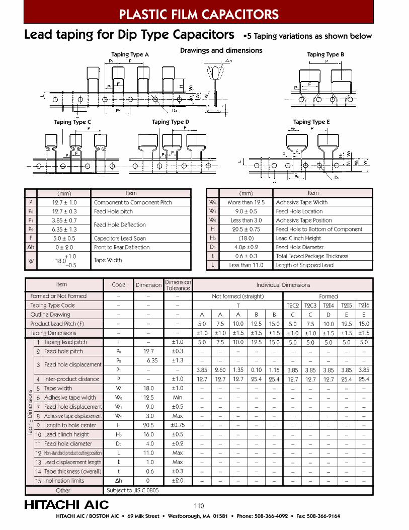
110
PLASTIC FILM CAPACITORSLead taping for Dip Type Capacitors •5 Taping variations as shown below
AICHITACHI AIC / BOSTON AIC • 69 Milk Street • Westborough, MA 01581 • Phone: 508-366-4092 • Fax: 508-366-9164
Drawings and dimensions
(mm)
More than 12.5
9.0 ± 0.5
Less than 3.0
20.5 ± 0.75
(18.0)
4.0ø ±0.2
0.6 ± 0.3
Less than 11.0
Adhesive Tape Width
Feed Hole Location
Adhesive Tape Position
Feed Hole to Bottom of Component
Lead Clinch Height
Feed Hole Diameter
Total Taped Package Thickness
Length of Snipped Lead
Item
Individual DimensionsDimensionTolerance
Code DimensionItem
Formed or Not Formed
Taping Type Code
Outline Drawing
Product Lead Pitch (F)
Taping Dimensions
–
–
–
–
–
F
P0
P2
P1
P
W
W0
W1
W2
H
H0
D0
L
l
t
∆h
–
–
–
–
–
–
12.7
6.35
–
–
18.0
12.5
9.0
3.0
20.5
16.0
4.0
11.0
1.0
0.6
0
–
–
–
–
–
±1.0
±0.3
±1.3
–
±1.0
±1.0
Min
±0.5
Max
±0.75
±0.5
±0.2
Max
Max
±0.3
±2.0
Subject to JIS C 0805Other
1
2
4
5
6
7
8
9
10
11
12
13
14
15
3
Taping lead pitch
Feed hole pitch
Inter-product distance
Tape width
Adhesive tape width
Feed hole displacement
Adhesive tape displacement
Length to hole center
Lead clinch height
Feed hole diameter
Non-standard product cutting position
Lead displacement length
Tape thickness (overall)
Inolination limits
Feed hole displacement
Tap
ing
Dim
ensi
ons
Not formed (straight) Formed
T
A
5.0
±1.0
5.0
–
–
3.85
12.7
–
–
–
–
–
–
–
–
–
–
–
B
15.0
±1.5
15.0
–
–
1.15
25.4
–
–
–
–
–
–
–
–
–
–
–
B
12.5
±1.5
12.5
–
–
0.10
25.4
–
–
–
–
–
–
–
–
–
–
–
A
10.0
±1.5
10.0
–
–
1.35
12.7
–
–
–
–
–
–
–
–
–
–
–
A
7.5
±1.0
7.5
–
–
2.60
12.7
–
–
–
–
–
–
–
–
–
–
–
T2C2
C
5.0
±1.0
5.0
–
–
3.85
12.7
–
–
–
–
–
–
–
–
–
–
–
T2I6E
15.0
±1.5
5.0
–
–
3.85
25.4
–
–
–
–
–
–
–
–
–
–
–
T2C3
C
7.5
±1.0
5.0
–
–
3.85
12.7
–
–
–
–
–
–
–
–
–
–
–
T2I4D
10.0
±1.5
5.0
–
–
3.85
12.7
–
–
–
–
–
–
–
–
–
–
–
T2I5E
12.5
±1.5
5.0
–
–
3.85
25.4
–
–
–
–
–
–
–
–
–
–
–
Taping Type A Taping Type B
Taping Type C Taping Type D Taping Type E
W0
W1
W2
H
H0
D0
t
L
(mm)
12.7 ± 1.0
12.7 ± 0.3
3.85 ± 0.7
6.35 ± 1.3
5.0 ± 0.5
0 ± 2.0
+1.0
–0.5
Component to Component Pitch
Feed Hole pitch
Capacitors Lead Span
Front to Rear Deflection
Item
P
P0
P1
P2
F
∆h
18.0
Feed Hole Deflection
Tape WidthW
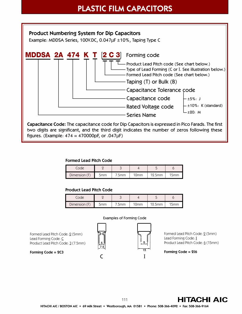
111
PLASTIC FILM CAPACITORS
AICHITACHI AIC / BOSTON AIC • 69 Milk Street • Westborough, MA 01581 • Phone: 508-366-4092 • Fax: 508-366-9164
Product Numbering System for Dip CapacitorsExample: MDDSA Series, 100V.DC, 0.047µF ±10%, Taping Type C
Taping (T) or Bulk (B)
Capacitance Tolerance code
Capacitance code
Rated Voltage code
Series Name
MDDSA 2A 474 K T [2 C 3]
±5%: J
±10%: K (standard)
±20: M
Forming code
Product Lead Pitch code (See chart below.)Type of Lead Forming (C or I. See illustration below.)Formed Lead Pitch code (See chart below.)
Code 2 3 4 5 6
Dimension (F) 5mm 7.5mm 10mm 12.5mm 15mm
Product Lead Pitch Code
Code 2 3 4 5 6
Dimension (F) 5mm 7.5mm 10mm 12.5mm 15mm
Formed Lead Pitch Code
Examples of Forming Code
Formed Lead Pitch Code: 2 (5mm)Lead Forming Code: CProduct Lead Pitch Code: 3 (7.5mm)
Forming Code = 2C3
Formed Lead Pitch Code: 2 (5mm)Lead Forming Code: IProduct Lead Pitch Code: 6 (15mm)
Forming Code = 2I6IC
Capacitance Code: The capacitance code for Dip Capacitors is expressed in Pico Farads. The firsttwo digits are significant, and the third digit indicates the number of zeros following thesefigures. (Example: 474 = 470000pF, or .047µF)
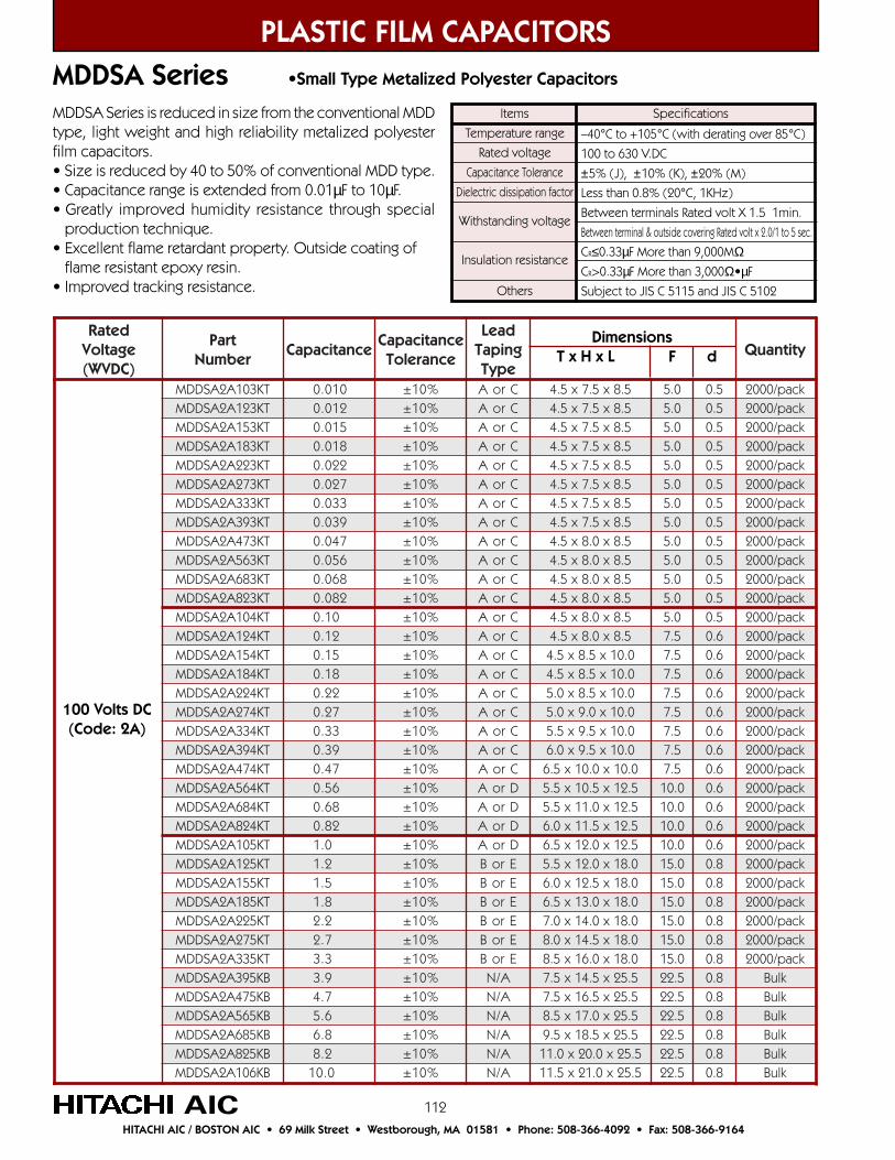
112
detaRegatloV)CDVW(
traPrebmuN
ecnaticapaCecnaticapaC
ecnareloT
daeLgnipaT
epyTytitnauQ
TK301A2ASDDM 010.0 %01± CroA 5.8x5.7x5.4 0.5 5.0 kcap/0002TK321A2ASDDM 210.0 %01± CroA 5.8x5.7x5.4 0.5 5.0 kcap/0002TK351A2ASDDM 510.0 %01± CroA 5.8x5.7x5.4 0.5 5.0 kcap/0002TK381A2ASDDM 810.0 %01± CroA 5.8x5.7x5.4 0.5 5.0 kcap/0002TK322A2ASDDM 220.0 %01± CroA 5.8x5.7x5.4 0.5 5.0 kcap/0002TK372A2ASDDM 720.0 %01± CroA 5.8x5.7x5.4 0.5 5.0 kcap/0002TK333A2ASDDM 330.0 %01± CroA 5.8x5.7x5.4 0.5 5.0 kcap/0002TK393A2ASDDM 930.0 %01± CroA 5.8x5.7x5.4 0.5 5.0 kcap/0002TK374A2ASDDM 740.0 %01± CroA 5.8x0.8x5.4 0.5 5.0 kcap/0002TK365A2ASDDM 650.0 %01± CroA 5.8x0.8x5.4 0.5 5.0 kcap/0002TK386A2ASDDM 860.0 %01± CroA 5.8x0.8x5.4 0.5 5.0 kcap/0002TK328A2ASDDM 280.0 %01± CroA 5.8x0.8x5.4 0.5 5.0 kcap/0002TK401A2ASDDM 01.0 %01± CroA 5.8x0.8x5.4 0.5 5.0 kcap/0002TK421A2ASDDM 21.0 %01± CroA 5.8x0.8x5.4 5.7 6.0 kcap/0002TK451A2ASDDM 51.0 %01± CroA 0.01x5.8x5.4 5.7 6.0 kcap/0002TK481A2ASDDM 81.0 %01± CroA 0.01x5.8x5.4 5.7 6.0 kcap/0002TK422A2ASDDM 22.0 %01± CroA 0.01x5.8x0.5 5.7 6.0 kcap/0002TK472A2ASDDM 72.0 %01± CroA 0.01x0.9x0.5 5.7 6.0 kcap/0002TK433A2ASDDM 33.0 %01± CroA 0.01x5.9x5.5 5.7 6.0 kcap/0002TK493A2ASDDM 93.0 %01± CroA 0.01x5.9x0.6 5.7 6.0 kcap/0002TK474A2ASDDM 74.0 %01± CroA 0.01x0.01x5.6 5.7 6.0 kcap/0002TK465A2ASDDM 65.0 %01± DroA 5.21x5.01x5.5 0.01 6.0 kcap/0002TK486A2ASDDM 86.0 %01± DroA 5.21x0.11x5.5 0.01 6.0 kcap/0002TK428A2ASDDM 28.0 %01± DroA 5.21x5.11x0.6 0.01 6.0 kcap/0002TK501A2ASDDM 0.1 %01± DroA 5.21x0.21x5.6 0.01 6.0 kcap/0002TK521A2ASDDM 2.1 %01± EroB 0.81x0.21x5.5 0.51 8.0 kcap/0002TK551A2ASDDM 5.1 %01± EroB 0.81x5.21x0.6 0.51 8.0 kcap/0002TK581A2ASDDM 8.1 %01± EroB 0.81x0.31x5.6 0.51 8.0 kcap/0002TK522A2ASDDM 2.2 %01± EroB 0.81x0.41x0.7 0.51 8.0 kcap/0002TK572A2ASDDM 7.2 %01± EroB 0.81x5.41x0.8 0.51 8.0 kcap/0002TK533A2ASDDM 3.3 %01± EroB 0.81x0.61x5.8 0.51 8.0 kcap/0002BK593A2ASDDM 9.3 %01± A/N 5.52x5.41x5.7 5.22 8.0 kluBBK574A2ASDDM 7.4 %01± A/N 5.52x5.61x5.7 5.22 8.0 kluBBK565A2ASDDM 6.5 %01± A/N 5.52x0.71x5.8 5.22 8.0 kluBBK586A2ASDDM 8.6 %01± A/N 5.52x5.81x5.9 5.22 8.0 kluBBK528A2ASDDM 2.8 %01± A/N 5.52x0.02x0.11 5.22 8.0 kluBBK601A2ASDDM 0.01 %01± A/N 5.52x0.12x5.11 5.22 8.0 kluB
PLASTIC FILM CAPACITORS
AICHITACHI AIC / BOSTON AIC • 69 Milk Street • Westborough, MA 01581 • Phone: 508-366-4092 • Fax: 508-366-9164
MDDSA Series •Small Type Metalized Polyester Capacitors
Items
Temperature range
Rated voltage
Capacitance Tolerance
Dielectric dissipation factor
Withstanding voltage
Insulation resistance
Others
–40°C to +105°C (with derating over 85°C)
100 to 630 V.DC
±5% (J), ±10% (K), ±20% (M)
Less than 0.8% (20°C, 1KHz)
Between terminals Rated volt X 1.5 1min.
Between terminal & outside covering Rated volt x 2.0/1 to 5 sec.
CR≤0.33µF More than 9,000MΩCR>0.33µF More than 3,000Ω•µF
Subject to JIS C 5115 and JIS C 5102
SpecificationsMDDSA Series is reduced in size from the conventional MDDtype, light weight and high reliability metalized polyesterfilm capacitors.• Size is reduced by 40 to 50% of conventional MDD type.• Capacitance range is extended from 0.01µF to 10µF.• Greatly improved humidity resistance through special production technique.• Excellent flame retardant property. Outside coating of flame resistant epoxy resin.• Improved tracking resistance.
100 Volts DC(Code: 2A)
Dimensions T x H x L F d

113
PLASTIC FILM CAPACITORS
AICHITACHI AIC / BOSTON AIC • 69 Milk Street • Westborough, MA 01581 • Phone: 508-366-4092 • Fax: 508-366-9164
MDDSA Series •Small Type Metalized Polyester Capacitors
detaRegatloV)CDVW(
traPrebmuN
ecnaticapaCecnaticapaC
ecnareloT
daeLgnipaT
epyTytitnauQ
TK301E2ASDDM 010.0 %01± CroA 0.01x0.8x5.4 5.7 6.0 kcap/0002TK321E2ASDDM 210.0 %01± CroA 0.01x5.8x5.4 5.7 6.0 kcap/0002TK351E2ASDDM 510.0 %01± CroA 0.01x0.8x5.4 5.7 6.0 kcap/0002TK381E2ASDDM 810.0 %01± CroA 0.01x0.8x5.4 5.7 6.0 kcap/0002TK322E2ASDDM 220.0 %01± CroA 0.01x0.8x5.4 5.7 6.0 kcap/0002TK372E2ASDDM 720.0 %01± CroA 0.01x0.8x5.4 5.7 6.0 kcap/0002TK333E2ASDDM 330.0 %01± CroA 0.01x0.8x5.4 5.7 6.0 kcap/0002TK393E2ASDDM 930.0 %01± CroA 0.01x0.8x5.4 5.7 6.0 kcap/0002TK374E2ASDDM 740.0 %01± CroA 0.01x0.8x5.4 5.7 6.0 kcap/0002TK365E2ASDDM 650.0 %01± CroA 0.01x0.8x5.4 5.7 6.0 kcap/0002TK386E2ASDDM 860.0 %01± CroA 0.01x5.8x5.4 5.7 6.0 kcap/0002TK328E2ASDDM 280.0 %01± CroA 0.01x0.9x5.4 5.7 6.0 kcap/0002TK401E2ASDDM 01.0 %01± CroA 0.01x0.9x0.5 5.7 6.0 kcap/0051TK421E2ASDDM 21.0 %01± CroA 0.01x5.9x5.5 5.7 6.0 kcap/0051TK451E2ASDDM 51.0 %01± CroA 0.01x0.01x0.6 5.7 6.0 kcap/0001TK481E2ASDDM 81.0 %01± DroA 5.21x0.01x0.5 0.01 6.0 kcap/0051TK422E2ASDDM 22.0 %01± DroA 5.21x5.01x5.5 0.01 6.0 kcap/0051TK472E2ASDDM 72.0 %01± DroA 5.21x0.11x0.6 0.01 6.0 kcap/0001TK433E2ASDDM 33.0 %01± DroA 5.21x5.11x5.6 0.01 6.0 kcap/0001TK493E2ASDDM 93.0 %01± EroB 0.81x0.21x0.5 0.51 6.0 kcap/005TK474E2ASDDM 74.0 %01± EroB 0.81x0.21x5.5 0.51 6.0 kcap/005TK465E2ASDDM 65.0 %01± EroB 0.81x5.21x0.6 0.51 6.0 kcap/005TK486E2ASDDM 86.0 %01± EroB 0.81x0.31x5.6 0.51 8.0 kcap/005TK428E2ASDDM 28.0 %01± EroB 0.81x0.31x0.7 0.51 8.0 kcap/005TK501E2ASDDM 0.1 %01± EroB 0.81x5.41x5.7 0.51 8.0 kcap/005TK521E2ASDDM 2.1 %01± EroB 0.81x0.51x5.8 5.22 8.0 kcap/005BK551E2ASDDM 5.1 %01± A/N 0.81x0.61x0.9 5.22 8.0 kluBBK581E2ASDDM 8.1 %01± A/N 5.52x0.51x0.8 5.22 8.0 kluBBK522E2ASDDM 2.2 %01± A/N 5.52x0.61x0.9 5.22 8.0 kluBBK572E2ASDDM 7.2 %01± A/N 5.52x0.71x0.01 5.22 8.0 kluBBK533E2ASDDM 3.3 %01± A/N 5.52x0.81x0.11 5.22 8.0 kluBBK593E2ASDDM 9.3 %01± A/N 5.52x0.02x5.11 5.22 8.0 kluBBK574E2ASDDM 7.4 %01± A/N 5.52x0.12x5.21 5.22 8.0 kluBBK565E2ASDDM 6.5 %01± A/N 5.03x0.12x0.21 5.72 8.0 kluBBK586E2ASDDM 8.6 %01± A/N 5.03x0.22x0.41 5.72 8.0 kluBBK528E2ASDDM 2.8 %01± A/N 5.03x0.32x0.51 5.72 8.0 kluBBK601E2ASDDM 0.01 %01± A/N 5.03x0.52x5.61 5.72 8.0 kluB
250 Volts DC(Code: 2E)
G: 1.0 mm when F Dimension is less than 7.5 mm. 1.5 mm when F Dimension is less than 10 mm.
Dimensions T x H x L F d

114
detaRegatloV)CDVW(
traPrebmuN
ecnaticapaCecnaticapaC
ecnareloT
daeLgnipaT
epyTytitnauQ
TK301G2ASDDM 010.0 %01± CroA 0.01x0.8x5.4 5.7 6.0 kcap/0002
TK321G2ASDDM 210.0 %01± CroA 0.01x5.8x5.4 5.7 6.0 kcap/0002
TK351G2ASDDM 510.0 %01± CroA 0.01x0.8x5.4 5.7 6.0 kcap/0002
TK381G2ASDDM 810.0 %01± CroA 0.01x0.8x5.4 5.7 6.0 kcap/0002
TK322G2ASDDM 220.0 %01± CroA 0.01x0.8x5.4 5.7 6.0 kcap/0002
TK372G2ASDDM 720.0 %01± CroA 0.01x5.8x0.5 5.7 6.0 kcap/0002
TK333G2ASDDM 330.0 %01± CroA 0.01x0.9x0.5 5.7 6.0 kcap/0051
TK393G2ASDDM 930.0 %01± DroA 5.21x0.8x5.4 0.01 6.0 kcap/0002
TK374G2ASDDM 740.0 %01± DroA 5.21x0.9x5.4 0.01 6.0 kcap/0002
TK365G2ASDDM 650.0 %01± DroA 5.21x0.9x0.5 0.01 6.0 kcap/0051
TK386G2ASDDM 860.0 %01± DroA 5.21x5.9x5.5 0.01 6.0 kcap/0051
TK328G2ASDDM 280.0 %01± DroA 5.21x5..01x5.5 0.01 6.0 kcap/0051
TK401G2ASDDM 01.0 %01± DroA 5.21x0.11x0.6 0.01 6.0 kcap/0051
TK421G2ASDDM 21.0 %01± EroB 0.81x0.01x0.5 0.51 6.0 kcap/005
TK451G2ASDDM 51.0 %01± EroB 0.81x5.01x0.5 0.51 6.0 kcap/005
TK481G2ASDDM 81.0 %01± EroB 0.81x0.11x5.5 0.51 6.0 kcap/005
TK422G2ASDDM 22.0 %01± EroB 0.81x0.21x0.6 0.51 6.0 kcap/005
TK472G2ASDDM 72.0 %01± EroB 0.81x5.21x5.6 0.51 8.0 kcap/005
TK433G2ASDDM 33.0 %01± EroB 0.81x5.21x0.7 0.51 8.0 kcap/005
TK493G2ASDDM 93.0 %01± EroB 0.81x0.41x0.7 0.51 8.0 kcap/005
TK474G2ASDDM 74.0 %01± EroB 0.81x5.41x0.8 0.51 8.0 kcap/005
BK465G2ASDDM 65.0 %01± A/N 5.52x0.41x0.7 5.22 8.0 kluB
BK486G2ASDDM 86.0 %01± A/N 5.52x5.41x5.7 5.22 8.0 kluB
BK428G2ASDDM 28.0 %01± A/N 5.52x0.61x5.7 5.22 8.0 kluB
BK501G2ASDDM 0.1 %01± A/N 5.52x0.71x5.8 5.22 8.0 kluB
BK521G2ASDDM 2.1 %01± A/N 5.52x0.81x5.9 5.22 8.0 kluB
BK551G2ASDDM 5.1 %01± A/N 5.03x0.81x0.9 5.72 8.0 kluB
BK581G2ASDDM 8.1 %01± A/N 5.03x0.91x0.01 5.72 8.0 kluB
BK522G2ASDDM 2.2 %01± A/N 5.03x0.02x0.11 5.72 8.0 kluB
PLASTIC FILM CAPACITORS
AICHITACHI AIC / BOSTON AIC • 69 Milk Street • Westborough, MA 01581 • Phone: 508-366-4092 • Fax: 508-366-9164
MDDSA Series •Small Type Metalized Polyester Capacitors
400 Volts DC(Code: 2G)
Dimensions T x H x L F d
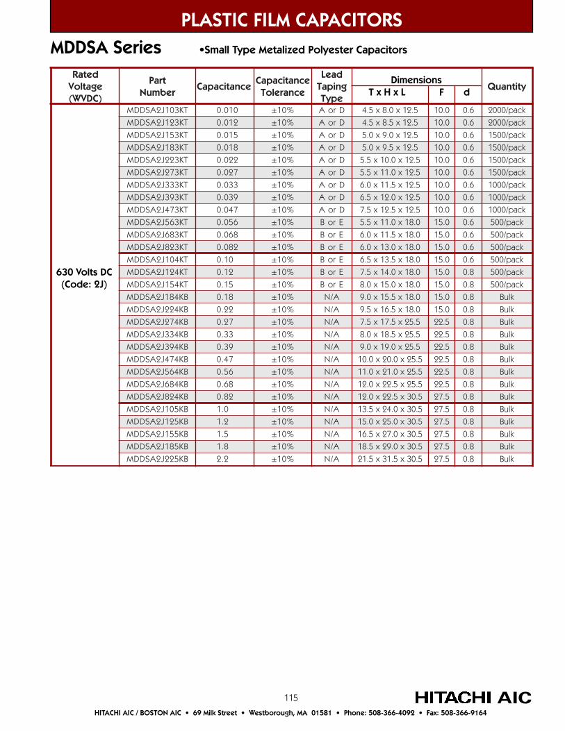
115
PLASTIC FILM CAPACITORS
AICHITACHI AIC / BOSTON AIC • 69 Milk Street • Westborough, MA 01581 • Phone: 508-366-4092 • Fax: 508-366-9164
MDDSA Series •Small Type Metalized Polyester Capacitors
detaRegatloV)CDVW(
traPrebmuN
ecnaticapaCecnaticapaC
ecnareloT
daeLgnipaT
epyTytitnauQ
TK301J2ASDDM 010.0 %01± DroA 5.21x0.8x5.4 0.01 6.0 kcap/0002
TK321J2ASDDM 210.0 %01± DroA 5.21x5.8x5.4 0.01 6.0 kcap/0002
TK351J2ASDDM 510.0 %01± DroA 5.21x0.9x0.5 0.01 6.0 kcap/0051
TK381J2ASDDM 810.0 %01± DroA 5.21x5.9x0.5 0.01 6.0 kcap/0051
TK322J2ASDDM 220.0 %01± DroA 5.21x0.01x5.5 0.01 6.0 kcap/0051
TK372J2ASDDM 720.0 %01± DroA 5.21x0.11x5.5 0.01 6.0 kcap/0051
TK333J2ASDDM 330.0 %01± DroA 5.21x5.11x0.6 0.01 6.0 kcap/0001
TK393J2ASDDM 930.0 %01± DroA 5.21x0.21x5.6 0.01 6.0 kcap/0001
TK374J2ASDDM 740.0 %01± DroA 5.21x5.21x5.7 0.01 6.0 kcap/0001
TK365J2ASDDM 650.0 %01± EroB 0.81x0.11x5.5 0.51 6.0 kcap/005
TK386J2ASDDM 860.0 %01± EroB 0.81x5.11x0.6 0.51 6.0 kcap/005
TK328J2ASDDM 280.0 %01± EroB 0.81x0.31x0.6 0.51 6.0 kcap/005
TK401J2ASDDM 01.0 %01± EroB 0.81x5.31x5.6 0.51 6.0 kcap/005
TK421J2ASDDM 21.0 %01± EroB 0.81x0.41x5.7 0.51 8.0 kcap/005
TK451J2ASDDM 51.0 %01± EroB 0.81x0.51x0.8 0.51 8.0 kcap/005
BK481J2ASDDM 81.0 %01± A/N 0.81x5.51x0.9 0.51 8.0 kluB
BK422J2ASDDM 22.0 %01± A/N 0.81x5.61x5.9 0.51 8.0 kluB
BK472J2ASDDM 72.0 %01± A/N 5.52x5.71x5.7 5.22 8.0 kluB
BK433J2ASDDM 33.0 %01± A/N 5.52x5.81x0.8 5.22 8.0 kluB
BK493J2ASDDM 93.0 %01± A/N 5.52x0.91x0.9 5.22 8.0 kluB
BK474J2ASDDM 74.0 %01± A/N 5.52x0.02x0.01 5.22 8.0 kluB
BK465J2ASDDM 65.0 %01± A/N 5.52x0.12x0.11 5.22 8.0 kluB
BK486J2ASDDM 86.0 %01± A/N 5.52x5.22x0.21 5.22 8.0 kluB
BK428J2ASDDM 28.0 %01± A/N 5.03x5.22x0.21 5.72 8.0 kluB
BK501J2ASDDM 0.1 %01± A/N 5.03x0.42x5.31 5.72 8.0 kluB
BK521J2ASDDM 2.1 %01± A/N 5.03x0.52x0.51 5.72 8.0 kluB
BK551J2ASDDM 5.1 %01± A/N 5.03x0.72x5.61 5.72 8.0 kluB
BK581J2ASDDM 8.1 %01± A/N 5.03x0.92x5.81 5.72 8.0 kluB
BK522J2ASDDM 2.2 %01± A/N 5.03x5.13x5.12 5.72 8.0 kluB
630 Volts DC(Code: 2J)
Dimensions T x H x L F d
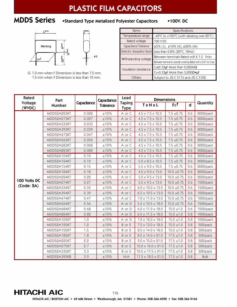
116
detaRegatloV)CDVW(
traPrebmuN
ecnaticapaCecnaticapaC
ecnareloT
daeLgnipaT
epyTytitnauQ
TK322A2SDDM 220.0 %01± CroA 5.01x5.7x5.4 57.0±5.7 6.0 kcap/0002
TK372A2SDDM 720.0 %01± CroA 5.01x5.7x5.4 57.0±5.7 6.0 kcap/0002
TK333A2SDDM 330.0 %01± CroA 5.01x5.7x5.4 57.0±5.7 6.0 kcap/0002
TK393A2SDDM 930.0 %01± CroA 5.01x5.7x5.4 57.0±5.7 6.0 kcap/0002
TK374A2SDDM 740.0 %01± CroA 5.01x5.7x5.4 57.0±5.7 6.0 kcap/0002
TK365A2SDDM 650.0 %01± CroA 5.01x5.7x5.4 57.0±5.7 6.0 kcap/0002
TK386A2SDDM 860.0 %01± CroA 5.01x5.7x5.4 57.0±5.7 6.0 kcap/0002
TK328A2SDDM 280.0 %01± CroA 5.01x5.7x5.4 57.0±5.7 6.0 kcap/0002
TK401A2SDDM 01.0 %01± CroA 5.01x5.7x5.4 57.0±5.7 6.0 kcap/0002
TK421A2SDDM 21.0 %01± CroA 5.01x5.8x0.5 57.0±5.7 6.0 kcap/0002
TK451A2SDDM 51.0 %01± CroA 5.01x0.9x5.5 57.0±5.7 6.0 kcap/0002
TK481A2SDDM 81.0 %01± CroA 0.31x0.9x5.4 57.0±0.01 6.0 kcap/0002
TK422A2SDDM 22.0 %01± CroA 0.31x5.9x0.5 57.0±0.01 6.0 kcap/0002
TK472A2SDDM 72.0 %01± CroA 0.31x5.9x5.5 57.0±0.01 6.0 kcap/0051
TK433A2SDDM 33.0 %01± CroA 0.31x0.01x0.6 57.0±0.01 6.0 kcap/0051
TK493A2SDDM 93.0 %01± CroA 0.31x5.01x5.6 57.0±0.01 6.0 kcap/0001
TK474A2SDDM 74.0 %01± CroA 0.31x0.11x0.7 57.0±0.51 6.0 kcap/0001
TK465A2SDDM 65.0 %01± DroA 0.81x5.01x5.5 57.0±0.51 6.0 kcap/0051
TK486A2SDDM 86.0 %01± DroA 0.81x0.11x0.6 0.1±0.51 6.0 kcap/0051
TK428A2SDDM 28.0 %01± DroA 0.81x5.11x5.6 0.1±0.51 8.0 kcap/0001
TK501A2SDDM 0.1 %01± DroA 0.81x0.21x0.7 0.1±0.51 8.0 kcap/0001
TK521A2SDDM 2.1 %01± EroB 0.81x0.31x5.7 0.1±0.51 8.0 kcap/005
TK551A2SDDM 5.1 %01± EroB 0.81x0.41x5.8 0.1±0.51 8.0 kcap/005
TK581A2SDDM 8.1 %01± EroB 0.12x0.41x5.8 0.1±5.71 8.0 kcap/005
TK522A2SDDM 2.2 %01± EroB 0.12x0.51x0.9 0.1±5.71 8.0 kcap/005
TK572A2SDDM 7.2 %01± EroB 0.12x0.61x0.01 0.1±5.71 8.0 kcap/005
TK533A2SDDM 3.3 %01± EroB 0.12x5.71x5.01 0.1±5.71 8.0 kcap/005
BK593A2SDDM 9.3 %01± A/N 0.12x5.81x5.11 0.1±5.71 8.0 kluB
PLASTIC FILM CAPACITORS
AICHITACHI AIC / BOSTON AIC • 69 Milk Street • Westborough, MA 01581 • Phone: 508-366-4092 • Fax: 508-366-9164
MDDS Series •Standard Type Metalized Polyester Capacitors •100V. DC
100 Volts DC(Code: 2A)
Items
Temperature range
Rated voltage
Capacitance Tolerance
Dielectric dissipation factor
Withstanding voltage
Insulation resistance
Others
–40°C to +105°C (with derating over 85°C)
100 V.DC
±5% (J), ±10% (K), ±20% (M)
Less than 0.8% (20°C, 1KHz)
Between terminals Rated volt X 1.5 1min.
Between terminal & outside covering Rated volt x 2.0/1 to 5 sec.
CR≤0.33µF More than 9,000MΩCR>0.33µF More than 3,000Ω•µF
Subject to JIS C 5115 and JIS C 5102
Specifications
G: 1.0 mm when F Dimension is less than 7.5 mm. 1.5 mm when F Dimension is less than 10 mm.
Dimensions T x H x L F±f d
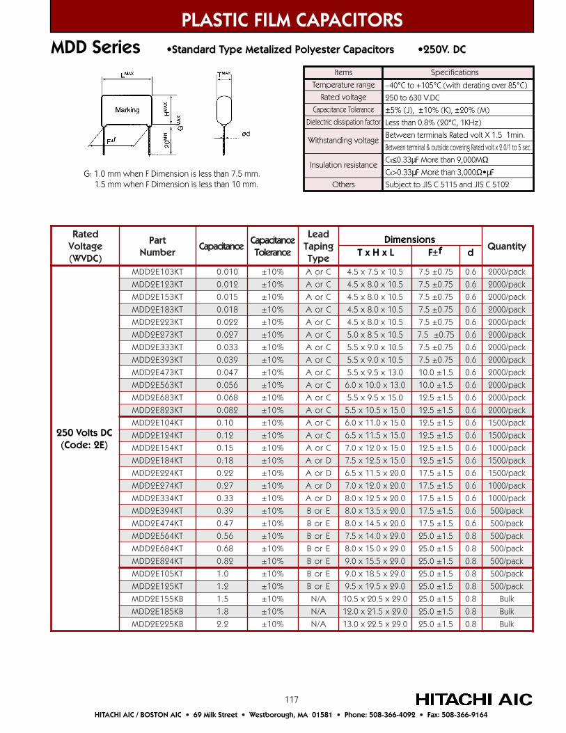
117
detaRegatloV)CDVW(
traPrebmuN
ecnaticapaCecnaticapaC
ecnareloT
daeLgnipaT
epyTytitnauQ
TK301E2DDM 010.0 %01± CroA 5.01x5.7x5.4 57.0±5.7 6.0 kcap/0002
TK321E2DDM 210.0 %01± CroA 5.01x0.8x5.4 57.0±5.7 6.0 kcap/0002
TK351E2DDM 510.0 %01± CroA 5.01x0.8x5.4 57.0±5.7 6.0 kcap/0002
TK381E2DDM 810.0 %01± CroA 5.01x0.8x5.4 57.0±5.7 6.0 kcap/0002
TK322E2DDM 220.0 %01± CroA 5.01x0.8x5.4 57.0±5.7 6.0 kcap/0002
TK372E2DDM 720.0 %01± CroA 5.01x5.8x0.5 57.0±5.7 6.0 kcap/0002
TK333E2DDM 330.0 %01± CroA 5.01x0.9x5.5 57.0±5.7 6.0 kcap/0002
TK393E2DDM 930.0 %01± CroA 5.01x0.9x5.5 57.0±5.7 6.0 kcap/0002
TK374E2DDM 740.0 %01± CroA 0.31x5.9x5.5 5.1±0.01 6.0 kcap/0002
TK365E2DDM 650.0 %01± CroA 0.31x0.01x0.6 5.1±0.01 6.0 kcap/0002
TK386E2DDM 860.0 %01± CroA 0.51x5.9x5.5 5.1±5.21 6.0 kcap/0002
TK328E2DDM 280.0 %01± CroA 0.51x5.01x5.5 5.1±5.21 6.0 kcap/0002
TK401E2DDM 01.0 %01± CroA 0.51x0.11x0.6 5.1±5.21 6.0 kcap/0051
TK421E2DDM 21.0 %01± CroA 0.51x5.11x5.6 5.1±5.21 6.0 kcap/0051
TK451E2DDM 51.0 %01± CroA 0.51x0.21x0.7 5.1±5.21 6.0 kcap/0001
TK481E2DDM 81.0 %01± DroA 0.51x5.21x5.7 5.1±5.21 6.0 kcap/0051
TK422E2DDM 22.0 %01± DroA 0.02x5.11x5.6 5.1±5.71 6.0 kcap/0051
TK472E2DDM 72.0 %01± DroA 0.02x0.21x0.7 5.1±5.71 6.0 kcap/0001
TK433E2DDM 33.0 %01± DroA 0.02x5.21x0.8 5.1±5.71 6.0 kcap/0001
TK493E2DDM 93.0 %01± EroB 0.02x5.31x0.8 5.1±5.71 6.0 kcap/005
TK474E2DDM 74.0 %01± EroB 0.02x5.41x0.8 5.1±5.71 6.0 kcap/005
TK465E2DDM 65.0 %01± EroB 0.92x0.41x5.7 5.1±0.52 8.0 kcap/005
TK486E2DDM 86.0 %01± EroB 0.92x0.51x0.8 5.1±0.52 8.0 kcap/005
TK428E2DDM 28.0 %01± EroB 0.92x5.51x0.9 5.1±0.52 8.0 kcap/005
TK501E2DDM 0.1 %01± EroB 0.92x5.81x0.9 5.1±0.52 8.0 kcap/005
TK521E2DDM 2.1 %01± EroB 0.92x5.91x5.9 5.1±0.52 8.0 kcap/005
BK551E2DDM 5.1 %01± A/N 0.92x5.02x5.01 5.1±0.52 8.0 kluB
BK581E2DDM 8.1 %01± A/N 0.92x5.12x0.21 5.1±0.52 8.0 kluB
BK522E2DDM 2.2 %01± A/N 0.92x5.22x0.31 5.1±0.52 8.0 kluB
PLASTIC FILM CAPACITORS
AICHITACHI AIC / BOSTON AIC • 69 Milk Street • Westborough, MA 01581 • Phone: 508-366-4092 • Fax: 508-366-9164
MDD Series •Standard Type Metalized Polyester Capacitors •250V. DC
Items
Temperature range
Rated voltage
Capacitance Tolerance
Dielectric dissipation factor
Withstanding voltage
Insulation resistance
Others
–40°C to +105°C (with derating over 85°C)
250 to 630 V.DC
±5% (J), ±10% (K), ±20% (M)
Less than 0.8% (20°C, 1KHz)
Between terminals Rated volt X 1.5 1min.
Between terminal & outside covering Rated volt x 2.0/1 to 5 sec.
CR≤0.33µF More than 9,000MΩCR>0.33µF More than 3,000Ω•µF
Subject to JIS C 5115 and JIS C 5102
Specifications
G: 1.0 mm when F Dimension is less than 7.5 mm. 1.5 mm when F Dimension is less than 10 mm.
250 Volts DC(Code: 2E)
Dimensions T x H x L F±f d
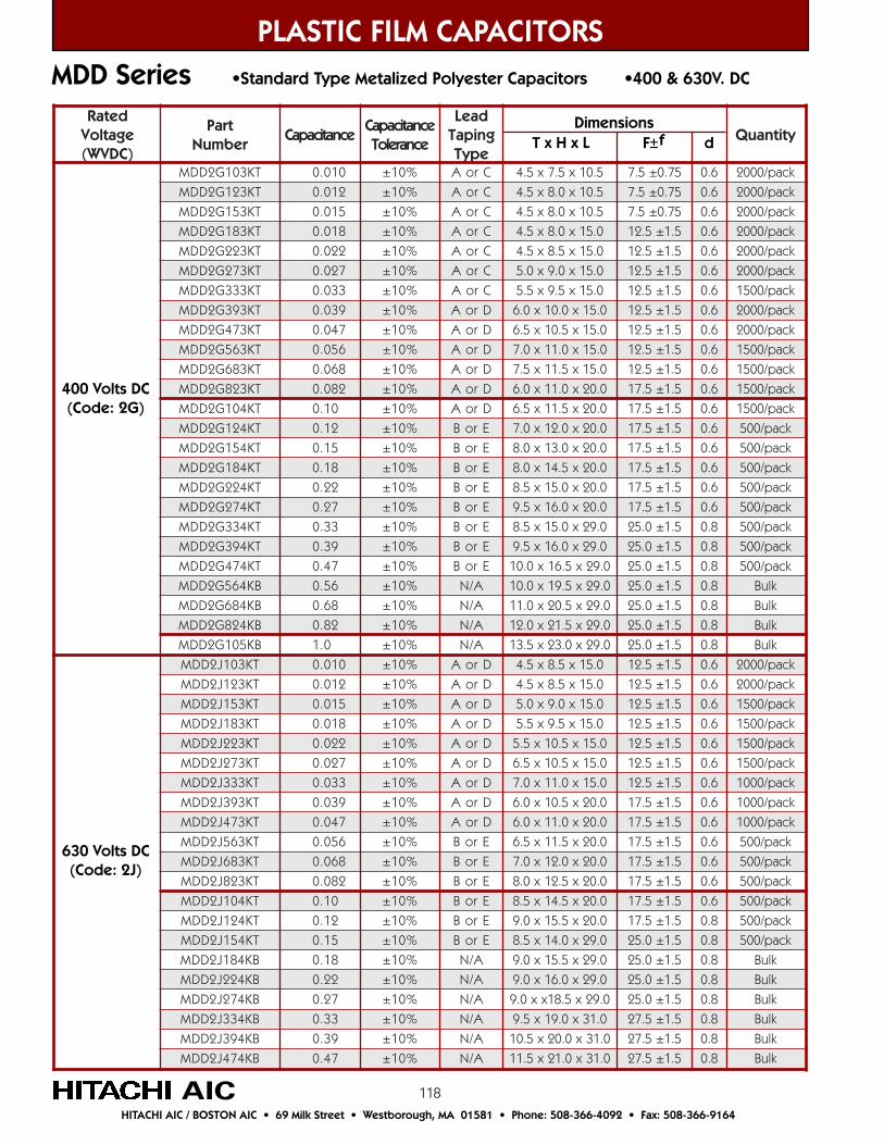
118
PLASTIC FILM CAPACITORS
AICHITACHI AIC / BOSTON AIC • 69 Milk Street • Westborough, MA 01581 • Phone: 508-366-4092 • Fax: 508-366-9164
MDD Series •Standard Type Metalized Polyester Capacitors •400 & 630V. DC
detaRegatloV)CDVW(
traPrebmuN
ecnaticapaCecnaticapaC
ecnareloT
daeLgnipaT
epyTytitnauQ
TK301G2DDM 010.0 %01± CroA 5.01x5.7x5.4 57.0±5.7 6.0 kcap/0002
TK321G2DDM 210.0 %01± CroA 5.01x0.8x5.4 57.0±5.7 6.0 kcap/0002
TK351G2DDM 510.0 %01± CroA 5.01x0.8x5.4 57.0±5.7 6.0 kcap/0002
TK381G2DDM 810.0 %01± CroA 0.51x0.8x5.4 5.1±5.21 6.0 kcap/0002
TK322G2DDM 220.0 %01± CroA 0.51x5.8x5.4 5.1±5.21 6.0 kcap/0002
TK372G2DDM 720.0 %01± CroA 0.51x0.9x0.5 5.1±5.21 6.0 kcap/0002
TK333G2DDM 330.0 %01± CroA 0.51x5.9x5.5 5.1±5.21 6.0 kcap/0051
TK393G2DDM 930.0 %01± DroA 0.51x0.01x0.6 5.1±5.21 6.0 kcap/0002
TK374G2DDM 740.0 %01± DroA 0.51x5.01x5.6 5.1±5.21 6.0 kcap/0002
TK365G2DDM 650.0 %01± DroA 0.51x0.11x0.7 5.1±5.21 6.0 kcap/0051
TK386G2DDM 860.0 %01± DroA 0.51x5.11x5.7 5.1±5.21 6.0 kcap/0051
TK328G2DDM 280.0 %01± DroA 0.02x0.11x0.6 5.1±5.71 6.0 kcap/0051
TK401G2DDM 01.0 %01± DroA 0.02x5.11x5.6 5.1±5.71 6.0 kcap/0051
TK421G2DDM 21.0 %01± EroB 0.02x0.21x0.7 5.1±5.71 6.0 kcap/005
TK451G2DDM 51.0 %01± EroB 0.02x0.31x0.8 5.1±5.71 6.0 kcap/005
TK481G2DDM 81.0 %01± EroB 0.02x5.41x0.8 5.1±5.71 6.0 kcap/005
TK422G2DDM 22.0 %01± EroB 0.02x0.51x5.8 5.1±5.71 6.0 kcap/005
TK472G2DDM 72.0 %01± EroB 0.02x0.61x5.9 5.1±5.71 6.0 kcap/005
TK433G2DDM 33.0 %01± EroB 0.92x0.51x5.8 5.1±0.52 8.0 kcap/005
TK493G2DDM 93.0 %01± EroB 0.92x0.61x5.9 5.1±0.52 8.0 kcap/005
TK474G2DDM 74.0 %01± EroB 0.92x5.61x0.01 5.1±0.52 8.0 kcap/005
BK465G2DDM 65.0 %01± A/N 0.92x5.91x0.01 5.1±0.52 8.0 kluB
BK486G2DDM 86.0 %01± A/N 0.92x5.02x0.11 5.1±0.52 8.0 kluB
BK428G2DDM 28.0 %01± A/N 0.92x5.12x0.21 5.1±0.52 8.0 kluB
BK501G2DDM 0.1 %01± A/N 0.92x0.32x5.31 5.1±0.52 8.0 kluB
TK301J2DDM 010.0 %01± DroA 0.51x5.8x5.4 5.1±5.21 6.0 kcap/0002
TK321J2DDM 210.0 %01± DroA 0.51x5.8x5.4 5.1±5.21 6.0 kcap/0002
TK351J2DDM 510.0 %01± DroA 0.51x0.9x0.5 5.1±5.21 6.0 kcap/0051
TK381J2DDM 810.0 %01± DroA 0.51x5.9x5.5 5.1±5.21 6.0 kcap/0051
TK322J2DDM 220.0 %01± DroA 0.51x5.01x5.5 5.1±5.21 6.0 kcap/0051
TK372J2DDM 720.0 %01± DroA 0.51x5.01x5.6 5.1±5.21 6.0 kcap/0051
TK333J2DDM 330.0 %01± DroA 0.51x0.11x0.7 5.1±5.21 6.0 kcap/0001
TK393J2DDM 930.0 %01± DroA 0.02x5.01x0.6 5.1±5.71 6.0 kcap/0001
TK374J2DDM 740.0 %01± DroA 0.02x0.11x0.6 5.1±5.71 6.0 kcap/0001
TK365J2DDM 650.0 %01± EroB 0.02x5.11x5.6 5.1±5.71 6.0 kcap/005
TK386J2DDM 860.0 %01± EroB 0.02x0.21x0.7 5.1±5.71 6.0 kcap/005
TK328J2DDM 280.0 %01± EroB 0.02x5.21x0.8 5.1±5.71 6.0 kcap/005
TK401J2DDM 01.0 %01± EroB 0.02x5.41x5.8 5.1±5.71 6.0 kcap/005
TK421J2DDM 21.0 %01± EroB 0.02x5.51x0.9 5.1±5.71 8.0 kcap/005
TK451J2DDM 51.0 %01± EroB 0.92x0.41x5.8 5.1±0.52 8.0 kcap/005
BK481J2DDM 81.0 %01± A/N 0.92x5.51x0.9 5.1±0.52 8.0 kluB
BK422J2DDM 22.0 %01± A/N 0.92x0.61x0.9 5.1±0.52 8.0 kluB
BK472J2DDM 72.0 %01± A/N 0.92x5.81xx0.9 5.1±0.52 8.0 kluB
BK433J2DDM 33.0 %01± A/N 0.13x0.91x5.9 5.1±5.72 8.0 kluB
BK493J2DDM 93.0 %01± A/N 0.13x0.02x5.01 5.1±5.72 8.0 kluB
BK474J2DDM 74.0 %01± A/N 0.13x0.12x5.11 5.1±5.72 8.0 kluB
400 Volts DC(Code: 2G)
630 Volts DC(Code: 2J)
Dimensions T x H x L F±f d
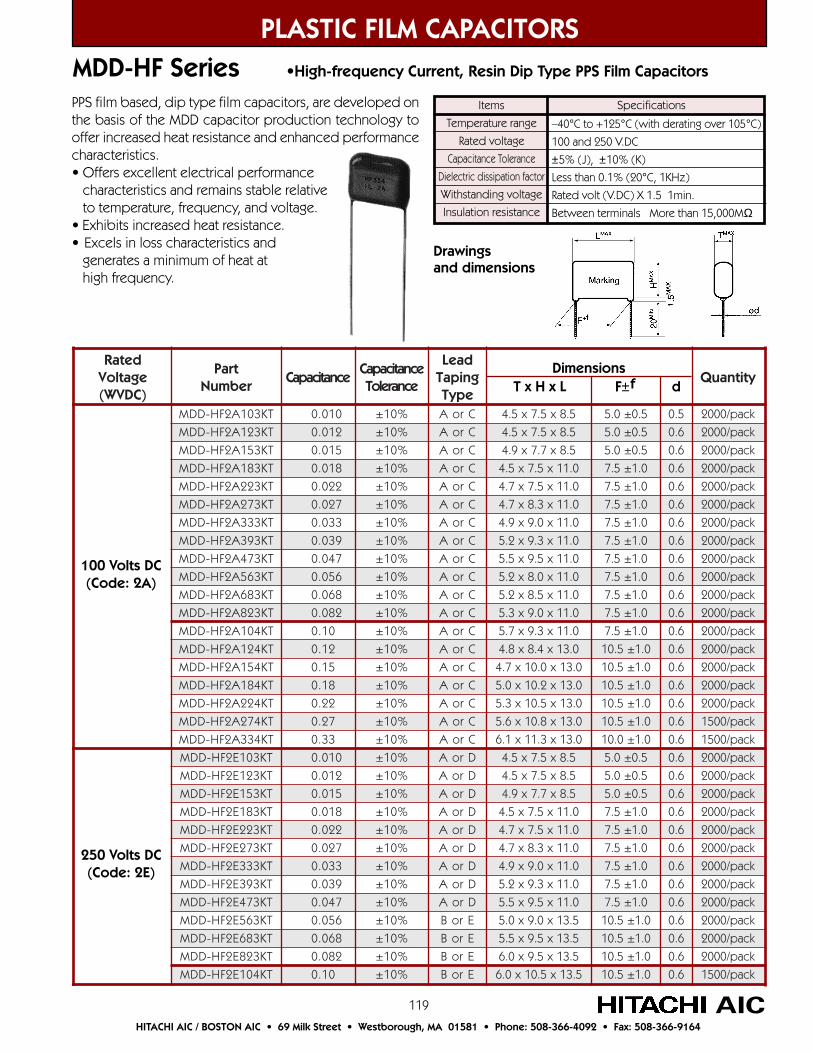
119
PLASTIC FILM CAPACITORS
AICHITACHI AIC / BOSTON AIC • 69 Milk Street • Westborough, MA 01581 • Phone: 508-366-4092 • Fax: 508-366-9164
MDD-HF Series •High-frequency Current, Resin Dip Type PPS Film Capacitors
Items
Temperature range
Rated voltage
Capacitance Tolerance
Dielectric dissipation factor
Withstanding voltage
Insulation resistance
–40°C to +125°C (with derating over 105°C)
100 and 250 V.DC
±5% (J), ±10% (K)
Less than 0.1% (20°C, 1KHz)
Rated volt (V.DC) X 1.5 1min.
Between terminals More than 15,000MΩ
SpecificationsPPS film based, dip type film capacitors, are developed onthe basis of the MDD capacitor production technology tooffer increased heat resistance and enhanced performancecharacteristics.• Offers excellent electrical performance characteristics and remains stable relative to temperature, frequency, and voltage.• Exhibits increased heat resistance.• Excels in loss characteristics and generates a minimum of heat at high frequency.
Drawingsand dimensions
detaRegatloV)CDVW(
traPrebmuN
ecnaticapaCecnaticapaC
ecnareloT
daeLgnipaT
epyTytitnauQ
TK301A2FH-DDM 010.0 %01± CroA 5.8x5.7x5.4 5.0±0.5 5.0 kcap/0002
TK321A2FH-DDM 210.0 %01± CroA 5.8x5.7x5.4 5.0±0.5 6.0 kcap/0002
TK351A2FH-DDM 510.0 %01± CroA 5.8x7.7x9.4 5.0±0.5 6.0 kcap/0002
TK381A2FH-DDM 810.0 %01± CroA 0.11x5.7x5.4 0.1±5.7 6.0 kcap/0002
TK322A2FH-DDM 220.0 %01± CroA 0.11x5.7x7.4 0.1±5.7 6.0 kcap/0002
TK372A2FH-DDM 720.0 %01± CroA 0.11x3.8x7.4 0.1±5.7 6.0 kcap/0002
TK333A2FH-DDM 330.0 %01± CroA 0.11x0.9x9.4 0.1±5.7 6.0 kcap/0002
TK393A2FH-DDM 930.0 %01± CroA 0.11x3.9x2.5 0.1±5.7 6.0 kcap/0002
TK374A2FH-DDM 740.0 %01± CroA 0.11x5.9x5.5 0.1±5.7 6.0 kcap/0002
TK365A2FH-DDM 650.0 %01± CroA 0.11x0.8x2.5 0.1±5.7 6.0 kcap/0002
TK386A2FH-DDM 860.0 %01± CroA 0.11x5.8x2.5 0.1±5.7 6.0 kcap/0002
TK328A2FH-DDM 280.0 %01± CroA 0.11x0.9x3.5 0.1±5.7 6.0 kcap/0002
TK401A2FH-DDM 01.0 %01± CroA 0.11x3.9x7.5 0.1±5.7 6.0 kcap/0002
TK421A2FH-DDM 21.0 %01± CroA 0.31x4.8x8.4 0.1±5.01 6.0 kcap/0002
TK451A2FH-DDM 51.0 %01± CroA 0.31x0.01x7.4 0.1±5.01 6.0 kcap/0002
TK481A2FH-DDM 81.0 %01± CroA 0.31x2.01x0.5 0.1±5.01 6.0 kcap/0002
TK422A2FH-DDM 22.0 %01± CroA 0.31x5.01x3.5 0.1±5.01 6.0 kcap/0002
TK472A2FH-DDM 72.0 %01± CroA 0.31x8.01x6.5 0.1±5.01 6.0 kcap/0051
TK433A2FH-DDM 33.0 %01± CroA 0.31x3.11x1.6 0.1±0.01 6.0 kcap/0051
TK301E2FH-DDM 010.0 %01± DroA 5.8x5.7x5.4 5.0±0.5 6.0 kcap/0002
TK321E2FH-DDM 210.0 %01± DroA 5.8x5.7x5.4 5.0±0.5 6.0 kcap/0002
TK351E2FH-DDM 510.0 %01± DroA 5.8x7.7x9.4 5.0±0.5 6.0 kcap/0002
TK381E2FH-DDM 810.0 %01± DroA 0.11x5.7x5.4 0.1±5.7 6.0 kcap/0002
TK322E2FH-DDM 220.0 %01± DroA 0.11x5.7x7.4 0.1±5.7 6.0 kcap/0002
TK372E2FH-DDM 720.0 %01± DroA 0.11x3.8x7.4 0.1±5.7 6.0 kcap/0002
TK333E2FH-DDM 330.0 %01± DroA 0.11x0.9x9.4 0.1±5.7 6.0 kcap/0002
TK393E2FH-DDM 930.0 %01± DroA 0.11x3.9x2.5 0.1±5.7 6.0 kcap/0002
TK374E2FH-DDM 740.0 %01± DroA 0.11x5.9x5.5 0.1±5.7 6.0 kcap/0002
TK365E2FH-DDM 650.0 %01± EroB 5.31x0.9x0.5 0.1±5.01 6.0 kcap/0002
TK386E2FH-DDM 860.0 %01± EroB 5.31x5.9x5.5 0.1±5.01 6.0 kcap/0002
TK328E2FH-DDM 280.0 %01± EroB 5.31x5.9x0.6 0.1±5.01 6.0 kcap/0002
TK401E2FH-DDM 01.0 %01± EroB 5.31x5.01x0.6 0.1±5.01 6.0 kcap/0051
100 Volts DC(Code: 2A)
250 Volts DC(Code: 2E)
Dimensions T x H x L F±f d
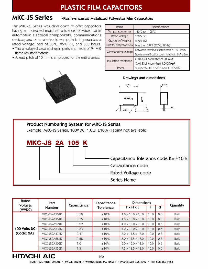
120
MKC-JS Series •Resin-encased Metalized Polyester Film Capacitors
PLASTIC FILM CAPACITORS
AICHITACHI AIC / BOSTON AIC • 69 Milk Street • Westborough, MA 01581 • Phone: 508-366-4092 • Fax: 508-366-9164
Items
Temperature range
Rated voltage
Capacitance Tolerance
Dielectric dissipation factor
Withstanding voltage
Insulation resistance
Others
–40°C to +105°C
100 V.DC
±10% (K),
Less than 0.8% (20°C, 1KHz)
Between terminals Rated volt X 1.5 1min.
Between terminal & outside covering Rated volt x 2.0/1 to 5 sec.
CR≤0.33µF More than 9,000MΩCR>0.33µF More than 3,000Ω•µF
Subject to JIS C 5115 and JIS C 5102
SpecificationsThe MKC-JS Series was developed to offer capacitorshaving an increased moisture resistance for wide use inautomotive electrical components, communicationsdevices, and other electronic equipment. It guarantees arated voltage load of 85°C, 85% RH, and 500 hours.• The employed case and resin parts are made of 94 V-0 flame resistant material.• A lead pitch of 10 mm is employed for the entire series.
detaRegatloV)CDVW(
traPrebmuN
ecnaticapaCecnaticapaC
ecnareloTytitnauQ
K401A2SJ-CKM 01.0 %01± 0.31x0.01x0.4 0.01 6.0 kluB
K451A2SJ-CKM 51.0 %01± 0.31x0.01x0.4 0.01 6.0 kluB
K422A2SJ-CKM 22.0 %01± 0.31x0.01x0.4 0.01 6.0 kluB
K433A2SJ-CKM 33.0 %01± 0.31x0.01x0.4 0.01 6.0 kluB
K474A2SJ-CKM 74.0 %01± 0.31x5.11x0.5 0.01 6.0 kluB
K486A2SJ-CKM 86.0 %01± 0.31x5.11x0.5 0.01 6.0 kluB
K501A2SJ-CKM 0.1 %01± 0.31x0.21x0.6 0.01 6.0 kluB
K551A2SJ-CKM 5.1 %01± 0.31x5.31x5.7 0.01 6.0 kluB
100 Volts DC(Code: 2A)
Drawings and dimensions
Product Numbering System for MKC-JS SeriesExample: MKC-JS Series, 100V.DC, 1.0µF ±10% (Taping not available)
Capacitance Tolerance code K= ±10%
Capacitance code
Rated Voltage code
Series Name
MKC-JS 2A 105 K
Dimensions T x H x L F d

121
PLASTIC FILM CAPACITORS
AICHITACHI AIC / BOSTON AIC • 69 Milk Street • Westborough, MA 01581 • Phone: 508-366-4092 • Fax: 508-366-9164
MDDA-P Series •High Frequency. Large Current, Resin Dipped Polypropylene Film Capacitors
detaRegatloV)CDVW(
traPrebmuN
ecnaticapaCecnaticapaC
ecnareloTytitnauQ
J401E2P-ADDM 01.0 %5± 0.81x5.01x0.6 0.51 6.0 kluB
K401E2P-ADDM 01.0 %01± 0.81x5.01x0.6 0.51 6.0 kluB
J421E2P-ADDM 21.0 %5± 0.81x5.11x0.6 0.51 6.0 kluB
K421E2P-ADDM 21.0 %01± 0.81x5.11x0.6 0.51 6.0 kluB
J451E2P-ADDM 51.0 %5± 0.81x0.21x0.7 0.51 6.0 kluB
K451E2P-ADDM 51.0 %01± 0.81x0.21x0.7 0.51 6.0 kluB
J481E2P-ADDM 81.0 %5± 0.81x5.21x5.7 0.51 6.0 kluB
K481E2P-ADDM 81.0 %01± 0.81x5.21x5.7 0.51 6.0 kluB
J422E2P-ADDM 22.0 %5± 0.81x0.31x0.8 0.51 6.0 kluB
K422E2P-ADDM 22.0 %01± 0.81x0.31x0.8 0.51 6.0 kluB
J472E2P-ADDM 72.0 %5± 0.81x4.31x5.8 0.51 6.0 kluB
K472E2P-ADDM 72.0 %01± 0.81x4.31x5.8 0.51 6.0 kluB
J433E2P-ADDM 33.0 %5± 0.81x0.51x5.8 0.51 6.0 kluB
K433E2P-ADDM 33.0 %01± 0.81x0.51x5.8 0.51 6.0 kluB
J493E2P-ADDM 93.0 %5± 0.62x5.31x0.7 5.22 8.0 kluB
K493E2P-ADDM 93.0 %01± 0.62x5.31x0.7 5.22 8.0 kluB
J474E2P-ADDM 74.0 %5± 0.62x0.41x5.7 5.22 8.0 kluB
K474E2P-ADDM 74.0 %01± 0.62x0.41x5.7 5.22 8.0 kluB
J465E2P-ADDM 65.0 %5± 0.62x5.41x0.8 5.22 8.0 kluB
K465E2P-ADDM 65.0 %01± 0.62x5.41x0.8 5.22 8.0 kluB
J486E2P-ADDM 86.0 %5± 0.62x5.51x5.8 5.22 8.0 kluB
K486E2P-ADDM 86.0 %01± 0.62x5.51x5.8 5.22 8.0 kluB
J428E2P-ADDM 28.0 %5± 0.62x0.61x5.9 5.22 8.0 kluB
K428E2P-ADDM 28.0 %01± 0.62x0.61x5.9 5.22 8.0 kluB
J501E2P-ADDM 0.1 %5± 0.13x0.61x5.9 5.72 8.0 kluB
K501E2P-ADDM 0.1 %01± 0.13x0.61x5.9 5.72 8.0 kluB
J521E2P-ADDM 2.1 %5± 0.13x0.71x0.01 5.72 8.0 kluB
K521E2P-ADDM 2.1 %01± 0.13x0.71x0.01 5.72 8.0 kluB
J551E2P-ADDM 5.1 %5± 0.13x0.81x0.11 5.72 8.0 kluB
K551E2P-ADDM 5.1 %01± 0.13x0.81x0.11 5.72 8.0 kluB
J581E2P-ADDM 8.1 %5± 5.13x0.91x0.21 5.72 8.0 kluB
K581E2P-ADDM 8.1 %01± 5.13x0.91x0.21 5.72 8.0 kluB
Dimensions T x H x L F d
250 Volts DC(Code: 2E)
Drawings and dimensions
The MDDA-P Series ia a metalized polypropylene filmcapacitor suitable for high frequency and large currentcircuits. Has S-shape correction for TV.
Items
Temperature range
Rated voltage
Capacitance Tolerance
Dielectric dissipation factor
Withstanding voltage
Insulation resistance
Others
–40°C to +85°C (with derating over 85°C)
250V. DC (MDDA-P), 400V. DC (MDDB-P)
±5% (J), ±10% (K)
Less than 0.1% (20°C, 1KHz)
Between terminals Rated volt X 1.5 1min.
Between terminal & outside coating Rated volt x 2.0, 1 to 5 sec.
CR≤0.33µF More than 30,000MΩCR>0.33µF More than 10,000Ω•µF
Subject to EIAJ RC 2347 and JIS C 5102
Specifications
• Metalizied polypropylene film is used as a dielectric, forming a non-inductive winding for low loss.• Excellent temperature and frequency characteristics.• Exterior coating is flame retardant epoxy resin.
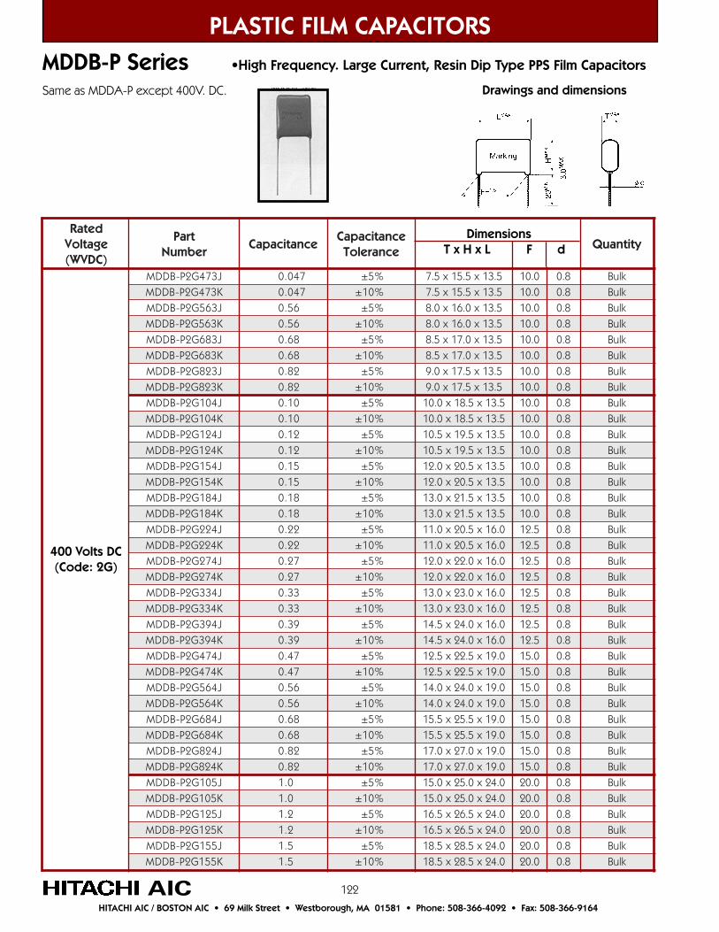
122
detaRegatloV)CDVW(
traPrebmuN
ecnaticapaCecnaticapaC
ecnareloTytitnauQ
J374G2P-BDDM 740.0 %5± 5.31x5.51x5.7 0.01 8.0 kluBK374G2P-BDDM 740.0 %01± 5.31x5.51x5.7 0.01 8.0 kluBJ365G2P-BDDM 65.0 %5± 5.31x0.61x0.8 0.01 8.0 kluBK365G2P-BDDM 65.0 %01± 5.31x0.61x0.8 0.01 8.0 kluBJ386G2P-BDDM 86.0 %5± 5.31x0.71x5.8 0.01 8.0 kluBK386G2P-BDDM 86.0 %01± 5.31x0.71x5.8 0.01 8.0 kluBJ328G2P-BDDM 28.0 %5± 5.31x5.71x0.9 0.01 8.0 kluBK328G2P-BDDM 28.0 %01± 5.31x5.71x0.9 0.01 8.0 kluBJ401G2P-BDDM 01.0 %5± 5.31x5.81x0.01 0.01 8.0 kluBK401G2P-BDDM 01.0 %01± 5.31x5.81x0.01 0.01 8.0 kluBJ421G2P-BDDM 21.0 %5± 5.31x5.91x5.01 0.01 8.0 kluBK421G2P-BDDM 21.0 %01± 5.31x5.91x5.01 0.01 8.0 kluBJ451G2P-BDDM 51.0 %5± 5.31x5.02x0.21 0.01 8.0 kluBK451G2P-BDDM 51.0 %01± 5.31x5.02x0.21 0.01 8.0 kluBJ481G2P-BDDM 81.0 %5± 5.31x5.12x0.31 0.01 8.0 kluBK481G2P-BDDM 81.0 %01± 5.31x5.12x0.31 0.01 8.0 kluBJ422G2P-BDDM 22.0 %5± 0.61x5.02x0.11 5.21 8.0 kluBK422G2P-BDDM 22.0 %01± 0.61x5.02x0.11 5.21 8.0 kluBJ472G2P-BDDM 72.0 %5± 0.61x0.22x0.21 5.21 8.0 kluBK472G2P-BDDM 72.0 %01± 0.61x0.22x0.21 5.21 8.0 kluBJ433G2P-BDDM 33.0 %5± 0.61x0.32x0.31 5.21 8.0 kluBK433G2P-BDDM 33.0 %01± 0.61x0.32x0.31 5.21 8.0 kluBJ493G2P-BDDM 93.0 %5± 0.61x0.42x5.41 5.21 8.0 kluBK493G2P-BDDM 93.0 %01± 0.61x0.42x5.41 5.21 8.0 kluBJ474G2P-BDDM 74.0 %5± 0.91x5.22x5.21 0.51 8.0 kluBK474G2P-BDDM 74.0 %01± 0.91x5.22x5.21 0.51 8.0 kluBJ465G2P-BDDM 65.0 %5± 0.91x0.42x0.41 0.51 8.0 kluBK465G2P-BDDM 65.0 %01± 0.91x0.42x0.41 0.51 8.0 kluBJ486G2P-BDDM 86.0 %5± 0.91x5.52x5.51 0.51 8.0 kluBK486G2P-BDDM 86.0 %01± 0.91x5.52x5.51 0.51 8.0 kluBJ428G2P-BDDM 28.0 %5± 0.91x0.72x0.71 0.51 8.0 kluBK428G2P-BDDM 28.0 %01± 0.91x0.72x0.71 0.51 8.0 kluBJ501G2P-BDDM 0.1 %5± 0.42x0.52x0.51 0.02 8.0 kluBK501G2P-BDDM 0.1 %01± 0.42x0.52x0.51 0.02 8.0 kluBJ521G2P-BDDM 2.1 %5± 0.42x5.62x5.61 0.02 8.0 kluBK521G2P-BDDM 2.1 %01± 0.42x5.62x5.61 0.02 8.0 kluBJ551G2P-BDDM 5.1 %5± 0.42x5.82x5.81 0.02 8.0 kluBK551G2P-BDDM 5.1 %01± 0.42x5.82x5.81 0.02 8.0 kluB
PLASTIC FILM CAPACITORS
AICHITACHI AIC / BOSTON AIC • 69 Milk Street • Westborough, MA 01581 • Phone: 508-366-4092 • Fax: 508-366-9164
MDDB-P Series •High Frequency. Large Current, Resin Dip Type PPS Film Capacitors
400 Volts DC(Code: 2G)
Same as MDDA-P except 400V. DC. Drawings and dimensions
Dimensions T x H x L F d
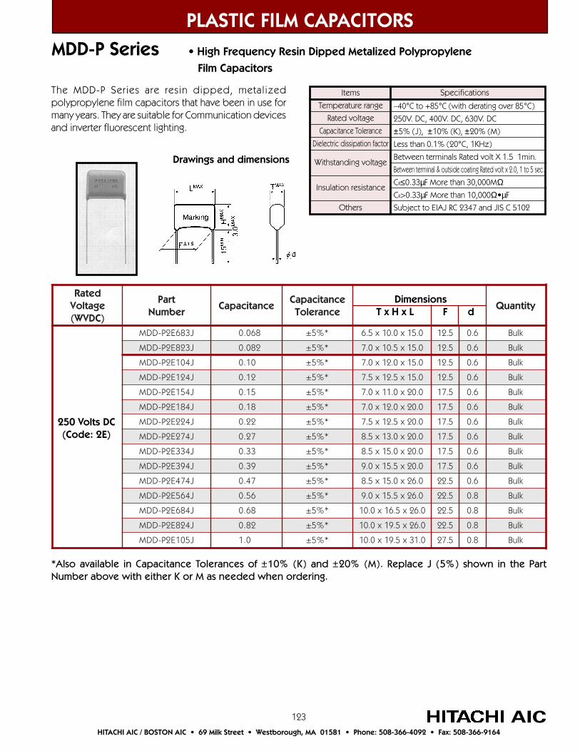
123
MDD-P Series • High Frequency Resin Dipped Metalized Polypropylene
Film Capacitors
PLASTIC FILM CAPACITORS
AICHITACHI AIC / BOSTON AIC • 69 Milk Street • Westborough, MA 01581 • Phone: 508-366-4092 • Fax: 508-366-9164
detaRegatloV)CDVW(
traPrebmuN
ecnaticapaCecnaticapaC
ecnareloTytitnauQ
J386E2P-DDM 860.0 *%5± 0.51x0.01x5.6 5.21 6.0 kluB
J328E2P-DDM 280.0 *%5± 0.51x5.01x0.7 5.21 6.0 kluB
J401E2P-DDM 01.0 *%5± 0.51x0.21x0.7 5.21 6.0 kluB
J421E2P-DDM 21.0 *%5± 0.51x5.21x5.7 5.21 6.0 kluB
J451E2P-DDM 51.0 *%5± 0.02x0.11x0.7 5.71 6.0 kluB
J481E2P-DDM 81.0 *%5± 0.02x0.21x0.7 5.71 6.0 kluB
J422E2P-DDM 22.0 *%5± 0.02x5.21x5.7 5.71 6.0 kluB
J472E2P-DDM 72.0 *%5± 0.02x0.31x5.8 5.71 6.0 kluB
J433E2P-DDM 33.0 *%5± 0.02x0.51x5.8 5.71 6.0 kluB
J493E2P-DDM 93.0 *%5± 0.02x5.51x0.9 5.71 6.0 kluB
J474E2P-DDM 74.0 *%5± 0.62x0.51x5.8 5.22 6.0 kluB
J465E2P-DDM 65.0 *%5± 0.62x5.51x0.9 5.22 8.0 kluB
J486E2P-DDM 86.0 *%5± 0.62x5.61x0.01 5.22 8.0 kluB
J428E2P-DDM 28.0 *%5± 0.62x5.91x0.01 5.22 8.0 kluB
J501E2P-DDM 0.1 *%5± 0.13x5.91x0.01 5.72 8.0 kluB
Dimensions T x H x L F d
250 Volts DC(Code: 2E)
Items
Temperature range
Rated voltage
Capacitance Tolerance
Dielectric dissipation factor
Withstanding voltage
Insulation resistance
Others
–40°C to +85°C (with derating over 85°C)
250V. DC, 400V. DC, 630V. DC
±5% (J), ±10% (K), ±20% (M)
Less than 0.1% (20°C, 1KHz)
Between terminals Rated volt X 1.5 1min.
Between terminal & outside coating Rated volt x 2.0, 1 to 5 sec.
CR≤0.33µF More than 30,000MΩCR>0.33µF More than 10,000Ω•µF
Subject to EIAJ RC 2347 and JIS C 5102
SpecificationsThe MDD-P Series are resin dipped, metalizedpolypropylene film capacitors that have been in use formany years. They are suitable for Communication devicesand inverter fluorescent lighting.
Drawings and dimensions
*Also available in Capacitance Tolerances of ±10% (K) and ±20% (M). Replace J (5%) shown in the PartNumber above with either K or M as needed when ordering.
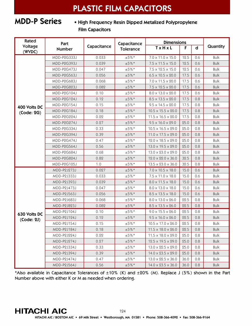
124
detaRegatloV)CDVW(
traPrebmuN
ecnaticapaCecnaticapaC
ecnareloTytitnauQ
J333G2P-DDM 330.0 *%5± 0.51x0.11x0.7 5.21 6.0 kluB
J393G2P-DDM 930.0 *%5± 0.51x5.11x5.7 5.21 6.0 kluB
J374G2P-DDM 740.0 *%5± 0.51x5.21x5.7 5.21 6.0 kluB
J365G2P-DDM 650.0 *%5± 0.02x5.01x5.6 5.71 6.0 kluB
J386G2P-DDM 860.0 *%5± 0.02x5.11x0.7 5.71 6.0 kluB
J328G2P-DDM 280.0 *%5± 0.02x5.21x5.7 5.71 6.0 kluB
J401G2P-DDM 01.0 *%5± 0.02x0.31x0.8 5.71 6.0 kluB
J421G2P-DDM 21.0 *%5± 0.02x5.31x5.8 5.71 8.0 kluB
J451G2P-DDM 51.0 *%5± 0.02x5.41x5.9 5.71 8.0 kluB
J481G2P-DDM 81.0 *%5± 0.02x5.51x5.01 5.71 8.0 kluB
J422G2P-DDM 22.0 *%5± 0.02x5.61x5.11 5.71 8.0 kluB
J472G2P-DDM 72.0 *%5± 0.92x0.61x5.9 0.52 8.0 kluB
J433G2P-DDM 33.0 *%5± 0.92x5.61x5.01 0.52 8.0 kluB
J493G2P-DDM 93.0 *%5± 0.92x5.71x0.11 0.52 8.0 kluB
J474G2P-DDM 74.0 *%5± 0.92x5.81x0.21 0.52 8.0 kluB
J465G2P-DDM 65.0 *%5± 0.92x5.91x0.31 0.52 8.0 kluB
J486G2P-DDM 86.0 *%5± 0.92x0.32x0.31 0.52 8.0 kluB
J428G2P-DDM 28.0 *%5± 0.63x0.22x0.21 5.23 8.0 kluB
J501G2P-DDM 0.1 *%5± 0.63x0.32x5.31 5.23 8.0 kluB
J372J2P-DDM 720.0 *%5± 0.81x5.01x0.7 0.51 6.0 kluB
J333J2P-DDM 330.0 *%5± 0.81x0.11x5.7 0.51 6.0 kluB
J393J2P-DDM 930.0 *%5± 0.81x5.11x0.8 0.51 6.0 kluB
J374J2P-DDM 740.0 *%5± 0.81x0.31x0.8 0.51 6.0 kluB
J365J2P-DDM 650.0 *%5± 0.81x5.31x5.8 0.51 6.0 kluB
J386J2P-DDM 860.0 *%5± 0.62x0.31x0.8 5.22 8.0 kluB
J328J2P-DDM 280.0 *%5± 0.62x5.31x5.8 5.22 8.0 kluB
J401J2P-DDM 01.0 *%5± 0.62x5.51x0.9 5.22 8.0 kluB
J421J2P-DDM 21.0 *%5± 0.62x0.61x5.9 5.22 8.0 kluB
J451J2P-DDM 51.0 *%5± 0.62x0.71x5.01 5.22 8.0 kluB
J481J2P-DDM 81.0 *%5± 0.62x0.81x5.11 5.22 8.0 kluB
J422J2P-DDM 22.0 *%5± 0.92x0.81x5.11 0.52 8.0 kluB
J472J2P-DDM 72.0 *%5± 0.92x5.91x5.21 0.52 8.0 kluB
J433J2P-DDM 33.0 *%5± 0.92x5.22x0.31 0.52 8.0 kluB
J493J2P-DDM 93.0 *%5± 0.92x5.32x0.41 0.52 8.0 kluB
J474J2P-DDM 74.0 *%5± 0.63x5.22x0.31 0.63 8.0 kluB
J465J2P-DDM 65.0 *%5± 0.63x5.32x0.41 0.63 8.0 kluB
MDD-P Series • High Frequency Resin Dipped Metalized Polypropylene
Film Capacitors
PLASTIC FILM CAPACITORS
AICHITACHI AIC / BOSTON AIC • 69 Milk Street • Westborough, MA 01581 • Phone: 508-366-4092 • Fax: 508-366-9164
Dimensions T x H x L F d
630 Volts DC(Code: 2J)
*Also available in Capacitance Tolerances of ±10% (K) and ±20% (M). Replace J (5%) shown in the PartNumber above with either K or M as needed when ordering.
400 Volts DC(Code: 2G)
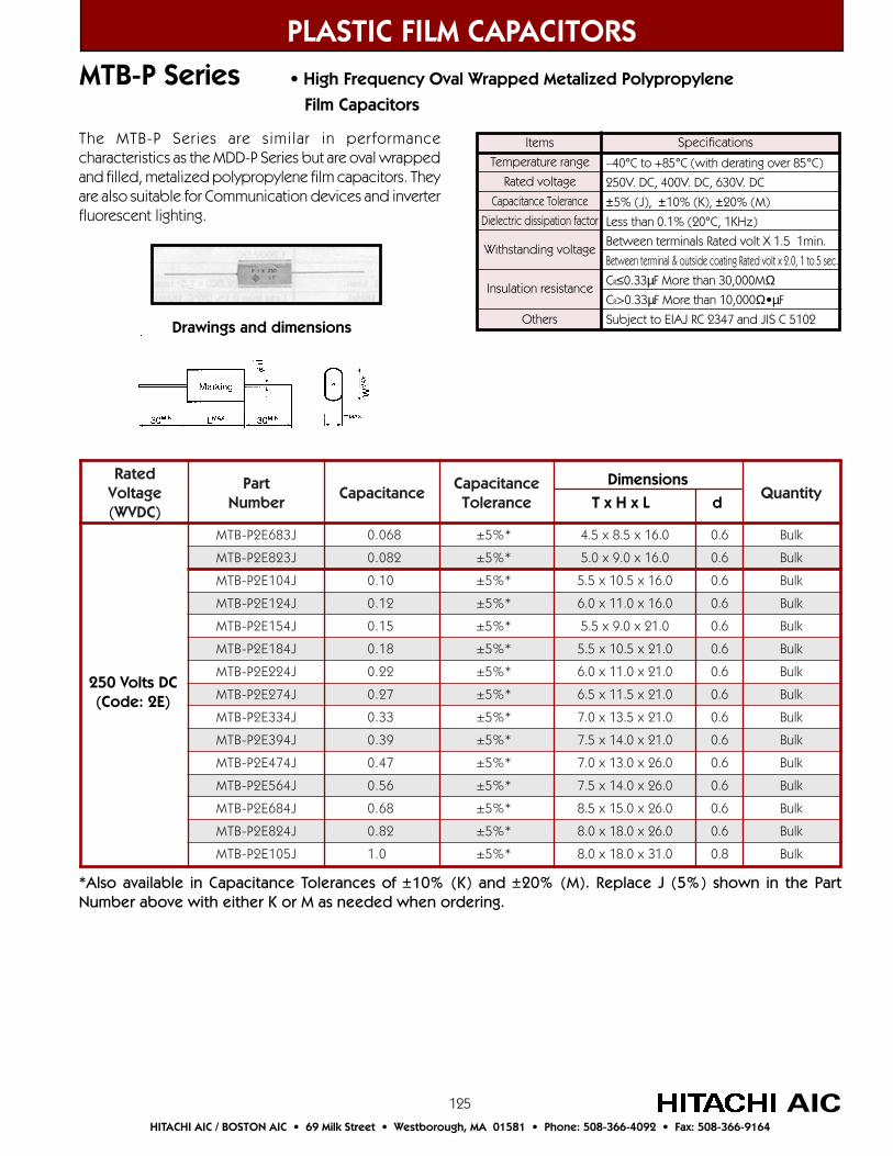
125
MTB-P Series • High Frequency Oval Wrapped Metalized Polypropylene
Film Capacitors
PLASTIC FILM CAPACITORS
AICHITACHI AIC / BOSTON AIC • 69 Milk Street • Westborough, MA 01581 • Phone: 508-366-4092 • Fax: 508-366-9164
Items
Temperature range
Rated voltage
Capacitance Tolerance
Dielectric dissipation factor
Withstanding voltage
Insulation resistance
Others
–40°C to +85°C (with derating over 85°C)
250V. DC, 400V. DC, 630V. DC
±5% (J), ±10% (K), ±20% (M)
Less than 0.1% (20°C, 1KHz)
Between terminals Rated volt X 1.5 1min.
Between terminal & outside coating Rated volt x 2.0, 1 to 5 sec.
CR≤0.33µF More than 30,000MΩCR>0.33µF More than 10,000Ω•µF
Subject to EIAJ RC 2347 and JIS C 5102
SpecificationsThe MTB-P Series are similar in performancecharacteristics as the MDD-P Series but are oval wrappedand filled, metalized polypropylene film capacitors. Theyare also suitable for Communication devices and inverterfluorescent lighting.
Drawings and dimensions
*Also available in Capacitance Tolerances of ±10% (K) and ±20% (M). Replace J (5%) shown in the PartNumber above with either K or M as needed when ordering.
detaRegatloV)CDVW(
traPrebmuN
ecnaticapaCecnaticapaC
ecnareloTytitnauQ
J386E2P-BTM 860.0 *%5± 0.61x5.8x5.4 6.0 kluB
J328E2P-BTM 280.0 *%5± 0.61x0.9x0.5 6.0 kluB
J401E2P-BTM 01.0 *%5± 0.61x5.01x5.5 6.0 kluB
J421E2P-BTM 21.0 *%5± 0.61x0.11x0.6 6.0 kluB
J451E2P-BTM 51.0 *%5± 0.12x0.9x5.5 6.0 kluB
J481E2P-BTM 81.0 *%5± 0.12x5.01x5.5 6.0 kluB
J422E2P-BTM 22.0 *%5± 0.12x0.11x0.6 6.0 kluB
J472E2P-BTM 72.0 *%5± 0.12x5.11x5.6 6.0 kluB
J433E2P-BTM 33.0 *%5± 0.12x5.31x0.7 6.0 kluB
J493E2P-BTM 93.0 *%5± 0.12x0.41x5.7 6.0 kluB
J474E2P-BTM 74.0 *%5± 0.62x0.31x0.7 6.0 kluB
J465E2P-BTM 65.0 *%5± 0.62x0.41x5.7 6.0 kluB
J486E2P-BTM 86.0 *%5± 0.62x0.51x5.8 6.0 kluB
J428E2P-BTM 28.0 *%5± 0.62x0.81x0.8 6.0 kluB
J501E2P-BTM 0.1 *%5± 0.13x0.81x0.8 8.0 kluB
250 Volts DC(Code: 2E)
Dimensions
T x H x L d

126
detaRegatloV)CDVW(
traPrebmuN
ecnaticapaCecnaticapaC
ecnareloTytitnauQ
J333G2P-BTM 330.0 *%5± 0.61x0.9x5.5 6.0 kluB
J393G2P-BTM 930.0 *%5± 0.61x5.9x0.6 6.0 kluB
J374G2P-BTM 740.0 *%5± 0.61x0.11x0.6 6.0 kluB
J365G2P-BTM 650.0 *%5± 0.12x0.9x0.5 6.0 kluB
J386G2P-BTM 860.0 *%5± 0.12x0.01x0.5 6.0 kluB
J328G2P-BTM 280.0 *%5± 0.12x5.01x5.5 6.0 kluB
J401G2P-BTM 01.0 *%5± 0.12x0.11x5.6 6.0 kluB
J421G2P-BTM 21.0 *%5± 012x0.21x0.7 6.0 kluB
J451G2P-BTM 51.0 *%5± 0.12x0.31x0.8 6.0 kluB
J481G2P-BTM 81.0 *%5± 0.12x5.31x5.8 6.0 kluB
J422G2P-BTM 22.0 *%5± 0.12x5.41x5.9 6.0 kluB
J472G2P-BTM 72.0 *%5± 0.92x0.41x5.7 8.0 kluB
J433G2P-BTM 33.0 *%5± 0.92x0.51x5.8 8.0 kluB
J493G2P-BTM 93.0 *%5± 0.92x5.51x5.9 8.0 kluB
J474G2P-BTM 74.0 *%5± 0.92x5.61x5.01 8.0 kluB
J465G2P-BTM 65.0 *%5± 0.92x5.71x5.11 8.0 kluB
J486G2P-BTM 86.0 *%5± 0.92x0.12x5.11 8.0 kluB
J428G2P-BTM 28.0 *%5± 0.73x0.02x5.01 8.0 kluB
J501G2P-BTM 0.1 *%5± 0.73x0.12x0.21 8.0 kluB
J372J2P-BTM 720.0 *%5± 0.02x0.9x0.5 6.0 kluB
J333J2P-BTM 330.0 *%5± 0.02x5.9x5.5 6.0 kluB
J393J2P-BTM 930.0 *%5± 0.02x0.01x0.6 6.0 kluB
J374J2P-BTM 740.0 *%5± 0.02x5.11x5.6 6.0 kluB
J365J2P-BTM 650.0 *%5± 0.02x0.21x0.7 6.0 kluB
J386J2P-BTM 860.0 *%5± 0.62x0.11x0.6 6.0 kluB
J328J2P-BTM 280.0 *%5± 0.62x5.11x0.7 8.0 kluB
J401J2P-BTM 01.0 *%5± 0.62x5.21x5.7 8.0 kluB
J421J2P-BTM 21.0 *%5± 0.62x0.41x5.7 8.0 kluB
J451J2P-BTM 51.0 *%5± 0.62x0.51x0.9 8.0 kluB
J481J2P-BTM 81.0 *%5± 0.62x061x5.9 8.0 kluB
J422J2P-BTM 22.0 *%5± 0.92x5.61x0.01 8.0 kluB
J472J2P-BTM 72.0 *%5± 0.92x5.71x0.11 8.0 kluB
J433J2P-BTM 33.0 *%5± 0.92x5.02x0.11 8.0 kluB
J493J2P-BTM 93.0 *%5± 0.92x0.22x0.11 8.0 kluB
J474J2P-BTM 74.0 *%5± 0.73x5.02x0.11 8.0 kluB
J465J2P-BTM 65.0 *%5± 0.73x0.22x5.21 8.0 kluB
MTB-P Series • High Frequency Oval Wrapped Metalized Polypropylene
Film Capacitors
PLASTIC FILM CAPACITORS
AICHITACHI AIC / BOSTON AIC • 69 Milk Street • Westborough, MA 01581 • Phone: 508-366-4092 • Fax: 508-366-9164
630 Volts DC(Code: 2J)
*Also available in Capacitance Tolerances of ±10% (K) and ±20% (M). Replace J (5%) shown in the PartNumber above with either K or M as needed when ordering.
400 Volts DC(Code: 2G)
Dimensions
T x H x L d

127
MTBS Series •Tape Wrapped Metalized Polyester Film Capacitors •Axial Leads
PLASTIC FILM CAPACITORS
AICHITACHI AIC / BOSTON AIC • 69 Milk Street • Westborough, MA 01581 • Phone: 508-366-4092 • Fax: 508-366-9164
Items
Temperature range
Rated voltage
Capacitance Tolerance
Dielectric dissipation factor
Withstanding voltage
Insulation resistance
Others
–40°C to +85°C
100 V.DC
±5% (J), ±10% (K), ±20% (M)
Less than 0.8% (20°C, 1KHz)
Rated volt (V. DC) X 1.5 1min.
CR≤0.33µF More than 9,000MΩCR>0.33µF More than 3,000Ω•µF
Subject to JIS C 5115 and JIS C 5102
SpecificationsThis series offers metalized film capacitors that have axialleads and exhibit excellent heat resistance and moistureresistance. These capacitors employ a metalized polyesterfilm dielectric and have a polyester-taped outer coveringand resin-sealed ends.
Drawings and dimensions
detaRegatloV)CDVW(
traPrebmuN
ecnaticapaCecnaticapaC
ecnareloTytitnauQ
K401A2SBTM 01.0 %01± 0.11x5.7x5.4 6.0 kluB
K421A2SBTM 21.0 %01± 0.41x0.8x0.4 6.0 kluB
K451A2SBTM 51.0 %01± 0.41x0.8x0.4 6.0 kluB
K481A2SBTM 81.0 %01± 0.41x0.8x0.4 6.0 kluB
K422A2SBTM 22.0 %01± 0.41x0.8x0.4 6.0 kluB
K472A2SBTM 72.0 %01± 0.41x0.8x0.4 6.0 kluB
K433A2SBTM 33.0 %01± 0.41x5.8x5.4 6.0 kluB
K493A2SBTM 93.0 %01± 0.41x0.9x0.5 6.0 kluB
K474A2SBTM 74.0 %01± 0.41x5.9x5.5 6.0 kluB
K465A2SBTM 65.0 %01± 0.02x5.9x5.4 6.0 kluB
K486A2SBTM 86.0 %01± 0.02x5.9x0.5 6.0 kluB
K428A2SBTM 28.0 %01± 0.02x0.01x0.5 6.0 kluB
K501A2SBTM 0.1 %01± 0.02x5.01x0.6 6.0 kluB
K521A2SBTM 2.1 %01± 0.02x5.11x5.6 6.0 kluB
K551A2SBTM 5.1 %01± 0.02x5.21x0.7 6.0 kluB
K581A2SBTM 8.1 %01± 0.22x0.21x0.7 8.0 kluB
K522A2SBTM 2.2 %01± 0.22x0.31x5.7 8.0 kluB
K572A2SBTM 7.2 %01± 0.22x0.41x5.8 8.0 kluB
K533A2SBTM 3.3 %01± 0.22x0.61x0.9 8.0 kluB
K593A2SBTM 9.3 %01± 0.22x0.71x0.01 8.0 kluB
K574A2SBTM 7.4 %01± 0.22x5.71x0.11 8.0 kluB
K565A2SBTM 6.5 %01± 0.62x5.71x0.11 8.0 kluB
K586A2SBTM 8.6 %01± 0.62x5.81x0.21 8.0 kluB
K528A2SBTM 2.8 %01± 0.13x5.61x5.01 8.0 kluB
K601A2SBTM 0.01 %01± 0.13x0.81x5.11 8.0 kluB
100 Volts DC(Code: 2A)
Dimensions T x H x L d

128
PLASTIC FILM CAPACITORS
AICHITACHI AIC / BOSTON AIC • 69 Milk Street • Westborough, MA 01581 • Phone: 508-366-4092 • Fax: 508-366-9164
MTB Series •Tape Wrapped Metalized Polyester Film Capacitors •Axial Leads
This series offers metalized film capacitors that have axialleads and exhibit excellent heat resistance and moistureresistance. These capacitors employ a metalized polyesterfilm dielectric and have a polyester-taped outer coveringand resin-sealed ends.
Drawings and dimensions
detaRegatloV)CDVW(
traPrebmuN
ecnaticapaCecnaticapaC
ecnareloTgnigakcaP
K374E2BTM 740.0 %01± 0.41x5.7x0.4 6.0 kluB
K386E2BTM 860.0 %01± 0.61x5.7x0.4 6.0 kluB
K401E2BTM 01.0 %01± 0.61x0.9x5.4 6.0 kluB
K421E2BTM 21.0 %01± 0.61x5.9x0.5 6.0 kluB
K451E2BTM 51.0 %01± 0.61x5.01x5.5 6.0 kluB
K481E2BTM 81.0 %01± 0.61x0.11x0.6 6.0 kluB
K422E2BTM 22.0 %01± 0.22x0.01x0.5 6.0 kluB
K472E2BTM 72.0 %01± 0.22x5.01x5.5 6.0 kluB
K433E2BTM 33.0 %01± 0.22x0.11x0.6 6.0 kluB
K493E2BTM 93.0 %01± 0.22x5.11x0.7 6.0 kluB
K474E2BTM 74.0 %01± 0.22x5.21x5.7 6.0 kluB
K465E2BTM 65.0 %01± 0.92x0.21x0.6 8.0 kluB
K486E2BTM 86.0 %01± 0.92x0.31x5.6 8.0 kluB
K428E2BTM 28.0 %01± 0.92x5.31x0.7 8.0 kluB
K501E2BTM 0.1 %01± 0.92x5.61x0.7 8.0 kluB
K521E2BTM 2.1 %01± 0.92x5.71x0.8 8.0 kluB
K551E2BTM 5.1 %01± 0.92x5.81x0.9 8.0 kluB
K581E2BTM 8.1 %01± 0.92x5.91x0.01 8.0 kluB
K522E2BTM 2.2 %01± 0.92x0.12x0.11 8.0 kluB
K572E2BTM 7.2 %01± 0.34x0.91x5.9 0.1 kluB
K533E2BTM 3.3 %01± 0.34x5.02x5.01 0.1 kluB
K593E2BTM 9.3 %01± 0.34x5.12x0.21 0.1 kluB
K574E2BTM 7.4 %01± 0.34x0.32x5.31 0.1 kluB
K565E2BTM 6.5 %01± 0.25x5.22x0.31 0.1 kluB
K586E2BTM 8.6 %01± 0.25x0.42x5.41 0.1 kluB
K528E2BTM 2.8 %01± 0.25x5.52x0.61 0.1 kluB
K601E2BTM 0.01 %01± 0.25x5.92x5.61 0.1 kluB
250 Volts DC(Code: 2E)
Items
Temperature range
Rated voltage
Capacitance Tolerance
Dielectric dissipation factor
Withstanding voltage
Insulation resistance
Others
–40°C to +85°C
100 V.DC
±5% (J), ±10% (K), ±20% (M)
Less than 0.8% (20°C, 1KHz)
Rated volt (V. DC) X 1.5 1min.
CR≤0.33µF More than 9,000MΩCR>0.33µF More than 3,000Ω•µF
Subject to JIS C 5115 and JIS C 5102
Specifications
Dimensions T x W x L d
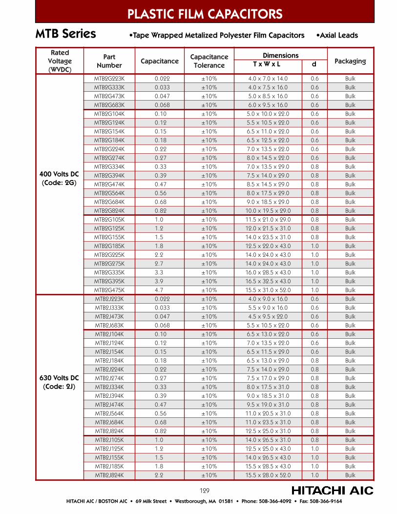
129
detaRegatloV)CDVW(
traPrebmuN
ecnaticapaCecnaticapaC
ecnareloTgnigakcaP
K322G2BTM 220.0 %01± 0.41x0.7x0.4 6.0 kluB
K333G2BTM 330.0 %01± 0.61x5.7x0.4 6.0 kluB
K374G2BTM 740.0 %01± 0.61x5.8x0.5 6.0 kluB
K386G2BTM 860.0 %01± 0.61x5.9x0.6 6.0 kluB
K401G2BTM 01.0 %01± 0.22x0.01x0.5 6.0 kluB
K421G2BTM 21.0 %01± 0.22x5.01x5.5 6.0 kluB
K451G2BTM 51.0 %01± 0.22x0.11x5.6 6.0 kluB
K481G2BTM 81.0 %01± 0.22x5.21x5.6 6.0 kluB
K422G2BTM 22.0 %01± 0.22x5.31x0.7 6.0 kluB
K472G2BTM 72.0 %01± 0.22x5.41x0.8 6.0 kluB
K433G2BTM 33.0 %01± 0.92x5.31x0.7 8.0 kluB
K493G2BTM 93.0 %01± 0.92x0.41x5.7 8.0 kluB
K474G2BTM 74.0 %01± 0.92x5.41x5.8 8.0 kluB
K465G2BTM 65.0 %01± 0.92x5.71x0.8 8.0 kluB
K486G2BTM 86.0 %01± 0.92x5.81x0.9 8.0 kluB
K428G2BTM 28.0 %01± 0.92x5.91x0.01 8.0 kluB
K501G2BTM 0.1 %01± 0.92x0.12x5.11 8.0 kluB
K521G2BTM 2.1 %01± 0.13x5.12x0.21 8.0 kluB
K551G2BTM 5.1 %01± 0.13x5.32x0.41 8.0 kluB
K581G2BTM 8.1 %01± 0.34x0.22x5.21 0.1 kluB
K522G2BTM 2.2 %01± 0.34x0.42x0.41 0.1 kluB
K572G2BTM 7.2 %01± 0.34x0.42x0.41 0.1 kluB
K533G2BTM 3.3 %01± 0.34x5.82x0.61 0.1 kluB
K593G2BTM 9.3 %01± 0.34x5.23x5.61 0.1 kluB
K574G2BTM 7.4 %01± 0.25x0.13x5.51 0.1 kluB
K322J2BTM 220.0 %01± 0.61x0.9x0.4 6.0 kluB
K333J2BTM 330.0 %01± 0.61x0.9x5.5 6.0 kluB
K374J2BTM 740.0 %01± 0.22x5.9x5.4 6.0 kluB
K386J2BTM 860.0 %01± 0.22x5.01x5.5 6.0 kluB
K401J2BTM 01.0 %01± 0.22x0.31x5.6 6.0 kluB
K421J2BTM 21.0 %01± 0.22x5.31x0.7 6.0 kluB
K451J2BTM 51.0 %01± 0.92x5.11x5.6 6.0 kluB
K481J2BTM 81.0 %01± 0.92x0.31x5.6 8.0 kluB
K422J2BTM 22.0 %01± 0.92x0.41x5.7 8.0 kluB
K472J2BTM 72.0 %01± 0.92x0.71x5.7 8.0 kluB
K433J2BTM 33.0 %01± 0.13x5.71x0.8 8.0 kluB
K493J2BTM 93.0 %01± 0.13x5.81x0.9 8.0 kluB
K474J2BTM 74.0 %01± 0.13x0.91x5.9 8.0 kluB
K465J2BTM 65.0 %01± 0.13x5.02x0.11 8.0 kluB
K486J2BTM 86.0 %01± 0.13x5.32x0.11 8.0 kluB
K428J2BTM 28.0 %01± 0.13x0.52x5.21 8.0 kluB
K501J2BTM 0.1 %01± 0.13x5.62x0.41 8.0 kluB
K521J2BTM 2.1 %01± 0.34x0.52x5.21 0.1 kluB
K551J2BTM 5.1 %01± 0.34x5.62x0.41 0.1 kluB
K581J2BTM 8.1 %01± 0.34x5.82x5.51 0.1 kluB
K428J2BTM 2.2 %01± 0.25x0.82x5.51 0.1 kluB
PLASTIC FILM CAPACITORS
AICHITACHI AIC / BOSTON AIC • 69 Milk Street • Westborough, MA 01581 • Phone: 508-366-4092 • Fax: 508-366-9164
MTB Series •Tape Wrapped Metalized Polyester Film Capacitors •Axial Leads
Dimensions T x W x L d
400 Volts DC(Code: 2G)
630 Volts DC(Code: 2J)
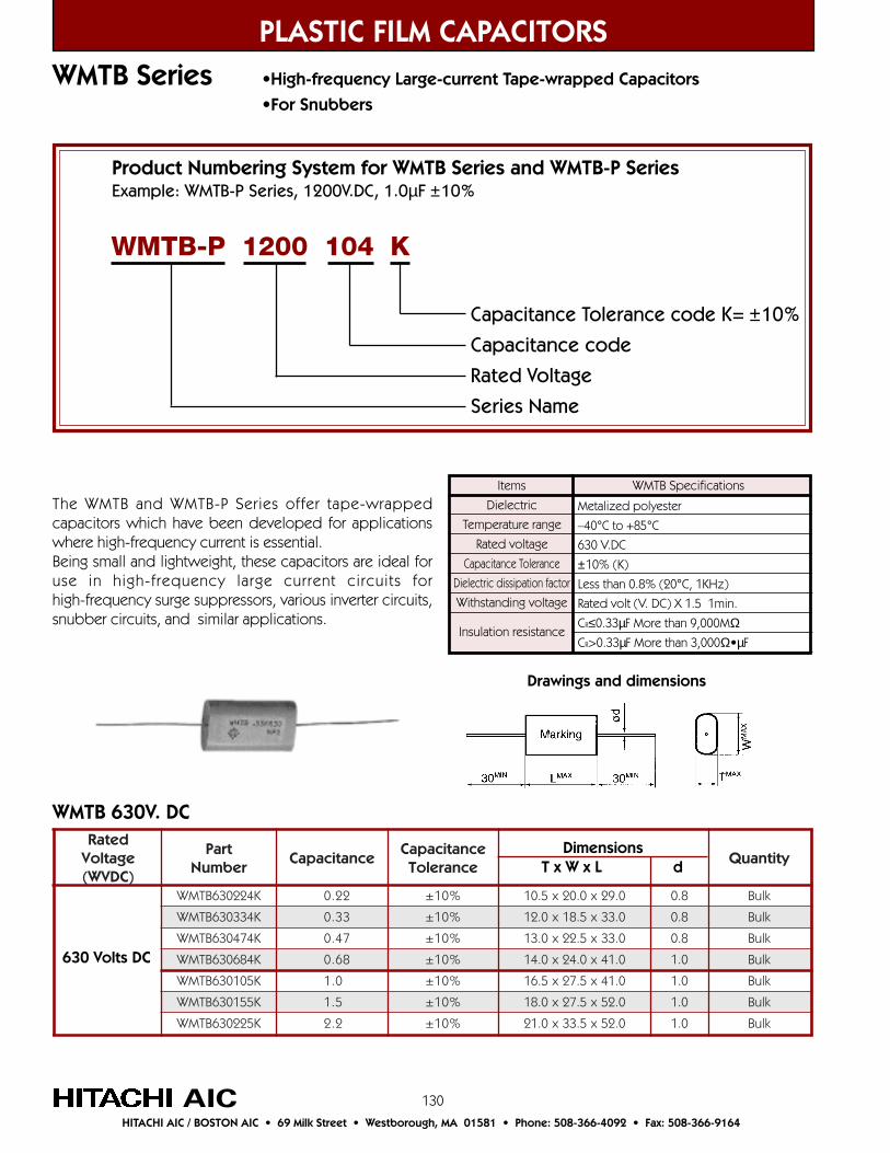
130
WMTB Series •High-frequency Large-current Tape-wrapped Capacitors
•For Snubbers
PLASTIC FILM CAPACITORS
AICHITACHI AIC / BOSTON AIC • 69 Milk Street • Westborough, MA 01581 • Phone: 508-366-4092 • Fax: 508-366-9164
Items
Dielectric
Temperature range
Rated voltage
Capacitance Tolerance
Dielectric dissipation factor
Withstanding voltage
Insulation resistance
Metalized polyester
–40°C to +85°C
630 V.DC
±10% (K)
Less than 0.8% (20°C, 1KHz)
Rated volt (V. DC) X 1.5 1min.
CR≤0.33µF More than 9,000MΩCR>0.33µF More than 3,000Ω•µF
WMTB Specifications
Product Numbering System for WMTB Series and WMTB-P SeriesExample: WMTB-P Series, 1200V.DC, 1.0µF ±10%
Capacitance Tolerance code K= ±10%
Capacitance code
Rated Voltage
Series Name
WMTB-P 1200 104 K
The WMTB and WMTB-P Series offer tape-wrappedcapacitors which have been developed for applicationswhere high-frequency current is essential.Being small and lightweight, these capacitors are ideal foruse in high-frequency large current circuits forhigh-frequency surge suppressors, various inverter circuits,snubber circuits, and similar applications.
Drawings and dimensions
detaRegatloV)CDVW(
traPrebmuN
ecnaticapaCecnaticapaC
ecnareloTytitnauQ
K422036BTMW 22.0 %01± 0.92x0.02x5.01 8.0 kluB
K433036BTMW 33.0 %01± 0.33x5.81x0.21 8.0 kluB
K474036BTMW 74.0 %01± 0.33x5.22x0.31 8.0 kluB
K486036BTMW 86.0 %01± 0.14x0.42x0.41 0.1 kluB
K501036BTMW 0.1 %01± 0.14x5.72x5.61 0.1 kluB
K551036BTMW 5.1 %01± 0.25x5.72x0.81 0.1 kluB
K522036BTMW 2.2 %01± 0.25x5.33x0.12 0.1 kluB
Dimensions T x W x L d
630 Volts DC
WMTB 630V. DC

131
PLASTIC FILM CAPACITORS
AICHITACHI AIC / BOSTON AIC • 69 Milk Street • Westborough, MA 01581 • Phone: 508-366-4092 • Fax: 508-366-9164
Items
Dielectric
Temperature range
Rated voltage
Capacitance Tolerance
Dielectric dissipation factor
Withstanding voltage
Insulation resistance
Metalized polypropylene
–40°C to +85°C
1200 V.DC
±10% (K)
Less than 0.1% (20°C, 1KHz)
Rated volt (V. DC) X 1.5 1min.
CR≤0.33µF More than 30,000MΩCR>0.33µF More than 10,000Ω•µF
WMTB-P Specifications
WMTB-P Series •High-frequency Large-current Tape-wrapped Capacitors
•For Snubbers
detaRegatloV)CDVW(
traPrebmuN
ecnaticapaCecnaticapaC
ecnareloTytitnauQ
K4010021P-BTMW 01.0 %01± 0.63x0.02x0.11 8.0 kluB
K4510021P-BTMW 51.0 %01± 0.63x0.32x5.31 8.0 kluB
K4220021P-BTMW 22.0 %01± 0.63x0.62x0.71 8.0 kluB
K4330021P-BTMW 33.0 %01± 0.14x0.52x5.51 0.1 kluB
K4740021P-BTMW 74.0 %01± 0.14x0.92x0.02 0.1 kluB
K4860021P-BTMW 86.0 %01± 0.14x0.33x5.32 0.1 kluB
K5010021P-BTMW 0.1 %01± 0.45x5.53x0.12 0.1 kluB
Dimensions T x W x L d
1200 Volts DC
WMTB-P 1200V. DC
Drawings and dimensions

132
FMDD-P Series •Resin Dipped, Metalized Polypropylene Film Capacitors
PLASTIC FILM CAPACITORS
AICHITACHI AIC / BOSTON AIC • 69 Milk Street • Westborough, MA 01581 • Phone: 508-366-4092 • Fax: 508-366-9164
Drawings and dimensions
The FMDD-P Series are resin dipped, metalizedpolypropylene film capacitors that are suitable for highfrequency and high voltage circuits. Applicationexamples include TV horizontal resonance, inverterlighting ballast circuits, resonance type SW powersupplies, etc.
Product Numbering System for FMDD-P Series.Example: FMDD-P Series, 1000V.DC, 0.01µF ±3%
Capacitance Tolerance code H= ±3%
Capacitance code
Rated Voltage
Series Name
FMDD-P 3A 103 H
• Metalized polypropylene film is used as a dielectric and forms a non-inductive winding for low loss.• Excellent temperature and frequency characteristics.• Excellent dielectric pulse voltage characteristics.• Exterior coating is flame retardant epoxy resin.
Items
Temperature range
Rated voltage
Capacitance Tolerance
Dielectric dissipation factor
Withstanding voltage
Insulation resistance(500V)
Others
–40°C to +105°C (with derating over 85°C)
1000V. DC (800Vp-p), 1250V. DC (1000Vp-p),
1600V. DC (1200Vp-p), 1800V. DC (1500Vp-p),
2000V. DC (1800Vp-p)
±3% (H), ±5% (J)
Less than 0.1% (20°C, 1KHz)
Between terminals Rated volt X 1.5, 1min.
Between terminal & outside coating Rated volt x 2.0, 1 to 5 sec.
Between terminals 30,000MΩ or more
Subject to EIAJ RC 2347 and JIS C 5102
Specifications
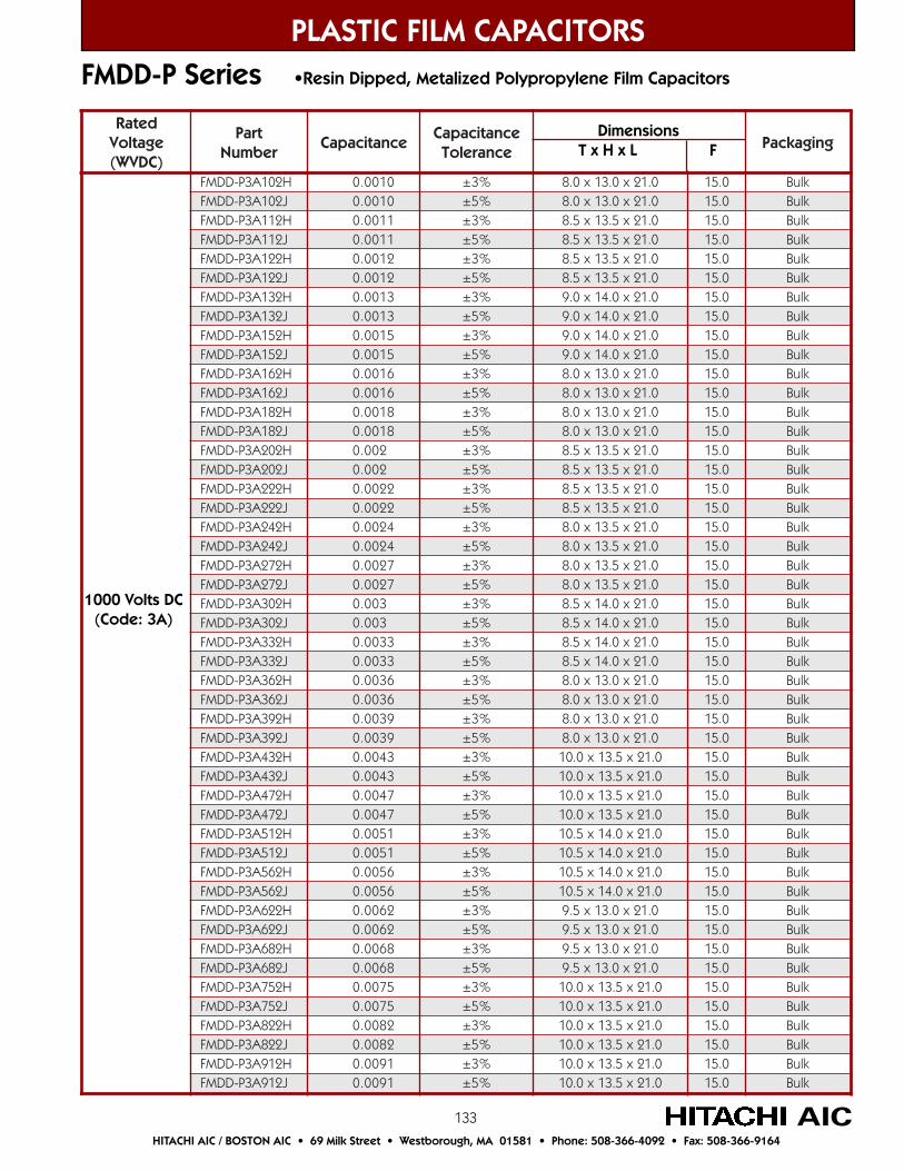
133
PLASTIC FILM CAPACITORS
AICHITACHI AIC / BOSTON AIC • 69 Milk Street • Westborough, MA 01581 • Phone: 508-366-4092 • Fax: 508-366-9164
FMDD-P Series •Resin Dipped, Metalized Polypropylene Film Capacitors
detaRegatloV)CDVW(
traPrebmuN
ecnaticapaCecnaticapaC
ecnareloTgnigakcaP
H201A3P-DDMF 0100.0 %3± 0.12x0.31x0.8 0.51 kluBJ201A3P-DDMF 0100.0 %5± 0.12x0.31x0.8 0.51 kluBH211A3P-DDMF 1100.0 %3± 0.12x5.31x5.8 0.51 kluBJ211A3P-DDMF 1100.0 %5± 0.12x5.31x5.8 0.51 kluBH221A3P-DDMF 2100.0 %3± 0.12x5.31x5.8 0.51 kluBJ221A3P-DDMF 2100.0 %5± 0.12x5.31x5.8 0.51 kluBH231A3P-DDMF 3100.0 %3± 0.12x0.41x0.9 0.51 kluBJ231A3P-DDMF 3100.0 %5± 0.12x0.41x0.9 0.51 kluBH251A3P-DDMF 5100.0 %3± 0.12x0.41x0.9 0.51 kluBJ251A3P-DDMF 5100.0 %5± 0.12x0.41x0.9 0.51 kluBH261A3P-DDMF 6100.0 %3± 0.12x0.31x0.8 0.51 kluBJ261A3P-DDMF 6100.0 %5± 0.12x0.31x0.8 0.51 kluBH281A3P-DDMF 8100.0 %3± 0.12x0.31x0.8 0.51 kluBJ281A3P-DDMF 8100.0 %5± 0.12x0.31x0.8 0.51 kluBH202A3P-DDMF 200.0 %3± 0.12x5.31x5.8 0.51 kluBJ202A3P-DDMF 200.0 %5± 0.12x5.31x5.8 0.51 kluBH222A3P-DDMF 2200.0 %3± 0.12x5.31x5.8 0.51 kluBJ222A3P-DDMF 2200.0 %5± 0.12x5.31x5.8 0.51 kluBH242A3P-DDMF 4200.0 %3± 0.12x5.31x0.8 0.51 kluBJ242A3P-DDMF 4200.0 %5± 0.12x5.31x0.8 0.51 kluBH272A3P-DDMF 7200.0 %3± 0.12x5.31x0.8 0.51 kluBJ272A3P-DDMF 7200.0 %5± 0.12x5.31x0.8 0.51 kluBH203A3P-DDMF 300.0 %3± 0.12x0.41x5.8 0.51 kluBJ203A3P-DDMF 300.0 %5± 0.12x0.41x5.8 0.51 kluBH233A3P-DDMF 3300.0 %3± 0.12x0.41x5.8 0.51 kluBJ233A3P-DDMF 3300.0 %5± 0.12x0.41x5.8 0.51 kluBH263A3P-DDMF 6300.0 %3± 0.12x0.31x0.8 0.51 kluBJ263A3P-DDMF 6300.0 %5± 0.12x0.31x0.8 0.51 kluBH293A3P-DDMF 9300.0 %3± 0.12x0.31x0.8 0.51 kluBJ293A3P-DDMF 9300.0 %5± 0.12x0.31x0.8 0.51 kluBH234A3P-DDMF 3400.0 %3± 0.12x5.31x0.01 0.51 kluBJ234A3P-DDMF 3400.0 %5± 0.12x5.31x0.01 0.51 kluBH274A3P-DDMF 7400.0 %3± 0.12x5.31x0.01 0.51 kluBJ274A3P-DDMF 7400.0 %5± 0.12x5.31x0.01 0.51 kluBH215A3P-DDMF 1500.0 %3± 0.12x0.41x5.01 0.51 kluBJ215A3P-DDMF 1500.0 %5± 0.12x0.41x5.01 0.51 kluBH265A3P-DDMF 6500.0 %3± 0.12x0.41x5.01 0.51 kluBJ265A3P-DDMF 6500.0 %5± 0.12x0.41x5.01 0.51 kluBH226A3P-DDMF 2600.0 %3± 0.12x0.31x5.9 0.51 kluBJ226A3P-DDMF 2600.0 %5± 0.12x0.31x5.9 0.51 kluBH286A3P-DDMF 8600.0 %3± 0.12x0.31x5.9 0.51 kluBJ286A3P-DDMF 8600.0 %5± 0.12x0.31x5.9 0.51 kluBH257A3P-DDMF 5700.0 %3± 0.12x5.31x0.01 0.51 kluBJ257A3P-DDMF 5700.0 %5± 0.12x5.31x0.01 0.51 kluBH228A3P-DDMF 2800.0 %3± 0.12x5.31x0.01 0.51 kluBJ228A3P-DDMF 2800.0 %5± 0.12x5.31x0.01 0.51 kluBH219A3P-DDMF 1900.0 %3± 0.12x5.31x0.01 0.51 kluBJ219A3P-DDMF 1900.0 %5± 0.12x5.31x0.01 0.51 kluB
Dimensions T x H x L F
1000 Volts DC(Code: 3A)
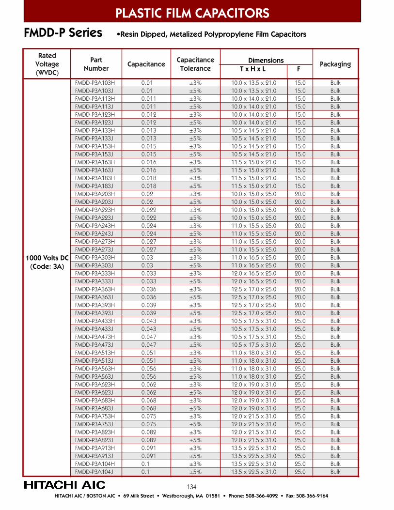
134
FMDD-P Series •Resin Dipped, Metalized Polypropylene Film Capacitors
PLASTIC FILM CAPACITORS
AICHITACHI AIC / BOSTON AIC • 69 Milk Street • Westborough, MA 01581 • Phone: 508-366-4092 • Fax: 508-366-9164
detaRegatloV)CDVW(
traPrebmuN
ecnaticapaCecnaticapaC
ecnareloTgnigakcaP
H301A3P-DDMF 10.0 %3± 0.12x5.31x0.01 0.51 kluBJ301A3P-DDMF 10.0 %5± 0.12x5.31x0.01 0.51 kluBH311A3P-DDMF 110.0 %3± 0.12x0.41x0.01 0.51 kluBJ311A3P-DDMF 110.0 %5± 0.12x0.41x0.01 0.51 kluBH321A3P-DDMF 210.0 %3± 0.12x0.41x0.01 0.51 kluBJ321A3P-DDMF 210.0 %5± 0.12x0.41x0.01 0.51 kluBH331A3P-DDMF 310.0 %3± 0.12x5.41x5.01 0.51 kluBJ331A3P-DDMF 310.0 %5± 0.12x5.41x5.01 0.51 kluBH351A3P-DDMF 510.0 %3± 0.12x5.41x5.01 0.51 kluBJ351A3P-DDMF 510.0 %5± 0.12x5.41x5.01 0.51 kluBH361A3P-DDMF 610.0 %3± 0.12x0.51x5.11 0.51 kluBJ361A3P-DDMF 610.0 %5± 0.12x0.51x5.11 0.51 kluBH381A3P-DDMF 810.0 %3± 0.12x0.51x5.11 0.51 kluBJ381A3P-DDMF 810.0 %5± 0.12x0.51x5.11 0.51 kluBH302A3P-DDMF 20.0 %3± 0.52x0.51x0.01 0.02 kluBJ302A3P-DDMF 20.0 %5± 0.52x0.51x0.01 0.02 kluBH322A3P-DDMF 220.0 %3± 0.52x0.51x0.01 0.02 kluBJ322A3P-DDMF 220.0 %5± 0.52x0.51x0.01 0.02 kluBH342A3P-DDMF 420.0 %3± 0.52x5.51x0.11 0.02 kluBJ342A3P-DDMF 420.0 %5± 0.52x5.51x0.11 0.02 kluBH372A3P-DDMF 720.0 %3± 0.52x5.51x0.11 0.02 kluBJ372A3P-DDMF 720.0 %5± 0.52x5.51x0.11 0.02 kluBH303A3P-DDMF 30.0 %3± 0.52x5.61x0.11 0.02 kluBJ303A3P-DDMF 30.0 %5± 0.52x5.61x0.11 0.02 kluBH333A3P-DDMF 330.0 %3± 0.52x5.61x0.21 0.02 kluBJ333A3P-DDMF 330.0 %5± 0.52x5.61x0.21 0.02 kluBH363A3P-DDMF 630.0 %3± 0.52x0.71x5.21 0.02 kluBJ363A3P-DDMF 630.0 %5± 0.52x0.71x5.21 0.02 kluBH393A3P-DDMF 930.0 %3± 0.52x0.71x5.21 0.02 kluBJ393A3P-DDMF 930.0 %5± 0.52x0.71x5.21 0.02 kluBH334A3P-DDMF 340.0 %3± 0.13x5.71x5.01 0.52 kluBJ334A3P-DDMF 340.0 %5± 0.13x5.71x5.01 0.52 kluBH374A3P-DDMF 740.0 %3± 0.13x5.71x5.01 0.52 kluBJ374A3P-DDMF 740.0 %5± 0.13x5.71x5.01 0.52 kluBH315A3P-DDMF 150.0 %3± 0.13x0.81x0.11 0.52 kluBJ315A3P-DDMF 150.0 %5± 0.13x0.81x0.11 0.52 kluBH365A3P-DDMF 650.0 %3± 0.13x0.81x0.11 0.52 kluBJ365A3P-DDMF 650.0 %5± 0.13x0.81x0.11 0.52 kluBH326A3P-DDMF 260.0 %3± 0.13x0.91x0.21 0.52 kluBJ326A3P-DDMF 260.0 %5± 0.13x0.91x0.21 0.52 kluBH386A3P-DDMF 860.0 %3± 0.13x0.91x0.21 0.52 kluBJ386A3P-DDMF 860.0 %5± 0.13x0.91x0.21 0.52 kluBH357A3P-DDMF 570.0 %3± 0.13x5.12x0.21 0.52 kluBJ357A3P-DDMF 570.0 %5± 0.13x5.12x0.21 0.52 kluBH328A3P-DDMF 280.0 %3± 0.13x5.12x0.21 0.52 kluBJ328A3P-DDMF 280.0 %5± 0.13x5.12x0.21 0.52 kluBH319A3P-DDMF 190.0 %3± 0.13x5.22x5.31 0.52 kluBJ319A3P-DDMF 190.0 %5± 0.13x5.22x5.31 0.52 kluBH401A3P-DDMF 1.0 %3± 0.13x5.22x5.31 0.52 kluBJ401A3P-DDMF 1.0 %5± 0.13x5.22x5.31 0.52 kluB
1000 Volts DC(Code: 3A)
Dimensions T x H x L F

135
detaRegatloV)CDVW(
traPrebmuN
ecnaticapaCecnaticapaC
ecnareloTgnigakcaP
H201B3P-DDMF 0100.0 %3± 5.32x5.21x5.7 0.02 kluBJ201B3P-DDMF 0100.0 %5± 5.32x5.21x5.7 0.02 kluBH211B3P-DDMF 1100.0 %3± 5.32x5.21x0.8 0.02 kluBJ211B3P-DDMF 1100.0 %5± 5.32x5.21x0.8 0.02 kluBH221B3P-DDMF 2100.0 %3± 5.32x5.21x0.8 0.02 kluBJ221B3P-DDMF 2100.0 %5± 5.32x5.21x0.8 0.02 kluBH231B3P-DDMF 3100.0 %3± 5.32x5.21x5.7 0.02 kluBJ231B3P-DDMF 3100.0 %5± 5.32x5.21x5.7 0.02 kluBH251B3P-DDMF 5100.0 %3± 5.32x5.21x5.7 0.02 kluBJ251B3P-DDMF 5100.0 %5± 5.32x5.21x5.7 0.02 kluBH261B3P-DDMF 6100.0 %3± 5.32x0.31x0.8 0.02 kluBJ261B3P-DDMF 6100.0 %5± 5.32x0.31x0.8 0.02 kluBH281B3P-DDMF 8100.0 %3± 5.32x0.31x0.8 0.02 kluBJ281B3P-DDMF 8100.0 %5± 5.32x0.31x0.8 0.02 kluBH202B3P-DDMF 200.0 %3± 5.32x5.31x5.8 0.02 kluBJ202B3P-DDMF 200.0 %5± 5.32x5.31x5.8 0.02 kluBH222B3P-DDMF 2200.0 %3± 5.32x5.31x5.8 0.02 kluBJ222B3P-DDMF 2200.0 %5± 5.32x5.31x5.8 0.02 kluBH242B3P-DDMF 4200.0 %3± 5.32x0.31x5.8 0.02 kluBJ242B3P-DDMF 4200.0 %5± 5.32x0.31x5.8 0.02 kluBH272B3P-DDMF 7200.0 %3± 5.32x0.31x5.8 0.02 kluBJ272B3P-DDMF 7200.0 %5± 5.32x0.31x5.8 0.02 kluBH203B3P-DDMF 300.0 %3± 5.32x5.31x0.9 0.02 kluBJ203B3P-DDMF 300.0 %5± 5.32x5.31x0.9 0.02 kluBH233B3P-DDMF 3300.0 %3± 5.32x5.31x0.9 0.02 kluBJ233B3P-DDMF 3300.0 %5± 5.32x5.31x0.9 0.02 kluBH263B3P-DDMF 6300.0 %3± 5.32x0.41x5.9 0.02 kluBJ263B3P-DDMF 6300.0 %5± 5.32x0.41x5.9 0.02 kluBH293B3P-DDMF 9300.0 %3± 5.32x0.41x5.9 0.02 kluBJ293B3P-DDMF 9300.0 %5± 5.32x0.41x5.9 0.02 kluBH234B3P-DDMF 3400.0 %3± 0.42x0.51x0.01 0.02 kluBJ234B3P-DDMF 3400.0 %5± 0.42x0.51x0.01 0.02 kluBH274B3P-DDMF 7400.0 %3± 0.42x0.51x0.01 0.02 kluBJ274B3P-DDMF 7400.0 %5± 0.42x0.51x0.01 0.02 kluBH215B3P-DDMF 1500.0 %3± 0.42x0.61x5.01 0.02 kluBJ215B3P-DDMF 1500.0 %5± 0.42x0.61x5.01 0.02 kluBH265B3P-DDMF 6500.0 %3± 0.42x0.61x5.01 0.02 kluBJ265B3P-DDMF 6500.0 %5± 0.42x0.61x5.01 0.02 kluBH226B3P-DDMF 2600.0 %3± 0.42x5.51x5.8 0.02 kluBJ226B3P-DDMF 2600.0 %5± 0.42x5.51x5.8 0.02 kluBH286B3P-DDMF 8600.0 %3± 0.42x5.51x5.8 0.02 kluBJ286B3P-DDMF 8600.0 %5± 0.42x5.51x5.8 0.02 kluBH257B3P-DDMF 5700.0 %3± 0.42x0.61x0.9 0.02 kluBJ257B3P-DDMF 5700.0 %5± 0.42x0.61x0.9 0.02 kluBH228B3P-DDMF 2800.0 %3± 0.42x0.61x0.9 0.02 kluBJ228B3P-DDMF 2800.0 %5± 0.42x0.61x0.9 0.02 kluBH219B3P-DDMF 1900.0 %3± 0.42x5.61x0.01 0.02 kluBJ219B3P-DDMF 1900.0 %5± 0.42x5.61x0.01 0.02 kluB
PLASTIC FILM CAPACITORS
AICHITACHI AIC / BOSTON AIC • 69 Milk Street • Westborough, MA 01581 • Phone: 508-366-4092 • Fax: 508-366-9164
FMDD-P Series •Resin Dipped, Metalized Polypropylene Film Capacitors
Dimensions T x H x L F
1250 Volts DC(Code: 3B)
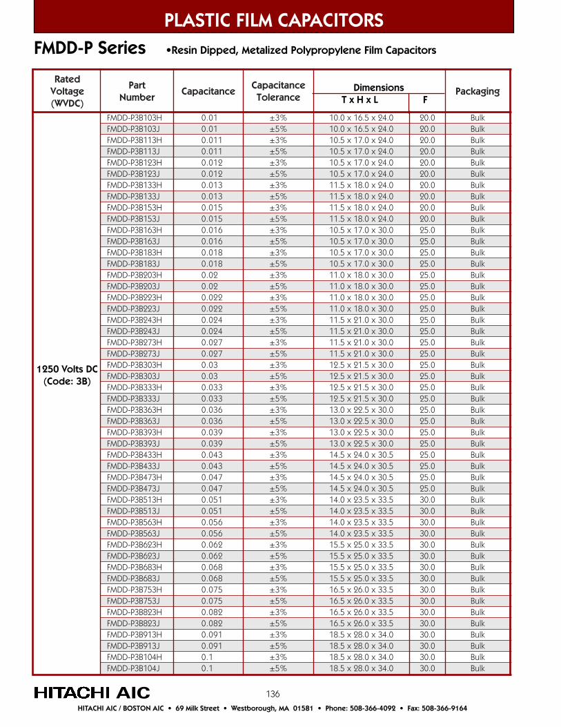
136
detaRegatloV)CDVW(
traPrebmuN
ecnaticapaCecnaticapaC
ecnareloTgnigakcaP
H301B3P-DDMF 10.0 %3± 0.42x5.61x0.01 0.02 kluBJ301B3P-DDMF 10.0 %5± 0.42x5.61x0.01 0.02 kluBH311B3P-DDMF 110.0 %3± 0.42x0.71x5.01 0.02 kluBJ311B3P-DDMF 110.0 %5± 0.42x0.71x5.01 0.02 kluBH321B3P-DDMF 210.0 %3± 0.42x0.71x5.01 0.02 kluBJ321B3P-DDMF 210.0 %5± 0.42x0.71x5.01 0.02 kluBH331B3P-DDMF 310.0 %3± 0.42x0.81x5.11 0.02 kluBJ331B3P-DDMF 310.0 %5± 0.42x0.81x5.11 0.02 kluBH351B3P-DDMF 510.0 %3± 0.42x0.81x5.11 0.02 kluBJ351B3P-DDMF 510.0 %5± 0.42x0.81x5.11 0.02 kluBH361B3P-DDMF 610.0 %3± 0.03x0.71x5.01 0.52 kluBJ361B3P-DDMF 610.0 %5± 0.03x0.71x5.01 0.52 kluBH381B3P-DDMF 810.0 %3± 0.03x0.71x5.01 0.52 kluBJ381B3P-DDMF 810.0 %5± 0.03x0.71x5.01 0.52 kluBH302B3P-DDMF 20.0 %3± 0.03x0.81x0.11 0.52 kluBJ302B3P-DDMF 20.0 %5± 0.03x0.81x0.11 0.52 kluBH322B3P-DDMF 220.0 %3± 0.03x0.81x0.11 0.52 kluBJ322B3P-DDMF 220.0 %5± 0.03x0.81x0.11 0.52 kluBH342B3P-DDMF 420.0 %3± 0.03x0.12x5.11 0.52 kluBJ342B3P-DDMF 420.0 %5± 0.03x0.12x5.11 0.52 kluBH372B3P-DDMF 720.0 %3± 0.03x0.12x5.11 0.52 kluBJ372B3P-DDMF 720.0 %5± 0.03x0.12x5.11 0.52 kluBH303B3P-DDMF 30.0 %3± 0.03x5.12x5.21 0.52 kluBJ303B3P-DDMF 30.0 %5± 0.03x5.12x5.21 0.52 kluBH333B3P-DDMF 330.0 %3± 0.03x5.12x5.21 0.52 kluBJ333B3P-DDMF 330.0 %5± 0.03x5.12x5.21 0.52 kluBH363B3P-DDMF 630.0 %3± 0.03x5.22x0.31 0.52 kluBJ363B3P-DDMF 630.0 %5± 0.03x5.22x0.31 0.52 kluBH393B3P-DDMF 930.0 %3± 0.03x5.22x0.31 0.52 kluBJ393B3P-DDMF 930.0 %5± 0.03x5.22x0.31 0.52 kluBH334B3P-DDMF 340.0 %3± 5.03x0.42x5.41 0.52 kluBJ334B3P-DDMF 340.0 %5± 5.03x0.42x5.41 0.52 kluBH374B3P-DDMF 740.0 %3± 5.03x0.42x5.41 0.52 kluBJ374B3P-DDMF 740.0 %5± 5.03x0.42x5.41 0.52 kluBH315B3P-DDMF 150.0 %3± 5.33x5.32x0.41 0.03 kluBJ315B3P-DDMF 150.0 %5± 5.33x5.32x0.41 0.03 kluBH365B3P-DDMF 650.0 %3± 5.33x5.32x0.41 0.03 kluBJ365B3P-DDMF 650.0 %5± 5.33x5.32x0.41 0.03 kluBH326B3P-DDMF 260.0 %3± 5.33x0.52x5.51 0.03 kluBJ326B3P-DDMF 260.0 %5± 5.33x0.52x5.51 0.03 kluBH386B3P-DDMF 860.0 %3± 5.33x0.52x5.51 0.03 kluBJ386B3P-DDMF 860.0 %5± 5.33x0.52x5.51 0.03 kluBH357B3P-DDMF 570.0 %3± 5.33x0.62x5.61 0.03 kluBJ357B3P-DDMF 570.0 %5± 5.33x0.62x5.61 0.03 kluBH328B3P-DDMF 280.0 %3± 5.33x0.62x5.61 0.03 kluBJ328B3P-DDMF 280.0 %5± 5.33x0.62x5.61 0.03 kluBH319B3P-DDMF 190.0 %3± 0.43x0.82x5.81 0.03 kluBJ319B3P-DDMF 190.0 %5± 0.43x0.82x5.81 0.03 kluBH401B3P-DDMF 1.0 %3± 0.43x0.82x5.81 0.03 kluBJ401B3P-DDMF 1.0 %5± 0.43x0.82x5.81 0.03 kluB
FMDD-P Series •Resin Dipped, Metalized Polypropylene Film Capacitors
PLASTIC FILM CAPACITORS
AICHITACHI AIC / BOSTON AIC • 69 Milk Street • Westborough, MA 01581 • Phone: 508-366-4092 • Fax: 508-366-9164
1250 Volts DC(Code: 3B)
Dimensions T x H x L F
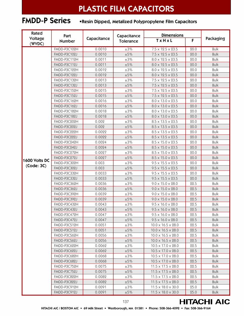
137
detaRegatloV)CDVW(
traPrebmuN
ecnaticapaCecnaticapaC
ecnareloTgnigakcaP
H201C3P-DDMF 0100.0 %3± 5.32x5.21x5.7 0.02 kluBJ201C3P-DDMF 0100.0 %5± 5.32x5.21x5.7 0.02 kluBH211C3P-DDMF 1100.0 %3± 5.32x5.21x0.8 0.02 kluBJ211C3P-DDMF 1100.0 %5± 5.32x5.21x0.8 0.02 kluBH221C3P-DDMF 2100.0 %3± 5.32x5.21x0.8 0.02 kluBJ221C3P-DDMF 2100.0 %5± 5.32x5.21x0.8 0.02 kluBH231C3P-DDMF 3100.0 %3± 5.32x5.21x5.7 0.02 kluBJ231C3P-DDMF 3100.0 %5± 5.32x5.21x5.7 0.02 kluBH251C3P-DDMF 5100.0 %3± 5.32x5.21x5.7 0.02 kluBJ251C3P-DDMF 5100.0 %5± 5.32x5.21x5.7 0.02 kluBH261C3P-DDMF 6100.0 %3± 5.32x0.31x0.8 0.02 kluBJ261C3P-DDMF 6100.0 %5± 5.32x0.31x0.8 0.02 kluBH281C3P-DDMF 8100.0 %3± 5.32x0.31x0.8 0.02 kluBJ281C3P-DDMF 8100.0 %5± 5.32x0.31x0.8 0.02 kluBH202C3P-DDMF 200.0 %3± 5.32x5.31x5.8 0.02 kluBJ202C3P-DDMF 200.0 %5± 5.32x5.31x5.8 0.02 kluBH222C3P-DDMF 2200.0 %3± 5.32x5.31x5.8 0.02 kluBJ222C3P-DDMF 2200.0 %5± 5.32x5.31x5.8 0.02 kluBH242C3P-DDMF 4200.0 %3± 5.32x0.51x5.8 0.02 kluBJ242C3P-DDMF 4200.0 %5± 5.32x0.51x5.8 0.02 kluBH272C3P-DDMF 7200.0 %3± 5.32x0.51x5.8 0.02 kluBJ272C3P-DDMF 7200.0 %5± 5.32x0.51x5.8 0.02 kluBH203C3P-DDMF 300.0 %3± 5.32x5.51x5.9 0.02 kluBJ203C3P-DDMF 300.0 %5± 5.32x5.51x5.9 0.02 kluBH233C3P-DDMF 3300.0 %3± 5.32x5.51x5.9 0.02 kluBJ233C3P-DDMF 3300.0 %5± 5.32x5.51x5.9 0.02 kluBH263C3P-DDMF 6300.0 %3± 0.82x0.51x0.9 5.22 kluBJ263C3P-DDMF 6300.0 %5± 0.82x0.51x0.9 5.22 kluBH293C3P-DDMF 9300.0 %3± 0.82x0.51x0.9 5.22 kluBJ293C3P-DDMF 9300.0 %5± 0.82x0.51x0.9 5.22 kluBH234C3P-DDMF 3400.0 %3± 0.82x0.61x5.9 5.22 kluBJ234C3P-DDMF 3400.0 %5± 0.82x0.61x5.9 5.22 kluBH274C3P-DDMF 7400.0 %3± 0.82x0.61x5.9 5.22 kluBJ274C3P-DDMF 7400.0 %5± 0.82x0.61x5.9 5.22 kluBH215C3P-DDMF 1500.0 %3± 0.82x5.61x0.01 5.22 kluBJ215C3P-DDMF 1500.0 %5± 0.82x5.61x0.01 5.22 kluBH265C3P-DDMF 6500.0 %3± 0.82x5.61x0.01 5.22 kluBJ265C3P-DDMF 6500.0 %5± 0.82x5.61x0.01 5.22 kluBH226C3P-DDMF 2600.0 %3± 0.82x0.71x5.01 5.22 kluBJ226C3P-DDMF 2600.0 %5± 0.82x0.71x5.01 5.22 kluBH286C3P-DDMF 8600.0 %3± 0.82x0.71x5.01 5.22 kluBJ286C3P-DDMF 8600.0 %5± 0.82x0.71x5.01 5.22 kluBH257C3P-DDMF 5700.0 %3± 0.82x5.71x5.11 5.22 kluBJ257C3P-DDMF 5700.0 %5± 0.82x5.71x5.11 5.22 kluBH228C3P-DDMF 2800.0 %3± 0.82x5.71x5.11 5.22 kluBJ228C3P-DDMF 2800.0 %5± 0.82x5.71x5.11 5.22 kluBH219C3P-DDMF 1900.0 %3± 0.03x0.81x5.11 0.52 kluBJ219C3P-DDMF 1900.0 %5± 0.03x0.81x5.11 0.52 kluB
PLASTIC FILM CAPACITORS
AICHITACHI AIC / BOSTON AIC • 69 Milk Street • Westborough, MA 01581 • Phone: 508-366-4092 • Fax: 508-366-9164
FMDD-P Series •Resin Dipped, Metalized Polypropylene Film Capacitors
Dimensions T x H x L F
1600 Volts DC(Code: 3C)
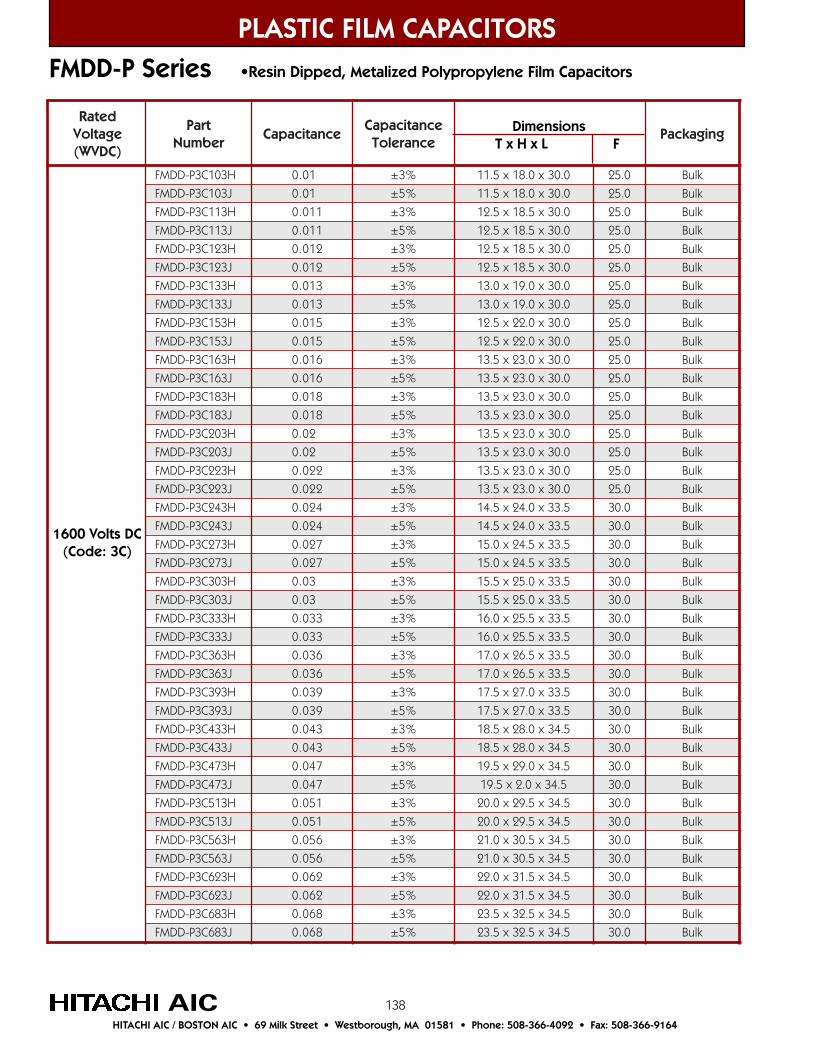
138
FMDD-P Series •Resin Dipped, Metalized Polypropylene Film Capacitors
PLASTIC FILM CAPACITORS
AICHITACHI AIC / BOSTON AIC • 69 Milk Street • Westborough, MA 01581 • Phone: 508-366-4092 • Fax: 508-366-9164
1600 Volts DC(Code: 3C)
Dimensions T x H x L F
detaRegatloV)CDVW(
traPrebmuN
ecnaticapaCecnaticapaC
ecnareloTgnigakcaP
H301C3P-DDMF 10.0 %3± 0.03x0.81x5.11 0.52 kluB
J301C3P-DDMF 10.0 %5± 0.03x0.81x5.11 0.52 kluB
H311C3P-DDMF 110.0 %3± 0.03x5.81x5.21 0.52 kluB
J311C3P-DDMF 110.0 %5± 0.03x5.81x5.21 0.52 kluB
H321C3P-DDMF 210.0 %3± 0.03x5.81x5.21 0.52 kluB
J321C3P-DDMF 210.0 %5± 0.03x5.81x5.21 0.52 kluB
H331C3P-DDMF 310.0 %3± 0.03x0.91x0.31 0.52 kluB
J331C3P-DDMF 310.0 %5± 0.03x0.91x0.31 0.52 kluB
H351C3P-DDMF 510.0 %3± 0.03x0.22x5.21 0.52 kluB
J351C3P-DDMF 510.0 %5± 0.03x0.22x5.21 0.52 kluB
H361C3P-DDMF 610.0 %3± 0.03x0.32x5.31 0.52 kluB
J361C3P-DDMF 610.0 %5± 0.03x0.32x5.31 0.52 kluB
H381C3P-DDMF 810.0 %3± 0.03x0.32x5.31 0.52 kluB
J381C3P-DDMF 810.0 %5± 0.03x0.32x5.31 0.52 kluB
H302C3P-DDMF 20.0 %3± 0.03x0.32x5.31 0.52 kluB
J302C3P-DDMF 20.0 %5± 0.03x0.32x5.31 0.52 kluB
H322C3P-DDMF 220.0 %3± 0.03x0.32x5.31 0.52 kluB
J322C3P-DDMF 220.0 %5± 0.03x0.32x5.31 0.52 kluB
H342C3P-DDMF 420.0 %3± 5.33x0.42x5.41 0.03 kluB
J342C3P-DDMF 420.0 %5± 5.33x0.42x5.41 0.03 kluB
H372C3P-DDMF 720.0 %3± 5.33x5.42x0.51 0.03 kluB
J372C3P-DDMF 720.0 %5± 5.33x5.42x0.51 0.03 kluB
H303C3P-DDMF 30.0 %3± 5.33x0.52x5.51 0.03 kluB
J303C3P-DDMF 30.0 %5± 5.33x0.52x5.51 0.03 kluB
H333C3P-DDMF 330.0 %3± 5.33x5.52x0.61 0.03 kluB
J333C3P-DDMF 330.0 %5± 5.33x5.52x0.61 0.03 kluB
H363C3P-DDMF 630.0 %3± 5.33x5.62x0.71 0.03 kluB
J363C3P-DDMF 630.0 %5± 5.33x5.62x0.71 0.03 kluB
H393C3P-DDMF 930.0 %3± 5.33x0.72x5.71 0.03 kluB
J393C3P-DDMF 930.0 %5± 5.33x0.72x5.71 0.03 kluB
H334C3P-DDMF 340.0 %3± 5.43x0.82x5.81 0.03 kluB
J334C3P-DDMF 340.0 %5± 5.43x0.82x5.81 0.03 kluB
H374C3P-DDMF 740.0 %3± 5.43x0.92x5.91 0.03 kluB
J374C3P-DDMF 740.0 %5± 5.43x0.2x5.91 0.03 kluB
H315C3P-DDMF 150.0 %3± 5.43x5.92x0.02 0.03 kluB
J315C3P-DDMF 150.0 %5± 5.43x5.92x0.02 0.03 kluB
H365C3P-DDMF 650.0 %3± 5.43x5.03x0.12 0.03 kluB
J365C3P-DDMF 650.0 %5± 5.43x5.03x0.12 0.03 kluB
H326C3P-DDMF 260.0 %3± 5.43x5.13x0.22 0.03 kluB
J326C3P-DDMF 260.0 %5± 5.43x5.13x0.22 0.03 kluB
H386C3P-DDMF 860.0 %3± 5.43x5.23x5.32 0.03 kluB
J386C3P-DDMF 860.0 %5± 5.43x5.23x5.32 0.03 kluB

139
detaRegatloV)CDVW(
traPrebmuN
ecnaticapaCecnaticapaC
ecnareloTgnigakcaP
H201Q3P-DDMF 0100.0 %3± 5.72x0.21x5.7 5.22 kluBJ201Q3P-DDMF 0100.0 %5± 5.72x0.21x5.7 5.22 kluBH211Q3P-DDMF 1100.0 %3± 5.72x5.21x5.7 5.22 kluBJ211Q3P-DDMF 1100.0 %5± 5.72x5.21x5.7 5.22 kluBH221Q3P-DDMF 2100.0 %3± 5.72x5.21x5.7 5.22 kluBJ221Q3P-DDMF 2100.0 %5± 5.72x5.21x5.7 5.22 kluBH231Q3P-DDMF 3100.0 %3± 5.72x0.31x5.8 5.22 kluBJ231Q3P-DDMF 3100.0 %5± 5.72x0.31x5.8 5.22 kluBH251Q3P-DDMF 5100.0 %3± 5.72x0.31x5.8 5.22 kluBJ251Q3P-DDMF 5100.0 %5± 5.72x0.31x5.8 5.22 kluBH261Q3P-DDMF 6100.0 %3± 5.72x5.41x5.8 5.22 kluBJ261Q3P-DDMF 6100.0 %5± 5.72x5.41x5.8 5.22 kluBH281Q3P-DDMF 8100.0 %3± 5.72x5.41x5.8 5.22 kluBJ281Q3P-DDMF 8100.0 %5± 5.72x5.41x5.8 5.22 kluBH202Q3P-DDMF 200.0 %3± 5.72x0.51x0.9 5.22 kluBJ202Q3P-DDMF 200.0 %5± 5.72x0.51x0.9 5.22 kluBH222Q3P-DDMF 2200.0 %3± 5.72x0.51x0.9 5.22 kluBJ222Q3P-DDMF 2200.0 %5± 5.72x0.51x0.9 5.22 kluBH242Q3P-DDMF 4200.0 %3± 5.72x0.61x5.9 5.22 kluBJ242Q3P-DDMF 4200.0 %5± 5.72x0.61x5.9 5.22 kluBH272Q3P-DDMF 7200.0 %3± 5.72x0.61x5.9 5.22 kluBJ272Q3P-DDMF 7200.0 %5± 5.72x0.61x5.9 5.22 kluBH203Q3P-DDMF 300.0 %3± 5.72x5.61x0.01 5.22 kluBJ203Q3P-DDMF 300.0 %5± 5.72x5.61x0.01 5.22 kluBH233Q3P-DDMF 3300.0 %3± 5.72x5.61x0.01 5.22 kluBJ233Q3P-DDMF 3300.0 %5± 5.72x5.61x0.01 5.22 kluBH263Q3P-DDMF 6300.0 %3± 0.92x5.51x0.9 0.52 kluBJ263Q3P-DDMF 6300.0 %5± 0.92x5.51x0.9 0.52 kluBH293Q3P-DDMF 9300.0 %3± 0.92x5.51x0.9 0.52 kluBJ293Q3P-DDMF 9300.0 %5± 0.92x5.51x0.9 0.52 kluBH234Q3P-DDMF 3400.0 %3± 0.92x0.61x5.9 0.52 kluBJ234Q3P-DDMF 3400.0 %5± 0.92x0.61x5.9 0.52 kluBH274Q3P-DDMF 7400.0 %3± 0.92x0.61x5.9 0.52 kluBJ274Q3P-DDMF 7400.0 %5± 0.92x0.61x5.9 0.52 kluBH215Q3P-DDMF 1500.0 %3± 0.92x5.61x0.01 0.52 kluBJ215Q3P-DDMF 1500.0 %5± 0.92x5.61x0.01 0.52 kluBH265Q3P-DDMF 6500.0 %3± 0.92x5.61x0.01 0.52 kluBJ265Q3P-DDMF 6500.0 %5± 0.92x5.61x0.01 0.52 kluBH226Q3P-DDMF 2600.0 %3± 5.92x0.71x0.11 0.52 kluBJ226Q3P-DDMF 2600.0 %5± 5.92x0.71x0.11 0.52 kluBH286Q3P-DDMF 8600.0 %3± 5.92x0.71x0.11 0.52 kluBJ286Q3P-DDMF 8600.0 %5± 5.92x0.71x0.11 0.52 kluBH257Q3P-DDMF 5700.0 %3± 5.92x0.81x5.11 0.52 kluBJ257Q3P-DDMF 5700.0 %5± 5.92x0.81x5.11 0.52 kluBH228Q3P-DDMF 2800.0 %3± 5.92x0.81x5.11 0.52 kluBJ228Q3P-DDMF 2800.0 %5± 5.92x0.81x5.11 0.52 kluBH219Q3P-DDMF 1900.0 %3± 0.03x0.91x5.21 0.52 kluBJ219Q3P-DDMF 1900.0 %5± 0.03x0.91x5.21 0.52 kluB
PLASTIC FILM CAPACITORS
AICHITACHI AIC / BOSTON AIC • 69 Milk Street • Westborough, MA 01581 • Phone: 508-366-4092 • Fax: 508-366-9164
FMDD-P Series •Resin Dipped, Metalized Polypropylene Film Capacitors
Dimensions T x H x L F
1800 Volts DC(Code: 3Q)
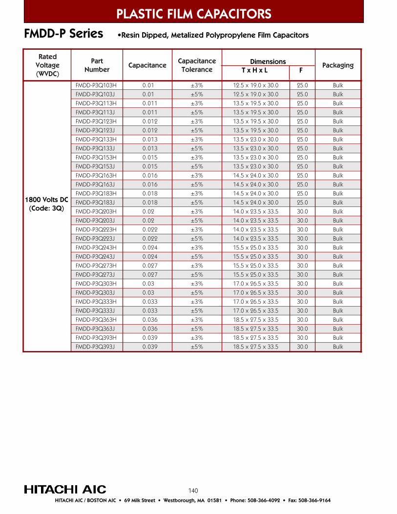
140
detaRegatloV)CDVW(
traPrebmuN
ecnaticapaCecnaticapaC
ecnareloTgnigakcaP
H301Q3P-DDMF 10.0 %3± 0.03x0.91x5.21 0.52 kluB
J301Q3P-DDMF 10.0 %5± 0.03x0.91x5.21 0.52 kluB
H311Q3P-DDMF 110.0 %3± 0.03x5.91x5.31 0.52 kluB
J311Q3P-DDMF 110.0 %5± 0.03x5.91x5.31 0.52 kluB
H321Q3P-DDMF 210.0 %3± 0.03x5.91x5.31 0.52 kluB
J321Q3P-DDMF 210.0 %5± 0.03x5.91x5.31 0.52 kluB
H331Q3P-DDMF 310.0 %3± 0.03x0.32x5.31 0.52 kluB
J331Q3P-DDMF 310.0 %5± 0.03x0.32x5.31 0.52 kluB
H351Q3P-DDMF 510.0 %3± 0.03x0.32x5.31 0.52 kluB
J351Q3P-DDMF 510.0 %5± 0.03x0.32x5.31 0.52 kluB
H361Q3P-DDMF 610.0 %3± 0.03x0.42x5.41 0.52 kluB
J361Q3P-DDMF 610.0 %5± 0.03x0.42x5.41 0.52 kluB
H381Q3P-DDMF 810.0 %3± 0.03x0.42x5.41 0.52 kluB
J381Q3P-DDMF 810.0 %5± 0.03x0.42x5.41 0.52 kluB
H302Q3P-DDMF 20.0 %3± 5.33x5.32x0.41 0.03 kluB
J302Q3P-DDMF 20.0 %5± 5.33x5.32x0.41 0.03 kluB
H322Q3P-DDMF 220.0 %3± 5.33x5.32x0.41 0.03 kluB
J322Q3P-DDMF 220.0 %5± 5.33x5.32x0.41 0.03 kluB
H342Q3P-DDMF 420.0 %3± 5.33x0.52x5.51 0.03 kluB
J342Q3P-DDMF 420.0 %5± 5.33x0.52x5.51 0.03 kluB
H372Q3P-DDMF 720.0 %3± 5.33x0.52x5.51 0.03 kluB
J372Q3P-DDMF 720.0 %5± 5.33x0.52x5.51 0.03 kluB
H303Q3P-DDMF 30.0 %3± 5.33x5.62x0.71 0.03 kluB
J303Q3P-DDMF 30.0 %5± 5.33x5.62x0.71 0.03 kluB
H333Q3P-DDMF 330.0 %3± 5.33x5.62x0.71 0.03 kluB
J333Q3P-DDMF 330.0 %5± 5.33x5.62x0.71 0.03 kluB
H363Q3P-DDMF 630.0 %3± 5.33x5.72x5.81 0.03 kluB
J363Q3P-DDMF 630.0 %5± 5.33x5.72x5.81 0.03 kluB
H393Q3P-DDMF 930.0 %3± 5.33x5.72x5.81 0.03 kluB
J393Q3P-DDMF 930.0 %5± 5.33x5.72x5.81 0.03 kluB
FMDD-P Series •Resin Dipped, Metalized Polypropylene Film Capacitors
PLASTIC FILM CAPACITORS
AICHITACHI AIC / BOSTON AIC • 69 Milk Street • Westborough, MA 01581 • Phone: 508-366-4092 • Fax: 508-366-9164
1800 Volts DC(Code: 3Q)
Dimensions T x H x L F
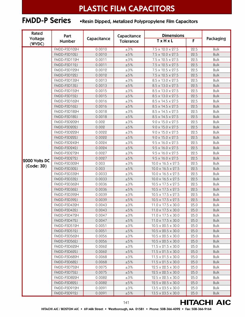
141
detaRegatloV)CDVW(
traPrebmuN
ecnaticapaCecnaticapaC
ecnareloTgnigakcaP
H201D3P-DDMF 0100.0 %3± 5.72x0.21x5.7 5.22 kluBJ201D3P-DDMF 0100.0 %5± 5.72x0.21x5.7 5.22 kluBH211D3P-DDMF 1100.0 %3± 5.72x5.21x5.7 5.22 kluBJ211D3P-DDMF 1100.0 %5± 5.72x5.21x5.7 5.22 kluBH221D3P-DDMF 2100.0 %3± 5.72x5.21x5.7 5.22 kluBJ221D3P-DDMF 2100.0 %5± 5.72x5.21x5.7 5.22 kluBH231D3P-DDMF 3100.0 %3± 5.72x0.31x5.8 5.22 kluBJ231D3P-DDMF 3100.0 %5± 5.72x0.31x5.8 5.22 kluBH251D3P-DDMF 5100.0 %3± 5.72x0.31x5.8 5.22 kluBJ251D3P-DDMF 5100.0 %5± 5.72x0.31x5.8 5.22 kluBH261D3P-DDMF 6100.0 %3± 5.72x5.41x5.8 5.22 kluBJ261D3P-DDMF 6100.0 %5± 5.72x5.41x5.8 5.22 kluBH281D3P-DDMF 8100.0 %3± 5.72x5.41x5.8 5.22 kluBJ281D3P-DDMF 8100.0 %5± 5.72x5.41x5.8 5.22 kluBH202D3P-DDMF 200.0 %3± 5.72x0.51x0.9 5.22 kluBJ202D3P-DDMF 200.0 %5± 5.72x0.51x0.9 5.22 kluBH222D3P-DDMF 2200.0 %3± 5.72x0.51x0.9 5.22 kluBJ222D3P-DDMF 2200.0 %5± 5.72x0.51x0.9 5.22 kluBH242D3P-DDMF 4200.0 %3± 5.72x0.61x5.9 5.22 kluBJ242D3P-DDMF 4200.0 %5± 5.72x0.61x5.9 5.22 kluBH272D3P-DDMF 7200.0 %3± 5.72x0.61x5.9 5.22 kluBJ272D3P-DDMF 7200.0 %5± 5.72x0.61x5.9 5.22 kluBH203D3P-DDMF 300.0 %3± 5.72x5.61x0.01 5.22 kluBJ203D3P-DDMF 300.0 %5± 5.72x5.61x0.01 5.22 kluBH233D3P-DDMF 3300.0 %3± 5.72x5.61x0.01 5.22 kluBJ233D3P-DDMF 3300.0 %5± 5.72x5.61x0.01 5.22 kluBH263D3P-DDMF 6300.0 %3± 5.72x5.71x5.01 5.22 kluBJ263D3P-DDMF 6300.0 %5± 5.72x5.71x5.01 5.22 kluBH293D3P-DDMF 9300.0 %3± 5.72x5.71x5.01 5.22 kluBJ293D3P-DDMF 9300.0 %5± 5.72x5.71x5.01 5.22 kluBH234D3P-DDMF 3400.0 %3± 0.03x5.71x0.11 0.52 kluBJ234D3P-DDMF 3400.0 %5± 0.03x5.71x0.11 0.52 kluBH274D3P-DDMF 7400.0 %3± 0.03x5.71x0.11 0.52 kluBJ274D3P-DDMF 7400.0 %5± 0.03x5.71x0.11 0.52 kluBH215D3P-DDMF 1500.0 %3± 0.03x5.02x5.01 0.52 kluBJ215D3P-DDMF 1500.0 %5± 0.03x5.02x5.01 0.52 kluBH265D3P-DDMF 6500.0 %3± 0.03x5.02x5.01 0.52 kluBJ265D3P-DDMF 6500.0 %5± 0.03x5.02x5.01 0.52 kluBH226D3P-DDMF 2600.0 %3± 0.03x5.12x5.11 0.52 kluBJ226D3P-DDMF 2600.0 %5± 0.03x5.12x5.11 0.52 kluBH286D3P-DDMF 8600.0 %3± 0.03x5.12x5.11 0.52 kluBJ286D3P-DDMF 8600.0 %5± 0.03x5.12x5.11 0.52 kluBH257D3P-DDMF 5700.0 %3± 0.03x5.22x5.21 0.52 kluBJ257D3P-DDMF 5700.0 %5± 0.03x5.22x5.21 0.52 kluBH228D3P-DDMF 2800.0 %3± 0.03x5.22x5.21 0.52 kluBJ228D3P-DDMF 2800.0 %5± 0.03x5.22x5.21 0.52 kluBH219D3P-DDMF 1900.0 %3± 0.03x5.32x5.31 0.52 kluBJ219D3P-DDMF 1900.0 %5± 0.03x5.32x5.31 0.52 kluB
PLASTIC FILM CAPACITORS
AICHITACHI AIC / BOSTON AIC • 69 Milk Street • Westborough, MA 01581 • Phone: 508-366-4092 • Fax: 508-366-9164
FMDD-P Series •Resin Dipped, Metalized Polypropylene Film Capacitors
Dimensions T x H x L F
2000 Volts DC(Code: 3D)
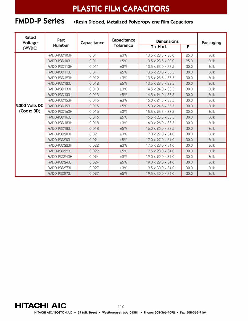
142
detaRegatloV)CDVW(
traPrebmuN
ecnaticapaCecnaticapaC
ecnareloTgnigakcaP
H301D3P-DDMF 10.0 %3± 0.03x5.32x5.31 0.52 kluB
J301D3P-DDMF 10.0 %5± 0.03x5.32x5.31 0.52 kluB
H311D3P-DDMF 110.0 %3± 5.33x0.32x5.31 0.03 kluB
J311D3P-DDMF 110.0 %5± 5.33x0.32x5.31 0.03 kluB
H321D3P-DDMF 210.0 %3± 5.33x5.32x5.31 0.03 kluB
J321D3P-DDMF 210.0 %5± 5.33x5.32x5.31 0.03 kluB
H331D3P-DDMF 310.0 %3± 5.33x0.42x5.41 0.03 kluB
J331D3P-DDMF 310.0 %5± 5.33x0.42x5.41 0.03 kluB
H351D3P-DDMF 510.0 %3± 5.33x5.42x0.51 0.03 kluB
J351D3P-DDMF 510.0 %5± 5.33x5.42x0.51 0.03 kluB
H361D3P-DDMF 610.0 %3± 5.33x5.52x5.51 0.03 kluB
J361D3P-DDMF 610.0 %5± 5.33x5.52x5.51 0.03 kluB
H381D3P-DDMF 810.0 %3± 5.33x0.62x0.61 0.03 kluB
J381D3P-DDMF 810.0 %5± 5.33x0.62x0.61 0.03 kluB
H302D3P-DDMF 20.0 %3± 0.43x0.72x0.71 0.03 kluB
J302D3P-DDMF 20.0 %5± 0.43x0.72x0.71 0.03 kluB
H322D3P-DDMF 220.0 %3± 0.43x0.82x5.71 0.03 kluB
J322D3P-DDMF 220.0 %5± 0.43x0.82x5.71 0.03 kluB
H342D3P-DDMF 420.0 %3± 0.43x0.92x0.91 0.03 kluB
J342D3P-DDMF 420.0 %5± 0.43x0.92x0.91 0.03 kluB
H372D3P-DDMF 720.0 %3± 0.43x0.03x5.91 0.03 kluB
J372D3P-DDMF 720.0 %5± 0.43x0.03x5.91 0.03 kluB
FMDD-P Series •Resin Dipped, Metalized Polypropylene Film Capacitors
PLASTIC FILM CAPACITORS
AICHITACHI AIC / BOSTON AIC • 69 Milk Street • Westborough, MA 01581 • Phone: 508-366-4092 • Fax: 508-366-9164
2000 Volts DC(Code: 3D)
Dimensions T x H x L F
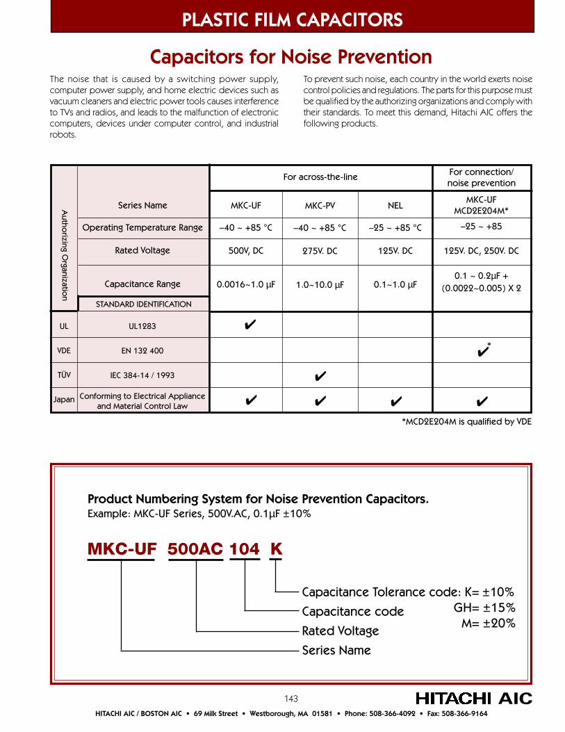
143
PLASTIC FILM CAPACITORS
AICHITACHI AIC / BOSTON AIC • 69 Milk Street • Westborough, MA 01581 • Phone: 508-366-4092 • Fax: 508-366-9164
Capacitors for Noise PreventionThe noise that is caused by a switching power supply,computer power supply, and home electric devices such asvacuum cleaners and electric power tools causes interferenceto TVs and radios, and leads to the malfunction of electroniccomputers, devices under computer control, and industrialrobots.
To prevent such noise, each country in the world exerts noisecontrol policies and regulations. The parts for this purpose mustbe qualified by the authorizing organizations and comply withtheir standards. To meet this demand, Hitachi AIC offers thefollowing products.
Product Numbering System for Noise Prevention Capacitors.Example: MKC-UF Series, 500V.AC, 0.1µF ±10%
Capacitance Tolerance code: K= ±10%
Capacitance code
Rated Voltage
Series Name
MKC-UF 500AC 104 K
GH= ±15%M= ±20%
MKC-UF
–40 ~ +85 °C
500V, DC
0.0016~1.0 µF
For across-the-line For connection/noise prevention
UL
VDE
TÜV
Japan
Autho
rizing Organizatio
n
STANDARD IDENTIFICATION
UL1283
EN 132 400
IEC 384-14 / 1993
Conforming to Electrical Applianceand Material Control Law
Series Name
Operating Temperature Range
Rated Voltage
Capacitance Range
MKC-UFMCD2E204M*
–25 ~ +85
125V. DC, 250V. DC
0.1 ~ 0.2µF +(0.0022~0.005) X 2
MKC-PV
–40 ~ +85 °C
275V. DC
1.0~10.0 µF
NEL
–25 ~ +85 °C
125V. DC
0.1~1.0 µF
*
*MCD2E204M is qualified by VDE
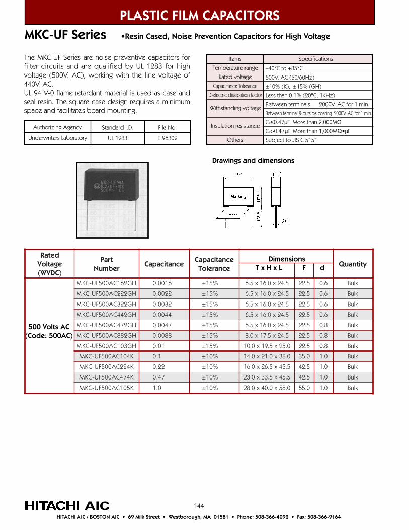
144
MKC-UF Series •Resin Cased, Noise Prevention Capacitors for High Voltage
PLASTIC FILM CAPACITORS
AICHITACHI AIC / BOSTON AIC • 69 Milk Street • Westborough, MA 01581 • Phone: 508-366-4092 • Fax: 508-366-9164
detaRegatloV)CDVW(
traPrebmuN
ecnaticapaCecnaticapaC
ecnareloTytitnauQ
HG261CA005FU-CKM 6100.0 %51± 5.42x0.61x5.6 5.22 6.0 kluB
HG222CA005FU-CKM 2200.0 %51± 5.42x0.61x5.6 5.22 6.0 kluB
HG223CA005FU-CKM 2300.0 %51± 5.42x0.61x5.6 5.22 6.0 kluB
HG244CA005FU-CKM 4400.0 %51± 5.42x0.61x5.6 5.22 6.0 kluB
HG274CA005FU-CKM 7400.0 %51± 5.42x0.61x5.6 5.22 8.0 kluB
HG288CA005FU-CKM 8800.0 %51± 5.42x5.71x0.8 5.22 8.0 kluB
HG301CA005FU-CKM 10.0 %51± 0.52x5.91x0.01 5.22 8.0 kluB
K401CA005FU-CKM 1.0 %01± 0.83x0.12x0.41 0.53 0.1 kluB
K422CA005FU-CKM 22.0 %01± 5.54x5.62x0.61 5.24 0.1 kluB
K474CA005FU-CKM 74.0 %01± 5.54x5.33x0.32 5.24 0.1 kluB
K501CA005FU-CKM 0.1 %01± 0.85x0.04x0.82 0.55 0.1 kluB
Dimensions T x H x L F d
Items
Temperature range
Rated voltage
Capacitance Tolerance
Dielectric dissipation factor
Withstanding voltage
Insulation resistance
Others
–40°C to +85°C
500V. AC (50/60Hz)
±10% (K), ±15% (GH)
Less than 0.1% (20°C, 1KHz)
Between terminals 2000V. AC for 1 min.
Between terminal & outside coating 2000V. AC for 1 min.
CR≤0.47µF More than 2,000MΩCR>0.47µF More than 1,000MΩ•µF
Subject to JIS C 5151
SpecificationsThe MKC-UF Series are noise preventive capacitors forfilter circuits and are qualified by UL 1283 for highvoltage (500V. AC), working with the line voltage of440V. AC.UL 94 V-0 flame retardant material is used as case andseal resin. The square case design requires a minimumspace and facilitates board mounting.
Drawings and dimensions
500 Volts AC(Code: 500AC)
Authorizing Agency
Underwriters Laboratory
Standard I.D.
UL 1283
File No.
E 96302

145
detaRegatloV
traPrebmuN
ecnaticapaCecnaticapaC
ecnareloTgnigakcaP
K501CA572VP-CKM 0.1 %01± 0.83x0.12x0.41 0.53 kluBK551CA572VP-CKM 5.1 %01± 0.83x0.03x0.81 0.53 kluBK522CA572VP-CKM 2.2 %01± 0.83x0.03x0.81 0.53 kluBK533CA572VP-CKM 3.3 %01± 5.54x5.33x0.32 5.24 kluBK574CA572VP-CKM 7.4 %01± 5.54x5.33x0.32 5.24 kluBK586CA572VP-CKM 8.6 %01± 0.85x0.04x0.82 0.55 kluBK601CA572VP-CKM 0.01 %01± 0.85x0.04x0.82 0.55 kluB
PLASTIC FILM CAPACITORS
AICHITACHI AIC / BOSTON AIC • 69 Milk Street • Westborough, MA 01581 • Phone: 508-366-4092 • Fax: 508-366-9164
275 Volts AC(Code: 275AC)
MKC-PV Series •Resin Cased, Metalized Polypropylene Noise Prevention Capacitors•Conforming to IEC 38414 2nd Edition, class x2)
Large capacitance capacitors for noise prevention thatcan be easily inserted into a printed board throughimprovement of conventional MTB-PV type outercovering into a flame retardant resin-encased type.
Authorizing Agency
TÜV
Standard I.D.EN 132 400 (X2)
IE C 384-14:1993+A1
File No.
R 9750271
NEL Series •Resin Cased Noise Prevention Capacitors with Protective Mechanism
Items
Temperature range
Rated voltage
Capacitance Tolerance
Dielectric dissipation factor
Withstanding voltage
Insulation resistance
Others
–40°C to +85°C
500V. AC (50/60Hz)
±10% (K), ±15% (GH)
Less than 0.1% (20°C, 1KHz)
Between terminals 2000V. AC for 1 min.
Between terminal & outside coating 2000V. AC for 1 min.
CR≤0.47µF More than 2,000MΩCR>0.47µF More than 1,000MΩ•µF
Subject to JIS C 5151
Specifications
The NEL Series features a protective mechanism which isactivated in the event of a lighting surge. It has excellentimpedance characteristics similar to those in Hitachi AIC’sconventional capacitors, and uses flame retardant lead
Items
Temperature range
Rated voltage
Capacitance Tolerance
Dissipation factor
Withstanding voltage
Insulation resistanceOthers
–40°C to +85°C
275V. AC (50/60Hz)
±10% (K)
Less than 0.1% (20°C, 1KHz)
Between terminals 1.183V. AC for 1 min.
Between terminal & outside coating 2050V. AC for 1 min.
Between terminals More than 5,000MΩSubject to JIS C 5151
Specifications
Dimensions T x H x L F
detaRegatloV
traPrebmuN
ecnaticapaCecnaticapaC
ecnareloTgnigakcaP
M401B2LEN 1.0 %02± 5.62x0.91x0.9 kluBM451B2LEN 51.0 %02± 5.62x0.91x0.9 kluBM422B2LEN 22.0 %02± 5.62x0.91x0.9 kluBM433B2LEN 33.0 %02± 5.62x0.91x0.9 kluBM474B2LEN 74.0 %02± 5.62x0.91x0.9 kluBM486B2LEN 86.0 %02± 5.62x0.91x5.01 kluBM501B2LEN 0.1 %02± 5.62x0.91x5.01 kluB
wire AWG22 (UL 1015). The NEL requires a minimum ofspace in applications such as washing machines, vacuumcleaners, power tools, etc.
125 Volts AC(Code: 2B)
DimensionsT x H x L
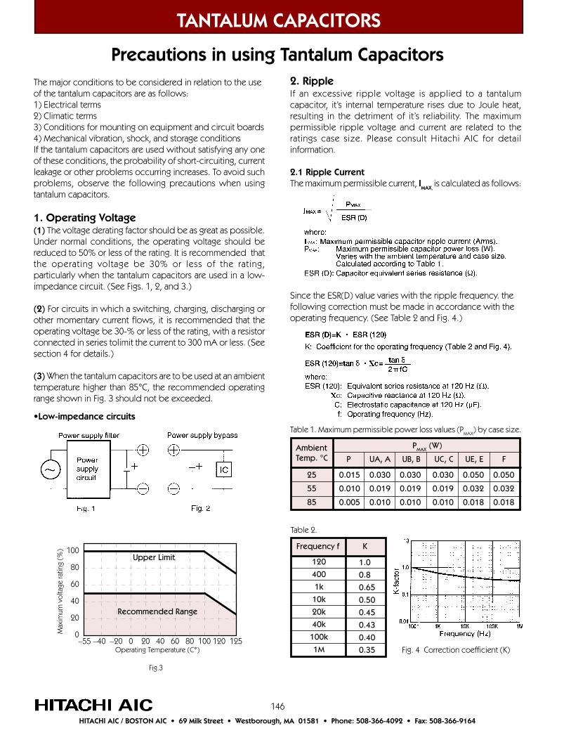
146
2. RippleIf an excessive ripple voltage is applied to a tantalumcapacitor, it’s internal temperature rises due to Joule heat,resulting in the detriment of it’s reliability. The maximumpermissible ripple voltage and current are related to theratings case size. Please consult Hitachi AIC for detailinformation.
2.1 Ripple CurrentThe maximum permissible current, IMAX,
is calculated as follows:
Since the ESR(D) value varies with the ripple frequency. thefollowing correction must be made in accordance with theoperating frequency. (See Table 2 and Fig. 4.)
Table 1. Maximum permissible power loss values (PMAX
) by case size.
TANTALUM CAPACITORS
AICHITACHI AIC / BOSTON AIC • 69 Milk Street • Westborough, MA 01581 • Phone: 508-366-4092 • Fax: 508-366-9164
The major conditions to be considered in relation to the useof the tantalum capacitors are as follows:1) Electrical terms2) Climatic terms3) Conditions for mounting on equipment and circuit boards4) Mechanical vibration, shock, and storage conditionsIf the tantalum capacitors are used without satisfying any oneof these conditions, the probability of short-circuiting, currentleakage or other problems occurring increases. To avoid suchproblems, observe the following precautions when usingtantalum capacitors.
1. Operating Voltage(1) The voltage derating factor should be as great as possible.Under normal conditions, the operating voltage should bereduced to 50% or less of the rating. It is recommended thatthe operating voltage be 30% or less of the rating,particularly when the tantalum capacitors are used in a low-impedance circuit. (See Figs. 1, 2, and 3.)
(2) For circuits in which a switching, charging, discharging orother momentary current flows, it is recommended that theoperating voltage be 30-% or less of the rating, with a resistorconnected in series tolimit the current to 300 mA or less. (Seesection 4 for details.)
(3) When the tantalum capacitors are to be used at an ambienttemperature higher than 85°C, the recommended operatingrange shown in Fig. 3 should not be exceeded.
•Low-impedance circuits
Precautions in using Tantalum Capacitors
100
80
60
40
20
0Max
imum
vol
tage
ratin
g (%
)
–55 –40 –20 0 20 40 60 80 100 120 125Operating Temperature (C°)
Fig.3
Frequency f K
120
400
1k
10k
20k
40k
100k
1M
1.0
0.8
0.65
0.50
0.45
0.43
0.40
0.35
Table 2.
Fig. 4 Correction coefficient (K)
Upper Limit
Recommended Range
AmbientTemp. °C
25
55
85
0.015 0.030 0.030 0.030 0.050 0.050
0.010 0.019 0.019 0.019 0.032 0.032
0.005 0.010 0.010 0.010 0.018 0.018
PMAX (W)
P UA, A UB, B UC, C UE, E F
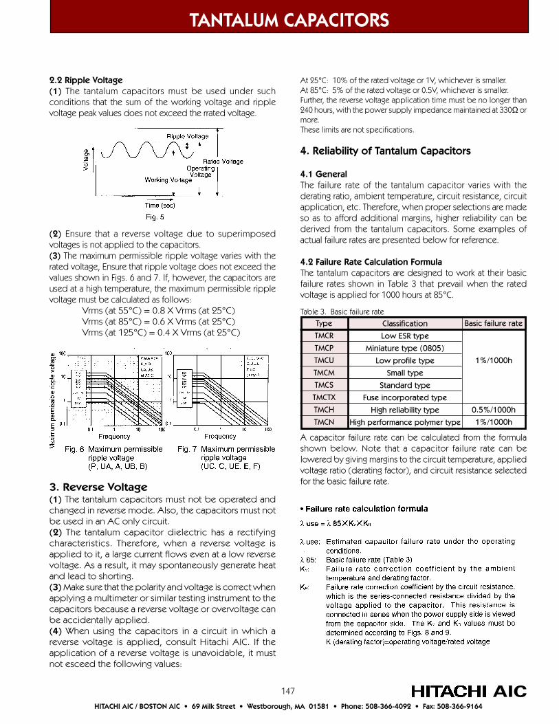
147
At 25°C: 10% of the rated voltage or 1V, whichever is smaller.At 85°C: 5% of the rated voltage or 0.5V, whichever is smaller.Further, the reverse voltage application time must be no longer than240 hours, with the power supply impedance maintained at 330Ω ormore.These limits are not specifications.
4. Reliability of Tantalum Capacitors
4.1 GeneralThe failure rate of the tantalum capacitor varies with thederating ratio, ambient temperature, circuit resistance, circuitapplication, etc. Therefore, when proper selections are madeso as to afford additional margins, higher reliability can bederived from the tantalum capacitors. Some examples ofactual failure rates are presented below for reference.
4.2 Failure Rate Calculation FormulaThe tantalum capacitors are designed to work at their basicfailure rates shown in Table 3 that prevail when the ratedvoltage is applied for 1000 hours at 85°C.
A capacitor failure rate can be calculated from the formulashown below. Note that a capacitor failure rate can belowered by giving margins to the circuit temperature, appliedvoltage ratio (derating factor), and circuit resistance selectedfor the basic failure rate.
TANTALUM CAPACITORS
AICHITACHI AIC / BOSTON AIC • 69 Milk Street • Westborough, MA 01581 • Phone: 508-366-4092 • Fax: 508-366-9164
2.2 Ripple Voltage(1) The tantalum capacitors must be used under suchconditions that the sum of the working voltage and ripplevoltage peak values does not exceed the rrated voltage.
(2) Ensure that a reverse voltage due to superimposedvoltages is not applied to the capacitors.(3) The maximum permissible ripple voltage varies with therated voltage, Ensure that ripple voltage does not exceed thevalues shown in Figs. 6 and 7. If, however, the capacitors areused at a high temperature, the maximum permissible ripplevoltage must be calculated as follows:
Vrms (at 55°C) = 0.8 X Vrms (at 25°C)Vrms (at 85°C) = 0.6 X Vrms (at 25°C)Vrms (at 125°C) = 0.4 X Vrms (at 25°C)
3. Reverse Voltage(1) The tantalum capacitors must not be operated andchanged in reverse mode. Also, the capacitors must notbe used in an AC only circuit.(2) The tantalum capacitor dielectric has a rectifyingcharacteristics. Therefore, when a reverse voltage isapplied to it, a large current flows even at a low reversevoltage. As a result, it may spontaneously generate heatand lead to shorting.(3) Make sure that the polarity and voltage is correct whenapplying a multimeter or similar testing instrument to thecapacitors because a reverse voltage or overvoltage canbe accidentally applied.(4) When using the capacitors in a circuit in which areverse voltage is applied, consult Hitachi AIC. If theapplication of a reverse voltage is unavoidable, it mustnot esceed the following values:
Type
TMCR
TMCP
TMCU
TMCM
TMCS
TMCTX
TMCH
TMCN
Classification
Low ESR type
Miniature type (0805)
Low profile type
Small type
Standard type
Fuse incorporated type
High reliability type
High performance polymer type
Basic failure rate
1%/1000h
0.5%/1000h
1%/1000h
Table 3. Basic failure rate
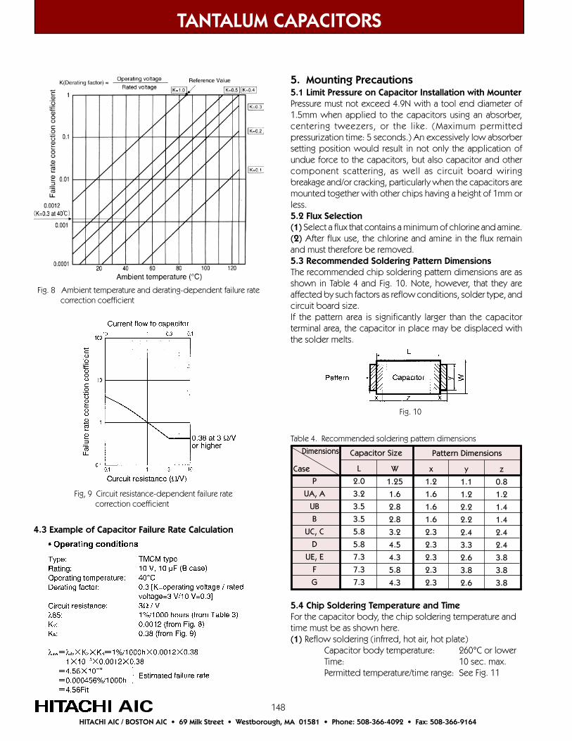
148
TANTALUM CAPACITORS
AICHITACHI AIC / BOSTON AIC • 69 Milk Street • Westborough, MA 01581 • Phone: 508-366-4092 • Fax: 508-366-9164
Fig. 8 Ambient temperature and derating-dependent failure rate correction coefficient
Fig, 9 Circuit resistance-dependent failure rate correction coefficient
4.3 Example of Capacitor Failure Rate Calculation
5. Mounting Precautions5.1 Limit Pressure on Capacitor Installation with MounterPressure must not exceed 4.9N with a tool end diameter of1.5mm when applied to the capacitors using an absorber,centering tweezers, or the like. (Maximum permittedpressurization time: 5 seconds.) An excessively low absorbersetting position would result in not only the application ofundue force to the capacitors, but also capacitor and othercomponent scattering, as well as circuit board wiringbreakage and/or cracking, particularly when the capacitors aremounted together with other chips having a height of 1mm orless.5.2 Flux Selection(1) Select a flux that contains a minimum of chlorine and amine.(2) After flux use, the chlorine and amine in the flux remainand must therefore be removed.5.3 Recommended Soldering Pattern DimensionsThe recommended chip soldering pattern dimensions are asshown in Table 4 and Fig. 10. Note, however, that they areaffected by such factors as reflow conditions, solder type, andcircuit board size.If the pattern area is significantly larger than the capacitorterminal area, the capacitor in place may be displaced withthe solder melts.
P
UA, A
UB
B
UC, C
D
UE, E
F
G
L
2.0
3.2
3.5
3.5
5.8
5.8
7.3
7.3
7.3
Case
Dimensions
W
1.25
1.6
2.8
2.8
3.2
4.5
4.3
5.8
4.3
x
1.2
1.6
1.6
1.6
2.3
2.3
2.3
2.3
2.3
y
1.1
1.2
2.2
2.2
2.4
3.3
2.6
3.8
2.6
z
0.8
1.2
1.4
1.4
2.4
2.4
3.8
3.8
3.8
Capacitor Size Pattern Dimensions
Table 4. Recommended soldering pattern dimensions
Fig. 10
5.4 Chip Soldering Temperature and TimeFor the capacitor body, the chip soldering temperature andtime must be as shown here.(1) Reflow soldering (infrred, hot air, hot plate)
Capacitor body temperature: 260°C or lowerTime: 10 sec. max.Permitted temperature/time range: See Fig. 11
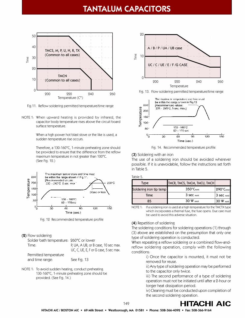
149
TANTALUM CAPACITORS
AICHITACHI AIC / BOSTON AIC • 69 Milk Street • Westborough, MA 01581 • Phone: 508-366-4092 • Fax: 508-366-9164
NOTE 1: When upward heating is provided by infrared, thecapacitor body temperature rises above the circuit boardsurface temperature.
When a high power hot blast stove or the like is used, asudden temperature rise occurs.
Therefore, a 130-160°C, 1-minute preheating zone shouldbe provided to ensure that the difference from the reflowmaximum temperature in not greater than 100°C.(See Fig. 12.)
50
40
30
20
10
0
Tim
e
200 220 240 260Temperature (C°)
Fig.11. Reflow soldering permitted temperature/time range
TMCN(Common to all cases)
TMCS, M, P, U, H, R, TX(Common to all cases)
Fig. 12 Recommended temperature profile
(2) Flow soldering Solder bath temperature: 260°C or lower Time: P, UA, A UB, or B case, 10 sec max.
UC, C, UE, E, F or G case, 5 sec max. Permitted temperature and time range: See Fig. 13
NOTE 1: To avoid sudden heating, conduct preheating.130-160°C, 1-minute preheating zone should beprovided. (See Fig. 14.)
20
10
0
Tim
e
200 220 240 260
UC / C / UE / E / F /G CASE
A / B / P / UA / UB case
Temperature
Fig. 13. Flow soldering permitted temperature/time range
Fig. 14. Recommended temperature profile
(3) Soldering with an ironThe use of a soldering iron should be avoided whereverpossible. If it is unavoidable, follow the instructions set forthin Table 5.
NOTE 1: If a soldering iron is used at a high temperature for the TMCTX typewhich incorporates a thermal fuse, the fuse opens. Due care mustbe used to avoid this adverse situation.
(4) Repetition of solderingThe soldering conditions for soldering operations (1) through(3) above are established on the presumption that only onetype of soldering operation is conducted.When repeating a reflow soldering or a combined flow-and-reflow soldering operation, comply with the followingconditions:
i) Once the capacitor is mounted, it must not beremoved for reuse.ii) Any type of soldering operation may be performedto the capacitor only twice.iii) The second performance of a type of solderingoperation must not be initiated until after a 2-hour orlonger heat dissipation period.iv) Cleaning must be conducted upon completion ofthe second soldering operation.
Type
Soldering iron tip temp
Time
85
350°CMAX
3 sec MAX
30 W MAX
TMCR, TMCS, TMCM, TMCU, TMCH
290°CMAX
3 sec MAX
30 W MAX
Table 5.

150
TANTALUM CAPACITORS
AICHITACHI AIC / BOSTON AIC • 69 Milk Street • Westborough, MA 01581 • Phone: 508-366-4092 • Fax: 508-366-9164
5.5 Cleaning after MountingThe following solvents are usable when cleaning thecapacitors after mounting. NEVER use a highly active solvert.• Halogen organic solvent (HCFC225, etc.)• Alcohol solvent (IPA. ethanol, etc.)• Petroleum solvent, alkali saponifying agent, water, etc.
Circuit board cleaning must be conducted at a temperature ofnot higher than 50°C and for an immersion time of not longerthan 30 minutes. When an ultrasonic cleaning method is used,cleaning must be conducted at a frequency of 48kHz or lower,at a vibration output of 0.02 W/cm3, at a temperature of nothigher than 40°C, and for a time of 5 minutes or less.
NOTE 1: Care must be exercised in the cleaning process sothat the mounted capacitor will not come intocontact with any cleaned object or the like, or willnot get rubbed by a stiff brush or similar object. Ifsuch precautions are not taken, particularly when theultrasonic cleaning method is employed, terminalbreakage may occur.
NOTE 2: When performing ultrasonic cleaning underconditions other than stated here, conductadequate advance checkout.
6. Long-term StockBefore using capacitors that have been stored for more than2 years, please contact Hitachi AIC.
7. Other(1) For further details refer to EIAJ RCR-2368, Precautions andGuidelines for Using Electronic Device Tantalum Capacitors.(2) If you have any questions, feel free to contact you localHitachi AIC representative. They can be located by visiting ourweb site at www.hitachiaic.com.
To meet the recent trends for electronic products smaller in size and lighter in weight, chip type tantalum capacitor manufacturershave downsized their products by various methods. Of these methods, the method of ensuring a required capacity by thinning thedielectric film greatly reduces the withstanding voltage characteristics. The most common and effective method therefore, is usingfine tantalum powder to enlarge the surface area of the anode per unit area.Hitachi AIC’s TMC type tantalum capacitors have been enlarged in capacity and reduced in size by taking full advantage of finepowder known as “high-CV powder”. In recent years downsizing and increased capacity of multilayer ceramic capacitors hasbeen achieved. To keep the competitive advantage held by Hitachi AIC’s TMC chip capacitors we use only the best high-CVpowder to upgrade the TMC family of products.Hitachi AIC is currently developing the following families of products:
1). Series with a larger capacity than the TMCM type2). Series with a larger capacity than the TMCP type (2010mm)3). Series with a larger capacity than the TMCU type (thin type, low-height version of the TMCM type)4). Series TMCJ type (1608mm)
About downsizing (upgrading)
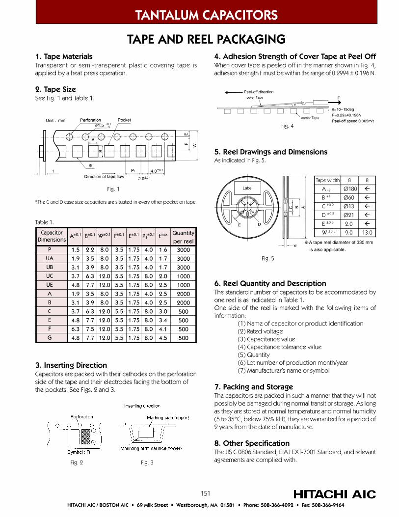
151
TANTALUM CAPACITORS
AICHITACHI AIC / BOSTON AIC • 69 Milk Street • Westborough, MA 01581 • Phone: 508-366-4092 • Fax: 508-366-9164
TAPE AND REEL PACKAGING1. Tape MaterialsTransparent or semi-transparent plastic covering tape isapplied by a heat press operation.
2. Tape SizeSee Fig. 1 and Table 1.
Fig. 1
*The C and D case size capacitors are situated in every other pocket on tape.
P
UA
UB
UC
UE
A
B
C
E
F
G
A±0.1
1.5
1.9
3.1
3.7
4.8
1.9
3.1
3.7
4.8
6.3
4.8
CapacitorDimensions
Table 1.
B±0.1
2.2
3.5
3.9
6.3
7.7
3.5
3.9
6.3
7.7
7.5
7.7
W±0.1
8.0
8.0
8.0
12.0
12.0
8.0
8.0
12.0
12.0
12.0
12.0
F±0.1
3.5
3.5
3.5
5.5
5.5
3.5
3.5
5.5
5.5
5.5
5.5
E±0.1
1.75
1.75
1.75
1.75
1.75
1.75
1.75
1.75
1.75
1.75
1.75
P1±0.1
4.0
4.0
4.0
8.0
8.0
4.0
4.0
8.0
8.0
8.0
8.0
tmax
1.6
1.7
1.7
2.0
2.5
2.5
2.5
3.0
3.4
4.1
4.5
Quantityper reel
3000
3000
3000
1000
1000
2000
2000
500
500
500
500
3. Inserting DirectionCapacitors are packed with their cathodes on the perforationside of the tape and their electrodes facing the bottom ofthe pockets. See Figs. 2 and 3.
Fig. 2 Fig. 3
4. Adhesion Strength of Cover Tape at Peel OffWhen cover tape is peeled off in the manner shown in Fig. 4,adhesion strength F must be within the range of 0.2994 ± 0.196 N.
Fig. 4
5. Reel Drawings and DimensionsAs indicated in Fig. 5.
6. Reel Quantity and DescriptionThe standard number of capacitors to be accommodated byone reel is as indicated in Table 1.One side of the reel is marked with the following items ofinformation:
(1) Name of capacitor or product identification(2) Rated voltage(3) Capacitance value(4) Capacitance tolerance value(5) Quantity(6) Lot number of production month/year(7) Manufacturer’s name or symbol
7. Packing and StorageThe capacitors are packed in such a manner that they will notpossibly be damaged during normal transit or storage. As longas they are stored at normal temperature and normal humidity(5 to 35°C, below 75% RH), they are warranted for a period of2 years from the date of manufacture.
8. Other SpecificationThe JIS C 0806 Standard, EIAJ EXT-7001 Standard, and relevantagreements are complied with.
Tape width
A -3 B +1
C ±0.2
D ±0.5
E ±0.5
W ±0.3
8
Ø180
Ø60
Ø13
Ø21
2.0
9.0
8
13.0
Fig. 5
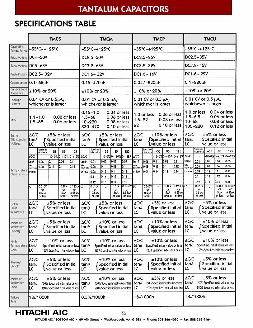
152
TANTALUM CAPACITORS
AICHITACHI AIC / BOSTON AIC • 69 Milk Street • Westborough, MA 01581 • Phone: 508-366-4092 • Fax: 508-366-9164
OperatingTemp. Range
Rated Voltage
Surge Voltage
Derated Voltage
Capacitance
CapacitanceTolerance
LeakageCurrent
tan∂
SurgeWithstandingVoltage
TemperatureCharacteristics
SolderHeatResistance
MoistureResistanceLeaving
HighTemperatureLoad
ThermalShock
MoistureResistanceLoad
FailureRate
SPECIFICATIONS TABLE
TMCUTMCMTMCS TMCP

153
TANTALUM CAPACITORS
AICHITACHI AIC / BOSTON AIC • 69 Milk Street • Westborough, MA 01581 • Phone: 508-366-4092 • Fax: 508-366-9164
TMCTXTMCHTMCR Test ConditionsJIS C5102-1994

154
TANTALUM CAPACITORS
AICHITACHI AIC / BOSTON AIC • 69 Milk Street • Westborough, MA 01581 • Phone: 508-366-4092 • Fax: 508-366-9164
Resin Molded Chip Capcitors
Product Numbering System for Tantalum Chip CapacitorsExample: TMCS Series, A Cse Size,16V.DC, 1µF ±20%, Carrier Tape Packaging, Polarity Code
Packing Polarity code
Packing Method
Capacitance Tolerance code
Capacitance code
Rated Voltage code
Case code
Series Name
TMCS A 1C 105 M T R
±10%: K (standard)
±20: M
Capacitance Code: To determine Capacitance code use the Capacitance followed by thenumber of decimal places. Using the above example of 105: 1.0 + 5 decimal places = 1.00000
This Section Contains: TMCS Series –55~+125·C. Resin Molded Chip, Standard Type
TMCM Series –55~+125°C. Resin Molded Chip, Small-size Type
TMCP Series –55~+125°C. Resin Molded Chip, Ultra Small-size Type
TMCU Series –55~+125°C. Resin molded Chip, thin Type
TMCR Series –55~+125°C. Resin Molded Chip, Low ESR Type
TMCH Series –55~+125°C. Resin Molded Chip, High Reliability Type
TMCTX Series –55~+125°C. Resin Molded Chip, High Reliability with Built-in Fuse
TMCN Series –55~+105°C. Resin Molded Chip, High Performance Type

155
TANTALUM CAPACITORS
AICHITACHI AIC / BOSTON AIC • 69 Milk Street • Westborough, MA 01581 • Phone: 508-366-4092 • Fax: 508-366-9164
TMCS Series •Standard Tantalum Chip Capacitors
The TMCS Series is a standard type that is most widelyused among tantalum chip capacitors. This product hashigh solder heat resistance and is suitable for automatedmounting.
The TMCS Series offers both excellent frequencycharacteristics and excellent impedance characteristics.
Jan
n
A
N
a
Feb
p
B
P
b
Mar
q
C
Q
c
Sep
w
J
W
j
Aug
v
H
V
h
Jul
u
G
U
g
Jun
t
F
T
f
May
s
E
S
e
Apr
r
D
R
d
Dec
n
M
Z
m
Nov
n
L
Y
l
Oct
n
K
X
k
Month
Year
2000
2001
2002
2003
Tantalum Capacitor Date Code Table
A, B Case C, E Case
Simplified code of nominal capacitance (A7: 10µF)
+–
Note: The simplified code is subject to JIS C 5143 10.1.2.
A7a Anode Indication belt markDate Code(for manufacturing in January, 2003)
1016a
Nominal capacitance value (10µF)
Anode Indication belt mark
Date Code(for manufacturing in January, 2003)
+–Rated voltage (16V)
TMCS Product Markings
Outline Drawings and Dimensions
Anode Indication belt mark
For Specifications see Table on Page 152.
TMCS Case Code Table
CaseCode
A
B
C
E
L ±0.2
3.2
3.5
5.8
7.3
Dimensions
W ±0.2
1.6
2.8
3.2
4.3 ±0.3
H ±0.2
1.6
1.9
2.5
2.8
l ±0.3
0.7
0.8
1.3
1.3
a ±0.2
1.2
2.2
2.2
2.4
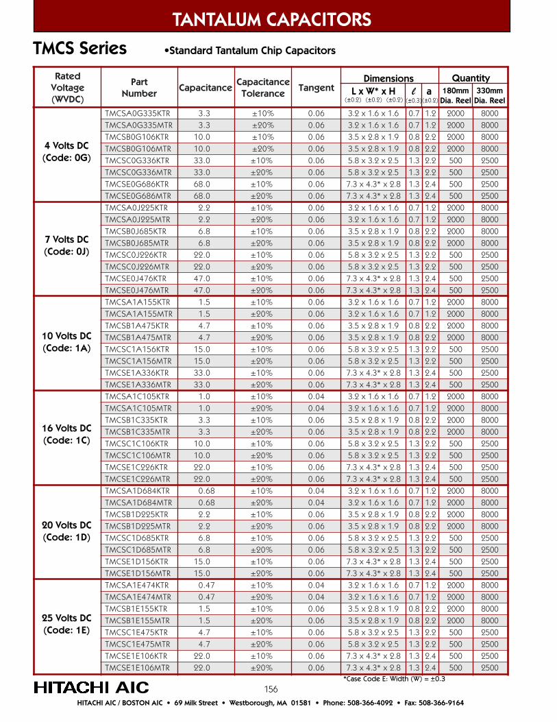
156
TANTALUM CAPACITORS
AICHITACHI AIC / BOSTON AIC • 69 Milk Street • Westborough, MA 01581 • Phone: 508-366-4092 • Fax: 508-366-9164
TMCS Series •Standard Tantalum Chip Capacitors
detaRegatloV)CDVW(
traPrebmuN
ecnaticapaCecnaticapaC
ecnareloTtnegnaT
RTK533G0ASCMT 3.3 %01± 60.0 6.1x6.1x2.3 7.0 2.1 0002 0008RTM533G0ASCMT 3.3 %02± 60.0 6.1x6.1x2.3 7.0 2.1 0002 0008
RTK601G0BSCMT 0.01 %01± 60.0 9.1x8.2x5.3 8.0 2.2 0002 0008RTM601G0BSCMT 0.01 %02± 60.0 9.1x8.2x5.3 8.0 2.2 0002 0008RTK633G0CSCMT 0.33 %01± 60.0 5.2x2.3x8.5 3.1 2.2 005 0052RTM633G0CSCMT 0.33 %02± 60.0 5.2x2.3x8.5 3.1 2.2 005 0052
RTK686G0ESCMT 0.86 %01± 60.0 8.2x*3.4x3.7 3.1 4.2 005 0052RTM686G0ESCMT 0.86 %02± 60.0 8.2x*3.4x3.7 3.1 4.2 005 0052
RTK522J0ASCMT 2.2 %01± 60.0 6.1x6.1x2.3 7.0 2.1 0002 0008RTM522J0ASCMT 2.2 %02± 60.0 6.1x6.1x2.3 7.0 2.1 0002 0008
RTK586J0BSCMT 8.6 %01± 60.0 9.1x8.2x5.3 8.0 2.2 0002 0008RTM586J0BSCMT 8.6 %02± 60.0 9.1x8.2x5.3 8.0 2.2 0002 0008RTK622J0CSCMT 0.22 %01± 60.0 5.2x2.3x8.5 3.1 2.2 005 0052RTM622J0CSCMT 0.22 %02± 60.0 5.2x2.3x8.5 3.1 2.2 005 0052
RTK674J0ESCMT 0.74 %01± 60.0 8.2x*3.4x3.7 3.1 4.2 005 0052RTM674J0ESCMT 0.74 %02± 60.0 8.2x*3.4x3.7 3.1 4.2 005 0052RTK551A1ASCMT 5.1 %01± 60.0 6.1x6.1x2.3 7.0 2.1 0002 0008RTM551A1ASCMT 5.1 %02± 60.0 6.1x6.1x2.3 7.0 2.1 0002 0008
RTK574A1BSCMT 7.4 %01± 60.0 9.1x8.2x5.3 8.0 2.2 0002 0008RTM574A1BSCMT 7.4 %02± 60.0 9.1x8.2x5.3 8.0 2.2 0002 0008RTK651A1CSCMT 0.51 %01± 60.0 5.2x2.3x8.5 3.1 2.2 005 0052RTM651A1CSCMT 0.51 %02± 60.0 5.2x2.3x8.5 3.1 2.2 005 0052
RTK633A1ESCMT 0.33 %01± 60.0 8.2x*3.4x3.7 3.1 4.2 005 0052RTM633A1ESCMT 0.33 %02± 60.0 8.2x*3.4x3.7 3.1 4.2 005 0052RTK501C1ASCMT 0.1 %01± 40.0 6.1x6.1x2.3 7.0 2.1 0002 0008RTM501C1ASCMT 0.1 %02± 40.0 6.1x6.1x2.3 7.0 2.1 0002 0008
RTK533C1BSCMT 3.3 %01± 60.0 9.1x8.2x5.3 8.0 2.2 0002 0008RTM533C1BSCMT 3.3 %02± 60.0 9.1x8.2x5.3 8.0 2.2 0002 0008RTK601C1CSCMT 0.01 %01± 60.0 5.2x2.3x8.5 3.1 2.2 005 0052RTM601C1CSCMT 0.01 %02± 60.0 5.2x2.3x8.5 3.1 2.2 005 0052
RTK622C1ESCMT 0.22 %01± 60.0 8.2x*3.4x3.7 3.1 4.2 005 0052RTM622C1ESCMT 0.22 %02± 60.0 8.2x*3.4x3.7 3.1 4.2 005 0052RTK486D1ASCMT 86.0 %01± 40.0 6.1x6.1x2.3 7.0 2.1 0002 0008RTM486D1ASCMT 86.0 %02± 40.0 6.1x6.1x2.3 7.0 2.1 0002 0008
RTK522D1BSCMT 2.2 %01± 60.0 9.1x8.2x5.3 8.0 2.2 0002 0008RTM522D1BSCMT 2.2 %02± 60.0 9.1x8.2x5.3 8.0 2.2 0002 0008RTK586D1CSCMT 8.6 %01± 60.0 5.2x2.3x8.5 3.1 2.2 005 0052RTM586D1CSCMT 8.6 %02± 60.0 5.2x2.3x8.5 3.1 2.2 005 0052
RTK651D1ESCMT 0.51 %01± 60.0 8.2x*3.4x3.7 3.1 4.2 005 0052RTM651D1ESCMT 0.51 %02± 60.0 8.2x*3.4x3.7 3.1 4.2 005 0052RTK474E1ASCMT 74.0 %01± 40.0 6.1x6.1x2.3 7.0 2.1 0002 0008RTM474E1ASCMT 74.0 %02± 40.0 6.1x6.1x2.3 7.0 2.1 0002 0008
RTK551E1BSCMT 5.1 %01± 60.0 9.1x8.2x5.3 8.0 2.2 0002 0008RTM551E1BSCMT 5.1 %02± 60.0 9.1x8.2x5.3 8.0 2.2 0002 0008RTK574E1CSCMT 7.4 %01± 60.0 5.2x2.3x8.5 3.1 2.2 005 0052RTM574E1CSCMT 7.4 %02± 60.0 5.2x2.3x8.5 3.1 2.2 005 0052
RTK601E1ESCMT 0.22 %01± 60.0 8.2x*3.4x3.7 3.1 4.2 005 0052RTM601E1ESCMT 0.22 %02± 60.0 8.2x*3.4x3.7 3.1 4.2 005 0052
*Case Code E: Width (W) = ±0.3
4 Volts DC(Code: 0G)
7 Volts DC(Code: 0J)
10 Volts DC(Code: 1A)
16 Volts DC(Code: 1C)
20 Volts DC(Code: 1D)
25 Volts DC(Code: 1E)
Dimensions L x W* x H l a(±0.2) (±0.2) (±0.2) (±0.3) (±0.2)
Quantity180mm
Dia. Reel330mm
Dia. Reel
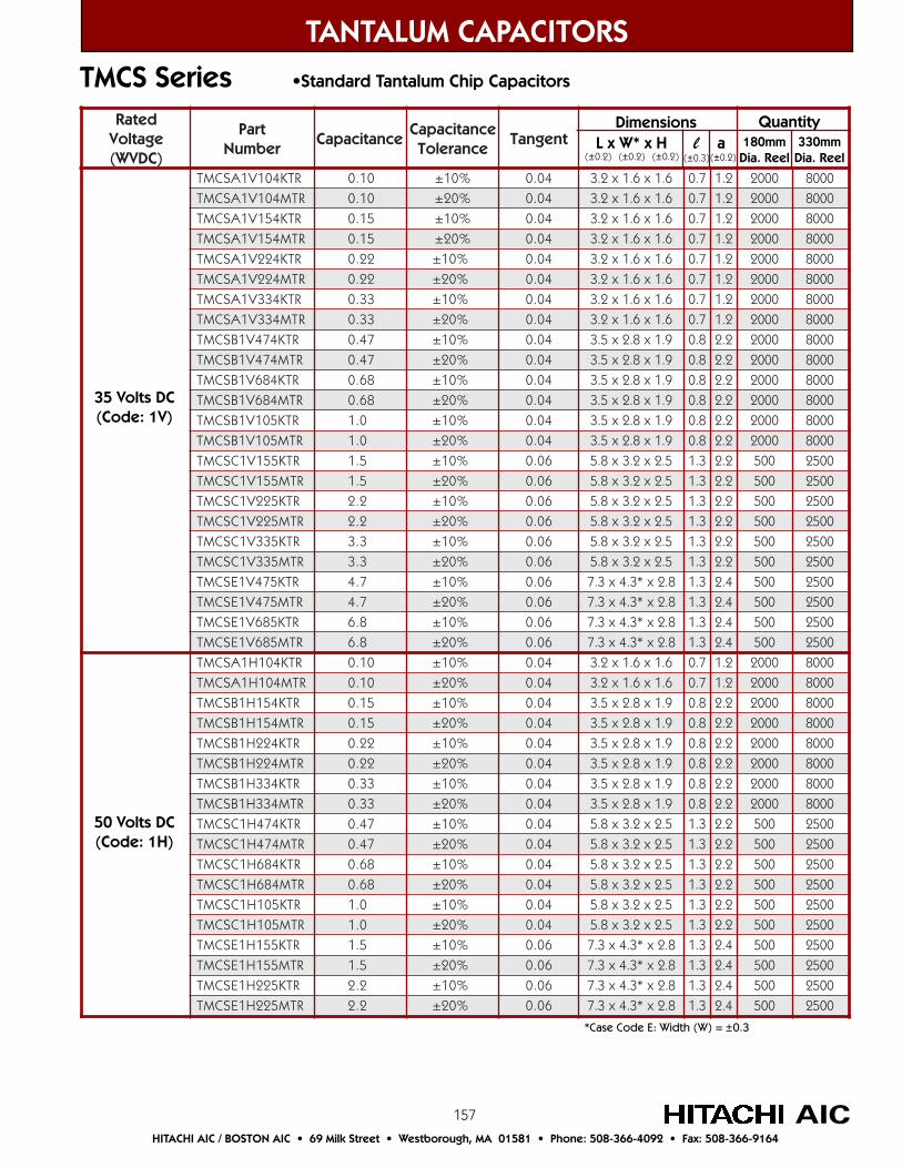
157
TANTALUM CAPACITORS
AICHITACHI AIC / BOSTON AIC • 69 Milk Street • Westborough, MA 01581 • Phone: 508-366-4092 • Fax: 508-366-9164
TMCS Series •Standard Tantalum Chip Capacitors
detaRegatloV)CDVW(
traPrebmuN
ecnaticapaCecnaticapaC
ecnareloTtnegnaT
RTK401V1ASCMT 01.0 %01± 40.0 6.1x6.1x2.3 7.0 2.1 0002 0008
RTM401V1ASCMT 01.0 %02± 40.0 6.1x6.1x2.3 7.0 2.1 0002 0008
RTK451V1ASCMT 51.0 %01± 40.0 6.1x6.1x2.3 7.0 2.1 0002 0008
RTM451V1ASCMT 51.0 %02± 40.0 6.1x6.1x2.3 7.0 2.1 0002 0008
RTK422V1ASCMT 22.0 %01± 40.0 6.1x6.1x2.3 7.0 2.1 0002 0008
RTM422V1ASCMT 22.0 %02± 40.0 6.1x6.1x2.3 7.0 2.1 0002 0008
RTK433V1ASCMT 33.0 %01± 40.0 6.1x6.1x2.3 7.0 2.1 0002 0008
RTM433V1ASCMT 33.0 %02± 40.0 6.1x6.1x2.3 7.0 2.1 0002 0008
RTK474V1BSCMT 74.0 %01± 40.0 9.1x8.2x5.3 8.0 2.2 0002 0008
RTM474V1BSCMT 74.0 %02± 40.0 9.1x8.2x5.3 8.0 2.2 0002 0008
RTK486V1BSCMT 86.0 %01± 40.0 9.1x8.2x5.3 8.0 2.2 0002 0008
RTM486V1BSCMT 86.0 %02± 40.0 9.1x8.2x5.3 8.0 2.2 0002 0008
RTK501V1BSCMT 0.1 %01± 40.0 9.1x8.2x5.3 8.0 2.2 0002 0008
RTM501V1BSCMT 0.1 %02± 40.0 9.1x8.2x5.3 8.0 2.2 0002 0008
RTK551V1CSCMT 5.1 %01± 60.0 5.2x2.3x8.5 3.1 2.2 005 0052
RTM551V1CSCMT 5.1 %02± 60.0 5.2x2.3x8.5 3.1 2.2 005 0052
RTK522V1CSCMT 2.2 %01± 60.0 5.2x2.3x8.5 3.1 2.2 005 0052
RTM522V1CSCMT 2.2 %02± 60.0 5.2x2.3x8.5 3.1 2.2 005 0052
RTK533V1CSCMT 3.3 %01± 60.0 5.2x2.3x8.5 3.1 2.2 005 0052
RTM533V1CSCMT 3.3 %02± 60.0 5.2x2.3x8.5 3.1 2.2 005 0052
RTK574V1ESCMT 7.4 %01± 60.0 8.2x*3.4x3.7 3.1 4.2 005 0052
RTM574V1ESCMT 7.4 %02± 60.0 8.2x*3.4x3.7 3.1 4.2 005 0052
RTK586V1ESCMT 8.6 %01± 60.0 8.2x*3.4x3.7 3.1 4.2 005 0052
RTM586V1ESCMT 8.6 %02± 60.0 8.2x*3.4x3.7 3.1 4.2 005 0052
RTK401H1ASCMT 01.0 %01± 40.0 6.1x6.1x2.3 7.0 2.1 0002 0008
RTM401H1ASCMT 01.0 %02± 40.0 6.1x6.1x2.3 7.0 2.1 0002 0008
RTK451H1BSCMT 51.0 %01± 40.0 9.1x8.2x5.3 8.0 2.2 0002 0008
RTM451H1BSCMT 51.0 %02± 40.0 9.1x8.2x5.3 8.0 2.2 0002 0008
RTK422H1BSCMT 22.0 %01± 40.0 9.1x8.2x5.3 8.0 2.2 0002 0008
RTM422H1BSCMT 22.0 %02± 40.0 9.1x8.2x5.3 8.0 2.2 0002 0008
RTK433H1BSCMT 33.0 %01± 40.0 9.1x8.2x5.3 8.0 2.2 0002 0008
RTM433H1BSCMT 33.0 %02± 40.0 9.1x8.2x5.3 8.0 2.2 0002 0008
RTK474H1CSCMT 74.0 %01± 40.0 5.2x2.3x8.5 3.1 2.2 005 0052
RTM474H1CSCMT 74.0 %02± 40.0 5.2x2.3x8.5 3.1 2.2 005 0052
RTK486H1CSCMT 86.0 %01± 40.0 5.2x2.3x8.5 3.1 2.2 005 0052
RTM486H1CSCMT 86.0 %02± 40.0 5.2x2.3x8.5 3.1 2.2 005 0052
RTK501H1CSCMT 0.1 %01± 40.0 5.2x2.3x8.5 3.1 2.2 005 0052
RTM501H1CSCMT 0.1 %02± 40.0 5.2x2.3x8.5 3.1 2.2 005 0052
RTK551H1ESCMT 5.1 %01± 60.0 8.2x*3.4x3.7 3.1 4.2 005 0052
RTM551H1ESCMT 5.1 %02± 60.0 8.2x*3.4x3.7 3.1 4.2 005 0052
RTK522H1ESCMT 2.2 %01± 60.0 8.2x*3.4x3.7 3.1 4.2 005 0052
RTM522H1ESCMT 2.2 %02± 60.0 8.2x*3.4x3.7 3.1 4.2 005 0052
*Case Code E: Width (W) = ±0.3
Dimensions L x W* x H l a(±0.2) (±0.2) (±0.2) (±0.3) (±0.2)
Quantity180mm
Dia. Reel330mm
Dia. Reel
50 Volts DC(Code: 1H)
35 Volts DC(Code: 1V)
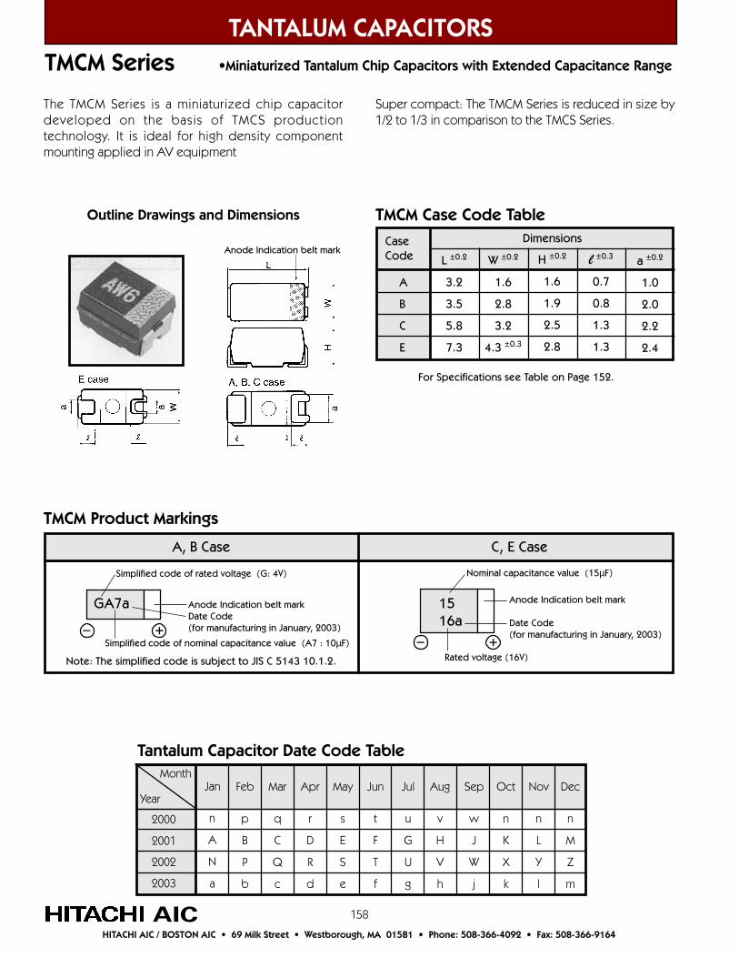
158
TANTALUM CAPACITORS
AICHITACHI AIC / BOSTON AIC • 69 Milk Street • Westborough, MA 01581 • Phone: 508-366-4092 • Fax: 508-366-9164
TMCM Series •Miniaturized Tantalum Chip Capacitors with Extended Capacitance Range
The TMCM Series is a miniaturized chip capacitordeveloped on the basis of TMCS productiontechnology. It is ideal for high density componentmounting applied in AV equipment
Super compact: The TMCM Series is reduced in size by1/2 to 1/3 in comparison to the TMCS Series.
Jan
n
A
N
a
Feb
p
B
P
b
Mar
q
C
Q
c
Sep
w
J
W
j
Aug
v
H
V
h
Jul
u
G
U
g
Jun
t
F
T
f
May
s
E
S
e
Apr
r
D
R
d
Dec
n
M
Z
m
Nov
n
L
Y
l
Oct
n
K
X
k
Month
Year
2000
2001
2002
2003
Tantalum Capacitor Date Code Table
A, B Case C, E Case
Simplified code of rated voltage (G: 4V)
+–
Note: The simplified code is subject to JIS C 5143 10.1.2.
GA7a Anode Indication belt markDate Code(for manufacturing in January, 2003)
1516a
Nominal capacitance value (15µF)
Anode Indication belt mark
Date Code(for manufacturing in January, 2003)
+–Rated voltage (16V)
TMCM Product Markings
Outline Drawings and Dimensions
Anode Indication belt mark
For Specifications see Table on Page 152.
TMCM Case Code Table
CaseCode
A
B
C
E
L ±0.2
3.2
3.5
5.8
7.3
Dimensions
W ±0.2
1.6
2.8
3.2
4.3 ±0.3
H ±0.2
1.6
1.9
2.5
2.8
l ±0.3
0.7
0.8
1.3
1.3
a ±0.2
1.0
2.0
2.2
2.4
Simplified code of nominal capacitance value (A7 : 10µF)
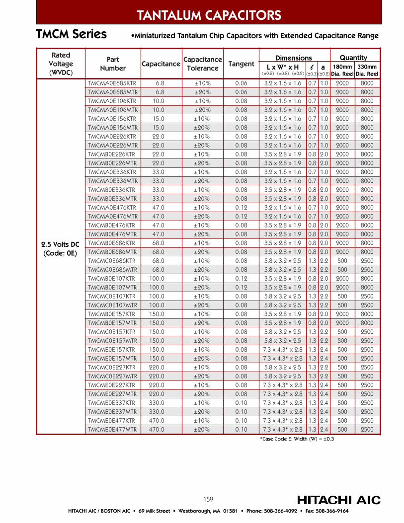
159
TANTALUM CAPACITORS
AICHITACHI AIC / BOSTON AIC • 69 Milk Street • Westborough, MA 01581 • Phone: 508-366-4092 • Fax: 508-366-9164
TMCM Series •Miniaturized Tantalum Chip Capacitors with Extended Capacitance Range
detaRegatloV)CDVW(
traPrebmuN
ecnaticapaCecnaticapaC
ecnareloTtnegnaT
RTK586E0AMCMT 8.6 %01± 60.0 6.1x6.1x2.3 7.0 0.1 0002 0008RTM586E0AMCMT 8.6 %02± 60.0 6.1x6.1x2.3 7.0 0.1 0002 0008
RTK601E0AMCMT 0.01 %01± 80.0 6.1x6.1x2.3 7.0 0.1 0002 0008RTM601E0AMCMT 0.01 %02± 80.0 6.1x6.1x2.3 7.0 0.1 0002 0008
RTK651E0AMCMT 0.51 %01± 80.0 6.1x6.1x2.3 7.0 0.1 0002 0008RTM651E0AMCMT 0.51 %02± 80.0 6.1x6.1x2.3 7.0 0.1 0002 0008
RTK622E0AMCMT 0.22 %01± 80.0 6.1x6.1x2.3 7.0 0.1 0002 0008RTM622E0AMCMT 0.22 %02± 80.0 6.1x6.1x2.3 7.0 0.1 0002 0008
RTK622E0BMCMT 0.22 %01± 80.0 9.1x8.2x5.3 8.0 0.2 0002 0008RTM622E0BMCMT 0.22 %02± 80.0 9.1x8.2x5.3 8.0 0.2 0002 0008RTK633E0AMCMT 0.33 %01± 80.0 6.1x6.1x2.3 7.0 0.1 0002 0008RTM633E0AMCMT 0.33 %02± 80.0 6.1x6.1x2.3 7.0 0.1 0002 0008
RTK633E0BMCMT 0.33 %01± 80.0 9.1x8.2x5.3 8.0 0.2 0002 0008RTM633E0BMCMT 0.33 %02± 80.0 9.1x8.2x5.3 8.0 0.2 0002 0008RTK674E0AMCMT 0.74 %01± 21.0 6.1x6.1x2.3 7.0 0.1 0002 0008RTM674E0AMCMT 0.74 %02± 21.0 6.1x6.1x2.3 7.0 0.1 0002 0008
RTK674E0BMCMT 0.74 %01± 80.0 9.1x8.2x5.3 8.0 0.2 0002 0008RTM674E0BMCMT 0.74 %02± 80.0 9.1x8.2x5.3 8.0 0.2 0002 0008
RTK686E0BMCMT 0.86 %01± 80.0 9.1x8.2x5.3 8.0 0.2 0002 0008RTM686E0BMCMT 0.86 %02± 80.0 9.1x8.2x5.3 8.0 0.2 0002 0008RTK686E0CMCMT 0.86 %01± 80.0 5.2x2.3x8.5 3.1 2.2 005 0052RTM686E0CMCMT 0.86 %02± 80.0 5.2x2.3x8.5 3.1 2.2 005 0052
RTK701E0BMCMT 0.001 %01± 21.0 9.1x8.2x5.3 8.0 0.2 0002 0008RTM701E0BMCMT 0.001 %02± 21.0 9.1x8.2x5.3 8.0 0.2 0002 0008RTK701E0CMCMT 0.001 %01± 80.0 5.2x2.3x8.5 3.1 2.2 005 0052RTM701E0CMCMT 0.001 %02± 80.0 5.2x2.3x8.5 3.1 2.2 005 0052
RTK751E0BMCMT 0.051 %01± 80.0 9.1x8.2x5.3 8.0 0.2 0002 0008RTM751E0BMCMT 0.051 %02± 80.0 9.1x8.2x5.3 8.0 0.2 0002 0008RTK751E0CMCMT 0.051 %01± 80.0 5.2x2.3x8.5 3.1 2.2 005 0052RTM751E0CMCMT 0.051 %02± 80.0 5.2x2.3x8.5 3.1 2.2 005 0052
RTK751E0EMCMT 0.051 %01± 80.0 8.2x*3.4x3.7 3.1 4.2 005 0052RTM751E0EMCMT 0.051 %02± 80.0 8.2x*3.4x3.7 3.1 4.2 005 0052RTK722E0CMCMT 0.022 %01± 80.0 5.2x2.3x8.5 3.1 2.2 005 0052RTM722E0CMCMT 0.022 %02± 80.0 5.2x2.3x8.5 3.1 2.2 005 0052
RTK722E0EMCMT 0.022 %01± 80.0 8.2x*3.4x3.7 3.1 4.2 005 0052RTM722E0EMCMT 0.022 %02± 80.0 8.2x*3.4x3.7 3.1 4.2 005 0052
RTK733E0EMCMT 0.033 %01± 01.0 8.2x*3.4x3.7 3.1 4.2 005 0052RTM733E0EMCMT 0.033 %02± 01.0 8.2x*3.4x3.7 3.1 4.2 005 0052
RTK774E0EMCMT 0.074 %01± 01.0 8.2x*3.4x3.7 3.1 4.2 005 0052RTM774E0EMCMT 0.074 %02± 01.0 8.2x*3.4x3.7 3.1 4.2 005 0052
2.5 Volts DC(Code: 0E)
Dimensions L x W* x H l a(±0.2) (±0.2) (±0.2) (±0.3) (±0.2)
Quantity180mm
Dia. Reel330mm
Dia. Reel
*Case Code E: Width (W) = ±0.3
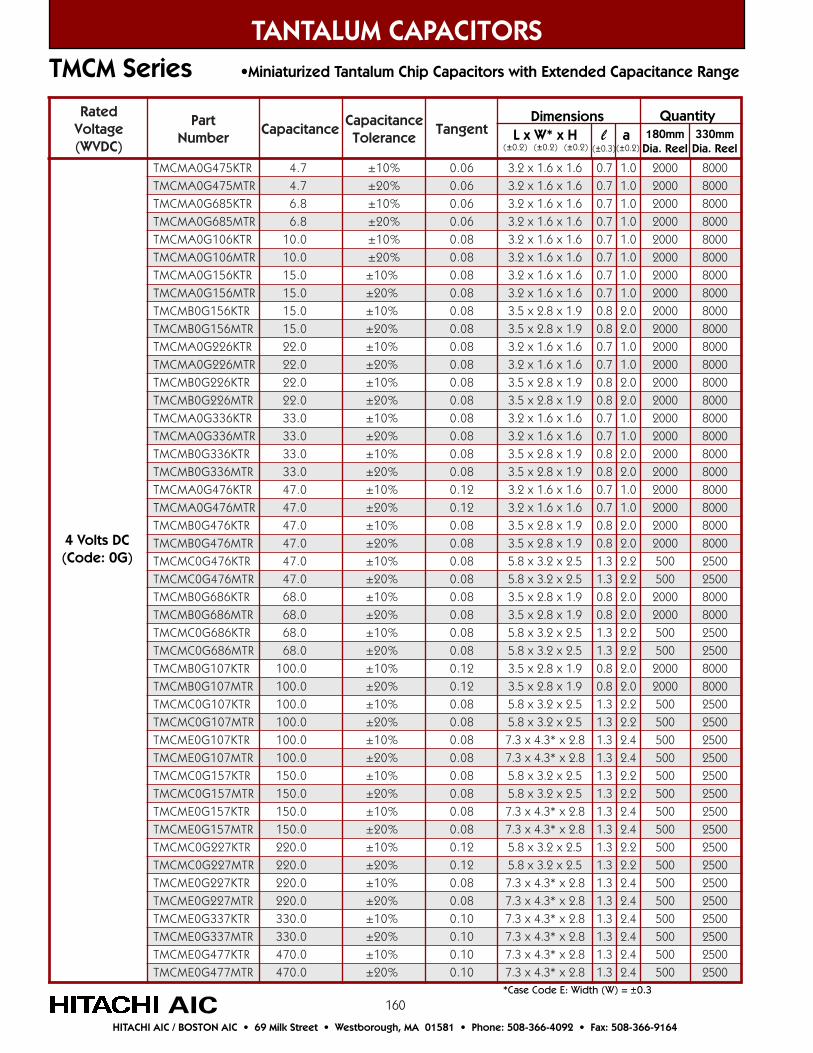
160
detaRegatloV)CDVW(
traPrebmuN
ecnaticapaCecnaticapaC
ecnareloTtnegnaT
RTK574G0AMCMT 7.4 %01± 60.0 6.1x6.1x2.3 7.0 0.1 0002 0008RTM574G0AMCMT 7.4 %02± 60.0 6.1x6.1x2.3 7.0 0.1 0002 0008
RTK586G0AMCMT 8.6 %01± 60.0 6.1x6.1x2.3 7.0 0.1 0002 0008RTM586G0AMCMT 8.6 %02± 60.0 6.1x6.1x2.3 7.0 0.1 0002 0008
RTK601G0AMCMT 0.01 %01± 80.0 6.1x6.1x2.3 7.0 0.1 0002 0008RTM601G0AMCMT 0.01 %02± 80.0 6.1x6.1x2.3 7.0 0.1 0002 0008
RTK651G0AMCMT 0.51 %01± 80.0 6.1x6.1x2.3 7.0 0.1 0002 0008RTM651G0AMCMT 0.51 %02± 80.0 6.1x6.1x2.3 7.0 0.1 0002 0008
RTK651G0BMCMT 0.51 %01± 80.0 9.1x8.2x5.3 8.0 0.2 0002 0008RTM651G0BMCMT 0.51 %02± 80.0 9.1x8.2x5.3 8.0 0.2 0002 0008RTK622G0AMCMT 0.22 %01± 80.0 6.1x6.1x2.3 7.0 0.1 0002 0008RTM622G0AMCMT 0.22 %02± 80.0 6.1x6.1x2.3 7.0 0.1 0002 0008
RTK622G0BMCMT 0.22 %01± 80.0 9.1x8.2x5.3 8.0 0.2 0002 0008RTM622G0BMCMT 0.22 %02± 80.0 9.1x8.2x5.3 8.0 0.2 0002 0008RTK633G0AMCMT 0.33 %01± 80.0 6.1x6.1x2.3 7.0 0.1 0002 0008RTM633G0AMCMT 0.33 %02± 80.0 6.1x6.1x2.3 7.0 0.1 0002 0008
RTK633G0BMCMT 0.33 %01± 80.0 9.1x8.2x5.3 8.0 0.2 0002 0008RTM633G0BMCMT 0.33 %02± 80.0 9.1x8.2x5.3 8.0 0.2 0002 0008RTK674G0AMCMT 0.74 %01± 21.0 6.1x6.1x2.3 7.0 0.1 0002 0008RTM674G0AMCMT 0.74 %02± 21.0 6.1x6.1x2.3 7.0 0.1 0002 0008
RTK674G0BMCMT 0.74 %01± 80.0 9.1x8.2x5.3 8.0 0.2 0002 0008RTM674G0BMCMT 0.74 %02± 80.0 9.1x8.2x5.3 8.0 0.2 0002 0008RTK674G0CMCMT 0.74 %01± 80.0 5.2x2.3x8.5 3.1 2.2 005 0052RTM674G0CMCMT 0.74 %02± 80.0 5.2x2.3x8.5 3.1 2.2 005 0052
RTK686G0BMCMT 0.86 %01± 80.0 9.1x8.2x5.3 8.0 0.2 0002 0008RTM686G0BMCMT 0.86 %02± 80.0 9.1x8.2x5.3 8.0 0.2 0002 0008RTK686G0CMCMT 0.86 %01± 80.0 5.2x2.3x8.5 3.1 2.2 005 0052RTM686G0CMCMT 0.86 %02± 80.0 5.2x2.3x8.5 3.1 2.2 005 0052
RTK701G0BMCMT 0.001 %01± 21.0 9.1x8.2x5.3 8.0 0.2 0002 0008RTM701G0BMCMT 0.001 %02± 21.0 9.1x8.2x5.3 8.0 0.2 0002 0008RTK701G0CMCMT 0.001 %01± 80.0 5.2x2.3x8.5 3.1 2.2 005 0052RTM701G0CMCMT 0.001 %02± 80.0 5.2x2.3x8.5 3.1 2.2 005 0052
RTK701G0EMCMT 0.001 %01± 80.0 8.2x*3.4x3.7 3.1 4.2 005 0052RTM701G0EMCMT 0.001 %02± 80.0 8.2x*3.4x3.7 3.1 4.2 005 0052RTK751G0CMCMT 0.051 %01± 80.0 5.2x2.3x8.5 3.1 2.2 005 0052RTM751G0CMCMT 0.051 %02± 80.0 5.2x2.3x8.5 3.1 2.2 005 0052
RTK751G0EMCMT 0.051 %01± 80.0 8.2x*3.4x3.7 3.1 4.2 005 0052RTM751G0EMCMT 0.051 %02± 80.0 8.2x*3.4x3.7 3.1 4.2 005 0052RTK722G0CMCMT 0.022 %01± 21.0 5.2x2.3x8.5 3.1 2.2 005 0052RTM722G0CMCMT 0.022 %02± 21.0 5.2x2.3x8.5 3.1 2.2 005 0052
RTK722G0EMCMT 0.022 %01± 80.0 8.2x*3.4x3.7 3.1 4.2 005 0052RTM722G0EMCMT 0.022 %02± 80.0 8.2x*3.4x3.7 3.1 4.2 005 0052
RTK733G0EMCMT 0.033 %01± 01.0 8.2x*3.4x3.7 3.1 4.2 005 0052RTM733G0EMCMT 0.033 %02± 01.0 8.2x*3.4x3.7 3.1 4.2 005 0052
RTK774G0EMCMT 0.074 %01± 01.0 8.2x*3.4x3.7 3.1 4.2 005 0052RTM774G0EMCMT 0.074 %02± 01.0 8.2x*3.4x3.7 3.1 4.2 005 0052
TANTALUM CAPACITORS
AICHITACHI AIC / BOSTON AIC • 69 Milk Street • Westborough, MA 01581 • Phone: 508-366-4092 • Fax: 508-366-9164
TMCM Series •Miniaturized Tantalum Chip Capacitors with Extended Capacitance Range
4 Volts DC(Code: 0G)
Dimensions L x W* x H l a(±0.2) (±0.2) (±0.2) (±0.3) (±0.2)
Quantity180mm
Dia. Reel330mm
Dia. Reel
*Case Code E: Width (W) = ±0.3
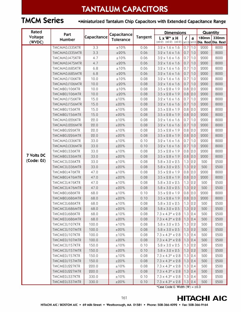
161
TANTALUM CAPACITORS
AICHITACHI AIC / BOSTON AIC • 69 Milk Street • Westborough, MA 01581 • Phone: 508-366-4092 • Fax: 508-366-9164
TMCM Series •Miniaturized Tantalum Chip Capacitors with Extended Capacitance Range
detaRegatloV)CDVW(
traPrebmuN
ecnaticapaCecnaticapaC
ecnareloTtnegnaT
RTK533J0AMCMT 3.3 %01± 60.0 6.1x6.1x2.3 7.0 0.1 0002 0008RTM533J0AMCMT 3.3 %02± 60.0 6.1x6.1x2.3 7.0 0.1 0002 0008
RTK574J0AMCMT 7.4 %01± 60.0 6.1x6.1x2.3 7.0 0.1 0002 0008RTM574J0AMCMT 7.4 %02± 60.0 6.1x6.1x2.3 7.0 0.1 0002 0008
RTK586J0AMCMT 8.6 %01± 60.0 6.1x6.1x2.3 7.0 0.1 0002 0008RTM586J0AMCMT 8.6 %02± 60.0 6.1x6.1x2.3 7.0 0.1 0002 0008
RTK601J0AMCMT 0.01 %01± 80.0 6.1x6.1x2.3 7.0 0.1 0002 0008RTM601J0AMCMT 0.01 %02± 80.0 6.1x6.1x2.3 7.0 0.1 0002 0008
RTK601J0BMCMT 0.01 %01± 80.0 9.1x8.2x5.3 8.0 0.2 0002 0008RTM601J0BMCMT 0.01 %02± 80.0 9.1x8.2x5.3 8.0 0.2 0002 0008RTK651J0AMCMT 0.51 %01± 80.0 6.1x6.1x2.3 7.0 0.1 0002 0008RTM651J0AMCMT 0.51 %02± 80.0 6.1x6.1x2.3 7.0 0.1 0002 0008
RTK651J0BMCMT 0.51 %01± 80.0 9.1x8.2x5.3 8.0 0.2 0002 0008RTM651J0BMCMT 0.51 %02± 80.0 9.1x8.2x5.3 8.0 0.2 0002 0008RTK622J0AMCMT 0.22 %01± 80.0 6.1x6.1x2.3 7.0 0.1 0002 0008RTM622J0AMCMT 0.22 %02± 80.0 6.1x6.1x2.3 7.0 0.1 0002 0008
RTK622J0BMCMT 0.22 %01± 80.0 9.1x8.2x5.3 8.0 0.2 0002 0008RTM622J0BMCMT 0.22 %02± 80.0 9.1x8.2x5.3 8.0 0.2 0002 0008RTK633J0AMCMT 0.33 %01± 01.0 6.1x6.1x2.3 7.0 0.1 0002 0008RTM633J0AMCMT 0.33 %02± 01.0 6.1x6.1x2.3 7.0 0.1 0002 0008
RTK633J0BMCMT 0.33 %01± 80.0 9.1x8.2x5.3 8.0 0.2 0002 0008RTM633J0BMCMT 0.33 %02± 80.0 9.1x8.2x5.3 8.0 0.2 0002 0008RTK633J0CMCMT 0.33 %01± 80.0 5.2x2.3x8.5 3.1 2.2 005 0052RTM633J0CMCMT 0.33 %02± 80.0 5.2x2.3x8.5 3.1 2.2 005 0052
RTK674J0BMCMT 0.74 %01± 80.0 9.1x8.2x5.3 8.0 0.2 0002 0008RTM674J0BMCMT 0.74 %02± 80.0 9.1x8.2x5.3 8.0 0.2 0002 0008RTK674J0CMCMT 0.74 %01± 80.0 5.2x2.3x8.5 3.1 2.2 005 0052RTM674J0CMCMT 0.74 %02± 80.0 5.2x2.3x8.5 3.1 2.2 005 0052
RTK686J0BMCMT 0.86 %01± 01.0 9.1x8.2x5.3 8.0 0.2 0002 0008RTM686J0BMCMT 0.86 %02± 01.0 9.1x8.2x5.3 8.0 0.2 0002 0008RTK686J0CMCMT 0.86 %01± 80.0 5.2x2.3x8.5 3.1 2.2 005 0052RTM686J0CMCMT 0.86 %02± 80.0 5.2x2.3x8.5 3.1 2.2 005 0052
RTK686J0EMCMT 0.86 %01± 80.0 8.2x*3.4x3.7 3.1 4.2 005 0052RTM686J0EMCMT 0.86 %02± 80.0 8.2x*3.4x3.7 3.1 4.2 005 0052RTK701J0CMCMT 0.001 %01± 80.0 5.2x2.3x8.5 3.1 2.2 005 0052RTM701J0CMCMT 0.001 %02± 80.0 5.2x2.3x8.5 3.1 2.2 005 0052
RTK701J0EMCMT 0.001 %01± 80.0 8.2x*3.4x3.7 3.1 4.2 005 0052RTM701J0EMCMT 0.001 %02± 80.0 8.2x*3.4x3.7 3.1 4.2 005 0052RTK751J0CMCMT 0.051 %01± 01.0 5.2x2.3x8.5 3.1 2.2 005 0052RTM751J0CMCMT 0.051 %02± 01.0 5.2x2.3x8.5 3.1 2.2 005 0052
RTK751J0EMCMT 0.051 %01± 80.0 8.2x*3.4x3.7 3.1 4.2 005 0052RTM751J0EMCMT 0.051 %02± 80.0 8.2x*3.4x3.7 3.1 4.2 005 0052
RTK722J0EMCMT 0.022 %01± 80.0 8.2x*3.4x3.7 3.1 4.2 005 0052RTM722J0EMCMT 0.022 %02± 80.0 8.2x*3.4x3.7 3.1 4.2 005 0052
RTK733J0EMCMT 0.033 %01± 01.0 8.2x*3.4x3.7 3.1 4.2 005 0052RTM733J0EMCMT 0.033 %02± 01.0 8.2x*3.4x3.7 3.1 4.2 005 0052
*Case Code E: Width (W) = ±0.3
7 Volts DC(Code: 0J)
Dimensions L x W* x H l a(±0.2) (±0.2) (±0.2) (±0.3) (±0.2)
Quantity180mm
Dia. Reel330mm
Dia. Reel
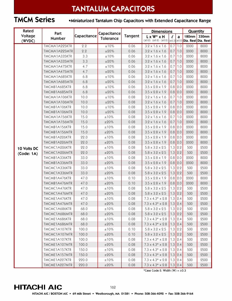
162
detaRegatloV)CDVW(
traPrebmuN
ecnaticapaCecnaticapaC
ecnareloTtnegnaT
RTK522A1AMCMT 2.2 %01± 60.0 6.1x6.1x2.3 7.0 0.1 0002 0008RTM522A1AMCMT 2.2 %02± 60.0 6.1x6.1x2.3 7.0 0.1 0002 0008
RTK533A1AMCMT 3.3 %01± 60.0 6.1x6.1x2.3 7.0 0.1 0002 0008RTM533A1AMCMT 3.3 %02± 60.0 6.1x6.1x2.3 7.0 0.1 0002 0008
RTK574A1AMCMT 7.4 %01± 60.0 6.1x6.1x2.3 7.0 0.1 0002 0008RTM574A1AMCMT 7.4 %02± 60.0 6.1x6.1x2.3 7.0 0.1 0002 0008
RTK586A1AMCMT 8.6 %01± 60.0 6.1x6.1x2.3 7.0 0.1 0002 0008RTM586A1AMCMT 8.6 %02± 60.0 6.1x6.1x2.3 7.0 0.1 0002 0008
RTK586A1BMCMT 8.6 %01± 60.0 9.1x8.2x5.3 8.0 0.2 0002 0008RTM586A1BMCMT 8.6 %02± 60.0 9.1x8.2x5.3 8.0 0.2 0002 0008RTK601A1AMCMT 0.01 %01± 80.0 6.1x6.1x2.3 7.0 0.1 0002 0008RTM601A1AMCMT 0.01 %02± 80.0 6.1x6.1x2.3 7.0 0.1 0002 0008
RTK601A1BMCMT 0.01 %01± 80.0 9.1x8.2x5.3 8.0 0.2 0002 0008RTM601A1BMCMT 0.01 %02± 80.0 9.1x8.2x5.3 8.0 0.2 0002 0008RTK651A1AMCMT 0.51 %01± 80.0 6.1x6.1x2.3 7.0 0.1 0002 0008RTM651A1AMCMT 0.51 %02± 80.0 6.1x6.1x2.3 7.0 0.1 0002 0008
RTK651A1BMCMT 0.51 %01± 80.0 9.1x8.2x5.3 8.0 0.2 0002 0008RTM651A1BMCMT 0.51 %02± 80.0 9.1x8.2x5.3 8.0 0.2 0002 0008
RTK622A1BMCMT 0.22 %01± 80.0 9.1x8.2x5.3 8.0 0.2 0002 0008RTM622A1BMCMT 0.22 %02± 80.0 9.1x8.2x5.3 8.0 0.2 0002 0008RTK622A1CMCMT 0.22 %01± 80.0 5.2x2.3x8.5 3.1 2.2 005 0052RTM622A1CMCMT 0.22 %02± 80.0 5.2x2.3x8.5 3.1 2.2 005 0052
RTK633A1BMCMT 0.33 %01± 80.0 9.1x8.2x5.3 8.0 0.2 0002 0008RTM633A1BMCMT 0.33 %02± 80.0 9.1x8.2x5.3 8.0 0.2 0002 0008RTK633A1CMCMT 0.33 %01± 80.0 5.2x2.3x8.5 3.1 2.2 005 0052RTM633A1CMCMT 0.33 %02± 80.0 5.2x2.3x8.5 3.1 2.2 005 0052
RTK674A1BMCMT 0.74 %01± 01.0 9.1x8.2x5.3 8.0 0.2 0002 0008RTM674A1BMCMT 0.74 %02± 01.0 9.1x8.2x5.3 8.0 0.2 0002 0008RTK674A1CMCMT 0.74 %01± 80.0 5.2x2.3x8.5 3.1 2.2 005 0052RTM674A1CMCMT 0.74 %02± 80.0 5.2x2.3x8.5 3.1 2.2 005 0052
RTK674A1EMCMT 0.74 %01± 80.0 8.2x*3.4x3.7 3.1 4.2 005 0052RTM674A1EMCMT 0.74 %02± 80.0 8.2x*3.4x3.7 3.1 4.2 005 0052RTK686A1CMCMT 0.86 %01± 80.0 5.2x2.3x8.5 3.1 2.2 005 0052RTM686A1CMCMT 0.86 %02± 80.0 5.2x2.3x8.5 3.1 2.2 005 0052
RTK686A1EMCMT 0.86 %01± 80.0 8.2x*3.4x3.7 3.1 4.2 005 0052RTM686A1EMCMT 0.86 %02± 80.0 8.2x*3.4x3.7 3.1 4.2 005 0052RTK701A1CMCMT 0.001 %01± 01.0 5.2x2.3x8.5 3.1 2.2 005 0052RTM701A1CMCMT 0.001 %02± 01.0 5.2x2.3x8.5 3.1 2.2 005 0052
RTK701A1EMCMT 0.001 %01± 80.0 8.2x*3.4x3.7 3.1 4.2 005 0052RTM701A1EMCMT 0.001 %02± 80.0 8.2x*3.4x3.7 3.1 4.2 005 0052
RTK751A1EMCMT 0.051 %01± 80.0 8.2x*3.4x3.7 3.1 4.2 005 0052RTM751A1EMCMT 0.051 %02± 80.0 8.2x*3.4x3.7 3.1 4.2 005 0052
RTK722A1EMCMT 0.022 %01± 80.0 8.2x*3.4x3.7 3.1 4.2 005 0052RTM722A1EMCMT 0.022 %02± 80.0 8.2x*3.4x3.7 3.1 4.2 005 0052
TANTALUM CAPACITORS
AICHITACHI AIC / BOSTON AIC • 69 Milk Street • Westborough, MA 01581 • Phone: 508-366-4092 • Fax: 508-366-9164
TMCM Series •Miniaturized Tantalum Chip Capacitors with Extended Capacitance Range
10 Volts DC(Code: 1A)
Dimensions L x W* x H l a(±0.2) (±0.2) (±0.2) (±0.3) (±0.2)
Quantity180mm
Dia. Reel330mm
Dia. Reel
*Case Code E: Width (W) = ±0.3
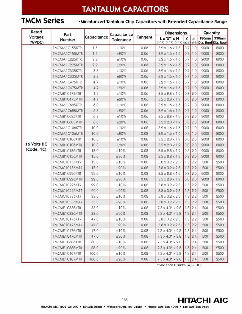
163
detaRegatloV)CDVW(
traPrebmuN
ecnaticapaCecnaticapaC
ecnareloTtnegnaT
RTK551C1AMCMT 5.1 %01± 60.0 6.1x6.1x2.3 7.0 0.1 0002 0008
RTM551C1AMCMT 5.1 %02± 60.0 6.1x6.1x2.3 7.0 0.1 0002 0008
RTK522C1AMCMT 2.2 %01± 60.0 6.1x6.1x2.3 7.0 0.1 0002 0008
RTM522C1AMCMT 2.2 %02± 60.0 6.1x6.1x2.3 7.0 0.1 0002 0008
RTK533C1AMCMT 3.3 %01± 60.0 6.1x6.1x2.3 7.0 0.1 0002 0008
RTM533C1AMCMT 3.3 %02± 60.0 6.1x6.1x2.3 7.0 0.1 0002 0008
RTK574C1AMCMT 7.4 %01± 60.0 6.1x6.1x2.3 7.0 0.1 0002 0008
RTM574C1AMCMT 7.4 %02± 60.0 6.1x6.1x2.3 7.0 0.1 0002 0008
RTK574C1BMCMT 7.4 %01± 60.0 9.1x8.2x5.3 8.0 0.2 0002 0008
RTM574C1BMCMT 7.4 %02± 60.0 9.1x8.2x5.3 8.0 0.2 0002 0008
RTK586C1AMCMT 8.6 %01± 60.0 6.1x6.1x2.3 7.0 0.1 0002 0008
RTM586C1AMCMT 8.6 %02± 60.0 6.1x6.1x2.3 7.0 0.1 0002 0008
RTK586C1BMCMT 8.6 %01± 60.0 9.1x8.2x5.3 8.0 0.2 0002 0008
RTM586C1BMCMT 8.6 %02± 60.0 9.1x8.2x5.3 8.0 0.2 0002 0008
RTK601C1AMCMT 0.01 %01± 80.0 6.1x6.1x2.3 7.0 0.1 0002 0008
RTM601C1AMCMT 0.01 %02± 80.0 6.1x6.1x2.3 7.0 0.1 0002 0008
RTK601C1BMCMT 0.01 %01± 80.0 9.1x8.2x5.3 8.0 0.2 0002 0008
RTM601C1BMCMT 0.01 %02± 80.0 9.1x8.2x5.3 8.0 0.2 0002 0008
RTK651C1BMCMT 0.51 %01± 80.0 9.1x8.2x5.3 8.0 0.2 0002 0008
RTM651C1BMCMT 0.51 %02± 80.0 9.1x8.2x5.3 8.0 0.2 0002 0008
RTK651C1CMCMT 0.51 %01± 80.0 5.2x2.3x8.5 3.1 2.2 005 0052
RTM651C1CMCMT 0.51 %02± 80.0 5.2x2.3x8.5 3.1 2.2 005 0052
RTK622C1BMCMT 0.22 %01± 80.0 9.1x8.2x5.3 8.0 0.2 0002 0008
RTM622C1BMCMT 0.22 %02± 80.0 9.1x8.2x5.3 8.0 0.2 0002 0008
RTK622C1CMCMT 0.22 %01± 80.0 5.2x2.3x8.5 3.1 2.2 005 0052
RTM622C1CMCMT 0.22 %02± 80.0 5.2x2.3x8.5 3.1 2.2 005 0052
RTK633C1CMCMT 0.33 %01± 80.0 5.2x2.3x8.5 3.1 2.2 005 0052
RTM633C1CMCMT 0.33 %02± 80.0 5.2x2.3x8.5 3.1 2.2 005 0052
RTK633C1EMCMT 0.33 %01± 80.0 8.2x*3.4x3.7 3.1 4.2 005 0052
RTM633C1EMCMT 0.33 %02± 80.0 8.2x*3.4x3.7 3.1 4.2 005 0052
RTK674C1CMCMT 0.74 %01± 80.0 5.2x2.3x8.5 3.1 2.2 005 0052
RTM674C1CMCMT 0.74 %02± 80.0 5.2x2.3x8.5 3.1 2.2 005 0052
RTK674C1EMCMT 0.74 %01± 80.0 8.2x*3.4x3.7 3.1 4.2 005 0052
RTM674C1EMCMT 0.74 %02± 80.0 8.2x*3.4x3.7 3.1 4.2 005 0052
RTK686C1EMCMT 0.86 %01± 80.0 8.2x*3.4x3.7 3.1 4.2 005 0052
RTM686C1EMCMT 0.86 %02± 80.0 8.2x*3.4x3.7 3.1 4.2 005 0052
RTK701C1EMCMT 0.001 %01± 80.0 8.2x*3.4x3.7 3.1 4.2 005 0052
RTM701C1EMCMT 0.001 %02± 80.0 8.2x*3.4x3.7 3.1 4.2 005 0052
TANTALUM CAPACITORS
AICHITACHI AIC / BOSTON AIC • 69 Milk Street • Westborough, MA 01581 • Phone: 508-366-4092 • Fax: 508-366-9164
TMCM Series •Miniaturized Tantalum Chip Capacitors with Extended Capacitance Range
*Case Code E: Width (W) = ±0.3
16 Volts DC(Code: 1C)
Dimensions L x W* x H l a(±0.2) (±0.2) (±0.2) (±0.3) (±0.2)
Quantity180mm
Dia. Reel330mm
Dia. Reel
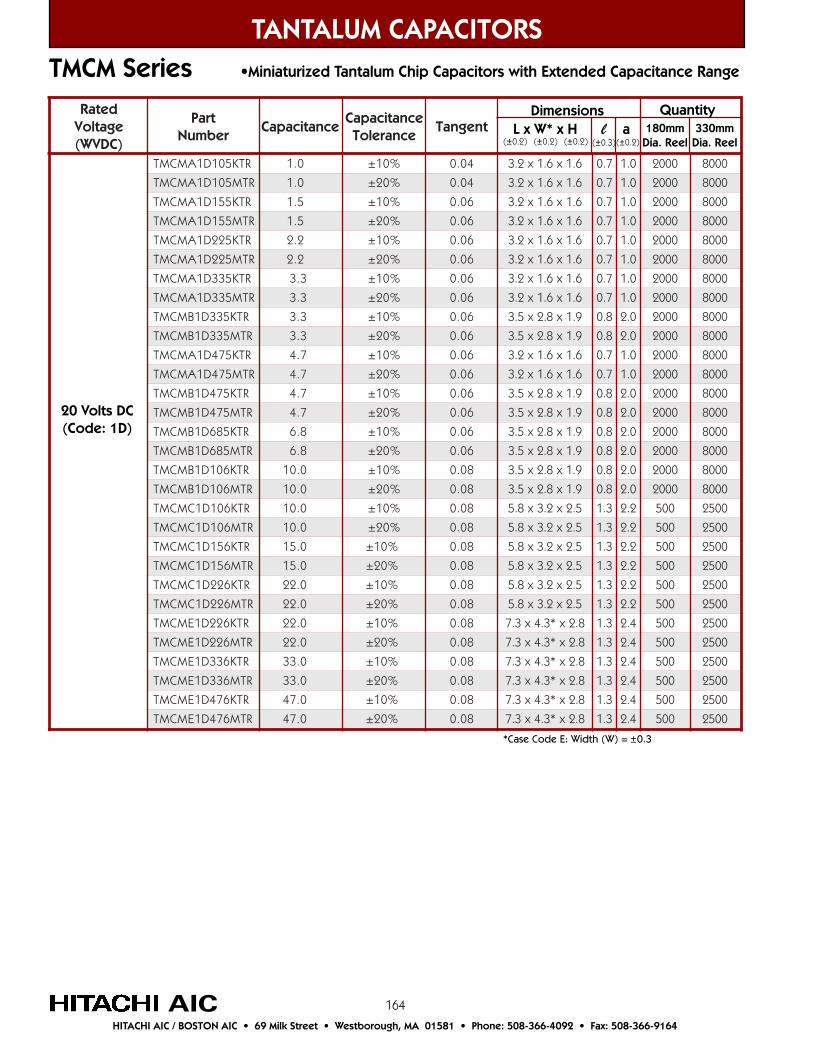
164
detaRegatloV)CDVW(
traPrebmuN
ecnaticapaCecnaticapaC
ecnareloTtnegnaT
RTK501D1AMCMT 0.1 %01± 40.0 6.1x6.1x2.3 7.0 0.1 0002 0008
RTM501D1AMCMT 0.1 %02± 40.0 6.1x6.1x2.3 7.0 0.1 0002 0008
RTK551D1AMCMT 5.1 %01± 60.0 6.1x6.1x2.3 7.0 0.1 0002 0008
RTM551D1AMCMT 5.1 %02± 60.0 6.1x6.1x2.3 7.0 0.1 0002 0008
RTK522D1AMCMT 2.2 %01± 60.0 6.1x6.1x2.3 7.0 0.1 0002 0008
RTM522D1AMCMT 2.2 %02± 60.0 6.1x6.1x2.3 7.0 0.1 0002 0008
RTK533D1AMCMT 3.3 %01± 60.0 6.1x6.1x2.3 7.0 0.1 0002 0008
RTM533D1AMCMT 3.3 %02± 60.0 6.1x6.1x2.3 7.0 0.1 0002 0008
RTK533D1BMCMT 3.3 %01± 60.0 9.1x8.2x5.3 8.0 0.2 0002 0008
RTM533D1BMCMT 3.3 %02± 60.0 9.1x8.2x5.3 8.0 0.2 0002 0008
RTK574D1AMCMT 7.4 %01± 60.0 6.1x6.1x2.3 7.0 0.1 0002 0008
RTM574D1AMCMT 7.4 %02± 60.0 6.1x6.1x2.3 7.0 0.1 0002 0008
RTK574D1BMCMT 7.4 %01± 60.0 9.1x8.2x5.3 8.0 0.2 0002 0008
RTM574D1BMCMT 7.4 %02± 60.0 9.1x8.2x5.3 8.0 0.2 0002 0008
RTK586D1BMCMT 8.6 %01± 60.0 9.1x8.2x5.3 8.0 0.2 0002 0008
RTM586D1BMCMT 8.6 %02± 60.0 9.1x8.2x5.3 8.0 0.2 0002 0008
RTK601D1BMCMT 0.01 %01± 80.0 9.1x8.2x5.3 8.0 0.2 0002 0008
RTM601D1BMCMT 0.01 %02± 80.0 9.1x8.2x5.3 8.0 0.2 0002 0008
RTK601D1CMCMT 0.01 %01± 80.0 5.2x2.3x8.5 3.1 2.2 005 0052
RTM601D1CMCMT 0.01 %02± 80.0 5.2x2.3x8.5 3.1 2.2 005 0052
RTK651D1CMCMT 0.51 %01± 80.0 5.2x2.3x8.5 3.1 2.2 005 0052
RTM651D1CMCMT 0.51 %02± 80.0 5.2x2.3x8.5 3.1 2.2 005 0052
RTK622D1CMCMT 0.22 %01± 80.0 5.2x2.3x8.5 3.1 2.2 005 0052
RTM622D1CMCMT 0.22 %02± 80.0 5.2x2.3x8.5 3.1 2.2 005 0052
RTK622D1EMCMT 0.22 %01± 80.0 8.2x*3.4x3.7 3.1 4.2 005 0052
RTM622D1EMCMT 0.22 %02± 80.0 8.2x*3.4x3.7 3.1 4.2 005 0052
RTK633D1EMCMT 0.33 %01± 80.0 8.2x*3.4x3.7 3.1 4.2 005 0052
RTM633D1EMCMT 0.33 %02± 80.0 8.2x*3.4x3.7 3.1 4.2 005 0052
RTK674D1EMCMT 0.74 %01± 80.0 8.2x*3.4x3.7 3.1 4.2 005 0052
RTM674D1EMCMT 0.74 %02± 80.0 8.2x*3.4x3.7 3.1 4.2 005 0052
TANTALUM CAPACITORS
AICHITACHI AIC / BOSTON AIC • 69 Milk Street • Westborough, MA 01581 • Phone: 508-366-4092 • Fax: 508-366-9164
TMCM Series •Miniaturized Tantalum Chip Capacitors with Extended Capacitance Range
20 Volts DC(Code: 1D)
Dimensions L x W* x H l a(±0.2) (±0.2) (±0.2) (±0.3) (±0.2)
Quantity180mm
Dia. Reel330mm
Dia. Reel
*Case Code E: Width (W) = ±0.3
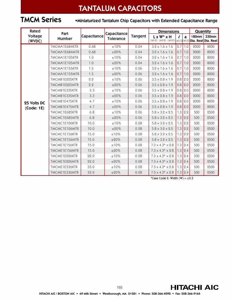
165
detaRegatloV)CDVW(
traPrebmuN
ecnaticapaCecnaticapaC
ecnareloTtnegnaT
RTK486E1AMCMT 86.0 %01± 40.0 6.1x6.1x2.3 7.0 0.1 0002 0008
RTM486E1AMCMT 86.0 %02± 40.0 6.1x6.1x2.3 7.0 0.1 0002 0008
RTK501E1AMCMT 0.1 %01± 40.0 6.1x6.1x2.3 7.0 0.1 0002 0008
RTM501E1AMCMT 0.1 %02± 40.0 6.1x6.1x2.3 7.0 0.1 0002 0008
RTK551E1AMCMT 5.1 %01± 60.0 6.1x6.1x2.3 7.0 0.1 0002 0008
RTM551E1AMCMT 5.1 %02± 60.0 6.1x6.1x2.3 7.0 0.1 0002 0008
RTK522E1BMCMT 2.2 %01± 60.0 9.1x8.2x5.3 8.0 0.2 0002 0008
RTM522E1BMCMT 2.2 %02± 60.0 9.1x8.2x5.3 8.0 0.2 0002 0008
RTK533E1BMCMT 3.3 %01± 60.0 9.1x8.2x5.3 8.0 0.2 0002 0008
RTM533E1BMCMT 3.3 %02± 60.0 9.1x8.2x5.3 8.0 0.2 0002 0008
RTK574E1BMCMT 7.4 %01± 60.0 9.1x8.2x5.3 8.0 0.2 0002 0008
RTM574E1BMCMT 7.4 %02± 60.0 9.1x8.2x5.3 8.0 0.2 0002 0008
RTK586E1CMCMT 8.6 %01± 60.0 5.2x2.3x8.5 3.1 2.2 005 0052
RTM586E1CMCMT 8.6 %02± 60.0 5.2x2.3x8.5 3.1 2.2 005 0052
RTK601E1CMCMT 0.01 %01± 80.0 5.2x2.3x8.5 3.1 2.2 005 0052
RTM601E1CMCMT 0.01 %02± 80.0 5.2x2.3x8.5 3.1 2.2 005 0052
RTK651E1CMCMT 0.51 %01± 80.0 5.2x2.3x8.5 3.1 2.2 005 0052
RTM651E1CMCMT 0.51 %02± 80.0 5.2x2.3x8.5 3.1 2.2 005 0052
RTK651E1EMCMT 0.51 %01± 80.0 8.2x*3.4x3.7 3.1 4.2 005 0052
RTM651E1EMCMT 0.51 %02± 80.0 8.2x*3.4x3.7 3.1 4.2 005 0052
RTK622E1EMCMT 0.22 %01± 80.0 8.2x*3.4x3.7 3.1 4.2 005 0052
RTM622E1EMCMT 0.22 %02± 80.0 8.2x*3.4x3.7 3.1 4.2 005 0052
RTK633E1EMCMT 0.33 %01± 80.0 8.2x*3.4x3.7 3.1 4.2 005 0052
RTM633E1EMCMT 0.33 %02± 80.0 8.2x*3.4x3.7 3.1 4.2 005 0052
TANTALUM CAPACITORS
AICHITACHI AIC / BOSTON AIC • 69 Milk Street • Westborough, MA 01581 • Phone: 508-366-4092 • Fax: 508-366-9164
TMCM Series •Miniaturized Tantalum Chip Capacitors with Extended Capacitance Range
*Case Code E: Width (W) = ±0.3
25 Volts DC(Code: 1E)
Dimensions L x W* x H l a(±0.2) (±0.2) (±0.2) (±0.3) (±0.2)
Quantity180mm
Dia. Reel330mm
Dia. Reel
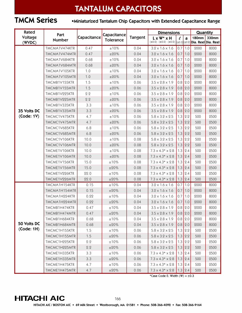
166
detaRegatloV)CDVW(
traPrebmuN
ecnaticapaCecnaticapaC
ecnareloTtnegnaT
RTK474V1AMCMT 74.0 %01± 40.0 6.1x6.1x2.3 7.0 0.1 0002 0008
RTM474V1AMCMT 74.0 %02± 40.0 6.1x6.1x2.3 7.0 0.1 0002 0008
RTK486V1AMCMT 86.0 %01± 40.0 6.1x6.1x2.3 7.0 0.1 0002 0008
RTM486V1AMCMT 86.0 %02± 40.0 6.1x6.1x2.3 7.0 0.1 0002 0008
RTK501V1AMCMT 0.1 %01± 40.0 6.1x6.1x2.3 7.0 0.1 0002 0008
RTM501V1AMCMT 0.1 %02± 40.0 6.1x6.1x2.3 7.0 0.1 0002 0008
RTK551V1BMCMT 5.1 %01± 60.0 9.1x8.2x5.3 8.0 0.2 0002 0008
RTM551V1BMCMT 5.1 %02± 60.0 9.1x8.2x5.3 8.0 0.2 0002 0008
RTK522V1BMCMT 2.2 %01± 60.0 9.1x8.2x5.3 8.0 0.2 0002 0008
RTM522V1BMCMT 2.2 %02± 60.0 9.1x8.2x5.3 8.0 0.2 0002 0008
RTK533V1BMCMT 3.3 %01± 60.0 9.1x8.2x5.3 8.0 0.2 0002 0008
RTM533V1BMCMT 3.3 %02± 60.0 9.1x8.2x5.3 8.0 0.2 0002 0008
RTK574V1CMCMT 7.4 %01± 60.0 5.2x2.3x8.5 3.1 2.2 005 0052
RTM574V1CMCMT 7.4 %02± 60.0 5.2x2.3x8.5 3.1 2.2 005 0052
RTK586V1CMCMT 8.6 %01± 60.0 5.2x2.3x8.5 3.1 2.2 005 0052
RTM586V1CMCMT 8.6 %02± 60.0 5.2x2.3x8.5 3.1 2.2 005 0052
RTK601V1CMCMT 0.01 %01± 80.0 5.2x2.3x8.5 3.1 2.2 005 0052
RTM601V1CMCMT 0.01 %02± 80.0 5.2x2.3x8.5 3.1 2.2 005 0052
RTK601V1EMCMT 0.01 %01± 80.0 8.2x*3.4x3.7 3.1 4.2 005 0052
RTM601V1EMCMT 0.01 %02± 80.0 8.2x*3.4x3.7 3.1 4.2 005 0052
RTK651V1EMCMT 0.51 %01± 80.0 8.2x*3.4x3.7 3.1 4.2 005 0052
RTM651V1EMCMT 0.51 %02± 80.0 8.2x*3.4x3.7 3.1 4.2 005 0052
RTK622V1EMCMT 0.22 %01± 80.0 8.2x*3.4x3.7 3.1 4.2 005 0052
RTM622V1EMCMT 0.22 %02± 80.0 8.2x*3.4x3.7 3.1 4.2 005 0052
RTK451H1AMCMT 51.0 %01± 40.0 6.1x6.1x2.3 7.0 0.1 0002 0008
RTM451H1AMCMT 51.0 %02± 40.0 6.1x6.1x2.3 7.0 0.1 0002 0008
RTK422H1AMCMT 22.0 %01± 40.0 6.1x6.1x2.3 7.0 0.1 0002 0008
RTM422H1AMCMT 22.0 %02± 40.0 6.1x6.1x2.3 7.0 0.1 0002 0008
RTK474H1BMCMT 74.0 %01± 40.0 9.1x8.2x5.3 8.0 0.2 0002 0008
RTM474H1BMCMT 74.0 %02± 40.0 9.1x8.2x5.3 8.0 0.2 0002 0008
RTK486H1BMCMT 86.0 %01± 40.0 9.1x8.2x5.3 8.0 0.2 0002 0008
RTM486H1BMCMT 86.0 %02± 40.0 9.1x8.2x5.3 8.0 0.2 0002 0008
RTK551H1CMCMT 5.1 %01± 60.0 5.2x2.3x8.5 3.1 2.2 005 0052
RTM551H1CMCMT 5.1 %02± 60.0 5.2x2.3x8.5 3.1 2.2 005 0052
RTK522H1CMCMT 2.2 %01± 60.0 5.2x2.3x8.5 3.1 2.2 005 0052
RTM522H1CMCMT 2.2 %02± 60.0 5.2x2.3x8.5 3.1 2.2 005 0052
RTK533H1EMCMT 3.3 %01± 60.0 8.2x*3.4x3.7 3.1 4.2 005 0052
RTM533H1EMCMT 3.3 %02± 60.0 8.2x*3.4x3.7 3.1 4.2 005 0052
RTK574H1EMCMT 7.4 %01± 60.0 8.2x*3.4x3.7 3.1 4.2 005 0052
RTM574H1EMCMT 7.4 %02± 60.0 8.2x*3.4x3.7 3.1 4.2 005 0052
TANTALUM CAPACITORS
AICHITACHI AIC / BOSTON AIC • 69 Milk Street • Westborough, MA 01581 • Phone: 508-366-4092 • Fax: 508-366-9164
TMCM Series •Miniaturized Tantalum Chip Capacitors with Extended Capacitance Range
35 Volts DC(Code: 1V)
Dimensions L x W* x H l a(±0.2) (±0.2) (±0.2) (±0.3) (±0.2)
Quantity180mm
Dia. Reel330mm
Dia. Reel
*Case Code E: Width (W) = ±0.3
50 Volts DC(Code: 1H)

167
TANTALUM CAPACITORS
AICHITACHI AIC / BOSTON AIC • 69 Milk Street • Westborough, MA 01581 • Phone: 508-366-4092 • Fax: 508-366-9164
TMCP Series •0805 Size Tantalum Chip Capacitors
The TMCP Series has been rendered even smaller due tothe accumulated technological knowhow inmanufacturing and production. It is now about 1/3 thecubic volume of the TMVS Series.
The TMCP is suitable fr high-density packaging essentialto Audio/Visual and other equipment downsizing
Jan
n
A
N
a
Feb
p
B
P
b
Mar
q
C
Q
c
Sep
w
J
W
j
Aug
v
H
V
h
Jul
u
G
U
g
Jun
t
F
T
f
May
s
E
S
e
Apr
r
D
R
d
Dec
n
M
Z
m
Nov
n
L
Y
l
Oct
n
K
X
k
Month
Year
2000
2001
2002
2003
Tantalum Capacitor Date Code Table
Outline Drawings and Dimensions
Anode Indication belt mark
For Specifications see Table on Page 152.
TMCP Case Code Table
CaseCode
P(0805)
L ±0.2
2.0
Dimensions
W ±0.2
1.25
H MAX
1.2
l ±0.2
0.5
a ±0.1
0.9
P Case Code (0805)
Simplified code of rated voltage (A : 10V)
+–
A 6Anode Indication belt mark
TMCM Product Markings
Simplified code of nominal capacitance (A6 : 1µF)
+–
A AAnode Indication belt mark
Simplified code of nominal capacitance (A : 1µF)
(Example 1)6.3V 1µF
(Example 2)10V 1µF
•When the capacitance code is the same, use the voltage code for higher rated voltage.
•When indicating both rated voltage and nominal capacitance by code, omit the multiplier of the capacitance code.
•The simplified code is subject to JIS C 5143, paragraph 10 and EIAJ RC-3813, paragraph 7.1.
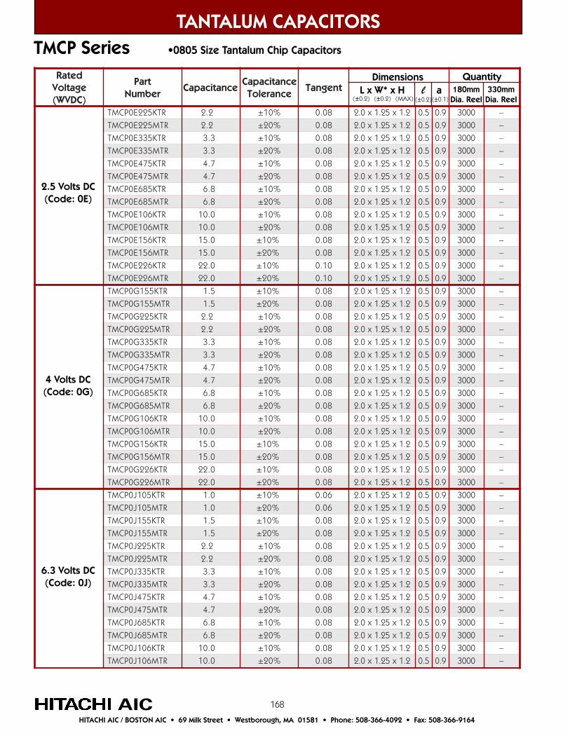
168
detaRegatloV)CDVW(
traPrebmuN
ecnaticapaCecnaticapaC
ecnareloTtnegnaT
RTK522E0PCMT 2.2 %01± 80.0 2.1x52.1x0.2 5.0 9.0 0003 –
RTM522E0PCMT 2.2 %02± 80.0 2.1x52.1x0.2 5.0 9.0 0003 –
RTK533E0PCMT 3.3 %01± 80.0 2.1x52.1x0.2 5.0 9.0 0003 –
RTM533E0PCMT 3.3 %02± 80.0 2.1x52.1x0.2 5.0 9.0 0003 –
RTK574E0PCMT 7.4 %01± 80.0 2.1x52.1x0.2 5.0 9.0 0003 –
RTM574E0PCMT 7.4 %02± 80.0 2.1x52.1x0.2 5.0 9.0 0003 –
RTK586E0PCMT 8.6 %01± 80.0 2.1x52.1x0.2 5.0 9.0 0003 –
RTM586E0PCMT 8.6 %02± 80.0 2.1x52.1x0.2 5.0 9.0 0003 –
RTK601E0PCMT 0.01 %01± 80.0 2.1x52.1x0.2 5.0 9.0 0003 –
RTM601E0PCMT 0.01 %02± 80.0 2.1x52.1x0.2 5.0 9.0 0003 –
RTK651E0PCMT 0.51 %01± 80.0 2.1x52.1x0.2 5.0 9.0 0003 –
RTM651E0PCMT 0.51 %02± 80.0 2.1x52.1x0.2 5.0 9.0 0003 –
RTK622E0PCMT 0.22 %01± 01.0 2.1x52.1x0.2 5.0 9.0 0003 –
RTM622E0PCMT 0.22 %02± 01.0 2.1x52.1x0.2 5.0 9.0 0003 –
RTK551G0PCMT 5.1 %01± 80.0 2.1x52.1x0.2 5.0 9.0 0003 –
RTM551G0PCMT 5.1 %02± 80.0 2.1x52.1x0.2 5.0 9.0 0003 –
RTK522G0PCMT 2.2 %01± 80.0 2.1x52.1x0.2 5.0 9.0 0003 –
RTM522G0PCMT 2.2 %02± 80.0 2.1x52.1x0.2 5.0 9.0 0003 –
RTK533G0PCMT 3.3 %01± 80.0 2.1x52.1x0.2 5.0 9.0 0003 –
RTM533G0PCMT 3.3 %02± 80.0 2.1x52.1x0.2 5.0 9.0 0003 –
RTK574G0PCMT 7.4 %01± 80.0 2.1x52.1x0.2 5.0 9.0 0003 –
RTM574G0PCMT 7.4 %02± 80.0 2.1x52.1x0.2 5.0 9.0 0003 –
RTK586G0PCMT 8.6 %01± 80.0 2.1x52.1x0.2 5.0 9.0 0003 –
RTM586G0PCMT 8.6 %02± 80.0 2.1x52.1x0.2 5.0 9.0 0003 –
RTK601G0PCMT 0.01 %01± 80.0 2.1x52.1x0.2 5.0 9.0 0003 –
RTM601G0PCMT 0.01 %02± 80.0 2.1x52.1x0.2 5.0 9.0 0003 –
RTK651G0PCMT 0.51 %01± 80.0 2.1x52.1x0.2 5.0 9.0 0003 –
RTM651G0PCMT 0.51 %02± 80.0 2.1x52.1x0.2 5.0 9.0 0003 –
RTK622G0PCMT 0.22 %01± 80.0 2.1x52.1x0.2 5.0 9.0 0003 –
RTM622G0PCMT 0.22 %02± 80.0 2.1x52.1x0.2 5.0 9.0 0003 –
RTK501J0PCMT 0.1 %01± 60.0 2.1x52.1x0.2 5.0 9.0 0003 –
RTM501J0PCMT 0.1 %02± 60.0 2.1x52.1x0.2 5.0 9.0 0003 –
RTK551J0PCMT 5.1 %01± 80.0 2.1x52.1x0.2 5.0 9.0 0003 –
RTM551J0PCMT 5.1 %02± 80.0 2.1x52.1x0.2 5.0 9.0 0003 –
RTK522J0PCMT 2.2 %01± 80.0 2.1x52.1x0.2 5.0 9.0 0003 –
RTM522J0PCMT 2.2 %02± 80.0 2.1x52.1x0.2 5.0 9.0 0003 –
RTK533J0PCMT 3.3 %01± 80.0 2.1x52.1x0.2 5.0 9.0 0003 –
RTM533J0PCMT 3.3 %02± 80.0 2.1x52.1x0.2 5.0 9.0 0003 –
RTK574J0PCMT 7.4 %01± 80.0 2.1x52.1x0.2 5.0 9.0 0003 –
RTM574J0PCMT 7.4 %02± 80.0 2.1x52.1x0.2 5.0 9.0 0003 –
RTK586J0PCMT 8.6 %01± 80.0 2.1x52.1x0.2 5.0 9.0 0003 –
RTM586J0PCMT 8.6 %02± 80.0 2.1x52.1x0.2 5.0 9.0 0003 –
RTK601J0PCMT 0.01 %01± 80.0 2.1x52.1x0.2 5.0 9.0 0003 –
RTM601J0PCMT 0.01 %02± 80.0 2.1x52.1x0.2 5.0 9.0 0003 –
TANTALUM CAPACITORS
AICHITACHI AIC / BOSTON AIC • 69 Milk Street • Westborough, MA 01581 • Phone: 508-366-4092 • Fax: 508-366-9164
2.5 Volts DC(Code: 0E)
Dimensions L x W* x H l a(±0.2) (±0.2) (MAX) (±0.2) (±0.1)
Quantity180mm
Dia. Reel330mm
Dia. Reel
TMCP Series •0805 Size Tantalum Chip Capacitors
4 Volts DC(Code: 0G)
6.3 Volts DC(Code: 0J)
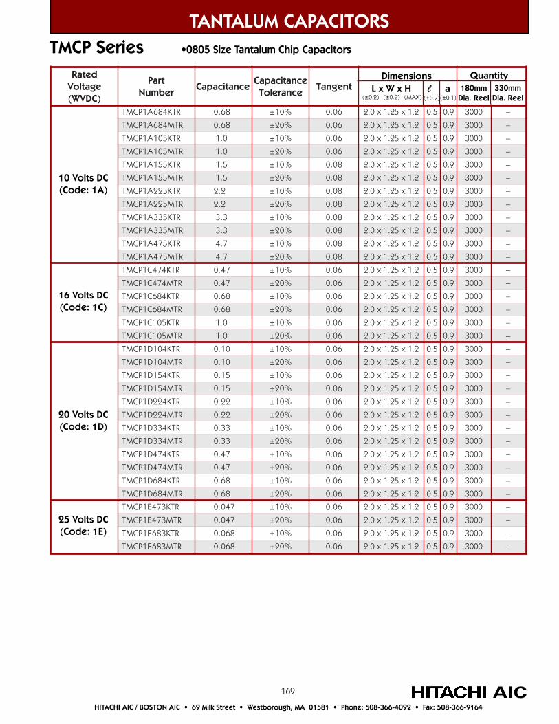
169
TANTALUM CAPACITORS
AICHITACHI AIC / BOSTON AIC • 69 Milk Street • Westborough, MA 01581 • Phone: 508-366-4092 • Fax: 508-366-9164
TMCP Series •0805 Size Tantalum Chip Capacitors
detaRegatloV)CDVW(
traPrebmuN
ecnaticapaCecnaticapaC
ecnareloTtnegnaT
RTK486A1PCMT 86.0 %01± 60.0 2.1x52.1x0.2 5.0 9.0 0003 –
RTM486A1PCMT 86.0 %02± 60.0 2.1x52.1x0.2 5.0 9.0 0003 –
RTK501A1PCMT 0.1 %01± 60.0 2.1x52.1x0.2 5.0 9.0 0003 –
RTM501A1PCMT 0.1 %02± 60.0 2.1x52.1x0.2 5.0 9.0 0003 –
RTK551A1PCMT 5.1 %01± 80.0 2.1x52.1x0.2 5.0 9.0 0003 –
RTM551A1PCMT 5.1 %02± 80.0 2.1x52.1x0.2 5.0 9.0 0003 –
RTK522A1PCMT 2.2 %01± 80.0 2.1x52.1x0.2 5.0 9.0 0003 –
RTM522A1PCMT 2.2 %02± 80.0 2.1x52.1x0.2 5.0 9.0 0003 –
RTK533A1PCMT 3.3 %01± 80.0 2.1x52.1x0.2 5.0 9.0 0003 –
RTM533A1PCMT 3.3 %02± 80.0 2.1x52.1x0.2 5.0 9.0 0003 –
RTK574A1PCMT 7.4 %01± 80.0 2.1x52.1x0.2 5.0 9.0 0003 –
RTM574A1PCMT 7.4 %02± 80.0 2.1x52.1x0.2 5.0 9.0 0003 –
RTK474C1PCMT 74.0 %01± 60.0 2.1x52.1x0.2 5.0 9.0 0003 –
RTM474C1PCMT 74.0 %02± 60.0 2.1x52.1x0.2 5.0 9.0 0003 –
RTK486C1PCMT 86.0 %01± 60.0 2.1x52.1x0.2 5.0 9.0 0003 –
RTM486C1PCMT 86.0 %02± 60.0 2.1x52.1x0.2 5.0 9.0 0003 –
RTK501C1PCMT 0.1 %01± 60.0 2.1x52.1x0.2 5.0 9.0 0003 –
RTM501C1PCMT 0.1 %02± 60.0 2.1x52.1x0.2 5.0 9.0 0003 –
RTK401D1PCMT 01.0 %01± 60.0 2.1x52.1x0.2 5.0 9.0 0003 –
RTM401D1PCMT 01.0 %02± 60.0 2.1x52.1x0.2 5.0 9.0 0003 –
RTK451D1PCMT 51.0 %01± 60.0 2.1x52.1x0.2 5.0 9.0 0003 –
RTM451D1PCMT 51.0 %02± 60.0 2.1x52.1x0.2 5.0 9.0 0003 –
RTK422D1PCMT 22.0 %01± 60.0 2.1x52.1x0.2 5.0 9.0 0003 –
RTM422D1PCMT 22.0 %02± 60.0 2.1x52.1x0.2 5.0 9.0 0003 –
RTK433D1PCMT 33.0 %01± 60.0 2.1x52.1x0.2 5.0 9.0 0003 –
RTM433D1PCMT 33.0 %02± 60.0 2.1x52.1x0.2 5.0 9.0 0003 –
RTK474D1PCMT 74.0 %01± 60.0 2.1x52.1x0.2 5.0 9.0 0003 –
RTM474D1PCMT 74.0 %02± 60.0 2.1x52.1x0.2 5.0 9.0 0003 –
RTK486D1PCMT 86.0 %01± 60.0 2.1x52.1x0.2 5.0 9.0 0003 –
RTM486D1PCMT 86.0 %02± 60.0 2.1x52.1x0.2 5.0 9.0 0003 –
RTK374E1PCMT 740.0 %01± 60.0 2.1x52.1x0.2 5.0 9.0 0003 –
RTM374E1PCMT 740.0 %02± 60.0 2.1x52.1x0.2 5.0 9.0 0003 –
RTK386E1PCMT 860.0 %01± 60.0 2.1x52.1x0.2 5.0 9.0 0003 –
RTM386E1PCMT 860.0 %02± 60.0 2.1x52.1x0.2 5.0 9.0 0003 –
20 Volts DC(Code: 1D)
10 Volts DC(Code: 1A)
16 Volts DC(Code: 1C)
25 Volts DC(Code: 1E)
Dimensions L x W x H l a(±0.2) (±0.2) (MAX) (±0.2) (±0.1)
Quantity180mm
Dia. Reel330mm
Dia. Reel
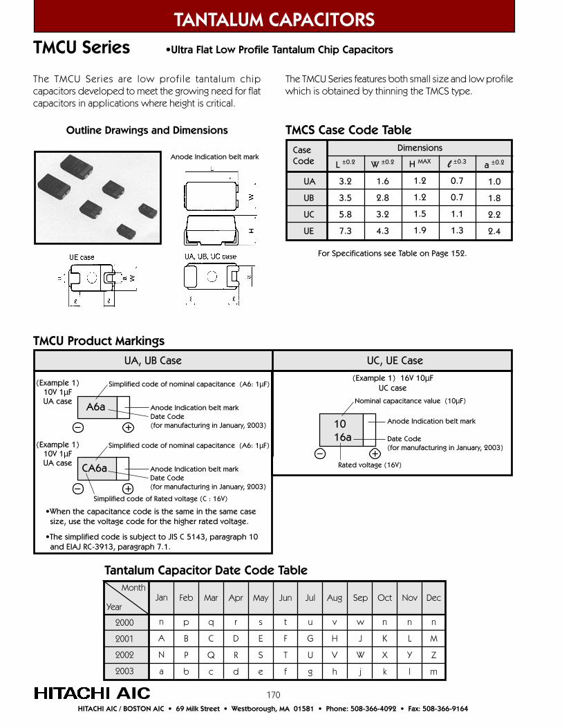
170
TANTALUM CAPACITORS
AICHITACHI AIC / BOSTON AIC • 69 Milk Street • Westborough, MA 01581 • Phone: 508-366-4092 • Fax: 508-366-9164
TMCU Series •Ultra Flat Low Profile Tantalum Chip Capacitors
The TMCU Series are low profile tantalum chipcapacitors developed to meet the growing need for flatcapacitors in applications where height is critical.
The TMCU Series features both small size and low profilewhich is obtained by thinning the TMCS type.
Jan
n
A
N
a
Feb
p
B
P
b
Mar
q
C
Q
c
Sep
w
J
W
j
Aug
v
H
V
h
Jul
u
G
U
g
Jun
t
F
T
f
May
s
E
S
e
Apr
r
D
R
d
Dec
n
M
Z
m
Nov
n
L
Y
l
Oct
n
K
X
k
Month
Year
2000
2001
2002
2003
Tantalum Capacitor Date Code Table
UA, UB Case UC, UE Case
Simplified code of nominal capacitance (A6: 1µF)
+–
•When the capacitance code is the same in the same case size, use the voltage code for the higher rated voltage.
•The simplified code is subject to JIS C 5143, paragraph 10 and EIAJ RC-3913, paragraph 7.1.
A6a Anode Indication belt markDate Code(for manufacturing in January, 2003) 10
16a
Nominal capacitance value (10µF)
Anode Indication belt mark
Date Code(for manufacturing in January, 2003)
+–Rated voltage (16V)
TMCU Product Markings
Outline Drawings and Dimensions
Anode Indication belt mark
For Specifications see Table on Page 152.
TMCS Case Code Table
CaseCode
UA
UB
UC
UE
L ±0.2
3.2
3.5
5.8
7.3
Dimensions
W ±0.2
1.6
2.8
3.2
4.3
H MAX
1.2
1.2
1.5
1.9
l ±0.3
0.7
0.7
1.1
1.3
a ±0.2
1.0
1.8
2.2
2.4
(Example 1) 16V 10µFUC case
Simplified code of nominal capacitance (A6: 1µF)
+–
CA6a Anode Indication belt markDate Code(for manufacturing in January, 2003)
(Example 1)10V 1µFUA case
(Example 1)10V 1µFUA case
Simplified code of Rated voltage (C : 16V)
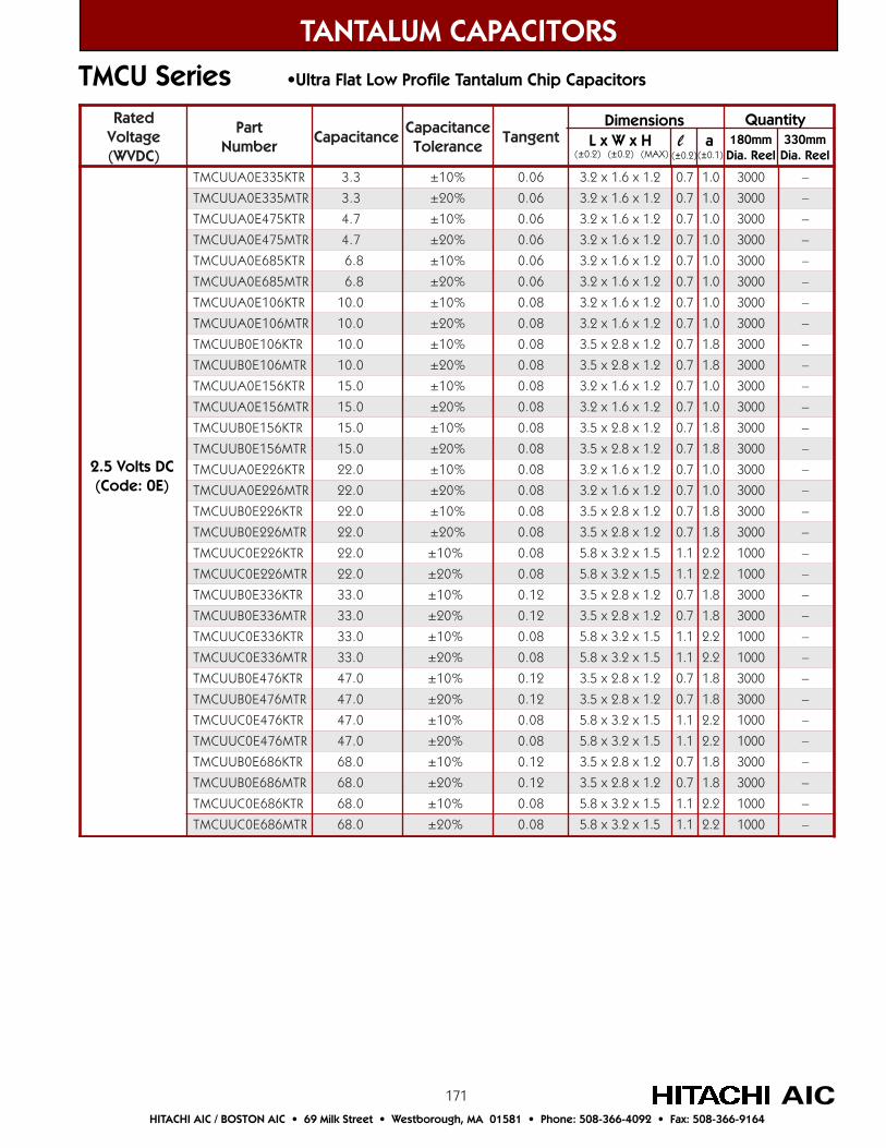
171
TANTALUM CAPACITORS
AICHITACHI AIC / BOSTON AIC • 69 Milk Street • Westborough, MA 01581 • Phone: 508-366-4092 • Fax: 508-366-9164
TMCU Series •Ultra Flat Low Profile Tantalum Chip Capacitors
detaRegatloV)CDVW(
traPrebmuN
ecnaticapaCecnaticapaC
ecnareloTtnegnaT
RTK533E0AUUCMT 3.3 %01± 60.0 2.1x6.1x2.3 7.0 0.1 0003 –
RTM533E0AUUCMT 3.3 %02± 60.0 2.1x6.1x2.3 7.0 0.1 0003 –
RTK574E0AUUCMT 7.4 %01± 60.0 2.1x6.1x2.3 7.0 0.1 0003 –
RTM574E0AUUCMT 7.4 %02± 60.0 2.1x6.1x2.3 7.0 0.1 0003 –
RTK586E0AUUCMT 8.6 %01± 60.0 2.1x6.1x2.3 7.0 0.1 0003 –
RTM586E0AUUCMT 8.6 %02± 60.0 2.1x6.1x2.3 7.0 0.1 0003 –
RTK601E0AUUCMT 0.01 %01± 80.0 2.1x6.1x2.3 7.0 0.1 0003 –
RTM601E0AUUCMT 0.01 %02± 80.0 2.1x6.1x2.3 7.0 0.1 0003 –
RTK601E0BUUCMT 0.01 %01± 80.0 2.1x8.2x5.3 7.0 8.1 0003 –
RTM601E0BUUCMT 0.01 %02± 80.0 2.1x8.2x5.3 7.0 8.1 0003 –
RTK651E0AUUCMT 0.51 %01± 80.0 2.1x6.1x2.3 7.0 0.1 0003 –
RTM651E0AUUCMT 0.51 %02± 80.0 2.1x6.1x2.3 7.0 0.1 0003 –
RTK651E0BUUCMT 0.51 %01± 80.0 2.1x8.2x5.3 7.0 8.1 0003 –
RTM651E0BUUCMT 0.51 %02± 80.0 2.1x8.2x5.3 7.0 8.1 0003 –
RTK622E0AUUCMT 0.22 %01± 80.0 2.1x6.1x2.3 7.0 0.1 0003 –
RTM622E0AUUCMT 0.22 %02± 80.0 2.1x6.1x2.3 7.0 0.1 0003 –
RTK622E0BUUCMT 0.22 %01± 80.0 2.1x8.2x5.3 7.0 8.1 0003 –
RTM622E0BUUCMT 0.22 %02± 80.0 2.1x8.2x5.3 7.0 8.1 0003 –
RTK622E0CUUCMT 0.22 %01± 80.0 5.1x2.3x8.5 1.1 2.2 0001 –
RTM622E0CUUCMT 0.22 %02± 80.0 5.1x2.3x8.5 1.1 2.2 0001 –
RTK633E0BUUCMT 0.33 %01± 21.0 2.1x8.2x5.3 7.0 8.1 0003 –
RTM633E0BUUCMT 0.33 %02± 21.0 2.1x8.2x5.3 7.0 8.1 0003 –
RTK633E0CUUCMT 0.33 %01± 80.0 5.1x2.3x8.5 1.1 2.2 0001 –
RTM633E0CUUCMT 0.33 %02± 80.0 5.1x2.3x8.5 1.1 2.2 0001 –
RTK674E0BUUCMT 0.74 %01± 21.0 2.1x8.2x5.3 7.0 8.1 0003 –
RTM674E0BUUCMT 0.74 %02± 21.0 2.1x8.2x5.3 7.0 8.1 0003 –
RTK674E0CUUCMT 0.74 %01± 80.0 5.1x2.3x8.5 1.1 2.2 0001 –
RTM674E0CUUCMT 0.74 %02± 80.0 5.1x2.3x8.5 1.1 2.2 0001 –
RTK686E0BUUCMT 0.86 %01± 21.0 2.1x8.2x5.3 7.0 8.1 0003 –
RTM686E0BUUCMT 0.86 %02± 21.0 2.1x8.2x5.3 7.0 8.1 0003 –
RTK686E0CUUCMT 0.86 %01± 80.0 5.1x2.3x8.5 1.1 2.2 0001 –
RTM686E0CUUCMT 0.86 %02± 80.0 5.1x2.3x8.5 1.1 2.2 0001 –
2.5 Volts DC(Code: 0E)
Dimensions L x W x H l a(±0.2) (±0.2) (MAX) (±0.2) (±0.1)
Quantity180mm
Dia. Reel330mm
Dia. Reel
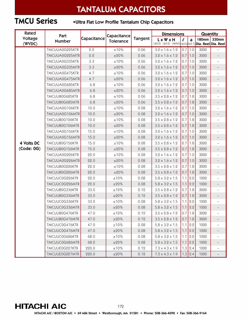
172
detaRegatloV)CDVW(
traPrebmuN
ecnaticapaCecnaticapaC
ecnareloTtnegnaT
RTK522G0AUUCMT 2.2 %01± 60.0 2.1x6.1x2.3 7.0 0.1 0003 –
RTM522G0AUUCMT 2.2 %02± 60.0 2.1x6.1x2.3 7.0 0.1 0003 –
RTK533G0AUUCMT 3.3 %01± 60.0 2.1x6.1x2.3 7.0 0.1 0003 –
RTM533G0AUUCMT 3.3 %02± 60.0 2.1x6.1x2.3 7.0 0.1 0003 –
RTK574G0AUUCMT 7.4 %01± 60.0 2.1x6.1x2.3 7.0 0.1 0003 –
RTM574G0AUUCMT 7.4 %02± 60.0 2.1x6.1x2.3 7.0 0.1 0003 –
RTK586G0AUUCMT 8.6 %01± 60.0 2.1x6.1x2.3 7.0 0.1 0003 –
RTM586G0AUUCMT 8.6 %02± 60.0 2.1x6.1x2.3 7.0 0.1 0003 –
RTK586G0BUUCMT 8.6 %01± 60.0 2.1x8.2x5.3 7.0 8.1 0003 –
RTM586G0BUUCMT 8.6 %02± 60.0 2.1x8.2x5.3 7.0 8.1 0003 –
RTK601G0AUUCMT 0.01 %01± 80.0 2.1x6.1x2.3 7.0 0.1 0003 –
RTM601G0AUUCMT 0.01 %02± 80.0 2.1x6.1x2.3 7.0 0.1 0003 –
RTK601G0BUUCMT 0.01 %01± 80.0 2.1x8.2x5.3 7.0 8.1 0003 –
RTM601G0BUUCMT 0.01 %02± 80.0 2.1x8.2x5.3 7.0 8.1 0003 –
RTK651G0AUUCMT 0.51 %01± 80.0 2.1x6.1x2.3 7.0 0.1 0003 –
RTM651G0AUUCMT 0.51 %02± 80.0 2.1x6.1x2.3 7.0 0.1 0003 –
RTK651G0BUUCMT 0.51 %01± 80.0 2.1x8.2x5.3 7.0 8.1 0003 –
RTM651G0BUUCMT 0.51 %02± 80.0 2.1x8.2x5.3 7.0 8.1 0003 –
RTK622G0AUUCMT 0.22 %01± 80.0 2.1x6.1x2.3 7.0 0.1 0003 –
RTM622G0AUUCMT 0.22 %02± 80.0 2.1x6.1x2.3 7.0 0.1 0003 –
RTK622G0BUUCMT 0.22 %01± 80.0 2.1x8.2x5.3 7.0 8.1 0003 –
RTM622G0BUUCMT 0.22 %02± 80.0 2.1x8.2x5.3 7.0 8.1 0003 –
RTK622G0CUUCMT 0.22 %01± 80.0 5.1x2.3x8.5 1.1 2.2 0001 –
RTM622G0CUUCMT 0.22 %02± 80.0 5.1x2.3x8.5 1.1 2.2 0001 –
RTK633G0BUUCMT 0.33 %01± 21.0 2.1x8.2x5.3 7.0 8.1 0003 –
RTM633G0BUUCMT 0.33 %02± 21.0 2.1x8.2x5.3 7.0 8.1 0003 –
RTK633G0CUUCMT 0.33 %01± 80.0 5.1x2.3x8.5 1.1 2.2 0001 –
RTM633G0CUUCMT 0.33 %02± 80.0 5.1x2.3x8.5 1.1 2.2 0001 –
RTK674G0BUUCMT 0.74 %01± 21.0 2.1x8.2x5.3 7.0 8.1 0003 –
RTM674G0BUUCMT 0.74 %02± 21.0 2.1x8.2x5.3 7.0 8.1 0003 –
RTK674G0CUUCMT 0.74 %01± 80.0 5.1x2.3x8.5 1.1 2.2 0001 –
RTM674G0CUUCMT 0.74 %02± 80.0 5.1x2.3x8.5 1.1 2.2 0001 –
RTK686G0CUUCMT 0.86 %01± 80.0 5.1x2.3x8.5 1.1 2.2 0001 –
RTM686G0CUUCMT 0.86 %02± 80.0 5.1x2.3x8.5 1.1 2.2 0001 –
RTK722G0EUUCMT 0.022 %01± 21.0 9.1x3.4x3.7 3.1 4.2 0001 –
RTM722G0EUUCMT 0.022 %02± 21.0 9.1x3.4x3.7 3.1 4.2 0001 –
TANTALUM CAPACITORS
AICHITACHI AIC / BOSTON AIC • 69 Milk Street • Westborough, MA 01581 • Phone: 508-366-4092 • Fax: 508-366-9164
TMCU Series •Ultra Flat Low Profile Tantalum Chip Capacitors
4 Volts DC(Code: 0G)
Dimensions L x W x H l a(±0.2) (±0.2) (MAX) (±0.2) (±0.1)
Quantity180mm
Dia. Reel330mm
Dia. Reel

173
detaRegatloV)CDVW(
traPrebmuN
ecnaticapaCecnaticapaC
ecnareloTtnegnaT
RTK551J0AUUCMT 5.1 %01± 60.0 2.1x6.1x2.3 7.0 0.1 0003 –
RTM551J0AUUCMT 5.1 %02± 60.0 2.1x6.1x2.3 7.0 0.1 0003 –
RTK522J0AUUCMT 2.2 %01± 60.0 2.1x6.1x2.3 7.0 0.1 0003 –
RTM522J0AUUCMT 2.2 %02± 60.0 2.1x6.1x2.3 7.0 0.1 0003 –
RTK533J0AUUCMT 3.3 %01± 60.0 2.1x6.1x2.3 7.0 0.1 0003 –
RTM533J0AUUCMT 3.3 %02± 60.0 2.1x6.1x2.3 7.0 0.1 0003 –
RTK574J0AUUCMT 7.4 %01± 60.0 2.1x6.1x2.3 7.0 0.1 0003 –
RTM574J0AUUCMT 7.4 %02± 60.0 2.1x6.1x2.3 7.0 0.1 0003 –
RTK574J0BUUCMT 7.4 %01± 60.0 2.1x8.2x5.3 7.0 8.1 0003 –
RTM574J0BUUCMT 7.4 %02± 60.0 2.1x8.2x5.3 7.0 8.1 0003 –
RTK586J0AUUCMT 8.6 %01± 60.0 2.1x6.1x2.3 7.0 0.1 0003 –
RTM586J0AUUCMT 8.6 %02± 60.0 2.1x6.1x2.3 7.0 0.1 0003 –
RTK586J0BUUCMT 8.6 %01± 60.0 2.1x8.2x5.3 7.0 8.1 0003 –
RTM586J0BUUCMT 8.6 %02± 60.0 2.1x8.2x5.3 7.0 8.1 0003 –
RTK601J0AUUCMT 0.01 %01± 80.0 2.1x6.1x2.3 7.0 0.1 0003 –
RTM601J0AUUCMT 0.01 %02± 80.0 2.1x6.1x2.3 7.0 0.1 0003 –
RTK601J0BUUCMT 0.01 %01± 80.0 2.1x8.2x5.3 7.0 8.1 0003 –
RTM601J0BUUCMT 0.01 %02± 80.0 2.1x8.2x5.3 7.0 8.1 0003 –
RTK651J0AUUCMT 0.51 %01± 80.0 2.1x6.1x2.3 7.0 0.1 0003 –
RTM651J0AUUCMT 0.51 %02± 80.0 2.1x6.1x2.3 7.0 0.1 0003 –
RTK651J0BUUCMT 0.51 %01± 80.0 2.1x8.2x5.3 7.0 8.1 0003 –
RTM651J0BUUCMT 0.51 %02± 80.0 2.1x8.2x5.3 7.0 8.1 0003 –
RTK651J0CUUCMT 0.51 %01± 80.0 5.1x2.3x8.5 1.1 2.2 0001 –
RTM651J0CUUCMT 0.51 %02± 80.0 5.1x2.3x8.5 1.1 2.2 0001 –
RTK622J0BUUCMT 0.22 %01± 01.0 2.1x8.2x5.3 7.0 8.1 0003 –
RTM622J0BUUCMT 0.22 %02± 01.0 2.1x8.2x5.3 7.0 8.1 0003 –
RTK622J0CUUCMT 0.22 %01± 80.0 5.1x2.3x8.5 1.1 2.2 0001 –
RTM622J0CUUCMT 0.22 %02± 80.0 5.1x2.3x8.5 1.1 2.2 0001 –
RTK633J0BUUCMT 0.33 %01± 01.0 2.1x8.2x5.3 7.0 8.1 0003 –
RTM633J0BUUCMT 0.33 %02± 01.0 2.1x8.2x5.3 7.0 8.1 0003 –
RTK633J0CUUCMT 0.33 %01± 80.0 5.1x2.3x8.5 1.1 2.2 0001 –
RTM633J0CUUCMT 0.33 %02± 80.0 5.1x2.3x8.5 1.1 2.2 0001 –
RTK674J0CUUCMT 0.74 %01± 80.0 5.1x2.3x8.5 1.1 2.2 0001 –
RTM674J0CUUCMT 0.74 %02± 80.0 5.1x2.3x8.5 1.1 2.2 0001 –
RTK751J0EUUCMT 0.051 %01± 21.0 9.1x3.4x3.7 3.1 4.2 0001 –
RTM751J0EUUCMT 0.051 %02± 21.0 9.1x3.4x3.7 3.1 4.2 0001 –
TANTALUM CAPACITORS
AICHITACHI AIC / BOSTON AIC • 69 Milk Street • Westborough, MA 01581 • Phone: 508-366-4092 • Fax: 508-366-9164
TMCU Series •Ultra Flat Low Profile Tantalum Chip Capacitors
7 Volts DC(Code: 0J)
Dimensions L x W x H l a(±0.2) (±0.2) (MAX) (±0.2) (±0.1)
Quantity180mm
Dia. Reel330mm
Dia. Reel
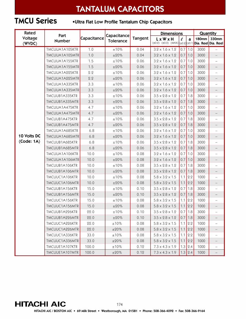
174
detaRegatloV)CDVW(
traPrebmuN
ecnaticapaCecnaticapaC
ecnareloTtnegnaT
RTK501A1AUUCMT 0.1 %01± 40.0 2.1x6.1x2.3 7.0 0.1 0003 –
RTM501A1AUUCMT 0.1 %02± 40.0 2.1x6.1x2.3 7.0 0.1 0003 –
RTK551A1AUUCMT 5.1 %01± 60.0 2.1x6.1x2.3 7.0 0.1 0003 –
RTM551A1AUUCMT 5.1 %02± 60.0 2.1x6.1x2.3 7.0 0.1 0003 –
RTK522A1AUUCMT 2.2 %01± 60.0 2.1x6.1x2.3 7.0 0.1 0003 –
RTM522A1AUUCMT 2.2 %02± 60.0 2.1x6.1x2.3 7.0 0.1 0003 –
RTK533A1AUUCMT 3.3 %01± 60.0 2.1x6.1x2.3 7.0 0.1 0003 –
RTM533A1AUUCMT 3.3 %02± 60.0 2.1x6.1x2.3 7.0 0.1 0003 –
RTK533A1BUUCMT 3.3 %01± 60.0 2.1x8.2x5.3 7.0 8.1 0003 –
RTM533A1BUUCMT 3.3 %02± 60.0 2.1x8.2x5.3 7.0 8.1 0003 –
RTK574A1AUUCMT 7.4 %01± 60.0 2.1x6.1x2.3 7.0 0.1 0003 –
RTM574A1AUUCMT 7.4 %02± 60.0 2.1x6.1x2.3 7.0 0.1 0003 –
RTK574A1BUUCMT 7.4 %01± 60.0 2.1x8.2x5.3 7.0 8.1 0003 –
RTM574A1BUUCMT 7.4 %02± 60.0 2.1x8.2x5.3 7.0 8.1 0003 –
RTK586A1AUUCMT 8.6 %01± 60.0 2.1x6.1x2.3 7.0 0.1 0003 –
RTM586A1AUUCMT 8.6 %02± 60.0 2.1x6.1x2.3 7.0 0.1 0003 –
RTK586A1BUUCMT 8.6 %01± 60.0 2.1x8.2x5.3 7.0 8.1 0003 –
RTM586A1BUUCMT 8.6 %02± 60.0 2.1x8.2x5.3 7.0 8.1 0003 –
RTK601A1AUUCMT 0.01 %01± 80.0 2.1x6.1x2.3 7.0 0.1 0003 –
RTM601A1AUUCMT 0.01 %02± 80.0 2.1x6.1x2.3 7.0 0.1 0003 –
RTK601A1BUUCMT 0.01 %01± 80.0 2.1x8.2x5.3 7.0 8.1 0003 –
RTM601A1BUUCMT 0.01 %02± 80.0 2.1x8.2x5.3 7.0 8.1 0003 –
RTK601A1CUUCMT 0.01 %01± 80.0 5.1x2.3x8.5 1.1 2.2 0001 –
RTM601A1CUUCMT 0.01 %02± 80.0 5.1x2.3x8.5 1.1 2.2 0001 –
RTK651A1BUUCMT 0.51 %01± 01.0 2.1x8.2x5.3 7.0 8.1 0003 –
RTM651A1BUUCMT 0.51 %02± 01.0 2.1x8.2x5.3 7.0 8.1 0003 –
RTK651A1CUUCMT 0.51 %01± 80.0 5.1x2.3x8.5 1.1 2.2 0001 –
RTM651A1CUUCMT 0.51 %02± 80.0 5.1x2.3x8.5 1.1 2.2 0001 –
RTK622A1BUUCMT 0.22 %01± 01.0 2.1x8.2x5.3 7.0 8.1 0003 –
RTM622A1BUUCMT 0.22 %02± 01.0 2.1x8.2x5.3 7.0 8.1 0003 –
RTK622A1CUUCMT 0.22 %01± 80.0 5.1x2.3x8.5 1.1 2.2 0001 –
RTM622A1CUUCMT 0.22 %02± 80.0 5.1x2.3x8.5 1.1 2.2 0001 –
RTK633A1CUUCMT 0.33 %01± 80.0 5.1x2.3x8.5 1.1 2.2 0001 –
RTM633A1CUUCMT 0.33 %02± 80.0 5.1x2.3x8.5 1.1 2.2 0001 –
RTK701A1EUUCMT 0.001 %01± 21.0 9.1x3.4x3.7 3.1 4.2 0001 –
RTM701A1EUUCMT 0.001 %02± 21.0 9.1x3.4x3.7 3.1 4.2 0001 –
TANTALUM CAPACITORS
AICHITACHI AIC / BOSTON AIC • 69 Milk Street • Westborough, MA 01581 • Phone: 508-366-4092 • Fax: 508-366-9164
TMCU Series •Ultra Flat Low Profile Tantalum Chip Capacitors
Dimensions L x W x H l a(±0.2) (±0.2) (MAX) (±0.2) (±0.1)
Quantity180mm
Dia. Reel330mm
Dia. Reel
10 Volts DC(Code: 1A)

175
detaRegatloV)CDVW(
traPrebmuN
ecnaticapaCecnaticapaC
ecnareloTtnegnaT
RTK486C1AUUCMT 86.0 %01± 40.0 2.1x6.1x2.3 7.0 0.1 0003 –
RTM486C1AUUCMT 86.0 %02± 40.0 2.1x6.1x2.3 7.0 0.1 0003 –
RTK501C1AUUCMT 0.1 %01± 40.0 2.1x6.1x2.3 7.0 0.1 0003 –
RTM501C1AUUCMT 0.1 %02± 40.0 2.1x6.1x2.3 7.0 0.1 0003 –
RTK551C1AUUCMT 5.1 %01± 60.0 2.1x6.1x2.3 7.0 0.1 0003 –
RTM551C1AUUCMT 5.1 %02± 60.0 2.1x6.1x2.3 7.0 0.1 0003 –
RTK522C1AUUCMT 2.2 %01± 60.0 2.1x6.1x2.3 7.0 0.1 0003 –
RTM522C1AUUCMT 2.2 %02± 60.0 2.1x6.1x2.3 7.0 0.1 0003 –
RTK522C1BUUCMT 2.2 %01± 60.0 2.1x8.2x5.3 7.0 8.1 0003 –
RTM522C1BUUCMT 2.2 %02± 60.0 2.1x8.2x5.3 7.0 8.1 0003 –
RTK533C1AUUCMT 3.3 %01± 60.0 2.1x6.1x2.3 7.0 0.1 0003 –
RTM533C1AUUCMT 3.3 %02± 60.0 2.1x6.1x2.3 7.0 0.1 0003 –
RTK533C1BUUCMT 3.3 %01± 60.0 2.1x8.2x5.3 7.0 8.1 0003 –
RTM533C1BUUCMT 3.3 %02± 60.0 2.1x8.2x5.3 7.0 8.1 0003 –
RTK574C1BUUCMT 7.4 %01± 60.0 2.1x8.2x5.3 7.0 8.1 0003 –
RTM574C1BUUCMT 7.4 %02± 60.0 2.1x8.2x5.3 7.0 8.1 0003 –
RTK586C1BUUCMT 8.6 %01± 60.0 2.1x8.2x5.3 7.0 8.1 0003 –
RTM586C1BUUCMT 8.6 %02± 60.0 2.1x8.2x5.3 7.0 8.1 0003 –
RTK586C1CUUCMT 8.6 %01± 60.0 5.1x2.3x8.5 1.1 2.2 0001 –
RTM586C1CUUCMT 8.6 %02± 60.0 5.1x2.3x8.5 1.1 2.2 0001 –
RTK601C1BUUCMT 0.01 %01± 80.0 2.1x8.2x5.3 7.0 8.1 0003 –
RTM601C1BUUCMT 0.01 %02± 80.0 2.1x8.2x5.3 7.0 8.1 0003 –
RTK601C1CUUCMT 0.01 %01± 80.0 5.1x2.3x8.5 1.1 2.2 0001 –
RTM601C1CUUCMT 0.01 %02± 80.0 5.1x2.3x8.5 1.1 2.2 0001 –
RTK651C1CUUCMT 0.51 %01± 80.0 5.1x2.3x8.5 1.1 2.2 0001 –
RTM651C1CUUCMT 0.51 %02± 80.0 5.1x2.3x8.5 1.1 2.2 0001 –
RTK674C1EUUCMT 0.74 %01± 80.0 9.1x3.4x3.7 3.1 4.2 0001 –
RTM674C1EUUCMT 0.74 %02± 80.0 9.1x3.4x3.7 3.1 4.2 0001 –
TANTALUM CAPACITORS
AICHITACHI AIC / BOSTON AIC • 69 Milk Street • Westborough, MA 01581 • Phone: 508-366-4092 • Fax: 508-366-9164
TMCU Series •Ultra Flat Low Profile Tantalum Chip Capacitors
Dimensions L x W x H l a(±0.2) (±0.2) (MAX) (±0.2) (±0.1)
Quantity180mm
Dia. Reel330mm
Dia. Reel
16 Volts DC(Code: 1C)
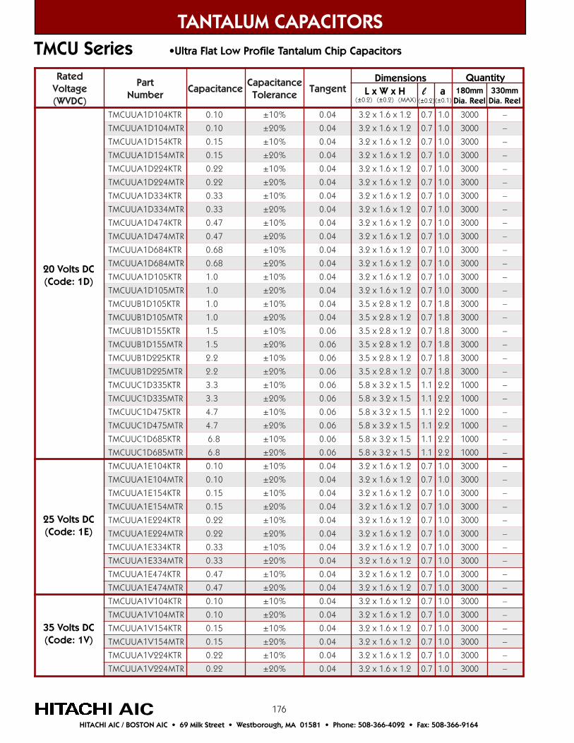
176
detaRegatloV)CDVW(
traPrebmuN
ecnaticapaCecnaticapaC
ecnareloTtnegnaT
RTK401D1AUUCMT 01.0 %01± 40.0 2.1x6.1x2.3 7.0 0.1 0003 –
RTM401D1AUUCMT 01.0 %02± 40.0 2.1x6.1x2.3 7.0 0.1 0003 –
RTK451D1AUUCMT 51.0 %01± 40.0 2.1x6.1x2.3 7.0 0.1 0003 –
RTM451D1AUUCMT 51.0 %02± 40.0 2.1x6.1x2.3 7.0 0.1 0003 –
RTK422D1AUUCMT 22.0 %01± 40.0 2.1x6.1x2.3 7.0 0.1 0003 –
RTM422D1AUUCMT 22.0 %02± 40.0 2.1x6.1x2.3 7.0 0.1 0003 –
RTK433D1AUUCMT 33.0 %01± 40.0 2.1x6.1x2.3 7.0 0.1 0003 –
RTM433D1AUUCMT 33.0 %02± 40.0 2.1x6.1x2.3 7.0 0.1 0003 –
RTK474D1AUUCMT 74.0 %01± 40.0 2.1x6.1x2.3 7.0 0.1 0003 –
RTM474D1AUUCMT 74.0 %02± 40.0 2.1x6.1x2.3 7.0 0.1 0003 –
RTK486D1AUUCMT 86.0 %01± 40.0 2.1x6.1x2.3 7.0 0.1 0003 –
RTM486D1AUUCMT 86.0 %02± 40.0 2.1x6.1x2.3 7.0 0.1 0003 –
RTK501D1AUUCMT 0.1 %01± 40.0 2.1x6.1x2.3 7.0 0.1 0003 –
RTM501D1AUUCMT 0.1 %02± 40.0 2.1x6.1x2.3 7.0 0.1 0003 –
RTK501D1BUUCMT 0.1 %01± 40.0 2.1x8.2x5.3 7.0 8.1 0003 –
RTM501D1BUUCMT 0.1 %02± 40.0 2.1x8.2x5.3 7.0 8.1 0003 –
RTK551D1BUUCMT 5.1 %01± 60.0 2.1x8.2x5.3 7.0 8.1 0003 –
RTM551D1BUUCMT 5.1 %02± 60.0 2.1x8.2x5.3 7.0 8.1 0003 –
RTK522D1BUUCMT 2.2 %01± 60.0 2.1x8.2x5.3 7.0 8.1 0003 –
RTM522D1BUUCMT 2.2 %02± 60.0 2.1x8.2x5.3 7.0 8.1 0003 –
RTK533D1CUUCMT 3.3 %01± 60.0 5.1x2.3x8.5 1.1 2.2 0001 –
RTM533D1CUUCMT 3.3 %02± 60.0 5.1x2.3x8.5 1.1 2.2 0001 –
RTK574D1CUUCMT 7.4 %01± 60.0 5.1x2.3x8.5 1.1 2.2 0001 –
RTM574D1CUUCMT 7.4 %02± 60.0 5.1x2.3x8.5 1.1 2.2 0001 –
RTK586D1CUUCMT 8.6 %01± 60.0 5.1x2.3x8.5 1.1 2.2 0001 –
RTM586D1CUUCMT 8.6 %02± 60.0 5.1x2.3x8.5 1.1 2.2 0001 –
RTK401E1AUUCMT 01.0 %01± 40.0 2.1x6.1x2.3 7.0 0.1 0003 –
RTM401E1AUUCMT 01.0 %02± 40.0 2.1x6.1x2.3 7.0 0.1 0003 –
RTK451E1AUUCMT 51.0 %01± 40.0 2.1x6.1x2.3 7.0 0.1 0003 –
RTM451E1AUUCMT 51.0 %02± 40.0 2.1x6.1x2.3 7.0 0.1 0003 –
RTK422E1AUUCMT 22.0 %01± 40.0 2.1x6.1x2.3 7.0 0.1 0003 –
RTM422E1AUUCMT 22.0 %02± 40.0 2.1x6.1x2.3 7.0 0.1 0003 –
RTK433E1AUUCMT 33.0 %01± 40.0 2.1x6.1x2.3 7.0 0.1 0003 –
RTM433E1AUUCMT 33.0 %02± 40.0 2.1x6.1x2.3 7.0 0.1 0003 –
RTK474E1AUUCMT 74.0 %01± 40.0 2.1x6.1x2.3 7.0 0.1 0003 –
RTM474E1AUUCMT 74.0 %02± 40.0 2.1x6.1x2.3 7.0 0.1 0003 –
RTK401V1AUUCMT 01.0 %01± 40.0 2.1x6.1x2.3 7.0 0.1 0003 –
RTM401V1AUUCMT 01.0 %02± 40.0 2.1x6.1x2.3 7.0 0.1 0003 –
RTK451V1AUUCMT 51.0 %01± 40.0 2.1x6.1x2.3 7.0 0.1 0003 –
RTM451V1AUUCMT 51.0 %02± 40.0 2.1x6.1x2.3 7.0 0.1 0003 –
RTK422V1AUUCMT 22.0 %01± 40.0 2.1x6.1x2.3 7.0 0.1 0003 –
RTM422V1AUUCMT 22.0 %02± 40.0 2.1x6.1x2.3 7.0 0.1 0003 –
TANTALUM CAPACITORS
AICHITACHI AIC / BOSTON AIC • 69 Milk Street • Westborough, MA 01581 • Phone: 508-366-4092 • Fax: 508-366-9164
TMCU Series •Ultra Flat Low Profile Tantalum Chip Capacitors
Dimensions L x W x H l a(±0.2) (±0.2) (MAX) (±0.2) (±0.1)
Quantity180mm
Dia. Reel330mm
Dia. Reel
20 Volts DC(Code: 1D)
25 Volts DC(Code: 1E)
35 Volts DC(Code: 1V)
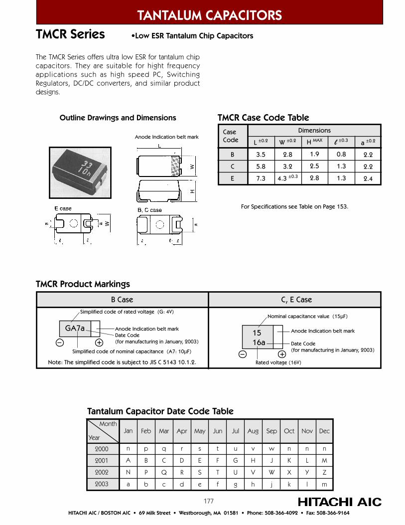
177
TANTALUM CAPACITORS
AICHITACHI AIC / BOSTON AIC • 69 Milk Street • Westborough, MA 01581 • Phone: 508-366-4092 • Fax: 508-366-9164
TMCR Series •Low ESR Tantalum Chip Capacitors
The TMCR Series offers ultra low ESR for tantalum chipcapacitors. They are suitable for hight frequencyapplications such as high speed PC, SwitchingRegulators, DC/DC converters, and similar productdesigns.
Jan
n
A
N
a
Feb
p
B
P
b
Mar
q
C
Q
c
Sep
w
J
W
j
Aug
v
H
V
h
Jul
u
G
U
g
Jun
t
F
T
f
May
s
E
S
e
Apr
r
D
R
d
Dec
n
M
Z
m
Nov
n
L
Y
l
Oct
n
K
X
k
Month
Year
2000
2001
2002
2003
Tantalum Capacitor Date Code Table
B Case C, E CaseSimplified code of rated voltage (G: 4V)
+–
Note: The simplified code is subject to JIS C 5143 10.1.2.
GA7a Anode Indication belt markDate Code(for manufacturing in January, 2003)
1516a
Nominal capacitance value (15µF)
Anode Indication belt mark
Date Code(for manufacturing in January, 2003)
+–Rated voltage (16V)
TMCR Product Markings
Outline Drawings and Dimensions
Anode Indication belt mark
For Specifications see Table on Page 153.
TMCR Case Code Table
CaseCode
B
C
E
L ±0.2
3.5
5.8
7.3
Dimensions
W ±0.2
2.8
3.2
4.3 ±0.3
H MAX
1.9
2.5
2.8
l ±0.3
0.8
1.3
1.3
a ±0.2
2.2
2.2
2.4
Simplified code of nominal capacitance (A7: 10µF)

178
detaRegatloV)CDVW(
traPrebmuN
ecnaticapaCecnaticapaC
ecnareloTtnegnaT
RSEC°02@
RTK601J0BRCMT 01 %01± 60.0 7.0 9.1x8.2x5.3 8.0 2.2 0002 0008
RTM601J0BRCMT 01 %02± 60.0 7.0 9.1x8.2x5.3 8.0 2.2 0002 0008
RTK651J0BRCMT 51 %01± 60.0 6.0 9.1x8.2x5.3 8.0 2.2 0003 0008
RTM651J0BRCMT 51 %02± 60.0 6.0 9.1x8.2x5.3 8.0 2.2 0003 0008
RTK622J0BRCMT 22 %01± 60.0 5.0 9.1x8.2x5.3 8.0 2.2 0003 0008
RTM622J0BRCMT 22 %02± 60.0 5.0 9.1x8.2x5.3 8.0 2.2 0003 0008
RTK633J0CRCMT 33 %01± 60.0 53.0 5.2x2.3x8.5 3.1 2.2 005 0052
RTM633J0CRCMT 33 %02± 60.0 53.0 5.2x2.3x8.5 3.1 2.2 005 0052
RTK674J0CRCMT 74 %01± 60.0 53.0 5.2x2.3x8.5 3.1 2.2 005 0052
RTM674J0CRCMT 74 %02± 60.0 53.0 5.2x2.3x8.5 3.1 2.2 005 0052
RTK686J0ERCMT 86 %01± 60.0 2.0 8.2x*3.4x3.7 3.1 4.2 005 0052
RTM686J0ERCMT 86 %02± 60.0 2.0 8.2x*3.4x3.7 3.1 4.2 005 0052
RTK701J0ERCMT 001 %01± 80.0 1.0 8.2x*3.4x3.7 3.1 4.2 005 0052
RTM701J0ERCMT 001 %02± 80.0 1.0 8.2x*3.4x3.7 3.1 4.2 005 0052
RTK751J0EPCMT 051 %01± 80.0 1.0 8.2x*3.4x3.7 3.1 4.2 005 0052
RTM751J0EPCMT 051 %02± 80.0 1.0 8.2x*3.4x3.7 3.1 4.2 005 0052
RTK722J0EPCMT 022 %01± 01.0 1.0 8.2x*3.4x3.7 3.1 4.2 005 0052
RTM722J0EPCMT 022 %02± 01.0 1.0 8.2x*3.4x3.7 3.1 4.2 005 0052
RTK733J0EPCMT 033 %01± 51.0 1.0 8.2x*3.4x3.7 3.1 4.2 005 0052
RTM733J0EPCMT 033 %02± 51.0 1.0 8.2x*3.4x3.7 3.1 4.2 005 0052
RTK601A1BRCMT 01 %01± 60.0 7.0 9.1x8.2x5.3 8.0 2.2 0002 0008
RTM601A1BRCMT 01 %02± 60.0 7.0 9.1x8.2x5.3 8.0 2.2 0002 0008
RTK651A1BRCMT 51 %01± 60.0 6.0 9.1x8.2x5.3 8.0 2.2 0003 0008
RTM651A1BRCMT 51 %02± 60.0 6.0 9.1x8.2x5.3 8.0 2.2 0003 0008
RTK622A1BRCMT 22 %01± 60.0 5.0 9.1x8.2x5.3 8.0 2.2 0003 0008
RTM622A1BRCMT 22 %02± 60.0 5.0 9.1x8.2x5.3 8.0 2.2 0003 0008
RTK633A1CRCMT 33 %01± 60.0 53.0 5.2x2.3x8.5 3.1 2.2 005 0052
RTM633A1CRCMT 33 %02± 60.0 53.0 5.2x2.3x8.5 3.1 2.2 005 0052
RTK674A1CRCMT 74 %01± 60.0 52.0 5.2x2.3x8.5 3.1 2.2 005 0052
RTM674A1CRCMT 74 %02± 60.0 52.0 5.2x2.3x8.5 3.1 2.2 005 0052
RTK686A1ERCMT 86 %01± 60.0 2.0 8.2x*3.4x3.7 3.1 4.2 005 0052
RTM686A1ERCMT 86 %02± 60.0 2.0 8.2x*3.4x3.7 3.1 4.2 005 0052
RTK701A1ERCMT 001 %01± 80.0 1.0 8.2x*3.4x3.7 3.1 4.2 005 0052
RTM701A1ERCMT 001 %02± 80.0 1.0 8.2x*3.4x3.7 3.1 4.2 005 0052
RTK751A1EPCMT 051 %01± 80.0 1.0 8.2x*3.4x3.7 3.1 4.2 005 0052
RTM751A1EPCMT 051 %02± 80.0 1.0 8.2x*3.4x3.7 3.1 4.2 005 0052
RTK722A1EPCMT 022 %01± 01.0 1.0 8.2x*3.4x3.7 3.1 4.2 005 0052
RTM722A1EPCMT 022 %02± 01.0 1.0 8.2x*3.4x3.7 3.1 4.2 005 0052
TANTALUM CAPACITORS
AICHITACHI AIC / BOSTON AIC • 69 Milk Street • Westborough, MA 01581 • Phone: 508-366-4092 • Fax: 508-366-9164
TMCR Series •Low ESR Tantalum Chip Capacitors
6.3 Volts DC(Code: 0J)
10 Volts DC(Code: 1A)
DimensionsL x W* x H l a
(±0.2) (±0.2) (MAX) (±0.3) (±0.2)
Quantity180mm
Dia. Reel330mm
Dia. Reel
*Case Code E: Width (W) = ±0.3

179
detaRegatloV)CDVW(
traPrebmuN
ecnaticapaCecnaticapaC
ecnareloTtnegnaT
RSEC°02@
RTK601C1BRCMT 01 %01± 60.0 6.0 9.1x8.2x5.3 8.0 2.2 0002 0008
RTM601C1BRCMT 01 %02± 60.0 6.0 9.1x8.2x5.3 8.0 2.2 0002 0008
RTK651C1CRCMT 51 %01± 60.0 5.0 5.2x2.3x8.5 3.1 2.2 005 0052
RTM651C1CRCMT 51 %02± 60.0 5.0 5.2x2.3x8.5 3.1 2.2 005 0052
RTK622C1CRCMT 22 %01± 60.0 4.0 5.2x2.3x8.5 3.1 2.2 005 0052
RTM622C1CRCMT 22 %02± 60.0 4.0 5.2x2.3x8.5 3.1 2.2 005 0052
RTK633C1ERCMT 33 %01± 60.0 52.0 8.2x*3.4x3.7 3.1 4.2 005 0052
RTM633C1ERCMT 33 %02± 60.0 52.0 8.2x*3.4x3.7 3.1 4.2 005 0052
RTK674C1ERCMT 74 %01± 60.0 2.0 8.2x*3.4x3.7 3.1 4.2 005 0052
RTM674C1ERCMT 74 %02± 60.0 2.0 8.2x*3.4x3.7 3.1 4.2 005 0052
RTK686C1ERCMT 86 %01± 60.0 51.0 8.2x*3.4x3.7 3.1 4.2 005 0052
RTM686C1ERCMT 86 %02± 60.0 51.0 8.2x*3.4x3.7 3.1 4.2 005 0052
RTK701C1ERCMT 001 %01± 80.0 1.0 8.2x*3.4x3.7 3.1 4.2 005 0052
RTM701C1ERCMT 001 %02± 80.0 1.0 8.2x*3.4x3.7 3.1 4.2 005 0052
RTK601D1CRCMT 01 %01± 60.0 6.0 5.2x2.3x8.5 3.1 2.2 005 0052
RTM601D1CRCMT 01 %02± 60.0 6.0 5.2x2.3x8.5 3.1 2.2 005 0052
RTK651D1CRCMT 51 %01± 60.0 5.0 5.2x2.3x8.5 3.1 2.2 005 0052
RTM651D1CRCMT 51 %02± 60.0 5.0 5.2x2.3x8.5 3.1 2.2 005 0052
RTK622D1ERCMT 22 %01± 60.0 53.0 8.2x*3.4x3.7 3.1 4.2 005 0052
RTM622D1ERCMT 22 %02± 60.0 53.0 8.2x*3.4x3.7 3.1 4.2 005 0052
RTK633D1ERCMT 33 %01± 60.0 3.0 8.2x*3.4x3.7 3.1 4.2 005 0052
RTM633D1ERCMT 33 %02± 60.0 3.0 8.2x*3.4x3.7 3.1 4.2 005 0052
RTK674D1ERCMT 74 %01± 60.0 2.0 8.2x*3.4x3.7 3.1 4.2 005 0052
RTM674D1ERCMT 74 %02± 60.0 2.0 8.2x*3.4x3.7 3.1 4.2 005 0052
RTK601E1ERCMT 01 %01± 60.0 3.0 8.2x*3.4x3.7 3.1 4.2 005 0052
RTM601E1ERCMT 01 %02± 60.0 3.0 8.2x*3.4x3.7 3.1 4.2 005 0052
RTK651E1ERCMT 51 %01± 60.0 3.0 8.2x*3.4x3.7 3.1 4.2 005 0052
RTM651E1ERCMT 51 %02± 60.0 3.0 8.2x*3.4x3.7 3.1 4.2 005 0052
RTK622E1ERCMT 22 %01± 60.0 3.0 8.2x*3.4x3.7 3.1 4.2 005 0052
RTM622E1ERCMT 22 %02± 60.0 3.0 8.2x*3.4x3.7 3.1 4.2 005 0052
RTK633E1ERCMT 33 %01± 60.0 3.0 8.2x*3.4x3.7 3.1 4.2 005 0052
RTM633E1ERCMT 33 %02± 60.0 3.0 8.2x*3.4x3.7 3.1 4.2 005 0052
RTK601V1ERCMT 01 %01± 60.0 3.0 8.2x*3.4x3.7 3.1 4.2 005 0052
RTM601V1ERCMT 01 %02± 60.0 3.0 8.2x*3.4x3.7 3.1 4.2 005 0052
RTK651V1ERCMT 51 %01± 60.0 3.0 8.2x*3.4x3.7 3.1 4.2 005 0052
RTM651V1ERCMT 51 %02± 60.0 3.0 8.2x*3.4x3.7 3.1 4.2 005 0052
RTK622V1ERCMT 22 %01± 60.0 5.0 8.2x*3.4x3.7 3.1 4.2 005 0052
RTM622V1ERCMT 22 %02± 60.0 5.0 8.2x*3.4x3.7 3.1 4.2 005 0052
TANTALUM CAPACITORS
AICHITACHI AIC / BOSTON AIC • 69 Milk Street • Westborough, MA 01581 • Phone: 508-366-4092 • Fax: 508-366-9164
TMCR Series •Low ESR Tantalum Chip Capacitors
16 Volts DC(Code: 1C)
20 Volts DC(Code: 1D)
DimensionsL x W* x H l a
(±0.2) (±0.2) (MAX) (±0.3) (±0.2)
Quantity180mm
Dia. Reel330mm
Dia. Reel
25 Volts DC(Code: 1E)
35 Volts DC(Code: 1V)
*Case Code E: Width (W) = ±0.3
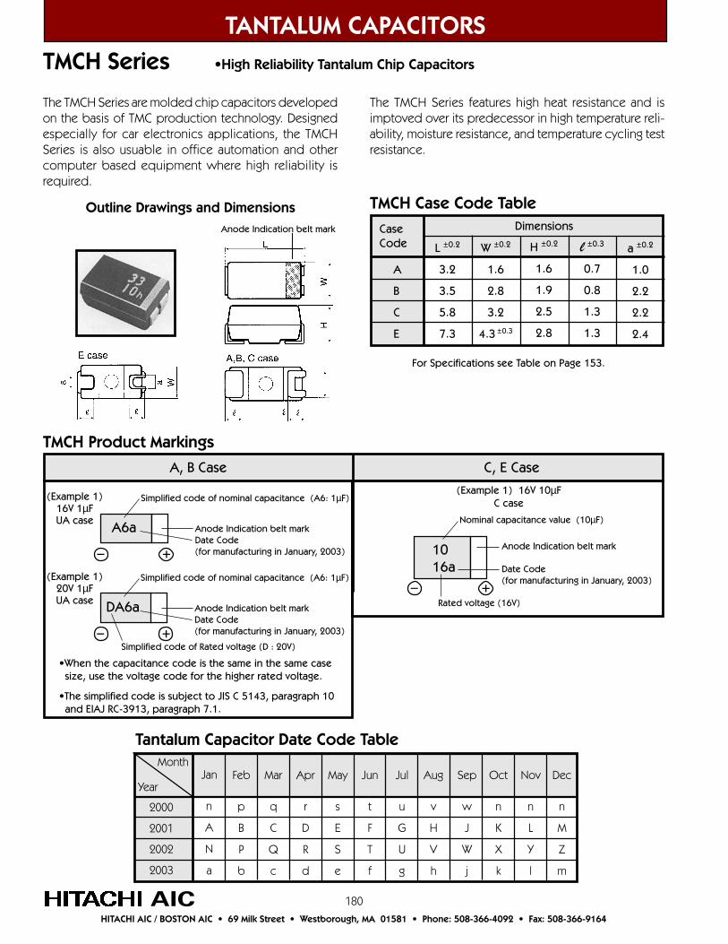
180
TANTALUM CAPACITORS
AICHITACHI AIC / BOSTON AIC • 69 Milk Street • Westborough, MA 01581 • Phone: 508-366-4092 • Fax: 508-366-9164
TMCH Series •High Reliability Tantalum Chip Capacitors
The TMCH Series are molded chip capacitors developedon the basis of TMC production technology. Designedespecially for car electronics applications, the TMCHSeries is also usuable in office automation and othercomputer based equipment where high reliability isrequired.
The TMCH Series features high heat resistance and isimptoved over its predecessor in high temperature reli-ability, moisture resistance, and temperature cycling testresistance.
Jan
n
A
N
a
Feb
p
B
P
b
Mar
q
C
Q
c
Sep
w
J
W
j
Aug
v
H
V
h
Jul
u
G
U
g
Jun
t
F
T
f
May
s
E
S
e
Apr
r
D
R
d
Dec
n
M
Z
m
Nov
n
L
Y
l
Oct
n
K
X
k
Month
Year
2000
2001
2002
2003
Tantalum Capacitor Date Code Table
A, B Case C, E Case
Simplified code of nominal capacitance (A6: 1µF)
+–
•When the capacitance code is the same in the same case size, use the voltage code for the higher rated voltage.
•The simplified code is subject to JIS C 5143, paragraph 10 and EIAJ RC-3913, paragraph 7.1.
A6a Anode Indication belt markDate Code(for manufacturing in January, 2003) 10
16a
Nominal capacitance value (10µF)
Anode Indication belt mark
Date Code(for manufacturing in January, 2003)
+–Rated voltage (16V)
TMCH Product Markings
Outline Drawings and DimensionsAnode Indication belt mark
For Specifications see Table on Page 153.
TMCH Case Code Table
CaseCode
A
B
C
E
L ±0.2
3.2
3.5
5.8
7.3
Dimensions
W ±0.2
1.6
2.8
3.2
4.3 ±0.3
H ±0.2
1.6
1.9
2.5
2.8
l ±0.3
0.7
0.8
1.3
1.3
a ±0.2
1.0
2.2
2.2
2.4
(Example 1) 16V 10µFC case
Simplified code of nominal capacitance (A6: 1µF)
+–
DA6a Anode Indication belt markDate Code(for manufacturing in January, 2003)
(Example 1)16V 1µFUA case
(Example 1)20V 1µFUA case
Simplified code of Rated voltage (D : 20V)

181
TANTALUM CAPACITORS
AICHITACHI AIC / BOSTON AIC • 69 Milk Street • Westborough, MA 01581 • Phone: 508-366-4092 • Fax: 508-366-9164
TMCH Series •High Reliavility Tantalum Chip Capacitors
detaRegatloV)CDVW(
traPrebmuN
ecnaticapaCecnaticapaC
ecnareloTtnegnaT
RTK533G0AHCMT 3.3 %01± 60.0 6.1x6.1x2.3 7.0 2.1 0002 0008RTM533G0AHCMT 3.3 %02± 60.0 6.1x6.1x2.3 7.0 2.1 0002 0008
RTK574G0AHCMT 7.4 %01± 60.0 6.1x6.1x2.3 7.0 2.1 0002 0008RTM574G0AHCMT 7.4 %02± 60.0 6.1x6.1x2.3 7.0 2.1 0002 0008
RTK601G0BHCMT 0.01 %01± 60.0 9.1x8.2x5.3 8.0 2.2 0002 0008RTM601G0BHCMT 0.01 %02± 60.0 9.1x8.2x5.3 8.0 2.2 0002 0008
RTK651G0BHCMT 0.51 %01± 60.0 9.1x8.2x5.3 8.0 2.2 0002 0008RTM651G0BHCMT 0.51 %02± 60.0 9.1x8.2x5.3 8.0 2.2 0002 0008RTK633G0CHCMT 0.33 %01± 60.0 5.2x2.3x8.5 3.1 2.2 005 0052RTM633G0CHCMT 0.33 %02± 60.0 5.2x2.3x8.5 3.1 2.2 005 0052
RTK674G0CHCMT 0.74 %01± 60.0 5.2x2.3x8.5 3.1 2.2 005 0052RTM674G0CHCMT 0.74 %02± 60.0 5.2x2.3x8.5 3.1 2.2 005 0052
RTK686G0EHCMT 0.86 %01± 60.0 8.2x*3.4x3.7 3.1 4.2 005 0052RTM686G0EHCMT 0.86 %02± 60.0 8.2x*3.4x3.7 3.1 4.2 005 0052
RTK701G0EHCMT 0.001 %01± 60.0 8.2x*3.4x3.7 3.1 4.2 005 0052RTM701G0EHCMT 0.001 %02± 60.0 8.2x*3.4x3.7 3.1 4.2 005 0052
RTK522J0AHCMT 2.2 %01± 60.0 6.1x6.1x2.3 7.0 2.1 0002 0008RTM522J0AHCMT 2.2 %02± 60.0 6.1x6.1x2.3 7.0 2.1 0002 0008
RTK533J0AHCMT 3.3 %01± 60.0 6.1x6.1x2.3 7.0 2.1 0002 0008RTM533J0AHCMT 3.3 %02± 60.0 6.1x6.1x2.3 7.0 2.1 0002 0008
RTK586J0BHCMT 8.6 %01± 60.0 9.1x8.2x5.3 8.0 2.2 0002 0008RTM586J0BHCMT 8.6 %02± 60.0 9.1x8.2x5.3 8.0 2.2 0002 0008
RTK601J0BHCMT 0.01 %01± 60.0 9.1x8.2x5.3 8.0 2.2 0002 0008RTM601J0BHCMT 0.01 %02± 60.0 9.1x8.2x5.3 8.0 2.2 0002 0008RTK622J0CHCMT 0.22 %01± 60.0 5.2x2.3x8.5 3.1 2.2 005 0052RTM622J0CHCMT 0.22 %02± 60.0 5.2x2.3x8.5 3.1 2.2 005 0052
RTK633J0CHCMT 0.33 %01± 60.0 5.2x2.3x8.5 3.1 2.2 005 0052RTM633J0CHCMT 0.33 %02± 60.0 5.2x2.3x8.5 3.1 2.2 005 0052
RTK674J0EHCMT 0.74 %01± 60.0 8.2x*3.4x3.7 3.1 4.2 005 0052RTM674J0EHCMT 0.74 %02± 60.0 8.2x*3.4x3.7 3.1 4.2 005 0052
RTK686J0EHCMT 0.86 %01± 60.0 8.2x*3.4x3.7 3.1 4.2 005 0052RTM686J0EHCMT 0.86 %02± 60.0 8.2x*3.4x3.7 3.1 4.2 005 0052RTK551A1AHCMT 5.1 %01± 60.0 6.1x6.1x2.3 7.0 2.1 0002 0008RTM551A1AHCMT 5.1 %02± 60.0 6.1x6.1x2.3 7.0 2.1 0002 0008
RTK522A1AHCMT 2.2 %01± 60.0 6.1x6.1x2.3 7.0 2.1 0002 0008RTM522A1AHCMT 2.2 %02± 60.0 6.1x6.1x2.3 7.0 2.1 0002 0008
RTK533A1BHCMT 3.3 %01± 60.0 9.1x8.2x5.3 8.0 2.2 0002 0008RTM533A1BHCMT 3.3 %02± 60.0 9.1x8.2x5.3 8.0 2.2 0002 0008
RTK586A1BHCMT 8.6 %01± 60.0 9.1x8.2x5.3 8.0 2.2 0002 0008RTM586A1BHCMT 8.6 %02± 60.0 9.1x8.2x5.3 8.0 2.2 0002 0008RTK651A1CHCMT 0.51 %01± 60.0 5.2x2.3x8.5 3.1 2.2 005 0052RTM651A1CHCMT 0.51 %02± 60.0 5.2x2.3x8.5 3.1 2.2 005 0052
RTK622A1CHCMT 0.22 %01± 60.0 5.2x2.3x8.5 3.1 2.2 005 0052RTM622A1CHCMT 0.22 %02± 60.0 5.2x2.3x8.5 3.1 2.2 005 0052
RTK633A1EHCMT 0.33 %01± 60.0 8.2x*3.4x3.7 3.1 4.2 005 0052RTM633A1EHCMT 0.33 %02± 60.0 8.2x*3.4x3.7 3.1 4.2 005 0052
RTK674A1EHCMT 0.74 %01± 60.0 8.2x*3.4x3.7 3.1 4.2 005 0052RTM674A1EHCMT 0.74 %02± 60.0 8.2x*3.4x3.7 3.1 4.2 005 0052
*Case Code E: Width (W) = ±0.3
Dimensions L x W* x H l a(±0.2) (±0.2) (±0.2) (±0.3) (±0.2)
Quantity180mm
Dia. Reel330mm
Dia. Reel
4 Volts DC(Code: 0G)
7 Volts DC(Code: 0J)
10 Volts DC(Code: 1A)

182
detaRegatloV)CDVW(
traPrebmuN
ecnaticapaCecnaticapaC
ecnareloTtnegnaT
RTK501C1AHCMT 0.1 %01± 40.0 6.1x6.1x2.3 7.0 2.1 0002 0008RTM501C1AHCMT 0.1 %02± 40.0 6.1x6.1x2.3 7.0 2.1 0002 0008
RTK551C1AHCMT 5.1 %01± 60.0 6.1x6.1x2.3 7.0 2.1 0002 0008RTM551C1AHCMT 5.1 %02± 60.0 6.1x6.1x2.3 7.0 2.1 0002 0008
RTK533C1BHCMT 3.3 %01± 60.0 9.1x8.2x5.3 8.0 2.2 0002 0008RTM533C1BHCMT 3.3 %02± 60.0 9.1x8.2x5.3 8.0 2.2 0002 0008
RTK574C1BHCMT 7.4 %01± 60.0 9.1x8.2x5.3 8.0 2.2 0002 0008RTM574C1BHCMT 7.4 %02± 60.0 9.1x8.2x5.3 8.0 2.2 0002 0008RTK601C1CHCMT 0.01 %01± 60.0 5.2x2.3x8.5 3.1 2.2 005 0052RTM601C1CHCMT 0.01 %02± 60.0 5.2x2.3x8.5 3.1 2.2 005 0052
RTK651C1CHCMT 0.51 %01± 60.0 5.2x2.3x8.5 3.1 2.2 005 0052RTM651C1CHCMT 0.51 %02± 60.0 5.2x2.3x8.5 3.1 2.2 005 0052
RTK622C1EHCMT 0.22 %01± 60.0 8.2x*3.4x3.7 3.1 4.2 005 0052RTM622C1EHCMT 0.22 %02± 60.0 8.2x*3.4x3.7 3.1 4.2 005 0052
RTK633C1EHCMT 0.33 %01± 60.0 8.2x*3.4x3.7 3.1 4.2 005 0052RTM633C1EHCMT 0.33 %02± 60.0 8.2x*3.4x3.7 3.1 4.2 005 0052RTK486D1AHCMT 86.0 %01± 40.0 6.1x6.1x2.3 7.0 2.1 0002 0008RTM486D1AHCMT 86.0 %02± 40.0 6.1x6.1x2.3 7.0 2.1 0002 0008
RTK501D1AHCMT 0.1 %01± 40.0 6.1x6.1x2.3 7.0 2.1 0002 0008RTM501D1AHCMT 0.1 %02± 40.0 6.1x6.1x2.3 7.0 2.1 0002 0008
RTK522D1BHCMT 2.2 %01± 60.0 9.1x8.2x5.3 8.0 2.2 0002 0008RTM522D1BHCMT 2.2 %02± 60.0 9.1x8.2x5.3 8.0 2.2 0002 0008
RTK533D1BHCMT 3.3 %01± 60.0 9.1x8.2x5.3 8.0 2.2 0002 0008RTM533D1BHCMT 3.3 %02± 60.0 9.1x8.2x5.3 8.0 2.2 0002 0008RTK586D1CHCMT 8.6 %01± 60.0 5.2x2.3x8.5 3.1 2.2 005 0052RTM586D1CHCMT 8.6 %02± 60.0 5.2x2.3x8.5 3.1 2.2 005 0052
RTK601D1CHCMT 0.01 %01± 60.0 5.2x2.3x8.5 3.1 2.2 005 0052RTM601D1CHCMT 0.01 %02± 60.0 5.2x2.3x8.5 3.1 2.2 005 0052
RTK651D1EHCMT 0.51 %01± 60.0 8.2x*3.4x3.7 3.1 4.2 005 0052RTM651D1EHCMT 0.51 %02± 60.0 8.2x*3.4x3.7 3.1 4.2 005 0052
RTK622D1EHCMT 0.22 %01± 60.0 8.2x*3.4x3.7 3.1 4.2 005 0052RTM622D1EHCMT 0.22 %02± 60.0 8.2x*3.4x3.7 3.1 4.2 005 0052RTK474E1AHCMT 74.0 %01± 40.0 6.1x6.1x2.3 7.0 2.1 0002 0008RTM474E1AHCMT 74.0 %02± 40.0 6.1x6.1x2.3 7.0 2.1 0002 0008
RTK486E1AHCMT 86.0 %01± 40.0 6.1x6.1x2.3 7.0 2.1 0002 0008RTM486E1AHCMT 86.0 %02± 40.0 6.1x6.1x2.3 7.0 2.1 0002 0008
RTK551E1BHCMT 5.1 %01± 60.0 9.1x8.2x5.3 8.0 2.2 0002 0008RTM551E1BHCMT 5.1 %02± 60.0 9.1x8.2x5.3 8.0 2.2 0002 0008
RTK522E1BHCMT 2.2 %01± 60.0 9.1x8.2x5.3 8.0 2.2 0002 0008RTM522E1BHCMT 2.2 %02± 60.0 9.1x8.2x5.3 8.0 2.2 0002 0008RTK574E1CHCMT 7.4 %01± 60.0 5.2x2.3x8.5 3.1 2.2 005 0052RTM574E1CHCMT 7.4 %02± 60.0 5.2x2.3x8.5 3.1 2.2 005 0052
RTK586E1CHCMT 8.6 %01± 60.0 5.2x2.3x8.5 3.1 2.2 005 0052RTM586E1CHCMT 8.6 %02± 60.0 5.2x2.3x8.5 3.1 2.2 005 0052
RTK601E1EHCMT 0.01 %01± 60.0 8.2x*3.4x3.7 3.1 4.2 005 0052RTM601E1EHCMT 0.01 %02± 60.0 8.2x*3.4x3.7 3.1 4.2 005 0052
RTK651E1EHCMT 0.51 %01± 60.0 8.2x*3.4x3.7 3.1 4.2 005 0052RTM651E1EHCMT 0.51 %02± 60.0 8.2x*3.4x3.7 3.1 4.2 005 0052
TANTALUM CAPACITORS
AICHITACHI AIC / BOSTON AIC • 69 Milk Street • Westborough, MA 01581 • Phone: 508-366-4092 • Fax: 508-366-9164
TMCH Series •High Reliability Tantalum Chip Capacitors
16 Volts DC(Code: 1C)
20 Volts DC(Code: 1D)
25 Volts DC(Code: 1E)
Dimensions L x W* x H l a(±0.2) (±0.2) (±0.2) (±0.3) (±0.2)
Quantity180mm
Dia. Reel330mm
Dia. Reel
*Case Code E: Width (W) = ±0.3

183
detaRegatloV)CDVW(
traPrebmuN
ecnaticapaCecnaticapaC
ecnareloTtnegnaT
RTK401V1AHCMT 01.0 %01± 40.0 6.1x6.1x2.3 7.0 2.1 0002 0008RTM401V1AHCMT 01.0 %02± 40.0 6.1x6.1x2.3 7.0 2.1 0002 0008
RTK451V1AHCMT 51.0 %01± 40.0 6.1x6.1x2.3 7.0 2.1 0002 0008RTM451V1AHCMT 51.0 %02± 40.0 6.1x6.1x2.3 7.0 2.1 0002 0008
RTK422V1AHCMT 22.0 %01± 40.0 6.1x6.1x2.3 7.0 2.1 0002 0008RTM422V1AHCMT 22.0 %02± 40.0 6.1x6.1x2.3 7.0 2.1 0002 0008
RTK433V1AHCMT 33.0 %01± 40.0 6.1x6.1x2.3 7.0 2.1 0002 0008RTM433V1AHCMT 33.0 %02± 40.0 6.1x6.1x2.3 7.0 2.1 0002 0008
RTK474V1AHCMT 74.0 %01± 40.0 6.1x6.1x2.3 7.0 2.1 0002 0008RTM474V1AHCMT 74.0 %02± 40.0 6.1x6.1x2.3 7.0 2.1 0002 0008
RTK474V1BHCMT 74.0 %01± 40.0 9.1x8.2x5.3 8.0 2.2 0002 0008RTM474V1BHCMT 74.0 %02± 40.0 9.1x8.2x5.3 8.0 2.2 0002 0008
RTK486V1BHCMT 86.0 %01± 40.0 9.1x8.2x5.3 8.0 2.2 0002 0008RTM486V1BHCMT 86.0 %02± 40.0 9.1x8.2x5.3 8.0 2.2 0002 0008
RTK501V1BHCMT 0.1 %01± 40.0 9.1x8.2x5.3 8.0 2.2 0002 0008RTM501V1BHCMT 0.1 %02± 40.0 9.1x8.2x5.3 8.0 2.2 0002 0008
RTK551V1BHCMT 5.1 %01± 60.0 9.1x8.2x5.3 8.0 2.2 0002 0008RTM551V1BHCMT 5.1 %02± 60.0 9.1x8.2x5.3 8.0 2.2 0002 0008RTK551V1CHCMT 5.1 %01± 60.0 5.2x2.3x8.5 3.1 2.2 005 0052RTM551V1CHCMT 5.1 %02± 60.0 5.2x2.3x8.5 3.1 2.2 005 0052
RTK522V1CHCMT 2.2 %01± 60.0 5.2x2.3x8.5 3.1 2.2 005 0052RTM522V1CHCMT 2.2 %02± 60.0 5.2x2.3x8.5 3.1 2.2 005 0052
RTK533V1CHCMT 3.3 %01± 60.0 5.2x2.3x8.5 3.1 2.2 005 0052RTM533V1CHCMT 3.3 %02± 60.0 5.2x2.3x8.5 3.1 2.2 005 0052
RTK574V1CHCMT 7.4 %01± 60.0 5.2x2.3x8.5 3.1 2.2 005 0052RTM574V1CHCMT 7.4 %02± 60.0 5.2x2.3x8.5 3.1 2.2 005 0052
RTK574V1EHCMT 7.4 %01± 60.0 8.2x*3.4x3.7 3.1 4.2 005 0052RTM574V1EHCMT 7.4 %02± 60.0 8.2x*3.4x3.7 3.1 4.2 005 0052
RTK586V1EHCMT 8.6 %01± 60.0 8.2x*3.4x3.7 3.1 4.2 005 0052RTM586V1EHCMT 8.6 %02± 60.0 8.2x*3.4x3.7 3.1 4.2 005 0052
RTK601V1EHCMT 0.01 %01± 60.0 8.2x*3.4x3.7 3.1 4.2 005 0052RTM601V1EHCMT 0.01 %02± 60.0 8.2x*3.4x3.7 3.1 4.2 005 0052RTK401H1AHCMT 01.0 %01± 40.0 6.1x6.1x2.3 7.0 2.1 0002 0008RTM401H1AHCMT 01.0 %02± 40.0 6.1x6.1x2.3 7.0 2.1 0002 0008
RTK451H1BHCMT 51.0 %01± 40.0 9.1x8.2x5.3 8.0 2.2 0002 0008RTM451H1BHCMT 51.0 %02± 40.0 9.1x8.2x5.3 8.0 2.2 0002 0008
RTK422H1BHCMT 22.0 %01± 40.0 9.1x8.2x5.3 8.0 2.2 0002 0008RTM422H1BHCMT 22.0 %02± 40.0 9.1x8.2x5.3 8.0 2.2 0002 0008
RTK433H1BHCMT 33.0 %01± 40.0 9.1x8.2x5.3 8.0 2.2 0002 0008RTM433H1BHCMT 33.0 %02± 40.0 9.1x8.2x5.3 8.0 2.2 0002 0008RTK474H1CHCMT 74.0 %01± 40.0 5.2x2.3x8.5 3.1 2.2 005 0052RTM474H1CHCMT 74.0 %02± 40.0 5.2x2.3x8.5 3.1 2.2 005 0052
RTK486H1CHCMT 86.0 %01± 40.0 5.2x2.3x8.5 3.1 2.2 005 0052RTM486H1CHCMT 86.0 %02± 40.0 5.2x2.3x8.5 3.1 2.2 005 0052
RTK501H1CHCMT 0.1 %01± 40.0 5.2x2.3x8.5 3.1 2.2 005 0052RTM501H1CHCMT 0.1 %02± 40.0 5.2x2.3x8.5 3.1 2.2 005 0052
RTK651H1EHCMT 5.1 %01± 60.0 8.2x*3.4x3.7 3.1 4.2 005 0052RTM651H1EHCMT 5.1 %02± 60.0 8.2x*3.4x3.7 3.1 4.2 005 0052
RTK522H1EHCMT 2.2 %01± 60.0 8.2x*3.4x3.7 3.1 4.2 005 0052RTM522H1EHCMT 2.2 %02± 60.0 8.2x*3.4x3.7 3.1 4.2 005 0052
TANTALUM CAPACITORS
AICHITACHI AIC / BOSTON AIC • 69 Milk Street • Westborough, MA 01581 • Phone: 508-366-4092 • Fax: 508-366-9164
TMCH Series •High Reliavility Tantalum Chip Capacitors
*Case Code E: Width (W) = ±0.3
Dimensions L x W* x H l a(±0.2) (±0.2) (±0.2) (±0.3) (±0.2)
Quantity180mm
Dia. Reel330mm
Dia. Reel
35 Volts DC(Code: 1V)
50 Volts DC(Code: 1H)

184
+–
TANTALUM CAPACITORS
AICHITACHI AIC / BOSTON AIC • 69 Milk Street • Westborough, MA 01581 • Phone: 508-366-4092 • Fax: 508-366-9164
TMCTX Series •Tantalum Chip Capacitors with Internal Fuse
The TMCTX Series is a protected-device-incorporatedtantalum chip capacitor. This design is achieved byadding a thermal fuse to the TMC type. Combined withHigh Heat Resistance to withstand infra-red-reflow andsolder dip, the TMCTX Series offers high reliability. It alsohas low ESR of less than 2.0Ω at 1MHz, and lowinductance of 5nH at 200MHz.
Prevention of fire or smoke due to the function of theinternal fuse.Fusing characteristics:B, C cases: Open in less than 100 sec at 1.5A,
or in less than 5 sec at 5A.E, F cases Open in less than 5 sec at 5A.
Jan
n
A
N
a
Feb
p
B
P
b
Mar
q
C
Q
c
Sep
w
J
W
j
Aug
v
H
V
h
Jul
u
G
U
g
Jun
t
F
T
f
May
s
E
S
e
Apr
r
D
R
d
Dec
n
M
Z
m
Nov
n
L
Y
l
Oct
n
K
X
k
Month
Year
2000
2001
2002
2003
Tantalum Capacitor Date Code Table
B Case C, E, F Case
Simplified code of nominal capacitance (N6: 3.3µF)
Note: The simplified code is subject to JIS C 5143 10.1.2.
CN6a
Anode Indication belt markDate Code(for manufacturing in January, 2003)
1016a
Nominal capacitance value (10µF)
Anode Indication belt mark
Date Code(for manufacturing in January, 2003)
+–Rated voltage (16V)
TMCTX Product Markings
Outline Drawings and Dimensions
Anode Indication belt mark
For Specifications see Table on Page 153.
TMCTX Case Code Table
CaseCode
B
C
E
F
L ±0.2
3.5
5.8
7.3
7.3
Dimensions
W ±0.2
2.8
3.2
4.3 ±0.3
5.8 ±0.3
H ±0.2
1.9
2.5
2.8
3.5
l ±0.3
0.8
1.3
1.3
1.3
a ±0.2
2.0
2.2
2.4
3.5
Simplified code of rated voltage (C: 16V)

185
TANTALUM CAPACITORS
AICHITACHI AIC / BOSTON AIC • 69 Milk Street • Westborough, MA 01581 • Phone: 508-366-4092 • Fax: 508-366-9164
TMCTX Series •Tantalum Chip Capacitors with Internal Fuse
detaRegatloV)CDVW(
traPrebmuN
ecnaticapaCecnaticapaC
ecnareloTtnegnaT
RTK574A1BXTCMT 7.4 %01± 50.0 9.1x8.2x5.3 8.0 2.2 0002 0008
RTM574A1BXTCMT 7.4 %02± 50.0 9.1x8.2x5.3 8.0 2.2 0002 0008
RTK586A1BXTCMT 8.6 %01± 50.0 9.1x8.2x5.3 8.0 2.2 0002 0008
RTM586A1BXTCMT 8.6 %02± 50.0 9.1x8.2x5.3 8.0 2.2 0002 0008
RTK601A1BXTCMT 0.01 %01± 50.0 9.1x8.2x5.3 8.0 2.2 0002 0008
RTM601A1BXTCMT 0.01 %02± 50.0 9.1x8.2x5.3 8.0 2.2 0002 0008
RTK651A1CXTCMT 0.51 %01± 50.0 5.2x2.3x8.5 3.1 2.2 005 0052
RTM651A1CXTCMT 0.51 %02± 50.0 5.2x2.3x8.5 3.1 2.2 005 0052
RTK622A1CXTCMT 0.22 %01± 50.0 5.2x2.3x8.5 3.1 2.2 005 0052
RTM622A1CXTCMT 0.22 %02± 50.0 5.2x2.3x8.5 3.1 2.2 005 0052
RTK633A1EXTCMT 0.33 %01± 60.0 8.2x*3.4x3.7 3.1 4.2 005 0052
RTM633A1EXTCMT 0.33 %02± 60.0 8.2x*3.4x3.7 3.1 4.2 005 0052
RTK674A1EXTCMT 0.74 %01± 60.0 8.2x*3.4x3.7 3.1 4.2 005 0052
RTM674A1EXTCMT 0.74 %02± 60.0 8.2x*3.4x3.7 3.1 4.2 005 0052
RTK674A1FXTCMT 0.74 %01± 60.0 5.3x*8.5x3.7 3.1 5.3 005 0052
RTM674A1FXTCMT 0.74 %02± 60.0 5.3x*8.5x3.7 3.1 5.3 005 0052
RTK686A1EXTCMT 0.86 %01± 60.0 8.2x*3.4x3.7 3.1 4.2 005 0052
RTM686A1EXTCMT 0.86 %02± 60.0 8.2x*3.4x3.7 3.1 4.2 005 0052
RTK686A1FXTCMT 0.86 %01± 60.0 5.3x*8.5x3.7 3.1 5.3 005 0052
RTM686A1FXTCMT 0.86 %02± 60.0 5.3x*8.5x3.7 3.1 5.3 005 0052
RTK533C1BXTCMT 3.3 %01± 50.0 9.1x8.2x5.3 8.0 2.2 0002 0008
RTM533C1BXTCMT 3.3 %02± 50.0 9.1x8.2x5.3 8.0 2.2 0002 0008
RTK574C1BXTCMT 7.4 %01± 50.0 9.1x8.2x5.3 8.0 2.2 0002 0008
RTM574C1BXTCMT 7.4 %02± 50.0 9.1x8.2x5.3 8.0 2.2 0002 0008
RTK586C1BXTCMT 8.6 %01± 50.0 9.1x8.2x5.3 8.0 2.2 0002 0008
RTM586C1BXTCMT 8.6 %02± 50.0 9.1x8.2x5.3 8.0 2.2 0002 0008
RTK601C1CXTCMT 0.01 %01± 50.0 5.2x2.3x8.5 3.1 2.2 005 0052
RTM601C1CXTCMT 0.01 %02± 50.0 5.2x2.3x8.5 3.1 2.2 005 0052
RTK651C1CXTCMT 0.51 %01± 50.0 5.2x2.3x8.5 3.1 2.2 005 0052
RTM651C1CXTCMT 0.51 %02± 50.0 5.2x2.3x8.5 3.1 2.2 005 0052
RTK622C1EXTCMT 0.22 %01± 50.0 8.2x*3.4x3.7 3.1 4.2 005 0052
RTM622C1EXTCMT 0.22 %02± 50.0 8.2x*3.4x3.7 3.1 4.2 005 0052
RTK633C1EXTCMT 0.33 %01± 60.0 8.2x*3.4x3.7 3.1 4.2 005 0052
RTM633C1EXTCMT 0.33 %02± 60.0 8.2x*3.4x3.7 3.1 4.2 005 0052
RTK633C1FXTCMT 0.33 %01± 60.0 5.3x*8.5x3.7 3.1 5.3 005 0052
RTM633C1FXTCMT 0.33 %02± 60.0 5.3x*8.5x3.7 3.1 5.3 005 0052
RTK674C1EXTCMT 0.74 %01± 60.0 8.2x*3.4x3.7 3.1 4.2 005 0052
RTM674C1EXTCMT 0.74 %02± 60.0 8.2x*3.4x3.7 3.1 4.2 005 0052
RTK674C1FXTCMT 0.74 %01± 60.0 5.3x*8.5x3.7 3.1 5.3 005 0052
RTM674C1FXTCMT 0.74 %02± 60.0 5.3x*8.5x3.7 3.1 5.3 005 0052*Case Codes E and F: Width (W) = ±0.3
Dimensions L x W* x H l a(±0.2) (±0.2) (±0.2) (±0.3) (±0.2)
Quantity180mm
Dia. Reel330mm
Dia. Reel
10 Volts DC(Code: 1A)
16 Volts DC(Code: 1C)
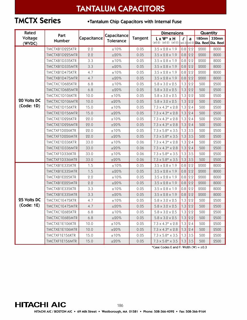
186
detaRegatloV)CDVW(
traPrebmuN
ecnaticapaCecnaticapaC
ecnareloTtnegnaT
RTK522D1BXTCMT 2.2 %01± 50.0 9.1x8.2x5.3 8.0 2.2 0002 0008
RTM522D1BXTCMT 2.2 %02± 50.0 9.1x8.2x5.3 8.0 2.2 0002 0008
RTK533D1BXTCMT 3.3 %01± 50.0 9.1x8.2x5.3 8.0 2.2 0002 0008
RTM533D1BXTCMT 3.3 %02± 50.0 9.1x8.2x5.3 8.0 2.2 0002 0008
RTK574D1BXTCMT 7.4 %01± 50.0 9.1x8.2x5.3 8.0 2.2 0002 0008
RTM574D1BXTCMT 7.4 %02± 50.0 9.1x8.2x5.3 8.0 2.2 0002 0008
RTK586D1CXTCMT 8.6 %01± 50.0 5.2x2.3x8.5 3.1 2.2 005 0052
RTM586D1CXTCMT 8.6 %02± 50.0 5.2x2.3x8.5 3.1 2.2 005 0052
RTK601D1CXTCMT 0.01 %01± 50.0 5.2x2.3x8.5 3.1 2.2 005 0052
RTM601D1CXTCMT 0.01 %02± 50.0 5.2x2.3x8.5 3.1 2.2 005 0052
RTK651D1EXTCMT 0.51 %01± 50.0 8.2x*3.4x3.7 3.1 4.2 005 0052
RTM651D1EXTCMT 0.51 %02± 50.0 8.2x*3.4x3.7 3.1 4.2 005 0052
RTK622D1EXTCMT 0.22 %01± 50.0 8.2x*3.4x3.7 3.1 4.2 005 0052
RTM622D1EXTCMT 0.22 %02± 50.0 8.2x*3.4x3.7 3.1 4.2 005 0052
RTK622D1FXTCMT 0.22 %01± 50.0 5.3x*8.5x3.7 3.1 5.3 005 0052
RTM622D1FXTCMT 0.22 %02± 50.0 5.3x*8.5x3.7 3.1 5.3 005 0052
RTK633D1EXTCMT 0.33 %01± 60.0 8.2x*3.4x3.7 3.1 4.2 005 0052
RTM633D1EXTCMT 0.33 %02± 60.0 8.2x*3.4x3.7 3.1 4.2 005 0052
RTK633D1FXTCMT 0.33 %01± 60.0 5.3x*8.5x3.7 3.1 5.3 005 0052
RTM633D1FXTCMT 0.33 %02± 60.0 5.3x*8.5x3.7 3.1 5.3 005 0052
RTK533E1BXTCMT 5.1 %01± 50.0 9.1x8.2x5.3 8.0 2.2 0002 0008
RTM533E1BXTCMT 5.1 %02± 50.0 9.1x8.2x5.3 8.0 2.2 0002 0008
RTK522E1BXTCMT 2.2 %01± 50.0 9.1x8.2x5.3 8.0 2.2 0002 0008
RTM522E1BXTCMT 2.2 %02± 50.0 9.1x8.2x5.3 8.0 2.2 0002 0008
RTK533E1BXTCMT 3.3 %01± 50.0 9.1x8.2x5.3 8.0 2.2 0002 0008
RTM533E1BXTCMT 3.3 %02± 50.0 9.1x8.2x5.3 8.0 2.2 0002 0008
RTK574E1CXTCMT 7.4 %01± 50.0 5.2x2.3x8.5 3.1 2.2 005 0052
RTM574E1CXTCMT 7.4 %02± 50.0 5.2x2.3x8.5 3.1 2.2 005 0052
RTK586E1CXTCMT 8.6 %01± 50.0 5.2x2.3x8.5 3.1 2.2 005 0052
RTM586E1CXTCMT 8.6 %02± 50.0 5.2x2.3x8.5 3.1 2.2 005 0052
RTK601E1EXTCMT 0.01 %01± 50.0 8.2x*3.4x3.7 3.1 4.2 005 0052
RTM601E1EXTCMT 0.01 %02± 50.0 8.2x*3.4x3.7 3.1 4.2 005 0052
RTK651E1FXTCMT 0.51 %01± 50.0 5.3x*8.5x3.7 3.1 5.3 005 0052
RTM651E1FXTCMT 0.51 %02± 50.0 5.3x*8.5x3.7 3.1 5.3 005 0052
TANTALUM CAPACITORS
AICHITACHI AIC / BOSTON AIC • 69 Milk Street • Westborough, MA 01581 • Phone: 508-366-4092 • Fax: 508-366-9164
TMCTX Series •Tantalum Chip Capacitors with Internal Fuse
*Case Codes E and F: Width (W) = ±0.3
Dimensions L x W* x H l a(±0.2) (±0.2) (±0.2) (±0.3) (±0.2)
Quantity180mm
Dia. Reel330mm
Dia. Reel
20 Volts DC(Code: 1D)
25 Volts DC(Code: 1E)

187
detaRegatloV)CDVW(
traPrebmuN
ecnaticapaCecnaticapaC
ecnareloTtnegnaT
RTK501V1BXTCMT 0.1 %01± 40.0 9.1x8.2x5.3 8.0 2.2 0002 0008
RTM501V1BXTCMT 0.1 %02± 40.0 9.1x8.2x5.3 8.0 2.2 0002 0008
RTK551V1CXTCMT 5.1 %01± 50.0 5.2x2.3x8.5 3.1 2.2 005 0052
RTM551V1CXTCMT 5.1 %02± 50.0 5.2x2.3x8.5 3.1 2.2 005 0052
RTK522V1CXTCMT 2.2 %01± 50.0 5.2x2.3x8.5 3.1 2.2 005 0052
RTM522V1CXTCMT 2.2 %02± 50.0 5.2x2.3x8.5 3.1 2.2 005 0052RTK533V1CXTCMT 3.3 %01± 50.0 5.2x2.3x8.5 3.1 2.2 005 0052RTM533V1CXTCMT 3.3 %02± 50.0 5.2x2.3x8.5 3.1 2.2 005 0052
RTK586V1EXTCMT 8.6 %01± 50.0 8.2x*3.4x3.7 3.1 4.2 005 0052
RTM586V1EXTCMT 8.6 %02± 50.0 8.2x*3.4x3.7 3.1 4.2 005 0052
RTK601V1FXTCMT 0.01 %01± 50.0 5.3x*8.5x3.7 3.1 5.3 005 0052
RTM601V1FXTCMT 0.01 %02± 50.0 5.3x*8.5x3.7 3.1 5.3 005 0052
RTK501H1CXTCMT 0.1 %01± 40.0 5.2x2.3x8.5 3.1 2.2 005 0052
RTM501H1CXTCMT 0.1 %02± 40.0 5.2x2.3x8.5 3.1 2.2 005 0052
RTK551H1CXTCMT 5.1 %01± 50.0 5.2x2.3x8.5 3.1 2.2 005 0052
RTM551H1CXTCMT 5.1 %02± 50.0 5.2x2.3x8.5 3.1 2.2 005 0052
RTK533H1EXTCMT 3.3 %01± 50.0 8.2x*3.4x3.7 3.1 4.2 005 0052
RTM533H1EXTCMT 3.3 %02± 50.0 8.2x*3.4x3.7 3.1 4.2 005 0052
RTK574H1FXTCMT 7.4 %01± 50.0 5.3x*8.5x3.7 3.1 5.3 005 0052
RTM574H1FXTCMT 7.4 %02± 50.0 5.3x*8.5x3.7 3.1 5.3 005 0052
TANTALUM CAPACITORS
AICHITACHI AIC / BOSTON AIC • 69 Milk Street • Westborough, MA 01581 • Phone: 508-366-4092 • Fax: 508-366-9164
TMCTX Series •Tantalum Chip Capacitors with Internal Fuse
Dimensions L x W* x H l a(±0.2) (±0.2) (±0.2) (±0.3) (±0.2)
Quantity180mm
Dia. Reel330mm
Dia. Reel
35 Volts DC(Code: 1V)
50 Volts DC(Code: 1H)
*Case Codes E and F: Width (W) = ±0.3

188
TANTALUM CAPACITORS
AICHITACHI AIC / BOSTON AIC • 69 Milk Street • Westborough, MA 01581 • Phone: 508-366-4092 • Fax: 508-366-9164
TMCN Series •High Performance Polymer Type Tantalum Chip Capacitors
The TMCN Series reduces USR by using high performancepolymer based on Hitachi’s original manufacturingprocess.
The TMCN is most suitable for an output smoothingcircuit that is used, for example, in a DC-DC converterrequiring a small size, large capacitance, and low ESR.
Jan
n
A
N
a
Feb
p
B
P
b
Mar
q
C
Q
c
Sep
w
J
W
j
Aug
v
H
V
h
Jul
u
G
U
g
Jun
t
F
T
f
May
s
E
S
e
Apr
r
D
R
d
Dec
n
M
Z
m
Nov
n
L
Y
l
Oct
n
K
X
k
Month
Year
2000
2001
2002
2003
Tantalum Capacitor Date Code Table
Outline Drawings and Dimensions
Anode Indication belt mark
TMCN Case Code Table
CaseCode
P
A
B
L ±0.2
2.0
3.2
3.5
Dimensions
W ±0.2
1.25
1.6
2.8
H ±0.2
1.2
1.6
1.9
l ±0.3
0.5
0.7
0.8
a ±0.2
0.9
1.2
2.0
detaRegatloV)CDVW(
traPrebmuN
ecnaticapaCecnaticapaC
ecnareloTtnegnaT
RTM601G0PNCMT 0.01 %02± 10.0 2.1x52.1x0.2 5.0 9.0 0003 A/N
RTM651GOANCMT 0.51 %02± 10.0 6.1x6.1x2.3 7.0 2.1 0002 0008
RTM622G0ANCMT 0.22 %02± 10.0 6.1x6.1x2.3 7.0 2.1 0002 0008
RTM574J0PNCMT 7.4 %02± 10.0 2.1x52.1x0.2 5.0 9.0 0003 A/N
RTM601J0ANCMT 0.01 %02± 10.0 6.1x6.1x2.3 7.0 2.1 0002 0008
RTM651J0ANCMT 0.51 %02± 10.0 6.1x6.1x2.3 7.0 2.1 0002 0008
RTM622J0BNCMT 0.22 %02± 10.0 9.1x8.2x5.3 8.0 2.2 0002 0008
RTM633J0BNCMT 0.33 %02± 10.0 9.1x8.2x5.3 8.0 2.2 0002 0008
RTM674J0BNCMT 0.22 %02± 10.0 9.1x8.2x5.3 8.0 2.2 0002 0008
RTM574A1ANCMT 7.4 %02± 10.0 6.1x6.1x2.3 7.0 2.1 0002 0008
Dimensions L x W* x H l a(±0.2) (±0.2) (±0.2) (±0.3) (±0.2)
Quantity180mm
Dia. Reel330mm
Dia. Reel
4 Volts DC(Code: 0G)
6.3 Volts DC(Code: 0J)
10 Volts DC(Code: 1A)
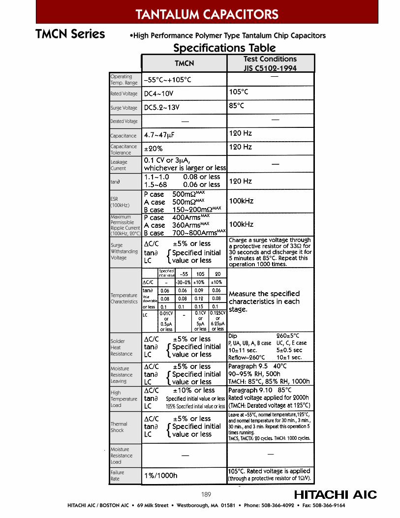
189
TANTALUM CAPACITORS
AICHITACHI AIC / BOSTON AIC • 69 Milk Street • Westborough, MA 01581 • Phone: 508-366-4092 • Fax: 508-366-9164
TMCN Series •High Performance Polymer Type Tantalum Chip Capacitors
Specifications Table
OperatingTemp. Range
Rated Voltage
Surge Voltage
Derated Voltage
Capacitance
CapacitanceTolerance
LeakageCurrent
tan∂
SurgeWithstandingVoltage
TemperatureCharacteristics
SolderHeatResistance
MoistureResistanceLeaving
HighTemperatureLoad
ThermalShock
MoistureResistanceLoad
FailureRate
ESR(100kHz)
MaximumPermissibleRipple Current(100kHz, 20°C)
TMCN Test ConditionsJIS C5102-1994