TMC TMC Transformers. Cast Resin Transformer (CRT) History • Cast resin transformers first...
59
TMC Transformers TMC Product & Technology Presentation
Transcript of TMC TMC Transformers. Cast Resin Transformer (CRT) History • Cast resin transformers first...

TMC Transformers
TMC Product & Technology Presentation

TMC Transformers

TMC Transformers
Cast Resin Transformer (CRT) History
• Cast resin transformers first appeared in Germany during the 1960s. This new style of dry type transformer was developed with HV windings cast under vacuum in an epoxy resin compound filled with inert silica.
• The main advantages of this cast epoxy resin transformer included its self-extinguishing characteristics in case of fire, an increased electrical insulation level and the absence of special installation procedures when compared to the typical dry type transformer.
• The new transformer immediately became an ideal alternative to dry machines with “open” windings, and from the beginning it demonstrated a high reliability. By the early 1980s, cast resin transformers were being produced in large numbers and in a few years, they surpassed all other solutions in installations where fire risk was of paramount concern.
• Nowadays the cast resin transformer is the most widely specified solution for installations in fire risk areas, because there are no pollution or flammability risks from any liquid spillage.
• Other main advantages of using a cast resin transformer are its high reliability, safety, and
minimum maintenance requirements.
• The best indication of their reliability is demonstrated by the millions of cast resin transformers installed worldwide in the most sensitive plants and installations such as nuclear plants, petroleum platforms, ships, petrochemical plants, civil and military structures, harbours, airports, underground mines - wherever safety is paramount.

TMC Transformers
History of TMC
• TMC was established in Australia in 1936 as a specialist manufacturer of
high voltage transformers. In 2014 its manufacturing facilities in Spain and Australia are endowed with over 75 years of uninterrupted experience in the manufacture of a wide range of electrical induction equipment.
• The group has excelled at providing high quality products to the electrical power industry worldwide, with an emphasis on meeting exacting specifications and standards, whilst minimising cost.
• TMC is fully accredited to the international quality standard ISO9001, and continues to build on a tradition of product excellence and customer focus and satisfaction.

TMC Transformers
• Rated Power from 100 to 30000 kVA
• Rated Voltage to class 72 kV
• HV windings vacuum cast in moulds
• LV windings vacuum/pressure cast
• Designs for Special Applications
• Designs for extreme ambient conditions
• High resistance to short circuit stress
• High resistance to seismic phenomena
• Linear lightning impulse distribution in windings
• Three or single phase construction
• Multi winding transformers
Range and Standard Designs

TMC Transformers
• Distribution transformers
• Traction transformers
• Marine and offshore transformers
• Sub-station transformers with on-load tap changer
• Renewable energy transformers (Wind Farms / Photovoltaic)
• Rectifier transformers (12, 18, 24, 36, 72, 144 pulse and up)
• Transformers for paint plant (silicone free on demand)
• Induction oven transformers
• Earthing transformers
• Autotransformers
Application List

TMC Transformers
• Power and Distribution
• Rectifier
• Earthing
• Motor Starting
Cast Resin Transformer Application List

TMC Transformers
• Shunt
• Current Limiting
• Damping (Inrush)
• Tuning (Filtering)
• Smoothing
• Neutral Earthing
Reactor Application List

TMC Transformers
CHARACTERISTICS OIL TRANSFORMERS
DRY TYPE
CAST RESIN
Flammability YES NO NO Self-extinguishing in case of electrical damage or failure NO YES YES Necessity of anti-fire structures such as oil bunds and fire walls YES NO NO Hygroscopicity of insulating materials NO YES NO Environmental pollution YES NO NO Resistance stability to short circuit phenomena NO NO YES Energizing special procedures NO YES NO Maintenance required YES YES NO Environmental pollution risk due to liquid losses YES NO NO Ability to withstand humid, saline and tropical environments YES NO YES Installation close to the load-centre and consequent reduction of plant and management costs NO NO YES
Reliability without maintenance and minimal requirement for specialised labour for installation. NO NO YES
Finished Products to withstand high, immediate and short overloads owing to reduced current density and high thermal factor (excellent for Rail application)
NO NO YES
Product Comparisons

TMC Transformers
High short circuit withstand
High resistance to cold ambient
Efficient cooling of LV winding
High Impulse withstand
High mechanical resistance
Special resilient coil supports
Low PD level in windings
Tinned LV busbar terminals
Main Characteristics of Cast Resin Transformers

TMC Transformers
Components
• CORE
• HV WINDING
• LV WINDING
• CASTING
• ENCLOSURE

TMC Transformers
• TMC magnetic cores are manufactured using high-permeability and low-loss grain-oriented silicon steel sheets. The insulated surface of these sheets minimizes power loss due to stray currents.
• The core components are assembled on special workbenches in order to prevent any deformation of the individual sheets, and assure perfect core alignment.
• The joints are mitre cut at 45° and laminations are stacked step–lap type to minimize stray-flux losses and to prevent joint vibration, which is one of the primary causes of noise. The overlap of each single lamination results in high mechanical strength and consequent reduction of noise level.
• Corrosion protection of the assembled core against the effects of external environmental agents is obtained by a final application of a full coating of bi-component epoxy resin.
Step lap
Core

TMC Transformers
HV Winding Characteristics
TMC Transformers
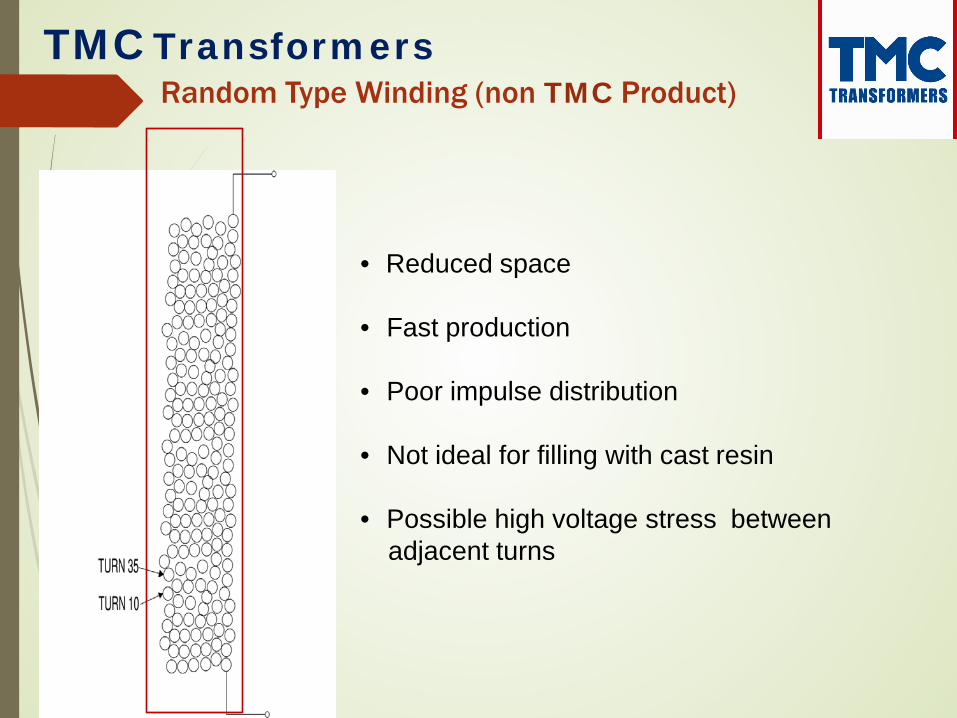
• Reduced space • Fast production • Poor impulse distribution
• Not ideal for filling with cast resin • Possible high voltage stress between
adjacent turns
Random Type Winding (non TMC Product)

TMC Transformers
Turn n.1
Turn n.16
• Usually reduced number of discs (wire has is own insulation on surface)
• Poor impulse distribution
• Inefficient to fill with cast resin
• High voltage between layers in normal operation
• Non linear voltage between turns during impulse
Wire disc type winding (non TMC product)
TMC Transformers
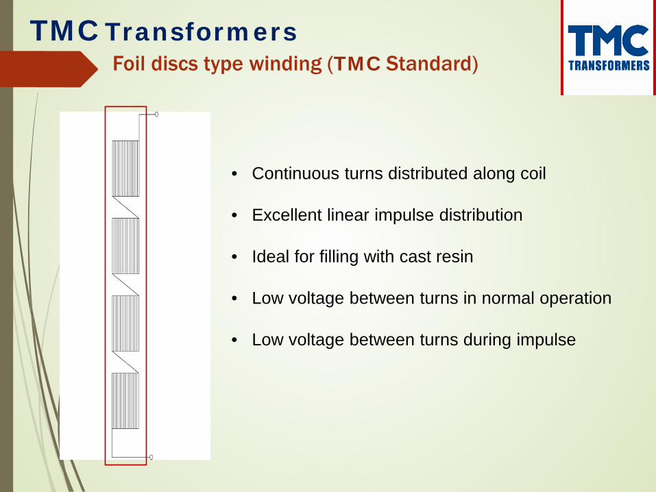
• Continuous turns distributed along coil
• Excellent linear impulse distribution
• Ideal for filling with cast resin
• Low voltage between turns in normal operation
• Low voltage between turns during impulse
Foil discs type winding (TMC Standard)

TMC Transformers
TMC Foil disc type winding machine

TMC Transformers
TMC Homogeneous distribution
Wire type Non Homogeneous distribution
HV Coil Voltage Distribution

TMC Transformers
• To be adjusted with transformer de-energized
• Typical regulation of HV voltage is with 5 steps
• Usually these steps are ± 2 x 2,5%
• With TMC standard moulds up to 9 steps are possible
HV Voltage Tappings

TMC Transformers
• Pre-heating to remove humidity
• Three steps processing of resin to blend the components
(filler, hardener, resin, alumina)
• Casting under vacuum
• Gelling procedure (vacuum plant and oven)
• Hardening procedure (oven) Physical parameters of all steps are traced and recorded
Casting Process

TMC Transformers
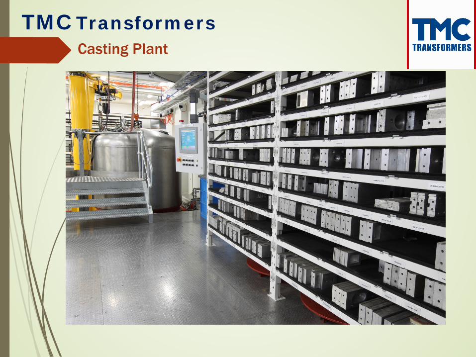
Casting Plant
TMC Transformers
Casting Plant

TMC Transformers
LV Winding:
• Winding conductor is high conductivity aluminium foil
• Busbar terminals are fusion welded during the winding process
• Finished coil is vacuum impregnated in two pack high temperature polyester resin
The Advantages:
• Insulation against humidity • Withstand high short circuit • Optimal temperature distribution in the coil • Reduction of additional losses
LV Winding Characteristics (TMC Standard)

TMC Transformers
LV winding cast in moulds in epoxy resin:
• Compact and strong
• Terminals welded during transformer assembly
• Ultimate insulation against humidity
• Ultimate short circuit and seismic withstand strength
• Satisfactory temperature distribution
LV Winding Characteristics (TMC Optional)
TMC Transformers
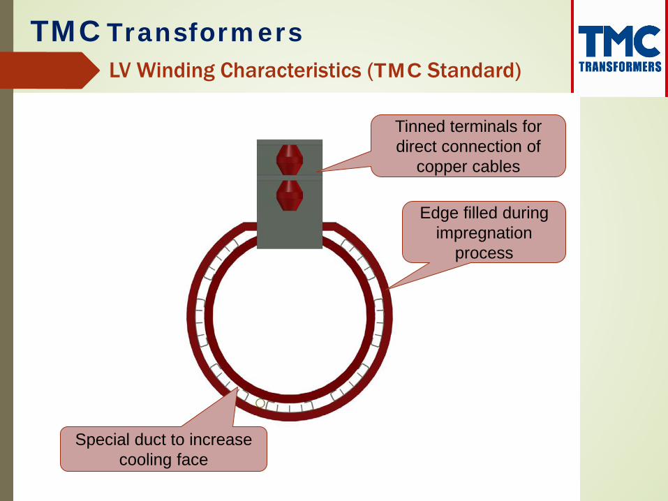
Edge filled during impregnation
process
Special duct to increase cooling face
Tinned terminals for direct connection of
copper cables
LV Winding Characteristics (TMC Standard)

TMC Transformers
LV Winding Machine

TMC Transformers
Aluminium cooling ducts
Terminal fusion welded along full length of foil
winding conductor
Bushings fixed to core clamps
Line terminal
LV Winding Characteristics (TMC Standard)

TMC Transformers
Vacuum Pressure Impregnation

TMC Transformers
Vacuum Pressure Impregnation

TMC Transformers
• Degree of Protection Provided by Enclosures
• The “IP Code”
• Common requests:
IP00 No enclosure IP21 For indoor, clean, dry environment IP22 For extra water protection (sprinklers) IP33 Can be used outdoor IP43 Outdoor environment IP54 Harsh or extreme outdoor environments IP66 Extremely harsh environments (Nitrogen filled)
Enclosure Protection

TMC Transformers
Tests prescribed from IEC 60076-11 2004 :
• Measurement of winding resistance
• Measurement of voltage ratio and check for phase displacement
• Measurement of short circuit impedance and load losses
• Measurement of no load losses and current
• Separate source AC withstand voltage test • Induced AC withstand voltage test (2 times
nominal voltage)
• Measurement of partial discharge
Routine Tests Performed on all Transformers

TMC Transformers
Test Facility

TMC Transformers
• Lighting Impulse Test
• Temperature Rise Test
• Sound Level Measurement The relevant requirements of IEC 60076-10 apply.
Sound level guarantees are based on free field conditions and apparent increases in sound level may be noted on site due to reflections from the hard building walls, floor and ceiling.
• Short Circuit Test (Test Performed at Ausgrid Laboratory)
• E2C2F1 – IEC 60076-11 2004 (No longer on prototype, but on standard F-F design)
Type Tests (on request)
Special Tests (on request)

TMC Transformers
Environmental Classes Environmental conditions for dry-type transformers are identified in terms of humidity, condensation, pollution and ambient temperature. Class E0: No condensation is expected to occur on the transformer and pollution is negligible. This is commonly achieved in a clean, dry indoor installations. Class E1: Occasional condensation may occur on the transformer (for example, when the transformer is de-energised). Limited pollution is possible Class E2: Frequent condensation or heavy pollution or combination of both may occur.
Special Test E2

TMC Transformers
Climatic Classes Two climatic classes are defined: Class C1: The transformer is suitable for operation at ambient temperature not below –5°C but may be exposed during transport and storage to ambient temperatures down to –25°C Class C2: The transformer is suitable for operation, transport and storage at ambient temperatures down to –25°C NOTE Transformers mounted outdoors should be housed in an adequate enclosure or be given other suitable protection.
Special Test C2

TMC Transformers
Fire Behaviour Classes Two fire behaviour classes are defined: Class F0: There is no special fire risk to consider. Except for the characteristics inherent in the design of the transformer, no special measures are taken to limit flammability. Nevertheless, the emission of toxic substances and opaque smoke shall be Minimized. Class F1: Transformer will be subject to a fire hazard. Restricted flammability is required. The emission of toxic substances and opaque smoke shall be minimized.
Special Test F1

TMC Transformers
Finished Products
2000kVA 11000/433V Cast Resin Transformer, AN IP43 with MCCB on LV 31464

TMC Transformers
Finished Products
2000kVA 11000/433V Cast Resin Transformer, AN IP00 31464

TMC Transformers
Finished Products
1500kVA 11000/433V Cast Resin Transformer, AN IP43 SS316 31453

TMC Transformers
Finished Products
4MVAr 33kV Capacitor Bank with 41.3mH 33kV 75A Filter Reactor , AN IP43 31080

TMC Transformers
Finished Products
3000kVA 11000-6600/600-600V Cast Resin Transformer, AN IP43 30970

TMC Transformers
Finished Products
2800kVA 22000/1700-1700V Cast Resin Transformer, AN IP21 1 of 12 in a 144 Pulse System 31228

TMC Transformers
Finished Products
1750kVA 6600/1910V 36 Pulse Cast Resin Transformer, AN IP00 31425

TMC Transformers
Finished Products
1171kW 11kV Motor Starting Auto-Transformer, AN IP00 31047

TMC Transformers
Finished Products
6.6kV 400A/10s ZN0 Neutral Earthing Transformer, AN IP31 31452
TMC Transformers
Finished Products
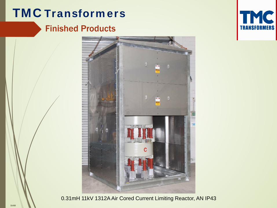
0.31mH 11kV 1312A Air Cored Current Limiting Reactor, AN IP43 31430

TMC Transformers
Finished Products
350kVAr 440V 459A Iron Shroud Reactor, AN IP21 31326

TMC Transformers
Finished Products
72kVAr 415V 100A Iron Cored Reactor, AN IP21 30834

TMC Transformers
Finished Products
415V 125A 0.17mH Air Cored Current Limiting Reactor, AN IP21 31560

TMC Transformers
Finished Products
1500kVA 11000/1100V Dyn11 GNAN IP66 30696

TMC Transformers
Finished Products
1250kVA 11000/433V Dyn11 ANAN IP66 with HV Isolator 31391

TMC Transformers
Finished Products
1500kVA 11000/433V Dyn11 ANAN IP66 31384

TMC Transformers
Finished Products
1000kVA 11000/1000V Dyn11 GNAN IP66 31347

TMC Transformers
Finished Products
3000kVA 11000/3300V Dyn11 GNAN IP66 31338

TMC Transformers
Finished Products
4500kVA 11000/3300V Dyn11 GNAN IP66 31494

TMC Transformers
Finished Products
6000kVA 11000/33300/1100V Dyn11yn11 GNAN IP66 31232

TMC Transformers
Installations
2000kVA 11000/690V Cast Resin Transformer, AN IP43 Material Handling Plant

TMC Transformers
Installations
Carlo Vaccari 2000kVA 22000/433V Cast Resin Transformer, AN IP21 Data Centre
27214

TMC Transformers
Installations
Carlo Vaccari 2500kVA 11000-6600/600-600V Cast Resin Transformer AN IP43 on a Mine Shovel