bodylang. · mermaid 200/ tm top 59/ tm btm 211/ tm 60/6,' tm top btm 201,' tm top 30/ tm slingshot
Upload
enrique-sandovalCategory
view
7download
2
TMTM--U675U675--011011 Troubleshooting Guide.Troubleshooting Guide.
Please use the following flowcharts to help you to diagnose what is wrong with your printer. When the flowcharts call for a product to be returned to PC-PoS, please contact PC-PoS before the unit is sent back. Some of the following flowcharts discuss changing the Dip switch settings so that they are appropriate for the intended application. If you are not fully conversant with doing this then either contact your local dealer or contact the PC-PoS technical support department nearest to you. These flowcharts are intended as a basic fault-finding guide only and we do not encourage any repair to the internal mechanisms or electronic components by non- PC-PoS technical staff as this will render the warranty invalid. If you have any questions regarding this matter then please contact PC-PoS.

The Basic Guide.
Start
Is the POWER LED lit?
Power On
Go to part 1.
No
Is the PAPER OUT
LED lit?
Yes
No
Is the ERROR LED lit?
Yes
Go to part 4.
Yes
Is the ERROR LED flashing?
Go to part 4. (See also at the end of
this guide)
Yes
No
No
Execute the self-test (See part 4for details on how to do this).
Is the self-test normal?
Is the printout normal?
Terminal sends print data
Go to part 7.
END
No
No
Yes
Yes
Is the paper roll not loaded or near roll end?
Load roll paper.
OK?
END
Yes
No No
Yes
Go to part 6.
Go to part 2.
Is Paper Loading Correctly?
Go to part 5.
Yes
No
Is the SLIP LED lit or Flashing?
Go to part 3.
Yes
No

Part 1. Power LED does not light.
Start
Is the power supply cable connected
properly?
Connect power supply cable properly. To make certain this is done, remove the connector completely and re-insert.
OK?
Is the Power supply OK? I.E has it been
tested on another device?
Connect supply to another known working printer and test it.
PSU OK?
Check Fuse in mains plug and check for damage to cable or connector. Re-test the Power Supply on
another unit before proceeding. If you had to change the fuse and start the main flow-chart again.
PSU OK?
Return unit to PC-PoS. Beyond Local Repair.
END
No
Yes
Yes
Yes
Yes
Yes
No
No
No
No

Part 2. Paper Out LED is lit.
No
Yes
Start
Turn the printer off for 30 seconds and then turn back
on again.
OK?
END
Yes
No
Is the cover closed correctly?
Close the cover correctly. The best way to do this is to open the cover and then closing it again fully making certain to feed the paper
properly.
OK?
END
Yes
No
Return unit to PC-PoS. Beyond Local Repair.
END

Part 3. SLIP LED lit or flashing.
No
Yes
Start
Turn the printer off for 30 seconds and then turn back
on again.
OK?
END
Yes
No
Is the cover closed correctly?
Close the cover correctly. The best way to do this is to open the cover
and then closing it again fully.
OK?
END
Yes
No
Return unit to PC-PoS. Beyond Local Repair.
END

Part 4. Error LED is Lit or Flashing.
Start
Are the connectors to the printer hooked up
correctly?
Hook up connectors correctly. The easiest way to do this is to remove the connectors, while the power is off,
and re-connect them.
OK?
END
Yes
No
Is the paper type selected correctly by
DIP switch?
Turn the printer power off and change the DIP switch settings to the proper setting for the type of paper being used. (See the end of this document for the
appropriate settings)
OK?
END
Yes
No
Has the printer recovered from
the error?
Reset the printer by switching it off for at least 30 seconds.
Wait for the print head temperature to drop if excessive.
Return unit to PC-PoS. Beyond Local Repair.
END
No
No
Yes
Yes

Part 4. Paper is not Loading Correctly.
No
Yes
Start
Is paper jammed in the paper inlet path or anywhere
in the printer?
Remove the paper jam. The best way to do this is to take out ALL paper rolls from the printer and then clean the inside to make
certain that all debris is removed. Re-load paper when finished and re-test.
OK?
END
Yes
No
Return unit to PC-PoS. Beyond Local Repair.
END

Part 6. Self-test is not normal.
The Self-Test. To initiate the self-test for the RECEIPT part of the printer, follow these instructions: 1. Make certain there is either a paper roll or a label roll inserted and loaded into the
printer before starting. 2. Turn off the printer using the power button. 3. Turn the printer on while keeping the FEED button depressed. The self-test
should now start and the information printed will give the status of the printer. 4. When the test print is complete, the following will be on the last line of print,
“Self-test printing, Please press FEED button.” The PAPER OUT LED flashes to indicate the standby condition.
5. Press the FEED button to continue the self-test or switch the printer off and then back on again to resume normal printing.
To initiate the self-test for the SLIP part of the printer, follow these instructions: 1. Turn off the printer using the power button. 2. Turn the printer on while keeping the RELEASE button depressed. The SLIP
LED should now be flashing. Insert a piece of paper into the slip printing area then printing will commence and the information printed will give the status of the printer.
3. When printing is complete, the SLIP LED will be flashing. To continue the self-test, insert more paper in the slip part of the printer or switch off and back on again to resume normal printing.

Part 6 cont. Self-test is not normal.
Start
Does the printer operate at all?
Is the cover closed properly?
Close cover properly.
OK?
END
Yes
No
Return unit to PC-PoS. Beyond Local Repair.
Printing is carried out, but print quality is deficient or
paper feeding is not normal.
Is the Ink Ribbon installed correctly?
Does it have enough ink?
OK?
END
Yes
Install print ribbon correctly or change print ribbon for a new one.
Return unit to PC-PoS. Beyond Local Repair.
No
No
No
Yes
Yes
Yes
No

Part 7A (Serial Version) Data from host is not printed normally.
Start
Set SW1 of DIP switch bank 1 to OFF.
Send data from host to printer.
Is “?” printed?
Are RS-232 interface parameters set to
identical values at host printer?
Make settings identical
OK?
END
Yes
No
Does interface cable match
specifications? Replace with a proper
cable
OK?
END
Yes No
Is the interface cable damaged or
broken? Replace interface
cable.
OK?
END
Yes No
Return unit to PC-PoS. Beyond Local Repair.
Yes
Yes
Yes
Yes
No
No
No
No

Part 7B (Parallel Version) Data from host is not printed normally.
Start
Send data from host to printer.
Is “?” printed?
Are RS-232 interface parameters set to
identical values at host printer?
Make settings identical
OK?
END
Yes
No
Does interface cable match
specifications? Replace with a proper
cable
OK?
END
Yes No
Is the interface cable damaged or
broken? Replace interface
cable.
OK?
END
Yes No
Return unit to PC-PoS. Beyond Local Repair.
Yes
Yes
Yes
Yes
No
No
No
No

DIP Switch Settings for the TM-U675-011
For the Serial interface model. TM-U675 DIP switch 1
SW-1 Function ON OFF 1 Data reception error Ignored Prints ‘?’ 2 Receive buffer capacity 45 bytes 4K bytes 3 Handshaking XON/ XOFF DTR/ DSR 4 Word Length 7 bits 8 bits 5 Parity check Enabled Disabled 6 Parity selection Even Odd 7 8
Transmission speed selection. See the table below.
Transnission Speed (BPS) SW 1-7 SW 1-8 2400 ON ON 4800 OFF ON 9600 ON OFF 19200 OFF OFF
TM-U675 switch 2 SW-2 Function ON OFF
1 Handshaking Operation (Busy Condition)
Receive Buffer Full Off-line or Receive buffer Full
2 Connection of Customer Display Connected Not Connected 3 Selects number of characters per line See Table Below. 4 TM-U375 Compatibility Compatible Not Compatible 5 6
For Internal Use Only. Not to be changed.
7 I/F Pin 6 reset signal Enabled Disabled 8 I/F Pin 25 reset signal Enabled Disabled
TM-U675 Characters Per Line SW 2-4 SW 2-3 Font Type/ Character
Dot Spacing Characters
Per Line Total Dots
5 x 9 / 2 Half dots 33 Columns OFF 7 x 9 / 3 Half dots 40 Columns
400 Half Dots
5 x 9 / 1 Half dots 35 Columns On ON
5 x 9 / 2 Half dots 42 Columns 385 Half Dots
Note: Do not change the DIP switch settings while the printer power is on. You may damage the printer.

DIP Switch Settings for the TM-U675-011
For the Parallel interface model. TM-U675P DIP switch 1
SW-1 Function ON OFF 1 Auto line feed Enabled Disabled 2 Receive buffer capacity 40 bytes 4K bytes 3 4 5 6 7 8
Reserved Fixed to OFF
TM-U675P DIP switch 2
SW-2 Function ON OFF 1 Handshaking (Busy Condition) Receive Buffer Full Off Line or Receive Buffer
Full 2 Internal Use (DO NOT CHANGE) Fixed to OFF 3 Characters per line See Table Below 4 TM-U375 Compatibility Compatible Not Compatible 5 6
Internal Use Fixed to OFF
7 Cannot Be Used (Only for serial interface model) Fixed to OFF
8 I/F pin 31 reset signal (DO NOT CHANGE SETTING)
Fixed to ON
TM-U675 Characters Per Line SW 2-4 SW 2-3 Font Type/ Character
Dot Spacing Characters
Per Line Total Dots
5 x 9 / 2 Half dots 33 Columns OFF
7 x 9 / 3 Half dots 40 Columns 400 Half Dots
5 x 9 / 1 Half dots 35 Columns On
ON 5 x 9 / 2 Half dots 42 Columns
385 Half Dots
Note: Do not change the DIP switch settings while the printer power is on. You may damage the printer.
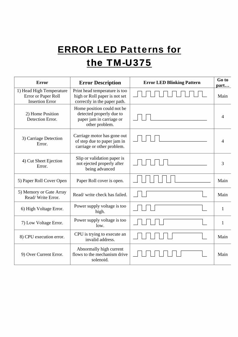
ERROR LED Patterns for the TMthe TM--U375U375
Error Error Description Error LED Blinking Pattern
Go to part…
1) Head High Temperature Error or Paper Roll
Insertion Error
Print head temperature is too high or Roll paper is not set correctly in the paper path.
Main
2) Home Position Detection Error.
Home position could not be detected properly due to paper jam in carriage or
other problem.
4
3) Carriage Detection Error.
Carriage motor has gone out of step due to paper jam in carriage or other problem.
4
4) Cut Sheet Ejection Error.
Slip or validation paper is not ejected properly after
being advanced
3
5) Paper Roll Cover Open Paper Roll cover is open.
Main
5) Memory or Gate Array Read/ Write Error.
Read/ write check has failed.
Main
6) High Voltage Error. Power supply voltage is too
high.
1
7) Low Voltage Error. Power supply voltage is too
low.
1
8) CPU execution error. CPU is trying to execute an
invalid address.
Main
9) Over Current Error. Abnormally high current
flows to the mechanism drive solenoid.
Main