Titan Fuel Bunker™, 12 Gallon, In-Bed Transfer Fuel System ... · 14 Titan Fuel Bunker Tank Lid 1...
16
TITAN Fuel Bunker™ Installation Instructions, Part No. 99 0000 0947 Page: 1 TITAN pt. no.: 99 0000 0947 Important: Please read these instructions carefully and completely before starting the installation. TITAN Fuel Tanks™ INSTALLATION INSTRUCTIONS Titan Fuel Bunker™, 12 Gallon, In-Bed Transfer Fuel System for UTV Congratulations! You have purchased the finest UTV fuel system on the market. It has been designed to be attractive, durable and simple to install. It includes a custom designed 3 gallon per minute (GPM) fuel pump, as well as a lockable storage pocket to keep your refueling time low and your valuables safe. The durability of TITAN’s fine military grade, cross-linked polymer tank products is legendary. We routinely test our tanks using state-of-the-art computer simulations as well as actual drop tests. We fill our tanks completely and drop them 30 feet onto a steel plate--never losing a drop of liquid. There are no welds to fail. Soap and water and a little bit of Pledge® furniture spray, or Armor All® Protectant will keep your tank looking brand new. Pledge® is a registered trademark of S.C. Johnson & Son, Inc Armor All® is a registered trademark of Spectrum Brands. CALIFORNIA NOTICE:
Transcript of Titan Fuel Bunker™, 12 Gallon, In-Bed Transfer Fuel System ... · 14 Titan Fuel Bunker Tank Lid 1...

TITAN Fuel Bunker™ Installation Instructions, Part No. 99 0000 0947 Page: 1
TITAN pt. no.: 99 0000 0947
Important: Please read these instructions carefully and completely before starting the installation.
TITAN Fuel Tanks™
INSTALLATION INSTRUCTIONS
Titan Fuel Bunker™, 12 Gallon, In-Bed
Transfer Fuel System for UTV
Congratulations! You have purchased the finest UTV fuel system on the market. It has been designed to be attractive, durable and simple to install. It includes a custom designed 3 gallon per minute (GPM) fuel pump, as well as a lockable storage pocket to keep your refueling time low and your valuables safe.
The durability of TITAN’s fine military grade, cross-linked polymer tank products is legendary. We routinely test our tanks using state-of-the-art computer simulations as well as actual drop tests. We fill our tanks completely and drop them 30 feet onto a steel plate--never losing a drop of liquid. There are no welds to fail. Soap and water and a little bit of Pledge® furniture spray, or Armor All® Protectant will keep your tank looking brand new.
Pledge® is a registered trademark of S.C. Johnson & Son, Inc Armor All® is a registered trademark of Spectrum Brands.
CALIFORNIA NOTICE:

TITAN Fuel Bunker™ Installation Instructions, Part No. 99 0000 0947 Page: 2
Required Tools:
1 ea. Medium Phillips Screw Driver 1 ea. Tape Measure 1 ea. Wire Stripper 1 ea. Wire Connection Crimper 1 ea. Small Propane Torch or Cigarette Lighter 1 ea. Medium Strength Thread Locker (Blue)
Note: If you choose to use a power drill, be extremely careful. Excessive torque will spin the inserts out of the tank and render it useless.
Fig 1. Exploded view showing tank assembly Note: All tanks should come with these parts pre-assembled

TITAN Fuel Bunker™ Installation Instructions, Part No. 99 0000 0947 Page: 3
Item No. Part Description Qty.
1 Titan Fuel Bunker Tank Body 1
2 Draw Latch Catch 2
3 10-24 X 1" Phillips Screw 2
4 Rubber Foot 4
5 5/16-18 X .75" Phillips Screw 4
6 Grounding Stud Head 1
7 .3125-18 Hex Nut for Grounding Stud 1
8 12.75" Grounding Stud Shaft 1
9 Grounding Stud Gasket 1
10 Pump Nozzle 1
11 Electric Pump 1
12 Pump Grommet 1
13 Fuel Cap 1
14 Titan Fuel Bunker Tank Lid 1
15 1" Footman Loop 4
16 10 X .625" High Low Phillips Screw 8
17 Lid Gasket 1
18 Draw Latch 2
19 10 X 1.25" High Low Phillips Screw 4
20 1/2” PVC Fuel Hose, 7’8”, yellow 1
21 Inline Ball Valve 1
Mounting Configurations
The Fuel Bunker has been designed for use with multiple UTV models. Each model has a unique set of mounting hardware designed to work as closely as possible with OEM mounting methods. Note: Individual parts in the provided diagrams have been colored for clarity. These colors do not represent the actual part colors.
Tank Body Installation
I. Attach Mounting Hardware and Mount Tank
Step Description
1 Using Fig. 1, make sure the TITAN Fuel Bunker is completely assembled and missing no parts.
2 Follow the diagrams and provided instructions to attach the mounting hardware to the tank body. Be sure to follow the instructions for the specific UTV and matching hardware.

TITAN Fuel Bunker™ Installation Instructions, Part No. 99 0000 0947 Page: 4
RZR 900 (’15-’17), 4 900 (’14-’17), XP 900 (’11-’14), 4 XP 900 (’12-’14), 1000 (’16-’17), XP 1000 (’14-’17), 4 XP 1000 (’14-’17), XP Turbo (’16-’17):
Required tools: T27 size screw driver, Phillips head screw driver, Medium strength thread locker (blue)
Part Description Qty.
RZR Front Lock N Ride Mount 2
1/4"-20 X 1/2" Torx Pan Head Machine Screw, Black Zinc Plated Steel 4
RZR XP Rear Mount 2
1/4"-20 X 2-1/4" Phillips Pan Head Machine Screw, Black Zinc Plated Steel 4
5/16-18 Eyebolt, 1.75” shank 2
5/16” Fender Washer, 1.25” Diam 2
5/16-18 4 prong T Nut 2
Expansion Plug 2
Fig. 2. RZR 900, 1000, and XP Mounting Hardware
1. Using a Phillips head screw driver, attach the RZR XP Rear Mounts (lightgray) to the tank body using the (4) ¼”-20 x 2-1/4” Phillips screws andthread locker.
2. Using a T27 size screw driver, attach the (2) RZR Front Lock N RideMounts using the (4) ¼”-20 X ½” Torx screws and thread locker.
3. As shown in Fig. 3, attach the eyebolt, fender washer, expansion plug(orange) and T nut to the RZR Front Lock N Ride Mounts. The prongs ofthe T nut must extend up into the expansion washer. Tighten theassembly until the expansion plugs slide snugly into the bed holes.
4. Slide the tabs of the rear mounting feature into the slots in the backwall of the RZR bed, dropping the eyebolt assemblies into the availableholes in the bed of the RZR. Tighten the eyebolt assemblies until the Fig. 3. Eyebolt expansion plugs bulge and securely hold the tank in place. Assembly

TITAN Fuel Bunker™ Installation Instructions, Part No. 99 0000 0947 Page: 5
RZR 570 (’12-’17), 800 (’08-’14), 4 800 (’10-’14):
Required tools: T27 size screw driver, Medium strength thread locker (blue)
Part Description Qty.
RZR Front Lock N Ride Mount 2
1/4"-20 X 1/2" Torx Pan Head Machine Screw, Black Zinc Plated Steel 8
RZR 570 Rear Passenger Mount 1
RZR 570 Rear Driver Mount 1
5/16-18 Eyebolt, 1.75” shank 4
5/16” Fender Washer, 1.25” Diam. 4
5/16-18 4 prong T Nut 4
Expansion Plug 4
Fig. 4. RZR 570 and 800 mounting hardware
1. Using a T27 size screw driver, attach the RZR Rear Passenger Side and Driver Side Mountsusing thread locker and (2) ¼”-20 X ½” Torx screws each. Note that these brackets looksimilar, but are mirror images of each other. Orient the mounts so the hole is as far to theback of the tank as possible.
2. Using a T27 size screw driver, attach the (2) RZR Front Lock N Ride Mounts using threadlocker and the (4) ¼”-20 X ½” Torx screws.
3. As shown in Fig. 3 (previous), attach the eyebolt, fender washer, expansion plug (orange)and T nut to the RZR Front Lock N Ride Mounts. The prongs of the T nut must extend upinto the expansion washer. Tighten the assembly until the expansion plugs slide snugly intothe bed holes.
4. Gently drop the tank onto the bed of the UTV, making sure all 4 eyebolt assemblies dropinto the available holes in the bed of the RZR. Tighten the eyebolt assemblies until theexpansion plugs bulge and securely hold the tank in place.

TITAN Fuel Bunker™ Installation Instructions, Part No. 99 0000 0947 Page: 6
Can Am Maverick:
Required tools: T27 size screw driver, Medium strength thread locker (blue)
Part Description Qty.
Can Am Maverick Bottom Bracket 1
1/4"-20 X 1/2" Torx Pan Head Machine Screw, Black Zinc Plated Steel 6
Can Am Maverick Passenger Side Mount 1
Can Am Maverick Driver Side Mount 1
LinQ Plug 2
5/16-18” Hand Knob 2
5/16” SAE Washer 2
Fig. 5. Can Am Maverick Mounting Hardware
1. Using a T27 size screw driver, attach the Can Am Maverick Passenger Side and Driver SideMounts using thread locker and (2) ¼”-20 X ½” Torx screws each. Note that these bracketslook similar, but are mirror images of each other. Orient the mounts so the hole is as far tothe front of the tank as possible.
2. Using a T27 size screw driver, attach the Can AmMaverick Bottom Bracket (yellow) using thread lockerand (2) ¼”-20 X ½” Torx screws. Make sure to orientthe bracket as shown in Fig. 5.
3. Drop the black rubber LinQ plugs into the holes in theUTV bed with the metal lip holding them in place.
4. Lower the tank onto the bed and slide it back into placeso that the bottom bracket catches in the center hole.
5. Insert the (2) SAE washers onto the (2) hand knobs asshown in Fig. 6 and insert them through the brackets.Thread them into the LinQ plugs and tighten the knobsuntil the tank is securely fastened. Fig. 6. Can Am LinQ Plug Mount
TITAN Fuel Bunker™ Installation Instructions, Part No. 99 0000 0947 Page: 7
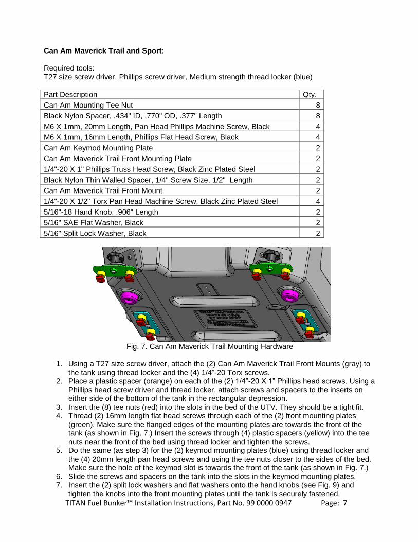
Can Am Maverick Trail and Sport:
Required tools: T27 size screw driver, Phillips screw driver, Medium strength thread locker (blue)
Part Description Qty.
Can Am Mounting Tee Nut 8
Black Nylon Spacer, .434" ID, .770" OD, .377" Length 8
M6 X 1mm, 20mm Length, Pan Head Phillips Machine Screw, Black 4
M6 X 1mm, 16mm Length, Phillips Flat Head Screw, Black 4
Can Am Keymod Mounting Plate 2
Can Am Maverick Trail Front Mounting Plate 2
1/4"-20 X 1" Phillips Truss Head Screw, Black Zinc Plated Steel 2
Black Nylon Thin Walled Spacer, 1/4" Screw Size, 1/2" Length 2
Can Am Maverick Trail Front Mount 2
1/4"-20 X 1/2" Torx Pan Head Machine Screw, Black Zinc Plated Steel 4
5/16"-18 Hand Knob, .906" Length 2
5/16" SAE Flat Washer, Black 2
5/16" Split Lock Washer, Black 2
Fig. 7. Can Am Maverick Trail Mounting Hardware
1. Using a T27 size screw driver, attach the (2) Can Am Maverick Trail Front Mounts (gray) tothe tank using thread locker and the (4) 1/4”-20 Torx screws.
2. Place a plastic spacer (orange) on each of the (2) 1/4”-20 X 1” Phillips head screws. Using aPhillips head screw driver and thread locker, attach screws and spacers to the inserts oneither side of the bottom of the tank in the rectangular depression.
3. Insert the (8) tee nuts (red) into the slots in the bed of the UTV. They should be a tight fit.4. Thread (2) 16mm length flat head screws through each of the (2) front mounting plates
(green). Make sure the flanged edges of the mounting plates are towards the front of thetank (as shown in Fig. 7.) Insert the screws through (4) plastic spacers (yellow) into the teenuts near the front of the bed using thread locker and tighten the screws.
5. Do the same (as step 3) for the (2) keymod mounting plates (blue) using thread locker andthe (4) 20mm length pan head screws and using the tee nuts closer to the sides of the bed.Make sure the hole of the keymod slot is towards the front of the tank (as shown in Fig. 7.)
6. Slide the screws and spacers on the tank into the slots in the keymod mounting plates.7. Insert the (2) split lock washers and flat washers onto the hand knobs (see Fig. 9) and
tighten the knobs into the front mounting plates until the tank is securely fastened.

TITAN Fuel Bunker™ Installation Instructions, Part No. 99 0000 0947 Page: 8
Arctic Cat Wildcat 1000 (‘13-‘16), Arctic Cat Sport and Trail (‘15-current):
Required tools: T27 size screw driver, Phillips screw driver, Medium strength thread locker (blue), (M6 x .75 size bolts and/or washers)*
Part Description Qty.
Arctic Cat 1000 Front Mounting Plate 1
Arctic Cat 1000 Rear Mounting Plate 1
1/4"-20 X 1" Phillips Truss Head Screw, Black Zinc Plated Steel 1
Black Nylon Thin Walled Spacer, 1/4" Screw Size, 1/2" Length 1
Arctic Cat Wildcat 1000 Side Mount 2
1/4"-20 X 1/2" Torx Pan Head Machine Screw 4
5/16"-18 Hand Knob, .906" Length 2
5/16" SAE Flat Washer, Black Zinc Plated Steel 2
5/16" Split Lock Washer, Black Zinc-Plated Steel 2
Fig. 8. Arctic Cat Wildcat 1000 Mounting Hardware
1. Remove the plastic covers in the bed to access the bolt locations. Attach the Arctic Cat 1000Front Mounting Plate and the Arctic Cat 1000 Rear Mounting Plate to the bed of the UTVusing bolts provided with the UTV.*Note: depending on the model year, longer bolts and/or washers may be necessary.
2. Using a T27 size screw driver, attach the (2) Arctic Cat Wildcat 1000 Side Mounts to eachside of the rear of the tank using the (4) ¼”-20 x ½” Torx screws and thread locker.
3. Place the plastic spacer (orange) on the 1/4”-20 X 1” Phillips headscrew. Using a Phillips head screw driver and thread locker, attachscrew and spacer to the silver insert on the center line closest to thefront of the tank.
4. Set tank into the bed on the mounting plates, allowing the screw andspacer to slip through the hole in the front mounting plate. Slide thetank backwards into place until the holes in the side mounts align withthe holes in the rear mount.
5. Add the split lock washers and flat washers to the hand knobs (asshown in Fig. 9) and tighten the knobs until the tank is securelyfastened. Fig. 9. Knob with washers

TITAN Fuel Bunker™ Installation Instructions, Part No. 99 0000 0947 Page: 9
Universal Mounting Kit (Drilling Required)
Required tools: T27 size screw driver, Medium strength thread locker (blue), (4) Bolts, (4) Nuts, (8) Washers, Power drill with drill bit, Socket for drill OR torque wrench, Crescent Wrench
Part Description Qty.
RZR Front Lock N Ride Mount 2
1/4"-20 X 1/2" Torx Pan Head Machine Screw, Black Zinc Plated Steel 8
RZR 570 Rear Passenger Mount 1
RZR 570 Rear Driver Mount 1
Drilling Template 1
1. Using the included mounting template, mark the hole centers on the mounting surfaceBefore drilling, check under the bottom of the bed to make sure there are no crossmembers on the bed that will interfere with installation. If there is a conflict, move the“footprint” of the tank slightly to clear the obstruction.
2. Drill holes in the bed of your vehicle large enough to accommodate for the size of bolts youhave chosen. The slots in the mounts are 3/16” wide. If you prefer to use a larger bolt size,you will also need to enlarge the size of the holes in the mounts. Mark the hole locations oneach mount and drill the slot out larger to accommodate for larger bolts.
3. Using a T27 size screw driver, attach the RZR Rear Passenger Side and Driver Side Mountsusing thread locker and (2) ¼”-20 X ½” Torx screws each. Note that these brackets looksimilar, but are mirror images of each other. Orient the mounts so the hole is as far to theback of the tank as possible.
4. Using a T27 size screw driver, attach the (2) RZR Front Lock N Ride Mounts using threadlocker and the (4) ¼”-20 X ½” Torx screws.
5. Position the tank in the bed and thread the bolts through the mounts and bed. Washers arerecommended to distribute the weight and prevent the bolts from pulling through the bed ofthe vehicle.
6. Using a crescent wrench to secure the nut, tighten the bolts and nuts to 25 lb-ft using eithera power drill or a torque wrench.

TITAN Fuel Bunker™ Installation Instructions, Part No. 99 0000 0947 Page: 10
II. Wire Grounding Stud and Electric Pump to UTV
Step Description
3 Inside the tank is a large plastic bag with wiring pieces. From the smaller bag, pull the 14 gauge black wire with attached ring terminal and the small screw. Using a Phillips screw driver, attach the ring terminal to the grounding stud head at the back of the tank. (See Fig. 10.)
4 Measure out the 14 gauge black wire to a location on the frame to ground the tank. Make sure the wire will be grounded to metal frame and not plastic bed cover. Cut the wire and strip it back to attach the provided ring terminal. Crimp the ring terminal in place, and then use a small propane torch or cigarette lighter to melt the heat shrink plastic.
5 Screw the newly attached ring terminal into the metal frame of the UTV, making sure it has a good connection with the metal and that the wire has some slack. (See Fig. 11.)
Note: The Fuel Bunker is designed to be removable. A butt splice terminal has been provided that will allow the Fuel Bunker to be removed from the UTV without having to unscrew one end of the grounding wire. (See Fig. 12.)
6 If desired, cut the grounding wire towards the middle and strip both ends. Attach, crimp, and heat shrink the ends of the butt splice terminal to the cut ends of the grounding wire.
NOTE: Never under ANY circumstances operate the TITAN Fuel Bunker without the grounding wire attached. Injury or death may occur.
Fig. 10 Fig. 11

TITAN Fuel Bunker™ Installation Instructions, Part No. 99 0000 0947 Page: 11
Fig. 12. Completed Grounding Wire Assembly Fig. 13. Power wires connected to battery.
Step Description
7 From the larger plastic bag, remove the 10 foot lengths of red and black wire with attached ring terminals. Attach each ring terminal to the battery of the UTV, as shown in Fig. 13. Do NOT attempt this while vehicle is running.
8 Run the wires toward the bed of the UTV along a desired path, avoiding exposed regions and heat sources. Run the wires until they reach a convenient location near the TITAN Fuel Bunker.
Note: The lid of the TITAN Fuel Bunker should remain closed at all times it is not in use to prevent fuel spills in case of accident or rollover. For this reason, the power wires for the pump need to be cut and attached with Male/Female flat connectors (see following instructions.) One set of connectors will be stored inside the tank with the pump while the other will be secured to the frame of the UTV at a convenient location outside the tank to allow the lid to completely close when pump is not in use.
9 Remove from the large plastic bag the two loose heat-shrink splice terminals along with the Male/Female flat connector that does NOT have splice terminals already connected. Cut the power wires at the location you wish your pump to access power and strip the ends of all 4 wires. Connect and crimp the red power wire to the red wire of the flat connector. Connect and crimp the black ground power wire to the black wire of the flat connector. Use a small propane torch or cigarette lighter to melt the heat-shrink plastic. See Fig. 14 for wiring diagram.
10 To avoid weather damage or other issues, wrap the exposed power wires in the provided wire loom (from the small plastic bag) and secure it with black electrical tape. Zip-tie the wires and loom along its length to convenient and stable location on the UTV. (See Figs. 15 and 16.)

TITAN Fuel Bunker™ Installation Instructions, Part No. 99 0000 0947 Page: 12
Fig. 14. Wiring diagram for pump wires
Fig. 15. Protect exposed wire with wire loom. Fig. 16. Completed power connection
11 Withdraw the pump wires from the TITAN Fuel Bunker. Measure the wires out to the flat connector for the power wires and cut the wires. (Note: Make sure to leave some slack in the wires.) Strip the ends of both wires to connect it to the flat connector. Connect the red pump wire to the red flat connector wire and the black pump wire to the black connector wire. Crimp the pump wires into the splice terminals and melt the heat shrink plastic. (See Figs. 14 and 17.)

TITAN Fuel Bunker™ Installation Instructions, Part No. 99 0000 0947 Page: 13
Fig. 18. Vent Cap
Fig. 17. Completed pump and power wiring
III. Fill and Final CheckStep Description
12 Make a complete careful check of all components to be sure that all bolts, clamps, caps, accessories, and misc. are tight and secure.
13 Locate the vent on the fuel cap (see Fig. 18.) This vent cap is a specialty product, designed to use with gas fuel tanks. This seal will cause pressure or vacuum to build up in the tank unless the tank is frequently vented. To unlock the vent, push the red button down and twist counter-clockwise. Hold the button down to vent the tank. To lock the vent closed, push the button down and twist clockwise. Do NOT tamper with the vent or force the cap to stay in the open vent position for any extended periods of time.
NOTE: Frequently vent the fuel tank to prevent pressure or vacuum build-
up in the tank. ALWAYS vent the fuel tank before opening the cap
and both before and after pumping fuel.
14 Ensure the pump works before taking the UTV out with the TITAN Fuel Bunker installed. Check to make sure the ground wire is connected and has not come loose. Open the lid of the tank and withdraw the pump wires. Connect the pump to the power wires. Turn the pump on and off using the gray switch on top of the pump (see Fig. 19) to ensure there is no disconnect or short in the wiring.

TITAN Fuel Bunker™ Installation Instructions, Part No. 99 0000 0947 Page: 14
15 In the hose line is a ball valve used as an extra leak protection in case of pump failure (see Fig. 20.) Always open the ball valve (knob lined up with the hose) before switching on the pump. Always close the ball valve (knob twisted to the side) when pump is not in use.
16 IMPORTANT: Fill tank completely with fuel and inspect all components carefully to be sure that there are no leaks or other problems. Check the operation of any valves, pumps or control systems.
Fig. 19. Pump power switch
Fig. 20. In-line Ball Valve

TITAN Fuel Bunker™ Installation Instructions, Part No. 99 0000 0947 Page: 15
IV. Important Operating Instructions
1) Be careful not to restrict air flow around and under the TITAN Fuel Bunker™. 2) Be sure the Fuel Bunker is securely fastened in the vehicle. 3) Be sure the ground wire is properly attached before filling or using. 4) When not in use, be sure the in-line safety ball valve is closed. 5) Do not fuel a vehicle when the engine is running or hot. 6) When operating the vehicle, be sure the fuel cap vent is “closed”. 7) Always vent the fuel cap to relieve any pressure or vacuum before removing cap. 8) Open the vent on the fuel cap frequently to relieve any pressure or vacuum build up
which might occur. Higher temperatures and elevation changes require more frequent venting.
9) Do not overfill the Fuel Bunker. 10) Place the fuel nozzle in the vehicle fill neck before opening the ball valve and
switching “on” the pump. 11) KEEP ANY OPEN FLAME OR HEAT SOURCE AWAY WHEN FILLING OR
OPERATING THE FUEL BUNKER. 12) Make sure the dispensing hose is drained and the safety ball valve closed before
storing.
IMPORTANT: Never load more than 20 lbs. (9.07 kg) on top of the Fuel Bunker. Never load more than 15 lbs. (6.8 kg) in the storage compartment inside the Fuel Bunker. Be careful to never exceed the total rated load of your vehicle’s bed.

TITAN Fuel Bunker™ Installation Instructions, Part No. 99 0000 0947 Page: 16
Be sure to return the completed warranty registration for your new Titan product; or you can register on-line at www.titanfueltanks.com.
You will find your tank’s serial number on the bottom of the tank.
Write your tank’s Serial Number here:
Product must be registered within sixty (60) days of receipt for the warranty to be valid. Other conditions may apply. Consult TITAN’s full warranty for details.
*All capacities are approximate.
Warranty is void if product is improperly installed.
For questions or customer service call (800) 728-4982
TITAN™ Fuel Tanks
P.O. Box 2225 Idaho Falls, ID 83403 USA
Telephone (208) 522-1325, FAX (208) 529-2162 Toll Free: (800) 728-4982
www.titanfueltanks.com
TITAN Fuel Tanks™ are PROUDLY MADE IN THE USA ©2020 Supertanks, LLC. All rights reserved.
Rev. 01.30.20