
Tightening of High-Strength Metric Bolts€¦ · TIGHTENING OF HIGH-STRENGTH METRIC BOLTS 7....
76
1. Report No. 2. Government Accession No. TX-97 /2958-1 F 4. Title and Subtitle TIGHTENING OF HIGH-STRENGTH METRIC BOLTS 7. Author(s) Michael J Gilroy and Karl H. Frank 9. Performing Organization Name and Address Center for Transportation Research The University of Texas at Austin 3208 Red River, Suite 200 Austin, Texas 78705-2650 12. Sponsoring Agency Name and Address Texas Department of Transportation Research and Technology Transfer Office P. 0. Box 5080 Austin, Texas 78763-5080 15. Supplementary Notes Technical Report Documentation Page 3. Recipient's Catolog No. 5. Report Dote June 1997 6. Performing Organization Code 8. Performing Org. Report No. Research Report 2958-1 F 10. Work Unit No. {TRAIS) 11. Contract or Grant No. Research Study 7-2958 13. Type of Report and Period Covered Final 14. Sponsoring Agency Code Project conducted in cooperation with the Texas Department of Transportation. Research project title: "Tightening of High-Strength Bolts" 16. Abstract The initially mandated and non-optional use of metric dimensions and designs for new highway construction requires the use of metric dimension fasteners. Even though the ASTM Specifications A325M and A490M for metric high strength bolts have been available for almost 20 years, they have not been used in any U.S. construction and have only been manufactured in a test lot by one U.S. manufacturer. This research examines the influence of bolt length, grip length, bolt strength, and thread lubrication on the relationship between nut rotation and bolt tension. Two different diameters of A325M metric bolts were tested: 24-mm bolts with lengths of 70, 100, and 120 mm, and 20-mm bolts with lengths of 50, 60, and 70 mm. The performance results for the two sizes of fastener are evaluated and compared with the present nut rotation requirements for inch fasteners. The results are used to set installation requirements for the turn-of-the-nut procedure and changes to the rotational capacity test to accommodate metric fasteners. 17. Key Words Metric bolts, bolt performance 19. Securily Classif. (of this report) Unclassified Form DOT F 1700.7 (8-72) 18. Distribution Statement No restrictions. This document is available to the public through the National Technical Information Service, Springfield, Virginia 22161. 20. Securily Classif. (of this page) Unclassified Reproduction of completed page authorized 21 . No. of Pages 78 22. Price
Transcript of Tightening of High-Strength Metric Bolts€¦ · TIGHTENING OF HIGH-STRENGTH METRIC BOLTS 7....

1 . Report No. 2. Government Accession No.
TX-97 /2958-1 F
4. Title and Subtitle
TIGHTENING OF HIGH-STRENGTH METRIC BOLTS
7. Author(s)
Michael J Gilroy and Karl H. Frank
9. Performing Organization Name and Address
Center for Transportation Research The University of Texas at Austin 3208 Red River, Suite 200 Austin, Texas 78705-2650
12. Sponsoring Agency Name and Address
Texas Department of Transportation Research and Technology Transfer Office P. 0. Box 5080 Austin, Texas 78763-5080
15. Supplementary Notes
Technical Report Documentation Page
3. Recipient's Catolog No.
5. Report Dote June 1997
6. Performing Organization Code
8. Performing Org. Report No.
Research Report 2958-1 F
1 0. Work Unit No. {TRAIS)
11. Contract or Grant No.
Research Study 7-2958
13. Type of Report and Period Covered
Final
14. Sponsoring Agency Code
Project conducted in cooperation with the Texas Department of Transportation. Research project title: "Tightening of High-Strength Bolts"
16. Abstract
The initially mandated and non-optional use of metric dimensions and designs for new highway construction requires the use of metric dimension fasteners. Even though the ASTM Specifications A325M and A490M for metric high strength bolts have been available for almost 20 years, they have not been used in any U.S. construction and have only been manufactured in a test lot by one U.S. manufacturer.
This research examines the influence of bolt length, grip length, bolt strength, and thread lubrication on the relationship between nut rotation and bolt tension. Two different diameters of A325M metric bolts were tested: 24-mm bolts with lengths of 70, 100, and 120 mm, and 20-mm bolts with lengths of 50, 60, and 70 mm. The performance results for the two sizes of fastener are evaluated and compared with the present nut rotation requirements for inch fasteners. The results are used to set installation requirements for the turn-of-the-nut procedure and changes to the rotational capacity test to accommodate metric fasteners.
17. Key Words
Metric bolts, bolt performance
19. Securily Classif. (of this report)
Unclassified
Form DOT F 1700.7 (8-72)
18. Distribution Statement
No restrictions. This document is available to the public through the National Technical Information Service, Springfield, Virginia 22161.
20. Securily Classif. (of this page)
Unclassified
Reproduction of completed page authorized
21 . No. of Pages
78
22. Price


TIGHTENING OF HIGH STRENGTH METRIC BOLTS
BY
MICHAEL J. GILROY AND KARL H. FRANK
Research Report No. 7-2958-lF
Research Project 7-2958
"Tightening of High-Strength Bolts
conducted for the
Texas Department of Transportation
IN COOPERATION WITH THE
U.S. Department of Transportation
Federal Highway Administration
by the
CENTER FOR TRANSPORTATION RESEARCH
BUREAU OF ENGINEERING RESEARCH
THE UNIVERSITY OF TEXAS AT AUSTIN
June 1997


IMPLEMENTATION
The research has shown that the following changes need to be made to the AASHTO and TxDOT Specifications for Metric Fasteners to accommodate the difference between metric and inch fasteners.
1. The specified tum-of-the-nut requirement for bolts with length to diameter ratios less than or equal to four should be changed from 1/3 tum to 1/2 tum.
2. The negative 30° tolerance for turns should be eliminated for all lengths to diameter ratios.
3. The assumed maximum fastener tension in a short bolt rotational capacity test should be calculated as 1.15*0.7*average bolt tensile strength from the mill report of the bolts.
This third change listed above should also be considered for inch bolts since it is based upon the maximum tension recorded during tightening of the bolts relative to the mill test values. The maximum tension relative to the mill test results should be similar for inch bolts.
NOT INlENDED FOR CONSTRUCTION,
BIDDING, OR PERMIT PURPOSES
Karl H. Frank, Texas P.E. #48953
Research Supervisor
The contents of this report reflect the views of the authors, who are responsible for the facts and accuracy of the data presented herein. The contents do not necessarily reflect the views of the Texas Department of Transportation. This report does not constitute a standard, specification, or regulation.
iii


TABLE OF CONTENTS
CHAPTER 1 INTRODUCTION .............................................................................................................................. 1 1.1 Introduction ................................................................................................................................................. I 1.2 Project Scope ............................................................................................................................................... 1 1.3 Project Objective .......................................................................................................................................... 1 1.4 Project Organization .................................................................................................................................... 2
CHAPTER 2- THEORETICAL BACKGROUND .................................................................................................... 3 2.1 Introduction .................................................................................................................................................. 3 2.2 Turn-of-the-Nut Tightening ......................................................................................................................... 3 2.3 Factors Affecting Bolt Performance ............................................................................................................ 4
2.3.1 Grip Length ........................................................................................................................................... 4 2.3.2 Lubrication and Installation Torque ...................................................................................................... 5 2.3.3 Stiffness of Test Setup .......................................................................................................................... 6
2.4 Rotational Capacity Test .............................................................................................................................. 7 2.4.1 Long Bolt Tests ..................................................................................................................................... ? 2.4.2 Short Bolt Tests .................................................................................................................................... 7
2.5 Differences Between A325M and A325 Bolts ............................................................................................ 7 2.5.1 Thread Pitch .......................................................................................................................................... ? 2.5.2 Reduction in Required Strength for Larger Bolts ................................................................................. 8 2.5.3 Hole Size ............................................................................................................................................... 8
CHAPTER 3- TEST PROGRAM .............................................................................................................................. 9 3 .1 Introduction ................................................................................................................................................. 9 3.2 Fastener Properties ....................................................................................................................................... 9
3.2.1 Dimensions ........................................................................................................................................... 9 3.2.2 Chemistry Composition ........................................................................................................................ 9 3.2.3 Hardness Tests ...................................................................................................................................... 9 3.2.4 Direct Tension Tests ........................................................................................................................... 14
3.3 Torque-Tension-Tum Tests ....................................................................................................................... 16 3.3.1 Bolt Matrix .......................................................................................................................................... 16 3.3 .2 Load Cell Solid Plate System ........................................................................................................... 16 3.3.3 Load Cell Box System ........................................................................................................................ 19 3.3.4 Short Grip Skidmore Test Setup ......................................................................................................... 22 3.3.5 Test Procedure .................................................................................................................................... 22
3.4 TxDOT Tests ............................................................................................................................................. 22 3.5 Solid Plate Tests ......................................................................................................................................... 23
3.5.1 Bolt Test Matrix .................................................................................................................................. 23 3.5.2 Determining Tension-Elongation Relationship .................................................................................. 23 3.5.3 Determining Elongation-Rotation Relationship .................................................................................. 23
CHAPTER 4- DATA PRESENTATION ................................................................................................................. 27 4.1 Introduction ............................................................................................................................................... 27 4.2 Snug Condition .......................................................................................................................................... 27 4.3 Effect of Weathering upon Lubrication Performance ................................................................................ 30
v

4.4 Bolt Perfonnance in Different Test Setups ............................................................................................... .30 4.5 Rotational Stiffuess .................................................................................................................................... 35 4.6 Nut Rotation ............................................................................................................................................... 35 4.7 Ultimate Nut Rotational Capacity .............................................................................................................. 38 4.8 Rotational Capacity Test Requirements ..................................................................................................... 43
4.8.1 Nut Factor I Maximum Torque .......................................................................................................... .43 4.8.2 Ductility .............................................................................................................................................. 46 4.8.3 Rotation Verification Test. .................................................................................................................. 47
CHAPTER 5 -RECOMMENDED SPECIFICATION CHANGES ........................................................................ .49 5.1 Introduction ............................................................................................................................................... 49 5.2 Turn-of-the-Nut Requirements .................................................................................................................. 49 5.3 Rotational Capacity Test ............................................................................................................................ Sl
5.3.1 Nut Factor I Maximum Torque ........................................................................................................... 51 5.3.2 Ductility .............................................................................................................................................. 51
5.4 Rotation Verification Test ........ , ................................................................................................................ 52
CHAPTER 6 SUMMARY OF CONCLUSIONS AND RECOMMENDED CHANGES TO THE AASHTO SPECIFICATION ......................................... , ............................................................................................. 53
6.1 Conclusions ................................................................................................................................................ 53 6.2 Recommended Changes to the AASHTO Bolt Specification .................................................................... 54
APPENDIX A- TEST DATA ................................................................................................. , ................................ 55
vi

LIST OF FIGURES
Figure 2. I Sample tension-turn relationship for A325 bolt. ......................................................................................... .3 Figure 2. 2 Effect of grip length on bolt behavior ......................................................................................................... .5 Figure 2. 3 Effect of poor lubrication I high installation torque on bolt behavior .......................................................... 6 Figure 2. 4 Comparison of thread pitches for A325 and A325M bolts .......................................................................... 8 Figure 3. I Rc hardness test values for M24 and M20 A325M bolts ........................................................................... 13 Figure 3. 2 Skidmore-Wilhelm bolt calibrator used for direct tension tests ................................................................. 15 Figure 3. 3 Example of flush grip for a 24 mm x 70 mm bolt. ..................................................................................... l7 Figure 3. 4 Example of three turns grip for a 24 mm x 70 mm bolt... .......................................................................... l7 Figure 3. 5 Side view of load cell- flat plate system ................................................................................................... 18 Figure 3. 6 Front view of load cell - flat plate system .................................................................................................. 18 Figure 3. 7 Rear view of load cell flat plate system ................................................................................................... 19 Figure 3. 8 Load cell box system ................................................................................................................................. 20 Figure 3. 9 Grip length adjustment apparatus for load cell box system ....................................................................... 20 Figure 3. 10 Top view of bolt head mounting insert .................................................................................................... 21 Figure 3. 11 Side view of bolt head mounting insert .................................................................................................... 21 Figure 3. 12 Short grip Skidmore test setup ................................................................................................................. 22 Figure 3. 13 C Frame dial gauge .................................................................................................................................. 24 Figure 3. 14 Solid plate test setup ................................................................................................................................ 24 Figure 4. 1 Torque required to reach 10% of minimum specified tensile strength ....................................................... 28 Figure 4. 2 Torque required to reach 44.48 kN tension in fastener .............................................................................. 28 Figure 4. 3 Initial tension-turn curve for a 20 x 70 flush grip bolt up to minimum specified fastener tension in
load cell box ......................................................................................................................................................... 29 Figure 4. 4 Initial tension-turn curve for a 20 x 70 flush grip bolt up to minimum specified fastener tension in
a solid plate .......................................................................................................................................................... 30 Figure 4. 5 Relative performance of24 x 70 flush grip bolts in different test setups .................................................. .32 Figure 4. 6 Relative performance of 24 x 120 three turn grip bolts in different test setups ......................................... 32 Figure 4. 7 Relative performance of 24 x 120 flush grip bolts in different test setups ................................................. 33 Figure 4. 8 Relative performance of 20 x 50 flush grip bolts in different test setups ................................................... 33 Figure 4. 9 Relative performance of 20 x 70 flush grip bolts in different test setups ................................................... 34 Figure 4. I 0 Example of rotational stiffness calculation for 20 x 70 flush grip bolt in load cell box test setup .......... .34 Figure 4. 11 Comparison of rotational stiffnesses for 24 mm bolts in torque-tension-turn and solid plate tests .......... 36 Figure 4. 12 Comparison of rotational stiffnesses for 24 mm bolts in load cell solid plate and load cell box
tests ...................................................................................................................................................................... 36 Figure 4. 13 Comparison of rotational stiffnesses for 20 mm bolts in torque-tension-turn and solid plate tests .......... 37 Figure 4. 14 Comparison of rotational stiffnesses for 20 mm bolts in torque-tension-turn tests ................................. .37 Figure 4. 15 Repaired nut rotations to reach minimum specified fastener tension for 24 x 70 flush grip bolts .......... .38 Figure 4. 16 Required nut rotations to reach minimum specified fastener tension for 24 x 100 three tum grip
bolts ...................................................................................................................................................................... 39 Figure 4. 17 Required nut rotations to reach minimum specified fastener tension for 24 x 100 flush grip bolts ......... 39 Figure 4. 18 Required nut rotations to reach minimum specified fastener tension for 24 x 120 three turn grip
bolts ...................................................................................................................................................................... 40 Figure 4. 19 Required nut rotations to reach minimum specified fastener tension for 24 x 120 flush grip bolts ........ .40 Figure 4. 20 Required nut rotations to reach minimum specified fastener tension for 20 x 50 flush grip bolts ......... ..41 Figure 4. 21 Required nut rotations to reach minimum specified fastener tension for 20 x 60 flush grip bolts ......... ..41 Figure 4. 22 Required nut rotations to reach minimum specified fastener tension for 20 x 70 flush grip bolts .......... .42 Figure 4. 23 Ultimate rotational capacity of bolts in solid plate tests ......................................................................... .42 Figure 4. 24 Torque vs. tension for 24 x 120 flush grip bolt. ....................................................................................... 43
vii

Figure 4. 25 Average nut factors in torque-tension-turn tests ...................................................................................... 44 Figure 4. 26 Maximum torque in test/AASHTO maximum allowable torque .............................................................. 44 Figure 4. 27 Maximum tension in Test/(0.7*bolt tension strength) for torque-tension-turn tests ............................... .45 Figure 4. 28 Maximum tension in Test/(0.7*bolt tensile strength) for TxDOT tests .................................................. .45 Figure 4. 29 Tension at one turn I minimum specified fastener tension for TxDOT tests ........................................... .46 Figure 4. 30 Turns to failure for all bolts in TxDOT tests .......................................................................................... .47 Figure 4. 31 Required nut rotations to reach 1.05*0.70*minimum specified tensile strength in TxDOT tests ........... .48 Figure 5. 1 General tension-turn behavior ................................................................................................................... .49 Figure 5. 2 Comparison of turns required to reach 0.7 x min.·spec. tensile strength with turns required to reach
0.7 x actual bolt tensile strength ........................................................................................................................... 50 Figure 5. 3 Comparison of turns to minimum specified fastener tension with current AASHTO turn-of-the-nut
requirements ......................................................................................................................................................... 50
viii

LIST OF TABLES
Table 2. 1 AASHTO Required Nut Rotation from Snug Condition to Reach 70 Percent of Minimum Tensile Strength of Boltsa.b ................................................................................................................................................ .4
Table 3. 1 Measured Dimensions of Bolts (mm) ......................................................................................................... 10 Table 3. 2 Measured Dimensions of Nuts (mm) .......................................................................................................... 1 0 Table 3. 3 ANSI Bolt Dimension Requirements (mm) ................................................................................................ 11 Table 3. 4 ANSI Nut Dimension Requirements (mm) ................................................................................................. 11 Table 3. 5 Chemistry Composition of 24 mm Bolts .................................................................................................... .ll Table 3. 6 Chemistry Composition of20 mm Bolts ..................................................................................................... 12 Table 3. 7 Chemistry Composition of 6H GRIOS Nuts ............................................................................................... 12 Table 3. 8 ASTM Chemical Requirements for Bolts and Nuts .................................................................................... 12 Table 3. 9 Average Rc Hardness Test Results for M24 and M20 A325M Bolts and Nuts .......................................... .l4 Table 3. 10 Ultimate Tensile Strength (Fu) ofBolts .................................................................................................... 15 Table 3. 11 Torque-Tension-Turns Bolt Test Matrix ................................................................................................... 16 Table 3. 12 Solid Plate Test Bolt Matrix ..................................................................................................................... 23 Table 3. 13 Summary of Bolt Tests ............................................................................................................................. 25 Table 4. 1 Average Turns to Failure for Torque-Tension-Turn Tests .......................................................................... 31 Table 4. 2 Average Nut Factors for Torque-Tension-Tum Tests ................................................................................ .31
ix

X

SUMMARY
The mandated use of metric dimensions and designs for new highway construction requires the use of metric dimension fasteners. Even though the ASTM Specifications A325M and A490M for metric high strength bolts have been available for almost 20 years, they have not been used in any U.S. construction and have only been manufactured in a test lot by one U.S. manufacturer.
This research examines the influence of bolt length, grip length, bolt strength, and thread lubrication on the relationship between nut rotation and bolt tension. Two different diameters of A325M metric bolts were tested: 24 mrn bolts with lengths of 70, 100, and 120 mrn, and 20 mrn bolts with lengths of 50, 60, and 70 mrn. The performance results for the two sizes of fastener are evaluated and compared with the present nut rotation requirements for inch fasteners. The results are used to set installation requirements for the tum-of-the-nut procedure and make all required changes to the rotational capacity test to accommodate metric fasteners.
xi


CHAPTER I
INTRODUCTION
1.1 INTRODUCTION
The mandated use of metric dimensions and designs for new highway construction requires the use of metric dimension fasteners. The ASTM Specifications A325M and A490M for metric high strength bolts, which were first published in 1979, have never been utilized. The specifications were developed in response to early metrification programs. These specifications differ from the European and Japanese specifications for similar bolts. The thread form, nut height, and nut strength are different from foreign specifications. The ASTM specifications were developed to provide a fastener which would behave similar to the present inch series bolts. Even though these specifications have been available for almost 20 years, they have not been used in any U. S. construction and have only recently been manufactured in a test lot by one U.S. manufacturer.
The Texas Department of Transportation (TxDOT) requires the use of the tum-of-the-nut installation method, and requires the manufacturer and installer to perform a rotational capacity test of the fastener assembly. The tum-of-the-nut installation method presently used was developed for inch fasteners and has never been examined using fasteners manufactured to metric specifications. A limited number of tests have been reported by two bolt manufacturers comparing cap screw metric bolts with equivalent inch series bolts. The results indicate that the metric fasteners do not provide the same tension for a given rotation as the inch bolts. Research to determine the correct method of installing metric fasteners by the tum-of-the-nut method is needed. In addition, any modifications to the rotational capacity test to accommodate the different behavior of the metric fasteners must be determined prior to requiring this test.
1.2 PROJECT SCOPE
The research examines the influence of bolt length, grip length, bolt strength, and thread lubrication on the relationship between nut rotation and bolt tension. Two different diameters of A325M metric bolts were tested: 24 mm bolts with lengths of70, 100, and 120 mm, and 20 mm bolts with lengths of 50, 60, and 70 mm. The performance results for the two sizes of fastener are evaluated and compared with the present nut rotation requirements for the inch fasteners. The results are used to set installation requirements for the turn-of-the-nut procedure and make any required change to the rotational capacity test to accommodate metric fasteners.
1.3 PROJECT OBJECTIVE
The overall goal of the A325M bolt research project is determine the correct method of installing and testing metric fasteners. The results and concJusions presented in this report are intended to increase the reliability of bolted connections and to provide necessary data relevant to the behavior of metric fasteners as the bridge industry makes the transition to the metric system.
1

1.4 PROJECT ORGANIZATION
The experimental efforts portion of the research was a cooperative effort between the sponsor, Texas Department of Transportation, and The University of Texas at Austin. The experimental work conducted at TxDOT was performed by Michael E. Smith of the Materials and Tests Division. Ronnie Medlock, also of the Materials and Tests Division, supervised the experimental work performed by TxDOT and was also the project director of the research.
TxDOT performed rotational capacity tests in their laboratory and had the chemistry tests performed on the fasteners. The remainder of the work was performed by The University of Texas. The replicate testing by TxDOT simulated the field tests normally performed at the job-site.
2

CHAPTER2
THEORETICAL BACKGROUND
2.1 lNTRODUCTION
The turn-of-the-nut installation method specifies a nut rotation range to produce a bolt tension which exceeds the minimum required fastener tension for slip critical and direct tension connections. This procedure is based on thorough research on the performance characteristics of A325 and A490 inch bolts. To date, only one manufacturer has attempted to make a fastener to the ASTM A325M metric specifications. As a result, there has been minimal research on the behavior of metric structural steel fasteners. The differences between the A325M and A325 bolts, however, are enough to warrant research to determine the applicability of the turn-of-the-nut method and the rotational capacity test to metric bolts.
2.2 TuRN-OF-THE-NUT TIGHTENING
The tightening behavior of a bolt-nut-washer assembly can be characterized by plotting the tension induced by the tightening process against the number of turns of the nut. Nut turns are measured from a snug tight condition, defined by the AASHTO Specification [13] as "the tightness that exists when the plies of the joint are firm in contact. This may be attained by a few impacts of an impact wrench or the
Bolt Tension
Specified Nut Rotation
full effort of a man using an ordinary spud wrench".
Figure 2.1 shows the idealized behavior of a fastener installed using the turn-of-the-nut procedure. The fastener has a long inelastic plateau in which the installed fastener tension is not appreciably affected by the nut rotation. Failure occurs by either bolt fracture or stripping of the bolt or nut. The nut rotations within the tolerances specified in the ASTM Specification are designed to produce an installation tension that exceeds the required minimum.
Figure 2. 1 Sample tension-tum relationship for A325 bolt For slip-critical connections and connections subjected to direct
tension, the minimum required fastener tension is equal to 70 percent of the specified minimum tensile strength of the bolt. The specified nut rotation values to reach the required fastener tension were
3

determined in previous research on A325 and A490 inch bolts. These nut rotation requirements are presented in Table 2.1.
2.3 FACTORS AFFECTING BOLT PERFORMANCE
The shape of the tension-tum curve depends on a variety of factors such as the bolt strength, grip length, lubrication, and stiffness of bolted material or test setup. Each of these variables can significantly alter the relative performance of the fastener.
2.3.1 Grip Length
The grip length is the total thickness of material between the head of the bolt and the washer face of the nut, exclusive of washers. Figure 2.2 shows the relative behavior of bolts with the same mechanical properties and lubrication but with larger and smaller grip lengths. These tension-tum curves are graphed along with the ideal behavior for the tum-of-the-nut procedure. The initial slope, R, of the curves is essentially linear elastic. In the elastic range, the relationship between the nut rotation, N, and the tension induced in the bolt, T, is defined by the relationship,
N = (T x L)/(Ae x Ex P) (2.1)
where L is the grip length, Ae is the effective bolt area, E is Young's Modulus, and P is the thread pitch. Therefore, the number of turns required to reach a specific fastener tension is directly proportional to the grip length. A bolt with a long grip length requires more turns to reach the required tension than a shorter bolt with the same diameter.
Table 2. 1 AASHTO Required Nut Rotation from Snug Condition to Reach 70 Percent of Minimum Tensile Strength of Boltsa.b
Bolt Length Disposition of Outer Face of Bolted Parts
(underside of head to end Both Faces normal to One face normal to bolt Both faces sloped not of bolt) bolt axis. axis and other sloped more than 1 :20 from
not more than 1 :20 normal to the bolt (beveled washer not axis (beveled washer
used) not used) Up to and including 4 l/3tum 1/2 tum 213tum diameters Over 4 diameters but not 1/2 tum 213tum 5/6 tum exceeding 8 diameters Over 8 diameters but not 213 tum 5/6tum 1 tum exceeding 12 diameters c
a. Nut rotatiOn 1s relat1ve to bolt regardless of the element (nut or bolt) bemg turned. For bolts installed by 1/2 tum and less, the tolerance should be plus or minus 30 degrees; for bolts installed by 213 tum and more, the tolerance should be plus or minus 45 degrees.
b. Applicable only to connections in which all material within the grip of the bolt is steel. c. For bolt lengths exceeding 12 diameters, the required rotation must be determined by actual tests in
a suitable tension measuring device which simulates the actual conditions.
4

Bolt Tension
Figure 2. 2
- ------- Ideal
------ Short Grip
- - - - - - Long Grip
Specified Nut Rotation
Effect of grip length on bolt behavior
The grip length is made up of the shank length and the threads in the grip. Because the shank is inherently stiffer than the threaded portion of the grip, the thread length within the grip affects the bolt behavior. As the thread length within the grip decreases, the maximum strength increases but the ductility decreases [5].
The turn-of-the-nut installation requirements based upon bolt length are designed to ensure that the bolt with the longer grip length will not have a tension less than the required at the lower bound value for required turns, and that the bolt with the shorter grip length does not fracture or have a tension less than required at the upper bound value for required turns as shown in Figure 2.2.
2.3.2 Lubrication and Installation Torgue
Tightening a bolted connection by turning the nut introduces torsion as well as tension into the bolt. The presence of torsional stress has a very significant effect on the tension-tum response of a fastener assembly. Research indicates that the torqued tension is typically 10 to 20% lower than the direct tension results [8 and 10]. The actual reduction in maximum tension is very sensitive to lubrication and thread conditions.
Three factors contribute to the resistance encountered in turning a nut. Energy or torque is required to force the nut up the inclined planes of the thread, to overcome the friction on the threads at the bolt nut interface, and to overcome the friction between the nut, washer, and the gripped material. Studies have shown that 90 percent of the energy will go into overcoming the friction. Therefore, lubrication on the nut face and threads is required to reduce the torque input. In one study with a lubricant called "NoOxide" on the nut threads and surface of A325 bolts, the torque was only 67% of that measured in the unlubricated state [7]. By lowering the torque, lubrication reduces the overall power requirements for installing high strength bolts and speeds up the tightening process.
Lubrication also has a significant effect on the tension-tum curve. Lack of lubrication significantly reduces the strength and ductility of bolts, as shown in Figure 2.3. In a study performed by Eaves at The
s

Bolt Tension
Lubricated
--- Weathered
University of Texas at Austin, A325 and · A490 fasteners cleaned of lubricant (weathered) were found to fail before the minimum specified bolt tension was reached. Installation torques were 60 percent higher for the clean threads in this case [8]. Torsion in a bolt increases as the bolt-nut thread friction increases. The combined state of stress reduces maximum tension and ductility.
The decrease in ductility should be taken into account when determining the effectiveness of the current nut rotation requirements. A short bolt at the maximum
Nut Rotation specification strength level with lesser lubrication, that is still acceptable based on
Figure 2. 3 Effect of poor lubrication 1 high instal- the nut factor requirement in the rotational lation torque on bolt behavior capacity test, should be used to determine the
upper bound value of required nut rotation. Similarly, a lower strength long bolt with lesser lubrication should be used to determine the minimum required installation turns.
The measured relationship between torque and tension in an A325 bolt-nut-washer assembly is reasonably linear up to near maximum load. The commonly used relationship,
Torque= Kx PxD (2.2)
relates the torque to the desired bolt tension, P, and the nominal diameter of the bolt, D. K is a dimensionless nut factor which depends on the material and the surface conditions of the threads, nut and washer. K was found to be between 0.18 and 0.29 for a wide variety of conditions in the field [6]. The Japan Industrial Standard [12] uses the same relationship between torque and tension, with the K factor ranging between 0.11 and 0.19 [9]. As a result of the wide variation in K values, the current RCSC specification requires that the actual torque-tension relationship (nut factor) must now be determined by an on-site calibration. In the rotational capacity test, the maximum allowable nut factor is 0.25.
2.3.3 Stiffness of Test Setup
Hydraulic bolt calibrators are typically used to conduct tension-tum calibration tests. These bolt calibrators have a lower stiffness than the solid plate connection configurations encountered in practice. During a test, the hydraulic bolt calibrators exhibit larger deformations than solid plate and solid plate load cell setups at the same tensile load.
In the tum-of-the-nut procedure, nut rotation is used to control strain and induce tension in the fastener. Nut rotation is used to calibrate bolt performance rather than bolt elongation. As a result, the nut rotation corresponding to a tension value in a hydraulic calibrator may be larger than the nut rotation to reach the same tension value in a solid plate setup. Various comparisons of Skidmore-Wilhelm bolt calibrator tension-tum curves to solid plate tension-tum curves for inch bolts are published. In the elastic range, the Skidmore may indicate 25 to 75 percent more turns to reach the minimum specified tension than are
6

required in a solid steel assembly [7]. Real connections typically have multiple ply "out of flat" plates. The total stiffness of these connections falls in between the stiffness of a hydraulic bolt calibrator and a solid plate. Therefore, a tension-turn test in a hydraulic bolt calibrator overestimates the required turns to the minimum specified tension value for a stiffer connection configuration. However, the results of solid plate tension-turn tests provide an upper bound stiffness for an actual multiple ply connection, and are necessary to ensure that the larger number of turns does not lead to bolt failure or a decrease in fastener tension below the required minimum.
2.4 ROTATIONAL CAPACITY TEST
The rotational capacity test is performed to check the performance of the bolt-nut-washer assemblies from each lot intended for installation.
2.4.1 Long Bolt Tests
A standard torque wrench is used to tighten the bolt assembly in a Skidmore-Wilhelm bolt tension calibrator or equivalent tension measuring device. The bolt is tightened to a snug tension equal to 10 percent of the specified minimum required installation tension. The nut is turned until the fastener tension exceeds the minimum required installation tension. At this point, an additional reading of tension and torque is recorded. The recorded torque value must not violate the following equation,
Torque < 0.25 x P x D
where P is the fastener tension and D is the nominal bolt diameter.
(2.3)
The nut is then turned to a rotation equal to 2 times the minimum required nut rotation. The minimum tension induced in the bolt at this rotation must be equal to or greater than 1.15 times the minimum required installation tension.
After the nut has been turned to the required rotation, the bolt assembly must show no signs of failure. Failure is defined as inability to achieve the required rotation, inability to remove the nut following the test, shear failure of the threads, or torsional failure of the bolt.
2.4.2 Short Bolt Tests
Bolts with lengths too short to be tested in the hydraulic bolt calibrator are tested in a steel joint. The test is essentially the same as with the bolt tension calibrator, except that the minimum turn test tension cannot be measured and does not apply. However, the torque at any point in the test cannot violate the previous limiting equation (2.3) with an assumed tension taken as 1.15 times the minimum required tension.
2.5 DIFFERENCES BETWEEN A325M AND A325 BOLTS
2.5.1 Thread Pitch
The thread pitch for a metric bolt is less than for a comparable inch fastener. The thread pitches for the inch and metric bolts are shown in Figure 2.4. With lower thread pitches, the elongation induced by a turn of the nut will be less for the metric bolts. As a result, the nut rotation requirements to reach the minimum specified fastener tension in an inch bolt may not be valid for metric bolts.
7
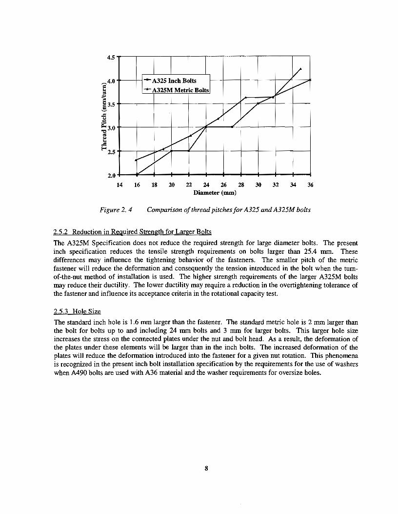
14 16 18 20 22 24 26 28 30 32 34 36 Diameter (mm)
Figure 2. 4 Comparison of thread pitches for A325 and A325M bolts
2.5.2 Reduction in Required Strength for Larger Bolts
The A325M Specification does not reduce the required strength for large diameter bolts. The present inch specification reduces the tensile strength requirements on bolts larger than 25.4 mm. These differences may influence the tightening behavior of the fasteners. The smaller pitch of the metric fastener will reduce the deformation and consequently the tension introduced in the bolt when the turnof-the-nut method of installation is used. The higher strength requirements of the larger A325M bolts may reduce their ductility. The lower ductility may require a reduction in the overtightening tolerance of the fastener and influence its acceptance criteria in the rotational capacity test.
2.5.3 llole Size
The standard inch hole is 1.6 mm larger than the fastener. The standard metric hole is 2 mm larger than the bolt for bolts up to and including 24 mm bolts and 3 mm for larger bolts. This larger hole size increases the stress on the connected plates under the nut and bolt head. As a result, the deformation of the plates under these elements will be larger than in the inch bolts. The increased deformation of the plates will reduce the deformation introduced into the fastener for a given nut rotation. This phenomena is recognized in the present inch bolt installation specification by the requirements for the use of washers when A490 bolts are used with A36 material and the washer requirements for oversize holes.
8

CHAPTER3
TEST PROGRAM
3.1 INTRODUCTION
Two general types of tests were conducted: one to measure the material characteristics of the bolts and nuts, and a second to study the performance of the bolt-nut-washer assembly. Chemistry composition, hardness, and direct tension tests were conducted on the bolts and nuts. Two different types of tests were performed on the bolt-nut-washer assembly: torque-tension-tum tests in setups of varying stiffness and tension-tum tests in solid plates. The method of testing and a description of these test setups is presented in this chapter. The results of the material tests are shown and compared with the applicable specifications. The results of the torque-tension-tum and tension-tum tests are presented in Chapter 4.
3.2 FASTENER PROPERTIES
Two different diameters of A325M bolts were examined in this project: 24 mm and 20 mm. The 24 mm bolts had lengths of70 mm, 100 mm, and 120 mm. The 20 mm bolts had lengths of 50 mm, 60 mm, and 70 mm. Chemistry composition, hardness, and direct tension tests were performed on the bolts and nuts to verify the mill test results.
3.2.1 Dimensions
The bolt and nut dimensions shown in Tables 3.1 and 3.2 are averages of three samples of each specimen type. The relevant ANSI dimension tolerances for each bolt and nut are presented in Tables 3.3 and 3.4 [1 and 2]. The measured dimensions all fall within the specified tolerances, with the exception of the major diameter of the threaded portion of each bolt. The major diameter exceeds the maximum ANSI tolerances.
3 .2.2 Chemistry Composition
Weight percent chemical analysis tests of the bolt and nut specimens were performed by both the mill and an independent testing laboratory. The results of these tests are presented in Tables 3.5, 3.6, and 3.7. The silicon content of the specimens was not determined by the independent testing laboratory. The ASTM Chemical Requirements [3 and 4] for the bolts and nuts tested in this analysis are shown in Table 3.8. The weight percent heat analysis results indicate that the fasteners and nuts meet the require specifications for composition. The chemical weight percentages are within the ASTM required ranges for all the specimens.
3.2.3 Hardness Tests
The bolt hardness was measured at 118 diameter intervals on two perpendicular axes through the shank of the bolt. The hardness readings on the nuts were taken on one of the flat sides that was machined down a few thousandths of an inch, following ASTM F606 recommendations. Rockwell hardness values and measurement locations for each bolt diameter are presented in Figure 3.1. The tests show that the
9

Table 3. 1 Measured Dimensions of Bolts (mm)
Bolt Body Major Width Width Height Thread Diameter Diameter Across Flats Across Comers Length
M24-3.0x70 23.901 23.673 40.767 46.660 15.723 41.097 M24-3.0 X 100 23.876 23.673 40.767 46.685 15.697 41.072 M24-3.0 X 120 23.901 23.724 40.665 46.660 15.773 48.082 M20-2.5x 50 19.990 19.787 33.299 38.151 13.132 35.636 M20-2.5x 60 19.914 19.685 33.350 38.176 13.132 35.789 M2072.5x70 19.914 19.685 33.350 38.202 13.132 35.662
Table 3. 2 Measured Dimensions of Nuts (mm)
Nut Width Width Thickness Minor Across Flats Across Comers Diameter
M24-3.0 GH GR10S 40.615 46.355 23.266 21.133 M20-2.5 GH GR10S 33.401 38.176 19.990 17.755
Table 3. 3 ANSI Bolt Dimension Requirements (mm)
Bolt Body Major Diameter Width Across Width Across Head Height Thread Diameter Flats Comers Length
Min. Max. Min. Max. Min. Max. Min. Max. Min. Max. Basic
M24-3.0x70 23.16 24.84 23.265 23.640 40.00 41.00 45.20 47.34 14.10 15.90 41 M24-3.0 X 100 23.16 24.84 23.265 23.640 40.00 41.00 45.20 47.34 14.10 15.90 48 M24-3.0 X 120 23.16 24.84 23.265 23.640 40.00 41.00 45.20 47.34 14.10 15.90 48 M20-2.5x 50 19.16 20.84 19.315 19.650 33.00 34.00 37.29 39.26 11.60 13.40 36 M20-2.5x60 19.16 20.84 19.315 19.650 33.00 34.00 37.29 39.26 11.60 13.40 36 M20-2.5x70 19.16 20.84 19.315 19.650 33.00 34.00 37.29 39.26 11.60 13.40 36
10

Table 3. 4 ANSI Nut Dimension Requirements (mm)
Nut Width Across Width Across Thickness Minor Diameter Flats Corners
Min. Max. Min. Max. Min. Max. Min. Max. M24--3.0 GH GR10S 40.00 41.00 45.20 47.34 22.9 24.2 21.112 21.612 M20-2.5 GH GR10S 33.00 34.00 37.29 39.26 19.4 20.7 17.644 18.094
Table 3. 5 Chemistry Composition of24 mm Bolts
Chemistry Composition Mill Test Lab Test Wt % Heat Analysis Heat 70mm 100mm 120mm
c 0.38 0.384 0.395 0.383 Mn 1.06 1.096 1.099 1.100 p 0.008 0.011 0.010 0.012 s 0.016 0.010 0.010 0.010 Si 0.21 - -B N. R. 0.0012 0.0012 0.0014
11

Table 3. 6 Chemistry Composition of20 mm Bolts
Chemistry Composition Mill Test Lab Test Wt % Heat Analysis Heat 50mm 60mm 70mm
c 0.36 0.38 0.38 0.38 Mn 1.09 1.14 1.14 1.16 p 0.007 0.010 0.009 0.009 s 0.023 0.024 0.023 0.023 Si 0.23 - - -B N. R. 0.0004 0.0003 0.0003
Table 3. 7 Chemistry Composition of 6H GRJOS Nuts
Chemistry Composition Mill Test Lab Test Wt% Heat Analysis M24-3.0 M20-2.5 M20-2.5
c 0.43 0.44 0.45 Mn 0.67 0.66 0.69 p 0.009 0.007 0.008 s 0.022 0.016 0.022 Si 0.24 0.20 -
Table 3. 8 ASTM Chemical Requirements for Bolts and Nuts
Chemistry Composition A325M Type 1 Bolt A563M Nut Wt % Heat Analysis Alloy Steel 1 OS Property Class
c 0.30-0.52 0.55 max. Mn 0.60 min. 0.30 min. p 0.035 max. 0.04 max. s 0.040 max. 0.05 max. Si 0.15-0.35 -B - -
12

M24-3.0 x 70 Bolt M24-3.0 x 100 Bolt
23.7 24.5
• • 22.3 23.2
• • 23.8 22.5 12.3 21.5 22.0 25.3 24.0 22.8 22.5 23.5
• • • • • • • • • • 22.5 24.0
• • 23.5 25.3
• • 25.0 28.2
• •
M24-3.0 x 120 Bolt M20-2.5 x 50 Bolt
• 24.5 27.3
• • 22.2 23.3
• • 24.2 23.2 23.3 21.6 23.3 28.0 21.0 23.2 24.0 29.0
• • • • • • • • • • • • 22.5 23.5
• • 25.6 25.2
• • 28.6 26.5
• •
M20-2.5 x 60 Bolt M20-2.5 x 70 Bolt
Figure 3. I Rc hardness test values for M24 and M20 A325M bolts
13

Table 3. 9 Average Rc Hardness Test Results for M24 and M20 A325M Bolts and Nuts
Specimen Mill1/4 Diameter Lab 1/4 Diameter Hardness Hardness
M24-3.0 X 70 Bolt 23.1 23.3 M24-3.0 X 100 Bolt 27.2 24.7 M24-3.0 X 120 Bolt 28.7 24.4 M24-3.0 6H GR10S Nut 29.1 30.4 M20-2.5 X 50 Bolt 26.2 27.4 M20-2.5 X 60 Bolt 27.9 25.7 M20-2.5 X 70 Bolt 27.2 25.9 M20-2.5 6H GR1 OS Nut 29.6 29.5
hardness is higher on the outer portion of the bolt, but these results are not abnormal. This hardness pattern indicates that the bolts were properly heat treated.
The average 1/4 diameter hardness values for each bolt and nut are given in Table 3.9, along with the average mill test results. The lab bolt hardness data represents the average of the readings taken at 1/4 diameter from the center of the bolt. All hardness values are Rockwell C.
ASTM specifies a minimum Rockwell Hardness of 23 and a maximum Rockwell Hardness of 34 for A325M bolts. For grade lOS nuts, ASTM A563M specifies a minimum Rockwell Hardness of 26 and a maximum Rockwell Hardness of 38 (3 and 4]. The average hardness values for both mill and lab tests indicate that the bolts and nuts meet these requirements.
3.2.4 Direct Tension Tests
The purpose of the tension tests of the full size bolts was to determine the tensile strengths of the bolt material and bolt-nut assembly. The direct tension tests were conducted in a Skidmore-Wilhelm Bolt Calibrator, as shown in Figure 3.2. Each bolt type was placed in the calibrator with the nut flush with the end of the bolt. During the test, the pressure in the calibrator was increased by hand-pumping hydraulic fluid into the calibrator until the bolt failed. The ultimate tensile strengths shown in Table 3.10 are the averages of three tests for basic bolt material strength. The range of test values is also indicated in this table. All bolts failed by fracturing in the threaded portion of the shank. The wedge tensile tests run by the manufacturer are included for comparison.
The results from the lab direct tension tests compare favorably with the tensile strengths from the mill reports, with the exception of the M24-3.0 x 70 and M20-3.0 x 70 bolt results. For these bolts, the tensile strengths determined through testing in the lab were significantly higher than the mill results. However, all recorded tensile strengths were greater than the ASTM specified minimum tensile strengths of 293 kN for M24 x 3.0 bolts and 203 kN for M20 x 2.5 bolts (3 and 4].
14

Figure 3. 2 Skidmore-Wilhelm bolt calibrator used for direct tension tests
Table 3. 10 Ultimate Tensile Strength ( F u) of Bolts
Bolt Average Mill FuJkNJ Average Lab Fu (kN) M24-3.0 X 70 330.0±0.2 348.5±3.0 M24-3.0 X 100 348.5±2.0 357.1 ± 3.0 M24-3.0 X 120 358.3±4.6 360.8±4.5 M20-2.5 X 50 230.8± 5.9 230.0±3.0 M20-2.5 X 60 236.4± 1.2 241.6±3.0 M20-2.5 X 70 238.3+0.6 259.6+ 3.0
15

3.3 TORQUE-TENSION-TURN TESTS
The stiffness and ductility of a bolt are affected by the grip length, number of threads within the grip, and the lubrication of the bolt-nut-washer assembly, as discussed in Chapter 2. In order to test each bolt at the maximum and minimum possible grip length, two grip conditions were used: nut flush with the end of the bolt and nut 3 turns from the end of the threads near the shank. The 3 turns grip condition was set as the minimum grip length to ensure that during a test to failure, there was adequate thread length to tum the nut to fail the bolt.
3.3.1 Bolt Matrix
The bolt matrix for the torque-tension-tum test is shown in Table 3 .11. All testing was performed using hand wrenches to tighten the fasteners. The flush grip condition indicates that the bolt was tested with the nut flush with the end ofthe bolt, as displayed in Figure 3.3. The 3 turns grip condition indicates the bolt was tested with the nut 3 turns back from the position when the nut cannot be rotated at the end of the threads. This minimum grip length condition is displayed in Figure 3.4.
Two bolt conditions are listed in the torque-tension-tum bolt test matrix: lubricated and weathered. The lubricated condition denotes that the bolts, nuts, and washers were tested as received from the producer. The weathered condition denotes that the bolts, nuts, and washers were dipped in water and dried in air each of the two days prior to testing.
3.3.2 Load Cell- Solid Plate System
A test setup was built along with an automated data acquisition system to perform the torque-tension-tum tests. The test setup is shown in Figure 3.5. A flat shear type 445 kN (100 kip) load cell was mounted onto a 50.8 mm thick milled steel plate. A 101.6 mm diameter section at the center of the steel plate was
Table 3. 11 Torque-Tension-Turns Bolt Test Matrix
Diameter (mm) Length (mm) Grip Grip Length (mm) Condition # 24 70 Flush 46 Lubricated 3
70 Flush 46 Weathered 3 100 3 Turns 63 Lubricated 3 100 3 Turns 63 Weathered 3 100 Flush 76 Lubricated 3 100 Flush 76 Weathered 3 120 3 Turns 75 Lubricated 3 120 3 Turns 75 Weathered 3 120 Flush 96 Lubricated 3 120 Flush 96 Weathered 3
20 50 Flush 30 Lubricated 3 50 Flush 30 Weathered 3 60 Flush 39 Lubricated 3 60 Flush 39 Weathered 3 70 Flush 50 Lubricated 3 70 Flush 50 Weathered 3
16

9 10 11 12
Figure 3. 3 Example of flush grip for a 24 mm x 70 mm bolt
Figure 3. 4 Example of three turns grip for a 24 mm x 70 mm bolt
17

Figure 3. 5 Side view of load cell -flat plate system
Figure 3. 6 Front view of load cell -flat plate system
18

Figure 3. 7 Rear view of load cell -flat plate system
bored down to a 25.4 mm thickness. A 26 mm diameter hole was drilled in the center of the borehole to accommodate the shank of the bolt. The bolt, nut and washer were installed into the load cell - flat plate setup. A threaded insert in the load cell permitted length adjustment so that both 24 mm x 120 mm flush (96 rnm grip) and 3 turns (75 rnm grip) conditions could be tested. A long socket extension was used which went from the installation wrench (a) supported by two bearings (b) to a 1627 N-m (1200 ft-lb) torque load cell and tum counter (c) with electronic output, through a final bearing for alignment, to a torque multiplier (d) to reduce the input torque required (e). The connection between the load cell (f) and the flat plate (g) is shown with more detail in Figures 3.6 and 3.7.
3.3.3 Load Cell Box System
To accommodate shorter bolts, the test setup was altered to allow for grip lengths ranging from 96 rnm to 46 mm. The load cell box system is displayed is Figure 3.8. This setup provided a relatively stiff fixture. The 24 mm x 120 mm flush (96 rnm grip) and 3 turns (75 rnm grip) were tested in this test setup to allow for comparison with Load Cell - Solid Plate System results. Two stiff steel plates were placed in between the load cell and the original mounting plate to provide 252 rnm of clear space. The upper 91 mm x 252 mm plate was bolted into the top three holes of the load cell mounting pattern, while the lower 75 mm x 360 mm plate was bolted into the lower 3 holes of the mounting pattern to allow for a vertical interior clearance of 103 rnm. A special apparatus was machined to tum into the 70 rnm (2.75 in) threaded core of the load cell, as shown in Figure 3.8. The opposite end of the apparatus was designed to accept a small 75 mm diameter threaded insert containing the fixed bolt head, as shown in Figures 3.9 and 3.10. To test the limiting grip length of this setup ( 46 mm), the thickness of the bolted portion of the insert was minimized to 12 mm.
19

Figure 3. 9
Figure 3. 8 Load cell box system
Grip length adjustment apparatus for load cell box system
20
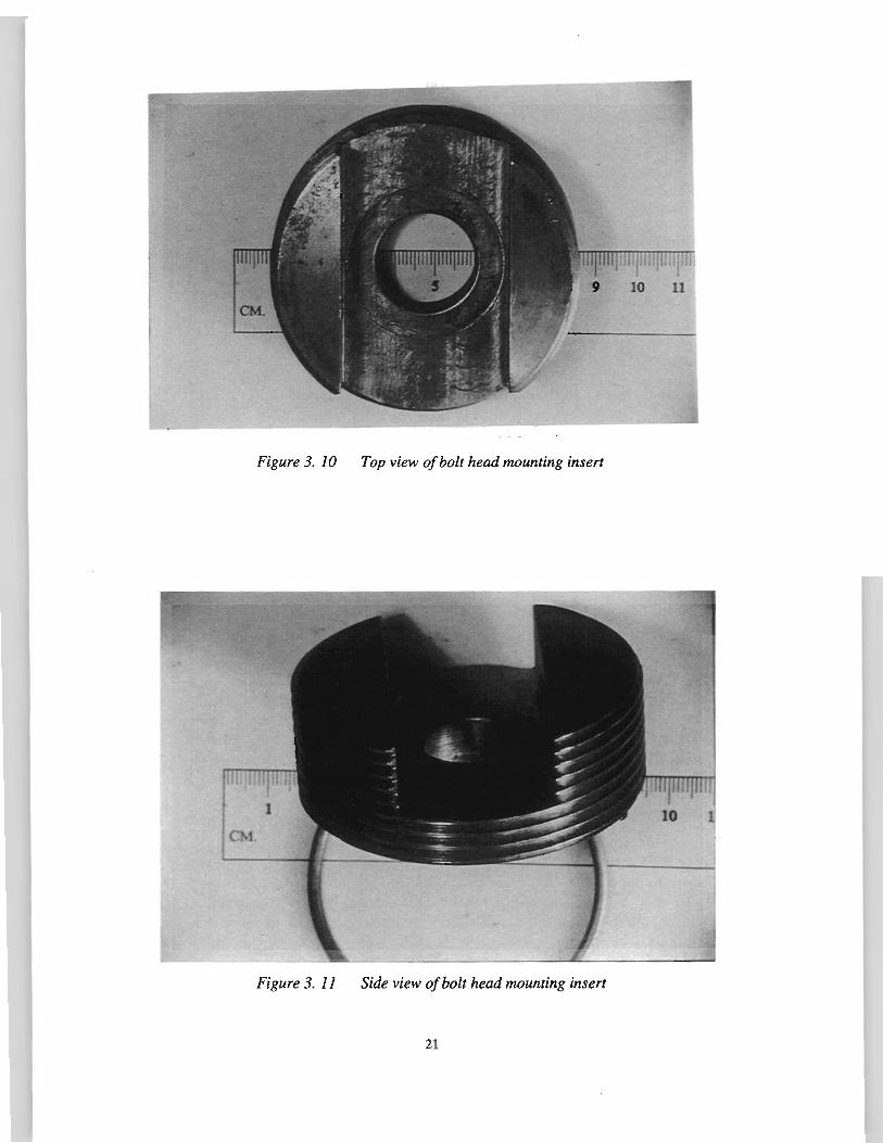
Figure 3. 10 Top view of bolt head mounting insert
Figure 3. 11 Side view of bolt head mounting insert
21

Figure 3. 12 Short grip Skidmore test setup
3.3.4 Short Grip Skidmore Test Setup
The short grip lengths of the 20 mm x 60 mm and the 20 mm x 50 mm bolts could no be tested in either of the load cell test setups. A short grip Skidmore-Wilhelm bolt calibrator (MS Model) was used to test these bolts. The Skidmore was substituted into the setup in place of the load cell box, as shown in Figure 3.12. A pressure transducer was connected to the bolt calibrator to allow for direct computer readings of the tensile load.
3.3.5 Test Procedure
The scanning capabilities of the data acquisition system enabled the simultaneous recording of tension, torque, and turns using a personal computer. After the fastener assembly was hand tightened into position, the system was zeroed and set into recording mode. A manual wrench was then used to tighten the bolt. Each test was terminated when the bolt failed or when the number of turns exceeded the recording limit of the system (2.5 turns from the starting position). The same procedure was used in all torque-tension-tum tests.
3.4 TxDOT TESTS
Three replicate rotational capacity tests were performed on each set of fasteners in the torque-tensiontum test matrix. The rotational capacity test was slightly modified from the standard test in order to provide additional information. An air-powered nut runner and torque multiplier were used to tum the nut in 60° increments in a Skidmore-Wilhelm bolt calibrator from an assumed snug tension equal to 10 % of the minimum bolt tensile strength until failure. The tension and nut rotation were recorded at each increment. The M Model Skidmore was used to test all bolts except for the 50 mm and 60 mm lengths of the 20 mm bolts. As with the torque-tension-tum tests, the MS Model Skidmore was used to test these bolts.
22

Table 3. 12 Solid Plate Test Bolt Matrix
Diameter (mm) Length (mm) Grip Grip Length (mm) Condition # 24 70 3 Turns 32 Lubricated 3
70 Flush 46 Lubricated 3 120 3 Turns 75 Lubricated 3 120 Flush 96 Lubricated 3
20 50 Flush 30 Lubricated 3 70 3 Turns 37 Lubricated 3 70 Flush 50 Lubricated 3
3.5 SOLIDPLATETESTS
3.5.1 Bolt Test Matrix
The bolt matrix for the solid plate tension-tum test is shown in Table 3.12. These bolts were tested in A572 Grade 50 material plates machined to the various grip lengths, with a hole diameter equal to the bolt diameter plus 2 mm.
3.5.2 Determining Tension-Elongation Relationship
The first step in the solid plate test was to produce tension vs. elongation calibration curves for each bolt and grip length to be examined. The tension-elongation relationships are used to determine the tension in the solid plate tests. These curves were developed by tightening each bolt in a Skidmore-Wilhelm bolt calibrator and measuring bolt elongation and tension at approximately every 300 of nut rotation, until the bolt failed. All calibration test bolts were end drilled to allow for seating of dial gauge metal points at each end. The elongation of each bolt was measured with a C frame mounted 0.0001 in dial gauge, as shown in Figure 3.13.
Three tension-elongation calibrations were performed on each bolt grip length condition. Linear regression was used to calculate the slope of the elastic region of the tension vs. elongation curves. The average of the slopes from three tension-elongation tests was taken as the elastic relationship. The average tension per elongation slope was multiplied by the elongation values in the elongation vs. rotation data to develop the elastic portion of the tension vs. rotation relationship for each bolt.
3.5 .3 Determining Elongation-Rotation Relationship
Each bolt was tightened to failure in a solid plate with a thickness equal to the grip length. The elongation was measured at 7.50 nut rotation increments in the elastic region. Larger rotation increments were used as the elongation-rotation relationship became more linear. The solid plate test setup is displayed in Figure 3.14. A summary of the test setups used for each bolt grip condition is presented in Table 3.13.
23

Figure 3. 13 C Frame dial gauge
Figure 3. 14 Solid plate test setup
24
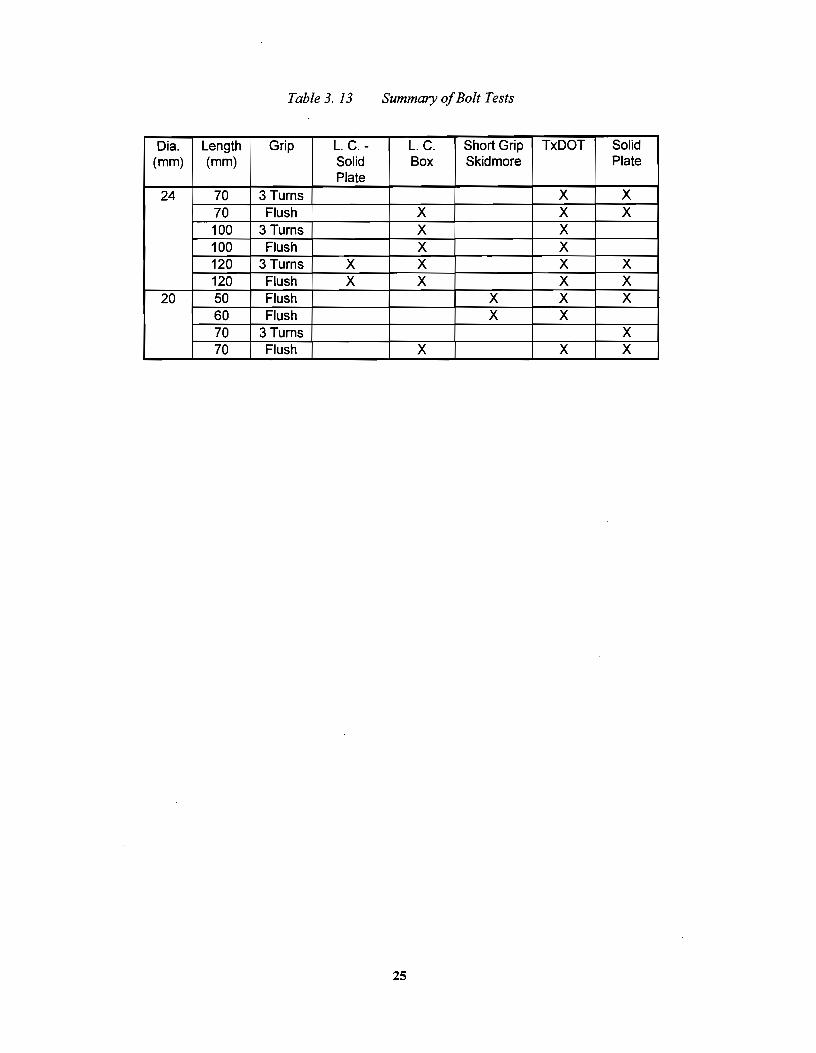
Table 3. 13 Summary of Bolt Tests
Dia. Length Grip L. C.- L. C. Short Grip TxDOT Solid {mm) {mm) Solid Box Skidmore Plate
Plate 24 70 3 Turns X X
70 Flush X X X 100 3 Turns X X 100 Flush X X 120 3 Turns X X X X 120 Flush X X X X
20 50 Flush X X X 60 Flush X X 70 3 Turns X 70 Flush X X X
25


CHAPTER4
DATA PRESENTATION
4.1 INTRODUCTION
The results of the torque-tension-tum tests and the tension-tum tests were analyzed with respect to the current installation requirements of the AASHTO tum-of-the-nut procedure and rotational capacity test. Two different snug conditions and the output from test setups of differing stiffness were analyzed and utilized to best determine the installation requirements for the A325M metric bolts. Alternate installation requirements are presented when the current AASHTO requirements for inch bolts were not satisfactory for the A325M metric bolts. Final recommendations for changes to the current bolt specification are given in Chapter 5.
4.2 SNUG CONDITION
The AASHTO Specification states the a snug tight condition "may be attained by a few impacts of an impact wrench or the full effort of a man using an ordinary spud wrench". This definition leaves no quantifiable value of snug in terms of fastener tension or torque. A man using an impact wrench could conceivably apply a much larger torque than a man using a spud wrench. The snug definition becomes more ambiguous when considering the variance of"full effort" from one man to another. However, the snug condition is very important to the effectiveness of the tum-of-the-nut method. The specified nut rotations to reach the required tension in the fastener are applied after the bolt has been tightened to a snug condition.
The previous research on inch bolts used a snug tension equal to I 0% of the minimum specified tensile strength of the fastener to determine the nut rotation requirements [11]. For the A325M metric bolt research project, two snug tension conditions were examined: 10% of the minimum specified tensile strength (20.3 kN for the 20 mm bolts and 29.3 kN for the 24 mm bolts) and a fastener tension of 44.48 kN (10 kips). Figures 4.1 and 4.2 show the torque required to reach these snug tension conditions for each bolt tested in a torque-tension-tum test. These plots include data from different test setups ranging from load cell - solid plate to short grip Skidmore. As expected, the test setup did not influence the torque-tension relationship The data also includes bolts tested in the as received and weathered conditions. The removal of lubrication did not have any appreciable effect on the torque-tension relationship. The torque required for the 20 mm bolts was less than the torque required for the 24 mm bolts for both snug conditions.
The maximumtorque a man can apply using an ordinary spud wrench was estimated to be 203 N-m (150 ft-lb). The torques required to produce the 10% of minimum specified tensile strength snug condition are representative of this 150 ft-lb maximum torque input. The maximum and minimum torques were 273 Nm (201 ft-lb) and 107N-m (79 ft-lb), respectively.
27

Torque Required to Reach 10% of Minimum Specified Tens~le Strength
300~----------------------------------------------.
250
_200 e I z
';;'ISO
= ~ 0 E-<100
50
0
Figure 4. 1
1 As Received
0 Weathered
Torque required to reach 10% of minimum specified tensile strength
Torque Required to Reach 44.48 kN Tension in Fastener
350T---------------------------------------------~
300
250
-e I 200 ~ ljj
&tso '"" 0
E-< 100
50
0
Figure 4. 2
1 As Received
0 Weathered
Torque required to reach 44.48 kN tension in fastener
28

The torques required to reach the 44.48 k:N snug tension condition were significantly higher than the torques required to reach 10% of the minimum specified tensile strength. The 44.48 kN snug torques ranged from 210 N-m (155 ft-lb) and 343 N-m (253 ft-lb). All of these torques are above the estimated maximum torque input of203 N-m (150 ft-lb). The 44.48 kN snug condition requires torques that are not plausible for a man with a spud wrench. However, this snug condition can be used to estimate the maximum snug when using an impact wrench.
In addition, the 44.48 k:N snug tension is more likely to be on the linear-elastic portion of the tension-turn curve. Figure 4.3 shows a graph of the initial part of a tension-turn load curve up to the minimum specified fastener tension for a 20 mm x 70 mm lubricated flush grip bolt in the load cell box test setup. The graph clearly shows that the 44.48 kN snug point lies on the linear elastic portion of the loading curve. The 20.3 k:N snug point occurs before the curve becomes linear. Figure 4.4 indicates similar results for the same type of bolt tested in a solid plate. In this case, the 20.3 kN point is closer to the start of the linear portion of the tension-turn curve. These results are typical for all bolts tested in the torquetension-turn and solid plate tests. The 44.48 k:N snug tension condition provides a more uniform starting point for examining the relative behavior of bolts in the various test setups because the point is on the linear-elastic portion of the curve. Using a snug point that occurs before the curve becomes linear would make determination of the influence of the test setups on bolt behavior difficult. The amount of'play" or initial looseness in the test setup and the bolt-nut-washer-assembly at the start of loading varies from test to test and setup to setup. As a result, the length of the curve before the linear portion is different for each bolt tested.
In this research, the ultimate rotational capacity of each bolt was measured from the 44.48 kN snug. This tension represents the estimated maximum snug condition in the field. Conversely, the nut rotations
Initial Tension-Turn Curve for a 20 x 70 Flush Grip Bolt up to Minimum Specified Fastener Tension in Load Cell Box
1~~--------------------------------------------~
140 ••
~120 / Z100 { c /• §~ ~ ~ L a:s 60 /.
f-o 40 --~4~ _______ L _____ _ •
20 20.3 kN •••• ;;... ------- ~-----------• •
0 - • .. • • • • ~~~~~~~-1----~---1----~--~~--~--~ 0
Figure 4. 3
0.1 0.2 0.3 0.4 0.5 0.6 0.7 ·0.8 0.9
Turns
Initial tension-tum curve for a 20 x 70 flush grip bolt up to minimum specified fastener tension in load cell box
29

Initial Tension-Turn Curve for a 20 x 70 Flush Grip Bolt up to Minimum Specified Fastener Tension in a Solid Plate
160~--------------------------------------------~
140
120 -~
z1oo ~ = 80 !.e ..,.,
5 E-c ' ~ I
~---- -4~8~------ -1--/ 40
2o.3 kN I 20 -~ - - - - - - - - - - - ...... - - - - -• • • • 0+----------~·-----·--~·~·------~------~·------~·------~
0
Figure 4. 4
0.05 0.1 0.15
Turns 0.2 0.25
Initial tension-tum curve for a 20 x 70 flush grip bolt up to minimum specified fastener tension in a solid plate
0.3
required to reach the minimum specified fastener tension were measured from the I 0% of minimum specified tensile strength snug condition. This condition represents the estimated minimum snug condition in the field. The 44.48 kN snug condition was also used to compare the initial stiffness of each bolt in the different test setups.
4.3 EFFECT OF WEATHERING UPON LUBRICATION PERFORMANCE
The results of all testing indicated no significant difference in bolt behavior between those bolts that were tested in the as received condition and those that were weathered in the laboratory before testing. Table 4.1 compares the average nut factors for the as received and weathered bolts tested in the torque4ensiontum tests. The nut factors indicate that the installation torques for each of the lubrication conditions were remarkably similar from the snug point (as presented in Figures 4.1 and 4.2) up to and including the maximum torque in the test. In addition, there was no significant difference in ductility as measured by turns to failure. Table 4.2 compares the average turns to failure in the torque-tension-tum tests for each lubrication condition. The turns to failure were measured from a snug tension equal to 44.48 k:N. The results indicate that the lubricant supplied on the as received fastener was not significantly degraded by the simulated weathering done in the laboratory.
4.4 BOLT PERFORMANCE IN DIFFERENT TEST SETUPS
Figures 4.5 through 4.9 graphically contrast the performance of bolts tested in the solid plate setup with the results of replicate tests in other test setups. The plots display the effects of the wide spectrum of test setup stiffnesses upon the rotational performance of the bolts. In each case, the bolt tested in the solid plate had the highest initial stiffness and the lowest ductility, or ultimate rotational capacity. The bolts
30

Table 4. 1 Average Turns to Failure for Torque-Tension-Turn Tests
Diameter Length Grip Test Setup Average Turns to Failure (mm} (mm} As Weathered
Received 24 70 Flush Load Cell Box 1.80 1.92
100 3 Turns Load Cell Box 1.26 1.28 100 Flush Load Cell Box 1.69 1.62 120 3 Turns Load Cell Box 1.33 1.38 120 3 Turns L. C.- Solid Plate 1.42 1.38 120 Flush Load Cell Box 2.20 2.22 120 Flush L. C.- Solid Plate 2.22 2.12
20 50 Flush Short Grip 2.19 2.06 Skidmore
60 1 =Grip 1.82 1.76 more
70 Flush Load Cell Box 1.76 1.78
Table 4. 2 Average Nut Factors for Torque-Tension-Turn Tests
Diameter Length Grip Average Nut Factor (mm} (mm) As Received Weathered
24 70 Flush 0.225 0.208 100 3 Turns 0.212 0.200 100 Flush 0.211 0.211 120 3 Turns 0.206 0.203 120 Flush 0.206 0.207
20 50 Flush 0.200 0.228 60 Flush 0.241 0.251 70 Flush 0.224 0.240
31

Relative Performance of 24 x 70 Flush Grip Bolts in Different Test Setups
01-----~----~----~----~----~----~-----+----~ 0.00
Figure 4. 5
-
0.25 0.50 0.75 1.00 1.25 1.50
Turns (from 44.48 kN Snug)
1.75 2.00
Relative performance of 24 x 70 flush grip bolts in different test setups
~200+--+~-M~--~-----= 0 ";j 150 = +--T~~~------~----~,-------,-----~~------~ Q,)
~ 100~~~--~------~------~------~------~------~
0;-------+-------~----~~----~-------+-------f 0.00
Figure4. 6
0.25 0.50 0.75 1.00 1.25 1.50
Turns (from 44.48 kN Snug)
Relative performance of 24 x 120 three turn grip bolts in different test setups
32

Relative Performance of 24 x 120 Flush Grip Bolts in Different Test Setups
0+----r--~----~--~---r--~----+---~---+--~ 0.00 0.25 0.50 0.75 1.00 1.25 1.50 1.75 2.00 2.25 2.50
Turns (from 44.48 kN Snug)
Figure 4. 7 Relative performance of 2 4 x 120 flush grip bolts in different test setups
250
200
-~ 150 -= .!: "' 100 ~
50
0
Relative Performance of20 x SO Flush Grip Bolts in Different Test Setups
I I
(..--~ - i -
·; -So lid Plate -Short Grip Skidmore
v •
I - TxDOT Short Grip Skidmore
I I
i I I
. .
I
~~-I
•
I i
0.00 0.25 0.50 0.75 1.00 1.25 1.50 1.75 2.00 2.25
Figure 4. 8
Turns (from 44.48 kN Snug)
Relative performance of 20 x 50 flush grip bolts in different test setups
33

200
-
Relative Performance of20 x 70 Flush Grip Bolts in Different Test Setups
~ 150~~-.~--~-----r~~~~==~~~-----r----! -= = ·~ 1001t~~~----i-----~-~~~~~~~---~-----1----~ E-t
0+-----+-----+-----+-----+-----+-----+---~+---~ 0.00 0.25 0.50 0.75 1.00 1.25 1.50 1.75 2.00
Turns (from 44.48 kN Snug)
Figure 4. 9 Relative performance of 20 x 70 flush grip bolts in different test setups
Example of Rotational Stiffness Calculation for 20 x 70 Flush Grip Bolt in Load Cell Box Test Setup
200~---------------------------------------------,
180
160 _140 ___________________ --r-~ 120 -§ 100 L\T
0.7 x Minimum Specified Tensile Strength= 142.1 kN
! : -----------·~~~~ _____ __!_ _____ _
•
~ ~~ • • • !+--L\N --+i
20 • • I I
•· I I • I I
• • • •
•• # •
0~~~~~~~-T----~--~----r----r--~~·---r--~ 0 0.1 0.2 0.3 0.4 0.5
Turns 0.6 0.7 0.8 0.9 1
Figure 4. 10 Example of rotational stiffness calculation for 20 x 70 flush grip bolt in load cell box test setup
34

tested in the TxDOT Skidmore test setups had the lowest initial stiffness, with the exception of the 24 mm x 70 mm and the 20 mm x 50 mm bolts. These bolts had essentially the same stiffness in the load cell box and the TxDOT Skidmore test setups.
The stiffness of a multiple ply connection is expected to fall between the hydraulic bolt calibrator and solid plate extremes. The results from the test setup with the lowest stiffness were used to establish nut rotation requirements because a bolt tested in this setup requires the highest number of turns to reach a specified tension. Similarly, the data from the solid plate test setup was used to check ultimate rotational capacity limitations because the reduced rotational ductility of a bolt tested in this setup results in the lowest number of turns to failure.
The inelastic portion of the tension-tum curve was found to be independent of the test setup. The 24 x 120 flush grip bolt tension-tum curves in Figure 4.7 illustrate the fact that the nut rotations in the inelastic range of the solid plate and TxDOT tests are approximately equal (1.54 turns and 1.56 turns), despite large differences in initial stiffness. The inelastic behavior of the bolt is not a function of the type of test setup.
4.5 ROTATIONAL STIFFNESS
The relationship between tension and nut rotations from a snug tension of 44.48 kN to the minimum specified fastener tension for a given bolt is reasonably linear. Therefore, the"rotational stiffness" of any bolt can be calculated by using linear regression to determine the slope of the tension-tum curve between these points. The slope of the linear portion of the tension-tum curve is defined by the following equation,
Rotational Stiffness = .<1 T I LlN (4.1)
where .<1T is the change in fastener tension and LlN is the change in nut rotation, as depicted in Figure 4.10.
The rotational stiffnesses for bolts tested in the torque-tension-tum tests are compared with the solid plate test results in Figures 4.11 and 4.13. For the 50 mm and 70 mm bolts (both 20 mm and 24 mm diameters), the rotational stiffnesses were 4 to 5 times higher in the solid plate than in the short grip Skidmore and load cell box tests. For the 24 mm x 120 mm bolts tested in the solid plates, the rotational stiffnesses were approximately 2.2 times larger than the stiffnesses from the load cell box test setup, and 1.5 time times larger than stiffnesses from the load cell - flat plate test setup. As expected, the graphs also indicate an increase in rotational stiffness for shorter grip lengths in the solid plate tests.
Figures 4.12 and 4.14 show the influence of grip length on rotational stiffness in the torque-tension-tum tests. As with the solid plate results, the load cell - solid plate, load cell box, and short grip Skidmore test results indicate an inverse relationship between rotational stiffness and grip length. It should be noted that the TxDOT Skidmore results are not included because the linear portions of these curves do not contain enough points to accurately define a slope.
4.6 NUT ROTATION
The number of nut rotations required to reach the minimum specified fastener tension from a snug tension equal to 10% of the minimum specified tensile strength was calculated for every bolt tested. The
35

2250
2000 -= 1750 -= ~ 1500 ~ - 1250 1:1}
1:1}
11.1
!5 1000 .....
750 00 -= = 500 .s ..... = 250 ..... c c:: 0
Figure 4. 12
1000
900 -= -= ~ 800
-1:1}
700 1:1}
11.1
5 ..... 00 600 -; = c -..... 500 = ..... c c::
400
Figure 4. 11
Comparison of Rotational Stiffnesses for 24 mm Bolts in Torque-Tension-Tum and Solid Plate Tests
0 Load Cell Box
• Load Cell- Solid Plate
24 x 70 Flush 24 x 120 3 Turns 24 x 120 Flush
Comparison of rotational stiffnesses for 24 mm bolts in torquetension-turn and solid plate tests
Comparison of Rotational Stiffnesses for 24 mm Bolts in Load Cell- Solid Plate and Load Cell Box Tests
Load Cell Box
IIJI Load Cell - Solid Plate
N x70F1usb 24 x 100 3 Turus 24 x 100 Flusb N x 120 3 Torus 24. no Flosb
Comparison of rotational stiffnesses for 24 mm bolts in load cell solid plate and load cell box tests
36
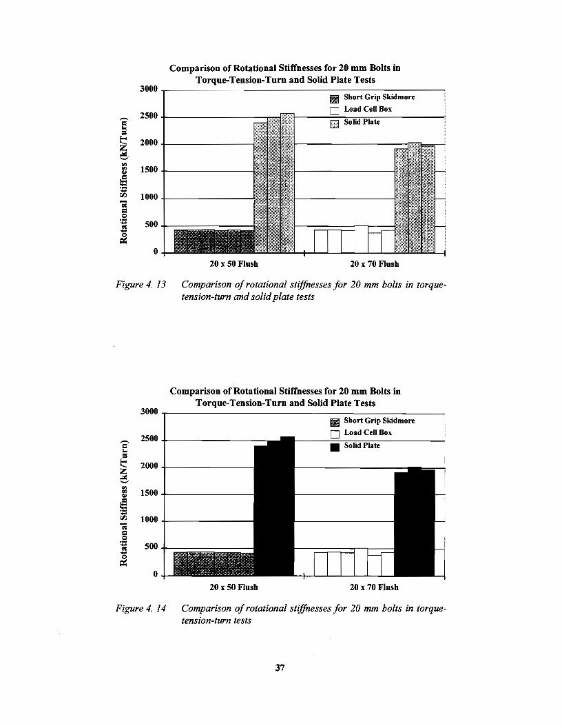
3000
- 2500 E = ~ 2000 ..::.:: -"' 1500 "' <1.1
!5 -00 1000 -~ = Q .... 500 .....
.! &
0
Figure 4. 13
3000
- 2500 = t..
= ~ 2000 z ..::.:: -"' "' 1500 <1.1
IS .... .... 00 1000 -; = .E .... 500 ~ .... &
0
Figure 4. 14
Comparison of Rotational Stiffnesses for 20 mm Bolts in Torque-Tension-Tum and Solid Plate Tests
111 Short Grip Skidmore
0 Load Cell Box
UEJ Solid Plate
20 x 50 Flush 20 x 70 Flush
Comparison of rotational stiffnesses for 20 mm bolts in torquetension-turn and solid plate tests
Comparison of Rotational Stiffnesses for 20 mm Bolts in Torque-Tension-Tum and Solid Plate Tests
Ill Short Grip Skidmore
0 Load CeO Box
•
20 x 50 Flush 20 x 70 Flush
Comparison of rotational stiffnesses for 20 mm bolts in torquetension-turn tests
37

snug tension was equal to 20.3 kN for the 20 mm bolts and 29.3 kN for the 24 mm bolts. As stated previously, the bolts tested in the lower stiffness test setups required the highest number of nut rotations. The nut rotation requirements for the load cell - flat plate, load cell box, short grip Skidmore, and Tx.DOT Skidmore tests are presented in Figures 4.15 through 4.22. In each graph, the nut rotation axis has 300 degree gridline increments.
The 24 mm x 120 mm 3 turn and flush grip results (Figures 4.18 and 4.19) indicate that the required number of turns to reach the minimum specified fastener tension decreases as the stiffness of the test setup increases, as expected. The influence of test setup on the required nut rotations is minimal for the other results because the overall stiffnesses of the load cell box and Skidmore test setups examined in these cases are about the same.
A comparison of the required nut rotations for the two grip conditions for the 24 mm x 100 mm bolts (Figures 4.16 and 4.17) and the 24 mm x 120 mm bolts (Figures 4.18 and 4.19) shows that the 3 turns bolts required slightly less turns than the flush bolts. An examination of the required nut rotations for the 20 mm bolts (Figures 4.20 through 4.21) also indicates an increase in the required turns for longer grip lengths in the same test setup.
4.7 ULTIMATE NUT ROTATIONAL CAPACITY
The ultimate nut rotational capacity was determined in the stiffest test setup, the solid plate, which provides the least bolt ductility, or lowest number of turns to failure. The values of rotational capacity in the solid plate test were determined using a 44.48 kN snug condition. The number of turns to failure for each set of bolts tested in the solid plate setup are plotted in Figure 4.23. The lowest rotational capacity recorded was 1.074 for one of the 20 mm x 70 mm 3 tum grip bolts. This value is nearly 2/3 turn less
Required Nut Rotations to Reach Minimum Specified Fastener Tension for 24 x 70 Flush Grip Bolts
0.417 ~-------------------------,
~ 0.250 .s -C!ll
~ 0.167 -= z 0.083
0.000 +---'---'---......_--1. _ __.__....__
24 x 70 Flush
0 Load Cell Box
1111 TxDOT Skidmore
Figure 4. 15 Repaired nut rotations to reach minimum specified fastener tension for 24 x 70 flush grip bolts
38

"" = Q ·--= -~ -= z
0.417
0.333
0.250
0.167
0.083
Required Nut Rotations to Reach Minimum Specified Fastener Tension for 24 x 100 3 Turn Grip Bolts
0 Load Cell Box
0.000 +---'---'----1.---'--..1.....---i.--
24 x 100 3 Turns
Figure 4. 17 Required nut rotations to reach minimum specified fastener tension for 24 x 100 three turn grip bolts
Required Nut Rotations to Reach Minimum Specified Fastener Tension for 24 x 100 Flush Grip Bolts
0.417 .,...----·-------==---=----::~~----------, D Load Cell Box IIIJ TxDOT Skidmore
0.333
~ 0.250 .~ -!! ~ 0.167 -i
0.083
24 x 100 Flush
Figure 4. 16 Required nut rotations to reach minimum specified fastener tens ion for 24 x I 00 flush grip bolts
39

Required Nut Rotations to Reach Minimum Specified Fastener Tension for 24 x 120 3 Turn Grip Bolts
0.417 .....-------------------------, Load Cell- Solid Plate
0 Load Cell Box 0333+------------------~
• TxDOT Skidmore
24 x 120 3Turns
Figure 4. 19 Required nut rotations to reach minimum specified fastener tension for 24 x 120 three tum grip bolts
Required Nut Rotations to Reach Minimum Specified Fastener Tension for 24 x 120 Flush Grip Bolts
Load Cell - Solid Plate
0 Load Cell Box 0333+---------------~
• TxDOT Skidmore
a o.2so +----.sa -~ & 0.167 -= z
0.083
0.000
24 x 120 Flush
Figure 4. 18 Required nut rotations to reach minimum specified fastener tension for 24 x 120 flush grip bolts
40

"" = .s: .... ~ ..... 0
Cll: .... = z
0.417
0.333
0.250
0.167
0.083
Required Nut Rotations to Reach Minimum Specified Fastener Tension for 20 x 50 Flush Grip Bolts
Sbort Grip Skidmore
IIJ TxDOT Short Grip Skidmore
0.000 +-_..__...___......___. _ _...__....__
20 x 50 Flusb
Figure 4. 21 Required nut rotations to reach minimum specified fastener tension for 20 x 50 flush grip bolts
"" = .s: ..... ~ ..... 0
Cll: .... = z
0.417
0.333
0.250
0.167
0.083
Required Nut Rotations to Reach Minimum Specified Fastener Tension for 20 x 60 Flush Grip Bolts
0.000 +-......1...--'--L----'--....J--.i..--20 x60 Flush
Figure 4. 20 Required nut rotations to reach minimum specified fastener tension for 20 x 60 flush grip bolts
41

f'l.l = .~ -a: -~ -= ;z;
0.417
0.333
0.250
0.167
0.083
Required Nut Rotations to Reach Minimum Specified Fastener Tension for 20 x 70 Flush Grip Bolts
O Load Cell Box
• TxDOT Skidmore
0.000 +-_._ __ ___. _ _.__..._____. __
20x 70 Flush
Figure 4. 23 Required nut rotations to reach minimum specified fastener tension for 20 x 70 flush grip bolts
= .2 -a: -~ -= ;z;
2.00
1.75
1.50
1.25
1.00
0.75
0.50
0.25
0.00
Ultimate Rotational Capacity of Bolts in Solid Plate Test (Measured from 44.48 kN Snug)
lh 70 11'ums :U I 7& Flush :U xJ:z& 1!'UI'IU :U I JliJ Flush liJ I 50 Flush :z& I 70 JTurns :z& I 70 Flush
Figure 4. 22 Wtimate rotational capacity of bolts in solid plate tests
42
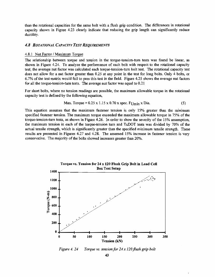
than the rotational capacities for the same bolt with a flush grip condition. The differences in rotational capacity shown in Figure 4.23 clearly indicate that reducing the grip length can significantly reduce ductility.
4.8 ROTATIONAL CAPACITY TEST REQUIREMENTS
4.8.1 Nut Factor I Maximum Torque
The relationship between torque and ten~ion in the torque-tension-tum tests was found be linear, as shown in Figure 4.24. To analyze the performance of each bolt with respect to the rotational capacity test, the average nut factor was calculated each torque-tension-turn bolt test. The rotational capacity test does not allow for a nut factor greater than 0.25 at any point in the test for long bolts. Only 4 bolts, or 6.7% of the test matrix would fail to pass this test in the field. Figure 4.25 shows the average nut factors for all the torque-tension-turn tests. The average nut factor was equal to 0.21
For short bolts, where no tension readings are possible, the maximum allowable torque in the rotational capacity test is defined by the following equation,
Max. Torque = 0.25 x 1.15 x 0. 70 x spec. Fum in x Dia. (5)
This equation assumes that the maximum fastener tension is only 15% greater than the minimum specified fastener tension. The maximum torque exceeded the maximum allowable torque in 75% of the torque-tension-tum tests, as shown in Figure 4.26. In order to show the severity of the 15% assumption, the maximum tension in each of the torque-tension tum and TxDOT tests was divided by 70% of the actual tensile strength, which is significantly greater than the specified minimum tensile strength. These results are presented in Figures 4.27 and 4.28. The assumed 15% increase in fastener tension is very conservative. The majority of the bolts showed increases greater than 20%.
Torque vs. Tension for 24 x 120 Flush Grip Bolt in Load Cell
1400 Box Test Setup
.. 1200
: . ~ .... ..........
1000 -s i 800 ,_,
Q,) :
& 600 .... c:>
fi-; 400
200
0 0 50 100 ISO 200 250 300 350
Tension (k.N)
Figure 4. 24 Torque vs. tension for 24 x 120 flush grip bolt
43

6 0.20 -y
= roo. = 0.15 z ~ e o.1o ~
~ 0.05
0.00
Average Nut Factors in Torque-Tension-Turn Tests
%4 x 70 Flush %4 x 100 3TurM 24 • 100 Flush %4 • 120 3Turns %4 x120 Flush 20 x 50 Flush 20 x 60 Flush 20 x 70 l'lush
Figure4. 25 Average nut factors in torque-tension-turn tests
Figure 4. 26 Maximum torque in test!AASHTO maximum allowable torque
44

:=- 1.45 -c.l)
= 1.40 Cli
"" -00. 1.35 :! ~ = 1.30 Cli ~ iC
1.25 1:--e ....... 1.20 = 0 ·;;
1.15 = Cli ~ -1.10 :a ~
~ 1.05
~ 1.00
Figure 4. 28
:! "'
Max. Tension in Test I (0.7*Bolt Tensile Strength) for Torque-Tension-Turn Tests
Maximum tension in Test/(0. 7*bolt tension strength) for torquetension-turn tests
~ 1.25 -1-----11-
r... e 1.20 +--+---.......
6 1.15 ·;; = Cli ~ 1.10 -rll Cli
~ 1.05 ~
~ 1.00
Figure 4. 27 Maximum tension in Test/(0. 7*bolt tensile strength) for TxDOT tests
45

4.8.2 Ductility
An additional tenet of the rotational capacity test requires that the minimum tension in the fastener must be equal to or greater than 1.15 times the minimum required installation tension at a rotation equal to 2 times the minimum required nut rotation. The testing conditions and equipment used in the TxDOT tests are nearly the same as the conditions for a field rotational capacity test with a bolt calibrator. As a result, the TxDOT test results were used to analyze the behavior of the bolts with respect to the ductility requirements of the rotational capacity test. The use of a bolt calibrator to monitor fastener tension allows the person performing the test to control the snug tension. To take into account the control over the snug tension, the turns in the TxDOT tests were measured from the 10% of minimum specified tensile strength snug condition. Figure 4.29 shows the relationship between the tension at 1 turn with the minimum required installation tension for the TxDOT tests. All values are significantly greater that 1.15. Therefore, the bolts have satisfactory tensions at this point on the tension-tum curve. However, some of the bolts in the solid plate tests were found to have ultimate rotational capacities close to 1 turn (Figure 4.23), which is only twice the specified turn-of-the-nut rotation for 24 mm bolts with lengths greater than 4 times the diameter. The ultimate rotational capacities for bolts tested in the TxDOT Skidmore test setups are shown in Figure 4.30. The 24 mm x 100 mm 3 turn bolts had rotational capacities as low as 1.167 and the lowest rotational capacity for the 24 mm x 120 mm 3 turns bolts was 1.333 turns. For a 1/2 turn installation requirement, these bolts do not have much ductility beyond 2 times the required nut rotation, or 1 turn.
1.750
.-.: 1.500 i ~
f;l;.
c:J 1.250 Q,j
c. 00 • 1.000 t--= ._ ...... c 0.750 :.. = E--..... 0.500 ...... c:o: c .e 0.250 Ill c ~
E--0.000
Figure 4. 29
Tension at 1 Tum I Minimum Specified Fastener Tension for TxDOT Tests
Tension at one turn I minimum specified fastener tension for TxDOTtests
46

~ ... .e ·; ~ 0 .... "' = ... =
Eo-<
2.500
2.250
2.000
1.750
1.500
1.250
1.000
0.750
0.500
0.250
0.000
Turns to Failure for Bolts in TxDOT Tests (Measured from 10% of Spec. Fumm Snug)
Figure 4. 30 Turns to failure for all bolts in TxDOT tests
4.8.3 Rotation Verification Test
In the field, a rotation verification test must be performed in a bolt calibrator to ensure that the specified number of tum tightens the fastener to the proper tension. The rotation verification test requires that the specified turns of the nut produce a fastener tension in the calibrator that is no less than 5 % higher than the minimum specifies fastener tension. The required nut rotations to reach 1.05 x 0.7 x minimum specified tensile strength for those tests that most resembled real field installation conditions, the TxDOT tests, are presented in Figure 4.31.
47

~ = Q ... -= -Q
=: .... = z
Required Nut Rotations to Reach 1.05*0.7*Minimum Specified Tensile Strength for TxDOT Skidmore Tests
0.500 .....--------------------------,
0.333
0.250
0.167
0.083
0.000
Figure 4. 31 Required nut rotations to reach 1.05*0.70*minimum specified tensile strength in TxDOT tests
48

CHAPTERS
RECOMMENDED SPECIFICATION CHANGES
5.1 INTRODUCTION
The results of the A325M metric bolt tests are compared with the AASHTO specifications for the tum-ofthe-nut procedure and rotational capacity test. The results indicate a need to set new installation requirements for the turn-of-the-nut procedure. These recommended changes to the specification are examined with respect to the rotational capacity test and the rotational verification test. A summary of the conclusions and recommended specification alterations is listed in Chapter 6.
5.2 TURN-OF-THE-NUT REQUIREMENTS
The general tension-tum behavior for the metric bolts tested in this research project is depicted in Figure 5.1. The minimum required fastener tension is significantly below the inelastic plateau. The maximum fastener tensions were more than 25% greater than the minimum specified fastener tension (Figures 4.28 and 4.29). The AASHTO Specification assumes only a 15% increase in tension, based on the results presented in the Bolt Guide and in the commentary of the Bolt Specification. The difference in maximum fastener tension is amplified by comparing the turns to reach the minimum required fastener tension with the turns to reach 0.7 x measured bolt tensile strength, as shown in Figure 5.2. The turns required to reach the minimum fastener tension are not large enough to fully yield the bolt, as expected with the turnof-the-nut procedure. Because the minimum fastener tension is on the linear-elastic portion of the tension-tum curve, the force in the bolt is very sensitive to small changes in nut rotation. The ideal turnof-the-nut would result in a bolt elongation that correlates with the inelastic part of the curve, where bolt tension is not sensitive to small variances in nut rotation. In this ideal case, the turn-of-the- Bolt nut requirement would induce a bolt tension Tension that far exceeds the minimum required tension with typical bolts, which have a tensile strength above the specified minimum.
Figure 5.3 shows the range of turns required to reach the minimum specified fastener tension from the least stiff test setup for each length to diameter ratio examined. All turns were measured from a snug tension equal to 10% of the minimum specified tensile strength for each bolt diameter (20.3 kN for the 20 mm bolts and 29.3 kN for the 24 mm bolts). The turn values are indicated with the square symbols and the range is given by the horizontal lines. The current AASHTO turn-
a
b
-- ----r-----,.--- -'/
l.lS*Min. Spec. Tension
a= 0.7*Fult
b = 0.7*F min. ult
Nut Rotation
Figure 5. 1 General tension-turn behavior
49

0.6~---------------------------------------------,
rll
=
0.5
0.4
.~ ..... 0.3 a ~ = 0.2 z
0.1
0
D 0.7 x Min. Spec. Tensile Strength
0. 7 x Actual Bolt Tensile Strength
l4x7l1Fitub l4xlll03Tums l4xlllOI'Iarh l4xl20:1Turm l4xl20FIIuh :IOx!IOflu.. :IOx~Fitub 20x7l1Fiush
Figure 5. 2 Comparison of turns required to reach 0. 7 x min. spec. tensile strength with turns required to reach 0. 7 x actual bolt tensile strength
Turns to Minimum Specified Fastener Tension (from 10% of Minimum Specified Tensile Strength Snug Condition)
0.500 ......-------------------------.,
--; Jili. ai 0.417 c.
00
= i 0.333 i< r--Q
s rll
= ... = Eo-<
0.250
1/2 Tom - 30° Tolerance r---
I! 1/3 Tum- 30" Tolerance ""'Current AASHTO ________ ...J Inch Bolt
1 I I
Requirements
0.167 +---+---+---+---+---+---+---1 2.000
Figure 5. 3
2.500 3.000 3.500 4.000 4.500 5.000 5.500 Length I Diameter
Comparison of turns to minimum specified fastener tension with current AASHTO tum-of-the-nut requirements
50

of-the-nut requirements (using the 300 tolerance) are indicated with a dotted line. The complete nut rotation results were presented in Figures 4.15 through 4.22. For bolts with a length to diameter ratio equal to or less than 4, AASHTO specifies 1/3 tum to reach the required tension. For bolts with a length to diameter ratio greater than 4, AASHTO specifies 1/2 tum to reach the required tension. These AASHTO tum-of-the-nut requirements have positive and negative tolerances of 300. The metric bolt results indicate that l/3 tum will not induce the required tension in all of the bolts with length to diameter ratios less than 4. If the tolerance of 300 is used, none of the shorter bolts would reach the required fastener tension. The bolts with length to diameters ratios greater than 4 reach the minimum specified tension in less turns than the 1/2 tum minus 300 tolerance requirement. However, these results indicate that bolts with higher length to diameter ratios (but still less than the next AASHTO tum-of-the-nut plateau with length to diameter ratios greater than 8) may require more turns than the negative tolerance allows. The data from tests in solid plates, Figure 4.22, show that a rotational factor of safety of at least two is attained with these installation rotations even for bolts with just three threads in the grip. These solid plate data represent the most extreme condition which could be encountered in the field.
New AASHTO tum-of-the-nut requirements for A325M bolts should be set to reflect the tension-tum behavior of these bolts. The specified turns for bolts with length to diameter ratios less than or equal to 4 should be changed from 1/3 tum to 1/2 tum.
5.3 ROTATIONAL CAPACITY TEST
5.3.1 Nut Factor I Maximum Torque
The nut factors calculated for the torque-tension-tum tests (as presented in Figure 4.24) indicate that the maximum allowable nut factor of 0.25 in the rotational capacity test is applicable to metric bolts. Using a maximum nut factor of 0.25 would result in a an acceptance rate greater than 93% for the tested A325M metric bolts.
For short bolts, where no tension readings are possible, the maximum allowable torque in the rotational capacity test is equal to 0.25 x maximum fastener tension x diameter. The maximum fastener tension is assumed to be 15% greater than the minimum specified fastener tension. The minimum specified bolt tensile strength is used instead of the measured bolt tensile strength The maximum test torque results presented in Figure 4.26 demonstrate the severity of the tensile strength assumption. 75% of the metric bolts tests had torque values greater than the maximum allowable value. Figures 4.27 and 4.28 show that the assumed 15% difference in fastener tension is more representative of the increase in fastener tension from 0.7 x measured bolt tensile strength than the increase in fastener tension from 0.7 x minimum specified bolt tensile strength. Therefore, the assumed maximum fastener tension in a short bolt rotational capacity test should be calculated as 1.15 x 0.7 x average bolt tensile strength from mill reports.
5 .3 .2 Ductility
The rotational capacity test requires that the minimum tension in the fastener must be equal to or greater than 1.15 times the minimum required installation tension at a rotation equal to 2 times the AASHTO tum-of-the-nut requirement. For all length to diameter ratios tested in this research, a 1/2 tum nut rotation requirement is recommended. Therefore, at 1 tum, the bolt tension must be 15% greater than the minimum fastener tension.
51
The test conditions and equipment used in the Tx:DOT Skidmore tests best model a field rotational capacity test. The turns to failure in Figures 4.23 and 4.30 show that the metric bolts have sufficient ductility to reach 1 turn from snug in both the solid plate and Tx:DOT Skidmore test setups. In addition, the ratios of fastener tension at 1 turn to the minimum specified fastener tension (Figure 4.29) indicate that all of the metric bolts had tensions greater than 1.15 x minimum specified fastener tension at a nut rotation equal to twice the recommended tum-of-the-nut requirement.
5.4 ROTATION VERIFICATION TEST
The rotation verification test must be performed in a bolt calibrator to ensure that the specified turns of the nut induce the required tension in the fastener. This test requires that the specified number of turns produce a fastener tension in the bolt calibrator that is no less than 5% greater than the minimum specified fastener tension. If 1/2 turn with 300 tolerances is specified for all of the length to diameter ratios tested, the nut rotation results in Figure 4.31 show that some of the 24 mm x 120 mm flush grip bolts in the Tx:DOT tests do not satisfy this requirement. However, if the negative tolerance is eliminated, all the bolts pass the rotation verification test. Therefore, the negative tolerances for turns should be eliminated.
52

CHAPTER6
SUMMARY OF CONCLUSIONS AND RECOMMENDED CHANGES TO THE AASHTO SPECIFICATION
6.1 CONCLUSIONS
The results of 70 torque-tension-tum tests and 79 tension-tum tests on 20 mm and 24 mm diameter A325M metric bolts with two different lubrication and grip conditons in 5 test setups lead to the following conclusions and recommended changes to the AASHTO Bolt Specification.
• The lubricant supplied on the as received fastener was not significantly degraded by the simulated weathering done in the laboratory.
• The inelastic portion of the tension-tum curve was found to be independent of the test setup. The nut rotations in the elastic range for different types of test setup are approximately equal.
• The required turns to reach a specific tension decrease as the stiffness of the test setup increases.
• The ductility of a bolt decreases as the stiffness of test setup increases.
• The grip length is inversely proportional to the rotational stiffness and directly proportional to the required nut rotations to reach a specified fastener tension.
• The ductiliy of a bolt is significantly decreased by reducing the grip length.
• The minimum required fastener tension for overstrength bolts is significantly below the plateau of plastic behavior. The turns required to reach the minimum fastener tension are not large enough to fully yield the bolt, as expected with the AASHTO Tum-of-the-Nut procedure.
• The AASHTO Tum-of-the-Nut requirement of 113 tum for bolts with length to diameters ratios less than 4 is not sufficient to reach the minimum specified fastener tension.
• The assumed 15% increase in fastener tension from the minimum specified tension to the maximum tension in the AASHTO Rotational Capacity Test for short bolts is extremely conservative. As a result, a large number of the bolt tests had torques that exceeded the maximum allowable torque for short bolts.
• Some of the A325M bolts would not pass the rotation verification test if the 30° tum tolerances are taken into account. All bolts would pass the rotation verification test if the negative 30o tolerances are eliminated.
53

6.2 RECOMMENDED CHANGES TO THE AASHTO BOLT SPECIFICATION
• The specified turn-of-the-nut requirement for bolts with length to diameter ratios less than or equal to 4 should be changed from 1/3 turn to 112 turn.
• The negative 30° tolerance for turns should be eliminated for all length to diameter ratios.
• The assumed maximum fastener tension in a short bolt rotational capacity test should be calculated as 1.15*0.7*average bolt tensile strength from mill reports.
54

APPENDIX A
TEST DATA
55

TableA.l Torque-Tension-Turn Test Results for 24 mm Bolts
Grip Length Test Setup Condition N Max. Tension Torque Torque Nul Factor MAx, Torque Turn• Turns I Turns to Faihm!TRotational Sllffnen at 10%: Fumln al44.48 kN lo0.7xFumtn to 0.7xFu from 44.48 kN
(mm) (kN) (N·m) (N-m) (N·m)
Flush 1 46 LC Box Lubricated 1 274J 166 263 0.257 1583 0.319 0.417 1.73 581 202 255 0.206 1304 0.378 0.468 1.83 502 190 287 0.212 1391 0.341 0.423 1.84 569 273 330 0.204 1294 0.342 0.421 1.85 596
300.2 186 343 0.208 1343 0,324 0.420 1.91 612 294.2 192 280 0.212 1296 0,324 0.416 2.00 605
I 00 J3 Turns! 63 I L. C. Box I Lubricated I 317,0 193 274 0.220 1499 0,317 0.390 1.26 615 337. I 183 256 0.205 1437 0.361 0.433 1.33 593 331.3 212 293 0.211 1503 0.332 0.400 U9 613
Weathered I I I 336.7 tn 267 0.202 1460 0.314 0,383 1.21 624 334.0 180 247 0.195 1381 0.358 0.428 1.30 597 327.7 194 298 0.204 1435 0.360 0.433 1.33 593
Flush 1 76 I L. C. Box 1 Lubricatedf-tT- 308.2 213 297 0.207 1377 0.355 0.453 1.69 540 289 0.210 1349 0.386 0.485 1.73 551 298 0.216 1422 0.355 0.447 1.66 560 282 0.200 1311 0.338 0.425 171 580
tn I I I I I r21 l07.if 21if 277 0.21$ 1394 0.370 0.4$4 1.60 569 0\ I J I 302.51 1901 269 0.219 1433 0.334 0.431 1.55 577
'urns I 1$ I L. C. Box 1 Lubricated I I I 34361 1731 262 0.206 1523 0.311 0.387 1.44 613 0.210 1488 0.309 0.383 126 613
uo 628 1.30 599 1.37 624
1.48 624 262 0,209 1482 0.227 0.275 1.47 900 278 0.218 1488 0.226 0.281 1.40 815 265 0.202 1464 0.210 0.262 1.40 932 236 0.201 1475 0.250 0.303 1.46 913 236 0.194 1427 0,242 0.294 1.39 900 228 0.194 1413 0.222 0.272 1.30 939.
FtV.Sil-1 96 I L.C.Box 1 LubrieatedT 1T miT 1siT 239 0.189 1303 0.358 0.441 2.16 573 241 0,209 1459 0.347 0.433 2.20 515
1472 0.326 0.415 2.24 586i 1415 0,348 0.442 2.24 558 1452 0.328 0.400 2.22 591
2.21 566 L. C. • Solid Plate I Lubricated j I 321.1 165 237 0.209 1450 0.205 0.262 2,06 932
2 319.4 163 211 0.202 1405 0.209 0.274 2.28 873 3 320.1 185 269 0.204 1394 0.268 0.328 2.32 959
Weathered I I 31U 205 244 0.204 1405 0.218 0.278 2.15 819 2 312.8 172 217 0.218 1520 0.242 0.309 2.12 802 3 323.7 187 235 0.204 1380 0.248 0.305 2.09 813

Table A.2 Torque- Tension-Turn Test Results for 20 mm Bolts
Length Grip Grip Length Test Setup Condition # Max. Tension Torque Torque Nut Factor Max. Torque Turns Turns Turns to Failure Rotational Stiffness at 10% Fumln at 44.48 kN to 0. 7xF Umln to 0.7xFu from 44.48 kN
(mm) (mm) (kN) (N·m) (N·m) (N-m) (kNffurn)
so Flush 30 Short Grip Skidmore Lubricated I 2!0.0 120 214 0.167 846 0.321 0.366 2.19 426 2 213.6 128 210 0.215 826 0.324 0.367 2.22 432 3 211.8 120 219 0.218 813 0.323 0.363 2.16 437
Weathered I 210.2 108 225 0.218 822 0.340 0.384 2.16 419 2 2015 121 217 0.207 790 0.328 0.374 2.16 427 3 198.9 127 242 0.258 928 0.333 0.390 1.86 414
60 Flush 39 Short Grip Skidmore Lubricated I 216.3 141 250 0.244 906 0.345 0.415 1.89 408 2 222.0 125 225 0.232 908 0.338 0.405 1.73 412 3 212.2 124 237 0.248 895 0.346 0.418 1.84 393
Weathered I 213.0 133 236 0.251 972 0.326 0.398 1.82 423 2 202.3 127 236 0.261 943 0.331 0.402 1.65 421 3 212.9 129 242 0.240 880 0.331 0.403 1.82 417
70 Flush so L. C. Box Lubricated 1 220.1 169 248 0.225 914 0.377 0.483 1.74 425 2 218.3 ISS 247 0.224 894 0.390 0.484 1.76 432 3 212.0 125 219 0.224 858 0.377 0.488 1.76 419
Weathered I 205.6 130 246 0.248 925 0.266 0.354 1.61 508
~ 2 217.6 149 233 0.227 842 0.402 0.570 1.98 376 3 218.1 157 271 0.244 933 0.365 0.465 1.74 428
-

Table A.3 TxDOT Test Results
Dia. Length Grip Grip Ltngth Tt$1 Setup Condition N Tension Turns Tum• Tum• to Failun atJTum to 0.7xFv"11• to l.OSxO. 7xFv.,. from JO,-, Fv...,
(mm) (mm) (mm) kN) (kNffum)
24 70 Flush 46 Skidmore Lubricated I 291.0 0.281 0.297 1.83 2 294.0 0.217 0.293 1.83 3 289.0 0.285 0.301 1.83
Weatheled I 271.0 0.265 0.283 !.67 2 271.0 0.292 0.308 1.67 3 289.0 0.215 0.292 1.83
100 3Tums 63 Skidmore Lubricated I 314.0 0.290 0.304 Ll7 2 294.0 0.308 0.323 1.17 3 311.0 0.299 0.31S 1.33
Wcatheled I 325.0 0.281 ().296 1.17 2 322.0 0.297 0.323 1.33 3 327.0 0.288 o.m 1.33
Flush 76 Skidmore Lubricated I 300.0 0.334 0.352 1.67 2 305.0 0.324 0.345 1.50 3 302.0 O.JSO 0.374 1.67
Weathered I 309.0 0.346 0.370 1.67 2 298.0 0.327 0.350 1.67 3 298.0 0.313 0.329 I. SO
120 3 Turns 75 Skidmore Lubrie:ttcd I 342.0 0.330 0.349 1.33
~ 2 342.0 0.347 0.366 1.33 3 334.0 0.374 0.392 uo
Weathered ~ -·331.0 0.347 0.367 I. SO 2 322.0 0.387 0.405 1.33 3 lli.O 0.361 0.379 1.33
Flush 96 Skidmore Lubricated I 316.0 0.392 0.413 2.33 2 302.0 0.388 GAll 2.33 3 311.0 0.390 0.411 2.50
Wcathen.-d I 305.0 0.406 0.426 1.83 2 316.0 0.379 0.400 2.17 3 311.0 0.399 0.420 2.50
'21) --so ~~flush 30 Short Grip Skidmore lubricated I 200.0 o.28S 0.335 2.33 2 198.0 0.310 0.329 2.17 3 200.0 0.311 0.329 2.17
Weathered I 176.0 0.276 0.335 uo 2 180.0 0.288 0.354 1.67 3 187.0 0.288 0.354 1.83
60 Fhnh 39 Short Grip Skidmore Lubricated I 214.0 0.347 0.371 1.83 2 20S.O 0.320 0.343 1.83 3 209.0 0.341 0.367 1.83
Weathered I 193.0 0.362 0.396 1.61 2 180.0 0.334 0.381 1.33 3 200.0 0.307 0.324 1.67
70 Flush 50 Skidmon: Lubricated 1 218.0 0.254 0.268 1.67 2 216.0 0.292 0.307 1.83 3 218.0 0.273 0.287 1.83
Weathered I 214.0 0.271 0.292 1.83 2 214.0 0.283 0.299 1.83 3 229.0 0.284 0.300 1.67

Ul \C
Dia.
(mm)
24
20
Length
(mm)
70
120
50
70
Grip
3 Turns
Flush
3Tums
Flush
Flush
3Tums
Flush
--
Table A.4 Solid Plate Test Results
Grip Length Condition # Turns to Failure Rotational Stiffness 1 from 44.48 kN
(mm) (kNffurn) 32 Lubricated I 1.10 2124
2 1.12 2144 3 1.10 2256
46 Lubricated I 1.64 1711' 2 1.65 1960 3 1.65 2122
75 Lubricated 1 1.13 1343 2 1.12 1324 3 1.11 1439
96 Lubricated 1 1.85 1468 2 1.84 1180 3 1.74 1222
30 Lubricated 1 1.61 2399 2 1.60 2498 3 1.61 2572
37 Lubricated 1 1.07 1844 2 1.06 2150 3 1.11 2111
50 Lubricated 1 1.76 1912 2 1.77 2025 3 1.88 1967

60

REFERENCES
1. American National Standards Institute "Metric Heavy Hex Structural Bolts,"ANSI B18.2.3.7M-1979.
2. American National Standards Institute "Metric Heavy Hex Nuts," ANSI B18.2.4.6M-1979.
3. American Society of Testing Materials "High-Strength Bolts for Structural Steel Joints (Metric)," ASTM A325M-93.
4. American Society of Testing Materials "Carbon and Alloy Steel Nuts (Metric)," ASTM A563M-93.
5. Belford, R. B. "The First Report on the New Heavy Structural Bolt Fasteners," Industrial Fastener Institute, Nos. 2 and 3, Vol. 15, Fall-Winter, 1960.
6. Bendigo, R. A. and Rumpf, J. L. "Static Tension Tests on Long Bolted Joints," Fritz Laboratory Report No. 271.8, Lehigh University, Feb 1960.
7. Chesson, E. and Munse, W. H. "Studies of the Behavior of High-Strength Bolts and Bolted Joints," Engineering Experiment Station Bulletin 469, University oflllinois, Oct. 1964.
8. Eaves, L. D. "Influence of Thread Lubrication on the Behavior of High Strength Bolts," Ferguson Structural Engineering Laboratory Thesis No. 78-3, University of Texas, Austin, July 1978.
9. Fisher, J. W. "Field Installation of High Strength Bolts in North America and Japan," IABSE Survey S-8n9, Zurich, Switzerland.
10. Frank, K. H. and Yura, J. A. "An Experimental Study of Bolted Shear Connections," FHWAIR.D-81-148, Federal Highway Administration, Washington, D.C., Dec 1981.
11. Yura, J. A., K. H. Frank, and D. Polyzois "High Strength Bolts for Bridges", FHW AIR.D-87/088, Federal Highway Administration, Washington, D.C., Dec 1987.
12. "Sets of High Strength Hexagon Bolt, Hexagon Nut, and Plain Washers for Friction Grip Joints", JlS B 1186, Japanese Standards Association, J 1 S Handbook Fasteners and Screw Threads. 1986.
13. Standard Specifications for Highway Bridges, American Association of State Highway and Transportation Officials, 15th Edition, 1992.
61


![[TECHNICAL DATA]STRENGTH OF BOLTS, SCREW PLUGS, AND](https://static.fdocuments.net/doc/165x107/623c878951866371cb1baad5/technical-datastrength-of-bolts-screw-plugs-and.jpg)


