
Thermodynamics of Void Fraction in Saturated Flow Boilingfuster/ASME-J.HeatTransfer 05.pdf ·...
18
18/10/05 Collado 1 Thermodynamics of Void Fraction in Saturated Flow Boiling Francisco J. Collado*, Carlos Monné*, Antonio Pascau†, Daniel Fuster†, Andrés Medrano* *Dpto. Ingeniería Mecánica, †Dpto. Ciencia Mat.&Fluidos, CPS-B Univ. Zaragoza, Zaragoza, 50018, Spain Phone: +34 976 762551, Fax: +34 976 762616, E-mail: [email protected] Abstract Recently, Collado [6] suggested calculating void fraction, an essential element in thermal-hydraulics, working with the ‘thermodynamic’ quality instead of the usual ‘flow’ quality. The ‘thermodynamic’ quality is a state variable, which has a direct relation with the actual vapor volumetric fraction, or void fraction, through phase densities. This approach provides a procedure for predicting void fraction, if values of ‘thermodynamic’ quality are available. However, the standard heat balance is usually stated as a function of the ‘flow’ quality. Therefore, we should search a new heat balance between the mixture enthalpy, based on ‘thermodynamic’ quality, and the absorbed heat. This paper presents the results of such analysis based on the accurate measurements of the outlet void fraction measured during the Cambridge project by Knights [4] in the sixties for saturated flow boiling. In the 286 tests analyzed, the pressure and mass fluxes range from 1.72 MPa to 14.48 MPa and from 561.4 to 1833.33 kg m -2 s -1 , respectively. As main result, we find that the slip ratio would close this new thermodynamic heat balance. This has allowed the accurate calculation of void fraction from this balance, provided we can predict the slip ratio. Finally, the strong connection of this new thermodynamic heat balance with the standard one through the slip ratio is highlighted. Keywords: Saturated flow boiling, void fraction, thermodynamic quality, slip ratio 1. Introduction A large number of correlations [1-2] have been proposed for the evaluation of the cross-sectional average volumetric fraction or void fraction of vapor bubbles, α, which is of considerable interest to nuclear and fossil power industries because void fraction significantly affects neutron absorption, heat transfer and pressure drop [1-6]. Many of them are expressed in terms of the phase velocity ratio or slip ratio, S, which is defined as the cross-sectional area mean vapor velocity, u G (m/s), divided by the cross-sectional area mean liquid velocity, u L (m/s). Collier [1], reviewing the better-known correlations for α, concludes that for the most accurate ones the standard deviation of error on the mean density is about 30 %. However, depending on the data bank used for the
Transcript of Thermodynamics of Void Fraction in Saturated Flow Boilingfuster/ASME-J.HeatTransfer 05.pdf ·...
18/10/05 Collado 1
Thermodynamics of Void Fraction in Saturated Flow Boiling
Francisco J. Collado*, Carlos Monné*, Antonio Pascau†, Daniel Fuster†, Andrés Medrano*
*Dpto. Ingeniería Mecánica, †Dpto. Ciencia Mat.&Fluidos, CPS-B Univ. Zaragoza, Zaragoza, 50018, Spain
Phone: +34 976 762551, Fax: +34 976 762616, E-mail: [email protected]
Abstract
Recently, Collado [6] suggested calculating void fraction, an essential element in thermal-hydraulics, working
with the ‘thermodynamic’ quality instead of the usual ‘flow’ quality. The ‘thermodynamic’ quality is a state
variable, which has a direct relation with the actual vapor volumetric fraction, or void fraction, through phase
densities. This approach provides a procedure for predicting void fraction, if values of ‘thermodynamic’ quality
are available. However, the standard heat balance is usually stated as a function of the ‘flow’ quality. Therefore,
we should search a new heat balance between the mixture enthalpy, based on ‘thermodynamic’ quality, and the
absorbed heat. This paper presents the results of such analysis based on the accurate measurements of the outlet
void fraction measured during the Cambridge project by Knights [4] in the sixties for saturated flow boiling. In
the 286 tests analyzed, the pressure and mass fluxes range from 1.72 MPa to 14.48 MPa and from 561.4 to
1833.33 kg m-2 s-1, respectively. As main result, we find that the slip ratio would close this new thermodynamic
heat balance. This has allowed the accurate calculation of void fraction from this balance, provided we can
predict the slip ratio. Finally, the strong connection of this new thermodynamic heat balance with the standard
one through the slip ratio is highlighted.
Keywords: Saturated flow boiling, void fraction, thermodynamic quality, slip ratio
1. Introduction
A large number of correlations [1-2] have been proposed for the evaluation of the cross-sectional average
volumetric fraction or void fraction of vapor bubbles, α, which is of considerable interest to nuclear and fossil
power industries because void fraction significantly affects neutron absorption, heat transfer and pressure drop
[1-6]. Many of them are expressed in terms of the phase velocity ratio or slip ratio, S, which is defined as the
cross-sectional area mean vapor velocity, uG (m/s), divided by the cross-sectional area mean liquid velocity, uL
(m/s). Collier [1], reviewing the better-known correlations for α, concludes that for the most accurate ones the
standard deviation of error on the mean density is about 30 %. However, depending on the data bank used for the
Void fraction Prediction in Saturated Flow Boiling
18/10/05 Collado 2
comparison, these best void fraction correlations, which also include the calculation of the slip ratio, may show a
standard deviation for S ranging from 30% to 80%.
In this work, which is focused on saturated flow boiling, we suggest using the ‘thermodynamic’ quality to
calculate the void fraction, instead of the ‘flow’ quality used in classic treatments.
The standard energy balance [1-6] for saturated flow boiling is, assuming negligible kinetic and gravity
terms,
€
q = xohG + 1− xo( )hL' flow' mixtureenthalpy1 2 4 4 4 3 4 4 4
− hL ⇒ xo = q hG − hL( ) = q ΔhLG , (1)
where q denotes the total absorbed heat along the duct per unit mass inlet liquid (in short, heat per unit mass) in
(kJ/kg), subscript G and L denotes saturated vapor and saturated liquid, respectively, h is enthalpy (kJ/kg), and xo
is the outlet standard ‘flow’ quality. The further assumptions that only liquid enters into the duct exactly at
saturation conditions [4-6], and that the pressure drop along the duct is negligible so that hL and hG are constant
saturation values, are included in Eq. (1).
The classic definition of x as a mass flow rate ratio clearly shows that it includes the slip ratio, S,
€
x =WG WG +WL( ) = uGρGAcα uGρGAcα + uLρLAc 1−α( )[ ] = ρGαS ρGαS + ρL 1−α( )[ ] , (2)
where W denotes mass flow rate (kg/s), ρ is mass density (kg/m3), Ac is the cross-sectional area of the duct (m2),
and the standard definitions of mass flow rate and the slip ratio,
€
S = uG uL , are used. For the sake of
convenience, void fraction can be derived from Eq. (2),
€
α = 1 1+ S 1− x( ) x[ ] ρG ρL( ){ } = xβ xβ + S 1− x( )[ ] , (3)
where we have followed [5] to denote the liquid-vapor mass density ratio as β. Furthermore, the slip ratio can be
expressed in function of the void fraction and the ‘flow’ quality using the standard mass flow rates, see page 7 in
[2],
€
S = uG uL = WGρL 1−α( )Ac[ ] WLρGαAc( ) = xρL 1−α( )[ ] 1− x( )ρGα[ ] = β x 1−α( )[ ] 1− x( )α[ ] . (4)
The key point of this work is to use the well-known ‘thermodynamic’ quality,
€
xth , classically defined as
[3],
€
xth = ρGα ρm , (5)
where ρm denotes the standard mixture density of the vapor-liquid mixture (kg/m3).
There is a direct connection between void fraction and ‘thermodynamic’ quality, xth, through phase
densities, which is derived from the strict definitions of α and the mixture density. So following [2-4], the void
Void fraction Prediction in Saturated Flow Boiling
18/10/05 Collado 3
fraction is strictly defined as, α=Area occupied by steam/Total cross-sectional area of flow=dAG/dA, which is
directly measured by gamma- or X-ray attenuation.
Furthermore, for an element of area dA, the mixture density is given by [2-4]
€
ρm = ρLdAL + ρGdAG( ) dA = 1−α( )ρL +αρG . (6)
Now the inverse of the mixture density is the mixture specific volume, vm. Then, if we write vm as a
combination of the saturated liquid and vapor specific volumes weighted by the actual vapor mass fraction, x’,
€
vm = x' vG + (1− x' )vL = x' ρG + (1− x' ) ρL = 1 ρm ⇒ x'= xth =αρG ρm . (7)
Therefore, it is evident that the actual vapor mass fraction, which corresponds with the actual (directly
measured) vapor void fraction, is the ‘thermodynamic’ quality, xth, and not the ‘flow’ quality.
Finally, the derivation of α from Eq. (5), also including Eq. (6), is immediate,
€
α = xthβ xthβ + 1− xth( )[ ] . (8)
The obvious advantage of Eq. (8) on Eq. (3) is that S does not appear. However, as we will show later,
really this is not true because we need to predict S for the closure of the new thermodynamic relation found.
Now the question is how heat transfer can be related to the mixture enthalpy increment,
€
Δhm , which here
will be based on ‘thermodynamic’ quality,
€
xth ,
€
hm = xthhG + 1− xth( )hL ⇒ Δhm = hm,o − hL = xth,oΔhLG . (9)
Notice the difference of this ‘thermodynamic’ mixture enthalpy from the ‘flow’ mixture enthalpy in Eq. (1).
In this work, we will compare this ‘thermodynamic’ mixture enthalpy increment of the fluid passing
through the heated duct versus the heat input per unit mass using the careful void fraction data of Knigths [4]
taken during the Cambridge Project for vertical and horizontal saturated flow boiling. For the data set analyzed,
the main result is that the slip ratio should be explicitly used for the closure of this new energy balance.
Furthermore, based on the same data set, a new and improved slip ratio correlation is presented. The void
fraction values calculated through the new heat relation and the new slip ratio correlation compare quite well
with the measured ones. Finally, the equivalence of the standard heat balance with the new thermal relation
through the slip ratio is highlighted.
2. Flow Boiling Measurements in the Cambridge Project
In his dissertation [4], Knights presented experimental measurements of the void fraction made at the outlet
of a water boiling flow in 1.5 inch (0.0381 m) bore 24 feet (7.32 m) long pipe in vertical (upwards flow) and
horizontal position at several inlet pressures of industrial interest. The operating pressures for the main test series
were 1.72 MPa (250 psia), 4.14 MPa (600 psia), 8.62 MPa (1250 psia) and 14.48 MPa (2100 psia). The closed

Void fraction Prediction in Saturated Flow Boiling
18/10/05 Collado 4
loop rig was operated at pressures up to 22.1 MPa (3206 psia), and electrical heating was employed to ensure
ease of control and uniformity of heating of the test section. The outlet ‘flow’ quality, Eq. (1), was less than 0.2
in the 286 tests analyzed here. Circulation was assisted by a centrifugal pump, and the mass flux range from
561.4 to 1833.3 kg m-2 s -1. The inlet pressure was accurate to better than ± 1% at all operating pressures. The
overall accuracy of the flow rate measurements, through a sharp edged orifice plate, could be expected to lie
within ± 4%. The electrical power supplied to the pipe was measured with Wattmeter, and the heat losses were
normally less than 10% of the total power input, and these were measured to ±5%. The outlet void fraction data
were taken through chordal scanning by collimated gamma-ray beam, with scintillation counter as detector.
Thus, the dispersion pattern was investigated. For horizontal flow boiling, the factor 1.014 converted the centre-
line scanning void fraction to the mean void fraction on the section within 1.5 % of difference. For vertical
(upwards) flow boiling, it was also found that the factor 0.8 could convert quite well the centre-line chordal
scanning of the void fraction to the mean void fraction. The maximum deviation from the factor of 0.8 was
11.5% and the mean deviation 4.3%.
Figure 1 shows the measured outlet mean void fraction versus the outlet ‘flow’ quality, last one calculated
from Eq. (1), using the measured effective power input, the inlet mass flow rate, and the inlet pressure.
3. New Thermodynamic Heat Balance
Figure 2 compares the thermodynamic mixture enthalpy increment in (kJ/kg), Eq. (9), versus the measured
absorbed heat per unit mass inlet water, also in (kJ/kg). The outlet thermodynamic quality, included in Eq. (9),
has been calculated using the measured outlet void fraction and inlet pressure, see Eqs.(5)-(6). The disagreement
between enthalpy increment and heat is rather strong and cannot be justified by measurement uncertainties. In
vertical tests, the specific potential energy, gL, has also been included, L being the height of the pipe, 24 feet,
i.e., gL= 0.071 kJ/kg. Now the question is which parameter could balance this thermodynamic relation.
We have found, see Fig. 3, that the slip ratio, S, from Eq. (4), which includes xo and αo data, would balance
quite well this thermodynamic comparison, suggesting a new heat balance for saturated flow boiling.
From the basic equations stated before, it is easy to expand the q/Δhm ratio to check whether the relation
suggested by Fig.3 is a trivial one or not,
€
q Δhm + gL( )[ ] = x xth = x ρm ρGα( )[ ] = x + βx 1−α( ) α . (10)
Equation (10) should be compared with the classic expression of S, Eq. (4). Only at very low values of
‘flow’ quality, x, Eq. (10) could reduce to Eq. (4). Furthermore, Fig. 3 has been also verified in [6] using Thom
Void fraction Prediction in Saturated Flow Boiling
18/10/05 Collado 5
data [5] for 1 inch (0.0254 m) bore horizontal pipe, in which more than half of ‘flow’ qualities were higher than
0.1 and the higher one was near 0.8. Therefore, Fig. 3 would suggest that,
€
q Δhm + gL( )[ ] ≈ S . (11)
A possible justification of Eq. (11), already suggested elsewhere [6], could be that the time scales of the
phases are different because we are treating two different velocities (that of the liquid and the vapor) in the same
length (the same control volume), and this physical fact should be included in the heat balance in some manner.
So taking into account that the heat input per unit mass inlet water is q [kJ/kg]= Q[kW]/WL,i[kg/s], and assuming
that heat enters into the control volume exclusively through vapor bubbles (vapor time scale) that condense in
the saturated liquid, Eq. (11) would mean that the slip ratio S could act as a time scale factor conversion between
the liquid (WL,i) and vapor (Q i.e., bubbles) phases.
Finally, in comparing Eqs. (1), (10) and (11), we could say that, for saturated flow, the standard heat balance
based on ‘flow’ quality and the one proposed here and based on ‘thermodynamic’ quality, are indeed equivalent,
the difference between them merely being a time scale factor conversion i.e., the slip ratio S.
4. New Slip Ratio Correlation and Void Fraction Prediction
For horizontal flow boiling and based on previous work [6], Fig. 4 shows the new fitting equations
proposed for the slip ratio, S. The water inlet velocity,
€
uL,i (m/s) multiplied by S is clearly a linear function
of
€
uL,i , which varies with the inlet pressure and the heat flux. It has also been checked at the other pressures that
the straight lines, function of heat flux, are practically parallel. Therefore, it has been suggested a parametric
fitting such as
1,0,10, SuuSuSuSu iLiLiL +=⇒+= , (12)
where u0 is the point of crossing with the ordinate axis and S1 is the slope of the straight lines, see Fig. 4.
Logically, S1 would be the same for all the parallel lines at the same pressure and u0 will change with heat flux.
As best fitting, we have found a potential curve to represent S1 in function of pressure (in MPa), see Fig.5.
Furthermore, a linear relation fits well u0 (in m/s) as a function of heat flux (kW/m2) for the different pressures,
see Fig. 6.
As an approximation to vertical flow, see Fig. 7, we could say that the straight lines converge in some point
below 0.1, =iLSu . After checking the lines at different pressures and for the sake of generality, we have chosen a
fitting such as Eq. (12), but now u0 is fixed at 0.77 m/s for all the fluxes (straight lines) and pressures. With this
restriction, we have fitted the lines to find the corresponding S1. Figure 8 shows its behavior: at low heat fluxes,
Void fraction Prediction in Saturated Flow Boiling
18/10/05 Collado 6
it seems that S1 varies more or less linearly with heat flux, but after some value which depends on pressure, S1
remains constant.
Using the fittings for S in horizontal and vertical flow, Figs. 5-6 and Fig. 8, respectively, we can calculate
the thermodynamic mixture enthalpy increment from the new heat balance, Eq. (11). So from a known inlet
pressure, we can derive the outlet thermodynamic quality using Eq. (9). Finally, from Eq. (8), we obtain the
predicted void fraction for horizontal flow, see Fig. 9, with a mean absolute error of 0.0019, and the predicted
void fraction for vertical flow, see Fig. 10, with a mean absolute error of -0.0054.
Alternatively, following the classical procedure, we could directly insert the calculated slip ratio into Eq.
(3) for obtaining the void fraction. In this case, the mean absolute error in the prediction of void fraction for
horizontal flow is -0.0014, and that of vertical one -0.0085.
5. Conclusions
The main result of this paper is reflected in Fig.3, which clearly shows that, for vertical and horizontal
saturated flow boiling, the slip ratio closes the heat balance between the thermodynamic mixture enthalpy
increment (calculated with the measured void fraction and the densities and enthalpies of the two phases) and the
heat input per unit mass inlet water.
The validity of the suggested new heat balance for horizontal and vertical saturated flow boiling, Eq. (11), is
limited to the range of the ‘flow’ quality measured in [4] i.e., x≤0.2. However, other verification of this new heat
balance, using Thom data [5] for horizontal saturated flow boiling, was presented elsewhere [6], in which the
‘flow’ quality was higher, x≤0.8.
The introduction of the slip ratio in the new heat balance could be justified because we consider two
different velocities (two phases) in the same length (the same control volume), which would imply different time
scales for the phases. This should be included in the heat balance in some manner. Thus, the slip ratio would act
as a time scale factor between the phases.
New slip ratio fittings, function of the inlet pressure and the absorbed heat flux, have also been proposed.
However, more data is needed to obtain full correlations. Also the behavior of the straight line fittings for
vertical flow (convergent) is rather different from horizontal flow (parallel). With the new fittings of S, the
prediction of the mean outlet void fraction through the new suggested procedure is quite acceptable for saturated
flow. On the other hand, the void fraction prediction through the standard equations, with the new S fittings, is of
the same order of accuracy.
Void fraction Prediction in Saturated Flow Boiling
18/10/05 Collado 7
Finally we could say that, for saturated flow, the standard heat balance based on the ‘flow’ quality and the
new proposed here using the thermodynamic quality are indeed equivalent, the difference between them merely
being a time scale factor i.e., the slip ratio S.
Acknowledgements
The authors are indebted to Dr. Geoffrey A. Knights AM. FTS., Retired Deputy Chancellor of Monash
University, for his kind permission to photocopy his dissertation.
The authors also want to thank to the Spanish Minister of Education and Science (MEC) the funding of this
research through the special action ENE2004-0279-E and the research project DPI2005-08654-C04-04.
References
[1] Collier, J. G., 1991, Nuclear Steam Generators and Waste Heat Boilers, in Boilers, Evaporators and
Condensers, S. Kakaç, ed., John Wiley and Sons, New York, Chap. 9.
[2] Collier, J. G., and Thome, J. R., 1994, Convective Boiling and Condensation, third ed., Oxford University
Press, Oxford, UK.
[3] Lahey, R. T. Jr., and Moody, F. J., 1979, The Thermal Hydraulics of a Boiling Water Nuclear Reactor,
American Nuclear Society, La Grange Park, IL.
[4] Knights, G. A., 1960, “A Study of Two-phase Pressure Drop and Density Determination in a High-Pressure
Steam-water Circuit,” Ph.D. thesis, Cambridge University Engineering Lab., Cambridge, UK.
[5] Thom, J. R. S., 1959, “A Study of Pressure Drop and Allied Phenomena During the Flow of a Fluid in the
Presence and Absence of Vaporization,” Ph.D. thesis, Cambridge University Engineering Lab., Cambridge, UK.
[6] Collado, F. J., 2001, “Mass Quality, Void Fraction and Slip Ratio in Bulk Flow Boiling,” Proc. IMECE 2001,
Symposium on Fluid Physics and Heat Transfer for Macro- and Micro-Scale Gas-Liquid and Phase-Change
Flows, HTD, New York.
Void fraction Prediction in Saturated Flow Boiling
18/10/05 Collado 8
List of captions
Fig.1. Outlet void fraction vs. outlet ‘flow’ quality
Fig.2. Thermodynamic heat balance discrepancy
Fig.3. New thermodynamic heat balance, which explicitly includes S, for saturated flow boiling
Fig. 4. S correlation for horizontal flow at 600 psia (4.14 MPa)
Fig. 5. Slope of the S correlation vs. pressure for horizontal flow
Fig.6. Point of crossing with the ordenate axis of the S correlation vs. heat flux for horizontal flow
Fig.7. S correlation for vertical flow at 600 psia (4.14 MPa)
Fig.8. Slope of the S correlation vs. heat flux at different pressures for vertical flow
Fig.9. Void fraction prediction in horizontal flow with Eq. (8)
Fig.10. Void fraction prediction in vertical flow with Eq. (8)
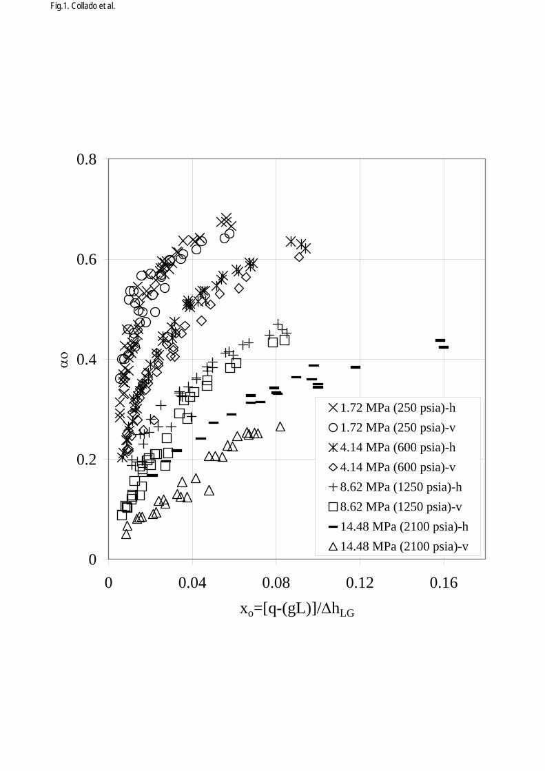
Fig.1. Collado et al.
0
0.2
0.4
0.6
0.8
0 0.04 0.08 0.12 0.16xo=[q-(gL)]/ΔhLG
αο
1.72 MPa (250 psia)-h1.72 MPa (250 psia)-v4.14 MPa (600 psia)-h4.14 MPa (600 psia)-v8.62 MPa (1250 psia)-h8.62 MPa (1250 psia)-v14.48 MPa (2100 psia)-h14.48 MPa (2100 psia)-v
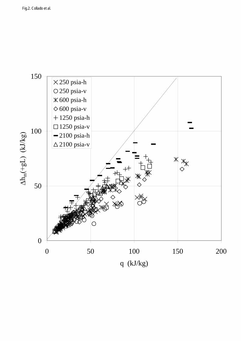
Fig.2. Collado et al.
0
50
100
150
0 50 100 150 200q (kJ/kg)
Δm
250 psia-h250 psia-v600 psia-h600 psia-v1250 psia-h1250 psia-v2100 psia-h2100 psia-v
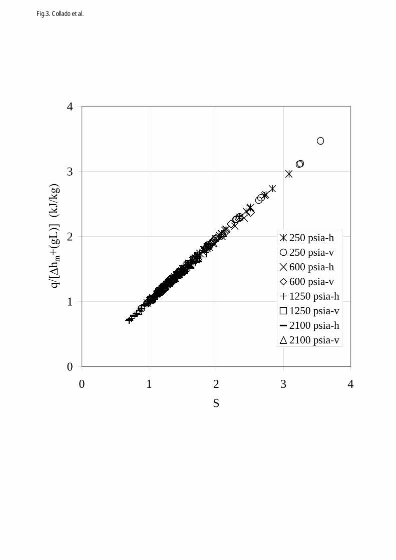
Fig.3. Collado et al.
0
1
2
3
4
0 1 2 3 4S
Δm
250 psia-h250 psia-v600 psia-h600 psia-v1250 psia-h1250 psia-v2100 psia-h2100 psia-v
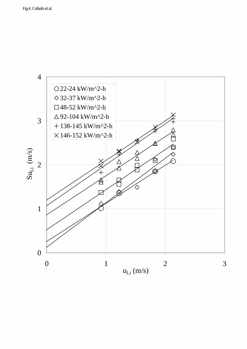
Fig.4. Collado et al.
0
1
2
3
4
0 1 2 3uLi (m/s)
Li
22-24 kW/m^2-h32-37 kW/m^2-h48-52 kW/m^2-h92-104 kW/m^2-h138-145 kW/m^2-h146-152 kW/m^2-h
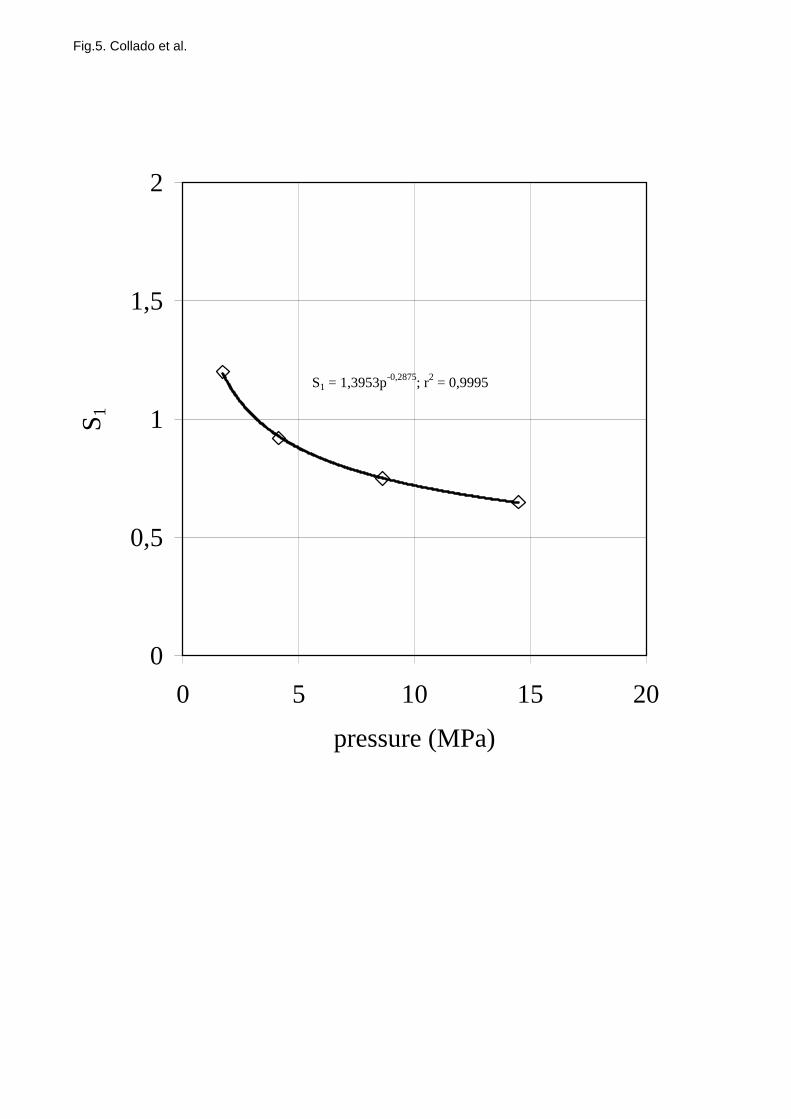
Fig.5. Collado et al.
S1 = 1,3953p-0,2875; r2 = 0,9995
0
0,5
1
1,5
2
0 5 10 15 20
pressure (MPa)
S 1
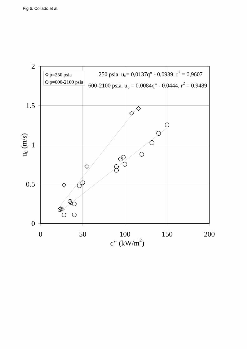
Fig.6. Collado et al.
250 psia. u0= 0,0137q" - 0,0939; r2 = 0,9607
600-2100 psia. u0 = 0.0084q" - 0.0444. r2 = 0.9489
0
0.5
1
1.5
2
0 50 100 150 200q" (kW/m2)
u 0 (m
/s)
p=250 psiap=600-2100 psia
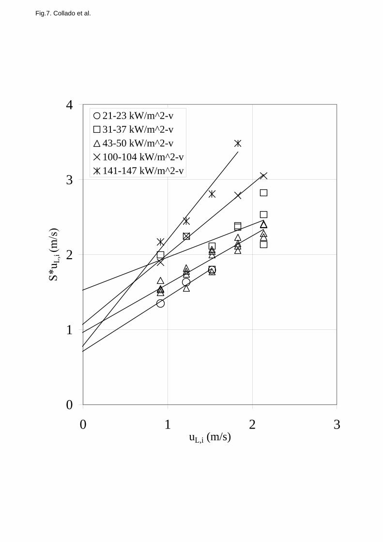
Fig.7. Collado et al.
0
1
2
3
4
0 1 2 3uL,i (m/s)
L,i
21-23 kW/m^2-v31-37 kW/m^2-v43-50 kW/m^2-v100-104 kW/m^2-v141-147 kW/m^2-v
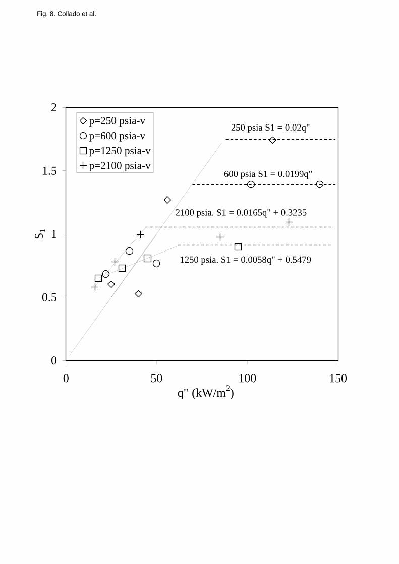
Fig. 8. Collado et al.
600 psia S1 = 0.0199q"
250 psia S1 = 0.02q"
1250 psia. S1 = 0.0058q" + 0.5479
2100 psia. S1 = 0.0165q" + 0.3235
0
0.5
1
1.5
2
0 50 100 150q" (kW/m2)
S 1
p=250 psia-vp=600 psia-vp=1250 psia-vp=2100 psia-v
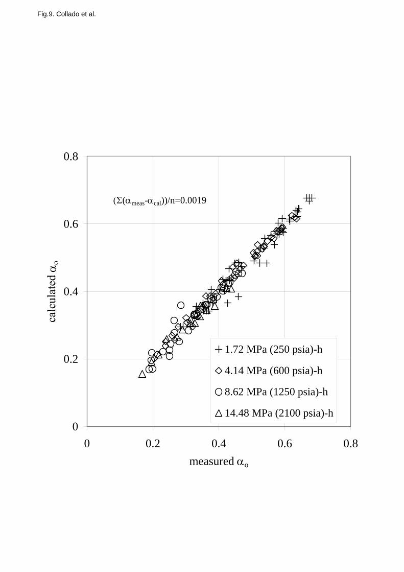
Fig.9. Collado et al.
0
0.2
0.4
0.6
0.8
0 0.2 0.4 0.6 0.8measured αo
αο
1.72 MPa (250 psia)-h
4.14 MPa (600 psia)-h
8.62 MPa (1250 psia)-h
14.48 MPa (2100 psia)-h
(Σ(αmeas-αcal))/n=0.0019
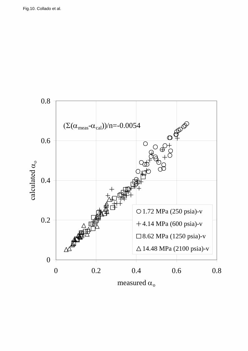
Fig.10. Collado et al.
0
0.2
0.4
0.6
0.8
0 0.2 0.4 0.6 0.8measured αo
αο
1.72 MPa (250 psia)-v
4.14 MPa (600 psia)-v
8.62 MPa (1250 psia)-v
14.48 MPa (2100 psia)-v
(Σ(αmeas-αcal))/n=-0.0054


