Thermo-Mechanical Fatigue Life Assessment of a Diesel ... · impose many restrictions on the design...
11
256 International Journal of Automotive Engineering Vol. 1, Number 4, October 2011 1. INTRODUCTION In recent years, increasing needs for higher power density, low emission and low fuel consumption impose many restrictions on the design process of diesel engine components. Therefore, the design and analysis methods of diesel engines have become substantially more complicated. Piston is one of the most challenging components in diesel engine which is subjected to high thermal and mechanical loads. Large temperature difference between piston crown and cooling galleries induces significant thermal load in piston. Besides, the firing pressure, piston acceleration and piston skirt side force can develop cyclic mechanical stresses which are superimposed on former thermal stresses. Therefore, thermo- mechanical fatigue is the main cause of failure in diesel engine piston. The term “thermo-mechanical fatigue” (TMF) is used to describe fatigue in a component which is experiencing temperature and mechanical strain changes simultaneously [1].Under thermo-mechanical fatigue loading, total damage may occur due to fatigue, environmental degradation (oxidation) and creep mechanisms [2]. Thermo-mechanical fatigue life assessment methods can be classified as empirical methods, fracture mechanics theories, continuum mechanical models and models based on microstructure [3]. Empirical models correlate the number of cycles to failure to parameters of the hysteresis loop, e.g. stress, strain, plastic strain, etc. Diesel engine piston is subjected to high temperature and multiaxial mechanical loading. Thermo-mechanical fatigue is the most important cause of failure in diesel engine piston, so its thermo- mechanical fatigue life estimation has to be done precisely. Piston’s life assessment procedure must be comprehensive and suitable for complex geometry and non-proportional multiaxial loading conditions. In this paper a precise procedure for the thermo- mechanical fatigue life assessment of a diesel engine piston is proposed. This procedure is outlined as follows: • Determination of cyclic stress-strain distribution in piston under its loading conditions. • Calculation of low cycle fatigue life of piston using appropriate theories. • Calculation of high cycle fatigue safety factors. A detailed thermo-mechanical stress analysis of piston has been performed. The thermal boundary conditions have been applied to finite element model of the piston. Temperature distribution of piston, Thermo-Mechanical Fatigue Life Assessment of a Diesel Engine Piston M. R. Ayatollahi * , F. Mohammadi and H. R. Chamani 1 Professor, 2 MSc student, 3 PhD student, Faculty of Mechanical engineering, Iran University of Science and Technology. Tehran, Iran. * [email protected] Abstract In this study, a precise finite element analysis has been carried out on a diesel engine piston, in order to attain its high cycle fatigue (HCF) safety factor and low cycle fatigue (LCF) life. In order to calculate the HCF safety factor, a macro has been developed using ANSYS Parametric Design Language (APDL). The relative stress gradient parameter is used in order to perceive stress concentration and notch effect. In high cycle fatigue assessment, the effect of mean stress is considered using Haigh diagram. Different LCF life assessment methods have been used to investigate LCF life of piston and their results are compared to each other. The diesel engine piston is subjected to non-proportional multiaxial loading. The non-proportional loading leads to an additional cyclic hardening in the material. Critical plane LCF theories are appropriate for consideration of the additional cyclic hardening effect on the LCF life reduction of the piston. Keywords: Thermo-mechanical fatigue; Diesel engine piston; Critical plane; Low cycle fatigue; High cycle fatigue.
Transcript of Thermo-Mechanical Fatigue Life Assessment of a Diesel ... · impose many restrictions on the design...

256
International Journal of Automotive Engineering Vol. 1, Number 4, October 2011
1. INTRODUCTION
In recent years, increasing needs for higher power
density, low emission and low fuel consumption
impose many restrictions on the design process of
diesel engine components. Therefore, the design and
analysis methods of diesel engines have become
substantially more complicated. Piston is one of the
most challenging components in diesel engine which
is subjected to high thermal and mechanical loads.
Large temperature difference between piston crown
and cooling galleries induces significant thermal load
in piston. Besides, the firing pressure, piston
acceleration and piston skirt side force can develop
cyclic mechanical stresses which are superimposed on
former thermal stresses. Therefore, thermo-
mechanical fatigue is the main cause of failure in
diesel engine piston.
The term “thermo-mechanical fatigue” (TMF) is
used to describe fatigue in a component which is
experiencing temperature and mechanical strain
changes simultaneously [1].Under thermo-mechanical
fatigue loading, total damage may occur due to
fatigue, environmental degradation (oxidation) and
creep mechanisms [2]. Thermo-mechanical fatigue
life assessment methods can be classified as empirical
methods, fracture mechanics theories, continuum
mechanical models and models based on
microstructure [3]. Empirical models correlate the
number of cycles to failure to parameters of the
hysteresis loop, e.g. stress, strain, plastic strain, etc.
Diesel engine piston is subjected to high
temperature and multiaxial mechanical loading.
Thermo-mechanical fatigue is the most important
cause of failure in diesel engine piston, so its thermo-
mechanical fatigue life estimation has to be done
precisely. Piston’s life assessment procedure must be
comprehensive and suitable for complex geometry
and non-proportional multiaxial loading conditions.
In this paper a precise procedure for the thermo-
mechanical fatigue life assessment of a diesel engine
piston is proposed. This procedure is outlined as
follows:
• Determination of cyclic stress-strain
distribution in piston under its loading
conditions.
• Calculation of low cycle fatigue life of piston
using appropriate theories.
• Calculation of high cycle fatigue safety factors.
A detailed thermo-mechanical stress analysis of
piston has been performed. The thermal boundary
conditions have been applied to finite element model
of the piston. Temperature distribution of piston,
Thermo-Mechanical Fatigue Life Assessment of a DieselEngine Piston
M. R. Ayatollahi*, F. Mohammadi and H. R. Chamani
1 Professor, 2MSc student, 3PhD student, Faculty of Mechanical engineering, Iran University of Science and Technology. Tehran,
Iran.
Abstract
In this study, a precise finite element analysis has been carried out on a diesel engine piston, in order to attain its high
cycle fatigue (HCF) safety factor and low cycle fatigue (LCF) life. In order to calculate the HCF safety factor, a macro
has been developed using ANSYS Parametric Design Language (APDL). The relative stress gradient parameter is used
in order to perceive stress concentration and notch effect. In high cycle fatigue assessment, the effect of mean stress is
considered using Haigh diagram. Different LCF life assessment methods have been used to investigate LCF life of
piston and their results are compared to each other. The diesel engine piston is subjected to non-proportional multiaxial
loading. The non-proportional loading leads to an additional cyclic hardening in the material. Critical plane LCF
theories are appropriate for consideration of the additional cyclic hardening effect on the LCF life reduction of the
piston.
Keywords: Thermo-mechanical fatigue; Diesel engine piston; Critical plane; Low cycle fatigue; High cycle fatigue.

which has been obtained from the thermal analysis,
has been applied as a volumetric load in structural
analysis. In order to correctly model the material
nonlinearity, a kinematic hardening model is used to
simulate material behaviour. Different load steps of
structural analysis consist of thermal loading, inertia
loading, combustion pressure and piston skirt side
force. The high cycle fatigue safety factors are
calculated considering the mean stress effect by using
Haigh diagram. Notch effect has been considered by
using the relative stress gradient parameter. The
critical plane low cycle fatigue (LCF) life assessment
methods, appropriate for consideration of additional
cycle hardening due to non-proportional loading, has
been used to estimate LCF life of piston.
2. MATERIAL
Aluminum silicon alloys (predominantly eutectic)
are widely employed to produce pistons due to their
low density, high thermal conductivity, good
castability and workability, good machinability and
sound high temperature strength [4].
In this study the piston material is AlSi12CuMgNi
cast alloy with eutectic microstructure. As all the
engine components around the combustion chamber
experience significantly high temperatures and
temperature gradients, temperature dependent
material properties have to be used. Some temperature
dependent properties of piston material are shown in
Table 1.
According to thermal analysis results maximum
piston temperature reaches 374 °C, therefore cyclic
behaviour of material is considered at 20, 150, 250 and
350 °C. The equation of uniaxial cyclic stress–strain
curve is described as follows:
(1)
where E is the Young’s modulus, is the stress
amplitude, is the strain amplitude, is the cyclic
strength coefficient and is the cyclic strain
hardening exponent. The values of and at
different temperatures are listed in Table 2.
Fatigue limit and low cycle fatigue constants of
AlSi12CuMgNi cast alloy at different temperatures
are listed in Tables 3 and 4, respectively.
3. FINITE ELEMENT ANALYSIS
In order to perform thermo-mechanical fatigue
analysis of the piston, one must have the piston cyclic
stress-strain distribution in its loading conditions. Due
to the complex geometry and loading of piston,
analytical methods can’t be applied to obtain its cyclic
stress-strain distribution. Therefore, finite element
(FE) analysis is applied to obtain the local stress–stain
responses by simulating multiaxial loading conditions
for piston.
The values of thermal stresses in the piston are
n�K �n�
K �a�
a�
� �naaa KE ����1
// ���
257
International Journal of Automotive Engineering Vol. 1, Number 4, October 2011
M. R. Ayatollahi, F. Mohammadi and H. R. Chamani
Elastic modulus
(GPa)
Tensile strength (GPa)
ConductivityW/mK
TempC
80 0.2155 20 77 0.18156 150 72 0.09159 250 69 0.035164 350
Table 1. Temperature dependent properties of
AlSi12CuMgNi [4].
cyclic strain hardening exponentn�
cyclic strength coefficient)N/mm( 2K �
TempC
0.11402200.113701500.112412500.11104350
Table 2. Values of and at different temperatures [5].
Fatiguelimit
N/mm2
TempC
8120741504725020350
Table 3. Fatigue limit of AlSi12CuMgNi at different
temperatures [4].
Fatigue ductilityexponent
c
Fatigue ductilitycoefficient
f��
Fatigue strengthexponent
b
Fatigue strengthcoefficient
f� �
TempC
-0.490.013-0.053921120-0.490.013-0.0539194150-0.490.0347-0.0539118250-0.490.13-0.053944.7350
Table 4. Low cycle fatigue constants of AlSi12CuMgNi at
different temperatures [5].

258
International Journal of Automotive Engineering Vol. 1, Number 4, October 2011
large enough and they may lead to low cycle fatigue
failure. Besides, it may introduce high mean stresses
and promote high cycle fatigue failure even in the
regions with insignificant amplitude of cyclic
mechanical loadings. Therefore, the temperature
distribution and temperature gradient in the piston
should be attained very accurately. The piston
temperature is usually considered to be independent of
the operating states and remains constant during a
working cycle [6]. Since the time response of piston
material to the variation of boundary conditions in a
firing cycle is very slow, a steady state thermal
analysis has been done considering the typical values
of temperatures and heat transfer coefficients at piston
boundary surfaces during one firing cycle. The
boundary conditions considered for thermal analysis
of the piston assembly can be summarized as:
• Temperature and heat transfer coefficient of hot
combustion gases at piston crown.
• Temperature and heat transfer coefficient of
cooling oil in piston cooling galleries.
• Heat transfer coefficient of piston and oil ring
contact surfaces.
• Heat transfer coefficient of piston and
compression rings contact surfaces.
• Heat transfer coefficient of piston and piston pin
contact surfaces.
• Heat transfer coefficient at piston skirt.
Assuming a steady state thermal case, Fig. 1 shows
some of the thermal boundary conditions of piston
including the heat transfer coefficients and
temperatures for the piston at different positions.
These thermal boundary conditions were obtained
from literature [7, 8] and modified based on brake
mean effective pressure of current engine. Average
temperature and heat transfer coefficient of hot
combustion gases are obtained from one-dimensional
thermodynamic analysis of engine cycle using Gt-
Power software.
Fig. 2 illustrates the finite element model used for
thermal analysis. This model includes piston and
piston pin which is in contact with piston. The
temperature distribution of the piston is shown in Fig.
3. Table 5 shows a comparison between the
temperatures obtained from the present thermal
analysis in some points of piston (shown in Fig. 3) and
those given by the piston manufacturing company
(MAHLE), which have been validated experimentally
[9]. Good agreement can be seen between these two
sets of results.
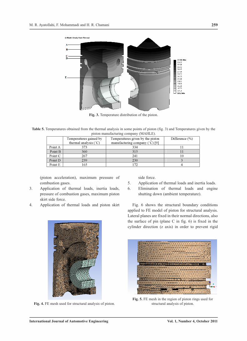
In order to attain the magnitude of stresses and
stress gradients in the piston more precisely, the FE
mesh has been refined in the contact and stress
concentration regions. Figs. 4 and 5 show the FE mesh
used for structural analysis of piston. In this analysis
multilinear kinematic hardening model is used to deal
with material nonlinearity. The following load cases
are defined to simulate different stages of start-stop
cycle:
1. Application of thermal loads (temperature).
2. Application of thermal loads, inertia loads
Thermo-mechanical fatigue life assessment of a diesel engine piston
Fig. 1. Thermal boundary conditions used in the Fig. 2. FE mesh used for thermal analysis of piston.
(piston acceleration), maximum pressure of
combustion gases.
3. Application of thermal loads, inertia loads,
pressure of combustion gases, maximum piston
skirt side force.
4. Application of thermal loads and piston skirt
side force.
5. Application of thermal loads and inertia loads.
6. Elimination of thermal loads and engine
shutting down (ambient temperature).
Fig. 6 shows the structural boundary conditions
applied to FE model of piston for structural analysis.
Lateral planes are fixed in their normal directions, also
the surface of pin (plane C in fig. 6) is fixed in the
cylinder direction (z axis) in order to prevent rigid
259
International Journal of Automotive Engineering Vol. 1, Number 4, October 2011
M. R. Ayatollahi, F. Mohammadi and H. R. Chamani
Fig. 4. FE mesh used for structural analysis of piston.
Fig. 5. FE mesh in the region of piston rings used for
structural analysis of piston.
Fig. 3. Temperature distribution of the piston.
Difference (%)Temperatures given by the pistonmanufacturing company (˚C) [9]
Temperatures gained bythermal analysis (˚C)
11334373Point A11315360Point B10241267Point C3230239Point D4172165Point E
Table 5. Temperatures obtained from the thermal analysis in some points of piston (fig. 3) and Temperatures given by the
piston manufacturing company (MAHLE).

260
International Journal of Automotive Engineering Vol. 1, Number 4, October 2011
body motion. Further, the connection between the
piston and piston pin was changed from the default
“bonded” to “frictional” with a very low friction
coefficient.
Fig. 7 shows the distribution of equivalent Von-
Mises stresses in the piston after application of
thermal loads, inertia loads, pressure of combustion
gases and maximum piston skirt side force. In the
lower regions of piston skirt, close to oil inlet
drillings, due to the reduction of piston wall thickness
and stress concentration effect, the induced stresses
are high. As can be seen in Fig. 7, the regions around
the oil inlet hole and the contact regions of piston and
piston pin are subjected to severe stresses. Table 6
gives the values of equivalent von-Mises stresses of
critical points A and B, shown in Fig.7, at different
steps of structural loading.
4. HIGH CYCLE FATIGUE LIFE ASSESSMENT
High cycle fatigue generally contains elastic cyclic
behaviour, high frequency, low strain amplitude and
large number of cycles to failure [10]. Constant life
diagrams graphically represent the safe regime of
constant amplitude loading for a given specified life
and have been widely used for high cycle fatigue life
estimation [11]. The Haigh diagram is a constant-life
diagram that plots alternating stress versus mean stress
and it is based upon Goodman equation [12]:
Thermo-mechanical fatigue life assessment of a diesel engine piston
Fig. 6. Structural boundary conditions applied to FE model
for structural analysis.
Fig. 7. Distribution of equivalent von Mises stresses in the piston due to thermal loads, inertia loads, pressure of combustion
gases and maximum piston skirt side force.
Load step 5 Load step 4Load step 3 Load step 2 Load step 1Load step
point 6.1e64.8e79.4e76.3e61.3e7A4.2e73.8e75.1e71.9e73.4e7B
Table 6. Values of equivalent Von-Mises stresses of critical points A and B, shown in fig.7, at load steps 1 to 5.

261
International Journal of Automotive Engineering Vol. 1, Number 4, October 2011
(2)
where alt is the alternating stress, mean is the
mean stress, R=-1 is the stress amplitude at fully
reversed loading, and UTS is the ultimate tensile
strength. The Haigh diagram can be used in order to
consider the effect of mean stress in high cycle fatigue
life estimation. Fig. 8 illustrates a scheme of the mean
stress effect diagram or Haigh diagram.
By using Haigh diagram and calculating the
equation of its lines and also having the magnitudes of
the equivalent nominal stress amplitude and
equivalent nominal mean stress, Sqa and Sqm , the high
cycle fatigue safety factor of piston can be easily
attained at each node of finite element model. Fig. 9
shows the Haigh diagram of piston material based on
and FKM guideline [5].
The equivalent nominal stress amplitude, Sqa, has
been computed according to the following relation:
(3)
where Sa1, Sa2 and Sa3 are principal alternating
nominal stresses with Sa1>Sa2>Sa3.
The equivalent nominal mean stress, Sqm, has been
computed as followes:
(4)
where Sm1, Sm2 and Sm3 are principal mean nominal
stresses.
5. NOTCH EFFECT CONSIDERATION
When finite element method (FEM) is applied to
assess HCF safety factor of notched components
under dynamic loadings, it must be considered that
FEM stress results give no indication of the type of the
loading. When fatigue life estimation is going to be
done with reference to tensile fatigue properties,
inaccurate dimensioning may occur for the regions
where bending/torsion stress is dominant. Moreover,
real mechanical components generally contain many
small fillets and blends, which can act as stress risers.
Structural FE analysis gives notch a stress in these
regions but this stress can’t be used in the fatigue life
calculations and must be modified somehow in order
to get closer to the real amount experienced in the
notch region.
Eichlseder [13] proposed a method for HCF safety
factor assessment considering the load type and notch
effect by using relative stress gradient parameter. The
relation between fatigue limit and stress gradient can
be determined as follows:
231
232
221 )()()(
21
mmmmmmqm SSSSSSS ���
231
232
221 )()()(
21
aaaaaaqa SSSSSSS ���
��
��
)1(1UTS
meanRalt �
��� � �
M. R. Ayatollahi, F. Mohammadi and H. R. Chamani
Fig. 8. Schematic of Haigh diagram.
Fig. 9. Haigh diagram of piston material [11].
262
International Journal of Automotive Engineering Vol. 1, Number 4, October 2011
(5)
where tf and bf are fatigue limit in tension and
bending respectively. b is the diameter of the specimen
from which the bending fatigue limit is obtained. KD
is a material parameter in the range of 0.5 to 0.8 for
engineering metals. For piston material KD is
considered as 0.6 approximately. Relative stress
gradient is defined as:
(6)
where max is the notch root stress calculated by
FEM. Therefore, in high cycle fatigue life prediction
of components, it is needed to calculate the relative
stress gradient at critical nodes of finite element
model. Then, all of the material constants (fatigue
limit, ultimate and yield stresses in tension and
compression) must be corrected by using the stress
gradient coefficient:
(7)
6. HCF LIFE ASSESSMENT IMPLEMENTATION
AND RESULTS
In order to calculate the HCF safety factors, a
macro has been developed using ANSYS Parametric
Design Language (APDL). Haigh diagram is modified
according to the magnitude of stress gradient, nodal
temperature and modification factors at each node.
The mean and alternating stresses resulted from cyclic
loads are computed at each node. Then, HCF safety
factor for each node is attained.
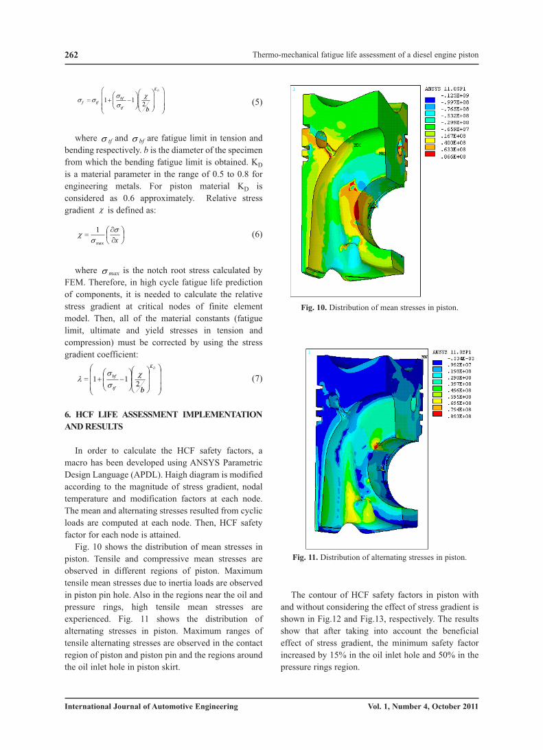
Fig. 10 shows the distribution of mean stresses in
piston. Tensile and compressive mean stresses are
observed in different regions of piston. Maximum
tensile mean stresses due to inertia loads are observed
in piston pin hole. Also in the regions near the oil and
pressure rings, high tensile mean stresses are
experienced. Fig. 11 shows the distribution of
alternating stresses in piston. Maximum ranges of
tensile alternating stresses are observed in the contact
region of piston and piston pin and the regions around
the oil inlet hole in piston skirt.
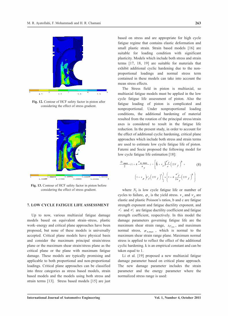
The contour of HCF safety factors in piston with
and without considering the effect of stress gradient is
shown in Fig.12 and Fig.13, respectively. The results
show that after taking into account the beneficial
effect of stress gradient, the minimum safety factor
increased by 15% in the oil inlet hole and 50% in the
pressure rings region.
���
�
���
�
�
��
�
��
�
�
���
���
���
DK
tf
bf
b211 �
��
�
�
��
�����
�x�
��
max
1
�
��
1 1 2
DK
bff tf
tf b
� �� ��
� � � � �� �� � � �� �� �� �� �� �� �
Thermo-mechanical fatigue life assessment of a diesel engine piston
Fig. 10. Distribution of mean stresses in piston.
Fig. 11. Distribution of alternating stresses in piston.
7. LOW CYCLE FATIGUE LIFE ASSESSMENT
Up to now, various multiaxial fatigue damage
models based on equivalent strain–stress, plastic
work–energy and critical plane approaches have been
proposed, but none of these models is universally
accepted. Critical plane models have physical basis
and consider the maximum principal strain/stress
plane or the maximum shear strain/stress plane as the
critical plane or the plane with maximum fatigue
damage. These models are typically promising and
applicable to both proportional and non-proportional
loadings. Critical plane approaches can be classified
into three categories as stress based models, strain
based models and the models using both stress and
strain terms [13]. Stress based models [15] are just
based on stress and are appropriate for high cycle
fatigue regime that contains elastic deformation and
small plastic strain. Strain based models [16] are
suitable for loading condition with significant
plasticity. Models which include both stress and strain
terms [17, 18, 19] are suitable for materials that
exhibit additional cyclic hardening due to the non-
proportional loadings and normal stress term
contained in these models can take into account the
mean stress effects.
The Stress field in piston is multiaxial, so
multiaxial fatigue models must be applied in the low
cycle fatigue life assessment of piston. Also the
fatigue loading of piston is complicated and
nonproportional. Under nonproportional loading
conditions, the additional hardening of material
resulted from the rotation of the principal stress/strain
axes is considered to result in the fatigue life
reduction. In the present study, in order to account for
the effect of additional cyclic hardening, critical plane
approaches which include both stress and strain terms
are used to estimate low cycle fatigue life of piston.
Fatemi and Socie proposed the following model for
low cycle fatigue life estimation [18]:
(8)
where Nf is low cycle fatigue life or number of
cycles to failure, y is the yield stress. e and p are
elastic and plastic Poisson’s ratios, b and c are fatigue
strength exponent and fatigue ductility exponent, and
and are fatigue ductility coefficient and fatigue
strength coefficient, respectively. In this model the
damage parameters governing fatigue life are the
maximum shear strain range, , and maximum
normal stress, n,max , which is normal to the
maximum shear strain range plane. Maximum normal
stress is applied to reflect the effect of the additional
cyclic hardening. k is an empirical constant and can be
taken equal to 1.
Li et al. [19] proposed a new multiaxial fatigue
damage parameter based on critical plane approach.
The new damage parameter includes the strain
parameter and the energy parameter where the
normalized stress range is used:
�max�
f� �f� �
���
���
�
���
�
��� �
��
���
��
�
��� �
����
� �
�� �
bfN
y
fkc
fNfp 22
121
� ���
�
���
� �
��
����
bfN
ef
e)y
n,k( 21max12max
263
International Journal of Automotive Engineering Vol. 1, Number 4, October 2011
M. R. Ayatollahi, F. Mohammadi and H. R. Chamani
Fig. 12. Contour of HCF safety factor in piston after
considering the effect of stress gradient.
Fig. 13. Contour of HCF safety factor in piston before
considering the effect of stress gradient.

264
International Journal of Automotive Engineering Vol. 1, Number 4, October 2011
(9)
This model uses maximum shear strain range,
, and range of normal stress, , in the damage
parameter and is suitable for proportional and
nonproportional loading conditions.
Recently, Li et al. [20] modified Shang–Wang
fatigue damage parameter. The modified damage
parameter combines maximum shear strain range with
normal strain range on the critical plane, and a new
stress-correlated factor, , is introduced to take
account of the additional cyclic hardening:
(10)
where is the maximum shear strain range.
is the range of normal stress. This model can be
applied under both proportional and nonproportional
loading conditions.
8. DETERMINATION OF CRITICAL PLANE
Most fatigue cracks initiate in the maximum shear
direction because the slip systems which align in these
directions experience the largest amount of
deformation. But cracks also initiate at a slower rate in
the directions with less degrees of shear [21].
Therefore, it can be assumed that maximum fatigue
damage occurs at the plane of maximum shear strain
amplitude. This plane is called the critical plane. In
order to determine the maximum shear strain range
plane or critical plane, one must take the following
steps [22]:
1. Determine the stress and strain tensors at all
nodes of FE model by carrying out an elasto-
plastic finite element analysis for the
component.
2. Consider a candidate plane at the target node
(the node which its low cycle fatigue life is
going to be calculated) defined by angles and
(Fig. 14).
3. Calculate the stress and strain tensors on the
candidate plane.
4. Calculate the shear strain range acting on the
candidate plane.
5. Solve for Steps 3 and 4 for all planes in order to
find the maximum shear strain range planes and
their locations.
6. Calculate the normal strain ranges acting on the
maximum shear strain range planes.
7. Compare the values of the normal strain range
acting on the planes of maximum shear strain to
determine the location of critical plane.
9. LCF LIFE ASSESSMENT IMPLEMENTATION
AND RESULTS
In order to calculate LCF life of piston, a macro has
been written using ANSYS Parametric Design
Language (APDL). By using the stress-strain cycle at
each node and according to critical plane approach,
LCF life of piston has been calculated at each node.
The algorithm of the developed macro is outlined as
follows:
1. Reading the data and temperature dependent
material properties at each note.
2. Determination of loading cycles.
3. Selection of elements and nodes at which the
low cycle fatigue life calculations is going to be
done (the piston surface nodes must be
selected).
4. Reading the information of selected nodes such
as node number, node coordinate and etc.
5. Reading the stress analysis results at selected
nodes (according to the applied LCF life model
the needed information such as stresses, strains
must be read and saved in array parameters).
� �crcr �� ,
��
n�max�
� � � �� � � � � � cbf
y
ffcf
fynbf
y
f NNNE
����
����
�� 22
35.02/11
2 22
������
��
� �� � � �bffeyn
ny
n NE
���
����
���
�
��
23
2/11)
21(
3
2
222
max �����
���
���
���
� �
y
n
��
21
n�max�
� �� � � � � � cbf
y
ffcf
fyn NNE
����
��� 22
5.02/11������
� �� � � � � � bf
y
fbf
feyn
y
n NE
NE
��
���
�
� 22
2/11)
21(
22
2max
������
���
Thermo-mechanical fatigue life assessment of a diesel engine piston
Fig. 14. The strains acting on the candidate plane at the
target node [14].

6. Finding critical plane at each node.
7. Calculation of damage parameter at critical
plane.
8. Calculation of LCF life according to the applied
model.
The LCF life contour of piston using Li (Eqs. 9 and
10) model is shown in Fig. 15. Number of LCF life
cycles calculated by Fatemi - Socie (Eq. 8) and Li
(Eqs. 9 and 10) models at critical point A (fig. 15), are
27000, 22000 and 21000 cycles, respectively. The
estimated LCF lives resulted from these models are
very close to each other. The regions around the oil
inlet hole in piston skirt are the critical regions from
the LCF life point of view.
10. CONCLUSIONS
In this study, a detailed thermo-mechanical stress
analysis has been conducted on a diesel engine piston.
Temperature distribution has been obtained from
thermal analysis. In order to attain HCF safety factor, a
macro has been developed using ANSYS Parametric
Design Language (APDL). Then a Haigh diagram is
established for each node based on the calculated stress
gradient and nodal temperature. In order to account for
the effect of additional cyclic hardening, critical plane
approaches which include both stress and strain terms
are used to estimate low cycle fatigue life of piston. The
plane experiencing the maximum shear strain
amplitude is considered as the critical plane.
The results showed that the regions around piston
oil inlet hole and the piston and piston pin contact
region are the most critical regions, mainly due to high
mean and alternating stresses caused by cyclic loads.
After considering the stress gradient effects, the HCF
safety factor improved by 15% in the oil inlet hole and
50% in the pressure rings region. The regions around
the oil inlet hole in piston skirt are the critical regions
from the LCF life point of view.
REFERENCES
[1] Asm Metals Handbook Volume 19 – Fatigue
and Fracture.
[2] Gocmez, T., Awarke, A., Pischinger, S., 2010,
"A New Low Cycle Fatigue Criterion For
Isothermal And Out-Of-Phase
Thermomechanical Loading", Int. J. Fatigue,
32, 769-779.
[3] Minichmayr, R., Riedler, M., Winter, G.,
Leitner, H., Eichlseder, W., 2008, "Thermo-
Mechanical Fatigue Life Assessment Of
Aluminium Components Using The Damage
Rate Model Of Sehitoglu", Int. J. Fatigue, 30,
298–304.
[4] K. Mollenhauer, H. Tschoeke, Handbook of
Diesel Engines, Springer Heidelberg Dordrecht
London New York.
[5] FKM guideline "Numerical Strength Analyses
for Machine Components in Steel, Cast Iron and
Aluminum Materials", 4th Edition, 2002.
[6] P. Gudimetal, C.V. Gopinath, 2009, "Finite
Element Analysis of Reverse Engineered
Internal Combustion Engine Piston ",
AIJSTPME, 2(4), 85-92.
[7] J. Pan, R. Nigro, E. Matsuo, 2005, "3-D
Modeling Of Heat Transfer In Diesel Engine
Piston Cooling Galleries", SAE International.
[8] V.P. Singth, P.C. Upadhyay, N.K. Samria, 1986,
"Some Heat Transfer Studies On A Diesel
Engine Piston", lnt. J. Heat Mass Transfer, 5,
812-814.
[9] MAHLE technical report, Projekt 6500-01595-
01, Nr. PDE08-0070-65.
[10] Nicholas, T., 2006, "High Cycle Fatigue, A
Mechanics of Materials Perspective", 1st
edition, Elsevier.
[11] Sendeckyj G.P., 2001, "Constant life diagrams
— a historical review", International Journal of
Fatigue, 23, 347–353.
265
International Journal of Automotive Engineering Vol. 1, Number 4, October 2011
M. R. Ayatollahi, F. Mohammadi and H. R. Chamani
Fig. 15. Contour of LCF life of piston calculated by Li
model (Eq. 10).

266
International Journal of Automotive Engineering Vol. 1, Number 4, October 2011
[12] Lanning, D. B., Nicholas, T., 2007, "Constant-
life diagram modified for notch plasticity". Int.
J. of Fatigue, 29, 2163–2169.
[13] Eichlseder, w., 2002, "Fatigue analysis by local
stress concept based on finite element results". J
Computers and Structures, 80, 2109–2113.
[14] Li, J., Zhang, Ping, Z., Sun, Q., Li, Ch. W.,
2011, "Multiaxial fatigue life prediction for
various metallic materials based on the critical
plane approach", International Journal of
Fatigue, 33, 90–101.
[15] Susmel, L., 2011, "On The Overall Accuracy Of
The Modified Wöhler Curve Method In Estimating
High-Cycle Multi axial Fatigue Strength", Frattura
Ed Integrità Strutturale, 16, 5-17;
[16] Borodii, M.V., Adamchuk, M.P., 2009, "Life
assessment for metallic materials with the use
of the strain criterion for low cycle fatigue",
International Journal of Fatigue, 31,
1579–1587.
[17] Varvani-Farahani, A., Kodric, T., Ghahramani,
A., 2005, "A method of fatigue life prediction in
notched and un-notched components", Journal
of Materials Processing Technology, 169,
94–102.
[18] Fatemi, A., Socie, D. F., 1988, "A critical plane
to multiaxial fatigue damage including out-of-
phase loading", Fatigue Fract Eng Mater Struct,
11, 149-165.
[19]. Li, J., Zhang, Z. P., Sun, Q., Li C. W., Qiao, Y.
J., 2009, "A new multiaxial fatigue damage
model for various metallic materials under the
combination of tension and torsion loadings". I.
J. Fatigue, 31, 776–781.
[20] Li, J., Zhang, Z. P., Sun, Q., Li C. W., Qiao, Y.
J., 2010, "A modification of Shang–Wang
fatigue damage parameter to account for
additional hardening". Int. J. Fatigue, 32,
1675–1682.
[21] Susmel, L., Atzori, B., Meneghetti, G., Taylor,
D., 2011, "Notch And Mean Stress Effect In
Fatigue As Phenomena Of Elasto-Plastic
Inherent Multiaxiality". Engineering Fracture
Mechanics, Article in Press.
Nomenclature
b Fatigue strength exponent
c Fatigue ductility exponent
E Young’s modulus
Kt Stress concentration factor
Nf Number of cycles to failure
Fatigue ductility coefficient
Maximum principal strain amplitude
i principal stress (i=1,2,3)
fb Bending fatigue limit
ft Tension fatigue limit
Fatigue strength coefficient
max Maximum normal stress
ft Shear fatigue limit
Relative stress gradient
e Elastic Poisson’s ratio
p Plastic Poisson’s ratio���
�f� �
���
a�f� �
Thermo-mechanical fatigue life assessment of a diesel engine piston