fatigue life prediction of thermo-mechanically loaded engine ...

International Journal of Engineering Research & Science (IJOER) ISSN: [2395-6992] [Vol-2, Issue-2, February- 2016]
Page | 144
Thermo-mechanical fatigue behavior of a copper-alumina metal
matrix composite with interpenetrating network structure A.Reeb
1*, S.Dietrich
2, V. Walter
3, P.Pinter
4, K.A. Weidenmann
5, A. Wanner
6
Institute of Applied Materials (IAM-WK), Karlsruhe Institute of Technology, Germany
Abstract—
The properties of interpenetrating metal-ceramic composites (IPC) may be designed following application requirements.
High thermal conductivity combined with low thermal expansion, as well as high stiffness and high strength can be achieved.
Such composites may be adequate materials to meet the requirements of thermally stressed components like heat sinks. For
this purpose an interpenetrating copper-matrix composite was fabricated by squeeze-cast infiltration of porous alumina
preforms. In this work a first approach into characterizing the Out-of-phase-TMF (OOP-TMF) behavior of such a composite
is presented. For that purpose the composite is initially characterized by microstructural investigations, which showed a
mostly homogenous distribution of metallic and ceramic phase, with randomly distributed coarse agglomerates of alumina.
The OOP-TMF experiments were realized via inductive heating of the specimen and were conducted with maximum
temperatures between 250 and 400 °C. The temperature- lifetime correlation from these experiments is presented and the
cyclic deformation behavior was analyzed. A linear correlation between maximum temperature and specimen lifetime was
found. Lifetime of nonreinforced copper was found to exceed the lifetime of the composite and was attributed to inner stress
concentration due to mismatch of thermal expansion coefficients between copper and alumina and coarse alumina phases.
Additional fractographic analyses revealed a crack initiation in surface-near areas and mostly with involvement of coarse
alumina agglomerates.
Keywords—Alumina preform, cyclic deformation behavior, MMC, Squeeze Casting, TMF
I. INTRODUCTION
Copper offers high corrosion resistance, easy processing and is used for electrical and electronic components especially due
to its high thermal conductivity [1]. Thus it is one of the most common materials used for heat conductors and heat sinks.
Unfortunately, the use of copper at elevated temperatures is restricted because of its high thermal expansion and its limited
mechanical properties [2]. More sophisticated materials for dissipation of resulting heat are required in consequence of the
densification of circuits in electronic components. For reasons of reliability, a high degree of adaptation of the heat sink
material’s thermal expansion to the semiconductor material is necessary. Therefore, copper matrix composites (Cu-MMCs)
are applied in components e.g. heat sinks under high material stress. In these composites, the high thermal conductivity of
copper is combined with the low thermal expansion of a second component, which can additionally act as a reinforcing phase
and improve mechanical properties. When it comes to interpenetrated network structures, the ceramic phase can be
responsible for stiffness, whereas the metal phase retains some plasticity and, especially in the case of copper, offers high
thermal and electrical conductivity and therefore makes it interesting for designing composites adapted for heat sink
applications where high mechanical stresses arise. While aluminum based metal matrix composites (IPC) are often
manufactured by squeeze casting [3-5], metals with considerably higher melting temperatures, like copper, are commonly
processed by gas pressure infiltration [6,7], but can be also processed via squeeze casting [8,9]. This offers the benefit of a
fine microstructure and increased strength [10]. The lifetimes observed in stress-controlled low-cycle fatigue (LCF) and
high-cycle fatigue HCF experiments can be improved in comparison with the unreinforced metal by introducing ceramic
phases into a ductile metallic matrix [11]. In strain-controlled isothermal fatigue experiments however it was shown by [12]
and [13] that the fatigue limit decreases with increasing volume fraction of ceramic particles. In components such as heat
sinks, the stress arising in the component is caused by thermal cycling and temperature gradients. Simplifying TMF schemes
can be used for modeling such conditions. Usually the real loading conditions are modeled by either, so called in-phase (IP)
TMF-conditions, where the maximum and minimum loads occur simultaneously with maximum and minimum temperature,
or out-of-phase (OOP) TMF conditions, where maximum loads occurs at the minimum temperatures. Previous testing of
MMCs reinforced with fibers showed that OOP TMF is dominated by matrix stresses, whereas IP TMF is dominated by
maximum stress in the fiber [14-16]. [17] investigated the thermo-mechanical fatigue behavior of a particle-reinforced
aluminum alloy (EN AW-6061) under OOP TMF conditions, and determined a cyclic softening and compared to the

International Journal of Engineering Research & Science (IJOER) ISSN: [2395-6992] [Vol-2, Issue-2, February- 2016]
Page | 145
unreinforced matrix a lower fatigue life. The thermo-mechanical fatigue behavior of MMCs and in particular of IPC has
hardly been topic of research up to now. [18] however investigated IPCs with aluminum matrix and alumina reinforcement.
A decreased thermo-mechanical fatigue life at high temperatures was observed for the composite compared with the matrix
material, however at lower temperatures and thus smaller plastic strain amplitudes the fatigue life of the composite exceeds
the fatigue limit of the matrix material. In this work the thermo-mechanical fatigue behavior of a copper-alumina composite
with an interpenetrating network structure was investigated at different maximum temperatures. Lifetime behavior, as well as
cyclic deformation behavior is described and complemented with fracture surface investigations. Main objective was to get a
first insight in the lifetime and deformation behavior for this novel material class under application-near loading conditions.
II. MATERIALS AND SPECIMEN GEOMETRY
The matrix material used for manufacturing the MMC by squeeze casting was pure copper and is specified regarding its
chemical composition in Table 1; while the reinforcing ceramic structure was alumina. The copper used was of OF-quality,
which means high quality, non-deoxidized, oxygen-free copper suitable for electronic devices because of its high purity and
conductivity.
TABLE 1
MEASURED CHEMICAL ANALYSIS OF COPPER USED FOR INFILTRATION IN WT.-PPM
Pb Bi As Sb Sn Zn Mn Cr Co Cd Fe Ni Ag S Se Te O
Copper <1 <0.5 1 1 <0.5 <1 <0.5 <1 <1 <1 ≤6 <2 0.1 4 <0.5 <0.5 ≤5
Preform preparation and the subsequent infiltration of this preforms were done by the Materials Research Institute Aalen
(IMFAA). The preparation of the alumina preforms was a multistage, three step processes of powder preparation, pressing
and a final heat treatment. As raw material an α-alumina powder (CL 2500, Almatis GmbH, Germany) of technical purity
was used with a particle size of D50 = 1,9 µm. In addition copper oxide (Sigma Aldrich Chemie GmbH, Germany) was used,
the as delivered particle size was 97 % < 5 µm. For powder preparation, the mix of alumina powder with 20 wt.-% copper
oxide was milled in water to achieve full dispersion without agglomeration. 1.0 wt.-% polyvinyl alcohol (Mowiol 18-88,
Clariant, Germany) was added as an organic binder to ensure sufficient green body strength. The homogenous stirred slurry
was then industrially spray dried with a two-fluid nozzle to an average granulate size of d50 approx. 150 µm. Unidirectional
pressing of the powder was performed in a steel die with a pressure of 100 MPa. Sintering was conducted in air at 1200 °C
for 2 h.
The infiltration process of the preforms was performed using a high temperature squeeze casting device (HTSC, FCT
Systeme GmbH, Germany). The device allows to create a controlled direct pressure onto the copper melt via an upper punch,
working within a controlled atmosphere or vacuum (2·10-4
mbar). The casting die with an inner diameter of 72 mm and the
lower punch are made of nickel-based alloy (Haynes®230
®). The upper punch is made of heat resistant steel. The copper
alloy was molten in a graphite crucible at 1300 °C. This was carried out in argon atmosphere (1000 mbar), as well as the pre-
heating of the casting cavity (casting die and lower punch) at 750 °C and the upper punch at 500 °C. All furnaces are placed
inside of the device, including two water cooled manipulators for the molten copper and preforms transportation. The
preforms were pre-heated at 1190 °C in air outside of the device and placed inside of the device shortly before the infiltration
start. The infiltration process itself was carried out in vacuum using a pressure of 100 MPa.
Microstructural analyses were done by means of light microscopy and scanning electron microscopy. For detecting volume
defects in the composite samples additional X-ray micro computed tomography (µ-CT) investigation were performed. The µ-
CT scans were acquired with an Yxlon-CT precision computed tomography system containing an open micro-focus X-ray
transmission tube with tungsten target and a 2048 x 2048 pixel flat panel detector from Perkin Elmer. The scan at hand has a
resolution of 3.6 µm/voxel.
The specimen used for OOP TMF testing is illustrated in Fig. 1. The measuring length was 10 mm with a diameter of
d = 3 mm. The specimens were manufactured by a fine turning process. Specimens for metallographic investigations were
cut out directly from the manufactured composite casting.
International Journal of Engineering Research & Science (IJOER) ISSN: [2395-6992] [Vol-2, Issue-2, February- 2016]
Page | 146
FIGURE 1: TMF-SPECIMEN GEOMETRY
III. METHODS
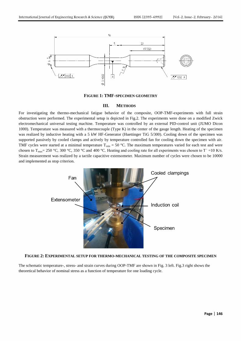
For investigating the thermo-mechanical fatigue behavior of the composite, OOP-TMF-experiments with full strain
obstruction were performed. The experimental setup is depicted in Fig.2. The experiments were done on a modified Zwick
electromechanical universal testing machine. Temperature was controlled by an external PID-control unit (JUMO Dicon
1000). Temperature was measured with a thermocouple (Type K) in the center of the gauge length. Heating of the specimen
was realized by inductive heating with a 5 kW HF-Generator (Huettinger TiG 5/300). Cooling down of the specimen was
supported passively by cooled clamps and actively by temperature controlled fan for cooling down the specimen with air.
TMF cycles were started at a minimal temperature Tmin = 50 °C. The maximum temperatures varied for each test and were
chosen to Tmax= 250 °C, 300 °C, 350 °C and 400 °C. Heating and cooling rate for all experiments was chosen to T ̇ =10 K/s.
Strain measurement was realized by a tactile capacitive extensometer. Maximum number of cycles were chosen to be 10000
and implemented as stop criterion.
FIGURE 2: EXPERIMENTAL SETUP FOR THERMO-MECHANICAL TESTING OF THE COMPOSITE SPECIMEN
The schematic temperature-, stress- and strain curves during OOP-TMF are shown in Fig. 3 left. Fig.3 right shows the
theoretical behavior of nominal stress as a function of temperature for one loading cycle.

International Journal of Engineering Research & Science (IJOER) ISSN: [2395-6992] [Vol-2, Issue-2, February- 2016]
Page | 147
FIGURE 3: LEFT: SCHEMATIC TEST PROCEDURE OF TMF OUT-OF-PHASE TESTS: COURSE OF TEMPERATURE
AND RESULTING STRAIN AND NOMINAL STRESSES. RIGHT: σN -T and σN – ε tme
– HYSTERESIS LOOPS
DURING THERMOMECHANICAL LOADING [18]
From the measured hysteresis loop stress amplitude or medium stress can be taken. In contrast the resulting strains like total
strain amplitude or plastic strain amplitude cannot be determined directly from these hysteresis loops. Total strain of the
specimen during TMF-loading consists of a thermal component εth
and a mechanical component εtme
:
εt (T, t) = εtme
(t) + εth
(T,t) (1)
For calculating the thermal strain component εth
, reference cycles with σN = 0 (see Fig. 2) were performed before the actual
test. With knowledge of εth(T,t), according to Equation 1 εt(T,t) can be determined for the required εtme
(t). Thus enabling a
conversion of stress-temperature-hysteresis into stress-strain-hysteresis (see Fig.3) and consequently a determination of
characteristic values of the materials response to loading like plastic strain amplitude εa,pl or total strain amplitude εa,t.
IV. RESULTS
4.1 Microstructure
Fig. 4 a) shows an optical micrograph of the composite microstructure. The darker reddish phase depicts the alumina and the
brighter reddish phase the copper-based matrix material. The composite shows a very homogeneous distribution of the fine
alumina phase in the matrix material. There is also a third phase recognizable with a slight darker color (marked in Fig.4 a))
which is assumed to be agglomerates of aluminate (in reference to investigations by [9]).
FIGURE 4: A) OPTICAL MICROGRAPHS OF THE MICROSTRUCTURE OF COMPOSITE SAMPLES (100X) (ARROWS:
ALUMINATE PHASE) B) SCANNING ELECTRON IMAGES OF COMPOSITE SAMPLES (5000X) C): μ-CT SCAN

International Journal of Engineering Research & Science (IJOER) ISSN: [2395-6992] [Vol-2, Issue-2, February- 2016]
Page | 148
Fig. 4 b) shows SEM micrographs of the composite microstructure. The darker phase represents alumina and the copper
matrix appears as a brighter phase. Beside some coarse agglomerates of alumina with dimensions of about 5-20 µm (marked
in Fig.4 b)), some residual micro porosity could be observed. This porosity can mainly be found at the alumina-copper
interface. The volume fraction of porosity was determined by using digital image analysis (analySIS pro V.5.1) of SEM
images at 5000x magnification and was specified to 0.36 vol-%. The alumina content was then calculated by taken the
above-mentioned closed porosity into account to a value of 55.3 vol.-percent. Additional X-ray micro computed tomography
(µ-CT) investigations revealed in some specimen cracks in the alumina preform, which have been filled with pure copper
(Fig. 4 c)) during the MMC consolidation process.
4.2 Thermo-mechanical fatigue
4.2.1 Lifetime behavior
Fig. 5 shows the temperature–lifetime curve determined for the composite specimens. Due to limited sample material of the
composite for each temperature two specimens were tested. The results show only small scatter of the lifetime for each load
temperature level. At a maximum temperature of 400 °C, the average load cycles to specimen failure were about 60 cycles.
With decreasing maximum temperature, the lifetime increases, as expected. The medium load cycles to specimen failure for a
maximum temperature of 350 °C was 590 cycles, at 300 °C, an average life time of 9150 cycles was reached (disregarding
the third data point were stop criterion of 10000 cycles was reached). At temperatures below 250 °C the specimen life time
was consistently above the stop criterion of 10000 cycles. Neglecting these data points, a linear correlation between Tmax and
log Nf could be found. Unfortunately the experimental setup allowed no heating of pure copper samples with temperatures
above 350 °C, where copper reaches 4820 cycles to failure.
10 100 1000 10000
250
300
350
400
450 Cu-Al2O
3
Cu
Te
mp
era
ture
Tm
ax in
°C
Number of cycles to failure Nf
FIGURE 5: TEMPERATURE-FATIGUE LIFE CURVE OF THE COMPOSITE SAMPLES
4.2.2 Cyclic deformation behavior
Fig. 6 shows exemplary cyclic deformation curves with determined plastic strain amplitude εpl,a (left) and measured stress
amplitude σa (right) of the composite specimen. The plastic strain amplitude εpl,a was calculated from hysteresis curves
recorded during testing. It can be seen that the composite shows at a maximum temperature of Tmax = 300°C a slow softening
material behavior, with increasing plastic strain amplitude up to 100 cycles and a subsequent stabilization of εpl,a. The stress
amplitude shows at the same time a continuous decrease up to specimen failure. At Tmax = 350 °C the plastic strain amplitude
stays almost constant up to 100 cycles and shows than a small steady decrease of the plastic strain amplitude. The measured
stress amplitude nevertheless shows a steady decrease until specimen failure, which can be attributed to cyclic softening of
the composite material. At Tmax = 400 °C in the first cycles some big steps are observed in the plastic strain amplitude and
subsequent rather slow softening indicated by increasing plastic strain amplitude. The measured stress amplitude was found

International Journal of Engineering Research & Science (IJOER) ISSN: [2395-6992] [Vol-2, Issue-2, February- 2016]
Page | 149
to be constant until specimen failure at 66 cycles. Initial plastic strain amplitude, as well as the stress amplitude in the first
cycle, is dependent of the temperature and increases with rising temperature regime, as expected.
10 100 1000 100000,000
0,002
0,004
0,006
0,008
0,010
0,012
0,014
Tmax
= 400 °C
Tmax
= 350 °C
Tmax
= 300 °C
pl,a
in µ
m/m
m
Number of cycles N
10 100 1000 10000200
300
400
500
600
a in
MP
a
Number of cycles N
Tmax
= 400 °C
Tmax
= 350 °C
Tmax
= 300 °C
FIGURE 6: EXEMPLARY CYCLIC DEFORMATION CURVES WITH PLASTIC STRAIN AMPLITUDE εpl,a (LEFT) AND
STRESS AMPLITUDE σa (RIGHT) OF THE Cu-Al2O3 COMPOSITE
4.2.3 Fracture surface investigations
Fig. 7 shows the fracture surface of a specimen tested with maximum temperatures of 300 °C. Crack initiation was found on
the specimen surface and is visible as oval area, where the fracture surface appears to be slightly smoother, but a coarse
alumina phase with a diameter of about 20 µm.
FIGURE 7: SEM MICROGRAPHS OF A FRACTURE SURFACE OF A SPECIMEN AT DIFFERENT MAXIMUM
TEMPERATURES Tmax = 300 °C
Fig.8 shows the fracture surface of a specimen tested with Tmax = 350 °C. Here the crack initiation can be also found on the
sample surface and offers the same morphology as seen in Fig.7. The remaining crack surface seems to be strongly
deformed, due to the fact that specimen fracture was not detected properly and the two opposing fracture surfaces collided
after specimen failure. Inside the found crack origin no heterogeneities or coarse phases were found.

International Journal of Engineering Research & Science (IJOER) ISSN: [2395-6992] [Vol-2, Issue-2, February- 2016]
Page | 150
FIGURE 8: SEM-PICTURE OF THE FRACTURED SURFACE OF SPECIMEN AT MAXIMUM TEMPERATURES Tmax =
350 °C
Fig.9 shows the fracture surface of a specimen tested with maximum temperature 400 °C. Here again the crack initiation can
be found on the sample surface and directly at the crack origin a coarse irregular formed phase of alumina could be found
with a diameter of about 30 µm. The micro porosity found in the microstructural investigations can be noticed in the crack
origins, but due to its small dimensions and to its homogeneous distribution in the specimen volume, this porosity is hence
assumed not to be of significant relevance for crack initiation or crack propagation.
FIGURE 9: SEM-PICTURE OF THE FRACTURED SURFACES OF SPECIMEN AT MAXIMUM TEMPERATURES Tmax =
400 °C
V. DISCUSSION
As shown in Fig.6 the MMC specimens show rather softening material behavior with increasing temperature. This is in well
agreement to results from [18-21], which all showed a cyclic softening of aluminum-ceramic composites with increasing
temperature. In [17] cyclic softening of the composite was attributed to the aging process of the aluminum alloy used during
thermal cycling. In contrast, copper is much less sensitive to the temperatures occurring in the conducted experiments than
aluminum, which shows at all investigated temperatures softening during cyclic TMF-loading [17, 18]. It can be assumed
that the cyclic softening of the copper-alumina composite is due to continuous interface damage during cyclic loading similar
to the findings in [21]. However, further investigations regarding the microstructural damage evolution are required to proof
this assumption. It can be stated that the plasticity of the composite is mostly defined by the metallic phase. Therefore the
increase of εtme
with increasing temperature is compensated mainly by the copper phase, thus leading to a behavior which is
probably dominated by the behavior of the metallic phase. Experiments with non-reinforced copper samples at 350 °C
showed no damage initiation within the defined ultimate number of cycles. This clearly indicates the problems arising from
the multiphase microstructure leading to stress concentrations inside the material due to notch effects and thermal expansion
mismatch between metal and ceramic phase. Future investigations have to focus on the TMF-behavior of the pure copper
phase at high temperatures and interface damage accumulation in the composite during TMF-loading for a further
understanding of the damage mechanisms. The small scattering of TMF lifetimes nevertheless points out a reproducible

International Journal of Engineering Research & Science (IJOER) ISSN: [2395-6992] [Vol-2, Issue-2, February- 2016]
Page | 151
damage accumulation mechanism for each maximum temperature. As seen from the fracture surface analyses, crack
initiation always occurs at or near the surface. Coarse alumina phase could be observed often in or near the crack initiation
site. Thus heterogeneities in microstructure and especially at the surface can be assumed to be critical in terms of crack
initiation. If coarse alumina agglomerates were found in the crack origin, it is noteworthy that these agglomerates were
always the biggest agglomerates to be found on the fracture surface and that they probably act as inner notches und therefore
supports the hypothesis of inner stress concentrations arising due to the interpenetrating structure. Thus they especially take
effect on the specimen surface, where stress concentrations from surface irregularities additionally arise. Taking into account
that most of such agglomerates found in microstructural investigations showed dimensions between 5 µm – 20 µm, it can be
concluded that reducing agglomerate size in the preform is a possible way to reduce stress concentration around the ceramic
phases and therefore improve fatigue life of the composite. Furthermore the reproducibility of the specimen life time can lead
to the conclusion that crack initiation was similar in all specimens and inner defects like cracks in the preform (Fig 4 c)) or
porosity inside the specimen volume (Fig 4 b)) play an inferior role for crack initiation.
VI. CONCLUSION AND OUTLOOK
The present work delivered a first approach on characterizing the out of phase thermal-mechanical fatigue (OOP-TMF)
behavior of a copper-alumina composite with an interpenetrating network structure:
The microstructure of the copper-alumina composite manufactured via squeeze casting showed a mostly
homogeneous distribution of metallic and ceramic phase in the investigated specimens. Only few heterogeneities
like coarse alumina agglomerates and a low level of porosity were observed.
The determined temperature – life time diagram showed only small scattering at each temperature, thus confirming
the reproducibility of the specimen manufacturing by squeeze casting. It also delivers a first approach on the
maximum temperature – lifetime correlation under OOP-TMF conditions of this composite.
The lifetime of pure copper under the investigated OOP-TMF conditions was found to exceed the lifetime of the
composite significantly. This can be attributed to inner stresses arising in the composite from the mismatch of
thermal expansion coefficients between copper and alumina and to stress concentrations around coarse alumina
phases.
The investigated cyclic deformation behavior revealed cyclic softening at all investigated temperatures. Strongest
softening is observed at Tmax = 400 °C and is assumed to be arise from the properties of the metallic phase and/or
interface damage accumulation, even so this point has not been proven yet.
Crack initiation was always observed at the specimen surface or surface near areas. Coarse alumina phases in this
region can play a critical role in crack initiation and have to be avoided during preform fabrication if possible.
Future work has to supply a comparison to squeeze casted pure copper, regarding the lifetime and cyclic deformation
behavior to fully understand the mechanisms observed in the composite. For a detailed insight into the composite damage
behavior, crack propagation should be regarded further, e.g. using computer tomographic investigations for crack localization
and subsequent metallographic preparation for detailed analyses of crack paths.
ACKNOWLEDGEMENTS
The financial support within the project “Kupfer-Keramik-Verbundwerkstoffe mit Durchdringungsstruktur (WA 1122/6-1)
from the German Research Foundation (DFG) is gratefully acknowledged. The authors also wish to thank the project partner
Materials Research Institute Aalen (IMFAA) for the manufacturing of the investigated material.
REFERENCES
[1] R.D. Joseph,” Copper and copper alloys” ASM International Handbook, 2001
[2] A. Luedtke, “Thermal management materials for high-performance applications”, Advanced Engineering Materials, pp.132-144,
2004

International Journal of Engineering Research & Science (IJOER) ISSN: [2395-6992] [Vol-2, Issue-2, February- 2016]
Page | 152
[3] S. Long, O. Beffort, Moret Uzwil, G. Thevoz, P., “Processing of Al-based MMCs by Indirect Squeeze Infiltration of Ceramic
Preforms on a Shot-Control High Pressure Die Casting Machine”, Aluminium , pp.82–89, 2000
[4] A. Mattern, B. Huchler, D. Stuadenecker, R. Oberacker, A. Nagel, M.J. Hoffmann,” Preparation of interpenetrating ceramic-metal
composites”, Journal of the European Ceramic Society, pp.3399–3408, 2004
[5] A. Neubrand, A. Nagel, “Herstellung von Metall-Keramik-Verbundwerkstoffen durch Druckgießen“, Giesserei pp.156-160, 2007
[6] C. Garcia-Cordovilla, Öpios. E., J. Narciso, “Pressure infiltration of packed ceramic particulates by liquid metals”, Acta Materialia
pp.4461–4479, 1999
[7] M. Bahraini, L. Weber, J. Narciso, A. Mortensen, “Wetting in infiltration of alumina particle preforms with molten copper”, Journal
of Material Science pp.2487–2491, 2005
[8] H. Xing, X. Cao, W. Hu, L. Zhao, J. Zhang, “Interfacial reactions in 3D-SiC network reinforced Cu-matrix composites prepared by
squeeze casting”, Materials Letters, Vol. 59, Issue 12, , pp. 1563-1566, May 2005
[9] O. Lott, Interface Design of Copper/Alumina Composites with Interpenetrating Phase Structure. PhD thesis, Sydney, 2012
[10] K. Prakasan, S. Seshan, “Microstructure and mechanical properties of squeeze-cast copper”, Transactions of the American
Foundrymens Society, pp.23–26, 1998
[11] V. Ganesh, N. Chawla, “Effect of reinforcement-particle-orientation anisotropy on the tensile and fatigue behavior of metal-matrix
composites”, Metall. Mater Trans. A, 35 (1), pp. 53–61. 2004
[12] O. Hartmann, K. Herrmann, H. Biermann, “Fatigue Behaviour of Al-Matrix Composites”, Adv. Eng. Mater., Vol.6 (7), pp. 477–485,
2004
[13] M. Papakyriacou, H. R. Maye; S. E. Tschegg-Stanzl, M. Gröschlm, “ Near-treshold fatigue crack growth in Al2O3 particle
reinforced 6061 aluminium alloy”, Fatigue Fract Eng M, Vol. 18 (4), pp. 477–487, 1995
[14] T. Nicholas, S. M. Russ, R. W. Neu, N. Schehl, „Life prediction methodology for titanium matrix composites“, American society for
testing and materials, No. 1253, pp. 595-617, 1996
[15] S. M. Russ, T. Nicholas, M. Bates, S. Mall, “Life prediction in a [0/90] metal matrix composite under isothermal and
thermomechanical fatigue”, Failure Mech High-Temp Compos Mater, 1991
[16] S. M. Russ, C. J. Boehlert, D. Eylon, „Out-of-phase thermomechanical fatigue of titanium composite matrices,“, Mater Sci Eng A,
Vol. 192(193), pp. 483-489, 1995
[17] A. M. Klaska, T. Beck, A. Wanner, D. Löhe“Thermisch-mechanisches Ermüdungsverhalten der partikelverstärkten
Aluminiumknetlegierung EN AW-6061-T6 und die Entwicklung von Eigenspannungen im Matrixwerkstoff unter thermisch-
mechanischer Beanspruchung“, Mat.-wiss. u. Werkstofftech., Vol. 37 (8), pp. 637–648, 2006
[18] O. Ulrich, “Isothermes und thermisch-mechanisches Ermüdungsverhalten von Verbundwerkstoffen mit Durchdringungsgefüge
(Preform-MMCs)”, Doctoral Thesis, Karlsruhe Insitute of Technology (KIT), Karlsruhe, Germany, 2013
[19] T. Beck, K.-H. Lang, D. Löhe, „Thermal-mechanical fatigue behaviour of cast aluminium alloys for cylinder heads reinforced with
15 vol.% discontinuous Al2O3(Saffil) fibers”, Int. J. Mater. Prod. Tec., Vol. 18, pp. 160-177, 2003
[20] L. Quian, Z. Wang, H. Toda, T. Kobayashi, “High temperature low cycle fatigue and thermos-mechanical fatigue of a 6061 Al
Reinforced with SiCw”, Mat. Sci. Eng. A, Vol 291, pp. 235-245, 2000
[21] J. P. Quast, C. J. Boehlert, “The out-of-phase thermomechanical fatigue behavior of Ultra SCS-6/Ti-24Al-17Nb-xMo (at.%) metal
matrix composites”, Int. J. Fat., Vol.32, pp.610-620, 2010