THE NEW BobCAD-CAM - Amazon S3 · With the release of BobCAD-CAM V29, not only are we delivering...
16
THE NEW BobCAD-CAM Cutting Edge CNC Production Power V29 MILL | MILL TURN | LATHE | ROUTER | PLASMA | LASER | WATERJET | WIRE EDM
Transcript of THE NEW BobCAD-CAM - Amazon S3 · With the release of BobCAD-CAM V29, not only are we delivering...

THE NEW BobCAD-CAM
Cutting Edge CNC Production Power
V29
MILL | MILL TURN | LATHE | ROUTER | PLASMA | LASER | WATERJET | WIRE EDM
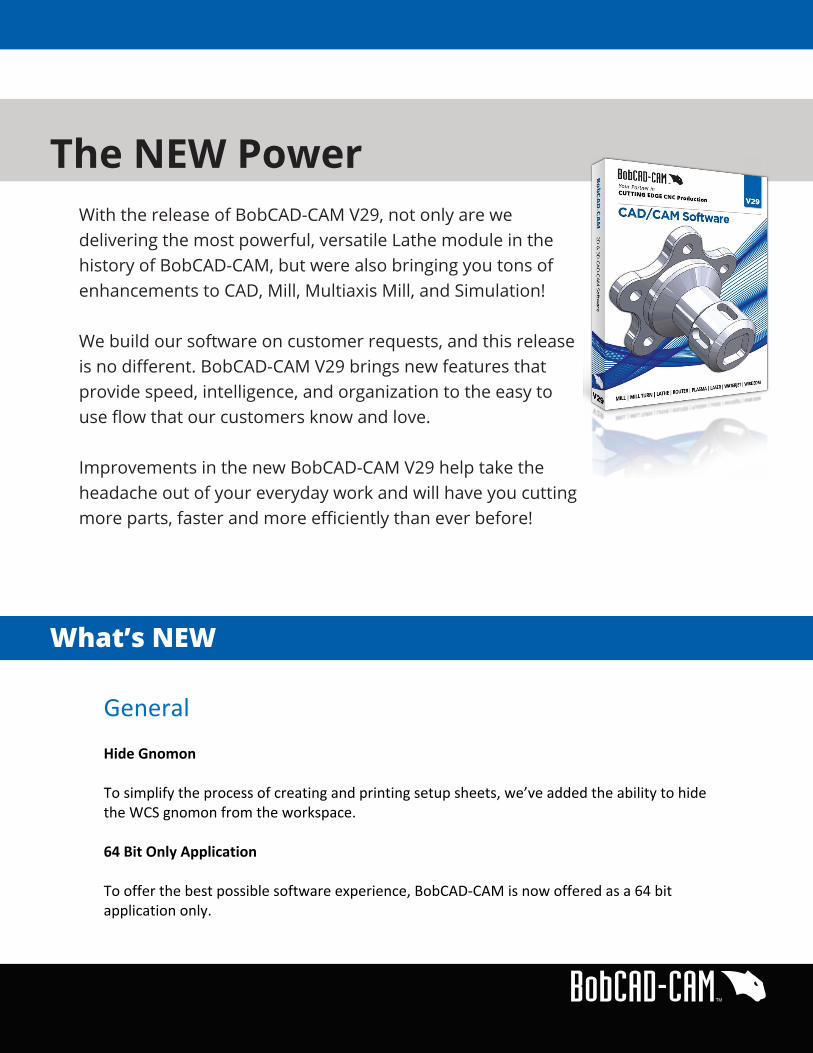
With the release of BobCAD-CAM V29, not only are we delivering the most powerful, versatile Lathe module in the history of BobCAD-CAM, but were also bringing you tons of enhancements to CAD, Mill, Multiaxis Mill, and Simulation!
We build our software on customer requests, and this release is no different. BobCAD-CAM V29 brings new features that provide speed, intelligence, and organization to the easy to use flow that our customers know and love.
Improvements in the new BobCAD-CAM V29 help take the headache out of your everyday work and will have you cutting more parts, faster and more efficiently than ever before!
What’s NEW
The NEW Power
General Hide Gnomon To simplify the process of creating and printing setup sheets, we’ve added the ability to hide the WCS gnomon from the workspace. 64 Bit Only Application To offer the best possible software experience, BobCAD-‐CAM is now offered as a 64 bit application only.

CAD Enhancements Spun Profile Spun Profile is perfect for lathe jobs where it’s tough to find the overall outline of the part. Using this new feature, you simply pick the direction of the rotation, select the surface, and BobCAD-‐CAM does the rest. Chain Filleting This new feature can reduce mouse clicks associated with setting up filleting operations by as much as 75% by giving you the ability to fillet an entire chain, or multiple chains, of entities at one time. Quick Unit Type Access from the Status Bar Switching between unit types is now easier than ever using the new drop down menu in the status bar. File Open Options Many of our clients have told us about frustrations they have receiving files from their clients that may have been improperly saved, which can cause files with many solids to open as a one single solid. This can cause a lot of unnecessary CAD work and a lot of back & forth phone calls with your client. We have solved this by giving users Open File Options for supported file types. Now you can choose whether to open Curves, Solids, or both. For the solid model itself, you can choose to open the file while keeping the separate bodies as saved in the file, or choose to have our software attempt to join them.

CAM Enhancements Backplot The simulation is an incredibly powerful tool that allows you to check everything from cut time to part deviations. In some cases, you may just need to check simple tool movement on a single operation. Previously, this required a lot more clicks to isolate a single operation and launch the simulation. But now, BobCAD-‐CAM gives you a way to track tool movements for a single operation without the need to launch the simulation. By right clicking on an operation and selecting the Backplot options, you’re now able to see the tool movement for a single operation directly in the CAD window for any mill, lathe, mill turn, or wire EDM jobs! Update All Geometry (CAM Tree) There are times when, for whatever reason, something about the feature geometry changes. Maybe one or two features on the CAD model have been edited in the CAD Tree, or even worse, maybe the machine zero has changed and now every single feature in the CAM Tree needs to have the geometry re-‐associated. To cure headaches like these, the Update All Geometries option has been added to the Job Tree. Using this feature, you can now easily update or re-‐associate all modified geometries associated with the CAM Tree and re-‐compute toolpath in one easy step. Groups (CAM Tree) Groups give you greater organizational control over complicated jobs by allowing you to create folders inside of your CAM Tree that you can then drag and drop features into. Not only does this save space in the CAM Tree, but it also allows you to control toolpath options on all features inside of the folder at the folder level.

Mill Enhancements Mill Express Thread Milling Enhancements
Tapered Thread Milling As one of the more popular feature requests in V29, BobCAD-‐CAM now allows you to easily machine tapered (pipe) threads. Thread Mill Side Roughing This feature allows you to set up incremental side roughing steps to reach the final size of the thread. Machine Compensation Support for Thread Milling To give you more control to make adjustments at the machine, we’ve added Machine Compensation to the patterns page for threading operations. New Thread Mill Tool Types Single point threading tools and multiple tooth Thread Mill are now supported as separate tool types. The tool definitions have also been enhanced to allow for a more accurate simulation, and the definition of multiple different thread types.
Spiral Pocketing for Circles To give your circular pockets the cleanest cuts possible, we’ve added a spiral pattern option to the 2 Axis Pocket wizard. Helical Arc Output for Spiral Entities BobCAD-‐CAM will now output helixes in the posted code for all of your spiral cuts, which can reduce g-‐code by hundreds of lines of code. For machines that cannot accept a helix, we have added Post Block: “553. Break helical arcs into lines? Y/N” which utilizes the arc break tolerance on block 320.
Mill 3 Axis Standard Advanced Pocket Calculation Improvements Every job has to be roughed out, and it’s tough find a quicker, more efficient toolpath than the Adaptive Roughing pattern for the Advanced Pocket toolpath. However, larger jobs and tighter tolerances used to take much longer to compute. But now, we’ve made a great toolpath even better by improving the calculation speed and providing you with smoother lead in motions. Tests show calculation speed improvements in the range of 20-‐90%!
Improved Open Shape Detection In many cases, large areas inside a pocket have already been cleared by a previous operation. Forcing the software to start the cuts in the void, while not trying to cut air, can save a lot of time. To help with these scenarios, internal hole boundaries are now supported for Advanced Pockets by using dashed entities.
Mill 3 Axis Pro Overall Mill Enhancements Gouge Checking Gouge checks are now available for all the Mill Pro toolpaths, allowing you to set various clearance options for the different components of the tool, select which surfaces you would like to check, and choose either retract tool or one of the six other strategies to use in case of a gouge detection. This option can also be used to give you even more control over how particular surfaces are handled. You can choose surfaces to give additional allowance to, or even avoid particular surfaces completely. Rest Finishing from STL Stock Model Rest finishing options have been added to the Advanced Planar, Advanced Z Level Finish, Equidistant, and Project Curve toolpaths to give you more power over making sure each tool finishes only what is needed while creating the shortest program possible. And there are two powerful solutions for handling your rest finishing needs:
Utilizing the Previous Tool Information – This option is available for when you’re using a similar type of toolpath combined with a smaller tool that can go in to clean up areas where the previous larger tool could not fit. This calculation has been enhanced with a new 3D trimming boundary to provide a higher degree of precision.

NEW -‐ STL Stock Model – The new Stock Model option lets you to import the cut stock model from simulation, allowing you to work with the most precise rest finishing calculations possible.
Improvements to the Angle Range Calculations Angle Range is an incredibly useful tool that enhances the amount of control the user has over the tool, and now the new and improved algorithm that drives the angle range calculations delivers an even higher degree of accuracy. Advanced Rough
Improved Calculation Speed and Toolpath Quality Every job has to be roughed out, and it’s tough find a quicker, more efficient toolpath than the Advanced Roughing toolpath. However, larger jobs and tighter tolerances used to take much longer to compute. But now, we’ve made a great toolpath even better by improving the calculation speed and providing you with smoother lead in motions. Tests show calculation speed improvements in the range of 20-‐90%! Parallel Cutting – Profile After For even more control, advanced rough now provides you with the option to turn Profile After on and off when the Parallel pattern is in use. Profile After creates an additional profile pass at the end of each depth. There is also a spacing option which allows you to control how close the initial passes are to the profile. Stock Thickness Detection for Rest Machining Detect Stock Thicker Than BobCAD-‐CAM has added Detect Stock Thicker Than to the Advanced Rough toolpath. This option allows you to focus the toolpath on stock consisting of a particular range of thickness. Setting a value here will force the toolpath to ignore any stock whose thickness does not meet this value. This is another tool to give you as much power as possible without the need to create new geometry to use as a boundary. Tool Outside, Inside, Center, and Offset Boundaries for Advanced Rough Because our users like the boundary options on the Mill Pro finishing passes so much, we’ve now added them to the Advanced Rough toolpath. With this, you’re able to set the tool to keep to the center, stay inside, stay outside, or even offset its spacing from the boundary without ever needing to create additional geometry.
Flatlands
Parallel and Adaptive Patterns for Flatlands Flatlands is an incredibly easy way to face off all the flat areas of the part, without having to worry about setting depth. No matter how many different depths the flat areas exist on, Flatlands will finish them all, and now you have more pattern options to choose from. In addition to the previously available Offset style pattern, we’ve added a Parallel and an Adaptive Roughing style pattern, with adaptive roughing providing an optimized adaptive toolpath, which will approach from the air to reduce the overall machining time.
Advanced Planar
Round Corners The Radius value for Round Corners in the Advanced Planar toolpath has been replaced with Maximum Deviation. Step Down The Advanced Planar toolpath now has a Step Down option, giving you the ability to set up multiple passes.
Advanced Z Level Finish
Machine Vertical Walls Only In order to give you more control over how surfaces are cut, Machine Vertical Walls Only has been added to Advanced Z Level Finish. Full Contour Pass Options By default, the Spiral pattern on the Advanced Z Level toolpath performs one full pass, or “Full Contour”, at the same depth before beginning the spiral, and one more at the end of the spiral. With the addition of some new options, you can now choose to exclude the first, last, or both closed contours from the spiral.
Mill 4 Axis Standard Optimized Multiaxis Posting Settings (4 Axis Standard & Greater Modules) The Multiaxis Posting page in the CAM Wizards has been reorganized to simplify the available parameters and make them clearer. The available Angle Pair and Pole Handling parameters are now properly updated based on the machine type (4 axis or 5 axis) and job. Mill 4 Axis Pro Extend Edge Curve To save you time on having to create additional geometry, we’ve added Extend Edge Curve to the Surface Quality section of the Morph Between 2 Curves and Parallel to Multiple Curves toolpaths. This option forces the software to extend the edge curve in the background so the toolpath does not wrap around the open ends of a curve when the surface continues beyond the ends of the curve. Exact Stepover Option To assist with surface quality, we’ve added a new exact stepover option to the Morph Between 2 Curves and Parallel to Multiple Curves Toolpaths. In the Advanced dialog of the Surface Quality section, there is now a Stepover Calculation option that allows you to select from an Approximate or Exact calculation method. New Flowline Toolpath The 4 Axis Pro toolpaths now include a Flowline toolpath that requires only a single surface selection, allowing you to get a flowline-‐style toolpath faster than ever. The toolpath follows the U or V direction of the selected surface and you control the toolpath by setting the Style to either “Along” or “Around”. New Mirror Option To save you time on creating finishing paths for symmetrical part geometry, the Mirror option was added to the Roughing tab of the Multiaxis Wizard, allowing you to mirror the toolpath across any axis. Simply turn the mirror option on, select an axis, and compute the toolpath.
Common Direction Tilting Options When using multiaxis toolpaths, it is normally good practice, in many cases, to keep the tool normal to the surface at all times. However, in some cases, this can cause more movement than you would want. With Common Direction, the aim is to find a single tool axis orientation on the full toolpath or a single contour that works well on all areas of the selected surfaces. When using Common Direction, the tool axis is set to a normalized, single direction for all toolpath points and the option is available for all tilting strategies. Gouge Checking – Retract Tool Along Tool Plane This new gouge checking strategy moves the tool out of gouging using the tool plane or at a right angle to the tool axis. When gouges are detected, the software moves the tool away from the cutting direction at a right angle (into the tool plane). User Controlled Point Distribution All surface based Multiaxis toolpaths now put the control over toolpath point distribution in your hands. You can define a Maximum Distance and/or Minimum Distance with a Deviation Factor, giving you more control over the tolerance of the final part. Mill 5 Axis Pro Maintain Tilt In many cases, the tilt of the tool is based on the surfaces being cut. Drastic changes in the surface can cause the axis of the tool to shift significantly over a short distance. This shift is most noticeable when the surface normal in fillets changes from 90 to 0. Maintain tilt has been added to the Tool Axis Control tab to resolve these issues. Lathe Enhancements BobCAD-‐CAM is very proud to introduce the newly enhanced Lathe module within the V29 suite of products. With enhancements to the feature types and new toolpath additions to every single operation, this is by far the most powerful lathe system ever offered by BobCAD-‐CAM. Overall Lathe Enhancements The Feature definition for all lathe features has been completely overhauled to deliver a simpler and more flexible system.

New Lathe Tool and Holder Definitions The new lathe system has a complete rework of the lathe tools, including ISO standard insert definition, in addition to easily created tool holders without the need to create geometry! Feature Type and Regions Once a feature has been selected, you choose the Feature Type and a Region. Feature Types – OD, ID, Face, and Back Face Regions – 1 or 2 Constraints The Constraints allow you to define the area in which the toolpath will be generated, without the need to trim and extend geometry.
From Stock – Sets the Top of Feature to the highest point of the stock diameter. From Feature – Sets the Top of Feature to the highest point of the selected feature geometry. Custom – Sets the Top of Feature from the highest point of the selected feature geometry to the value entered. This allows you to pick a point as well.
Extension Extensions allow you to extend and trim the virtual feature geometry without the need to adjust the actual CAD geometry. Choose the Start/End option, then enter the values to trim and extend those virtual geometries along the chain. You can even create them at an angle. All this can be done without the need to touch a CAD tool. Automatic Removal of Undercuts For years, BobCAD-‐CAM has trained users on how to add geometry to a CAD model to act as a bridge over the areas of the geometry. This method allowed you to keep the tool away from particular areas of the model that you did not want cut with a particular operation. The new Undercut option allows you to accomplish the same goal simply by selecting a check box in the Lathe Wizard. With it, you simply pick an entire chain for the feature geometry and select what should be left out, without having to touch a CAD tool. Select Remove Primary Undercut, Remove Secondary Undercut, or both to have complete control over the operation. Rapid Plane The Lathe module now provides you with a Rapid Plane option to give you control over where the rapid motion to the feature ends.
New Lathe Feature Types End Face Feature The End Face Feature makes facing off the part quick and easy, without the need to draw any additional geometry. Groove Feature This feature allows you to choose multiple grooves at one time and lets you rotate the feature for grooves on an angle.
Rotate Rotations of grooving features can be accomplished by entering an angle or picking geometry to align the walls or the floor of the feature with.
Operation Enhancements Each operation has had several enhancements to give you more control over lathe toolpaths. Rough Turning Operation The roughing operation used for both turning and faces received several enhancements and offers a higher level of control.
Various Pattern Types The new version now offers an offset style pattern option that can be used with lathe roughing to assist with cast or custom stock and general efficiency. Sorting Once a pattern is chosen, you can now choose from a Standard or Zig Zag style to give you more control over how your parts are cut. Overlap Once the tool is engaged in a pass, it’s usually preferable to continue up the geometry in order to eliminate steps in the roughing pass. Now, not only can you set the lead out options, but you can set what happens prior to the lead out of each pass. You’re able to set each pass to track back to the distance of the previous pass, set each pass to do mothering before the lead out, or even set a custom distance to track back to.
Rough Allowance Users can now add an additional pass to the groove roughing to clear any steps and leave a consistent amount of material for finishing.
Pattern Repeat Operation The Pattern Repeat Operation used for both turning and facing has received several enhancements and enhanced control.
Various Pattern Types New Pattern and Sorting options for the Pattern Repeat Operation allow you to choose between a Standard or Offset Pattern and set either a Standard or Zig Zag style sorting option. Sorting Once a pattern is selected, you’re now able to choose from a Standard or Zig Zag style cut to get exactly what you’re looking for.
Basic Finish Operation The Basic Finish Operation used for both turning and facing has received several enhancements and more control is offered.
Various Pattern Types When finishing a lathe part, many variables go into deciding how the part should be finished. Between the allowance that has been left, the tool being used, and the shape of the part, a basic continuous pass on the part may not always be ideal. In previous versions, breaking up a finishing pass into separate directions required separate features. With the new pattern options, you now have a way to Alternate between face and turn methods, all within one operation. When you choose the Alternate method over the standard Continuous method, you have the option to Face Vertical Only, Turn Diameter Only, handle both scenarios at once, and even decide whether to include or exclude angled walls with a simple check box.
Groove Roughing Operation The Groove Roughing Operation used for both turning and facing has received several enhancements and offers a higher level of control.
Various Pattern Types Grooves now offers combinations of patterns (Standard, Single Pass, and Zig Zag) and sorting options so that a user can cut features exactly how they want them. Sorting If a Standard pattern is selected, you have control over the order of your cuts. Alignment When a Single Pass is selected, you control how to line the tool up with the constraint of the selected geometry. Rough Allowance You’re now able to add an additional pass to the groove roughing to clear any steps and leave a consistent amount of material for finishing. Multiple Depths Grooving Grooves can now be broken into multiple depths by the user. You control whether you want to use multiple depths and how to organize those depths. This option can be used in combination with pecking so that material can be removed a layer at a time. Processing In some cases, the selected geometry causes the toolpath to be broken into separate areas along a number of passes. With the Processing area, you decide how the tool will move between the separate areas of the toolpath.
Groove Finish Operation The Groove Finish Operation used for both turning and facing received several enhancements and offers a higher level of control.

Force Down Cutting Grooving tools are always more effective when the force is applied straight down into the material. The Groove Finish Operation now gives you the option to force down the cutting motion, and even has it set as the default method. You can even apply a custom overlap amount so the final pass will overlap the first, creating a much cleaner finish.
Corner Type How the tool moves from one piece of geometry to the next can make a big difference in the final product. In some cases, users want to round the tool over corners to help de-‐bur the part. In other cases, parts require precise, sharp corners. The new Sharp Corner option gives you the best of both worlds. Rapid on Entry Options Approach Options have now been added to the Rapids Page. In addition to the Rapid Exit options, you can now control the approach options to better control every aspect of the lathe job. Leads The new lathe module includes tons of new lead options to go along with the custom lead that was already available. Simulation Enhancements Smart View (Rotation Cube) To make switching views in simulation easier, a new Smart View option has been added and can be used with the Rotation Cube. While on, the Rotation Cube allows you to click on the face of the cube to shift to the Top, Bottom, Right, Left, Front, and Back views. Clicking on the corners of the Rotation Cube allows you to quickly shift into the various isometric views. Automatic Quality Improvements When simulating stock removal, the graphic quality is always turned down. This helps to facilitate a smooth running simulation. Once the simulation has stopped, there has been an option to refine the graphic quality to show a more accurate representation of the result. This refine now happens automatically when the simulation is stopped without the need to do so manually.
Measure Distance Between Components The Measure Distance function now allows you to measure distances between machine components as well as distances on the stock itself. Video Capture For quite some time now, users have been able to save an entire simulation as an .exe file, which has allowed users to share the simulation and all the simulation controls with project decision makers. Sometimes, sharing that level of power, control and data can be counterproductive. Now you have the option to simply capture a video of the graphics window, allowing you to keep things simple, when needed. Program Based Stop Conditions Additional options have been added to the Program Based Stop Conditions. In addition to the options to Stop on Tool Change and Stop on Operation Change, the new On Block option provides further stop control. This new option allows you to force the simulation to stop at a user-‐defined move block. The Stop Before Occurrence options gives you the option to force the simulation to stop before the specified type of occurrence. Set All to Initial Values Users now have the option to set all axis values to the initial starting points of the program. Robust Shortcut Keys New Shortcut Keys are now available for many of the options in simulation. It’s now possible to switch between backplot mode and material removal mode with the press of a key. Other additions include tool focus options, simulation speed and view controls, and all the run controls.
BOBCAD-CAM, INC - SALES