The Meister for AU9290 (EU3907) Users Manual · PRD002608W00 Rev.0200 1/36 . The Meister for AU9290...
36
PRD002608W00 Rev.0200 1/36 The Meister for AU9290 (EU3907) Users Manual Date ‘18. 3.21 Tamagawa-seiki reserves the right to make changes to this document without notice.
Transcript of The Meister for AU9290 (EU3907) Users Manual · PRD002608W00 Rev.0200 1/36 . The Meister for AU9290...

PRD002608W00 Rev.0200 1/36
The Meister for AU9290 (EU3907)
Users Manual
Date ‘18. 3.21
Tamagawa-seiki reserves the right to make changes to this document without notice.

AU9290Meister Users Manual PRD002608W00 Rev.0200 2
Contents
1. Overview............................................................................................................................... 4
2. Operating requirements ........................................................................................................ 4
2.1. PC ...................................................................................................................................... 4 2.2. USB Cable ......................................................................................................................... 4
3. USB port setting ................................................................................................................... 5
3.1. Installation of 「Virtual COM Port Driver」 ................................................................... 5 3.2. Installation of Device Driver ............................................................................................ 6
3.2.1. Automatic installation of Device Driver .......................................................................... 6 3.2.2. Manual installation of Device Driver .............................................................................. 7
3.3. Confirmation of COM Port name ................................................................................... 10
4. How to change language ......................................................................................................11
5. Using 「The Meister for AU9290」 (Basic Version) ............................................................... 13
5.1. Introduction .................................................................................................................... 13 5.2. 「Communication connection」......................................................................................... 13
5.2.1. Display explanation ........................................................................................................ 13 5.2.2. Connection methods ....................................................................................................... 13
5.3. 「Alarm」 ........................................................................................................................... 13 5.4. 「Parameters Window」 .................................................................................................... 14
5.4.1. Change parameters ........................................................................................................ 14 5.4.2. 「Motor」 ........................................................................................................................... 15 5.4.3. 「Trial Operation」 ............................................................................................................ 15
6. Using 「The Meister for AU9290」 (Detail version)............................................................... 16
6.1. Introduction .................................................................................................................... 16 6.2. Setting Display :「Pulse」, 「PIO」, 「Communication」 ................................................ 16 6.3. 「Communication」 :「Pulse」, 「PIO」, 「Communication」 ............................................ 17
6.3.1. Display explanation ........................................................................................................ 17 6.3.2. Connection method ......................................................................................................... 17
6.4. 「Status」........................................................................................................................... 17 6.4.1. Display explanation :「Pulse」, 「PIO」, 「Communication」 ........................................ 17 6.4.2. 「Data Download」 :「Pulse」, 「PIO」, 「Communication」 ........................................... 18 6.4.3. 「Alarm History」 :「Pulse」, 「PIO」, 「Communication」 ............................................ 19 6.4.4. 「Drive Command」 :「Pulse」, 「PIO」, 「Communication」 ......................................... 19 6.4.5. 「Drive Status」 :「Pulse」, 「PIO」, 「Communication」 ................................................. 20 6.4.6. 「Drive monitor」 :「Pulse」, 「PIO」, 「Communication」............................................... 20 6.4.7. 「I/O Status」 :「PIO」,「Pulse」(Only Enable) ................................................................ 20

AU9290Meister Users Manual PRD002608W00 Rev.0200 3
6.5. 「Parameters」 .................................................................................................................. 21 6.5.1. Contents in Subtab ......................................................................................................... 21 6.5.2. Change parameters ........................................................................................................ 21 6.5.3. 「Primary」 :「Pulse」, 「PIO」, 「Communication」 ........................................................ 22 6.5.4. 「Basic Parameters」 :「Pulse」, 「PIO」, 「Communication」......................................... 22 6.5.5. 「PIO」 :「PIO」 ............................................................................................................... 23 6.5.6. 「Communication」 :「Communication」 ........................................................................ 23 6.5.7. 「Alarm」 :「Pulse」, 「PIO」, 「Communication」 ........................................................... 24 6.5.8. 「Motor」 :「Pulse」, 「PIO」, 「Communication」 ............................................................ 25 6.5.9. 「Diver」 ............................................................................................................................ 25 6.5.10. 「Origin Search」 :「Pulse」, 「PIO」, 「Communication」 ............................................... 26
6.6. 「Debug 」 :「Pulse」, 「PIO」, 「Communication」 ......................................................... 27 6.6.1. ID input ........................................................................................................................... 27 6.6.2. Change data (parameters) .............................................................................................. 28 6.6.3. Cancel and Initialize....................................................................................................... 29
6.7. 「Trial Operation」:「Pulse」, 「PIO」, 「Communication」 .............................................. 30 6.7.1. 「Trial Operation」 ............................................................................................................ 30 6.7.2. 「Origin Search trial」 ...................................................................................................... 31
7. Trouble shooting ................................................................................................................. 32
7.1. Trouble shooting related to USB port. ........................................................................... 32 7.2. Trouble shooting related to 「The Meister for AU9290」 ............................................... 32
8. Operation with Windows10. ................................................................................................ 33
8.1. Over view of the work in case software is not work. ..................................................... 33 8.2. Preparation ..................................................................................................................... 33 8.3. Work procedure ............................................................................................................... 33
8.3.1. Install batch file「NDPFixit-KB3005628-X86.exe」 ....................................................... 34 8.3.2. Update a Windows .......................................................................................................... 34 8.3.3. Install 「.NET Framework 3.5」 ...................................................................................... 35
8.4. (Reference) About 「.NET Framework」 ......................................................................... 35
AU9290Meister Users Manual PRD002608W00 Rev.0200 4
The Meister for AU9290 (EU3907) Users Manual
1. Overview
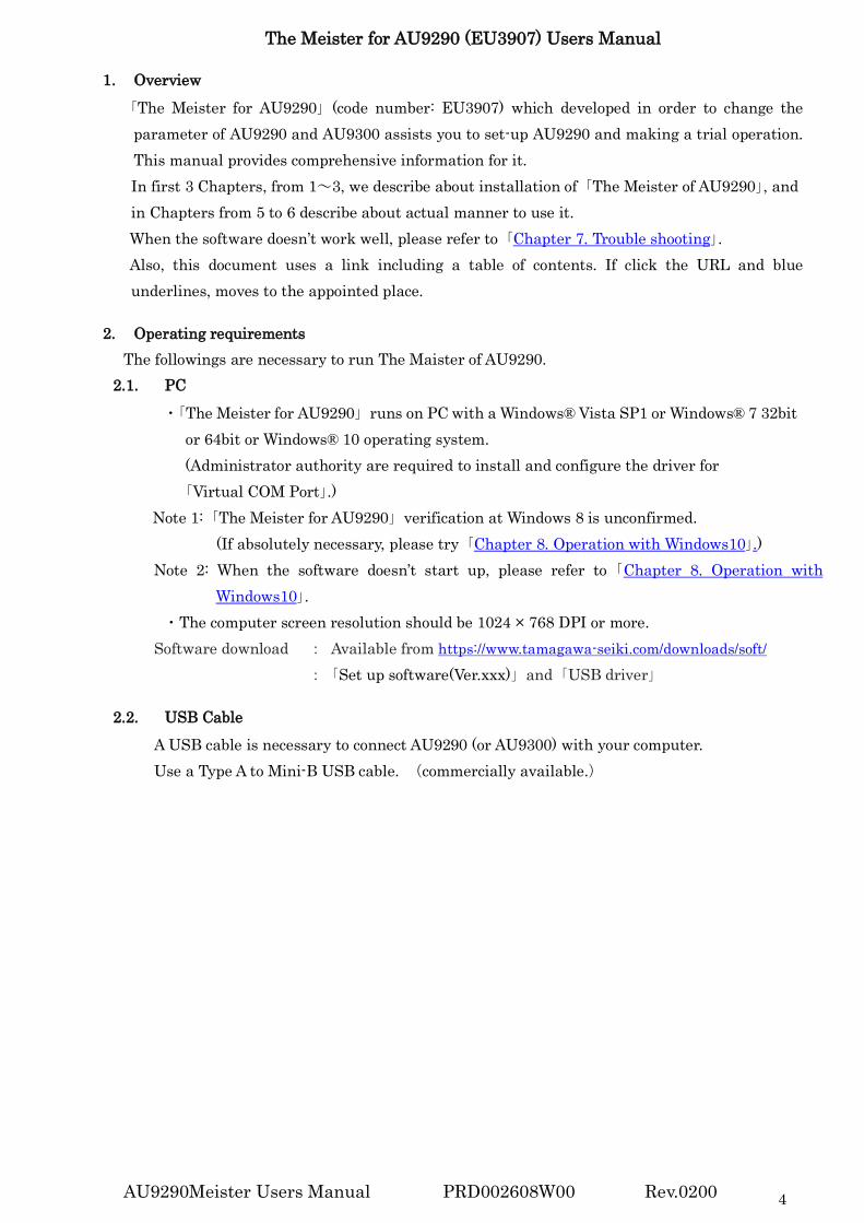
「The Meister for AU9290」 (code number: EU3907) which developed in order to change the parameter of AU9290 and AU9300 assists you to set-up AU9290 and making a trial operation. This manual provides comprehensive information for it. In first 3 Chapters, from 1~3, we describe about installation of 「The Meister of AU9290」, and in Chapters from 5 to 6 describe about actual manner to use it. When the software doesn’t work well, please refer to 「Chapter 7. Trouble shooting」. Also, this document uses a link including a table of contents. If click the URL and blue underlines, moves to the appointed place.
2. Operating requirements
The followings are necessary to run The Maister of AU9290. 2.1. PC
・「The Meister for AU9290」 runs on PC with a Windows® Vista SP1 or Windows® 7 32bit or 64bit or Windows® 10 operating system. (Administrator authority are required to install and configure the driver for
「Virtual COM Port」.) Note 1: 「The Meister for AU9290」 verification at Windows 8 is unconfirmed. (If absolutely necessary, please try 「Chapter 8. Operation with Windows10」.) Note 2: When the software doesn’t start up, please refer to 「Chapter 8. Operation with
Windows10」. ・The computer screen resolution should be 1024 × 768 DPI or more.
Software download : Available from https://www.tamagawa-seiki.com/downloads/soft/ : 「Set up software(Ver.xxx)」 and 「USB driver」
2.2. USB Cable
A USB cable is necessary to connect AU9290 (or AU9300) with your computer. Use a Type A to Mini-B USB cable. (commercially available.)

AU9290Meister Users Manual PRD002608W00 Rev.0200 5
3. USB port setting The USB Driver 「VCP (Virtual COM Port Driver)」 needs to be installed to connect AU9290 (or AU9300) with PC. Manual is as below. 3.1 Installation of driver software 3.2 Set up pf device driver Please obtain this driver software from the following URL.
https://www.tamagawa-seiki.com/downloads/soft/
3.1. Installation of 「Virtual COM Port Driver」
First of all, install Virtual COM Port driver for the communication between the PC and AU9290. This procedure depends on the OS type of your PC.
(1) Open the Windows 「Start」 menu, right-click on 「Computer」, select 「Properties」. (Alternatively, open the Windows 「Start」 menu, select 「Control Panel」 and 「System and
Security」 and click 「System」). Please confirm OS type. ( i.e. 32 bits or 64bits)
(2) Please open the folder 「/USBDriver」 in free provided software package, and select a correct
file from 2 files. 「VPC_V1.3.1_SetUp.exe」 : For 32bitOS 「VCP_V1.3.1_SetUp_x64.exe」 : For 64bitOS」
(3) The warning message will appear, but please proceed with the installation. At the
「InstallShield Wizard」 screen, click 「Next」 to continue.
Select 「Properties」
Confirm OS type
i.e. Select「VPC_V1.3.1_SetUp.exe」. In case of 32bitOS.
Click 「Next」
「Computer」 System
(i.e. 32 bit or 64bit)

AU9290Meister Users Manual PRD002608W00 Rev.0200 6
(4) Running 「Setup Status」, display will change to 「install wizard of Device Driver」. Click 「Next」 to continue.
(5) When the installation is complete, click 「Finish (Complete)」 to end the「Install Wizard of
Device Driver」 program. All are completed for 「Virtual COM Port Driver」 installation.
3.2. Installation of Device Driver Install Device Driver next to make USB connection. There are 2 methods to install Device Driver. If the method 3.2.1 does not work, please try the method 「Chapter 3.2.2 Manual installation of Device Driver」. However, in that case, you must have administrator authority.
3.2.1. Automatic installation of Device Driver (1) Please connect the computer and AU9290 (or AU9300) with a USB cable as Fig 1, and then
turn on the power of AU9290 (or AU9300).
Fig 1 Connection of the computer and Driver
(2) A message such as the one below will be displayed, and the computer will recognize the new hardware and automatically begin device driver installation.
(3) On Windows7, Device Driver software is automatically installed, and it can’t be stopped until installation is completed. It takes about 5 minutes. The following methods are effective to shorten time.
PC
USB Communication Cable.
AU9290 USB miniB
Click 「Next」
Install Wizard of Device Driver
Click 「Finish (Complete)」
Install Wizard of Device Driver
The indicator
During the Installation of Device Software Click here if view the status.

AU9290Meister Users Manual PRD002608W00 Rev.0200 7
(4) After starting installation, please open the indicator in Task Bar. (See above) Please click 「Skip to get Driver Software from Windows Update」, and click 「Yes」to continue.
(5) Display will change to 「Skipped Driver Software from Windows Update」.
(6) When the 「Ready to use」window will be displayed, click 「Close」 to end the installation of Device Driver Software .
3.2.2. Manual installation of Device Driver (1) Prior to the manual installation, you need to change device installation settings. Open the
Windows 「Start」 menu, please input 「Device installation」 in 「Search programs and files」. The following window will be displayed as 「Change of Device installation Settings」(「Device and Printer」 on Control Panel), please click it.
Click 「Skip to get Driver Software from Windows Update」
Click 「Yes」
It has been changed to display 「Acquisition of driver software from Windows update was skipped」.
Installation of Device Software Installation of Device Software
Installation of Device Software
Ready to use
Close
Input 「Device installation」. Select 「Device Installation settings」

AU9290Meister Users Manual PRD002608W00 Rev.0200 8
(2) A new window pops up asking you whether you want Windows to download driver software. Click to select 「No, let me choose what to do」, select 「Never install driver software from Windows update」, and then click 「Save Changes」.
Note: To execute 「Save Changes」, Administrator authority is necessary.
(3) Please connect the computer and AU9290 (or AU9300) with a USB cable as Fig 1, and then
turn on the power of AU9290 (or AU9300). (4) Start 「Device manager」. Starting method is as below. ・Open the Windows 「Start」 menu, right-click on 「Computer」, select 「Properties」. ・Click 「Device manager」 on the window that appears.
(5) Right-click on 「STM32(or STMicroelectronics) Virtual COM Port」 in 「Other Device」, and
select 「Update Driver Software」.
②Please select 「Never install driver software
from Windows update」
③Please select 「Save Changes」
Click 「Properties」
Click 「Device Manager」
Click 「Update Driver Software」
Device Installation Settings
①Please select 「No, let me choose what to do」
Right-click here
Cancel

AU9290Meister Users Manual PRD002608W00 Rev.0200 9
(6) Select the 「Browse my computer for driver software」 on the window that appears.
(7) Click 「Browse…」 and select following folder. In case of 32bitOS: C:¥Program Files¥STMicroelectronics¥Software¥Virtual COM Port Driver In case of 64bitOS: C:¥Program Files (x86)¥STMicroelectronics¥Software¥Virtual COM Port Driver
(8) Please click 「Next」.
(9) When the installation is complete, click 「Close」 to end the 「Update Device Software」.
Select 「Browse my computer for driver software」
Update Driver Software
①Click 「Browse…」
②Select folder and click 「OK」.
③Click「Next」
Update Device Software
Click 「Close」
Update Device Software

AU9290Meister Users Manual PRD002608W00 Rev.0200 10
3.3. Confirmation of COM Port name In order to make communication with AU9290, you must confirm COM Port name. (1) Please connect the computer and AU9290 (or AU9300) with a USB cable as Fig 1, and then
turn on the power of AU9290 (or AU9300). (2) Start 「Device manager」. Starting method is as below. ・Open the Windows 「Start」 menu, right-click on 「Computer」, select 「Properties」. ・Click 「Device manager」 on the window that appears.
(3) Click 「Port」 You will see several COM port names are displayed. Find the COM port name indicated
「STMicroelectronics Visual COM Port」. The COM port name is used for PC to make communication with AU9290 (or AU9300).
Find COM Port name
Click 「Properties」
Click 「Device Manager」.
Device manager
Port

AU9290Meister Users Manual PRD002608W00 Rev.0200 11
4. How to change language Software is available from below URL.
https://www.tamagawa-seiki.com/downloads/soft/ (1) Start 「The Meister for AU9290_ver xxx.exe」.
(2) This is starting display.
(3) This display is coming up next. (Actual operation display) 「Japanese」is selected at first.
(4) In order to change language to English, click 「to English」.
Start 「The Meister for AU9290」
Click「Click here to change language to English.」
「Japanese」is indicated here.
Japanese

AU9290Meister Users Manual PRD002608W00 Rev.0200 12
(5) Click「Yes」
(6) Restart software
(7) This display is coming up next by English mode.
Language is changed to English from now on.
Click「Yes」
「English」is indicated here.
All characters are changed to English.
AU9290Meister Users Manual PRD002608W00 Rev.0200 13
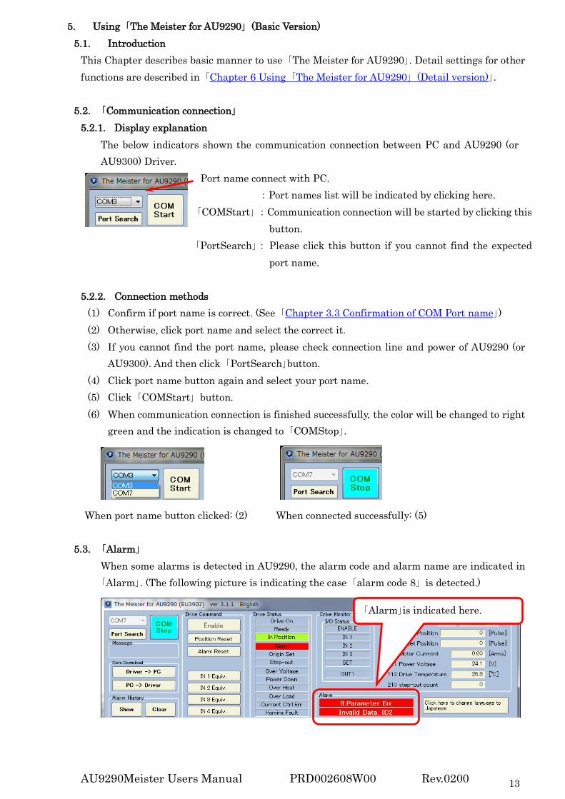
5. Using 「The Meister for AU9290」 (Basic Version) 5.1. Introduction
This Chapter describes basic manner to use 「The Meister for AU9290」. Detail settings for other functions are described in 「Chapter 6 Using 「The Meister for AU9290」 (Detail version)」.
5.2. 「Communication connection」 5.2.1. Display explanation The below indicators shown the communication connection between PC and AU9290 (or
AU9300) Driver. Port name connect with PC.
:Port names list will be indicated by clicking here. 「COMStart」 :Communication connection will be started by clicking this
button. 「PortSearch」: Please click this button if you cannot find the expected
port name.
5.2.2. Connection methods (1) Confirm if port name is correct. (See 「Chapter 3.3 Confirmation of COM Port name」) (2) Otherwise, click port name and select the correct it. (3) If you cannot find the port name, please check connection line and power of AU9290 (or
AU9300). And then click 「PortSearch」button. (4) Click port name button again and select your port name. (5) Click 「COMStart」 button. (6) When communication connection is finished successfully, the color will be changed to right
green and the indication is changed to 「COMStop」.
When port name button clicked: (2) When connected successfully: (5)
5.3. 「Alarm」 When some alarms is detected in AU9290, the alarm code and alarm name are indicated in
「Alarm」. (The following picture is indicating the case 「alarm code 8」 is detected.)
「Alarm」is indicated here.

AU9290Meister Users Manual PRD002608W00 Rev.0200 14
5.4. 「Parameters Window」 5.4.1. Change parameters
The procedure to change a parameter is shown below. The descriptions below are the case to change parameter 「2 Micro-step Magnification」 for example.
5.4.1.1 Delete previous parameters Frist, delete the previous parameter by one of the following two methods. Don't use
「Delete」 key while you change a value in a text box. (1) Using 「Back space」 key and erase the previous parameter. (2) Drag the previous parameter.
The case of the method (1), the color of the frame will change.
(1) Using 「Back space」 key (2) Dragging the previous parameter
5.4.1.2 Input new parameters When you input the new parameter, the color of the frame will change to light green. Don’t input a non-numeric data. If you input non-numeric data and press 「Enter」 key, an error message is displayed, changing parameter will be canceled.
「Error message」 If you click 「Enter」key, the color of the frame goes back to original state. It is indicating changing parameter is finished successfully.
5.4.1.3 Cancel parameters If you click 「Esc」 key before 「Enter」 key, the color of the frame goes back to original state, and changing parameter is canceled.

AU9290Meister Users Manual PRD002608W00 Rev.0200 15
5.4.2. 「Motor」 Motor operation settings. Please refer detail setting to Users manual Chapter 10.10.
(1) Maintain the Main tab at 「Parameters」, and please change the Sub tab to 「Motor」. (2) Input value in following IDs. This is used for the instruction manual chapter 6.
「Motor Rate Current」 (ID#40) :Motor rate current [A]※ 「Winding Resistance」 (ID#41) :Motor winding resistance [Ω]※ 「Winding Inductance」 (ID#42) :Motor winding inductance [mH]※ 「Basic Number of Steps」(ID#44) :360 ÷ basic step angle (「Basic Step Angle」 :Motor’s original angle 1.8, 0.9 etc [dec] )
※ In the software, following unit conversion is performed. 「Motor Rate Current」 :[0.01A] 「Winding Resistance」 :[0.01Ω] 「Winding Inductance」 :[0.01mH]
(3) After inputting value, click 「Save Parameters」 and save to Non-volatile memory. 5.4.3. 「Trial Operation」 Operate motor in reference of the Users manual Chapter 6.
(1) Change the Main tab to 「Trial Operation」. (2) Decide each values of 「Mode」, 「Speed」 and 「Distance」.
「Mode」 :Select 「Position」 or 「Speed」 (Default:「Position」) 「Speed」 :Input rotation speed. (Default:100 [rpm]) 「Distance」 :Input rotation distance. (Default:1 [rev.]) In case of 「Speed」, this is unnecessary. ☆ Since the color will change when changing the value, click 「Enter」 key to confirm. (3) Click 「Start」 button, motor start to rotate. Rotation is stopped by following condition. ・In case of 「Position」, move the value in 「Distance」.
・In case of 「Position」 or 「Velocity」, click 「Stop」 button. (4) It is possible to change 「Speed」 and 「Distance」 during motor rotating. Also, if a negative
value input, motor rotate in the opposite direction. (Please pay attention to large change of value.)
Main tab
Sub tab

AU9290Meister Users Manual PRD002608W00 Rev.0200 16
6. Using 「The Meister for AU9290」 (Detail version) 6.1. Introduction
AU9290 has various functions. This chapter explains the detail setting for them. Basic manner to use 「The Meister for AU9290」, please refer 5 「Using 「The Meister for AU9290」 (Basic version)」. AU9290 has 3 operation modes: Pulse command operation mode, PIO operation mode, and Serial communication operation mode. The operation modes that a following section is related to are written on the line of the title: For example, on 「6.2 Setting Display」 「Pulse」, 「PIO」 and 「Communication」 are written. This means that. the section 6.2 is related to 「Pulse mode」, 「PIO mode」 and 「Serial Communication mode」.
6.2. Setting Display :「Pulse」, 「PIO」, 「Communication」
Following is setting display.
Structure in above setting display is as follow. 6.3 「Communication」 : For communication connection between PC and driver. 6.4 「Status」 : For Driver status indication and command.
Menu in the Main tab 6.5 「Parameters」 : For settings parameters. There is the Sub tab. 6.6 「Debug」 : For parameter debug. 6.7 「Trial Operation」 : For trial operation.
6.5. 「Parameters」 6.6. 「Debug」 6.7. 「Trial Operation」
6.3 Communication command 6.4. Status
Main tab
Sub tab

AU9290Meister Users Manual PRD002608W00 Rev.0200 17
6.3. 「Communication」 :「Pulse」, 「PIO」, 「Communication」 6.3.1. Display explanation The below indicators shown the communication connection between PC and AU9290 (or
AU9300) Driver. Port name :Port names list will be indicated by clicking here. 「COMStart」 :Communication connection will be started by clicking this
button. 「PortSearch」:Please click this button if you cannot find the expected port
name.
6.3.2. Connection method (1) Confirm if port name is correct. (See 「Chapter 3.3 Confirmation of COM Port name」). (2) Otherwise, click port name and select the correct it. (3) If you cannot find the port name, please check connection line and power of AU9290. And
then click 「PortSearch」button. (4) After confirming, click「COMStart」 button. (5) When communication connection is finished successfully, the color will be changed to right
green and the indication is changed to 「COMStop」.
When port name button clicked: (2) When connected successfully: (5)
6.4. 「Status」 6.4.1. Display explanation :「Pulse」, 「PIO」, 「Communication」 Current driver status is monitored. ( In case of 「Alarm Code 8」 is generated)
Message :Information about the communication. Data Download : Data input/ output. (Refer to 6.4.2 「Data Download」) Alarm History : Alarm history is indicated and erased. (Refer to 6.4.3 「Alarm History」) Drive Command : Operation 「Drive Command」 is done to driver. (Refer to 6.4.4 「Drive Command」) Drive Status : Operation status is monitored. (Refer to 6.4.5 「Drive Status」) Drive monitor : Data is constantly monitored. 「I/O Status」 indicates I/O status. 「Control Mode」 indicates current command mode. (Refer to 6.4.6 「Drive Monitor」) Alarm : Alarm status is indicated. (Above display alarm code 8: parameter error) ※ If click 「Click here to change language to Japanese」, display will be changed in Japanese.
AU9290Meister Users Manual PRD002608W00 Rev.0200 18
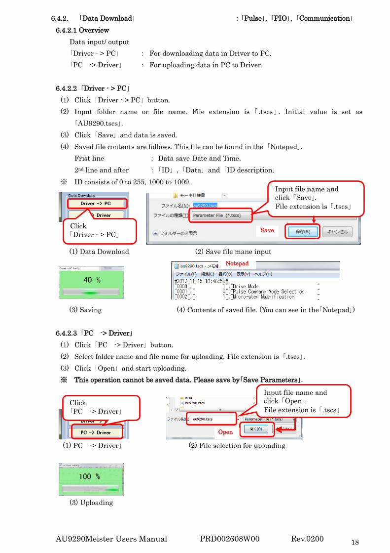
6.4.2. 「Data Download」 :「Pulse」, 「PIO」, 「Communication」 6.4.2.1 Overview Data input/ output 「Driver - > PC」 : For downloading data in Driver to PC. 「PC -> Driver」 : For uploading data in PC to Driver.
6.4.2.2 「Driver - > PC」
(1) Click 「Driver - > PC」 button. (2) Input folder name or file name. File extension is 「 .tscs 」 . Initial value is set as
「AU9290.tscs」. (3) Click 「Save」 and data is saved. (4) Saved file contents are follows. This file can be found in the 「Notepad」.
Frist line : Data save Date and Time. 2nd line and after : 「ID」 , 「Data」 and 「ID description」
※ ID consists of 0 to 255, 1000 to 1009.
(1) Data Download (2) Save file mane input
(3) Saving (4) Contents of saved file. (You can see in the「Notepad」) 6.4.2.3 「PC -> Driver」
(1) Click 「PC -> Driver」 button. (2) Select folder name and file name for uploading. File extension is 「.tscs」. (3) Click 「Open」 and start uploading. ※ This operation cannot be saved data. Please save by「Save Parameters」.
(1) PC -> Driver」 (2) File selection for uploading
(3) Uploading
Click 「Driver - > PC」
Input file name and click 「Save」. File extension is 「.tscs」
Save
Notepad
Click 「PC -> Driver」
Input file name and click 「Open」. File extension is 「.tscs」
Open

AU9290Meister Users Manual PRD002608W00 Rev.0200 19
6.4.3. 「Alarm History」 :「Pulse」, 「PIO」, 「Communication」 Alarm history indicated and erase.
6.4.3.1 「Alarm History Show」 (1) Click「Show」 button. (2) Alarm history indicated. (Total 32 times)
6.4.3.2 「Alarm History Clear」 (1) Click 「Clear」 button (2) Comment of「Alarm history erase?」comes , then select 「Yes」.※1 ※1 Before 「Alarm History Clear」,it recommends buck up 「Driver - > PC」.
After 「Alarm History Clear」,Automatically 「Alarm History」 is saved. It cannot be undone.
(1) Click 「Clear」 button (2) Message for confirmation
6.4.4. 「Drive Command」 :「Pulse」, 「PIO」, 「Communication」 Operation 「Drive Command」 is done to driver. Each bit of ID#60 is appled of each buttons
「Enable」 :Drive enable. 「Position Reset」 :Current position reset. 「Alarm Reset」 :Alarm reset. 「Origin Search」 :Origin search start (Refer to Users manual Chapter 10.7) ※In case 「PIO selection」(ID#7) is 「Origin Search is unavailable」, this is
not indicated. Refer to 6.5.10 「Origin Search」 in detail. 「IN_ Equiv.」 :Input equivalent PIO. Although it not indicated to 6.4.7 「I/O Status」. It becomes
「Drive Command」 equivalent to the state where the PIO signal is input. (Refer to Users manual Chapter 8)
Yes

AU9290Meister Users Manual PRD002608W00 Rev.0200 20
6.4.5. 「Drive Status」 :「Pulse」, 「PIO」, 「Communication」 Operation status is monitored. Each bit of ID#100 is appled of each label. It will be light by
below status. 「Drive On」 :At Drive On 「Ready」 :At Driver Ready 「In Position」 :When motor is targerd position. 「Alarm」 :At alarm 「Origin Set」 :When Origin Search operation is completed. 「Step-out」 :When Step-out is detected 「Over Voltage」 :When power voltage is at over voltage level. 「Power Down」 :When power voltage is at low voltage level. 「Over Heat」 :at Over-heat
「Drive Status」 「Over Load」 :At Over-load 「Current Ctrl Err」 :At Current control error 「Homing Fault」 :At Origin Search operation fault
6.4.6. 「Drive monitor」 :「Pulse」, 「PIO」, 「Communication」 Drive monitor is constantly monitored. 「I/O Status」 is refer to below.
「Drive monitor」
6.4.7. 「I/O Status」 :「PIO」,「Pulse」(Only Enable) (1) I/O input signal is indicated. Indication is dependent of 「Control mode」(ID#0). Control mode :In case of 「Position」, line 5 becomes 「SET」. :In case of 「Speed」, line 5 becomes 「IN4」. (2) When signal is input into I/O, 「Input Signal」 turn on. (Only for Nx1x) (3) I/O output sinal 「OUT1」 is indicated. Please refer detail setting to Users manual Chapter 8,
as status is dependent of 「Control mode」.
(1) In case of 「Position」 (1) In case of 「Speed」 (2) In case of 「I/O input」

AU9290Meister Users Manual PRD002608W00 Rev.0200 21
6.5. 「Parameters」 6.5.1. Contents in Subtab
Following is contents of each menu bar in the Sub tab. Detail is explained in each chapter later.
6.5.3 「Primary」 : Primary parameter settings and parameters processing. 6.5.4 「Basic Parameters」 : Parameter settings of basic operation and profile calculation 6.5.5 「PIO」 : Motor operation settings by parallel I/O. 6.5.6 「Communication」 : Motor operation settings by Communication. 6.5.7 「Alarm」 : Alarm settings. 6.5.8 「Motor」 : Motor settings. 6.5.9 「Driver」 : System parameter settings and current control loop gain settings. 6.5.10 「Origin Search」 : Parameter settings of Origin search operation. 6.5.2. Change parameters 6.5.2.1 Delete previous parameters
Frist, delete the previous parameter by one of the following two methods. Don't use 「Delete」 key while you change a value in a text box.
(1) Using 「Back space」 key and erase the previous parameter. (2) Drag the previous parameter.
The case of the method (1), the color of the frame will change.
(1) Using 「Back space」 Key (2) Dragging the previous parameter
6.5.2.2 Input new parameters When you input the new parameter, the color of the frame will change to light green. Don’t input a non-numeric data. If you input non-numeric data and press 「Enter」 key, an error message is displayed, changing parameter will be canceled.
「Error message」 If you click 「Enter」key, the color of the frame goes back to original state. It is indicating changing parameter is finished successfully.
6.5.2.3 Cancel parameters
If you click 「Esc」 key before 「Enter」 key, the color of the frame goes back to original state, and changing parameter is canceled.

AU9290Meister Users Manual PRD002608W00 Rev.0200 22
6.5.3. 「Primary」 :「Pulse」, 「PIO」, 「Communication」 6.5.3.1 「Primary」 Motor controlled by pulse. Please refer detail setting to Users manual Chapter 7.
「Drive Mode」 (ID#0) : Select 「Position」 or 「Speed」 「Pulse Command Mode Selection」 (ID#1) : Select the kind of command 「Micro-step Magnification」 (ID#2) : Set rotation angle per 1 pulse.
6.5.3.2 「Parameters processing」 Each button function 「Save Parameters」 :All parameter are saved in Non-volatile memory. 「Initialize Parameters」 :Common parameter is initialized ※
Attention:It may not be undone. Please operate the confirmation message on the check. ※ Before 「Initialize Parameters」, it recommends backup by 「Driver → PC (download)」.
After 「Initialize Parameters」, date is not saved. Please save by「Save Parameters」.
. Message for confirmation
6.5.4. 「Basic Parameters」 :「Pulse」, 「PIO」, 「Communication」 Set basic operation and profile calculation.
「Rotating Motor Current」 (ID#3) :Motor current during rotation. [%/ Rate current] 「Stopping Motor Current」 (ID#4) :Motor current during stopping. [%/ Rate current] 「Stop Detection Time」 (ID#5) :Time until Stop Status can be detected. [msec] 「PIO Input Filter」 (ID#6) :Set time og PIO input filter. [msec] 「Minimum Speed」 (ID#10) :Set minimum speed at Acc./Dec. on P-to-P. [rpm] 「Speed Limit」 (ID#11) :Limit of setting speed [rpm] 「Acceleration」 (ID#12) :Set acceleration on P-to-P operation. [rpm/sec] ※ 「Deceleration」 (ID#13) :Set deceleration on P-to-P operation. [rpm/sec] ※ ※ In software, value unit of 「Acceleration」 and 「Deceleration」is converted to [10rpm/sec].

AU9290Meister Users Manual PRD002608W00 Rev.0200 23
6.5.5. 「PIO」 :「PIO」 Motor operation is set by PIO (Parallel I/O). Display indication is different in each control
mode. (In case of Speed, PIO Control Parameters (Position) is not indicated.) Please refer detail setting to Users manual Chapter 8.
「Travel Speed-3「11」」 (ID#17) is also used as signal to start origin search in 6.5.10 「Origin Search」.
「Travel Speed -0~3」 (ID#14~17) :Travel speed set by PIO [rpm] 「Travel Command」-0~7 (ID#20~27) :Travel distance set by PIO [Pulse] 「Travel Magnification」 (ID#28) :Magnification of Travel distance
6.5.6. 「Communication」 :「Communication」 Motor operation is set by Serial communication. Please refer detail setting to Users manual
Chapter 9.
「Device ID」 (ID#30) :Device ID for serial communication. :1~15 selection 「Baud Rate」 (ID#31) :Baud rate of serial communication [kHz]※1 「UART Setting」 (ID#32) :Setting of serial communication ※2 「Communication Protocol」 (ID#33) :Select serial communication protocol ※3 ※1 In software, value unit of 「Baud Rate」is converted to [0.1kHz]. ※2 There are two ways to set. (1) input the figure or (2) select item and click 「Set」. Once click each item, below status shown. Then please click 「Cancel」 or 「Set」 after
changing. ※3 There are also two ways to set. (1) input the figure or (2) select item and click 「Set」.

AU9290Meister Users Manual PRD002608W00 Rev.0200 24
6.5.7. 「Alarm」 :「Pulse」, 「PIO」, 「Communication」 Change alarm settings.
「Over Voltage Detection Value」 (ID#36) :「6」Over-voltage alarm voltage setting. [V]※1 「Voltage Drop Detection Value」 (ID#37) :「7」Voltage drop alarm voltage setting. [V]※1 「Over-heat Detection Value」 (ID#38) :「5」Over-heart alarm temperature setting [℃]※1 「Current CtrlErr. Detection Value」(ID#39) :「3」current control error alarm setting [%/Rate current] 「Alarm mask」 (ID#35) :Each alarm is masked and ignored. ※2 ※1 In the software, following unit conversion is performed.
「Over Voltage Detection Value」and「Voltage Drop Detection Vlue」 :[0.1V] 「Over-heat Detection Value」 :[0.1℃] ※2 Following is the function of Alarm mask.
i.e.:Mask「Current Control Error」 No Mask : At alarm, 「Alarm」 the light turns on in Status, and turn off 「Drive On」.
(Due to 「Drive Off」, the light of 「Current Ctrl Err」 is turned off. Mask : At alarm, without turning on「Alarm」light, the light of 「Drive On」
remaining turned on, and motor can drive. (「Current Ctrl Err」is turned on.) Even if masked alarm occurred, it not records to alarm history.
No alarm mask Alarm mask

AU9290Meister Users Manual PRD002608W00 Rev.0200 25
6.5.8. 「Motor」 :「Pulse」, 「PIO」, 「Communication」 Motor operation settings. Please refer detail setting to Users manual Chapter 10.10.
「Motor Rate Current」 (ID#40) :Motor rated current [A]※ 「Winding Resistance」 (ID#41) :Motor winding resistance [Ω]※ 「Winding Inductance」 (ID#42) :Motor winding inductance [mH]※ 「Basic Number of Step」 (ID#44) :360 ÷ basic step angle (「Basic Step Angle」 :Moto basic step angle [dec] ) ※ In the software, following unit conversion is performed.
「Motor Rate Current」 :[0.01A] 「Winding Resistance」 :[0.01Ω] 「Winding Inductance」 :[0.01mH]
6.5.9. 「Diver」 6.5.9.1 「Systemm Parameters (can’t be changed)」 :「Pulse」, 「PIO」, 「Communication」 System parameter set in Driver is indicated. Each parameter can’t be changed. (This parameter is fixed in the Driver. Even if each value
is changed at the display, these values are not updated in Driver.)
「Current Scale」 (ID#50) [A/FS]※ 「Driver Rate Current」 (ID#51) [A]※ 「Driver Maximum Current」 (ID#52) [A]※ 「Voltage Scale」 (ID#53) [V/FS]※ 「Driver Type」 (ID#54) 「Product Code」 (ID#56) 「Software Code」 (ID#57) 「Revision」 (ID#58) ※ In the software, following unit conversion is performed. 「Current Scale」 [0.01A/FS] 「Driver Rata Current」 and 「Driver Maximum Current」 [0.01A] 「Voltage Scale」 [0.1V/FS]

AU9290Meister Users Manual PRD002608W00 Rev.0200 26
6.5.9.2 「Driver Parameters」 :「Pulse」, 「PIO」, 「Communication」 Current gain set in Driver is indicated. Usually, there is no need to change. Please change as necessary.
「Kcp」 (ID#48) :Current control loop proportional gain [rad/sec] 「Kci」 (ID#49) :Current control loop integral gain [rad/sec]
6.5.10. 「Origin Search」 :「Pulse」, 「PIO」, 「Communication」 Origin search operation is set. Please refer detail setting to Users manual Chapter 10.7.
「PIO Selection」 (ID#7) :Select origin serch opearion and enable-signal polarity. ※ 「Homing Velocity」 (Set by parameter of 「Travel speed-3「11」」) (ID#17) :Start origin search with this speed. [rpm] 「Creep Velocity」 (Set by parameter of 「Minimum speed」) (ID#10) :Creep speed in origin search operation. [rpm] 「Origin Stop Time」 (ID#18) :Stop time at origin in origin search operation [ms] ※ There are two ways to set.
(1) Input the value, refer to Users manual Table10.1 (2) Select items and click 「Set」.
When 「How to make Origin Search」 is not 「disable」, 「Polarity of Origin Signal」and 「Homing Direction」 is visible (see below). Select items and click 「Set」 or 「Cancel」.
(3) When 「How to make Origin Search」 is not 「disable」, 「Origin Search」 button is shown
at 6.4.4「Drive Command」. Origin search operation start to click 「Origin Search」 button after 「Drive On」.

AU9290Meister Users Manual PRD002608W00 Rev.0200 27
6.6. 「Debug 」 :「Pulse」, 「PIO」, 「Communication」 Data is confirmed with Debug.
When each ID is selected, the ID data and 「Content」 are indicated.
Operation procedure is as follows. 6.6.1 ID input There are two ways to input. 6.6.1.1 ID input:Use 「ID Ref」(Click) 6.6.1.2 ID input:Directly input 6.6.2 Change date (parameters) 6.6.3 Cancel and Initialize
6.6.1. ID input 6.6.1.1 ID input:Use 「ID Ref」 button When 「ID Ref」 is clicked, following window comes up. (Any line is applicable) Please click 「ID」 or 「Content」 you want to confirm.
(i.e.) In case of 「40」 or 「Motor Rate Current」 is clicked. (Any line is applicable)
Color of the line is changes and data is indicated.

AU9290Meister Users Manual PRD002608W00 Rev.0200 28
6.6.1.2 ID input: Directly input (1) On inputting 「ID」, the color of line is changed. (Any line is applicable)
(2) After inputting 「ID」, click 「Enter」, and then data is indicated.
6.6.2. Change data (parameters) 「Data」 is changed by Decimal or Hexadecimal. Attention:Pay attention to unit of value. 「Data」 indicates the date in Driver. In below case, 「Acceleration」 is 5000 [rpm/sec] (500 [10rpm/sec]).
(1) For value delete, delete by「Back-Space」key. Do not use「Delete」key.
(Dragging the previous parameter is applicable. Refer to 6.5.2 Change parameters)
(2) After changing data, please click 「Enter」. The color of the frame goes back to original
state, and value is updated.
Note: Even if 「System Parameter」 ID (for example 「Product Code」(ID#56) is changed,
The value is not updated and the color of the frame goes back to original state.

AU9290Meister Users Manual PRD002608W00 Rev.0200 29
6.6.3. Cancel and Initialize 6.6.3.1 Data cancel
(1) Please click 「Cancel」 button on the lower right bottom for input cancellation.
(2) The change parameter is canceled and the color of the frame goes back to original state.
6.6.3.2 ID cancel (1) Cancellation of ID is same. Please click 「Cancel」.
(2) The change ID is canceled and the color of the frame goes back to original state.
6.6.3.3 Initialize (1) To delete the line, please click 「Back-Space」 key at 「ID」.
(2) The color of the frame goes back to initial state.
(3) Indicated content is kept even after program is finished.

AU9290Meister Users Manual PRD002608W00 Rev.0200 30
6.7. 「Trial Operation」:「Pulse」, 「PIO」, 「Communication」 Trial run and origin search operation setting is shown below.
6.7.1. 「Trial Operation」 Operate motor in reference of the Users manual Chapter 6. (1) Set 6.5.8 「Motor」. (Main tab is 「Parameters」) (2) After motor settings, click 「Save Parameters」 and save to Non-volatile memory. (3) Change the Main tab to 「Trial Operation」. Following display is indicated.
(4) If it’s necessary, please set follows.
「Rotating Motor Current」 (ID#3) :Motor current during rotation. [%/Rate current] 「Stopping Motor Current」 (ID#4) :Motor current during stopping. [%/Rate current] 「Acceleration」 (ID#12) :Set acceleration on P-to-P operation. [rpm/sec]※ 「Deceleration」 (ID#13) :Set deceleration on P-to-P operation. [rpm/sec]※
※ In the software, value unit of Acceleration and Deceleration is converted to [10rpm/sec]. (5) Decide each values of 「Mode」, 「Speed」 and 「Distance」.
「Mode」 :Select「Position」 or 「Speed」. (Default:「Position」) 「Speed」 :Input rotation speed. (Default:100[rpm]) 「Distance」 :Input rotating distance. (Default:1[rev.]) In case of 「Speed」, this is unnecessary. ※Since the color will change when changing the value, click 「Enter」 key to confirm. (6) Click 「Start」 button, motor start to rotate. Rotation is stopped by following condition.
・In case of 「Position」, rotated the value in 「Distance」. ・In case of 「Position」 or 「Velocity」, click 「Stop」 button. (7) It is possible to change 「Speed」 and 「Distance」 during motor rotating. Also, if a negative
value input, motor rotate in the opposite direction. (Please pay attention to large change of value.)

AU9290Meister Users Manual PRD002608W00 Rev.0200 31
6.7.2. 「Origin Search trial」 Setting and trial of origin search. Please refer detail setting to Users manual Chapter 10.7.
「PIO Selection」 (ID#7) :Select origin serch opearion and enable-signal polarity. ※ 「Homing Velocity」 (Set by parameter of 「Travel speed-3「11」」) (ID#17) :Start origin search with this speed. [rpm] 「Creep Velocity」 (Set by parameter of 「Minimum speed」) (ID#10) :Creep speed in origin search operation. [rpm] 「Origin Stop Time」 (ID#18) :Stop time at origin in origin search operation [ms] ※ There are two ways to set. (1) Input the value, refer to Users manual Table10.1 (2) Select items and click 「Set」.
When 「How to make Origin Search」 is not 「disable」, 「Polarity of Origin Signal」and 「Homing Direction」 is visible (see below). Select items and click 「Set」 or 「Cancel」.
(3) When 「How to make Origin Search」 is not 「disable」, 「Start」and 「Stop」 button is shown at next to PIO selection.(see below) Click「Start」 button, 「Drive On」 and 「Origin Search」 is started.

AU9290Meister Users Manual PRD002608W00 Rev.0200 32
7. Trouble shooting Please refer in case Driver cannot operate correctly. Firstly, in case of trouble, please check the power input and cable connection. Other troubles are listed as below.
7.1. Trouble shooting related to USB port. Chapter Trouble Cause Treatment
3.1 No software for PC. Please get (download) from https://www.tamagawa-seiki.com/downloads/soft/
3.2 Device driver can’t be installed.
①Does the USB port set for other function specifically like Virtual Port?
①Please install with another USB port.
3.2 Device manager doesn’t indicate the port.
①USB Driver software set at Chapter 3.1 has installed correctly?
①Please install the USB Driver software.
7.2. Trouble shooting related to 「The Meister for AU9290」
Chapter Trouble Cause Treatment 4.(2) Error is generated. (1) 「.NET Framework 3.5」
not installed. (1) Please try Chapter 8. If use Windows7 or older, please
contact sales department. 4.(3) No initial display.
(No error indicated) (1) Display is hidden. (1) Please click icon blinking on Task
Bar. 4.(6) No restart software (1) No COM Port (1) Please try Chapter 3. 5.2.1 6.3.1
No COM port confirmed Chapter 3.3
(1) No power input to driver. (2) No USB connection.
(1) Please turn on power for Driver. (2) Please connect USB. Click 「Port Search」 and reconfirm
the connection. Ref. Chapter 6.3.2 5. 6.
「Invalid Data」
(1) Do not enter a non-numeric data?
(2) When performing 「PC->Driver」, is it not wrong data in upload file?
(1) Other characters than number is input in ID?
(2) Confirm the file to Upload.
5. 6.
「Number is overflow」
(1) Input number is larger or smaller against applicable value range?
(1) Valid value is 32bit in ID 1000 and above. (within ±2,147,483,647)
Other ID is 16bit. (within ±32767)
5. 6.
「Invalid Data IDxx」
(1) Negative number is input in ID and the parameter saved by 「SaveParameters」?
(1) Correct value in the ID No. indicated as error. (Indicated in message window), and click 「SaveParameters」 again.
If alarm comes up again, repeat to input correct values until error disappear.
6.
「Prease input number」
(1) Do not enter a non-numeric in ID?
(1) Only number is acceptable in ID.
Above trouble shooting is not covering perfectly. Please free to contact our sales department if you have any question and problem.
AU9290Meister Users Manual PRD002608W00 Rev.0200 33
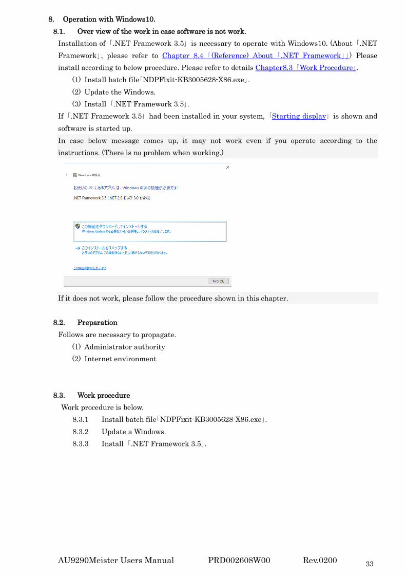
8. Operation with Windows10. 8.1. Over view of the work in case software is not work.
Installation of 「.NET Framework 3.5」 is necessary to operate with Windows10. (About 「.NET Framework」, please refer to Chapter 8.4 「(Reference) About 「.NET Framework」」) Please install according to below procedure. Please refer to details Chapter8.3 「Work Procedure」.
(1) Install batch file「NDPFixit-KB3005628-X86.exe」. (2) Update the Windows. (3) Install 「.NET Framework 3.5」.
If 「.NET Framework 3.5」 had been installed in your system, 「Starting display」 is shown and software is started up. In case below message comes up, it may not work even if you operate according to the instructions. (There is no problem when working.)
If it does not work, please follow the procedure shown in this chapter.
8.2. Preparation Follows are necessary to propagate.
(1) Administrator authority (2) Internet environment
8.3. Work procedure Work procedure is below.
8.3.1 Install batch file「NDPFixit-KB3005628-X86.exe」. 8.3.2 Update a Windows. 8.3.3 Install 「.NET Framework 3.5」.
AU9290Meister Users Manual PRD002608W00 Rev.0200 34
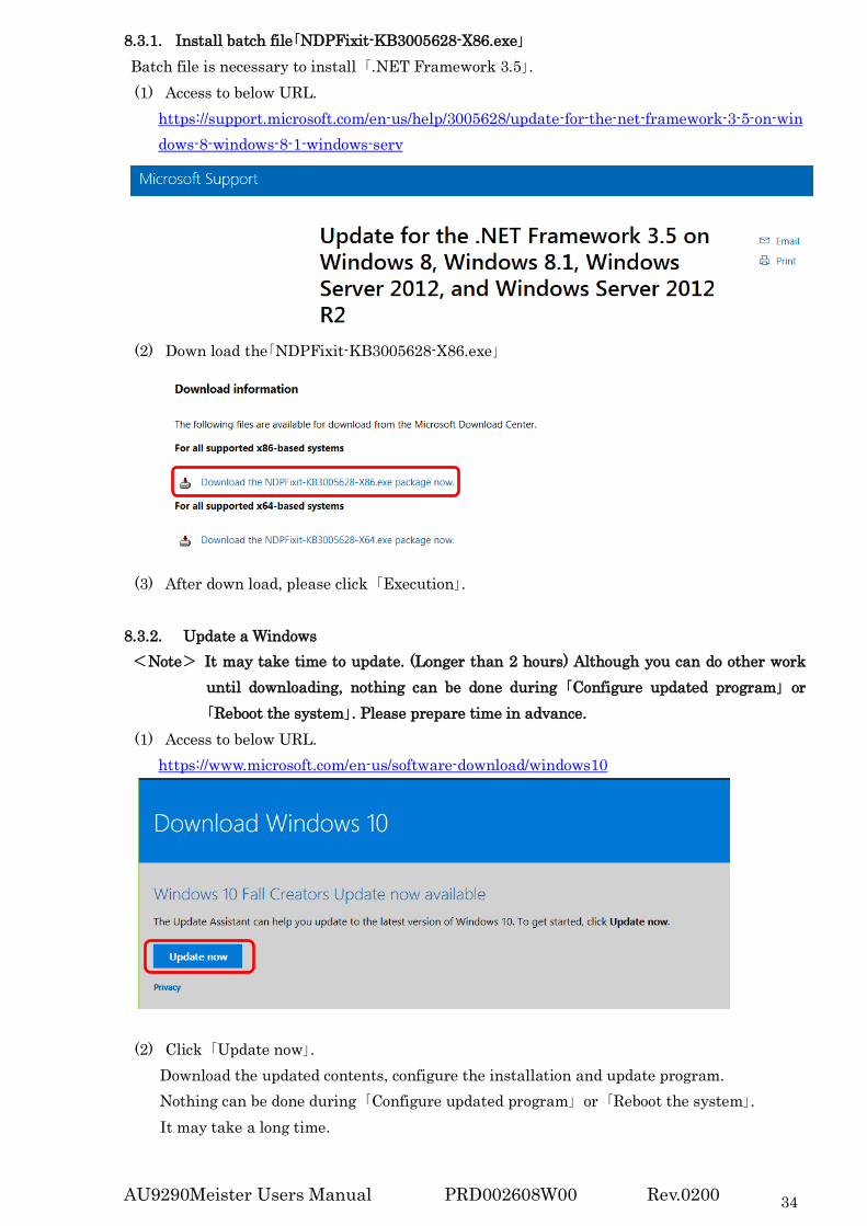
8.3.1. Install batch file「NDPFixit-KB3005628-X86.exe」 Batch file is necessary to install 「.NET Framework 3.5」. (1) Access to below URL.
https://support.microsoft.com/en-us/help/3005628/update-for-the-net-framework-3-5-on-windows-8-windows-8-1-windows-serv
(2) Down load the「NDPFixit-KB3005628-X86.exe」
(3) After down load, please click 「Execution」. 8.3.2. Update a Windows <Note> It may take time to update. (Longer than 2 hours) Although you can do other work
until downloading, nothing can be done during 「Configure updated program」 or 「Reboot the system」. Please prepare time in advance.
(1) Access to below URL. https://www.microsoft.com/en-us/software-download/windows10
(2) Click 「Update now」. Download the updated contents, configure the installation and update program. Nothing can be done during 「Configure updated program」 or 「Reboot the system」. It may take a long time.

AU9290Meister Users Manual PRD002608W00 Rev.0200 35
8.3.3. Install 「.NET Framework 3.5」 (1) Access to below URL. https://www.microsoft.com/en-us/download/details.aspx?id=22
(2) Click「Download」. After download, perform installation. (3) The Window 「Function of Windows」 open, and installation procedure for 「 .NET
Framework 3.5」 are displayed. Then, select 「Download this function and install」. ※ 「Download」 in (2) is only installer downloading. So, next downloading the program
from the installer.
(4) Install after download, and then work is completed.
8.4. (Reference) About 「.NET Framework」 This chapter explains 「.NET Framework」 very briefly. (You can skip this.) ・Necessary to use 「.NET Framework」 compliant application, for example 「Visual Basic
2010」 (「The Meister for AU9290」 is made by 「Visual Basic 2010」). ・In Windows 10 and Windows 8, version 「.NET Framework 4.x」 is pre-installed. (「.NET
Framework 3.5」) is not installed.) ・In Windows7, 「.NET Framework 3.5」 is pre-installed. ☆「.NET Framework 3.5」 is upwardly compatible with Version2.0 and 3.0, but completely
different software from 「.NET Framework 4.x」. By reason of 「☆」, 「The Meister for AU9290」 cannot be use in Windows 10 (and Windows 8). Version can be confirmed by searching 「Enable or disable Windows function」.
Download this function and install

AU9290Meister Users Manual PRD002608W00 Rev.0200 36
Revision history Date Revised content Note
2016. 4.20 First edition Rev.0000 2016. 4.26 Add description of total number of pages. Rev.0001 2018. 3.21 Full review with software version change (ver.311):
・Changing the software name ・Adding Windows10 operation manual ・Updating the screen display ・Describe where software provided (with link).
Rev.0200