The influences of temperature and microstructure on the ...
13
The influences of temperature and microstructure on the tensile properties of a CoCrFeMnNi high-entropy alloy F. Otto a,b,⇑ , A. Dlouhy ´ c , Ch. Somsen d , H. Bei a , G. Eggeler d , E.P. George a,b a Materials Science and Technology Division, Oak Ridge National Laboratory, Oak Ridge, TN 37831, USA b Materials Science and Engineering Department, University of Tennessee, Knoxville, TN 37996, USA c Institute of Physics of Materials, Academy of Sciences of the Czech Republic, 616 62 Brno, Czech Republic d Institut fuer Werkstoffe, Ruhr-Universitaet Bochum, 44780 Bochum, Germany Received 23 March 2013; received in revised form 11 June 2013; accepted 12 June 2013 Abstract An equiatomic CoCrFeMnNi high-entropy alloy, which crystallizes in the face-centered cubic (fcc) crystal structure, was produced by arc melting and drop casting. The drop-cast ingots were homogenized, cold rolled and recrystallized to obtain single-phase microstruc- tures with three different grain sizes in the range 4–160 lm. Quasi-static tensile tests at an engineering strain rate of 10 3 s 1 were then performed at temperatures between 77 and 1073 K. Yield strength, ultimate tensile strength and elongation to fracture all increased with decreasing temperature. During the initial stages of plasticity (up to 2% strain), deformation occurs by planar dislocation glide on the normal fcc slip system, {1 1 1}h110i, at all the temperatures and grain sizes investigated. Undissociated 1/2h110i dislocations were observed, as were numerous stacking faults, which imply the dissociation of several of these dislocations into 1/6h112i Shockley partials. At later stages (20% strain), nanoscale deformation twins were observed after interrupted tests at 77 K, but not in specimens tested at room temperature, where plasticity occurred exclusively by the aforementioned dislocations which organized into cells. Deformation twinning, by continually introducing new interfaces and decreasing the mean free path of dislocations during tensile testing (“dynamic Hall–Petch”), produces a high degree of work hardening and a significant increase in the ultimate tensile strength. This increased work hardening prevents the early onset of necking instability and is a reason for the enhanced ductility observed at 77 K. A second reason is that twinning can provide an additional deformation mode to accommodate plasticity. However, twinning cannot explain the increase in yield strength with decreasing temperature in our high-entropy alloy since it was not observed in the early stages of plastic deformation. Since strong temperature dependencies of yield strength are also seen in binary fcc solid solution alloys, it may be an inherent solute effect, which needs further study. Ó 2013 Acta Materialia Inc. Published by Elsevier Ltd. All rights reserved. Keywords: High-entropy alloys; Mechanical properties; Deformation twinning; Yield strength; Temperature dependence 1. Introduction Solid solution alloys consisting of multiple principal ele- ments in approximately equiatomic concentrations have been the subject of a rapidly increasing body of research since Yeh et al. [1] defined this new class of metallic alloys, now commonly referred to as high-entropy alloys. A solid solution alloy consisting of five or more elements in equi- atomic proportions is intriguing because of its potential for solid solution hardening (high strength) combined with good ductility if the solid solution phase possesses a simple crystal structure, e.g. face-centered cubic (fcc), with a large number of slip systems. Since high strength and ductility are important for structural materials, research efforts have tended to be application driven and directed towards find- ing new alloy compositions with promising mechanical properties. Numerous equiatomic multi-component alloys 1359-6454/$36.00 Ó 2013 Acta Materialia Inc. Published by Elsevier Ltd. All rights reserved. http://dx.doi.org/10.1016/j.actamat.2013.06.018 ⇑ Corresponding author at: Materials Science and Technology Division, Oak Ridge National Laboratory, Oak Ridge, TN 37831, USA. Tel.: +1 865 574 6917; fax: +1 865 576 6298. E-mail address: [email protected] (F. Otto). www.elsevier.com/locate/actamat Available online at www.sciencedirect.com Acta Materialia xxx (2013) xxx–xxx Please cite this article in press as: Otto F et al. The influences of temperature and microstructure on the tensile properties of a CoC- rFeMnNi high-entropy alloy. Acta Mater (2013), http://dx.doi.org/10.1016/j.actamat.2013.06.018
Transcript of The influences of temperature and microstructure on the ...
Available online at www.sciencedirect.com
www.elsevier.com/locate/actamat
Acta Materialia xxx (2013) xxx–xxx
The influences of temperature and microstructureon the tensile properties of a CoCrFeMnNi high-entropy alloy
F. Otto a,b,⇑, A. Dlouhy c, Ch. Somsen d, H. Bei a, G. Eggeler d, E.P. George a,b
a Materials Science and Technology Division, Oak Ridge National Laboratory, Oak Ridge, TN 37831, USAb Materials Science and Engineering Department, University of Tennessee, Knoxville, TN 37996, USA
c Institute of Physics of Materials, Academy of Sciences of the Czech Republic, 616 62 Brno, Czech Republicd Institut fuer Werkstoffe, Ruhr-Universitaet Bochum, 44780 Bochum, Germany
Received 23 March 2013; received in revised form 11 June 2013; accepted 12 June 2013
Abstract
An equiatomic CoCrFeMnNi high-entropy alloy, which crystallizes in the face-centered cubic (fcc) crystal structure, was produced byarc melting and drop casting. The drop-cast ingots were homogenized, cold rolled and recrystallized to obtain single-phase microstruc-tures with three different grain sizes in the range 4–160 lm. Quasi-static tensile tests at an engineering strain rate of 10�3 s�1 were thenperformed at temperatures between 77 and 1073 K. Yield strength, ultimate tensile strength and elongation to fracture all increased withdecreasing temperature. During the initial stages of plasticity (up to �2% strain), deformation occurs by planar dislocation glide on thenormal fcc slip system, {111}h110i, at all the temperatures and grain sizes investigated. Undissociated 1/2h110i dislocations wereobserved, as were numerous stacking faults, which imply the dissociation of several of these dislocations into 1/6h112i Shockley partials.At later stages (�20% strain), nanoscale deformation twins were observed after interrupted tests at 77 K, but not in specimens tested atroom temperature, where plasticity occurred exclusively by the aforementioned dislocations which organized into cells. Deformationtwinning, by continually introducing new interfaces and decreasing the mean free path of dislocations during tensile testing (“dynamicHall–Petch”), produces a high degree of work hardening and a significant increase in the ultimate tensile strength. This increased workhardening prevents the early onset of necking instability and is a reason for the enhanced ductility observed at 77 K. A second reason isthat twinning can provide an additional deformation mode to accommodate plasticity. However, twinning cannot explain the increase inyield strength with decreasing temperature in our high-entropy alloy since it was not observed in the early stages of plastic deformation.Since strong temperature dependencies of yield strength are also seen in binary fcc solid solution alloys, it may be an inherent soluteeffect, which needs further study.� 2013 Acta Materialia Inc. Published by Elsevier Ltd. All rights reserved.
Keywords: High-entropy alloys; Mechanical properties; Deformation twinning; Yield strength; Temperature dependence
1. Introduction
Solid solution alloys consisting of multiple principal ele-ments in approximately equiatomic concentrations havebeen the subject of a rapidly increasing body of researchsince Yeh et al. [1] defined this new class of metallic alloys,
1359-6454/$36.00 � 2013 Acta Materialia Inc. Published by Elsevier Ltd. All
http://dx.doi.org/10.1016/j.actamat.2013.06.018
⇑ Corresponding author at: Materials Science and Technology Division,Oak Ridge National Laboratory, Oak Ridge, TN 37831, USA. Tel.: +1865 574 6917; fax: +1 865 576 6298.
E-mail address: [email protected] (F. Otto).
Please cite this article in press as: Otto F et al. The influences of temrFeMnNi high-entropy alloy. Acta Mater (2013), http://dx.doi.org/1
now commonly referred to as high-entropy alloys. A solidsolution alloy consisting of five or more elements in equi-atomic proportions is intriguing because of its potentialfor solid solution hardening (high strength) combined withgood ductility if the solid solution phase possesses a simplecrystal structure, e.g. face-centered cubic (fcc), with a largenumber of slip systems. Since high strength and ductilityare important for structural materials, research efforts havetended to be application driven and directed towards find-ing new alloy compositions with promising mechanicalproperties. Numerous equiatomic multi-component alloys
rights reserved.
perature and microstructure on the tensile properties of a CoC-0.1016/j.actamat.2013.06.018
2 F. Otto et al. / Acta Materialia xxx (2013) xxx–xxx
have been reported in the literature and some mechanicalproperties have been assessed with mixed results (e.g. [2–12]). Despite this considerable effort, little is known con-cerning the basic deformation mechanisms in this class ofalloys due to the following main reasons.
Most of the equiatomic alloys described in the literaturedo not consist of a single solid solution phase; instead, theycontain multiple phases, including secondary solid solutionphases and/or intermetallic compounds [6–10]. Thus, themeasured mechanical properties, all obtained in compres-sion, represent composite responses of the multiphasemicrostructures. This might be sufficient for a roughscreening of candidates with promising mechanical proper-ties, but it is difficult to develop a fundamental understand-ing based on such studies, e.g. the extent and mechanismsof solution hardening in high-entropy alloys. Additionally,interesting aspects of their basic mechanical propertiesmight be obscured by the presence of secondary phases.
In a few cases where single-phase solid solution alloyswere successfully produced and mechanically tested[11,12], no efforts were made to break down the cast micro-structure by thermomechanical treatment. This may bepartially due to the fact that these alloys consisted ofrefractory metals with high melting points which are brittleat low homologous temperatures and therefore difficult toprocess [11,12]. Regardless, the measured compressivemechanical properties were influenced by the coarse, heter-ogeneous grain structure and chemical gradients (segrega-tion) in the microstructure as a result of the dendriticsolidification during casting.
There have been two studies of rolled and recrystallizedsingle-phase high-entropy alloys: one in which room-tem-perature hardness was investigated as a function of grainsize [13] and the other in which preliminary tensile tests wereperformed at different temperatures [14]. However, therehave been no efforts to investigate the nature of dislocationsthat operate in these alloys. If atoms are randomlydistributed in a solid solution high-entropy alloy, the atomicenvironment around dislocations varies constantly as theymove through the material. For an interpretation of themechanical properties of high-entropy alloys, it is thereforemandatory to study dislocation plasticity in more detail.
In the present study, we address these shortcomings byinvestigating an equiatomic five-element CoCrFeMnNialloy that was first reported by Cantor et al. [15]. It hasbeen shown that this alloy consists of a single fcc solid solu-tion phase exhibiting a high degree of thermodynamic sta-bility [16] and excellent malleability [14]. Processing tobreak down the cast structure is possible by conventionalmethods such as rolling followed by recovery and recrystal-lization [13,14]. Gali and George [14] conducted an initialassessment of the tensile properties of the alloy being inves-tigated here, as well as a related medium-entropy alloy,CoCrFeNi, both of which they thermomechanically pro-cessed by hot rolling.
Our goal here was to perform a detailed study of themechanical properties of the CoCrFeMnNi high-entropy
Please cite this article in press as: Otto F et al. The influences of temrFeMnNi high-entropy alloy. Acta Mater (2013), http://dx.doi.org/1
alloy with special focus on the influence of temperatureand microstructure. We present results from quasi-statictensile tests for three different grain sizes (4.4, 50 and155 lm) and test temperatures between 77 and 1073 K.Wherever possible, the mechanical properties are relatedto the deformation mechanisms uncovered by transmissionelectron microscopy (TEM).
2. Material and methods
2.1. Experimental methods
Rectangular ingots (127 � 25.4 � 12.7 mm3) of the equi-atomic CoCrFeMnNi alloy weighing �475 g were pro-duced by arc melting and drop casting under pure Aratmosphere. The purity of each of the raw materials wasat least 99.9%. Since Mn rapidly oxidizes in air, the Mnstock was cleaned in an aqueous solution of nitric acidimmediately before it was added to the other materials inthe arc melter. Additionally, because Mn has a high vaporpressure [17], it was stacked between the other constituentsto minimize evaporation. Nevertheless, we found that therewas weight loss during arc melting and an additional gramof Mn had to be added per ingot to compensate for itsevaporation. After the raw materials were loaded in thearc melter, the chamber was first evacuated to �7 � 10�4
Pa and then backfilled with Ar gas to a pressure of�8.4 � 104 Pa. Before the high-entropy alloy was melted,a small piece of Zr was melted to getter any residual oxygenthat might be present in the chamber. The arc-melted but-tons were flipped and remelted five times to promotehomogeneity and thorough mixing of the elements beforethey were dropped into the rectangular Cu mold.
The drop-cast ingots were cleaned in an aqueous solu-tion of hydrochloric acid and hydrogen peroxide, encapsu-lated in evacuated quartz ampules and solution-annealedfor 48 h at 1473 K. The ingots were subsequently coldrolled along the longitudinal ingot direction to sheets hav-ing a final thickness of �1.7 mm. Starting from their initialthickness of 12.7 mm, this corresponds to a reduction inthickness of �87%. A few cross-rolling steps were intro-duced in between to increase the width of the rolled sheetsto approximately 40 mm. The rolled sheets were annealedfor 1 h at 1073, 1273 or 1423 K to obtain fully recrystal-lized microstructures with three different grain sizes. The1423 K anneal was conducted in an evacuated quartz cap-sule; the other two anneals were conducted in air resultingin only minor surface oxidation.
Flat dog-bone-shaped tensile specimens with a gaugelength of 12.7 mm were machined from the recrystallizedsheets by electric discharge machining with their longitudi-nal axes perpendicular to the rolling direction of the sheet.The tensile specimens were ground carefully on each sidewith SiC paper, resulting in a final specimen thickness of1.6 mm and a gauge section width of 3.14 mm. Vickersmicrohardness indents (300 g load) were made at the endsof the gauge section to enable the measurement of strain
perature and microstructure on the tensile properties of a CoC-0.1016/j.actamat.2013.06.018
F. Otto et al. / Acta Materialia xxx (2013) xxx–xxx 3
by means of an optical traveling microscope. Tensile testswere performed at an engineering strain rate of 10�3 s�1
in a screw-driven Instron 4204 test rig. Two tests were per-formed for each material state at temperatures of 77, 293,473, 673, 873 and 1073 K. Tests at room temperature andabove were conducted in air. For tests at 77 K, the speci-men and grips were immersed in a liquid nitrogen bathfor about 10–15 min before the start of the test and stayedcompletely submerged during the test. For all temperaturesabove room temperature, the sample was brought to tem-perature by radiative/convective heat transfer from aninduction-heated stainless steel susceptor. Once the desiredtest temperature was reached, the sample was held there for15–30 min before the start of the test.
To investigate the evolution of microstructure withaccumulated strain, additional tensile specimens weredeformed at test temperatures of 77, 293 and 873 K, andthe tests were interrupted at various strain levels. Thinsheets with a thickness of about 300 lm were carefullyextracted from their gauge sections by electric dischargemachining and ground down to foils having a thicknessof about 100–120 lm using fine SiC paper. Discs with adiameter of 3 mm were punched out of the foils and elec-tron transparent regions were produced in a twin jet polish-ing system using an aqueous electrolyte containing 21%acetic acid at a temperature of 15 �C and an applied volt-age of 20 V. TEM investigations were conducted in anFEI Tecnai G2 SuperTwin and a Philips CM20 microscopeoperated at 200 kV. Scanning electron microscopy investi-gations were conducted in a JEOL 6500F microscopeequipped with a field emission gun operated at 15 kV.
3. Results
3.1. Initial microstructures
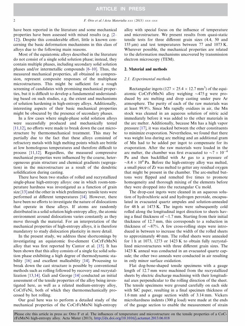
Figs. 1 and 2 show the microstructures of CoCrFeMnNisheets after cold rolling and annealing. The backscatteredelectron micrographs of Fig. 1, taken along the three prin-cipal sheet directions, RD (rolling direction), ND (normal
Fig. 1. Backscattered electron images of the microstructures of the CoCrFeMn1 h anneals at: (a) 1073 K, grain size 4.4 lm; (b) 1273 K, grain size 50 lm; an
Please cite this article in press as: Otto F et al. The influences of temrFeMnNi high-entropy alloy. Acta Mater (2013), http://dx.doi.org/1
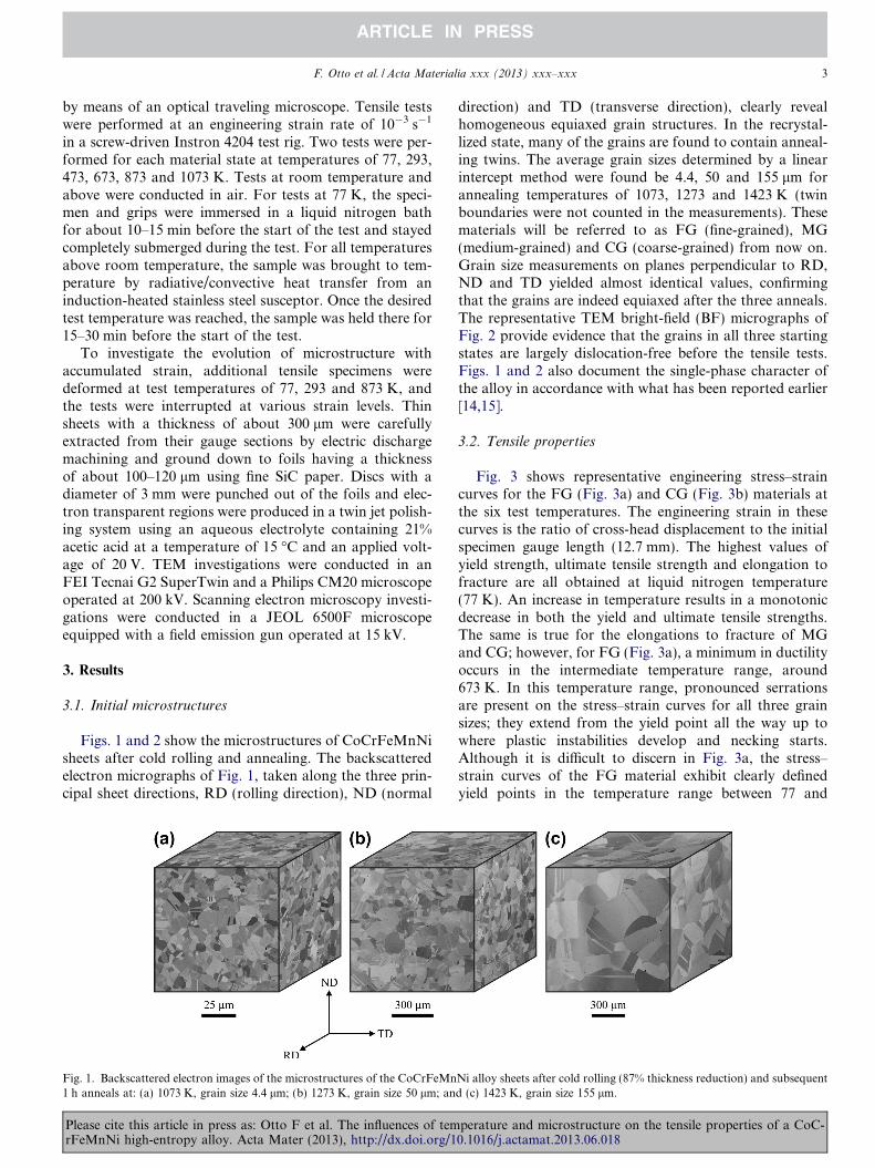
direction) and TD (transverse direction), clearly revealhomogeneous equiaxed grain structures. In the recrystal-lized state, many of the grains are found to contain anneal-ing twins. The average grain sizes determined by a linearintercept method were found be 4.4, 50 and 155 lm forannealing temperatures of 1073, 1273 and 1423 K (twinboundaries were not counted in the measurements). Thesematerials will be referred to as FG (fine-grained), MG(medium-grained) and CG (coarse-grained) from now on.Grain size measurements on planes perpendicular to RD,ND and TD yielded almost identical values, confirmingthat the grains are indeed equiaxed after the three anneals.The representative TEM bright-field (BF) micrographs ofFig. 2 provide evidence that the grains in all three startingstates are largely dislocation-free before the tensile tests.Figs. 1 and 2 also document the single-phase character ofthe alloy in accordance with what has been reported earlier[14,15].
3.2. Tensile properties
Fig. 3 shows representative engineering stress–straincurves for the FG (Fig. 3a) and CG (Fig. 3b) materials atthe six test temperatures. The engineering strain in thesecurves is the ratio of cross-head displacement to the initialspecimen gauge length (12.7 mm). The highest values ofyield strength, ultimate tensile strength and elongation tofracture are all obtained at liquid nitrogen temperature(77 K). An increase in temperature results in a monotonicdecrease in both the yield and ultimate tensile strengths.The same is true for the elongations to fracture of MGand CG; however, for FG (Fig. 3a), a minimum in ductilityoccurs in the intermediate temperature range, around673 K. In this temperature range, pronounced serrationsare present on the stress–strain curves for all three grainsizes; they extend from the yield point all the way up towhere plastic instabilities develop and necking starts.Although it is difficult to discern in Fig. 3a, the stress–strain curves of the FG material exhibit clearly definedyield points in the temperature range between 77 and
Ni alloy sheets after cold rolling (87% thickness reduction) and subsequentd (c) 1423 K, grain size 155 lm.
perature and microstructure on the tensile properties of a CoC-0.1016/j.actamat.2013.06.018
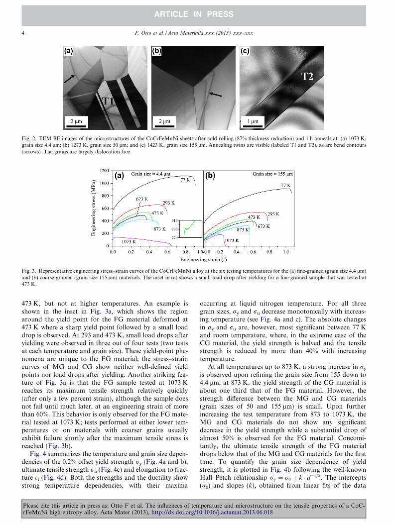
Fig. 2. TEM BF images of the microstructures of the CoCrFeMnNi sheets after cold rolling (87% thickness reduction) and 1 h anneals at: (a) 1073 K,grain size 4.4 lm; (b) 1273 K, grain size 50 lm; and (c) 1423 K, grain size 155 lm. Annealing twins are visible (labeled T1 and T2), as are bend contours(arrows). The grains are largely dislocation-free.
Fig. 3. Representative engineering stress–strain curves of the CoCrFeMnNi alloy at the six testing temperatures for the (a) fine-grained (grain size 4.4 lm)and (b) coarse-grained (grain size 155 lm) materials. The inset in (a) shows a small load drop after yielding for a fine-grained sample that was tested at473 K.
4 F. Otto et al. / Acta Materialia xxx (2013) xxx–xxx
473 K, but not at higher temperatures. An example isshown in the inset in Fig. 3a, which shows the regionaround the yield point for the FG material deformed at473 K where a sharp yield point followed by a small loaddrop is observed. At 293 and 473 K, small load drops afteryielding were observed in three out of four tests (two testsat each temperature and grain size). These yield-point phe-nomena are unique to the FG material; the stress–straincurves of MG and CG show neither well-defined yieldpoints nor load drops after yielding. Another striking fea-ture of Fig. 3a is that the FG sample tested at 1073 Kreaches its maximum tensile strength relatively quickly(after only a few percent strain), although the sample doesnot fail until much later, at an engineering strain of morethan 60%. This behavior is only observed for the FG mate-rial tested at 1073 K; tests performed at either lower tem-peratures or on materials with coarser grains usuallyexhibit failure shortly after the maximum tensile stress isreached (Fig. 3b).
Fig. 4 summarizes the temperature and grain size depen-dencies of the 0.2% offset yield strength ry (Fig. 4a and b),ultimate tensile strength ru (Fig. 4c) and elongation to frac-ture ef (Fig. 4d). Both the strengths and the ductility showstrong temperature dependencies, with their maxima
Please cite this article in press as: Otto F et al. The influences of temrFeMnNi high-entropy alloy. Acta Mater (2013), http://dx.doi.org/1
occurring at liquid nitrogen temperature. For all threegrain sizes, ry and ru decrease monotonically with increas-ing temperature (see Fig. 4a and c). The absolute changesin ry and ru are, however, most significant between 77 Kand room temperature, where, in the extreme case of theCG material, the yield strength is halved and the tensilestrength is reduced by more than 40% with increasingtemperature.
At all temperatures up to 873 K, a strong increase in ry
is observed upon refining the grain size from 155 down to4.4 lm; at 873 K, the yield strength of the CG material isabout one third that of the FG material. However, thestrength difference between the MG and CG materials(grain sizes of 50 and 155 lm) is small. Upon furtherincreasing the test temperature from 873 to 1073 K, theMG and CG materials do not show any significantdecrease in the yield strength while a substantial drop ofalmost 50% is observed for the FG material. Concomi-tantly, the ultimate tensile strength of the FG materialdrops below that of the MG and CG materials for the firsttime. To quantify the grain size dependence of yieldstrength, it is plotted in Fig. 4b following the well-knownHall–Petch relationship ry ¼ r0 þ k � d�1=2. The intercepts(r0) and slopes (k), obtained from linear fits of the data
perature and microstructure on the tensile properties of a CoC-0.1016/j.actamat.2013.06.018
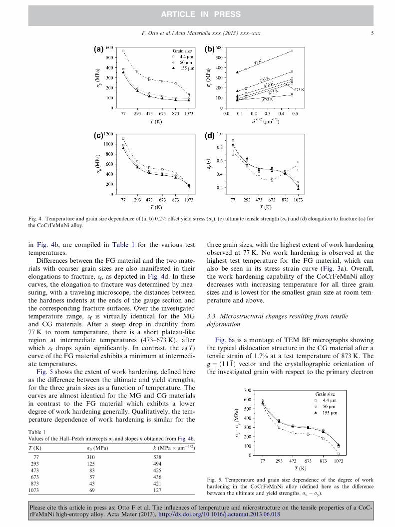
Fig. 4. Temperature and grain size dependence of (a, b) 0.2% offset yield stress (ry), (c) ultimate tensile strength (ru) and (d) elongation to fracture (ef) forthe CoCrFeMnNi alloy.
F. Otto et al. / Acta Materialia xxx (2013) xxx–xxx 5
in Fig. 4b, are compiled in Table 1 for the various testtemperatures.
Differences between the FG material and the two mate-rials with coarser grain sizes are also manifested in theirelongations to fracture, ef, as depicted in Fig. 4d. In thesecurves, the elongation to fracture was determined by mea-suring, with a traveling microscope, the distances betweenthe hardness indents at the ends of the gauge section andthe corresponding fracture surfaces. Over the investigatedtemperature range, ef is virtually identical for the MGand CG materials. After a steep drop in ductility from77 K to room temperature, there is a short plateau-likeregion at intermediate temperatures (473–673 K), afterwhich ef drops again significantly. In contrast, the ef(T)curve of the FG material exhibits a minimum at intermedi-ate temperatures.
Fig. 5 shows the extent of work hardening, defined hereas the difference between the ultimate and yield strengths,for the three grain sizes as a function of temperature. Thecurves are almost identical for the MG and CG materialsin contrast to the FG material which exhibits a lowerdegree of work hardening generally. Qualitatively, the tem-perature dependence of work hardening is similar for the
Table 1Values of the Hall–Petch intercepts r0 and slopes k obtained from Fig. 4b.
T (K) r0 (MPa) k (MPa � lm�1/2)
77 310 538293 125 494473 83 425673 57 436873 43 421
1073 69 127
Please cite this article in press as: Otto F et al. The influences of temrFeMnNi high-entropy alloy. Acta Mater (2013), http://dx.doi.org/1
three grain sizes, with the highest extent of work hardeningobserved at 77 K. No work hardening is observed at thehighest test temperature for the FG material, which canalso be seen in its stress–strain curve (Fig. 3a). Overall,the work hardening capability of the CoCrFeMnNi alloydecreases with increasing temperature for all three grainsizes and is lowest for the smallest grain size at room tem-perature and above.
3.3. Microstructural changes resulting from tensile
deformation
Fig. 6a is a montage of TEM BF micrographs showingthe typical dislocation structure in the CG material after atensile strain of 1.7% at a test temperature of 873 K. Theg ¼ ð11�1Þ vector and the crystallographic orientation ofthe investigated grain with respect to the primary electron
Fig. 5. Temperature and grain size dependence of the degree of workhardening in the CoCrFeMnNi alloy (defined here as the differencebetween the ultimate and yield strengths, ru � ry).
perature and microstructure on the tensile properties of a CoC-0.1016/j.actamat.2013.06.018
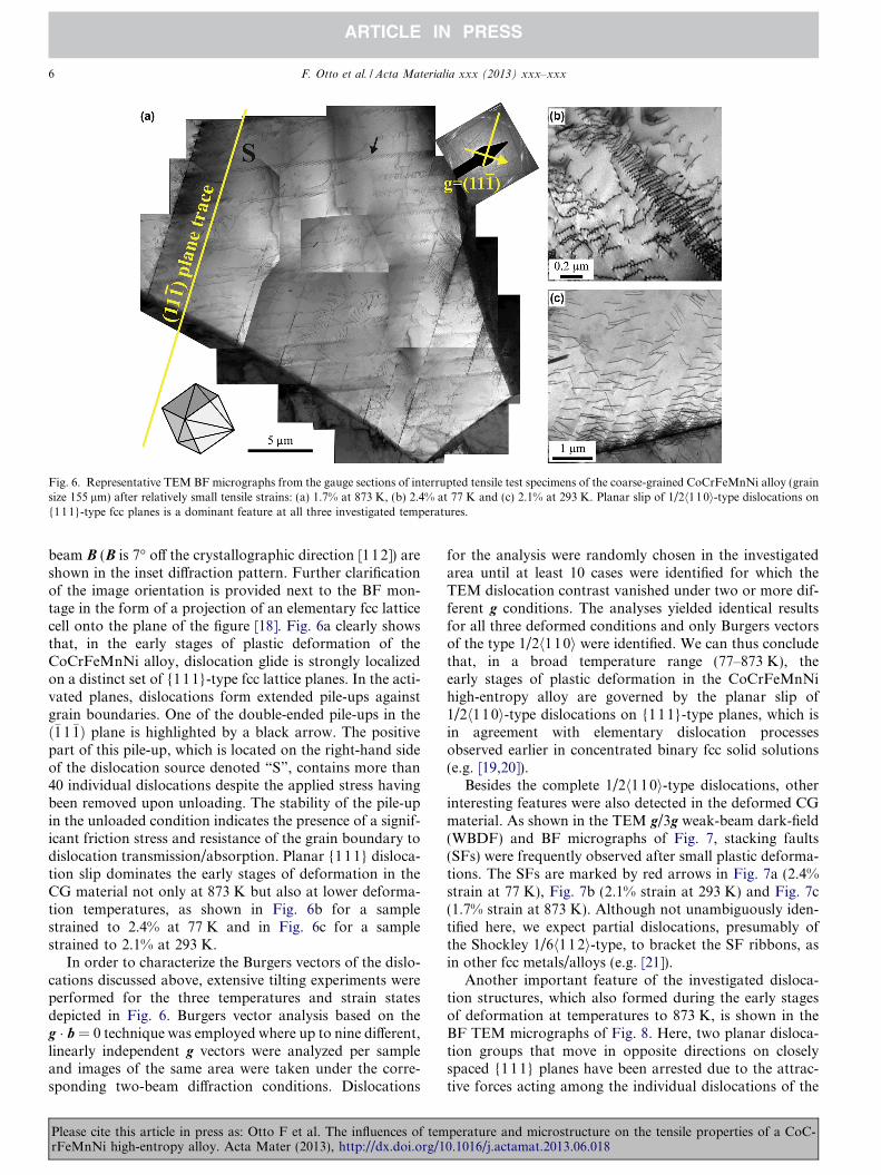
Fig. 6. Representative TEM BF micrographs from the gauge sections of interrupted tensile test specimens of the coarse-grained CoCrFeMnNi alloy (grainsize 155 lm) after relatively small tensile strains: (a) 1.7% at 873 K, (b) 2.4% at 77 K and (c) 2.1% at 293 K. Planar slip of 1/2h110i-type dislocations on{111}-type fcc planes is a dominant feature at all three investigated temperatures.
6 F. Otto et al. / Acta Materialia xxx (2013) xxx–xxx
beam B (B is 7� off the crystallographic direction [112]) areshown in the inset diffraction pattern. Further clarificationof the image orientation is provided next to the BF mon-tage in the form of a projection of an elementary fcc latticecell onto the plane of the figure [18]. Fig. 6a clearly showsthat, in the early stages of plastic deformation of theCoCrFeMnNi alloy, dislocation glide is strongly localizedon a distinct set of {111}-type fcc lattice planes. In the acti-vated planes, dislocations form extended pile-ups againstgrain boundaries. One of the double-ended pile-ups in theð�11�1Þ plane is highlighted by a black arrow. The positivepart of this pile-up, which is located on the right-hand sideof the dislocation source denoted “S”, contains more than40 individual dislocations despite the applied stress havingbeen removed upon unloading. The stability of the pile-upin the unloaded condition indicates the presence of a signif-icant friction stress and resistance of the grain boundary todislocation transmission/absorption. Planar {111} disloca-tion slip dominates the early stages of deformation in theCG material not only at 873 K but also at lower deforma-tion temperatures, as shown in Fig. 6b for a samplestrained to 2.4% at 77 K and in Fig. 6c for a samplestrained to 2.1% at 293 K.
In order to characterize the Burgers vectors of the dislo-cations discussed above, extensive tilting experiments wereperformed for the three temperatures and strain statesdepicted in Fig. 6. Burgers vector analysis based on theg � b = 0 technique was employed where up to nine different,linearly independent g vectors were analyzed per sampleand images of the same area were taken under the corre-sponding two-beam diffraction conditions. Dislocations
Please cite this article in press as: Otto F et al. The influences of temrFeMnNi high-entropy alloy. Acta Mater (2013), http://dx.doi.org/1
for the analysis were randomly chosen in the investigatedarea until at least 10 cases were identified for which theTEM dislocation contrast vanished under two or more dif-ferent g conditions. The analyses yielded identical resultsfor all three deformed conditions and only Burgers vectorsof the type 1/2h110i were identified. We can thus concludethat, in a broad temperature range (77–873 K), theearly stages of plastic deformation in the CoCrFeMnNihigh-entropy alloy are governed by the planar slip of1/2h110i-type dislocations on {111}-type planes, which isin agreement with elementary dislocation processesobserved earlier in concentrated binary fcc solid solutions(e.g. [19,20]).
Besides the complete 1/2h110i-type dislocations, otherinteresting features were also detected in the deformed CGmaterial. As shown in the TEM g/3g weak-beam dark-field(WBDF) and BF micrographs of Fig. 7, stacking faults(SFs) were frequently observed after small plastic deforma-tions. The SFs are marked by red arrows in Fig. 7a (2.4%strain at 77 K), Fig. 7b (2.1% strain at 293 K) and Fig. 7c(1.7% strain at 873 K). Although not unambiguously iden-tified here, we expect partial dislocations, presumably ofthe Shockley 1/6h1 12i-type, to bracket the SF ribbons, asin other fcc metals/alloys (e.g. [21]).
Another important feature of the investigated disloca-tion structures, which also formed during the early stagesof deformation at temperatures to 873 K, is shown in theBF TEM micrographs of Fig. 8. Here, two planar disloca-tion groups that move in opposite directions on closelyspaced {111} planes have been arrested due to the attrac-tive forces acting among the individual dislocations of the
perature and microstructure on the tensile properties of a CoC-0.1016/j.actamat.2013.06.018
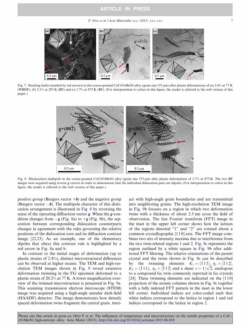
Fig. 7. Stacking faults (marked by red arrows) in the coarse-grained CoCrFeMnNi alloy (grain size 155 lm) after plastic deformations of (a) 2.4% at 77 K(WBDF), (b) 2.1% at 293 K (BF) and (c) 1.7% at 873 K (BF). (For interpretation to colors in this figure, the reader is referred to the web version of thispaper.)
Fig. 8. Disclocation multipole in the coarse-grained CoCrFeMnNi alloy (grain size 155 lm) after plastic deformation of 1.7% at 873 K. The two BFimages were acquired using reverse g vectors in order to demonstrate that the individual dislocation pairs are dipoles. (For interpretation to colors in thisfigure, the reader is referred to the web version of this paper.)
F. Otto et al. / Acta Materialia xxx (2013) xxx–xxx 7
positive group (Burgers vector +b) and the negative group(Burgers vector �b). The multipole character of this dislo-cation arrangement is illustrated in Fig. 8 by reversing thesense of the operating diffraction vector g. When the g-con-dition changes from �g (Fig. 8a) to +g (Fig. 8b), the sep-aration between corresponding dislocation counterpartschanges in agreement with the rules governing the relativepositions of the dislocation core and its diffraction contrastimage [22,23]. As an example, one of the elementarydipoles that obeys this contrast rule is highlighted by ared arrow in Fig. 8a and b.
In contrast to the initial stages of deformation (up toplastic strains of 2.4%), distinct microstructural differencescan be observed at higher strains. The TEM and high-res-olution TEM images shown in Fig. 9 reveal extensivedeformation twinning in the FG specimen deformed to aplastic strain of 20.2% at 77 K. A lower magnification over-view of the twinned microstructure is presented in Fig. 9a.This scanning transmission electron microscope (STEM)image was acquired using a high-angle annular dark-field(HAADF) detector. The image demonstrates how denselyspaced deformation twins fragment the central grain, inter-
Please cite this article in press as: Otto F et al. The influences of temrFeMnNi high-entropy alloy. Acta Mater (2013), http://dx.doi.org/1
act with high-angle grain boundaries and are transmittedinto neighboring grains. The high-resolution TEM imagein Fig. 9b focuses on a region in which two deformationtwins with a thickness of about 2.5 nm cross the field ofobservation. The fast Fourier transform (FFT) image inthe inset in the upper left corner shows how the latticesof the regions denoted “1” and “2” are rotated about acommon crystallographic [110] axis. The FFT image com-bines two sets of intensity maxima due to interference fromthe two twin-related regions 1 and 2. Fig. 9c represents theregion outlined by a white square in Fig. 9b after addi-tional FFT filtering. The relative orientations of the parentcrystal and the twins shown in Fig. 9c can be describedby the twinning elements K1 ¼ ð�11�1Þ; g1 ¼ ½�1 12�;K2 ¼ ð�111Þ; g2 ¼ ½�11�2� and a shear s ¼ 1=
ffiffiffi
2p
, analogousto a compound fcc twin commonly reported in fcc crystals[24]. These twinning elements are indicated on the [110]projection of the atomic columns shown in Fig. 9c togetherwith a fully indexed FFT pattern in the inset in the lowerleft corner. Individual indices are color-coded such thatwhite indices correspond to the lattice in region 1 and redindices correspond to the lattice in region 2.
perature and microstructure on the tensile properties of a CoC-0.1016/j.actamat.2013.06.018
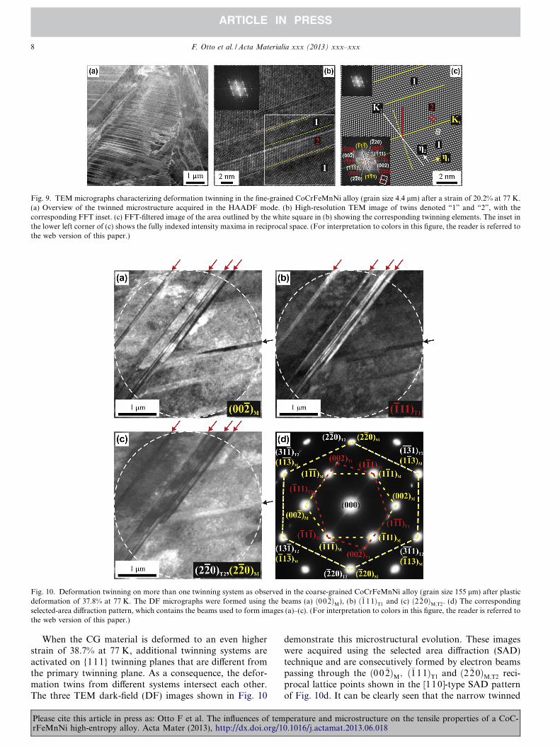
Fig. 9. TEM micrographs characterizing deformation twinning in the fine-grained CoCrFeMnNi alloy (grain size 4.4 lm) after a strain of 20.2% at 77 K.(a) Overview of the twinned microstructure acquired in the HAADF mode. (b) High-resolution TEM image of twins denoted “1” and “2”, with thecorresponding FFT inset. (c) FFT-filtered image of the area outlined by the white square in (b) showing the corresponding twinning elements. The inset inthe lower left corner of (c) shows the fully indexed intensity maxima in reciprocal space. (For interpretation to colors in this figure, the reader is referred tothe web version of this paper.)
Fig. 10. Deformation twinning on more than one twinning system as observed in the coarse-grained CoCrFeMnNi alloy (grain size 155 lm) after plasticdeformation of 37.8% at 77 K. The DF micrographs were formed using the beams (a) ð00�2ÞM), (b) ð�111ÞT1 and (c) ð2�20ÞM;T2. (d) The correspondingselected-area diffraction pattern, which contains the beams used to form images (a)–(c). (For interpretation to colors in this figure, the reader is referred tothe web version of this paper.)
8 F. Otto et al. / Acta Materialia xxx (2013) xxx–xxx
When the CG material is deformed to an even higherstrain of 38.7% at 77 K, additional twinning systems areactivated on {111} twinning planes that are different fromthe primary twinning plane. As a consequence, the defor-mation twins from different systems intersect each other.The three TEM dark-field (DF) images shown in Fig. 10
Please cite this article in press as: Otto F et al. The influences of temrFeMnNi high-entropy alloy. Acta Mater (2013), http://dx.doi.org/1
demonstrate this microstructural evolution. These imageswere acquired using the selected area diffraction (SAD)technique and are consecutively formed by electron beamspassing through the ð0 0�2ÞM; ð�111ÞT1 and ð2�20ÞM;T2 reci-procal lattice points shown in the [110]-type SAD patternof Fig. 10d. It can be clearly seen that the narrow twinned
perature and microstructure on the tensile properties of a CoC-0.1016/j.actamat.2013.06.018
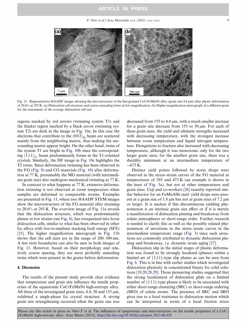
Fig. 11. Representative HAADF images showing the microstructure of the fine-grained CoCrFeMnNi alloy (grain size 4.4 lm) after plastic deformationof 20.6% at 293 K. (a) Dislocation cell structure and coarse annealing twins at low magnification. (b) Higher magnification micrograph of a different grainfor the assessment of the average dislocation cell size.
F. Otto et al. / Acta Materialia xxx (2013) xxx–xxx 9
regions marked by red arrows (twinning system T1) andthe thicker region marked by a black arrow (twinning sys-tem T2) are dark in the image in Fig. 10a. In this case theelectrons that contribute to the ð00�2ÞM beam are scatteredmainly from the neighboring matrix, thus making the sur-rounding matrix appear bright. On the other hand, twins ofthe system T1 are bright in Fig. 10b since the correspond-ing ð�111ÞT1 beam predominantly forms in the T1-orientedcrystals. Similarly, the DF image in Fig. 10c highlights theT2 twins. Since deformation twinning has been observed inthe FG (Fig. 9) and CG materials (Fig. 10) after deforma-tion at 77 K, presumably the MG material (with intermedi-ate grain size) also undergoes mechanical twinning at 77 K.
In contrast to what happens at 77 K, extensive deforma-tion twinning is not observed at room temperature whensamples are deformed to comparable strains. Examplesare presented in Fig. 11, where two HAADF STEM imagesshow the microstructure of the FG material after strainingto 20.6% at 293 K. The overview image of Fig. 11a revealsthat the dislocation structure, which was predominantlyplanar at low strains (see Fig. 6), has reorganized into loosedislocation cells, similar to what has been observed in otherfcc alloys with low-to-medium stacking fault energy (SFE)[25]. The higher magnification micrograph in Fig. 11bshows that the cell sizes are in the range of 200–300 nm.A few twin boundaries can also be seen in both images ofFig. 11. However, based on their morphology and rela-tively coarse spacing, they are most probably annealingtwins which were present in the grains before deformation.
4. Discussion
The results of the present study provide clear evidencethat temperature and grain size influence the tensile prop-erties of the equiatomic CoCrFeMnNi high-entropy alloy.All three of the investigated grain sizes, 4.4, 50 and 155 lm,exhibited a single-phase fcc crystal structure. A stronggrain size strengthening occurred when the grain size was
Please cite this article in press as: Otto F et al. The influences of temrFeMnNi high-entropy alloy. Acta Mater (2013), http://dx.doi.org/1
decreased from 155 to 4.4 lm, with a much smaller increasefor a grain size decrease from 155 to 50 lm. For each ofthese grain sizes, the yield and ultimate strengths increasedwith decreasing temperature, with the strongest increasebetween room temperature and liquid nitrogen tempera-ture. Elongations to fracture also increased with decreasingtemperature, although it was monotonic only for the twolarger grain sizes; for the smallest grain size, there was aductility minimum at an intermediate temperature of�673 K.
Distinct yield points followed by stress drops wereobserved in the stress–strain curves of the FG material attemperatures of 293 and 473 K (an example is shown inthe inset of Fig. 3a), but not at other temperatures andgrain sizes. Ueji and co-workers [26] recently reported sim-ilar behavior for an FeMnAlSi steel: yield drops were pres-ent at a grain size of 1.8 lm but not at grain sizes of 7.2 lmor larger. It is unclear if this discontinuous yielding phe-nomenon is an intrinsic grain size effect or if it is merelya manifestation of dislocation pinning and breakaway fromsolute atmospheres or short-range order. Further researchis needed to clarify this as well as the possibly related phe-nomenon of serrations in the stress–strain curves in theintermediate temperature range (Fig. 3) since such serra-tions are commonly attributed to dynamic dislocation pin-ning and breakaway, i.e. dynamic strain aging [27].
Dislocation slip in the initial stages of plastic deforma-tion was found to be strongly localized (planar) within alimited set of {111}-type slip planes as can be seen fromFig. 6. This is in line with earlier studies which investigateddislocation plasticity in concentrated binary fcc solid solu-tions [19,20,28,29]. Those pioneering studies suggested thatthe strong localization of dislocation glide on a limitednumber of {11 1}-type planes is likely to be associated witheither short-range clustering (SRC) or short-range ordering(SRO) of solute atoms. The presence of SRC and SROgives rise to a local resistance to dislocation motion whichcan be interpreted in terms of a local friction stress
perature and microstructure on the tensile properties of a CoC-0.1016/j.actamat.2013.06.018
10 F. Otto et al. / Acta Materialia xxx (2013) xxx–xxx
[19,20,28,29]. The authors argued that passage of a disloca-tion through a relatively ordered/clustered region on a slipplane randomizes the distribution of solute atoms and,consequently, decreases the friction stress opposing dislo-cation motion in that particular slip plane. This providesan easy plane for subsequent dislocations to move onand dislocation glide tends to organize into a distinct setof slip planes. Based on the experimental results presentedin this study, the above scenario proposed for concentratedbinary fcc solid solutions may be applicable also to theyielding region of our CoCrFeMnNi high-entropy alloy.Another possible reason for planar slip is the splitting of1/2h110i dislocations into 1/6h1 12i Shockley partials withstacking faults in between, which would tend to minimizecross slip and confine slip to the primary {111} planes.In support of this mechanism, numerous stacking faultswere indeed observed after deformation (Fig. 7), althoughundissociated (full) 1/2h110i dislocations were alsoobserved.
The dislocation structures observed after more advancedstages of deformation (plastic strains of 20% or higher) losetheir planar character as shown in Fig. 11. The transitionfrom planar slip at low strains to loosely organized disloca-tion cell structures at high strains may be assisted by thefollowing mechanism. As demonstrated in Fig. 8, disloca-tion multipoles form at relatively small tensile strains.These multipoles represent low-energy dislocation configu-rations and therefore considerably limit dislocation motionin the activated slip planes; they are thus an important con-tributor to dislocation hardening. When the initial slipplanes are blocked by this multipole arrangement, activityon fresh slip planes is required to accommodate the exter-nally imposed strain forcing dislocation plasticity to spreadout more uniformly. A more uniform distribution of slipevents results, in turn, in a more uniform destruction ofSRC and/or SRO and, consequently, the friction stress inthe affected material volumes. Therefore, planar slip van-ishes gradually and the dislocations tend to arrange in aform that is more commonly found at low temperaturesin pure fcc metals such as Cu [25].
Our study provides clear evidence that deformationtwinning contributes to the accumulated strain when theCoCrFeMnNi alloy is deformed at 77 K (Figs. 9 and 10).Considering the fcc twinning shear of s ¼ 1=
ffiffiffi
2p
, andassuming an average Taylor factor of M = 3.06 for a ran-domly textured material, twinning can account for a max-imum strain of 23%, provided that the twinned volume is100% of the total material; in reality, the strain that canbe accommodated by deformation twinning will likely bewell below this value. Despite this, the elongation to frac-ture increased by more than 20 percentage points (from�50–60% to �70–90%) when the test temperaturedecreased from 293 to 77 K. Therefore, there should beother reasons for the observed ductility increase, as dis-cussed below.
When the test temperature is decreased from 293 to77 K, a steep increase in the yield and the ultimate
Please cite this article in press as: Otto F et al. The influences of temrFeMnNi high-entropy alloy. Acta Mater (2013), http://dx.doi.org/1
strengths is observed for all three grain sizes, as shown inFig. 4. Although both of these mechanical properties varywith temperature in a qualitatively similar way, the abso-lute change is more pronounced for the ultimate tensilestrength due to increased work hardening at low tempera-tures, as illustrated in Fig. 5. This is accompanied by atransition from dislocation glide dominated plasticity atroom temperature to a mixed deformation mode consistingof dislocation glide plus nanoscale twinning at 77 K. Twin-ning is expected to contribute to the increased work hard-ening at 77 K, similar to what is seen in other materials,where mechanical twinning is a major deformation mode(e.g. [30–35]). Although the exact nature and magnitudeof twinning-induced strengthening is still a subject ofdebate in the literature, there seems to be general agree-ment that the formation of twins during mechanical testingresults in continuous grain fragmentation by the introduc-tion of new interfaces, which effectively reduces the disloca-tion mean free path and causes strengthening [34–38]. Thisis commonly referred to as the “dynamic Hall–Petch”
effect.The twinning-induced increase in work hardening at
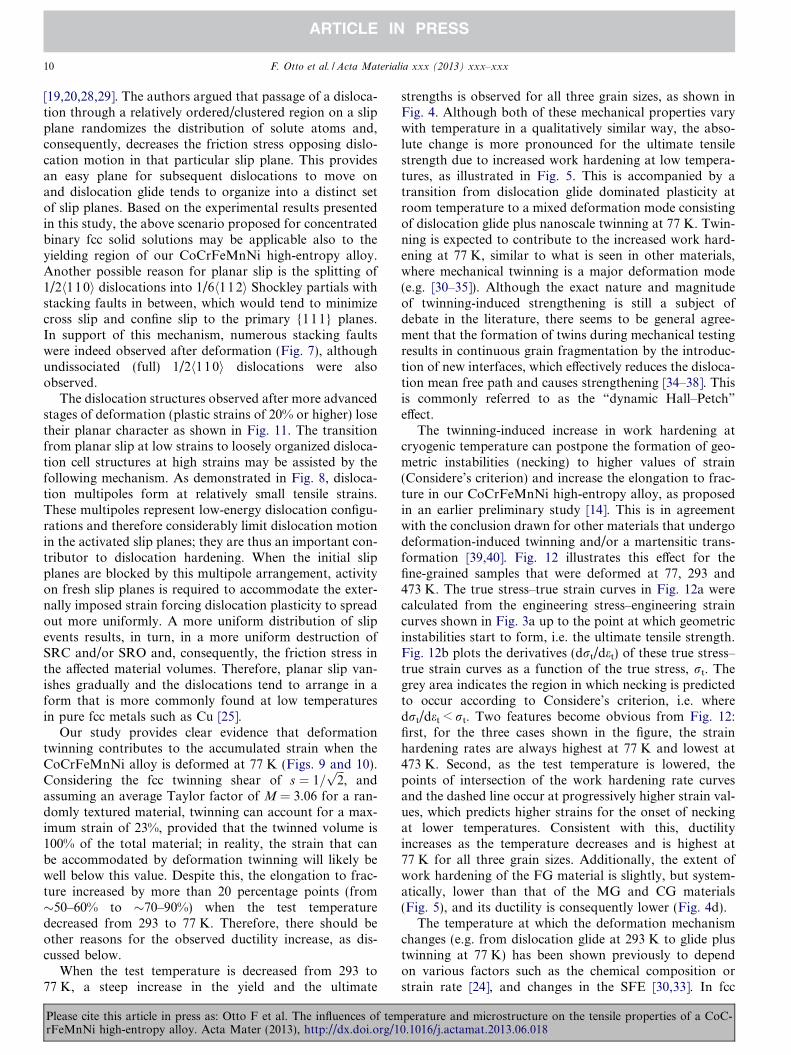
cryogenic temperature can postpone the formation of geo-metric instabilities (necking) to higher values of strain(Considere’s criterion) and increase the elongation to frac-ture in our CoCrFeMnNi high-entropy alloy, as proposedin an earlier preliminary study [14]. This is in agreementwith the conclusion drawn for other materials that undergodeformation-induced twinning and/or a martensitic trans-formation [39,40]. Fig. 12 illustrates this effect for thefine-grained samples that were deformed at 77, 293 and473 K. The true stress–true strain curves in Fig. 12a werecalculated from the engineering stress–engineering straincurves shown in Fig. 3a up to the point at which geometricinstabilities start to form, i.e. the ultimate tensile strength.Fig. 12b plots the derivatives (drt/det) of these true stress–true strain curves as a function of the true stress, rt. Thegrey area indicates the region in which necking is predictedto occur according to Considere’s criterion, i.e. wheredrt/det < rt. Two features become obvious from Fig. 12:first, for the three cases shown in the figure, the strainhardening rates are always highest at 77 K and lowest at473 K. Second, as the test temperature is lowered, thepoints of intersection of the work hardening rate curvesand the dashed line occur at progressively higher strain val-ues, which predicts higher strains for the onset of neckingat lower temperatures. Consistent with this, ductilityincreases as the temperature decreases and is highest at77 K for all three grain sizes. Additionally, the extent ofwork hardening of the FG material is slightly, but system-atically, lower than that of the MG and CG materials(Fig. 5), and its ductility is consequently lower (Fig. 4d).
The temperature at which the deformation mechanismchanges (e.g. from dislocation glide at 293 K to glide plustwinning at 77 K) has been shown previously to dependon various factors such as the chemical composition orstrain rate [24], and changes in the SFE [30,33]. In fcc
perature and microstructure on the tensile properties of a CoC-0.1016/j.actamat.2013.06.018
Fig. 12. (a) True stress–true strain curves calculated from the engineering stress–engineering strain curves (Fig. 3a) up to the point at which geometricinstabilities start to form, i.e. the ultimate tensile strength. (b) Work hardening rate (derivative of the true stress–true strain curves, drt/det) plotted as afunction of the true stress, rt, for fine-grained samples (grain size 4.4 lm) deformed at 77 K (black symbols), 293 K (red symbols) and 473 K (greensymbols). The grey area (underneath the dashed line) is where geometric instability (necking) is expected according to Considere’s criterion, i.e. where thework hardening rate is less than the true stress. (For interpretation to colors in this figure, the reader is referred to the web version of this paper.)
F. Otto et al. / Acta Materialia xxx (2013) xxx–xxx 11
alloys, low-to-medium SFEs (�18–45 mJ m�2) favor theformation of deformation twins [41], while an fcc! hexag-onal close-packed phase transformation can be observedwhen the SFE is even lower [42]. A rationale for this behav-ior is that both of these low SFE deformation processes arerelated to the dissociation of perfect dislocations intoShockley partials and thus to the formation of a stackingfault in between these partials. Idrissi et al. [43] recentlyprovided convincing microstructural evidence for the roleof intrinsic and extrinsic stacking faults as precursors forthe formation of deformation-induced twins and e-mar-tensite, respectively, in an interstitial-free FeMnAlSi alloy.Hence, if the SFE increases with temperature, the propen-sity for twinning or deformation-induced phase transfor-mations may be expected to decrease as well.
Unfortunately, for the CoCrFeMnNi high-entropy alloyinvestigated here, neither the SFE nor its temperaturedependence is known. The microstructural evidence pre-sented in Fig. 7, however, demonstrate that SFs can befound after deformation over the whole temperature rangeinvestigated. Moreover, no obvious change in the deformedmicrostructures is observed as a function of temperatureafter low plastic strains of about 2%, as shown in Fig. 6,where planar slip is identified to be the main deformationmechanism before the onset of twinning. Planar slip isexpected in low SFE materials [44] since the dissociationof dislocations makes cross slip more difficult. Therefore,neither observation supports the idea that a drastic increasein SFE with temperature is the main reason for why twin-ning disappears as a deformation mode at room tempera-ture and above in the CoCrFeMnNi alloy. Instead, itseems more plausible that this transition is related to thepronounced temperature dependence of the yield strength(Figs. 3 and 4). The data in Fig. 4c show that the ultimatetensile strength of the FG material (grain size, 4.4 lm) isaround 660 MPa at 293 K. When the test temperature isdecreased to 77 K, this stress is reached at a plastic strainof less than 5%. A detailed investigation of the twinningstress for the CoCrFeMnNi alloy has yet to be conducted,but Fig. 6 clearly shows that a certain degree of dislocation
Please cite this article in press as: Otto F et al. The influences of temrFeMnNi high-entropy alloy. Acta Mater (2013), http://dx.doi.org/1
plasticity precedes the onset of twinning since no deforma-tion twins were observed at strains less than 2.4% at 77 K.It is therefore conceivable that the stress that is needed toinduce deformation by twinning cannot be reached whenspecimens are deformed at room temperature even if otherintrinsic material properties such as the SFE remainedapproximately constant.
The strong temperature dependence of the yield stressobserved in the present high-entropy alloy between 77and 293 K is not typically seen in pure fcc metals. Asshown in Fig. 4a, the absolute differences in the yieldstrength between 77 and 293 K are almost independent ofgrain size, with values of 205, 194 and 185 MPa for theFG, MG and CG materials, respectively. The ry(T) curvesfor materials of different grain sizes are roughly parallel upto intermediate temperatures (873 K). As a consequence, itcan be inferred that the temperature dependence of theyield stress at low temperatures (below 873 K) is not influ-enced significantly by grain size. A refinement of the grainsize causes merely a vertical shift of the yield stress vs. tem-perature curves in Fig. 4a. For each of these curves, thetemperature-dependent yield strength, ry(T), can be viewedas the sum of thermal and athermal components [44,45]:
ryðT Þ ¼ rth þ rath; ð1Þwhere rth and rath are the thermal and athermal contribu-tions, respectively. Unlike in body-centered cubic metals,where the Peierls stress is significant, in pure fcc metalsrth is usually negligible, resulting in a temperature-indepen-dent yield strength [46]. However, it can be significant insome binary fcc solid solutions; most such studies havebeen performed on alloys where Cu is the solvent [47–53].In binary Cu–Al, Cu–Ge or Cu–Mn solid solution alloys,it has been shown that rth increases with increasing solutecontent [45,47]. Furthermore, the critical temperature (Tc)at which the yield strength transitions from being tempera-ture-dependent to being temperature-independent shifts tohigher temperatures with increasing solute concentrations.In dilute solutions, the energy barriers to dislocation mo-tion, since they can be overcome by thermal activation at
perature and microstructure on the tensile properties of a CoC-0.1016/j.actamat.2013.06.018
12 F. Otto et al. / Acta Materialia xxx (2013) xxx–xxx
relatively low temperatures, must be short-range obstacleson the order of a Burgers vector [49]. The obstacles in moreconcentrated solid solutions, like the present high-entropyalloy, must be stronger since they require greater thermalactivation to overcome. The nature of these obstacles, espe-cially in equiatomic high-entropy alloys where there aremultiple principal elements and, therefore, no “solute” or“solvent”, is an interesting topic for further study. Eventhe nature of a dislocation line, which is normally viewedas being made up of mostly the same kind of atom, needsre-evaluation in the case of a high-entropy solid solution al-loy that consists of multiple principal elements.
5. Summary and conclusions
An equiatomic CoCrFeMnNi high-entropy alloy wasproduced by arc melting, drop casting and rolling, afterwhich it was recrystallized to produce single-phase, fcc-structured, equiaxed microstructures with three differentgrain sizes, 4.4, 50 and 155 lm. The temperature and grainsize dependencies of its tensile properties were investigatedin the temperature range 77–1073 K. To interpret themechanical properties, microstructural analyses were per-formed by TEM before and after deformation. Based onour observations, the following conclusions can be drawn.
(1) Up to test temperatures of 873 K, yield strengthincreased with decreasing grain size, with the greatestincrease occurring when the grain size was decreasedfrom 155 to 4.4 lm and only a modest increase occur-ring when it was decreased from 155 to 50 lm. Ulti-mate tensile strength also increased with decreasinggrain size, though to a lesser extent than yieldstrength. Elongation to fracture was comparable forthe two coarser grain sizes and lower for the finergrain size material.
(2) For all three grain sizes, the alloy shows a strongincrease in yield and ultimate tensile strengths withdecreasing temperature. Elongation to fracture alsoincreased with decreasing temperature, monotoni-cally for the two coarser grains, but with an interme-diate temperature minimum at around 673 K for thefine-grained material.
(3) In the temperature range of 77–873 K, initial plastic-ity, up to tensile strains of about 2%, occurs exclu-sively by planar glide of 1/2h110i dislocations on{111} planes. Stacking faults were observedconsistent with splitting of these dislocations into1/6h112i Shockley partials. Planar slip could be theresult of the first dislocations to move on a slip plane,destroying short-range order or clustering and mak-ing it easier for the following dislocations to moveon the same slip plane. Stacking-fault-coupled partialdislocations could be another reason for planar slipby making cross slip harder. At higher strains, atroom temperature and above, slip became morehomogeneous and cell structures developed.
Please cite this article in press as: Otto F et al. The influences of temrFeMnNi high-entropy alloy. Acta Mater (2013), http://dx.doi.org/1
(4) Upon lowering the test temperature from room tem-perature to 77 K, nanoscale twinning was observed asan additional deformation mode in specimens inter-rupted after strains of 20% or more, but not in spec-imens interrupted shortly after yielding (strainsaround 2%). This deformation-induced twinning, byproviding an additional deformation mode, likelycontributes to the observed increase in ductility atlow temperatures. Additionally, twinning introducesextra interfaces within the grains during deformation(“dynamic Hall–Petch”); therefore, it increases thework hardening rate and the ultimate tensile strength.This increase in work hardening postpones the onsetof necking instability to higher strains (Considere’scriterion) and is another reason for the higher ductil-ity at 77 K compared to that at room temperature.
(5) The increase in yield strength with decreasing temper-ature seen in this fcc high-entropy alloy is not typi-cally observed in pure fcc metals. However, it isknown to occur in binary fcc solid solutions to vary-ing degrees, depending on the solute concentration.Our TEM analyses to date have not provided anexplanation for this temperature dependence of yieldstrength. Further studies are needed to shed light onthe thermally activated microstructural processes thatgovern yielding in equiatomic high-entropy solidsolution alloys in which the terms “solute” and “sol-vent” lose their conventional meanings.
Acknowledgements
This research was supported by the US Department ofEnergy, Basic Energy Sciences, Materials Sciences andEngineering Division. F.O. also received funding fromthe Alexander von Humboldt Foundation through a Feo-dor Lynen Research Fellowship. A.D. received financialsupport through the IPM AS CR development programno. RVO:68081723.
References
[1] Yeh JW, Chen SK, Lin SJ, Gan JY, Chin TS, Shun TT, et al. AdvEng Mater 2004;6:299.
[2] Cantor B, Audebert F, Galano M, Kim KB, Stone IC, Warren PJ. JMetastable Nanocryst Mater 2005;24–25:1.
[3] Cantor B. Ann Chim Sci Mater 2007;32:245.[4] Munitz A, Kaufman MJ, Chandler JP, Kalaantari H, Abbaschian R.
Mater Sci Eng A 2013;560:633.[5] Ng C, Guo S, Luan J, Shi S, Liu CT. Intermetallics 2012;31:165.[6] Liu L, Zhu JB, Zhang C, Li JC, Jiang Q. Mater Sci Eng A
2012;548:64.[7] Tong CJ, Chen MR, Chen SK, Yeh JW, Shun TT, Lin SJ, et al.
Metall Mater Trans A 2005;36:1263.[8] Wang XF, Zhang Y, Qiao Y, Chen GL. Intermetallics 2007;15:357.[9] Zhou YJ, Zhang Y, Wang YL, Chen GL. Mater Sci Eng A 2007;454–
455:260.[10] Zhu JM, Fu HM, Zhang HF, Wang AM, Li H, Hu ZQ. Mater Sci
Eng A 2010;527:6975.
perature and microstructure on the tensile properties of a CoC-0.1016/j.actamat.2013.06.018
F. Otto et al. / Acta Materialia xxx (2013) xxx–xxx 13
[11] Senkov ON, Wilks GB, Scott JM, Miracle DB. Intermetallics2011;19:698.
[12] Senkov ON, Scott JM, Senkova SV, Miracle DB, Woodward CF. JAlloys Compd 2011;2011:6043.
[13] Liu WH, Wu Y, He JY, Nieh TG, Lu ZP. Scripta Mater 2013;68:526.[14] Gali A, George EP. Intermetallics 2013;39:74.[15] Cantor B, Chang ITH, Knight P, Vincent AJB. Mater Sci Eng A
2004;375–377:213.[16] Otto F, Yang Y, Bei H, George EP. Acta Mater 2013;61:2628.[17] Loebel R. In: Weast RC, editor. Handbook of chemistry and
physics. Cleveland (OH): CRC Press; 1974.[18] Dlouhy A, Eggeler G. Pract Metallogr 1996;33:629.[19] Gerold V, Karnthaler HP. Acta Metall 1989;37:2177.[20] Neuhauser H. Acta Metall 1975;23:455.[21] Korner A, Karnthaler HP. Phys Status Solidi 1981;21:19.[22] Hirsch P, Howie A, Nicholson RB, Pashley DW, Whelan MJ.
Electron microscopy of thin crystals. Washington (DC): Butterworths;1965.
[23] Williams DB, Carter CB. Transmission electron microscopy Part 3:Imaging. 2nd ed. New York: Springer; 2009.
[24] Christian JW, Mahajan S. Prog Mater Sci 1995;39:1.[25] Landau P, Shneck RZ, Makov G, Venkert A. MRS Proc 2006;982.
0982-KK09-05.[26] Ueji R, Tsuchida N, Terada D, Tsuji N, Tanaka Y, Takemura A,
et al. Scripta Mater 2008;59:963.[27] Robinson JM, Shaw MP. Int Mater Rev 1994;39:113.[28] Olfe J, Neuhauser H. Phys Status Solidi A 1988;109:149.[29] Plessing J, Achmus Ch, Neuhauser H, Schonfeld B, Kostorz G. Z
Metallkd 1997;88:630.[30] Remy L, Pineau A. Mater Sci Eng 1976;26:123.[31] Remy L. Acta Metall 1978;26:443.[32] Asgari S, El-Danaf E, Kalidindi R, Doherty R. Metall Mater Trans A
1997;28:1781.
Please cite this article in press as: Otto F et al. The influences of temrFeMnNi high-entropy alloy. Acta Mater (2013), http://dx.doi.org/1
[33] Rohatgi A, Vecchio KS, Gray GT. Metall Mater Trans A2001;32:135.
[34] Beladi H, Timokhina IB, Estrin Y, Kim J, De Cooman BC, Kim SK.Acta Mater 2011;59:7787.
[35] Gutierrez-Urrutia I, Raabe D. Acta Mater 2011;59:6449.[36] Raghavan RS, Sastri AS, Marcinkowski MJ. Trans AIME
1969;245:1569.[37] Karaman I, Sehitoglu H, Beaudoin AJ, Chumlyakov YI, Maier HJ,
Tome CN. Acta Mater 2000;48:2031.[38] Bouaziz O, Guelton N. Mater Sci Eng A 2001;319–321:246.[39] Garde AM, Aigeltinger E, Reed-Hill RE. Metall Trans 1973;4:2461.[40] Grassel O, Kruger L, Frommeyer G, Meyer LW. Int J Plast
2000;16:1391.[41] Curtze S, Kuokkala VT. Acta Mater 2010;58:5129.[42] Frommeyer G, Brux U, Neumann P. ISIJ Int 2003;43:438.[43] Idrissi H, Ryelandt L, Veron M, Schryvers D, Jacques PJ. Scripta
Mater 2009;60:941.[44] Hong SI, Laird C. Acta Metall Mater 1990;38:1581.[45] Schwink Ch, Wille Th. Scr Metall 1980;14:1093.[46] Cottrell AH. The mechanical properties of matter. New York: Wiley;
1964.[47] Koppenaal TJ, Fine ME. Trans AIME 1962;224:347.[48] Mitchell TE. In: Stanford EG, Fearon JH, McGonnagle WJ, editors.
Progress in applied materials research, vol. 6. London: Heywood;1964.
[49] Wigley DA. Mechanical properties of materials at low tempera-tures. New York: Plenum Press; 1971.
[50] Basinski ZS, Foxall RA, Pascual R. Scripta Metall 1972;6:807.[51] Traub H, Neuhauser H, Schwink Ch. Acta Metall 1977;25:437.[52] Wille Th, Schwink Ch. Acta Metall 1986;6:1059.[53] Butt MZ, Aziz F, Ali D. J Alloys Compd 2010;498:102.
perature and microstructure on the tensile properties of a CoC-0.1016/j.actamat.2013.06.018