High-Temperature Thermomechanical Design & Microstructure ...
23
High-Temperature Thermomechanical Design & Microstructure-based Models of Nickel-Based Superalloys ARPA-E HITEMMP annual meeting, 10/21/2020 Arian Ghazari & Nasr Ghoniem Department of Mechanical and Aerospace Engineering, University of California Los Angeles Giacomo Po Department of Mechanical and Aerospace Engineering, University of Miami
Transcript of High-Temperature Thermomechanical Design & Microstructure ...

High-Temperature Thermomechanical Design & Microstructure-based Models of Nickel-Based Superalloys
ARPA-E HITEMMP annual meeting, 10/21/2020
Arian Ghazari & Nasr GhoniemDepartment of Mechanical and Aerospace Engineering, University of California Los Angeles
Giacomo PoDepartment of Mechanical and Aerospace Engineering, University of Miami

Presentation Outline
Design Approaches: (1) linear elastic (strength-based), (2) non-linear elasto-visco-plastic (strain-based), (3) microstructure-basedASME BPV strength-based design rules and safety factorsNon-linear strain-based design: creep, creep-fatigue, ductility exhaustion, fracture, and ratcheting.
Example of HX header thermomechanical analysis.Microstructure-Based Creep Model for Haynes 282 Database; Material processing effects on the microstructure Mechanisms General model with micro-mechanics parameters Dislocation Dynamics of nickel-based superalloys.

Design-By-Analysis (DBA) Methodology
Linear-Elastic
Non-linear Elasto-
viscoplastic
Microstructure-Elasto-
viscoplastic
Analysis Type Failure Basis Difficulty
Exceed Strength Limits
Microstructure Damage (microcracks
& cavities)
Exceed Strain / Fracture Limits
Common
Specialized
Under Development

Linear Elastic Strength-Based Design
Linear Elastic Strength-Based Design

Material Selection & ASME allowable stress for creep High creep strength at 700-800 OC Oxidation resistance at elevated temperatures

Linear Elastic Structural Analysis of the Main Header
FEM

Header Stress Distributions– Tank Face

ASME BPV Strength-Based Safety Factors through Path 1 & 2
Supporting Path1 Supporting Path2
Supporting Paths for Stress Linearization
Path 1 Path 2
Necking & Plastic Instability Limit𝑷𝑷𝒎𝒎 < 𝑺𝑺𝒎𝒎 1.78 1.74
𝑷𝑷𝒎𝒎 + 𝑷𝑷𝒃𝒃 ≤ 𝟏𝟏.𝟓𝟓𝑺𝑺𝒎𝒎 2.09 2.04
Combined Total Primary & Secondary Stress 𝑷𝑷 + 𝑸𝑸 ≤ 𝟑𝟑𝑺𝑺𝒎𝒎 0.95 1.72
Plastic Flow Localization Limit 𝑷𝑷𝒎𝒎 + 𝑸𝑸𝒎𝒎 ≤ 𝑺𝑺𝒆𝒆 0.49 1.09
Ductility Exhaustion Limit 𝑷𝑷𝒎𝒎 + 𝑷𝑷𝒃𝒃 + 𝑸𝑸 ≤ 𝑺𝑺𝒅𝒅 0.63 1.07

Non-linear Elastoviscoplastic Strain-Based Design
Damage Fractions Based on Strain
Strain Amplitude for Fatigue (Manson-Coffin)

What is the optimum grain size, dislocation density, precipitatedensity & size, stacking fault energy, composition, and g’ structure?
11/4/2020 11
Material Processing
Microstructure Optimized Properties
Microstructure-Based Creep Model
Objective: Develop a phenomenological model for creep & fatigue thatreflects the microstructure, consistent with transient & steady-state data.

12
Microstructure-Based Model for Transient Plasticity (Creep & Fatigue Damage)
Diffusion controlled creep mechanismsNeal D. Evans
Kocks Model
Presenter
Presentation Notes
Presenter: Akshay
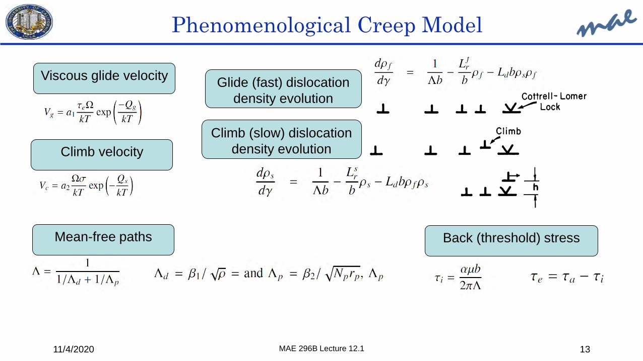
Phenomenological Creep Model
11/4/2020 MAE 296B Lecture 12.1 13
Viscous glide velocity
Climb velocity
Mean-free paths Back (threshold) stress
Glide (fast) dislocation density evolution
Climb (slow) dislocation density evolution

Phenomenological Creep Model
11/4/2020 MAE 296B Lecture 12.1 14
elastic Viscous glide Lattice diffusion
Climb-controlled glide

Phenomenological Creep Model
11/4/2020 MAE 296B Lecture 12.1 15

oxidationcorrosion
𝛾𝛾’ solvus
creepstrength
𝛾𝛾’ formingelements
GB carbides
Haynes 282: empirical design principles• Haynes 282 is a gamma-prime (𝛾𝛾’) precipitation-strengthened Ni-based superalloy for high-T applications.• Designed as a wrought alloy with balanced fabricability and mechanical properties.
16
𝛾𝛾’ content
Sims et al. 1987
better formability/weldability better mechanical properties
L. Pike, Superalloys, 2008.

Haynes 282: from processing to microstructure
17
T [℃]
1010℃, 2h
788℃, 8h
WQ
solution annealing+
components fabrication
solutionannealing
two-step aging
1121–1149℃
1000𝛾𝛾’ solvus
1032M23C6 solvus
1377Haynes 282 liquidus
L. Pike, Superalloys, 2008.J. Caron, Proceedings of the 8th International Symposium on Superalloy 718 and Derivatives, 2014.Kruger, K. L. Woodhead Publishing, 2017.
(Ti-Mo)-richMC carbides
Cr-rich M23C6“blocky” carbides
at GBs
ASTM 3-9 (144-18 𝜇𝜇𝜇𝜇)grain size
𝛾𝛾’ precipitates in the 𝛾𝛾 matrix (spherical D~20nm, ~20% v.f, unimodal)
t [h]

Creep lifetime estimation• Creep lifetime estimation is typically performed
with stress-LMP curves.
• Lifetime varies significantly depending on:1. sample dimensions (sheet vs plate)2. microstructure (grain size and
precipitates)
• Lifetime prediction is inaccurate for1. Non-standard materials processing2. Rafting microstructures3. Heat-affected zones (HAZ)
• Conservative design has significant impact on costs.
28x lifetime
72h 2016h
K. Vattappara, 2019.

Physics-based creep modeling• Assuming Class II solid solution alloy behavior:
1. Nabarro-Herring creep (self diffusion of vacancies)2. Dislocation creep (glide + diffusion-assisted climb)3. Q = Ni self-diffusion coefficient
• Creep rate:𝑘𝑘𝑘𝑘𝐷𝐷𝐿𝐿𝐺𝐺𝐺𝐺
𝜖𝜖 = 𝐴𝐴𝑁𝑁𝑁𝑁𝐺𝐺𝑑𝑑
2 𝜎𝜎𝐺𝐺 +𝐴𝐴𝑐𝑐
𝜎𝜎𝐺𝐺
5
𝐷𝐷𝐿𝐿 = 𝐷𝐷0𝑒𝑒𝑒𝑒𝑒𝑒 −𝑄𝑄𝑅𝑅𝑘𝑘
• Steady-state creep data is collected from the literature as a function of stress, temperature, and grain size.
• We want to explain this data based on simple physics-based models.

Physics-based creep modeling• 𝛾𝛾′ precipitates cause a “threshold” stress:
𝑘𝑘𝑘𝑘𝐷𝐷𝐿𝐿𝐺𝐺𝐺𝐺
𝜖𝜖 = 𝐴𝐴𝑁𝑁𝑁𝑁𝐺𝐺𝑑𝑑
2 𝜎𝜎𝐺𝐺
+ 𝐴𝐴𝑔𝑔𝜎𝜎𝐺𝐺
3+ 𝐴𝐴𝑐𝑐
𝜎𝜎 − 𝜎𝜎𝑡𝑡𝑡𝐺𝐺
5
• The threshold stress is determined from micromechanical simulations, assuming that its major contribution is due to the dislocation-precipitates bypass stress.
• 𝜎𝜎𝑡𝑡𝑡 was estimated to be approximately 70MPa for Haynes 282.
• Haynes 282 has high Mo content. Mo causes large lattice misfit.• Assuming Class I solid solution alloy behavior:
1. Nabarro-Herring creep (self diffusion of vacancies)2. Dislocation creep (viscous glide + diffusion-assisted
climb)3. Q = Mo self-diffusion coefficient
• Creep rate:𝑘𝑘𝑘𝑘𝐷𝐷𝐿𝐿𝐺𝐺𝐺𝐺
𝜖𝜖 = 𝐴𝐴𝑁𝑁𝑁𝑁𝐺𝐺𝑑𝑑
2 𝜎𝜎𝐺𝐺 + 𝐴𝐴𝑔𝑔
𝜎𝜎𝐺𝐺
3+ 𝐴𝐴𝑐𝑐
𝜎𝜎𝐺𝐺
5

Micromechanical modeling of the threshold stress
𝛾𝛾′ − GSFE
𝛾𝛾 − GSFE
• Discrete Dislocation Dynamics (DDD) simulations were used to estimate the threshold stress for dislocations-precipitates bypass as a function of
1. Precipitates size2. Precipitates volume fraction3. 𝛾𝛾/𝛾𝛾’ lattice misfit
• Three possible bypass mechanisms
Haynes 282
AB
C

Lattice misfit and Mo effects
Haynes 282 ~15% stronger
L. Pike, Superalloys, 2008.
E. Artz et al., Progress in Mat. Sci. 2001.
M. Santella, 24th Annual Conference on Fossil Energy Materials, 2010
• Misfit stresses pin dislocations and increase the threshold stress.
Possible misfit effects:• Misfit ~0 reduces the 𝛾𝛾/𝛾𝛾’
surface energy and reduces precipitates coarsening kinetics
• Affects self-diffusion• Alters stress in matrix and
precipitates • Affects dislocations-
precipitates interaction

Linear elastic analysis coupled with strength-based limits give conservative MTBF because it is based on minimum properties and non-specific datasets.Non-linear elasto-viscoplastic analysis coupled with strain damage fraction rules is less
conservative and more relevant to operational transients. Conservatism must still be built in if exact microstructure information is not included.A microstructure-based creep model has been implemented to predict transient and
cyclic creep.Main creep mechanisms: viscous glide, climb, and diffusion. Slowest rate is due to
molybdenum. Some uncertainties exist regarding the effects of grain size and sample thickness. The model will be refined to address those with additional experiemnts.γ’ misfit stresses and dislocation-precipitate interaction have been implemented in our
Dislocation Dynamics Code (MODELIB) to predict fatigue and creep.
Conclusions