The GDT-based fusion neutron source as a driver of sub ...inened/documents/Ivanov.pdf · The...
32
The GDT-based fusion neutron source as a driver of sub- critical nuclear fuel systems Presented by A.A.Ivanov Budker Institute Novosibirsk, FZD Rossendorf, Joint Institute for Nuclear Research, Dubna, VNIITF, Snejinsk
Transcript of The GDT-based fusion neutron source as a driver of sub ...inened/documents/Ivanov.pdf · The...

The GDT-based fusion neutron source as a driver of sub-critical nuclear fuel systems
Presented by A.A.IvanovBudker Institute Novosibirsk, FZD Rossendorf, Joint
Institute for Nuclear Research, Dubna, VNIITF, Snejinsk

Budker INPNovosibirsk
Joint Institute for NuclearResearchDubna
Layout of the talk
Physics of GDT–based neutron sourceApplication as a driver for sub-critical fission reactorApplication as a MA burner Possible re-optimization GDT-NS for application as a driverConclusions

Budker INPNovosibirsk
Joint Institute for NuclearResearchDubna
3
Gas Dynamic Trap

Budker INPNovosibirsk
Joint Institute for NuclearResearchDubna
Basic principles of GDT operationThe Gas-Dynamic Trap is a version of a standard simple mirror whose characteristic features are – a very high mirror ratio, R , in the range of a few tens;– a relatively large length, L ,exceeding an effective mean free path, λiilnR /R, with respect to scattering into the loss cone.The warm target plasma is almost Maxwellian– behaves like an ideal gas in a container with a pinhole leakMHD-stable even though system is fully axially symmetric– non-negligible amount of plasma in the regions beyond the mirror throats, where magnetic field has favorable curvature– MHD ballooning/interchange modes limit stability at β 40-60%The electron neat flux to the end walls is suppressed by strong reduction of magnetic field in expanders
4

Budker INPNovosibirsk
Joint Institute for NuclearResearchDubna
Requirements to VNS for fusion materials testing
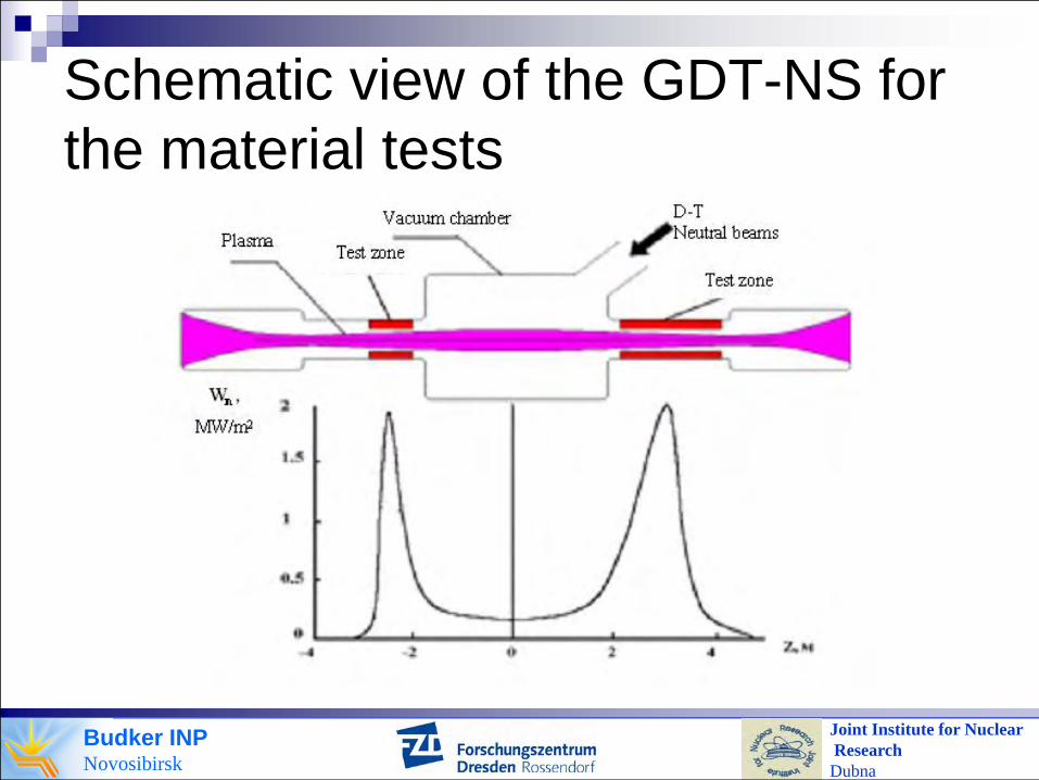
Fusion neutron spectrumAbout 2MW/m2 neutron flux or higher for accelerated testsSmall enough gradient of neutron flux densityContinuous operationAvailability more than 70%Reasonable tritium consumption
Budker INPNovosibirsk
Joint Institute for NuclearResearchDubna
Schematic view of the GDT-NS for the material tests

Budker INPNovosibirsk
Joint Institute for NuclearResearchDubna
Basic set of parameters for two and three component version of GDT-NS
Parameter Two component version Three component versionTritium beam energy (keV) 240 94
Deuterium beam energy (keV) - 80
Tritium beam power (MW) 20 6.5
Deuterium beam power (MW) - 8.5
Electron temperature (keV) 0.6 1.1
Plasma density (m-3) 2 x10²⁰ 2 x10²⁰
Plasma radius at the center (m) 0.06 0.08
Mirror ratio 20 15
Central field (T) 1.25 1.8
Injection angle (deg.) 20 40
Max. neutron flux (MW/m2) 3.9 1.8 – 2.0
Power consumption (MW) 50 60
Budker INPNovosibirsk
Joint Institute for NuclearResearchDubna
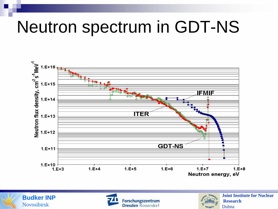
Neutron spectrum in GDT-NS

Budker INPNovosibirsk
Joint Institute for NuclearResearchDubna
GDT-NS: reference set of parametersPOWER CONSUMPTION - 47 MW
MAGNETIC FIELD IN MIRRORS, Bm = 13 T; MIRROR RATIO R =10
INJECTION ANGLE, θ = 300
INJECTION ENERGY - 65 keV
PLASMA DIAMETER AT MIDPLANE, 2a = 16 cm
RATIO OF ELECTRON TEMPERATURE TO THEINJECTION ENERGY Te / EINJ = 10 -2
MIRROR-TO-MIRROR, 11.4 mNEUTRON SOURCE INTENSITY – 7 1017 s-1

Budker INPNovosibirsk
Joint Institute for NuclearResearchDubna
Neutron flux density vs injection energy

Budker INPNovosibirsk
Joint Institute for NuclearResearchDubna
Neutron flux density vs electron temperature
Injection energy 65keVPower consumption 60MW

Budker INPNovosibirsk
Joint Institute for NuclearResearchDubna
Cutaway view of the GDT-NS

Budker INPNovosibirsk
Joint Institute for NuclearResearchDubna
Elevation view of GDT-NS

Budker INPNovosibirsk
Joint Institute for NuclearResearchDubna
Neutron yield profile in GDT-NS

Budker INPNovosibirsk
Joint Institute for NuclearResearchDubna
Neutron field characteristics

Budker INPNovosibirsk
Joint Institute for NuclearResearchDubna
16
GDT device – general view

Budker INPNovosibirsk
Joint Institute for NuclearResearchDubna
Physics issues addressed in the experiments
Factors controlling electron temperatureMicrostability of fast ions Steady state operation Ballooning instability thresholdEffect of ambipolar fields on confinementEffect of plasma rotation/vortex barrier formationNon-paraxial effects due to high β
Budker INPNovosibirsk
Joint Institute for NuclearResearchDubna
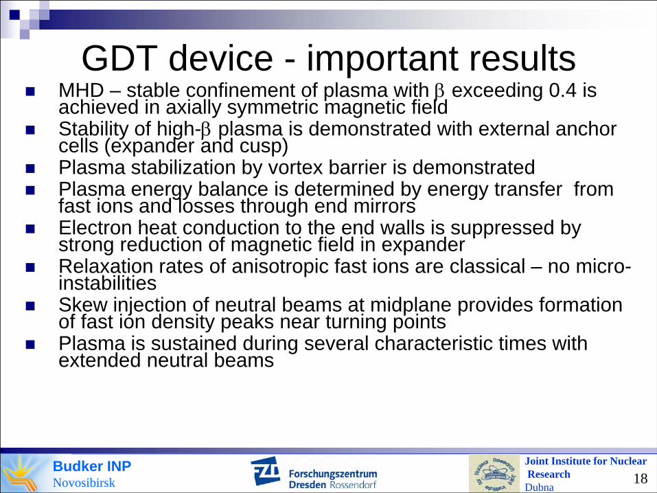
GDT device - important resultsMHD – stable confinement of plasma with β exceeding 0.4 is achieved in axially symmetric magnetic fieldStability of high-β plasma is demonstrated with external anchor cells (expander and cusp)Plasma stabilization by vortex barrier is demonstratedPlasma energy balance is determined by energy transfer from fast ions and losses through end mirrorsElectron heat conduction to the end walls is suppressed by strong reduction of magnetic field in expanderRelaxation rates of anisotropic fast ions are classical – no micro-instabilitiesSkew injection of neutral beams at midplane provides formation of fast ion density peaks near turning pointsPlasma is sustained during several characteristic times with extended neutral beams
18
Budker INPNovosibirsk
Joint Institute for NuclearResearchDubna
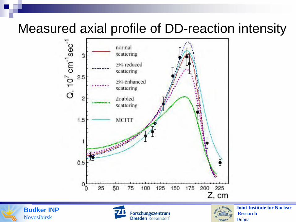
Measured axial profile of DD-reaction intensity

Budker INPNovosibirsk
Joint Institute for NuclearResearchDubna
20
NB energy 65keV
Neutron flux vs plasma temperature
65keV injection energy

Budker INPNovosibirsk
Joint Institute for NuclearResearchDubna
21
Electron temperature vs time

Budker INPNovosibirsk
Joint Institute for NuclearResearchDubna
βmax ≈ 40%
nf ≈ 5x10¹⁹ m-3
22
Plasma β in steady stay with D0
beams

Budker INPNovosibirsk
Joint Institute for NuclearResearchDubna
Formation of vortex barrier

Budker INPNovosibirsk
Joint Institute for NuclearResearchDubna
End loss reduction by fast ion density peaking near the ends
Peak density in local mirror cell vs trapped NBpower
Reduction of end loss current density with beam injection into local mirror cell

Budker INPNovosibirsk
Joint Institute for NuclearResearchDubna
TeMean
ionenergy
Confinementtime
Injectedpower
Electron density
Experiment with max Te 230eV 8.0keV Transient
regime 3.5MW 1.5x10¹⁹m-3
Standard experimental scenario
160eV 10keV 0.001s 3.5-4.0MW 5.0x10¹⁹m-3
Fusion triple product (nτEi=2.0x10¹⁷keVm-3s)
Maximum stored energy 1.2 KJ
Maximum β <beta>≈50% at B=0.5TMaximum density >1020m-3
Values in bold are maximum attained ones.
25
Plasma parameters in GDT
Budker INPNovosibirsk
Joint Institute for NuclearResearchDubna
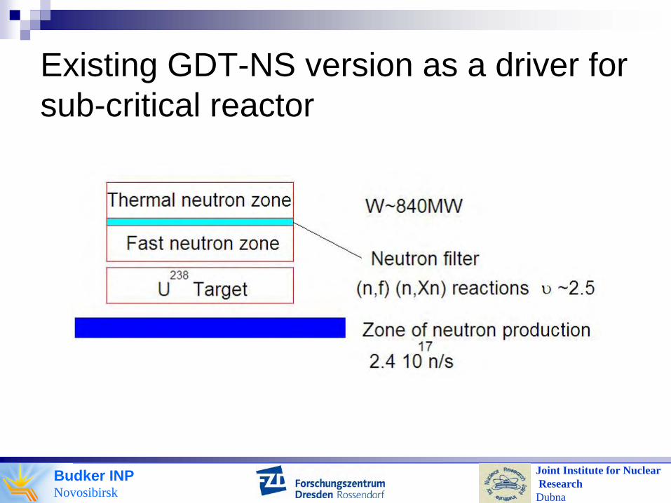
Existing GDT-NS version as a driver for sub-critical reactor

Budker INPNovosibirsk
Joint Institute for NuclearResearchDubna
Results of simulations
Neutron production in driver 2.4 1017 s-1
Overall multiplication factor ≤ 0.95Thermal power generated ~0.5GWNeutron shield for SS coils Pb+water
60cmFilter material Pb 10cm
Budker INPNovosibirsk
Joint Institute for NuclearResearchDubna
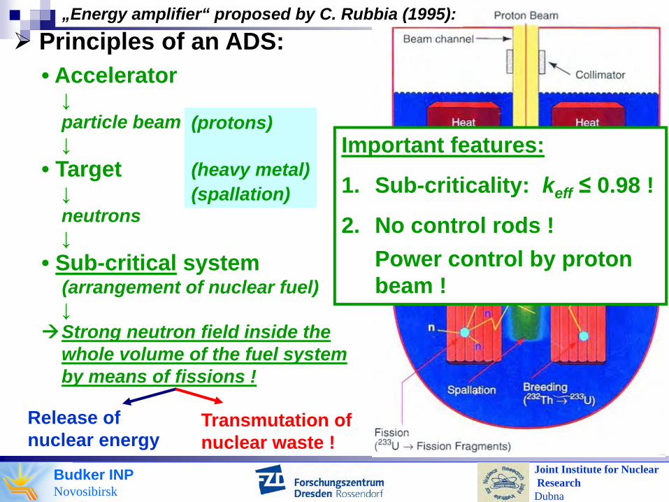
„Energy amplifier“ proposed by C. Rubbia (1995):
• Accelerator↓particle beam↓
• Target↓neutrons↓
• Sub-critical system(arrangement of nuclear fuel)↓Strong neutron field inside thewhole volume of the fuel systemby means of fissions !
Release ofnuclear energy
Transmutation of nuclear waste !
(protons)
(heavy metal)(spallation)
Principles of an ADS:
Important features:
1. Sub-criticality: keff ≤ 0.98 !
2. No control rods !Power control by proton beam !

Budker INPNovosibirsk
Joint Institute for NuclearResearchDubna
Reflector
Core
● Driven sub-critical system, ADS, FDS ?z
r
Effective multiplication factor: keff
Sub-critical system: keff < 1 = 0Reactor: keff = 1 =const. > 0Driven system: keff < 1 ~ S
n
Accelerator
Introduction – Nuclear systems
pEp ≈ 1 GeVIp= 10 … 200 mA
Spallationn´s/p=10-30
Driven systems:keff determines the self-multiplicity of the system:
keff < 1: 0.95 ... 0.97
Meff=keff/(1-keff): 20 ... 30feff=Meff/ν : 6 ... 10
Budker INPNovosibirsk
Joint Institute for NuclearResearchDubna
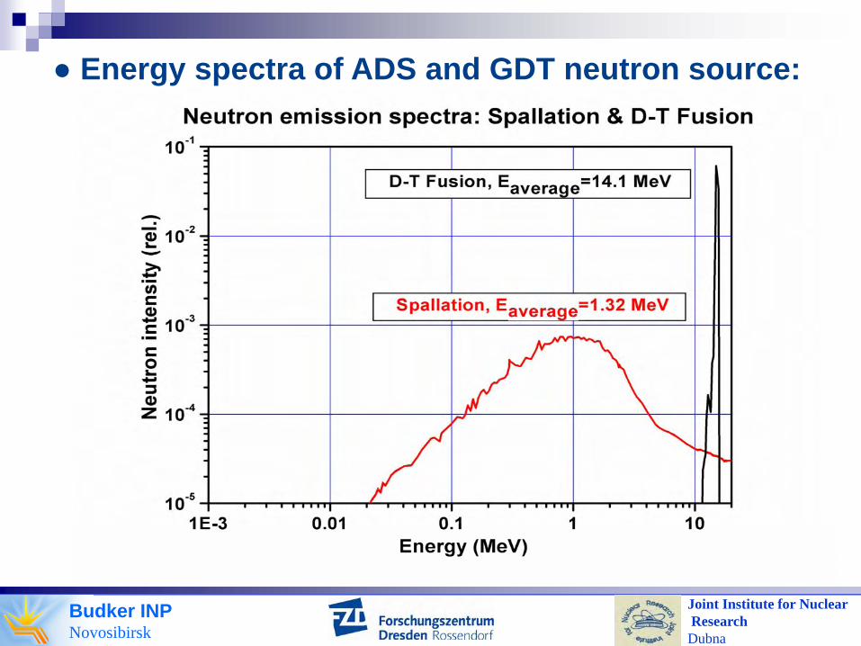
● Energy spectra of ADS and GDT neutron source:

Budker INPNovosibirsk
Joint Institute for NuclearResearchDubna
total
n,2n
n,3nn,γ
10 MeV

Budker INPNovosibirsk
Joint Institute for NuclearResearchDubna
Consideration of GDT-NS for fission fuel systems
Re-arrangement of neutron production zone (elongation (keff<0.97) to L ≈ 5 m on each side gives: Sn=2.5·1018 n/s, Pfus=7.1 MW, Pfis ≈ 1400 MW, Pinp ≈ 200 MW)Re-optimization of operational parametersIncrease of electron temperature (Te higher than 1.5keV would provide higher efficiency than ADS)Reduction of axial losses by ambipolar potential peaks (demonstrated)On-site tritium breeding
K. Noack,et al, Annals of Nuclear Energy,35(7), pp.1216-1222, (2008)
P.Bagryansky, et al, Fusion eng. and design,70, pp. 13-33, (2004)