Fusion neutron research in Novosibirsk including experiments

ORNL/TM-2019/1453
U.S. Fusion D-Li Neutron Irradiation Facility: Fusion Prototypic Neutron Source (FPNS) Technology Study
Egle, B. Ferguson, P. White, J. December 2019

DOCUMENT AVAILABILITY Reports produced after January 1, 1996, are generally available free via US Department of Energy (DOE) SciTech Connect. Website www.osti.gov Reports produced before January 1, 1996, may be purchased by members of the public from the following source: National Technical Information Service 5285 Port Royal Road Springfield, VA 22161 Telephone 703-605-6000 (1-800-553-6847) TDD 703-487-4639 Fax 703-605-6900 E-mail [email protected] Website http://classic.ntis.gov/ Reports are available to DOE employees, DOE contractors, Energy Technology Data Exchange representatives, and International Nuclear Information System representatives from the following source: Office of Scientific and Technical Information PO Box 62 Oak Ridge, TN 37831 Telephone 865-576-8401 Fax 865-576-5728 E-mail [email protected] Website http://www.osti.gov/contact.html
This report was prepared as an account of work sponsored by an agency of the United States Government. Neither the United States Government nor any agency thereof, nor any of their employees, makes any warranty, express or implied, or assumes any legal liability or responsibility for the accuracy, completeness, or usefulness of any information, apparatus, product, or process disclosed, or represents that its use would not infringe privately owned rights. Reference herein to any specific commercial product, process, or service by trade name, trademark, manufacturer, or otherwise, does not necessarily constitute or imply its endorsement, recommendation, or favoring by the United States Government or any agency thereof. The views and opinions of authors expressed herein do not necessarily state or reflect those of the United States Government or any agency thereof.

ORNL/TM-2019/1453
Fusion Energy Division
U.S. FUSION D-LI NEUTRON IRRADIATION FACILITY: FUSION PROTOTYPIC NEUTRON SOURCE (FPNS) TECHNOLOGY STUDY
Egle, Brian Ferguson, Phillip
White, James
December 2019
Prepared by OAK RIDGE NATIONAL LABORATORY
Oak Ridge, TN 37831-6283 managed by
UT-BATTELLE, LLC for the
US DEPARTMENT OF ENERGY under contract DE-AC05-00OR22725


iii
CONTENTS
CONTENTS ................................................................................................................................................. iii ACRONYMS ................................................................................................................................................ v ACKNOWLEDGMENTS .......................................................................................................................... vii EXECUTIVE SUMMARY ......................................................................................................................... ix 1. INTRODUCTION ................................................................................................................................ 1 2. MEETING DESIGN REQUIREMENTS ............................................................................................. 1 3. COST ESTIMATE ............................................................................................................................... 2
3.1 ION SOURCE ............................................................................................................................. 2 3.2 ACCELERATOR SYSTEM ....................................................................................................... 3 3.3 TARGET SYSTEM .................................................................................................................... 4 3.4 CONVENTIONAL FACILITIES ............................................................................................... 4 3.5 CONTINGENCY AND COST RANGE .................................................................................... 5
4. SCHEDULE DISCUSSION ................................................................................................................. 5 5. SUMMARY .......................................................................................................................................... 6 REFERENCES ............................................................................................................................................. 7 APPENDIX A. ION SOURCE COST AND TRL ESTIMATE ............................................................... A-1 APPENDIX B. ACCELERATOR SYSTEMS COST REPORT .............................................................. B-1


v
ACRONYMS
AACE Association for the Advancement of Cost Estimating appm atomic parts per million CW continuous wave dpa displacements per atom D-L deuterium-lithium DOE Department of Energy D-T deuterium-tritium DTL drift tube linac (DTL) FES Office of Fusion Energy Sciences FPNS Fusion Prototypic Neutron Source IFMIF International Fusion Materials Irradiation Facility IFMIF-DONES IFMIF-DEMO Oriented Neutron Source IFMIF EVEDA IFMIF engineering validation and engineering design activities LANL Los Alamos National Laboratory LEBT Low Energy Beam Transport LEDA Low Energy Demonstration Accelerator linac linear accelerator MEBT Medium-Energy Beam Transport NC normal conducting ORNL Oak Ridge National Laboratory RFQ radiofrequency quadrupole SCRF HWR superconducting RF half-wave resonator SNS Spallation Neutron Source VLT Virtual Laboratory for Technology


vii
ACKNOWLEDGMENTS
This work was carried out with support from the US Department of Energy Office of Fusion Energy Sciences.
The authors of this report wish to acknowledge the contributions of Rob Welton (Oak Ridge National Laboratory) and Luigi Celona (the Italian National Institute for Nuclear Physics), and of Robert Garnett (Los Alamos National Laboratory), respectively, to the documents included as Appendix A, ”Ion Source Cost and TRL Estimate,” and Appendix B, “Accelerator Systems Cost Report.”


ix
EXECUTIVE SUMMARY
A primary engineering challenge for the realization of fusion energy involves the development of high-performance structural and plasma-facing materials with dimensional stability and resistance to neutron degradation of mechanical properties. The harsh fusion environment, including high levels of helium production and other transmutation products along with high operating temperatures, poses an extreme challenge for materials. Identifying materials that can withstand these conditions is a high priority for fusion energy research. Critical to resolving this gap in scientific understanding is developing a neutron source facility with the ability to mimic the extreme conditions in a fusion reactor.
Working with the Department of Energy (DOE) Office of Fusion Energy Sciences (FES), Oak Ridge National Laboratory (ORNL) and the Virtual Laboratory for Technology (VLT) organized a workshop to discuss the need for a Fusion Prototypic Neutron Source (FPNS). [1] While there are a variety of uses for FPNS neutrons, the main driver of US interest is expanding the scientific understanding of materials degradation in the deuterium-tritium (D-T) fusion environment. FPNS will help build the scientific foundation required to enable design of a next step fusion device. Using specifications from previous projects as a guide, key parameters were agreed upon for a near term, moderate cost US facility that would be complementary to the more extensive plans of the International Fusion Materials Irradiation Facility (IFMIF). Types of facilities that could potentially meet those criteria were identified. A scoping study for three technologies was initiated to answer three critical questions: 1) Can the concept meet the key parameters, 2) What is the estimated cost, and 3) What is the estimated schedule. One approach selected for the scoping study is a D-Li stripping source similar to the design of the IFMIF but at a lower beam power and atomic displacement rate for cost and schedule reasons. The purpose of this report is to document the results of the D-Li stripping source option study, providing answers to the three questions.
The approach to generating a fusion prototypic neutron source using a deuteron beam incident on a flowing lithium target has been studied for more than 40 years. As a result of the research and development recently executed primarily in Europe and Japan, the ability of this approach to meet key parameters (damage parameters, irradiation volume) outlined in the US workshop for a near-term, moderate cost fusion prototypic neutron source facility is not in doubt. The main question that must be answered is the cost of such a facility. As a result, a strong focus was placed on understanding alternatives for developing the facility and their relative costs. The project was broken into four components for the cost estimate: the ion source, accelerator, lithium target system, and conventional facilities.
The cost of the accelerator is an important cost driver for the D-Li stripping concept. To fully understand the range of the accelerator cost, multiple alternatives were considered including normal conducting and superconducting linacs and the frequency of the radiofrequency quadrupole. Multiple previous design studies dating from 1989 through 2017 were examined (costs were escalated to 2019 dollars) and compared. After analysis, two options were selected for costing, one superconducting and one room temperature. We found similar project costs for the two accelerator options, on the order of $100M including design and project management but excluding contingency. Including everything except the conventional facilities, the estimate for the neutron source facility is estimated to be $220M without contingency.
Additional significant costs for the facility are the conventional costs arising from the need to construct buildings for the accelerator and target facilities, bringing electrical power to the site including a new substation, and removing the heat from the facility using heat exchangers. While ORNL would oversee this work, much of the effort would be executed by contractors. Estimates for this effort was based on similar projects that are currently being executed at ORNL or were executed at ORNL in the recent past. The estimate for conventional facilities for the neutron facility is $173M without contingency, bringing the total project cost to $393M without contingency. With a 50% contingency, the estimated cost is $589M.

x
The estimate range was established using guidance from the Association for the Advancement of Cost Engineering (AACE). Specifically, guidance from recommended practice 17R-97 provides insight on the expected accuracy range of estimates based on the degree of project definition and the position of the project in the stage-gate process or maturity timeline. An AACE Class 5 type estimate is appropriate for concept screening. The expected accuracy range includes a low end of -50% to -20% and a high end of +30% to +100% around the estimated cost. For the D-Li stripping neutron source, a -20% to +100% cost range was applied for a recommended cost range of $471M to $1,179M.
Less emphasis was placed on determining the project schedule due to the fact that the project costs were large and may eliminate this option from consideration. The development of the accelerator facility may require on the order of five years without contingency. A more realistic schedule with contingency may be seven years. However, this estimate should be scrutinized in a preconceptual design activity if a more realistic estimate is needed.
Finally, one lesson learned in this process is that the requirements for a near-term, moderate cost facility drives the alternative selection toward existing facilities and infrastructure. The D-Li stripping neutron source option requires a green field site due to the lack of existing buildings and infrastructure that can be reused for this effort. As a result, the conventional facilities costs are a significant fraction of the total facility cost. Other neutron source options where buildings, electrical power, and cooling infrastructure already exist may be able to meet the requirements for a near term, moderate cost facility.

1
1. INTRODUCTION
A neutron source capable of mimicking the extreme environment of a fusion energy device, including the atomic displacements, transmutation product generation, and high-operating temperatures, will play a critical role in the realization of fusion energy. While much progress has been made in the basic understanding of radiation damage in materials, there are still fundamental knowledge gaps in the understanding of materials in a fusion energy device. These gaps must be addressed to enable the design and construction of a reliable fusion energy device. Current fusion experiments are not capable of fulfilling this need as they run in a pulsed mode and do not accumulate significant radiation damage. For example, in ITER, the large international fusion experiment under construction in France, structural damage in the reactor steels will be on the order of 2 displacements per atom (dpa) at the end of its operational life; damage creation in a proposed fusion power plant is expected to be on the order of 20 dpa per year of operation, or approximately an order of magnitude higher than the lifetime damage accumulated at ITER [2].
Working with the Department of Energy (DOE) Office of Fusion Energy Sciences (FES), Oak Ridge National Laboratory (ORNL) and the Virtual Laboratory for Technology (VLT) organized a workshop to discuss the need for a Fusion Prototypic Neutron Source (FPNS), which could be constructed in the near term at moderate cost. [1] The intent would be for fusion neutrons to be available as soon as possible to initiate scientific studies on fusion materials, complementing the more ambitious projects planned in Europe [3] and Japan [4]. A FPNS will help build the scientific foundation required to enable design of a next step fusion device. Specifications were developed for a near term, moderate cost facility and facilities that could potentially meet those criteria were identified. A scoping study for three technologies was initiated: 1) a D-Li stripping source similar to the design of the International Fusion Materials Irradiation Facility (IFMIF) but at a lower beam power and atomic displacement rate, 2) a neutron generator concept proposed by Phoenix, and 3) a spallation target system approach proposed by Los Alamos National Laboratory (LANL). The purpose of this report is to document the results of the D-Li stripping source option including an analysis on meeting the performance criteria, an estimated cost range, and an estimate on the length of time required to develop the facility.
2. MEETING DESIGN REQUIREMENTS
The primary mission of FPNS is to establish the materials science knowledge base to understand materials degradation in a D-T fusion environment. That base will support design for a next step device which will require fusion-relevant neutron irradiation studies on the structural and functional materials to at least tens of dpa for design considerations. FPNS will also help provide the scientific foundation to design and build more advanced fusion neutron facilities under consideration internationally. To achieve these goals, a set of key parameters was agreed upon at the FPNS workshop [1] and is shown in Table 1. These parameters are based upon prior discussions for IFMIF and other facilities, with the damage rate reduced to reduce the overall facility cost while still meeting the goal of providing information to support the design of the next step fusion facility. The sample volume is also reduced based on research using miniature sized materials testing samples and what may be achievable in taking advantage of the irradiation volume. Reducing the sample volume is also focused on reducing overall facility costs.

2
Table 1. Key parameters for a US FPNS
Parameter Guideline Damage rate ~8-11 dpa/calendar year (Fe) Spectrum ~10 appm He/dpa (Fe) Sample volume in high flux zone ≥ 50 cm3 Temperature range ~300-1000°C Temperature control 3 independently monitored and controlled regions Flux gradient ≤ 20%/cm in the plane of the sample
Robert Serber theoretically demonstrated the possibility of producing high-energy neutrons by a process in which accelerated deuterons are stripped of their protons when hitting a target while the neutrons continue in the forward direction [5]. This process has been the basis for neutron facility designs for more than forty years. In the 1970s, the first designs for high energy neutron sources using this stripping reaction were developed in the US [6,7]. In the 1980s, rapid advances in high-current linear accelerators led to the design studies of several accelerator-driven neutron sources for satisfying the requirements of a high-flux, high-volume fusion materials testing facility [8,9]. Calculations of the neutron source performance within reasonable error bars were verified in an experiment as part of the IFMIF validation activities and documented in a Forschungszentrum Karlsruhe report [10].
The IFMIF project has been refined to focus more closely on a proposed fusion demonstration power station, or DEMO [11], instead of a fusion power plant. As a result, the IFMIF-DEMO Oriented Neutron Source (IFMIF-DONES) has been developed with lower annual damage rate than the original IFMIF project and a somewhat reduced irradiation volume. The goal for IFMIF-DONES is greater than 10 dpa per year in iron with an irradiation volume of 300 cubic centimeters [12]. Comparing to Table 1, these parameters are very close to those identified for a US FPNS. Multiple papers over the years demonstrate the ability of IFMIF and IFMIF-DONES to meet or exceed the key parameters indicated in Table 1 [3, 13, 14, 15]. By selecting accelerator parameters similar to IFMIF-DONES, e.g., deuteron energy of 40 MeV and continuous-wave (CW) beam current of 125 mA, the design for the FPNS should meet or exceed the parameters identified in Table 1.
3. COST ESTIMATE
To compare neutron source options for a FPNS, it is necessary to develop a cost estimate. However, it is important to keep in mind that at this time the estimate is an AACE Class 5 estimate. No conceptual design was completed to support the estimate. The estimate relies on experience from past and existing projects. As a Class 5 estimate, the accuracy range is expected to be from -50% to -20% on the low end and from +30% to +100% on the high end depending on the technological complexity of the project. For a project as complex as a D-Li stripping neutron source, the cost range will be determined as -20% to +100% of the derived point estimate including contingency. The low end of the range is typically not where estimates fail and, as a result, the -20% lower end was deemed acceptable for this cost range. Costs for each system will be discussed separately in the following sections.
3.1 ION SOURCE
Ion source design and construction was a significant part of the Spallation Neutron Source (SNS) project, and ion source development continues to be an important part of SNS operations. The ion source team at SNS continues to purchase components and build hardware for ion source research. For this reason, the ion source for the D-Li stripping option was estimated by the ion source team at SNS. The team considered high intensity ion sources in various stages of design, construction, operation, or decommissioning for eight international facilities. The recommendation for the ion source design relies heavily on the design of the European Spallation Source design, pulling heavily from other designs and experiences. The estimated cost

3
to deliver the system is approximately $7M, which is shown in Table 2. The $7M cost estimate excludes design and contingency which are included separately in the Table 2 roll up. Details of the design selection and cost estimate can be found in Appendix A.
Table 2. Cost estimate for the D-Li stripping FPNS
Cost Scaling Factors Point estimate [$M] Accelerator Systems 220 Ion Source Systems 7 Accelerator Systems 75 Li target and sample handling
systems 33
Project Management 12% of system cost 14 Design 25% of system cost 29 Instrumentation and Controls 15% of system cost 17 Commissioning 5% of system cost 6 As-built drawings 4% of system cost 5 Fees, overhead, etc. 30% of system cost 34
Conventional Facility 173 Facility buildings $1000 to 1300 per sqft 35000 sqft 42 Li building with steel liner $1075 to 1375 per sqft 6000 sqft 8 Site Preparations $1M per acre 4 acres 4 Utilities extensions $250/linear foot/utility 1500 ft x 3 utilities 1 Shop and Operator Building $600/sqft 10000 sqft 6 Central Utilities Building
50 MW thermal 30
Electrical Substation 50 MW electric 25 General Contractor Fee 15% of facility cost 17 Design 15% of facility cost 17 Contractor management and
integration 20% of facility cost 23
Project Subtotal 393 Project contingency 50% of total project 196 Total Project Cost 589
3.2 ACCELERATOR SYSTEM
Several past accelerator system design studies were reviewed and an analysis of alternatives was completed to assess the range of accelerator parameters and accelerating structure types that can potentially meet the requirements of a 125-mA, 40-MeV, D-Li Fusion Neutron Facility. The design studies reviewed included past LANL designs for IFMIF and designs based on the use of modified versions of the LANL Low Energy Demonstration Accelerator (LEDA). Also reviewed were the past IFMIF engineering validation and engineering design activities (EVEDA) design iterations that explored several options for the main linear accelerator (linac) including the use of an Alvarez drift tube linac (DTL), interdigital accelerating structures, and a superconducting RF half-wave resonator (SCRF HWR) based main linac. Results of the analysis of

4
alternatives were used to develop two options for consideration based on a common set of accelerator system parameters:
• Ion Source and Injector – 140 mA D+, DC/CW operation (pulsed capability for tuning), 100 eV, transverse output emittance <0.25 π-mm-mrad.
• Low-Energy Beam Transport (LEBT) – 2 solenoid, gas neutralization, electron trap • Radio frequency quadrupole (RFQ) – 100 keV to 5 MeV, 125 mA CW • Medium-Energy Beam Transport (MEBT) – 4-5quadrupoles, 2 multi-gap buncher cavities • Main Linac – 5 MeV to 40 MeV, 125 mA CW (superconducting or normal conducting) • High-Energy Beam Transport (includes beam expander optics) – quadrupole magnet focusing lattice
for beam transport, multipole magnets for beam expansion and 2D uniform distribution, final configuration TBD based on Li target geometry.
Option 1 reproduces the 40-MeV Linear IFMIF Prototype Accelerator (IFMIF-EVEDA-LIPAc) design based on an RFQ and a SCRF HWR-based main linac. Option 2 is an alternative 40-MeV design based on an RFQ followed by a normal-conducting (NC) DTL main linac. Both options are assumed to use a LEDA-scaled RFQ design and both options can meet the accelerator requirements for a 125-mA, 40-MeV, D-Li Fusion Neutron Facility. Option 1 is significantly more complex to fabricate and operate. Option 2 may offer several advantages including simpler operation, however it will be more costly to operate due to the additional electrical power required for a fully NC main linac.
Several of the design studies, in addition to other reference sources, established a basis of estimate to compare Option 1 and Option 2 costs. Cost scaling factors were developed and used to estimate the accelerator system costs for each option. The results indicate that the total costs for either option are very similar: $74M for Option 1 and $70M for Option 2. For this study, a value of $75M excluding contingency was used for the accelerator cost, and that value can be found in Table 2. Details of the accelerator system technical scoping, as well as development of the costs, can be found in Appendix B. In addition, cross checks with system costs from previous designs are included.
3.3 TARGET SYSTEM
The design, cost estimate, construction, commissioning, and modifications to remote handling systems at ORNL typically include input from, or are led by, the Remote Systems Group in the Fusion Energy Division. Members of the group were actively engaged in the design and construction of the SNS target handling cell as well as many other remote handling projects at ORNL. The members of the group performed a bottom-up estimate for the lithium target system based upon designs that have been published previously. [3, 4] The design includes three sets of master-slave manipulators, three shield windows, a bridge crane with a servo manipulator, a 30-ton bridge crane for handling large components, a beam dump with a vault-like facility, and resources to detail the facility and integrate it with the building.
The cost estimate for the target system (not including the target building) is $33M excluding contingency (Table 2). A detailed report for the target facility is being developed but is not available at this time.
3.4 CONVENTIONAL FACILITIES
Conventional facilities includes the site preparation; buildings that contain the accelerator and target system; electric power for the system and the need for a new electrical substation; heat exchangers to remove the waste heat from the accelerator and the target; fees for the general contractor who will execute this work; and a management activity for ORNL to ensure that the contractor is integrated into the project and performs the work as specified. Design costs are broken out separately for conventional facilities versus the accelerator system because the design is of a more known nature and is not a first of a kind system.

5
Estimates for the structures rely on experience from past projects, including the SNS accelerator and target buildings, SNS beamline buildings, central facility buildings including the helium liquefier building, and several additional facilities. The cost of each facility was escalated to 2019 dollars and divided by the square footage of the building. Consistently the costs of the heavily shielded accelerator building, exclusive of the architect and engineering firm fee and ORNL management costs, were on the order of $1000-$1300 per square foot. For the cost estimates in Table 2, $1200 per square foot was used for the accelerator structures and $1275 per square foot was used for the target building to account for additional challenges associated with handling significant quantities of lithium metal. Similar scaling estimates were made for the shop building, which is a standard construction at ORNL with a cost range of $500-$700 per square foot.
The need for a new electrical substation and a Central Utilities Building is driven by the fact that approximately 50 MW of electric power, and thus heat-rejection capacity, will be required for the facility. The requirement for 50 MW of grid electricity and water-cooling capacity is estimated from a 10% grid electrical to beam-power efficiency of similar scale accelerators. [16] While not a routine part of construction, electrical substations have been added to ORNL for multiple projects. The estimate for an electrical substation draws heavily from this experience. The Central Utilities Building estimate benefitted from the computing facility construction occurring at ORNL, where a new 40 MW heat exchangers system is being installed to support the exascale supercomputer. The estimates for these components use recent data from purchase and installation of those heat exchangers.
The total cost estimate for conventional facilities is $173M exclusive of contingency, which is a significant portion of the total cost estimate. From this analysis, it is clear that conventional facilities must be minimized for any FPNS project to be categorized as moderate cost.
3.5 CONTINGENCY AND COST RANGE
To arrive at a point estimate, the summed cost of $393M must include a reasonable contingency. At this point in the project, a 50% contingency has been added. It could be argued for a higher contingency based on the lack of a conceptual design. More important than the point estimate is the cost range. Using the AACE recommendations for a Class 5 estimate (-20% to +100%), the cost range for a D-Li stripping version of FPNS is $471M - $1,179M.
4. SCHEDULE DISCUSSION
Because the cost estimate was considered critical for the D-Li stripping option for a near-term, moderate cost FPNS, more time and effort were expended on the cost as opposed to the schedule. However, the time required to design and construct a D-Li stripping FPNS was considered. A rough estimate based on a career of designing and constructing accelerators, including the LEDA accelerator, indicates that it is possible to design and construct an accelerator such as the options specified in five years. Adding time for contingency and commissioning provides a reasonable estimate with contingency of seven years for the project. A more accurate estimate can be developed should it be needed.

6
5. SUMMARY
A D-Li stripping source concept was considered as an option for a near term, moderate cost US FPNS. Analyses were completed by experts in the areas of the ion source, accelerator system, target system, and conventional facilities. The ability of the D-Li approach to meet the performance requirements of the US FPNS is well documented by the international community. Experiences from previous design studies, completed projects, and ongoing projects were leveraged to provide a cost estimate for this approach to a US FPNS. The point cost estimate was determined to be $589M with 50% contingency. The cost range for the Class 5 estimate was determined to be $471M to $1179M. A significant portion of the cost was due to conventional facilities. For a near term, moderate cost project, it is highly advantageous if not a requirement for existing facilities, utilities, or technical components to be leveraged for the project. For a green field approach to a D-Li stripping neutron source, the costs are likely too high to be considered a moderate cost facility.
The construction and commissioning of a D-Li stripping facility may meet the requirement for a near term facility, with an estimate of construction and commissioning of seven years. A more detailed schedule estimate can be developed if needed.

7
REFERENCES
[1] Wiffen, F. W., Summary Report on the Fusion Prototypic Neutron Source Workshop, VLT-2019-01,
held August 20-22, 2019. [2] Gilbert, M.R., Dudarev, S.L., Zheng, S., Packer, L.W.; Sublet, J.-Ch., An integrated model for materials
in a fusion power plant: transmutation, gas production, and helium embrittlement under neutron irradiation, Nuclear Fusion, 52 (8): 083019. doi:10.1088/0029-5515/52/8/083019.
[3] Knaster, J., et al., Overview of the IFMIF/EVEDA Project, Nuclear Fusion 57 (10), 2017. [4] Makoto, M., et al., Key conception of the remote maintenance for the target assembly of Advanced
Fusion Neutron Source (A-FNS), Fusion Engineering and Design, 146 (B), 1515-1519 (2019). [5] Serber, Robert, The Production of High Energy Neutrons by Stripping, Physical Review, 72, 1008–
1016. doi:10.1103/PhysRev.72.1008. [6] Grand, P., Batchelor, K.; Blewett, J. P.; Goland, A., Gurinsky, D., Kukkonen, J., Jr, and Snead, C. L.,
An Intense Li(d,n) Neutron Radiation Test Facility for Controlled Thermonuclear Reactor Materials Testing, Nuclear Technology, 29 (3), 327–336. doi:10.13182/NT76-A31598.
[7] Grand, P., Goland, A. N. (1977), An intense neutron source based upon the deuteron-stripping reaction, Nuclear Instruments and Methods, 145 (1): 49–76. doi:10.1016/0029-554X(77)90557-2.
[8] Lawrence, G. P.; Bhatia, T. S.; Blind, B.; Guy, F. W., Krakowski, R. A., Neuschaefer, G. H., Schnurr, N. M.; Schriber, S. O.; Varsamis, G. L., High-performance deuterium-lithium neutron source for fusion materials and technology testing, Proceedings of the 1989 IEEE Particle Accelerator Conference, Accelerator Science and Technology. 1: 684–687. doi:10.1109/PAC.1989.73222.
[9] Lawrence, George P, Accelerator-driven neutron sources for fusion materials testing, Journal of Fusion Energy, 10 (4): 319–326. doi:10.1007/BF01052133.
[10] U. v. Möllendorff, F. Maekawa, H. Giese, H. Feuerstein, A nuclear simulation experiment for the International Fusion Materials Irradiation Facility (IFMIF), Forschungszentrum Karlsruhe, Report FZKA-6764 (2002)
[11] Ciattaglia, S., et al., The European DEMO Fusion Reactor: Design Status and Challenges from Balance of Plant Point of View, IEEE Industrial and Commercial Power Systems Europe, 1-6. doi:10.1109/EEEIC.2017.7977853.
[12] Ibarra, A., A neutron source for fusion: The DONES project, presented at CERN, April 29, 2019. [13] Krolas, W. and A. Ibarra, The IFMIF-DONES Project, Nuclear Physics News, 29 (3), 28-32.
doi: 10.1080/10619127.2019.1643167. [14] A. Ibarra, R. Heidinger, P. Barabaschi, F. Mota, A. Mosnier, P. Cara & F. S. Nitti (2014) A Stepped
Approach from IFMIF/EVEDA Toward IFMIF, Fusion Science and Technology, 66:1, 252-259. DOI: 10.13182/FST13-778
[15] R. Heidinger, A. Ibarra, P. Barabaschi, P. Cara, A. Mosnier, F. Mota, F.S. Nitti (2014) Technical analysis of an early fusion neutron source based on the enhancement of the IFMIF/EVEDA accelerator prototype, Fusion Engineering and Design, 89, 2136-2140. DOI: 10.1016/j.fusengdes.2014.03.085
[16] Yakovlev, V., The Energy Efficiency of High Intensity Proton Drivers Concepts, presentation at The 8th International Particle Accelerator Conference, May 19, 2017.


APPENDIX A. ION SOURCE COST AND TRL ESTIMATE


Preliminary cost and TRL estimate of the ion source and LEBT for the Fusion Prototypic Neutron Source
Robert Welton Nov 21, 2019

A-3
DOCUMENT AVAILABILITY Reports produced after January 1, 1996, are generally available free via US Department of Energy (DOE) SciTech Connect. Website www.osti.gov Reports produced before January 1, 1996, may be purchased by members of the public from the following source: National Technical Information Service 5285 Port Royal Road Springfield, VA 22161 Telephone 703-605-6000 (1-800-553-6847) TDD 703-487-4639 Fax 703-605-6900 E-mail [email protected] Website http://classic.ntis.gov/ Reports are available to DOE employees, DOE contractors, Energy Technology Data Exchange representatives, and International Nuclear Information System representatives from the following source: Office of Scientific and Technical Information PO Box 62 Oak Ridge, TN 37831 Telephone 865-576-8401 Fax 865-576-5728 E-mail [email protected] Website http://www.osti.gov/contact.html
This report was prepared as an account of work sponsored by an agency of the United States Government. Neither the United States Government nor any agency thereof, nor any of their employees, makes any warranty, express or implied, or assumes any legal liability or responsibility for the accuracy, completeness, or usefulness of any information, apparatus, product, or process disclosed, or represents that its use would not infringe privately owned rights. Reference herein to any specific commercial product, process, or service by trade name, trademark, manufacturer, or otherwise, does not necessarily constitute or imply its endorsement, recommendation, or favoring by the United States Government or any agency thereof. The views and opinions of authors expressed herein do not necessarily state or reflect those of the United States Government or any agency thereof.

A-4
Neutron Sciences Directorate Research Accelerator Division
Preliminary cost and TRL estimate of the ion source and LEBT for the Fusion Prototypic Neutron Source
Robert Welton Luigi Celona
Nov 21, 2019
Prepared by OAK RIDGE NATIONAL LABORATORY
Oak Ridge, TN 37831-6283 managed by
UT-BATTELLE, LLC for the
US DEPARTMENT OF ENERGY under contract DE-AC05-00OR22725

A-5
CONTENTS
1. Concept of the Fusion Prototypic Neutron Source (FPNS) and the requirements of the ion source / Low
Energy Beam Transport (LEBT)
2. Current state-of-the-art of high intensity H+ and D+ sources for accelerators
3. Cost estimate based on the European Spallation Source ion source / LEBT system
4. Estimated TRL for the ion source and LEBT
ABSTRACT
The development of a fusion prototypic neutron source (FPNS) to evaluate materials exposed to fusion reactor environments has been a long-standing goal of the fusion community. D-T fusion plasmas emit intense fluxes of ~14 MeV neutrons which create unique damage profiles within structural wall materials that cannot be studied using neutrons from fission reactors nor conventional spallation neutron sources. A dedicated FPNS could be used to simultaneously irradiate many candidate sample materials with the correct neutron energies having a flux intensity sufficiently high to allow material evaluations to occur much more rapidly than in actual fusion reactors. Towards this end, the US Department of Energy (DOE) Office of Fusion Energy Sciences (FES) has asked ORNL to conduct a preliminary study of a linac-driven, D-Li neutron source. This scheme would involve a D+ ion source coupled to an RFQ (Radio Frequency Quadrupole) accelerator through a LEBT (Low Energy Beam Transport). Beam from the RFQ would then inject a LINAC which would direct beam onto a flowing Li target producing the desired neutron flux. In this work, we provide preliminary estimates of the cost, schedule and TRL (Technical Readiness Level) of the ion source and LEBT subsystems of this project. The source should provide D+ CW/DC beams of ~140 mA at ~100 keV with an RMS normalized emittance ε < 0.25 π mm mrad. The cost estimate was based on the cost of the ion source and LEBT delivered to the ESS (European Spallation Neutron Source). It includes labor and materials needed for design integration, construction, installation and commissioning of the system while neglecting licensing costs of the design as well as the cost of implementing beam diagnostics and controls hard- and software. The cost was estimated to be ~$10M spanning ~ 4 years of effort employing ~3 FTEs. An ion source / LEBT TRL level of 5 was also determined by examination of the current state-of-the-art of accelerator-based high intensity/brightness H+ and D+ ion sources. Also note that if the beam current requirement of 125 mA at 100% duty factor was relaxed the TRL level will increase considerably.
1. CONCEPT OF THE D-Li FUSION NEUTRON FACILITY AND REQUIREMENTS
The development of a fusion prototypic neutron test facility to evaluate materials exposed to fusion reactor environments has been a long-standing goal of the fusion community [1]. While materials used in fission reactors has been studied and optimized for many decades, those needed for fusion devices have received comparatively little attention, despite their critical importance in enabling future fusion reactors like DEMO [2]. The energy spectrum of neutrons emitted from fission reactor is on the order of 2 MeV while that emitted from D-T fusion plasmas are ~14 MeV thereby inducing unprecedented levels of dislocation damage (100-200 dpa) to materials as well as significant transmuted He production [2]. This is especially the case when considering the necessarily large neutron fluxes emitted in commercial power generation. In order to produce neutrons in this energy range with intensities capable of simulating years of fusion reactor service, an accelerator-based approach is under consideration which utilizes the Li (d, xn) reaction as a source of neutrons [3]. CW beams of deuterons (~125 mA) can be accelerated to relevant energies by an RFQ and short ~ 40 MeV LINAC and then collided with Li in

A-6
a flowing loop 5 MW target producing sufficiently intense neutron beams. Although such facilities have been discussed and planned for years, the IFMIF (International Fusion Materials Irradiation Facility) project, a > $1B effort, is now being constructed and commissioned in Rokkasho, Japan [4]. Currently, the ion source, LEBT and RFQ are being commissioned but the overall project has been delayed due to resource limitations. Recently, the US Department of Energy (DOE) Office of Fusion Energy Sciences (FES) has asked ORNL to provide an estimated cost, timeframe and TRL (Technical Readiness Level) of constructing a scaled down version of IFMIF facility, presumably in the United States. This report provides a first glance, estimate of the cost, timeframe and TRL-level of the ion source and LEBT needed for the project. Should the DOE gain any further interest in constructing such a facility a much more in depth analysis should be undertaken. The desired ion source parameters have been defined for us from earlier workshops on the subject [3]. The proposed facility will require the ion source and LEBT parameters to be essentially the same as IFMIF: ~140 mA of D+ CW/DC extracted and transported through the LEBT at ~100 keV with an RMS normalized emittance ε < 0.25 π mm mrad). The beam from the RFQ that will be transported through the LINAC to target would be ~125 mA.
2. CURRENT STATE OF THE ART OF HIGH INTENSITY PROTON / DEUTERON SOURCES FOR HIGH ENERGY ACCELERATORS
Fortunately, a simple and robust 2.45 GHz microwave source was designed, built and tested at CRNL (Chalk River National Laboratory) in the early 1990’s. The CRNL team showed that by axially injecting ~1 kW of microwaves into a small plasma chamber which also contains an axial magnetic field, an over-dense plasma could be achieved. To accomplish this the magnetic field profile was adjusted such that the ECR condition (875G) was met close to the microwave injection point in the plasma chamber. The field profile then increased axially toward the central region of the plasma. This configuration was shown to be capable of producing ~90% proton fractions and cw current densities of ~120 mA/cm2 serving as the basis essentially all high intensity proton sources used over the next 30 years for high energy accelerator injection [5]. The source design was further developed at Los Alamos National Laboratory (LANL) and employed in the Low Energy Demonstration Accelerator (LEDA) where cw beams of ~100 mA have been accelerated to 6.7 MeV by their RFQ [6]. Since then several other projects have employed similar proton sources and LEBTs primarily supplied by either CEA (Commissariat à l’Energie Atomique, CEA/ Saclay) [7] or INFN (Istituto Nazionale di Fisica Nucleare – Laboratori Nazionali del Sud, Catania, Italy) [8]. Table I shows some of these facilities, either planned, under construction, operating or canceled. A small technology company, Pantechnik, even offers a permanent magnet version of the CEA source [9]. As mentioned above, the closest match to the requirements of the proposed FPNS would be the IFMIF ion source and LEBT which was designed, built and tested in Saclay by CEA based on their SILHI source [10]. This source and LEBT combined with an RFQ (designed by INFN) is currently part of the LIPAc accelerator which will eventually serve as one of the two accelerators for the IFMIF project. LIPAc is currently undergoing commissioning in Rokkasho, Japan, the chosen site of the IFMIF project [4]. To date, pulsed D+ beams have been accelerated through the RFQ to 5 MeV at low duty-factor and the source/LEBT injector has demonstrated sustained cw beams of 100 mA of D+ measured after the LEBT [11]. We should also note that in 2002, while being tested in Saclay, the IFMIF injector also demonstrated similar performance [10]. In parallel to the IFMIF/CEA effort, INFN has developed a very similar version of the CEA / IFMIF source and LEBT to be used as the H+ injector for the ESS (European Spallation Neutron Source) [12]. INFN collaborated closely with CEA on this project. Over the last decade, various versions of these sources have been operated in pulsed and CW/DC modes delivering H+ /D+ beam currents from 50-130 mA, reliable operation and sufficiently good emittance of the extracted beam. Most recently, INFN has delivered their source and LEBT to the ESS and

A-7
cost and schedule data are available from this effort. These data will be used as our rough cost estimate of implementing an ion source and LEBT in the proposed FPNS. Table I. Various high energy accelerator projects either planned, being commissioned or operating utilizing high-intensity
proton sources.
Figure 1. The ESS ion source and magnetic LEBT designed and built at INFN and delivered to the ESS site in Lund, Sweden [12].
3. COST ESTIMATE BASED ON THE EUROPEAN SPALLATION SOURCE ION SOURCE /
LEBT SYSTEM
Figure 1 shows the ion source and LEBT that was delivered to the ESS from INFN in 2016 [17]. This cost estimate assumes close collaboration between INFN, CEA or Pantechnik and the proposed D-Li Fusion Neutron Facility and neglects any royalties owed to these institutions for the use of their designs. Assuming full collaboration and use of existing drawings, we estimate about 1 year of time (1 physicist, 1 engineer and 1 designer/analyst) to adapt the existing ESS source / LEBT design to the new RFQ of the proposed neutron facility.
Project Ion source origin
Beam Current
ε rms norm (π mm mrad)
Duty Factor
Species LEBT Energy
Ref Notes
LEDA LANL/
CRNL 100 mA 0.25 100% H+ 75kV 6 Was operational, 100
mA/CW/6.7MeV ESS INFN 40-125 mA 0.25 4% H+ 75 kV 12 4% duty factor
IFMIF CEA 150 mA 0.25 100% D+ H+ 100 kV 11 ~10 h, 100 mA IPHI CEA 100 mA 0.25 100% D+ H+ 95 kV 14 60mA, 1% FAIR CEA 80 mA 0.3 <1% H+ 95 kV 15 Testing CEA
TRASCO INFN 30 mA 0.2 100% H+ 80 kV 13 INFN testing MYRRHA/
LPSC CEA 30 mA 0.2 100% H+ 16
Pantechnik CEA 120 mA 0.2 1-100% D+ H+ 100 kV 9 Commercially available

A-8
CW D+ simulations will need be undertaken in order to properly match this system to the new accelerator and insure thermal limits of CW operation are respected. In addition, cooling and power supply upgrades will likely be necessary as well as the addition of a deuterium gas handling system. The ion source / LEBT equipment costs are shown in table II in 2016 Euros. Guidance from the experience of delivering such a system suggest site preparation, equipment receiving and assembly time should be on the order of 2 years employing 1 physicist, 2 technicians and an engineer. After that, at least a year to bring the system up to an operational state addressing EMI issues, etc. employing a physicist, technician and post doc for that time. This cost estimate does not include controls and diagnostics which would be assumed to be handled by dedicated groups within the proposed FPNS facility. Table III summarizes the costs discussed here and shows a total of ~$10M USD and an optimistic schedule of 4 years and 3.3 FTEs. One should note that this optimistic time frame comes from the ESS experience but similar projects in the past have taken considerably longer.

A-9
Table II. Estimated equipment cost for the ESS ion source / LEBT procured at INFN and shipped to ESS. Table is in k€ purchased in the year 2016. The last row converts the total to 2019 kilo USD. This does not include the cost of equipment used in diagnostics and controls.
MATERIAL Cost (k€) Company
Insulating transformer (100kV - 30kW) 35 GUTH HV platform + GND shields + Insulators 70 UMAS Magnetron + ATU + Fast shutdown unit 50 SAIREM Microwave line with passive diagnostics 32 ATM, R&S 19inch racks for HV platform 14 SCHROFF PS source coils 35 TDK-LAMBDA D2 Gas system (valves, flow meter, gauges) 30 Sigma Aldrich Body source with support 52 COMEB Source coils 53 SIGMAPHI Extraction column 91 Intellion Extraction electrodes unit 42 ANDALO' First Element LEBT 45 FANTINI LEBT support 25 ITEM LEBT solenoids & steerers 80 SEF Vacuum equipment (pumps, gauges) 200 Pheiffer
Iris (chamber + motors) 72 VCS+Laser
Energy
Diagnostics (EMUs, FC, DCCT,…) provided by others
RFQ Input Collimator 19 VCS Beam stop 18 UMAS Chopper + electronics 62 FUG 100kV 200mA and ancillaries 220 FUG FUG 3.5kV 10 mA 10 FUG Power supply LEBT solenoids 55 SORENSEN Power supply LEBT steerers 25 SORENSEN
HV+ GND controls provided by
others EMI controls subracks protected and assembled 45 SIATEL X-ray shielding 20 ITECO Local consolle equipment (PCs, oscilloscope…) 40 Misc, Installation, cabling 60 TOTAL (2016 k€) 1500 (except material to be provided by others) Inflation/dollar adjusted total (in kilo USD) 1800

A-10
Table III. Project cost in kilo USD. Estimate does not include diagnostics, controls and collaboration costs of using CEA or INFN designs.
Cost in Kilo-USD
Total equipment cost $1,800 Needed spares $1,800 Initial design effort (1yr, 3 FTE) $1,000 Receiving, assembly and initial testing effort $2,640 (2 yr, 4 FTE) Effort to commission system $1,000 bring to an operational state (1yr, 3 FTE) Contingency and misc $1,640 expense 20% $9,880 FTE/year assumed to be $330
4. ESTIMATED TRL LEVEL OF THE D-LI FUSION NEUTRON FACILITY ION SOURCE / LEBT
The technical Readiness Level TRL is defined as follows:
• TRL 1 - When a technology is at TRL 1, scientific research is beginning and those results are being used to plan future research and development. Basic principles are observed and reported.
• TRL 2 - TRL 2 occurs once the basic principles have been studied and those results can be applied to practical applications. TRL 2 technology is very speculative, with little to no experimental proof of concept for the technology. The technology concept and/or application have been formulated.
• TRL 3 - When active research and design begin, a technology is elevated to TRL 3. Generally both analytical and laboratory studies are required at this level to see if a technology is viable and ready to proceed further through the development process. A proof-of-concept model is developed.
• TRL 4 – Component or breadboard validation in the laboratory environment. • TRL 5 - TRL 5 is a continuation of TRL 4. Component or breadboard validation in a relevant
environment. • TRL 6 – System/subsystem model or prototype demonstration in a relevant environment. • TRL 7 - Working model or prototype demonstrated in a relevant operational environment. • TRL 8 – Actual system completed and qualified through test and demonstration. • TRL 9 – Actual system proven through successful mission operations.

A-11
Although experts in this area generally believe the ion source / LEBT requirements of the proposed FPNS facility are within the space of the current state of the art, we have not yet found a published example of a fully operational facility operating under these requirements with proven availability and reliability data. Closest example we could site was the recent 2019 commissioning test of the IFMIF ion source / LEBT which delivered CW D+ beams of 100 mA for only ~7 hours, but the authors did site nuclear licensing issues with deuterium limited the length of their test. In the past, LEDA has run for significantly longer periods of time with 120 mA of H+ beams and both source designs are very similar. One should also note that essentially all sources listed in Table I meet the proposed FPNS emittance requirement. In our opinion, this puts the proposed project’s ion source / LEBT system most likely having a TRL of 5 although no specific simultaneous demonstration of all requirements have been achieved in an operational environment with sufficient metrics. It should also be noted that if one accepts lower beam current / duty factor requirements of the proposed FPNS than stated in Section, the effective TRL level would increase considerably. We believe the FPNS could run well with lower requirements but with reduced neutron flux.

A-12
5. REFERENCES
1. FW Wiffen, Summary Report on the Fusion Prototypic Neutron Source Workshop, Held at the Gaithersburg Marriott Washingtonian Center, Gaithersburg, MD, August 20-22, 2018 VLT Publishing
2. J. Knaster et al 2017 Nucl. Fusion 57 102016 3. J. Knaster et al 2015 Nucl. Fusion 55 086003 4. Podadera, et al. IPAC, Vancouver, Canada, JACoW Publishing p 683 (2018) 5. T. Taylor, High-current cd microwave ion source (invited) AECL Research, Chalk River
Laboratories, Chalk River, Ontario KOJIJO, Canada (1991). 6. J. Sherman et al., Rev. Sci. Instrum. 69, 2, (1998). 7. R. Gobin et al., Rev. Sci. Instrum., 70, 2652 (1999). 8. L. Celona, G. Castro, L. Neri, ICFA Newsletter 2018, editor Y. H. Chin 9. Pantechnik.com 10. R. Gobin et al.: RSI, Vol.73, #2, February 2002 (922) 11. T. Akagi, et al. ICIS 2019, Lanzhou, China 12. L.Celona, et al. AIP Conference Proceedings 2011, 020019 (2018) 13. G. Ciavola, et al, LINAC 2002 14. N. Chauvin, UCANS VIII, Paris 2019 15. P. Spiller, et al, IPAC 2018 16. www.sckcen.be/en/About/History L. Celona, a private communication

APPENDIX B. ACCELERATOR SYSTEMS COST REPORT


ORNL D-Li Fusion Neutron Facility
Accelerator Systems Cost Report
September 1, 2019
LA-UR-19-28681

TABLE OF CONTENTS
1.0 Executive Summary ..................................................................................................... 3
2.0 Introduction .................................................................................................................. 4
3.0 Accelerator System Requirements ............................................................................... 4
4.0 Analysis of Alternatives (AoA) ...................................................................................... 5
4.1 LANL High-Flux Accelerator-Based Neutron Source for Fusion Materials and Technology Testing (1989) .................................................................................. 5
4.2 Fusion Materials Irradiation Facility (FMIF 1992) ................................................. 8
4.3 LANL LEDA (2003) .............................................................................................. 8
4.4 IFMIF-EVEDA-LIPAc (2017) .............................................................................. 11
4.5 Summary of Design Alternatives ........................................................................ 12
5.0 Accelerator Options .................................................................................................... 12
5.1 Option 1: Radiofrequency Quadrupole (RFQ) + Superconducting RF (SCRF) Linac14
5.2 Option 2: Radiofrequency Quadrupole (RFQ) + Normal-Conducting (NC) Linac 18
6.0 Cost Estimate – Basis of Estimate .............................................................................. 21
6.1 IFMIF Accelerator Equipment Cost Summary (1996) ......................................... 21
6.2 High Flux Source Cost Summary (1989) ............................................................ 22
6.3 Soreq Applied Research Accelerator Facility (SARAF) Conceptual Design Cost & Schedule Report (2012) .................................................................................... 23
7.0 Technical Readiness Levels ....................................................................................... 23
7.1 RFQ ................................................................................................................... 26
7.2 NC DTL ............................................................................................................. 26
7.3 SCRF LInac ....................................................................................................... 27
8.0 Summary & Recommendations .................................................................................. 27
9.0 REFERENCES ........................................................................................................... 30

B-3
1.0 EXECUTIVE SUMMARY
Several past design studies were reviewed and an analysis of alternatives completed to assess the range of accelerator parameters and accelerating structure types that can potentially meet the requirements of a 125-mA, 40-MeV, D-Li Fusion Neutron Facility. The design studies reviewed included past LANL designs for IFMIF and designs based on the use of modified versions of the LANL LEDA. Also reviewed were the past IFMIF-EVEDA design iterations that explored several options for the main linac including the use of an Alvarez DTL, interdigital accelerating structures, and a superconducting RF half-wave resonator {SCRF HWR) based main linac. Results of the analysis of alternatives were used to develop two options for consideration based on a common set of accelerator system parameters:
• Ion Source and Injector – 140 mA D+, DC/CW operation (pulsed capability for tuning), 100 keV, transverse output emittance <0.25 π-mm-mrad.
• Low-Energy Beam Transport (LEBT) – 2 solenoid, gas neutralization, electron trap • RFQ – 100 keV to 5 MeV, 125 mA CW • Medium-Energy Beam Transport (MEBT) – 4-5quadrupoles, 2 multi-gap buncher cavities • Main Linac – 5 MeV to 40 MeV, 125 mA CW (superconducting or normal conducting) • High-Energy Beam Transport (includes beam expander optics) – quadrupole magnet focusing lattice
for beam transport, multipole magnets for beam expansion and 2D uniform distribution, final configuration TBD based on Li target geometry.
Option 1 reproduces the 40-MeV IFMIF-EVEDA-LIPAc design based on an RFQ and a SCRF HWR-based main linac. Option 2 is an alternative 40-MeV design based on an RFQ followed by a normal-conducting (NC) DTL main linac. Both options are assumed to use a LEDA-scaled RFQ design and both options can meet the accelerator requirements for a 125-mA, 40-MeV, D-Li Fusion Neutron Facility. Option 1 is significantly more complex to fabricate and operate. Option 2 may offer several advantages including simpler operation however will be more costly to operate due to the additional electrical power required for a fully NC main linac.
Technology readiness levels (TRLs) were reviewed for the applicable accelerator technology. All proposed accelerator technologies have been successfully demonstrated in relevant operational environments that can meet some mission requirements. Only the RFQ has been recently demonstrated at the prototype level in a relevant operational environment for the proposed application. The TRL levels for the accelerator systems as applied to this application therefore range from TRL 6-7.
Several of the design studies, in addition to other reference sources, established a basis of estimate to compare Option 1 and Option 2 costs. Cost scaling factors were developed and used to estimate the accelerator system costs for each option. The results indicate that the total costs for either option are very similar: $74M for Option 1 and $70M for Option 2. These totals include only the major accelerator systems that contribute to the majority of the accelerator costs.
The estimated total accelerator project cost is approximately $100M and includes design, project management, instrumentation and controls, and other project costs but does not include institutional overheads.
B-4
2.0 INTRODUCTION
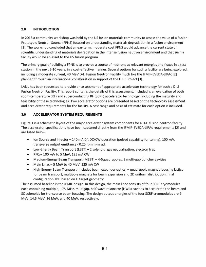
In 2018 a community workshop was held by the US fusion materials community to assess the value of a Fusion Prototypic Neutron Source (FPNS) focused on understanding materials degradation in a fusion environment [1]. The workshop concluded that a near-term, moderate cost FPNS would advance the current state of scientific understanding of materials degradation in the intense fusion neutron environment and that such a facility would be an asset to the US fusion program.
The primary goal of building a FPNS is to provide a source of neutrons at relevant energies and fluxes in a test station in the next 5-10 years, in a cost-effective manner. Several options for such a facility are being explored, including a moderate current, 40 MeV D-Li Fusion Neutron Facility much like the IFMIF-EVEDA-LIPAc [2] planned through an international collaboration in support of the ITER Project [3].
LANL has been requested to provide an assessment of appropriate accelerator technology for such a D-Li Fusion Neutron Facility. This report contains the details of this assessment. Included is an evaluation of both room-temperature (RT) and superconducting RF (SCRF) accelerator technology, including the maturity and feasibility of these technologies. Two accelerator options are presented based on the technology assessment and accelerator requirements for the facility. A cost range and basis of estimate for each option is included.
3.0 ACCELERATOR SYSTEM REQUIREMENTS
Figure 1 is a schematic layout of the major accelerator system components for a D-Li fusion neutron facility. The accelerator specifications have been captured directly from the IFMIF-EVEDA-LIPAc requirements [2] and are listed below:
• Ion Source and Injector – 140 mA D+, DC/CW operation (pulsed capability for tuning), 100 keV, transverse output emittance <0.25 π-mm-mrad.
• Low-Energy Beam Transport (LEBT) – 2 solenoid, gas neutralization, electron trap • RFQ – 100 keV to 5 MeV, 125 mA CW • Medium-Energy Beam Transport (MEBT) – 4-5quadrupoles, 2 multi-gap buncher cavities • Main Linac – 5 MeV to 40 MeV, 125 mA CW • High-Energy Beam Transport (includes beam expander optics) – quadrupole magnet focusing lattice
for beam transport, multipole magnets for beam expansion and 2D uniform distribution, final configuration TBD based on Li target geometry.
The assumed baseline is the IFMIF design. In this design, the main linac consists of four SCRF cryomodules each containing multiple, 175-MHz, multigap, half-wave resonator (HWR) cavities to accelerate the beam and SC solenoids for transverse beam focusing. The design output energies of the four SCRF cryomodules are 9 MeV, 14.5 MeV, 26 MeV, and 40 MeV, respectively.

B-5
Figure 1 – Schematic layout of a generic 40-MeV, D+ linac for D-Li neutron production.
4.0 ANALYSIS OF ALTERNATIVES (AOA)
Several alternative accelerator designs were proposed in the recent past for a D-Li fusion neutron facility to generate 14-MeV neutrons. These proposed accelerator designs included both normal-conducting and superconducting main accelerators following a RFQ accelerator for initial acceleration of the D+ beam. The IFMIF project has selected superconducting accelerator technology using half-wave resonators as the baseline for their main linac. However, since a major goal of this assessment is to develop a cost-effective solution that also meets the performance requirements for a moderate-energy D-Li fusion neutron facility, several past designs have been evaluated and will be used to propose options for the proposed US facility.
As the beam power increases and becomes comparable to the RF structure power required (high beam loading), the use of normal-conducting accelerator structures becomes more attractive and may lead to a lower-cost option as compared to using SCRF technology. This is particularly the case for a relatively low-energy accelerator. High-energy accelerators such as the Spallation Neutron Source (SNS) [4] or the European Spallation Source (ESS) [5] benefit from the use of SCRF. For these facilities the advantages of SCRF are realized primarily as overall power savings due to the final high beam energy (>1 GeV) and from the large apertures that reduce beam losses at high energy where these losses have the highest beam powers. However, both the SNS and ESS use NC accelerators initially up to approximately 100 MeV beam energy for efficiency of beam capture and acceleration.
The most relevant alternative designs include initial designs proposed at LANL including modification and reuse of the Low-Energy Demonstration Accelerator (LEDA), an early design agreed to by consensus of the fusion and accelerator communities (FMIF), and the presently accepted IFMIF design. Details of each of these alternatives are included in the subsections below. These alternatives are also the basis of estimate of costs for the options proposed in Section 5.0.
4.1 LANL High-Flux Accelerator-Based Neutron Source for Fusion Materials and Technology Testing (1989)
An accelerator design concept for a high-flux accelerator based neutron source for fusion materials and technology testing was presented by LANL in 1989 at the IFMIF Workshop in San Diego, CA [6]. This proposed design is based on the Fusion Materials Irradiation Test (FMIT) Facility with additional improvements. Table 1 summarizes the accelerator parameters for this design.

B-6
Accelerator technology improvements incorporated since FMIT include:
• A better analytical understanding of emittance growth, space-charge effects, and halo reduction. • Use of ramped linac accelerating gradients to preserve longitudinal beam emittance. • Use of permanent-magnet quadrupoles (PMQs) to provide strong low-energy focusing, preserving
transverse beam emittance. • Use of higher RF frequencies to reduce beam emittance growth (lower charge per micropulse) and to
allow more compact accelerating structures. • Use of improved beam-dynamics and high-order optics codes for simulating high-current beams and
for controlling the spatial intensity of the beam, respectively. It should be noted that these improvements have become standard practice in designing most modern high-power accelerators.
This design assumes 100-keV injection into a 3-MeV 175-MHz RFQ followed by a NC 35-MeV 350-MHz DTL. The DTL operating frequency was doubled under the assumption that beam funneling of two RFQ accelerators would be required if higher beam currents (x2) were desired. The DTL is assumed to have 4 tanks that allow energy variations in discrete steps of the final output beam energy (20, 25, 30, and 35 MeV) to the lithium target test region. The HEBT contains a beam expander based on a single octupole magnet followed by a defocusing quadrupole/focusing quadrupole magnet combination for setting the final beam size and distribution, generating a nearly uniform, rectangular beam distribution at the target. The accelerator design specifications presented are supported by beam physics or engineering design calculations.
The 1989 report highlights several accelerator technical issues:
• Beam losses in the accelerator and HEBT – activation levels need to allow for hands-on maintenance (10-6/m). This is the goal of all modern accelerator designs.
• Accelerator Efficiency – RF costs dominant overall accelerator costs. Design should include cost optimization.
• Beam Energy Variability – Design uses a DTL as the main accelerating structure. This allows only discrete output beam energies by turning off DTL tanks or operating RF out of time. Small energy increments are possible by actively rotating DTL individual post couplers in a DTL tank, however this adds complexity and may increase beam losses.
Cost information was provided and the estimated cost of the full fusion materials and technology facility is $352M (2019$) based on escalating the cited costs in Ref. 6 by 3% per year. Estimated cost of the accelerator system is $85M (2019$). Details of the costing can be found in Section 6.

B-7
Table 1 – Accelerator specifications for the proposed High-Flux Accelerator-Based Neutron Source for Fusion Materials and Technology Testing.
Ion Source Species D+ Output Beam Current (mA) 140 Output Energy (MeV) 0.100 Output Transverse Emittance (π-mm-mrad, rms, norm) Not available
Low-Energy Beam Transport (LEBT) 2-Solenoid LEBT with gas neutralization and electron trap
RFQ Type 4-vane RF Frequency (MHz) 175 Input Energy (MeV) 0.100 Output Energy (MeV) 3.0 Input Beam Current (mA) 140 Output Beam Current (mA) 125 Beam Power (MW) 0.36 Structure Power (MW) 0.3 Total RF Power (MW) 0.66 Beam Loading (%) 55 Output Transverse Emittance (π-mm-mrad, rms, norm) 0.27 Output Longitudinal Emittance (π-mm-mrad, rms, norm) 0.46 Structure Length (m) 5.4
Medium Energy Beam Transport (MEBT) Quadrupole Magnets 4 Bunchers 2, 175-MHz multi-gap cavities MEBT Length (m) Not available
Main Accelerator Structure Type DTL RF Frequency (MHz) 350 Input Energy (MeV) 3.0 Output Energy (MeV) 35.0 No. Structure Segments 4 Input Beam Current (mA) 125 Output Beam Current (mA) 125 Beam Power (MW) 4.0 Structure Power (MW) 3.3 Total RF Power (MW) 7.3 Beam Loading (%) 55 Transverse Focusing Type Quadrupole magnets Quadrupole Gradients (T/m) 120.0-100.0 Output Transverse Emittance (π-mm-mrad, rms, norm) 0.30 Output Longitudinal Emittance (π-mm-mrad, rms, norm) 0.51 Accelerating Gradient (MV/m) 3.0-4.0 Structure Length (m) 13
High-Energy Beam Transport (HEBT) Beam Expander - Octupole, D-quad, F-quad
RF Systems RFQ – 175 MHz Tetrode, DTL – 350 MHz Klystron

B-8
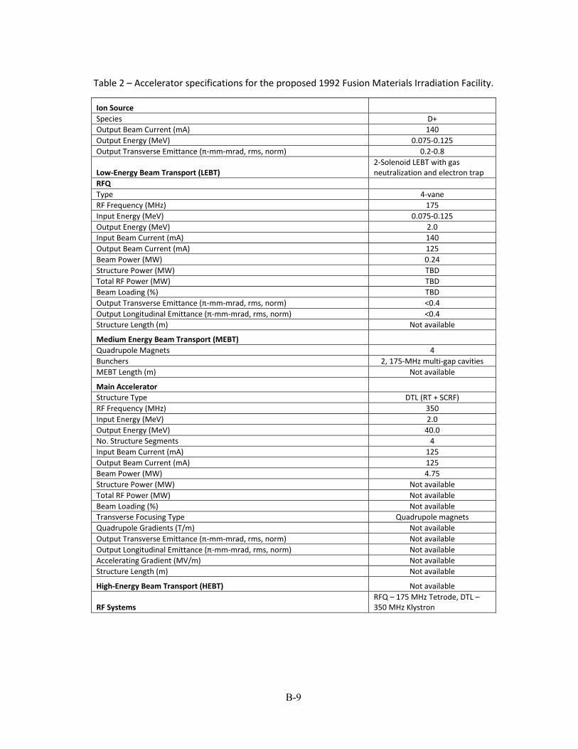
4.2 Fusion Materials Irradiation Facility (FMIF 1992)
A draft report was issued in 1992 by the FMIF Working Group [7] that established accelerator design specifications for a 14-MeV fusion materials irradiation facility capable of providing a neutron flux equivalent to a neutron wall loading of 2 MW/m2 to a 1-liter irradiation volume. The accelerator design specifications proposed are very similar to those proposed by LANL in 1989 with a few differences.
This design assumes 100-keV injection into a 2-MeV 175-MHz RFQ followed by a hybrid NC-SCRF 40-MeV, 350-MHz DTL. The DTL operating frequency was doubled under the assumption that beam funneling of two RFQ accelerators would be required if higher beam currents (x2) were desired due to ion source limitations. The DTL design uses four tanks that allow energy variations in discrete steps of the final output beam energy (8, 30, 35, and 40 MeV) delivered to the lithium-target test region. The DTL is divided into two major sections: Section 1 is a NC 350-MHz DTL accelerating the beam to 8 MeV. Section 2 contains three 350-MHz SCRF DTL sections accelerating the beam to the final 40-MeV energy. Beam energy variability is provided by changing the operating parameters of the SCRF DTL sections. The HEBT provides magnetic focusing for beam transport to a beam dump for tuning and target safety, and also contains a beam expander for setting the final beam size and distribution at the target. Table 2 summarizes the accelerator parameters for this design.
The accelerator design specifications presented are not supported by beam physics or engineering design calculations. Additionally, no cost information was provided.
4.3 LANL LEDA (2003)
A study was done in 2003 on the potential use of the LANL Low-Energy Demonstration Accelerator (LEDA) Facility for initial testing of Fusion Materials [8]. Two options were presented, both of which used the LEDA RFQ in modified form as the first stage of D+ beam acceleration. Superconducting accelerating cavities follow the RFQ to accelerate the beam to the final 40-MeV beam energy. Although not specified, it is assumed that the SCRF cavities proposed would be 350-MHz multi-gap spoke resonators based on the Accelerator Production of Tritium (APT) [9] cavity designs. It is assumed that these SCRF designs were also used as the basis of the costs quoted. These costs seem high in comparison to other alternatives based on the limited cost details available. Currently the LEDA RFQ is in storage at LANL minus the ion source/injector and could potentially be available for repurposing for a new 14-MeV D-Li fusion neutron facility.
Table 3 summarizes the two options investigated based on upgrading the LEDA RFQ. The first option provides a 50-mA deuterium beam, limited by the RFQ transmission at 350 MHZ, by changing the vanes in the RFQ to support efficient D+ acceleration while still operating at the original 350-MHz RF frequency. This option would have allowed for reuse of the then-existing 350-MHz APT klystrons, however these klystrons have since been salvaged and are no longer available. The estimated cost of the accelerator upgrade is $152M (2019$).
The second option is based on the requirement to generate a 125-mA 40-MeV D+ beam. This option requires building a new RFQ operating at 175 MHz to allow for higher beam transmission in the RFQ and a new associated 175-MHz RF system. This option, like the first, assumes the use of 350-MHz multi-gap spoke resonators following the RFQ to reach 40 MeV. Cost of this option is significantly higher due to the added cost of the new RFQ and RF system. The estimated accelerator cost is $209M (2019$) based on escalating costs 3% per year.
B-9
Table 2 – Accelerator specifications for the proposed 1992 Fusion Materials Irradiation Facility.
Ion Source Species D+ Output Beam Current (mA) 140 Output Energy (MeV) 0.075-0.125 Output Transverse Emittance (π-mm-mrad, rms, norm) 0.2-0.8
Low-Energy Beam Transport (LEBT) 2-Solenoid LEBT with gas neutralization and electron trap
RFQ Type 4-vane RF Frequency (MHz) 175 Input Energy (MeV) 0.075-0.125 Output Energy (MeV) 2.0 Input Beam Current (mA) 140 Output Beam Current (mA) 125 Beam Power (MW) 0.24 Structure Power (MW) TBD Total RF Power (MW) TBD Beam Loading (%) TBD Output Transverse Emittance (π-mm-mrad, rms, norm) <0.4 Output Longitudinal Emittance (π-mm-mrad, rms, norm) <0.4 Structure Length (m) Not available
Medium Energy Beam Transport (MEBT) Quadrupole Magnets 4 Bunchers 2, 175-MHz multi-gap cavities MEBT Length (m) Not available
Main Accelerator Structure Type DTL (RT + SCRF) RF Frequency (MHz) 350 Input Energy (MeV) 2.0 Output Energy (MeV) 40.0 No. Structure Segments 4 Input Beam Current (mA) 125 Output Beam Current (mA) 125 Beam Power (MW) 4.75 Structure Power (MW) Not available Total RF Power (MW) Not available Beam Loading (%) Not available Transverse Focusing Type Quadrupole magnets Quadrupole Gradients (T/m) Not available Output Transverse Emittance (π-mm-mrad, rms, norm) Not available Output Longitudinal Emittance (π-mm-mrad, rms, norm) Not available Accelerating Gradient (MV/m) Not available Structure Length (m) Not available
High-Energy Beam Transport (HEBT) Not available
RF Systems RFQ – 175 MHz Tetrode, DTL – 350 MHz Klystron

B-10
Table 3 – Two proposed SCRF LEDA-based accelerator options to generate a 40-MeV D+ beam.
LEDA Option 1 LEDA Option 2
Ion Source
Species D+ D+ Output Beam Current (mA) 140 140 Output Energy (MeV) 0.075 0.075 Output Transverse Emittance (π-mm-mrad, rms, norm) 0.3 0.3
Low-Energy Beam Transport (LEBT)
2-Solenoid LEBT with gas neutralization and electron trap
2-Solenoid LEBT with gas neutralization and electron trap
RFQ Type 4-vane 4-vane RF Frequency (MHz) 350 175 Input Energy (MeV) 0.075 0.075 Output Energy (MeV) 6.7 6.7 Input Beam Current (mA) 140 140 Output Beam Current (mA) 50 125 Beam Power (MW) 0.33 0.825 Structure Power (MW) Not available Not available Total RF Power (MW) Not available Not available Beam Loading (%) Not available Not available Output Transverse Emittance (π-mm-mrad, rms, norm) <0.4 <0.4 Output Longitudinal Emittance (π-mm-mrad, rms, norm) <0.4 <0.4 Structure Length (m) 8.0 8.0
Medium Energy Beam Transport (MEBT)
Quadrupole Magnets 4 4 Bunchers 2, 350-MHz multi-gap cavities 2, 350-MHz multi-gap cavities MEBT Length (m) TBD TBD
Main Accelerator
Structure Type SCRF Multi-gap Spokes SCRF Multi-gap Spokes RF Frequency (MHz) 350 350 Input Energy (MeV) 6.7 6.7 Output Energy (MeV) 40.0 40.0 No. Structure Segments Not available Not available Input Beam Current (mA) 125 125 Output Beam Current (mA) 125 125 Beam Power (MW) 1.67 4.16 Structure Power (MW) Not available Not available Total RF Power (MW) Not available Not available Beam Loading (%) Not available Not available Transverse Focusing Type Quadrupole magnets Quadrupole magnets Quadrupole Gradients (T/m) Not available Not available Output Transverse Emittance (π-mm-mrad, rms, norm) Not available Not available Output Longitudinal Emittance (π-mm-mrad, rms, norm) Not available Not available Accelerating Gradient (MV/m) Not available Not available Structure Length (m) Not available Not available
High-Energy Beam Transport (HEBT) Not available Not available
RF Systems RFQ, DTL – 350 MHz Klystrons RFQ – 175 MHz Tetrode, DTL – 350 MHz Klystrons
B-11
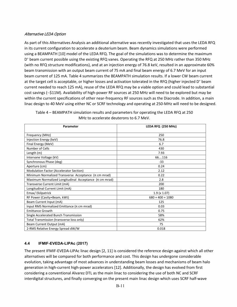
Alternative LEDA Option
As part of this Alternatives Analysis an additional alternative was recently investigated that uses the LEDA RFQ in its current configuration to accelerate a deuterium beam. Beam dynamics simulations were performed using a BEAMPATH [10] model of the LEDA RFQ. The goal of the simulations was to determine the maximum D+ beam current possible using the existing RFQ vanes. Operating the RFQ at 250 MHz rather than 350 MHz (with no RFQ structure modifications), and at an injection energy of 76.8 keV, resulted in an approximate 60% beam transmission with an output beam current of 75 mA and final beam energy of 6.7 MeV for an input beam current of 125 mA. Table 4 summarizes the BEAMPATH simulation results. If a lower CW beam current at the target cell is acceptable, or higher losses and activation tolerated in the RFQ (higher injected D+ beam current needed to reach 125 mA), reuse of the LEDA RFQ may be a viable option and could lead to substantial cost savings (⁓$11M). Availability of high-power RF sources at 250 MHz will need to be explored but may be within the current specifications of other near-frequency RF sources such as the Diacrode. In addition, a main linac design to 40 MeV using either NC or SCRF technology and operating at 250-MHz will need to be designed.
Table 4 – BEAMPATH simulation results and parameters for operating the LEDA RFQ at 250 MHz to accelerate deuterons to 6.7 MeV.
Parameter
LEDA RFQ (250 MHz)
Frequency (MHz) 250 Injection Energy (keV) 76.8 Final Energy (MeV) 6.7 Number of Cells 430 Length (m) 7.93 Intervane Voltage (kV) 66….116 Synchronous Phase (deg) -33 Aperture (cm) 0.24 Modulation Factor (Accelerator Section) 2.12 Minimum Normalized Transverse Acceptance (π cm mrad) 0.22 Maximum Normalized Longitudinal Acceptance (π cm mrad) 2.8 Transverse Current Limit (mA) 200 Longitudinal Current Limit (mA) 180 Emax/ Ekilpatrick 1.9 (x 1.07) RF Power (Cavity+Beam, kWt) 680 + 400 = 1080 Beam Current Input (mA) 125 Input RMS Normalized Emittance (π cm mrad) 0.03 Emittance Growth 0.75 Single Accelerated Bunch Transmission 58% Total Transmission (transverse loss only) 62% Beam Current Output (mA) 75 2-RMS Relative Energy Spread dW/W 0.018
4.4 IFMIF-EVEDA-LIPAc (2017)
The present IFMIF-EVEDA-LIPAc linac design [2, 11] is considered the reference design against which all other alternatives will be compared for both performance and cost. This design has undergone considerable evolution, taking advantage of most advances in understanding beam losses and mechanisms of beam halo generation in high-current high-power accelerators [12]. Additionally, the design has evolved from first considering a conventional Alvarez DTL as the main linac to considering the use of both NC and SCRF interdigital structures, and finally converging on the present main linac design which uses SCRF half-wave

B-12
resonators (HWRs) [13]. Use of a SCRF linac substantially reduces the required RF power and the future facility operating cost. Figure 2 shows a schematic layout of the IFMIF-EVEDA-LIPAc linac design. Table 5 summarizes the accelerator parameters for a single-linac system.
Figure 2 – Schematic layout of the proposed IFMIF-EVEDA-LIPAc linac design [12].
Estimated cost of the 40-MeV IFMIF-EVEDA-LIPAc linac system is unknown due to the unavailability of cost information. As of 2007, $219.9M (2019$) was budgeted for the project including the 9-MeV LIPAc demonstration using available IFMIF cost conversions and assuming in-kind contributions from the international collaboration [14].
4.5 Summary of Design Alternatives
Table 6 provides a brief summary and comparison of the design alternatives reviewed. The differences highlighted are the differences in accelerator technology used for each design, the specific energy transitions between accelerator types, the total power required for each system and the estimated cost. Each of these systems meet the requirements for a 14-MeV D-Li Fusion Neutron irradiation facility.
5.0 ACCELERATOR OPTIONS
Based on the analysis of alternatives, several viable accelerator options exist. Two options are presented below. Option 1 directly reproduces the present SCRF based IFMIF design based on costs to design and fabricate the accelerator in the US with some potential foreign vendor participation. Option 2 replaces the SCRF linac with a NC DTL as an alternative option that may have some operational advantages. Other combinations are certainly possible based on cost and complexity. Both options assume there will be no access to IFMIF design information, requiring the design of all accelerator components to be completed by ORNL, another partner laboratory, or a commercial accelerator vendor. A potential RFQ design is based on the successful design principles used to design the LANL LEDA RFQ. This design has not been optimized but is included as an example in the options presented. All RFQ design parameters and simulation results are based on extending the LEDA RFQ design to 175 MHZ (from 350 MHz) to efficiently accelerate a 125-mA D+ beam. All quoted costs were derived using the basis of estimate information in Section 6.

B-13
Table 5 – Accelerator specifications for the present IFMIF-EVEDA-LIPAc linac design.
Ion Source Species D+ Output Beam Current (mA) 140 Output Energy (MeV) 0.100 Output Transverse Emittance (π-mm-mrad, rms, norm) <0.3
Low-Energy Beam Transport (LEBT) 2-Solenoid LEBT with gas neutralization and electron trap
RFQ Type 4-vane RF Frequency (MHz) 175 Input Energy (MeV) 0.100 Output Energy (MeV) 5.0 Input Beam Current (mA) 140 Output Beam Current (mA) 125 Beam Power (MW) 0.61 Structure Power (MW) 0.56 Total RF Power (MW) 1.18 Beam Loading (%) 52 Output Transverse Emittance (π-mm-mrad, rms, norm) 0.31 Output Longitudinal Emittance (π-mm-mrad, rms, norm) <0.4 Structure Length (m) 9.6
Medium Energy Beam Transport (MEBT) Quadrupole Magnets 5 Bunchers 2, 5-gap IH cavities MEBT Length (m) 2
Main Accelerator Structure Type SC 2-gap HWR RF Frequency (MHz) 175 Input Energy (MeV) 5.0 Output Energy (MeV) 40.0 No. Structure Segments 4 Cryomodules
Cavity Design β β=0.094, β=0.094, β=0.164, β=0.164
No. Cavities per Cryomodule Cryomodules 1,2 = 6 Cryomodules 3,4 = 4
Cryomodule output energy (MeV) 9.0, 14.5, 26.0, 40.0 Input Beam Current (mA) 125 Output Beam Current (mA) 125 Beam Power (MW) 4.4 Structure Power (MW) 0.18 Total RF Power (MW) 5.58 Beam Loading (%) 79 Transverse Focusing Type SC EM Solenoids Output Transverse Emittance (π-mm-mrad, rms, norm) 0.3 Output Longitudinal Emittance (π-mm-mrad, rms, norm) Not available Accelerating Gradient (MV/m) 4.5 Structure Length (m) 22.7
High-Energy Beam Transport (HEBT) Not available
RF Systems 48 220 kW, 175 MHz Tetrodes

B-14
Table 6 – Summary of reviewed design alternatives.
High-Flux Source
(1989) FMIF (1992) LEDA (2003) IFMIF-EVEDA-
LIPAc (2017)
Ion Source
Species D+ D+ D+ D+ Output Beam Current (mA) 140 140 140 140 Output Energy (MeV) 0.100 0.075-0.125 0.075 0.100 RFQ Type 4-vane 4-vane 4-vane 4-vane RF Frequency (MHz) 175 175 350 or 175 175 Input Energy (MeV) 0.100 0.075-0.125 0.075 0.100 Output Energy (MeV) 3.0 2.0 6.7 5.0 Input Beam Current (mA) 140 140 140 140 Output Beam Current (mA) 125 125 50-125 125 Beam Power (MW) 0.36 0.24 0.33-0.825 0.61 Structure Power (MW) 0.30 0.2 (estimated) Not available 0.56 Total RF Power (MW) 0.66 0.44 - 1.17 Beam Loading (%) 55 55 - 52 Structure Length (m) 5.4 Not available 8.0 9.6
Main Accelerator Structure Type DTL DTL DTL or SCRF SC 2-gap HWR RF Frequency (MHz) 350 350 175 or 350 175 Input Energy (MeV) 3.0 2.0 6.7 5.0 Output Energy (MeV) 35.0 40.0 40.0 40.0 Output Beam Current (mA) 125 125 125 125 Beam Power (MW) 4.0 4.75 1.67-4.16 4.4 Structure Power (MW) 3.3 3.92 (estimated*) Not available 0.18 Total RF Power (MW) 7.3 8.7 - 5.58 Beam Loading (%) 55 Not available Not available 79 Accelerating Gradient (MV/m) 3.0-4.0 Not available Not available 4.5 Structure Length (m) 13.0 Not available Not available 22.7
Total RF Power (MW) 7.96 9.14 (estimated*) - 5.75
RF Systems 175 MHz Tetrodes
RFQ – 175 MHz Tetrode, DTL – 350
MHz Klystron 175 MHz Tetrode, 350 MHz Klystron
48 - 220 kW, 175 MHz Tetrodes
Cost (2019$) $85M Not available $152M-$209M Not available *Estimated by scaling 1989 results by energy.
5.1 Option 1: Radiofrequency Quadrupole (RFQ) + Superconducting RF (SCRF) Linac
Option 1 essentially reproduces the IFMIF-EVEDA-LIPAc linac design using a LEDA-based RFQ and a similar SCRF linac using HWR cavities. Figure 3 shows a schematic layout of this option. Table 7 summarizes the general RFQ and SCRF linac parameters. The RFQ output energy is 5-MeV, but cost tradeoffs based on alternative RFQ lengths and final output energies could be considered to optimize the overall linac costs. Also shown are preliminary RFQ simulation results (see Table 8 and Fig. 4) used to estimate the total RF structure power required. Table 9 summarizes the estimated average cost by subsystem for the largest system cost components: the RFQ, the SCRF linac, the RF system, and the cryoplant based on the cost scaling factors developed in Section 6 below. Estimated costs do not include institutional overheads.

B-15
Figure 3 – Option 1 schematic layout.
Table 7 – Option 1 accelerator specifications.
Ion Source Species D+ Output Beam Current (mA) 140 Output Energy (MeV) 0.100 Output Transverse Emittance (π-mm-mrad, rms, norm) <0.3
Low-Energy Beam Transport (LEBT) 2-Solenoid LEBT with gas neutralization and electron trap
RFQ (LEDA Based) Type 4-vane RF Frequency (MHz) 175 Input Energy (MeV) 0.100 Output Energy (MeV) 5.0 Input Beam Current (mA) 140 Output Beam Current (mA) 125 Beam Power (MW) 0.61 Structure Power (MW) 0.56 Total RF Power (MW) 1.17 Output Transverse Emittance (π-mm-mrad, rms, norm) 0.30 Output Longitudinal Emittance (π-mm-mrad, rms, norm) <0.4 Structure Length (m) 9.6
Medium Energy Beam Transport (MEBT) Quadrupole Magnets 5 Bunchers 2, 5-gap IH cavities MEBT Length (m) 2
Main Accelerator Structure Type SC 2-gap HWR RF Frequency (MHz) 175 Output Energy (MeV) 40.0 No. Structure Segments 4 Cryomodules
Cavity Design β β=0.094, β=0.094, β=0.164, β=0.164
No. Cavities per Cryomodule Cryomodules 1,2 = 6 Cryomodules 3,4 = 4
Cryomodule output energy (MeV) 9.0, 14.5, 26.0, 40.0 Output Beam Current (mA) 125 Beam Power (MW) 4.4 Structure Power (MW) 0.2 Total RF Power (MW) 4.6 Transverse Focusing Type SC EM Solenoids Output Transverse Emittance (π-mm-mrad, rms, norm) 0.3 Structure Length (m) 22.7 Total RF Power – RFQ + SCRF Linac (MW) 5.8

B-16
Figure 4 – Beam simulation results for a 175-MHz LEDA-scaled D+ RFQ.

B-17
Table 8 – Simulation results for a 175-MHz LEDA-scaled D+ RFQ.
Parameter Value Frequency (MHz) 175 Injection Energy (keV) 100 Final Energy (MeV) 5 Number of Cells 360 Length (m) 7.83 Intervane Voltage (kV) 88….136 Synchronous Phase (deg) -35 Aperture (cm) 0.4 Max Modulation Factor 2.12 End-of-Buncher Norm Transv Acceptance (π cm mrad) 0.4 End-of-Buncher Norm Long Acceptance (π cm mrad) 1.0 Transverse Current Limit (A) 0.3 Longitudinal Current Limit (A) 0.3 Emax/ Ekilpatrick 1.85 (x 1.07) RF Power (Cavity + Beam, kWt) 564+550 = 1114 Beam Current Input (mA) 125 Input RMS Norm Emittance (π cm mrad) 0.03 Emittance Growth Factor 1.0 Single Accelerated Bunch Transmission (%) 88.6 Total Transmission (transverse loss only; %) 90.0 2-RMS Relative Energy Spread dW/W 8.84 x 10⁻³
Table 9 – Option 1 Cost Summary by Subsystem
Subsystem 2019 Cost ($M) Basis of Estimate RFQ (175 MHz) 11.28 Low cost/m from 1989 IFMIF; High cost/m from IFMIF-EVEDA project SCRF HWR (175 MHz)
34.05 SARAF cost/m
RF Power 19.94 Low cost/MW from SARAF Project; High cost/MW from 1989 High Flux Source Cryoplant 8.50 MSU/FRIB Total 73.76

B-18
5.2 Option 2: Radiofrequency Quadrupole (RFQ) + Normal-Conducting (NC) Linac
Option 2 consists of a 175-MHz, 5-MeV, LEDA-based RFQ followed by a 175-MHz, NC Alvarez-type DTL to 40 MeV. Table 10 summarizes the general RFQ and DTL linac parameters for this option. A schematic layout is shown in Fig. 5. Just as for Option 1, cost tradeoffs based on alternative RFQ lengths and final output energies could be considered to optimize the overall linac costs.
Table 10 – Option 2 accelerator specifications.
Ion Source Species D+ Output Beam Current (mA) 140 Output Energy (MeV) 0.100 Output Transverse Emittance (π-mm-mrad, rms, norm) <0.3
Low-Energy Beam Transport (LEBT) 2-Solenoid LEBT with gas neutralization and electron trap
RFQ (LEDA Based) Type 4-vane RF Frequency (MHz) 175 Input Energy (MeV) 0.100 Output Energy (MeV) 5.0 Input Beam Current (mA) 140 Output Beam Current (mA) 125 Beam Power (MW) 0.61 Structure Power (MW) 0.56 Total RF Power (MW) 1.17 Output Transverse Emittance (π-mm-mrad, rms, norm) 0.30 Output Longitudinal Emittance (π-mm-mrad, rms, norm) <0.4 Structure Length (m) 9.6
Medium Energy Beam Transport (MEBT) Quadrupole Magnets 4 Bunchers 2, 175-MHz, 2-gap cavities MEBT Length (m) 2
Main Accelerator Structure Type NC DTL RF Frequency (MHz) 175 Output Energy (MeV) 40.0 No. Structure Segments TBD Output Beam Current (mA) 125 Beam Power (MW) 4.4 Structure Power (MW) 2.0 Total RF Power (MW) 6.4 Transverse Focusing Type Permanent-Magnet Quadrupoles Output Transverse Emittance (π-mm-mrad, rms, norm) 0.3 Structure Length (m) 23 Total RF Power – RFQ + SCRF Linac (MW) 7.6

B-19
Figure 5 – Option 2 schematic layout.
Preliminary design simulation results estimate the DTL structure power required, the total length of the DTL structure, and the beam dynamics performance (emittance growth, transmission, etc.). These results are summarized in Table 11 below. The proposed DTL accelerating gradient is 1.75 MV/m and the nominal operating synchronous phase of the beam is -30 deg. This results in an overall DTL structure length of 23 m and a total structure power of approximately 2 MW. Figure 6 shows the preliminary structure calculation results including the DTL cell and drift-tube geometries assumed. A lower accelerating gradient was selected to maintain a reasonable total structure power as a trade-off with overall DTL length. It is assumed that accelerator tunnel length costs are significantly lower per meter than are high-power RF costs per MW. However, these parameters and associated costs can be optimized during a more detailed design study. Figure 7 summarizes additional DTL design simulation results.
Table 12 summarizes the estimated average cost by subsystem for the largest system cost components: the RFQ, the NC DTL, and the RF system based on the cost scaling factors developed in Section 6 below. Estimated costs do not include institutional overheads.
Table 11 – Simulation results for a 175-MHz D+ NC DTL.
Parameter Value Frequency (MHz) 175 Injection Energy (MeV) 5 Final Energy (MeV) 40 Structure Type Alvarez (0-mode) Focusing Period 2βλ Number of Accelerating Gaps 98 Length (m) 23.36 Accelerating Gradient (MV/m) 1.75 Transit Time Factor 0.9-0.95 Synchronous Phase (deg) -30 Aperture (cm) 1.0 Quadrupole Accelerating Gradient (T/cm) 0.8-0.75 Norm Transv Acceptance (π cm mrad) 3.35 Norm Long Acceptance (π cm mrad) 2.29 RF Power (Cavity + Beam, MW) 2.0+3.9 = 5.9 Beam Current Input (mA) 125 Input RMS Norm Emittance (π cm mrad) 0.03 Emittance Growth Factor 1.14 Single Accelerated Bunch Transmission (%) 99.97 Total Transmission (transverse loss only; %) 99.97 2-RMS Relative Energy Spread dW/W 3.3 x 10⁻³

B-20
Figure 6 – Preliminary structure simulation results for Option 2.
Figure 7 – Beam simulation results for a 175-MHz NC D+ DTL.

B-21
Table 12 – Option-2 Cost Summary by Subsystem
Subsystem 2019 Cost ($M) Basis of Estimate RFQ (175 MHz) 11.28 Low cost/m from 1989 IFMIF; High cost/m from IFMIF-EVEDA project DTL (175 MHz) 32.82 Low cost/m from 1989 High Flux Source; high cost/m from 1996 IFMIF design
pre-SCRF assuming DTL RF Power 26.15 Low cost/MW from SARAF Project; High cost/MW from 1989 High Flux Source Total 70.25
6.0 COST ESTIMATE – BASIS OF ESTIMATE
A cost estimate for each accelerator option in Section 5 was developed using information from three primary sources [6, 15, 16]. Cost information from these sources was appropriately escalated using a 3%/year escalation rate to determine 2019 estimated costs. Individual estimates were developed for the six major accelerator subsystems contributing to the majority of the integrated accelerator cost for a 40-MeV fusion neutron facility based on the overall accelerator layout: 1) the RFQ, 2) a SCRF linac, 3) a NC DTL, 4) the HEBT, 5) the RF system, and 6) the cryoplant. This allows the flexibility to estimate additional combinations of subsystem technology if desired. In the case where several bases of estimate are available for a subsystem, cost scaling factors are used that reflect the average cost per unit for each subsystem.
6.1 IFMIF Accelerator Equipment Cost Summary (1996)
A site-independent online accelerator system cost summary developed in December 1996 is available at http://www.frascati.enea.it/cda/CostReport/ [15]. This cost estimate integrates the in-kind contributions due to the international partnership of the IFMIF collaboration as defined at the time of the report. In 1996, the IFMIF design was based on using a NC DTL as the main linac. Costs have been normalized using a unique cost unit called the “IFMIF Conversion Factor (ICF)” where 1 ICF = $1.00 US (1996). Table 7 summarizes the accelerator equipment costs for a single 125-mA, D+, NC linac (RFQ+ DTL) using this methodology.
The overall costs in Ref 15 are subdivided into “Off Site” costs that include all accelerator equipment costs minus “On Site” installation and commissioning. The accelerator equipment costs are further subdivided by first and second accelerator system. The accelerator equipment costs associated with building the first unit are higher, compared to the second system that takes advantage of recurring engineering. The higher cost data was used to estimate the cost scaling factors shown in Table 13 after being appropriately escalated by 3%/year from 1996 to 2019.
Table 13 – 1996 IFMIF Accelerator Equipment Cost Summary by Subsystem
Subsystem 1992 Cost 2019 Cost RFQ (175 MHz) $11.6M $22.9M DTL (175 MHz) $22.4M $44.2M HEBT $13.4M $26.5M RF Power $63.5M $125.3M
Based on the escalated costs of Table 8, the following scale factors have been derived in $M 2019:
• 175-MHz RFQ structure cost/meter = $2.39M/meter
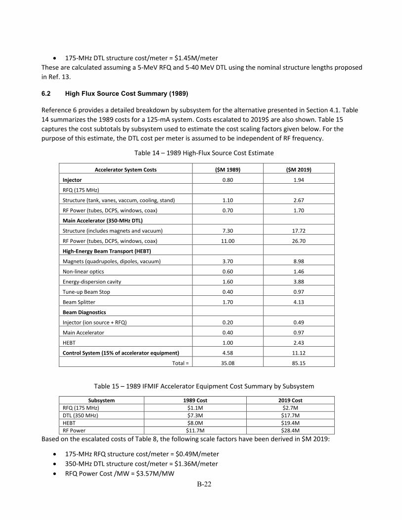
B-22
• 175-MHz DTL structure cost/meter = $1.45M/meter These are calculated assuming a 5-MeV RFQ and 5-40 MeV DTL using the nominal structure lengths proposed in Ref. 13.
6.2 High Flux Source Cost Summary (1989)
Reference 6 provides a detailed breakdown by subsystem for the alternative presented in Section 4.1. Table 14 summarizes the 1989 costs for a 125-mA system. Costs escalated to 2019$ are also shown. Table 15 captures the cost subtotals by subsystem used to estimate the cost scaling factors given below. For the purpose of this estimate, the DTL cost per meter is assumed to be independent of RF frequency.
Table 14 – 1989 High-Flux Source Cost Estimate
Accelerator System Costs ($M 1989) ($M 2019)
Injector 0.80 1.94
RFQ (175 MHz) Structure (tank, vanes, vaccum, cooling, stand) 1.10 2.67
RF Power (tubes, DCPS, windows, coax) 0.70 1.70
Main Accelerator (350-MHz DTL) Structure (includes magnets and vacuum) 7.30 17.72
RF Power (tubes, DCPS, windows, coax) 11.00 26.70
High-Energy Beam Transport (HEBT) Magnets (quadrupoles, dipoles, vacuum) 3.70 8.98
Non-linear optics 0.60 1.46
Energy-dispersion cavity 1.60 3.88
Tune-up Beam Stop 0.40 0.97
Beam Splitter 1.70 4.13
Beam Diagnostics Injector (ion source + RFQ) 0.20 0.49
Main Accelerator 0.40 0.97
HEBT 1.00 2.43
Control System (15% of accelerator equipment) 4.58 11.12
Total = 35.08 85.15
Table 15 – 1989 IFMIF Accelerator Equipment Cost Summary by Subsystem
Subsystem 1989 Cost 2019 Cost RFQ (175 MHz) $1.1M $2.7M DTL (350 MHz) $7.3M $17.7M HEBT $8.0M $19.4M RF Power $11.7M $28.4M
Based on the escalated costs of Table 8, the following scale factors have been derived in $M 2019:
• 175-MHz RFQ structure cost/meter = $0.49M/meter • 350-MHz DTL structure cost/meter = $1.36M/meter • RFQ Power Cost /MW = $3.57M/MW
B-23
6.3 Soreq Applied Research Accelerator Facility (SARAF) Conceptual Design Cost & Schedule
Report (2012)
This report provides detailed conceptual design and cost information for a CW linear accelerator capable of delivering 200 kW beams of 40-MeV, 5-mA protons and deuterons [16]. The conceptual design is based on a NC RFQ and SCRF half-wave resonators operating at a RF frequency of 176 MHz. The SARF accelerator design therefore very closely resembles the IFMIF SCRF design and is an excellent basis of estimate for the SCRF accelerator option for a D-Li Fusion Neutron Facility in particular since detailed cost information for the current IFMIF-EVEDA-LIPAc design is not available. Table 16 summarizes the SARAF accelerator parameters.
Table 17 summarizes the total SARAF project costs. Appropriate costing scale factors can be derived from the detailed costing information provided. The costing scaling factors are summarized in Table 18. These scaling factors were used to derive the cost options presented above in Section 5.
7.0 TECHNICAL READINESS LEVELS
Below is a summary of the standard Technical Readiness Levels (TRLs):
• TRL 1 - When a technology is at TRL 1, scientific research is beginning and those results are being used to plan future research and development. Basic principles are observed and reported.
• TRL 2 - TRL 2 occurs once the basic principles have been studied and those results can be applied to practical applications. TRL 2 technology is very speculative, with little to no experimental proof of concept for the technology. The technology concept and/or application have been formulated.
• TRL 3 - When active research and design begin, a technology is elevated to TRL 3. Generally both analytical and laboratory studies are required at this level to see if a technology is viable and ready to proceed further through the development process. A proof-of-concept model is developed.
• TRL 4 – Component or breadboard validation in the laboratory environment. • TRL 5 - TRL 5 is a continuation of TRL 4. Component or breadboard validation in a relevant
environment. • TRL 6 – System/subsystem model or prototype demonstration in a relevant environment. • TRL 7 - Working model or prototype demonstrated in a relevant operational environment. • TRL 8 – Actual system completed and qualified through test and demonstration. • TRL 9 – Actual system proven through successful mission operations.

B-24
Table 16 – Summary of the SARAF Linac Parameters (2012).
Ion Source Species D+ Output Beam Current (mA) 10 Output Energy (MeV) 0.040 Output Transverse Emittance (π-mm-mrad, rms, norm) 0.25
Low-Energy Beam Transport (LEBT) 2-Solenoid LEBT with gas neutralization and electron trap
RFQ Type 4-vane RF Frequency (MHz) 176 Input Energy (MeV) 0.040 Output Energy (MeV) 3.0 Input Beam Current (mA) 5.0 Output Beam Current (mA) 5.0 Beam Power (MW) 0.0128 Structure Power (MW) 0.126 Total RF Power (MW) 0.1328 Beam Loading (%) 9.64 Output Transverse Emittance (π-mm-mrad, rms, norm) 0.31 Output Longitudinal Emittance (π-mm-mrad, rms, norm) <0.4 Structure Length (m) 3.81
Medium Energy Beam Transport (MEBT) Quadrupole Magnets 6 Bunchers 2, 4-gap NC Fork MEBT Length (m) 2.04
Main Accelerator Structure Type SC 2-gap HWR RF Frequency (MHz) 176 Input Energy (MeV) 2.6 Output Energy (MeV) 40.0 No. Structure Segments 4 Cryomodules
Cavity Design β β=0.09,
β=0.16, β=0.16, β=0.16
No. Cavities per Cryomodule β=0.09 Cryomodule 1 = 7
β=0.16 Cryomodules 2,3,4 = 7 Cryomodule output energy (MeV) 9.0, 14.5, 26.0, 40.0 Input Beam Current (mA) 5.0 Output Beam Current (mA) 5.0 Beam Power (MW) 0.187 Structure Power (kW) 0.026+0.166 = 0.192 Total RF Power (MW) 0.187 Transverse Focusing Type SC EM Solenoids Output Transverse Emittance (π-mm-mrad, rms, norm) 0.32 Output Longitudinal Emittance (π-mm-mrad, rms, norm) Not available Accelerating Gradient (MV/m) 6.6, 7.3 Structure Length (m) 19.47
High-Energy Beam Transport (HEBT) Not available
RF Systems Not available – Assume Solid-State RF
Cryoplant 1 kW, 4.5K 3 kW, 70K

B-25
Table 17 – Summary of the SARAF Project costs (2012) Costs have been escalated by 3%/year to arrive at 2019 costs.
FY2013 COSTS FY2019 Costs
LABOR LABOR OTHER TOTAL COST
ITEM FTE-years K$ K$ K$ K$
MANAGEMENT 12.2 $3,832 $537 $4,461 $5,326.88
DESIGN 9.1 $1,896 $404 $2,369 $2,828.82
RFQ 5.1 $1,062 $2,394 $4,004 $4,781.18
MEBT 2.8 $572 $736 $1,434 $1,712.34
SC CAVITIES 17.4 $3,793 $9,518 $14,945 $17,845.82
LOW-β CRYOMODULE 5.2 $1,064 $1,101 $2,354 $2,810.91
HIGH-β CRYOMODULES 11.3 $2,278 $3,251 $6,087 $7,268.49
RF SYSTEMS 5.4 $1,380 $426 $1,879 $2,243.71
SUBSYSTEMS 1.2 $256 $3,241 $4,053 $4,839.69
DIAGNOSTICS 2.1 $418 $1,311 $1,954 $2,333.27
SPARES 0.1 $16 $163 $207 $247.18
COMMISSIONING 3.1 $781 $545 $1,419 $1,694.43
AS-BUILTS & DOCUMENTATION 3.4 $716 $13 $728 $869.30
INITIAL TOOLING 5.9 $1,162 $532 $1,786 $2,132.66
CRYOPLANT - - - - $8,0000 (estimated*) TOTALS 84.0 $19,225 $24,374 $47,680 $64,935
*[17]
Table 18 – Cost-scaling factors derived from the escalated SARAF Project cost details.
Subsystem Cost Scaling Factor Value (2019$) Project Management Total Project Management Cost 10% of total project cost Design Total Project Design Cost 5% of total project cost RFQ (includes LEBT) RFQ Cost/m $1,255K/m MEBT MEBT Cost/m $840K/m SC Cavities SC Cavity Cost/m $1,500K/m RF RF Power Cost/MW $3,350K/MW Instrumentation & Controls (IC) Total IC Cost 10%-15% of accelerator equipment
cost Commissioning Total Project Commissioning Cost 3% of total project cost As-Built Drawings & Documentation Total Drawing & Documentation Costs 1.5% of total project cost Tooling Total Project Tooling Cost 4% of total project cost

B-26
7.1 RFQ
TRL = 7 RFQ accelerators have been under continuous development and improvement for many decades for a variety of accelerator mission requirements. The RFQ accelerator is the first stage of RF acceleration in every major ion accelerator facility worldwide for a broad range of applications (CERN, LANSCE, Fermilab, Brookhaven, ORNL/SNS, ISIS/Rutherford, etc.). This is due to the ability of the RFQ to quickly bunch a low-velocity ion beam from the injector for capture and further acceleration, their high RF efficiency, their compactness, and the ability to tune the output parameters using well-defined design principles and well-benchmarked design and simulation codes.
There are essentially two RFQ accelerator configurations – 4-vane or 4-rod. The 4-vane RFQ is generally used for light-ion acceleration. This type of RFQ typically operates in the 200 MHz-400 MHz RF frequency range, with recent designs demonstrated as high as approximately 700 MHz at CERN for medical applications. The 4-rod RFQ has historically been used to accelerate heavy ions which typically requires lower RF frequencies (<200 MHz). The 4-vane RFQ is favored for high-duty-factor applications where the ability to cool the structure is very important.
Multiple operating examples of RFQs exist. Therefore, the overall TRL level for RFQs is TRL 9. Examples that support the TRL level as applied to a D-LI Fusion Neutron Facility include the demonstrated 100-mA CW operation with protons of the LEDA [18]. In addition, the SARAF RFQ has been operational since 2014 [19], albeit at lower average beam current but CW, and most recently, the IFMIF RFQ has successfully accelerated a 125-mA deuteron beam to 5 MeV in LIPAc on July 24, 2019 [20]. All three of these RFQs have been qualified through testing and demonstration at the prototype level in a relevant operational environment. Therefore, the TRL level for the RFQ as applied to a high-current D-Li Fusion Neutron Facility is TRL 7.
7.2 NC DTL
TRL = 6 There are many examples of operating drift-tube linacs, therefore the overall TRL level for DTL structures as a proven technology is TRL 9. However, none are operating CW and accelerating high-current deuteron beams. Therefore, the TRL level for the DTL is TRL 6. Design and demonstration of a DTL meeting the performance requirements for a D-Li Fusion Neutron Facility would be required to increase the TRL level. Several viable DTL designs have been developed over the past several decades that can meet the D-Li Fusion Neutron Facility requirements [20, 21], including a design developed for the IFMIF-EVEDA trade studies [13]. There are also more recent examples of CW DTL designs under development [22, 23, 24]. Based on the current understanding of high-current beam dynamics and the physics modeling capabilities available, it should be possible to develop a design that can perform equivalently to a SCRF linac design while meeting the performance requirements for a D-Li Fusion Neutron Facility, including low beam losses and hands-on maintainability.

B-27
7.3 SCRF LInac
TRL = 7 The first phase of the SARAF Accelerator Facility construction was completed in 2014 [25]. This phase of the project included installation of the ion source, the RFQ, and a prototype superconducting accelerating module with six HWR cavities. This initial phase of the accelerator produces a 4-MeV, CW proton beam and a high-current deuteron beam up to 5.6 MeV. The second phase of the project, scheduled for completion in 2023, includes installing the final five SCRF HWR cryomodules to reach the final 40-MeV deuteron beam energy. The SARAF design most closely resembles a SCRF based D-Li Fusion Neutron Facility design, albeit operating at a much lower average CW beam current (5-10 mA vs. 125 mA). Demonstrating operation of an SCRF-based main linac at the higher required beam current for a D-Li Fusion Neutron Facility may be a considerable technical challenge to reach the TRL-8 level. Successful next-phase testing in the IFMIF-EVEDA-LIPAc facility would also demonstrate these performance levels and increase the overall SCRF linac TRL level.
8.0 SUMMARY & RECOMMENDATIONS
Several past design studies were reviewed, and an analysis of alternatives completed to assess the range of accelerator parameters and accelerating structure types that can potentially meet the requirements of a 125-mA, 40-MeV, D-Li Fusion Neutron Facility. The design studies reviewed included past LANL designs for IFMIF and designs based on the use of modified versions of the LEDA. Also reviewed were the past IFMIF-EVEDA design iterations that explored several options for the main linac including the use of an Alvarez DTL, interdigital accelerating structures, and a SCRF HWR based main linac. Several parameter variations such as RFQ injection and final output energies, and types of main linac (NC or SCRF) proposed were noted. A more detailed study would be required to make comments on the relative parameter optimization of each reviewed design. This was not within the scope of this study.
A common set of accelerator parameters was established, based primarily on the IFMIF-EVEDA-LIPAc design:
• Ion Source and Injector – 140 mA D+, DC/CW operation (pulsed capability for tuning), 100 keV, transverse output emittance <0.25 π-mm-mrad.
• Low-Energy Beam Transport (LEBT) – 2 solenoid, gas neutralization, electron trap • RFQ – 100 keV to 5 MeV, 125 mA CW • Medium-Energy Beam Transport (MEBT) – 4-5quadrupoles, 2 multi-gap buncher cavities • Main Linac – 5 MeV to 40 MeV, 125 mA CW • High-Energy Beam Transport (includes beam expander optics) – quadrupole magnet focusing lattice
for beam transport, multipole magnets for beam expansion and 2D uniform distribution, final configuration TBD based on Li target geometry.
These parameters were used to develop two accelerator options for a green-field D-Li Fusion Neutron Facility. Option 1, as described in detail in Section 5, essentially reproduces the IFMIF-EVEDA-LIPAc design based on an RFQ and a SCRF HWR-based main linac. It is assumed that no access to detailed IFMIF design information is available and that all accelerator components will need to be redesigned. The proposed RFQ design is based on the LANL LEDA RFQ design scaled to the required 175-MHz RF frequency however other design approaches could be used. Option 2, also described in detail in Section 5, is an alternative design based on the same LEDA-scaled RFQ design and a NC DTL main linac.

B-28
Several reference sources were used as the basis of estimate and to develop cost-scaling factors. These cost-scaling factors were then applied to estimate the major system costs for each proposed accelerator option and to make an overall option cost comparison. Although there is a cost range for each subsystem, the average cost was used. Section 6 summarizes the basis-of-estimate reference sources and the cost details.
Cost Comparison Summary
The table below summarizes the cost differences by major subsystem for the two proposed accelerator options. The listed subsystems are those that contribute most to the overall accelerator costs. As can be seen, at the level of accuracy of the estimates, the two option costs are essentially the same and both fall within the expected $50M-$120M cost range. Option 2 uses approximately 2MW additional RF power at significant additional cost compared to Option 1, however, this balances out with the significant cost of the required 4K cryoplant for the SCRF main linac in Option1. The estimated operating cost of Option 2 is approximately 30% higher than Option 1, based on the additional required RF power.
Option 1 Option 2 Subsystem Cost
($M 2019) Subsystem Cost
($M 2019) RFQ (175 MHz) 11.28 RFQ (175 MHz) 11.28 SCRF HWR (175 MHz) 34.05 NC DTL (175 MHz) 32.82 RF Power 19.94 RF Power 26.15 Cryoplant 8.50
Total 73.76 Total 70.25
An overall total order of magnitude accelerator cost can be estimated using the additional cost scaling information found in Table 18 and assuming a major accelerator system cost of $75M. The table below summarizes the results.
Subsystem Cost Cost Scaling (2019$) Project Management $7.5M 10% of total project cost Design $3.8M 5% of total project cost Accelerator Systems- RFQ (includes LEBT), MEBT, Main Linac, RF Power, etc.
$75.0M Cryoplant costs included in assumed $75M estimate independent of main linac type.
Instrumentation & Controls (IC) $7.5M 10%-15% of accelerator equipment cost
Commissioning $2.3M 3% of total project cost As-Built Drawings & Documentation $1.2M 1.5% of total project cost Tooling $3.0M 4% of total project cost
Total Accelerator Cost = $100.1M
Technology Readiness Summary
All accelerator technologies proposed, have in general, been successfully demonstrated in a relevant operational environment meeting mission requirements. As such, overall these technologies are TRL 9. The TRL levels as applied to generating a CW 125-mA D+ beam for the RFQ, NC DTL, and the SCRF linac are TRL 7, TRL 6, TRL 7, respectively. Only recently has an RFQ demonstrated operation at 125 mA, CW as required for the proposed D-Li Fusion Neutron Facility [19]. Further integration of this RFQ with a main linac and integrated operation of the full system will be required to reach the next TRL level. Likewise, operation of similar SCRF HWR-based linacs have been operated as full production systems, however not at the required power levels

B-29
for fusion material testing. This places the SCRF technology as applied to a D-Li Fusion Neutron Facility at a slightly higher TRL level as compared to a high-power CW DTL. It should be noted that most technology development towards this accelerator application has been focused on SCRF linac technology and very little development effort has been devoted to development of a high-power NC CW DTL option. A particular bias noted by the IFMIF-EVEDA-LIPAc collaboration was the desire to develop advanced technologies such as SCRF accelerators, however, more conventional accelerator technology such as the NC DTL is most likely also viable, in particular using modern design tools, and potentially offers several advantages as are briefly discussed in the recommendations section below.
Recommendations
• The goal is to build a green-field D-Li Fusion Neutron Facility within 5 years at moderate cost. Since the total costs for both Options 1 and 2 (SCRF and NC, respectively) are essentially equivalent, other down-select criteria must be agreed upon such as simplicity of design, fabrication, and/or operation, radiation hardness, operating cost, etc.
• It is critical to select the most viable accelerator topology that is likely to meet both cost and schedule while allowing for reliable operation and hands-on maintenance.
• Consider a normal-conducting (NC) accelerator option for the main linac. This option has the following advantages over an alternative SCRF linac: - The NC DTL eliminates the inherent complexity of SCRF cavities – fabrication, assembly, and
operation. - Fabrication of SCRF cavities may require using a foreign vendor to procure niobium. - A NC structure is inherently more rad hard and does not suffer from radiation-induced cavity
quenching. - The NC DTL topology allows for the use of permanent magnet quadrupoles (PMQs) for transverse
focusing that eliminates their associated heat loads and the need for magnet power supplies (for example, PMQs are used in the SNS DTL). A SCRF linac will require electromagnetic superconducting solenoids or quadrupoles, and their associated power supplies.
- Use of a NC DTL eliminates most operational set points as compared to an SCRF-based linac and as a result, simplifies start-up and operation. This includes minimization of the number of RF stations that need RF phase and amplitude adjustments if an appropriate RF system topology is selected.
• Suggest considering the use of solid-state RF generators due to somewhat lower cost per watt, high reliability and modularization.
• Consider potential project partners: - LANL – RFQ, DTL, and/or RF systems - MSU/FRIB – RFQ, DTL, and/or SCRF HWR linac; the FRIB project is nearing completion and overall
accelerator costs could be reduced due to low university overheads. • If an SCRF-based linac option is selected, access to detailed design information from IFMIF/EVEDA
would be advantageous and could shorten the design phase and reduce overall accelerator design costs. A partnership with MSU/FRIB could have the same outcome since senior staff at MSU did the SARAF design while at ANL.
B-30
9.0 REFERENCES
[1] Summary Report on the Fusion Prototypic Neutron Source Workshop, Gaithersburg, MD, August 20–22, 2018, compiled by F.W. Wiffen, January 10, 2019, report VLT-2019-1
[2] J. Knaster et al “Overview of the IFMIF/EVEDA Project,” 2017 Nucl. Fusion 57 102016
[3] https://www.iter.org/
[4] S. Henderson et al “The Spallation Neutron Source Accelerator System Design,” Nuclear Instruments and Methods in Physics Research A, 763 (2014) 610-673
[5] H. Danared et al “The ESS Accelerator,” Proc. 57th ICFA Advanced Beam Dynamics Workshop on High-Intensity and High-Brightness Hadron Beams, Malmö, Sweden, 3-8 July 2016
[6] G. P. Lawrence et al “High-Flux Accelerator-Based Neutron Source for Fusion Materials and Technology Testing,” IFMIF Workshop, San Diego, CA, February 14-17, 1989
[7] Fusion Materials Irradiation Facility Requirements Document, Draft, Revision 9/3/92
[8] D. Post et al “A Potentail Capability for Initial Testing of Fusion Materials based on the LANL Low Energy Demonstration Accelerator (LEDA) Facility,” Proc. 11th International Conference on Fusion Reactor Materials, Kyoto, Japan, 2003
[9] F. L. Krawczyk et al., “Design of a Low-β 2-Gap Spoke Resonator for the AAA Project,” Proc. 2001 Particle Accelerator Conference, Chicago, Illinois, June 18-22, 2001.
[10] Y. K. Batygin, “Particle-in-cell code BEAMPATH for beam dynamics in linear accelerators and beamlines,” Nuclear Instruments and Methods in Physics Research A, 539 (2005) 455-489
[11] J. Knaster et al “The accomplishments of the Engineering Design Activities of IFMIF/EVEDA: The European-Japanese project towards a Li(d,xn) fusion relevant neutron source,” 2015 Nucl. Fusion 55 086003
[12] P. A. P. Nghiem, “Dynamics of the IFMIF very high-intensity beam,” Proc. 2nd International Particle Accelerator Conference, San Sebastian, Spain, 2011
[13] A. Mosnier and U. Ratzinger, “IFMIF Accelerators Design,” Fusion Engineering and Design 83 (2008) 1001-1006
[14] P. Garin, “The IFMIF/EVEDA Project in the Broader Approach, ITER Business Forum, Nice, France, December 10-12, 2007
[15] IFMIF International Fusion Materials Irradiation Facility Conceptual Design Activity Cost Report, December 1996, http://www.frascati.enea.it/cda/CostReport/
[16] Conceptual Design Cost & Schedule Report on WFO 85Y47 Titled “Conceptual Design of a 40 MeV Proton & Deuteron Accelerator for SARAF,” ANL Report, December 31, 2012
[17] P. Ostroumov, MSU/FRIB, private communication

B-31
[18] L. Young et al “High power operations of LEDA,” Proc. 20th International Linac Conference, Monterey, CA, August 21-25, 2000
[19] https://www.ifmif.org/
[20] A. Pisent et al “The DTL approach for a 100 MeV CW linac,” November 5, 1996
[21] C. Zhang et al “An Efficeint 125 mA, 40 MeV Deuteron DTL for Fusion Material Tests,” Proc. 23rd Particle Accelerator Conference, Vancouver, Canada, May 4-8, 2009
[22] Q. Y. Tan et al “Multi-Physics Analysis of a CW IH-DTL for CIFNEF,” Proc. 9th International Particle Accelerator Conference, Vancouver, Canada, April 29-May 4, 2018
[23] H. Du et al “Beam dynamics, RF measurement, and commissioning of a CW heavy ion IH-DTL,” Nuclear Science and Techniques 29 (3): 42, January 2018
[24] H. P. Li et al “Design of a CW linac for the Compact Intense Fast Neutron Facility,” Nuclear Instruments and Methods in Physics Research A, 930 (2019) 156-166
[25] http://soreq.gov.il/mmg/eng/Pages/Milestones.aspx