Conceptual Design of Advanced Fusion Neutron Source (A-FNS ...
1
Conceptual Design of Advanced Fusion Neutron Source (A-FNS) S. Sato, A. Kasugai, K. Ochiai, K. Masuda, M. Nakamura, M. Ohta, M. Oyaidzu, S. Kwon, K. Sakamoto, S. Ishida National Institutes for Quantum and Radiological Science and Technology [email protected] •We established a conceptual design of Advanced Fusion Neutron Source (A- FNS). In order to obtain irradiation data required in qualifying materials of fusion DEMO DT reactor, we newly designed nine test modules (TMs) based on a ‘horizontal maintenance method integrated with the shielding plug’ . •We are to perform multipurpose usage by using huge amounts of neutrons. ABSTRACT •We established a conceptual design of the A-FNS. •In order to acquire the initial irradiation data on the fusion reactor materials required for DEMO reactor around 2035, we newly designed nine TMs based on a ‘horizontal maintenance method integrated with the shielding plug ’. •We designed the RI production module which could fully produce large amounts of radioisotopes for medical and industrial use. ID: 723 CONCLUSION •In the Japanese Project of development of fusion power plant, one of the key milestones is to acquire initial irradiation data on the fusion DEMO DT reactor materials by using a fusion neutron source around 2035. •Obtaining irradiation data is required on the followings; (1)blanket materials, (2)divertor material, (3)tritium behaviour and nuclear property in blanket, (4)diagnostic and control devices. We plan to construct A-FNS in Rokkasho. •Critical issues in the A-FNS design are to establish a concept of the test modules for acquisition of the irradiation data while enabling remote maintenance of the test modules, and to achieve multipurpose usages. 1. BACKGROUND / INTRODUCTION Radioactive materials such as tritium, beryllium-7, etc, are generated in the A- FS. One of critical issues is tritium treatment for radioactive materials. We carried out preliminary estimation of tritium migration for the lithium target system. It was found that 10 5 m 3 /h of continuous ventilation and a couple of 30m 3 drainage tanks for weekly wastewater discharge were needed. 5. TRITIUM MIGRATION BSM-TM, DFM-TM and BFM-TM are installed in a single irradiation vessel of a race-track shaped box structure. The test specimens are inserted in the cylindrical capsules. By conducting FEM thermal analyses, we designed the TMs which could satisfy the design specification on the irradiation temperature. We designed that the closest capsules were placed at 5 cm distance from the target from both viewpoints of uniformity of the dpa distribution in capsule and the maintenance by the remote handling means. The maximum dpa of F82H and Cu were found to be about 10dpa/fpy and 3.2dpa/fpy , respectively, which are designed to fulfil critical requirements for the initial irradiation campaign, namely 20dpa for F82H and 10dpa for Cu, by accumulated irradiation for 2 - 3 years which mean 4 – 6 years operation periods. 4. TEST MODULE DESIGN 2. BASIC SPECIFICATION, SITE AND BUILDING DESIGN The A-FNS facilities are planned to be placed in the area adjacent to Rokkasho Fusion Institute of QST. The site is estimated to be 400 – 500 m in width, around 400 m in length and around 17 hectares in area. The A-FNS main building is 179 m in length, 112 mm in width and 48 m in vertical direction. RFQ(0.1 MeV→5 MeV) SRF Linac(5 MeV→40 MeV) Injector(0.1 MeV) Deuteron beam + Liquid lithium BSM-TM DFM-TM/BFM-TM Irradiation vessel Helium gas Helium gas Helium gas Wiring board Test specimen Honeycomb vessel Cylindrical capsule 40 150 19.5 Unit: mm Heater 0 5 10 15 20 25 30 0 2 4 6 8 10 12 Distance: 0cm Distance: 2cm Distance: 5cm Neutron damage (dpa/fpy) Distance from capsule surface (cm) 12.9/13.9 5.81/6.29 2.61/2.84 1.17/1.28 0.53/0.58 [dpa/fpy] Fe/Cu 4.2 4.2 7.5 9.2 9.9 10 10 9.2 9.9 7.5 4.6 6.7 7.5 8.0 8.2 7.9 6.7 7.5 4.6 2.7 2.7 4.4 5.4 5.9 6.2 6.2 5.4 5.9 4.4 2.8 3.9 4.4 4.7 4.8 4.7 3.9 4.4 2.8 1.8 1.8 2.7 3.3 3.6 3.8 3.8 3.3 3.6 2.6 1.9 2.6 3.0 3.2 3.2 3.2 2.6 3.0 1.9 1.3 1.3 1.8 2.2 2.4 2.6 2.5 2.2 2.4 1.8 1.2 1.6 1.9 2.0 2.0 2.0 1.6 1.9 1.2 0.85 0.86 1.2 1.4 1.5 1.6 1.6 1.4 1.6 1.2 0.83 1.0 1.2 1.3 1.3 1.3 1.0 1.2 0.83 212mm BSM-TM DFM-TM We could established RIPM by inserting it in the space between the target and the TMs. By applying the reaction of 100 Mo(n,2n) 99 Mo , we can produce 99 Mo of 83TBq, which can almost satisfy the demand in Japan (84TBq for one week), for medical RI with three-days irradiation. RIPM is transferred to the access cell during neutron irradiation by remote handling with the transfer unit. Decrease of the DPAs is only 1%, and we can achieve a good balance between the irradiation tests on the fusion reactor materials and the multipurpose usage. 6. RADIOACTIVE ISOTOPE PRODUCTION MODULE (RIPM) 400 450 500 550 0 5 10 15 C1 C2 C3 Temperature (C) Distance from upper edge of capsule (cm) Test specimen Design specification Ion beam Deuteron Incident energy 40 MeV Incident current 125 mA Beam footprint 200mm W x50mm H Target Liquid lithium Target temperature 250 ℃ Target thickness 25±1 mm Target velocity 15 m s -1 Neutron intensity 6.8 x 10 16 n s -1 Conceptual view of BSM-TM/DFM-TM/BFM-TM Temperature in capsule center Sample holder path Support mount Drive unit Helium gas pipe RI sample holder Deuteron beam Test Module RIPM Test Modules (TMs) are installed in the test cell. We established new conceptual designs on the nine TMs; Blanket Structure Material TM (BSM- TM), Divertor Functional Material TM (DFM-TM), Blanket Functional Material TM (BFM-TM), Activated Corrosion Production TM, Tritium Release TM, Creep Fatigue TM, Diagnostic and Control Device TM, Blanket Nuclear Property TM, Neutron Flux Measurement Module. We designed them based on a new maintenance scheme: ‘horizontal maintenance method integrated with the shielding plug ’. We evolved the arrangement on each of the test modules to make it possible to acquire a variety of the irradiation data at the same time. 3. TEST FACILITY DESIGN Conceptual view of test cell in A-FNS Target Shield Plug BSM - TM, DFM - TM, DSM - TM Tritium Release Recovery Test Module Diagnostic and Control Device Test Module Irradiation Test Cell Helium Gas Pipe Beam Duct Radioisotope Production Module Test cell Concrete wall Shield plug Test module 3m Helium gas pipe 3e14 1.5e14 7.1e13 3.3e13 1.5e13 7.1e12 3.3e12 1.5e12 7.1e11 6.1 5.0 2.1 0.84 0.34 0.14 0.057 0.024 0.0096 1.7e14 8.7e13 4.3e13 2.2e13 1.1e13 5.4e12 2.7e12 1.4e12 6.3 5.3 2.2 0.92 0.39 0.16 0.068 0.029 0.012 Without TMs With TMs Neutron flux Neutron flux DPA DPA RI sample 200mm in width 100mm in height 5mm in thickness 100 Mo(n,2n) 99 Mo Conceptual view of transfer unit for RIPM Conceptual view of RIPM Deuteron linear accelerator Beam Dump Liquid Lithium Loop Liquid Lithium Target Neuton Conceptual view of accelerator and target in A-FNS, and main basic parameter Conceptual view of maintenance scheme Neutron flux and neutron displacement damage in the A-FNS test cell Neutron displacement damage as a function of distance from capsule surface Neutron displacement damage map in the BSM-TM and DFM-TM 5cm Shield concrete C1 C2 C3
Transcript of Conceptual Design of Advanced Fusion Neutron Source (A-FNS ...
Conceptual Design of Advanced Fusion Neutron Source (A-FNS)S. Sato, A. Kasugai, K. Ochiai, K. Masuda, M. Nakamura, M. Ohta, M. Oyaidzu, S. Kwon, K. Sakamoto, S. Ishida
National Institutes for Quantum and Radiological Science and Technology [email protected]
•We established a conceptual design of Advanced Fusion Neutron Source (A-FNS). In order to obtain irradiation data required in qualifying materials offusion DEMO DT reactor, we newly designed nine test modules (TMs) basedon a ‘horizontal maintenance method integrated with the shielding plug’.
•We are to perform multipurpose usage by using huge amounts of neutrons.
ABSTRACT
•We established a conceptual design of the A-FNS.•In order to acquire the initial irradiation data on the fusion reactor materials
required for DEMO reactor around 2035, we newly designed nine TMs basedon a ‘horizontal maintenance method integrated with the shielding plug’.
•We designed the RI production module which could fully produce largeamounts of radioisotopes for medical and industrial use.
ID: 723
CONCLUSION
•In the Japanese Project of development of fusion power plant, one of the keymilestones is to acquire initial irradiation data on the fusion DEMO DTreactor materials by using a fusion neutron source around 2035.
•Obtaining irradiation data is required on the followings; (1)blanket materials,(2)divertor material, (3)tritium behaviour and nuclear property in blanket,(4)diagnostic and control devices. We plan to construct A-FNS in Rokkasho.
•Critical issues in the A-FNS design are to establish a concept of the testmodules for acquisition of the irradiation data while enabling remotemaintenance of the test modules, and to achieve multipurpose usages.
1. BACKGROUND / INTRODUCTION
Radioactive materials such as tritium, beryllium-7, etc, are generated in the A-FS. One of critical issues is tritium treatment for radioactive materials. Wecarried out preliminary estimation of tritium migration for the lithium targetsystem. It was found that 105m3/h of continuous ventilation and a couple of30m3 drainage tanks for weekly wastewater discharge were needed.
5. TRITIUM MIGRATION
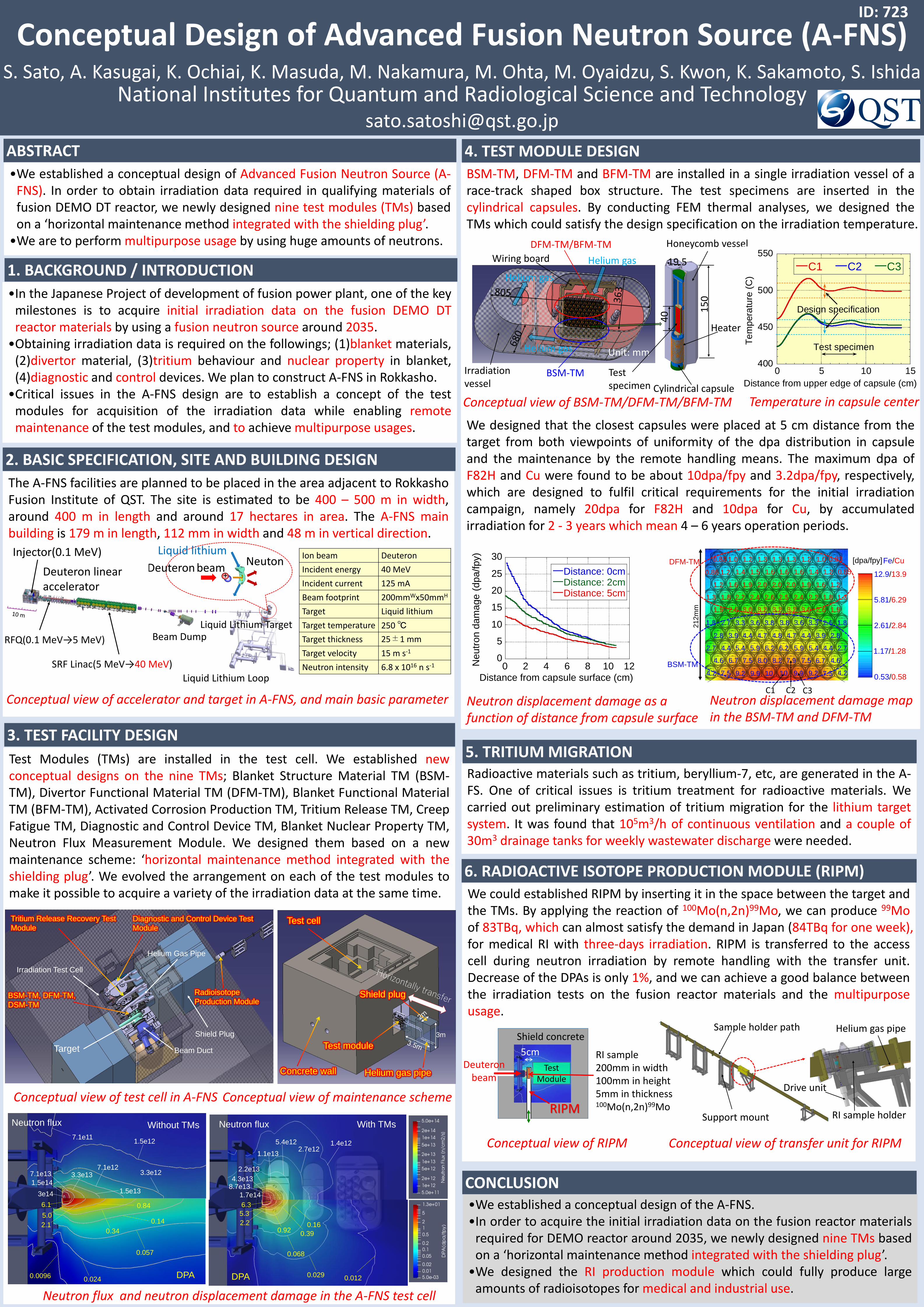
BSM-TM, DFM-TM and BFM-TM are installed in a single irradiation vessel of arace-track shaped box structure. The test specimens are inserted in thecylindrical capsules. By conducting FEM thermal analyses, we designed theTMs which could satisfy the design specification on the irradiation temperature.
We designed that the closest capsules were placed at 5 cm distance from thetarget from both viewpoints of uniformity of the dpa distribution in capsuleand the maintenance by the remote handling means. The maximum dpa ofF82H and Cu were found to be about 10dpa/fpy and 3.2dpa/fpy, respectively,which are designed to fulfil critical requirements for the initial irradiationcampaign, namely 20dpa for F82H and 10dpa for Cu, by accumulatedirradiation for 2 - 3 years which mean 4 – 6 years operation periods.
4. TEST MODULE DESIGN
2. BASIC SPECIFICATION, SITE AND BUILDING DESIGN
The A-FNS facilities are planned to be placed in the area adjacent to RokkashoFusion Institute of QST. The site is estimated to be 400 – 500 m in width,around 400 m in length and around 17 hectares in area. The A-FNS mainbuilding is 179 m in length, 112 mm in width and 48 m in vertical direction.
RFQ(0.1 MeV→5 MeV)
SRF Linac(5 MeV→40 MeV)
Injector(0.1 MeV)
Deuteron beam+
Liquid lithium
BSM-TM
DFM-TM/BFM-TM
Irradiationvessel
Helium gas
Helium gas
Helium gas
Wiring board
Testspecimen
Honeycomb vessel
Cylindrical capsule
40 1
50
19.5
Unit: mm
Heater
0
5
10
15
20
25
30
0 2 4 6 8 10 12
Distance: 0cmDistance: 2cmDistance: 5cm
Ne
utr
on
da
ma
ge
(d
pa/fpy)
Distance from capsule surface (cm)
12.9/13.9
5.81/6.29
2.61/2.84
1.17/1.28
0.53/0.58
[dpa/fpy]Fe/Cu
4.24.2 7.5 9.2 9.9 10 10 9.29.9 7.5
4.6 6.7 7.5 8.0 8.2 7.9 6.77.5 4.6
2.72.7 4.4 5.4 5.9 6.2 6.2 5.45.9 4.4
2.8 3.9 4.4 4.7 4.8 4.7 3.94.4 2.8
1.81.8 2.7 3.3 3.6 3.8 3.8 3.33.6 2.6
1.9 2.6 3.0 3.2 3.2 3.2 2.63.0 1.9
1.31.3 1.8 2.2 2.4 2.6 2.5 2.22.4 1.8
1.2 1.6 1.9 2.0 2.0 2.0 1.61.9 1.2
0.850.86 1.2 1.4 1.5 1.6 1.6 1.41.6 1.2
0.83 1.0 1.2 1.3 1.3 1.3 1.01.2 0.83
212
mm
BSM-TM
DFM-TM
We could established RIPM by inserting it in the space between the target andthe TMs. By applying the reaction of 100Mo(n,2n)99Mo, we can produce 99Moof 83TBq, which can almost satisfy the demand in Japan (84TBq for one week),for medical RI with three-days irradiation. RIPM is transferred to the accesscell during neutron irradiation by remote handling with the transfer unit.Decrease of the DPAs is only 1%, and we can achieve a good balance betweenthe irradiation tests on the fusion reactor materials and the multipurposeusage.
6. RADIOACTIVE ISOTOPE PRODUCTION MODULE (RIPM)
400
450
500
550
0 5 10 15
C1 C2 C3
Te
mp
era
ture
(C
)
Distance from upper edge of capsule (cm)
Test specimen
Design specification
Ion beam Deuteron
Incident energy 40 MeV
Incident current 125 mA
Beam footprint 200mmWx50mmH
Target Liquid lithium
Target temperature 250 ℃
Target thickness 25±1 mm
Target velocity 15 m s-1
Neutron intensity 6.8 x 10¹⁶ n s-1
Conceptual view of BSM-TM/DFM-TM/BFM-TM Temperature in capsule center
Sample holder path
Support mount
Drive unit
Helium gas pipe
RI sample holder
Deuteronbeam
TestModule
RIPM
Test Modules (TMs) are installed in the test cell. We established newconceptual designs on the nine TMs; Blanket Structure Material TM (BSM-TM), Divertor Functional Material TM (DFM-TM), Blanket Functional MaterialTM (BFM-TM), Activated Corrosion Production TM, Tritium Release TM, CreepFatigue TM, Diagnostic and Control Device TM, Blanket Nuclear Property TM,Neutron Flux Measurement Module. We designed them based on a newmaintenance scheme: ‘horizontal maintenance method integrated with theshielding plug’. We evolved the arrangement on each of the test modules tomake it possible to acquire a variety of the irradiation data at the same time.
3. TEST FACILITY DESIGN
Conceptual view of test cell in A-FNS
Target
Shield Plug
BSM-TM, DFM-TM,
DSM-TM
Tritium Release Recovery Test
Module
Diagnostic and Control Device Test
Module
Irradiation Test Cell
Helium Gas Pipe
Beam Duct
Radioisotope
Production Module
Test cell
Concrete wall
Shield plug
Test module
3m
Helium gas pipe
3e14
1.5e14
7.1e13 3.3e13
1.5e13
7.1e123.3e12
1.5e127.1e11
6.1
5.0
2.1
0.84
0.34
0.14
0.057
0.0240.0096
1.7e14
8.7e134.3e13
2.2e13
1.1e13
5.4e122.7e12
1.4e12
6.3
5.3
2.20.92
0.39
0.16
0.068
0.029 0.012
Without TMs With TMsNeutron flux Neutron flux
DPA DPA
RI sample200mm in width 100mm in height 5mm in thickness100Mo(n,2n)99Mo
Conceptual view of transfer unit for RIPMConceptual view of RIPM
Deuteron linear accelerator
Beam Dump
Liquid Lithium Loop
Liquid Lithium Target
Neuton
Conceptual view of accelerator and target in A-FNS, and main basic parameter
Conceptual view of maintenance scheme
Neutron flux and neutron displacement damage in the A-FNS test cell
Neutron displacement damage as a function of distance from capsule surface
Neutron displacement damage map in the BSM-TM and DFM-TM
5cm
Shield concrete
C1 C2 C3